EP1519091A2 - Tubing pinch valve - Google Patents
Tubing pinch valve Download PDFInfo
- Publication number
- EP1519091A2 EP1519091A2 EP04023214A EP04023214A EP1519091A2 EP 1519091 A2 EP1519091 A2 EP 1519091A2 EP 04023214 A EP04023214 A EP 04023214A EP 04023214 A EP04023214 A EP 04023214A EP 1519091 A2 EP1519091 A2 EP 1519091A2
- Authority
- EP
- European Patent Office
- Prior art keywords
- fluid
- chamber
- cartridge
- pinch valve
- valve
- Prior art date
- Legal status (The legal status is an assumption and is not a legal conclusion. Google has not performed a legal analysis and makes no representation as to the accuracy of the status listed.)
- Granted
Links
- 239000012530 fluid Substances 0.000 claims abstract description 182
- 238000007789 sealing Methods 0.000 claims abstract description 85
- 238000004891 communication Methods 0.000 claims abstract description 33
- 238000009428 plumbing Methods 0.000 claims abstract description 31
- 230000004913 activation Effects 0.000 claims description 16
- 230000007246 mechanism Effects 0.000 claims description 16
- 238000000034 method Methods 0.000 claims description 7
- 230000001105 regulatory effect Effects 0.000 claims description 7
- 239000013536 elastomeric material Substances 0.000 claims description 4
- 238000009420 retrofitting Methods 0.000 claims description 2
- XLYOFNOQVPJJNP-UHFFFAOYSA-N water Substances O XLYOFNOQVPJJNP-UHFFFAOYSA-N 0.000 description 47
- 230000008878 coupling Effects 0.000 description 7
- 238000010168 coupling process Methods 0.000 description 7
- 238000005859 coupling reaction Methods 0.000 description 7
- 239000000463 material Substances 0.000 description 5
- 238000011010 flushing procedure Methods 0.000 description 3
- 238000012856 packing Methods 0.000 description 3
- 230000004075 alteration Effects 0.000 description 2
- 230000003247 decreasing effect Effects 0.000 description 2
- 230000007812 deficiency Effects 0.000 description 2
- 238000012423 maintenance Methods 0.000 description 2
- 238000012986 modification Methods 0.000 description 2
- 230000004048 modification Effects 0.000 description 2
- 238000012546 transfer Methods 0.000 description 2
- 244000145845 chattering Species 0.000 description 1
- 238000010276 construction Methods 0.000 description 1
- 238000013461 design Methods 0.000 description 1
- 230000007257 malfunction Effects 0.000 description 1
- 230000013011 mating Effects 0.000 description 1
- 238000004137 mechanical activation Methods 0.000 description 1
- 239000007769 metal material Substances 0.000 description 1
- -1 polyethylene terephthalate Polymers 0.000 description 1
- 229920000139 polyethylene terephthalate Polymers 0.000 description 1
- 239000005020 polyethylene terephthalate Substances 0.000 description 1
- 230000008569 process Effects 0.000 description 1
- 230000009467 reduction Effects 0.000 description 1
- 230000000284 resting effect Effects 0.000 description 1
- 239000012056 semi-solid material Substances 0.000 description 1
- 239000011343 solid material Substances 0.000 description 1
- 229910001220 stainless steel Inorganic materials 0.000 description 1
- 239000010935 stainless steel Substances 0.000 description 1
- 230000003068 static effect Effects 0.000 description 1
- 229920002994 synthetic fiber Polymers 0.000 description 1
Images


Classifications
-
- E—FIXED CONSTRUCTIONS
- E03—WATER SUPPLY; SEWERAGE
- E03D—WATER-CLOSETS OR URINALS WITH FLUSHING DEVICES; FLUSHING VALVES THEREFOR
- E03D3/00—Flushing devices operated by pressure of the water supply system flushing valves not connected to the water-supply main, also if air is blown in the water seal for a quick flushing
- E03D3/02—Self-closing flushing valves
- E03D3/06—Self-closing flushing valves with diaphragm valve and pressure chamber for retarding the valve-closing movement
-
- F—MECHANICAL ENGINEERING; LIGHTING; HEATING; WEAPONS; BLASTING
- F16—ENGINEERING ELEMENTS AND UNITS; GENERAL MEASURES FOR PRODUCING AND MAINTAINING EFFECTIVE FUNCTIONING OF MACHINES OR INSTALLATIONS; THERMAL INSULATION IN GENERAL
- F16K—VALVES; TAPS; COCKS; ACTUATING-FLOATS; DEVICES FOR VENTING OR AERATING
- F16K31/00—Actuating devices; Operating means; Releasing devices
- F16K31/12—Actuating devices; Operating means; Releasing devices actuated by fluid
- F16K31/36—Actuating devices; Operating means; Releasing devices actuated by fluid in which fluid from the circuit is constantly supplied to the fluid motor
- F16K31/38—Actuating devices; Operating means; Releasing devices actuated by fluid in which fluid from the circuit is constantly supplied to the fluid motor in which the fluid works directly on both sides of the fluid motor, one side being connected by means of a restricted passage and the motor being actuated by operating a discharge from that side
- F16K31/385—Actuating devices; Operating means; Releasing devices actuated by fluid in which fluid from the circuit is constantly supplied to the fluid motor in which the fluid works directly on both sides of the fluid motor, one side being connected by means of a restricted passage and the motor being actuated by operating a discharge from that side the fluid acting on a diaphragm
-
- F—MECHANICAL ENGINEERING; LIGHTING; HEATING; WEAPONS; BLASTING
- F16—ENGINEERING ELEMENTS AND UNITS; GENERAL MEASURES FOR PRODUCING AND MAINTAINING EFFECTIVE FUNCTIONING OF MACHINES OR INSTALLATIONS; THERMAL INSULATION IN GENERAL
- F16K—VALVES; TAPS; COCKS; ACTUATING-FLOATS; DEVICES FOR VENTING OR AERATING
- F16K7/00—Diaphragm valves or cut-off apparatus, e.g. with a member deformed, but not moved bodily, to close the passage ; Pinch valves
- F16K7/02—Diaphragm valves or cut-off apparatus, e.g. with a member deformed, but not moved bodily, to close the passage ; Pinch valves with tubular diaphragm
- F16K7/04—Diaphragm valves or cut-off apparatus, e.g. with a member deformed, but not moved bodily, to close the passage ; Pinch valves with tubular diaphragm constrictable by external radial force
- F16K7/07—Diaphragm valves or cut-off apparatus, e.g. with a member deformed, but not moved bodily, to close the passage ; Pinch valves with tubular diaphragm constrictable by external radial force by means of fluid pressure
Definitions
- the present invention relates generally to flush valves used in connection with plumbing fixtures, such as toilets, urinals and the like, and in particular, to a replacement for a diaphragm valve in such a plumbing fixture.
- Valves are used throughout many fluid transfer systems and in various applications, such as in the transfer and control of water conduit systems, and in particular in connection with plumbing fixtures in both residential and commercial settings.
- flush valves are typically used for control and operation of toilets, urinals and the like, such that when a user actuates a handle, water flows through the flush valve into a basin portion and out the drain.
- a common type of flush valve is a diaphragm flush valve.
- a diaphragm flush valve is disclosed in U.S. Patent No. 4,327,891 to Allen et al.
- the Allen patent discloses the use of a diaphragm in a flush valve, where the diaphragm is made of molded rubber and serves to effectuate the flow of water from a water inlet, through the valve and to a water outlet.
- the Allen patent sets forth the various components and sub-components of the flush valve according to the prior art.
- Such diaphragm flush valves have several drawbacks.
- the relatively small seal area in the diaphragm can become clogged with debris, which causes the flush valve to remain open, resulting in constant water flow.
- a small bleed hole is used in order to allow enough volume to flow through the valve in order to flush the toilet or urinal. This small bleed hole is easily clogged, which can also result in the malfunction of the valve.
- the flushing cycle of the diaphragm flush valve takes approximately seven seconds to complete, depending upon the flow rates and water pressure entering the valve, due to the design of the diaphragm of the flush valve. Since an upper chamber fills slowly, the valve is slowly "shutting off".
- Pinch valves have found use in various valve applications other than a diaphragm-type valve.
- U.S. Patent No. 4,111,391 to Pilolla discloses a pinch valve including a distortable rubber-like valve member in a generally cylindrical form.
- the valve member has uniformly spaced projections and grooves enabling it to collapse upon itself and form a complete closure between opposite ends.
- the use of such a pinch valve as a replacement valve in the application of flush valves for plumbing fixtures has not been effective due to the different sealing arrangement bound in pinch valves in comparison to diaphragm valves. Therefore, there remains a need for an effective valve for replacing a diaphragm flush valve in a plumbing fixture.
- the present invention is directed to a pinch valve for use in a plumbing fixture, and is particularly adapted for replacement of a diaphragm valve in a plumbing fixture.
- the plumbing fixture includes an inlet chamber defining a fluid inlet, which is in fluid communication with an internal chamber defining a fluid outlet.
- the pinch valve includes a cartridge member having a fluid inlet opening, a fluid outlet opening and a cartridge chamber defined by a cartridge chamber wall.
- the cartridge chamber is in fluid communication with the fluid inlet opening and the fluid outlet opening.
- a flexible sealing member is positioned at least partially within the cartridge chamber and has a wall with an inner surface defining a flow chamber and an outer surface defining a pressure chamber between the outer surface of the flexible sealing member wall and the cartridge chamber wall.
- the inlet chamber of the plumbing fixture is in fluid communication with the flow chamber and the pressure chamber.
- fluid force in the pressure chamber is at least equal to fluid force in the flow chamber.
- the wall of the flexible member constricts inwardly and pinches, thereby preventing fluid flow through the flow chamber.
- the fluid force in the pressure chamber is less than the fluid force in the flow chamber.
- the wall collapses to an unpinched position, thereby permitting fluid flow through the flow chamber and causing water to flow through the flush valve for flushing of the fixture.
- the present invention is also directed to a plumbing fixture.
- the plumbing fixture includes an inlet chamber defining a fluid inlet in fluid communication with an internal chamber defining a fluid outlet.
- the plumbing fixture also includes a pinch valve having a cartridge member with a fluid inlet opening, a fluid outlet opening and a cartridge chamber defined by a cartridge chamber wall and in fluid communication with the fluid inlet opening and the fluid outlet opening.
- the pinch valve further includes a flexible sealing member positioned at least partially within the cartridge chamber and having a wall with an inner surface defining a flow chamber and an outer surface defining a pressure chamber between the outer surface of the flexible sealing member wall and a cartridge chamber wall.
- the inlet chamber of the plumbing fixture is in fluid communication with the flow chamber and the pressure chamber as described above.
- FIG. 1 is a cross-sectional clevational view of a diaphragm flush valve according to the prior art
- FIG. 2 is a cross-sectional elevational view of a flush valve incorporating a pinch valve element in accordance with the present invention
- FIG. 3 is an exploded perspective view of the flush valve including the pinch valve element of FIG. 2;
- FIG. 4 is an exploded perspective view of the pinch valve replacement element of FIG. 2;
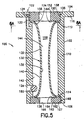
- FIG. 5 is a cross-sectional view of the pinch valve replacement element of FIG. 2;
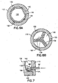
- FIG. 6A is a cross-sectional view taken along lines 6-6 of FIG. 5 shown in an collapsed unsealed position, while FIG. 6B is a similar cross-sectional view shown in a pinched or constricted sealing position;
- FIG. 7 is a detailed sectional view of a seal portion of the pinch valve element of FIG.5;
- FIG. 8 is a side cross-sectional view of a pinch valve replacement element shown in an alternative embodiment
- FIG. 9 is a cross-sectional view of a flush valve incorporating a pinch valve element in a further embodiment of the present invention showing an alternative activation mechanism.
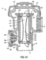
- FIG. 10 is a cross-sectional view of a flush valve incorporating a pinch valve clement in yet a further embodiment of the present invention showing a pressurizing unit for valve control.
- the present invention relates to flush valves, and in particular to an improved valve insert for use in such valves.
- the valve insert is particularly useful for replacement of a traditional diaphragm-type valve insert for flush valves.
- Such traditional diaphragm-type valves are shown in U.S. Patent No. 4,327,891, as depicted in FIG. 1 herein.
- the flush valve 2 has a general hollow body 10 which includes an inlet connection 12, an outlet connection 15 and a handle coupling connection 16.
- the top of the valve body is closed by an outer cover 18 and an inner cover 20.
- the inlet portion of the valve is separated from the outlet portion by a central throat 22 which is attached to the inside walls of the valve body 10.
- a main valve seat 24 is formed on the top of the throat.
- the valve is actuated by an operating handle 26 which is fastened to the valve body 10 by means of coupling nut 28.
- the handle is connected to a plunger 30 which extends to the interior portion of the valve body.
- the plunger 30 is guided and supported by a bushing 32 and restored by a spring 34.
- a rubber sealing cap or packing 36 is snapped on the end of bushing 32 and prevents leakage outward from the handle opening.
- the annular valve seat 24 is normally closed by a diaphragm 38.
- the diaphragm extends across the body 10 and defines an upper chamber 40.
- the diaphragm has a by-pass 42 which provides fluid communication between the inlet side of the valve and the upper chamber 40.
- a filter 44 may be provided to prevent clogging of the by-pass 42.
- the diaphragm 38 is attached at its outer edge to the valve body.
- the outer cover 18 clamps the diaphragm between a shoulder on the valve body and the inner cover 20.
- the center of the diaphragm has an opening which allows fluid communication between the upper chamber 40 and the outlet 14.
- a relief valve shown generally at 46 is attached to the diaphragm and normally closes the opening at the center of the diaphragm.
- the relief valve 46 includes a guide portion 48 having wings 49. The wings 49 fit closely against the inside diameter of the throat 22.
- the guide 48 also has a lip 50.
- the lip supports a collar 52.
- the relief valve 46 includes a clamping member 54 which is threadedly engaged with the guide portion 48.
- the clamping member 54 clamps the inner edge of the diaphragm 38 between the member 54 and the collar 52.
- the clamping member 54 has a hole in the middle which is normally closed by an auxiliary valve member 56, This member is connected to a depending stem 58 which extend to a point opposite the actuating plunger 30.
- the clamping member 54 may have a rubber liner to improve the sealing contact between the auxiliary valve member 56 and the clamping member.
- this prior art valve is as follows. In the normally-closed position shown in FIG. 1, water pressure at the valve inlet is communicated to the upper chamber 40 through the by-pass 42. Since the surface area subjected to the water pressure is greater on the upper side of the diaphragm, the water pressure forces the diaphragm down onto the valve seat 24. This prevents water from flowing to the outlet 14, When a user rotates the handle 26 in any direction the plunger 30 moves inwardly, tilting the stem 58 and moving the auxiliary valve member 56 out of the sealing engagement with the clamping member 54. This relieves the pressure in the upper chamber 40 by allowing water to flow through the guide member 48.
- flush valves incorporating such a diaphragm 38 have numerous drawbacks and other deficiencies.
- the present invention is directed to a valve element as a replacement for the diaphragm in a conventional valve body. More particularly, with specific reference to FIGS. 2-8, the valve element of the present invention includes a pinch valve replacement element 100 which is provided for use with a conventional flush valve body such as previously described in terms of the prior art including flush valve 2', a hollow body 10', an inlet connection 12', an outlet connection 14', and a handle coupling connection 16'.
- pinch valve replacement element 100 replaces the diaphragm valve mechanism used in prior art valve bodies, and as such sits directly within hollow body 10' on main valve seat 24' in direct communication with central throat 22', providing a mechanism for regulating water flow through the valve body by way of central throat 22', as will be discussed in more detail herein.
- Pinch valve replacement element 100 generally includes a cylindrical cartridge member 102 and a dynamic pinch-type flexible sealing member 130 provided within the cartridge member 102.
- Cartridge member 102 is defined by a tubular cartridge chamber wall 110 extending between a first open end 102 forming a fluid inlet opening and a second open end 104 forming a fluid outlet opening, and further defining an internal chamber 108 extending therethrough.
- the internal chamber 108 provides direct fluid communication between the fluid inlet opening defined by first open end 104 and the fluid outlet opening defined by second open end 106.
- a fluid channel 120 extends through the cartridge chamber wall 110, desirably at a position adjacent first open end 104.
- Such fluid channel 120 includes a fluid inlet opening 122, which may be present on the top surface of cartridge member 102 adjacent first open end 104 thereof. Desirably, a plurality of fluid channels 120 are provided through the cartridge chamber wall 110 and may be spaced from each other, such as depicted in FIGS. 6A-6B.
- the fluid inlet opening preferably has a diameter which is less than the diameter of the fluid inlet established through fluid channel 156 of upper clamping member 150.
- this fluid channel 120 provides a mechanism for fluid flow from the upper chamber 40' of the valve body into the pinch valve replacement element 100, which fluid flow regulates sealing of the valve for operation of the valve, as will be described in more detail herein.
- Fluid channel 120 may further be provided with a filter device (not shown) which prevents solid or semi-solid material from flowing through or clogging the fluid channel 120.
- the pinch valve replacement element 100 further includes a flexible sealing member 130 positioned within the internal chamber 108 of the cartridge member 102.
- the flexible sealing member 130 includes a flexible tubular wall 132 extending between a first open end 132 positioned-adjacent first open end 104 of cartridge member 102, and a second open end 134 positioned adjacent second open end 106 of cartridge member 102. As such, the flexible sealing member 130 is positioned at least partially within the cartridge member 108, and extends substantially between first open end 104 and second open end 106 of cartridge member 102.
- first open end 134 of the flexible sealing member 130 is fixed upon an upper annular rim 112 defined within the first open end 104 of the cartridge member 102.
- second open end 136 of the flexible sealing member 130 is fixed upon a lower annular rim 114 defined within the second open end 106 of the cartridge member 102.
- Any means of affixing the ends of the flexible sealing member 130 to the ends of the cartridge member 102 may be employed. Desirably, this is accomplished through a mechanical securement, such as through upper clamping member 150 and lower clamping member 160, as best depicted in FIGS. 4 and 5.
- Upper clamping member 150 desirably includes a generally disc-shaped cylindrical body extending between an upper, external surface 152 and a lower, internal surface 154, with an internal fluid channel 156 extending therethrough.
- the outer cylindrical surface of upper clamping member 150 is threaded with external threads 158 for threaded engagement with internal threads 105 which extend within the inner surface of first open end 104 of cartridge member 102.
- lower clamping member 160 desirably includes a generally disc-shaped cylindrical body extending between a lower, external surface 162 and an upper, internal surface 164, with an internal fluid channel 166 extending therethrough.
- lower clamping member 150 The outer cylindrical surface of lower clamping member 150 is threaded with external threads 168 for threaded engagement with internal threads 107 which extend within the inner surface of second open end 106 of cartridge member 102.
- external threads 168 of lower clamping member 160 By threading such external threads 168 of lower clamping member 160 with the internal threads 107 of cartridge member 102, the second open end 134 of the flexible sealing member 130 can be effectively trapped between the internal surface 164 of lower clamping member 160 and the lower annular rim 114 of cartridge member 102, thereby effectively securing the entire annular rim of the second open end 136 of flexible sealing member 130 therebetween.
- both of the ends 134, 136 of the flexible sealing member 130 are statically sealed with respect to cartridge member 102.
- Cartridge member 102 and upper and lower clamping members 150, 160 may be constructed of any rigid material, for example a metallic material such as stainless steel, or a rigid polymeric material, such as polyethylene terephthalate.
- fluid channel 156 of upper clamping member 150 defines an inlet opening for fluid flow into cartridge chamber 108
- fluid channel 166 of lower clamping member 160 defines an outlet opening for fluid flow out of cartridge chamber 108, as will be discussed in more detail herein.
- a first chamber is provided as pressure chamber 142, defined between the inner wall surface of cartridge chamber wall 110 and the outer wall surface 140 of tubular wall 132 of flexible sealing member 130.
- a path for fluid flow between this pressure chamber 142 and the external area of the pinch valve replacement element 100 is provided through the fluid channel 120 which extends through the cartridge chamber wall 110 of cartridge chamber 102 adjacent the first open end 104 thereof.
- a second chamber is provided as flow chamber 144, defined as the interior chamber within inner wall surface 138 of tubular wall 132 of flexible sealing member 130.
- the fluid channels 156, 166 of upper clamping members 150, 160 are in fluid communication with this flow chamber 144.
- fluid flow through the pinch valve replacement element 100, and therefore fluid flow through the valve body itself is regulated by the fluid pressure within pressure chamber 142 which regulates the pinching or collapsing of the flexible sealing member 130 to close or open this flow chamber 144, thereby regulating fluid flow between fluid channel 156 and fluid channel 166.
- the flexible sealing member 130 is constructed of an elastomeric material, such as rubber, a polymeric material or other synthetic material having elastomeric properties. Further, in order to reduce the chances of failure and reduce the costs of maintenance, a portion or all of the walls of the flexible sealing member 130 may be reinforced with a semirigid material. Flexible sealing member 130 is moveable between a collapsed state as shown in FIG. 6A, in which the tubular wall 132 is collapsed, defining flow chamber 144 therein, and a constricted or pinched state as shown in FIG. 6B, in which the tubular wall 132 is pinched or gathered to form a closed structure in which flow chamber 144 is entirely closed off.
- flexible sealing member 130 is capable of folding to form a plurality of folded walls which mate with each other and meet together at the center of the pinched sleeve to form a generally complete closure. This folding may be assisted by providing a plurality of grooves 148 on the outer wall surface 140 to act as a weakened portion of tubular wall 132 of flexible sealing member 130. Desirably, three grooves 148 are provided such that flexible sealing member 130 pinches off to form three pairs of mating wall structures which meet at a center point, closing off flow chamber 144.
- the inner wall surface 138 of tubular wall 132 may include protrusions at a point corresponding to each of grooves 148 such that, upon pinching off, the protrusions meet at a center point to ensure complete closing of flow chamber 144.
- Pinch valve replacement element 100 is positioned within the hollow body 10' of the flush valve 2', and in particular, within central throat 22'.
- the cylindrical shape of the cartridge member 102 is dimensioned such that cartridge chamber wall 110 has an outer diameter which is substantially the same size, or only slightly smaller than, the internal diameter of central throat 22', such that a snug fit is achieved with little or no annular space therebetween.
- the cartridge member 102 may also include a rim portion 116 with a rim portion undersurface 118.
- the rim portion undersurface 118 is sized and shaped so as to engage with and form a seal with the upper edge defining the main valve seat 24' of the central throat 22' of the plumbing fixture.
- the undersurface 118 of the rim portion 116 may include a layer capable of forming a seal, desirably an elastomeric layer or other layer such as a coated layer, a bonded layer, or other similar seal area.
- Cartridge member 102 further includes a plunger channel 124 extending through the cartridge chamber wall 110 at a location between the upper annular rim 112 within first open end 104 and the lower annular rim 114 within second open end 106. In this manner, plunger channel 124 establishes a path for fluid flow between pressure chamber 142 and the external environment, namely outlet connection 14', through the cartridge wall 110.
- plunger channel 124 is aligned with plunger 30', which is interconnected with operating handle 26' and extends through hollow body 10' through coupling nut 28', bushing 32', spring 34' and packing 36' as described above in connection with FIG. 1 with reference to the prior art.
- plunger 30' may be positioned so as to extend slightly within plunger channel 124, which extends through cartridge chamber wall 110.
- plunger channel 124 is desirably larger in diameter than plunger 30' to provide sliding movement of plunger 30' therein and to permit fluid to flow around plunger 30' through plunger channel 124.
- plunger channel 124 includes a sealing member, and preferably a spherical sealing member such as ball seal 180, for closing fluid channel 120 to prevent fluid flow therethrough.
- a sealing member is a ball seal 180 positioned within pressure chamber 142 and adapted to seal against the inner surface of the cartridge chamber wall 110 at the interior opening forming plunger channel 124, as shown in FIG. 5.
- This sealing member may be constructed of any material capable of sealing fluid channel 120 for fluid flow, and is desirably an elastomeric material such as rubber. It is also contemplated that plunger 30' may be provided with an enlarged end surface to act as such a sealing member.
- pinch valve replacement element 100 is provided as an integral unit for replacement of a diaphragm-type valve element for retrofitting an existing flush valve
- a separate extension piece can be provided for attachment to the end of plunger 30' so as to extend within plunger channel 124 and seal off the opening and prevent fluid flow therethrough.
- Flush valve 2' is provided with hollow body 10', and may be appropriately connected to a water source through inlet connection 12', and to a plumbing fixture such as a toilet, a urinal, or the like, through outlet connection 14'. Also, operating handle 26', as well as the corresponding plunger 30', bushing 32', spring 34' and packing 36' components, may be connected to handle coupling connection 16' through coupling not 28'.
- Pinch valve replacement element 100 is provided within central throat 22', with rim portion 116 resting on main valve seat 24' in a sealing engagement.
- Pinch valve replacement element 100 is positioned such that plunger channel 124 is aligned with plunger 30', and desirably, such that plunger 30' slightly extends within plunger channel 124.
- Inner cover 20' if provided, may then be placed over flush valve 2', with outer cover 18' thereafter threaded onto hollow body 10' to enclose flush valve 2'.
- pinch valve replacement element 100 provides a valve element for regulating fluid flow, in particular water flow, between inlet connection 12' and outlet connection 14'.
- the present invention is directed to a flush valve including the pinch valve element therein, as well as to the pinch valve element for use as a replacement or retrofit for a diaphragm-type valve. Accordingly, in use as a replacement or retrofit application, assembly of the flush valve 2' may first involve removing the outer and inner covers, and removing a diaphiagm-type valve, such as the diaphragm 38 and all corresponding parts described in connection with the prior art with reference to FIG. 1.
- the pinch valve replacement element 100 can be placed within the central throst 22' of hollow body 10' as described above, with plunger 30' aligned with plunger channel 124, and with the inner and outer covers 20', 18' replaced onto hollow body 10'.
- flush valve 2' including pinch valve replacement element 100 therein is connected to an appropriate source of water through inlet connection 12' and to an appropriate fixture through outlet connection 14'.
- Pinch valve replacement element 100 is sealed off because flexible sealing member 130 is pinched. This is achieved by the fluid force in the pressure chamber 142 being at least equal to the fluid force in the flow chamber 144.
- water flows into upper chamber 40' of flush valve 2' from inlet connection 12', and passes into fluid inlet opening 122 and through fluid channel 120 into pressure chamber 142.
- the flexible tubular wall 132 of flexible sealing member 130 pinches and/or folds along grooves 148, closing off flow chamber 144 and forming a closed structure as seen in FIG. 6B.
- flexible ceiling number 130 is depicted in FIGS. 2 and 5 in an open position for illustrative purposes only, and would normally be pinched and sealed when ball seal 180 seals pressure chamber 142.
- the tubular wall 132 of the flexible sealing member 130 folds inwardly and pinches the inner wall surface 138 of the flexible sealing member 138 against itself. Accordingly, this prevents fluid flow through the flow chamber 144.
- Plunger channel 124 cannot remain permanently open or sufficient pressure cannot build in the pressure chamber 142. Accordingly, during this water flow through flush valve 2', sufficient water passes through the flush valve 2' through cartridge chamber 108 to flush the fixture, while water is simultaneously passing through fluid inlet opening 122 and through fluid channel 120 into pressure chamber 142. This flow of water into pressure chamber 142 gradually increases the fluid pressure within pressure chamber 142, and causes, the sealing member, which is provided for example through ball seal 180, to re-engage and re-seal the opening to plunger channel 124 to prevent any further fluid flow therethrough. When the plunger channel 124 is sealed by the ball seal 180 as such, fluid can collect in the pressure chamber 142 at a more rapid pace.
- a sloped surface 186 may be provided immediately adjacent and be sloped toward the inner wall opening at plunger channel 124. In this manner, when the plunger 30' pushes and disengages the ball seal 180, and after the fluid is finished exiting through the plunger channel 124, the ball seal 180 slides or rolls back down the sloped surface 186 and to re-engage with the opening at plunger channel 124.
- pinch valve replacement element 100 can be provided as an integral unit with flexible sealing member 130 secured within cartridge member 102 as described. In this manner, the pinch valve replacement member 100 can be easily inserted into the central throat 22' of hollow body 10 of a flush valve body, and serves as an easy replacement for a removed diaphragm valve element. Accordingly, the present invention is directed not only to a pinch valve as described hereinabove, but also to a plumbing fixture, such as a flush valve assembly, which includes such a pinch valve in combination with a flush valve assembly.
- FIG. 8 depicts a pinch valve replacement element 200 in a further embodiment of the present invention.
- the cartridge member is substantially identical to the previously described embodiment, with the exception that the fluid channel does not extend through the cartridge chamber wall.
- a different type of upper clamping member 250 is provided for securing the flexible sealing member within the cartridge member, which upper clamping member 250 includes a fluid channel 220 including a fluid inlet opening 222.
- the flexible sealing member includes a bleed hole 226 extending through the wall thereof at a position adjacent and aligned with the fluid channel 220.
- the pinch valve replacement element 200 works in a similar manner as in the previous embodiment, except that in order for the flexible sealing member to constrict and pinch the valve closed, water enters into the pressure chamber through the upper clamping member 250 as opposed to through the cartridge chamber wall of the cartridge chamber, that is, through the fluid inlet opening 222, through the fluid channel 220, and through the bleed hole 226, as shown in FIG. 8. It is noted that a plurality of fluid channels 220 may be provided through the upper clamping member, and may be properly spaced thereabout.
- FIG. 9 depicts a further embodiment of the present invention, in which the mechanical activation mechanism for the flush valve is substituted or replaced with an electronic activation mechanism, such as a solenoid mechanism.
- the flush valve 2' including the pinch valve replacement element 100 is identical to the embodiment described in connection with FIGS. 1-7, but substituting the previously described operating handle with a solenoid assembly 190.
- Solenoid assembly 190 may be any assembly capable of providing a linear movement upon activation, as is known in the art.
- solenoid assembly 190 Upon activation, solenoid assembly 190 causes a linear movement of plunger 30', which in turn causes activation of the pinch valve assembly for water flow through the flush valve for flushing of the fixture, as previously described.
- Activation of the solenoid assembly may be accomplished in any known manner, such as through contact with a push button 192 which activates the solenoid assembly 190.
- an electronic sensor assembly (not shown) may be associated with solenoid assembly 190 to cause automatic activation thereof, as is known in the art.
- FIG. 10 depicts a further variation on the embodiment of FIG. 9, with the solenoid element acting as a flow regulator as opposed to merely providing a linear actuator for activation of a plunger element.
- the flush valve 2' including the pinch valve replacement element 100 is identical to the embodiment described in connection with FIGS. 1-7, but substituting the previously described operating handle with a solenoid assembly 390 and eliminating the need for a ball seal. Instead, sealing of the pressure chamber 142 is achieved through water flow through the solenoid assembly 390.
- the solenoid assembly 390 may be interconnected to the pinch valve replacement element 100 through a flow channel 394 extending through the cartridge wall 110, thereby establishing fluid communication between pleasure chamber 142 and the solenoid assembly 390.
- Solenoid assembly 390 includes a housing which defines an interior flow chamber 391 therein, with a flow port 392 extending through the housing and providing a path for fluid communication between the interior flow chamber 391 and outlet 14', and with flow channel 394 in fluid communication with interior flow chamber 391.
- Solenoid assembly 390 further includes a solenoid coil 393 which surrounds a plunger 395 biased by spring 396 to the right, as illustrated in the drawings, or toward a position closing the flow port 392.
- the solenoid assembly 390 is attached to the valve body 10' through a coupling nut 28', and is interconnected with pinch valve replacement element 100 through a tubing such as flow channel 394. Solenoid assembly 390 may further be interconnected with an electronic sensor element for activation thereof.
- the plunger 395 is biased through spring 396 to a position closing and sealing flow port 392. In this position, a sealed environment is established such that pressure chamber 142 can fill with water as described previously, thereby constricting flexible wall 132 of flexible sealing member 130 and closing or pinching off the flow chamber 144.
- the solenoid assembly 390 is activated, such as through an infrared sensor (not shown), electric power is applied to the solenoid coil 393, causing the plunger 395 to move away from flow port 392. Water which is contained within pressure chamber 142 is then released and can then flow through flow channel 394 into interior flow chamber 391 and out through flow port 392 where it is released into outlet 14'. This releases the pressure within pressure chamber 142 which in turn causes the flexible wall 132 of flexible sealing member 130 to collapse, thereby opening flow chamber 144 and permitting water flow therethrough.
- the solenoid assembly 390 After the solenoid assembly 390 has been activated for a predetermined time period, such as five seconds, the electric power to the solenoid coil 393 is cut off, and the spring 396 with again bias plunger 395 against flow port 392, thereby closing it off and sealing off interior flow chamber 391. Pressure can then accumulate therein, and water will again flow through fluid inlet opening 122 and fluid channel 120 into pressure chamber 142, and will once again pinch off flow chamber 144 when sufficient pressure is established to constrict flexible wall 132.
- a predetermined time period such as five seconds
- FIG. 11 depicts yet a further embodiment of the present invention, in which the pinch valve replacement element 400 includes a pressure chamber 442 which is designed to be pressurized through an external air source as opposed to water flowing through the flush valve. More particularly, the activation mechanism of the previously described embodiment of FIG. 1-7 is replaced with an activation mechanism including a pressure source P.
- Cartridge wall 410 does not include any fluid channel extending therethrough, nor any plunger channel extending therethrough. Instead, an air channel 494 extends from pressure source P through the cartridge wall 410 and into pressure chamber 442. Pressurized air can therefore be provided from pressure source P through air channel 494 and into pressure chamber 442.
- flexible wall 132 of flexible sealing member 130 constricts to pinch off the flow chamber 144.
- an activation mechanism such as push button 492 causes the pressure source P to release the air pressure provided within pressure chamber 442, such as through an air bleed hole (not shown). This causes a decrease in the air pressure within pressure chamber 442, and once the pressure falls below a predetermined threshold, the water pressure acting upon the flexible wall of flexible sealing member 130 will overcome the air pressure and collapse flexible wall 132, thereby opening flow chamber 144 for water flow therethrough.
- pressure source P will once again provide air pressure through air channel 494 to re-pressurize pressure chamber 442, which in turn will cause the flexible wall 132 of flexible sealing member 130 to constrict and again pinch off flow chamber 144, stopping the flow of water therethrough.
- pressure source P as well as air channel 494 and pressure chamber 442, are appropriately sealed from both the external environment as well as to the internal water flow within the valve assembly, so as to be able to maintain proper pressure regulation therein and prevent water from entering the pressure source P.
- the present invention provides a more durable flush valve requiring less maintenance through the use of the pinch valve element as opposed to a standard conventional diaphragm-type valve. Due to the large seal area established by the wall 132 of the flexible sealing member 130 closing in on itself, even if debris is trapped or engaged in the pinched area, a seal is still realized. Also, the large diameter secondary fluid inlet opening established by fluid channel 156 is not easily clogged. In addition, the present invention provides a valve element that has a single static seal area as opposed to multiple sealing areas as in the diaphragm valve 12 according to the prior art.
- the pinch valve replacement element 100 of the present invention is capable of achieving flush flow-through times of about 3,5 seconds with a very high flow rate velocity when used in connection with a standard flush valve. Moreover, the pinch valve element is capable of being reset at very low fluid pressures, and therefore can reseal itself and close off water flow even when a facility loses mainline pressure.
Abstract
Description
- The present invention relates generally to flush valves used in connection with plumbing fixtures, such as toilets, urinals and the like, and in particular, to a replacement for a diaphragm valve in such a plumbing fixture.
- Valves are used throughout many fluid transfer systems and in various applications, such as in the transfer and control of water conduit systems, and in particular in connection with plumbing fixtures in both residential and commercial settings. For example, flush valves are typically used for control and operation of toilets, urinals and the like, such that when a user actuates a handle, water flows through the flush valve into a basin portion and out the drain.
- Presently, a common type of flush valve is a diaphragm flush valve. For example, such a diaphragm flush valve is disclosed in U.S. Patent No. 4,327,891 to Allen et al. The Allen patent discloses the use of a diaphragm in a flush valve, where the diaphragm is made of molded rubber and serves to effectuate the flow of water from a water inlet, through the valve and to a water outlet. Further, the Allen patent sets forth the various components and sub-components of the flush valve according to the prior art.
- Such diaphragm flush valves have several drawbacks. For example, the relatively small seal area in the diaphragm can become clogged with debris, which causes the flush valve to remain open, resulting in constant water flow. In addition, since the flush valve is pressurized, a small bleed hole is used in order to allow enough volume to flow through the valve in order to flush the toilet or urinal. This small bleed hole is easily clogged, which can also result in the malfunction of the valve. Still further, the flushing cycle of the diaphragm flush valve takes approximately seven seconds to complete, depending upon the flow rates and water pressure entering the valve, due to the design of the diaphragm of the flush valve. Since an upper chamber fills slowly, the valve is slowly "shutting off". Therefore, a significant amount of water is wasted through the trap and sewer line during the sealing process. The trip lever seal area can also be blocked with debris, which causes the valve to flow continuously. Yet another drawback is that conventional diaphragm flush values only work at water pressures greater than 35 psi, which is due to the difference in the diaphragm surface area and the diameter of the bleed hole.
- Pinch valves have found use in various valve applications other than a diaphragm-type valve. For example, U.S. Patent No. 4,111,391 to Pilolla discloses a pinch valve including a distortable rubber-like valve member in a generally cylindrical form. As disclosed in the Pilolla patent, the valve member has uniformly spaced projections and grooves enabling it to collapse upon itself and form a complete closure between opposite ends. Heretofore, however, the use of such a pinch valve as a replacement valve in the application of flush valves for plumbing fixtures has not been effective due to the different sealing arrangement bound in pinch valves in comparison to diaphragm valves. Therefore, there remains a need for an effective valve for replacing a diaphragm flush valve in a plumbing fixture.
- It is an object of the present invention to provide a valve replacement for a diaphragm valve that overcomes the deficiencies of the prior art. It is another object of the present invention to provide a valve replacement for a diaphragm valve that has a decreased failure rate and, therefore, an increased cost efficiency. It is a further object of the present invention to provide a valve replacement for a diaphragm valve that has a larger seal area, such that small debris cannot be trapped in the seal area and hold the valve open. It is a still further object of the present invention to provide a valve replacement for a diaphragm valve that has a decreased flush time with a high flow rate and velocity, thereby being more water efficient. It is yet another object of the present invention to provide a valve replacement for a diaphragm valve that is capable of resetting at low pressure, such as when a facility loses mainline pressure.
- The present invention is directed to a pinch valve for use in a plumbing fixture, and is particularly adapted for replacement of a diaphragm valve in a plumbing fixture. The plumbing fixture includes an inlet chamber defining a fluid inlet, which is in fluid communication with an internal chamber defining a fluid outlet. The pinch valve includes a cartridge member having a fluid inlet opening, a fluid outlet opening and a cartridge chamber defined by a cartridge chamber wall. The cartridge chamber is in fluid communication with the fluid inlet opening and the fluid outlet opening. A flexible sealing member is positioned at least partially within the cartridge chamber and has a wall with an inner surface defining a flow chamber and an outer surface defining a pressure chamber between the outer surface of the flexible sealing member wall and the cartridge chamber wall. The inlet chamber of the plumbing fixture is in fluid communication with the flow chamber and the pressure chamber.
- In an undisturbed state, fluid force in the pressure chamber is at least equal to fluid force in the flow chamber. In this situation, the wall of the flexible member constricts inwardly and pinches, thereby preventing fluid flow through the flow chamber. However, when the pressure chamber is relieved of pressure, the fluid force in the pressure chamber is less than the fluid force in the flow chamber. When this occurs, the wall collapses to an unpinched position, thereby permitting fluid flow through the flow chamber and causing water to flow through the flush valve for flushing of the fixture.
- The present invention is also directed to a plumbing fixture. The plumbing fixture includes an inlet chamber defining a fluid inlet in fluid communication with an internal chamber defining a fluid outlet. The plumbing fixture also includes a pinch valve having a cartridge member with a fluid inlet opening, a fluid outlet opening and a cartridge chamber defined by a cartridge chamber wall and in fluid communication with the fluid inlet opening and the fluid outlet opening. The pinch valve further includes a flexible sealing member positioned at least partially within the cartridge chamber and having a wall with an inner surface defining a flow chamber and an outer surface defining a pressure chamber between the outer surface of the flexible sealing member wall and a cartridge chamber wall. The inlet chamber of the plumbing fixture is in fluid communication with the flow chamber and the pressure chamber as described above.
- The present invention, both as to its construction and its method of operation, together with the additional objects and advantages thereof, will best be understood from the following description of exemplary embodiments when read in connection with the accompanying drawings.
- FIG. 1 is a cross-sectional clevational view of a diaphragm flush valve according to the prior art;
- FIG. 2 is a cross-sectional elevational view of a flush valve incorporating a pinch valve element in accordance with the present invention;
- FIG. 3 is an exploded perspective view of the flush valve including the pinch valve element of FIG. 2;
- FIG. 4 is an exploded perspective view of the pinch valve replacement element of FIG. 2;
- FIG. 5 is a cross-sectional view of the pinch valve replacement element of FIG. 2;
- FIG. 6A is a cross-sectional view taken along lines 6-6 of FIG. 5 shown in an collapsed unsealed position, while FIG. 6B is a similar cross-sectional view shown in a pinched or constricted sealing position;
- FIG. 7 is a detailed sectional view of a seal portion of the pinch valve element of FIG.5;
- FIG. 8 is a side cross-sectional view of a pinch valve replacement element shown in an alternative embodiment;
- FIG. 9 is a cross-sectional view of a flush valve incorporating a pinch valve element in a further embodiment of the present invention showing an alternative activation mechanism; and
- FIG. 10 is a cross-sectional view of a flush valve incorporating a pinch valve clement in yet a further embodiment of the present invention showing a pressurizing unit for valve control.
- The present invention relates to flush valves, and in particular to an improved valve insert for use in such valves. The valve insert is particularly useful for replacement of a traditional diaphragm-type valve insert for flush valves. Such traditional diaphragm-type valves are shown in U.S. Patent No. 4,327,891, as depicted in FIG. 1 herein. In such diaphragm-type flush valves, the
flush valve 2 has a generalhollow body 10 which includes aninlet connection 12, an outlet connection 15 and ahandle coupling connection 16. The top of the valve body is closed by anouter cover 18 and aninner cover 20. The inlet portion of the valve is separated from the outlet portion by acentral throat 22 which is attached to the inside walls of thevalve body 10. Amain valve seat 24 is formed on the top of the throat. - The valve is actuated by an
operating handle 26 which is fastened to thevalve body 10 by means ofcoupling nut 28. The handle is connected to aplunger 30 which extends to the interior portion of the valve body. Theplunger 30 is guided and supported by abushing 32 and restored by aspring 34. A rubber sealing cap or packing 36 is snapped on the end ofbushing 32 and prevents leakage outward from the handle opening. - The
annular valve seat 24 is normally closed by adiaphragm 38. The diaphragm extends across thebody 10 and defines anupper chamber 40. The diaphragm has a by-pass 42 which provides fluid communication between the inlet side of the valve and theupper chamber 40. Afilter 44 may be provided to prevent clogging of the by-pass 42. - The
diaphragm 38 is attached at its outer edge to the valve body. Theouter cover 18 clamps the diaphragm between a shoulder on the valve body and theinner cover 20. The center of the diaphragm has an opening which allows fluid communication between theupper chamber 40 and theoutlet 14. A relief valve shown generally at 46 is attached to the diaphragm and normally closes the opening at the center of the diaphragm. Therelief valve 46 includes aguide portion 48 havingwings 49. Thewings 49 fit closely against the inside diameter of thethroat 22. Theguide 48 also has alip 50. The lip supports acollar 52. Therelief valve 46 includes a clampingmember 54 which is threadedly engaged with theguide portion 48. The clampingmember 54 clamps the inner edge of thediaphragm 38 between themember 54 and thecollar 52. The clampingmember 54 has a hole in the middle which is normally closed by anauxiliary valve member 56, This member is connected to a dependingstem 58 which extend to a point opposite the actuatingplunger 30. The clampingmember 54 may have a rubber liner to improve the sealing contact between theauxiliary valve member 56 and the clamping member. - The operation of this prior art valve is as follows. In the normally-closed position shown in FIG. 1, water pressure at the valve inlet is communicated to the
upper chamber 40 through the by-pass 42. Since the surface area subjected to the water pressure is greater on the upper side of the diaphragm, the water pressure forces the diaphragm down onto thevalve seat 24. This prevents water from flowing to theoutlet 14, When a user rotates thehandle 26 in any direction theplunger 30 moves inwardly, tilting thestem 58 and moving theauxiliary valve member 56 out of the sealing engagement with the clampingmember 54. This relieves the pressure in theupper chamber 40 by allowing water to flow through theguide member 48. With the upper chamber pressure relieved the inlet water pressure forces the diaphragm upwardly, off of themain valve seat 24. Water then flows directly from the inlet, through thethroat 22 and to theoutlet 14. When thediaphragm 38 andrelief valve 46 move upwardly theauxiliary member 56 reseats, closing off the upper chamber, forcing the diaphragm back onto themain valve seat 24 to close thevalve 46. Theguide 48 and its associatedwings 49 contact thethroat 22 to provide stability to the diaphragm as it moves. The guide keeps the diaphragm level as it closes and thus prevents chattering. Should the operatinglever 26 be held overly long, thevalve 46 will still operate as thestem 58 has a telescoping part which will allow it to return to its normal position even though obstructed by theplunger 30. - As discussed in detail hereinabove, flush valves incorporating such a
diaphragm 38 have numerous drawbacks and other deficiencies. - Accordingly, the present invention is directed to a valve element as a replacement for the diaphragm in a conventional valve body. More particularly, with specific reference to FIGS. 2-8, the valve element of the present invention includes a pinch
valve replacement element 100 which is provided for use with a conventional flush valve body such as previously described in terms of the prior art including flush valve 2', a hollow body 10', an inlet connection 12', an outlet connection 14', and a handle coupling connection 16'. In the present invention, pinchvalve replacement element 100 replaces the diaphragm valve mechanism used in prior art valve bodies, and as such sits directly within hollow body 10' on main valve seat 24' in direct communication withcentral throat 22', providing a mechanism for regulating water flow through the valve body by way ofcentral throat 22', as will be discussed in more detail herein. - Pinch
valve replacement element 100 generally includes acylindrical cartridge member 102 and a dynamic pinch-typeflexible sealing member 130 provided within thecartridge member 102.Cartridge member 102 is defined by a tubularcartridge chamber wall 110 extending between a firstopen end 102 forming a fluid inlet opening and a secondopen end 104 forming a fluid outlet opening, and further defining aninternal chamber 108 extending therethrough. Theinternal chamber 108 provides direct fluid communication between the fluid inlet opening defined by firstopen end 104 and the fluid outlet opening defined by secondopen end 106. Afluid channel 120 extends through thecartridge chamber wall 110, desirably at a position adjacent firstopen end 104. Suchfluid channel 120 includes a fluid inlet opening 122, which may be present on the top surface ofcartridge member 102 adjacent firstopen end 104 thereof. Desirably, a plurality offluid channels 120 are provided through thecartridge chamber wall 110 and may be spaced from each other, such as depicted in FIGS. 6A-6B. - The fluid inlet opening preferably has a diameter which is less than the diameter of the fluid inlet established through
fluid channel 156 ofupper clamping member 150. In use, thisfluid channel 120 provides a mechanism for fluid flow from the upper chamber 40' of the valve body into the pinchvalve replacement element 100, which fluid flow regulates sealing of the valve for operation of the valve, as will be described in more detail herein.Fluid channel 120 may further be provided with a filter device (not shown) which prevents solid or semi-solid material from flowing through or clogging thefluid channel 120. - The pinch
valve replacement element 100 further includes aflexible sealing member 130 positioned within theinternal chamber 108 of thecartridge member 102. Theflexible sealing member 130 includes a flexibletubular wall 132 extending between a firstopen end 132 positioned-adjacent firstopen end 104 ofcartridge member 102, and a secondopen end 134 positioned adjacent secondopen end 106 ofcartridge member 102. As such, theflexible sealing member 130 is positioned at least partially within thecartridge member 108, and extends substantially between firstopen end 104 and secondopen end 106 ofcartridge member 102. - More particularly, the first
open end 134 of theflexible sealing member 130 is fixed upon an upperannular rim 112 defined within the firstopen end 104 of thecartridge member 102. In a similar manner, the secondopen end 136 of theflexible sealing member 130 is fixed upon a lower annular rim 114 defined within the secondopen end 106 of thecartridge member 102. Any means of affixing the ends of theflexible sealing member 130 to the ends of thecartridge member 102 may be employed. Desirably, this is accomplished through a mechanical securement, such as throughupper clamping member 150 andlower clamping member 160, as best depicted in FIGS. 4 and 5. - Upper clamping
member 150 desirably includes a generally disc-shaped cylindrical body extending between an upper,external surface 152 and a lower,internal surface 154, with an internalfluid channel 156 extending therethrough. The outer cylindrical surface ofupper clamping member 150 is threaded withexternal threads 158 for threaded engagement withinternal threads 105 which extend within the inner surface of firstopen end 104 ofcartridge member 102. By threading suchexternal threads 158 ofupper clamping member 150 with theinternal threads 105 ofcartridge member 102, the firstopen end 134 of theflexible sealing member 130 can be effectively trapped between theinternal surface 154 ofupper clamping member 150 and the upperannular rim 112 ofcartridge member 102, thereby effectively securing the entire annular rim of the firstopen end 134 offlexible sealing member 130 therebetween. In a similar manner,lower clamping member 160 desirably includes a generally disc-shaped cylindrical body extending between a lower, external surface 162 and an upper, internal surface 164, with an internalfluid channel 166 extending therethrough. The outer cylindrical surface oflower clamping member 150 is threaded withexternal threads 168 for threaded engagement withinternal threads 107 which extend within the inner surface of secondopen end 106 ofcartridge member 102. By threading suchexternal threads 168 oflower clamping member 160 with theinternal threads 107 ofcartridge member 102, the secondopen end 134 of theflexible sealing member 130 can be effectively trapped between the internal surface 164 oflower clamping member 160 and the lower annular rim 114 ofcartridge member 102, thereby effectively securing the entire annular rim of the secondopen end 136 offlexible sealing member 130 therebetween. As such, both of theends flexible sealing member 130 are statically sealed with respect tocartridge member 102.Cartridge member 102 and upper andlower clamping members - With
upper clamping member 150 andlower clamping member 160 secured to opposing ends ofcartridge member 102,fluid channel 156 ofupper clamping member 150 defines an inlet opening for fluid flow intocartridge chamber 108, andfluid channel 166 oflower clamping member 160 defines an outlet opening for fluid flow out ofcartridge chamber 108, as will be discussed in more detail herein. - Moreover, with
flexible sealing member 130 secured as such withincartridge member 102, thetubular wall 132 separatescartridge chamber 108 into two separate chambers. In particular, a first chamber is provided aspressure chamber 142, defined between the inner wall surface ofcartridge chamber wall 110 and theouter wall surface 140 oftubular wall 132 offlexible sealing member 130. A path for fluid flow between thispressure chamber 142 and the external area of the pinch valve replacement element 100 (namely, upper chamber 40' of the valve body) is provided through thefluid channel 120 which extends through thecartridge chamber wall 110 ofcartridge chamber 102 adjacent the firstopen end 104 thereof. A second chamber is provided asflow chamber 144, defined as the interior chamber withininner wall surface 138 oftubular wall 132 offlexible sealing member 130. Thefluid channels upper clamping members flow chamber 144. As will be discussed in more detail herein, fluid flow through the pinchvalve replacement element 100, and therefore fluid flow through the valve body itself, is regulated by the fluid pressure withinpressure chamber 142 which regulates the pinching or collapsing of theflexible sealing member 130 to close or open thisflow chamber 144, thereby regulating fluid flow betweenfluid channel 156 andfluid channel 166. - The
flexible sealing member 130 is constructed of an elastomeric material, such as rubber, a polymeric material or other synthetic material having elastomeric properties. Further, in order to reduce the chances of failure and reduce the costs of maintenance, a portion or all of the walls of theflexible sealing member 130 may be reinforced with a semirigid material. Flexible sealingmember 130 is moveable between a collapsed state as shown in FIG. 6A, in which thetubular wall 132 is collapsed, definingflow chamber 144 therein, and a constricted or pinched state as shown in FIG. 6B, in which thetubular wall 132 is pinched or gathered to form a closed structure in which flowchamber 144 is entirely closed off. In particular,flexible sealing member 130 is capable of folding to form a plurality of folded walls which mate with each other and meet together at the center of the pinched sleeve to form a generally complete closure. This folding may be assisted by providing a plurality ofgrooves 148 on theouter wall surface 140 to act as a weakened portion oftubular wall 132 offlexible sealing member 130. Desirably, threegrooves 148 are provided such thatflexible sealing member 130 pinches off to form three pairs of mating wall structures which meet at a center point, closing offflow chamber 144. It is contemplated that theinner wall surface 138 oftubular wall 132 may include protrusions at a point corresponding to each ofgrooves 148 such that, upon pinching off, the protrusions meet at a center point to ensure complete closing offlow chamber 144. - Pinch
valve replacement element 100 is positioned within the hollow body 10' of the flush valve 2', and in particular, withincentral throat 22'. The cylindrical shape of thecartridge member 102 is dimensioned such thatcartridge chamber wall 110 has an outer diameter which is substantially the same size, or only slightly smaller than, the internal diameter ofcentral throat 22', such that a snug fit is achieved with little or no annular space therebetween. Thecartridge member 102 may also include arim portion 116 with a rim portion undersurface 118. The rim portion undersurface 118 is sized and shaped so as to engage with and form a seal with the upper edge defining the main valve seat 24' of thecentral throat 22' of the plumbing fixture. For example, the undersurface 118 of therim portion 116 may include a layer capable of forming a seal, desirably an elastomeric layer or other layer such as a coated layer, a bonded layer, or other similar seal area. -
Cartridge member 102 further includes aplunger channel 124 extending through thecartridge chamber wall 110 at a location between the upperannular rim 112 within firstopen end 104 and the lower annular rim 114 within secondopen end 106. In this manner,plunger channel 124 establishes a path for fluid flow betweenpressure chamber 142 and the external environment, namely outlet connection 14', through thecartridge wall 110. When pinchvalve replacement element 100 is positioned withincentral throat 22' of the flush valve body, the lower end of thecartridge member 102 adjacent secondopen end 106 must be properly positioned such that theplunger channel 124 is aligned with plunger 30', which is interconnected with operating handle 26' and extends through hollow body 10' through coupling nut 28', bushing 32', spring 34' and packing 36' as described above in connection with FIG. 1 with reference to the prior art. Desirably, plunger 30' may be positioned so as to extend slightly withinplunger channel 124, which extends throughcartridge chamber wall 110. As such,plunger channel 124 is desirably larger in diameter than plunger 30' to provide sliding movement of plunger 30' therein and to permit fluid to flow around plunger 30' throughplunger channel 124. - Moreover,
plunger channel 124 includes a sealing member, and preferably a spherical sealing member such asball seal 180, for closingfluid channel 120 to prevent fluid flow therethrough. Desirably, such a scaling member is aball seal 180 positioned withinpressure chamber 142 and adapted to seal against the inner surface of thecartridge chamber wall 110 at the interior opening formingplunger channel 124, as shown in FIG. 5. This sealing member may be constructed of any material capable of sealingfluid channel 120 for fluid flow, and is desirably an elastomeric material such as rubber. It is also contemplated that plunger 30' may be provided with an enlarged end surface to act as such a sealing member. Also, in embodiments wherein pinchvalve replacement element 100 is provided as an integral unit for replacement of a diaphragm-type valve element for retrofitting an existing flush valve, a separate extension piece can be provided for attachment to the end of plunger 30' so as to extend withinplunger channel 124 and seal off the opening and prevent fluid flow therethrough. - Assembly of flush valve 2' including pinch
valve replacement element 100 is as follows. Flush valve 2' is provided with hollow body 10', and may be appropriately connected to a water source through inlet connection 12', and to a plumbing fixture such as a toilet, a urinal, or the like, through outlet connection 14'. Also, operating handle 26', as well as the corresponding plunger 30', bushing 32', spring 34' and packing 36' components, may be connected to handle coupling connection 16' through coupling not 28'. Pinchvalve replacement element 100 is provided withincentral throat 22', withrim portion 116 resting on main valve seat 24' in a sealing engagement. Pinchvalve replacement element 100 is positioned such thatplunger channel 124 is aligned with plunger 30', and desirably, such that plunger 30' slightly extends withinplunger channel 124. Inner cover 20', if provided, may then be placed over flush valve 2', with outer cover 18' thereafter threaded onto hollow body 10' to enclose flush valve 2'. In this manner, pinchvalve replacement element 100 provides a valve element for regulating fluid flow, in particular water flow, between inlet connection 12' and outlet connection 14'. - As noted, the present invention is directed to a flush valve including the pinch valve element therein, as well as to the pinch valve element for use as a replacement or retrofit for a diaphragm-type valve. Accordingly, in use as a replacement or retrofit application, assembly of the flush valve 2' may first involve removing the outer and inner covers, and removing a diaphiagm-type valve, such as the
diaphragm 38 and all corresponding parts described in connection with the prior art with reference to FIG. 1. After removal of such diaphragm parts, the pinchvalve replacement element 100 can be placed within thecentral throst 22' of hollow body 10' as described above, with plunger 30' aligned withplunger channel 124, and with the inner and outer covers 20', 18' replaced onto hollow body 10'. - In operation, flush valve 2' including pinch
valve replacement element 100 therein is connected to an appropriate source of water through inlet connection 12' and to an appropriate fixture through outlet connection 14'. Pinchvalve replacement element 100 is sealed off becauseflexible sealing member 130 is pinched. This is achieved by the fluid force in thepressure chamber 142 being at least equal to the fluid force in theflow chamber 144. In particular, water flows into upper chamber 40' of flush valve 2' from inlet connection 12', and passes intofluid inlet opening 122 and throughfluid channel 120 intopressure chamber 142. When sufficient water is present withinpressure chamber 142, the flexibletubular wall 132 offlexible sealing member 130 pinches and/or folds alonggrooves 148, closing offflow chamber 144 and forming a closed structure as seen in FIG. 6B. It is noted thatflexible ceiling number 130 is depicted in FIGS. 2 and 5 in an open position for illustrative purposes only, and would normally be pinched and sealed when ball seal 180seals pressure chamber 142. In this state, thetubular wall 132 of theflexible sealing member 130 folds inwardly and pinches theinner wall surface 138 of theflexible sealing member 138 against itself. Accordingly, this prevents fluid flow through theflow chamber 144. - To operate the valve, i.e., to provide water to the fixture, water flow must be established through
cartridge chamber 108, which is dynamically sealed off throughflexible sealing member 138 as described above. Accordingly, the pressure which forces flexible sealingmember 138 pinched closed must be relieved. This is achieved by activation of the operating handle 26' of the flush valve 2'. More particularly, rotational movement of operating handle 26' in any direction causes the plunger 30' to moves inwardly. Such movement causes the end of plunger 30' to pass throughplunger channel 124 and to contact and displace ball seal 180 from sealing engagement withplunger channel 124. As such, water flows from within thepressure chamber 142 through theplunger channel 124 and out through outlet connection 14' to the plumbing fixture connected thereto. This outflow of water from within thepressure chamber 142 relieves the pressure within thepressure chamber 142, which reduces the fluid force in thepressure chamber 142 to less than the fluid force in theflow chamber 144. With this reduction in pressure,tubular wall 132 of theflexible sealing member 130 relaxes or collapses to an unpinched position, thereby permitting fluid flow through theflow chamber 144. As such, water is then free to flow directly from the inlet 12', through upper chamber 40', and down through thecartridge chamber 108, more particularly down throughfluid channel 156, throughflow chamber 144, out throughfluid channel 166 and to the outlet 14' for delivery to the associated plumbing fixture. -
Plunger channel 124 cannot remain permanently open or sufficient pressure cannot build in thepressure chamber 142. Accordingly, during this water flow through flush valve 2', sufficient water passes through the flush valve 2' throughcartridge chamber 108 to flush the fixture, while water is simultaneously passing throughfluid inlet opening 122 and throughfluid channel 120 intopressure chamber 142. This flow of water intopressure chamber 142 gradually increases the fluid pressure withinpressure chamber 142, and causes, the sealing member, which is provided for example throughball seal 180, to re-engage and re-seal the opening toplunger channel 124 to prevent any further fluid flow therethrough. When theplunger channel 124 is sealed by theball seal 180 as such, fluid can collect in thepressure chamber 142 at a more rapid pace. As such, the fluid force withinpressure chamber 142 increases to a level at which it is greater than the fluid force withinflow chamber 144. At this point,tubular wall 132 offlexible sealing member 130 once again constricts or pinches, thereby closing offflow chamber 144 from further fluid flow therethrough. - As noted, when the seal between the
ball seal 180 and theplunger channel 124 is disengaged or broken, theball seal 180 must be re-engaged with theplunger channel 124 in order to stop the fixture from running continuously. There are several manners of accomplishing this result. For example, asloped surface 186 may be provided immediately adjacent and be sloped toward the inner wall opening atplunger channel 124. In this manner, when the plunger 30' pushes and disengages theball seal 180, and after the fluid is finished exiting through theplunger channel 124, theball seal 180 slides or rolls back down the slopedsurface 186 and to re-engage with the opening atplunger channel 124. - As indicated, pinch
valve replacement element 100 can be provided as an integral unit withflexible sealing member 130 secured withincartridge member 102 as described. In this manner, the pinchvalve replacement member 100 can be easily inserted into thecentral throat 22' ofhollow body 10 of a flush valve body, and serves as an easy replacement for a removed diaphragm valve element. Accordingly, the present invention is directed not only to a pinch valve as described hereinabove, but also to a plumbing fixture, such as a flush valve assembly, which includes such a pinch valve in combination with a flush valve assembly. - FIG. 8 depicts a pinch
valve replacement element 200 in a further embodiment of the present invention. In particular, in the embodiment depicted in FIG. 8, the cartridge member is substantially identical to the previously described embodiment, with the exception that the fluid channel does not extend through the cartridge chamber wall. Instead, in the present embodiment, a different type ofupper clamping member 250 is provided for securing the flexible sealing member within the cartridge member, whichupper clamping member 250 includes afluid channel 220 including afluid inlet opening 222. Also, the flexible sealing member includes ableed hole 226 extending through the wall thereof at a position adjacent and aligned with thefluid channel 220. The pinchvalve replacement element 200 works in a similar manner as in the previous embodiment, except that in order for the flexible sealing member to constrict and pinch the valve closed, water enters into the pressure chamber through theupper clamping member 250 as opposed to through the cartridge chamber wall of the cartridge chamber, that is, through the fluid inlet opening 222, through thefluid channel 220, and through thebleed hole 226, as shown in FIG. 8. It is noted that a plurality offluid channels 220 may be provided through the upper clamping member, and may be properly spaced thereabout. - FIG. 9 depicts a further embodiment of the present invention, in which the mechanical activation mechanism for the flush valve is substituted or replaced with an electronic activation mechanism, such as a solenoid mechanism. In particular, in the embodiment of FIG. 9, the flush valve 2' including the pinch
valve replacement element 100 is identical to the embodiment described in connection with FIGS. 1-7, but substituting the previously described operating handle with asolenoid assembly 190.Solenoid assembly 190 may be any assembly capable of providing a linear movement upon activation, as is known in the art. Upon activation,solenoid assembly 190 causes a linear movement of plunger 30', which in turn causes activation of the pinch valve assembly for water flow through the flush valve for flushing of the fixture, as previously described. Activation of the solenoid assembly may be accomplished in any known manner, such as through contact with apush button 192 which activates thesolenoid assembly 190. Alternatively, an electronic sensor assembly (not shown) may be associated withsolenoid assembly 190 to cause automatic activation thereof, as is known in the art. - FIG. 10 depicts a further variation on the embodiment of FIG. 9, with the solenoid element acting as a flow regulator as opposed to merely providing a linear actuator for activation of a plunger element. More particularly, as with the embodiment of FIG. 9, the flush valve 2' including the pinch
valve replacement element 100 is identical to the embodiment described in connection with FIGS. 1-7, but substituting the previously described operating handle with asolenoid assembly 390 and eliminating the need for a ball seal. Instead, sealing of thepressure chamber 142 is achieved through water flow through thesolenoid assembly 390. - For example, the
solenoid assembly 390 may be interconnected to the pinchvalve replacement element 100 through aflow channel 394 extending through thecartridge wall 110, thereby establishing fluid communication betweenpleasure chamber 142 and thesolenoid assembly 390.Solenoid assembly 390 includes a housing which defines aninterior flow chamber 391 therein, with aflow port 392 extending through the housing and providing a path for fluid communication between theinterior flow chamber 391 and outlet 14', and withflow channel 394 in fluid communication withinterior flow chamber 391.Solenoid assembly 390 further includes asolenoid coil 393 which surrounds aplunger 395 biased byspring 396 to the right, as illustrated in the drawings, or toward a position closing theflow port 392. Thesolenoid assembly 390 is attached to the valve body 10' through a coupling nut 28', and is interconnected with pinchvalve replacement element 100 through a tubing such asflow channel 394.Solenoid assembly 390 may further be interconnected with an electronic sensor element for activation thereof. - In operation, the
plunger 395 is biased throughspring 396 to a position closing and sealingflow port 392. In this position, a sealed environment is established such thatpressure chamber 142 can fill with water as described previously, thereby constrictingflexible wall 132 offlexible sealing member 130 and closing or pinching off theflow chamber 144. When thesolenoid assembly 390 is activated, such as through an infrared sensor (not shown), electric power is applied to thesolenoid coil 393, causing theplunger 395 to move away fromflow port 392. Water which is contained withinpressure chamber 142 is then released and can then flow throughflow channel 394 intointerior flow chamber 391 and out throughflow port 392 where it is released into outlet 14'. This releases the pressure withinpressure chamber 142 which in turn causes theflexible wall 132 offlexible sealing member 130 to collapse, thereby openingflow chamber 144 and permitting water flow therethrough. - After the
solenoid assembly 390 has been activated for a predetermined time period, such as five seconds, the electric power to thesolenoid coil 393 is cut off, and thespring 396 with againbias plunger 395 againstflow port 392, thereby closing it off and sealing offinterior flow chamber 391. Pressure can then accumulate therein, and water will again flow throughfluid inlet opening 122 andfluid channel 120 intopressure chamber 142, and will once again pinch offflow chamber 144 when sufficient pressure is established to constrictflexible wall 132. - FIG. 11 depicts yet a further embodiment of the present invention, in which the pinch
valve replacement element 400 includes apressure chamber 442 which is designed to be pressurized through an external air source as opposed to water flowing through the flush valve. More particularly, the activation mechanism of the previously described embodiment of FIG. 1-7 is replaced with an activation mechanism including a pressure sourceP. Cartridge wall 410 does not include any fluid channel extending therethrough, nor any plunger channel extending therethrough. Instead, anair channel 494 extends from pressure source P through thecartridge wall 410 and intopressure chamber 442. Pressurized air can therefore be provided from pressure source P throughair channel 494 and intopressure chamber 442. When the air pressure withinpressure chamber 442 is sufficient,flexible wall 132 offlexible sealing member 130 constricts to pinch off theflow chamber 144. To activate the valve, an activation mechanism, such aspush button 492, causes the pressure source P to release the air pressure provided withinpressure chamber 442, such as through an air bleed hole (not shown). This causes a decrease in the air pressure withinpressure chamber 442, and once the pressure falls below a predetermined threshold, the water pressure acting upon the flexible wall offlexible sealing member 130 will overcome the air pressure and collapseflexible wall 132, thereby openingflow chamber 144 for water flow therethrough. After a predetermined period of time, pressure source P will once again provide air pressure throughair channel 494 tore-pressurize pressure chamber 442, which in turn will cause theflexible wall 132 offlexible sealing member 130 to constrict and again pinch offflow chamber 144, stopping the flow of water therethrough. In such an embodiment, it is important to ensure that pressure source P, as well asair channel 494 andpressure chamber 442, are appropriately sealed from both the external environment as well as to the internal water flow within the valve assembly, so as to be able to maintain proper pressure regulation therein and prevent water from entering the pressure source P. - The present invention provides a more durable flush valve requiring less maintenance through the use of the pinch valve element as opposed to a standard conventional diaphragm-type valve. Due to the large seal area established by the
wall 132 of theflexible sealing member 130 closing in on itself, even if debris is trapped or engaged in the pinched area, a seal is still realized. Also, the large diameter secondary fluid inlet opening established byfluid channel 156 is not easily clogged. In addition, the present invention provides a valve element that has a single static seal area as opposed to multiple sealing areas as in thediaphragm valve 12 according to the prior art. - The pinch
valve replacement element 100 of the present invention is capable of achieving flush flow-through times of about 3,5 seconds with a very high flow rate velocity when used in connection with a standard flush valve. Moreover, the pinch valve element is capable of being reset at very low fluid pressures, and therefore can reseal itself and close off water flow even when a facility loses mainline pressure. - This invention has been described with reference to the preferred embodiments. Various modifications and alterations will be apparent upon reading and understanding the preceding detailed description. It is intended that the invention be construed as including all such modifications and alterations.
Claims (25)
- A pinch valve for regulating fluid flow through a flush valve extending between a fluid inlet in connection with a source of fluid and a fluid outlet in connection with a plumbing fixture, the pinch valve comprising:a cartridge member having a cartridge chamber wall extending between a fluid inlet opening and a fluid outlet opening and defining a cartridge chamber therebetween; anda flexible sealing member positioned at least partially within the cartridge chamber and having a flexible wall with an inner surface defining a flow chamber extending between the fluid inlet opening and the fluid outlet opening of the cartridge member, and an outer surface defining a pressure chamber between the outer surface of the flexible wall and the cartridge chamber wall, wherein the flexible wall is adapted to constrict upon itself when a fluid force in the pressure chamber is at least equal to the fluid force in the flow chamber to close the flow chamber and prevent fluid flow therethrough.
- The pinch valve of claim 1, wherein when the pressure chamber is relieved of pressure, the fluid force in the pressure chamber is less than the fluid force in the flow chamber, such that the flexible wall collapses, thereby permitting fluid flow through the flow chamber.
- The pinch valve of claim 1 or claim 2, wherein the fluid inlet in connection with the source of fluid is in fluid communication with the flow chamber and the pressure chamber of the pinch valve.
- The pinch valve of any preceding claim, wherein the cartridge member includes at least one fluid inlet channel extending therethrough for fluid flow into the pressure chamber.
- The pinch valve of claim 4, wherein the fluid channel is a bleed opening having a diameter less than the diameter of the fluid inlet opening of the cartridge member.
- The pinch valve of claim 4 or 5, further comprising a filter in operative communication with the fluid channel.
- The pinch valve of any preceding claim, wherein the cartridge member further comprises at least one fluid outlet channel extending therethrough for fluid flow out of the pressure chamber.
- The pinch valve of claim 7, wherein the fluid outlet channel includes a sealing member for sealing engagement to prevent fluid flow out of the pressure chamber.
- The pinch valve of claim 8, wherein the plumbing fixture includes an actuation mechanism in operative communication with the pressure chamber, such that actuation of the actuation mechanism relieves the pressure chamber of pressure, reducing the fluid force in the pressure chamber to less than the fluid force in the flow chamber, such that the flexible wall of the flexible sealing member collapses, thereby permitting fluid flow through the flow chamber.
- The pinch valve of claim 9, wherein the actuation mechanism includes a plunger in operative communication with the fluid outlet channel such that when the actuation mechanism is actuated, the plunger causes the sealing member to displace from sealing engagement with the fluid outlet channel to permit fluid flow out of the pressure chamber.
- The pinch valve of claim 10, wherein the actuation mechanism further includes a handle element extending externally from the plumbing fixture and the plunger extends internally within the plumbing fixture and is in operative communication with the handle element, such that, when the handle element is actuated, the plunger is correspondingly actuated to displace the sealing member.
- The pinch valve of claim 11, wherein the sealing member is a substantially spherical member configured to sealingly engage a corresponding opening in the fluid outlet channel.
- The pinch valve of claim 12, wherein the sealing member is constructed from an elastomeric material.
- The pinch valve of any preceding claim, wherein the cartridge member includes a rim portion having an undersurface configured to engage with an upper edge of an inside chamber of the plumbing fixture.
- The pinch valve of any preceding claim, wherein the flow chamber is in fluid communication with a basin.
- The pinch valve of any preceding claim, wherein the plumbing fixture is one of a toilet and a urinal.
- The pinch valve of any preceding claim, wherein the flexible sealing member comprises an elastomeric material.
- The pinch valve of any preceding claim, wherein the flexible sealing member is attached to the cartridge member through an attachment mechanism.
- The pinch valve of claim 18, wherein the cartridge chamber is further defined by an upper annular rim adjacent the fluid inlet opening and a lower annular rim adjacent the fluid outlet opening, wherein the cartridge member further comprises an upper clamping member including a fluid channel extending therethrough and in fluid communication with the fluid inlet opening of the cartridge chamber, the upper clamping member configured to engage the cartridge chamber wall and abut the upper annular rim, and wherein the cartridge member further comprises a lower clamping member including a fluid channel extending therethrough and in fluid communication with the fluid outlet opening of the cartridge chamber, the lower clamping member configured to engage the cartridge chamber wall and abut the lower annular rim.
- The pinch valve of claim 19, wherein at least a portion of a first end of the flexible sealing member is clamped between the upper clamping member and the upper annular rim and at least a portion of a second end of the flexible sealing member is removably clamped between the lower clamping member and the lower annular rim, thereby securely positioning the flexible sealing member within the cartridge chamber.
- The pinch valve of claim 19, wherein the upper clamping member and the lower clamping member are threadedly engaged with corresponding threaded portions of the cartridge chamber wall.
- A flush valve for a plumbing fixture comprising:a) an inlet chamber in fluid communication with a fluid source;b) an outlet chamber in fluid communication with a plumbing fixture; andc) a pinch valve according to any preceding claim, for regulating fluid flow between the inlet chamber and the outlet chamber, wherein said fluid inlet opening is in fluid communication with the inlet chamber and said fluid outlet opening is in fluid communication with the outlet chamber, said flexible sealing member extending between the fluid inlet opening and the fluid outlet opening of the cartridge member.
- A method of retrofitting a flush valve in a plumbing fixture the method comprising:a) providing a flush valve comprising an inlet chamber in fluid communication with a fluid source and an outlet chamber in fluid communication with a plumbing fixture; andb) inserting a pinch valve between the inlet chamber and the outlet chamber, said pinch valve adapted for regulating fluid flow between the inlet chamber and the outlet chamber and comprising a cartridge member having a cartridge chamber wall extending between a fluid inlet opening in fluid communication with the inlet chamber and a fluid outlet opening in fluid communication with the outlet chamber, the cartridge chamber wall defining a cartridge chamber therebetween, and a flexible sealing member positioned at least partially within the cartridge chamber and extending between the fluid inlet opening and the fluid outlet opening of the cartridge member, the flexible sealing member having a flexible wall with an inner surface defining a flow chamber extending between the fluid inlet opening and the fluid outlet opening of the cartridge member, and an outer surface defining a pressure chamber between the outer surface of the flexible wall and the cartridge chamber wall, wherein the flexible wall is adapted to constrict upon itself when a fluid force in the pressure chamber is at least equal to the fluid force in the flow chamber to close the flow chamber and prevent fluid flow between the inlet chamber and the outlet chamber.
- A method as in claim 23, wherein the cartridge member includes at least one fluid outlet channel extending out of the pressure chamber with a sealing member for sealing engagement to prevent fluid flow out of the pressure chamber, and wherein the method further comprises aligning the fluid outlet chamber with an activation member of the flush valve such that the activation member is adapted for engagement with the sealing member upon activation thereof.
- A method as in claim 24, further comprising the step of removing a diaphragm valve from the flush valve prior to the step of inserting the pinch valve.
Applications Claiming Priority (2)
| Application Number | Priority Date | Filing Date | Title |
|---|---|---|---|
| US10/674,895 US6959905B2 (en) | 2003-09-29 | 2003-09-29 | Pinch valve element for plumbing fixture flush valve |
| US674895 | 2003-09-29 |
Publications (3)
| Publication Number | Publication Date |
|---|---|
| EP1519091A2 true EP1519091A2 (en) | 2005-03-30 |
| EP1519091A3 EP1519091A3 (en) | 2006-09-20 |
| EP1519091B1 EP1519091B1 (en) | 2012-04-25 |
Family
ID=34194913
Family Applications (1)
| Application Number | Title | Priority Date | Filing Date |
|---|---|---|---|
| EP04023214A Active EP1519091B1 (en) | 2003-09-29 | 2004-09-29 | Tubing pinch valve |
Country Status (5)
| Country | Link |
|---|---|
| US (2) | US6959905B2 (en) |
| EP (1) | EP1519091B1 (en) |
| AT (1) | ATE555341T1 (en) |
| CA (1) | CA2483048C (en) |
| ES (1) | ES2385479T3 (en) |
Cited By (1)
| Publication number | Priority date | Publication date | Assignee | Title |
|---|---|---|---|---|
| EP3175925B1 (en) * | 2013-03-15 | 2019-12-18 | Nordson Corporation | Pinch valves barrier |
Families Citing this family (11)
| Publication number | Priority date | Publication date | Assignee | Title |
|---|---|---|---|---|
| DE102005001765B4 (en) * | 2005-01-13 | 2008-02-28 | Eisenmann Anlagenbau Gmbh & Co. Kg | Electrical separation unit for a fluid delivery line |
| US20070272887A1 (en) * | 2006-05-26 | 2007-11-29 | Carroll Daniel J | Dual Bypass for Piston-Type Flushometer |
| US7980528B2 (en) | 2007-08-08 | 2011-07-19 | Sloan Valve Company | Dual by-pass for diaphragm type flushometers |
| SE0702702L (en) * | 2007-12-06 | 2008-09-09 | Metso Fiber Karlstad Ab | System for receiving and transporting mesa from a white liquor filter |
| DE202009003704U1 (en) * | 2009-03-18 | 2010-08-12 | Mann+Hummel Gmbh | Filter element and support body for such a filter element |
| CN103180546B (en) * | 2010-10-29 | 2016-10-05 | 国际壳牌研究有限公司 | For control fluid flowing can collapse formula casing bit |
| CA2946628C (en) | 2012-04-20 | 2018-05-15 | Sdb Ip Holdings, Llc | Rigid piston retrofit for diaphragm flush valve |
| CA2869727C (en) | 2012-04-20 | 2017-08-22 | Shawn D. Bush | Rigid piston retrofit for diaphragm flush valve |
| US9435442B2 (en) | 2013-07-26 | 2016-09-06 | Acornvac, Incorporated | Tubular diaphragm |
| JP6646592B2 (en) * | 2014-06-17 | 2020-02-14 | ライフ テクノロジーズ コーポレーション | Pinch flow regulator |
| GB2540176A (en) * | 2015-07-08 | 2017-01-11 | Li Jianhe | Dry powder inhaler apparatus |
Citations (4)
| Publication number | Priority date | Publication date | Assignee | Title |
|---|---|---|---|---|
| US1731571A (en) | 1927-01-17 | 1929-10-15 | Heare Ray | Flush valve |
| US2026916A (en) | 1932-02-05 | 1936-01-07 | Smith David Baker | Valve |
| US3936028A (en) | 1972-08-02 | 1976-02-03 | Crane Canada Limited | Flush valve |
| US4111391A (en) | 1976-11-22 | 1978-09-05 | Sloan Valve Company | Pinch valve |
Family Cites Families (9)
| Publication number | Priority date | Publication date | Assignee | Title |
|---|---|---|---|---|
| DE608168C (en) * | 1935-01-17 | Franz Barth | Flush valve with counter pressure chamber and auxiliary valve | |
| BE415682A (en) * | ||||
| US4344491A (en) * | 1980-04-01 | 1982-08-17 | Slurry Mining Engineering Inc. | Apparatus for actuating downhole flow control valves |
| US4327891A (en) * | 1980-07-30 | 1982-05-04 | Sloan Valve Company | Flush valve diaphragm having plastic insert |
| US5107883A (en) * | 1990-03-02 | 1992-04-28 | Bauer Industries, Inc. | Pinch valve control system for water line isolation and method |
| US5205325A (en) * | 1991-11-12 | 1993-04-27 | Piper Oilfield Products, Inc. | Flow control valve |
| DE19806973A1 (en) * | 1998-02-19 | 1999-08-26 | Roediger Anlagenbau | Vacuum valve |
| US6299127B1 (en) * | 2000-06-23 | 2001-10-09 | Sloan Valve Company | Solenoid valve piston |
| US6349921B1 (en) * | 2000-07-03 | 2002-02-26 | Sloan Valve Company | Institutional flush valve operating system |
-
2003
- 2003-09-29 US US10/674,895 patent/US6959905B2/en not_active Expired - Lifetime
-
2004
- 2004-09-29 EP EP04023214A patent/EP1519091B1/en active Active
- 2004-09-29 AT AT04023214T patent/ATE555341T1/en active
- 2004-09-29 ES ES04023214T patent/ES2385479T3/en active Active
- 2004-09-29 CA CA2483048A patent/CA2483048C/en active Active
-
2005
- 2005-05-23 US US11/135,163 patent/US7140590B2/en not_active Expired - Lifetime
Patent Citations (4)
| Publication number | Priority date | Publication date | Assignee | Title |
|---|---|---|---|---|
| US1731571A (en) | 1927-01-17 | 1929-10-15 | Heare Ray | Flush valve |
| US2026916A (en) | 1932-02-05 | 1936-01-07 | Smith David Baker | Valve |
| US3936028A (en) | 1972-08-02 | 1976-02-03 | Crane Canada Limited | Flush valve |
| US4111391A (en) | 1976-11-22 | 1978-09-05 | Sloan Valve Company | Pinch valve |
Cited By (3)
| Publication number | Priority date | Publication date | Assignee | Title |
|---|---|---|---|---|
| EP3175925B1 (en) * | 2013-03-15 | 2019-12-18 | Nordson Corporation | Pinch valves barrier |
| US10989316B2 (en) | 2013-03-15 | 2021-04-27 | Nordson Corporation | Dense phase pump with easily replaceable components |
| US11543038B2 (en) | 2013-03-15 | 2023-01-03 | Nordson Corporation | Dense phase pump with easily replaceable components |
Also Published As
| Publication number | Publication date |
|---|---|
| ATE555341T1 (en) | 2012-05-15 |
| CA2483048A1 (en) | 2005-03-29 |
| US7140590B2 (en) | 2006-11-28 |
| US20050067590A1 (en) | 2005-03-31 |
| US20050218357A1 (en) | 2005-10-06 |
| EP1519091B1 (en) | 2012-04-25 |
| US6959905B2 (en) | 2005-11-01 |
| EP1519091A3 (en) | 2006-09-20 |
| CA2483048C (en) | 2012-08-21 |
| ES2385479T3 (en) | 2012-07-25 |
Similar Documents
| Publication | Publication Date | Title |
|---|---|---|
| US7140590B2 (en) | Pinch valve element for plumbing fixture flush valve | |
| US11885432B2 (en) | Rigid piston valve incorporating a solenoid | |
| JPH0788681B2 (en) | Flush valve handle assembly | |
| US6554018B1 (en) | Water closet flushing system | |
| KR900002882B1 (en) | Control stop for flushing system | |
| AU756927B2 (en) | Diaphragm orifice for flushometer | |
| US9222584B2 (en) | Rigid piston retrofit for a diaphragm flush valve | |
| GB2255424A (en) | Fluid flow control valves | |
| AU5634290A (en) | Improved diaphragm-type operating valve |
Legal Events
| Date | Code | Title | Description |
|---|---|---|---|
| PUAI | Public reference made under article 153(3) epc to a published international application that has entered the european phase |
Free format text: ORIGINAL CODE: 0009012 |
|
| AK | Designated contracting states |
Kind code of ref document: A2 Designated state(s): AT BE BG CH CY CZ DE DK EE ES FI FR GB GR HU IE IT LI LU MC NL PL PT RO SE SI SK TR |
|
| AX | Request for extension of the european patent |
Extension state: AL HR LT LV MK |
|
| PUAL | Search report despatched |
Free format text: ORIGINAL CODE: 0009013 |
|
| AK | Designated contracting states |
Kind code of ref document: A3 Designated state(s): AT BE BG CH CY CZ DE DK EE ES FI FR GB GR HU IE IT LI LU MC NL PL PT RO SE SI SK TR |
|
| AX | Request for extension of the european patent |
Extension state: AL HR LT LV MK |
|
| RIC1 | Information provided on ipc code assigned before grant |
Ipc: F16K 7/07 20060101ALI20060817BHEP Ipc: F16K 31/385 20060101AFI20041223BHEP Ipc: E03D 3/06 20060101ALI20060817BHEP |
|
| 17P | Request for examination filed |
Effective date: 20061212 |
|
| 17Q | First examination report despatched |
Effective date: 20070205 |
|
| AKX | Designation fees paid |
Designated state(s): AT BE BG CH CY CZ DE DK EE ES FI FR GB GR HU IE IT LI LU MC NL PL PT RO SE SI SK TR |
|
| APBK | Appeal reference recorded |
Free format text: ORIGINAL CODE: EPIDOSNREFNE |
|
| APBN | Date of receipt of notice of appeal recorded |
Free format text: ORIGINAL CODE: EPIDOSNNOA2E |
|
| APBR | Date of receipt of statement of grounds of appeal recorded |
Free format text: ORIGINAL CODE: EPIDOSNNOA3E |
|
| APAF | Appeal reference modified |
Free format text: ORIGINAL CODE: EPIDOSCREFNE |
|
| APBT | Appeal procedure closed |
Free format text: ORIGINAL CODE: EPIDOSNNOA9E |
|
| GRAP | Despatch of communication of intention to grant a patent |
Free format text: ORIGINAL CODE: EPIDOSNIGR1 |
|
| GRAS | Grant fee paid |
Free format text: ORIGINAL CODE: EPIDOSNIGR3 |
|
| GRAA | (expected) grant |
Free format text: ORIGINAL CODE: 0009210 |
|
| AK | Designated contracting states |
Kind code of ref document: B1 Designated state(s): AT BE BG CH CY CZ DE DK EE ES FI FR GB GR HU IE IT LI LU MC NL PL PT RO SE SI SK TR |
|
| REG | Reference to a national code |
Ref country code: GB Ref legal event code: FG4D |
|
| REG | Reference to a national code |
Ref country code: CH Ref legal event code: EP |
|
| REG | Reference to a national code |
Ref country code: AT Ref legal event code: REF Ref document number: 555341 Country of ref document: AT Kind code of ref document: T Effective date: 20120515 |
|
| REG | Reference to a national code |
Ref country code: IE Ref legal event code: FG4D |
|
| REG | Reference to a national code |
Ref country code: DE Ref legal event code: R096 Ref document number: 602004037500 Country of ref document: DE Effective date: 20120621 |
|
| REG | Reference to a national code |
Ref country code: ES Ref legal event code: FG2A Ref document number: 2385479 Country of ref document: ES Kind code of ref document: T3 Effective date: 20120725 |
|
| REG | Reference to a national code |
Ref country code: NL Ref legal event code: VDEP Effective date: 20120425 |
|
| REG | Reference to a national code |
Ref country code: AT Ref legal event code: MK05 Ref document number: 555341 Country of ref document: AT Kind code of ref document: T Effective date: 20120425 |
|
| PG25 | Lapsed in a contracting state [announced via postgrant information from national office to epo] |
Ref country code: PL Free format text: LAPSE BECAUSE OF FAILURE TO SUBMIT A TRANSLATION OF THE DESCRIPTION OR TO PAY THE FEE WITHIN THE PRESCRIBED TIME-LIMIT Effective date: 20120425 Ref country code: FI Free format text: LAPSE BECAUSE OF FAILURE TO SUBMIT A TRANSLATION OF THE DESCRIPTION OR TO PAY THE FEE WITHIN THE PRESCRIBED TIME-LIMIT Effective date: 20120425 Ref country code: SE Free format text: LAPSE BECAUSE OF FAILURE TO SUBMIT A TRANSLATION OF THE DESCRIPTION OR TO PAY THE FEE WITHIN THE PRESCRIBED TIME-LIMIT Effective date: 20120425 Ref country code: CY Free format text: LAPSE BECAUSE OF FAILURE TO SUBMIT A TRANSLATION OF THE DESCRIPTION OR TO PAY THE FEE WITHIN THE PRESCRIBED TIME-LIMIT Effective date: 20120425 |
|
| PG25 | Lapsed in a contracting state [announced via postgrant information from national office to epo] |
Ref country code: PT Free format text: LAPSE BECAUSE OF FAILURE TO SUBMIT A TRANSLATION OF THE DESCRIPTION OR TO PAY THE FEE WITHIN THE PRESCRIBED TIME-LIMIT Effective date: 20120827 Ref country code: GR Free format text: LAPSE BECAUSE OF FAILURE TO SUBMIT A TRANSLATION OF THE DESCRIPTION OR TO PAY THE FEE WITHIN THE PRESCRIBED TIME-LIMIT Effective date: 20120726 Ref country code: SI Free format text: LAPSE BECAUSE OF FAILURE TO SUBMIT A TRANSLATION OF THE DESCRIPTION OR TO PAY THE FEE WITHIN THE PRESCRIBED TIME-LIMIT Effective date: 20120425 |
|
| PG25 | Lapsed in a contracting state [announced via postgrant information from national office to epo] |
Ref country code: BE Free format text: LAPSE BECAUSE OF FAILURE TO SUBMIT A TRANSLATION OF THE DESCRIPTION OR TO PAY THE FEE WITHIN THE PRESCRIBED TIME-LIMIT Effective date: 20120425 |
|
| PG25 | Lapsed in a contracting state [announced via postgrant information from national office to epo] |
Ref country code: CZ Free format text: LAPSE BECAUSE OF FAILURE TO SUBMIT A TRANSLATION OF THE DESCRIPTION OR TO PAY THE FEE WITHIN THE PRESCRIBED TIME-LIMIT Effective date: 20120425 Ref country code: DK Free format text: LAPSE BECAUSE OF FAILURE TO SUBMIT A TRANSLATION OF THE DESCRIPTION OR TO PAY THE FEE WITHIN THE PRESCRIBED TIME-LIMIT Effective date: 20120425 Ref country code: NL Free format text: LAPSE BECAUSE OF FAILURE TO SUBMIT A TRANSLATION OF THE DESCRIPTION OR TO PAY THE FEE WITHIN THE PRESCRIBED TIME-LIMIT Effective date: 20120425 Ref country code: SK Free format text: LAPSE BECAUSE OF FAILURE TO SUBMIT A TRANSLATION OF THE DESCRIPTION OR TO PAY THE FEE WITHIN THE PRESCRIBED TIME-LIMIT Effective date: 20120425 Ref country code: AT Free format text: LAPSE BECAUSE OF FAILURE TO SUBMIT A TRANSLATION OF THE DESCRIPTION OR TO PAY THE FEE WITHIN THE PRESCRIBED TIME-LIMIT Effective date: 20120425 Ref country code: EE Free format text: LAPSE BECAUSE OF FAILURE TO SUBMIT A TRANSLATION OF THE DESCRIPTION OR TO PAY THE FEE WITHIN THE PRESCRIBED TIME-LIMIT Effective date: 20120425 Ref country code: RO Free format text: LAPSE BECAUSE OF FAILURE TO SUBMIT A TRANSLATION OF THE DESCRIPTION OR TO PAY THE FEE WITHIN THE PRESCRIBED TIME-LIMIT Effective date: 20120425 |
|
| PLBE | No opposition filed within time limit |
Free format text: ORIGINAL CODE: 0009261 |
|
| STAA | Information on the status of an ep patent application or granted ep patent |
Free format text: STATUS: NO OPPOSITION FILED WITHIN TIME LIMIT |
|
| 26N | No opposition filed |
Effective date: 20130128 |
|
| PG25 | Lapsed in a contracting state [announced via postgrant information from national office to epo] |
Ref country code: MC Free format text: LAPSE BECAUSE OF NON-PAYMENT OF DUE FEES Effective date: 20120930 |
|
| REG | Reference to a national code |
Ref country code: CH Ref legal event code: PL |
|
| REG | Reference to a national code |
Ref country code: DE Ref legal event code: R097 Ref document number: 602004037500 Country of ref document: DE Effective date: 20130128 |
|
| REG | Reference to a national code |
Ref country code: IE Ref legal event code: MM4A |
|
| PG25 | Lapsed in a contracting state [announced via postgrant information from national office to epo] |
Ref country code: IE Free format text: LAPSE BECAUSE OF NON-PAYMENT OF DUE FEES Effective date: 20120929 Ref country code: LI Free format text: LAPSE BECAUSE OF NON-PAYMENT OF DUE FEES Effective date: 20120930 Ref country code: CH Free format text: LAPSE BECAUSE OF NON-PAYMENT OF DUE FEES Effective date: 20120930 Ref country code: BG Free format text: LAPSE BECAUSE OF FAILURE TO SUBMIT A TRANSLATION OF THE DESCRIPTION OR TO PAY THE FEE WITHIN THE PRESCRIBED TIME-LIMIT Effective date: 20120725 |
|
| PG25 | Lapsed in a contracting state [announced via postgrant information from national office to epo] |
Ref country code: TR Free format text: LAPSE BECAUSE OF FAILURE TO SUBMIT A TRANSLATION OF THE DESCRIPTION OR TO PAY THE FEE WITHIN THE PRESCRIBED TIME-LIMIT Effective date: 20120425 |
|
| PG25 | Lapsed in a contracting state [announced via postgrant information from national office to epo] |
Ref country code: LU Free format text: LAPSE BECAUSE OF NON-PAYMENT OF DUE FEES Effective date: 20120929 |
|
| PG25 | Lapsed in a contracting state [announced via postgrant information from national office to epo] |
Ref country code: HU Free format text: LAPSE BECAUSE OF FAILURE TO SUBMIT A TRANSLATION OF THE DESCRIPTION OR TO PAY THE FEE WITHIN THE PRESCRIBED TIME-LIMIT Effective date: 20040929 |
|
| REG | Reference to a national code |
Ref country code: FR Ref legal event code: PLFP Year of fee payment: 13 |
|
| REG | Reference to a national code |
Ref country code: FR Ref legal event code: PLFP Year of fee payment: 14 |
|
| REG | Reference to a national code |
Ref country code: FR Ref legal event code: PLFP Year of fee payment: 15 |
|
| PGFP | Annual fee paid to national office [announced via postgrant information from national office to epo] |
Ref country code: IT Payment date: 20230810 Year of fee payment: 20 Ref country code: GB Payment date: 20230810 Year of fee payment: 20 |
|
| PGFP | Annual fee paid to national office [announced via postgrant information from national office to epo] |
Ref country code: FR Payment date: 20230808 Year of fee payment: 20 Ref country code: DE Payment date: 20230802 Year of fee payment: 20 |
|
| PGFP | Annual fee paid to national office [announced via postgrant information from national office to epo] |
Ref country code: ES Payment date: 20231006 Year of fee payment: 20 |