EP1518722A2 - Suspension control system and suspension control method for vehicle - Google Patents
Suspension control system and suspension control method for vehicle Download PDFInfo
- Publication number
- EP1518722A2 EP1518722A2 EP04022941A EP04022941A EP1518722A2 EP 1518722 A2 EP1518722 A2 EP 1518722A2 EP 04022941 A EP04022941 A EP 04022941A EP 04022941 A EP04022941 A EP 04022941A EP 1518722 A2 EP1518722 A2 EP 1518722A2
- Authority
- EP
- European Patent Office
- Prior art keywords
- vehicle
- adjustment
- comer
- suspension
- degree
- Prior art date
- Legal status (The legal status is an assumption and is not a legal conclusion. Google has not performed a legal analysis and makes no representation as to the accuracy of the status listed.)
- Granted
Links
Images


Classifications
-
- B—PERFORMING OPERATIONS; TRANSPORTING
- B60—VEHICLES IN GENERAL
- B60G—VEHICLE SUSPENSION ARRANGEMENTS
- B60G17/00—Resilient suspensions having means for adjusting the spring or vibration-damper characteristics, for regulating the distance between a supporting surface and a sprung part of vehicle or for locking suspension during use to meet varying vehicular or surface conditions, e.g. due to speed or load
- B60G17/015—Resilient suspensions having means for adjusting the spring or vibration-damper characteristics, for regulating the distance between a supporting surface and a sprung part of vehicle or for locking suspension during use to meet varying vehicular or surface conditions, e.g. due to speed or load the regulating means comprising electric or electronic elements
- B60G17/016—Resilient suspensions having means for adjusting the spring or vibration-damper characteristics, for regulating the distance between a supporting surface and a sprung part of vehicle or for locking suspension during use to meet varying vehicular or surface conditions, e.g. due to speed or load the regulating means comprising electric or electronic elements characterised by their responsiveness, when the vehicle is travelling, to specific motion, a specific condition, or driver input
- B60G17/0162—Resilient suspensions having means for adjusting the spring or vibration-damper characteristics, for regulating the distance between a supporting surface and a sprung part of vehicle or for locking suspension during use to meet varying vehicular or surface conditions, e.g. due to speed or load the regulating means comprising electric or electronic elements characterised by their responsiveness, when the vehicle is travelling, to specific motion, a specific condition, or driver input mainly during a motion involving steering operation, e.g. cornering, overtaking
-
- B—PERFORMING OPERATIONS; TRANSPORTING
- B60—VEHICLES IN GENERAL
- B60G—VEHICLE SUSPENSION ARRANGEMENTS
- B60G17/00—Resilient suspensions having means for adjusting the spring or vibration-damper characteristics, for regulating the distance between a supporting surface and a sprung part of vehicle or for locking suspension during use to meet varying vehicular or surface conditions, e.g. due to speed or load
- B60G17/015—Resilient suspensions having means for adjusting the spring or vibration-damper characteristics, for regulating the distance between a supporting surface and a sprung part of vehicle or for locking suspension during use to meet varying vehicular or surface conditions, e.g. due to speed or load the regulating means comprising electric or electronic elements
- B60G17/0195—Resilient suspensions having means for adjusting the spring or vibration-damper characteristics, for regulating the distance between a supporting surface and a sprung part of vehicle or for locking suspension during use to meet varying vehicular or surface conditions, e.g. due to speed or load the regulating means comprising electric or electronic elements characterised by the regulation being combined with other vehicle control systems
-
- B—PERFORMING OPERATIONS; TRANSPORTING
- B60—VEHICLES IN GENERAL
- B60G—VEHICLE SUSPENSION ARRANGEMENTS
- B60G17/00—Resilient suspensions having means for adjusting the spring or vibration-damper characteristics, for regulating the distance between a supporting surface and a sprung part of vehicle or for locking suspension during use to meet varying vehicular or surface conditions, e.g. due to speed or load
- B60G17/06—Characteristics of dampers, e.g. mechanical dampers
- B60G17/08—Characteristics of fluid dampers
-
- B—PERFORMING OPERATIONS; TRANSPORTING
- B60—VEHICLES IN GENERAL
- B60G—VEHICLE SUSPENSION ARRANGEMENTS
- B60G2400/00—Indexing codes relating to detected, measured or calculated conditions or factors
- B60G2400/10—Acceleration; Deceleration
- B60G2400/102—Acceleration; Deceleration vertical
-
- B—PERFORMING OPERATIONS; TRANSPORTING
- B60—VEHICLES IN GENERAL
- B60G—VEHICLE SUSPENSION ARRANGEMENTS
- B60G2400/00—Indexing codes relating to detected, measured or calculated conditions or factors
- B60G2400/40—Steering conditions
- B60G2400/41—Steering angle
-
- B—PERFORMING OPERATIONS; TRANSPORTING
- B60—VEHICLES IN GENERAL
- B60G—VEHICLE SUSPENSION ARRANGEMENTS
- B60G2400/00—Indexing codes relating to detected, measured or calculated conditions or factors
- B60G2400/80—Exterior conditions
- B60G2400/82—Ground surface
- B60G2400/821—Uneven, rough road sensing affecting vehicle body vibration
-
- B—PERFORMING OPERATIONS; TRANSPORTING
- B60—VEHICLES IN GENERAL
- B60G—VEHICLE SUSPENSION ARRANGEMENTS
- B60G2400/00—Indexing codes relating to detected, measured or calculated conditions or factors
- B60G2400/80—Exterior conditions
- B60G2400/82—Ground surface
- B60G2400/824—Travel path sensing; Track monitoring
-
- B—PERFORMING OPERATIONS; TRANSPORTING
- B60—VEHICLES IN GENERAL
- B60G—VEHICLE SUSPENSION ARRANGEMENTS
- B60G2401/00—Indexing codes relating to the type of sensors based on the principle of their operation
- B60G2401/16—GPS track data
-
- B—PERFORMING OPERATIONS; TRANSPORTING
- B60—VEHICLES IN GENERAL
- B60G—VEHICLE SUSPENSION ARRANGEMENTS
- B60G2500/00—Indexing codes relating to the regulated action or device
- B60G2500/10—Damping action or damper
-
- B—PERFORMING OPERATIONS; TRANSPORTING
- B60—VEHICLES IN GENERAL
- B60G—VEHICLE SUSPENSION ARRANGEMENTS
- B60G2600/00—Indexing codes relating to particular elements, systems or processes used on suspension systems or suspension control systems
- B60G2600/18—Automatic control means
- B60G2600/184—Semi-Active control means
-
- B—PERFORMING OPERATIONS; TRANSPORTING
- B60—VEHICLES IN GENERAL
- B60G—VEHICLE SUSPENSION ARRANGEMENTS
- B60G2800/00—Indexing codes relating to the type of movement or to the condition of the vehicle and to the end result to be achieved by the control action
- B60G2800/16—Running
- B60G2800/162—Reducing road induced vibrations
-
- B—PERFORMING OPERATIONS; TRANSPORTING
- B60—VEHICLES IN GENERAL
- B60G—VEHICLE SUSPENSION ARRANGEMENTS
- B60G2800/00—Indexing codes relating to the type of movement or to the condition of the vehicle and to the end result to be achieved by the control action
- B60G2800/90—System Controller type
- B60G2800/91—Suspension Control
- B60G2800/916—Body Vibration Control
-
- B—PERFORMING OPERATIONS; TRANSPORTING
- B60—VEHICLES IN GENERAL
- B60W—CONJOINT CONTROL OF VEHICLE SUB-UNITS OF DIFFERENT TYPE OR DIFFERENT FUNCTION; CONTROL SYSTEMS SPECIALLY ADAPTED FOR HYBRID VEHICLES; ROAD VEHICLE DRIVE CONTROL SYSTEMS FOR PURPOSES NOT RELATED TO THE CONTROL OF A PARTICULAR SUB-UNIT
- B60W2556/00—Input parameters relating to data
- B60W2556/45—External transmission of data to or from the vehicle
- B60W2556/50—External transmission of data to or from the vehicle for navigation systems
Definitions
- the present invention relates to a suspension control system and to a suspension control method for a vehicle.
- JP-A-9-114367 discloses a suspension control system in which the suspension is adjusted in advance, for example, just before the vehicle starts to turn a comer in traveling a predetermined route, on the basis of the speed of the vehicle and comer information obtained from a navigation device within the vehicle.
- the comer information obtained from the navigation device includes no information relative to the state of the road surface at the comer. Accordingly, for example, when the road surface at the comer is irregular and/or slippery, steering during travel of the vehicle around the comer may become unstable and the driver may feel riding discomfort (an unpleasant sensation).
- an object of the present invention is to provide a suspension control system and a suspension control method for a vehicle in which the operation of a suspension means in running the vehicle is controlled by also taking into consideration the state of the road surface traveled by the vehicle, in addition to the information relative to the comer from the navigation device when the vehicle approaches the comer.
- Appended claim 1 is directed towards a suspension control system providing a solution for the object of the invention.
- Appended claim 7 is directed towards a suspension control method providing a solution for the object of the invention.
- the present invention provides a suspension control system which includes:
- an adjustment value corresponding to a desirable damping force of the suspension means is calculated on the basis of the detected vehicle speed, the detected irregularity and the information relative to the comer from the navigation device.
- the adjustment value is output to the suspension means so as to control the damping force of the suspension means by the adjustment value.
- a good ride sensation (riding comfort of the passengers) and good steering stability during the running of the vehicle can be maintained even when there are irregularities in the road surface approaching and/or in the comer.
- the suspension control system may further include:
- the calculating means preferably extracts an irregularity component corresponding to a predetermined frequency from the degree of irregularity detected by the irregular state detecting means, and calculates the adjustment value corresponding to the damping force of the suspension means on the basis of the irregularity component extracted in this way.
- the calculating means stops the calculation of the adjustment value responsive to a determination by the entry judging means that the vehicle has started the turn around the comer, and the calculating means reports the adjustment value at this point in time (start of turn) as the adjustment value for the damping force of the suspension means to be used for turning the comer.
- the suspension control system for a vehicle in the present invention comprises:
- the adjustment value corresponding to the damping force of the suspension means is calculated on the basis of the detected vehicle speed, the detected slip state and the information relative to the comer from the navigation device.
- the above adjustment value is output to the suspension means so as to control the damping force of the suspension means in accordance with the calculated adjustment value.
- riding comfort and stability during travel can be maintained in a preferred manner even when the road surface state approaching the comer and the road surface within the comer are slippery.
- the suspension control system of the fifth aspect further comprises:
- the calculating means determines a predetermined slip state based on the slip state detected by the slip state detecting means, and calculates the adjustment value corresponding to the damping force of the suspension means on the basis of the slip state.
- the calculating means calculates an adjustment value corresponding to damping force of the suspension means on the basis of both the state of the road surface detected for the present position of the vehicle and information relative to the comer which is output from the navigation device, and the damping force of the suspension means during travel of the vehicle is controlled in accordance with this calculated adjustment value.
- Fig. 1 shows a first embodiment of a suspension control system of the present invention, designed for a sedan type automobile and including suspension devices S 1 to S4 and an electronic controller E.
- the suspension device S1 is interposed and mounted between a wheel support element R1 supporting the right-hand side front wheel of the automobile, and the right-hand side front portion of the vehicle frame B.
- this suspension device S1 has a damper 10 and a coil spring 20.
- the lower end portion of damper 10 is supported on-the wheel support element.
- the wheel support element, to which the lower end of the shock absorber attaches, may be different for front and rear wheels and for different vehicles, e.g., axle housing, lower suspension arm, steering knuckle, bearing housing or motor housing.
- the coil spring 20 is coaxially mounted on the damper 10, external thereto, between a flange 10a arranged in an axially intermediate location on the damper 10 and the vehicle frame B. Thus, the coil spring 20 biases upward the front right-hand side of the vehicle frame B.
- Fig. 4 shows the damper 10 as including a piston 11 and a hydraulic cylinder 12.
- the piston 11 is slidably fitted and mounted within the cylinder 12, and partitions the interior of the cylinder 12 into upper and lower hydraulic compartments 12a, 12b.
- the damper 10 has an electromagnetic diaphragm valve 13 which provides communication between hydraulic compartments 12a and 12b through its diaphragm aperture.
- a piston rod 14 extends from the piston 11 through the hydraulic compartment 12a and its upper end is connected to the vehicle body B at the right-hand side front wheel corresponding part.
- the electromagnetic diaphragm valve 13 adjusts the amount of flow of the operating oil between the hydraulic compartments 12a and 12b, in accordance with its diaphragm aperture which is reduced (or increased) in accordance with an increase (or decrease) corresponding to the damping force of the damper 10, i.e., the damping force of the suspension device S1.
- the suspension device S2 is interposed and mounted between a wheel support element R2, arranged near the right-hand side rear wheel of the automobile, and the corresponding part (hereinafter also called the right-hand side rear wheel corresponding part) of the vehicle frame B.
- the suspension device S3 (see Fig. 1) is interposed and mounted between an unillustrated wheel support element, supporting the left-hand side front wheel of the automobile and the corresponding part of the vehicle frame B.
- the suspension device S4 (see Fig. 1) is interposed and mounted between an unillustrated wheel support element supporting the left-hand side rear wheel of the automobile and the corresponding part of the vehicle frame B.
- each of these suspension devices S2 to S4 has a damper 10 and coil spring 20 and each functions in a manner similar to suspension device S1.
- the front wheels of the automobile serve as the drive wheels.
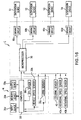
- the electronic controller E will next be explained in relation to navigation device N with reference to Fig. 1.
- the navigation device N includes a GPS sensor 30a, a vehicle speed sensor 30b and a gyro sensor 30c.
- the GPS sensor 30a detects the present position of the automobile on the basis of respective radio signals from plural geostationary satellites.
- the vehicle speed sensor 30b detects the running speed of the automobile as a vehicle speed.
- the gyro sensor 30c detects an angle of rotation of the automobile around a vertical axis passing through the center of gravity of the automobile.
- the navigation device N has an input device 30d, a memory device 30e, a computer 30f and an output device 30g.
- the input device 30d is used to input necessary information to the computer 30f.
- a series of map data is stored to the memory device 30e as a database so as to be read by the computer 30f.
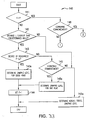
- the computer 30f executes a navigation control program in accordance with the flow charts shown in Figs. 5 to 7.
- the computer 30f executes routines required for guidance of the automobile (navigation control program) on the basis of the input from the input device 30d, the data stored in the memory device 30e and each of the outputs of the GPS sensor 30a and the vehicle speed sensor 30b.
- the output device 30g displays data required as information in the automobile, under control of the computer 30f.
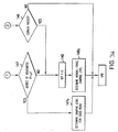
- the electronic controller E has respective acceleration sensors 41a to 41d, a steering sensor 42, a microprocessor 50 and respective driving circuits 60a to 60d.
- Each of the acceleration sensors 41 a to 41d is arranged in the vehicle body B adjacent respective suspension devices S1 to S4. Each of these acceleration sensors 41 a to 41 d detects vertical acceleration of the automobile.
- the steering sensor 42 detects a steering angle relative to a neutral position of the steering wheel of the automobile.
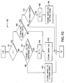
- the microprocessor 50 executes a suspension control program in accordance with the respective flow charts shown in Figs. 8 to 10 to adjust the damping force of each of the suspension devices S1 to S4 on the basis of the output of the computer 30f of the navigation device N, and the outputs of the vehicle speed sensor 30b, the gyro sensor 41e, the respective acceleration sensors 41a to 41d and the steering sensor 42.
- the respective driving circuits 60a to 60d operate the electromagnetic diaphragm valves 13 of the respective suspension devices S1 to S4 under control of the microprocessor 50.
- step 102 map data for the requested map is read from the memory device 30e.
- step 103 a routine for display of the requested map is executed, whereby the output device 30g displays the requested map on the basis of the road map data.
- a route search is executed in step 104 on the basis of the outputs of the GPS sensor 30a and the gyro sensor 41e and an input destination (input using the input device 30d).
- route guidance is provided on the basis of the results of the route search. In accordance with this guidance processing, the automobile driver is assisted in following the route determined by the route search.
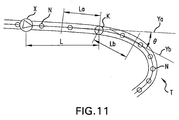
- a travel environment recognition routine 110 (see Figs. 5 and 7) is executed as follows. First, as shown in Fig. 11, it is assumed that plural nodes N show a curve around a comer T. One of these nodes shows a starting point K of the curve as a transition from a road extending in a straight line in the direction of advance of the automobile. The nodes N, included in the road map data, serve as positions for calculating a radius of curvature Ra for the comer T.
- the curve starting point K is judged as follows in step 111 of Fig. 7.
- the angle formed by straight lines Ya and Yb is calculated as a turning angle 2 at each of the nodes N in advance of the automobile.
- the straight line Ya is a straight line passing through a pair of nodes adjacent to and preceding and following a point a predetermined distance La backward from an object node K.
- the straight line Yb is a straight line passing through nodes adjacent to and preceding and following a position a predetermined distance Lb forward from the object node K.
- the first node for which the calculated turning angle 2 is greater than a predetermined angle is judged to be the curve starting point K.
- the radius of curvature Ra of the corner T is calculated for every node N as the radius of a circle passing through nodes at three points in total, including nodes at two points located before and after a node N at the comer T.
- a minimum value among the radii of curvature calculated in this way is set as radius of curvature Ra of the corner.
- step 112 When step 112 is completed, a running environment information transmission routine is executed (step 120 in Fig. 5). In this routine, information relative to the curve starting point K determined in the running environment recognition routine 110 and the radius of curvature Ra of the corner T are output to the electronic controller E.
- an acceleration signal from each of the acceleration sensors 4 1 a to 4 1 d is input to the microprocessor 50 in a step 131.
- the filter processing routine 132 involves sampling of the acceleration signal of each of the acceleration sensors 41a to 41 d input in the step 131, and extraction of an acceleration component G' at a predetermined frequency and its averaging, which are performed as follows.
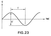
- the acceleration signal G of each of the acceleration sensors 4 1 a to 41d is sequentially sampled with the passage of time, e.g., every tenth acceleration signal from each of the acceleration sensors 41a-41d as shown in Fig. 23.
- the acceleration component G' corresponding to a predetermined frequency within the range of 10 (Hz) to 20 (Hz) is sequentially extracted from the sampling data for each of the acceleration sensors 41a-41d. All the acceleration components extracted in this way are then averaged to obtain an average acceleration component as the arithmetic mean.
- the above acceleration component determined at a frequency within the range of 10 (Hz) to 20 (Hz) because such a frequency corresponds to irregularity of a road surface which is irregular approximately to the extent of that creating discomfort for a passenger.
- the averaged acceleration component is a component common to the respective suspension devices S1 to S4 of the automobile.
- this first predetermined acceleration corresponds to that from a road surface having a worst case irregularity.
- the first predetermined acceleration is set to, e.g., 2.0 G.
- the degree of irregularity P represents the degree of irregularity of the road surface traveled by the automobile
- step 135 it is then determined in step 135 whether or not the averaged acceleration component is equal to or greater than a second predetermined acceleration.
- this second predetermined acceleration corresponds to a state less irregular than the worst case irregularity corresponding to the first predetermined acceleration, and is set to e.g., 1.0 G in this embodiment.
- step 135 When the averaged acceleration component is equal to or greater than the second predetermined acceleration, the judgement in step 135 is YES.
- step 142 the present position X of the automobile is detected on the basis of the output of the GPS sensor 30a from the computer 30f of the navigation device N. The distance L from this detected present position X of the automobile to the curve starting point K is then calculated. It is then judged whether or not this calculated distance L is less than a predetermined distance. When the distance L is not less than this predetermined distance, the judgement is NO in step 142.
- the damping level Cn is a level common for the diaphragm aperture (corresponding to an adjusting amount) of each electromagnetic diaphragm valve 13, i.e., a level corresponding to a common damping force for each of the suspension devices S1 to S4.
- step 144 determination of the damping level Cn common for the diaphragm aperture of each electromagnetic diaphragm valve 13 (corresponding to the damping force of each of the suspension devices S1 to S4) is performed as follows in step 145.
- an estimated transverse acceleration G is calculated on the basis of the vehicle speed V of the automobile and the radius of curvature Ra of the comer T by using the following formula I.
- the estimated transverse acceleration G is an estimated transverse acceleration applied to the automobile in travel of the automobile in a turn around the comer T.
- Vr a deceleration correction coefficient.
- This deceleration correction coefficient Vr is a correction coefficient for estimating and correcting the deceleration from the vehicle speed V in the present position X of the automobile to the vehicle speed during travel of the automobile around the comer.
- the above formula I is stored in a ROM of the microprocessor 50 in advance.
- the damping level Cn is determined as follows by using the estimated transverse G and the above degree of irregularity P, on the basis of map shape data given in the following Table 1.
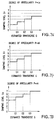
- the damping level Cn represents the relationship between the degree of irregularity P and the estimated transverse acceleration G.
- the damping level Cn is increased as the estimated transverse acceleration G increases.
- the estimated transverse acceleration G is increased as the vehicle speed of the automobile during running of the comer is increased or the radius of curvature Ra of the comer is less.
- step 146 when the automobile is found to have started turning the comer in step 146, the judgement is YES, based on the output of the steering sensor 42. Next, it is judged in step 147 whether or not the automobile has passed through the comer T, i.e., completed the turn. At the present stage, just after the judgement YES in step 146, the judgement is NO in step 147, on the basis of the output of the gyro sensor 41e from the computer 30f.
- the suspension control program proceeds to complete the damping level determination routine 140 without making a new determination of the damping level Cn in step 145.
- each electromagnetic diaphragm valve 13 of the respective suspension devices S1 to S4 is determined as follows in the next step 150 (see Fig. 8) in accordance with the result in one of the above steps 143, 145, 147 and 149.
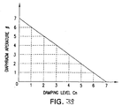
- the diaphragm aperture ⁇ is set so as to be increased (or decreased) in accordance with a reduction (or increase) in the damping level Cn.
- the damping force of each of the suspension devices S1 to S4 is controlled so as to be reduced during straight running of the automobile just before the entry into the turn around the comer T, and riding comfort (ride sensation) during travel along the straight road can be optimized, irrespective of the degree of irregularity of the road surface.
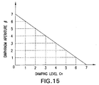
- the diaphragm aperture ⁇ is determined as follows from the ⁇ -Cn characteristics shown in Fig. 15 on the basis of the damping level Cn in step 150.
- Such a determination corresponds to that for a road surface having the worst case degree of irregularity.
- the respective electromagnetic diaphragm valves 13 greatly reduce the damping forces of the suspension devices S1 to S4.
- each electromagnetic diaphragm valve 13 greatly decreases the amount of flow of the operating oil between the hydraulic compartments 12a and 12b by increasing the resistance to circulation of the operating oil.
- each electromagnetic diaphragm valve 13 greatly increases the damping force of the respective suspension devices S1 to S4.
- step 145 when the damping level Cn is determined in step 145 after a NO determination in step 146, execution of the comer control is started. Thereafter, in straight travel, up to just before entry of the automobile into the turn at comer T, the damping force of each of the suspension devices S1 to S4 is controlled in a manner similar to the case in which the damping force is controlled by adjusting the diaphragm aperture ⁇ in step 150, after the determination YES in step 142.
- step 147 when the judgement is NO in step 147 after a YES determination in step 146, the damping level Cn already determined in step 145, just before the YES determination in step 146 is maintained.
- the damping force of each of the suspension devices S1 to S4 is controlled taking into consideration the degree of irregularity of the road surface just before the entry of the automobile into the curve around comer T and set in advance to be held and utilized as the damping force after entry of the automobile into the curve around comer T. Accordingly, when the automobile enters into the turn (curve) around comer T, the operations of the respective suspension devices S1 to S4 are estimated and controlled so as to maintain the damping force already set in advance just before entry of the automobile into the turn around the comer T. As a result, the steering stability and the ride sensation during travel of the automobile in turning the corner T can be preferably maintained even when there are irregularities in the road surface around the corner T.
- each electromagnetic diaphragm valve 13 greatly increases the flow of the operating oil between the hydraulic compartments 12a and 12b by reducing resistance to circulation of the operating oil.
- the damping force of each of the suspension devices S1 to S4 is reduced to provide a comfortable ride in straight line travel.
- Fig. 16 shows a second embodiment of the present invention in which rotational speed sensors 43a, 43b are used instead of the acceleration sensors 41a to 41d in the electronic controller E of the above first embodiment.
- Each of these rotational speed sensors 43a, 43b is arranged near a drive wheel of an axle of the automobile.
- Each of these rotational speed sensors 43a, 43b detects the rotational speed of a drive wheel.
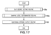
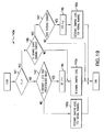
- this second embodiment is operated in accordance with the flow chart of Fig. 17, instead of the flow chart of Fig. 8 as in the first embodiment. Further, this second embodiment employs the slip degree setting routine 130a of Fig. 18 and the damping level determination routine 140a of Fig. 19, instead of the degree of irregularity setting routine 130 of Fig. 9 and the damping level determination routine 140 of Fig. 10 in the suspension control program of the first embodiment. Other features are similar to those of the first embodiment.
- the microprocessor 50 of the electronic controller E begins to execute the above suspension control program in accordance with the flow chart of Fig. 17 when execution of the navigation basic routine 100 of Fig. 5 through step 120 has been terminated.
- the suspension control program proceeds to the slip degree setting routine 130a (see Fig. 18)
- signals from the respective rotational speed sensors 43a, 43b are input to the microprocessor 50 in step 131a.
- the microprocessor 50 calculates an average value (hereinafter referred to as average rotational speed a) of the rotational speeds of the respective drive wheels on the basis of these signals.
- a slip ratio is calculated in a manner which differs depending on whether the automobile is in a driving state or in a braking state.
- driving state means that the automobile is traveling with positive acceleration in its direction of advance.
- braking state means that the automobile is running with negative acceleration with respect to its direction of advance.
- the slip ratio is calculated on the basis of the average rotational speed a and the vehicle speed V of the automobile by using the following formula II: II.
- Slip ratio ⁇ (BxDxa)-V ⁇ /(BxDxa) wherein, B is the ratio of the circumference of a circle to its diameter and D is the diameter of the drive wheel.
- step 133a a judgement is made in step 133a whether or not the slip ratio calculated in the step 132a is equal to or greater than a first predetermined slip ratio.
- this first predetermined slip ratio corresponds to that for a road surface having a worst case slip state.
- the first predetermined slip ratio is set to, e.g., 40%.
- the slip degree SP shows the degree of slip on the road surface as currently traveled by the automobile.
- step 135a a determination is made as to whether or not the slip ratio is equal to or greater than a second predetermined slip ratio.
- This second predetermined slip ratio corresponds to an un-slippery state as compared with the worst case slip state represented by the first predetermined slip ratio.
- the second predetermined slip ratio is set to, e.g., 20%.
- step 144 a determination of a damping level Cn, common to the respective suspension devices S1 to S4, is made in step 145a.
- the estimated transverse acceleration G is calculated by using formula I, on the basis of the vehicle speed V and the radius of curvature Ra of the comer T.
- the damping level Cn is determined as follows, using the estimated transverse acceleration G and the slip degree SP on the basis of map shape data of the following Table 2.
- the damping level Cn is specified by the relationship between the slip degree SP and the estimated transverse acceleration G.
- step 146 the determination of a damping level Cn common to the diaphragm apertures of all electromagnetic diaphragm valves 13 is made in step 145a as in the above case.
- step 147 a judgement is made in step 147 whether or not the automobile has completed turning the comer T as described in connection with the first embodiment, just after a judgement YES in step 146. Accordingly, similar to the first embodiment, the judgement is NO in the step 147.
- the suspension control program proceeds to the last step of the damping level determination routine 140a without newly determining the damping level Cn in step 145a.
- the diaphragm aperture of each electromagnetic diaphragm valve 13 is set in the next step 150 (see Fig. 17), in accordance with the results of one of the steps 143a, 145a, 147, 149a.
- step 145a when the damping level Cn is determined in step 145a after a judgement YES in step 142, the diaphragm aperture ⁇ is determined in step 150 on the basis of the damping level Cn from the ⁇ -Cn characteristic graph of Fig. 15.
- the electromagnetic diaphragm valves 13 greatly reduce the damping force for each of the suspension devices S1 to S4.
- the electromagnetic diaphragm valves 13 greatly increase the damping force of each of the suspension devices S1 to S4, similar to the above first embodiment.
- the damping force of each of the suspension devices S1 to S4 is reduced just before the automobile enters the turn around the comer T since the road surface has a high degree of slip, but ride comfort in straight running of the automobile can be maintained.
- step 145a when the damping level Cn is determined in step 145a after a judgement NO in step 146, execution of comer control is started. Thereafter, in straight running, until just before the automobile enters into the turn around the comer T, the damping force of each of the suspension devices S1 to S4 is controlled by adjusting the diaphragm aperture ⁇ in step 150 after a determination of YES in step 142.
- step 147 when the judgement is NO in step 147, after a judgement YES in step 146, the damping level Cn already determined in step 145a, just before the judgement YES in step 146 is maintained.
- the damping force of each of the suspension devices S1 to S4 is controlled taking into consideration the slip degree of the road surface just before entry of the automobile into the turn around the comer T and is held and utilized as the damping force after the entry of the automobile into the turn around the comer T, similar to the first embodiment.
- each of the suspension devices S1 to S4 is estimated and controlled so as to maintain the damping force already set, just before the entry of the automobile into the turn around the comer T.
- the stability and the riding comfort in the turning of the automobile around the comer T can be maximized even when the road surface at the comer T is slippery.
- the present invention provides a vehicular suspension control system for a vehicle equipped with a navigation system which control system includes:
- a good-road adjustment is calculated on a basis of a good road surface, the detected vehicle speed and the comer information, and is output to the suspension means.
- a bad-road adjustment is calculated on a basis of the detected degree of roughness, the detected vehicle speed and the comer information determined as the vehicle enters the turn at the comer, and is output to the suspension means.
- the damping force of the suspension means before entering the turn at the comer is controlled in a manner corresponding to a good-road adjustment, thus favorably maintaining steering stability of the vehicle in turning the comer.
- the damping force of the suspension means is controlled in a manner corresponding to the bad-road adjustment when entering the comer, thus, in this case also, favorably maintaining steering stability and riding comfort of the vehicle in turning the comer.
- a bad-road adjustment to the damping force of the suspension means is calculated as above and output to the suspension means. Accordingly, when the vehicle approaches a corner, in the case where the road surface changes from a degree of roughness corresponding to a good road surface to a degree of roughness not corresponding to a good road surface, the damping force of the suspension means is thereafter controlled in accordance with the bad-road adjustment amount so that, in travel around the comer, steering stability and riding comfort are maintained.
- the control system of the present invention may utilize normal travel adjustment calculating means (132, 133 - 137, 142, 143, 147, 142a, 148a) for, when the detected degree of roughness no longer corresponds to a good road surface, calculating a normal travel adjustment for damping force of the suspension means on the basis of the detected degree of roughness.
- the normal travel adjustment means may calculate the normal travel adjustment on the basis of either the detected degree of roughness alone or on the basis of the detected degree of roughness in combination with other detected condition or conditions.
- the detected degree of roughness changes from that which has the suspension means controlled in accordance with a bad-road adjustment or with a normal-travel adjustment to that corresponding to a good road surface state
- a good-road adjustment is calculated as above on the basis of the detected degree of roughness, the detected vehicle speed and the comer information, and is output to the suspension means. Accordingly, when the vehicle approaches a comer, in the case that the road surface changes from a degree of roughness not corresponding to a good road surface to a degree of roughness corresponding to a good road surface, the damping force of the suspension means is controlled in a manner corresponding to a good-road adjustment amount.
- the vehicular suspension control system of the present invention includes:
- the damping force of the suspension means is changed from that corresponding to the normal-travel adjustment to that corresponding to a bad-road adjustment.
- the above embodiment may also include the previously described good-road adjustment calculating means.
- one or all of the adjustment calculating means may extract a roughness state component at a predetermined frequency from the signal for degree of roughness output by the roughness state detecting means and calculate the adjustment for damping force of the suspension means on the basis of that roughness state component.
- the vehicular suspension control system of the present invention is installed in a vehicle also equipped with a navigation system and includes:
- a good-road adjustment is calculated on the basis of the detected slip state corresponding to the good road surface, the detected vehicle speed and the comer information, and is output to the suspension means.
- a bad-road adjustment is calculated on a basis of the detected slip, the detected vehicle speed and the comer information, responsive to a determination that the vehicle has entered the turn around the comer, and is output to the suspension means.
- the vehicle As the vehicle approaches the comer, if the slip state of the road surface changes from a slip state corresponding to a good road surface to a slip state not corresponding to a good road surface, the damping force of the suspension means is changed from that for a good road surface to that for a bad road surface when entering the comer. Thus, in travel around the comer, the vehicle maintains favorable stability.
- Those embodiments including a slip state detecting means may have a normal-travel adjustment amount calculating means (132, 133 - 137, 142, 143, 147b, 142b, 148b) for, in the case where the slip state detected by the slip state detecting means does not correspond to a good road surface, calculating a normal-travel adjustment for damping force of the suspension means on the basis of the detected slip state.
- the detected slip state may initially correspond to that of a good road surface, with control in accordance with an adjustment calculated on the basis of the detected slip state, the detected vehicle speed and the comer information.
- a normal-travel adjustment is calculated for the damping force of the suspension means on the basis of the detected slip state, and is output to the suspension means.
- a good-road adjustment is calculated for the damping force on the basis of the detected slip state, the detected vehicle speed and the comer information, and is output to the suspension means.
- the vehicular suspension control system of the present invention is installed in a vehicle also equipped with a navigation system and includes:
- the damping force of the suspension means is changed to that corresponding to a bad-road adjustment from the normal-travel adjustment.
- each of the adjustment calculating means may determine a degree of slip at a predetermined frequency from the slip state detected by the slip state detecting means and calculate the adjustment amount for damping on the basis of the determined degree of slip.
- the present invention provides a method for control of suspension means in a vehicle equipped with a navigation system, which method includes:
- the suspension means is controlled in accordance with the good-road adjustment or the bad-road adjustment, both of which are calculated on the basis of the detected degree of roughness, the detected vehicle speed and the comer information.
- the damping force of the suspension means is controlled in a manner corresponding to bad-road adjustment when entering the turn around the comer.
- the damping force of the suspension means is changed from control in accordance with the good-road adjustment to control in accordance with the normal-travel adjustment.
- control method combines the calculating and utilization of the normal-travel adjustment with calculating and utilization of the bad-road adjustment, optionally also with calculating and utilization of the good-road adjustment.
- the vehicular suspension control method of the present invention includes:
- control of the damping force of the suspension means is changed from that in accordance with the good-road adjustment to that in accordance with the bad-road adjustment.
- the calculation of a normal-travel adjustment for a detected slip state which does not correspond to a good road surface, based on the detected slip state may be included in the foregoing embodiment of the method or may be substituted for either the good-road adjustment calculation or the bad-road adjustment amount calculation.
- Fig. 24 shows one example of a suspension control system wherein suspension units S 1 - S4 are controlled by an electronic control unit E.
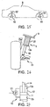
- the suspension unit S1 is interposed between a wheel support element R1, provided at a point close to the right-sided front wheel of the automobile and a corresponding portion of the frame B of the vehicle, as shown in Fig. 25.
- the wheel support element, to which the lower end of the shock absorber attaches, may be different for front and rear wheels and for different vehicles, e.g. axle housing, lower suspension arm, steering knuckle, bearing housing or motor housing.
- the suspension unit S1 has a damper 10 and a coiled spring 20, as shown in Fig. 26.
- the damper 10 at its lower end is supported on the wheel support element R1.
- the coiled spring 20 is coaxially fitted over the exterior of the damper 10, extending from a flange 10a provided at an axially intermediate point on the exterior surface of the damper 10 to the frame B. The coiled spring 20 thus biases upward the body B.
- the structure and function of the damper 10 is illustrated by the schematic circuit shown in Fig. 27.
- the damper 10 has a piston 11 and a hydraulic cylinder 12.
- the piston 11 is axially slidably received within the cylinder 12, and partitions the interior of the cylinder 12 into upper and lower hydraulic chambers 12a, 12b.
- the damper 10 also has an electromagnetic reduction valve 13.
- the electromagnetic reduction valve 13 allows for communication between hydraulic chambers 12a, 12b in accordance with the size of a variable opening therein.
- a piston rod 14 extends from the piston 11 through the hydraulic chamber 12a and its upper end is coupled to the frame B.
- the electromagnetic reduction valve 13 regulates the amount of flow of operating oil between the hydraulic chambers 12a, 12b, according to the size of its opening. As the opening of the electromagnetic reduction valve 13 is decreased (or increased) the resistance to flow of operating oil through the electromagnetic reduction valve 13 is increased (or decreased) with a corresponding change to damping force of the damper 10 and ultimately the suspension S 1.
- the suspension unit S2 is interposed between a wheel support element R2 provided at a point close to the right-side rear wheel of the automobile and a corresponding point on the frame B.
- the suspension unit S3 (see Fig. 24) is interposed between a wheel support frame at a point close to the left-sided rear wheel of the automobile and a corresponding point on the frame B.
- the suspension unit S4 (see Fig. 24) is interposed between a wheel support element at a point close to the left-side rear wheel and a corresponding point on the frame B.
- suspension units S2 - S4 respectively have dampers 10 and coiled springs 20, similar to the suspension unit S1.
- the suspension unit S2 - S4 function similar to the suspension unit S1, owing to the damper 10 and the coiled spring 20.
- the front wheels of the automobile are the drive wheels in the illustrated embodiment.
- the navigation system N has a GPS sensor 30a, a gyro sensor 30b and a vehicle speed sensor 30c.
- the GPS sensor 30a detects a current position of the automobile, on the basis of the radio signals from a plurality of stationary satellites.
- the gyro sensor 30b detects an angle of rotation of the automobile about a perpendicular axis passing the center of gravity of the automobile.
- the vehicle-speed sensor 30c detects traveling speed of the automobile.
- the navigation system N has an input unit 30d, a storage unit 30e, a computer 30f and an output unit 30g.
- the input unit 30d is operable to input required information into the computer 30f.
- the storage unit 30e is stored with, as a database, serial map data to be read out by the computer 30f.
- the computer 30f executes a navigation control program according to the flowcharts shown in Figs. 28 to 30.
- the computer 30f during execution of the navigation control program, provides route guidance for the driver, on the basis of information from the input unit 30d, data stored in the storage unit 30e, and outputs of the GPS sensor 30a, gyro sensor 30b and vehicle-speed sensor 30c.
- the output unit 30g displays information required for guidance of the automobile, under control of the computer 30f.
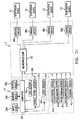
- the electronic control unit E has acceleration sensors 41a - 41d, a steering sensor 42, a microprocessor 50, and drive circuits 60a - 60d, as shown in Fig. 24.
- the acceleration sensors 41a - 41d are respectively provided on the frame B, at positions close to the suspension units S1 - S4. These acceleration sensors 41 a - 41 d respectively detect acceleration G acting vertically on the automobile.
- the steering sensor 42 detects a steering angle as angle of rotation from a neutral position to a steering direction of the steering wheel.
- the microprocessor 50 executes a suspension control program, according to the flowcharts shown in Figs. 31 to 34.
- the microprocessor 50 determines a damping force for each suspension unit S 1 - S4, on the basis of input from the computer 30f of the navigation system N and from the vehicle-speed sensor 30c, acceleration sensors 41 a - 4 1 d and steering sensor 42.
- the drive circuits 60a - 60d drive the electromagnetic reduction valves 13 of the suspension units S1 - S4, under control of the microprocessor 50.
- step 101 determines whether a request is made for a desired map by operation of the input unit 30d. If a request is made for a desired map by operation of the input unit 30d, the determination in step 101 (Fig. 29) is YES. Then, in step 102, map data for the desired map is read out of the storage unit 30e. Thereafter, the desired map is displayed by the output unit 30g on the basis of the map data.
- a route search is executed.
- This route search utilizes outputs of the GPS sensor 30a and gyro sensor 30b and destination input through the input unit 30d.
- route guidance is provided for the automobile, based on the results of the route search, assisting the driver in following the guidance route determined by search.
- a travel-environment recognition routine 110 (see Figs. 28 and 30) is executed as in the following manner. It is first assumed, as shown in Fig. 35, that a point has been set (hereinafter, curve starting point K) at which the road traveled starts to curve at a curve angle T with a straight road in the traveling direction of the automobile (hereinafter, also referred to as comer T). A plurality of nodes N, included in the map data are utilized as reference points for calculating the radius of curvature Ra of the comer T.
- the curve starting point K is determined as follows. Firstly, an angle defined between a straight line Ya and a straight line Yb is calculated as a cornering angle ⁇ , for each node present in the direction of travel of the automobile, as shown in Fig. 35.
- the straight line Ya is a straight line passing between nodes adjacent a point a predetermined distance La backward from the subject node (a node for which cornering angle ⁇ is to be calculated (here (K)).
- the straight line Yb is a straight line passing between nodes adjacent a point a predetermined distance Lb forward from the subject node.
- the first node for which a cornering angle ⁇ is greater than a predetermined angle is taken as the curve starting point K.
- the radius of curvature Ra of the comer T is calculated for each node N, as a radius of a circle passing through three points in total, including the two nodes positioned immediately forward and backward of the subject node N.
- the minimum of the radii of curvature thus calculated, is taken as the radius of curvature Ra of the corner T.
- a travel-environment information routine is executed as step 120 in Fig. 28.
- the electronic control unit E obtains information for the curve starting point K determined in the travel-environment recognition routine 110 and the radius of curvature Ra of the comer T.
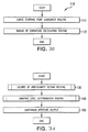
- the microprocessor 50 of the electronic control unit E executes the roughness-degree setting routine 130 of Fig. 32 (step 130 in the flowchart of Fig. 31) utilizing the acceleration signals from the acceleration sensors 41a - 41 d input in step 131.
- step 132 a filter routine is executed.
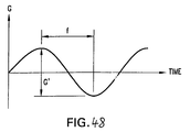
- the acceleration signals are sampled, acceleration components G' at a predetermined frequency are extracted and the extracted acceleration components are averaged. See Fig. 48.
- the acceleration signals are sampled chronologically in order, e.g. ten at one time, from each of the acceleration sensors 41 a-41 d, in sequence.
- acceleration components corresponding to a frequency within a range of 10 (Hz) - 20 (Hz) are extracted from the sampling data of the acceleration sensors 41 a-41 d, in sequence. All the acceleration components thus extracted are averaged to obtain an average acceleration component as an arithmetic mean.
- the reason for taking acceleration components corresponding to a frequency in the range of 10 (Hz) - 20 (Hz) is because of correspondence of such frequencies to a degree of roughness of the traveled road surface which is uncomfortable for the occupants.
- the above average acceleration component is a component averaged for the suspension units S 1 - S4 of the automobile.
- the first predetermined acceleration corresponds to the worst degree of roughness of the travelled road surface, which in this embodiment is set at 2.0 G, for example.
- the determination at step 133 is YES.
- the second predetermined acceleration corresponds to a moderate state of roughness rather than the worst case roughness state corresponding to the first predetermined acceleration, which in this embodiment is set at 1.0 G, for example.
- the determination is YES in step 135.
- step 142 a current position X of the automobile is obtained from the computer 30f of the navigation system N, based on output of the GPS sensor 30a. The distance L from the detected current position X of the automobile to the curve starting point K is calculated and a determination is made as to whether or not the calculated distance L is less than a predetermined distance. If the calculated distance L is not less than the predetermined distance, the determination in step 142 is NO.
- the damping level Cn is a level common for the aperture openings of the electromagnetic reduction valves 13 and which corresponds to the damping force of the suspension unit S 1 - S4.
- estimated lateral G is calculated on the basis of the vehicle speed V and the radius of curvature Ra of a comer T, by use of the following Equation I.
- estimated lateral G is a horizontal estimated acceleration that the automobile will undergo upon turning the comer T.
- the Equation I is stored in the ROM of the microprocessor 50.
- the data of Table 1 is prestored in the ROM of the microprocessor 50, together with the data map of table 2 referred to later.
- the damping level Cn increases with increase in estimated lateral G, as shown in Fig. 36. Further, as the speed V of the automobile turning the comer becomes higher and as the radius of curvature Ra of the comer T becomes smaller, the estimated lateral G becomes greater.
- step 145 when the automobile has commenced cornering, the determination is YES, on the basis of the signal output by the steering sensor 42. Then, in step 145a, a process of determining a damping level Cn common to the suspension units S1 - S4, is executed as follows.
- an estimated lateral G is calculated on the basis of vehicle speed V of the automobile and radius of curvature Ra of the corner T, by use of the foregoing Equation I.
- Damping level Cn is determined by use of an estimated lateral G and the degree of roughness P, as follows, on the basis of the data map shown in Table 2 below.
- damping level Cn is specified in relation to degree of roughness P and estimated lateral G.
- damping level Cn is specified to increase with increase in the estimated lateral G, as shown in Figs. 37 and 38.
- step 147a a damping level Cn common to the suspension units S1 - S4 is determined by applying an estimated lateral G to the data map of Table 1, similar to step 143a.
- step 146 if the automobile has commenced cornering, the determination is YES on the basis of the output of the steering sensor 42. Then, in step 149 of Fig. 34, it is determined whether or not the automobile has passed the comer T. Immediately after the determination YES in step 146, a determination NO is made in step 149 on the basis of output of gyro sensor 30b from the computer 30f.
- the suspension control program proceeds to the end of the damping-level determination routine 140 without determining a new damping level Cn.
- the damping level Cn is then held until a determination of YES in step 149.
- step 150 the electromagnetic reduction valves 13 of the suspension units S1 - S4 have their apertures adjusted in accordance with the damping level determined in step 142a (or 148a), 143a (or 147a) or 145a or by NO in step 149.
- each electromagnetic reduction valve 13 greatly increases the amount of flow of operating oil between the hydraulic chambers 12a, 12b, thereby greatly reducing the resistance to flow of operating oil. In this manner, when the automobile is traveling straight at a point further from the comer T than the predetermined value, the damping force of the suspension unit S 1 - S4 is made smaller with emphasis on driving comfort, in a manner suited for the normal travel of the automobile.
- the aperture opening ⁇ thus determined is output as data in step 150 to the drive circuits 60a - 60d. Based on the output, the damping force of each suspension unit S 1 - S4 is controlled as follows.
- the damping level Cn is determined in step 147a on the basis of a procedure similar to that of step 143a. Accordingly, even in further straight travel of the automobile after the distance L to the comer T has become less than the predetermined distance, the damping force of each suspension unit S1 - S4 can be changed to place more emphasis on steering stability immediately before entering the turn around the comer. Moreover, because the road surface is at the most moderate degree of roughness, the automobile is comfortable to drive during straight travel after the distance L to the comer T has become less than the predetermined distance.
- the aperture opening ⁇ thus determined is output as data in step 150 to the drive circuits 60a - 60d. Based on the output data, the damping force of each suspension unit S1 - S4 is controlled as follows.
- the damping force of the suspension units S 1 - S4 is adjusted during straight travel of the automobile and is thereby under control immediately upon commencing cornering (see YES in step 145), whereby the damping force of the suspension units S 1 - S4 is controlled in accordance with a determined damping level (determined aperture opening ⁇ ) in step 145a.
- the determination routine of step 149 is then initiated and, when the determination in step 149 is NO, the damping level Cn which has already been determined in step 143a (or 147a) or 145a is maintained.
- the most currently determined damping level Cn i.e. the damping level Cn immediately before entering the turn at the comer T, is maintained as determined in step 143a or 45a in a previously executed cycle.
- a suitable damping force for each suspension unit S 1 - S4 is predicted and set in advance, taking into consideration the degree of roughness of the road surface as detected immediately before or immediately after entering the turn at the comer T of the automobile, in order to hold and utilize that damping force during cornering at the comer T by the automobile.
- the suspension units S1 - S4 are controlled with a damping force previously set immediately before or immediately after entering the turn at comer T.
- a damping force previously set immediately before or immediately after entering the turn at comer T.
- Fig. 40 shows a second embodiment of the invention.
- This second embodiment employs rotational speed sensors 43a, 43b as shown in Fig. 40 in place of the acceleration sensors 41a - 41d of the first embodiment.
- These rotational speed sensors 43a, 43b are respectively provided in positions close to the driving wheels of the automobile to detect rotational speeds of the respective drive wheels.
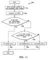
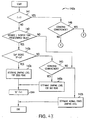
- the second embodiment utilizes the control program represented by the flowchart of Fig. 41, instead of the program of the flowchart of Fig. 31 in the first embodiment. Further, the second embodiment utilizes the slip-degree setting routine 130a of Fig. 42 and the damping-level determination routine 140a of Figs. 43 and 44, instead of the roughness-degree setting routine 130 of Fig. 31 and damping-level determination routine 140 of Figs. 33 and 34, utilized in the first embodiment.
- the microprocessor 50 of the electronic control unit E starts to execute the suspension control program in accordance with the flowchart of Fig. 41.
- mean rotational speed a a mean value for rotational speed of the drive wheels
- a slip ratio is calculated in one of two manners, depending on whether the automobile is in a driven state or in a brake-applied state.
- a driven state means that the automobile is traveling with a positive acceleration relative to the direction of travel.
- a "brake-applied state” means that the automobile is traveling with a negative acceleration relative to the direction of travel.
- Equations II and III are prestored in the ROM of the microprocessor 50.
- step 133a it is determined in step 133a whether or not the slip ratio calculated is step 132a is equal to or greater than a first predetermined slip ratio.
- the first predetermined slip ratio corresponds to the worst slip state of the road surface, which, in the present embodiment, is set at 40%, for example.
- step 135a it is determined in step 135a whether or not the slip ratio is equal to or greater than a second predetermined slip ratio.
- the second predetermined slip ratio corresponds to a state less slippery than the worst slip state corresponding to the first predetermined slip ratio, which in the present embodiment is set at 20%, for example.
- step 142 it is determined whether or not the distance L, calculated in a manner similar to step 142 (see Fig. 33) in the first embodiment, is less than the predetermined distance.
- step 142 becomes YES when the distance L becomes less than the predetermined distance.
- step 143c determination of a damping level Cn common to the suspension units S 1 - S4 is executed as follows.
- an estimated lateral G is calculated based on the speed V of the automobile and the radius of curvature Ra of the comer T, by use of the foregoing Equation 1.
- the data map of Table 3 may be prestored in the ROM of the microprocessor 50, together with the data map of Table 4 below.
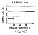
- damping level Cn increases with increasing estimated lateral G as shown in Fig. 45.
- step 145 if the automobile has commenced cornering, the determination is YES based on the output of the steering sensor 42. Then, in step 145b, a determination of a damping level Cn common to the suspension units S 1 - S4 is executed as follows.
- an estimated lateral G is calculated based on the speed V of the automobile and the radius of curvature Ra of the comer T, by use of the foregoing Equation I.
- Damping level Cn is determined based on the data map shown in Table 4 below, by use of the estimated lateral G and the foregoing degree of slip SP, as follows.
- damping level Cn is specified in relationship with degree of slip SP and estimated lateral G.
- damping level Cn increases with increasing estimated lateral G in the relationship between a damping level Cn and an estimated lateral G, as shown in Figs. 46 and 47.
- step 147b a damping level Cn common to the suspension units S1 - S4 is determined by using an estimated lateral G on the basis of the data map of Table 3, similar to step 143c.
- step 146 if the automobile has commenced cornering, the determination is YES based on output of the steering sensor 42. Then, in step 149 of Fig. 44, it is determined whether or not the automobile has passed the comer T, similar to the first embodiment. Immediately after a determination of YES in step 146, the determination NO is made in step 149, similar to the first embodiment, on the basis of output of gyro sensor 30b from the computer 30f.
- the suspension control program proceeds to the end step of the damping-level determination routine 140a without newly determining a damping level Cn.
- step 149 the determination becomes YES in step 149, similar to the first embodiment.
- each suspension unit S 1 - S4 is decreased so as to emphasize behavior stability suited for normal travel, when the automobile is traveling straight at a point further from the comer T than the predetermined value.
- the degree of opening ⁇ thus determined is output as data in step 150 to the drive circuits 60a - 60d. Based on this output data, the damping force of each suspension unit S1 - S4 is controlled as follows.
- electromagnetic reduction valves 13 greatly increase the damping forces of the suspension unit S1 - S4, similar to the first embodiment.
- damping level Cn is determined in step 147c in a manner similar to the determination in step 143c. Accordingly, even in straight travel of the automobile after the distance L to the comer T has become less than the predetermined distance, control of the damping force of each suspension unit S1 - S4 can be changed to place emphasis on steering stability in cornering immediately before entering the turn around the comer. Moreover, because the road surface is in the least slidable state, the automobile has good stability during straight travel of the automobile after the distance L to the comer T becomes less than the predetermined distance.
- the aperture opening ⁇ thus determined is output as data in step 150 to the drive circuits 60a - 60d. Based on this output data, the damping force of each suspension unit S1 - S4 is controlled as below.
- step 149 after a YES determination in step 146, following execution of steps 143b, 143c and 144, the most currently determined damping level Cn, i.e. the damping level Cn immediately before entering the turn at the comer T, is maintained in step 143c.
- step 145b the most recently determined damping level Cn, i.e. the damping level Cn immediately after entering the turn at comer T, is maintained in step 145b.
- each suspension unit S1 - S4 is predicted and controlled in advance, taking into consideration the degree of slip of the road surface immediately before or immediately after entering the turn at the comer T, which damping force is held and utilized throughout cornering at the comer T.
- the suspension units S1 - S4 are controlled with a damping force previously set immediately before or immediately after entering the turn at the comer T. As a result, even if there is a slip in the road surface at the comer T, it is possible to maintain stability in turning the comer T.
Abstract
Description
- The present invention relates to a suspension control system and to a suspension control method for a vehicle.
- JP-A-9-114367 discloses a suspension control system in which the suspension is adjusted in advance, for example, just before the vehicle starts to turn a comer in traveling a predetermined route, on the basis of the speed of the vehicle and comer information obtained from a navigation device within the vehicle.
- However, in the suspension control system of JP-A-9-114367, the comer information obtained from the navigation device includes no information relative to the state of the road surface at the comer. Accordingly, for example, when the road surface at the comer is irregular and/or slippery, steering during travel of the vehicle around the comer may become unstable and the driver may feel riding discomfort (an unpleasant sensation).
- Therefore, in order to overcome the above problem, an object of the present invention is to provide a suspension control system and a suspension control method for a vehicle in which the operation of a suspension means in running the vehicle is controlled by also taking into consideration the state of the road surface traveled by the vehicle, in addition to the information relative to the comer from the navigation device when the vehicle approaches the comer.
- Appended
claim 1 is directed towards a suspension control system providing a solution for the object of the invention. - Appended
claim 7 is directed towards a suspension control method providing a solution for the object of the invention. - Appended sub-claims are directed towards advantageous embodiments of their respective independent claims.
- In a first aspect, the present invention provides a suspension control system which includes:
- suspension means (S1 to S4) interposed and mounted between suspension arm (R1, R2) and the body (B) of the vehicle mounting a navigation device (N), and operated in accordance with a controlled damping force;
- irregular state detecting means (41a to 41d) for detecting the degree of irregularity of a road surface on which the vehicle is running;
- vehicle speed detecting means (30b) for detecting the running speed of the vehicle as a vehicle speed;
- calculating means (132, 133 to 137, 141, 142, 144, 145) for calculating an adjustment value corresponding to the damping force of the suspension means on the basis of the detected vehicle speed (V), the detected degree of irregularity and information relative to a comer (T) from the navigation device, when the vehicle approaches the comer (T) during travel; and
- output means (150, 60a to 60d) for outputting the above adjustment value to the suspension means so as to control the damping force of the suspension means in accordance with the calculated adjustment value.
-
- Thus, when the vehicle approaches the comer, an adjustment value corresponding to a desirable damping force of the suspension means is calculated on the basis of the detected vehicle speed, the detected irregularity and the information relative to the comer from the navigation device. The adjustment value is output to the suspension means so as to control the damping force of the suspension means by the adjustment value.
- Accordingly, a good ride sensation (riding comfort of the passengers) and good steering stability during the running of the vehicle can be maintained even when there are irregularities in the road surface approaching and/or in the comer.
- In accordance with a second aspect of the invention, the suspension control system may further include:
- turning detecting means (42) for detecting turning of the vehicle; and
- entry judging means (146) for judging whether or not the vehicle has entered into a turn around the comer, on the basis of the detected turning of the vehicle; and wherein the output means outputs the above adjustment value to the suspension means so as to control its damping force in accordance with the adjustment value from the calculating means and in accordance with the judgment of the entry judging means.
-
- In accordance with a third aspect of the present invention, the calculating means preferably extracts an irregularity component corresponding to a predetermined frequency from the degree of irregularity detected by the irregular state detecting means, and calculates the adjustment value corresponding to the damping force of the suspension means on the basis of the irregularity component extracted in this way. The operating advantages of the invention previously described can be further improved by calculating the adjustment value in this manner.
- In accordance with a fourth aspect of the invention, the calculating means stops the calculation of the adjustment value responsive to a determination by the entry judging means that the vehicle has started the turn around the comer, and the calculating means reports the adjustment value at this point in time (start of turn) as the adjustment value for the damping force of the suspension means to be used for turning the comer.
- In accordance with a fifth aspect of the invention, the suspension control system for a vehicle in the present invention comprises:
- suspension means (S1 to S4) interposed and mounted between a suspension arm (R1, R2) and the body (B) of the vehicle mounting a navigation device (N), and operated in accordance with a controlled damping force;
- slip state detecting means (43a, 43b) for detecting the slip state of a road surface at the present location (position) of the vehicle;
- vehicle speed detecting means (30b) for detecting the running speed of the vehicle as a vehicle speed;
- calculating means (132a, 133a to 137a, 141, 142, 144, 145a) for calculating an adjustment value (amount) corresponding to a preferred level of damping force of the suspension means on the basis of the detected vehicle speed (V), the detected slip state and information relative to a comer (T) from the navigation device, when the vehicle approaches the comer (T) during travel; and
- output means (150, 60a to 60d) for outputting the adjustment value to the suspension means so as to control the damping force of the suspension means in accordance with the calculated adjustment value.
-
- Thus, when the vehicle approaches a comer during travel, the adjustment value corresponding to the damping force of the suspension means is calculated on the basis of the detected vehicle speed, the detected slip state and the information relative to the comer from the navigation device. The above adjustment value is output to the suspension means so as to control the damping force of the suspension means in accordance with the calculated adjustment value.
- Accordingly, riding comfort and stability during travel can be maintained in a preferred manner even when the road surface state approaching the comer and the road surface within the comer are slippery.
- Further, in accordance with a sixth aspect of the invention, the suspension control system of the fifth aspect further comprises:
- turning detecting means (42) for detecting turning of the vehicle;
- entry judging means (146) for determining whether or not the vehicle has entered into the turn around the comer on the basis of the determination made by the turning detecting means; and wherein the output means outputs the adjustment value to the suspension means so as to control the damping force of the suspension means in accordance with adjustment value and in accordance with the determination of the entry judging means that the vehicle has entered into the turn around the comer.
-
- Further, in accordance with another aspect of the invention, the calculating means determines a predetermined slip state based on the slip state detected by the slip state detecting means, and calculates the adjustment value corresponding to the damping force of the suspension means on the basis of the slip state.
- In another embodiment, the calculating means calculates an adjustment value corresponding to damping force of the suspension means on the basis of both the state of the road surface detected for the present position of the vehicle and information relative to the comer which is output from the navigation device, and the damping force of the suspension means during travel of the vehicle is controlled in accordance with this calculated adjustment value.
-
- Fig. 1
- is a block diagram of a first embodiment of a suspension control system for an automobile in accordance with the present invention.
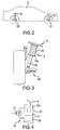
- Fig. 2
- is a schematic view showing arrangement of suspension devices in the automobile.
- Fig. 3
- is an enlarged side view of one suspension device of Fig. 2.
- Fig. 4
- is a schematic view of a circuit of the suspension device.
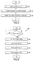
- Fig. 5
- is a flow chart of a navigation control program executed by a computer of the navigation device of Fig. 1.
- Fig. 6
- is a detailed flow chart of the basic navigation routine (
step 100 in Fig. 5). - Fig. 7
- is a flow chart of the running environment recognition routine (
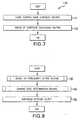
step 110 in Fig. 5). - Fig. 8
- is a flow chart of a suspension control program executed by the microprocessor of the electronic controller in Fig. 1.
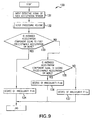
- Fig. 9
- is a flowchart of the degree of irregularity setting routine (
step 130 in Fig. 8). - Fig. 10
- is a flow chart of the damping level determination routine (
step 140 in Fig. 8). - Fig. 11
- is a schematic view of a road including a curve starting point.
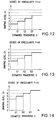
- Fig. 12
- is a graph of the relationship between damping level Cn and an estimated transverse acceleration G, as shown by a degree of irregularity P=Hi in the first embodiment.
- Fig. 13
- is a graph of the damping level Cn versus the estimated transverse acceleration G, as shown by a degree of irregularity P=Mi in the first embodiment.
- Fig. 14
- is a graph of the damping level Cn versus the estimated transverse acceleration G, as shown by a degree of irregularity P=Lo in the first embodiment.
- Fig. 15
- is a graph showing the relationship between the
diaphragm aperture 3 of an electromagnetic diaphragm valve and the damping level Cn. - Fig. 16
- is a block diagram of a second embodiment of the present invention.
- Fig. 17
- is a flow chart of a suspension control program executed by a microprocessor of the electronic controller in Fig. 16.
- Fig. 18
- is a flow chart of the degree of slip setting routine (
step 130a in Fig. 17). - Fig. 19
- is a flow chart of the damping level determination routine (
step 140a in Fig. 17). - Fig. 20
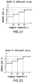
- is a graph showing the relationship between the damping level Cn and the estimated transverse acceleration G for a degree of slip SP=Hi in the second embodiment.
- Fig. 21
- is a graph of the damping level Cn versus the estimated transverse acceleration G for a degree of slip SP=Mi in the second embodiment.
- Fig. 22
- is a graph of the damping level Cn versus the estimated transverse acceleration G for a degree of slip SP=Lo in the second embodiment.
- Fig. 23
- is a graph of detected acceleration G versus time, showing frequency f and the acceleration component G'.
- Preferred embodiments of the present invention will next be explained with reference to the drawings.
- Fig. 1 shows a first embodiment of a suspension control system of the present invention, designed for a sedan type automobile and including
suspension devices S 1 to S4 and an electronic controller E. - As shown in Fig. 2, the suspension device S1 is interposed and mounted between a wheel support element R1 supporting the right-hand side front wheel of the automobile, and the right-hand side front portion of the vehicle frame B.
- As shown in Fig. 3, this suspension device S1 has a
damper 10 and acoil spring 20. The lower end portion ofdamper 10 is supported on-the wheel support element. The wheel support element, to which the lower end of the shock absorber attaches, may be different for front and rear wheels and for different vehicles, e.g., axle housing, lower suspension arm, steering knuckle, bearing housing or motor housing. Thecoil spring 20 is coaxially mounted on thedamper 10, external thereto, between a flange 10a arranged in an axially intermediate location on thedamper 10 and the vehicle frame B. Thus, thecoil spring 20 biases upward the front right-hand side of the vehicle frame B. - The construction and function of the
damper 10 is illustrated by the equivalent circuit shown in Fig. 4 which shows thedamper 10 as including apiston 11 and ahydraulic cylinder 12. Thepiston 11 is slidably fitted and mounted within thecylinder 12, and partitions the interior of thecylinder 12 into upper and lowerhydraulic compartments 12a, 12b. - Further, the
damper 10 has anelectromagnetic diaphragm valve 13 which provides communication betweenhydraulic compartments 12a and 12b through its diaphragm aperture. Apiston rod 14 extends from thepiston 11 through the hydraulic compartment 12a and its upper end is connected to the vehicle body B at the right-hand side front wheel corresponding part. - As the
piston 11 slides upward within thedamper 10, operating oil within the hydraulic compartment 12a flows into thehydraulic compartment 12b through theelectromagnetic diaphragm valve 13. Likewise, as thepiston 11 slides downward, the operating oil within thehydraulic compartment 12b flows into the hydraulic compartment 12a through theelectromagnetic diaphragm valve 13. In this embodiment, theelectromagnetic diaphragm valve 13 adjusts the amount of flow of the operating oil between thehydraulic compartments 12a and 12b, in accordance with its diaphragm aperture which is reduced (or increased) in accordance with an increase (or decrease) corresponding to the damping force of thedamper 10, i.e., the damping force of the suspension device S1. - Likewise, the suspension device S2 is interposed and mounted between a wheel support element R2, arranged near the right-hand side rear wheel of the automobile, and the corresponding part (hereinafter also called the right-hand side rear wheel corresponding part) of the vehicle frame B. The suspension device S3 (see Fig. 1) is interposed and mounted between an unillustrated wheel support element, supporting the left-hand side front wheel of the automobile and the corresponding part of the vehicle frame B. Further, the suspension device S4 (see Fig. 1) is interposed and mounted between an unillustrated wheel support element supporting the left-hand side rear wheel of the automobile and the corresponding part of the vehicle frame B.
- Similar to the suspension device S1, each of these suspension devices S2 to S4 has a
damper 10 andcoil spring 20 and each functions in a manner similar to suspension device S1. - The front wheels of the automobile serve as the drive wheels.
- The electronic controller E will next be explained in relation to navigation device N with reference to Fig. 1. The navigation device N includes a
GPS sensor 30a, avehicle speed sensor 30b and agyro sensor 30c. TheGPS sensor 30a detects the present position of the automobile on the basis of respective radio signals from plural geostationary satellites. Thevehicle speed sensor 30b detects the running speed of the automobile as a vehicle speed. Thegyro sensor 30c detects an angle of rotation of the automobile around a vertical axis passing through the center of gravity of the automobile. - Further, the navigation device N has an
input device 30d, amemory device 30e, acomputer 30f and anoutput device 30g. Theinput device 30d is used to input necessary information to thecomputer 30f. A series of map data is stored to thememory device 30e as a database so as to be read by thecomputer 30f. - The
computer 30f executes a navigation control program in accordance with the flow charts shown in Figs. 5 to 7. Thecomputer 30f executes routines required for guidance of the automobile (navigation control program) on the basis of the input from theinput device 30d, the data stored in thememory device 30e and each of the outputs of theGPS sensor 30a and thevehicle speed sensor 30b. Theoutput device 30g displays data required as information in the automobile, under control of thecomputer 30f. - As shown in Fig. 1, the electronic controller E has
respective acceleration sensors 41a to 41d, asteering sensor 42, amicroprocessor 50 andrespective driving circuits 60a to 60d. - Each of the
acceleration sensors 41 a to 41d is arranged in the vehicle body B adjacent respective suspension devices S1 to S4. Each of theseacceleration sensors 41 a to 41 d detects vertical acceleration of the automobile. Thesteering sensor 42 detects a steering angle relative to a neutral position of the steering wheel of the automobile. - The
microprocessor 50 executes a suspension control program in accordance with the respective flow charts shown in Figs. 8 to 10 to adjust the damping force of each of the suspension devices S1 to S4 on the basis of the output of thecomputer 30f of the navigation device N, and the outputs of thevehicle speed sensor 30b, the gyro sensor 41e, therespective acceleration sensors 41a to 41d and thesteering sensor 42. - The
respective driving circuits 60a to 60d operate theelectromagnetic diaphragm valves 13 of the respective suspension devices S1 to S4 under control of themicroprocessor 50. - In this first embodiment, when the
computer 30f of the navigation device N starts the execution of the navigation control program in accordance with the flow chart of Fig. 5, basic guidance is provided by the navigation device N by execution of a basic navigation routine 100 (see Fig. 6). - First, if request for display of a map is made by operation of the
input device 30d, the judgement is YES instep 101 of Fig. 6. Next, instep 102, map data for the requested map is read from thememory device 30e. Thereafter, instep 103, a routine for display of the requested map is executed, whereby theoutput device 30g displays the requested map on the basis of the road map data. - Next, a route search is executed in
step 104 on the basis of the outputs of theGPS sensor 30a and the gyro sensor 41e and an input destination (input using theinput device 30d). Instep 105, route guidance is provided on the basis of the results of the route search. In accordance with this guidance processing, the automobile driver is assisted in following the route determined by the route search. - When the execution of the
basic navigation routine 100 is completed, a travel environment recognition routine 110 (see Figs. 5 and 7) is executed as follows. First, as shown in Fig. 11, it is assumed that plural nodes N show a curve around a comer T. One of these nodes shows a starting point K of the curve as a transition from a road extending in a straight line in the direction of advance of the automobile. The nodes N, included in the road map data, serve as positions for calculating a radius of curvature Ra for the comer T. - The curve starting point K is judged as follows in
step 111 of Fig. 7. First, as shown in Fig. 11, the angle formed by straight lines Ya and Yb is calculated as aturning angle 2 at each of the nodes N in advance of the automobile. Here, the straight line Ya is a straight line passing through a pair of nodes adjacent to and preceding and following a point a predetermined distance La backward from an object node K. Further, the straight line Yb is a straight line passing through nodes adjacent to and preceding and following a position a predetermined distance Lb forward from the object node K. - When the
turning angle 2 is calculated for every node N as mentioned above, the first node for which the calculated turningangle 2 is greater than a predetermined angle is judged to be the curve starting point K. - Next, in
step 112, the radius of curvature Ra of the corner T is calculated for every node N as the radius of a circle passing through nodes at three points in total, including nodes at two points located before and after a node N at the comer T. Here, a minimum value among the radii of curvature calculated in this way is set as radius of curvature Ra of the corner. - When
step 112 is completed, a running environment information transmission routine is executed (step 120 in Fig. 5). In this routine, information relative to the curve starting point K determined in the runningenvironment recognition routine 110 and the radius of curvature Ra of the corner T are output to the electronic controller E. - In execution of the degree of irregularity setting routine 130 (see Fig. 9) by the
microprocessor 50 of the electronic controller E, in the first routine in the suspension control program shown in Fig. 8, an acceleration signal from each of theacceleration sensors 4 1 a to 4 1 d is input to themicroprocessor 50 in a step 131. - The
filter processing routine 132 involves sampling of the acceleration signal of each of theacceleration sensors 41a to 41 d input in the step 131, and extraction of an acceleration component G' at a predetermined frequency and its averaging, which are performed as follows. - Namely, in the sampling, the acceleration signal G of each of the
acceleration sensors 4 1 a to 41d is sequentially sampled with the passage of time, e.g., every tenth acceleration signal from each of theacceleration sensors 41a-41d as shown in Fig. 23. On the basis of the data sampled in this way, the acceleration component G' corresponding to a predetermined frequency within the range of 10 (Hz) to 20 (Hz) is sequentially extracted from the sampling data for each of theacceleration sensors 41a-41d. All the acceleration components extracted in this way are then averaged to obtain an average acceleration component as the arithmetic mean. - In this embodiment, the above acceleration component determined at a frequency within the range of 10 (Hz) to 20 (Hz) because such a frequency corresponds to irregularity of a road surface which is irregular approximately to the extent of that creating discomfort for a passenger. The averaged acceleration component is a component common to the respective suspension devices S1 to S4 of the automobile.
- Next, it is judged in
step 133 whether or not the above averaged acceleration component is equal to or greater than a first predetermined acceleration. Here, this first predetermined acceleration corresponds to that from a road surface having a worst case irregularity. In this embodiment, the first predetermined acceleration is set to, e.g., 2.0 G. - When the averaged acceleration component is greater than the first predetermined acceleration, the judgement in
step 133 is YES and the degree of irregularity P=Hi is set instep 134. Here, the degree of irregularity P represents the degree of irregularity of the road surface traveled by the automobile, and a degree of irregularity P=Hi indicates that the road surface traveled by the automobile is a worst case degree of irregularity. - When the judgment in
step 133 is NO, it is then determined instep 135 whether or not the averaged acceleration component is equal to or greater than a second predetermined acceleration. Here, this second predetermined acceleration corresponds to a state less irregular than the worst case irregularity corresponding to the first predetermined acceleration, and is set to e.g., 1.0 G in this embodiment. - When the averaged acceleration component is equal to or greater than the second predetermined acceleration, the judgement in
step 135 is YES. Next, a degree of irregularity P=Mi is set instep 136. Here, degree of irregularity P=Mi indicates that the degree of irregularity of the road surface traveled by the automobile is a degree gentler than the worst case degree of irregularity corresponding to P=Hi. - When the judgment in
step 135 is NO, a degree of irregularity P=Lo is set instep 137. Here, the degree of irregularity P=Lo indicates that the degree of irregularity of the road surface traveled by the automobile is the gentlest degree, e.g., approximately corresponding to a flat road surface. Further, steering instability and riding discomfort are stepwise less with changing of the degree of irregularity P to P=Hi, P=Mi and P=Lo. - When the degree of irregularity setting routine 130 is finished, a damping level determination routine 140 (see Figs. 8 and 10) is next executed. In execution of this damping
level determination routine 140, it is judged instep 141 whether or not a flag F is F=1. Here, F=1 shows that the automobile is in running under comer control. F=0 shows that the automobile is not in the course of execution of the comer control program. - If the flag F is F=0 in
step 141, the comer control program is not being executed so that the judgment is NO. In thenext step 142, the present position X of the automobile is detected on the basis of the output of theGPS sensor 30a from thecomputer 30f of the navigation device N. The distance L from this detected present position X of the automobile to the curve starting point K is then calculated. It is then judged whether or not this calculated distance L is less than a predetermined distance. When the distance L is not less than this predetermined distance, the judgement is NO instep 142. - Thereafter, a damping level Cn is determined as Cn=2 as a damping level for normal running of the automobile in
step 143. Here, the damping level Cn is a level common for the diaphragm aperture (corresponding to an adjusting amount) of eachelectromagnetic diaphragm valve 13, i.e., a level corresponding to a common damping force for each of the suspension devices S1 to S4. - When the judgment in
step 142 is YES, the flag F is set to F=1 instep 144 since the distance L is determined to be less than the predetermined distance. Afterstep 144, determination of the damping level Cn common for the diaphragm aperture of each electromagnetic diaphragm valve 13 (corresponding to the damping force of each of the suspension devices S1 to S4) is performed as follows instep 145. - First, an estimated transverse acceleration G is calculated on the basis of the vehicle speed V of the automobile and the radius of curvature Ra of the comer T by using the following formula I. The estimated transverse acceleration G is an estimated transverse acceleration applied to the automobile in travel of the automobile in a turn around the comer T.
- Estimated transverse acceleration:
- The above formula I is stored in a ROM of the
microprocessor 50 in advance. - The damping level Cn is determined as follows by using the estimated transverse G and the above degree of irregularity P, on the basis of map shape data given in the following Table 1.
Degree of irregularity
estimated transverse GP=Hi P=Mi P=Lo G3<G Cn=5 Cn=6 Cn=7 G2<G≤G3 Cn=4 Cn=5 Cn=6 G1<G≤G2 Cn=3 Cn=4 Cn=5 G≤G1 Cn=2 Cn=3 Cn=4 - In the map shape data of the above Table 1, the damping level Cn represents the relationship between the degree of irregularity P and the estimated transverse acceleration G. In this case, the estimated transverse acceleration G is set so as to be increased in the order of G=G1, G=G2 and G=G3.
- When the degree of irregularity P=Hi is set as mentioned above and the estimated transverse acceleration G is greater than G1 and is G2 or less, the damping level is determined to be Cn=3 on the basis of the data of Table 1. Further, when the degree of irregularity P=Mi is set and the estimated transverse acceleration G is greater than G1 and is G2 or less, the damping level is determined to be Cn=4 on the basis of the data of Table 1. Further, when the degree of irregularity P=Lo is set and the estimated transverse acceleration G is greater than G1 and is G2 or less, the damping level is determined to be Cn=5 on the basis of the data of Table 1.
- The relationship between the damping level Cn, the estimated transverse acceleration G and the degree of irregularity P in the data of Table 1 will now be explained with reference to Figs. 12 to 14. In the relationship between the damping level Cn and the estimated transverse acceleration G, as shown by Figs. 12 to 14, the damping level Cn is increased as the estimated transverse acceleration G increases. The estimated transverse acceleration G is increased as the vehicle speed of the automobile during running of the comer is increased or the radius of curvature Ra of the comer is less.
- Conversely, in the relationship between the damping level Cn and the degree of irregularity P, as shown in Figs. 12 to 14, the damping level Cn is reduced as the degree of irregularity P becomes worse in the order of P=Lo, P=Mi and P=Hi. Namely, as the averaged acceleration component increases, the degree of irregularity becomes worse and the damping level Cn is reduced.
- If the flag F is F=1, when the execution of the damping
level determination routine 140 has proceeded to step 141 as mentioned above, the comer control is in effect so that the judgment is YES. Next, when the output of thesteering sensor 42 indicates approximately the neutral position, the automobile has not started turning the comer. Accordingly, the judgement is NO instep 146. In accordance with this judgment, similar to the above case, the determination of the damping level Cn common to the diaphragm aperture of eachelectromagnetic diaphragm valve 13 is made instep 145. - However, when the automobile is found to have started turning the comer in
step 146, the judgement is YES, based on the output of thesteering sensor 42. Next, it is judged instep 147 whether or not the automobile has passed through the comer T, i.e., completed the turn. At the present stage, just after the judgement YES instep 146, the judgement is NO instep 147, on the basis of the output of the gyro sensor 41e from thecomputer 30f. - In accordance with this judgment, the suspension control program proceeds to complete the damping
level determination routine 140 without making a new determination of the damping level Cn instep 145. This means that the damping level Cn already determined instep 145 is held, in consideration of the degree of irregularity of the road surface just before the automobile enters the turn. This holding of the damping level Cn is maintained and the judgement becomes YES instep 147. - Thereafter, when the judgement is YES in
step 147 on the basis of the output of the gyro sensor 41e from thecomputer 30f indicating that the automobile has completed turning the comer T instep 147, F=0 is set instep 148. Next, similar to step 143, the damping level Cn is determined as Cn=2 as a damping level for the normal running of the automobile instep 149. - When the damping level determination routine 140 (see Figs. 8 and 10) is terminated, the diaphragm aperture of each
electromagnetic diaphragm valve 13 of the respective suspension devices S1 to S4 is determined as follows in the next step 150 (see Fig. 8) in accordance with the result in one of theabove steps - When the damping level Cn is determined as Cn=2 in
step 143, the diaphragm aperture β for theelectromagnetic diaphragm valve 13 of each of the suspension devices S1 to S4 is determined as β=5 on the basis of the damping level Cn=2 from the graph of the relationship between the diaphragm aperture β and the damping level Cn (β-Cn characteristics) shown in Fig. 15. In this embodiment, as shown in Fig. 15, the diaphragm aperture β is set so as to be increased (or decreased) in accordance with a reduction (or increase) in the damping level Cn. - When the diaphragm aperture β is determined as β=5, the diaphragm aperture β is output to
respective driving circuits 60a to 60d as data showing β=5 instep 150. Thus, each of the drivingcircuits 60a to 60d operates anelectromagnetic diaphragm valve 13 on the basis of this output data. This operation is performed such that all the diaphragm apertures of the respectiveelectromagnetic diaphragm valves 13 are adjusted to the diaphragm aperture β=5. - When the diaphragm aperture is adjusted in this way, each
electromagnetic diaphragm valve 13 greatly increases the flow of operating oil between thehydraulic compartments 12a and 12b and greatly reduces the resistance to circulation of the operating oil, since the diaphragm apertures β have been enlarged to β=5 as mentioned above. Thus, the damping force of each of the suspension devices S1 to S4 is controlled so as to be reduced during straight running of the automobile just before the entry into the turn around the comer T, and riding comfort (ride sensation) during travel along the straight road can be optimized, irrespective of the degree of irregularity of the road surface. - When the damping level Cn is determined in
step 145 after the judgement YES instep 142, the diaphragm aperture β is determined as follows from the β-Cn characteristics shown in Fig. 15 on the basis of the damping level Cn instep 150. - For example, when the degree of irregularity (see
step 134 in Fig. 9) is set as P=Hi and the damping level is determined as Cn=3, since the estimated transverse G is greater than G1 and is G2 or less, the diaphragm aperture β of eachelectromagnetic diaphragm valve 13 is determined as β=4 on the basis of the damping level Cn=3 from the β-Cn graph shown in Fig. 15. Such a determination corresponds to that for a road surface having the worst case degree of irregularity. - When the degree of irregularity is judged to be P=Lo (see
step 137 in Fig. 9) and the damping level is determined as Cn=6, since the estimated transverse G is greater than G2 and is G3 or less, the diaphragm aperture β for eachelectromagnetic diaphragm valve 13 is determined as β=1 on the basis of the damping level Cn=6 from the β-Cn graph shown in Fig. 15. Such a determination corresponds to that for the lowest degree of irregularity of the road surface. - Next, the diaphragm aperture β (e.g., β=4 or 1) determined in this way is output to each of the driving
circuits 60a to 60d instep 150 and each of the suspension devices S1 to S4 is controlled responsive to this output. - For example, when the diaphragm aperture β which is output to each of the driving
circuits 60a to 60d is β=4 (step 150), the drivingcircuits 60a to 60d adjust the diaphragm apertures β of the respectiveelectromagnetic diaphragm valves 13 to β=4. This adjustment of theelectromagnetic diaphragm valves 13 to β=4 greatly increases the amount of flow of the operating oil between thehydraulic compartments 12a and 12b, and greatly reduces resistance to circulation of the operating oil. Thus, the respectiveelectromagnetic diaphragm valves 13 greatly reduce the damping forces of the suspension devices S1 to S4. - On the other hand, when the diaphragm aperture data for β=1 is output to each of the driving
circuits 60a to 60d (step 150), therespective driving circuits 60a to 60d adjust the diaphragm apertures β of theelectromagnetic diaphragm valves 13 to β=1. When the diaphragm aperture β is adjusted to β=1, eachelectromagnetic diaphragm valve 13 greatly decreases the amount of flow of the operating oil between thehydraulic compartments 12a and 12b by increasing the resistance to circulation of the operating oil. Thus, eachelectromagnetic diaphragm valve 13 greatly increases the damping force of the respective suspension devices S1 to S4. - The damping force of each of the suspension devices S1 to S4 is controlled by also taking into consideration the degree of irregularity of the road surface in straight travel of the automobile before entering the curve at starting point K, i.e., just before initiation of the comer control by controlling the damping force as described above. For example, when the diaphragm aperture is determined as β=4, the road surface has the worst degree of irregularity. Therefore, the damping force of each of the suspension devices S1 to S4 is controlled so as to be greatly reduced just before the entry of the automobile into the turn around corner T. Accordingly, it is possible to set the ride sensation for straight travel just before the entry of the automobile into the curve, even though the road surface has the worst degree of irregularity.
- The diaphragm aperture is determined as β=1 for the lowest degree of irregularity. Accordingly, the damping force of each of the suspension devices S1 to S4 is set higher. Thus, steering stability in turning the comer T can be set as preferred.
- Further, when the damping level Cn is determined in
step 145 after a NO determination instep 146, execution of the comer control is started. Thereafter, in straight travel, up to just before entry of the automobile into the turn at comer T, the damping force of each of the suspension devices S1 to S4 is controlled in a manner similar to the case in which the damping force is controlled by adjusting the diaphragm aperture β instep 150, after the determination YES instep 142. - Further, when the judgement is NO in
step 147 after a YES determination instep 146, the damping level Cn already determined instep 145, just before the YES determination instep 146 is maintained. This means that the damping force of each of the suspension devices S1 to S4 is controlled taking into consideration the degree of irregularity of the road surface just before the entry of the automobile into the curve around comer T and set in advance to be held and utilized as the damping force after entry of the automobile into the curve around comer T. Accordingly, when the automobile enters into the turn (curve) around comer T, the operations of the respective suspension devices S1 to S4 are estimated and controlled so as to maintain the damping force already set in advance just before entry of the automobile into the turn around the comer T. As a result, the steering stability and the ride sensation during travel of the automobile in turning the corner T can be preferably maintained even when there are irregularities in the road surface around the corner T. - Further, when the damping level Cn is determined as Cn=2 in
step 149 after a judgement YES instep 147, the diaphragm aperture β of eachelectromagnetic diaphragm valve 13 is set to β=5, by application of the damping level Cn=2 to the graph of Fig. 15. - When the diaphragm aperture β is set to be β=5, data for the diaphragm aperture β=5 is output to each of the driving
circuits 60a to 60d instep 150. Thus, therespective driving circuits 60a to 60d operate the respectiveelectromagnetic diaphragm valves 13 on the basis of this output data. When the diaphragm aperture is enlarged to β=5 in this way, eachelectromagnetic diaphragm valve 13 greatly increases the flow of the operating oil between thehydraulic compartments 12a and 12b by reducing resistance to circulation of the operating oil. Thus, in straight line travel of the automobile after passage around the comer, the damping force of each of the suspension devices S1 to S4 is reduced to provide a comfortable ride in straight line travel. - Fig. 16 shows a second embodiment of the present invention in which
rotational speed sensors acceleration sensors 41a to 41d in the electronic controller E of the above first embodiment. Each of theserotational speed sensors rotational speed sensors - Further, this second embodiment is operated in accordance with the flow chart of Fig. 17, instead of the flow chart of Fig. 8 as in the first embodiment. Further, this second embodiment employs the slip degree setting routine 130a of Fig. 18 and the damping
level determination routine 140a of Fig. 19, instead of the degree ofirregularity setting routine 130 of Fig. 9 and the dampinglevel determination routine 140 of Fig. 10 in the suspension control program of the first embodiment. Other features are similar to those of the first embodiment. - In this second embodiment, similar to the processing in the first embodiment, the
microprocessor 50 of the electronic controller E begins to execute the above suspension control program in accordance with the flow chart of Fig. 17 when execution of the navigationbasic routine 100 of Fig. 5 throughstep 120 has been terminated. - However, when the suspension control program proceeds to the slip degree setting routine 130a (see Fig. 18), signals from the respective
rotational speed sensors microprocessor 50 instep 131a. Thus, themicroprocessor 50 calculates an average value (hereinafter referred to as average rotational speed a) of the rotational speeds of the respective drive wheels on the basis of these signals. - Next, in
step 132a, a slip ratio is calculated in a manner which differs depending on whether the automobile is in a driving state or in a braking state. Here, "driving state" means that the automobile is traveling with positive acceleration in its direction of advance. In contrast "braking state" means that the automobile is running with negative acceleration with respect to its direction of advance. - When the automobile is in the driving state, the slip ratio is calculated on the basis of the average rotational speed a and the vehicle speed V of the automobile by using the following formula II:
- Further, when the automobile is in the braking state, the slip ratio is calculated on the basis of the above average rotational speed a and the vehicle speed V of the automobile by using the following formula III:
- The above formulas II and III are stored in the ROM of the
microprocessor 50 in advance. - After
step 132a, a judgement is made instep 133a whether or not the slip ratio calculated in thestep 132a is equal to or greater than a first predetermined slip ratio. Here, this first predetermined slip ratio corresponds to that for a road surface having a worst case slip state. In this embodiment, the first predetermined slip ratio is set to, e.g., 40%. - When the calculated current slip ratio is equal to or greater than the first predetermined slip ratio, the result is YES in
step 133a. Next, a slip degree SP=Hi is set instep 134a. Here, the slip degree SP shows the degree of slip on the road surface as currently traveled by the automobile. The slip degree SP=Hi shows that the road surface has a worst case degree of slip. - In contrast, when the judgment in
step 133a is NO, instep 135a a determination is made as to whether or not the slip ratio is equal to or greater than a second predetermined slip ratio. This second predetermined slip ratio corresponds to an un-slippery state as compared with the worst case slip state represented by the first predetermined slip ratio. In this embodiment, the second predetermined slip ratio is set to, e.g., 20%. - When the slip ratio is equal to or greater than the second predetermined slip ratio, the determination is YES in
step 135a. Next, a slip degree SP=Mi is set instep 136a. The slip degree SP=Mi indicates that the degree of slip of the road surface traveled by the automobile is less slippery than the worst case degree of slip represented by the slip degree SP=Hi. - When the judgment in the
above step 135a is NO, a slip degree SP=Lo is set instep 137a. Here, the degree of slip SP=Lo shows that the road surface currently run by the automobile is a best case degree, i.e., not slippery. Further, stability of the automobile while running the road surface and the influence on the riding comfort (ride sensation) are stepwise reduced as the slip degree SP changes from SP=Hi, to SP=Mi and to SP=Lo. - When the slip degree setting routine 130a is terminated, the damping
level determination routine 140a (see Fig. 19) is executed. In the execution of this dampinglevel determination routine 140a, it is judged instep 141 whether or not the flag F is F=1. If the flag F is F=0 comer control is not being executed. Therefore, the determination (judgement) is NO instep 141. In thenext step 142, it is judged whether or not the distance L, calculated as in step 142 (see Fig. 10) described in connection with the first embodiment, is less than the above predetermined distance. - If this distance L is not less than the above predetermined distance, the determination is NO in
step 142. Instep 143a, the damping level Cn=2 is determined for normal running of the automobile. On the other hand, when the judgment instep 142 is YES, the distance L is less than the predetermined distance, accordingly, as in the first embodiment, the flag F is set to F=1 instep 144. - After
step 144, a determination of a damping level Cn, common to the respective suspension devices S1 to S4, is made instep 145a. - First, the estimated transverse acceleration G is calculated by using formula I, on the basis of the vehicle speed V and the radius of curvature Ra of the comer T.
- Next, the damping level Cn is determined as follows, using the estimated transverse acceleration G and the slip degree SP on the basis of map shape data of the following Table 2.
slip degree SP
estimated transverse acceleration GSP=Hi SP=Mi SP=Lo G3<G Cn=5 Cn=6 Cn=7 G2<G≤G3 Cn=4 Cn=5 Cn=6 G 1 <G≤G2Cn=3 Cn=4 Cn=5 G≤G1 Cn=2 Cn=3 Cn=4 - Here, in the map shape data of this Table 2, the damping level Cn is specified by the relationship between the slip degree SP and the estimated transverse acceleration G. However, when the slip degree is set as SP=Hi, the damping level is determined as Cn=3 on the basis of the data of Table 2 when the estimated transverse acceleration G is greater than G1 and is G2 or less. Further, when the set degree of slip is SP=Mi, the damping level is determined as Cn=4 on the basis of the data of Table 2 when the estimated transverse acceleration G is greater than G1 and is G2 or less. Further, when the degree of slip SP=Lo is set, the damping level is determined to be Cn=5 when the estimated transverse acceleration G is greater than G1 and is G2 or less.
- The relationship between the damping level Cn, the estimated transverse acceleration G and the degree of slip SP in the data of Table 2 will now be explained with reference to Figs. 20 to 22. In the relationship between the damping level Cn and the estimated transverse acceleration G, as shown in Figs. 20 to 22, the damping level Cn increases as the estimated transverse acceleration G increases.
- Further, in the relationship between of the damping level Cn and the degree of slip SP, as shown in Figs. 20 to 22, the damping level Cn is reduced as the slip degree SP becomes worse in the order of SP=Lo, SP=Mi and SP=Hi. Namely, as the slip degree becomes worse, the damping level Cn is reduced.
- When the damping level
determination processing routine 140a proceeds to step 141, comer control is being executed if the flag F is F=1. Therefore, the judgment instep 141 is YES. Next, when the automobile has not started turning a comer, when the determination is NO instep 146, on the basis of the output of thesteering sensor 42 as in the first embodiment, the determination of a damping level Cn common to the diaphragm apertures of allelectromagnetic diaphragm valves 13 is made instep 145a as in the above case. - On the other hand, when the automobile has started turning a comer in
step 146, the determination is YES. Next, a judgement is made instep 147 whether or not the automobile has completed turning the comer T as described in connection with the first embodiment, just after a judgement YES instep 146. Accordingly, similar to the first embodiment, the judgement is NO in thestep 147. - In accordance with this judgment, the suspension control program proceeds to the last step of the damping
level determination routine 140a without newly determining the damping level Cn instep 145a. This means that the damping level Cn already determined in thestep 145a is held by also taking into consideration the degree of slip for the road surface immediately preceding the point (K) where the automobile starts turning the corner. This holding of the damping level Cn is maintained until the judgement becomes YES instep 147. - Thereafter, similar to the first embodiment, when the judgement becomes YES in
step 147, i.e., when the automobile has completed turning the corner T, F=0 is set instep 148 similar to the case described in connection with the first embodiment. Next, similar tostep 143a, the damping level Cn is determined as Cn=2 as a damping level for the normal running of the automobile instep 149a. - When the damping
level determination routine 140a (see Figs. 17 and 19) is terminated, the diaphragm aperture of eachelectromagnetic diaphragm valve 13 is set in the next step 150 (see Fig. 17), in accordance with the results of one of thesteps - As mentioned above, when the damping level Cn is determined as Cn=2 in
step 143a, the diaphragm aperture β for eachelectromagnetic diaphragm valve 13 is set to β=5 on the basis of the damping level Cn=2 from the β-Cn characteristic graph of Fig. 15. - When the diaphragm aperture is determined as β=5 in this manner, data for β=5 is output to each of the driving
circuits 60a to 60d instep 150 and the drivingcircuits 60a to 60d operate the respectiveelectromagnetic diaphragm valves 13 on the basis of this data output to adjust the diaphragm apertures of all theelectromagnetic diaphragm valves 13 to β=5. - When the diaphragm aperture is adjusted to β=5, the diaphragm aperture is a relatively large value, i.e., on a scale of β=1 to β=5. Therefore, in travel of the automobile in a straight line just before the entry into the turn around the comer T, the damping force of each of the suspension devices S1 to S4 is reduced, and riding comfort in straight running of the automobile can be maximized irrespective of the degree of slip of the road surface.
- Further, when the damping level Cn is determined in
step 145a after a judgement YES instep 142, the diaphragm aperture β is determined instep 150 on the basis of the damping level Cn from the β-Cn characteristic graph of Fig. 15. - For example, when the slip degree is SP=Hi (see
step 134a of Fig. 18) and the damping level is determined as Cn=3, since the estimated transverse G is greater than G1 and is G2 or less, the diaphragm aperture β for eachelectromagnetic diaphragm valve 13 is determined as β=4, on the basis of the damping level Cn=3 from the β-Cn characteristic graph of Fig. 15, which corresponds to a worst case slip degree. - Further, when the slip degree is SP=Lo (see the
step 137a of Fig. 18) and the damping level is determined as Cn=6 since the estimated transverse G is greater than G2 and is G3 or less, the diaphragm aperture β of eachelectromagnetic diaphragm valve 13 is set as β=1, by applying the damping level Cn=6 to the β-Cn characteristic graph of Fig. 15, which corresponds to a least slippery road surface. - Next, data for the diaphragm aperture β determined in this way is output to each of the driving
circuits 60a to 60d instep 150 and the damping force of each of the suspension devices S1 to S4 is controlled on the basis of this output. - For example, when for the diaphragm aperture β=4 is output to each of the driving
circuits 60a to 60d instep 150, the drivingcircuits 60a to 60d operate the respectiveelectromagnetic diaphragm valves 13 so as to adjust the diaphragm apertures to β=4. When the diaphragm aperture β is adjusted to β=4, theelectromagnetic diaphragm valves 13 greatly reduce the damping force for each of the suspension devices S1 to S4. - Further, when data for a diaphragm aperture β=1 is output to each of the driving
circuits 60a to 60d instep 150 as mentioned above, the drivingcircuits 60a to 60d operate the respectiveelectromagnetic diaphragm valves 13 so as to adjust the diaphragm apertures to β=1. When the diaphragm aperture is adjusted to β=1 in this manner, theelectromagnetic diaphragm valves 13 greatly increase the damping force of each of the suspension devices S1 to S4, similar to the above first embodiment. - In the straight running of the automobile until just before start of execution of the comer control, the damping force of each of the suspension devices S1 to S4 is controlled in consideration of the slip degree of the road surface.
- When the diaphragm aperture is determined as β=4 as mentioned above, the damping force of each of the suspension devices S1 to S4 is reduced just before the automobile enters the turn around the comer T since the road surface has a high degree of slip, but ride comfort in straight running of the automobile can be maintained.
- Further, when the diaphragm aperture is β=1, the damping force of each of the suspension devices S1 to S4 is greatly increased since the road surface is at the least slippery state. Thus, steering stability in turning the automobile at the comer T can be maximized.
- Further, when the damping level Cn is determined in
step 145a after a judgement NO instep 146, execution of comer control is started. Thereafter, in straight running, until just before the automobile enters into the turn around the comer T, the damping force of each of the suspension devices S1 to S4 is controlled by adjusting the diaphragm aperture β instep 150 after a determination of YES instep 142. - Further, when the judgement is NO in
step 147, after a judgement YES instep 146, the damping level Cn already determined instep 145a, just before the judgement YES instep 146 is maintained. This means that the damping force of each of the suspension devices S1 to S4 is controlled taking into consideration the slip degree of the road surface just before entry of the automobile into the turn around the comer T and is held and utilized as the damping force after the entry of the automobile into the turn around the comer T, similar to the first embodiment. - Accordingly, when the automobile enters into the turn around the comer T, the operation of each of the suspension devices S1 to S4 is estimated and controlled so as to maintain the damping force already set, just before the entry of the automobile into the turn around the comer T. As a result, the stability and the riding comfort in the turning of the automobile around the comer T can be maximized even when the road surface at the comer T is slippery.
- Further, when the damping level is Cn=2 in
step 149, after a judgement YES instep 147, the diaphragm aperture of eachelectromagnetic diaphragm valve 13 is set to β=5 on the basis of application of the damping level Cn=2 to the β-Cn characteristic graph of Fig. 15, similar to the first embodiment. - When data for the diaphragm aperture β=5 is output to each of the driving
circuits 60a to 60d, on the basis of this output data, the drivingcircuits 60a to 60d adjust all the diaphragm apertures of the respectiveelectromagnetic diaphragm valves 13 to β=5. - When the diaphragm aperture is adjusted to β=5, the damping force of each of the suspension devices S1 to S4 is reduced for straight running of the automobile after having turned the comer T, similar to the above first embodiment, since the diaphragm aperture β is a large value. Thus, the riding comfort in straight running of the automobile can be maximized.
- The present invention is not limited to the above embodiments; rather, various modifications may be made as follows:
- (1) In judging the degree of irregularity of the road surface, a single acceleration sensor may be
utilized instead of
acceleration sensors 41a to 41d described in connection with the first embodiment. Further, in judging degree of irregularity of the road surface, a vehicle height sensor for detecting the height of the automobile and a stroke sensor for detecting the length of expansion of each suspension device may be utilized instead of theacceleration sensors 41a to 41d. - (2) Calculation of the estimated transverse acceleration G is not limited to use of Formula I, the deceleration correction coefficient Vr and the radius of curvature Ra. For example, an estimated transverse acceleration G may be obtained by subtracting a predetermined value from the vehicle speed V of the automobile (minus-correcting), squaring the remainder and dividing by the radius of curvature Ra.
- (3) Judgment of the degree of slip of the road surface on which the automobile is traveling, is not limited to the calculation of the slip ratio from the rotational speed of a drive wheel of the automobile and the vehicle speed V, using the above formulas II and III. For example, the slip degree may be also judged by imaging of the road surface and/or by output of an ultrasonic sensor.
- (4) Air suspension devices may be substituted for the suspension devices S1 to S4. Further, an active suspension device having the capability of adjusting the vehicle height may be adopted to control the posture of the automobile during the turning of the comer T.
- (5) Determination of the radius of curvature Ra of the comer T, is not limited to the adoption of a minimum value of the curvature radii of all nodes N included in the comer. Instead, an average value at a number of points of smaller values for the radius of curvature may be adopted as the radius of curvature Ra of the comer.
- (6) The present invention is not limited to a sedan type automobile, but may be applied in general to any vehicle. For example, the present invention may also be applied to a station wagon, a minivan or an electric railcar.
- (7) The diaphragm aperture of each
electromagnetic diaphragm valve 13 may also be adjusted on the basis of mutually independent damping levels instead of making the adjustment on the basis of a common damping level. - (8) The damping force of the suspension device estimated in advance before entry of the automobile into the turn around the comer T may also be controlled responsive to a combination of determination of the degree of irregularity and a determination of the degree of slip, instead of being limited to one determination or the other.
- (9) The judgment in
step 146, need not be based on output of thesteering sensor 42. The output of a gyro sensor 41 e may be utilized instead. - (10) The estimated transverse acceleration G may be also calculated by using node angle
(corresponding to a turning angle 2) instead of the radius of curvature Ra.
Both embodiments as described above can be combined with each other. - (11) The present invention is not limited to a suspension control system for an automobile, but also includes a suspension control method for an automobile.
-
- The invention may be embodied in other specific forms without departing from the spirit or essential characteristics thereof. The present embodiments are therefore to be considered in all respects as illustrative and not restrictive, the scope of the invention being indicated by the appended claims rather than by the foregoing description, and all changes which come within the meaning and range of equivalency of the claims are therefore intended to be embraced therein.
- It is a further aspect of the present invention to provide a vehicle suspension control system and a suspension control method which, when a vehicle approaches a comer during travel, the state of the road surface is detected and information regarding the detected state of the road surface is combined with information from a navigation system describing the comer, thereby controlling the suspension means during travel of the vehicle.
- Accordingly, the present invention provides a vehicular suspension control system for a vehicle equipped with a navigation system which control system includes:
- suspension means (S1 - S4) interposed between a wheel support element (R1, R2) and the frame (B) of the vehicle, for providing a damping force;
- roughness state detecting means for detecting a degree of roughness of a road surface traveled by the vehicle;
- vehicle-speed detecting means (30c) for detecting speed of the vehicle;
- cornering detecting means (42) for detecting cornering by the vehicle;
- entrance determining means (145, 146) for determining entrance of the vehicle into a turn around comer (T) in accordance with the determination of the cornering detecting means;
- good-road adjustment calculating means (132, 133 - 137, 142, 143, 147, 143a, 147a) for, when the vehicle approaches the comer and the degree of roughness detected by the roughness detecting means corresponds to a good road surface, calculating a good-road adjustment of damping force of the suspension means on the basis of the detected degree of roughness, detected vehicle speed and comer information regarding the comer from the navigation system;
- bad-road adjustment calculating means (132, 133 - 137, 142, 143, 145a) for, responsive to approach of the vehicle to the comer and a degree of roughness state detected by the roughness detecting means which does not correspond to a good road surface, and, if the vehicle is determined to have entered the turn around the comer, calculating a bad-road adjustment of damping force of the suspension means on the basis of the detected degree of roughness, the detected vehicle speed and comer information regarding the comer from the navigation system; and
- output means (150, 60a - 60d) for outputting to the suspension means the good-road adjustment calculated by the good-road adjustment calculating means or the bad-road adjustment calculated by the bad-road adjustment calculating means.
-
- Thus, when the vehicle approaches a comer, if the degree of roughness of the road surface corresponds to a good road surface, a good-road adjustment is calculated on a basis of a good road surface, the detected vehicle speed and the comer information, and is output to the suspension means. On the other hand, if the degree of roughness of the road surface does not correspond to a good road surface, a bad-road adjustment is calculated on a basis of the detected degree of roughness, the detected vehicle speed and the comer information determined as the vehicle enters the turn at the comer, and is output to the suspension means.
- Accordingly, when the vehicle approaches the comer, if the road surface has a degree of roughness corresponding to a good road surface, the damping force of the suspension means before entering the turn at the comer is controlled in a manner corresponding to a good-road adjustment, thus favorably maintaining steering stability of the vehicle in turning the comer. On the other hand, if the degree of roughness of the road surface where the vehicle approaches the comer does not corresponding to a good road surface, the damping force of the suspension means is controlled in a manner corresponding to the bad-road adjustment when entering the comer, thus, in this case also, favorably maintaining steering stability and riding comfort of the vehicle in turning the comer.
- In cornering if, upon entering the turn around the corner, after detection of a good road surface in the approach to a corner and output of a good road adjustment, the detected degree of roughness no longer corresponds to a good road surface, a bad-road adjustment to the damping force of the suspension means is calculated as above and output to the suspension means. Accordingly, when the vehicle approaches a corner, in the case where the road surface changes from a degree of roughness corresponding to a good road surface to a degree of roughness not corresponding to a good road surface, the damping force of the suspension means is thereafter controlled in accordance with the bad-road adjustment amount so that, in travel around the comer, steering stability and riding comfort are maintained.
- Instead of bad-road adjustment calculating means (132, 133 - 137, 142, 143, 145a) the control system of the present invention may utilize normal travel adjustment calculating means (132, 133 - 137, 142, 143, 147, 142a, 148a) for, when the detected degree of roughness no longer corresponds to a good road surface, calculating a normal travel adjustment for damping force of the suspension means on the basis of the detected degree of roughness. The normal travel adjustment means may calculate the normal travel adjustment on the basis of either the detected degree of roughness alone or on the basis of the detected degree of roughness in combination with other detected condition or conditions.
- If, in turning a comer, the detected degree of roughness changes from that which has the suspension means controlled in accordance with a bad-road adjustment or with a normal-travel adjustment to that corresponding to a good road surface state, at that point a good-road adjustment is calculated as above on the basis of the detected degree of roughness, the detected vehicle speed and the comer information, and is output to the suspension means. Accordingly, when the vehicle approaches a comer, in the case that the road surface changes from a degree of roughness not corresponding to a good road surface to a degree of roughness corresponding to a good road surface, the damping force of the suspension means is controlled in a manner corresponding to a good-road adjustment amount.
- In another embodiment, the vehicular suspension control system of the present invention includes:
- suspension means (S1 - S4) interposed between a wheel support member (R1, R2) and the frame of the vehicle to provide a damping force;
- roughness state detecting means (41 a - 41 d) for detecting a degree of roughness of the road surface traveled by the vehicle;
- vehicle-speed detecting means (30c) for detecting vehicle speed (V);
- cornering detecting means (42) for detecting cornering of the vehicle;
- entrance determining means (145, 146) for determining whether or not the vehicle has entered a turn around a comer (T) in accordance with output of the cornering detecting means;
- normal-travel adjustment calculating means (132, 133 - 137, 142, 143, 147, 142a, 148a) for, when the vehicle approaches a comer and the degree of roughness detected by the roughness state detecting means does not correspond to a good road surface, calculating a normal-travel adjustment for damping force of the suspension means on the basis of the detected degree of roughness; and
- bad-road adjustment calculating means (132, 133 - 137, 142, 143, 145a) for, when the detected degree of roughness remains other than that of a good road surface upon entry of the vehicle into the turn around the comer, calculating a bad-road adjustment amount for damping force of the suspension means on the basis of the detected degree of roughness, the detected vehicle speed and comer information regarding the comer from the navigation system; and
- output means (150, 60a - 60d) for outputting to the suspension means a normal-travel adjustment calculated by the normal-travel adjustment calculating means or a bad-road adjustment calculated by the bad-road adjustment calculating means.
-
- Accordingly, upon entry of the vehicle into the turn around the comer, when the detected degree of roughness remains at a level or levels not corresponding to a good road surface, the damping force of the suspension means is changed from that corresponding to the normal-travel adjustment to that corresponding to a bad-road adjustment.
- The above embodiment may also include the previously described good-road adjustment calculating means.
- Optionally, one or all of the adjustment calculating means may extract a roughness state component at a predetermined frequency from the signal for degree of roughness output by the roughness state detecting means and calculate the adjustment for damping force of the suspension means on the basis of that roughness state component.
- In yet another embodiment, the vehicular suspension control system of the present invention is installed in a vehicle also equipped with a navigation system and includes:
- suspension means (S1 - S4) interposed between a wheel support member (R1, R2) and the frame (B) of the vehicle to provide a damping force;
- slip state detecting means (41a - 41d) for detecting slip state of a road surface traveled by the vehicle;
- vehicle-speed detecting means (30c) for detecting vehicle speed;
- cornering detecting means (42) for detecting cornering of the vehicle;
- entrance determining means (145, 146) for determining whether or not the vehicle has entered into a turn around the comer (T) based on output of the cornering detecting means;
- good-road adjustment calculating means (132, 133 - 137, 142, 143b, 147b, 143c, 147c) for, when the vehicle approaches the comer, in the case where the slip state detected by the slip state detecting means corresponds to a good road surface, calculating a good-road adjustment for damping force of the suspension means on the basis of the detected slip state, the detected vehicle speed and comer information regarding the comer from the navigation system;
- bad-road adjustment calculating means (132, 133 - 137, 142, 143b, 145b) for, when the vehicle approaches the comer and the slip state detected by the slip state detecting means does not correspond to that of a good road surface, upon entrance of the vehicle into the turn around the comer calculating a bad-road adjustment for damping force of the suspension means on the basis of the detected slip state, the detected vehicle speed and comer information regarding the comer from the navigation system; and
- output means (150, 60a - 60d) for outputting to the suspension means the good-road adjustment calculated by the good-road adjustment calculating means or the bad-road adjustment calculated by the bad-road adjustment calculating means.
-
- Thus, in this latter embodiment, when the vehicle approaches the comer, if the slip state of the road surface corresponds to a good road surface, a good-road adjustment is calculated on the basis of the detected slip state corresponding to the good road surface, the detected vehicle speed and the comer information, and is output to the suspension means. On the other hand, if the slip state of the road surface does not correspond to a good road surface, a bad-road adjustment is calculated on a basis of the detected slip, the detected vehicle speed and the comer information, responsive to a determination that the vehicle has entered the turn around the comer, and is output to the suspension means.
- As the vehicle approaches the comer, if the slip state of the road surface changes from a slip state corresponding to a good road surface to a slip state not corresponding to a good road surface, the damping force of the suspension means is changed from that for a good road surface to that for a bad road surface when entering the comer. Thus, in travel around the comer, the vehicle maintains favorable stability.
- Those embodiments including a slip state detecting means, instead of the bad-road adjustment means, may have a normal-travel adjustment amount calculating means (132, 133 - 137, 142, 143, 147b, 142b, 148b) for, in the case where the slip state detected by the slip state detecting means does not correspond to a good road surface, calculating a normal-travel adjustment for damping force of the suspension means on the basis of the detected slip state. In such an embodiment, when the vehicle approaches a comer during travel, the detected slip state may initially correspond to that of a good road surface, with control in accordance with an adjustment calculated on the basis of the detected slip state, the detected vehicle speed and the comer information. However, if the slip state of the road surface thereafter changes so that it no longer corresponds to that of a good road surface, a normal-travel adjustment is calculated for the damping force of the suspension means on the basis of the detected slip state, and is output to the suspension means.
- Conversely, when the vehicle approaches the comer, in the case where the slip state of the road surface initially does not correspond to that of a good road surface with control in accordance with the normal-travel adjustment calculated on the basis of the detected slip state, alone, or in combination with other detected conditions, and thereafter, the slip state of the road surface changes to correspond to that of a good road surface, a good-road adjustment is calculated for the damping force on the basis of the detected slip state, the detected vehicle speed and the comer information, and is output to the suspension means.
- In another embodiment, the vehicular suspension control system of the present invention is installed in a vehicle also equipped with a navigation system and includes:
- suspension means (S1 - S4) interposed between a wheel support member (R1, R2) and the frame(B) of the vehicle to provide a damping force;
- slip state detecting means (41a - 41 d) for detecting a slip state of a road surface traveled by the vehicle;
- vehicle-speed detecting means (30c) for detecting vehicle speed (V);
- cornering detecting means (42) for detecting cornering of the vehicle;
- entrance determining means (145, 146) for determining whether or not the vehicle has entered into a turn around the comer (T) based on output of the cornering detecting means;
- normal-travel adjustment calculating means (132, 133 - 137, 142, 143, 147b, 142b, 148b) for, when the vehicle approaches the comer, in the case where the slip state detected by the slip state detecting means does not correspond to a good road surface, calculating a normal-travel adjustment for damping force of the suspension means on the basis of the detected slip state;
- bad-road adjustment amount calculating means (132, 133 - 137, 142, 143b, 145b) for, when the slip state detected by the slip state detecting means continues to not correspond to that of a good road surface upon entry of the vehicle into the turn around the comer, calculating a bad-road adjustment amount for damping force of the suspension means on the basis of the detected slip state, the detected vehicle speed and comer information regarding the comer from the navigation system; and
- output means (150, 60a - 60d) for outputting to the suspension means a normal-travel adjustment amount calculated by the normal-travel adjustment calculating means or a bad-road adjustment calculated by the bad-road adjustment calculating means.
-
- Accordingly, upon entry of the vehicle into the turn around the comer, in the case that the traveling road surface maintains a slip state which does not correspond to a good road surface, the damping force of the suspension means is changed to that corresponding to a bad-road adjustment from the normal-travel adjustment.
- In the embodiment utilizing slip state detection means, each of the adjustment calculating means may determine a degree of slip at a predetermined frequency from the slip state detected by the slip state detecting means and calculate the adjustment amount for damping on the basis of the determined degree of slip.
- In another aspect, the present invention provides a method for control of suspension means in a vehicle equipped with a navigation system, which method includes:
- detecting current position of the vehicle;
- detecting vehicle speed;
- detecting a degree of roughness of the road surface at the detected current position of the vehicle as the vehicle approaches a comer, as corresponding to either a good road surface or a bad road surface;
- in approaching a comer, responsive to detection of a degree of roughness corresponding to a good road surface, calculating a good-road adjustment based on the detected degree of roughness, the detected vehicle speed and comer information regarding the comer from the navigation system;
- determining entrance of the vehicle into a turn around the comer;
- calculating a bad-road adjustment on the basis of the detected degree of roughness, the detected vehicle speed and the comer information responsive to detection of a degree of roughness corresponding to a bad road surface and determination of entrance of the vehicle into the turn around the comer; and
- outputting to suspension means of the vehicle the good-road adjustment or the bad-road adjustment; and
- controlling damping force of the suspension means in accordance with the output adjustment.
-
- In this manner, the suspension means is controlled in accordance with the good-road adjustment or the bad-road adjustment, both of which are calculated on the basis of the detected degree of roughness, the detected vehicle speed and the comer information.
- When the vehicle approaches a comer, in the case that the detected degree of roughness changes from one corresponding to a good-road surface state to a degree of roughness not corresponding to a good-road surface state, the damping force of the suspension means is controlled in a manner corresponding to bad-road adjustment when entering the turn around the comer.
- Another embodiment of the method of the present invention includes:
- detecting current position of the vehicle;
- detecting vehicle speed;
- detecting a degree of roughness of the road surface at the current position of the vehicle as the vehicle approaches a comer, as corresponding to either a good road surface or a normal road surface;
- in approaching a comer, responsive to detection of a degree of roughness of road surface at the current position corresponding to a good road surface, upon entry of the vehicle into the turn around the comer calculating a good-road adjustment on the basis of the detected degree of roughness, the detected vehicle speed and comer information from the navigation system;
- calculating a normal-travel adjustment, responsive to detection of a degree of roughness no longer corresponding to a good road surface, on the basis of the detected degree of roughness;
- outputting to the suspension means the good-road adjustment amount or the normal-travel adjustment; and
- controlling damping force of the suspension means of the vehicle in accordance with the output adjustment.
-
- In this latter embodiment, when the vehicle approaches a comer, in the case that the road surface changes from a degree of roughness corresponding to a good-road surface state to one no longer corresponding to a good-road surface, the damping force of the suspension means is changed from control in accordance with the good-road adjustment to control in accordance with the normal-travel adjustment.
- Conversely, when the vehicle approaches a comer with suspension control in accordance with the normal-travel adjustment, if the degree of roughness of the road surface changes from a state which does not correspond to a good-road surface state to one which does correspond to a good-road surface, control of the damping force of the suspension means is changed to control in accordance with the good-road adjustment.
- In yet another embodiment, the control method combines the calculating and utilization of the normal-travel adjustment with calculating and utilization of the bad-road adjustment, optionally also with calculating and utilization of the good-road adjustment.
- In yet another embodiment the vehicular suspension control method of the present invention includes:
- detecting current position of the vehicle;
- detecting vehicle speed;
- detecting a slip state of the road surface at the detected current position as either a good-road state or a bad-road state;
- in approaching a comer, responsive to detection of a slip state of the road surface at a current position which corresponds to a good road surface, calculating a good-road adjustment on the basis of the detected slip state, the detected vehicle speed and comer information from the navigation system;
- determining whether or not the vehicle has entered a turn around the comer;
- as the vehicle approaches the comer, responsive to detection of a slip state at the current position of the vehicle which does not correspond to a good road surface, upon entry of the vehicle into the turn around the comer, calculating a bad-road adjustment on the basis of the detected slip state, the detected vehicle speed and the comer information of from the navigation system; and
- outputting to the suspension means the good-road adjustment or the bad-road adjustment; and
- controlling the suspension means in accordance with the output adjustment.
-
- In approaching a comer, when the detected slip state changes from a slip state corresponding to a good-road surface to a slip state which no longer corresponds to a good-road surface, control of the damping force of the suspension means is changed from that in accordance with the good-road adjustment to that in accordance with the bad-road adjustment.
- The calculation of a normal-travel adjustment for a detected slip state which does not correspond to a good road surface, based on the detected slip state may be included in the foregoing embodiment of the method or may be substituted for either the good-road adjustment calculation or the bad-road adjustment amount calculation.
- The reference numerals within the parentheses denote a corresponding relationship with the various means described in the ensuing embodiments.
-
- Fig. 24
- is a block diagram showing a first embodiment of an automotive suspension control system according to the further aspect of the present invention.
- Fig. 25
- is a schematic diagram of the suspension units on the automobile.
- Fig. 26
- is a side view of one suspension unit of Fig. 25.
- Fig. 27
- is a schematic circuit diagram of the suspension unit.
- Fig. 28
- is a flowchart of a navigation control program executed by a computer of the navigation system of Fig. 24.
- Fig. 29
- is a flowchart of the navigation basic routine (
step 100 in Fig. 28). - Fig. 30
- is a flowchart of the traveling environment recognition routine (
step 110 in Fig. 28). - Fig. 31
- is a flowchart of a suspension control program executed by a microprocessor of the electronic control unit in Fig. 24.
- Fig. 32
- is a flowchart of a degree of roughness setting routine (
step 130 in Fig. 31). - Fig. 33
- is a flowchart of a damping level determination routine (
step 140 in Fig. 31). - Fig. 34
- is another flowchart of another damping level determination routine (
step 150 in Fig. 31). - Fig. 35
- is a schematic view of a road including a curve-starting point.
- Fig. 36
- is a graph showing, for a degree of roughness P = Lo, the relationship between a damping level Cn and an estimated lateral G, in the first embodiment.
- Fig. 37
- is a graph showing, for a roughness degree P = Mi, the relationship between a damping level Cn and an estimated lateral G, in the first embodiment.
- Fig. 38
- is a graph showing, for a degree of roughness P = Hi, the relationship between a damping level Cn and an estimated lateral G, in the first embodiment.
- Fig. 39
- is a graph of the relationship between degree of opening β of the electromagnetic reduction valve and damping level Cn.
- Fig. 40
- is a block diagram of a second embodiment to the further aspect of the present invention.
- Fig. 41
- is a flowchart of a suspension control program executed by the microprocessor of the electronic control unit in Fig. 40.
- Fig. 42
- is a flowchart of the slip-degree determination routine (
step 130a in Fig. 41). - Fig. 43
- is a flowchart of the damping level determination routine of Fig. 41.
- Fig. 44
- is a flowchart of a continuation of the damping level determination routine of Fig. 43.
- Fig. 45
- is a graph, for a slip degree SP = Lo, of damping level Cn versus estimated lateral G, in the second embodiment.
- Fig. 46
- is a graph, for a slip degree SP = Mi, of damping level Cn versus estimated lateral G, in the second embodiment.
- Fig. 47
- is a graph, for a slip degree SP = Hi, of damping level Cn versus estimated lateral G, in the second embodiment.
- Fig. 48
- is a graph of detected acceleration G versus time showing frequency and acceleration component G'.
- Embodiments of the present invention will now be explained in accordance with the drawings.
- Fig. 24 shows one example of a suspension control system wherein suspension units S 1 - S4 are controlled by an electronic control unit E. The suspension unit S1 is interposed between a wheel support element R1, provided at a point close to the right-sided front wheel of the automobile and a corresponding portion of the frame B of the vehicle, as shown in Fig. 25. The wheel support element, to which the lower end of the shock absorber attaches, may be different for front and rear wheels and for different vehicles, e.g. axle housing, lower suspension arm, steering knuckle, bearing housing or motor housing.
- The suspension unit S1 has a
damper 10 and acoiled spring 20, as shown in Fig. 26. Thedamper 10 at its lower end is supported on the wheel support element R1. Thecoiled spring 20 is coaxially fitted over the exterior of thedamper 10, extending from a flange 10a provided at an axially intermediate point on the exterior surface of thedamper 10 to the frame B. Thecoiled spring 20 thus biases upward the body B. - The structure and function of the
damper 10 is illustrated by the schematic circuit shown in Fig. 27. Thedamper 10 has apiston 11 and ahydraulic cylinder 12. Thepiston 11 is axially slidably received within thecylinder 12, and partitions the interior of thecylinder 12 into upper and lowerhydraulic chambers 12a, 12b. - The
damper 10 also has anelectromagnetic reduction valve 13. Theelectromagnetic reduction valve 13 allows for communication betweenhydraulic chambers 12a, 12b in accordance with the size of a variable opening therein. Apiston rod 14 extends from thepiston 11 through the hydraulic chamber 12a and its upper end is coupled to the frame B. - In the
damper 10, when thepiston 11 slides up, the operating oil within the hydraulic chamber 12a passes through theelectromagnetic reduction valve 13 and flows into thehydraulic chamber 12b. Conversely, when thepiston 11 slides down, the operating oil within the hydraulic chamber 12a passes through theelectromagnetic reduction valve 13 and flows into the hydraulic chamber 12a. In the present embodiment, theelectromagnetic reduction valve 13 regulates the amount of flow of operating oil between thehydraulic chambers 12a, 12b, according to the size of its opening. As the opening of theelectromagnetic reduction valve 13 is decreased (or increased) the resistance to flow of operating oil through theelectromagnetic reduction valve 13 is increased (or decreased) with a corresponding change to damping force of thedamper 10 and ultimately thesuspension S 1. - Likewise, the suspension unit S2 is interposed between a wheel support element R2 provided at a point close to the right-side rear wheel of the automobile and a corresponding point on the frame B. The suspension unit S3 (see Fig. 24) is interposed between a wheel support frame at a point close to the left-sided rear wheel of the automobile and a corresponding point on the frame B. Likewise, the suspension unit S4 (see Fig. 24) is interposed between a wheel support element at a point close to the left-side rear wheel and a corresponding point on the frame B.
- These suspension units S2 - S4 respectively have
dampers 10 andcoiled springs 20, similar to the suspension unit S1. The suspension unit S2 - S4 function similar to the suspension unit S1, owing to thedamper 10 and thecoiled spring 20. Incidentally, the front wheels of the automobile are the drive wheels in the illustrated embodiment. - Next, the configuration of the electronic control unit E will be explained with reference to Fig. 24, in terms of its relationship with a navigation system N. The navigation system N has a
GPS sensor 30a, agyro sensor 30b and avehicle speed sensor 30c. TheGPS sensor 30a detects a current position of the automobile, on the basis of the radio signals from a plurality of stationary satellites. Thegyro sensor 30b detects an angle of rotation of the automobile about a perpendicular axis passing the center of gravity of the automobile. The vehicle-speed sensor 30c detects traveling speed of the automobile. - The navigation system N has an
input unit 30d, astorage unit 30e, acomputer 30f and anoutput unit 30g. Theinput unit 30d is operable to input required information into thecomputer 30f. Thestorage unit 30e is stored with, as a database, serial map data to be read out by thecomputer 30f. - The
computer 30f executes a navigation control program according to the flowcharts shown in Figs. 28 to 30. Thecomputer 30f, during execution of the navigation control program, provides route guidance for the driver, on the basis of information from theinput unit 30d, data stored in thestorage unit 30e, and outputs of theGPS sensor 30a,gyro sensor 30b and vehicle-speed sensor 30c. Theoutput unit 30g displays information required for guidance of the automobile, under control of thecomputer 30f. - The electronic control unit E has
acceleration sensors 41a - 41d, asteering sensor 42, amicroprocessor 50, and drivecircuits 60a - 60d, as shown in Fig. 24. - The
acceleration sensors 41a - 41d are respectively provided on the frame B, at positions close to the suspension units S1 - S4. Theseacceleration sensors 41 a - 41 d respectively detect acceleration G acting vertically on the automobile. Thesteering sensor 42 detects a steering angle as angle of rotation from a neutral position to a steering direction of the steering wheel. - The
microprocessor 50 executes a suspension control program, according to the flowcharts shown in Figs. 31 to 34. Themicroprocessor 50, during execution of the suspension control program, determines a damping force for each suspension unit S 1 - S4, on the basis of input from thecomputer 30f of the navigation system N and from the vehicle-speed sensor 30c,acceleration sensors 41 a - 4 1 d and steeringsensor 42. - The
drive circuits 60a - 60d drive theelectromagnetic reduction valves 13 of the suspension units S1 - S4, under control of themicroprocessor 50. - In the first embodiment configured as described above, when the
computer 30f of the navigation system N starts execution of the navigation control program according to the flowchart of Fig. 29, the basic navigation routine 100 (of Fig. 28) required for route guidance is executed as follows. - First, when a request is made for a desired map by operation of the
input unit 30d, the determination in step 101 (Fig. 29) is YES. Then, instep 102, map data for the desired map is read out of thestorage unit 30e. Thereafter, the desired map is displayed by theoutput unit 30g on the basis of the map data. - Then, in
step 104, a route search is executed. This route search utilizes outputs of theGPS sensor 30a andgyro sensor 30b and destination input through theinput unit 30d. Then, atstep 105, route guidance is provided for the automobile, based on the results of the route search, assisting the driver in following the guidance route determined by search. - When execution of the navigation
basic routine 100 is ended, a travel-environment recognition routine 110 (see Figs. 28 and 30) is executed as in the following manner. It is first assumed, as shown in Fig. 35, that a point has been set (hereinafter, curve starting point K) at which the road traveled starts to curve at a curve angle T with a straight road in the traveling direction of the automobile (hereinafter, also referred to as comer T). A plurality of nodes N, included in the map data are utilized as reference points for calculating the radius of curvature Ra of the comer T. - In step 111 (Fig. 30), the curve starting point K is determined as follows. Firstly, an angle defined between a straight line Ya and a straight line Yb is calculated as a cornering angle , for each node present in the direction of travel of the automobile, as shown in Fig. 35. Here, the straight line Ya is a straight line passing between nodes adjacent a point a predetermined distance La backward from the subject node (a node for which cornering angle is to be calculated (here (K)). The straight line Yb is a straight line passing between nodes adjacent a point a predetermined distance Lb forward from the subject node.
- The first node for which a cornering angle is greater than a predetermined angle is taken as the curve starting point K.
- Then, at
step 112, the radius of curvature Ra of the comer T is calculated for each node N, as a radius of a circle passing through three points in total, including the two nodes positioned immediately forward and backward of the subject node N. - The minimum of the radii of curvature thus calculated, is taken as the radius of curvature Ra of the corner T.
- After ending the process with completion of at the
step 112 as above, a travel-environment information routine is executed asstep 120 in Fig. 28. In this routine, the electronic control unit E obtains information for the curve starting point K determined in the travel-environment recognition routine 110 and the radius of curvature Ra of the comer T. - The
microprocessor 50 of the electronic control unit E executes the roughness-degree setting routine 130 of Fig. 32 (step 130 in the flowchart of Fig. 31) utilizing the acceleration signals from theacceleration sensors 41a - 41 d input in step 131. - Next, in
step 132, a filter routine is executed. In this filter routine, the acceleration signals are sampled, acceleration components G' at a predetermined frequency are extracted and the extracted acceleration components are averaged. See Fig. 48. - In the sampling process, the acceleration signals are sampled chronologically in order, e.g. ten at one time, from each of the acceleration sensors 41 a-41 d, in sequence. On the basis of the data thus sampled, acceleration components corresponding to a frequency within a range of 10 (Hz) - 20 (Hz) are extracted from the sampling data of the acceleration sensors 41 a-41 d, in sequence. All the acceleration components thus extracted are averaged to obtain an average acceleration component as an arithmetic mean.
- In this embodiment, the reason for taking acceleration components corresponding to a frequency in the range of 10 (Hz) - 20 (Hz) is because of correspondence of such frequencies to a degree of roughness of the traveled road surface which is uncomfortable for the occupants. The above average acceleration component is a component averaged for the suspension units S 1 - S4 of the automobile.
- Next, at
step 133, it is determined whether or not the above average acceleration component is equal to or greater than a first predetermined acceleration. Here, the first predetermined acceleration corresponds to the worst degree of roughness of the travelled road surface, which in this embodiment is set at 2.0 G, for example. - In the case where the relevant average acceleration component is equal to or higher than the first predetermined acceleration, the determination at
step 133 is YES. Then, the degree of roughness is set as P = Hi atstep 134. Here, the degree of roughness P represents a degree of roughness of the road surface traveled by of the automobile while the degree of roughness P = Hi represents the worst case degree of roughness. - In the case where the determination at
step 133 is NO, it is determined atstep 135 whether or not the average acceleration component is equal to or greater than a second predetermined acceleration. Here, the second predetermined acceleration corresponds to a moderate state of roughness rather than the worst case roughness state corresponding to the first predetermined acceleration, which in this embodiment is set at 1.0 G, for example. - When the relevant average acceleration component is equal to or greater than the second predetermined acceleration, the determination is YES in
step 135. Then, the degree of roughness is set as P = Mi instep 136. Here, the degree of roughness P = Mi represents that degree of roughness of the travelled road surface more moderate than the worst case degree of roughness represented as P = Hi. - When the determination is NO in
step 135, the degree of roughness is set as P = Lo instep 137. The degree of roughness represented by P = Lo is that roughness of the road surface traveled by the automobile which is the most moderate degree (e.g. corresponding to a nearly flat road surface). As the degree of roughness P changes from P = Hi, to P = Mi, to P = Lo, the potential affect of the road surface on the steering stability and riding comfort decreases. - When the degree of roughness setting routine 130 is completed, a damping-level determination routine 140 (Fig. 31, Figs. 33 and 34) is executed. In the execution of the damping-
level determination routine 140, it is determined atstep 141 whether or not the flag F is set as F = 1. A flag F = 1 means that themicroprocessor 50 is executing cornering control while a flag F = 0 means that themicroprocessor 50 is not currently executing cornering control. - When the flag F is set as F = 0 in
step 141, cornering control is not being executed, and the determination instep 141 is NO. In thenext step 142, a current position X of the automobile is obtained from thecomputer 30f of the navigation system N, based on output of theGPS sensor 30a. The distance L from the detected current position X of the automobile to the curve starting point K is calculated and a determination is made as to whether or not the calculated distance L is less than a predetermined distance. If the calculated distance L is not less than the predetermined distance, the determination instep 142 is NO. - In
step 142a, damping level Cn is determined to be Cn = 2 which represents the normal travel damping level of the automobile. Here, the damping level Cn is a level common for the aperture openings of theelectromagnetic reduction valves 13 and which corresponds to the damping force of the suspension unit S 1 - S4. - On the other hand, in the case that the distance L is less than the predetermined distance, the determination in
step 142 is YES. In thenext step 143, it is determined whether or not the degree of roughness P is P = Lo. If the degree of roughness is P = Lo (seestep 137 in Fig. 32), the roughness of the road surface the automobile is traveling is the most moderate case. Accordingly, the determination is YES instep 143. Then, instep 143a, determination of damping-level Cn which is common to the suspension units S 1 - S4 is executed. - At first, estimated lateral G is calculated on the basis of the vehicle speed V and the radius of curvature Ra of a comer T, by use of the following Equation I. Incidentally, estimated lateral G is a horizontal estimated acceleration that the automobile will undergo upon turning the comer T.
microprocessor 50. - The damping level Cn at a setting of a degree of roughness P = Lo (see
step 137 in Fig. 32) is determined by use of estimated lateral G as follows, on the basis of a predetermined relationship (data map) shown in Table 1 below.Estimated Lateral G Damping Level Cn G3<G Cn=7 G2<G≤G3 Cn = 6 G1 <G≤G2 Cn = 5 G≤G1 Cn=4 - In the data map of Table 1, the damping level Cn for the case of a degree of roughness P = Lo is specified in relationship to an estimated lateral G set to increase in the order of G = 1, to G = 2, to G = 3. The data of Table 1 is prestored in the ROM of the
microprocessor 50, together with the data map of table 2 referred to later. - Then, for example, when the estimated lateral G is greater than G1 and equal to or smaller than G2, the damping level is determined to be Cn = 5 on the basis of the data of Table 1.
- The damping level Cn increases with increase in estimated lateral G, as shown in Fig. 36. Further, as the speed V of the automobile turning the comer becomes higher and as the radius of curvature Ra of the comer T becomes smaller, the estimated lateral G becomes greater.
- When a damping level Cn common to the suspension units S 1 - S4 is determined in
step 143a as described above, the flag F is set as F = 1 in thenext step 144. - The determination in
step 143 is NO unless the degree of roughness is P = Lo. Then, when thesteering sensor 42 indicates approximately the neutral position, the automobile has not commenced cornering. Accordingly, the determination is NO instep 145. Due to this, the damping level Cn is determined as Cn = 2 instep 142a as the normal damping level of the automobile, similar to the above. - In
step 145, when the automobile has commenced cornering, the determination is YES, on the basis of the signal output by thesteering sensor 42. Then, instep 145a, a process of determining a damping level Cn common to the suspension units S1 - S4, is executed as follows. - First, an estimated lateral G is calculated on the basis of vehicle speed V of the automobile and radius of curvature Ra of the corner T, by use of the foregoing Equation I. Damping level Cn is determined by use of an estimated lateral G and the degree of roughness P, as follows, on the basis of the data map shown in Table 2 below.
Roughness Degree P
Estimated Lateral GP = Hi P=Mi G3<G Cn=5 Cn=6 G2<G≤G3 Cn=4 Cn=5 G1<G≤G2 Cn=3 Cn=4 G≤G1 Cn=2 Cn=3 - In this data map of Table 2, damping level Cn is specified in relation to degree of roughness P and estimated lateral G.
- For example, when the degree of roughness P = Hi (see
step 134 in Fig. 32), when the estimated lateral G is greater than G1 and equal to or less than G2, the damping level is determined to be Cn = 3 on the basis of the data map of Table 2. When the degree of roughness is P = Mi (seestep 136 in Fig. 32), when the estimated lateral G is greater than G1 and equal to or less than G2, the damping level is set as Cn = 4 on the basis of the data map of Table 2. - In the relationship between damping level Cn, estimated lateral G, and degree of roughness P in the data map of Table 2, damping level Cn is specified to increase with increase in the estimated lateral G, as shown in Figs. 37 and 38. The damping level Cn is specified to decrease as the degree of roughness P worsens, e.g. P = Mi to P = Hi, as shown in Figs. 37 and 38. This means that, as the average acceleration component increases, the degree of roughness deteriorates and the damping level Cn decreases.
- After determining a damping level Cn common to the suspension units S1 - S4 in
step 145a as above, the flag F is set as F = 1 in thenext step 144. - If the flag F is F = 1 when execution of the damping-
level determination routine 140 reaches step 141, the cornering control is in effect and hence, the determination is YES instep 141. Then, when thesteering sensor 42 has an output representing approximately the neutral position, the automobile has not yet commenced cornering and, hence, the determination is NO instep 146. Then, instep 147 of Fig. 34, it is determined whether or not the degree of roughness is P = Lo. - When the degree of roughness is P = Lo (see
step 137 of Fig. 32), the determination is YES instep 147. In thenext step 147a, a damping level Cn common to the suspension units S1 - S4 is determined by applying an estimated lateral G to the data map of Table 1, similar tostep 143a. - On the other hand, when the degree of roughness is not P = Lo, the determination is NO in
step 147 and the flag is set as F = 0 instep 148. Then, the damping level is determined in step 148a as Cn = 2 for normal travel of the automobile, similar tostep 142a. - Meanwhile, when the damping-
level determination routine 140 reaches step 146, if the automobile has commenced cornering, the determination is YES on the basis of the output of thesteering sensor 42. Then, instep 149 of Fig. 34, it is determined whether or not the automobile has passed the comer T. Immediately after the determination YES instep 146, a determination NO is made instep 149 on the basis of output ofgyro sensor 30b from thecomputer 30f. - In accordance with previous determinations, the suspension control program proceeds to the end of the damping-
level determination routine 140 without determining a new damping level Cn. This means maintaining the damping level Cn which had been previously determined by taking into account the road surface degree of roughness immediately after the automobile has commenced cornering (see determination YES at step 145) or immediately before it commenced cornering (see determination YES in step 147). The damping level Cn is then held until a determination of YES instep 149. - Thereafter, when the automobile completes turning the comer T, a determination YES is made in
step 149, on the basis of output of thegyro sensor 30b from thecomputer 30f, thus setting the flag as F = 0 in thenext step 148. Then, in step 148a, a damping level Cn is set as Cn = 2 for normal travel of the automobile, similar tostep 142a. - When the execution of the damping-level determination routine 140 (see Figs. 31, 33 and 34) has been completed, an aperture opening is output in the next step 150 (see Fig. 31). In
step 150, theelectromagnetic reduction valves 13 of the suspension units S1 - S4 have their apertures adjusted in accordance with the damping level determined instep 142a (or 148a), 143a (or 147a) or 145a or by NO instep 149. - In the case where the determination is NO in
step 142, because the distance L of the automobile to the comer T is not smaller than the predetermined value, and damping level Cn is set as Cn = 2 instep 142a (see Fig. 33), the aperture opening β of theelectromagnetic reduction valve 13 of each suspension unit S1 - S4 is adjusted to β =5 instep 150 on the basis of the damping level Cn = 2, and the relationship between aperture opening β and damping level Cn shown in Fig. 16. In this first embodiment, the diaphragm aperture opening β increases with a decrease of damping level Cn, as shown in Fig. 39. - In the case where the aperture opening β is determined as β = 5, the aperture opening β in
step 150 is output as data for β = 5 to thedrive circuits 60a - 60d. Responsive to this output, thedrive circuits 60a - 60d adjust the apertures of theelectromagnetic reduction valves 13 to β = 5. - By adjustment of the aperture openings to as high as β = 5, each
electromagnetic reduction valve 13 greatly increases the amount of flow of operating oil between thehydraulic chambers 12a, 12b, thereby greatly reducing the resistance to flow of operating oil. In this manner, when the automobile is traveling straight at a point further from the comer T than the predetermined value, the damping force of the suspension unit S 1 - S4 is made smaller with emphasis on driving comfort, in a manner suited for the normal travel of the automobile. - When the distance L of the automobile to the comer T becomes smaller than the predetermined value (YES in step 142), the determination is YES in
step 143 on the basis of degree of roughness P = Lo (seestep 137 in Fig. 32), and after the damping level Cn has been determined instep 143a, the aperture opening degree β is determined instep 150, based on the damping level Cn from the Cn - β graph (data map) of Fig. 39, as follows. - For example, in the case where the damping level Cn is determined as Cn = 6, based on an estimated lateral G greater than G2 but equal to or smaller than G3, the aperture opening degree of β of each
electromagnetic reduction valve 13 is set as β = 1 instep 150 based on application of the damping level to the β-Cn graph of Fig. 39. - The aperture opening β thus determined is output as data in
step 150 to thedrive circuits 60a - 60d. Based on the output, the damping force of each suspension unit S 1 - S4 is controlled as follows. - For example, where the aperture opening is output as data representative of β = 1 to the
drive circuits 60a - 60d instep 150, thedrive circuits 60a - 60d adjust theelectromagnetic reduction valves 13 to reduce their aperture openings to β = 1, whereby theelectromagnetic reduction valves 13 greatly reduce the amount of flow of operating oil between thehydraulic chambers 12a, 12b by greatly increasing the resistance to flow of operating oil, thereby greatly increasing the damping force of each suspension unit S1 - S4. - By thus adjusting the damping force of the suspension units S1 - S4 during straight travel after the distance L to the comer T has become less than the predetermined distance, it is possible to control the adjustment with emphasis placed on steering stability in cornering, immediately before the automobile enters the turn around the comer. Moreover, because the road surface has the most moderate degree of roughness, i.e., P = Lo (see
step 137 in Fig. 32), the automobile is comfortable to drive in straight travel after the distance L to the comer T has become less than the predetermined distance. - If the flag is set as F = 1 in
step 144 after the process ofstep 143a, in the next control cycle the determination will be YES instep 141, leading a determination instep 146. However, because the automobile is in traveling straight in the present stage, the determination is NO instep 146, based on output ofgyro sensor 30b from thecomputer 30f. - At this time, in the case where the most recently detected degree of roughness P is P = Lo in
step 137, the damping level Cn is determined instep 147a on the basis of a procedure similar to that ofstep 143a. Accordingly, even in further straight travel of the automobile after the distance L to the comer T has become less than the predetermined distance, the damping force of each suspension unit S1 - S4 can be changed to place more emphasis on steering stability immediately before entering the turn around the comer. Moreover, because the road surface is at the most moderate degree of roughness, the automobile is comfortable to drive during straight travel after the distance L to the comer T has become less than the predetermined distance. - In such straight travel of the automobile, when the most current degree of roughness P changes to P = Hi (see
step 134 in Fig. 32) or P = Mi (seestep 136 in Fig. 32), the determination becomes NO instep 147 and thereafter the flag is set as F = 0 instep 148. Then, by the process at step 148a, similar to the process of thestep 142a, the damping level Cn is set in step 148a as damping level for normal travel, i.e., Cn = 2. - Meanwhile, in the case where the distance L of the automobile to the comer T has become less than the predetermined value (YES in step 142) and the determination NO is made in
step 143 because the degree of roughness is not P = Lo, if the determination is NO instep 145, the damping level Cn is set as Cn = 2 instep 142a and the damping force of each suspension unit S 1 - S4 in straight travel immediately before entering the turn around comer T is controlled in a manner similar to that of control of the damping force by adjusting the aperture opening β atstep 150 after a determination of NO instep 142. - On the other hand, when the determination is YES in
step 145 on the basis of a detection output ofgyro sensor 30b from thecomputer 30f during straight travel of the automobile and the damping level Cn is determined instep 145a as above, the aperture opening degree β is determined instep 150 from the β-Cn relationship of Fig. 39, based on the damping level Cn and premised on the flag set as F = 1 instep 144. - In the case where the degree of roughness is P = Hi (see
step 134 in Fig. 32) and the estimated lateral G is greater than G1 but equal to or smaller than G2 and hence the damping level is determined to be Cn = 3, the aperture opening β of eachelectromagnetic reduction valve 13 is set as β = 4 by applying the damping level to the β-Cn data map of Fig. 39. This corresponds to that setting β for a road surface having the worst degree of roughness. - The aperture opening β thus determined is output as data in
step 150 to thedrive circuits 60a - 60d. Based on the output data, the damping force of each suspension unit S1 - S4 is controlled as follows. - For example, in the case where the aperture opening β is output as data representative of β = 4 to the
drive circuits 60a - 60d as above (step 150), thedrive circuits 60a - 60d adjust the aperture openings of theelectromagnetic reduction valves 13 to β = 4, whereby theelectromagnetic reduction valves 13 greatly increase the flow of operating oil between thehydraulic chambers 12a, 12b, greatly reduce the resistance to flow of operating oil, and greatly decrease the damping force of the suspension unit S 1 - S4. - In this manner, even if the degree of roughness P of road surface is P = Hi (see
step 134 in Fig. 32) or P = Mi (seestep 136 in Fig. 32), the damping force of the suspension units S 1 - S4 is adjusted during straight travel of the automobile and is thereby under control immediately upon commencing cornering (see YES in step 145), whereby the damping force of the suspension units S 1 - S4 is controlled in accordance with a determined damping level (determined aperture opening β) instep 145a. - In other words, in cornering of the automobile (a determination of YES in step 145), the damping force of the suspension units S1 - S4 is controlled by adjusting the aperture openings to β = 4, based on information about the comer and the worst degree of roughness of the road surface. Accordingly, the automobile is assured steering stability and riding comfort, immediately upon commencing cornering.
- As in the foregoing, after a determination of YES in
step 141 due to setting of the flag as F = 1 instep 144, the automobile further travels straight (a determination of NO in step 146). When the automobile commences cornering, there is a determination of YES instep 146 on the basis of output ofgyro sensor 30b from thecomputer 30f. The determination routine ofstep 149 is then initiated and, when the determination instep 149 is NO, the damping level Cn which has already been determined instep 143a (or 147a) or 145a is maintained. In other words, in the case of a determination NO instep 149 after a determination YES instep 146, the most currently determined damping level Cn, i.e. the damping level Cn immediately before entering the turn at the comer T, is maintained as determined instep 143a or 45a in a previously executed cycle. - Thus, a suitable damping force for each suspension unit S 1 - S4 is predicted and set in advance, taking into consideration the degree of roughness of the road surface as detected immediately before or immediately after entering the turn at the comer T of the automobile, in order to hold and utilize that damping force during cornering at the comer T by the automobile.
- Accordingly, when the automobile is traveling around the comer T, the suspension units S1 - S4 are controlled with a damping force previously set immediately before or immediately after entering the turn at comer T. As a result, even if the road surface at the comer T is rough, it is possible to favorably maintain steering stability and riding comfort during cornering around the comer T.
- Fig. 40 shows a second embodiment of the invention. This second embodiment employs
rotational speed sensors acceleration sensors 41a - 41d of the first embodiment. Theserotational speed sensors - The second embodiment utilizes the control program represented by the flowchart of Fig. 41, instead of the program of the flowchart of Fig. 31 in the first embodiment. Further, the second embodiment utilizes the slip-degree setting routine 130a of Fig. 42 and the damping-
level determination routine 140a of Figs. 43 and 44, instead of the roughness-degree setting routine 130 of Fig. 31 and damping-level determination routine 140 of Figs. 33 and 34, utilized in the first embodiment. - In the second embodiment, when the navigation
basic routine 100 of Fig. 28 to step 120 has been executed, as described in connection with the first embodiment, themicroprocessor 50 of the electronic control unit E starts to execute the suspension control program in accordance with the flowchart of Fig. 41. - Thus, after the suspension control program has been executed through the slip-degree setting routine of
step 130a (see Fig. 42), signals from therotational speed sensors microprocessor 50 instep 131a. Based on these detection signals, themicroprocessor 50 then calculates a mean value for rotational speed of the drive wheels (hereinafter, referred to as mean rotational speed a). - Then, in
step 132a, a slip ratio is calculated in one of two manners, depending on whether the automobile is in a driven state or in a brake-applied state. Here, a "driven state" means that the automobile is traveling with a positive acceleration relative to the direction of travel. On the other hand, a "brake-applied state" means that the automobile is traveling with a negative acceleration relative to the direction of travel. - The slip ratio, for the case when the automobile is in a driven state, is calculated on the basis of the mean rotational speed a and the vehicle speed V of the vehicle, by use of the following Equation II.
D is the diameter of the driving wheel. - For the case wherein the automobile is in a brake-applied state, the slip ratio is calculated on the basis of the mean rotational speed and the vehicle speed V, by use of the following Equation III.
- Equations II and III are prestored in the ROM of the
microprocessor 50. - After
step 132a, it is determined instep 133a whether or not the slip ratio calculated isstep 132a is equal to or greater than a first predetermined slip ratio. Here, the first predetermined slip ratio corresponds to the worst slip state of the road surface, which, in the present embodiment, is set at 40%, for example. - In the case where the slip ratio is equal to or greater than the first predetermined slip ratio, the determination YES is made in
step 133a and then the slip degree is set as SP = Hi instep 134a. Here, the slip degree SP represents slip degree for the road surface traveled by the automobile, while a slip degree SP = Hi represents the worst degree of slip for the road surface. - On the other hand, in the case wherein the determination is NO in
step 133a, it is determined instep 135a whether or not the slip ratio is equal to or greater than a second predetermined slip ratio. Here, the second predetermined slip ratio corresponds to a state less slippery than the worst slip state corresponding to the first predetermined slip ratio, which in the present embodiment is set at 20%, for example. - If the slip ratio is equal to or greater than the second predetermined slip ratio, the determination is YES in
step 135a and, then, the slip degree is set as SP = Mi instep 136a. Here, the slip degree SP = Mi represents less slipperiness (less tendency of the vehicle to slide on the road surface), than the worst degree of slip which is represented as SP = Hi. - On the other hand, if the determination is NO in
step 135a, the slip degree is set as SP = Lo instep 137a. Here, the slip degree SP = Lo represents the least tendency to slide on the road surface, i.e., the lowest degree of slipperiness. As the slip degree changes from SP = Hi, to SP = Mi and to SP = Lo, stepwise, there is a corresponding decrease in the affect on steering stability. - When the slip-
degree setting routine 130a is completed , the damping-leveldetermination process routine 140a (see Figs. 41, 43 and 44) is executed. In executing the damping-level determination routine 140a, it is determined instep 141 whether or not the flag F is F = 1, similar to the first embodiment. - If the flag F is F = 0 in
step 141, cornering control is not being executed and hence the determination is NO. In thenext step 142, it is determined whether or not the distance L, calculated in a manner similar to step 142 (see Fig. 33) in the first embodiment, is less than the predetermined distance. - In the case where the distance L is not less than the predetermined distance, the determination is NO in
step 142. Instep 142b, the damping level Cn is determined to be Cn = 2, i.e., the normal travel damping level of the automobile. - The determination in
step 142 becomes YES when the distance L becomes less than the predetermined distance. Hence, instep 143b, it is determined whether or not the foregoing degree of slip is SP = Lo. - When the degree of slip is SP = Lo (see
step 137a in Fig. 42) instep 143b, the road surface the automobile is traveling is least slippery. Instep 143c, determination of a damping level Cn common to the suspension units S 1 - S4 is executed as follows. - First, an estimated lateral G is calculated based on the speed V of the automobile and the radius of curvature Ra of the comer T, by use of the
foregoing Equation 1. - Then, when the degree of slip is SP = Lo (see
step 137a in Fig. 42), the damping level Cn is determined as follows based on a data map as represented by Table 3 below, by use of the estimated lateral G.Estimated Lateral G Damping Level Cn G3<G Cn=7 G2<G≤G3 Cn=6 G1<G≤G2 Cn=5 G≤G1 Cn=4 - In the data map of Table 3, the damping level Cn for a degree of slip is SP = Lo is specified in relation to an estimated lateral G. Thus, for example, when the estimated lateral G is greater than G1 and equal to or smaller than G2, the damping level is set as Cn = 5 based on the data map of Table 3. The data map of Table 3 may be prestored in the ROM of the
microprocessor 50, together with the data map of Table 4 below. - In the relationship between damping level Cn and estimated lateral G of Table 3, damping level Cn increases with increasing estimated lateral G as shown in Fig. 45.
- After determining a damping level Cn common to the suspension units S1 - S4 in
step 143c as above, the flag F is set as F = 1 instep 144. - If the degree of slip is not SP = Lo in the foregoing
step 143b, the determination is NO. At the present stage, when the output of thesteering sensor 42 represents approximately the neutral position, the automobile has not commenced cornering and hence the determination is NO instep 145. Due to this, instep 142b, the damping level Cn is determined to be Cn = 2, i.e., the normal travel damping level of the automobile, as previously described. - In the foregoing
step 145, if the automobile has commenced cornering, the determination is YES based on the output of thesteering sensor 42. Then, instep 145b, a determination of a damping level Cn common to the suspension units S 1 - S4 is executed as follows. - First, an estimated lateral G is calculated based on the speed V of the automobile and the radius of curvature Ra of the comer T, by use of the foregoing Equation I. Damping level Cn is determined based on the data map shown in Table 4 below, by use of the estimated lateral G and the foregoing degree of slip SP, as follows.
Degree of Slip P
Estimated Lateral GSP = Hi SP = Mi G3<G Cn=5 Cn=6 G2<G≤G3 Cn=4 Cn=5 G1<G≤G2 Cn=3 Cn=4 G≤G1 Cn=2 Cn=3 - In the data map of Table 4, damping level Cn is specified in relationship with degree of slip SP and estimated lateral G.
- Thus, when the degree of slip is SP = Hi (see
step 134a in Fig. 42) as above, if the estimated lateral G is greater than G1 and equal to or smaller than G2, the damping level is determined to be Cn = 3 on the basis of the data map of Table 4. In the case that the degree of slip is SP = Mi (seestep 136a in Fig. 42), if the estimated lateral G is greater than G1 and equal to or smaller than G2, the damping level is determined to be Cn = 4 on the basis of the data map of Table 4. - In the relationship between damping level Cn, estimated lateral G and degree of slip SP of Table 4, damping level Cn increases with increasing estimated lateral G in the relationship between a damping level Cn and an estimated lateral G, as shown in Figs. 46 and 47. In the relationship between damping level Cn and degree of slip SP, the damping level Cn decreases as the degree of slip SP changes from SP = Mi to SP = Hi, as shown in Figs. 46 and 47. This means that damping level Cn decreases as degree of slip worsens.
- After a damping level Cn is determined which is common to the suspension units S 1 - S4 in
step 145b as above, the flag F is set as F = 1 at thenext step 144, similar to the first embodiment. - If the flag is F = 1 when the damping-
level determination routine 140a reachesstep 141, cornering control is being executed and hence the determination is YES instep 141. Then, at the present stage, when the output of thesteering sensor 42 represents an approximately (nearly) neutral position, the automobile has not yet commenced cornering and hence the determination is NO instep 146. Then, instep 147b of Fig. 44, it is determined whether or not the degree of slip SP is SP = Lo. - In the case where the degree of slip is SP = Lo (see
step 137a of Fig. 42), the determination is YES instep 147b. In thenext step 147c, a damping level Cn common to the suspension units S1 - S4 is determined by using an estimated lateral G on the basis of the data map of Table 3, similar tostep 143c. - On the other hand, when the degree of slip is not SP = Lo, the determination is NO in
step 147b and the flag is set as F = 0 instep 148. Then, the damping level Cn is determined instep 148b to be Cn = 2 for the normal travel of the automobile, similar tostep 142b. - When the damping-
level determination routine 140a reachesstep 146, if the automobile has commenced cornering, the determination is YES based on output of thesteering sensor 42. Then, instep 149 of Fig. 44, it is determined whether or not the automobile has passed the comer T, similar to the first embodiment. Immediately after a determination of YES instep 146, the determination NO is made instep 149, similar to the first embodiment, on the basis of output ofgyro sensor 30b from thecomputer 30f. - The suspension control program proceeds to the end step of the damping-
level determination routine 140a without newly determining a damping level Cn. This means maintaining the damping level Cn which has been determined taking into account the road surface degree of slip immediately after the automobile has commenced cornering (see YES in step 145) or immediately before it has commenced the cornering (see YES instep 147b). This holding of the same damping level Cn is maintained until a determination YES is made instep 149. - Thereafter, when the automobile completes the turn around the comer T, the determination becomes YES in
step 149, similar to the first embodiment. Instep 148, the flag is set as F = 0 as in the first embodiment. Then, instep 148b, the damping level Cn is determined as Cn = 2, i.e., the normal traveling damping level of the automobile, similar tostep 142b. - When execution of the damping-
level determination routine 140a (see Figs. 41, 43 and 44) is completed, an aperture setting process is executed in the next step 150 (see Fig. 41). In this process, the degree of opening of the aperture of theelectromagnetic reduction valve 13 of each suspension unit S1 - S4 is determined by the process of damping level determination in the foregoingstep 142b (or 148b), 143c (or 147c) or 145b or instep 149 with a determination of NO, as follows. - In the case where the determination is NO in
step 142 because the distance L of the automobile to the comer T is not smaller than the predetermined value and the damping level Cn is determined Cn = 2 instep 142b (see Fig. 43), a target degree of opening β of theelectromagnetic reduction valve 13 of each suspension unit S1 - S4 is determined to be β = 5 instep 150 on the basis of the damping level Cn = 2, from the β-Cn graph of Fig. 39. - In case that the degree of opening β is determined as β = 5 as above, data representative of β = 5 is output to the
drive circuits 60a - 60d. Based on this output data, eachdrive circuit 60a - 60d drives theelectromagnetic reduction valve 13 to adjust the aperture of each relevantelectromagnetic reduction valve 13 to β= 5. - Because of a high degree of opening at β = 5, the damping force of each suspension unit S 1 - S4 is decreased so as to emphasize behavior stability suited for normal travel, when the automobile is traveling straight at a point further from the comer T than the predetermined value.
- When the distance L of the automobile to the comer T becomes smaller than the predetermined value (YES in step 142), where the determination YES has been made in
step 143b on the basis of a degree of slip SP = Lo (seestep 137a in Fig. 42) and thereafter the damping level Cn is determined instep 143c, the degree of opening β is determined based on the damping level Cn instep 150 from the β- Cn relationship of Fig. 39, as follows. - For example, in the case where the damping level is determined as Cn = 6 because estimated lateral G is greater than G2 but equal to or smaller than G3, the degree of opening degree β of each
electromagnetic reduction valve 13 is determined as β =1 instep 150 based on the relevant damping level from the β-Cn relationship of Fig. 39. - The degree of opening β thus determined is output as data in
step 150 to thedrive circuits 60a - 60d. Based on this output data, the damping force of each suspension unit S1 - S4 is controlled as follows. - For example, in case that the aperture data output at
step 150 is representative of β = 1, thedrive circuits 60a - 60d drive theelectromagnetic valves 13, to adjust their aperture openings to β = 1. In response,electromagnetic reduction valves 13 greatly increase the damping forces of the suspension unit S1 - S4, similar to the first embodiment. - By thus controlling the damping force of the suspension units S1 - S4 for straight travel of the automobile after the distance L to the comer T becomes less than the predetermined distance, control is changed to place emphasis on steering stability in cornering immediately before the automobile enters the turn around the comer. Moreover, because the road surface is in the least slidable state (least slippery state), as specified by slip degree SP = Lo (see
step 137a in Fig. 32), the automobile has good stability during straight travel after the distance L to the comer T becomes less than the predetermined distance. - If the flag is set to F = 1 in
step 144 afterstep 143c, the determination becomes YES in the next execution ofstep 141. However, because the automobile is traveling straight at the present stage, the determination is NO instep 146, based on output ofgyro sensor 30b, similar to the first embodiment. - When the most current degree of roughness SP is SP = Lo in
step 137a, damping level Cn is determined instep 147c in a manner similar to the determination instep 143c. Accordingly, even in straight travel of the automobile after the distance L to the comer T has become less than the predetermined distance, control of the damping force of each suspension unit S1 - S4 can be changed to place emphasis on steering stability in cornering immediately before entering the turn around the comer. Moreover, because the road surface is in the least slidable state, the automobile has good stability during straight travel of the automobile after the distance L to the comer T becomes less than the predetermined distance. - In such straight travel of the automobile, when the most current degree of slip SP changes to SP = Hi (see
step 134a in Fig. 42) or SP = Mi (seestep 136a in Fig. 42), the determination is NO instep 147 and thereafter the flag is set as F = 0 instep 148, similar to the first embodiment. Then, by execution ofstep 148b, similar to execution ofstep 142b, damping level Cn is determined as a normal travel damping level Cn = 2. Accordingly, based on the damping level Cn = 2, the damping force of each suspension unit S 1 - S4 is controlled similarly to the above. - If the distance L of the automobile to the comer T has become less than the predetermined value (YES in step 142) and the determination is NO in
step 143b, because the degree of slip degree is not SP = Lo, so that the determination is NO instep 145 and damping level Cn is determined as Cn = 2 instep 142b, the damping force of each suspension unit S1 - S4 in straight travel of the automobile immediately before entering the turn around the comer T is controlled in a manner similar to control of the damping force by adjusting the aperture opening degree β instep 150 after a NO determination instep 142 as above. - If the determination is YES in
step 145, based on output ofgyro sensor 30b from thecomputer 30f during straight travel of the automobile and thereafter damping level Cn is determined instep 145b as above, the aperture opening β is determined instep 150 from the β-Cn relationship of Fig. 39 based on the damping level Cn with the flag set as F = 1 instep 144. - For example, in the case where the degree of slip is SP = Hi (see
step 134a in Fig. 42) and estimated lateral G is greater than G1 and equal to or smaller than G2, and hence damping level is determined to be Cn = 3, the aperture opening β of eachelectromagnetic reduction valve 13 is determined to be β = 4 from the β-Cn relationship of Fig. 39. Such a determination corresponds to a road surface of the worst slip degree. - The aperture opening β thus determined is output as data in
step 150 to thedrive circuits 60a - 60d. Based on this output data, the damping force of each suspension unit S1 - S4 is controlled as below. - For example, when the aperture opening β is output as data representative of β = 4 to the
drive circuits 60a - 60d instep 150 as above, thedrive circuits 60a - 60d respectively drive theelectromagnetic reduction valves 13, to adjust the aperture opening β of theelectromagnetic reduction valves 13 to β = 4. - In this manner, even if the degree of slip SP of the road surface is SP = Hi (see
step 134a in Fig. 41) or SP = Mi (seestep 136a in Fig. 41), the damping force of the suspension units S1 - S4 is controlled immediately after commencing cornering of the automobile (see determination YES in step 145), whereby the damping force of each suspension unit S1 - S4 is controlled in accordance with the damping level (aperture opening degree β) determined instep 145b. - In other words, immediately after commencing cornering of the automobile, due to a YES determination in
step 145, the damping force of each suspension unit S1 - S4 is controlled based on an aperture opening β = 4, matched to the comer information and the degree of slip. Accordingly, the automobile is imparted with stability suited for cornering, immediately after commencing cornering. - As in the foregoing, after a YES determination in
step 141, due to setting of the flag to F = 1 instep 144, the automobile travels further straight on the basis of a NO determination instep 146, during which time the automobile commences cornering whereby the determination changes to YES instep 146, based on output ofgyro sensor 30b from thecomputer 30f, and then the routine goes to step 149. Then, when the determination instep 149 is NO as in the foregoing, the damping level Cn previously determined instep 143c (or 147c) or 145b is maintained. - In other words, in the case of a NO determination in
step 149, after a YES determination instep 146, following execution ofsteps step 143c. - In the case of a NO determination in
step 149 after a YES determination instep 146, following execution ofsteps step 145b. - Thus, the damping force of each suspension unit S1 - S4 is predicted and controlled in advance, taking into consideration the degree of slip of the road surface immediately before or immediately after entering the turn at the comer T, which damping force is held and utilized throughout cornering at the comer T.
- Accordingly, as the automobile is traveling around the comer T, the suspension units S1 - S4 are controlled with a damping force previously set immediately before or immediately after entering the turn at the comer T. As a result, even if there is a slip in the road surface at the comer T, it is possible to maintain stability in turning the comer T.
- The present invention allows for various modifications of the foregoing embodiments.
- (1) Step 142 (see Figs. 33 and 43) may employ a method based on a difference between (1) the time, estimated from vehicle speed V, required for the automobile to travel from a current position X to a curve starting point K as above and (2) a time predetermined to be sufficient for cornering control, in place of the previously described method based on a difference between a distance L and a predetermined distance.
- (2) In determining a degree of roughness of the road surface, a single acceleration sensor may be
employed in place of the
acceleration sensors 41a - 41d of the first embodiment. Alternatively, degree of roughness of the road surface may be determined utilizing a vehicle height sensor for detecting height of the automobile or a stroke sensor for detecting length of expansion/contraction of each suspension unit, instead of theacceleration sensors 41a - 41d. - (3) Instead of calculating an estimated lateral G based on vehicle speed V, a deceleration correcting coefficient Vr and a radius of curvature Ra, by means of the foregoing Equation I, an estimated lateral G may be calculated by squaring a remainder obtained by subtracting a predetermined value (correction) from the vehicle speed V of the automobile and then dividing by a radius of curvature Ra.
- (4) Determination of a degree of slip for a road surface the automobile is traveling is not limited to calculating a slip ratio from a driving-wheel rotation speed and speed V of the vehicle by means of the foregoing Equation II and Equation III. Instead, a slip ratio for the road surface may be determined by imaging the road surface or by use of an ultrasonic sensor.
- (5) In place of the suspension units S1 - S4, air suspension units may be employed, for example. Active suspension units may be employed which can adjust the vehicle height in order to position-control the automobile even during travel around the comer T.
- (6) The radius of curvature Ra of the comer T is not limited to the minimum value of radii of curvature of all the nodes N included in the comer but instead may be a mean value of several points smaller in radius of curvature.
- (7) The vehicle to which the present invention is applicable may be a a sedan automobile, a wagon, a microbus or a tram.
- (8) The
electromagnetic valves 13 may have their aperture openings individually adjusted based on mutually independent damping levels instead of a common damping level. - (9) The damping force of the suspension unit preset before entering a turn around a comer T may be based on a combination of detected degree of roughness and a detected slip state, without limitation to one or the other.
- (10) The criteria utilized in
step 145 and step 146 is not limited to output of thesteering sensor 42 but may be, instead, output of agyro sensor 30b, for example. -
- The invention may be embodied in other specific forms without departing from the spirit or essential characteristics thereof. The present embodiments are therefore to be considered in all respects as illustrative and not restrictive, the scope of the invention being indicated by the appended claims rather than by the foregoing description, and all changes which come within the meaning and range of equivalency of the claims are therefore intended to be embraced therein.
- It is explicitly stated that all features disclosed in the description and/or the claims are intended to be disclosed separately and independently from each other for the purpose of original disclosure as well as for the purpose of restricting the claimed invention independent of the composition of the features in the embodiments and/or the claims. It is explicitly stated that all value ranges or indications of groups of entities disclose every possible intermediate value or intermediate entity for the purpose of original disclosure as well as for the purpose of restricting the claimed invention, in particular as limits of value ranges.
Claims (33)
- A suspension control system for a vehicle equipped with a navigational device, said suspension control system comprising:a plurality of suspension devices (S1-S4), each mounted between a suspension arm and a body portion of the vehicle, in association with a wheel of the vehicle, each of said suspension devices expanding and contracting in accordance with a damping force to damp forces on the vehicle received from a road surface traveled by the vehicle;detecting means (41a-41d; 43a, 43b) for detecting a road surface condition;vehicle speed detecting means (30b) for detecting vehicle speed;calculating means (50) for calculating an adjustment value corresponding to the damping force on the basis of the detected vehicle speed, the detected road surface condition and information relative to a comer in the road surface received from the navigation device when the vehicle approaches the comer; andoutput means (60a-60d) for outputting the adjustment value to a suspension device so as to control the damping force of the suspension device.
- The suspension control system for a vehicle according to claim 1, wherein the suspension control system further comprises:turn detecting means (30c) for detecting turning of the vehicle; andentry judging means (N) for judging whether or not the vehicle has entered into a turn around comer on the basis of the turning of the vehicle detected by said turning detecting means; andwherein said output means (60a-60d) outputs said adjustment value to the suspension devices (S1-S4) so as to control the damping forces in accordance with the adjustment value responsive to a judgment by said entry judging means that the vehicle has entered into the turn around the corner.
- The suspension control system for a vehicle according to claim 2, wherein said calculating means (50) stops the calculation of the adjustment value in accordance with a judgment by said entry judging means (N) that the vehicle has entered into a turn around said comer, and wherein the adjustment value last calculated before stopping the calculation is used to control the damping force of said suspension devices in travel of the vehicle around the comer.
- The suspension control system for a vehicle according to any of claims 1 to 3, wherein said detecting means (41 a-41 c) detects a degree of irregularity of the road surface.
- The suspension control system for a vehicle according to claim 4, wherein said calculating means (50) extracts an irregularity component corresponding to a predetermined frequency from the degree of irregularity detected by said detecting means, and calculates the adjustment value corresponding to the damping force of said suspension means on the basis of the irregularity component.
- A suspension control system for a vehicle equipped with a navigational device according to any of claims 1 to 3, wherein said detecting means (43a, 43b) detects a slip state of the road surface.
- A suspension control method for cornering of a vehicle equipped with a navigation device and with wheel suspension devices, said suspension control method comprising:detecting present position of the vehicle;detecting approach of the vehicle to a comer;detecting road surface condition at the detected present position;obtaining information for the comer from the navigation device;calculating an adjustment value corresponding to damping force of the suspension devices on the basis of both the detected road surface condition and the information for the comer obtained from the navigation device; andcontrolling the damping force of the suspension devices in accordance with the calculated adjustment value.
- A suspension control method for cornering of a vehicle equipped with a navigation device and with wheel suspension devices, according to claim 7, wherein:a degree of irregularity of the road surface is detected as a road surface condition; andsaid adjustment value corresponding to damping force of the suspension devices is calculated on the basis of the detected vehicle speed, the detected degree of irregularity of the road surface, and the information for the comer obtained from the navigation device.
- A suspension control method for cornering of a vehicle equipped with a navigation device and with wheel suspension devices, according to claim 7, wherein:a slip state of the road surface is detected as a road surface condition; andsaid adjustment value corresponding to damping force of the suspension devices is calculated on the basis of the detected vehicle speed, the detected slip state of the road surface, and the information for said comer obtained from the navigation device.
- A suspension control system for a vehicle equipped with a navigation system, said suspension control unit comprising:suspension means, interposed between a wheel support member and a frame portion of the vehicle, for creating a damping force;roughness detecting means for detecting a degree of roughness of a road surface traveled by the vehicle;speed detecting means for detecting traveling speed of the vehicle;cornering detecting means for detecting cornering by the vehicle;entrance determining means for determining whether or not the vehicle has entered a turn around a corner based on output of the cornering detecting means;good-road adjustment calculating means for, responsive to approach of the vehicle to the comer and to detection of a degree of roughness corresponding to a good road surface, calculating a good-road adjustment on the basis of the detected degree of roughness, the detected vehicle speed and comer information from the navigation system;bad-road adjustment calculating means for, responsive to approach of the vehicle to the comer and to detection of a degree of roughness which does not correspond to a good road surface, determining if the vehicle has entered the turn around the comer and, if the vehicle is determined to have entered the turn around the comer, calculating a bad-road adjustment on the basis of the detected degree of roughness, the detected vehicle speed and comer information from the navigation system; andoutput means for outputting to the suspension means the good-road adjustment or the bad-road adjustment for adjustment of the damping force of the suspension means.
- A suspension control system according to claim 10 wherein:when the vehicle enters the turn around the comer with the damping force of the suspension means set in accordance with the good-road adjustment, responsive to detection of a degree of roughness no longer corresponding to a good road surface, said bad-road adjustment calculating means calculates a bad-road adjustment and said output means outputs the calculated bad-road adjustment to the suspension means for adjusting the damping force.
- A suspension control system for a vehicle equipped with a navigation system, said suspension control unit comprising:suspension means, interposed between a wheel support member and a frame portion of the vehicle, for creating a damping force;roughness detecting means for detecting a degree of roughness of a road surface traveled by the vehicle;speed detecting means for detecting traveling speed of the vehicle;good-road adjustment calculating means for, responsive to approach of the vehicle to the comer and to detection of a degree of roughness corresponding to a good road surface, calculating a good-road adjustment on the basis of the detected degree of roughness; the detected vehicle speed and comer information from the navigation system;normal-travel adjustment calculating means, responsive to a change in the detected degree of roughness from a degree of roughness corresponding to a good road surface to a degree of roughness not corresponding to a good road surface, calculating a normal-travel adjustment on the basis of the detected degree of roughness; andoutput means for outputting to the suspension means the good-road adjustment amount or the bad-road adjustment for adjustment of the damping force of the suspension means.
- A suspension control system for a vehicle equipped with a navigation system, said suspension control unit comprising:suspension means, interposed between a wheel support member and a frame portion of the vehicle, for creating a damping force;roughness detecting means for detecting a degree of roughness of a road surface traveled by the vehicle;speed detecting means for detecting traveling speed of the vehicle;normal-travel adjustment calculating means for, responsive to approach of the vehicle to a comer and detection of a degree of roughness which does not correspond to a good road surface, calculating a normal-travel adjustment on the basis of the detected degree of roughness;good-road adjust amount calculating means for, responsive to detection of a degree of roughness which no longer corresponds to a good road surface, calculating a good-road adjustment on the basis of the detected degree of roughness, the detected vehicle speed and comer information from the navigation system; andoutput means for outputting to the suspension means the normal-travel adjustment or the good-road adjustment for adjustment of the damping force of the suspension means.
- A suspension control system for a vehicle equipped with a navigation system, said suspension control unit comprising:suspension means, interposed between a wheel support member and a frame portion of the vehicle, for creating a damping force;roughness detecting means for detecting a degree of roughness of a road surface traveled by the vehicle;speed detecting means for detecting traveling speed of the vehicle;cornering detecting means for detecting cornering by the vehicle;entrance determining means for determining whether or not the vehicle has entered a turn around a comer based on output of the cornering detecting means;normal-travel adjustment calculating means for, responsive to approach of the vehicle to the comer and detection of a degree of roughness which does not correspond to a good road surface, calculating a normal-travel adjustment on the basis of the detected degree of roughness;bad-road adjustment calculating means for, responsive to a determination that the detected degree of roughness remains not corresponding to a good road surface upon entry of the vehicle into the turn around the comer, calculating a bad-road adjustment on the basis of the detected degree of roughness, the detected vehicle speed and comer information from the navigation system; andoutput means for outputting to the suspension means the normal-travel adjustment or the bad-road adjustment for adjustment of the damping force of the suspension means.
- A suspension control system according to any of claims 10 to 14, wherein at least one of the adjustment calculating means extracts a roughness component at a predetermined frequency from signals from the roughness detecting means and calculates an adjustment of the suspension means on the basis of the extracted roughness component.
- A suspension control system for a vehicle equipped with a navigation system, said suspension control system comprising:suspension means, interposed between a wheel support member and a frame portion of the vehicle, for creating a damping force;slip detecting means for detecting a degree of slip of a road surface traveled by the vehicle;vehicle-speed detecting means for detecting vehicle speed;cornering detecting means for detecting cornering by the vehicle;entrance determining means for determining whether or not the vehicle has entered a turn around a comer based on output of the cornering detecting means;good-road adjustment calculating means for, responsive to approach of the vehicle to the comer and to detection of a degree of slip corresponding to a good road surface, calculating a good-road adjustment on the basis of the detected degree of slip, the detected vehicle speed and comer information from the navigation system;bad-road adjustment calculating means for, responsive to approach of the vehicle to the comer and to detection of a degree of slip which does not correspond to a good road surface, determining if the vehicle has entered the turn around the comer, and, if the vehicle is determined to have entered the turn around the comer, calculating a bad-road adjustment on the basis of the detected degree of slip, the detected vehicle speed and comer information from the navigation system; andoutput means for outputting to the suspension means the good-road adjustment amount or the bad-road adjustment for adjustment of the damping force of the suspension means.
- A suspension control system according to claim 16 wherein:when the vehicle enters the turn around the comer with the damping force of the suspension means set in accordance with the good-road adjustment, responsive to detection of a degree of slip no longer corresponding to a good road surface, said bad-road adjustment calculating means calculates a bad-road adjustment and said output means outputs the calculated bad-road adjustment to the suspension means for adjusting the damping force.
- A suspension control system for a vehicle equipped with a navigation system, said suspension control system comprising:suspension means, interposed between a wheel support member and a frame portion of the vehicle, for creating a damping force;slip detecting means for detecting a degree of slip of a road surface traveled by the vehicle;vehicle-speed detecting means for detecting vehicle speed;good-road adjustment calculating means for, responsive to approach of the vehicle to the comer and to detection of a degree of slip corresponding to a good road surface, calculating a good-road adjustment on the basis of the detected degree of slip, the detected vehicle speed and comer information from the navigation system;normal-travel adjustment calculating means for, responsive to detection of a degree of slip which no longer corresponds to a good road surface, calculating a normal-travel adjustment on the basis of the detected degree of slip; andoutput means for outputting to the suspension means the normal-travel adjustment or the good-road adjustment for adjustment of the damping force of the suspension means.
- A suspension control system for a vehicle equipped with a navigation system, said suspension control system comprising:suspension means, interposed between a wheel support member and a frame portion of the vehicle, for creating a damping force;slip detecting means for detecting a degree of slip of a road surface traveled by the vehicle;vehicle-speed detecting means for detecting vehicle speed;normal-travel adjustment amount calculating means for, responsive to approach of the vehicle to the comer and to detection of a degree of slip which does not correspond to a good road surface state of the traveling road surface, calculating a normal-travel adjustment amount on the basis of the detected degree of slip;good-road adjustment calculating means for, responsive to detection of a degree of slip which thereafter corresponds to a good road surface, calculating a good-road adjustment on the basis of the detected degree of slip, the detected vehicle speed and comer information from the navigation system; andoutput means for outputting to the suspension means the normal-travel adjustment or the good-road adjustment for adjustment of the damping force of the suspension means.
- A suspension control system for a vehicle equipped with a navigation system, said suspension control system comprising:suspension means, interposed between a wheel support member and a frame portion of the vehicle, for creating a damping force;slip detecting means for detecting a degree of slip of a road surface traveled by the vehicle;vehicle-speed detecting means for detecting vehicle speed;cornering detecting means for detecting cornering by the vehicle;entrance determining means for determining whether or not the vehicle has entered a turn around a comer based on output of the cornering detecting means;normal-travel adjustment amount calculating means for, responsive to approach of the vehicle to the comer and to detection of a degree of slip which does not correspond to a good road surface state of the traveling road surface, calculating a normal-travel adjustment on the basis of the detected degree of slip;bad-road adjustment calculating means for, responsive to determination of entrance of the vehicle to the turn around the comer and responsive to detection of a degree of slip which no longer corresponds to a good road surface, calculating a bad-road adjustment on the basis of the detected degree of slip, the detected vehicle speed and comer information from the navigation system; andoutput means for outputting to the suspension means the normal-travel adjustment or the bad-road adjustment for adjustment of the damping force of the suspension means.
- A suspension control system according to any of claims 16 to 20, wherein at least one of the adjustment calculating means determines a slip component at a predetermined frequency from signals from the slip state detecting means and calculates an adjustment for the suspension means on the basis of the slip component thus determined.
- A suspension control method for a vehicle equipped with a navigation system and suspension means, said method comprising:detecting vehicle speed;detecting current position of the vehicle;determining approach of the vehicle to a comer;detecting a degree of roughness of the road surface at the detected current position;responsive to a determination that the vehicle is approaching the comer and to detection of a degree of roughness of the road surface at the detected current position corresponding to a good road surface, calculating a good-road adjustment on the basis of the detected degree of roughness, the detected vehicle speed and comer information from the navigation system;determining whether or not the vehicle has entered a turn around the comer;responsive to the vehicle approaching the comer and a detected degree of roughness at the detected current position of the vehicle no longer corresponding to a good road surface, determining if the vehicle has entered a turn around the comer, and, if the vehicle has entered the turn around the comer, calculating a bad-road adjustment on the basis of the detected degree of roughness, the detected vehicle speed and the comer information from the navigation system;outputting to the suspension means the good-road adjustment or the bad-road adjustment for control of the damping force of the suspension means.
- A suspension control method according to claim 22 wherein, when the vehicle enters the turn around the comer with the damping force of the suspension means set in accordance with the good-road adjustment, responsive to detection of a degree of roughness no longer corresponding to a good road surface, calculating a bad-road adjustment and outputting the calculated bad-road adjustment to the suspension means for adjusting the damping force.
- A suspension control method for a vehicle equipped with a navigation system and suspension means, said method comprising:detecting vehicle speed;detecting current position of the vehicle;detecting a degree of roughness of the road surface at the detected current position;responsive to the vehicle approaching a comer and detection of a degree of roughness of the road surface at the detected current position corresponding to a good road surface, calculating a good-road adjustment on the basis of the detected degree of roughness, the detected vehicle speed and comer information from the navigation system;responsive to the detected roughness state thereafter no longer corresponding to a good road surface, calculating a normal-travel adjustment on the basis of the detected degree of roughness; andoutputting to the suspension means the good-road adjustment or the normal-travel adjustment for adjustment of the damping force of the suspension means.
- A suspension control method for a vehicle equipped with a navigation system and suspension means, said method comprising:detecting vehicle speed;detecting current position of the vehicle;detecting a degree of roughness of the road surface at the detected current position;responsive to the vehicle approaching a comer and detection of a degree of roughness of the road surface, at the detected current position, not corresponding to a good road surface, calculating a normal-travel adjustment on the basis of the detected degree of roughness;responsive to a detected degree of roughness which thereafter corresponds to a good road surface, calculating a good-road adjustment on the basis of the detected degree of roughness, the detected vehicle speed and comer information from the navigation system; andoutputting to the suspension means the normal-travel adjustment or the good-road adjustment for control of damping force of the suspension means.
- A suspension control method for a vehicle equipped with a navigation system, said method comprising:detecting vehicle speed;detecting a current position of the vehicle;detecting a degree of roughness of the road surface at the detected current position;responsive to approach of a vehicle to a comer and detection of a degree of roughness of the road surface at the detected current position of the vehicle which does not correspond to a good road surface, calculating a normal-travel adjustment on the basis of the detected degree of roughness;determining whether or not the vehicle has entered into a turn around the comer;after entrance into the turn around the comer, responsive to a change in the detected degree of roughness from a degree of roughness corresponding to a good road surface to a degree of roughness not corresponding to a good road surface, calculating a bad-road adjustment on the basis of the detected degree of roughness, the detected vehicle speed and comer information from the navigation system; andoutputting to the suspension means the normal-travel adjustment or the bad-road adjustment for control of the damping force of the suspension means.
- A suspension control method for a vehicle equipped with a navigation system, said method comprising:detecting vehicle speed;detecting a current position of the vehicle;detecting a slip state of the road surface at the detected current position of the vehicle;responsive to the vehicle approaching a comer and to detection of a slip state corresponding to a good road surface, calculating a good-road adjustment on the basis of the detected slip state, the detected vehicle speed and comer information from the navigation system;determining whether or not the vehicle has entered into a turn around the comer;responsive to a determination that the vehicle is approaching the comer and to detection of a slip state of the road surface at the detected current position of the vehicle which does not correspond to a good road surface, if the vehicle is determined to have entered into the turn around the comer, calculating a bad-road adjustment on the basis of the detected slip state, the detected vehicle speed and the comer information from the navigation system; andoutputting to the suspension means the good-road adjustment or the bad-road adjustment for control of the damping force of the suspension means.
- A suspension control method for a vehicle equipped with a navigation system and suspension means, said method comprising:detecting vehicle speed;detecting a current position of the vehicle;detecting a slip state of the road surface at the detected current position of the vehicle;responsive to the vehicle approaching a comer and detection of a slip state of the road surface at the detected current position which corresponds to a good road surface, calculating a good-road adjustment on the basis of the detected slip state, the detected vehicle speed and comer information from the navigation system;determining whether or not the vehicle has entered into the turn around the comer;responsive to detection of a slip state which no longer corresponds to a good road surface and to determination of entry of the vehicle into the turn around the comer, calculating a bad-road adjustment on the basis of the detected slip state, the detected vehicle speed and the comer information from the navigation system; andoutputting to the suspension means the good-road adjustment or the bad-road adjustment for control of the damping force of the suspension means.
- A suspension control method for a vehicle equipped with a navigation system and suspension means, said method comprising:detecting vehicle speed;detecting a current position of the vehicle;detecting a slip state of the road surface at the detected current position of the vehicle;responsive to the vehicle approaching a comer and detection of a slip state of the road surface at the detected current position which corresponds to a good road surface, calculating a good-road adjustment on the basis of the detected slip state, the detected vehicle speed and comer information from the navigation system;responsive to detection of a slip state which no longer corresponds to the good road surface, calculating a normal-travel adjustment on the basis of the detected slip state; andoutputting to the suspension means the good-road adjustment or the normal-travel adjustment for control of the damping force of the suspension means.
- A suspension control method for a vehicle equipped with a navigation system and suspension means, said method comprising:detecting vehicle speed;detecting a current position of the vehicle;detecting a slip state of the road surface at the detected current position of the vehicle;responsive to the vehicle approaching a comer and detection of a slip state of the road surface at the detected current position of the vehicle which does not correspond to a good road surface, calculating a normal-travel adjustment on the basis of the detected slip state;responsive to detection thereafter of a slip state which corresponds to the good road surface, calculating a good-road adjustment on the basis of the detected slip state, the detected vehicle speed and comer information from the navigation system; andoutputting to the suspension means good-road adjustment or the normal-travel adjustment for control of the damping force of the suspension means.
- A suspension control method for a vehicle equipped with a navigation system and suspension means, said method comprising:detecting vehicle speed;detecting a current position of the vehicle;detecting a slip state of the road surface at the detected current position of the vehicle;responsive to the vehicle approaching a comer and detection of a slip state of the road surface at the detected current position of the vehicle which does not correspond to a good road surface, calculating a normal-travel adjustment on the basis of the detected slip state alone;determining whether or not the vehicle has entered into a turn around the comer;responsive to a determination that the detected slip state remains not corresponding to the good road surface upon entry of the vehicle into the turn around the comer, calculating a bad-road adjustment on the basis of the detected slip state, the detected vehicle speed and comer information from the navigation system; andoutputting to the suspension means a normal-travel adjustment or a bad-road adjustment for control of the damping force of the suspension means.
- A suspension control system according to claim 20, wherein the normal travel adjustment is calculated only after a determination that the vehicle has not entered the turn around the comer.
- A suspension control method according to any of claims 15, 16 or 20, 21 wherein the normal travel adjustment is calculated only after a determination that the vehicle has not started the turn around the comer.
Priority Applications (1)
| Application Number | Priority Date | Filing Date | Title |
|---|---|---|---|
| EP04024056A EP1541389A3 (en) | 2003-09-26 | 2004-09-27 | Suspension control system and suspension control method for a vehicle |
Applications Claiming Priority (4)
| Application Number | Priority Date | Filing Date | Title |
|---|---|---|---|
| JP2003336127 | 2003-09-26 | ||
| JP2003336127A JP3988704B2 (en) | 2003-09-26 | 2003-09-26 | Vehicle suspension control system and control method |
| JP2003346000A JP2005112041A (en) | 2003-10-03 | 2003-10-03 | Suspension control system and suspension control method for vehicle |
| JP2003346000 | 2003-10-03 |
Related Child Applications (1)
| Application Number | Title | Priority Date | Filing Date |
|---|---|---|---|
| EP04024056A Division EP1541389A3 (en) | 2003-09-26 | 2004-09-27 | Suspension control system and suspension control method for a vehicle |
Publications (3)
| Publication Number | Publication Date |
|---|---|
| EP1518722A2 true EP1518722A2 (en) | 2005-03-30 |
| EP1518722A3 EP1518722A3 (en) | 2006-09-27 |
| EP1518722B1 EP1518722B1 (en) | 2009-05-13 |
Family
ID=34197268
Family Applications (2)
| Application Number | Title | Priority Date | Filing Date |
|---|---|---|---|
| EP04022941A Not-in-force EP1518722B1 (en) | 2003-09-26 | 2004-09-27 | Suspension control system and suspension control method for vehicle |
| EP04024056A Withdrawn EP1541389A3 (en) | 2003-09-26 | 2004-09-27 | Suspension control system and suspension control method for a vehicle |
Family Applications After (1)
| Application Number | Title | Priority Date | Filing Date |
|---|---|---|---|
| EP04024056A Withdrawn EP1541389A3 (en) | 2003-09-26 | 2004-09-27 | Suspension control system and suspension control method for a vehicle |
Country Status (3)
| Country | Link |
|---|---|
| EP (2) | EP1518722B1 (en) |
| AT (1) | ATE431264T1 (en) |
| DE (1) | DE602004021073D1 (en) |
Cited By (6)
| Publication number | Priority date | Publication date | Assignee | Title |
|---|---|---|---|---|
| WO2007112932A1 (en) * | 2006-03-31 | 2007-10-11 | Dr. Ing. H.C. F. Porsche Aktiengesellschaft | Method and device for adjusting vibration characteristics of bearing elements for mounting an assembly, more particularly of an internal combustion engine and/or a gearbox in a motor vehicle, based on the operating situation |
| WO2009053330A1 (en) * | 2007-10-22 | 2009-04-30 | Continental Teves Ag & Co. Ohg | Method and device for improving the driving behavior of a vehicle |
| EP2052884A3 (en) * | 2007-10-26 | 2015-02-11 | Volkswagen Aktiengesellschaft | Method and system for affecting the movement of a vehicle structure on a powered vehicle and vehicle controlled or regulated by its movement processes |
| CN105857296A (en) * | 2015-02-10 | 2016-08-17 | 福特全球技术公司 | Enhanced road characterization for adaptive mode drive |
| KR20180006669A (en) * | 2016-07-11 | 2018-01-19 | 현대자동차주식회사 | System and method for improving driveability of vehicle during uneven road driving |
| CN110290949A (en) * | 2017-03-24 | 2019-09-27 | 株式会社昭和 | Suspension control apparatus and draft hitch |
Families Citing this family (2)
| Publication number | Priority date | Publication date | Assignee | Title |
|---|---|---|---|---|
| JP5041946B2 (en) | 2007-09-26 | 2012-10-03 | アイシン・エィ・ダブリュ株式会社 | Stabilizer control device, stabilizer control method, and stabilizer control program |
| FR2924053B1 (en) * | 2007-11-23 | 2009-12-25 | Renault Sas | METHOD FOR CONTROLLING THE ACTIVATION / DEACTIVATION OF AN ANTI-ROLL SYSTEM FOR A MOTOR VEHICLE AND CORRESPONDING DEVICE |
Citations (1)
| Publication number | Priority date | Publication date | Assignee | Title |
|---|---|---|---|---|
| JPH09114367A (en) | 1995-10-24 | 1997-05-02 | Mitsubishi Electric Corp | On-vehicle traveling controller |
Family Cites Families (7)
| Publication number | Priority date | Publication date | Assignee | Title |
|---|---|---|---|---|
| JP2834808B2 (en) * | 1989-12-08 | 1998-12-14 | 三菱電機株式会社 | Automotive control device |
| JP3133770B2 (en) * | 1991-01-18 | 2001-02-13 | マツダ株式会社 | Car driving system |
| DE19600734C2 (en) * | 1996-01-11 | 2003-03-06 | Zahnradfabrik Friedrichshafen | Method for controlling units and / or systems of a motor vehicle |
| DE19745166A1 (en) * | 1997-10-13 | 1999-04-15 | Volkswagen Ag | Method for monitoring the safety of a motor vehicle |
| DE10060536A1 (en) * | 2000-12-06 | 2002-06-13 | Bayerische Motoren Werke Ag | Steering method for undercarriage of double track vehicle using navigation system, comprises vertical movement of wheel support spring legs or shock absorbers |
| DE10164481A1 (en) * | 2000-12-30 | 2002-07-04 | Bosch Gmbh Robert | Transverse stabilization system for road vehicle, decouples stabilizer in accordance with nature of road ahead, which is registered in memory with aid of global positioning system |
| JP2003050605A (en) * | 2001-08-07 | 2003-02-21 | Mazda Motor Corp | Server, method and program for changing control gain for automobile |
-
2004
- 2004-09-27 EP EP04022941A patent/EP1518722B1/en not_active Not-in-force
- 2004-09-27 AT AT04022941T patent/ATE431264T1/en not_active IP Right Cessation
- 2004-09-27 DE DE602004021073T patent/DE602004021073D1/en active Active
- 2004-09-27 EP EP04024056A patent/EP1541389A3/en not_active Withdrawn
Patent Citations (1)
| Publication number | Priority date | Publication date | Assignee | Title |
|---|---|---|---|---|
| JPH09114367A (en) | 1995-10-24 | 1997-05-02 | Mitsubishi Electric Corp | On-vehicle traveling controller |
Cited By (8)
| Publication number | Priority date | Publication date | Assignee | Title |
|---|---|---|---|---|
| WO2007112932A1 (en) * | 2006-03-31 | 2007-10-11 | Dr. Ing. H.C. F. Porsche Aktiengesellschaft | Method and device for adjusting vibration characteristics of bearing elements for mounting an assembly, more particularly of an internal combustion engine and/or a gearbox in a motor vehicle, based on the operating situation |
| WO2009053330A1 (en) * | 2007-10-22 | 2009-04-30 | Continental Teves Ag & Co. Ohg | Method and device for improving the driving behavior of a vehicle |
| EP2052884A3 (en) * | 2007-10-26 | 2015-02-11 | Volkswagen Aktiengesellschaft | Method and system for affecting the movement of a vehicle structure on a powered vehicle and vehicle controlled or regulated by its movement processes |
| CN105857296A (en) * | 2015-02-10 | 2016-08-17 | 福特全球技术公司 | Enhanced road characterization for adaptive mode drive |
| CN105857296B (en) * | 2015-02-10 | 2023-10-03 | 福特全球技术公司 | Enhanced road characterization for adaptive mode driving |
| KR20180006669A (en) * | 2016-07-11 | 2018-01-19 | 현대자동차주식회사 | System and method for improving driveability of vehicle during uneven road driving |
| CN110290949A (en) * | 2017-03-24 | 2019-09-27 | 株式会社昭和 | Suspension control apparatus and draft hitch |
| CN110290949B (en) * | 2017-03-24 | 2022-10-18 | 日立安斯泰莫株式会社 | Suspension control device and suspension device |
Also Published As
| Publication number | Publication date |
|---|---|
| EP1518722B1 (en) | 2009-05-13 |
| EP1518722A3 (en) | 2006-09-27 |
| EP1541389A3 (en) | 2006-09-27 |
| ATE431264T1 (en) | 2009-05-15 |
| DE602004021073D1 (en) | 2009-06-25 |
| EP1541389A2 (en) | 2005-06-15 |
Similar Documents
| Publication | Publication Date | Title |
|---|---|---|
| US7680573B2 (en) | Suspension control system and suspension control method for vehicle | |
| US20050090956A1 (en) | Vehicle suspension control system and suspension control method | |
| CN104853966B (en) | The method for determining preferable turning gradient of the motor vehicle when crossing bend section | |
| EP0235695B1 (en) | System for vehicle body roll control detecting and compensating for rapid rate of change of steering angle as during emergency steering | |
| JPS63251318A (en) | Suspension control system adaptive to running condition of automobile | |
| JP3070626B2 (en) | Vehicle suspension system | |
| CN112477750B (en) | Headlamp irradiation angle adjusting method, device, system, equipment and storage medium | |
| EP1518722B1 (en) | Suspension control system and suspension control method for vehicle | |
| JPH06115335A (en) | Vehicle body posture controller for vehicle | |
| CN112721910B (en) | Active anti-roll stability control system and method for automobile | |
| CN108216257B (en) | Method for controlling vehicle with rear wheel steering system in variable sideslip angle mode | |
| JP2002012141A (en) | Control device of vehicle | |
| US20040212159A1 (en) | Method for adjusting a damping coefficient of a spring strut of a vehicle and arrangement therefor | |
| US20220314725A1 (en) | Vehicle control device | |
| JP4241233B2 (en) | Vehicle suspension control system | |
| CN115056617A (en) | Method and system for automatically adjusting height of vehicle by air suspension during ramp parking | |
| US11292309B2 (en) | Damper control system for vehicle | |
| JPS6296120A (en) | Ground clearance adjuster type rolling control device for vehicle | |
| JPH03186416A (en) | Rolling control device of vehicle | |
| JP2566128Y2 (en) | Vehicle suspension | |
| JP2022149785A (en) | Vehicle body inclination control device | |
| EP4185474A1 (en) | Vehicle active suspension control system and method | |
| CN112193011A (en) | Shock absorber control system and method for vehicle | |
| GB2614987A (en) | Vehicle active suspension control system and method | |
| GB2614988A (en) | Vehicle active suspension control system and method |
Legal Events
| Date | Code | Title | Description |
|---|---|---|---|
| PUAI | Public reference made under article 153(3) epc to a published international application that has entered the european phase |
Free format text: ORIGINAL CODE: 0009012 |
|
| AK | Designated contracting states |
Kind code of ref document: A2 Designated state(s): AT BE BG CH CY CZ DE DK EE ES FI FR GB GR HU IE IT LI LU MC NL PL PT RO SE SI SK TR |
|
| AX | Request for extension of the european patent |
Extension state: AL HR LT LV MK |
|
| PUAL | Search report despatched |
Free format text: ORIGINAL CODE: 0009013 |
|
| AK | Designated contracting states |
Kind code of ref document: A3 Designated state(s): AT BE BG CH CY CZ DE DK EE ES FI FR GB GR HU IE IT LI LU MC NL PL PT RO SE SI SK TR |
|
| AX | Request for extension of the european patent |
Extension state: AL HR LT LV MK |
|
| 17P | Request for examination filed |
Effective date: 20070320 |
|
| AKX | Designation fees paid |
Designated state(s): AT BE BG CH CY CZ DE DK EE ES FI FR GB GR HU IE IT LI LU MC NL PL PT RO SE SI SK TR |
|
| 17Q | First examination report despatched |
Effective date: 20070510 |
|
| GRAP | Despatch of communication of intention to grant a patent |
Free format text: ORIGINAL CODE: EPIDOSNIGR1 |
|
| GRAS | Grant fee paid |
Free format text: ORIGINAL CODE: EPIDOSNIGR3 |
|
| GRAA | (expected) grant |
Free format text: ORIGINAL CODE: 0009210 |
|
| AK | Designated contracting states |
Kind code of ref document: B1 Designated state(s): AT BE BG CH CY CZ DE DK EE ES FI FR GB GR HU IE IT LI LU MC NL PL PT RO SE SI SK TR |
|
| REG | Reference to a national code |
Ref country code: GB Ref legal event code: FG4D |
|
| REG | Reference to a national code |
Ref country code: CH Ref legal event code: EP |
|
| REG | Reference to a national code |
Ref country code: IE Ref legal event code: FG4D |
|
| REF | Corresponds to: |
Ref document number: 602004021073 Country of ref document: DE Date of ref document: 20090625 Kind code of ref document: P |
|
| PG25 | Lapsed in a contracting state [announced via postgrant information from national office to epo] |
Ref country code: FI Free format text: LAPSE BECAUSE OF FAILURE TO SUBMIT A TRANSLATION OF THE DESCRIPTION OR TO PAY THE FEE WITHIN THE PRESCRIBED TIME-LIMIT Effective date: 20090513 Ref country code: AT Free format text: LAPSE BECAUSE OF FAILURE TO SUBMIT A TRANSLATION OF THE DESCRIPTION OR TO PAY THE FEE WITHIN THE PRESCRIBED TIME-LIMIT Effective date: 20090513 Ref country code: ES Free format text: LAPSE BECAUSE OF FAILURE TO SUBMIT A TRANSLATION OF THE DESCRIPTION OR TO PAY THE FEE WITHIN THE PRESCRIBED TIME-LIMIT Effective date: 20090824 Ref country code: PT Free format text: LAPSE BECAUSE OF FAILURE TO SUBMIT A TRANSLATION OF THE DESCRIPTION OR TO PAY THE FEE WITHIN THE PRESCRIBED TIME-LIMIT Effective date: 20090913 |
|
| NLV1 | Nl: lapsed or annulled due to failure to fulfill the requirements of art. 29p and 29m of the patents act | ||
| PG25 | Lapsed in a contracting state [announced via postgrant information from national office to epo] |
Ref country code: PL Free format text: LAPSE BECAUSE OF FAILURE TO SUBMIT A TRANSLATION OF THE DESCRIPTION OR TO PAY THE FEE WITHIN THE PRESCRIBED TIME-LIMIT Effective date: 20090513 Ref country code: SE Free format text: LAPSE BECAUSE OF FAILURE TO SUBMIT A TRANSLATION OF THE DESCRIPTION OR TO PAY THE FEE WITHIN THE PRESCRIBED TIME-LIMIT Effective date: 20090813 Ref country code: SI Free format text: LAPSE BECAUSE OF FAILURE TO SUBMIT A TRANSLATION OF THE DESCRIPTION OR TO PAY THE FEE WITHIN THE PRESCRIBED TIME-LIMIT Effective date: 20090513 Ref country code: NL Free format text: LAPSE BECAUSE OF FAILURE TO SUBMIT A TRANSLATION OF THE DESCRIPTION OR TO PAY THE FEE WITHIN THE PRESCRIBED TIME-LIMIT Effective date: 20090513 |
|
| PG25 | Lapsed in a contracting state [announced via postgrant information from national office to epo] |
Ref country code: CZ Free format text: LAPSE BECAUSE OF FAILURE TO SUBMIT A TRANSLATION OF THE DESCRIPTION OR TO PAY THE FEE WITHIN THE PRESCRIBED TIME-LIMIT Effective date: 20090513 Ref country code: EE Free format text: LAPSE BECAUSE OF FAILURE TO SUBMIT A TRANSLATION OF THE DESCRIPTION OR TO PAY THE FEE WITHIN THE PRESCRIBED TIME-LIMIT Effective date: 20090513 Ref country code: RO Free format text: LAPSE BECAUSE OF FAILURE TO SUBMIT A TRANSLATION OF THE DESCRIPTION OR TO PAY THE FEE WITHIN THE PRESCRIBED TIME-LIMIT Effective date: 20090513 Ref country code: DK Free format text: LAPSE BECAUSE OF FAILURE TO SUBMIT A TRANSLATION OF THE DESCRIPTION OR TO PAY THE FEE WITHIN THE PRESCRIBED TIME-LIMIT Effective date: 20090513 |
|
| PG25 | Lapsed in a contracting state [announced via postgrant information from national office to epo] |
Ref country code: BE Free format text: LAPSE BECAUSE OF FAILURE TO SUBMIT A TRANSLATION OF THE DESCRIPTION OR TO PAY THE FEE WITHIN THE PRESCRIBED TIME-LIMIT Effective date: 20090513 Ref country code: SK Free format text: LAPSE BECAUSE OF FAILURE TO SUBMIT A TRANSLATION OF THE DESCRIPTION OR TO PAY THE FEE WITHIN THE PRESCRIBED TIME-LIMIT Effective date: 20090513 |
|
| PLBE | No opposition filed within time limit |
Free format text: ORIGINAL CODE: 0009261 |
|
| STAA | Information on the status of an ep patent application or granted ep patent |
Free format text: STATUS: NO OPPOSITION FILED WITHIN TIME LIMIT |
|
| PG25 | Lapsed in a contracting state [announced via postgrant information from national office to epo] |
Ref country code: BG Free format text: LAPSE BECAUSE OF FAILURE TO SUBMIT A TRANSLATION OF THE DESCRIPTION OR TO PAY THE FEE WITHIN THE PRESCRIBED TIME-LIMIT Effective date: 20090813 |
|
| 26N | No opposition filed |
Effective date: 20100216 |
|
| PG25 | Lapsed in a contracting state [announced via postgrant information from national office to epo] |
Ref country code: MC Free format text: LAPSE BECAUSE OF NON-PAYMENT OF DUE FEES Effective date: 20090930 |
|
| REG | Reference to a national code |
Ref country code: CH Ref legal event code: PL |
|
| GBPC | Gb: european patent ceased through non-payment of renewal fee |
Effective date: 20090927 |
|
| REG | Reference to a national code |
Ref country code: IE Ref legal event code: MM4A |
|
| REG | Reference to a national code |
Ref country code: FR Ref legal event code: ST Effective date: 20100531 |
|
| PG25 | Lapsed in a contracting state [announced via postgrant information from national office to epo] |
Ref country code: IE Free format text: LAPSE BECAUSE OF NON-PAYMENT OF DUE FEES Effective date: 20090927 Ref country code: FR Free format text: LAPSE BECAUSE OF NON-PAYMENT OF DUE FEES Effective date: 20090930 |
|
| PG25 | Lapsed in a contracting state [announced via postgrant information from national office to epo] |
Ref country code: CH Free format text: LAPSE BECAUSE OF NON-PAYMENT OF DUE FEES Effective date: 20090930 Ref country code: LI Free format text: LAPSE BECAUSE OF NON-PAYMENT OF DUE FEES Effective date: 20090930 Ref country code: GR Free format text: LAPSE BECAUSE OF FAILURE TO SUBMIT A TRANSLATION OF THE DESCRIPTION OR TO PAY THE FEE WITHIN THE PRESCRIBED TIME-LIMIT Effective date: 20090814 |
|
| PG25 | Lapsed in a contracting state [announced via postgrant information from national office to epo] |
Ref country code: GB Free format text: LAPSE BECAUSE OF NON-PAYMENT OF DUE FEES Effective date: 20090927 |
|
| PG25 | Lapsed in a contracting state [announced via postgrant information from national office to epo] |
Ref country code: IT Free format text: LAPSE BECAUSE OF FAILURE TO SUBMIT A TRANSLATION OF THE DESCRIPTION OR TO PAY THE FEE WITHIN THE PRESCRIBED TIME-LIMIT Effective date: 20090513 |
|
| PG25 | Lapsed in a contracting state [announced via postgrant information from national office to epo] |
Ref country code: LU Free format text: LAPSE BECAUSE OF NON-PAYMENT OF DUE FEES Effective date: 20090927 |
|
| PG25 | Lapsed in a contracting state [announced via postgrant information from national office to epo] |
Ref country code: HU Free format text: LAPSE BECAUSE OF FAILURE TO SUBMIT A TRANSLATION OF THE DESCRIPTION OR TO PAY THE FEE WITHIN THE PRESCRIBED TIME-LIMIT Effective date: 20091114 |
|
| PG25 | Lapsed in a contracting state [announced via postgrant information from national office to epo] |
Ref country code: TR Free format text: LAPSE BECAUSE OF FAILURE TO SUBMIT A TRANSLATION OF THE DESCRIPTION OR TO PAY THE FEE WITHIN THE PRESCRIBED TIME-LIMIT Effective date: 20090513 |
|
| PG25 | Lapsed in a contracting state [announced via postgrant information from national office to epo] |
Ref country code: CY Free format text: LAPSE BECAUSE OF FAILURE TO SUBMIT A TRANSLATION OF THE DESCRIPTION OR TO PAY THE FEE WITHIN THE PRESCRIBED TIME-LIMIT Effective date: 20090513 |
|
| PGFP | Annual fee paid to national office [announced via postgrant information from national office to epo] |
Ref country code: DE Payment date: 20150922 Year of fee payment: 12 |
|
| REG | Reference to a national code |
Ref country code: DE Ref legal event code: R119 Ref document number: 602004021073 Country of ref document: DE |
|
| PG25 | Lapsed in a contracting state [announced via postgrant information from national office to epo] |
Ref country code: DE Free format text: LAPSE BECAUSE OF NON-PAYMENT OF DUE FEES Effective date: 20170401 |