EP1518505A1 - Ultrasonic surgical system, and abnormality detection method and abnormality detection computer program product for ultrasonic surgical system - Google Patents
Ultrasonic surgical system, and abnormality detection method and abnormality detection computer program product for ultrasonic surgical system Download PDFInfo
- Publication number
- EP1518505A1 EP1518505A1 EP04013897A EP04013897A EP1518505A1 EP 1518505 A1 EP1518505 A1 EP 1518505A1 EP 04013897 A EP04013897 A EP 04013897A EP 04013897 A EP04013897 A EP 04013897A EP 1518505 A1 EP1518505 A1 EP 1518505A1
- Authority
- EP
- European Patent Office
- Prior art keywords
- abnormality
- driving
- surgical system
- probe
- ultrasonic
- Prior art date
- Legal status (The legal status is an assumption and is not a legal conclusion. Google has not performed a legal analysis and makes no representation as to the accuracy of the status listed.)
- Granted
Links
Images


Classifications
-
- A—HUMAN NECESSITIES
- A61—MEDICAL OR VETERINARY SCIENCE; HYGIENE
- A61B—DIAGNOSIS; SURGERY; IDENTIFICATION
- A61B17/00—Surgical instruments, devices or methods, e.g. tourniquets
- A61B17/32—Surgical cutting instruments
- A61B17/320068—Surgical cutting instruments using mechanical vibrations, e.g. ultrasonic
- A61B17/320092—Surgical cutting instruments using mechanical vibrations, e.g. ultrasonic with additional movable means for clamping or cutting tissue, e.g. with a pivoting jaw
-
- A—HUMAN NECESSITIES
- A61—MEDICAL OR VETERINARY SCIENCE; HYGIENE
- A61B—DIAGNOSIS; SURGERY; IDENTIFICATION
- A61B90/00—Instruments, implements or accessories specially adapted for surgery or diagnosis and not covered by any of the groups A61B1/00 - A61B50/00, e.g. for luxation treatment or for protecting wound edges
- A61B90/90—Identification means for patients or instruments, e.g. tags
- A61B90/98—Identification means for patients or instruments, e.g. tags using electromagnetic means, e.g. transponders
-
- A—HUMAN NECESSITIES
- A61—MEDICAL OR VETERINARY SCIENCE; HYGIENE
- A61B—DIAGNOSIS; SURGERY; IDENTIFICATION
- A61B17/00—Surgical instruments, devices or methods, e.g. tourniquets
- A61B2017/00017—Electrical control of surgical instruments
- A61B2017/00022—Sensing or detecting at the treatment site
- A61B2017/00026—Conductivity or impedance, e.g. of tissue
- A61B2017/0003—Conductivity or impedance, e.g. of tissue of parts of the instruments
-
- A—HUMAN NECESSITIES
- A61—MEDICAL OR VETERINARY SCIENCE; HYGIENE
- A61B—DIAGNOSIS; SURGERY; IDENTIFICATION
- A61B17/00—Surgical instruments, devices or methods, e.g. tourniquets
- A61B2017/00017—Electrical control of surgical instruments
- A61B2017/00115—Electrical control of surgical instruments with audible or visual output
-
- A—HUMAN NECESSITIES
- A61—MEDICAL OR VETERINARY SCIENCE; HYGIENE
- A61B—DIAGNOSIS; SURGERY; IDENTIFICATION
- A61B17/00—Surgical instruments, devices or methods, e.g. tourniquets
- A61B2017/00017—Electrical control of surgical instruments
- A61B2017/00132—Setting operation time of a device
-
- A—HUMAN NECESSITIES
- A61—MEDICAL OR VETERINARY SCIENCE; HYGIENE
- A61B—DIAGNOSIS; SURGERY; IDENTIFICATION
- A61B17/00—Surgical instruments, devices or methods, e.g. tourniquets
- A61B2017/00973—Surgical instruments, devices or methods, e.g. tourniquets pedal-operated
-
- A—HUMAN NECESSITIES
- A61—MEDICAL OR VETERINARY SCIENCE; HYGIENE
- A61B—DIAGNOSIS; SURGERY; IDENTIFICATION
- A61B17/00—Surgical instruments, devices or methods, e.g. tourniquets
- A61B17/32—Surgical cutting instruments
- A61B17/320068—Surgical cutting instruments using mechanical vibrations, e.g. ultrasonic
- A61B17/320092—Surgical cutting instruments using mechanical vibrations, e.g. ultrasonic with additional movable means for clamping or cutting tissue, e.g. with a pivoting jaw
- A61B2017/320093—Surgical cutting instruments using mechanical vibrations, e.g. ultrasonic with additional movable means for clamping or cutting tissue, e.g. with a pivoting jaw additional movable means performing cutting operation
-
- A—HUMAN NECESSITIES
- A61—MEDICAL OR VETERINARY SCIENCE; HYGIENE
- A61B—DIAGNOSIS; SURGERY; IDENTIFICATION
- A61B17/00—Surgical instruments, devices or methods, e.g. tourniquets
- A61B17/32—Surgical cutting instruments
- A61B17/320068—Surgical cutting instruments using mechanical vibrations, e.g. ultrasonic
- A61B17/320092—Surgical cutting instruments using mechanical vibrations, e.g. ultrasonic with additional movable means for clamping or cutting tissue, e.g. with a pivoting jaw
- A61B2017/320095—Surgical cutting instruments using mechanical vibrations, e.g. ultrasonic with additional movable means for clamping or cutting tissue, e.g. with a pivoting jaw with sealing or cauterizing means
-
- A—HUMAN NECESSITIES
- A61—MEDICAL OR VETERINARY SCIENCE; HYGIENE
- A61B—DIAGNOSIS; SURGERY; IDENTIFICATION
- A61B18/00—Surgical instruments, devices or methods for transferring non-mechanical forms of energy to or from the body
- A61B2018/00988—Means for storing information, e.g. calibration constants, or for preventing excessive use, e.g. usage, service life counter
Definitions
- the present invention relates to an ultrasonic surgical system which performs a surgical, medical treatment such as coagulation and incision of a biological tissue, lithotrity, and aspiration by applying an ultrasonic vibration, and an abnormality detection method and an abnormality detection program for the ultrasonic surgical system.
- an ultrasonic surgical system which includes a handpiece having an ultrasonic vibrator incorporated therein and a probe connected to the ultrasonic vibrator, which contacts a probe, to which an ultrasonic vibration is transmitted, with a biological tissue or the like, and which conducts a surgical, medical treatment such as incision, excision, or aspiration to the biological tissue.
- the ultrasonic vibration output from the ultrasonic vibrator of this ultrasonic surgical system is realized by controlling this ultrasonic vibrator to be driven.
- it is desirable that the ultrasonic vibrator is driven at a resonance frequency or a frequency near the resonance frequency (hereinafter, "near-resonance frequency").
- the ultrasonic vibrator of this ultrasonic surgical system is difficult to drive at the resonance frequency or the near-resonance frequency. This results in deterioration of a function of the ultrasonic surgical system to ensure performing the medical treatment. If so, the ultrasonic surgical system needs to stop driving the ultrasonic vibrator at an early timing or to alarm an operator so as to prevent recurrence or deterioration of the abnormalities.
- An ultrasonic surgical system includes a handpiece including an ultrasonic vibrator, and a first storage unit that stores first determination criterion information being a criterion of whether an abnormality occurs in the ultrasonic surgical system; a probe including a second storage unit that stores second determination criterion information as a criterion of whether an abnormality occurs in the ultrasonic surgical system, connected to the ultrasonic vibrator, and transmitting ultrasonic vibrations output from the ultrasonic vibrator to a treatment target; and a control unit determining whether the abnormality occurs in the ultrasonic surgical system based on the first determination criterion information and the second determination criterion information, stopping driving the ultrasonic vibrator if determining that the abnormality occurs in the ultrasonic surgical system.
- a method of detecting an abnormality of an ultrasonic surgical system which includes (1) a handpiece having an ultrasonic vibrator and (2) a probe connected to the ultrasonic vibrator, according to another aspect of the present invention includes determining whether an abnormality occurs in the ultrasonic surgical system based on first determination criterion information on the handpiece and second determination criterion information on the probe before the ultrasonic vibrator is driven; determining whether a resonance point of the ultrasonic vibrator is detected within a frequency range set by one of the first determination criterion information and the second determination criterion information if the abnormality is not determined before the ultrasonic vibrator is driven; determining that an abnormality occurs in the ultrasonic surgical system if the resonance point is not detected within the frequency range; determining whether an abnormality occurs to the ultrasonic surgical system based on driving information obtained during driving of the ultrasonic vibrator and based on one of the first determination criterion information and the second determination criterion information if the abnormality is not determined based on the resonance point
- the computer program product realizes the method according to the present invention on a computer.
- Fig. 1 is a typical view of the schematic configuration of the ultrasonic surgical system according to a first embodiment of the present invention.
- the ultrasonic surgical system 10 includes a controller main unit (hereinafter, "controller") 1, a handpiece 2, a probe 3, a sheath 4, and a foot switch 5.
- the controller 1 includes a power switch 1a, a connector 1b, a test switch 1c, a display unit 1d, an up switch 1e, and a down switch 1f.
- the handpiece 2 includes an ultrasonic vibrator (not shown) therein.
- the probe 3 is screwed with this ultrasonic vibrator.
- the probe 3 is inserted into the sheath 4, and the sheath 4 is detachably connected to the handpiece 2.
- the sheath 4 covers the probe 3 for carrying out a medical treatment to a treatment target so as to expose a tip end of the probe 3 from a tip end of the sheath 4.
- the foot switch 5 includes pedals 5a and 5b, and is electrically connected to the controller 1 through a cable 6.
- the handpiece 2 includes a cable 7 having a plug 8 provided on one end. An other end of the cable 7 is electrically connected to the ultrasonic vibrator included in the handpiece 2. If the plug 8 is connected to the connector 1b in the controller 1, the handpiece 2 is electrically connected to the controller 1.
- the controller 1 acquires output setting information on the ultrasonic vibrator included in the handpiece 2 based on an instruction input from the pedal 5a or 5b of the foot switch 5, or controls the ultrasonic vibrator to be driven based on the acquired output setting information, and outputs a desired ultrasonic vibration to the ultrasonic vibrator.
- the controller 1 can adjust the output setting information on the ultrasonic vibrator included in the handpiece 2 by operating the up switch 1e or the down switch 1f.
- the ultrasonic vibrator included in the handpiece 2 outputs the desired ultrasonic vibration to the probe 3 while being controlled to be driven by the controller 1.
- the sheath 4 includes a jaw 4a, a grip 4b, and a shaft 4c.
- the jaw 4a opens and closes the tip end of the probe about the shaft 4c by operating the grip 4b, and presses the treatment target on the tip end of the probe 3. If the desired ultrasonic vibration is transmitted to the tip end of the probe 3, then the jaw 4a performs an opening or closing operation based on the operation of the grip 4b, presses the treatment target on the tip end of the probe 3, and transmits the ultrasonic vibration to the treatment target.
- the medical treatment such as incision to the treatment target is thereby performed.
- the jaw 4a acts as a pressing unit that presses the treatment target on the tip end of the probe 3.
- Fig. 2 is a typical view of the connection state between the ultrasonic vibrator included in the handpiece 2 and the probe 3 and between the sheath 4 into which the probe 3 is inserted and the handpiece 2.
- Fig. 2 also depicts a waveform of the ultrasonic vibration transmitted by the probe 3.
- the handpiece 2 includes therein an ultrasonic vibrator 2a and a storage unit 2b.
- the ultrasonic vibrator 2a is screwed with the probe 3 by a screwing unit 2c.
- the probe 3 has an opening 3a formed near the screwing unit 2c, and a storage unit 3b arranged in the opening 3a.
- the ultrasonic vibrator 2a and the storage unit 2b are electrically connected to the cable 7. If the probe 3 is screwed with the ultrasonic vibrator 2a, the storage unit 3b is electrically connected to the cable 7 through a wiring provided at the handpiece 2.
- the ultrasonic vibrator 2a and the storage unit 2b are electrically connected to the controller 1 through the cable 7 and the storage unit 3b is electrically connected to the controller 1 through the handpiece 2 and the cable 7.
- the ultrasonic vibrator 2a which is made of piezoelectric ceramic such as PZT, is electrically connected to the controller 1, the ultrasonic vibrator 2a is controlled to be driven by the controller 1.
- the ultrasonic vibrator 2a can output the desired ultrasonic vibration to the probe 3 through the screwing unit 2c.
- the sheath 4, into which the probe 3 is inserted, is connected to the handpiece 2. If so, then a desired number of seal materials 4d are arranged at desired positions of an outer wall of the probe 3, respectively, and the probe 3 is detachably supported by the sheath 4 through the seal materials 4d.
- the ultrasonic vibrator 2a outputs the ultrasonic vibration to the probe 3 through the screwing unit 2c, a longitudinal wave (standing wave) corresponding to this ultrasonic vibration occurs in the probe 3. As shown in Fig.
- a phase of a waveform of the standing wave occurring in the probe 3 corresponds to a distance between the probe 3 near the screwing unit 2c of and the tip end of the probe 3, i.e., a position of the wave on the probe 3.
- the standing wave occurring in the probe 3 possesses a knot at a position at which the probe 3 is supported by the sheath 4 through the seal materials 4d and a belly on the tip end of the probe 3 for performing the medical treatment to the treatment target.
- the seal materials 4d are arranged so that this standing wave possesses the belly on the tip end of the probe 3, whereby the probe 3 can ensure transmitting the desired ultrasonic vibration to the tip end of the probe 3.
- the number of seal materials 4d may be set so as to be able to ensure that the probe 3 is supported by the sheath 4. Desirably, the number of seal materials 4d is set so that the seal materials 4d are arranged equidistantly. If so setting, phenomena such as a bending and a shake of the probe 3 resulting from the ultrasonic vibration can be suppressed, thereby making it possible to reduce a load on the probe 3 and to stably transmit the ultrasonic vibration. O-rings or the like made of various resin such as silicon or rubber can be used as the seal materials 4d.
- Fig. 3 is a longitudinal sectional, typical view of an arrangement state of the storage unit 3b arranged in the opening 3a of the probe 3.
- the storage unit 3b is arranged in the opening 3a located on inner peripheries of the seal materials 4d in contact with the outer wall of the probe 3, and fixed to an inner wall of the probe 3 through a buffer 3c.
- a part of the probe 3 in which the storage unit 3b is arranged corresponds to the knot of the standing wave occurring in the probe 3.
- the buffer 3c is made of an elastic body such as rubber or arbitrary resin such as vinyl resin or urethane resin solely or a combination of the elastic body and the arbitrary resin.
- the buffer 3c fixes the storage unit 3b to the inner wall of the probe 3, and buffers concentration of the stress applied by the ultrasonic vibration on the storage unit 3b.
- a wiring (not shown) for electrically connecting the storage unit 3b to the handpiece 2 is preferably provided on the buffer 3c.
- this wiring or the storage unit 3b is realized by a flexible substrate made of a resin tape or the like, it is possible to further relax the stress applied on this wiring or the storage unit 3b.
- the storage unit 3b is preferably arranged on a plane including a central axis of a cross section of the probe 3. If so arranging, the phenomena such as the binding and the shake of the probe 3 caused by the ultrasonic vibration can be suppressed and the load on the probe 3 can be reduced.
- Fig. 4 is a block diagram of the basic configuration of the ultrasonic surgical system 10.
- the ultrasonic surgical system 10 includes the controller 1, the foot switch 5 electrically connected to the controller 1 through the cable 6, the handpiece 2 electrically connected to the controller 1 through the cable 7 if the plug 8 is connected to the connector 1b, and the probe 3 screwed with the ultrasonic vibrator 2a by the screwing unit 2c as explained above.
- the controller 1 includes the power switch 1a, the test switch 1c, the display unit 1d, the up switch 1e, and the down switch 1f as explained.
- the controller 1 also includes a switch detection unit 11, an information transmission and reception unit 13, an output control unit 14, a time calculation unit 15, a control unit 16, a sound source circuit 17a, an amplification circuit 17b, a loudspeaker 17c, and a display circuit 18.
- the pedals 5a and 5b, the power switch 1a, the test switch 1c, the up switch 1e, and the down switch 1f are electrically connected to the switch detection unit 11.
- the control unit 16 controls the information transmission and reception unit 13, the output control unit 14, the sound source circuit 17a, the amplification circuit 17b, and the display circuit 18.
- the switch detection unit 11 is electrically connected to the control unit 16.
- the information transmission and reception unit 13 is electrically connected to the storage units 2b and 3b.
- the output control unit 14 is electrically connected to the ultrasonic vibrator 2a. It is noted, however, that the electrical connection between the output control unit 14 and the ultrasonic vibrator 2a is held through a parallel coil (not shown) of the output control unit 14 so as to isolate a control potential of the ultrasonic surgical system 10 from a potential of a patient.
- the sound source circuit 17a is electrically connected to the amplification circuit 17b, and the amplification circuit 17b is electrically connected to the loudspeaker 17c.
- the display circuit 18 is electrically connected to the display unit 1d.
- the switch detection unit 11 is set to constantly read information of switch-on or switch-off input from the power switch 1a. If receiving the switch-on information from the power switch 1a, the switch detection unit 11 is set to constantly read information of switch-on or switch-off input from the pedal 5a or 5b, the test switch 1c, the up switch 1e, or the down switch 1f.
- the switch detection unit 11 If the switch detection unit 11 inputs the switch-on information from the power switch 1a, that is, if the controller 1 is turned on by the operation of the power switch 1a, then the switch detection unit 11 detects that the power switch 1a is in an ON-state, and then transmits an instruction signal (i.e., an information read instruction signal) for reading the output control information and the determination criterion information stored in the storage units 2b and 2b to the control unit 16. If inputting the switch-on information from the pedal 5a or 5b, the switch detection unit 11 transmits a signal for starting a predetermined control corresponding to this information to the control unit 16.
- an instruction signal i.e., an information read instruction signal
- the switch detection unit 11 transmits a signal for stopping the predetermined control corresponding to this information to the control unit 16.
- the switch-on information input from the pedal 5a corresponds to an output setting control for detecting the resonance frequency of the ultrasonic vibrator 2a to which the probe 3 is connected, and for setting a driving current and a driving voltage.
- the switch-on information input from the pedal 5b corresponds to a driving control over the ultrasonic vibrator 2a (a vibrator driving control) based on the detected resonance frequency and the driving current and the driving voltage thus set.
- the switch detection unit 11 transmits the instruction signal (setting start instruction signal) for starting the output setting control to the control unit 16 based on the switch-on information input from the pedal 5a, and transmits the instruction signal (setting stop instruction signal) for stopping the output setting control to the control unit 16 based on the switch-off information input from the pedal 5a. Further, the switch detection unit 11 transmits the instruction signal (driving start instruction signal) for starting the vibrator driving control to the control unit 16 based on the switch-on information input from the pedal 5b, and transmits the instruction signal (driving stop instruction signal) for stopping the vibrator driving control to the control unit 16 based on the switch-off information input from the pedal 5b.
- the switch detection unit 11 transmits an instruction signal (a test mode switchover signal) for switching over a control mode in which the control unit 16 exercises control, to a test mode for testing whether an abnormality occurs in the ultrasonic surgical system 10 to the control unit 16. If inputting the switch-off information from the test switch 1c, the switch detection unit 11 transmits an instruction signal (a driving mode switchover signal) for switching over the control mode for the control unit 16 to a driving mode for exercising the output setting control or the vibrator driving control to the control unit 16.
- a test mode switchover signal for switching over a control mode in which the control unit 16 exercises control
- the switch detection unit 11 transmits an instruction signal (a setting increase instruction signal) for increasing an output set value such as the driving current or the driving voltage by predetermined numeric values to the control unit 16. If inputting the switch-on information from the down switch 1f, the switch detection unit 11 transmits an instruction signal (a setting decrease instruction signal) for decreasing the output set value such as the driving current or the driving voltage by predetermined numeric values to the control unit 16. If receiving the switch-on information from the up switch 1e and the switch-on information from the down switch 1f simultaneously, the switch detection unit 11 transmits an instruction signal (a sound setting start signal) for starting a volume setting or a tone setting of an output sound output from the loudspeaker 17c to the control unit 16.
- the switch detection unit 11 preferably recognizes that the unit 11 simultaneously receives the switch-on information from the up switch 1e and the switch-on information from the down switch 1f, and transmits a sound setting instruction signal to the control unit 16. By doing so, the respective operations for changing the output set value and setting the output sound can be clearly distinguished from one another and it is possible to ensure performing the respective operations.
- the information transmission and reception unit 13 reads the output control information and the determination criterion information from the storage units 2b and 3b under control of the control unit 16. Specifically, the information transmission and reception unit 13 reads probe output control information and first determination criterion information stored in the storage unit 3b and vibrator output control information and second determination criterion information stored in the storage unit 2b. The information transmission and reception unit 13 converts the read probe output control information, vibrator output control information, first determination criterion information, and second determination criterion information into predetermined digital codes, respectively, and transmits the respective pieces of information converted into the predetermined digital codes to the control unit 16.
- control unit 16 accomplishes an information read processing for reading the probe output control information and the first determination criterion information stored in the storage unit 3b, and the vibrator output control information and the second determination criterion information stored in the storage unit 2b. Further, if abnormality history information on a history of an abnormality that occurs in the ultrasonic surgical system 10 is stored in the storage unit 3b as the first determination criterion information, and stored in the storage unit 2b as the second determination criterion information, then the information transmission and reception unit 13 reads the abnormality history information from the storage unit 3b as the first determination criterion information or reads the abnormality history information from the storage unit 2b as the second determination criterion information under control of the control unit 16.
- the output control information includes probe output control information serving as parameters for ultrasonic output characteristics of the probe 3 and vibrator output control information serving as parameters for ultrasonic characteristics of the ultrasonic vibrator 2a.
- the probe output control information includes, for example, a driving frequency, an amplitude magnification factor, a boosting ratio, and a rated voltage of the probe 3.
- the vibrator output control information includes, for example, a driving frequency, a current amplitude ratio, a boosting ratio, and a rated voltage of the ultrasonic vibrator 2a.
- the driving frequency is a frequency parameter corresponding to a reference frequency at which a frequency sweep processing for detecting a resonance frequency is performed.
- the current amplitude ratio and the amplitude magnification factor are operation parameters for operating and outputting a driving current parameter for setting a driving current at which an ultrasonic vibration having a desired amplitude is output.
- the boosting ratio is a current control parameter for setting a driving voltage dependent on impedance characteristics of the probe 3 and the ultrasonic vibrator 2a.
- the rated voltage is a parameter for setting a maximum output voltage of a control signal for controlling driving of the ultrasonic vibrator 2a.
- the determination criterion information includes the first determination criterion information that is a criterion as to whether an abnormality resulting from the probe 3 occurs in the ultrasonic surgical system 10, and the second determination criterion information that is a criterion as to whether an abnormality resulting from the handpiece 2 occurs in the ultrasonic surgical system 10.
- the first determination criterion information includes, for example, a first accumulated output time, a first output control time, a frequency upper limit and a frequency lower limit, a nominal frequency and a frequency deviation limit, a driving voltage upper limit, or a current upper limit and a current lower limit.
- the second determination criterion information includes, for example, a second accumulated output time, a second output control time, a frequency upper limit and an frequency lower limit, a nominal frequency and a frequency deviation limit, a driving voltage upper limit, a driving current upper limit and a lower limit driving current, or a capacitance limit.
- the frequency upper limit and the frequency lower limit are values for limiting a sweep range of the driving frequency at which the frequency sweep processing is performed.
- the nominal frequency corresponds to the resonance frequency of the ultrasonic vibrator 2a to which the probe 3 is connected.
- the frequency deviation limit is a value for limiting an absolute value of a deviation of the resonance frequency detected by the frequency sweep processing from the nominal frequency.
- the driving voltage upper limit is a criterion for setting an upper limit of the driving voltage and is a criterion about an abnormality resulting from an overload on the probe 3 or the handpiece 2.
- the driving current upper limit is a criterion for setting an upper limit of the driving current and is a criterion about an abnormality resulting from an excessive output of the probe 3 or the handpiece 2.
- the lower limit driving current is a criterion for setting a lower limit of the driving current and is a criterion about an abnormality resulting from an overload on the probe 3 or the handpiece 2.
- the capacitance limit is a value for limiting a capacitance of the handpiece 2 dependent on a temperature change of the handpiece 2.
- the first accumulated output time is an accumulated time of outputting the ultrasonic vibration to the probe 3.
- the first output limit time is a limit to the first accumulated output time.
- the second accumulated output time is an accumulated time for which the ultrasonic vibrator 2a included in the handpiece 2 outputs the ultrasonic vibration.
- the second output limit time is a limit to the second accumulated output time.
- the information transmission and reception unit 13 receives the abnormality history information, first accumulated time information corresponding to the first accumulated output time, or second accumulated time information corresponding to the second accumulated output time from the control unit. If so, the information transmission and reception unit 13 stores the received abnormality history information in the storage unit 3b as the first determination criterion information, stores the received abnormality history information in the storage unit 2b as the second determination criterion information, stores the received first accumulated time information in the storage unit 3b as the first determination criterion information, or stores the received second accumulated time information in the storage unit 2b as the second determination criterion information under control of the control unit 16.
- the control unit 16 can store the abnormality history information in the storage unit 2b or 3b, store the first accumulated time information in the storage unit 3b, or store the received second accumulated time information in the storage unit 2b.
- the control unit 16 can also update the abnormality history information already stored in the storage unit 2b or 3b, update the first accumulated time information already stored in the storage unit 3b, or update the second accumulated time information already stored in the storage unit 2b. If the control unit 16 thus updates the information and transmits the abnormality history information indicating that no abnormality occurs in the ultrasonic surgical system 10 to the storage unit 2b or 3b through the information transmission and reception unit 13, the control unit 16 can erase the abnormality history information stored in the storage unit 2b or 3b.
- Reprogrammable nonvolatile memories such as erasable and programmable read only memory (EPROM) or electrically erasable programmable read only memory (EEPROM) can be employed as the storage units 2b and 3b. It is desirable that transmission and reception of various pieces of information between the storage units 2b or 3b and the information transmission and reception unit 13 are held by serial communication. By using the serial communication, the abnormality history information stored in the storage unit 2b or 3b can be erased.
- the output control unit 14 is realized by a digital phase synchronized circuit including a direct digital synthesizer (DDS) or the like.
- the output control unit 14 performs the frequency sweep processing based on a reference frequency signal S1 output from the control unit 16, detects the resonance frequency of the ultrasonic vibrator 2a to which the probe 3 is connected, and exercises PLL control so that the ultrasonic vibrator 2a outputs the ultrasonic vibration at the resonance frequency or the near-resonance frequency.
- the output control unit 14 sets the driving current and the driving voltage based on a current and voltage setting signal S2 output from the control unit 16, and exercises a constant-current control so that a current of a driving signal for supplying an electric energy to the ultrasonic vibrator 2a is equal to the desired driving current.
- the output control unit 14 transmits a driving signal S5 including the set driving current and driving voltage and oscillating at the detected resonance frequency or the near-resonance frequency to the ultrasonic vibrator 2a.
- the output control unit 14 can thereby control the driving of the ultrasonic vibrator 2a so as to output the ultrasonic vibration having the desired amplitude at the resonance frequency.
- the output control unit 14 detects an output frequency obtained by the frequency sweep processing, transmits a detected frequency signal S3 corresponding to the output frequency to the control unit 16, detects the driving current and the driving voltage set based on the current and voltage setting signal S2, and transmits a detected current and voltage signal S4 corresponding to the detected driving current and driving voltage to the control unit 16.
- the output frequency is a frequency obtained by raising or lowering the driving frequency so as to detect or follow up the resonance frequency if the output control unit 14 performs the frequency sweep processing with the driving frequency used as the resonance frequency. Therefore, if the output control unit 14 exercises the PLL control, the output frequency corresponds to the resonance frequency or the near-resonance frequency of the ultrasonic vibrator 2a.
- the time calculation unit 15 is realized while including a timer function of calculating an output time at which the ultrasonic vibrator 2a outputs the ultrasonic vibration to the probe 3.
- the time calculation unit 15 calculates the output time at which the ultrasonic vibrator 2a outputs the ultrasonic vibration to the probe 3 if the control unit 16 exercises the output setting control or vibrator driving control to the output control unit 14. For instance, if the control unit 16 receives the setting start instruction signal or the driving start instruction signal from the switch detection unit 11, the time calculation unit 15 starts an output time calculation processing. If the control unit 16 receives the setting stop instruction signal or the driving stop instruction signal from the switch detection unit 11, or stops driving the ultrasonic vibrator 2a due to occurrence of the abnormality, the time calculation unit 15 stops the output time calculation processing.
- the time calculation unit 15 transmits output time information corresponding to the output time calculated from the start to the end of this time calculation processing to the control unit 16.
- the time calculation unit 15 may calculate the output time at which the ultrasonic vibrator 2a outputs the ultrasonic vibration to the probe 3, and may transmit the calculated output time to the control unit 16 as the output time information.
- the control unit 16 is realized by employing a storage unit 16a including a read only memory (ROM) that stores various pieces of data such as a processing program and a random access memory (RAM) that temporarily stores various pieces or information such as the output setting information and the determination criterion information, a central processing unit (CPU) that executes the processing program stored in the ROM, and the like.
- the control unit 16 includes an abnormality determination unit 16b and an information generation unit 16c.
- the CPU included in the control unit 16 enables respective processings to be explained later to be performed by the control unit 16, the abnormality determination unit 16b, and the information generation unit 16c, and realizes respective functions of the ultrasonic surgical system 10 by reading the processing program stored in a ROM included in the storage unit 16a and then executing the processing program.
- the control unit 16 controls the information transmission and reception unit 13 to read the output control information and the determination criterion information from the storage units 2b and 3b. If the control unit thus reads the output control information and the determination criterion information from the storage units 2b and 3b through the information transmission and reception unit 13, then the information generation unit 16c calculates and outputs the driving frequency, the driving current parameter, the boosting ratio, or the like based on the probe output control information and the vibrator output control information read as the output control information, and the control unit 16 stores the respective parameters thus obtained in the storage unit 16a as the output setting information. The control unit 16 also stores the read determination criterion information in the storage unit 16a.
- the output setting information is information for exercising a driving control so as to output the desired ultrasonic vibration from the ultrasonic vibrator 2a to the probe 3.
- the output setting information includes the driving frequency corresponding to a reference frequency of the frequency sweep processing for detecting the resonance frequency of the ultrasonic vibrator 2a to which the probe 3 is connected, the driving current parameter for setting the driving current for outputting the ultrasonic vibration having the desired amplitude from the ultrasonic vibrator 2a, the boosting ratio for setting the driving voltage for exercising the constant-current control to keep the set driving current constant, or the like.
- the control unit 16 controls the output control unit 14 based on the output setting information stored in the storage unit 16a, and performs the frequency sweep processing for detecting the resonance frequency of the ultrasonic vibrator 2a to which the probe 3 is connected and sets the driving current and the driving voltage. If so, the control unit 16 transmits the reference frequency signal S1 corresponding to the driving frequency stored in the storage unit 16a and the current and voltage setting signal S2 corresponding to the driving current parameter and the boosting ratio to the output control unit 14. The control unit 16 then receives the detected frequency signal S3 corresponding to the output frequency obtained by the frequency sweep processing performed by the output control unit 14, and stores the frequency information corresponding to the received detected frequency signal S3 in the storage unit 16a as the output setting information.
- control unit 16 receives the detected current and voltage signal S4 corresponding to the driving current and the driving voltage set by the output control unit 14, and stores the respective information on the driving current and the driving voltage corresponding to the received detected current and voltage signal S4 in the storage unit 16a as the output setting information. If so, the control unit 16 can use the frequency information and the respective information on the driving current and the driving voltage as the output setting information. If receiving the setting stop instruction signal from the switch detection unit 11, the control unit 16 stops the output setting control. If the output control unit 14 exercises the PLL control and sets the driving current and the driving voltage, the control unit 16 can receive a vibrator driving control start instruction by the driving start instruction signal.
- the control unit 16 exercises the vibrator driving control over the output control unit 14 based on the output setting information stored in the storage unit 16a.
- the ultrasonic vibrator 2a is controlled to be driven to output the ultrasonic vibrator having the desired amplitude to the probe 3.
- the ultrasonic vibration output from the ultrasonic vibrator 2a is transmitted to the probe 3 through the screwing unit 2c.
- the operator can, therefore, carry out the medical treatment such as incision to the treatment target using the probe 3 to which the ultrasonic vibration having the desired amplitude is transmitted.
- the control unit 16 controls the output control unit 14 to stop driving the ultrasonic vibrator 2a. If the control unit 16 receives the driving stop instruction signal to thereby stop driving the ultrasonic vibrator 2a, then the information generation unit 16c may generate the output control information corresponding to latest output setting information stored in the storage unit 16a, and may transmit the generated output control information to the storage units 2b and 3b through the information transmission and reception unit 13. By doing so, the control unit 16 can update the output control information stored in the storage units 2b and 3b in advance.
- the control unit 16 can inform the operator that the ultrasonic vibrator 2a is outputting the ultrasonic vibration using an output sound or an output display. If so, the control unit 16 may transmit a predetermined display instruction signal to the display circuit 18, and may output the output display indicating that the ultrasonic vibrator 2a is outputting the ultrasonic vibration to the display unit 1d. Further, the control unit 16 may transmit a predetermined sound instruction signal to the sound source circuit 17a and output the output sound indicating that the ultrasonic vibrator 2a is outputting the ultrasonic vibration from the loudspeaker 17c.
- the control unit 16 switches over an output adjustment mode for increasing or decreasing the output set value by predetermined numeric values to a sound adjustment mode for making a volume setting or a tone setting of the output sound.
- the control unit 16 transmits an instruction signal for changing the tone to the sound source circuit 17a or transmits an instruction signal for increasing the volume to the amplification circuit 17b if receiving the setting increase instruction signal.
- the control unit 16 transmits the instruction signal for changing the tone to the sound source circuit 17a or transmits an instruction signal for reducing the volume to the amplification circuit 17b.
- the sound source circuit 17a is set to output a desired tone or the amplification circuit 17b is set to output the output sound having a desired volume. Accordingly, the sound source circuit 17a transmits a sound source signal corresponding to a sound source of the desired tone to the amplification circuit 17b.
- the amplification circuit 17b mixes or amplifies the volume-relating instruction signal received from the control unit 16 and the sound source signal received from the sound source circuit 17a, and transmits a signal corresponding to the desired volume and the desired tone to the loudspeaker 17c.
- the loudspeaker 17c outputs the output sound of the desired volume and the desired tone based on the signal received from the amplification circuit 17b.
- the control unit 16 may control the display circuit 18 so as to display setting information on the tone or the volume of the output sound output from the loudspeaker 17c on the display unit 1d.
- the control unit 16 switches over the sound adjustment mode to the output adjustment mode.
- the control unit 16 increases the output set value and controls the display circuit 18 to display information corresponding to the increased output set value on the display unit 1d if receiving the setting increase instruction signal.
- the control unit 16 decreases the output set value and controls the display circuit 18 to display information corresponding to the decreased output set value on the display unit 1d.
- the display unit 1d may output an output display including characters, symbols, alphanumeric characters, or the like solely or a combination thereof, or may output an output display using a light emitting diode (LED) for indicating the volume.
- LED light emitting diode
- the abnormality determination unit 16b determines whether an abnormality (a before-driving-time abnormality) occurs in the ultrasonic surgical system 10 before the ultrasonic vibrator 2a is driven based on a result of the information read processing or the like. In addition, the abnormality determination unit 16b determines whether an abnormality (a driving-preparation-time abnormality) occurs in the ultrasonic surgical system 10 based on the determination criterion information read from the storage units 2b and 3b through the information transmission and reception unit 13 or the like if the control unit 16 exercises the output setting control.
- the abnormality determination unit 16b determines whether an abnormality (a driving-time abnormality) occurs in the ultrasonic surgical system 10 based on this determination criterion information or the like if the control unit exercises the vibrator driving control.
- an abnormality a driving-time abnormality
- Examples of the before-driving-time abnormality include a connection abnormality that the connection between the probe 3 and the ultrasonic vibrator 2a or the connection between the handpiece 2 and the probe 3 is inappropriate, and a combination abnormality that the combination of the handpiece 2 and the probe 3 is inappropriate.
- Examples of the driving-preparation-time abnormality include a frequency abnormality that occurs due to the overload on the vibration system in the ultrasonic surgical system 10 resulting from the disconnection of the electric wiring at the handpiece 2, the damage of the probe 3, the adhesion of the biological tissue such as the blood to the probe 3, or the like.
- Examples of the driving-time abnormality include a driving current abnormality that occurs due to the excessive output of the ultrasonic vibration from the ultrasonic vibrator 2a or the overload resulting from the disconnection of the electric wiring at the handpiece 2, the damage of the probe 3, or the like, a driving voltage abnormality that the driving voltage is saturated due to the disconnection of the electric wiring at the handpiece 2, the damage of the probe 3, or the like, thereby making it difficult to supply the electric energy to the ultrasonic vibrator 2a, an accumulated time abnormality that the accumulated output time of the ultrasonic vibrator 2a or that of the probe 3 is equal to or longer than a predetermined limit time, a handpiece temperature abnormality that a temperature of the handpiece 2 excessively rises, a probe temperature abnormality that a temperature of the probe 3 excessively rises, and the frequency abnormality.
- a driving current abnormality that occurs due to the excessive output of the ultrasonic vibration from the ultrasonic vibrator 2a or the overload resulting from the disconnection of the electric wiring at the handpiece
- Examples of a combination abnormality detected as the before-driving-time abnormality include an instance in which the abnormality history information on the handpiece 2 or the probe 3 is present, and an instance in which the accumulated output time of the ultrasonic vibrator 2a or that of the probe 3 is equal to or longer than the predetermined limit time.
- the control unit 16 detects the before-driving-time abnormality, the driving-preparation-time abnormality, or the driving-time abnormality that occurs in the ultrasonic surgical system 10. If so, the control unit 16 stops driving the ultrasonic vibrator 2a, and prohibits reception of the instruction by the setting start instruction signal or the driving start instruction signal received from the switch detection unit 11.
- control unit 16 prohibits the ultrasonic vibrator 2a from outputting the ultrasonic vibration, transmits the instruction signal for outputting the output sound corresponding to the detected abnormality to the sound source circuit 17a or the amplification circuit 17b, or transmits the instruction signal for outputting the output display corresponding to the detected abnormality to the display circuit 18.
- the control unit 16 thus notifies the operator of occurrence of the before-driving-time abnormality, the driving-preparation-time abnormality, or the driving-time abnormality to the ultrasonic surgical system 10 (the control unit 16 performs a driving prohibition processing).
- the information generation unit 16c generates and outputs the output setting information such as the driving frequency, the driving current parameter, or the boosting ratio based on the probe output control information and the vibrator output control information read as the output control information. If the abnormality determination unit 16b determines occurrence of the driving-preparation-time abnormality or the driving-time abnormality, the information generation unit 16c generates abnormality history information corresponding to occurrence of the driving-preparation-time abnormality or the driving-time abnormality to the ultrasonic surgical system 10. The control unit 16 stores the abnormality history information generated by the information generation unit 16c in the storage units 2b and 3b through the information transmission and reception unit 13.
- control unit 16 stores the abnormality history information generated by the information generation unit 16c according to types of abnormalities.
- the control unit 16 stores the abnormality history information corresponding to the frequency abnormality, the driving current abnormality, or the driving voltage abnormality in the storage units 2b and 3b.
- the control unit 16 stores the abnormality history information corresponding to the accumulation time abnormality or the handpiece temperature abnormality of the ultrasonic vibrator 2a in the storage unit 2b.
- the control unit 16 stores the abnormality history information corresponding to the accumulated time abnormality or the probe temperature abnormality of the probe 3 in the storage unit 3b.
- the information generation unit 16c calculates and outputs an accumulated time for which the ultrasonic vibration is output to the probe 3 based on the output time information received from the time calculation unit 15 and the first accumulated time that is the first determination criterion information read from the storage unit 3b, and generates the first accumulated time information corresponding to the accumulated time thus obtained. If so, the control unit 16 stores the accumulated time calculated and output by the information generation unit 16c in the storage unit 16a as the latest first accumulated output time. If stopping the driving of the ultrasonic vibrator 2a, the control unit 16 transmits the first accumulated time information corresponding to the latest first accumulated output time to the storage unit 3b through the information transmission and reception unit 13, and stores the first accumulated time information in the storage unit 3b.
- the information generation unit 16c calculates and outputs an accumulated time for which the ultrasonic vibrator 2a outputs the ultrasonic vibration based on the output time information received from the time calculation unit 15 and the second accumulated output time that is the second determination criterion information read from the storage unit 2b, and generates second accumulated time information corresponding to the accumulated time thus obtained. If so, the control unit 16 stores the accumulated time calculated and output by the information generation unit 16c in the storage unit 16a as the latest second accumulated output time.
- control unit 16 If stopping the driving of the ultrasonic vibrator 2a, the control unit 16 transmits the second accumulated time information corresponding to the latest second accumulated output time to the storage unit 3b through the information transmission and reception unit 13, and stores the second accumulated time information in the storage unit 3b.
- Fig. 5 is a block diagram of the basic configuration of the output control unit 14 in the ultrasonic surgical system 10 according to the first embodiment of the present invention.
- the output control unit 14 includes a DDS 14a, an amplification circuit 14b, a detection circuit 14c, and a phase difference detection circuit 14d.
- the DDS 14a is connected to the amplification circuit 14b and the phase difference detection circuit 14d.
- the detection circuit 14c is connected to the amplification circuit 14b and the phase difference detection circuit 14d.
- the DDS 14a, the amplification circuit 14b, the detection circuit 14c, and the phase difference detection circuit 14d form a loop circuit.
- the DDS 14a and the amplification circuit 14b are connected to the control unit 16, and the detection circuit 14c is connected to the ultrasonic vibrator 2a.
- the DDS 14a oscillates the signal at the driving frequency corresponding to the reference frequency signal S1 received from the control unit 16 and transmits the signal to the amplification circuit 14b right after the ultrasonic surgical system 10 is actuated.
- the amplification circuit 14b sets the driving current using the driving current parameter corresponding to the current and voltage setting signal S2 received from the control unit 16, and sets the driving voltage using the boosting ratio corresponding to the current and voltage setting signal S2.
- the amplification circuit 14b selects the boosting ratio so that the rated voltage serving as the output control information is the upper limit of the driving voltage, and makes setting of the driving voltage.
- the amplification circuit 14b exercises the constant-current control so that the current of the driving signal supplied to the ultrasonic vibrator 2a is equal to the driving current which is set using this driving current parameter. Thereafter, the amplification circuit 14 transmits the signal at the driving current and the driving voltage thus set and oscillated at the set frequency by the DDS 14a to the detection circuit 14c.
- the detection circuit 14c detects a current phase and a voltage phase of the signal received from the amplification circuit 14b, and generates a current phase signal ⁇ I corresponding to the current phase and a voltage phase signal ⁇ V corresponding to the voltage phase.
- the detection circuit 14c transmits the current phase signal ⁇ I and the voltage phase signal ⁇ V thus generated to the phase difference detection circuit 14d, and supplies the driving signal S5 to the ultrasonic vibrator 2a as the signal received from the amplification circuit 14b. Therefore, the detection circuit 14c detects the current phase and the voltage phase of the driving signal S5 for driving the ultrasonic vibrator 2a.
- the phase difference detection circuit 14d detects a phase difference between the current and the voltage of the driving signal S5 based on the current phase signal ⁇ I and the voltage phase signal ⁇ V received from the detection circuit 14c.
- the phase difference detection circuit 14d then generates a frequency control signal for controlling the driving frequency corresponding to the reference frequency signal S1 to be raised or lowered based on the detected phase difference, and transmits the generated frequency control signal to the DDS 14a. If so, the DDS 14a sets the driving frequency corresponding to the reference frequency signal S1 at the reference frequency, raises or lowers the driving frequency according to the frequency control signal received from the phase difference detection circuit 14d.
- the DDS 14a controls the driving frequency so as to set the phase difference detected by the phase difference detection circuit 14d at zero, oscillates the signal at the driving frequency controlled so that this phase difference is zero, and transmits an output frequency signal to the amplification circuit 14b as the signal oscillated at this driving frequency.
- the output control unit 14 accomplishes the frequency sweep processing for detecting the resonance frequency of the ultrasonic vibrator 2a to which the probe 3 is connected, and accomplishes the PLL control to control the ultrasonic vibrator 2a to output the ultrasonic vibration at the resonance frequency or the near-resonance frequency.
- the output control unit 14 can thereby transmit the driving signal S5 oscillated at the resonance frequency or the near-resonance frequency thus detected to the ultrasonic vibrator 2a, and can control the ultrasonic vibrator 2a to be driven to output the ultrasonic vibration having the desired amplitude at the resonance frequency.
- the DDS 14a detects the output frequency obtained by this frequency sweep processing, and transmits the detection frequency signal S3 corresponding to the output frequency to the control unit 16.
- the amplification circuit 14b detects the driving current and the driving voltage which are set based on the current and voltage setting signal S2, and transmits the detected current and voltage signal S4 corresponding to the detected driving current and driving voltage to the control unit 16.
- the DDS 14a constantly detects the output frequency, and constantly transmits the detected frequency signal S3 corresponding to the detected output frequency to the control unit 16.
- the amplification circuit 14b constantly detects the driving current and the driving voltage, and constantly transmits the detected current and voltage signal S4 corresponding to the detected driving current and driving voltage to the control unit 16.
- the control unit 16 can detect the latest output frequency, the latest driving current, or the latest driving voltage detected by the output control unit 14.
- the output control unit 14 may be realized by using an analog phase synchronized circuit including a phase comparator, a lowpass filter, a voltage control oscillator, and the like. Desirably, however, the output control unit 14 is realized by using the digital phase synchronized circuit. This is because if the analog phase synchronized circuit is used, the frequency characteristics of the circuit changes according to the temperature change or the like.
- FIG. 6 is a flowchart of the respective processing steps since the control unit 16 detects that an abnormality occurs in the ultrasonic surgical system 10 until the driving prohibition processing is carried out to the ultrasonic surgical system 10 to which the abnormality occurs.
- the switch detection unit 11 detects that the power switch 1a is in a switch-ON-state (power-ON state) (at step S101), and transmits the information read instruction signal to the control unit 16.
- the control unit 16 performs the information read processing if receiving the information read instruction signal from the switch detection unit 11.
- the abnormality determination unit 16b determines whether the before-driving-time abnormality occurs in the ultrasonic surgical system 10 based on a result of the information read processing or the determination criterion information read in the information read processing. If the abnormality determination unit 16b determines that the before-driving-time abnormality occurs in the ultrasonic surgical system 10, the control unit 16 detects the before-driving-time abnormality (at step S102).
- the information generation unit 16c calculates and outputs the driving frequency, the driving current parameter, the boosting ratio, or the like based on the output control information read in the information read processing, and the control unit 16 stores the obtained parameter in the storage unit 16a as the output setting information. If so, the control unit 16 turns into a state (an instruction reception state) for receiving the output setting control instruction by the setting start instruction signal.
- step S103 If the control unit 16 is in the instruction reception state ("Yes" in step S103) and receives the setting start instruction signal from the switch detection unit 11, then the control unit 16 exercises the output setting control over the output control unit 14, and performs the frequency sweep processing for detecting the resonance frequency of the ultrasonic vibrator 2a to which the probe 3 is connected.
- the abnormality determination unit 16b determines whether the driving-preparation-time abnormality occurs in the ultrasonic surgical system 10 based on the output frequency detected in the frequency sweep processing and the determination criterion information read in the information read processing. If the abnormality determination unit 16b determines that the driving-preparation-time abnormality occurs in the ultrasonic surgical system 10, the control unit detects the driving-preparation-time abnormality (at step S104).
- the output control unit 14 accomplishes the frequency sweep processing to thereby detect the resonance frequency as explained above.
- the output control unit 14 exercises the PLL control so as to oscillate the ultrasonic vibration at the resonance frequency or the near-resonance frequency, sets the driving current and the driving voltage, and exercises the constant-current control so as to output the ultrasonic vibration having the desired amplitude. If so, the control unit 16 turns into a state (a driving waiting state) for receiving the vibrator driving control instruction by the driving start instruction signal.
- the control unit 16 exercises the vibrator driving control over the output control unit 14 and drives the ultrasonic vibrator 2a to output the ultrasonic vibration having the desired amplitude to the probe 3.
- the abnormality determination unit 16b determines whether the driving-time abnormality occurs in the ultrasonic surgical system 10 based on the output frequency, the driving current, or the driving voltage detected by the output control unit 14 and the determination criterion information read in the information read processing. If the abnormality determination unit 16b determines that the driving-time abnormality occurs in the ultrasonic surgical system 10, the control unit 16 detects the driving-time abnormality (at step S106).
- the control unit 16 exercises the vibrator driving control over the output control unit 14 based on the instruction by the driving start instruction signal received from the switch detection unit 11.
- the output control unit 14 controls the ultrasonic vibrator 2a to be driven to output the ultrasonic vibration having the desired amplitude to the probe 3 under the control of the control unit 16.
- the ultrasonic vibration output from the ultrasonic vibrator 2a is transmitted to the probe 3 through the screwing unit 2c.
- the operator can, therefore, carry out the medical treatment such as incision to the treatment target using the probe 3 to which the ultrasonic vibration having the desired amplitude is transmitted.
- the controller 1 is to be turned off ("Yes" at step S108)
- the operator operates the power switch 1a and the switch-off information is input to the switch detection unit 11 from the power switch 1a. If so, the switch detection unit 11 detects that the power switch 1a is in a switch-OFF state (power-OFF state), and transmits the driving stop instruction signal to the control unit 16.
- the control unit 16 controls the output control unit 14 to stop driving the ultrasonic vibrator 2a based on the instruction by the driving stop instruction signal received from the switch detection unit 11. If the controller 1 is not to be turned off ("No" at step S108), the control unit 16 repeatedly executes the respective steps after step S106.
- the control unit 16 performs the driving prohibition processing to prohibit the ultrasonic vibrator 2a from outputting the ultrasonic vibration, controls the output of the output sound or the output display corresponding to the detected abnormality, and notifies the operator that the before-driving-time abnormality, the driving-preparation-time abnormality, or the driving-time abnormality occurs in the ultrasonic surgical system 10 (at step S110).
- the information generation unit 16c If the abnormality detected by the control unit 16 is not the before-driving-time abnormality ("No" at step S111), then the information generation unit 16c generates the abnormality history information corresponding to the detected abnormality, and the control unit 16 stores the abnormality history information generated by the information generation unit 16c in the storage units 2b and 3b as explained above (at step S112).
- the control unit 16 may perform the abnormality history information storage processing at step S112 either simultaneously with or before the driving prohibition processing at step S110. If the abnormality detected by the control unit 16 is the before-driving-time abnormality ("Yes" at step S111), the information generation unit 16c does not generates the abnormality history information corresponding to the before-driving-time abnormality. Namely, the control unit 16 does not store the abnormality history information corresponding to the before-driving-time abnormality in the storage units 2b and 3b.
- control unit 16 performs the driving prohibition processing at step S110, the operator can recognize occurrence of an abnormality to the ultrasonic surgical system 10 and carry out a predetermined abnormality processing to the ultrasonic surgical system 10. Further, the control unit 16 carries out an abnormality determination processing to be explained later to the ultrasonic surgical system 10 to which the operator carries out the abnormality processing. If checking that no abnormality occurs in the ultrasonic surgical system 10, the control unit 16 can permit the ultrasonic vibrator 2a the driving of which is stopped by the driving prohibition processing to be driven again.
- Fig. 7 is a flowchart for detailed explanation of respective processing steps until the control unit 16 detects the before-driving-time abnormality occurring in the ultrasonic surgical system 10 at step S102.
- the control unit 16 performs the information read processing if receiving the information read instruction signal from the switch detection unit 11 (at step S201), and reads the output control information and the determination criterion information from the storage units 2b and 3b through the information transmission and reception unit 13.
- the abnormality determination unit 16b determines that the connection abnormality occurs in the ultrasonic surgical system 10 (at step S203) and the control unit 16 detects the connection abnormality occurring in the ultrasonic surgical system 10. If so, the control unit 16 performs a connection abnormality processing.
- control unit 16 transmits the instruction signal for outputting the output sound corresponding to occurrence of the connection abnormality to the sound source circuit 17a or the amplification circuit 17b and transmits this output sound from the loudspeaker 17c, or transmits the instruction signal for outputting the output display corresponding to occurrence of the connection abnormality to the display circuit 18, and outputs this output display to the display unit 1d.
- the control unit 16 notifies the operator of occurrence of the connection abnormality to the ultrasonic surgical system 10 (at step S204). The control unit 16 then repeatedly executes the respective steps after step S201.
- control unit 16 can read the probe output control information and the first determination criterion information from the storage unit 3b and the vibrator output control information and the second determination criterion information from the storage unit 2b, and can normally complete the information read processing at step S201 ("Yes" at step S202), then the abnormality determination unit 16b determines whether the combination of the handpiece 2 and the probe 3 is appropriate based on a result of comparison between the nominal frequency or the like in the first determination criterion information and the nominal frequency or the like in the second determination criterion information (at step S205).
- the abnormality determination unit 16b determines that the combination of the handpiece 2 and the probe 3 is inappropriate ("No" at step S206), and determines that the combination abnormality occurs in the ultrasonic surgical system 10 (at step S208). If so, the control unit 16 detects the combination abnormality occurring in the ultrasonic surgical system 10.
- the abnormality determination unit 16b may determine whether the combination of the handpiece 2 and the probe 3 is appropriate based on a result of comparison between the vibrator output control information read from the storage unit 2b and the probe output control information read from the storage unit 3b.
- the vibrator output control information and the probe output control information are used as the determination criterion information for determining whether the combination abnormality occurs in the ultrasonic surgical system 10. For instance, if the driving frequency of the vibrator output control information differs from that of the probe output control information, the abnormality determination unit 16b determines that the combination abnormality occurs in the ultrasonic surgical system 10.
- step S205 If the abnormality determination unit 16b executes step S205 and determines that the combination of the handpiece 2 and the probe 3 is appropriate ("Yes" at step S206), the control unit 16 turns into the instruction reception state (at step S207). If so, the ultrasonic surgical system 10 is in a normal state in which no connection abnormality and no combination abnormality occur in the system 10.
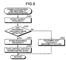
- Fig. 8 is a flowchart for detailed explanation of respective steps until the control unit 16 detects the driving-preparation-time abnormality occurring in the ultrasonic surgical system 10 at step S104.
- the control unit 16 exercises the output setting control over the output control unit 14 if receiving the setting start instruction signal from the switch detection unit 11. If so, the output control unit 14 performs the frequency sweep processing, sets the driving current and the driving voltage, and transmits the detected frequency signal S3 corresponding to the output frequency obtained in this frequency sweep processing and the detected current and voltage signal S4 corresponding to the driving current and the driving voltage thus set to the control unit 16 under control of the control unit 16.
- the control unit 16 detects the output frequency based on the detected frequency signal S3 received from the output control unit 14 (at step S301).
- the control unit 16 detects the output frequency equal to the resonance frequency Fr based on the detected frequency signal S3 received from the output control unit 14.
- the abnormality determination unit 16b constantly monitors the output frequency detected by the detection unit 16 based on the first determination criterion information or the second determination criterion information read from the storage units 2b and 3b in the information read processing. That is, the abnormality determination unit 16b determines whether the output frequency equal to the resonance frequency Fr is within a frequency range set by the frequency upper limit and the frequency lower limit in the first determination criterion information, and whether the output frequency equal to the resonance frequency Fr is within a frequency range set by the frequency upper limit and the frequency lower limit in the second determination criterion information.
- control unit 16 detects the output frequency equal to the resonance frequency Fr and the abnormality determination unit 16b determines that this output frequency is within the frequency range set by the first determination criterion information or the second determination criterion information, then the resonance frequency Fr detected by the output control unit 14 is within this frequency range, and the control unit 16 can detect the resonance frequency within this frequency range based on the detected frequency signal S3 received from the output control unit 14.
- control unit 16 If the control unit 16 can detect the resonance frequency Fr within the frequency range ("Yes" at step S302), the control unit 16 stores the detected resonance frequency in the storage unit 16a as the driving frequency in the output setting information (at step S303). Further, the control unit 16 detects the driving current and the driving voltage set by the output control unit 14 based on the detected current and voltage signal S4 received from the output control unit 14, and stores the detected driving current and driving voltage in the storage unit 16a as the output setting information. Accordingly, the control unit 16 completes making a driving preparation for driving the ultrasonic vibrator 2a to output the ultrasonic vibration having the desired amplitude at the resonance frequency Fr to the probe 3, thus turning into the driving waiting state (at step S304).
- the abnormality determination unit 16 determines that the output frequency equal to the resonance frequency Fr is out of the frequency range, i.e., if the output control unit 14 cannot detect the resonance frequency Fr within the frequency range, the output frequency corresponding to the detected frequency signal S3 is not equal to the resonance frequency Fr within the frequency range. If so, the control unit 16 cannot detect the resonance frequency Fr within the frequency range ("No" at step S302).
- the abnormality determination unit 16b determines that the frequency abnormality occurs in the ultrasonic surgical system 10 (at step S305). Thus, the control unit 16 detects the frequency abnormality occurring in the ultrasonic surgical system 10.
- the abnormality determination unit 16b may calculate an absolute value of the deviation between the output frequency detected by the control unit 16 and the nominal frequency in the first determination criterion information or the second determination criterion information, and determine whether the absolute value of the deviation exceeds the frequency deviation limit in the first determination criterion information or the second determination criterion information. In this alternative, the abnormality determination unit 16b determines that the frequency abnormality occurs in the ultrasonic surgical system 10 if the absolute value of the deviation exceeds the frequency deviation limit in the first determination criterion information or the second determination criterion information.
- Fig. 9 is a flowchart for detailed explanation of respective processing steps until the control unit 16 detects the driving-time abnormality occurring in the ultrasonic surgical system 10 at step S106.
- the control unit 16 exercises the vibrator driving control over the output control unit 14 if receiving the driving start instruction signal from the switch detection unit 11.
- the output control unit 14 controls the ultrasonic vibrator 2a to be driven under control of the control unit 16.
- the ultrasonic vibrator 2a outputs the ultrasonic vibration having the desired amplitude to the probe 3 under driving control of the output control unit 14.
- the output control unit 14 detects the output frequency (i.e., the resonance frequency Fr) of the driving signal S5 for supplying the electric energy to the ultrasonic vibrator 2a, the driving current, and the driving voltage.
- the output control unit 14 transmits the detected frequency signal S3 corresponding to the output frequency and the detected current and voltage signal S4 corresponding to the driving current and the driving voltage to the control unit 16.
- the control unit 16 detects the output frequency, the driving current, and the driving voltage if the ultrasonic vibrator 2a is driven, based on the detected frequency signal S3 and the detected current and voltage signal S4 received from the output control unit 14.
- the information generation unit 16c generates the first accumulated time information corresponding to the accumulated time for which the ultrasonic vibration is output to the probe 3 and the second accumulated time information corresponding to the accumulated time for which the ultrasonic vibrator 2a outputs the ultrasonic vibration.
- the information generation unit 16c also calculates and outputs the capacitance of the ultrasonic vibrator 2a using the driving current and the driving voltage detected by the control unit 16.
- control unit 16 detects the output frequency, driving current, and driving voltage thus obtained, the capacitance calculated and output by the information generation unit 16c, the latest first accumulated time corresponding to the first accumulated time information generated by the information generation unit 16c and the latest second accumulated output time corresponding to the second accumulated time information generated by the information generation unit 16c as driving information on the ultrasonic vibrator 2b (at step S401), and stores the detected driving information in the storage unit 16a.
- the abnormality determination unit 16b determines whether the pieces of driving information stored in the storage unit 16a satisfy respective determination criteria in the first determination criterion information or the second determination criterion information read from the storage units 2b and 3b in the information read processing, using the respective determination criteria (at step S402). For instance, the abnormality determination unit 16b determines whether the output frequency is within a frequency range set by the frequency upper limit and the frequency lower limit in the first determination criterion information or the second determination criterion information. The abnormality determination unit 16b determines whether the driving voltage exceeds the driving voltage upper limit in the first determination criterion information or the second determination criterion information.
- the abnormality determination unit 16b determines whether the driving current is within a current range set by the driving current upper limit and the lower limit driving current in the first determination criterion information or the second determination criterion information. In addition, the abnormality determination unit 16b determines whether the latest first accumulated output time exceeds the first output limit time in the first determination criterion information, and determines whether the latest second accumulated output time exceeds the second output limit time in the second determination criterion information. Further, the abnormality determination unit 16b determines whether the capacitance exceeds the capacitance limit in the second determination criterion information.
- the abnormality determination unit 16b determines that the driving-time abnormality occurs in the ultrasonic surgical system 10 (at step S404). For instance, if the output frequency is out of the frequency range set by the frequency upper limit and the frequency lower limit in the first determination criterion information or the second determination criterion information, the abnormality determination unit 16b determines that the frequency abnormality occurs in the ultrasonic surgical system 10. The control unit 16 detects the frequency abnormality occurring in the ultrasonic surgical system 10.
- the abnormality determination unit 16b determines that the driving voltage abnormality occurs in the ultrasonic surgical system 10. The control unit 16 detects the driving voltage abnormality occurring in the ultrasonic surgical system 10. If the driving current is out of the current range set by the driving current upper limit and the lower limit driving current in the first determination criterion information or the second determination criterion information, the abnormality determination unit 16b determines that the driving current abnormality occurs in the ultrasonic surgical system 10. The control unit 16 detects the driving current abnormality occurring in the ultrasonic surgical system 10.
- the abnormality determination unit 16b can determine that the driving current abnormality resulting from the overload on the handpiece 2 or the probe 3 occurs in the ultrasonic surgical system 10. In addition, if the driving current exceeds the driving current upper limit, the abnormality determination unit 16b can determine that the driving current abnormality resulting from the excessive output of the ultrasonic vibration occurs in the ultrasonic surgical system 10. Furthermore, if the latest first accumulated output time exceeds the first output limit time in the first determination criterion information, the abnormality determination unit 16b determines that the accumulated time abnormality of the probe 3 occurs in the ultrasonic surgical system 10. The control unit 16 detects the accumulated time abnormality of the probe 3 occurring in the ultrasonic surgical system 10.
- the abnormality determination unit 16b determines that the accumulated time abnormality of the handpiece 2 occurs in the ultrasonic surgical system 10. The control unit 16 detects the accumulated time abnormality of the handpiece 2 occurring in the ultrasonic surgical system 10. If the capacitance exceeds the capacitance limit in the second determination criterion information, the abnormality determination unit 16b determines that the handpiece temperature abnormality occurs in the ultrasonic surgical system 10. The control unit 16 detects the handpiece temperature abnormality occurring in the ultrasonic surgical system 10.
- the abnormality determination unit 16b can determine whether the probe temperature abnormality occurs in the ultrasonic surgical system 10 based on a frequency change speed by the time the output frequency changes to the frequency that is out of the frequency range. If so, the information generation unit 16c calculates and outputs this frequency change speed based on a change quantity of the output frequency sequentially detected as the driving information and the output time information received from the time calculation unit 15. If the frequency change speed obtained is lower than a predetermined frequency change speed limit, the abnormality determination unit 16 can determine that the probe temperature abnormality occurs in the ultrasonic surgical system 10. The control unit 16 detects the probe temperature abnormality occurring in the ultrasonic surgical system 10.
- the abnormality determination unit 16b may calculate the absolute value of the deviation between the output frequency of the driving information and the nominal frequency in the first determination criterion information or the second determination criterion information. The abnormality determination unit 16 may also determine whether the absolute value of the deviation exceeds the frequency deviation limit in the first determination criterion information or the second determination criterion information. In this alternative, if the absolute value of the deviation exceeds the frequency deviation limit in the first determination criterion information or the second determination criterion information, the abnormality determination unit 16b can determine that the frequency abnormality occurs in the ultrasonic surgical system 10. The control unit 16 detects the frequency abnormality occurring in the ultrasonic surgical system 10.
- the information generation unit 16c may calculate and output a speed (deviation change speed) at which the deviation between the output frequency and the nominal frequency changes, based on the output frequency and the nominal frequency sequentially detected as the driving information and the output time information received from the time calculation unit 15.
- the abnormality determination unit 16b can determine that the probe temperature abnormality occurs in the ultrasonic surgical system 10.
- the control unit 16 detects the probe temperature abnormality occurring in the ultrasonic surgical system 10.
- the abnormality determination unit 16b determines that the driving-time abnormality does not occur in the ultrasonic surgical system 10. If so, the ultrasonic surgical system 10 is in a normal state in which no driving-time abnormality occurs in the system 10.
- Fig. 10 is a flowchart for detailed explanation of the respective processing steps until the control unit 16 permits the ultrasonic surgical system 10 the driving of which is stopped to be driven again, if the control unit 16 determines whether the abnormality occurs in the ultrasonic surgical system 10 the driving of which is stopped and detects the abnormality occurring in the ultrasonic surgical system 10.
- the switch detection unit 11 detects that the test switch 1c is in an ON-state (at step S501) and transmits the test mode switchover signal to the control unit 16.
- the control unit 16 If receiving the test mode switchover signal from the switch detection unit 11, the control unit 16 performs a mode switchover processing for switching over a driving mode for exercising the output setting control or the vibrator driving control to a test mode for determining whether an abnormality occurs in the ultrasonic surgical system 10 (at step S502). If the control unit 16 is set in the test mode by this mode switchover processing, the control unit 16 releases the prohibition of the reception of the setting start instruction signal, thereby turning into a state in which the control unit 16 can exercise the output setting control.
- the control unit 16 exercises the output setting control over the output control unit 14, and the output control unit 14 sets the driving current and the driving voltage and performs the frequency sweep processing. If so, the output control unit 14 transmits the detected frequency signal S3 corresponding to the output frequency obtained by the frequency sweep processing and the detected current and voltage signal S4 corresponding to the set driving current and driving voltage to the control unit 16.
- the control unit 16 detects the output frequency based on the detected frequency signal S3 received from the output control unit 14, and detects the driving current and the driving voltage based on the detected current and voltage signal S4 received from the output control unit 14.
- the information generation unit 16c calculates and outputs the capacitance of the ultrasonic vibrator 2a using the driving current and the driving voltage detected by the control unit 16. The information generation unit 16c also calculates and outputs the frequency change speed or the deviation change speed using the output frequency detected by the control unit 16.
- the abnormality determination unit 16b performs the abnormality determination processing by performing the same determination processing as that executed at step S402 using the output frequency, the driving current, the driving voltage, the capacitance, and the frequency change speed or the deviation change speed thus obtained. Specifically, the abnormality determination unit 16 determines whether the frequency abnormality, the driving current abnormality, the driving voltage abnormality, the handpiece temperature abnormality, or the probe temperature abnormality occurs in the ultrasonic surgical system 10 (at step S503).
- the control unit 16 preferably exercises the output setting control over the output control unit 14 so that the output control unit 14 performs the frequency sweep processing using the rated current of the handpiece 2 or the probe 3 in the test mode. By doing so, it is possible to promote deteriorating the handpiece 2 or the probe 3 intentionally, and to facilitate determining whether an abnormality occurs in the ultrasonic surgical system 10.
- the control unit 16 further preferably controls the output control unit 14 so as to keep forcedly outputting the ultrasonic vibration from the ultrasonic vibrator 2a to the probe 3 for the predetermined time (e.g., about five seconds), if the output control unit 14 detects the resonance frequency and exercises the PLL control.
- the control unit 16 performs a driving prohibition release processing to thereby release the prohibition of the reception of the instruction by the setting start instruction signal or the driving start instruction signal in the driving mode, and erases the abnormality history information stored in the storage units 2b and 3b (at step S505).
- control unit 16 may transmit the instruction signal for outputting an output sound indicating that this driving prohibition release processing is accomplished to the sound source circuit 17a or the amplification circuit 17b, transmit the instruction signal for outputting an output display indicating that this driving prohibition release processing is accomplished to the display circuit 18, so as to notify the operator that no abnormality occurs in the ultrasonic surgical system 10 and that the driving prohibition release processing is accomplished.
- the control unit 16 determines that the frequency abnormality, the driving current abnormality, the driving voltage abnormality, the handpiece temperature abnormality, or the probe temperature abnormality occurs in the ultrasonic surgical system 10, and the control unit 16 detects the abnormality determined by the abnormality determination unit 16b ("Yes" at step S504), the control unit 16 transmits the instruction signal for outputting the output sound corresponding to the detected abnormality to the sound source circuit 17a or the amplification circuit 17b, or transmits the instruction signal for outputting the output display corresponding to the detected abnormality to the display circuit 18, so as to notify the operator of occurrence of the abnormality to the ultrasonic surgical system 10 (at step S506).
- step S507 Thereafter, if the test mode of the control unit 16 is continued ("No" at step S507), the respective processing steps after step S503 are repeatedly executed. If the test mode of the control unit 16 is switched over to the driving mode ("Yes" at step S507), the operator operates the test switch 1c and inputs the switch-off information on the test switch 1c to the switch detection unit 11. If inputting the switch-off information from the test switch 1c, the switch detection unit 11 detects that the test switch 1c is in an OFF state (at step S508), and transmits the driving mode switchover signal to the control unit 16. If receiving the driving mode switchover signal from the switch detection unit 11, the control unit 16 performs the mode switchover processing for switching over the test mode to the driving mode (at step S509).
- control unit 16 releases the prohibition of the reception of the setting start instruction signal and the driving start instruction signal, thereby turning into a state in which the control unit 16 can exercises the output setting control or the vibrator driving control based on the received instruction signals. Accordingly, the control unit 16 releases the prohibition of the output of the ultrasonic vibration from the ultrasonic vibrator 2a, and permits the ultrasonic vibrator 2a to be driven again.
- the instance of applying the present invention to the scissors type ultrasonic surgical system for incising the treatment target such as the biological tissue has been explained as one example of the ultrasonic surgical system.
- the present invention is not limited to the embodiment.
- the present invention may be applied to a lithotrity type ultrasonic surgical system for fracturing and aspirating a calculus in a body cavity or the like, a hook type ultrasonic surgical system for carrying out peeling, incision, or the like to the biological tissue or the like, an aspiration type ultrasonic surgical system for emulsifying and aspirating the biological tissue or the like, and various other ultrasonic surgical systems such as an ultrasonic scalpel.
- the control unit 16 reads the vibrator output control information and the second determination criterion information stored in the storage unit 2b and the probe output control information and the first determination criterion information stored in the storage unit 3b by performing the information read processing.
- the control unit 16 may read the second determination criterion information stored in the storage unit 2b and the first determination criterion information stored in the storage unit 3b by the information read processing, and may set the output setting information by operating the up switch 1e, the down switch 1f, or the like provided on the controller 1.
- storage units are arranged in the probe for carrying out the desired medical treatment to the treatment target using the ultrasonic vibration and the handpiece that includes the ultrasonic vibrator to which the probe is connected, respectively.
- the storage unit arranged in the probe stores the determination criterion information on abnormalities of the ultrasonic surgical system including those resulting from the probe.
- the storage unit arranged in the handpiece stores the determination criterion information on abnormalities of the ultrasonic surgical system including those resulting from the handpiece. If the ultrasonic surgical system is turned on, the information read processing for reading the determination criterion information from the storage unit arranged in the probe, and for reading the determination criterion information from the storage unit arranged in the handpiece is carried out.
- determination criterion information can be normally read by the information read processing. It is determined whether the connection abnormality occurs in the ultrasonic surgical system. It is also determined whether the combination abnormality occurs in the ultrasonic surgical system based on the result of the comparison between the determination criterion information read from the storage unit of the probe and that read from the storage unit of the handpiece.
- the driving of the ultrasonic vibrator is controlled and the ultrasonic vibration is output from the ultrasonic vibrator to the probe, then it is determined whether the driving-preparation-time abnormality or the driving-time abnormality occurs in the ultrasonic surgical system based on the determination criterion information read from the storage unit of the probe or that read from the storage unit of the handpiece, and based on various pieces of information on driving control over the ultrasonic vibrator such as the output frequency, the driving current, and the driving voltage. If the driving-preparation-time abnormality or the driving-time abnormality of the ultrasonic surgical system is detected, the driving of the ultrasonic vibrator is stopped and the output of the ultrasonic vibration from the ultrasonic vibrator is prohibited.
- the abnormality resulting from the connection state between the ultrasonic vibrator and the probe or that between the handpiece and the controller, and the abnormality resulting from the combination between the probe and the ultrasonic vibrator can be detected before the ultrasonic vibrator outputs the ultrasonic vibration to the probe. If the ultrasonic vibrator outputs the ultrasonic vibration to the probe, then the abnormality occurring in the ultrasonic surgical system can be detected at an early timing and the output of the ultrasonic vibration by the ultrasonic surgical system for which the driving-preparation-time abnormality or the driving-time preparation is detected can be prohibited. The load on the probe or the handpiece can be thereby reduced, and the deterioration of the probe or the handpiece can be thereby suppressed. Thus, the ultrasonic surgical system having enhanced system safety and improved operation efficiency can be realized. By using this ultrasonic surgical system, the operator can carry out the medical treatment to the treatment target efficiently and safely.
- the abnormality history information that is a history of occurrence of the detected driving-preparation-time abnormality or driving-time preparation is stored, as the determination criterion information on the abnormality, in the storage unit of the probe or that of the handpiece. Therefore, the abnormality history information on the driving-preparation-time abnormality or the driving-time preparation can be followed up for each probe or handpiece. Before the ultrasonic vibrator outputs the ultrasonic vibration to the probe, it is possible to detect that the probe or the handpiece having this abnormality history information is used by the ultrasonic surgical system. It is possible to ensure detecting the abnormality resulting from the probe or the abnormality resulting from the handpiece without accelerating the deterioration of the probe or the handpiece.
- the control unit included in the ultrasonic surgical system can switch over between the driving mode, in which the ultrasonic vibrator is controlled to be driven so as to carry out the medical treatment to the treatment target, and the test mode, in which it is determined whether the abnormality resulting from the probe or the handpiece occurs.
- the test mode if the control unit can determine that the abnormality does not occur in the ultrasonic surgical system, then the control unit erases the abnormality history information stored in at least one of the storage unit of the probe and that of the handpiece, and releases the prohibition of the output of the ultrasonic vibration by the driving prohibition processing. Therefore, it is possible to promptly and efficiently drive the ultrasonic vibrator, the driving of which is stopped by the driving prohibition processing, again if the abnormality occurring in the ultrasonic surgical system is eliminated.
- the accumulated output time at which the ultrasonic vibrator outputs the ultrasonic vibration to the probe is calculated for each of the probe and the handpiece.
- the accumulated output time of the probe is stored in the storage unit of the probe as the abnormality determination criterion information.
- the accumulated output time of the handpiece is stored in the storage unit of the handpiece as the abnormality determination criterion information. Therefore, the accumulated output time can be followed up for each probe or each handpiece. Before the ultrasonic vibrator outputs the ultrasonic vibration to the probe, it is possible to detect the probe or the handpiece the accumulated output time of which exceeds the predetermined specified time.
- the ultrasonic vibrator outputs the ultrasonic vibration to the probe, and the accumulated output time of the probe or that of the handpiece exceeds the predetermined specified time, then the driving prohibition processing is performed and the output of the ultrasonic vibration by the ultrasonic surgical system can be thereby prohibited.
- the ultrasonic surgical system capable of ensuring prohibiting the output of the ultrasonic vibration using the probe or the handpiece, the accumulated output time of which exceeds the predetermined specified time, without accelerating the deterioration of the probe or the handpiece, and having further enhanced safety can be realized.
- the abnormality resulting from the deterioration, the damage, or the like of the probe or the handpiece is detected using the determination criterion information stored in the storage unit of the probe or that stored in the storage unit of the handpiece.
- a short-circuit detection unit that detects electric conduction if the jaw is contacted with the probe is provided, and an abnormality resulting from deterioration of the jaw is detected.
- Fig. 11 is a block diagram of basic configuration of an ultrasonic surgical system according to the second embodiment of the present invention.
- a controller 21 in this ultrasonic surgical system 20 is the same as the controller 1 in the ultrasonic surgical system 10 according to the first embodiment except that a short-circuit detection unit 22 that detects the electric conduction between the jaw 4a of the sheath 4 and the probe 3 is provided in the controller 21. Since the other constituent elements according to the second embodiment are the same as those according to the first embodiment, the same constituent elements are denoted by the same reference symbols as those according to the first embodiment.
- the short-circuit detection unit 22 is electrically connected to the probe 3 through the cable 7 and the handpiece 2, and electrically connected to the jaw 4a through the cable 7, the handpiece 2, and the sheath 4. If the probe 3, the jaw 4a, and the short-circuit detection unit 22 form a closed circuit, the short-circuit detection unit 22 functions to detect a continuity resistance of the closed circuit, and to perform a short-circuit detection processing for detecting the electric conduction between the probe 3 and the jaw 4a based on the continuity resistance.
- Fig. 12 is a typical view of an instance in which the jaw 4a is closed relative to the probe 3 by the operation of the grip 4b of the sheath 4 or the like.
- the jaw 4a includes a metal pressing unit 4a-1 made of a metal member such as stainless steel, and a tissue pad 4a-2 made of a resin member such as Teflon (trademark).
- the metal pressing unit 4a-1 includes a shaft 4c, and a link rod 4e operating longitudinally relative to a shaft direction of the sheath 4 while interlocking with the operation of the grip 4b is connected to the shaft 4c.
- the tissue pad 4a-2 is provided on a side of the metal pressing unit 4a-1 on which the unit 4a-1 contacts with the probe 3.
- the metal pressing unit 4a-1 performs an opening and closing operation relative to the probe 3 so as to press the tissue pad 4a-2 against the probe 3 about the shaft 4c by allowing the link rod 4e to operate longitudinally while interlocking with the operation of the grip 4b.
- the jaw 4a can thereby perform the opening and closing operation relative to the probe 3.
- the short-circuit detection unit 22 is electrically connected to the probe 3 through the cable 7 and the handpiece 2, and to the metal pressing unit 4a-1 of the jaw 4a through the cable 7, the handpiece 2, and the link rod 4e of the sheath 4. If the jaw 4a is closed relative to the probe 3, the probe 3, the metal pressing unit 4a-1 of the jaw 4a, and the short-circuit circuit 22 form a closed circuit through the tissue pad 4a-2. If so, the tissue pad 4a-2 functions as an electric resistance of this closed circuit.
- the tissue pad 4a-2 is worn by a friction between the tissue pad 4a-2 and the probe 3 or the treatment target. If the wearing progresses, the metal pressing unit 4a-1 is exposed to the treatment target or the probe 3. Following the progress of this wearing, the tissue pad 4a-2 deteriorates its function as the electric resistance of the closed circuit. Specifically, a continuity resistance of the closed circuit by the tissue pad 4a-2 is reduced if the wearing progresses. If the probe 3 contacts with the metal pressing unit 4a-1 exposed from the tissue pad 4a-2, the continuity resistance is rapidly reduced.
- a jaw 4aa having a conductive buffer layer provided between the metal pressing unit 4a-1 and the tissue pad 4a-2 can be used in place of the jaw 4a.
- Fig. 13 is a typical view of an instance in which the jaw 4aa that is a modification of the jaw 4a is closed relative to the probe 3 by the operation of the grip 4b of the sheath 4 or the like.
- the jaw 4aa has a structure in which the conductive buffer material 4a-3 is provided between the metal pressing unit 4a-1 and the tissue pad 4a-2 of the jaw 4a.
- the conductive buffer material 4a-3 is made of conductive resin such as silicon-based resin or carbon-based resin.
- the conductive buffer material 4a-3 functions as a conductor electrically connected to the metal pressing unit 4a-1, and also functions as a buffer that hampers contact between the probe 3 and the metal pressing unit 4a-1 and that relaxes an impact caused by the contact of the metal pressing unit 4a-1 with the probe 3.
- a conductive resistance of the conductive buffer 4a-3 can be set at a desired resistance by adjusting a content of a conductive material such as carbon contained in the buffer 4a-3.
- the short-circuit unit 22 is electrically connected to the probe 3 similarly to the instance of using the jaw 4a, and electrically connected to the conductive buffer 4a-3 through the cable 7, the handpiece 2, the link rod 4e of the sheath 4, and the metal pressing unit 4a-1 of the jaw 4a. If the jaw 4a is closed relative to the probe 3, the probe 3, the conductive buffer 4a-2 of the jaw 4a, and the short-circuit detection unit 22 form a closed circuit through the tissue pad 4a-2. If so, the tissue pad 4a-2 functions as an electric resistance of the closed circuit.
- the tissue pad 4a-2 is worn by the friction between the tissue pad 4a-2 and the probe 3 or the treatment target. If the wearing progresses, the conductive buffer 4a-3 is exposed to the treatment target or the probe 3. The continuity resistance of the closed circuit by the tissue pad 4a-2 is reduced if the wearing progresses. If the probe 3 contacts with the conductive buffer 4a-3 exposed from the tissue pad 4a-2, the continuity resistance is rapidly reduced.
- the conductive buffer 4a-3 conducts an electric signal to the metal pressing unit 4a-1 or the probe 3, and relaxes an impact caused by the contact with the probe 3.
- the conductive buffer 4a-3 is worn by the friction with the probe 3 if relaxing the impact caused by the contact with the probe. If this wearing progresses to expose the metal pressing unit 4a-1, then the probe 3 contacts with the metal pressing unit 4a-1 and the conductive buffer 4a-3 loses its function as a buffer.
- a thickness of the conductive buffer 4a-3 may be set equal to or larger than a thickness of the resin that is worn by the friction with the probe 3 since the probe 3 contacts with the conductive buffer 4a-3 until the output of the ultrasonic vibration to the probe 3 is prohibited.
- the thickness of the conductive buffer 4a-3 may be, for example, one millimeter. The conductive buffer 4a-3 can thereby ensure hampering the contact between the probe 3 and the metal pressing unit 4a-1, and preventing the jaw 4aa or the probe 3 from being damaged.
- Fig. 14 is a flowchart of respective processing steps at which if the short-circuit detection unit 22 detects the electric conduction between the probe 3 and the jaw 4a, the control unit 16 detects the wearing abnormality and prohibits the output of the ultrasonic vibration to the probe 3. Referring to Fig.
- the switch detection unit 11 detects that the power switch 1a is in an ON-state. Thereafter, the switch detection unit 11 transmits the information read instruction signal to the control unit 16, and transmits an instruction signal (a short-circuit detection instruction signal) for starting a short-circuit detection processing by the short-circuit detection unit 22 to the control unit 16. If receiving the information read instruction signal from the switch detection unit 11, the control unit 16 reads at least the determination criterion information from the storage units 2b and 3b as already explained.
- the control unit 16 reads a continuity resistance limit serving as a criterion as to whether an electric signal is conducted between the probe 3 and the jaw 4a as the determination criterion information read from the storage units 2b and 3b. If receiving the short-circuit detection instruction signal from the switch detection unit 11, then the control unit 16 transmits conduction determination criterion information corresponding to the continuity resistance read from the storage units 2b and 3b to the short-circuit detection unit 22, and controls the short-circuit detection unit 22 to perform the short-circuit detection processing.
- the short-circuit detection unit 22 constantly transmits a feeble current signal to the probe 3 or the jaw 4a, constantly detects the continuity resistance of the closed circuit that conducts the electric signal, and detects the electric continuity between the probe 3 and the jaw 4a based on a result of comparison between the continuity resistance and the continuity determination criterion information received from the control unit 16 under control of the control unit 16 (at step S601). Specifically, the short-circuit detection unit 22 detects the continuity resistance of the closed circuit based on a current and a voltage of the electric signal, and compares the continuity resistance limit corresponding to the conduction determination criterion information with the detected continuity resistance.
- the short-circuit detection unit 22 detects the electric conduction between the probe 3 and the jaw 4a, i.e., a short-circuit between the probe 3 and the jaw 4a resulting from the wearing of the tissue pad 4a-2. If the jaw 4a is closed relative to the probe 3, the control unit 16 may control the short-circuit detection unit 22 to detect the electric continuity between the probe 3 and the jaw 4a.
- the short-circuit detection unit 22 transmits a short-circuit detection signal indicating that the unit 22 detects this short-circuit to the control unit 16. If the control unit 16 receives the short-circuit detection signal from the short-circuit detection unit 22, then the abnormality determination unit 16b determines that the wearing abnormality occurs in the ultrasonic surgical system 20 based on this short-circuit detection signal (at step S603). Thus, the control unit 16 detects the wearing abnormality occurring in the ultrasonic surgical system 20.
- the “wearing abnormality” means herein an abnormality resulting from wearing of the tissue pad 4a-2 by the friction between the tissue pad 4a-2 and the probe 3 or the treatment target. Namely, the wearing abnormality is such that the metal pressing unit 4a-1 of the jaw 4a or the conductive buffer material 4a-3 of the jaw 4aa is exposed, thereby deteriorating efficiency of the medical treatment carried out to the treatment target and causing a damage of the probe 3.
- the control unit 16 prohibits the output of the ultrasonic vibration from the ultrasonic vibrator 2a, controls the output of the output sound or output display corresponding to the detected wearing abnormality, and notifies the operator of occurrence of the wearing abnormality to the ultrasonic surgical system 20 (at step S604). Thereafter, the information generation unit 16c generates the abnormality history information corresponding to the detected wearing abnormality, and the control unit 16 stores the abnormality history information generated by the information generation unit 16c in the storage units 2b and 3b (at step S605). Alternatively, the control unit 16 may perform the abnormality history information storage processing at step S605 either simultaneously with or before the driving prohibition processing at step S604.
- the control unit 16 may omit the abnormality history information storage processing at step S605.
- the information generation unit 16c does not generate the abnormality history information corresponding to the wearing abnormality, and the control unit 16 does not store the abnormality history information corresponding to the wearing abnormality in the storage units 2b and 3b.
- the operator can recognize that the wearing abnormality occurs in the ultrasonic surgical system 20, and replace the sheath 4 including the defective jaw 4a by another one without causing the damage of the probe 3, the malfunction of the handpiece 2, or the like.
- the operator can carry out the abnormality determination processing to the ultrasonic surgical system 20 by the operation of the test switch 1c or the like. If it is determined that no wearing abnormality occurs in the ultrasonic surgical system 20, the control unit 16 can permit the ultrasonic vibrator 2a the driving of which is stopped by the driving prohibition processing performed due to the wearing abnormality to be driven again.
- the short-circuit detection unit 22 detects the continuity resistance of the closed circuit formed by the probe 3, the jaw 4a, and the short-circuit detection unit 22. In addition, the short-circuit detection unit 22 detects the short-circuit between the probe 3 and the jaw 4a based on the result of the comparison between the continuity resistance and the continuity resistance limit serving as the continuity determination criterion.
- the short-circuit detection unit 22 may detect the current of the electric signal conducted to the closed circuit formed by the probe 3, the jaw 4a, and the short-circuit detection unit 22, and may detect the short-circuit between the probe 3 and the jaw 4a based on the result of the comparison between the current and the current limit serving as the continuity determination criterion.
- the short-circuit detection unit 22 is provided in the controller 21 separately from the control unit 16.
- the present invention is not limited to this embodiment.
- the short-circuit detection unit 22 may be provided in the control unit 16.
- the ultrasonic surgical system if the ultrasonic surgical system is turned on, the electric signal is constantly transmitted to the probe or the jaw. If the closed circuit including the probe and the jaw is formed, then the continuity resistance of the closed circuit is detected based on the current and the voltage of the electric signal conducted to this closed circuit, and the short-circuit between the probe and the jaw is detected based on the detected continuity resistance. Therefore, before the ultrasonic vibration is output, the contact between the jaw having the worn tissue pad and the probe can be detected. If the ultrasonic vibration is output, the contact between the jaw having the worn tissue pad and the probe can be detected at an early timing, and the output of the ultrasonic vibration can be prohibited.
- the ultrasonic surgical system capable of reducing the load on the probe or the handpiece, suppressing the deterioration of the probe or the handpiece, replacing the jaw deteriorated by the wearing of the tissue pad or the like with another jaw efficiently, and carrying out the medical treatment to the treatment target efficiently and safely.
- this conductive buffer relaxes the impact caused by the contact with the probe and realizes the electric continuity with the probe. Therefore, the contact between the probe and the metal pressing unit can be hampered, and the wearing of the tissue pad can be detected. It is thereby possible to prevent the damage of the probe during a surgical operation, improve operation efficiency, and further enhance operation safety.
Abstract
Description
- The present invention relates to an ultrasonic surgical system which performs a surgical, medical treatment such as coagulation and incision of a biological tissue, lithotrity, and aspiration by applying an ultrasonic vibration, and an abnormality detection method and an abnormality detection program for the ultrasonic surgical system.
- There has been conventionally developed an ultrasonic surgical system which includes a handpiece having an ultrasonic vibrator incorporated therein and a probe connected to the ultrasonic vibrator, which contacts a probe, to which an ultrasonic vibration is transmitted, with a biological tissue or the like, and which conducts a surgical, medical treatment such as incision, excision, or aspiration to the biological tissue. The ultrasonic vibration output from the ultrasonic vibrator of this ultrasonic surgical system is realized by controlling this ultrasonic vibrator to be driven. Generally, it is desirable that the ultrasonic vibrator is driven at a resonance frequency or a frequency near the resonance frequency (hereinafter, "near-resonance frequency").
- If an overload is imposed on a vibration system in the ultrasonic surgical system due to one of various abnormalities such as a damage of the probe, adhesion of a blood or the like, and a malfunction and the like of the handpiece, the ultrasonic vibrator of this ultrasonic surgical system is difficult to drive at the resonance frequency or the near-resonance frequency. This results in deterioration of a function of the ultrasonic surgical system to ensure performing the medical treatment. If so, the ultrasonic surgical system needs to stop driving the ultrasonic vibrator at an early timing or to alarm an operator so as to prevent recurrence or deterioration of the abnormalities.
- It is an object of the present invention to at least solve the problems in the conventional technology.
- An ultrasonic surgical system according to one aspect of the present invention includes a handpiece including an ultrasonic vibrator, and a first storage unit that stores first determination criterion information being a criterion of whether an abnormality occurs in the ultrasonic surgical system; a probe including a second storage unit that stores second determination criterion information as a criterion of whether an abnormality occurs in the ultrasonic surgical system, connected to the ultrasonic vibrator, and transmitting ultrasonic vibrations output from the ultrasonic vibrator to a treatment target; and a control unit determining whether the abnormality occurs in the ultrasonic surgical system based on the first determination criterion information and the second determination criterion information, stopping driving the ultrasonic vibrator if determining that the abnormality occurs in the ultrasonic surgical system.
- A method of detecting an abnormality of an ultrasonic surgical system which includes (1) a handpiece having an ultrasonic vibrator and (2) a probe connected to the ultrasonic vibrator, according to another aspect of the present invention includes determining whether an abnormality occurs in the ultrasonic surgical system based on first determination criterion information on the handpiece and second determination criterion information on the probe before the ultrasonic vibrator is driven; determining whether a resonance point of the ultrasonic vibrator is detected within a frequency range set by one of the first determination criterion information and the second determination criterion information if the abnormality is not determined before the ultrasonic vibrator is driven; determining that an abnormality occurs in the ultrasonic surgical system if the resonance point is not detected within the frequency range; determining whether an abnormality occurs to the ultrasonic surgical system based on driving information obtained during driving of the ultrasonic vibrator and based on one of the first determination criterion information and the second determination criterion information if the abnormality is not determined based on the resonance point; and stopping driving the ultrasonic vibrator when the abnormality is determined.
- The computer program product according to still another aspect of the present invention realizes the method according to the present invention on a computer.
- The other objects, features, and advantages of the present invention are specifically set forth in or will become apparent from the following detailed description of the invention when read in conjunction with the accompanying drawings.
-
- Fig. 1 is a typical view of schematic configuration of an ultrasonic surgical system according to a first embodiment of the present invention;
- Fig. 2 is a typical view of a connection state among a handpiece, a probe, and a sheath;
- Fig. 3 is a longitudinal sectional, typical view of an arrangement state of a storage unit arranged in the probe;
- Fig. 4 is a block diagram of basic configuration of the ultrasonic surgical system according to the first embodiment of the present invention;
- Fig. 5 is a block diagram of basic configuration of an output control unit;
- Fig. 6 is a flowchart of various processing steps since an abnormality that occurs in the ultrasonic surgical system is detected until a processing for prohibiting the driving of this ultrasonic surgical system is performed;
- Fig. 7 is a flowchart for detailed explanation of the respective processing steps until a before-driving-time abnormality that occurs in the ultrasonic surgical system is detected;
- Fig. 8 is a flowchart for detailed explanation of the respective processing steps until a driving-preparation-time abnormality that occurs in the ultrasonic surgical system is detected;
- Fig. 9 is a flowchart for detailed explanation of the respective processing steps until a driving-time abnormality that occurs in the ultrasonic surgical system is detected;
- Fig. 10 is a flowchart for detailed explanation of the respective processing steps until an abnormality determination processing is performed in a test mode and an ultrasonic vibrator that has been stopped is permitted to be driven again;
- Fig. 11 is a block diagram of basic configuration of an ultrasonic surgical system according to a second embodiment of the present invention;
- Fig. 12 is a typical view of a state in which a jaw is closed relative to a probe;
- Fig. 13 is a typical view of a state in which a jaw is closed relative to a probe according to a modification of the second embodiment; and
- Fig. 14 is a flowchart of respective processing steps of prohibiting output of an ultrasonic vibration to the probe if it is detected that a short-circuit between the probe and the jaw occurs.
-
- Exemplary embodiments of an ultrasonic surgical system, and an abnormality detection method and an abnormality detection program for the ultrasonic surgical system according to the present invention will be explained hereinafter with reference to the accompanying drawings. A scissors type ultrasonic surgical system which incises a treatment target such as a biological tissue will be explained hereinafter as an ultrasonic surgical system according to the present invention.
- Fig. 1 is a typical view of the schematic configuration of the ultrasonic surgical system according to a first embodiment of the present invention. In Fig. 1, the ultrasonic
surgical system 10 includes a controller main unit (hereinafter, "controller") 1, ahandpiece 2, aprobe 3, asheath 4, and afoot switch 5. Thecontroller 1 includes apower switch 1a, aconnector 1b, atest switch 1c, adisplay unit 1d, anup switch 1e, and adown switch 1f. Thehandpiece 2 includes an ultrasonic vibrator (not shown) therein. Theprobe 3 is screwed with this ultrasonic vibrator. Theprobe 3 is inserted into thesheath 4, and thesheath 4 is detachably connected to thehandpiece 2. If so, thesheath 4 covers theprobe 3 for carrying out a medical treatment to a treatment target so as to expose a tip end of theprobe 3 from a tip end of thesheath 4. Thefoot switch 5 includespedals controller 1 through acable 6. Thehandpiece 2 includes acable 7 having aplug 8 provided on one end. An other end of thecable 7 is electrically connected to the ultrasonic vibrator included in thehandpiece 2. If theplug 8 is connected to theconnector 1b in thecontroller 1, thehandpiece 2 is electrically connected to thecontroller 1. - If the
power switch 1a is operated to turn on thecontroller 1, thecontroller 1 acquires output setting information on the ultrasonic vibrator included in thehandpiece 2 based on an instruction input from thepedal foot switch 5, or controls the ultrasonic vibrator to be driven based on the acquired output setting information, and outputs a desired ultrasonic vibration to the ultrasonic vibrator. Thecontroller 1 can adjust the output setting information on the ultrasonic vibrator included in thehandpiece 2 by operating the upswitch 1e or thedown switch 1f. - The ultrasonic vibrator included in the
handpiece 2 outputs the desired ultrasonic vibration to theprobe 3 while being controlled to be driven by thecontroller 1. Theprobe 3, which is made of titanium or a titanium alloy, transmits the ultrasonic vibration output from the ultrasonic vibrator of thehandpiece 2 to the tip end of theprobe 3. - The
sheath 4 includes ajaw 4a, agrip 4b, and ashaft 4c. Thejaw 4a opens and closes the tip end of the probe about theshaft 4c by operating thegrip 4b, and presses the treatment target on the tip end of theprobe 3. If the desired ultrasonic vibration is transmitted to the tip end of theprobe 3, then thejaw 4a performs an opening or closing operation based on the operation of thegrip 4b, presses the treatment target on the tip end of theprobe 3, and transmits the ultrasonic vibration to the treatment target. The medical treatment such as incision to the treatment target is thereby performed. In other words, thejaw 4a acts as a pressing unit that presses the treatment target on the tip end of theprobe 3. - An arrangement state of the
handpiece 2, theprobe 3, and thesheath 4 will next be explained in detail. Fig. 2 is a typical view of the connection state between the ultrasonic vibrator included in thehandpiece 2 and theprobe 3 and between thesheath 4 into which theprobe 3 is inserted and thehandpiece 2. Fig. 2 also depicts a waveform of the ultrasonic vibration transmitted by theprobe 3. - In Fig. 2, the
handpiece 2 includes therein anultrasonic vibrator 2a and astorage unit 2b. Theultrasonic vibrator 2a is screwed with theprobe 3 by ascrewing unit 2c. Theprobe 3 has an opening 3a formed near thescrewing unit 2c, and astorage unit 3b arranged in the opening 3a. Theultrasonic vibrator 2a and thestorage unit 2b are electrically connected to thecable 7. If theprobe 3 is screwed with theultrasonic vibrator 2a, thestorage unit 3b is electrically connected to thecable 7 through a wiring provided at thehandpiece 2. Accordingly, if theplug 8 is connected to theconnector 1b of thecontroller 1 through thecable 7, then theultrasonic vibrator 2a and thestorage unit 2b are electrically connected to thecontroller 1 through thecable 7 and thestorage unit 3b is electrically connected to thecontroller 1 through thehandpiece 2 and thecable 7. If theultrasonic vibrator 2a, which is made of piezoelectric ceramic such as PZT, is electrically connected to thecontroller 1, theultrasonic vibrator 2a is controlled to be driven by thecontroller 1. By controlling theultrasonic vibrator 2a to be driven by thecontroller 1, theultrasonic vibrator 2a can output the desired ultrasonic vibration to theprobe 3 through thescrewing unit 2c. - The
sheath 4, into which theprobe 3 is inserted, is connected to thehandpiece 2. If so, then a desired number ofseal materials 4d are arranged at desired positions of an outer wall of theprobe 3, respectively, and theprobe 3 is detachably supported by thesheath 4 through theseal materials 4d. In this state, if theultrasonic vibrator 2a outputs the ultrasonic vibration to theprobe 3 through the screwingunit 2c, a longitudinal wave (standing wave) corresponding to this ultrasonic vibration occurs in theprobe 3. As shown in Fig. 2, a phase of a waveform of the standing wave occurring in theprobe 3 corresponds to a distance between theprobe 3 near the screwingunit 2c of and the tip end of theprobe 3, i.e., a position of the wave on theprobe 3. The standing wave occurring in theprobe 3 possesses a knot at a position at which theprobe 3 is supported by thesheath 4 through theseal materials 4d and a belly on the tip end of theprobe 3 for performing the medical treatment to the treatment target. Namely, theseal materials 4d are arranged so that this standing wave possesses the belly on the tip end of theprobe 3, whereby theprobe 3 can ensure transmitting the desired ultrasonic vibration to the tip end of theprobe 3. - The number of
seal materials 4d may be set so as to be able to ensure that theprobe 3 is supported by thesheath 4. Desirably, the number ofseal materials 4d is set so that theseal materials 4d are arranged equidistantly. If so setting, phenomena such as a bending and a shake of theprobe 3 resulting from the ultrasonic vibration can be suppressed, thereby making it possible to reduce a load on theprobe 3 and to stably transmit the ultrasonic vibration. O-rings or the like made of various resin such as silicon or rubber can be used as theseal materials 4d. - Fig. 3 is a longitudinal sectional, typical view of an arrangement state of the
storage unit 3b arranged in theopening 3a of theprobe 3. In Fig. 3, thestorage unit 3b is arranged in theopening 3a located on inner peripheries of theseal materials 4d in contact with the outer wall of theprobe 3, and fixed to an inner wall of theprobe 3 through abuffer 3c. Namely, a part of theprobe 3 in which thestorage unit 3b is arranged corresponds to the knot of the standing wave occurring in theprobe 3. - In the
probe 3 to which the ultrasonic vibration is transmitted, a displacement quantity due to the ultrasonic vibration is minimum at the position of the knot of the standing wave that occurs in theprobe 3, and a stress applied by the ultrasonic vibration most concentrates on the position of the knot. Thebuffer 3c is made of an elastic body such as rubber or arbitrary resin such as vinyl resin or urethane resin solely or a combination of the elastic body and the arbitrary resin. Thebuffer 3c fixes thestorage unit 3b to the inner wall of theprobe 3, and buffers concentration of the stress applied by the ultrasonic vibration on thestorage unit 3b. Further, a wiring (not shown) for electrically connecting thestorage unit 3b to thehandpiece 2 is preferably provided on thebuffer 3c. If so providing, it is possible to reduce the stress applied to this wiring and a malfunction such as disconnection can be prevented. If this wiring or thestorage unit 3b is realized by a flexible substrate made of a resin tape or the like, it is possible to further relax the stress applied on this wiring or thestorage unit 3b. Thestorage unit 3b is preferably arranged on a plane including a central axis of a cross section of theprobe 3. If so arranging, the phenomena such as the binding and the shake of theprobe 3 caused by the ultrasonic vibration can be suppressed and the load on theprobe 3 can be reduced. - The basic configuration of the ultrasonic surgical system according to the first embodiment of the present invention will be explained in detail. Fig. 4 is a block diagram of the basic configuration of the ultrasonic
surgical system 10. In Fig. 4, the ultrasonicsurgical system 10 includes thecontroller 1, thefoot switch 5 electrically connected to thecontroller 1 through thecable 6, thehandpiece 2 electrically connected to thecontroller 1 through thecable 7 if theplug 8 is connected to theconnector 1b, and theprobe 3 screwed with theultrasonic vibrator 2a by the screwingunit 2c as explained above. - The
controller 1 includes thepower switch 1a, thetest switch 1c, thedisplay unit 1d, the upswitch 1e, and thedown switch 1f as explained. Thecontroller 1 also includes a switch detection unit 11, an information transmission andreception unit 13, anoutput control unit 14, atime calculation unit 15, acontrol unit 16, asound source circuit 17a, anamplification circuit 17b, aloudspeaker 17c, and adisplay circuit 18. Thepedals power switch 1a, thetest switch 1c, the upswitch 1e, and thedown switch 1f are electrically connected to the switch detection unit 11. Thecontrol unit 16 controls the information transmission andreception unit 13, theoutput control unit 14, thesound source circuit 17a, theamplification circuit 17b, and thedisplay circuit 18. The switch detection unit 11 is electrically connected to thecontrol unit 16. The information transmission andreception unit 13 is electrically connected to thestorage units output control unit 14 is electrically connected to theultrasonic vibrator 2a. It is noted, however, that the electrical connection between theoutput control unit 14 and theultrasonic vibrator 2a is held through a parallel coil (not shown) of theoutput control unit 14 so as to isolate a control potential of the ultrasonicsurgical system 10 from a potential of a patient. Thesound source circuit 17a is electrically connected to theamplification circuit 17b, and theamplification circuit 17b is electrically connected to theloudspeaker 17c. Thedisplay circuit 18 is electrically connected to thedisplay unit 1d. - The switch detection unit 11 is set to constantly read information of switch-on or switch-off input from the
power switch 1a. If receiving the switch-on information from thepower switch 1a, the switch detection unit 11 is set to constantly read information of switch-on or switch-off input from thepedal test switch 1c, the upswitch 1e, or thedown switch 1f. If the switch detection unit 11 inputs the switch-on information from thepower switch 1a, that is, if thecontroller 1 is turned on by the operation of thepower switch 1a, then the switch detection unit 11 detects that thepower switch 1a is in an ON-state, and then transmits an instruction signal (i.e., an information read instruction signal) for reading the output control information and the determination criterion information stored in thestorage units control unit 16. If inputting the switch-on information from thepedal control unit 16. If inputting the switch-off information from thepedal control unit 16. It is assumed that the switch-on information input from thepedal 5a corresponds to an output setting control for detecting the resonance frequency of theultrasonic vibrator 2a to which theprobe 3 is connected, and for setting a driving current and a driving voltage. It is also assumed that the switch-on information input from thepedal 5b corresponds to a driving control over theultrasonic vibrator 2a (a vibrator driving control) based on the detected resonance frequency and the driving current and the driving voltage thus set. If so, then the switch detection unit 11 transmits the instruction signal (setting start instruction signal) for starting the output setting control to thecontrol unit 16 based on the switch-on information input from thepedal 5a, and transmits the instruction signal (setting stop instruction signal) for stopping the output setting control to thecontrol unit 16 based on the switch-off information input from thepedal 5a. Further, the switch detection unit 11 transmits the instruction signal (driving start instruction signal) for starting the vibrator driving control to thecontrol unit 16 based on the switch-on information input from thepedal 5b, and transmits the instruction signal (driving stop instruction signal) for stopping the vibrator driving control to thecontrol unit 16 based on the switch-off information input from thepedal 5b. - If inputting the switch-on information from the
test switch 1c, the switch detection unit 11 transmits an instruction signal (a test mode switchover signal) for switching over a control mode in which thecontrol unit 16 exercises control, to a test mode for testing whether an abnormality occurs in the ultrasonicsurgical system 10 to thecontrol unit 16. If inputting the switch-off information from thetest switch 1c, the switch detection unit 11 transmits an instruction signal (a driving mode switchover signal) for switching over the control mode for thecontrol unit 16 to a driving mode for exercising the output setting control or the vibrator driving control to thecontrol unit 16. If inputting the switch-on information from the upswitch 1e, the switch detection unit 11 transmits an instruction signal (a setting increase instruction signal) for increasing an output set value such as the driving current or the driving voltage by predetermined numeric values to thecontrol unit 16. If inputting the switch-on information from thedown switch 1f, the switch detection unit 11 transmits an instruction signal (a setting decrease instruction signal) for decreasing the output set value such as the driving current or the driving voltage by predetermined numeric values to thecontrol unit 16. If receiving the switch-on information from the upswitch 1e and the switch-on information from thedown switch 1f simultaneously, the switch detection unit 11 transmits an instruction signal (a sound setting start signal) for starting a volume setting or a tone setting of an output sound output from theloudspeaker 17c to thecontrol unit 16. - If detecting that both the
up switch 1e and thedown switch 1f have been in switch ON-states for a predetermined time (e.g., about one second) or more, then the switch detection unit 11 preferably recognizes that the unit 11 simultaneously receives the switch-on information from the upswitch 1e and the switch-on information from thedown switch 1f, and transmits a sound setting instruction signal to thecontrol unit 16. By doing so, the respective operations for changing the output set value and setting the output sound can be clearly distinguished from one another and it is possible to ensure performing the respective operations. - If the switch detection unit 11 transmits the information read instruction signal to the
control unit 16, the information transmission andreception unit 13 reads the output control information and the determination criterion information from thestorage units control unit 16. Specifically, the information transmission andreception unit 13 reads probe output control information and first determination criterion information stored in thestorage unit 3b and vibrator output control information and second determination criterion information stored in thestorage unit 2b. The information transmission andreception unit 13 converts the read probe output control information, vibrator output control information, first determination criterion information, and second determination criterion information into predetermined digital codes, respectively, and transmits the respective pieces of information converted into the predetermined digital codes to thecontrol unit 16. Thus, thecontrol unit 16 accomplishes an information read processing for reading the probe output control information and the first determination criterion information stored in thestorage unit 3b, and the vibrator output control information and the second determination criterion information stored in thestorage unit 2b. Further, if abnormality history information on a history of an abnormality that occurs in the ultrasonicsurgical system 10 is stored in thestorage unit 3b as the first determination criterion information, and stored in thestorage unit 2b as the second determination criterion information, then the information transmission andreception unit 13 reads the abnormality history information from thestorage unit 3b as the first determination criterion information or reads the abnormality history information from thestorage unit 2b as the second determination criterion information under control of thecontrol unit 16. - The output control information includes probe output control information serving as parameters for ultrasonic output characteristics of the
probe 3 and vibrator output control information serving as parameters for ultrasonic characteristics of theultrasonic vibrator 2a. The probe output control information includes, for example, a driving frequency, an amplitude magnification factor, a boosting ratio, and a rated voltage of theprobe 3. The vibrator output control information includes, for example, a driving frequency, a current amplitude ratio, a boosting ratio, and a rated voltage of theultrasonic vibrator 2a. The driving frequency is a frequency parameter corresponding to a reference frequency at which a frequency sweep processing for detecting a resonance frequency is performed. The current amplitude ratio and the amplitude magnification factor are operation parameters for operating and outputting a driving current parameter for setting a driving current at which an ultrasonic vibration having a desired amplitude is output. The boosting ratio is a current control parameter for setting a driving voltage dependent on impedance characteristics of theprobe 3 and theultrasonic vibrator 2a. The rated voltage is a parameter for setting a maximum output voltage of a control signal for controlling driving of theultrasonic vibrator 2a. - The determination criterion information includes the first determination criterion information that is a criterion as to whether an abnormality resulting from the
probe 3 occurs in the ultrasonicsurgical system 10, and the second determination criterion information that is a criterion as to whether an abnormality resulting from thehandpiece 2 occurs in the ultrasonicsurgical system 10. The first determination criterion information includes, for example, a first accumulated output time, a first output control time, a frequency upper limit and a frequency lower limit, a nominal frequency and a frequency deviation limit, a driving voltage upper limit, or a current upper limit and a current lower limit. The second determination criterion information includes, for example, a second accumulated output time, a second output control time, a frequency upper limit and an frequency lower limit, a nominal frequency and a frequency deviation limit, a driving voltage upper limit, a driving current upper limit and a lower limit driving current, or a capacitance limit. The frequency upper limit and the frequency lower limit are values for limiting a sweep range of the driving frequency at which the frequency sweep processing is performed. The nominal frequency corresponds to the resonance frequency of theultrasonic vibrator 2a to which theprobe 3 is connected. The frequency deviation limit is a value for limiting an absolute value of a deviation of the resonance frequency detected by the frequency sweep processing from the nominal frequency. The driving voltage upper limit is a criterion for setting an upper limit of the driving voltage and is a criterion about an abnormality resulting from an overload on theprobe 3 or thehandpiece 2. The driving current upper limit is a criterion for setting an upper limit of the driving current and is a criterion about an abnormality resulting from an excessive output of theprobe 3 or thehandpiece 2. The lower limit driving current is a criterion for setting a lower limit of the driving current and is a criterion about an abnormality resulting from an overload on theprobe 3 or thehandpiece 2. The capacitance limit is a value for limiting a capacitance of thehandpiece 2 dependent on a temperature change of thehandpiece 2. The first accumulated output time is an accumulated time of outputting the ultrasonic vibration to theprobe 3. The first output limit time is a limit to the first accumulated output time. The second accumulated output time is an accumulated time for which theultrasonic vibrator 2a included in thehandpiece 2 outputs the ultrasonic vibration. The second output limit time is a limit to the second accumulated output time. - It is assumed that the information transmission and
reception unit 13 receives the abnormality history information, first accumulated time information corresponding to the first accumulated output time, or second accumulated time information corresponding to the second accumulated output time from the control unit. If so, the information transmission andreception unit 13 stores the received abnormality history information in thestorage unit 3b as the first determination criterion information, stores the received abnormality history information in thestorage unit 2b as the second determination criterion information, stores the received first accumulated time information in thestorage unit 3b as the first determination criterion information, or stores the received second accumulated time information in thestorage unit 2b as the second determination criterion information under control of thecontrol unit 16. Accordingly, thecontrol unit 16 can store the abnormality history information in thestorage unit storage unit 3b, or store the received second accumulated time information in thestorage unit 2b. Thecontrol unit 16 can also update the abnormality history information already stored in thestorage unit storage unit 3b, or update the second accumulated time information already stored in thestorage unit 2b. If thecontrol unit 16 thus updates the information and transmits the abnormality history information indicating that no abnormality occurs in the ultrasonicsurgical system 10 to thestorage unit reception unit 13, thecontrol unit 16 can erase the abnormality history information stored in thestorage unit - Reprogrammable nonvolatile memories such as erasable and programmable read only memory (EPROM) or electrically erasable programmable read only memory (EEPROM) can be employed as the
storage units storage units reception unit 13 are held by serial communication. By using the serial communication, the abnormality history information stored in thestorage unit - The
output control unit 14 is realized by a digital phase synchronized circuit including a direct digital synthesizer (DDS) or the like. Theoutput control unit 14 performs the frequency sweep processing based on a reference frequency signal S1 output from thecontrol unit 16, detects the resonance frequency of theultrasonic vibrator 2a to which theprobe 3 is connected, and exercises PLL control so that theultrasonic vibrator 2a outputs the ultrasonic vibration at the resonance frequency or the near-resonance frequency. In addition, theoutput control unit 14 sets the driving current and the driving voltage based on a current and voltage setting signal S2 output from thecontrol unit 16, and exercises a constant-current control so that a current of a driving signal for supplying an electric energy to theultrasonic vibrator 2a is equal to the desired driving current. Theoutput control unit 14 transmits a driving signal S5 including the set driving current and driving voltage and oscillating at the detected resonance frequency or the near-resonance frequency to theultrasonic vibrator 2a. Theoutput control unit 14 can thereby control the driving of theultrasonic vibrator 2a so as to output the ultrasonic vibration having the desired amplitude at the resonance frequency. - The
output control unit 14 detects an output frequency obtained by the frequency sweep processing, transmits a detected frequency signal S3 corresponding to the output frequency to thecontrol unit 16, detects the driving current and the driving voltage set based on the current and voltage setting signal S2, and transmits a detected current and voltage signal S4 corresponding to the detected driving current and driving voltage to thecontrol unit 16. It is noted that the output frequency is a frequency obtained by raising or lowering the driving frequency so as to detect or follow up the resonance frequency if theoutput control unit 14 performs the frequency sweep processing with the driving frequency used as the resonance frequency. Therefore, if theoutput control unit 14 exercises the PLL control, the output frequency corresponds to the resonance frequency or the near-resonance frequency of theultrasonic vibrator 2a. - The
time calculation unit 15 is realized while including a timer function of calculating an output time at which theultrasonic vibrator 2a outputs the ultrasonic vibration to theprobe 3. Thetime calculation unit 15 calculates the output time at which theultrasonic vibrator 2a outputs the ultrasonic vibration to theprobe 3 if thecontrol unit 16 exercises the output setting control or vibrator driving control to theoutput control unit 14. For instance, if thecontrol unit 16 receives the setting start instruction signal or the driving start instruction signal from the switch detection unit 11, thetime calculation unit 15 starts an output time calculation processing. If thecontrol unit 16 receives the setting stop instruction signal or the driving stop instruction signal from the switch detection unit 11, or stops driving theultrasonic vibrator 2a due to occurrence of the abnormality, thetime calculation unit 15 stops the output time calculation processing. Thereafter, thetime calculation unit 15 transmits output time information corresponding to the output time calculated from the start to the end of this time calculation processing to thecontrol unit 16. In the test mode, thetime calculation unit 15 may calculate the output time at which theultrasonic vibrator 2a outputs the ultrasonic vibration to theprobe 3, and may transmit the calculated output time to thecontrol unit 16 as the output time information. - The
control unit 16 is realized by employing astorage unit 16a including a read only memory (ROM) that stores various pieces of data such as a processing program and a random access memory (RAM) that temporarily stores various pieces or information such as the output setting information and the determination criterion information, a central processing unit (CPU) that executes the processing program stored in the ROM, and the like. Thecontrol unit 16 includes anabnormality determination unit 16b and aninformation generation unit 16c. The CPU included in thecontrol unit 16 enables respective processings to be explained later to be performed by thecontrol unit 16, theabnormality determination unit 16b, and theinformation generation unit 16c, and realizes respective functions of the ultrasonicsurgical system 10 by reading the processing program stored in a ROM included in thestorage unit 16a and then executing the processing program. - If receiving the information read instruction signal from the switch detection unit 11, the
control unit 16 controls the information transmission andreception unit 13 to read the output control information and the determination criterion information from thestorage units storage units reception unit 13, then theinformation generation unit 16c calculates and outputs the driving frequency, the driving current parameter, the boosting ratio, or the like based on the probe output control information and the vibrator output control information read as the output control information, and thecontrol unit 16 stores the respective parameters thus obtained in thestorage unit 16a as the output setting information. Thecontrol unit 16 also stores the read determination criterion information in thestorage unit 16a. - As explained above, the output setting information is information for exercising a driving control so as to output the desired ultrasonic vibration from the
ultrasonic vibrator 2a to theprobe 3. The output setting information includes the driving frequency corresponding to a reference frequency of the frequency sweep processing for detecting the resonance frequency of theultrasonic vibrator 2a to which theprobe 3 is connected, the driving current parameter for setting the driving current for outputting the ultrasonic vibration having the desired amplitude from theultrasonic vibrator 2a, the boosting ratio for setting the driving voltage for exercising the constant-current control to keep the set driving current constant, or the like. - If receiving the setting start instruction signal from the switch detection unit 11, then the
control unit 16 controls theoutput control unit 14 based on the output setting information stored in thestorage unit 16a, and performs the frequency sweep processing for detecting the resonance frequency of theultrasonic vibrator 2a to which theprobe 3 is connected and sets the driving current and the driving voltage. If so, thecontrol unit 16 transmits the reference frequency signal S1 corresponding to the driving frequency stored in thestorage unit 16a and the current and voltage setting signal S2 corresponding to the driving current parameter and the boosting ratio to theoutput control unit 14. Thecontrol unit 16 then receives the detected frequency signal S3 corresponding to the output frequency obtained by the frequency sweep processing performed by theoutput control unit 14, and stores the frequency information corresponding to the received detected frequency signal S3 in thestorage unit 16a as the output setting information. Further, thecontrol unit 16 receives the detected current and voltage signal S4 corresponding to the driving current and the driving voltage set by theoutput control unit 14, and stores the respective information on the driving current and the driving voltage corresponding to the received detected current and voltage signal S4 in thestorage unit 16a as the output setting information. If so, thecontrol unit 16 can use the frequency information and the respective information on the driving current and the driving voltage as the output setting information. If receiving the setting stop instruction signal from the switch detection unit 11, thecontrol unit 16 stops the output setting control. If theoutput control unit 14 exercises the PLL control and sets the driving current and the driving voltage, thecontrol unit 16 can receive a vibrator driving control start instruction by the driving start instruction signal. - Further, if receiving the driving start instruction signal from the switch detection unit 11, the
control unit 16 exercises the vibrator driving control over theoutput control unit 14 based on the output setting information stored in thestorage unit 16a. As a result, theultrasonic vibrator 2a is controlled to be driven to output the ultrasonic vibrator having the desired amplitude to theprobe 3. In this driving control, the ultrasonic vibration output from theultrasonic vibrator 2a is transmitted to theprobe 3 through the screwingunit 2c. The operator can, therefore, carry out the medical treatment such as incision to the treatment target using theprobe 3 to which the ultrasonic vibration having the desired amplitude is transmitted. Thereafter, if receiving the driving stop instruction signal from the switch detection unit 11, thecontrol unit 16 controls theoutput control unit 14 to stop driving theultrasonic vibrator 2a. If thecontrol unit 16 receives the driving stop instruction signal to thereby stop driving theultrasonic vibrator 2a, then theinformation generation unit 16c may generate the output control information corresponding to latest output setting information stored in thestorage unit 16a, and may transmit the generated output control information to thestorage units reception unit 13. By doing so, thecontrol unit 16 can update the output control information stored in thestorage units - If exercising the output setting control or the vibrator driving control to thereby output the ultrasonic vibration from the
ultrasonic vibrator 2a, thecontrol unit 16 can inform the operator that theultrasonic vibrator 2a is outputting the ultrasonic vibration using an output sound or an output display. If so, thecontrol unit 16 may transmit a predetermined display instruction signal to thedisplay circuit 18, and may output the output display indicating that theultrasonic vibrator 2a is outputting the ultrasonic vibration to thedisplay unit 1d. Further, thecontrol unit 16 may transmit a predetermined sound instruction signal to thesound source circuit 17a and output the output sound indicating that theultrasonic vibrator 2a is outputting the ultrasonic vibration from theloudspeaker 17c. At this moment, if receiving the sound setting start signal from the switch detection unit 11, thecontrol unit 16 switches over an output adjustment mode for increasing or decreasing the output set value by predetermined numeric values to a sound adjustment mode for making a volume setting or a tone setting of the output sound. In the sound adjustment mode, thecontrol unit 16 transmits an instruction signal for changing the tone to thesound source circuit 17a or transmits an instruction signal for increasing the volume to theamplification circuit 17b if receiving the setting increase instruction signal. Likewise, if receiving the setting decrease instruction signal, thecontrol unit 16 transmits the instruction signal for changing the tone to thesound source circuit 17a or transmits an instruction signal for reducing the volume to theamplification circuit 17b. As a result, thesound source circuit 17a is set to output a desired tone or theamplification circuit 17b is set to output the output sound having a desired volume. Accordingly, thesound source circuit 17a transmits a sound source signal corresponding to a sound source of the desired tone to theamplification circuit 17b. Theamplification circuit 17b mixes or amplifies the volume-relating instruction signal received from thecontrol unit 16 and the sound source signal received from thesound source circuit 17a, and transmits a signal corresponding to the desired volume and the desired tone to theloudspeaker 17c. Theloudspeaker 17c outputs the output sound of the desired volume and the desired tone based on the signal received from theamplification circuit 17b. Thecontrol unit 16 may control thedisplay circuit 18 so as to display setting information on the tone or the volume of the output sound output from theloudspeaker 17c on thedisplay unit 1d. - Thereafter, if the switch detection unit 11 detects the switch-on information output from the up
switch 1e and the switch-on information output from thedown switch 1f simultaneously again, or if the switch detection unit 11 does not detect the switch-on information output from the upswitch 1e or the switch-on information from thedown switch 1f for a predetermined specified time (e.g., about ten seconds) or more, thecontrol unit 16 switches over the sound adjustment mode to the output adjustment mode. In the output adjustment mode, thecontrol unit 16 increases the output set value and controls thedisplay circuit 18 to display information corresponding to the increased output set value on thedisplay unit 1d if receiving the setting increase instruction signal. Likewise, if receiving the setting decrease instruction signal, thecontrol unit 16 decreases the output set value and controls thedisplay circuit 18 to display information corresponding to the decreased output set value on thedisplay unit 1d. Thedisplay unit 1d may output an output display including characters, symbols, alphanumeric characters, or the like solely or a combination thereof, or may output an output display using a light emitting diode (LED) for indicating the volume. - The
abnormality determination unit 16b determines whether an abnormality (a before-driving-time abnormality) occurs in the ultrasonicsurgical system 10 before theultrasonic vibrator 2a is driven based on a result of the information read processing or the like. In addition, theabnormality determination unit 16b determines whether an abnormality (a driving-preparation-time abnormality) occurs in the ultrasonicsurgical system 10 based on the determination criterion information read from thestorage units reception unit 13 or the like if thecontrol unit 16 exercises the output setting control. Further, theabnormality determination unit 16b determines whether an abnormality (a driving-time abnormality) occurs in the ultrasonicsurgical system 10 based on this determination criterion information or the like if the control unit exercises the vibrator driving control. Examples of the before-driving-time abnormality include a connection abnormality that the connection between theprobe 3 and theultrasonic vibrator 2a or the connection between thehandpiece 2 and theprobe 3 is inappropriate, and a combination abnormality that the combination of thehandpiece 2 and theprobe 3 is inappropriate. Examples of the driving-preparation-time abnormality include a frequency abnormality that occurs due to the overload on the vibration system in the ultrasonicsurgical system 10 resulting from the disconnection of the electric wiring at thehandpiece 2, the damage of theprobe 3, the adhesion of the biological tissue such as the blood to theprobe 3, or the like. Examples of the driving-time abnormality include a driving current abnormality that occurs due to the excessive output of the ultrasonic vibration from theultrasonic vibrator 2a or the overload resulting from the disconnection of the electric wiring at thehandpiece 2, the damage of theprobe 3, or the like, a driving voltage abnormality that the driving voltage is saturated due to the disconnection of the electric wiring at thehandpiece 2, the damage of theprobe 3, or the like, thereby making it difficult to supply the electric energy to theultrasonic vibrator 2a, an accumulated time abnormality that the accumulated output time of theultrasonic vibrator 2a or that of theprobe 3 is equal to or longer than a predetermined limit time, a handpiece temperature abnormality that a temperature of thehandpiece 2 excessively rises, a probe temperature abnormality that a temperature of theprobe 3 excessively rises, and the frequency abnormality. Examples of a combination abnormality detected as the before-driving-time abnormality include an instance in which the abnormality history information on thehandpiece 2 or theprobe 3 is present, and an instance in which the accumulated output time of theultrasonic vibrator 2a or that of theprobe 3 is equal to or longer than the predetermined limit time. - If the
abnormality determination unit 16b determines that the before-driving-time abnormality, the driving-preparation-time abnormality, or the driving-time abnormality occurs in the ultrasonicsurgical system 10, thecontrol unit 16 detects the before-driving-time abnormality, the driving-preparation-time abnormality, or the driving-time abnormality that occurs in the ultrasonicsurgical system 10. If so, thecontrol unit 16 stops driving theultrasonic vibrator 2a, and prohibits reception of the instruction by the setting start instruction signal or the driving start instruction signal received from the switch detection unit 11. Accordingly, thecontrol unit 16 prohibits theultrasonic vibrator 2a from outputting the ultrasonic vibration, transmits the instruction signal for outputting the output sound corresponding to the detected abnormality to thesound source circuit 17a or theamplification circuit 17b, or transmits the instruction signal for outputting the output display corresponding to the detected abnormality to thedisplay circuit 18. Thecontrol unit 16 thus notifies the operator of occurrence of the before-driving-time abnormality, the driving-preparation-time abnormality, or the driving-time abnormality to the ultrasonic surgical system 10 (thecontrol unit 16 performs a driving prohibition processing). - As explained above, the
information generation unit 16c generates and outputs the output setting information such as the driving frequency, the driving current parameter, or the boosting ratio based on the probe output control information and the vibrator output control information read as the output control information. If theabnormality determination unit 16b determines occurrence of the driving-preparation-time abnormality or the driving-time abnormality, theinformation generation unit 16c generates abnormality history information corresponding to occurrence of the driving-preparation-time abnormality or the driving-time abnormality to the ultrasonicsurgical system 10. Thecontrol unit 16 stores the abnormality history information generated by theinformation generation unit 16c in thestorage units reception unit 13. It is noted that thecontrol unit 16 stores the abnormality history information generated by theinformation generation unit 16c according to types of abnormalities. For example, thecontrol unit 16 stores the abnormality history information corresponding to the frequency abnormality, the driving current abnormality, or the driving voltage abnormality in thestorage units control unit 16 stores the abnormality history information corresponding to the accumulation time abnormality or the handpiece temperature abnormality of theultrasonic vibrator 2a in thestorage unit 2b. Thecontrol unit 16 stores the abnormality history information corresponding to the accumulated time abnormality or the probe temperature abnormality of theprobe 3 in thestorage unit 3b. - Further, the
information generation unit 16c calculates and outputs an accumulated time for which the ultrasonic vibration is output to theprobe 3 based on the output time information received from thetime calculation unit 15 and the first accumulated time that is the first determination criterion information read from thestorage unit 3b, and generates the first accumulated time information corresponding to the accumulated time thus obtained. If so, thecontrol unit 16 stores the accumulated time calculated and output by theinformation generation unit 16c in thestorage unit 16a as the latest first accumulated output time. If stopping the driving of theultrasonic vibrator 2a, thecontrol unit 16 transmits the first accumulated time information corresponding to the latest first accumulated output time to thestorage unit 3b through the information transmission andreception unit 13, and stores the first accumulated time information in thestorage unit 3b. Likewise, theinformation generation unit 16c calculates and outputs an accumulated time for which theultrasonic vibrator 2a outputs the ultrasonic vibration based on the output time information received from thetime calculation unit 15 and the second accumulated output time that is the second determination criterion information read from thestorage unit 2b, and generates second accumulated time information corresponding to the accumulated time thus obtained. If so, thecontrol unit 16 stores the accumulated time calculated and output by theinformation generation unit 16c in thestorage unit 16a as the latest second accumulated output time. If stopping the driving of theultrasonic vibrator 2a, thecontrol unit 16 transmits the second accumulated time information corresponding to the latest second accumulated output time to thestorage unit 3b through the information transmission andreception unit 13, and stores the second accumulated time information in thestorage unit 3b. - The configuration of the
output control unit 14 will next be explained in detail. Fig. 5 is a block diagram of the basic configuration of theoutput control unit 14 in the ultrasonicsurgical system 10 according to the first embodiment of the present invention. In Fig. 5, theoutput control unit 14 includes aDDS 14a, anamplification circuit 14b, adetection circuit 14c, and a phasedifference detection circuit 14d. TheDDS 14a is connected to theamplification circuit 14b and the phasedifference detection circuit 14d. Thedetection circuit 14c is connected to theamplification circuit 14b and the phasedifference detection circuit 14d. Thus, theDDS 14a, theamplification circuit 14b, thedetection circuit 14c, and the phasedifference detection circuit 14d form a loop circuit. Further, theDDS 14a and theamplification circuit 14b are connected to thecontrol unit 16, and thedetection circuit 14c is connected to theultrasonic vibrator 2a. - The
DDS 14a oscillates the signal at the driving frequency corresponding to the reference frequency signal S1 received from thecontrol unit 16 and transmits the signal to theamplification circuit 14b right after the ultrasonicsurgical system 10 is actuated. Theamplification circuit 14b sets the driving current using the driving current parameter corresponding to the current and voltage setting signal S2 received from thecontrol unit 16, and sets the driving voltage using the boosting ratio corresponding to the current and voltage setting signal S2. In setting the driving voltage, theamplification circuit 14b selects the boosting ratio so that the rated voltage serving as the output control information is the upper limit of the driving voltage, and makes setting of the driving voltage. Accordingly, theamplification circuit 14b exercises the constant-current control so that the current of the driving signal supplied to theultrasonic vibrator 2a is equal to the driving current which is set using this driving current parameter. Thereafter, theamplification circuit 14 transmits the signal at the driving current and the driving voltage thus set and oscillated at the set frequency by theDDS 14a to thedetection circuit 14c. - The
detection circuit 14c detects a current phase and a voltage phase of the signal received from theamplification circuit 14b, and generates a current phase signal I corresponding to the current phase and a voltage phase signal V corresponding to the voltage phase. Thedetection circuit 14c transmits the current phase signal I and the voltage phase signal V thus generated to the phasedifference detection circuit 14d, and supplies the driving signal S5 to theultrasonic vibrator 2a as the signal received from theamplification circuit 14b. Therefore, thedetection circuit 14c detects the current phase and the voltage phase of the driving signal S5 for driving theultrasonic vibrator 2a. - The phase
difference detection circuit 14d detects a phase difference between the current and the voltage of the driving signal S5 based on the current phase signal I and the voltage phase signal V received from thedetection circuit 14c. The phasedifference detection circuit 14d then generates a frequency control signal for controlling the driving frequency corresponding to the reference frequency signal S1 to be raised or lowered based on the detected phase difference, and transmits the generated frequency control signal to theDDS 14a. If so, theDDS 14a sets the driving frequency corresponding to the reference frequency signal S1 at the reference frequency, raises or lowers the driving frequency according to the frequency control signal received from the phasedifference detection circuit 14d. As a result, theDDS 14a controls the driving frequency so as to set the phase difference detected by the phasedifference detection circuit 14d at zero, oscillates the signal at the driving frequency controlled so that this phase difference is zero, and transmits an output frequency signal to theamplification circuit 14b as the signal oscillated at this driving frequency. Thus, theoutput control unit 14 accomplishes the frequency sweep processing for detecting the resonance frequency of theultrasonic vibrator 2a to which theprobe 3 is connected, and accomplishes the PLL control to control theultrasonic vibrator 2a to output the ultrasonic vibration at the resonance frequency or the near-resonance frequency. Theoutput control unit 14 can thereby transmit the driving signal S5 oscillated at the resonance frequency or the near-resonance frequency thus detected to theultrasonic vibrator 2a, and can control theultrasonic vibrator 2a to be driven to output the ultrasonic vibration having the desired amplitude at the resonance frequency. - Meanwhile, the
DDS 14a detects the output frequency obtained by this frequency sweep processing, and transmits the detection frequency signal S3 corresponding to the output frequency to thecontrol unit 16. Theamplification circuit 14b detects the driving current and the driving voltage which are set based on the current and voltage setting signal S2, and transmits the detected current and voltage signal S4 corresponding to the detected driving current and driving voltage to thecontrol unit 16. During the frequency sweep processing or the PLL control, theDDS 14a constantly detects the output frequency, and constantly transmits the detected frequency signal S3 corresponding to the detected output frequency to thecontrol unit 16. During the constant-current control, theamplification circuit 14b constantly detects the driving current and the driving voltage, and constantly transmits the detected current and voltage signal S4 corresponding to the detected driving current and driving voltage to thecontrol unit 16. As a result, thecontrol unit 16 can detect the latest output frequency, the latest driving current, or the latest driving voltage detected by theoutput control unit 14. - The
output control unit 14 may be realized by using an analog phase synchronized circuit including a phase comparator, a lowpass filter, a voltage control oscillator, and the like. Desirably, however, theoutput control unit 14 is realized by using the digital phase synchronized circuit. This is because if the analog phase synchronized circuit is used, the frequency characteristics of the circuit changes according to the temperature change or the like. - Respective processing steps since the
control unit 16 detects that an abnormality occurs in the ultrasonicsurgical system 10 until the driving prohibition processing is carried out to the ultrasonicsurgical system 10 to which the abnormality occurs will next be explained in detail. Fig. 6 is a flowchart of the respective processing steps since thecontrol unit 16 detects that an abnormality occurs in the ultrasonicsurgical system 10 until the driving prohibition processing is carried out to the ultrasonicsurgical system 10 to which the abnormality occurs. Referring to Fig. 6, if thecontroller 1 is turned on by the operation of thepower switch 1a, then the switch detection unit 11 detects that thepower switch 1a is in a switch-ON-state (power-ON state) (at step S101), and transmits the information read instruction signal to thecontrol unit 16. Thecontrol unit 16 performs the information read processing if receiving the information read instruction signal from the switch detection unit 11. Theabnormality determination unit 16b determines whether the before-driving-time abnormality occurs in the ultrasonicsurgical system 10 based on a result of the information read processing or the determination criterion information read in the information read processing. If theabnormality determination unit 16b determines that the before-driving-time abnormality occurs in the ultrasonicsurgical system 10, thecontrol unit 16 detects the before-driving-time abnormality (at step S102). If theabnormality determination unit 16b determines that the before-driving-time abnormality does not occur in the ultrasonicsurgical system 10, then theinformation generation unit 16c calculates and outputs the driving frequency, the driving current parameter, the boosting ratio, or the like based on the output control information read in the information read processing, and thecontrol unit 16 stores the obtained parameter in thestorage unit 16a as the output setting information. If so, thecontrol unit 16 turns into a state (an instruction reception state) for receiving the output setting control instruction by the setting start instruction signal. - If the
control unit 16 is in the instruction reception state ("Yes" in step S103) and receives the setting start instruction signal from the switch detection unit 11, then thecontrol unit 16 exercises the output setting control over theoutput control unit 14, and performs the frequency sweep processing for detecting the resonance frequency of theultrasonic vibrator 2a to which theprobe 3 is connected. Theabnormality determination unit 16b determines whether the driving-preparation-time abnormality occurs in the ultrasonicsurgical system 10 based on the output frequency detected in the frequency sweep processing and the determination criterion information read in the information read processing. If theabnormality determination unit 16b determines that the driving-preparation-time abnormality occurs in the ultrasonicsurgical system 10, the control unit detects the driving-preparation-time abnormality (at step S104). If theabnormality determination unit 16b determines that the driving-preparation-time abnormality does not occur in the ultrasonicsurgical system 10, then theoutput control unit 14 accomplishes the frequency sweep processing to thereby detect the resonance frequency as explained above. In addition, theoutput control unit 14 exercises the PLL control so as to oscillate the ultrasonic vibration at the resonance frequency or the near-resonance frequency, sets the driving current and the driving voltage, and exercises the constant-current control so as to output the ultrasonic vibration having the desired amplitude. If so, thecontrol unit 16 turns into a state (a driving waiting state) for receiving the vibrator driving control instruction by the driving start instruction signal. - If the
control unit 16 is in the driving waiting state ("Yes" at step S105) and receives the driving start instruction signal from the switch detection unit 11, then thecontrol unit 16 exercises the vibrator driving control over theoutput control unit 14 and drives theultrasonic vibrator 2a to output the ultrasonic vibration having the desired amplitude to theprobe 3. Theabnormality determination unit 16b determines whether the driving-time abnormality occurs in the ultrasonicsurgical system 10 based on the output frequency, the driving current, or the driving voltage detected by theoutput control unit 14 and the determination criterion information read in the information read processing. If theabnormality determination unit 16b determines that the driving-time abnormality occurs in the ultrasonicsurgical system 10, thecontrol unit 16 detects the driving-time abnormality (at step S106). If theabnormality determination unit 16b determines that the driving-time abnormality does not occur in the ultrasonicsurgical system 10, the ultrasonicsurgical system 10 is in a normal state in which no driving-time abnormality occurs in the system 10 ("Yes" at step S107). If so, thecontrol unit 16 exercises the vibrator driving control over theoutput control unit 14 based on the instruction by the driving start instruction signal received from the switch detection unit 11. Theoutput control unit 14 controls theultrasonic vibrator 2a to be driven to output the ultrasonic vibration having the desired amplitude to theprobe 3 under the control of thecontrol unit 16. Thus, the ultrasonic vibration output from theultrasonic vibrator 2a is transmitted to theprobe 3 through the screwingunit 2c. The operator can, therefore, carry out the medical treatment such as incision to the treatment target using theprobe 3 to which the ultrasonic vibration having the desired amplitude is transmitted. Thereafter, if thecontroller 1 is to be turned off ("Yes" at step S108), then the operator operates thepower switch 1a and the switch-off information is input to the switch detection unit 11 from thepower switch 1a. If so, the switch detection unit 11 detects that thepower switch 1a is in a switch-OFF state (power-OFF state), and transmits the driving stop instruction signal to thecontrol unit 16. Thecontrol unit 16 controls theoutput control unit 14 to stop driving theultrasonic vibrator 2a based on the instruction by the driving stop instruction signal received from the switch detection unit 11. If thecontroller 1 is not to be turned off ("No" at step S108), thecontrol unit 16 repeatedly executes the respective steps after step S106. - If the
abnormality determination unit 16b determines that the before-driving-time abnormality occurs in the ultrasonicsurgical system 10 and thecontrol unit 16 is not in the instruction reception state ("No" at step S103), if theabnormality determination unit 16b determines that the driving-preparation-time abnormality occurs in the ultrasonic surgical system and thecontrol unit 16 is not in the driving waiting state ("No" at step 105), or if theabnormality determination unit 16b determines that the driving-time abnormality occurs in the ultrasonicsurgical system 10 and thecontrol unit 16 is not in the normal state ("No" at step S107), then thecontrol unit 16 performs the driving prohibition processing to prohibit theultrasonic vibrator 2a from outputting the ultrasonic vibration, controls the output of the output sound or the output display corresponding to the detected abnormality, and notifies the operator that the before-driving-time abnormality, the driving-preparation-time abnormality, or the driving-time abnormality occurs in the ultrasonic surgical system 10 (at step S110). If the abnormality detected by thecontrol unit 16 is not the before-driving-time abnormality ("No" at step S111), then theinformation generation unit 16c generates the abnormality history information corresponding to the detected abnormality, and thecontrol unit 16 stores the abnormality history information generated by theinformation generation unit 16c in thestorage units control unit 16 may perform the abnormality history information storage processing at step S112 either simultaneously with or before the driving prohibition processing at step S110. If the abnormality detected by thecontrol unit 16 is the before-driving-time abnormality ("Yes" at step S111), theinformation generation unit 16c does not generates the abnormality history information corresponding to the before-driving-time abnormality. Namely, thecontrol unit 16 does not store the abnormality history information corresponding to the before-driving-time abnormality in thestorage units - If the control unit performs the driving prohibition processing at step S110, the operator can recognize occurrence of an abnormality to the ultrasonic
surgical system 10 and carry out a predetermined abnormality processing to the ultrasonicsurgical system 10. Further, thecontrol unit 16 carries out an abnormality determination processing to be explained later to the ultrasonicsurgical system 10 to which the operator carries out the abnormality processing. If checking that no abnormality occurs in the ultrasonicsurgical system 10, thecontrol unit 16 can permit theultrasonic vibrator 2a the driving of which is stopped by the driving prohibition processing to be driven again. - Fig. 7 is a flowchart for detailed explanation of respective processing steps until the
control unit 16 detects the before-driving-time abnormality occurring in the ultrasonicsurgical system 10 at step S102. Referring to Fig. 7, thecontrol unit 16 performs the information read processing if receiving the information read instruction signal from the switch detection unit 11 (at step S201), and reads the output control information and the determination criterion information from thestorage units reception unit 13. If thecontrol unit 16 cannot read the probe output control information or the first determination criterion information from thestorage unit 3b, or cannot read the vibrator output control information or the second determination criterion information from thestorage unit 2b, and thecontrol unit 16 cannot normally complete the information read processing at step S201 ("No" at step S202), then theabnormality determination unit 16b determines that the connection abnormality occurs in the ultrasonic surgical system 10 (at step S203) and thecontrol unit 16 detects the connection abnormality occurring in the ultrasonicsurgical system 10. If so, thecontrol unit 16 performs a connection abnormality processing. Namely, thecontrol unit 16 transmits the instruction signal for outputting the output sound corresponding to occurrence of the connection abnormality to thesound source circuit 17a or theamplification circuit 17b and transmits this output sound from theloudspeaker 17c, or transmits the instruction signal for outputting the output display corresponding to occurrence of the connection abnormality to thedisplay circuit 18, and outputs this output display to thedisplay unit 1d. Thus, thecontrol unit 16 notifies the operator of occurrence of the connection abnormality to the ultrasonic surgical system 10 (at step S204). Thecontrol unit 16 then repeatedly executes the respective steps after step S201. - If the
control unit 16 can read the probe output control information and the first determination criterion information from thestorage unit 3b and the vibrator output control information and the second determination criterion information from thestorage unit 2b, and can normally complete the information read processing at step S201 ("Yes" at step S202), then theabnormality determination unit 16b determines whether the combination of thehandpiece 2 and theprobe 3 is appropriate based on a result of comparison between the nominal frequency or the like in the first determination criterion information and the nominal frequency or the like in the second determination criterion information (at step S205). For example, if the nominal frequency in the first determination criterion information differs from that in the second determination criterion information, if the first accumulated output time is equal to or longer than the first output limit time, if the second accumulated output time is equal to or longer than the second output limit time, or the first determination criterion information or the second determination criterion information includes the abnormality history information, then theabnormality determination unit 16b determines that the combination of thehandpiece 2 and theprobe 3 is inappropriate ("No" at step S206), and determines that the combination abnormality occurs in the ultrasonic surgical system 10 (at step S208). If so, thecontrol unit 16 detects the combination abnormality occurring in the ultrasonicsurgical system 10. - Alternatively, the
abnormality determination unit 16b may determine whether the combination of thehandpiece 2 and theprobe 3 is appropriate based on a result of comparison between the vibrator output control information read from thestorage unit 2b and the probe output control information read from thestorage unit 3b. In this alternative, the vibrator output control information and the probe output control information are used as the determination criterion information for determining whether the combination abnormality occurs in the ultrasonicsurgical system 10. For instance, if the driving frequency of the vibrator output control information differs from that of the probe output control information, theabnormality determination unit 16b determines that the combination abnormality occurs in the ultrasonicsurgical system 10. - If the
abnormality determination unit 16b executes step S205 and determines that the combination of thehandpiece 2 and theprobe 3 is appropriate ("Yes" at step S206), thecontrol unit 16 turns into the instruction reception state (at step S207). If so, the ultrasonicsurgical system 10 is in a normal state in which no connection abnormality and no combination abnormality occur in thesystem 10. - Fig. 8 is a flowchart for detailed explanation of respective steps until the
control unit 16 detects the driving-preparation-time abnormality occurring in the ultrasonicsurgical system 10 at step S104. Referring to Fig. 8, thecontrol unit 16 exercises the output setting control over theoutput control unit 14 if receiving the setting start instruction signal from the switch detection unit 11. If so, theoutput control unit 14 performs the frequency sweep processing, sets the driving current and the driving voltage, and transmits the detected frequency signal S3 corresponding to the output frequency obtained in this frequency sweep processing and the detected current and voltage signal S4 corresponding to the driving current and the driving voltage thus set to thecontrol unit 16 under control of thecontrol unit 16. Thecontrol unit 16 detects the output frequency based on the detected frequency signal S3 received from the output control unit 14 (at step S301). It is noted, however, that if theoutput control unit 14 detects a resonance frequency Fr of theultrasonic vibrator 2a, to which theprobe 3 is connected, in the frequency sweep processing, then thecontrol unit 16 detects the output frequency equal to the resonance frequency Fr based on the detected frequency signal S3 received from theoutput control unit 14. - The
abnormality determination unit 16b constantly monitors the output frequency detected by thedetection unit 16 based on the first determination criterion information or the second determination criterion information read from thestorage units abnormality determination unit 16b determines whether the output frequency equal to the resonance frequency Fr is within a frequency range set by the frequency upper limit and the frequency lower limit in the first determination criterion information, and whether the output frequency equal to the resonance frequency Fr is within a frequency range set by the frequency upper limit and the frequency lower limit in the second determination criterion information. If thecontrol unit 16 detects the output frequency equal to the resonance frequency Fr and theabnormality determination unit 16b determines that this output frequency is within the frequency range set by the first determination criterion information or the second determination criterion information, then the resonance frequency Fr detected by theoutput control unit 14 is within this frequency range, and thecontrol unit 16 can detect the resonance frequency within this frequency range based on the detected frequency signal S3 received from theoutput control unit 14. - If the
control unit 16 can detect the resonance frequency Fr within the frequency range ("Yes" at step S302), thecontrol unit 16 stores the detected resonance frequency in thestorage unit 16a as the driving frequency in the output setting information (at step S303). Further, thecontrol unit 16 detects the driving current and the driving voltage set by theoutput control unit 14 based on the detected current and voltage signal S4 received from theoutput control unit 14, and stores the detected driving current and driving voltage in thestorage unit 16a as the output setting information. Accordingly, thecontrol unit 16 completes making a driving preparation for driving theultrasonic vibrator 2a to output the ultrasonic vibration having the desired amplitude at the resonance frequency Fr to theprobe 3, thus turning into the driving waiting state (at step S304). - If the
abnormality determination unit 16 determines that the output frequency equal to the resonance frequency Fr is out of the frequency range, i.e., if theoutput control unit 14 cannot detect the resonance frequency Fr within the frequency range, the output frequency corresponding to the detected frequency signal S3 is not equal to the resonance frequency Fr within the frequency range. If so, thecontrol unit 16 cannot detect the resonance frequency Fr within the frequency range ("No" at step S302). Theabnormality determination unit 16b determines that the frequency abnormality occurs in the ultrasonic surgical system 10 (at step S305). Thus, thecontrol unit 16 detects the frequency abnormality occurring in the ultrasonicsurgical system 10. - Alternatively, the
abnormality determination unit 16b may calculate an absolute value of the deviation between the output frequency detected by thecontrol unit 16 and the nominal frequency in the first determination criterion information or the second determination criterion information, and determine whether the absolute value of the deviation exceeds the frequency deviation limit in the first determination criterion information or the second determination criterion information. In this alternative, theabnormality determination unit 16b determines that the frequency abnormality occurs in the ultrasonicsurgical system 10 if the absolute value of the deviation exceeds the frequency deviation limit in the first determination criterion information or the second determination criterion information. - Fig. 9 is a flowchart for detailed explanation of respective processing steps until the
control unit 16 detects the driving-time abnormality occurring in the ultrasonicsurgical system 10 at step S106. Referring to Fig. 9, thecontrol unit 16 exercises the vibrator driving control over theoutput control unit 14 if receiving the driving start instruction signal from the switch detection unit 11. In the vibrator driving control, theoutput control unit 14 controls theultrasonic vibrator 2a to be driven under control of thecontrol unit 16. Theultrasonic vibrator 2a outputs the ultrasonic vibration having the desired amplitude to theprobe 3 under driving control of theoutput control unit 14. In addition, theoutput control unit 14 detects the output frequency (i.e., the resonance frequency Fr) of the driving signal S5 for supplying the electric energy to theultrasonic vibrator 2a, the driving current, and the driving voltage. Theoutput control unit 14 then transmits the detected frequency signal S3 corresponding to the output frequency and the detected current and voltage signal S4 corresponding to the driving current and the driving voltage to thecontrol unit 16. Thecontrol unit 16 detects the output frequency, the driving current, and the driving voltage if theultrasonic vibrator 2a is driven, based on the detected frequency signal S3 and the detected current and voltage signal S4 received from theoutput control unit 14. Theinformation generation unit 16c generates the first accumulated time information corresponding to the accumulated time for which the ultrasonic vibration is output to theprobe 3 and the second accumulated time information corresponding to the accumulated time for which theultrasonic vibrator 2a outputs the ultrasonic vibration. Theinformation generation unit 16c also calculates and outputs the capacitance of theultrasonic vibrator 2a using the driving current and the driving voltage detected by thecontrol unit 16. If so, thecontrol unit 16 detects the output frequency, driving current, and driving voltage thus obtained, the capacitance calculated and output by theinformation generation unit 16c, the latest first accumulated time corresponding to the first accumulated time information generated by theinformation generation unit 16c and the latest second accumulated output time corresponding to the second accumulated time information generated by theinformation generation unit 16c as driving information on theultrasonic vibrator 2b (at step S401), and stores the detected driving information in thestorage unit 16a. - Thereafter, the
abnormality determination unit 16b determines whether the pieces of driving information stored in thestorage unit 16a satisfy respective determination criteria in the first determination criterion information or the second determination criterion information read from thestorage units abnormality determination unit 16b determines whether the output frequency is within a frequency range set by the frequency upper limit and the frequency lower limit in the first determination criterion information or the second determination criterion information. Theabnormality determination unit 16b determines whether the driving voltage exceeds the driving voltage upper limit in the first determination criterion information or the second determination criterion information. Theabnormality determination unit 16b determines whether the driving current is within a current range set by the driving current upper limit and the lower limit driving current in the first determination criterion information or the second determination criterion information. In addition, theabnormality determination unit 16b determines whether the latest first accumulated output time exceeds the first output limit time in the first determination criterion information, and determines whether the latest second accumulated output time exceeds the second output limit time in the second determination criterion information. Further, theabnormality determination unit 16b determines whether the capacitance exceeds the capacitance limit in the second determination criterion information. - If the pieces of driving information do not satisfy the respective determination criteria for the driving information as a result of step S402 ("No" at step S403), the
abnormality determination unit 16b determines that the driving-time abnormality occurs in the ultrasonic surgical system 10 (at step S404). For instance, if the output frequency is out of the frequency range set by the frequency upper limit and the frequency lower limit in the first determination criterion information or the second determination criterion information, theabnormality determination unit 16b determines that the frequency abnormality occurs in the ultrasonicsurgical system 10. Thecontrol unit 16 detects the frequency abnormality occurring in the ultrasonicsurgical system 10. If the driving voltage exceeds the driving voltage upper limit in the first determination criterion information or the second determination criterion information, theabnormality determination unit 16b determines that the driving voltage abnormality occurs in the ultrasonicsurgical system 10. Thecontrol unit 16 detects the driving voltage abnormality occurring in the ultrasonicsurgical system 10. If the driving current is out of the current range set by the driving current upper limit and the lower limit driving current in the first determination criterion information or the second determination criterion information, theabnormality determination unit 16b determines that the driving current abnormality occurs in the ultrasonicsurgical system 10. Thecontrol unit 16 detects the driving current abnormality occurring in the ultrasonicsurgical system 10. If the driving current is lower than the driving current upper limit, in particular, theabnormality determination unit 16b can determine that the driving current abnormality resulting from the overload on thehandpiece 2 or theprobe 3 occurs in the ultrasonicsurgical system 10. In addition, if the driving current exceeds the driving current upper limit, theabnormality determination unit 16b can determine that the driving current abnormality resulting from the excessive output of the ultrasonic vibration occurs in the ultrasonicsurgical system 10. Furthermore, if the latest first accumulated output time exceeds the first output limit time in the first determination criterion information, theabnormality determination unit 16b determines that the accumulated time abnormality of theprobe 3 occurs in the ultrasonicsurgical system 10. Thecontrol unit 16 detects the accumulated time abnormality of theprobe 3 occurring in the ultrasonicsurgical system 10. If the latest second accumulated output time exceeds the second output limit time in the second determination criterion information, theabnormality determination unit 16b determines that the accumulated time abnormality of thehandpiece 2 occurs in the ultrasonicsurgical system 10. Thecontrol unit 16 detects the accumulated time abnormality of thehandpiece 2 occurring in the ultrasonicsurgical system 10. If the capacitance exceeds the capacitance limit in the second determination criterion information, theabnormality determination unit 16b determines that the handpiece temperature abnormality occurs in the ultrasonicsurgical system 10. Thecontrol unit 16 detects the handpiece temperature abnormality occurring in the ultrasonicsurgical system 10. - The
abnormality determination unit 16b can determine whether the probe temperature abnormality occurs in the ultrasonicsurgical system 10 based on a frequency change speed by the time the output frequency changes to the frequency that is out of the frequency range. If so, theinformation generation unit 16c calculates and outputs this frequency change speed based on a change quantity of the output frequency sequentially detected as the driving information and the output time information received from thetime calculation unit 15. If the frequency change speed obtained is lower than a predetermined frequency change speed limit, theabnormality determination unit 16 can determine that the probe temperature abnormality occurs in the ultrasonicsurgical system 10. Thecontrol unit 16 detects the probe temperature abnormality occurring in the ultrasonicsurgical system 10. - Alternatively, the
abnormality determination unit 16b may calculate the absolute value of the deviation between the output frequency of the driving information and the nominal frequency in the first determination criterion information or the second determination criterion information. Theabnormality determination unit 16 may also determine whether the absolute value of the deviation exceeds the frequency deviation limit in the first determination criterion information or the second determination criterion information. In this alternative, if the absolute value of the deviation exceeds the frequency deviation limit in the first determination criterion information or the second determination criterion information, theabnormality determination unit 16b can determine that the frequency abnormality occurs in the ultrasonicsurgical system 10. Thecontrol unit 16 detects the frequency abnormality occurring in the ultrasonicsurgical system 10. Further, theinformation generation unit 16c may calculate and output a speed (deviation change speed) at which the deviation between the output frequency and the nominal frequency changes, based on the output frequency and the nominal frequency sequentially detected as the driving information and the output time information received from thetime calculation unit 15. In this alternative, if the deviation change speed thus obtained is lower than a predetermined deviation change speed limit, theabnormality determination unit 16b can determine that the probe temperature abnormality occurs in the ultrasonicsurgical system 10. Thecontrol unit 16 detects the probe temperature abnormality occurring in the ultrasonicsurgical system 10. - If the pieces of the driving information satisfy the respective determination criteria as a result of step S402 ("No" at step S403), the
abnormality determination unit 16b determines that the driving-time abnormality does not occur in the ultrasonicsurgical system 10. If so, the ultrasonicsurgical system 10 is in a normal state in which no driving-time abnormality occurs in thesystem 10. - Respective processing steps until the
control unit 16 permits the ultrasonicsurgical system 10 the driving of which is stopped by the driving prohibition processing to be driven again will be explained in detail. Fig. 10 is a flowchart for detailed explanation of the respective processing steps until thecontrol unit 16 permits the ultrasonicsurgical system 10 the driving of which is stopped to be driven again, if thecontrol unit 16 determines whether the abnormality occurs in the ultrasonicsurgical system 10 the driving of which is stopped and detects the abnormality occurring in the ultrasonicsurgical system 10. Referring to Fig. 10, if inputting the switch-on information from thetest switch 1c, the switch detection unit 11 detects that thetest switch 1c is in an ON-state (at step S501) and transmits the test mode switchover signal to thecontrol unit 16. If receiving the test mode switchover signal from the switch detection unit 11, thecontrol unit 16 performs a mode switchover processing for switching over a driving mode for exercising the output setting control or the vibrator driving control to a test mode for determining whether an abnormality occurs in the ultrasonic surgical system 10 (at step S502). If thecontrol unit 16 is set in the test mode by this mode switchover processing, thecontrol unit 16 releases the prohibition of the reception of the setting start instruction signal, thereby turning into a state in which thecontrol unit 16 can exercise the output setting control. - Specifically, if receiving the setting start signal from the switch detection unit 11, then the
control unit 16 exercises the output setting control over theoutput control unit 14, and theoutput control unit 14 sets the driving current and the driving voltage and performs the frequency sweep processing. If so, theoutput control unit 14 transmits the detected frequency signal S3 corresponding to the output frequency obtained by the frequency sweep processing and the detected current and voltage signal S4 corresponding to the set driving current and driving voltage to thecontrol unit 16. Thecontrol unit 16 detects the output frequency based on the detected frequency signal S3 received from theoutput control unit 14, and detects the driving current and the driving voltage based on the detected current and voltage signal S4 received from theoutput control unit 14. Theinformation generation unit 16c calculates and outputs the capacitance of theultrasonic vibrator 2a using the driving current and the driving voltage detected by thecontrol unit 16. Theinformation generation unit 16c also calculates and outputs the frequency change speed or the deviation change speed using the output frequency detected by thecontrol unit 16. - The
abnormality determination unit 16b performs the abnormality determination processing by performing the same determination processing as that executed at step S402 using the output frequency, the driving current, the driving voltage, the capacitance, and the frequency change speed or the deviation change speed thus obtained. Specifically, theabnormality determination unit 16 determines whether the frequency abnormality, the driving current abnormality, the driving voltage abnormality, the handpiece temperature abnormality, or the probe temperature abnormality occurs in the ultrasonic surgical system 10 (at step S503). - The
control unit 16 preferably exercises the output setting control over theoutput control unit 14 so that theoutput control unit 14 performs the frequency sweep processing using the rated current of thehandpiece 2 or theprobe 3 in the test mode. By doing so, it is possible to promote deteriorating thehandpiece 2 or theprobe 3 intentionally, and to facilitate determining whether an abnormality occurs in the ultrasonicsurgical system 10. Thecontrol unit 16 further preferably controls theoutput control unit 14 so as to keep forcedly outputting the ultrasonic vibration from theultrasonic vibrator 2a to theprobe 3 for the predetermined time (e.g., about five seconds), if theoutput control unit 14 detects the resonance frequency and exercises the PLL control. This is based on the fact that an occurrence rate of mechanical destruction caused by the stress decreases exponentially with the passage of time of applying the stress. In addition, it is thereby possible to improve a reliability of the ultrasonicsurgical system 10 for which it is determined in the abnormality determination processing at step S503 that no abnormality occurs in thesystem 10. - If the
abnormality determination unit 16b determines that no frequency abnormality, no driving current abnormality, no driving voltage abnormality, no handpiece temperature abnormality, and no probe temperature abnormality occur in the ultrasonic surgical system 10 ("No" at step S504), then thecontrol unit 16 performs a driving prohibition release processing to thereby release the prohibition of the reception of the instruction by the setting start instruction signal or the driving start instruction signal in the driving mode, and erases the abnormality history information stored in thestorage units control unit 16 may transmit the instruction signal for outputting an output sound indicating that this driving prohibition release processing is accomplished to thesound source circuit 17a or theamplification circuit 17b, transmit the instruction signal for outputting an output display indicating that this driving prohibition release processing is accomplished to thedisplay circuit 18, so as to notify the operator that no abnormality occurs in the ultrasonicsurgical system 10 and that the driving prohibition release processing is accomplished. - If the
abnormality determination unit 16 determines that the frequency abnormality, the driving current abnormality, the driving voltage abnormality, the handpiece temperature abnormality, or the probe temperature abnormality occurs in the ultrasonicsurgical system 10, and thecontrol unit 16 detects the abnormality determined by theabnormality determination unit 16b ("Yes" at step S504), thecontrol unit 16 transmits the instruction signal for outputting the output sound corresponding to the detected abnormality to thesound source circuit 17a or theamplification circuit 17b, or transmits the instruction signal for outputting the output display corresponding to the detected abnormality to thedisplay circuit 18, so as to notify the operator of occurrence of the abnormality to the ultrasonic surgical system 10 (at step S506). - Thereafter, if the test mode of the
control unit 16 is continued ("No" at step S507), the respective processing steps after step S503 are repeatedly executed. If the test mode of thecontrol unit 16 is switched over to the driving mode ("Yes" at step S507), the operator operates thetest switch 1c and inputs the switch-off information on thetest switch 1c to the switch detection unit 11. If inputting the switch-off information from thetest switch 1c, the switch detection unit 11 detects that thetest switch 1c is in an OFF state (at step S508), and transmits the driving mode switchover signal to thecontrol unit 16. If receiving the driving mode switchover signal from the switch detection unit 11, thecontrol unit 16 performs the mode switchover processing for switching over the test mode to the driving mode (at step S509). If performing the driving prohibition release processing, thecontrol unit 16 releases the prohibition of the reception of the setting start instruction signal and the driving start instruction signal, thereby turning into a state in which thecontrol unit 16 can exercises the output setting control or the vibrator driving control based on the received instruction signals. Accordingly, thecontrol unit 16 releases the prohibition of the output of the ultrasonic vibration from theultrasonic vibrator 2a, and permits theultrasonic vibrator 2a to be driven again. - According to the first embodiment, the instance of applying the present invention to the scissors type ultrasonic surgical system for incising the treatment target such as the biological tissue has been explained as one example of the ultrasonic surgical system. However, the present invention is not limited to the embodiment. The present invention may be applied to a lithotrity type ultrasonic surgical system for fracturing and aspirating a calculus in a body cavity or the like, a hook type ultrasonic surgical system for carrying out peeling, incision, or the like to the biological tissue or the like, an aspiration type ultrasonic surgical system for emulsifying and aspirating the biological tissue or the like, and various other ultrasonic surgical systems such as an ultrasonic scalpel.
- According to the first embodiment, the
control unit 16 reads the vibrator output control information and the second determination criterion information stored in thestorage unit 2b and the probe output control information and the first determination criterion information stored in thestorage unit 3b by performing the information read processing. However, the present invention is not limited to the embodiment. Thecontrol unit 16 may read the second determination criterion information stored in thestorage unit 2b and the first determination criterion information stored in thestorage unit 3b by the information read processing, and may set the output setting information by operating theup switch 1e, thedown switch 1f, or the like provided on thecontroller 1. - As explained so far, according to the first embodiment, storage units are arranged in the probe for carrying out the desired medical treatment to the treatment target using the ultrasonic vibration and the handpiece that includes the ultrasonic vibrator to which the probe is connected, respectively. The storage unit arranged in the probe stores the determination criterion information on abnormalities of the ultrasonic surgical system including those resulting from the probe. The storage unit arranged in the handpiece stores the determination criterion information on abnormalities of the ultrasonic surgical system including those resulting from the handpiece. If the ultrasonic surgical system is turned on, the information read processing for reading the determination criterion information from the storage unit arranged in the probe, and for reading the determination criterion information from the storage unit arranged in the handpiece is carried out. It is determined whether the determination criterion information can be normally read by the information read processing. It is determined whether the connection abnormality occurs in the ultrasonic surgical system. It is also determined whether the combination abnormality occurs in the ultrasonic surgical system based on the result of the comparison between the determination criterion information read from the storage unit of the probe and that read from the storage unit of the handpiece. In addition, if the driving of the ultrasonic vibrator is controlled and the ultrasonic vibration is output from the ultrasonic vibrator to the probe, then it is determined whether the driving-preparation-time abnormality or the driving-time abnormality occurs in the ultrasonic surgical system based on the determination criterion information read from the storage unit of the probe or that read from the storage unit of the handpiece, and based on various pieces of information on driving control over the ultrasonic vibrator such as the output frequency, the driving current, and the driving voltage. If the driving-preparation-time abnormality or the driving-time abnormality of the ultrasonic surgical system is detected, the driving of the ultrasonic vibrator is stopped and the output of the ultrasonic vibration from the ultrasonic vibrator is prohibited. Therefore, the abnormality resulting from the connection state between the ultrasonic vibrator and the probe or that between the handpiece and the controller, and the abnormality resulting from the combination between the probe and the ultrasonic vibrator can be detected before the ultrasonic vibrator outputs the ultrasonic vibration to the probe. If the ultrasonic vibrator outputs the ultrasonic vibration to the probe, then the abnormality occurring in the ultrasonic surgical system can be detected at an early timing and the output of the ultrasonic vibration by the ultrasonic surgical system for which the driving-preparation-time abnormality or the driving-time preparation is detected can be prohibited. The load on the probe or the handpiece can be thereby reduced, and the deterioration of the probe or the handpiece can be thereby suppressed. Thus, the ultrasonic surgical system having enhanced system safety and improved operation efficiency can be realized. By using this ultrasonic surgical system, the operator can carry out the medical treatment to the treatment target efficiently and safely.
- Further, according to the first embodiment, if the driving-preparation-time abnormality or the driving-time preparation occurring in the ultrasonic surgical system is detected, the abnormality history information that is a history of occurrence of the detected driving-preparation-time abnormality or driving-time preparation is stored, as the determination criterion information on the abnormality, in the storage unit of the probe or that of the handpiece. Therefore, the abnormality history information on the driving-preparation-time abnormality or the driving-time preparation can be followed up for each probe or handpiece. Before the ultrasonic vibrator outputs the ultrasonic vibration to the probe, it is possible to detect that the probe or the handpiece having this abnormality history information is used by the ultrasonic surgical system. It is possible to ensure detecting the abnormality resulting from the probe or the abnormality resulting from the handpiece without accelerating the deterioration of the probe or the handpiece.
- Furthermore, according to the first embodiment, the control unit included in the ultrasonic surgical system can switch over between the driving mode, in which the ultrasonic vibrator is controlled to be driven so as to carry out the medical treatment to the treatment target, and the test mode, in which it is determined whether the abnormality resulting from the probe or the handpiece occurs. In the test mode, if the control unit can determine that the abnormality does not occur in the ultrasonic surgical system, then the control unit erases the abnormality history information stored in at least one of the storage unit of the probe and that of the handpiece, and releases the prohibition of the output of the ultrasonic vibration by the driving prohibition processing. Therefore, it is possible to promptly and efficiently drive the ultrasonic vibrator, the driving of which is stopped by the driving prohibition processing, again if the abnormality occurring in the ultrasonic surgical system is eliminated.
- Moreover, according to the first embodiment, the accumulated output time at which the ultrasonic vibrator outputs the ultrasonic vibration to the probe is calculated for each of the probe and the handpiece. The accumulated output time of the probe is stored in the storage unit of the probe as the abnormality determination criterion information. The accumulated output time of the handpiece is stored in the storage unit of the handpiece as the abnormality determination criterion information. Therefore, the accumulated output time can be followed up for each probe or each handpiece. Before the ultrasonic vibrator outputs the ultrasonic vibration to the probe, it is possible to detect the probe or the handpiece the accumulated output time of which exceeds the predetermined specified time. If the ultrasonic vibrator outputs the ultrasonic vibration to the probe, and the accumulated output time of the probe or that of the handpiece exceeds the predetermined specified time, then the driving prohibition processing is performed and the output of the ultrasonic vibration by the ultrasonic surgical system can be thereby prohibited. Thus, the ultrasonic surgical system capable of ensuring prohibiting the output of the ultrasonic vibration using the probe or the handpiece, the accumulated output time of which exceeds the predetermined specified time, without accelerating the deterioration of the probe or the handpiece, and having further enhanced safety can be realized.
- A second embodiment of the present invention will be explained hereinafter. According to the first embodiment, the abnormality resulting from the deterioration, the damage, or the like of the probe or the handpiece is detected using the determination criterion information stored in the storage unit of the probe or that stored in the storage unit of the handpiece. According to the second embodiment, a short-circuit detection unit that detects electric conduction if the jaw is contacted with the probe is provided, and an abnormality resulting from deterioration of the jaw is detected.
- Fig. 11 is a block diagram of basic configuration of an ultrasonic surgical system according to the second embodiment of the present invention. A
controller 21 in this ultrasonicsurgical system 20 is the same as thecontroller 1 in the ultrasonicsurgical system 10 according to the first embodiment except that a short-circuit detection unit 22 that detects the electric conduction between thejaw 4a of thesheath 4 and theprobe 3 is provided in thecontroller 21. Since the other constituent elements according to the second embodiment are the same as those according to the first embodiment, the same constituent elements are denoted by the same reference symbols as those according to the first embodiment. - If the
plug 8 of thehandpiece 2 to which theprobe 3 and thesheath 4 are connected is connected to theconnector 1b of thecontroller 21, the short-circuit detection unit 22 is electrically connected to theprobe 3 through thecable 7 and thehandpiece 2, and electrically connected to thejaw 4a through thecable 7, thehandpiece 2, and thesheath 4. If theprobe 3, thejaw 4a, and the short-circuit detection unit 22 form a closed circuit, the short-circuit detection unit 22 functions to detect a continuity resistance of the closed circuit, and to perform a short-circuit detection processing for detecting the electric conduction between theprobe 3 and thejaw 4a based on the continuity resistance. - Fig. 12 is a typical view of an instance in which the
jaw 4a is closed relative to theprobe 3 by the operation of thegrip 4b of thesheath 4 or the like. In Fig. 12, thejaw 4a includes ametal pressing unit 4a-1 made of a metal member such as stainless steel, and atissue pad 4a-2 made of a resin member such as Teflon (trademark). The metalpressing unit 4a-1 includes ashaft 4c, and alink rod 4e operating longitudinally relative to a shaft direction of thesheath 4 while interlocking with the operation of thegrip 4b is connected to theshaft 4c. Thetissue pad 4a-2 is provided on a side of themetal pressing unit 4a-1 on which theunit 4a-1 contacts with theprobe 3. The metalpressing unit 4a-1 performs an opening and closing operation relative to theprobe 3 so as to press thetissue pad 4a-2 against theprobe 3 about theshaft 4c by allowing thelink rod 4e to operate longitudinally while interlocking with the operation of thegrip 4b. Thejaw 4a can thereby perform the opening and closing operation relative to theprobe 3. - As explained above, the short-
circuit detection unit 22 is electrically connected to theprobe 3 through thecable 7 and thehandpiece 2, and to themetal pressing unit 4a-1 of thejaw 4a through thecable 7, thehandpiece 2, and thelink rod 4e of thesheath 4. If thejaw 4a is closed relative to theprobe 3, theprobe 3, themetal pressing unit 4a-1 of thejaw 4a, and the short-circuit circuit 22 form a closed circuit through thetissue pad 4a-2. If so, thetissue pad 4a-2 functions as an electric resistance of this closed circuit. - If the ultrasonic vibration is output to the
probe 3, then thetissue pad 4a-2 is worn by a friction between thetissue pad 4a-2 and theprobe 3 or the treatment target. If the wearing progresses, themetal pressing unit 4a-1 is exposed to the treatment target or theprobe 3. Following the progress of this wearing, thetissue pad 4a-2 deteriorates its function as the electric resistance of the closed circuit. Specifically, a continuity resistance of the closed circuit by thetissue pad 4a-2 is reduced if the wearing progresses. If theprobe 3 contacts with themetal pressing unit 4a-1 exposed from thetissue pad 4a-2, the continuity resistance is rapidly reduced. - Alternatively, as a pressing unit that presses the treatment target against the
probe 3, a jaw 4aa having a conductive buffer layer provided between themetal pressing unit 4a-1 and thetissue pad 4a-2 can be used in place of thejaw 4a. Fig. 13 is a typical view of an instance in which the jaw 4aa that is a modification of thejaw 4a is closed relative to theprobe 3 by the operation of thegrip 4b of thesheath 4 or the like. In Fig. 13, the jaw 4aa has a structure in which theconductive buffer material 4a-3 is provided between themetal pressing unit 4a-1 and thetissue pad 4a-2 of thejaw 4a. - The
conductive buffer material 4a-3 is made of conductive resin such as silicon-based resin or carbon-based resin. Theconductive buffer material 4a-3 functions as a conductor electrically connected to themetal pressing unit 4a-1, and also functions as a buffer that hampers contact between theprobe 3 and themetal pressing unit 4a-1 and that relaxes an impact caused by the contact of themetal pressing unit 4a-1 with theprobe 3. A conductive resistance of theconductive buffer 4a-3 can be set at a desired resistance by adjusting a content of a conductive material such as carbon contained in thebuffer 4a-3. - The short-
circuit unit 22 is electrically connected to theprobe 3 similarly to the instance of using thejaw 4a, and electrically connected to theconductive buffer 4a-3 through thecable 7, thehandpiece 2, thelink rod 4e of thesheath 4, and themetal pressing unit 4a-1 of thejaw 4a. If thejaw 4a is closed relative to theprobe 3, theprobe 3, theconductive buffer 4a-2 of thejaw 4a, and the short-circuit detection unit 22 form a closed circuit through thetissue pad 4a-2. If so, thetissue pad 4a-2 functions as an electric resistance of the closed circuit. - If the ultrasonic vibration is output to the
probe 3, then thetissue pad 4a-2 is worn by the friction between thetissue pad 4a-2 and theprobe 3 or the treatment target. If the wearing progresses, theconductive buffer 4a-3 is exposed to the treatment target or theprobe 3. The continuity resistance of the closed circuit by thetissue pad 4a-2 is reduced if the wearing progresses. If theprobe 3 contacts with theconductive buffer 4a-3 exposed from thetissue pad 4a-2, the continuity resistance is rapidly reduced. - If the
probe 3 is in contact with theconductive buffer 4a-3, theconductive buffer 4a-3 conducts an electric signal to themetal pressing unit 4a-1 or theprobe 3, and relaxes an impact caused by the contact with theprobe 3. However, theconductive buffer 4a-3 is worn by the friction with theprobe 3 if relaxing the impact caused by the contact with the probe. If this wearing progresses to expose themetal pressing unit 4a-1, then theprobe 3 contacts with themetal pressing unit 4a-1 and theconductive buffer 4a-3 loses its function as a buffer. Therefore, a thickness of theconductive buffer 4a-3 may be set equal to or larger than a thickness of the resin that is worn by the friction with theprobe 3 since theprobe 3 contacts with theconductive buffer 4a-3 until the output of the ultrasonic vibration to theprobe 3 is prohibited. The thickness of theconductive buffer 4a-3 may be, for example, one millimeter. Theconductive buffer 4a-3 can thereby ensure hampering the contact between theprobe 3 and themetal pressing unit 4a-1, and preventing the jaw 4aa or theprobe 3 from being damaged. - An operation of the
control unit 16 for detecting a wearing abnormality resulting from the wearing of the jaw 4aa, and prohibiting the output of the ultrasonic vibration to theprobe 3 will next be explained. The operation of thecontrol unit 16 will be explained hereafter for the instance of using thejaw 4a. However, even if the jaw 4aa is used, thecontrol unit 16 similarly operates. Fig. 14 is a flowchart of respective processing steps at which if the short-circuit detection unit 22 detects the electric conduction between theprobe 3 and thejaw 4a, thecontrol unit 16 detects the wearing abnormality and prohibits the output of the ultrasonic vibration to theprobe 3. Referring to Fig. 14, if thecontroller 21 is turned on by the operation of thepower switch 1a, the switch detection unit 11 detects that thepower switch 1a is in an ON-state. Thereafter, the switch detection unit 11 transmits the information read instruction signal to thecontrol unit 16, and transmits an instruction signal (a short-circuit detection instruction signal) for starting a short-circuit detection processing by the short-circuit detection unit 22 to thecontrol unit 16. If receiving the information read instruction signal from the switch detection unit 11, thecontrol unit 16 reads at least the determination criterion information from thestorage units control unit 16 reads a continuity resistance limit serving as a criterion as to whether an electric signal is conducted between theprobe 3 and thejaw 4a as the determination criterion information read from thestorage units control unit 16 transmits conduction determination criterion information corresponding to the continuity resistance read from thestorage units circuit detection unit 22, and controls the short-circuit detection unit 22 to perform the short-circuit detection processing. The short-circuit detection unit 22 constantly transmits a feeble current signal to theprobe 3 or thejaw 4a, constantly detects the continuity resistance of the closed circuit that conducts the electric signal, and detects the electric continuity between theprobe 3 and thejaw 4a based on a result of comparison between the continuity resistance and the continuity determination criterion information received from thecontrol unit 16 under control of the control unit 16 (at step S601). Specifically, the short-circuit detection unit 22 detects the continuity resistance of the closed circuit based on a current and a voltage of the electric signal, and compares the continuity resistance limit corresponding to the conduction determination criterion information with the detected continuity resistance. Further, if the continuity resistance is lower than the continuity resistance limit, the short-circuit detection unit 22 detects the electric conduction between theprobe 3 and thejaw 4a, i.e., a short-circuit between theprobe 3 and thejaw 4a resulting from the wearing of thetissue pad 4a-2. If thejaw 4a is closed relative to theprobe 3, thecontrol unit 16 may control the short-circuit detection unit 22 to detect the electric continuity between theprobe 3 and thejaw 4a. - If detecting the short-circuit between the
probe 3 and thejaw 4a ("Yes" at step S602), the short-circuit detection unit 22 transmits a short-circuit detection signal indicating that theunit 22 detects this short-circuit to thecontrol unit 16. If thecontrol unit 16 receives the short-circuit detection signal from the short-circuit detection unit 22, then theabnormality determination unit 16b determines that the wearing abnormality occurs in the ultrasonicsurgical system 20 based on this short-circuit detection signal (at step S603). Thus, thecontrol unit 16 detects the wearing abnormality occurring in the ultrasonicsurgical system 20. - The "wearing abnormality" means herein an abnormality resulting from wearing of the
tissue pad 4a-2 by the friction between thetissue pad 4a-2 and theprobe 3 or the treatment target. Namely, the wearing abnormality is such that themetal pressing unit 4a-1 of thejaw 4a or theconductive buffer material 4a-3 of the jaw 4aa is exposed, thereby deteriorating efficiency of the medical treatment carried out to the treatment target and causing a damage of theprobe 3. - If detecting this wearing abnormality, the
control unit 16 prohibits the output of the ultrasonic vibration from theultrasonic vibrator 2a, controls the output of the output sound or output display corresponding to the detected wearing abnormality, and notifies the operator of occurrence of the wearing abnormality to the ultrasonic surgical system 20 (at step S604). Thereafter, theinformation generation unit 16c generates the abnormality history information corresponding to the detected wearing abnormality, and thecontrol unit 16 stores the abnormality history information generated by theinformation generation unit 16c in thestorage units control unit 16 may perform the abnormality history information storage processing at step S605 either simultaneously with or before the driving prohibition processing at step S604. Thecontrol unit 16 may omit the abnormality history information storage processing at step S605. In this alternative, theinformation generation unit 16c does not generate the abnormality history information corresponding to the wearing abnormality, and thecontrol unit 16 does not store the abnormality history information corresponding to the wearing abnormality in thestorage units - After being notified of occurrence of the wearing abnormality at step S604, the operator can recognize that the wearing abnormality occurs in the ultrasonic
surgical system 20, and replace thesheath 4 including thedefective jaw 4a by another one without causing the damage of theprobe 3, the malfunction of thehandpiece 2, or the like. In addition, after completing replacement of thesheath 4, the operator can carry out the abnormality determination processing to the ultrasonicsurgical system 20 by the operation of thetest switch 1c or the like. If it is determined that no wearing abnormality occurs in the ultrasonicsurgical system 20, thecontrol unit 16 can permit theultrasonic vibrator 2a the driving of which is stopped by the driving prohibition processing performed due to the wearing abnormality to be driven again. - According to the second embodiment, the short-
circuit detection unit 22 detects the continuity resistance of the closed circuit formed by theprobe 3, thejaw 4a, and the short-circuit detection unit 22. In addition, the short-circuit detection unit 22 detects the short-circuit between theprobe 3 and thejaw 4a based on the result of the comparison between the continuity resistance and the continuity resistance limit serving as the continuity determination criterion. However, the present invention is not limited to this embodiment. The short-circuit detection unit 22 may detect the current of the electric signal conducted to the closed circuit formed by theprobe 3, thejaw 4a, and the short-circuit detection unit 22, and may detect the short-circuit between theprobe 3 and thejaw 4a based on the result of the comparison between the current and the current limit serving as the continuity determination criterion. - According to the second embodiment, the short-
circuit detection unit 22 is provided in thecontroller 21 separately from thecontrol unit 16. However, the present invention is not limited to this embodiment. The short-circuit detection unit 22 may be provided in thecontrol unit 16. - As explained so far, according to the second embodiment, if the ultrasonic surgical system is turned on, the electric signal is constantly transmitted to the probe or the jaw. If the closed circuit including the probe and the jaw is formed, then the continuity resistance of the closed circuit is detected based on the current and the voltage of the electric signal conducted to this closed circuit, and the short-circuit between the probe and the jaw is detected based on the detected continuity resistance. Therefore, before the ultrasonic vibration is output, the contact between the jaw having the worn tissue pad and the probe can be detected. If the ultrasonic vibration is output, the contact between the jaw having the worn tissue pad and the probe can be detected at an early timing, and the output of the ultrasonic vibration can be prohibited. Thus, it is possible to realize the ultrasonic surgical system capable of reducing the load on the probe or the handpiece, suppressing the deterioration of the probe or the handpiece, replacing the jaw deteriorated by the wearing of the tissue pad or the like with another jaw efficiently, and carrying out the medical treatment to the treatment target efficiently and safely.
- Further, by using the jaw having the conductive buffer layer provided between the tissue pad and the metal pressing unit, even if the tissue pad is worn, this conductive buffer relaxes the impact caused by the contact with the probe and realizes the electric continuity with the probe. Therefore, the contact between the probe and the metal pressing unit can be hampered, and the wearing of the tissue pad can be detected. It is thereby possible to prevent the damage of the probe during a surgical operation, improve operation efficiency, and further enhance operation safety.
- Although the invention has been described with respect to a specific embodiment for a complete and clear disclosure, the appended claims are not to be thus limited but are to be construed as embodying all modifications and alternative constructions that may occur to one skilled in the art which fairly fall within the basic teaching herein set forth.
- Although the invention has been described with respect to a specific embodiment for a complete and clear disclosure, the appended claims are not to be thus limited but are to be construed as embodying all modifications and alternative constructions that may occur to one skilled in the art which fairly fall within the basic teaching herein set forth.
Claims (14)
- An ultrasonic surgical system, comprising:a handpiece including an ultrasonic vibrator, and a first storage unit that stores first determination criterion information being a criterion of whether an abnormality occurs in the ultrasonic surgical system;a probe including a second storage unit that stores second determination criterion information as a criterion of whether an abnormality occurs in the ultrasonic surgical system, connected to the ultrasonic vibrator, andtransmitting ultrasonic vibrations output from the ultrasonic vibrator to a treatment target; anda control unit determining whether the abnormality occurs in the ultrasonic surgical system based on the first determination criterion information and the second determination criterion information, stopping driving the ultrasonic vibrator if determining that the abnormality occurs in the ultrasonic surgical system.
- The ultrasonic surgical system according to claim 1, wherein
the control unit stores as the first determination criterion information history information on abnormality that has occurred in the ultrasonic surgical system, in the first storage unit. - The ultrasonic surgical system according to claim 2, further comprising:a switchover unit that switches over between a driving mode in which the control unit controls the ultrasonic vibrator and a test mode in which whether an abnormality resulting from the handpiece occurs in the ultrasonic surgical system is determined, whereinin the test mode, if the abnormality resulting from the handpiece is not determined, the control unit erases the history information from the first storage unit and permits the ultrasonic vibrator, driving of which is stopped, to be driven again.
- The ultrasonic surgical system according to claim 1, further comprising a time calculation unit that calculates an output time at which the ultrasonic vibrator outputs the ultrasonic vibration to the handpiece, wherein
the control unit calculates an accumulated output time of the handpiece based on the output time, and stores the accumulated output time as the first determination criterion information, in the first storage unit. - The ultrasonic surgical system according to claim 1, wherein
the control unit stores as the second determination criterion information history information on abnormality that has occurred in the ultrasonic surgical system, in the second storage unit. - The ultrasonic surgical system according to claim 5, further comprising:a switchover unit that switches over between a driving mode in which the control unit controls the ultrasonic vibrator and a test mode in which whether an abnormality resulting from the probe occurs in the ultrasonic surgical system is determined, whereinin the test mode, if the abnormality resulting from the probe is not determined, the control unit erases the history information from the second storage unit and permits the ultrasonic vibrator, driving of which is stopped, to be driven again.
- The ultrasonic surgical system according to claim 1, further comprising a time calculation unit that calculates an output time at which the ultrasonic vibrator outputs the ultrasonic vibration to the probe, wherein
the control unit calculates an accumulated output time of the probe based on the output time, and stores the accumulated output time as the second determination criterion information, in the second storage unit. - The ultrasonic surgical system according to claim 1, further comprising:a pressing unit that presses the treatment target against the probe; anda conduction detection unit that detects electric conduction between the pressing unit and the probe based on at least one of the first determination criterion information and the second determination criterion information when the pressing unit contacts with the probe, whereinthe control unit, when receiving detection information indicating detection of the electric conduction between the pressing unit and the probe from the conduction detection unit, determines that the abnormality occurs in the ultrasonic surgical system, and stops driving the ultrasonic vibrator.
- A method of detecting an abnormality of an ultrasonic surgical system which includes (1) a handpiece having an ultrasonic vibrator and (2) a probe connected to the ultrasonic vibrator, the method comprising:determining whether an abnormality occurs in the ultrasonic surgical system based on first determination criterion information on the handpiece andsecond determination criterion information on the probe before the ultrasonic vibrator is driven;determining whether a resonance point of the ultrasonic vibrator is detected within a frequency range set by one of the first determination criterion information and the second determination criterion information if the abnormality is not determined before the ultrasonic vibrator is driven;determining that an abnormality occurs in the ultrasonic surgical system if the resonance point is not detected within the frequency range;determining whether an abnormality occurs to the ultrasonic surgical system based on driving information obtained during driving of the ultrasonic vibrator and based on one of the first determination criterion information and the second determination criterion information if the abnormality is not determined based on the resonance point; andstopping driving the ultrasonic vibrator when the abnormality is determined.
- The method according to claim 9, further comprising storing, in a storage unit, history information on the abnormality as one of the first determination criterion information and the second determination criterion information if the abnormality is determined.
- The abnormality detection method according to claim 10, further comprising:switching from a driving mode in which the ultrasonic vibrator is driven, to a test mode in which an abnormality of one of the probe and the handpiece is determined, after the driving of the ultrasonic vibrator is stopped and the history information is stored;in the test mode, if the abnormality is not determined, erasing the history information from the storage unit and permitting the ultrasonic vibrator, driving of which is stopped, to be driven again; andswitching from the test mode to the driving mode after the ultrasonic vibrator is permitted.
- A computer program product for detecting an abnormality of an ultrasonic surgical system which includes (1) a handpiece having an ultrasonic vibrator and (2) a probe connected to the ultrasonic vibrator, including computer executable instructions stored on a computer readable medium, wherein the instructions, when executed by the computer, cause the computer to perform:determining whether an abnormality occurs in the ultrasonic surgical system based on first determination criterion information on the handpiece andsecond determination criterion information on the probe before the ultrasonic vibrator is driven;determining whether a resonance point of the ultrasonic vibrator is detected within a frequency range set by one of the first determination criterion information and the second determination criterion information if the abnormality is not determined before the ultrasonic vibrator is driven;determining that an abnormality occurs in the ultrasonic surgical system if the resonance point is not detected within the frequency range;determining whether an abnormality occurs to the ultrasonic surgical system based on driving information obtained during driving of the ultrasonic vibrator and based on one of the first determination criterion information and the second determination criterion information if the abnormality is not determined based on the resonance point; andstopping driving the ultrasonic vibrator when the abnormality is determined.
- The computer program product according to claim 12, wherein the instructions further cause the computer to perform storing, in a storage unit, history information on the abnormality as one of the first determination criterion information and the second determination criterion information if the abnormality is determined.
- The computer program product according to claim 13, wherein the instructions further cause the computer to perform:switching from a driving mode in which the ultrasonic vibrator is driven, to a test mode in which an abnormality of one of the probe and the handpiece is determined, after the driving of the ultrasonic vibrator is stopped and the history information is stored;in the test mode, if the abnormality is not determined, erasing the history information from the storage unit and permitting the ultrasonic vibrator, driving of which is stopped, to be driven again; andswitching from the test mode to the driving mode after the ultrasonic vibrator is permitted.
Applications Claiming Priority (2)
| Application Number | Priority Date | Filing Date | Title |
|---|---|---|---|
| JP2003337556 | 2003-09-29 | ||
| JP2003337556A JP4129217B2 (en) | 2003-09-29 | 2003-09-29 | Ultrasonic surgery system, abnormality detection method and abnormality detection program thereof |
Publications (2)
| Publication Number | Publication Date |
|---|---|
| EP1518505A1 true EP1518505A1 (en) | 2005-03-30 |
| EP1518505B1 EP1518505B1 (en) | 2008-12-10 |
Family
ID=34191571
Family Applications (1)
| Application Number | Title | Priority Date | Filing Date |
|---|---|---|---|
| EP04013897A Expired - Fee Related EP1518505B1 (en) | 2003-09-29 | 2004-06-14 | Ultrasonic surgical system, and abnormality detection method and abnormality detection computer program product for ultrasonic surgical system |
Country Status (4)
| Country | Link |
|---|---|
| US (1) | US20050070800A1 (en) |
| EP (1) | EP1518505B1 (en) |
| JP (1) | JP4129217B2 (en) |
| DE (1) | DE602004018241D1 (en) |
Cited By (5)
| Publication number | Priority date | Publication date | Assignee | Title |
|---|---|---|---|---|
| EP2474280A1 (en) * | 2010-01-21 | 2012-07-11 | Olympus Medical Systems Corp. | Surgical treatment device |
| WO2015021216A1 (en) * | 2013-08-07 | 2015-02-12 | Stryker Corporation | System and method for driving an ultrasonic handpiece as a function of the mechanical impedance of the handpiece |
| EP2691034A4 (en) * | 2011-03-30 | 2015-07-29 | Covidien Lp | Ultrasonic surgical instruments |
| US10987124B2 (en) | 2016-11-22 | 2021-04-27 | Covidien Lp | Surgical instruments and jaw members thereof |
| US11076910B2 (en) | 2018-01-22 | 2021-08-03 | Covidien Lp | Jaw members for surgical instruments and surgical instruments incorporating the same |
Families Citing this family (202)
| Publication number | Priority date | Publication date | Assignee | Title |
|---|---|---|---|---|
| US10835307B2 (en) | 2001-06-12 | 2020-11-17 | Ethicon Llc | Modular battery powered handheld surgical instrument containing elongated multi-layered shaft |
| JP4472395B2 (en) * | 2003-08-07 | 2010-06-02 | オリンパス株式会社 | Ultrasonic surgery system |
| US8182501B2 (en) | 2004-02-27 | 2012-05-22 | Ethicon Endo-Surgery, Inc. | Ultrasonic surgical shears and method for sealing a blood vessel using same |
| MX2007004151A (en) | 2004-10-08 | 2007-09-11 | Johnson & Johnson | Ultrasonic surgical instrument. |
| US20070191713A1 (en) | 2005-10-14 | 2007-08-16 | Eichmann Stephen E | Ultrasonic device for cutting and coagulating |
| US7621930B2 (en) | 2006-01-20 | 2009-11-24 | Ethicon Endo-Surgery, Inc. | Ultrasound medical instrument having a medical ultrasonic blade |
| US20080097501A1 (en) * | 2006-06-22 | 2008-04-24 | Tyco Healthcare Group Lp | Ultrasonic probe deflection sensor |
| US8057498B2 (en) | 2007-11-30 | 2011-11-15 | Ethicon Endo-Surgery, Inc. | Ultrasonic surgical instrument blades |
| US20080234709A1 (en) | 2007-03-22 | 2008-09-25 | Houser Kevin L | Ultrasonic surgical instrument and cartilage and bone shaping blades therefor |
| US8226675B2 (en) | 2007-03-22 | 2012-07-24 | Ethicon Endo-Surgery, Inc. | Surgical instruments |
| US8142461B2 (en) | 2007-03-22 | 2012-03-27 | Ethicon Endo-Surgery, Inc. | Surgical instruments |
| US8911460B2 (en) | 2007-03-22 | 2014-12-16 | Ethicon Endo-Surgery, Inc. | Ultrasonic surgical instruments |
| JP5038022B2 (en) * | 2007-05-29 | 2012-10-03 | バイオマップ有限会社 | Ultrasonic therapy device and program |
| US8808319B2 (en) | 2007-07-27 | 2014-08-19 | Ethicon Endo-Surgery, Inc. | Surgical instruments |
| US8523889B2 (en) | 2007-07-27 | 2013-09-03 | Ethicon Endo-Surgery, Inc. | Ultrasonic end effectors with increased active length |
| US8882791B2 (en) | 2007-07-27 | 2014-11-11 | Ethicon Endo-Surgery, Inc. | Ultrasonic surgical instruments |
| US9044261B2 (en) | 2007-07-31 | 2015-06-02 | Ethicon Endo-Surgery, Inc. | Temperature controlled ultrasonic surgical instruments |
| US8252012B2 (en) | 2007-07-31 | 2012-08-28 | Ethicon Endo-Surgery, Inc. | Ultrasonic surgical instrument with modulator |
| US8512365B2 (en) | 2007-07-31 | 2013-08-20 | Ethicon Endo-Surgery, Inc. | Surgical instruments |
| US8430898B2 (en) | 2007-07-31 | 2013-04-30 | Ethicon Endo-Surgery, Inc. | Ultrasonic surgical instruments |
| JP5038806B2 (en) * | 2007-08-01 | 2012-10-03 | 伊藤超短波株式会社 | Treatment device with probe |
| AU2008308606B2 (en) | 2007-10-05 | 2014-12-18 | Ethicon Endo-Surgery, Inc. | Ergonomic surgical instruments |
| US10010339B2 (en) | 2007-11-30 | 2018-07-03 | Ethicon Llc | Ultrasonic surgical blades |
| US20090259149A1 (en) * | 2008-04-15 | 2009-10-15 | Naoko Tahara | Power supply apparatus for operation |
| US8095327B2 (en) * | 2008-04-15 | 2012-01-10 | Olympus Medical Systems Corp. | Power supply apparatus for operation |
| US20090259221A1 (en) * | 2008-04-15 | 2009-10-15 | Naoko Tahara | Power supply apparatus for operation |
| US8058771B2 (en) | 2008-08-06 | 2011-11-15 | Ethicon Endo-Surgery, Inc. | Ultrasonic device for cutting and coagulating with stepped output |
| US9089360B2 (en) | 2008-08-06 | 2015-07-28 | Ethicon Endo-Surgery, Inc. | Devices and techniques for cutting and coagulating tissue |
| US9700339B2 (en) * | 2009-05-20 | 2017-07-11 | Ethicon Endo-Surgery, Inc. | Coupling arrangements and methods for attaching tools to ultrasonic surgical instruments |
| US8334635B2 (en) | 2009-06-24 | 2012-12-18 | Ethicon Endo-Surgery, Inc. | Transducer arrangements for ultrasonic surgical instruments |
| US9017326B2 (en) * | 2009-07-15 | 2015-04-28 | Ethicon Endo-Surgery, Inc. | Impedance monitoring apparatus, system, and method for ultrasonic surgical instruments |
| US8663220B2 (en) | 2009-07-15 | 2014-03-04 | Ethicon Endo-Surgery, Inc. | Ultrasonic surgical instruments |
| US8461744B2 (en) | 2009-07-15 | 2013-06-11 | Ethicon Endo-Surgery, Inc. | Rotating transducer mount for ultrasonic surgical instruments |
| US10441345B2 (en) | 2009-10-09 | 2019-10-15 | Ethicon Llc | Surgical generator for ultrasonic and electrosurgical devices |
| US8951248B2 (en) | 2009-10-09 | 2015-02-10 | Ethicon Endo-Surgery, Inc. | Surgical generator for ultrasonic and electrosurgical devices |
| USRE47996E1 (en) | 2009-10-09 | 2020-05-19 | Ethicon Llc | Surgical generator for ultrasonic and electrosurgical devices |
| US11090104B2 (en) | 2009-10-09 | 2021-08-17 | Cilag Gmbh International | Surgical generator for ultrasonic and electrosurgical devices |
| US9168054B2 (en) | 2009-10-09 | 2015-10-27 | Ethicon Endo-Surgery, Inc. | Surgical generator for ultrasonic and electrosurgical devices |
| US8419759B2 (en) | 2010-02-11 | 2013-04-16 | Ethicon Endo-Surgery, Inc. | Ultrasonic surgical instrument with comb-like tissue trimming device |
| US8531064B2 (en) | 2010-02-11 | 2013-09-10 | Ethicon Endo-Surgery, Inc. | Ultrasonically powered surgical instruments with rotating cutting implement |
| US8961547B2 (en) * | 2010-02-11 | 2015-02-24 | Ethicon Endo-Surgery, Inc. | Ultrasonic surgical instruments with moving cutting implement |
| US8951272B2 (en) | 2010-02-11 | 2015-02-10 | Ethicon Endo-Surgery, Inc. | Seal arrangements for ultrasonically powered surgical instruments |
| US8579928B2 (en) | 2010-02-11 | 2013-11-12 | Ethicon Endo-Surgery, Inc. | Outer sheath and blade arrangements for ultrasonic surgical instruments |
| US8486096B2 (en) | 2010-02-11 | 2013-07-16 | Ethicon Endo-Surgery, Inc. | Dual purpose surgical instrument for cutting and coagulating tissue |
| US9259234B2 (en) | 2010-02-11 | 2016-02-16 | Ethicon Endo-Surgery, Llc | Ultrasonic surgical instruments with rotatable blade and hollow sheath arrangements |
| US8469981B2 (en) | 2010-02-11 | 2013-06-25 | Ethicon Endo-Surgery, Inc. | Rotatable cutting implement arrangements for ultrasonic surgical instruments |
| US8258886B2 (en) | 2010-03-30 | 2012-09-04 | Tyco Healthcare Group Lp | System and method for improved start-up of self-oscillating electro-mechanical surgical devices |
| GB2480498A (en) | 2010-05-21 | 2011-11-23 | Ethicon Endo Surgery Inc | Medical device comprising RF circuitry |
| US8795327B2 (en) | 2010-07-22 | 2014-08-05 | Ethicon Endo-Surgery, Inc. | Electrosurgical instrument with separate closure and cutting members |
| US9192431B2 (en) | 2010-07-23 | 2015-11-24 | Ethicon Endo-Surgery, Inc. | Electrosurgical cutting and sealing instrument |
| US8444664B2 (en) | 2011-05-16 | 2013-05-21 | Covidien Lp | Medical ultrasound instrument with articulated jaws |
| US9259265B2 (en) | 2011-07-22 | 2016-02-16 | Ethicon Endo-Surgery, Llc | Surgical instruments for tensioning tissue |
| CN102429701A (en) * | 2011-11-01 | 2012-05-02 | 福州施可瑞光电科技有限公司 | Ultrasonic stone crushing method and ultrasonic stone crushing pincers |
| US8662745B2 (en) | 2011-11-11 | 2014-03-04 | Covidien Lp | Methods of measuring conditions of an ultrasonic instrument |
| US9351753B2 (en) | 2012-01-30 | 2016-05-31 | Covidien Lp | Ultrasonic medical instrument with a curved waveguide |
| EP2811932B1 (en) | 2012-02-10 | 2019-06-26 | Ethicon LLC | Robotically controlled surgical instrument |
| US9226766B2 (en) | 2012-04-09 | 2016-01-05 | Ethicon Endo-Surgery, Inc. | Serial communication protocol for medical device |
| US9439668B2 (en) | 2012-04-09 | 2016-09-13 | Ethicon Endo-Surgery, Llc | Switch arrangements for ultrasonic surgical instruments |
| US9237921B2 (en) | 2012-04-09 | 2016-01-19 | Ethicon Endo-Surgery, Inc. | Devices and techniques for cutting and coagulating tissue |
| US9724118B2 (en) | 2012-04-09 | 2017-08-08 | Ethicon Endo-Surgery, Llc | Techniques for cutting and coagulating tissue for ultrasonic surgical instruments |
| US9241731B2 (en) | 2012-04-09 | 2016-01-26 | Ethicon Endo-Surgery, Inc. | Rotatable electrical connection for ultrasonic surgical instruments |
| EP2796105B1 (en) * | 2012-04-26 | 2017-11-01 | Olympus Corporation | Surgical system |
| US11871901B2 (en) | 2012-05-20 | 2024-01-16 | Cilag Gmbh International | Method for situational awareness for surgical network or surgical network connected device capable of adjusting function based on a sensed situation or usage |
| US11076880B2 (en) | 2012-06-11 | 2021-08-03 | Covidien Lp | Temperature estimation and tissue detection of an ultrasonic dissector from frequency response monitoring |
| US10677764B2 (en) | 2012-06-11 | 2020-06-09 | Covidien Lp | Temperature estimation and tissue detection of an ultrasonic dissector from frequency response monitoring |
| US20140005705A1 (en) | 2012-06-29 | 2014-01-02 | Ethicon Endo-Surgery, Inc. | Surgical instruments with articulating shafts |
| US9351754B2 (en) | 2012-06-29 | 2016-05-31 | Ethicon Endo-Surgery, Llc | Ultrasonic surgical instruments with distally positioned jaw assemblies |
| US9226767B2 (en) | 2012-06-29 | 2016-01-05 | Ethicon Endo-Surgery, Inc. | Closed feedback control for electrosurgical device |
| US9326788B2 (en) | 2012-06-29 | 2016-05-03 | Ethicon Endo-Surgery, Llc | Lockout mechanism for use with robotic electrosurgical device |
| US9198714B2 (en) | 2012-06-29 | 2015-12-01 | Ethicon Endo-Surgery, Inc. | Haptic feedback devices for surgical robot |
| US9283045B2 (en) | 2012-06-29 | 2016-03-15 | Ethicon Endo-Surgery, Llc | Surgical instruments with fluid management system |
| US9393037B2 (en) | 2012-06-29 | 2016-07-19 | Ethicon Endo-Surgery, Llc | Surgical instruments with articulating shafts |
| US9408622B2 (en) | 2012-06-29 | 2016-08-09 | Ethicon Endo-Surgery, Llc | Surgical instruments with articulating shafts |
| US20140005702A1 (en) | 2012-06-29 | 2014-01-02 | Ethicon Endo-Surgery, Inc. | Ultrasonic surgical instruments with distally positioned transducers |
| US9820768B2 (en) | 2012-06-29 | 2017-11-21 | Ethicon Llc | Ultrasonic surgical instruments with control mechanisms |
| US9492224B2 (en) | 2012-09-28 | 2016-11-15 | EthiconEndo-Surgery, LLC | Multi-function bi-polar forceps |
| US9095367B2 (en) | 2012-10-22 | 2015-08-04 | Ethicon Endo-Surgery, Inc. | Flexible harmonic waveguides/blades for surgical instruments |
| US10201365B2 (en) | 2012-10-22 | 2019-02-12 | Ethicon Llc | Surgeon feedback sensing and display methods |
| US20140135804A1 (en) | 2012-11-15 | 2014-05-15 | Ethicon Endo-Surgery, Inc. | Ultrasonic and electrosurgical devices |
| WO2014125983A1 (en) | 2013-02-13 | 2014-08-21 | オリンパスメディカルシステムズ株式会社 | Surgery system |
| US10226273B2 (en) | 2013-03-14 | 2019-03-12 | Ethicon Llc | Mechanical fasteners for use with surgical energy devices |
| US9241728B2 (en) | 2013-03-15 | 2016-01-26 | Ethicon Endo-Surgery, Inc. | Surgical instrument with multiple clamping mechanisms |
| US9814514B2 (en) | 2013-09-13 | 2017-11-14 | Ethicon Llc | Electrosurgical (RF) medical instruments for cutting and coagulating tissue |
| US9265926B2 (en) | 2013-11-08 | 2016-02-23 | Ethicon Endo-Surgery, Llc | Electrosurgical devices |
| JP5865558B2 (en) * | 2013-11-15 | 2016-02-17 | オリンパス株式会社 | Vibration generating unit, vibrating body unit, and ultrasonic treatment apparatus |
| WO2015088014A1 (en) | 2013-12-13 | 2015-06-18 | オリンパス株式会社 | Treatment tool, treatment tool unit, and treatment system |
| GB2521229A (en) | 2013-12-16 | 2015-06-17 | Ethicon Endo Surgery Inc | Medical device |
| GB2521228A (en) | 2013-12-16 | 2015-06-17 | Ethicon Endo Surgery Inc | Medical device |
| US9795436B2 (en) | 2014-01-07 | 2017-10-24 | Ethicon Llc | Harvesting energy from a surgical generator |
| US9554854B2 (en) | 2014-03-18 | 2017-01-31 | Ethicon Endo-Surgery, Llc | Detecting short circuits in electrosurgical medical devices |
| US10463421B2 (en) | 2014-03-27 | 2019-11-05 | Ethicon Llc | Two stage trigger, clamp and cut bipolar vessel sealer |
| US10092310B2 (en) | 2014-03-27 | 2018-10-09 | Ethicon Llc | Electrosurgical devices |
| US9737355B2 (en) | 2014-03-31 | 2017-08-22 | Ethicon Llc | Controlling impedance rise in electrosurgical medical devices |
| US9913680B2 (en) | 2014-04-15 | 2018-03-13 | Ethicon Llc | Software algorithms for electrosurgical instruments |
| US10285724B2 (en) | 2014-07-31 | 2019-05-14 | Ethicon Llc | Actuation mechanisms and load adjustment assemblies for surgical instruments |
| KR101548083B1 (en) | 2014-08-27 | 2015-08-28 | 동국대학교 경주캠퍼스 산학협력단 | Method and apparatus for measuring capacitance of multi-channel ultrasonic probe |
| US10639092B2 (en) | 2014-12-08 | 2020-05-05 | Ethicon Llc | Electrode configurations for surgical instruments |
| US10245095B2 (en) | 2015-02-06 | 2019-04-02 | Ethicon Llc | Electrosurgical instrument with rotation and articulation mechanisms |
| US10342602B2 (en) | 2015-03-17 | 2019-07-09 | Ethicon Llc | Managing tissue treatment |
| US10321950B2 (en) | 2015-03-17 | 2019-06-18 | Ethicon Llc | Managing tissue treatment |
| US10595929B2 (en) | 2015-03-24 | 2020-03-24 | Ethicon Llc | Surgical instruments with firing system overload protection mechanisms |
| US10034684B2 (en) | 2015-06-15 | 2018-07-31 | Ethicon Llc | Apparatus and method for dissecting and coagulating tissue |
| US11020140B2 (en) | 2015-06-17 | 2021-06-01 | Cilag Gmbh International | Ultrasonic surgical blade for use with ultrasonic surgical instruments |
| US11129669B2 (en) | 2015-06-30 | 2021-09-28 | Cilag Gmbh International | Surgical system with user adaptable techniques based on tissue type |
| US11051873B2 (en) * | 2015-06-30 | 2021-07-06 | Cilag Gmbh International | Surgical system with user adaptable techniques employing multiple energy modalities based on tissue parameters |
| US10898256B2 (en) | 2015-06-30 | 2021-01-26 | Ethicon Llc | Surgical system with user adaptable techniques based on tissue impedance |
| US10765470B2 (en) | 2015-06-30 | 2020-09-08 | Ethicon Llc | Surgical system with user adaptable techniques employing simultaneous energy modalities based on tissue parameters |
| US10034704B2 (en) | 2015-06-30 | 2018-07-31 | Ethicon Llc | Surgical instrument with user adaptable algorithms |
| US10357303B2 (en) | 2015-06-30 | 2019-07-23 | Ethicon Llc | Translatable outer tube for sealing using shielded lap chole dissector |
| US10154852B2 (en) | 2015-07-01 | 2018-12-18 | Ethicon Llc | Ultrasonic surgical blade with improved cutting and coagulation features |
| WO2017051563A1 (en) * | 2015-09-25 | 2017-03-30 | オリンパス株式会社 | Power device, surgery system including power device, and method for operating power device |
| US10687884B2 (en) | 2015-09-30 | 2020-06-23 | Ethicon Llc | Circuits for supplying isolated direct current (DC) voltage to surgical instruments |
| US10595930B2 (en) | 2015-10-16 | 2020-03-24 | Ethicon Llc | Electrode wiping surgical device |
| US10179022B2 (en) | 2015-12-30 | 2019-01-15 | Ethicon Llc | Jaw position impedance limiter for electrosurgical instrument |
| US10575892B2 (en) | 2015-12-31 | 2020-03-03 | Ethicon Llc | Adapter for electrical surgical instruments |
| WO2017119099A1 (en) * | 2016-01-07 | 2017-07-13 | オリンパス株式会社 | Vibration propagating member, ultrasonic wave treatment tool, and vibrating body unit |
| US10251664B2 (en) | 2016-01-15 | 2019-04-09 | Ethicon Llc | Modular battery powered handheld surgical instrument with multi-function motor via shifting gear assembly |
| US10716615B2 (en) | 2016-01-15 | 2020-07-21 | Ethicon Llc | Modular battery powered handheld surgical instrument with curved end effectors having asymmetric engagement between jaw and blade |
| US11129670B2 (en) | 2016-01-15 | 2021-09-28 | Cilag Gmbh International | Modular battery powered handheld surgical instrument with selective application of energy based on button displacement, intensity, or local tissue characterization |
| US11229471B2 (en) | 2016-01-15 | 2022-01-25 | Cilag Gmbh International | Modular battery powered handheld surgical instrument with selective application of energy based on tissue characterization |
| US10555769B2 (en) | 2016-02-22 | 2020-02-11 | Ethicon Llc | Flexible circuits for electrosurgical instrument |
| US10646269B2 (en) | 2016-04-29 | 2020-05-12 | Ethicon Llc | Non-linear jaw gap for electrosurgical instruments |
| US10485607B2 (en) | 2016-04-29 | 2019-11-26 | Ethicon Llc | Jaw structure with distal closure for electrosurgical instruments |
| US10702329B2 (en) | 2016-04-29 | 2020-07-07 | Ethicon Llc | Jaw structure with distal post for electrosurgical instruments |
| US10456193B2 (en) | 2016-05-03 | 2019-10-29 | Ethicon Llc | Medical device with a bilateral jaw configuration for nerve stimulation |
| US10245064B2 (en) | 2016-07-12 | 2019-04-02 | Ethicon Llc | Ultrasonic surgical instrument with piezoelectric central lumen transducer |
| US10893883B2 (en) | 2016-07-13 | 2021-01-19 | Ethicon Llc | Ultrasonic assembly for use with ultrasonic surgical instruments |
| US10842522B2 (en) | 2016-07-15 | 2020-11-24 | Ethicon Llc | Ultrasonic surgical instruments having offset blades |
| US10376305B2 (en) | 2016-08-05 | 2019-08-13 | Ethicon Llc | Methods and systems for advanced harmonic energy |
| US10285723B2 (en) | 2016-08-09 | 2019-05-14 | Ethicon Llc | Ultrasonic surgical blade with improved heel portion |
| USD847990S1 (en) | 2016-08-16 | 2019-05-07 | Ethicon Llc | Surgical instrument |
| US10779847B2 (en) | 2016-08-25 | 2020-09-22 | Ethicon Llc | Ultrasonic transducer to waveguide joining |
| US10952759B2 (en) | 2016-08-25 | 2021-03-23 | Ethicon Llc | Tissue loading of a surgical instrument |
| US10603064B2 (en) | 2016-11-28 | 2020-03-31 | Ethicon Llc | Ultrasonic transducer |
| US11266430B2 (en) | 2016-11-29 | 2022-03-08 | Cilag Gmbh International | End effector control and calibration |
| US10820920B2 (en) | 2017-07-05 | 2020-11-03 | Ethicon Llc | Reusable ultrasonic medical devices and methods of their use |
| US11801098B2 (en) | 2017-10-30 | 2023-10-31 | Cilag Gmbh International | Method of hub communication with surgical instrument systems |
| US11564756B2 (en) | 2017-10-30 | 2023-01-31 | Cilag Gmbh International | Method of hub communication with surgical instrument systems |
| US11026712B2 (en) | 2017-10-30 | 2021-06-08 | Cilag Gmbh International | Surgical instruments comprising a shifting mechanism |
| US11911045B2 (en) | 2017-10-30 | 2024-02-27 | Cllag GmbH International | Method for operating a powered articulating multi-clip applier |
| US11633237B2 (en) | 2017-12-28 | 2023-04-25 | Cilag Gmbh International | Usage and technique analysis of surgeon / staff performance against a baseline to optimize device utilization and performance for both current and future procedures |
| US11786245B2 (en) | 2017-12-28 | 2023-10-17 | Cilag Gmbh International | Surgical systems with prioritized data transmission capabilities |
| US11666331B2 (en) | 2017-12-28 | 2023-06-06 | Cilag Gmbh International | Systems for detecting proximity of surgical end effector to cancerous tissue |
| US11832899B2 (en) | 2017-12-28 | 2023-12-05 | Cilag Gmbh International | Surgical systems with autonomously adjustable control programs |
| US11202570B2 (en) | 2017-12-28 | 2021-12-21 | Cilag Gmbh International | Communication hub and storage device for storing parameters and status of a surgical device to be shared with cloud based analytics systems |
| US11659023B2 (en) | 2017-12-28 | 2023-05-23 | Cilag Gmbh International | Method of hub communication |
| US11903601B2 (en) | 2017-12-28 | 2024-02-20 | Cilag Gmbh International | Surgical instrument comprising a plurality of drive systems |
| US11166772B2 (en) | 2017-12-28 | 2021-11-09 | Cilag Gmbh International | Surgical hub coordination of control and communication of operating room devices |
| US11612444B2 (en) | 2017-12-28 | 2023-03-28 | Cilag Gmbh International | Adjustment of a surgical device function based on situational awareness |
| US11771487B2 (en) | 2017-12-28 | 2023-10-03 | Cilag Gmbh International | Mechanisms for controlling different electromechanical systems of an electrosurgical instrument |
| US11744604B2 (en) | 2017-12-28 | 2023-09-05 | Cilag Gmbh International | Surgical instrument with a hardware-only control circuit |
| US11324557B2 (en) * | 2017-12-28 | 2022-05-10 | Cilag Gmbh International | Surgical instrument with a sensing array |
| US11786251B2 (en) | 2017-12-28 | 2023-10-17 | Cilag Gmbh International | Method for adaptive control schemes for surgical network control and interaction |
| US11818052B2 (en) | 2017-12-28 | 2023-11-14 | Cilag Gmbh International | Surgical network determination of prioritization of communication, interaction, or processing based on system or device needs |
| US11132462B2 (en) | 2017-12-28 | 2021-09-28 | Cilag Gmbh International | Data stripping method to interrogate patient records and create anonymized record |
| US10595887B2 (en) | 2017-12-28 | 2020-03-24 | Ethicon Llc | Systems for adjusting end effector parameters based on perioperative information |
| US11576677B2 (en) | 2017-12-28 | 2023-02-14 | Cilag Gmbh International | Method of hub communication, processing, display, and cloud analytics |
| US11678881B2 (en) | 2017-12-28 | 2023-06-20 | Cilag Gmbh International | Spatial awareness of surgical hubs in operating rooms |
| US11864728B2 (en) | 2017-12-28 | 2024-01-09 | Cilag Gmbh International | Characterization of tissue irregularities through the use of mono-chromatic light refractivity |
| US11832840B2 (en) | 2017-12-28 | 2023-12-05 | Cilag Gmbh International | Surgical instrument having a flexible circuit |
| US11672605B2 (en) | 2017-12-28 | 2023-06-13 | Cilag Gmbh International | Sterile field interactive control displays |
| US11596291B2 (en) | 2017-12-28 | 2023-03-07 | Cilag Gmbh International | Method of compressing tissue within a stapling device and simultaneously displaying of the location of the tissue within the jaws |
| US11589888B2 (en) | 2017-12-28 | 2023-02-28 | Cilag Gmbh International | Method for controlling smart energy devices |
| US11896322B2 (en) | 2017-12-28 | 2024-02-13 | Cilag Gmbh International | Sensing the patient position and contact utilizing the mono-polar return pad electrode to provide situational awareness to the hub |
| US11389164B2 (en) | 2017-12-28 | 2022-07-19 | Cilag Gmbh International | Method of using reinforced flexible circuits with multiple sensors to optimize performance of radio frequency devices |
| US11937769B2 (en) | 2017-12-28 | 2024-03-26 | Cilag Gmbh International | Method of hub communication, processing, storage and display |
| US11013563B2 (en) | 2017-12-28 | 2021-05-25 | Ethicon Llc | Drive arrangements for robot-assisted surgical platforms |
| US11896443B2 (en) | 2017-12-28 | 2024-02-13 | Cilag Gmbh International | Control of a surgical system through a surgical barrier |
| US11857152B2 (en) | 2017-12-28 | 2024-01-02 | Cilag Gmbh International | Surgical hub spatial awareness to determine devices in operating theater |
| US10892995B2 (en) | 2017-12-28 | 2021-01-12 | Ethicon Llc | Surgical network determination of prioritization of communication, interaction, or processing based on system or device needs |
| US11109866B2 (en) | 2017-12-28 | 2021-09-07 | Cilag Gmbh International | Method for circular stapler control algorithm adjustment based on situational awareness |
| US10758310B2 (en) | 2017-12-28 | 2020-09-01 | Ethicon Llc | Wireless pairing of a surgical device with another device within a sterile surgical field based on the usage and situational awareness of devices |
| US11259830B2 (en) | 2018-03-08 | 2022-03-01 | Cilag Gmbh International | Methods for controlling temperature in ultrasonic device |
| US11678927B2 (en) | 2018-03-08 | 2023-06-20 | Cilag Gmbh International | Detection of large vessels during parenchymal dissection using a smart blade |
| US11464532B2 (en) | 2018-03-08 | 2022-10-11 | Cilag Gmbh International | Methods for estimating and controlling state of ultrasonic end effector |
| US11090047B2 (en) | 2018-03-28 | 2021-08-17 | Cilag Gmbh International | Surgical instrument comprising an adaptive control system |
| US11259806B2 (en) | 2018-03-28 | 2022-03-01 | Cilag Gmbh International | Surgical stapling devices with features for blocking advancement of a camming assembly of an incompatible cartridge installed therein |
| CN112040890A (en) * | 2018-04-12 | 2020-12-04 | 奥林巴斯株式会社 | Medical device system, abnormality determination method, and abnormality determination program |
| US11696791B2 (en) | 2018-09-07 | 2023-07-11 | Cilag Gmbh International | Surgical instrument utilizing drive signal to power secondary function |
| US11751872B2 (en) | 2019-02-19 | 2023-09-12 | Cilag Gmbh International | Insertable deactivator element for surgical stapler lockouts |
| US11291445B2 (en) | 2019-02-19 | 2022-04-05 | Cilag Gmbh International | Surgical staple cartridges with integral authentication keys |
| DE102019125490A1 (en) * | 2019-09-23 | 2021-03-25 | Karl Storz Se & Co. Kg | Foot switches for medical devices |
| US11684387B2 (en) | 2019-11-25 | 2023-06-27 | Covidien Lp | Methods and ultrasonic devices and systems for vessel sealing |
| US11779387B2 (en) | 2019-12-30 | 2023-10-10 | Cilag Gmbh International | Clamp arm jaw to minimize tissue sticking and improve tissue control |
| US11779329B2 (en) | 2019-12-30 | 2023-10-10 | Cilag Gmbh International | Surgical instrument comprising a flex circuit including a sensor system |
| US11786294B2 (en) | 2019-12-30 | 2023-10-17 | Cilag Gmbh International | Control program for modular combination energy device |
| US11786291B2 (en) | 2019-12-30 | 2023-10-17 | Cilag Gmbh International | Deflectable support of RF energy electrode with respect to opposing ultrasonic blade |
| US11950797B2 (en) | 2019-12-30 | 2024-04-09 | Cilag Gmbh International | Deflectable electrode with higher distal bias relative to proximal bias |
| US11452525B2 (en) | 2019-12-30 | 2022-09-27 | Cilag Gmbh International | Surgical instrument comprising an adjustment system |
| US11911063B2 (en) | 2019-12-30 | 2024-02-27 | Cilag Gmbh International | Techniques for detecting ultrasonic blade to electrode contact and reducing power to ultrasonic blade |
| US11660089B2 (en) | 2019-12-30 | 2023-05-30 | Cilag Gmbh International | Surgical instrument comprising a sensing system |
| US11937866B2 (en) | 2019-12-30 | 2024-03-26 | Cilag Gmbh International | Method for an electrosurgical procedure |
| US11812957B2 (en) | 2019-12-30 | 2023-11-14 | Cilag Gmbh International | Surgical instrument comprising a signal interference resolution system |
| US20210196349A1 (en) | 2019-12-30 | 2021-07-01 | Ethicon Llc | Electrosurgical instrument with flexible wiring assemblies |
| US11937863B2 (en) | 2019-12-30 | 2024-03-26 | Cilag Gmbh International | Deflectable electrode with variable compression bias along the length of the deflectable electrode |
| US20210196361A1 (en) | 2019-12-30 | 2021-07-01 | Ethicon Llc | Electrosurgical instrument with monopolar and bipolar energy capabilities |
| US11944366B2 (en) | 2019-12-30 | 2024-04-02 | Cilag Gmbh International | Asymmetric segmented ultrasonic support pad for cooperative engagement with a movable RF electrode |
| US11696776B2 (en) | 2019-12-30 | 2023-07-11 | Cilag Gmbh International | Articulatable surgical instrument |
| US11684412B2 (en) | 2019-12-30 | 2023-06-27 | Cilag Gmbh International | Surgical instrument with rotatable and articulatable surgical end effector |
| US11950860B2 (en) | 2021-03-30 | 2024-04-09 | Cilag Gmbh International | User interface mitigation techniques for modular energy systems |
| US11963727B2 (en) | 2021-03-30 | 2024-04-23 | Cilag Gmbh International | Method for system architecture for modular energy system |
| CN115005970A (en) * | 2022-08-05 | 2022-09-06 | 深圳北芯医疗科技有限公司 | Method and equipment for identifying abnormality of components of therapeutic apparatus and therapeutic apparatus |
Citations (5)
| Publication number | Priority date | Publication date | Assignee | Title |
|---|---|---|---|---|
| US5400267A (en) * | 1992-12-08 | 1995-03-21 | Hemostatix Corporation | Local in-device memory feature for electrically powered medical equipment |
| US6017354A (en) * | 1996-08-15 | 2000-01-25 | Stryker Corporation | Integrated system for powered surgical tools |
| JP2000175926A (en) * | 1998-12-14 | 2000-06-27 | Toshiba Corp | Ultrasonic therapy instrument |
| US6308089B1 (en) * | 1999-04-14 | 2001-10-23 | O.B. Scientific, Inc. | Limited use medical probe |
| US20020049427A1 (en) * | 2000-10-20 | 2002-04-25 | Ethicon Endo-Surgery, Inc. | Method for detecting blade breakage using rate and/or impedance information |
Family Cites Families (7)
| Publication number | Priority date | Publication date | Assignee | Title |
|---|---|---|---|---|
| US6669690B1 (en) * | 1995-04-06 | 2003-12-30 | Olympus Optical Co., Ltd. | Ultrasound treatment system |
| US6053906A (en) * | 1997-06-25 | 2000-04-25 | Olympus Optical Co., Ltd. | Ultrasonic operation apparatus |
| JP4384271B2 (en) * | 1997-11-14 | 2009-12-16 | オリンパス株式会社 | Ultrasonic surgical device |
| US6569109B2 (en) * | 2000-02-04 | 2003-05-27 | Olympus Optical Co., Ltd. | Ultrasonic operation apparatus for performing follow-up control of resonance frequency drive of ultrasonic oscillator by digital PLL system using DDS (direct digital synthesizer) |
| US7273483B2 (en) * | 2000-10-20 | 2007-09-25 | Ethicon Endo-Surgery, Inc. | Apparatus and method for alerting generator functions in an ultrasonic surgical system |
| US6770031B2 (en) * | 2000-12-15 | 2004-08-03 | Brigham And Women's Hospital, Inc. | Ultrasound therapy |
| JP4041014B2 (en) * | 2003-06-06 | 2008-01-30 | オリンパス株式会社 | Ultrasonic surgical device |
-
2003
- 2003-09-29 JP JP2003337556A patent/JP4129217B2/en not_active Expired - Fee Related
-
2004
- 2004-06-14 DE DE602004018241T patent/DE602004018241D1/en active Active
- 2004-06-14 EP EP04013897A patent/EP1518505B1/en not_active Expired - Fee Related
- 2004-06-24 US US10/876,364 patent/US20050070800A1/en not_active Abandoned
Patent Citations (5)
| Publication number | Priority date | Publication date | Assignee | Title |
|---|---|---|---|---|
| US5400267A (en) * | 1992-12-08 | 1995-03-21 | Hemostatix Corporation | Local in-device memory feature for electrically powered medical equipment |
| US6017354A (en) * | 1996-08-15 | 2000-01-25 | Stryker Corporation | Integrated system for powered surgical tools |
| JP2000175926A (en) * | 1998-12-14 | 2000-06-27 | Toshiba Corp | Ultrasonic therapy instrument |
| US6308089B1 (en) * | 1999-04-14 | 2001-10-23 | O.B. Scientific, Inc. | Limited use medical probe |
| US20020049427A1 (en) * | 2000-10-20 | 2002-04-25 | Ethicon Endo-Surgery, Inc. | Method for detecting blade breakage using rate and/or impedance information |
Non-Patent Citations (1)
| Title |
|---|
| PATENT ABSTRACTS OF JAPAN vol. 2000, no. 09 13 October 2000 (2000-10-13) * |
Cited By (16)
| Publication number | Priority date | Publication date | Assignee | Title |
|---|---|---|---|---|
| EP2474280A4 (en) * | 2010-01-21 | 2012-08-29 | Olympus Medical Systems Corp | Surgical treatment device |
| US8663223B2 (en) | 2010-01-21 | 2014-03-04 | Olympus Corporation | Surgical treatment apparatus |
| EP2474280A1 (en) * | 2010-01-21 | 2012-07-11 | Olympus Medical Systems Corp. | Surgical treatment device |
| EP2691034A4 (en) * | 2011-03-30 | 2015-07-29 | Covidien Lp | Ultrasonic surgical instruments |
| US10016209B2 (en) | 2013-08-07 | 2018-07-10 | Stryker Corporation | System and method for driving an ultrasonic handpiece as a function of the mechanical impedance of the handpiece |
| KR20160040695A (en) * | 2013-08-07 | 2016-04-14 | 스트리커 코포레이션 | System and method for driving an ultrasonic handpiece as a function of the mechanical impedance of the handpiece |
| CN105611882A (en) * | 2013-08-07 | 2016-05-25 | 史赛克公司 | System and method for driving an ultrasonic handpiece as a function of the mechanical impedance of the handpiece |
| CN105611882B (en) * | 2013-08-07 | 2018-06-26 | 史赛克公司 | System and method for driving an ultrasonic handpiece as a function of the mechanical impedance of the handpiece |
| WO2015021216A1 (en) * | 2013-08-07 | 2015-02-12 | Stryker Corporation | System and method for driving an ultrasonic handpiece as a function of the mechanical impedance of the handpiece |
| AU2014305962B2 (en) * | 2013-08-07 | 2019-07-18 | Stryker Corporation | System and method for driving an ultrasonic handpiece as a function of the mechanical impedance of the handpiece |
| US10864011B2 (en) | 2013-08-07 | 2020-12-15 | Stryker Corporation | System and method for driving an ultrasonic handpiece as a function of the mechanical impedance of the handpiece |
| KR20210090289A (en) * | 2013-08-07 | 2021-07-19 | 스트리커 코포레이션 | System and method for driving an ultrasonic handpiece as a function of the mechanical impedance of the handpiece |
| EP3854325A1 (en) * | 2013-08-07 | 2021-07-28 | Stryker Corporation | System for driving an ultrasonic handpiece as a function of the mechanical impedance of the handpiece |
| US11712260B2 (en) | 2013-08-07 | 2023-08-01 | Stryker Corporation | System and method for driving an ultrasonic handpiece as a function of the mechanical impedance of the handpiece |
| US10987124B2 (en) | 2016-11-22 | 2021-04-27 | Covidien Lp | Surgical instruments and jaw members thereof |
| US11076910B2 (en) | 2018-01-22 | 2021-08-03 | Covidien Lp | Jaw members for surgical instruments and surgical instruments incorporating the same |
Also Published As
| Publication number | Publication date |
|---|---|
| JP4129217B2 (en) | 2008-08-06 |
| DE602004018241D1 (en) | 2009-01-22 |
| EP1518505B1 (en) | 2008-12-10 |
| JP2005102811A (en) | 2005-04-21 |
| US20050070800A1 (en) | 2005-03-31 |
Similar Documents
| Publication | Publication Date | Title |
|---|---|---|
| EP1518505B1 (en) | Ultrasonic surgical system, and abnormality detection method and abnormality detection computer program product for ultrasonic surgical system | |
| EP1495727B1 (en) | Ultrasonic surgical system and probe | |
| JP4472395B2 (en) | Ultrasonic surgery system | |
| EP2320812B1 (en) | Ultrasonic device for cutting and coagulating with stepped output | |
| US8372070B2 (en) | Surgical system and surgical operation method | |
| EP1632190B1 (en) | Foot switch and output system having foot switch | |
| JP2006280953A (en) | Ultrasonic clipping cutting instrument for surgery use | |
| JP2006061375A (en) | Output system and foot switch | |
| CN109475379B (en) | Energy treatment system and control method thereof | |
| US8668685B2 (en) | Electric operation system | |
| US11547430B2 (en) | Energy treatment system, controller of power supply to treatment device, and controlling method of power supply to treatment device | |
| AU8151501A (en) | Method for detecting blade breakage using rate and/or impedance information | |
| AU2015227493B2 (en) | Ultrasonic device for cutting and coagulating with stepped output | |
| EP1557133A1 (en) | Electric surgery system |
Legal Events
| Date | Code | Title | Description |
|---|---|---|---|
| PUAI | Public reference made under article 153(3) epc to a published international application that has entered the european phase |
Free format text: ORIGINAL CODE: 0009012 |
|
| AK | Designated contracting states |
Kind code of ref document: A1 Designated state(s): AT BE BG CH CY CZ DE DK EE ES FI FR GB GR HU IE IT LI LU MC NL PL PT RO SE SI SK TR |
|
| AX | Request for extension of the european patent |
Extension state: AL HR LT LV MK |
|
| 17P | Request for examination filed |
Effective date: 20050318 |
|
| AKX | Designation fees paid |
Designated state(s): DE FR IT |
|
| 17Q | First examination report despatched |
Effective date: 20070405 |
|
| GRAP | Despatch of communication of intention to grant a patent |
Free format text: ORIGINAL CODE: EPIDOSNIGR1 |
|
| GRAS | Grant fee paid |
Free format text: ORIGINAL CODE: EPIDOSNIGR3 |
|
| GRAA | (expected) grant |
Free format text: ORIGINAL CODE: 0009210 |
|
| AK | Designated contracting states |
Kind code of ref document: B1 Designated state(s): DE FR IT |
|
| REF | Corresponds to: |
Ref document number: 602004018241 Country of ref document: DE Date of ref document: 20090122 Kind code of ref document: P |
|
| PGFP | Annual fee paid to national office [announced via postgrant information from national office to epo] |
Ref country code: IT Payment date: 20090617 Year of fee payment: 6 |
|
| PLBE | No opposition filed within time limit |
Free format text: ORIGINAL CODE: 0009261 |
|
| STAA | Information on the status of an ep patent application or granted ep patent |
Free format text: STATUS: NO OPPOSITION FILED WITHIN TIME LIMIT |
|
| 26N | No opposition filed |
Effective date: 20090911 |
|
| PGFP | Annual fee paid to national office [announced via postgrant information from national office to epo] |
Ref country code: FR Payment date: 20100709 Year of fee payment: 7 |
|
| PG25 | Lapsed in a contracting state [announced via postgrant information from national office to epo] |
Ref country code: IT Free format text: LAPSE BECAUSE OF NON-PAYMENT OF DUE FEES Effective date: 20100614 |
|
| PGFP | Annual fee paid to national office [announced via postgrant information from national office to epo] |
Ref country code: DE Payment date: 20110608 Year of fee payment: 8 |
|
| REG | Reference to a national code |
Ref country code: FR Ref legal event code: ST Effective date: 20120229 |
|
| PG25 | Lapsed in a contracting state [announced via postgrant information from national office to epo] |
Ref country code: FR Free format text: LAPSE BECAUSE OF NON-PAYMENT OF DUE FEES Effective date: 20110630 |
|
| REG | Reference to a national code |
Ref country code: DE Ref legal event code: R119 Ref document number: 602004018241 Country of ref document: DE Effective date: 20130101 |
|
| PG25 | Lapsed in a contracting state [announced via postgrant information from national office to epo] |
Ref country code: DE Free format text: LAPSE BECAUSE OF NON-PAYMENT OF DUE FEES Effective date: 20130101 |