EP1518123B1 - Vorrichtung und verfahren zum elektrochemischen nachweis - Google Patents
Vorrichtung und verfahren zum elektrochemischen nachweis Download PDFInfo
- Publication number
- EP1518123B1 EP1518123B1 EP03740302A EP03740302A EP1518123B1 EP 1518123 B1 EP1518123 B1 EP 1518123B1 EP 03740302 A EP03740302 A EP 03740302A EP 03740302 A EP03740302 A EP 03740302A EP 1518123 B1 EP1518123 B1 EP 1518123B1
- Authority
- EP
- European Patent Office
- Prior art keywords
- working
- biochemical
- electrodes
- working electrodes
- operational amplifier
- Prior art date
- Legal status (The legal status is an assumption and is not a legal conclusion. Google has not performed a legal analysis and makes no representation as to the accuracy of the status listed.)
- Expired - Lifetime
Links
- 238000000835 electrochemical detection Methods 0.000 title claims abstract description 9
- 238000000034 method Methods 0.000 title claims description 11
- 239000007788 liquid Substances 0.000 claims abstract description 20
- 230000000295 complement effect Effects 0.000 claims abstract description 15
- 238000001514 detection method Methods 0.000 claims abstract description 11
- 238000005259 measurement Methods 0.000 claims description 25
- 108020004707 nucleic acids Proteins 0.000 claims description 11
- 102000039446 nucleic acids Human genes 0.000 claims description 11
- 150000007523 nucleic acids Chemical class 0.000 claims description 11
- 239000003990 capacitor Substances 0.000 claims description 6
- 230000001105 regulatory effect Effects 0.000 claims 1
- 108020004414 DNA Proteins 0.000 description 4
- BASFCYQUMIYNBI-UHFFFAOYSA-N platinum Chemical compound [Pt] BASFCYQUMIYNBI-UHFFFAOYSA-N 0.000 description 4
- OKTJSMMVPCPJKN-UHFFFAOYSA-N Carbon Chemical compound [C] OKTJSMMVPCPJKN-UHFFFAOYSA-N 0.000 description 3
- 239000011248 coating agent Substances 0.000 description 3
- 238000000576 coating method Methods 0.000 description 3
- 230000003647 oxidation Effects 0.000 description 3
- 238000007254 oxidation reaction Methods 0.000 description 3
- 102000008394 Immunoglobulin Fragments Human genes 0.000 description 2
- 108010021625 Immunoglobulin Fragments Proteins 0.000 description 2
- BQCADISMDOOEFD-UHFFFAOYSA-N Silver Chemical compound [Ag] BQCADISMDOOEFD-UHFFFAOYSA-N 0.000 description 2
- 239000012491 analyte Substances 0.000 description 2
- 230000015572 biosynthetic process Effects 0.000 description 2
- 210000001124 body fluid Anatomy 0.000 description 2
- 239000010839 body fluid Substances 0.000 description 2
- 238000011156 evaluation Methods 0.000 description 2
- 239000007789 gas Substances 0.000 description 2
- PCHJSUWPFVWCPO-UHFFFAOYSA-N gold Chemical compound [Au] PCHJSUWPFVWCPO-UHFFFAOYSA-N 0.000 description 2
- 229910052737 gold Inorganic materials 0.000 description 2
- 239000010931 gold Substances 0.000 description 2
- 229910002804 graphite Inorganic materials 0.000 description 2
- 239000010439 graphite Substances 0.000 description 2
- UYTPUPDQBNUYGX-UHFFFAOYSA-N guanine Chemical compound O=C1NC(N)=NC2=C1N=CN2 UYTPUPDQBNUYGX-UHFFFAOYSA-N 0.000 description 2
- 244000052769 pathogen Species 0.000 description 2
- 229910052697 platinum Inorganic materials 0.000 description 2
- 229910052709 silver Inorganic materials 0.000 description 2
- 239000004332 silver Substances 0.000 description 2
- 238000011895 specific detection Methods 0.000 description 2
- 229930024421 Adenine Natural products 0.000 description 1
- GFFGJBXGBJISGV-UHFFFAOYSA-N Adenine Chemical compound NC1=NC=NC2=C1N=CN2 GFFGJBXGBJISGV-UHFFFAOYSA-N 0.000 description 1
- WQZGKKKJIJFFOK-GASJEMHNSA-N Glucose Natural products OC[C@H]1OC(O)[C@H](O)[C@@H](O)[C@@H]1O WQZGKKKJIJFFOK-GASJEMHNSA-N 0.000 description 1
- 108091028043 Nucleic acid sequence Proteins 0.000 description 1
- 108091034117 Oligonucleotide Proteins 0.000 description 1
- XUIMIQQOPSSXEZ-UHFFFAOYSA-N Silicon Chemical compound [Si] XUIMIQQOPSSXEZ-UHFFFAOYSA-N 0.000 description 1
- JLCPHMBAVCMARE-UHFFFAOYSA-N [3-[[3-[[3-[[3-[[3-[[3-[[3-[[3-[[3-[[3-[[3-[[5-(2-amino-6-oxo-1H-purin-9-yl)-3-[[3-[[3-[[3-[[3-[[3-[[5-(2-amino-6-oxo-1H-purin-9-yl)-3-[[5-(2-amino-6-oxo-1H-purin-9-yl)-3-hydroxyoxolan-2-yl]methoxy-hydroxyphosphoryl]oxyoxolan-2-yl]methoxy-hydroxyphosphoryl]oxy-5-(5-methyl-2,4-dioxopyrimidin-1-yl)oxolan-2-yl]methoxy-hydroxyphosphoryl]oxy-5-(6-aminopurin-9-yl)oxolan-2-yl]methoxy-hydroxyphosphoryl]oxy-5-(6-aminopurin-9-yl)oxolan-2-yl]methoxy-hydroxyphosphoryl]oxy-5-(6-aminopurin-9-yl)oxolan-2-yl]methoxy-hydroxyphosphoryl]oxy-5-(6-aminopurin-9-yl)oxolan-2-yl]methoxy-hydroxyphosphoryl]oxyoxolan-2-yl]methoxy-hydroxyphosphoryl]oxy-5-(5-methyl-2,4-dioxopyrimidin-1-yl)oxolan-2-yl]methoxy-hydroxyphosphoryl]oxy-5-(4-amino-2-oxopyrimidin-1-yl)oxolan-2-yl]methoxy-hydroxyphosphoryl]oxy-5-(5-methyl-2,4-dioxopyrimidin-1-yl)oxolan-2-yl]methoxy-hydroxyphosphoryl]oxy-5-(5-methyl-2,4-dioxopyrimidin-1-yl)oxolan-2-yl]methoxy-hydroxyphosphoryl]oxy-5-(6-aminopurin-9-yl)oxolan-2-yl]methoxy-hydroxyphosphoryl]oxy-5-(6-aminopurin-9-yl)oxolan-2-yl]methoxy-hydroxyphosphoryl]oxy-5-(4-amino-2-oxopyrimidin-1-yl)oxolan-2-yl]methoxy-hydroxyphosphoryl]oxy-5-(4-amino-2-oxopyrimidin-1-yl)oxolan-2-yl]methoxy-hydroxyphosphoryl]oxy-5-(4-amino-2-oxopyrimidin-1-yl)oxolan-2-yl]methoxy-hydroxyphosphoryl]oxy-5-(6-aminopurin-9-yl)oxolan-2-yl]methoxy-hydroxyphosphoryl]oxy-5-(4-amino-2-oxopyrimidin-1-yl)oxolan-2-yl]methyl [5-(6-aminopurin-9-yl)-2-(hydroxymethyl)oxolan-3-yl] hydrogen phosphate Polymers Cc1cn(C2CC(OP(O)(=O)OCC3OC(CC3OP(O)(=O)OCC3OC(CC3O)n3cnc4c3nc(N)[nH]c4=O)n3cnc4c3nc(N)[nH]c4=O)C(COP(O)(=O)OC3CC(OC3COP(O)(=O)OC3CC(OC3COP(O)(=O)OC3CC(OC3COP(O)(=O)OC3CC(OC3COP(O)(=O)OC3CC(OC3COP(O)(=O)OC3CC(OC3COP(O)(=O)OC3CC(OC3COP(O)(=O)OC3CC(OC3COP(O)(=O)OC3CC(OC3COP(O)(=O)OC3CC(OC3COP(O)(=O)OC3CC(OC3COP(O)(=O)OC3CC(OC3COP(O)(=O)OC3CC(OC3COP(O)(=O)OC3CC(OC3COP(O)(=O)OC3CC(OC3COP(O)(=O)OC3CC(OC3COP(O)(=O)OC3CC(OC3CO)n3cnc4c(N)ncnc34)n3ccc(N)nc3=O)n3cnc4c(N)ncnc34)n3ccc(N)nc3=O)n3ccc(N)nc3=O)n3ccc(N)nc3=O)n3cnc4c(N)ncnc34)n3cnc4c(N)ncnc34)n3cc(C)c(=O)[nH]c3=O)n3cc(C)c(=O)[nH]c3=O)n3ccc(N)nc3=O)n3cc(C)c(=O)[nH]c3=O)n3cnc4c3nc(N)[nH]c4=O)n3cnc4c(N)ncnc34)n3cnc4c(N)ncnc34)n3cnc4c(N)ncnc34)n3cnc4c(N)ncnc34)O2)c(=O)[nH]c1=O JLCPHMBAVCMARE-UHFFFAOYSA-N 0.000 description 1
- 229960000643 adenine Drugs 0.000 description 1
- -1 antibodies Proteins 0.000 description 1
- 239000000427 antigen Substances 0.000 description 1
- 108091007433 antigens Proteins 0.000 description 1
- 102000036639 antigens Human genes 0.000 description 1
- 238000003491 array Methods 0.000 description 1
- QVGXLLKOCUKJST-UHFFFAOYSA-N atomic oxygen Chemical compound [O] QVGXLLKOCUKJST-UHFFFAOYSA-N 0.000 description 1
- 239000008280 blood Substances 0.000 description 1
- 210000004369 blood Anatomy 0.000 description 1
- 229910052799 carbon Inorganic materials 0.000 description 1
- 150000001875 compounds Chemical class 0.000 description 1
- 238000010586 diagram Methods 0.000 description 1
- 238000001903 differential pulse voltammetry Methods 0.000 description 1
- 238000005868 electrolysis reaction Methods 0.000 description 1
- 239000008103 glucose Substances 0.000 description 1
- 235000019420 glucose oxidase Nutrition 0.000 description 1
- 238000009396 hybridization Methods 0.000 description 1
- 239000011810 insulating material Substances 0.000 description 1
- 239000003446 ligand Substances 0.000 description 1
- 239000000463 material Substances 0.000 description 1
- 229910052751 metal Inorganic materials 0.000 description 1
- 239000002184 metal Substances 0.000 description 1
- 150000002739 metals Chemical class 0.000 description 1
- 102000044158 nucleic acid binding protein Human genes 0.000 description 1
- 108700020942 nucleic acid binding protein Proteins 0.000 description 1
- 229910052760 oxygen Inorganic materials 0.000 description 1
- 239000001301 oxygen Substances 0.000 description 1
- 230000001717 pathogenic effect Effects 0.000 description 1
- 108090000623 proteins and genes Proteins 0.000 description 1
- 102000004169 proteins and genes Human genes 0.000 description 1
- 102000005962 receptors Human genes 0.000 description 1
- 108020003175 receptors Proteins 0.000 description 1
- 230000035945 sensitivity Effects 0.000 description 1
- 229910052710 silicon Inorganic materials 0.000 description 1
- 239000010703 silicon Substances 0.000 description 1
- 230000006641 stabilisation Effects 0.000 description 1
- 238000011105 stabilization Methods 0.000 description 1
- 230000001629 suppression Effects 0.000 description 1
- 238000004832 voltammetry Methods 0.000 description 1
Images
Classifications
-
- G—PHYSICS
- G01—MEASURING; TESTING
- G01N—INVESTIGATING OR ANALYSING MATERIALS BY DETERMINING THEIR CHEMICAL OR PHYSICAL PROPERTIES
- G01N27/00—Investigating or analysing materials by the use of electric, electrochemical, or magnetic means
- G01N27/26—Investigating or analysing materials by the use of electric, electrochemical, or magnetic means by investigating electrochemical variables; by using electrolysis or electrophoresis
- G01N27/28—Electrolytic cell components
- G01N27/30—Electrodes, e.g. test electrodes; Half-cells
- G01N27/327—Biochemical electrodes, e.g. electrical or mechanical details for in vitro measurements
- G01N27/3275—Sensing specific biomolecules, e.g. nucleic acid strands, based on an electrode surface reaction
- G01N27/3277—Sensing specific biomolecules, e.g. nucleic acid strands, based on an electrode surface reaction being a redox reaction, e.g. detection by cyclic voltammetry
Definitions
- the invention relates to a device and a method for the electrochemical detection of at least one biochemical molecule contained in a liquid from a group of predetermined biochemical molecules.
- the invention relates to a device for detecting pathogens in a body fluid, e.g. B. blood.
- Potentiostats with two or more working electrodes are used. Potentiostats with multiple working electrodes are also referred to as multipotentiostats.
- Such multipotentiostats have a reference electrode, a counter electrode and a plurality of working electrodes. The voltage between a working electrode and the reference electrode is controlled by the voltage applied between the counter electrode and the respective working electrode. A predetermined voltage waveform between each of the working electrodes and the reference electrode is generated separately for each working electrode.
- the US 4,315,753 describes a method and apparatus for simultaneously determining the concentration of second oxygen-containing gases.
- the device has a potentiostat with two current followers, which are interconnected to produce a differential signal. With the known device, it is not possible to specifically detect a plurality of biochemical molecules contained in a solution.
- the US 4,655,880 discloses a device for detecting glucose. Two working electrodes are used, one of which is coated with the glucose oxidase enzyme. The other working electrode is uncoated and serves to measure the background. A simultaneous measurement of different biochemical molecules is not possible with the known device.
- the DE 41 36 779 A1 describes a device for simultaneous detection of various gas components.
- the device comprises various working electrodes, a common counterelectrode and a common reference electrode. With the device, the potential of each working electrode can be controlled separately. The corresponding control circuit is complicated and prone to failure.
- the US 2001/0029048 A1 discloses an apparatus for simultaneous electrochemical detection of biochemical molecules contained in a liquid with a means comprising a reference electrode, a counter electrode and a plurality of working electrodes for receiving the liquid.
- the object of the invention is to eliminate the disadvantages of the prior art.
- a device and a method are to be specified, with which a simultaneous electrochemical detection of different biochemical molecules contained in a liquid can be carried out simply, inexpensively and quickly.
- the proposed device is simple. It allows a rapid detection of at least one contained in a body fluid biochemical molecule, eg. B. a pathogen.
- the device can be easily adapted to the biochemical molecules to be detected by choosing a suitable coating of the working electrode.
- the type and number of biochemical molecules contained in the "group” is given by the number of working electrodes coated with different complementary biochemical molecules.
- the device also allows a simultaneous electrochemical detection of several different biochemical molecules contained in the liquid. For the simultaneous detection of different biochemical molecules to be detected, only a single potentiostat is required. Thus, an identical predetermined voltage profile is applied to all the working electrodes at the same time. By keeping all the working electrodes at the same potential, it is possible to measure the currents flowing through the working electrodes in parallel.
- each of the working electrodes via a current follower for individual evaluation of the signals virtually rest against the circuit ground.
- the working electrodes are coated with biochemical molecules complementary to the biochemical molecule to be detected.
- the working electrodes are specific to the biochemical molecules to be detected.
- At least one specific working electrode is provided for each biochemical molecule to be detected.
- the complementary biochemical molecules bind specifically to the biochemical molecules to be detected.
- a plurality of interconnected or capacitively coupled reference electrodes are provided. This will allow the speed of the measurement to continue increase.
- a plurality of interconnected counter-electrodes may be provided.
- the means for measuring comprises an analog-to-digital converter.
- a multiplexer may be provided, so that a quasi-simultaneous or simultaneous measurement of the currents flowing through the working electrodes is possible.
- the current-voltage converter is a first operational amplifier having current follower, wherein a non-inverting input of the operational amplifier is applied to the ground and its inverting input is connected via a first resistor to the output of the first operational amplifier and to the working electrode.
- a capacitor can be connected in parallel to the first resistor.
- noise can be easily suppressed and thus the sensitivity can be increased.
- different sized first resistors between the inverting input and the output of the first operational amplifier can be switched on.
- the current measuring range can be varied in a simple manner.
- the current measuring range can be set individually for each working electrode to the optimum range for the biochemical molecule to be detected.
- the device is universally suitable for the detection of a wide variety of biochemical molecules.
- the biochemical molecule to be detected may be a nucleic acid and the complementary biochemical molecule may be nucleic acids complementary to the nucleic acid to be detected.
- the current changes through the corresponding working electrode. Such a change indicates that the solution contains a nucleic acid which is complementary to the nucleic acid bound to the working electrode.
- the biochemical molecules may also be synthetic single-stranded nucleic acids or their natural and / or synthetic analogs, antigens, proteins, such as antibodies, antibody fragments, derivatives of antibodies or antibody fragments, nucleic acid-binding proteins, receptors or ligands.
- the potentiostat has a second operational amplifier connected as a voltage follower, to whose non-inverting input the reference electrode is connected.
- the potentiostat may further comprise a third operational amplifier at the output of which the counter electrode is connected, whose inverting input is connected via a second resistor to the output of the second operational amplifier and connected via a third resistor to a means for generating a selectable nominal voltage, and wherein non-inverting input of the third operational amplifier is applied to the ground.
- a capacitance can be switched on between the output of the third operational amplifier and its inverting input. This causes a stabilization of the scheme.
- the measurement takes place at the same time or simultaneously. It is expediently carried out in parallel or by multiplexing. In this case, the voltage applied between the working electrodes and the reference electrode voltage can be controlled with a potentiostat.
- the proposed method is relatively easy to carry out. It is universal and also allows the simultaneous detection of a variety of different biochemical molecules in a liquid.
- the predefined voltage curve is a voltage curve that changes during the measurement.
- the voltage curve can be specified by means of a programmable voltage source.
- the electrodes may be made of conventional materials, for example suitable metals such as gold, silver, platinum or the like. However, it is also possible to produce the electrodes from carbon, in particular graphite.
- the coating of the electrodes takes place in a conventional manner, in the case of nucleic acids, for example by formation of covalent bonds. It is referred to MI Pividori, et al. (2000) Electrochemical genosensor design: Immobilization of oligonucleotides onto transducer surfaces and detection methods. Biosensors and Bioelectronics 15, 291-303 ,
- a means for receiving the liquid containing the biochemical molecules to be detected may, for example, be a container or a field on a surface made of an insulating material, eg on a chip.
- the container has working electrodes AE1, AE2, AE3, a counter electrode GE and a reference electrode RE.
- the electrodes are made of silver, gold, platinum or graphite, for example.
- the working electrodes AE1, AE2, AE3 are coated with molecules complementary to the biochemical molecules to be detected.
- Each of the working electrodes AE1, AE2, AE3 is connected to a measuring device AD via a current-voltage converter S1, S2, S3.
- the current-voltage converters S1, S2, S3 each have an operational amplifier OP1 whose non-inverting input (OP1 +) is applied to circuit ground. As a result, all the working electrodes AE1, AE2, AE3 are kept at the same potential.
- the inverting input OP1- of the first operational amplifier OP1 is connected to the working electrode AE1, AE2, AE3 and via a first resistor R1 to the output, which in turn communicates with the measuring device AD.
- a capacitor (not shown here) may be connected in parallel with the first resistor R1.
- the reference symbol P denotes a potentiostat whose input is connected to a programmable voltage source (not shown here).
- the potentiostat P comprises a second operational amplifier OP2 connected as a voltage follower and a third operational amplifier OP3.
- the noninverting input OP2 + of the second operational amplifier OP2 is connected to the reference electrode RE.
- the inverting input OP2- of the second operational amplifier OP2 is connected to its output and via a second resistor to the inverting input OP3- of the third operational amplifier OP3.
- the non-inverting input OP3 + of the third operational amplifier is connected to circuit ground.
- the programmable voltage source (not shown here) is connected via a third resistor R3 to the inverting input OP3- of the third operational amplifier OP3 and the second resistor OP2 connected.
- the output of the third operational amplifier OP3 is connected to the counter electrode GE.
- a further capacity (not shown here) can be switched on.
- the measuring device AD may be an analog-to-digital converter with a multiplexer. This allows a quasi-simultaneous measurement of the currents flowing through the working electrodes AE1, AE2, AE3.
- the reference electrode RE is connected to the non-inverting input OP2 + of the second operational amplifier OP2, we obtain a voltage follower with a very high input impedance. An electrolysis current flowing through the reference electrode RE is thus effectively suppressed. As a result, a particularly accurate measurement is achieved.
- the connected to the counter electrode GE output of the third operational amplifier OP3 is driven in operation so that no voltage is applied between the inputs OP3-, OP3 +.
- the noninverting input OP3 + of the third operational amplifier OP3 is connected to circuit ground.
- the inverting input OP3-virtual is also grounded and thus at the same potential as the working electrodes AE1, AE2, AE3.
- the current flowing through the third resistor R3 is equal to the current flowing through the second resistor R2.
- the second resistor R2 is expediently selected equal to the third resistor R3, whereby the proportionality constant is set to the value -1.
- the third resistor R3 can be replaced by a plurality of resistors, whereby a plurality of inputs, eg for modulation, are obtained.
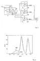
- Fig. 2 shows the result of measurements made with the circuit.
- uncoated working electrodes have been brought into contact with a solution containing DNA.
- the measurement is carried out by means of differential pulse voltammetry. Placed in Fig. 2 is above the voltage the measured at the working electrode current difference before and after a voltage modulation.
- the left peak shows the oxidation of guanine from DNA adsorbed on the working electrode.
- the right peak shows the oxidation of adenine.
- the results are plotted which have been obtained by measurement at a first working electrode AE1 and at a second working electrode AE2.
- the present measurement only shows nonspecific detection of DNA in a solution.
- a suitable coating of the working electrodes it is possible within the scope of the invention to detect specifically predetermined DNA or the like in a solution.
- the number of specific DNA sequences to be detected or the like depends on the number of working electrodes used.
Description
- Die Erfindung betrifft eine Vorrichtung und ein Verfahren zum elektrochemischen Nachweis zumindest eines in einer Flüssigkeit enthaltenen biochemischen Moleküls aus einer Gruppe vorgegebener biochemischer Moleküle. Die Erfindung betrifft insbesondere eine Vorrichtung zum Nachweis von Krankheitserregern in einer Körperflüssigkeit, z. B. Blut.
- Zur Messung elektrochemischer P-otenziale werden nach dem Stand der Technik Potentiostaten mit zwei oder mehreren Arbeitselektroden verwendet. Potentiostaten mit mehreren Arbeitselektroden werden auch als Multipotentiostaten bezeichnet. Solche Multipotentiostaten weisen eine Referenzelektrode, eine Gegenelektrode und mehrere Arbeitselektroden auf. Die Spannung zwischen einer Arbeitselektrode und der Referenzelektrode wird über die zwischen der Gegenelektrode und der jeweiligen Arbeitselektrode anliegende Spannung geregelt. Ein vorgegebener Spannungsverlauf zwischen jeder der Arbeitselektroden und der Referenzelektrode wird für jede Arbeitselektrode separat erzeugt.
- Aus der
US 5,830,343 ist ein Verfahren bekannt, bei dem mittels eines Multipotentiostaten simultan die über eine Vielzahl von Arbeitselektroden abfallende Spannung gemessen werden kann. Dabei wird jede Arbeitselektrode unabhängig von den anderen mit einem besonderen vorgegebenen Potenzial gegen die Referenzelektrode beaufschlagt. Infolgedessen bilden sich während der Messung zwischen den Arbeitselektroden Potenziale aus. Das macht die Auswertung der an den übrigen Arbeitselektroden gemessenen Ströme kompliziert. - Aus der
US 5,149,629 ist ein Verfahren zur elektrochemischen Detektion von in einer Lösung enthaltenen Molekülen bekannt, bei dem sequenziell mit mehreren Arbeitselektroden gemessen wird. Die Durchführung einer solchen Messung ist zeitaufwändig. - Die
US 4,315,753 beschreibt ein Verfahren und eine Vorrichtung zur gleichzeitigen Ermittlung der Konzentration zweiter sauerstoffhaltiger Gase. Die Vorrichtung weist einen Potentiostaten mit zwei Stromfolgern auf, die zur Erzeugung eines Differenzsignals miteinander verschalten sind. Mit der bekannten Vorrichtung ist es nicht möglich, mehrere in einer Lösung enthaltene biochemische Moleküle spezifisch nachzuweisen. - Die
US 4,655,880 offenbart eine Vorrichtung zum Nachweis von Glucose. Dabei werden zwei Arbeitselektroden verwendet, von denen eine mit dem Glucose-Oxidase-Enzym beschichtet ist. Die andere Arbeitselektrode ist unbeschichtet und dient der Messung des Untergrunds. Eine simultane Messung unterschiedlicher biochemischer Moleküle ist mit der bekannten Vorrichtung nicht möglich. - Aus Paeschke, Manfred et al.: Voltammetric Multichannel Measurements Using Silicon Fabricated Microelectrode Arrays; in: Electroanalysis 1996, 8, Nr. 10; Seiten 891 bis 898 ist ein voltammetrisches Verfahren unter Verwendung eines Vielkanalpotentiostaten beschrieben. Der beschriebene Vielkanalpotentiostat ist aufwändig herzustellen. Abgesehen davon, ergeben sich in der Praxis bei der Messung häufig Stabilitätsprobleme. Ein spezifischer Nachweis von in einer Lösung enthaltenen biochemischen Molekülen ist damit nur eingeschränkt möglich.
- Die
DE 41 36 779 A1 beschreibt eine Vorrichtung zum simultanen Nachweis verschiedener Gaskomponenten. Die Vorrichtung umfasst verschiedene Arbeitselektroden, eine gemeinsame Gegenelektrode sowie eine gemeinsame Referenzelektrode. Mit der Vorrichtung kann das Potenzial jeder Arbeitselektrode separat geregelt werden. Die entsprechende Regelungsschaltung ist kompliziert und störanfällig. - Aus der
DE 100 15 818 A1 ist ein Biosensor bekannt. Zum Nachweis eines in einer Lösung enthaltenen Analyten wird dessen Oxidations- und Reduktionspotential an jeweils einer Elektrode gemessen. Es sind also zwei Elektroden pro nachzuweisendem Analyt notwendig. Der vorgeschlagene Biosensor ist relativ aufwändig herzustellen. Ein gleichzeitiger Nachweis mehrerer in einer Flüssigkeit enthaltener biochemischer Moleküle ist damit nicht möglich. - Die
US 2001/0029048 A1 offenbart eine Vorrichtung zum simultanen elektrochemischen Nachweis von in einer Flüssigkeit enthaltenen biochemischen Molekülen mit einem eine Referenzelektrode, eine Gegenelektrode sowie eine Vielzahl von Arbeitselektroden aufweisenden Mittel zur Aufnahme der Flüssigkeit. - Aufgabe der Erfindung ist es, die Nachteile nach dem Stand der Technik zu beseitigen. Es sollen insbesondere eine Vorrichtung und ein Verfahren angegeben werden, mit denen ein simultaner elektrochemischer Nachweis von in einer Flüssigkeit enthaltenen unterschiedlichen biochemischen Molekülen einfach, kostengünstig und schnell durchführbar ist. Nach einem weiteren Ziel der Erfindung sollen möglichst genaue Messergebnisse erzielbar sein.
- Diese Aufgabe wird durch die Merkmale der Ansprüche 1 und 12 gelöst. Zweckmäßige Ausgestaltungen ergeben sich aus den Merkmalen der Ansprüche 2 bis 11, 13 und 14.
- Nach Maßgabe der Erfindung ist eine Vorrichtung zum elektrochemischen Nachweis eines in einer Flüssigkeit enthaltenen biochemischen Moleküls aus einer Gruppe vorgegebener biochemischer Moleküle unterschiedlicher Art vorgesehen mit
einem mindestens eine Referenz- und mindestens eine Gegenelektrode sowie mehr als zwei Arbeitselektroden aufweisenden Mittel zur Aufnahme der Flüssigkeit, wobei zum Nachweis jeder Art eines biochemischen Moleküls zumindest jeweils eine Arbeitselektrode (AE1, AE2, AE3) vorgesehen ist, die mit einem zum nachzuweisenden biochemischen Molekül komplementären Molekül beschichtet ist, so dass biochemische Moleküle unterschiedlicher Art simultan nachweisbar sind,
einem Potentiostaten zur Erzeugung eines vorgegebenen während der Messung veränderlichen Spannungsverlaufs zwischen den Arbeitselektroden und der Referenzelektrode,
wobei jeder der Arbeitselektroden ein Strom-Spannungskonverter nachgeschaltet ist, wobei die Strom-Spannungskonverter sämtliche Arbeitselektroden auf demselben Potenzial halten und
einem Mittel zum Messen der durch die Arbeitselektroden fließenden Ströme. - Die vorgeschlagene Vorrichtung ist einfach aufgebaut. Sie ermöglicht einen schnellen Nachweis zumindest eines in einer Körperflüssigkeit enthaltenen biochemischen Moleküls, z. B. eines Krankheitserregers. Die Vorrichtung lässt sich einfach durch die Wahl einer geeigneten Beschichtung der Arbeitselektrode an die nachzuweisenden biochemischen Moleküle anpassen. Die Art und die Anzahl der in der "Gruppe" enthaltenen biochemischen Moleküle ist durch die Anzahl der mit unterschiedlichen komplementären biochemischen Molekülen beschichteten Arbeitselektroden gegeben. Die Vorrichtung ermöglicht auch einen simultanen elektrochemischen Nachweis mehrerer unterschiedlicher in der Flüssigkeit enthaltener biochemischer Moleküle. Zum simultanen Nachweis unterschiedlicher nachzuweisender biochemischer Moleküle ist lediglich ein einziger Potentiostat erforderlich. Damit wird an sämtliche Arbeitselektroden gleichzeitig ein identischer vorgegebener Spannungsverlauf angelegt. Indem sämtliche Arbeitselektroden auf demselben Potenzial gehalten werden, ist es möglich, die durch die Arbeitselektroden fließenden Ströme parallel zu messen. Dazu kann jede der Arbeitselektroden über einen Stromfolger zur individuellen Auswertung der Signale virtuell an der Schaltungsmasse anliegen. Zum spezifischen Nachweis der in der Flüssigkeit enthaltenen biochemischen Moleküle sind die Arbeitselektroden mit zum nachzuweisenden biochemischen Molekül komplementären biochemischen Molekülen beschichtet. Die Arbeitselektroden sind spezifisch für die nachzuweisenden biochemischen Molekülen. Für jedes nachzuweisende biochemische Molekül ist zumindest eine spezifische Arbeitselektrode vorgesehen. Die komplementären biochemischen Moleküle binden spezifisch an den nachzuweisenden biochemischen Moleküle. Infolge der Ausbildung einer aus dem nachzuweisenden biochemischen Molekül und dem komplementären biochemischen Molekül gebildeten Verbindung ändert sich das elektrochemische Signal der Arbeitselektrode.
- Nach einer vorteilhaften Ausgestaltung sind mehrere miteinander verbundene oder kapazitiv gekoppelte Referenzelektroden vorgesehen. Damit kann die Geschwindigkeit der Messung weiter erhöht werden. In diesem Zusammenhang können auch mehrere miteinander verbundene Gegenelektroden vorgesehen sein.
- Zweckmäßigerweise weist das Mittel zum Messen einen Analog-Digital-Wandler auf. Ferner kann ein Multiplexer vorgesehen sein, so dass eine quasi zeitgleiche bzw. simultane Messung der durch die Arbeitselektroden fließenden Ströme möglich ist.
- Nach einer weiteren Ausgestaltung ist der Strom-Spannungskonverter ein einen ersten Operationsverstärker aufweisender Stromfolger, wobei ein nichtinvertierender Eingang des Operationsverstärkers an der Masse anliegt und dessen invertierender Eingang über einen ersten Widerstand mit dem Ausgang des ersten Operationsverstärkers und mit der Arbeitselektrode verbunden ist. Parallel zum ersten Widerstand kann eine Kapazität geschaltet sein. Damit kann auf einfache Weise ein Rauschen unterdrücktund somit die Sensitivität gesteigert werden.
Zur Einstellung des Strommessbereichs können unterschiedlich große erste Widerstände zwischen dem invertierenden Eingang und dem Ausgang des ersten Operationsverstärkers einschaltbar sein. Damit kann in einfacher Weise der Strommessbereich variiert werden. Der Strommessbereich kann für jede Arbeitselektrode individuell auf den für das nachzuweisende biochemische Molekül optimalen Bereich eingestellt werden. Die Vorrichtung ist universell für den Nachweis unterschiedlichster biochemischer Moleküle geeignet. - Beim nachzuweisenden biochemischen Molekül kann es sich um eine Nukleinsäure und beim komplementären biochemischen Molekül um zur nachzuweisenden Nukleinsäure komplementäre Nukleinsäuren handeln. Im Falle einer Hybridisierung solcher Nukleinsäuren ändert sich der Stromverlauf durch die entsprechende Arbeitselektrode. Eine solche Änderung zeigt an, dass in der Lösung eine Nukleinsäure enthalten ist, welche zur an der Arbeitselektrode gebundenen Nukleinsäure komplementär ist. Ein solcher Nachweis ist hoch sensitiv und äußerst spezifisch. Bei den biochemischen Molekülen kann es sich auch um synthetische einzelsträngige Nukleinsäuren oder deren natürliche und/oder synthetische Analoga, Antigene, Proteine, wie Antikörper, Antikörperfragmente, Derivate von Antikörpern oder Antikörperfragmenten, Nukleinsäure-bindende Proteine, Rezeptoren oder Liganden handeln.
- In weiterer Ausgestaltung weist der Potentiostat einen als Spannungsfolger geschalteten zweiten Operationsverstärker auf, an dessen nicht invertierendem Eingang die Referenzelektrode angeschlossen ist. Der Potentiostat kann ferner einen dritten Operationsverstärker aufweisen, an dessen Ausgang die Gegenelektrode angeschlossen ist, dessen invertierender Eingang über einen zweiten Widerstand mit dem Ausgang des zweiten Operationsverstärkers verbunden und über einen dritten Widerstand mit einer Einrichtung zur Erzeugung einer wählbaren Sollspannung angeschlossen ist, und wobei der nichtinvertierende Eingang des dritten Operationsverstärkers an der Masse anliegt. Des Weiteren kann zwischen dem Ausgang des dritten Operationsverstärkers und dessen invertierenden Eingang eine Kapazität eingeschaltet sein. Das bewirkt eine Stabilisierung der Regelung.
- Nach weiterer Maßgabe der Erfindung ist ein Verfahren zum elektrochemischen Nachweis zumindest einer Art eines in einer Flüssigkeit enthaltenen biochemischen Moleküls aus einer Gruppe vorgegebener biochemischer Moleküle unterschiedlicher Art mit folgenden Schritten vorgesehen:
- a) Bereitstellen eines Mittels zur Aufnahme der Flüssigkeit, wobei das Mittel mindestens eine Gegen- und eine Referenzelektrode sowie mehr als zwei Arbeitselektroden aufweist, wobei zum Nachweis jedes biochemischen Moleküls zumindest jeweils eine Arbeitselektrode (AE1, AE2, AE3) vorgesehen ist, die mit einem zum nachzuweisenden biochemischen Molekül komplementären Molekül beschichtet ist, so dass die biochemischen Moleküle unterschiedlicher Art simultan nachweisbar sind,
- b) Inkontaktbringen der Flüssigkeit mit den Arbeits-, Gegen- und Referenzelektroden,
- c) gleichzeitiges Anlegen eines vorgegebenen während der Messung veränderlichen Spannungsverlaufs zwischen den Arbeitselektroden und der Referenzelektrode und
- d) Messen der durch die Arbeitselektroden fließenden Ströme, wobei während der Messung sämtliche Arbeitselektroden auf demselben Potenzial gehalten werden.
- Die Messung erfolgt quasi zeitgleich bzw. simultan. Sie wird zweckmäßigerweise parallel oder mittels Multiplexen durchgeführt. Dabei kann die zwischen den Arbeitselektroden und der Referenzelektrode anliegende Spannung mit einem Potentiostaten geregelt werden. Das vorgeschlagene Verfahren ist relativ einfach durchführbar. Es ist universell und ermöglicht auch den simultanen Nachweis einer Vielzahl unterschiedlicher biochemischer Moleküle in einer Flüssigkeit.
- Bei dem vorgegebenen Spannungsverlauf handelt es sich um einen während der Messung veränderlichen Spannungsverlauf. Der Spannungsverlauf kann mittels einer programmierbaren Spannungsquelle vorgegeben werden.
- Die Elektroden können aus herkömmlichen Materialien, beispielsweise geeigneten Metallen wie Gold, Silber, Platin oder dgl. hergestellt sein. Es ist aber auch möglich, die Elektroden aus Kohlenstoff, insbesondere Grafit, herzustellen. Die Beschichtung der Elektroden erfolgt in herkömmlicher Weise, im Falle von Nukleinsäuren beispielsweise durch Ausbildung von kovalenten Bindungen. Es wird verwiesen auf MI Pividori, et al. (2000) Electrochemical genosensor design: Immobilisation of oligonucleotides onto transducer surfaces and detection methods. Biosensors and Bioelectronics 15, 291-303 .
- Ein Ausführungsbeispiel der Erfindung wird anhand der Zeichnung näher erläutert. Es zeigen:
- Fig. 1
- ein schematisches Schaltbild und
- Fig. 2
- ein mit der Schaltung gemäß
Fig. 1 erzieltes Messergebnis. - Ein Mittel zur Aufnahme der die nachzuweisenden biochemischen Moleküle enthaltenden Flüssigkeit kann z.B. ein Behälter oder ein Feld auf einer aus einem isolierenden Material hergestellten Fläche, z.B. auf einem Chip, sein. Der Behälter weist Arbeitselektroden AE1, AE2, AE3, eine Gegenelektrode GE sowie eine Referenzelektrode RE auf. Die Elektroden sind z.B. aus Silber, Gold, Platin oder Grafit hergestellt. Die Arbeitselektroden AE1, AE2, AE3 sind mit zu den nachzuweisenden biochemischen Molekülen komplementären Moleküle beschichtet.
- Jede der Arbeitselektroden AE1, AE2, AE3 ist über eine Strom-Spannungskonverter S1, S2, S3 mit einer Messvorrichtung AD verbunden.
- Die Strom-Spannungskonverter S1, S2, S3 weisen jeweils einen Operationsverstärker OP1 auf, dessen nichtinvertierender Eingang (OP1+) an Schaltungsmasse anliegt. Infolgedessen werden sämtliche Arbeitselektroden AE1, AE2, AE3 auf demselben Potenzial gehalten. Der invertierende Eingang OP1- des ersten Operationsverstärkers OP1 ist mit der Arbeitselektrode AE1, AE2, AE3 und über einen ersten Widerstand R1 mit dem Ausgang verbunden, der wiederum mit der Messvorrichtung AD in Verbindung steht. Zur Rauschunterdrückung kann parallel zum ersten Widerstand R1 eine (hier nicht gezeigte) Kapazität geschaltet sein. Es können unterschiedlich große erste Widerstände R1 vorgesehen sein, welche alternativ einschaltbar sind. So kann auf einfache Weise der Messbereich geändert werden.
- Mit dem Bezugszeichen P ist ein Potentiostat bezeichnet, dessen Eingang mit einer (hier nicht gezeigten) programmierbaren Spannungsquelle verbunden ist. Der Potentiostat P umfasst einen als Spannungsfolger geschalteten zweiten Operationsverstärker OP2 und einen dritten Operationsverstärker OP3. Der nichtinvertierende Eingang OP2+ des zweiten Operationsverstärkers OP2 ist an die Referenzelektrode RE angeschlossen. Der invertierende Eingang OP2- des zweiten Operationsverstärkers OP2 ist mit dessen Ausgang und über einen zweiten Widerstand mit dem invertierenden Eingang OP3- des dritten Operationsverstärkers OP3 verbunden. Der nichtinvertierende Eingang OP3+ des dritten Operationsverstärkers liegt an Schaltungsmasse. Die (hier nicht gezeigte) programmierbare Spannungsquelle ist über einen dritten Widerstand R3 mit dem invertierenden Eingang OP3- des dritten Operationsverstärkers OP3 sowie dem zweiten Widerstand OP2 verbunden. Der Ausgang des dritten Operationsverstärkers OP3 ist mit der Gegenelektrode GE verbunden. Zwischen dem Ausgang des dritten Operationsverstärkers OP3 und dessen invertierenden Eingang kann eine (hier nicht gezeigte) weitere Kapazität eingeschaltet sein.
- Bei der Messvorrichtung AD kann es sich um einen Analog-Digital-Wandler mit Multiplexer handeln. Das ermöglicht eine quasi zeitgleiche Messung der durch die Arbeitselektroden AE1, AE2, AE3 fließenden Ströme.
- Indem die Referenzelektrode RE an den nichtinvertierenden Eingang OP2+ des zweiten Operationsverstärkers OP2 angeschlossen ist, erhält man einen Spannungsfolger mit einer sehr hohen Eingangsimpedanz. Ein durch die Referenzelektrode RE fließender Elektrolysestrom wird damit wirkungsvoll unterbunden. Infolgedessen wird eine besonders genaue Messung erreicht.
- Der mit der Gegenelektrode GE verbundene Ausgang des dritten Operationsverstärkers OP3 wird im Betrieb so angesteuert, dass zwischen dessen Eingängen OP3-, OP3+ keine Spannung anliegt. Der nichtinvertierende Eingang OP3+ des dritten Operationsverstärkers OP3 liegt an Schaltungsmasse an. Infolgedessen liegt auch der invertierende Eingang OP3- virtuell auf Masse und damit auf demselben Potenzial wie die Arbeitselektroden AE1, AE2, AE3. Bei geeigneter Regelung ist der durch den dritten Widerstand R3 fließende Strom gleich dem durch den zweiten Widerstand R2 fließenden Strom. Da die Spannung über dem zweiten Widerstand R2 dem Betrag nach gleich der Spannung zwischen der Referenzelektrode RE und den Arbeitselektroden AE1, AE2, AE3 ist, kann das Potenzial der Arbeitselektroden AE1, AE2, AE3 gegen die Referenzelektrode RE durch eine proportionale Spannung am Eingang U des Potentiostaten P vorgegeben werden. In der Praxis wird zweckmäßigerweise der zweite Widerstand R2 gleich dem dritten Widerstand R3 gewählt, wodurch die Proportionalitätskonstante auf den Wert -1 festgelegt wird. Alternativ kann in diesem Fall eines addierenden Potentiostaten P der dritte Widerstand R3 durch mehrere Widerstände ersetzt werden, wodurch mehrere Eingänge, z.B. zur Modulation, erhalten werden.
- Nach einer Variation an der Schaltung ist es möglich, die Strom-Spannungskonverter S1, S2, S3 im Frequenzgang zu beschränken. Dadurch kann das Gesamtrauschen vermindert werden. Eine solche Beschränkung im Frequenzgang kann durch Kondensatoren erreicht werden, die jeweils parallel zum ersten Widerstand R1 geschaltet werden. Zur Vergrößerung des Strommessbereichs kann es von Vorteil sein, die ersten Widerstände R1, ggf. mit dazu parallel geschalteten Kondensatoren, mittels Relais oder analoger elektronischer Schalter oder einer Kombination der beiden schaltbar auszuführen.
-
Fig. 2 zeigt das Ergebnis von mit der Schaltung durchgeführten Messungen. Dazu sind unbeschichtete Arbeitselektroden mit einer DNA enthaltenden Lösung in Kontakt gebracht worden. Die Messung ist erfolgt mittels Differenzialpulsvoltammetrie. Aufgetragen inFig. 2 ist über der Spannung die an der Arbeitselektrode gemessene Stromdifferenz jeweils vor und nach einer Spannungsmodulation. Der linke Peak zeigt die Oxidation von Guanin von an der Arbeitselektrode adsorbierter DNA. Der rechte Peak zeigt die Oxidation von Adenin. Es sind die Ergebnisse aufgetragen welche durch Messung an einer ersten Arbeitselektrode AE1 und an einer zweiten Arbeitselektrode AE2 gewonnen worden sind. - Die vorliegende Messung zeigt lediglich einen unspezifischen Nachweis von DNA in einer Lösung. Bei einer geeigneten Beschichtung der Arbeitselektroden ist es im Rahmen der Erfindung möglich, spezifisch vorgegebene DNA oder dgl. in einer Lösung nachzuweisen. Die Anzahl der spezifisch nachzuweisenden DNA-Sequenzen oder dgl. hängt ab von der Anzahl der verwendeten Arbeitselektroden.
-
- OP1, 2, 3
- erster, zweiter, dritter Operationsverstärker
- P
- Potentiostat
- S1, 2, 3
- erster, zweiter, dritter Strom-Spannungskonverter
- R1, 2, 3
- erster, zweiter, dritter Widerstand
- AD
- Messvorrichtung
- AE1, 2, 3
- Arbeitselektroden
- GE
- Gegenelektrode
- RE
- Referenzelektrode
- U
- Ausgang einer programmierbaren Spannungsquelle
Claims (14)
- Vorrichtung zum elektrochemischen Nachweis zumindest einer Art- eines in einer Flüssigkeit enthaltenen biochemischen Moleküles aus einer Gruppe vorgegebener biochemischer Moleküle unterschiedlicher Art mit
einem mindestens eine Referenz- (RE) und mindestens eine Gegenelektrode (GE) sowie mehr als zwei Arbeitselektroden (AE1, AE2, AE3) aufweisenden Mittel (1) zur Aufnahme der Flüssigkeit, wobei zum Nachweis jeder Art eines biochemischen Moleküls zumindest jeweils eine Arbeitselektrode (AE1, AE2, AE3) vorgesehen ist, die mit einem zum nachzuweisenden biochemischen Molekül komplementären Molekül beschichtet ist, so dass biochemische Moleküle unterschiedlicher Art simultan nachweisbar sind,
einem Potentiostaten (P) zur Erzeugung eines vorgegebenen während der Messung veränderlichen Spannungsverlaufs zwischen den Arbeitselektroden (AE1, AE2, AE3) und der Referenzelektrode (RE),
wobei jeder der Arbeitselektroden (AE1, AE2, AE3) ein StromSpannungskonverter (S1, S2, S3) nachgeschaltet ist, wobei die Strom-Spannungskonverter (S1, S2, S3) sämtliche Arbeitselektroden (AE1, AE2, AE3) auf demselben Potenzial halten, und
einem Mittel (S1, S2, S3 AD) zum Messen der durch die Arbeitselektroden (AE1, AE2, AE3) fließenden Ströme. - Vorrichtung nach Anspruch 1, wobei mehrere miteinander verbundene oder kapazitiv gekoppelte Referenzelektroden (RE) vorgesehen sind.
- Vorrichtung nach Anspruch 1 oder 2, wobei mehrere miteinander verbundene Gegenelektroden (GE) vorgesehen sind.
- Vorrichtung nach einem der vorhergehenden Ansprüche, wobei das Mittel (AD) zum Messen einen Analog-Digital-Wandler aufweist.
- Vorrichtung nach einem der vorhergehenden Ansprüche, wobei der Strom-Spannungskonverter (S1, S2, S3) ein einen ersten Operationsverstärker (OP1) aufweisenden Stromfolger ist, wobei ein nichtinvertierender Eingang (OP1+) des ersten Operationsverstärkers (OP1) an Masse anliegt und dessen invertierender Eingang (OP1-) über einen ersten Widerstand (R1) mit dem Ausgang des ersten Operationsverstärkers (OP1) und mit der Arbeitselektrode (AE1) verbunden ist.
- Vorrichtung nach Anspruch 5, wobei parallel zum ersten Widerstand (R1) eine Kapazität geschaltet ist.
- Vorrichtung nach einem der Ansprüche 5 oder 6, wobei zur Einstellung des Strommessbereichs unterschiedlich große erste Widerstände (R1) zwischen den invertierenden Eingang (OP1-) und den Ausgang des ersten Operationsverstärkers (OP1) einschaltbar sind.
- Vorrichtung nach einem der vorhergehenden Ansprüche, wobei das nachzuweisende biochemische Molekül eine Nukleinsäure und die komplementären biochemischen Moleküle zur nachzuweisenden Nukleinsäure komplementäre Nukleinsäuren sind.
- Vorrichtung nach einem der Ansprüche 5-7, wobei der Potentiostat (P) einen als Spannungsfolger geschalteten zweiten Operationsverstärker (OP2) aufweist, an dessen nichtinvertierendem Eingang (OP2+) die Referenzelektrode (RE) angeschlossen ist.
- Vorrichtung nach Anspruch 9, wobei der Potentiostat (P) einen dritten Operationsverstärker (OP3) aufweist, an dessen Ausgang die Gegenelektrode (GE) angeschlossen ist, dessen invertierender Eingang (OP3-) über einen zweiten Widerstand (R2) mit dem Ausgang des zweiten Operationsverstärkers (OP2) verbunden und über einen dritten Widerstand (R3) an einer Einrichtung zur Erzeugung einer wählbaren Sollspannung angeschlossen ist, und wobei der nichtinvertierende Eingang (OP3+) des dritten Operationsverstärkers (OP3) an Masse anliegt.
- Vorrichtung nach Anspruch 10, wobei zwischen dem Ausgang des dritten Operationsverstärkers (OP3) und dessen invertierenden Eingang (OP3-) eine Kapazität eingeschaltet ist.
- Verfahren zum elektrochemischen Nachweis zumindest einer Art eines in einer Flüssigkeit enthaltenen biochemischen Moleküls aus einer Gruppe vorgegebener biochemischer Moleküle unterschiedlicher Art mit folgenden Schritten:a) Bereitstellen eines Mittels (1) zur Aufnahme der Flüssigkeit, wobei das Mittel (1) mindestens eine Gegen- (GE) und eine Referenzelektrode (RE) sowie mehr als zwei Arbeitselektroden (AE1, AE2, AE3) aufweist, wobei zum Nachweis jedes biochemischen Moleküls zumindest jeweils eine Arbeitselektrode (AE1, AE2, AE3) vorgesehen ist, die mit einem zum nachzuweisenden biochemischen Molekül komplementären Molekül beschichtet ist, so dass biochemische Moleküle unterschiedlicher Art simultan nachweisbar sind,b) Inkontaktbringen der Flüssigkeit mit den Arbeits- (AE1, AE2, AE3), Gegen- (GE) und Referenzelektroden (RE),c) gleichzeitiges Anlegen eines vorgegebenen während der Messung veränderlichen Spannungsverlaufs zwischen den Arbeitselektroden (AE1, AE2, AE3) und der Referenzelektrode (RE) undd) Messen der durch die Arbeitselektroden (AE1, AE2, AE3) fließenden Ströme, wobei während der Messung sämtliche Arbeitselektroden (AE1, AE2, AE3) auf demselben Potenzial gehalten werden.
- Verfahren nach Anspruch 12, wobei das Messen parallel oder mittels Multiplexen durchgeführt wird.
- Verfahren nach einem der Ansprüche 12 oder 13, wobei die zwischen den Arbeitselektroden (AE1, AE2, AE3) und der Referenzelektrode (RE) anliegende Spannung mit einem Potentiostaten (P) geregelt wird.
Applications Claiming Priority (5)
| Application Number | Priority Date | Filing Date | Title |
|---|---|---|---|
| DE10229210A DE10229210A1 (de) | 2002-06-28 | 2002-06-28 | Vorrichtung zur Detektion eines Analyten |
| DE10229210 | 2002-06-28 | ||
| DE2002129374 DE10229374C1 (de) | 2002-06-29 | 2002-06-29 | Vorrichtung und Verfahren zum elektrochemischen Nachweis |
| DE10229374 | 2002-06-29 | ||
| PCT/EP2003/006566 WO2004003556A1 (de) | 2002-06-28 | 2003-06-23 | Vorrichtung und verfahren zum elektrochemischen nachweis |
Publications (2)
| Publication Number | Publication Date |
|---|---|
| EP1518123A1 EP1518123A1 (de) | 2005-03-30 |
| EP1518123B1 true EP1518123B1 (de) | 2008-10-29 |
Family
ID=30001494
Family Applications (1)
| Application Number | Title | Priority Date | Filing Date |
|---|---|---|---|
| EP03740302A Expired - Lifetime EP1518123B1 (de) | 2002-06-28 | 2003-06-23 | Vorrichtung und verfahren zum elektrochemischen nachweis |
Country Status (7)
| Country | Link |
|---|---|
| US (1) | US7169289B2 (de) |
| EP (1) | EP1518123B1 (de) |
| JP (1) | JP2005531759A (de) |
| AT (1) | ATE412899T1 (de) |
| AU (1) | AU2003279777A1 (de) |
| DE (1) | DE50310708D1 (de) |
| WO (1) | WO2004003556A1 (de) |
Families Citing this family (146)
| Publication number | Priority date | Publication date | Assignee | Title |
|---|---|---|---|---|
| US7192450B2 (en) | 2003-05-21 | 2007-03-20 | Dexcom, Inc. | Porous membranes for use with implantable devices |
| US7657297B2 (en) * | 2004-05-03 | 2010-02-02 | Dexcom, Inc. | Implantable analyte sensor |
| US6001067A (en) | 1997-03-04 | 1999-12-14 | Shults; Mark C. | Device and method for determining analyte levels |
| US6862465B2 (en) | 1997-03-04 | 2005-03-01 | Dexcom, Inc. | Device and method for determining analyte levels |
| US8527026B2 (en) | 1997-03-04 | 2013-09-03 | Dexcom, Inc. | Device and method for determining analyte levels |
| US6036924A (en) | 1997-12-04 | 2000-03-14 | Hewlett-Packard Company | Cassette of lancet cartridges for sampling blood |
| US6391005B1 (en) | 1998-03-30 | 2002-05-21 | Agilent Technologies, Inc. | Apparatus and method for penetration with shaft having a sensor for sensing penetration depth |
| US8465425B2 (en) | 1998-04-30 | 2013-06-18 | Abbott Diabetes Care Inc. | Analyte monitoring device and methods of use |
| US8480580B2 (en) | 1998-04-30 | 2013-07-09 | Abbott Diabetes Care Inc. | Analyte monitoring device and methods of use |
| US9066695B2 (en) | 1998-04-30 | 2015-06-30 | Abbott Diabetes Care Inc. | Analyte monitoring device and methods of use |
| US8688188B2 (en) | 1998-04-30 | 2014-04-01 | Abbott Diabetes Care Inc. | Analyte monitoring device and methods of use |
| US8974386B2 (en) | 1998-04-30 | 2015-03-10 | Abbott Diabetes Care Inc. | Analyte monitoring device and methods of use |
| US6175752B1 (en) | 1998-04-30 | 2001-01-16 | Therasense, Inc. | Analyte monitoring device and methods of use |
| US6949816B2 (en) | 2003-04-21 | 2005-09-27 | Motorola, Inc. | Semiconductor component having first surface area for electrically coupling to a semiconductor chip and second surface area for electrically coupling to a substrate, and method of manufacturing same |
| US8346337B2 (en) | 1998-04-30 | 2013-01-01 | Abbott Diabetes Care Inc. | Analyte monitoring device and methods of use |
| US8641644B2 (en) | 2000-11-21 | 2014-02-04 | Sanofi-Aventis Deutschland Gmbh | Blood testing apparatus having a rotatable cartridge with multiple lancing elements and testing means |
| US6560471B1 (en) | 2001-01-02 | 2003-05-06 | Therasense, Inc. | Analyte monitoring device and methods of use |
| US7749174B2 (en) | 2001-06-12 | 2010-07-06 | Pelikan Technologies, Inc. | Method and apparatus for lancet launching device intergrated onto a blood-sampling cartridge |
| US7041068B2 (en) | 2001-06-12 | 2006-05-09 | Pelikan Technologies, Inc. | Sampling module device and method |
| US9427532B2 (en) | 2001-06-12 | 2016-08-30 | Sanofi-Aventis Deutschland Gmbh | Tissue penetration device |
| CA2448902C (en) | 2001-06-12 | 2010-09-07 | Pelikan Technologies, Inc. | Self optimizing lancing device with adaptation means to temporal variations in cutaneous properties |
| US7699791B2 (en) | 2001-06-12 | 2010-04-20 | Pelikan Technologies, Inc. | Method and apparatus for improving success rate of blood yield from a fingerstick |
| US9226699B2 (en) | 2002-04-19 | 2016-01-05 | Sanofi-Aventis Deutschland Gmbh | Body fluid sampling module with a continuous compression tissue interface surface |
| US8337419B2 (en) | 2002-04-19 | 2012-12-25 | Sanofi-Aventis Deutschland Gmbh | Tissue penetration device |
| US9795747B2 (en) | 2010-06-02 | 2017-10-24 | Sanofi-Aventis Deutschland Gmbh | Methods and apparatus for lancet actuation |
| US7344507B2 (en) | 2002-04-19 | 2008-03-18 | Pelikan Technologies, Inc. | Method and apparatus for lancet actuation |
| US7981056B2 (en) | 2002-04-19 | 2011-07-19 | Pelikan Technologies, Inc. | Methods and apparatus for lancet actuation |
| US7033371B2 (en) | 2001-06-12 | 2006-04-25 | Pelikan Technologies, Inc. | Electric lancet actuator |
| DE60234597D1 (de) | 2001-06-12 | 2010-01-14 | Pelikan Technologies Inc | Gerät und verfahren zur entnahme von blutproben |
| US20030032874A1 (en) | 2001-07-27 | 2003-02-13 | Dexcom, Inc. | Sensor head for use with implantable devices |
| US6702857B2 (en) | 2001-07-27 | 2004-03-09 | Dexcom, Inc. | Membrane for use with implantable devices |
| US8260393B2 (en) | 2003-07-25 | 2012-09-04 | Dexcom, Inc. | Systems and methods for replacing signal data artifacts in a glucose sensor data stream |
| US9247901B2 (en) | 2003-08-22 | 2016-02-02 | Dexcom, Inc. | Systems and methods for replacing signal artifacts in a glucose sensor data stream |
| US8010174B2 (en) | 2003-08-22 | 2011-08-30 | Dexcom, Inc. | Systems and methods for replacing signal artifacts in a glucose sensor data stream |
| US10022078B2 (en) * | 2004-07-13 | 2018-07-17 | Dexcom, Inc. | Analyte sensor |
| US9282925B2 (en) | 2002-02-12 | 2016-03-15 | Dexcom, Inc. | Systems and methods for replacing signal artifacts in a glucose sensor data stream |
| US7226461B2 (en) | 2002-04-19 | 2007-06-05 | Pelikan Technologies, Inc. | Method and apparatus for a multi-use body fluid sampling device with sterility barrier release |
| US7491178B2 (en) | 2002-04-19 | 2009-02-17 | Pelikan Technologies, Inc. | Method and apparatus for penetrating tissue |
| US7892183B2 (en) | 2002-04-19 | 2011-02-22 | Pelikan Technologies, Inc. | Method and apparatus for body fluid sampling and analyte sensing |
| US9314194B2 (en) | 2002-04-19 | 2016-04-19 | Sanofi-Aventis Deutschland Gmbh | Tissue penetration device |
| US7331931B2 (en) | 2002-04-19 | 2008-02-19 | Pelikan Technologies, Inc. | Method and apparatus for penetrating tissue |
| US8221334B2 (en) | 2002-04-19 | 2012-07-17 | Sanofi-Aventis Deutschland Gmbh | Method and apparatus for penetrating tissue |
| US7909778B2 (en) | 2002-04-19 | 2011-03-22 | Pelikan Technologies, Inc. | Method and apparatus for penetrating tissue |
| US7229458B2 (en) | 2002-04-19 | 2007-06-12 | Pelikan Technologies, Inc. | Method and apparatus for penetrating tissue |
| US7232451B2 (en) | 2002-04-19 | 2007-06-19 | Pelikan Technologies, Inc. | Method and apparatus for penetrating tissue |
| US7976476B2 (en) | 2002-04-19 | 2011-07-12 | Pelikan Technologies, Inc. | Device and method for variable speed lancet |
| US7648468B2 (en) * | 2002-04-19 | 2010-01-19 | Pelikon Technologies, Inc. | Method and apparatus for penetrating tissue |
| US8784335B2 (en) | 2002-04-19 | 2014-07-22 | Sanofi-Aventis Deutschland Gmbh | Body fluid sampling device with a capacitive sensor |
| US7371247B2 (en) | 2002-04-19 | 2008-05-13 | Pelikan Technologies, Inc | Method and apparatus for penetrating tissue |
| US7901362B2 (en) | 2002-04-19 | 2011-03-08 | Pelikan Technologies, Inc. | Method and apparatus for penetrating tissue |
| US8702624B2 (en) | 2006-09-29 | 2014-04-22 | Sanofi-Aventis Deutschland Gmbh | Analyte measurement device with a single shot actuator |
| US7291117B2 (en) | 2002-04-19 | 2007-11-06 | Pelikan Technologies, Inc. | Method and apparatus for penetrating tissue |
| US8267870B2 (en) | 2002-04-19 | 2012-09-18 | Sanofi-Aventis Deutschland Gmbh | Method and apparatus for body fluid sampling with hybrid actuation |
| US9248267B2 (en) | 2002-04-19 | 2016-02-02 | Sanofi-Aventis Deustchland Gmbh | Tissue penetration device |
| US7297122B2 (en) | 2002-04-19 | 2007-11-20 | Pelikan Technologies, Inc. | Method and apparatus for penetrating tissue |
| US8372016B2 (en) * | 2002-04-19 | 2013-02-12 | Sanofi-Aventis Deutschland Gmbh | Method and apparatus for body fluid sampling and analyte sensing |
| US7547287B2 (en) | 2002-04-19 | 2009-06-16 | Pelikan Technologies, Inc. | Method and apparatus for penetrating tissue |
| US8360992B2 (en) | 2002-04-19 | 2013-01-29 | Sanofi-Aventis Deutschland Gmbh | Method and apparatus for penetrating tissue |
| US7717863B2 (en) | 2002-04-19 | 2010-05-18 | Pelikan Technologies, Inc. | Method and apparatus for penetrating tissue |
| US7674232B2 (en) | 2002-04-19 | 2010-03-09 | Pelikan Technologies, Inc. | Method and apparatus for penetrating tissue |
| US9795334B2 (en) | 2002-04-19 | 2017-10-24 | Sanofi-Aventis Deutschland Gmbh | Method and apparatus for penetrating tissue |
| US8579831B2 (en) | 2002-04-19 | 2013-11-12 | Sanofi-Aventis Deutschland Gmbh | Method and apparatus for penetrating tissue |
| US8574895B2 (en) | 2002-12-30 | 2013-11-05 | Sanofi-Aventis Deutschland Gmbh | Method and apparatus using optical techniques to measure analyte levels |
| US7134999B2 (en) | 2003-04-04 | 2006-11-14 | Dexcom, Inc. | Optimized sensor geometry for an implantable glucose sensor |
| EP1620021A4 (de) * | 2003-05-02 | 2008-06-18 | Pelikan Technologies Inc | Verfahren und gerät für eine anwenderschnittstelle für eine gewebepenetrationsvorrichtung |
| US7875293B2 (en) * | 2003-05-21 | 2011-01-25 | Dexcom, Inc. | Biointerface membranes incorporating bioactive agents |
| ES2347248T3 (es) | 2003-05-30 | 2010-10-27 | Pelikan Technologies Inc. | Procedimiento y aparato para la inyeccion de fluido. |
| WO2004107964A2 (en) | 2003-06-06 | 2004-12-16 | Pelikan Technologies, Inc. | Blood harvesting device with electronic control |
| WO2006001797A1 (en) | 2004-06-14 | 2006-01-05 | Pelikan Technologies, Inc. | Low pain penetrating |
| JP2007500336A (ja) | 2003-07-25 | 2007-01-11 | デックスコム・インコーポレーテッド | 電気化学センサーに用いる電極システム |
| US8423113B2 (en) | 2003-07-25 | 2013-04-16 | Dexcom, Inc. | Systems and methods for processing sensor data |
| US8282549B2 (en) | 2003-12-09 | 2012-10-09 | Dexcom, Inc. | Signal processing for continuous analyte sensor |
| US7933639B2 (en) | 2003-08-01 | 2011-04-26 | Dexcom, Inc. | System and methods for processing analyte sensor data |
| US20100168657A1 (en) * | 2003-08-01 | 2010-07-01 | Dexcom, Inc. | System and methods for processing analyte sensor data |
| US7276029B2 (en) | 2003-08-01 | 2007-10-02 | Dexcom, Inc. | System and methods for processing analyte sensor data |
| US9135402B2 (en) | 2007-12-17 | 2015-09-15 | Dexcom, Inc. | Systems and methods for processing sensor data |
| US7591801B2 (en) | 2004-02-26 | 2009-09-22 | Dexcom, Inc. | Integrated delivery device for continuous glucose sensor |
| US20190357827A1 (en) | 2003-08-01 | 2019-11-28 | Dexcom, Inc. | Analyte sensor |
| US7494465B2 (en) | 2004-07-13 | 2009-02-24 | Dexcom, Inc. | Transcutaneous analyte sensor |
| US7519408B2 (en) | 2003-11-19 | 2009-04-14 | Dexcom, Inc. | Integrated receiver for continuous analyte sensor |
| US8761856B2 (en) | 2003-08-01 | 2014-06-24 | Dexcom, Inc. | System and methods for processing analyte sensor data |
| US8275437B2 (en) | 2003-08-01 | 2012-09-25 | Dexcom, Inc. | Transcutaneous analyte sensor |
| US7774145B2 (en) | 2003-08-01 | 2010-08-10 | Dexcom, Inc. | Transcutaneous analyte sensor |
| US20070208245A1 (en) * | 2003-08-01 | 2007-09-06 | Brauker James H | Transcutaneous analyte sensor |
| US8369919B2 (en) | 2003-08-01 | 2013-02-05 | Dexcom, Inc. | Systems and methods for processing sensor data |
| US8160669B2 (en) | 2003-08-01 | 2012-04-17 | Dexcom, Inc. | Transcutaneous analyte sensor |
| US8845536B2 (en) | 2003-08-01 | 2014-09-30 | Dexcom, Inc. | Transcutaneous analyte sensor |
| US20140121989A1 (en) | 2003-08-22 | 2014-05-01 | Dexcom, Inc. | Systems and methods for processing analyte sensor data |
| US7920906B2 (en) | 2005-03-10 | 2011-04-05 | Dexcom, Inc. | System and methods for processing analyte sensor data for sensor calibration |
| WO2005033659A2 (en) | 2003-09-29 | 2005-04-14 | Pelikan Technologies, Inc. | Method and apparatus for an improved sample capture device |
| US9351680B2 (en) | 2003-10-14 | 2016-05-31 | Sanofi-Aventis Deutschland Gmbh | Method and apparatus for a variable user interface |
| US20050090607A1 (en) * | 2003-10-28 | 2005-04-28 | Dexcom, Inc. | Silicone composition for biocompatible membrane |
| US9247900B2 (en) | 2004-07-13 | 2016-02-02 | Dexcom, Inc. | Analyte sensor |
| EP2239567B1 (de) | 2003-12-05 | 2015-09-02 | DexCom, Inc. | Kalibrierverfahren für einen kontinuierlichen Analytsensor |
| US8774886B2 (en) | 2006-10-04 | 2014-07-08 | Dexcom, Inc. | Analyte sensor |
| US8364231B2 (en) | 2006-10-04 | 2013-01-29 | Dexcom, Inc. | Analyte sensor |
| US11633133B2 (en) | 2003-12-05 | 2023-04-25 | Dexcom, Inc. | Dual electrode system for a continuous analyte sensor |
| US8423114B2 (en) | 2006-10-04 | 2013-04-16 | Dexcom, Inc. | Dual electrode system for a continuous analyte sensor |
| US8287453B2 (en) | 2003-12-05 | 2012-10-16 | Dexcom, Inc. | Analyte sensor |
| US7822454B1 (en) | 2005-01-03 | 2010-10-26 | Pelikan Technologies, Inc. | Fluid sampling device with improved analyte detecting member configuration |
| EP1706026B1 (de) | 2003-12-31 | 2017-03-01 | Sanofi-Aventis Deutschland GmbH | Verfahren und vorrichtung zur verbesserung der fluidströmung und der probennahme |
| US7637868B2 (en) * | 2004-01-12 | 2009-12-29 | Dexcom, Inc. | Composite material for implantable device |
| US8808228B2 (en) | 2004-02-26 | 2014-08-19 | Dexcom, Inc. | Integrated medicament delivery device for use with continuous analyte sensor |
| US8792955B2 (en) | 2004-05-03 | 2014-07-29 | Dexcom, Inc. | Transcutaneous analyte sensor |
| US20050245799A1 (en) * | 2004-05-03 | 2005-11-03 | Dexcom, Inc. | Implantable analyte sensor |
| US8277713B2 (en) * | 2004-05-03 | 2012-10-02 | Dexcom, Inc. | Implantable analyte sensor |
| US8828203B2 (en) | 2004-05-20 | 2014-09-09 | Sanofi-Aventis Deutschland Gmbh | Printable hydrogels for biosensors |
| US9820684B2 (en) | 2004-06-03 | 2017-11-21 | Sanofi-Aventis Deutschland Gmbh | Method and apparatus for a fluid sampling device |
| US9775553B2 (en) | 2004-06-03 | 2017-10-03 | Sanofi-Aventis Deutschland Gmbh | Method and apparatus for a fluid sampling device |
| US7783333B2 (en) * | 2004-07-13 | 2010-08-24 | Dexcom, Inc. | Transcutaneous medical device with variable stiffness |
| US7640048B2 (en) | 2004-07-13 | 2009-12-29 | Dexcom, Inc. | Analyte sensor |
| US20080242961A1 (en) * | 2004-07-13 | 2008-10-02 | Dexcom, Inc. | Transcutaneous analyte sensor |
| US8452368B2 (en) | 2004-07-13 | 2013-05-28 | Dexcom, Inc. | Transcutaneous analyte sensor |
| US8565848B2 (en) | 2004-07-13 | 2013-10-22 | Dexcom, Inc. | Transcutaneous analyte sensor |
| US20060020192A1 (en) | 2004-07-13 | 2006-01-26 | Dexcom, Inc. | Transcutaneous analyte sensor |
| JP4742544B2 (ja) * | 2004-09-08 | 2011-08-10 | 凸版印刷株式会社 | 遺伝子チェック装置及び方法 |
| US8652831B2 (en) | 2004-12-30 | 2014-02-18 | Sanofi-Aventis Deutschland Gmbh | Method and apparatus for analyte measurement test time |
| US20060167382A1 (en) * | 2004-12-30 | 2006-07-27 | Ajay Deshmukh | Method and apparatus for storing an analyte sampling and measurement device |
| EP1835848A4 (de) * | 2004-12-30 | 2009-07-29 | Pelikan Technologies Inc | Verfahren und gerät für analyten-messungstestzeit |
| CA2595452A1 (en) * | 2005-01-26 | 2006-08-03 | Rapid Laboratory Microsystems Inc. | Method, system and device for obtaining electrochemical measurements |
| CN102360170B (zh) * | 2005-02-10 | 2014-03-12 | Asml荷兰有限公司 | 浸没液体、曝光装置及曝光方法 |
| US8060174B2 (en) | 2005-04-15 | 2011-11-15 | Dexcom, Inc. | Analyte sensing biointerface |
| EP1991110B1 (de) | 2006-03-09 | 2018-11-07 | DexCom, Inc. | Systeme und verfahren zur aufbereitung von analytensensordaten |
| US7920907B2 (en) | 2006-06-07 | 2011-04-05 | Abbott Diabetes Care Inc. | Analyte monitoring system and method |
| EP2152350A4 (de) | 2007-06-08 | 2013-03-27 | Dexcom Inc | Integrierte medikamentenfreisetzungsvorrichtung mit kontinuierlichem analytsensor |
| EP4098177A1 (de) | 2007-10-09 | 2022-12-07 | DexCom, Inc. | Integriertes insulin-abgabesystem mit kontinuierlichem glucosesensor |
| US8417312B2 (en) | 2007-10-25 | 2013-04-09 | Dexcom, Inc. | Systems and methods for processing sensor data |
| FR2923296B1 (fr) * | 2007-11-02 | 2009-11-20 | Commissariat Energie Atomique | Potentiostat multi-voies ayant un potentiel de contre-electrode ajustable. |
| US9839395B2 (en) | 2007-12-17 | 2017-12-12 | Dexcom, Inc. | Systems and methods for processing sensor data |
| US20090209883A1 (en) * | 2008-01-17 | 2009-08-20 | Michael Higgins | Tissue penetrating apparatus |
| CA2715628A1 (en) | 2008-02-21 | 2009-08-27 | Dexcom, Inc. | Systems and methods for processing, transmitting and displaying sensor data |
| US8396528B2 (en) | 2008-03-25 | 2013-03-12 | Dexcom, Inc. | Analyte sensor |
| WO2009126900A1 (en) | 2008-04-11 | 2009-10-15 | Pelikan Technologies, Inc. | Method and apparatus for analyte detecting device |
| US9375169B2 (en) | 2009-01-30 | 2016-06-28 | Sanofi-Aventis Deutschland Gmbh | Cam drive for managing disposable penetrating member actions with a single motor and motor and control system |
| EP2410910A4 (de) | 2009-03-27 | 2014-10-15 | Dexcom Inc | Verfahren und systeme zur förderung eines blutzuckermanagements |
| EP2448485B1 (de) | 2009-07-02 | 2021-08-25 | Dexcom, Inc. | Analytsensor |
| US8604810B2 (en) * | 2009-10-16 | 2013-12-10 | Microchips, Inc. | Multi-channel potentiostat for biosensor arrays |
| US8965476B2 (en) | 2010-04-16 | 2015-02-24 | Sanofi-Aventis Deutschland Gmbh | Tissue penetration device |
| WO2012142502A2 (en) | 2011-04-15 | 2012-10-18 | Dexcom Inc. | Advanced analyte sensor calibration and error detection |
| JP5689020B2 (ja) * | 2011-05-12 | 2015-03-25 | 日置電機株式会社 | 微量成分検出装置および微量成分検出方法 |
| CZ2014672A3 (cs) * | 2014-09-30 | 2015-08-12 | Vysoké Učení Technické V Brně | Potenciostat |
| US9983167B2 (en) * | 2014-10-31 | 2018-05-29 | Zansors, Llc | Multichannel potentiostat analyzer system and methods |
| JP7231963B2 (ja) * | 2017-02-21 | 2023-03-02 | 国立大学法人山形大学 | 電気化学計測装置 |
| US20200138344A1 (en) * | 2017-06-04 | 2020-05-07 | B.G. Negev Technologies And Applications Ltd., At Ben-Gurion University | Electrochemical detection device and method |
| US11382540B2 (en) | 2017-10-24 | 2022-07-12 | Dexcom, Inc. | Pre-connected analyte sensors |
| US11331022B2 (en) | 2017-10-24 | 2022-05-17 | Dexcom, Inc. | Pre-connected analyte sensors |
Family Cites Families (27)
| Publication number | Priority date | Publication date | Assignee | Title |
|---|---|---|---|---|
| US792231A (en) * | 1904-04-01 | 1905-06-13 | Nat Tube Co | Art of cross-rolling tubular bodies or blanks in a heated state. |
| US2176155A (en) * | 1936-09-03 | 1939-10-17 | Timken Roller Bearing Co | Apparatus for elongating and decreasing the wall thickness of tubular blanks |
| FR2266557B1 (de) * | 1974-04-05 | 1977-10-14 | Valti Fabr Tubes Roulements | |
| DE2652759C3 (de) * | 1976-11-16 | 1980-05-22 | Mannesmann Ag, 4000 Duesseldorf | Lösbare Verbindung zwischen einem Dorn und der Dornstange eines Schrägwalzwerkes |
| JPS5913924B2 (ja) * | 1979-12-25 | 1984-04-02 | 日本鋼管株式会社 | 穿孔圧延機用芯金 |
| US4315753A (en) * | 1980-08-14 | 1982-02-16 | The United States Of America As Represented By The Secretary Of The Interior | Electrochemical apparatus for simultaneously monitoring two gases |
| DE3114177C2 (de) * | 1981-04-03 | 1984-08-23 | Mannesmann AG, 4000 Düsseldorf | Verfahren zum Herstellen eines Arbeitswerkzeuges zur spanlosen Warmverformung von Stahl und Warmarbeitswerkzeug |
| US4488556A (en) * | 1982-06-03 | 1984-12-18 | Critikon, Inc. | AC Mode operation of chemfet devices |
| US4655880A (en) * | 1983-08-01 | 1987-04-07 | Case Western Reserve University | Apparatus and method for sensing species, substances and substrates using oxidase |
| JPS63101744A (ja) * | 1986-10-18 | 1988-05-06 | Matsushita Electric Works Ltd | 液中成分定量装置 |
| IL82131A0 (en) * | 1987-04-07 | 1987-10-30 | Univ Ramot | Coulometric assay system |
| JPH02224806A (ja) * | 1989-02-28 | 1990-09-06 | Nkk Corp | 継目無し鋼管製造用プラグ |
| JPH04264246A (ja) * | 1991-02-19 | 1992-09-21 | Matsushita Electric Ind Co Ltd | バイオセンサ |
| US5217112A (en) * | 1991-09-04 | 1993-06-08 | Almon Amy C | Voltametric analysis apparatus and method |
| DE4136779A1 (de) | 1991-11-08 | 1993-05-13 | Bayer Ag | Vorrichtung zum simultanen nachweis verschiedener gaskomponenten |
| US5260663A (en) * | 1992-07-14 | 1993-11-09 | Anatel Corporation | Methods and circuits for measuring the conductivity of solutions |
| DE4424355C2 (de) | 1994-07-11 | 1996-07-18 | Fraunhofer Ges Forschung | Verfahren zur elektrochemischen Analyse |
| JPH10180315A (ja) * | 1996-12-27 | 1998-07-07 | Kawasaki Steel Corp | 継目無鋼管圧延用プラグおよび継目無鋼管の製造方法 |
| JP3271547B2 (ja) * | 1997-01-23 | 2002-04-02 | ダイキン工業株式会社 | センサ装置 |
| US7297312B2 (en) * | 1998-03-16 | 2007-11-20 | University Of Cincinnati | Simultaneous multianalyte electrochemical assay based on spatial resolution |
| JP3214561B2 (ja) * | 1998-07-02 | 2001-10-02 | 日本電気株式会社 | 酵素電極およびそれを用いたバイオセンサ、測定器 |
| JP2001021526A (ja) * | 1999-07-02 | 2001-01-26 | Akebono Brake Res & Dev Center Ltd | バイオセンサーを用いた試料溶液の測定方法 |
| DE10015818A1 (de) | 2000-03-30 | 2001-10-18 | Infineon Technologies Ag | Biosensor und Verfahren zum Ermitteln makromolekularer Biopolymere mit einem Biosensor |
| JP2002017352A (ja) * | 2000-04-28 | 2002-01-22 | Fuji Photo Film Co Ltd | 核酸試料検出用具及び電気化学的検出方法 |
| US6818109B2 (en) * | 2000-09-29 | 2004-11-16 | Kabushiki Kaisha Toshiba | Nucleic acid detections sensor |
| US20030022150A1 (en) * | 2001-07-24 | 2003-01-30 | Sampson Jeffrey R. | Methods for detecting a target molecule |
| BR0317277B1 (pt) * | 2002-12-12 | 2012-06-26 | processo produtivo para tubo metálico sem costura. |
-
2003
- 2003-06-23 JP JP2004516635A patent/JP2005531759A/ja active Pending
- 2003-06-23 DE DE50310708T patent/DE50310708D1/de not_active Expired - Lifetime
- 2003-06-23 AT AT03740302T patent/ATE412899T1/de not_active IP Right Cessation
- 2003-06-23 AU AU2003279777A patent/AU2003279777A1/en not_active Abandoned
- 2003-06-23 WO PCT/EP2003/006566 patent/WO2004003556A1/de active Application Filing
- 2003-06-23 EP EP03740302A patent/EP1518123B1/de not_active Expired - Lifetime
-
2005
- 2005-02-10 US US10/517,436 patent/US7169289B2/en not_active Expired - Fee Related
Also Published As
| Publication number | Publication date |
|---|---|
| WO2004003556A1 (de) | 2004-01-08 |
| AU2003279777A1 (en) | 2004-01-19 |
| ATE412899T1 (de) | 2008-11-15 |
| US20050211571A1 (en) | 2005-09-29 |
| US7169289B2 (en) | 2007-01-30 |
| JP2005531759A (ja) | 2005-10-20 |
| DE50310708D1 (de) | 2008-12-11 |
| EP1518123A1 (de) | 2005-03-30 |
Similar Documents
| Publication | Publication Date | Title |
|---|---|---|
| EP1518123B1 (de) | Vorrichtung und verfahren zum elektrochemischen nachweis | |
| EP0527126B1 (de) | Elektrochemische bestimmung der sauerstoffkonzentration | |
| EP1761764B1 (de) | Monolithisch integrierte hybridisierungs-sensor-anordnung und verfahren zu deren herstellung | |
| DE602004013438T2 (de) | Biosensorsystem | |
| EP1789811B1 (de) | Biosensor-Anordnung und Verfahren zum Ermitteln eines Sensorereignisses | |
| EP1516175B1 (de) | Biosensor-array und verfahren zum betreiben eines biosensor-arrays | |
| DE102005003911B4 (de) | Verfahren zur Messung der Konzentration oder Konzentrationsänderung einer redoxaktiven Substanz und zugehörige Vorrichtung | |
| DE60107224T2 (de) | Elektrochemisches biosensor-ablesemessgerät | |
| DE112011105207T5 (de) | Biomolekülinformationen-Analysevorrichtung | |
| WO1996001993A1 (de) | Verfahren zur elektrochemischen analyse | |
| DE10224567B4 (de) | Sensor-Anordnung und Verfahren zum Betreiben einer Sensor-Anordnung | |
| EP1328799B1 (de) | Elektronische schaltung, sensoranordnung und verfahren zum verarbeiten eines sensorsignals | |
| DE102006006347B3 (de) | Sensorvorrichtung für ein elektrochemisches Messgerät und Verfahren zur Durchführung elektrochemischer Messungen | |
| DE10229374C1 (de) | Vorrichtung und Verfahren zum elektrochemischen Nachweis | |
| DE102004031370B4 (de) | Vorrichtung und Verfahren zur Emulation einer Gegenelektrode in einem monolithisch integrierten elektrochemischen Analysesystem | |
| DE10256898B4 (de) | Elektrochemischer Nachweis von Nukleinsäuren | |
| EP1208239B1 (de) | Verfahren zum nachweis und zur quantifizierung von in einer flüssigkeit befindlichen ersten biopolymeren | |
| Komorsky‐Lovrić et al. | A peak current–scan rate relationship in staircase voltammetry of a surface redox reaction | |
| DE102006014825B4 (de) | Schaltungsanordnung und Verfahren für die voltametrische Signalverarbeitung von Biosensoren | |
| EP0691408B1 (de) | UV-polymerisierbare Enzympaste zur Herstellung von Biosensoren und damit hergestellte Biosensoren | |
| AT407199B (de) | Ph-sensor | |
| EP2264445A1 (de) | Coulometrischer Feuchtesensor mit Wechselspannungsquelle | |
| AT399779B (de) | Ph-sensor | |
| DE10102657A1 (de) | Vorrichtung und Verfahren in Form amperometrischer Biosensorarrays in Dickschichttechnik zur simultanen Bestimmung mehrerer Parameter in der Prozesskontrolle | |
| DD294566A5 (de) | Anordnung zur bestimmung der wasseraufnahme nichtmetallischer stoffe |
Legal Events
| Date | Code | Title | Description |
|---|---|---|---|
| PUAI | Public reference made under article 153(3) epc to a published international application that has entered the european phase |
Free format text: ORIGINAL CODE: 0009012 |
|
| 17P | Request for examination filed |
Effective date: 20041129 |
|
| AK | Designated contracting states |
Kind code of ref document: A1 Designated state(s): AT BE BG CH CY CZ DE DK EE ES FI FR GB GR HU IE IT LI LU MC NL PT RO SE SI SK TR |
|
| AX | Request for extension of the european patent |
Extension state: AL LT LV MK |
|
| DAX | Request for extension of the european patent (deleted) | ||
| GRAP | Despatch of communication of intention to grant a patent |
Free format text: ORIGINAL CODE: EPIDOSNIGR1 |
|
| GRAS | Grant fee paid |
Free format text: ORIGINAL CODE: EPIDOSNIGR3 |
|
| GRAA | (expected) grant |
Free format text: ORIGINAL CODE: 0009210 |
|
| AK | Designated contracting states |
Kind code of ref document: B1 Designated state(s): AT BE BG CH CY CZ DE DK EE ES FI FR GB GR HU IE IT LI LU MC NL PT RO SE SI SK TR |
|
| REG | Reference to a national code |
Ref country code: GB Ref legal event code: FG4D Free format text: NOT ENGLISH |
|
| REG | Reference to a national code |
Ref country code: CH Ref legal event code: EP |
|
| REG | Reference to a national code |
Ref country code: IE Ref legal event code: FG4D Free format text: LANGUAGE OF EP DOCUMENT: GERMAN |
|
| REF | Corresponds to: |
Ref document number: 50310708 Country of ref document: DE Date of ref document: 20081211 Kind code of ref document: P |
|
| NLV1 | Nl: lapsed or annulled due to failure to fulfill the requirements of art. 29p and 29m of the patents act | ||
| PG25 | Lapsed in a contracting state [announced via postgrant information from national office to epo] |
Ref country code: ES Free format text: LAPSE BECAUSE OF FAILURE TO SUBMIT A TRANSLATION OF THE DESCRIPTION OR TO PAY THE FEE WITHIN THE PRESCRIBED TIME-LIMIT Effective date: 20090209 Ref country code: BG Free format text: LAPSE BECAUSE OF FAILURE TO SUBMIT A TRANSLATION OF THE DESCRIPTION OR TO PAY THE FEE WITHIN THE PRESCRIBED TIME-LIMIT Effective date: 20090129 |
|
| PG25 | Lapsed in a contracting state [announced via postgrant information from national office to epo] |
Ref country code: PT Free format text: LAPSE BECAUSE OF FAILURE TO SUBMIT A TRANSLATION OF THE DESCRIPTION OR TO PAY THE FEE WITHIN THE PRESCRIBED TIME-LIMIT Effective date: 20090330 Ref country code: FI Free format text: LAPSE BECAUSE OF FAILURE TO SUBMIT A TRANSLATION OF THE DESCRIPTION OR TO PAY THE FEE WITHIN THE PRESCRIBED TIME-LIMIT Effective date: 20081029 Ref country code: SI Free format text: LAPSE BECAUSE OF FAILURE TO SUBMIT A TRANSLATION OF THE DESCRIPTION OR TO PAY THE FEE WITHIN THE PRESCRIBED TIME-LIMIT Effective date: 20081029 Ref country code: NL Free format text: LAPSE BECAUSE OF FAILURE TO SUBMIT A TRANSLATION OF THE DESCRIPTION OR TO PAY THE FEE WITHIN THE PRESCRIBED TIME-LIMIT Effective date: 20081029 |
|
| REG | Reference to a national code |
Ref country code: IE Ref legal event code: FD4D |
|
| PG25 | Lapsed in a contracting state [announced via postgrant information from national office to epo] |
Ref country code: RO Free format text: LAPSE BECAUSE OF FAILURE TO SUBMIT A TRANSLATION OF THE DESCRIPTION OR TO PAY THE FEE WITHIN THE PRESCRIBED TIME-LIMIT Effective date: 20081029 Ref country code: IE Free format text: LAPSE BECAUSE OF FAILURE TO SUBMIT A TRANSLATION OF THE DESCRIPTION OR TO PAY THE FEE WITHIN THE PRESCRIBED TIME-LIMIT Effective date: 20081029 Ref country code: DK Free format text: LAPSE BECAUSE OF FAILURE TO SUBMIT A TRANSLATION OF THE DESCRIPTION OR TO PAY THE FEE WITHIN THE PRESCRIBED TIME-LIMIT Effective date: 20081029 Ref country code: EE Free format text: LAPSE BECAUSE OF FAILURE TO SUBMIT A TRANSLATION OF THE DESCRIPTION OR TO PAY THE FEE WITHIN THE PRESCRIBED TIME-LIMIT Effective date: 20081029 |
|
| PG25 | Lapsed in a contracting state [announced via postgrant information from national office to epo] |
Ref country code: IT Free format text: LAPSE BECAUSE OF FAILURE TO SUBMIT A TRANSLATION OF THE DESCRIPTION OR TO PAY THE FEE WITHIN THE PRESCRIBED TIME-LIMIT Effective date: 20081029 Ref country code: SE Free format text: LAPSE BECAUSE OF FAILURE TO SUBMIT A TRANSLATION OF THE DESCRIPTION OR TO PAY THE FEE WITHIN THE PRESCRIBED TIME-LIMIT Effective date: 20090129 Ref country code: CZ Free format text: LAPSE BECAUSE OF FAILURE TO SUBMIT A TRANSLATION OF THE DESCRIPTION OR TO PAY THE FEE WITHIN THE PRESCRIBED TIME-LIMIT Effective date: 20081029 |
|
| PLBE | No opposition filed within time limit |
Free format text: ORIGINAL CODE: 0009261 |
|
| STAA | Information on the status of an ep patent application or granted ep patent |
Free format text: STATUS: NO OPPOSITION FILED WITHIN TIME LIMIT |
|
| PG25 | Lapsed in a contracting state [announced via postgrant information from national office to epo] |
Ref country code: SK Free format text: LAPSE BECAUSE OF FAILURE TO SUBMIT A TRANSLATION OF THE DESCRIPTION OR TO PAY THE FEE WITHIN THE PRESCRIBED TIME-LIMIT Effective date: 20081029 |
|
| 26N | No opposition filed |
Effective date: 20090730 |
|
| BERE | Be: lapsed |
Owner name: NOVEMBER A.G. GESELLSCHAFT FUR MOLEKULARE MEDIZIN Effective date: 20090630 |
|
| PG25 | Lapsed in a contracting state [announced via postgrant information from national office to epo] |
Ref country code: MC Free format text: LAPSE BECAUSE OF NON-PAYMENT OF DUE FEES Effective date: 20090630 |
|
| REG | Reference to a national code |
Ref country code: CH Ref legal event code: PL |
|
| PG25 | Lapsed in a contracting state [announced via postgrant information from national office to epo] |
Ref country code: LI Free format text: LAPSE BECAUSE OF NON-PAYMENT OF DUE FEES Effective date: 20090630 Ref country code: CH Free format text: LAPSE BECAUSE OF NON-PAYMENT OF DUE FEES Effective date: 20090630 |
|
| PG25 | Lapsed in a contracting state [announced via postgrant information from national office to epo] |
Ref country code: BE Free format text: LAPSE BECAUSE OF NON-PAYMENT OF DUE FEES Effective date: 20090630 |
|
| PG25 | Lapsed in a contracting state [announced via postgrant information from national office to epo] |
Ref country code: AT Free format text: LAPSE BECAUSE OF NON-PAYMENT OF DUE FEES Effective date: 20090623 |
|
| PG25 | Lapsed in a contracting state [announced via postgrant information from national office to epo] |
Ref country code: GR Free format text: LAPSE BECAUSE OF FAILURE TO SUBMIT A TRANSLATION OF THE DESCRIPTION OR TO PAY THE FEE WITHIN THE PRESCRIBED TIME-LIMIT Effective date: 20090130 |
|
| PG25 | Lapsed in a contracting state [announced via postgrant information from national office to epo] |
Ref country code: LU Free format text: LAPSE BECAUSE OF NON-PAYMENT OF DUE FEES Effective date: 20090623 |
|
| PG25 | Lapsed in a contracting state [announced via postgrant information from national office to epo] |
Ref country code: HU Free format text: LAPSE BECAUSE OF FAILURE TO SUBMIT A TRANSLATION OF THE DESCRIPTION OR TO PAY THE FEE WITHIN THE PRESCRIBED TIME-LIMIT Effective date: 20090430 |
|
| PGFP | Annual fee paid to national office [announced via postgrant information from national office to epo] |
Ref country code: FR Payment date: 20110621 Year of fee payment: 9 |
|
| PG25 | Lapsed in a contracting state [announced via postgrant information from national office to epo] |
Ref country code: TR Free format text: LAPSE BECAUSE OF FAILURE TO SUBMIT A TRANSLATION OF THE DESCRIPTION OR TO PAY THE FEE WITHIN THE PRESCRIBED TIME-LIMIT Effective date: 20081029 |
|
| PGFP | Annual fee paid to national office [announced via postgrant information from national office to epo] |
Ref country code: GB Payment date: 20110622 Year of fee payment: 9 |
|
| PG25 | Lapsed in a contracting state [announced via postgrant information from national office to epo] |
Ref country code: CY Free format text: LAPSE BECAUSE OF FAILURE TO SUBMIT A TRANSLATION OF THE DESCRIPTION OR TO PAY THE FEE WITHIN THE PRESCRIBED TIME-LIMIT Effective date: 20081029 |
|
| PGFP | Annual fee paid to national office [announced via postgrant information from national office to epo] |
Ref country code: DE Payment date: 20110615 Year of fee payment: 9 |
|
| GBPC | Gb: european patent ceased through non-payment of renewal fee |
Effective date: 20120623 |
|
| REG | Reference to a national code |
Ref country code: FR Ref legal event code: ST Effective date: 20130228 |
|
| PG25 | Lapsed in a contracting state [announced via postgrant information from national office to epo] |
Ref country code: FR Free format text: LAPSE BECAUSE OF NON-PAYMENT OF DUE FEES Effective date: 20120702 Ref country code: DE Free format text: LAPSE BECAUSE OF NON-PAYMENT OF DUE FEES Effective date: 20130101 Ref country code: GB Free format text: LAPSE BECAUSE OF NON-PAYMENT OF DUE FEES Effective date: 20120623 |
|
| REG | Reference to a national code |
Ref country code: DE Ref legal event code: R119 Ref document number: 50310708 Country of ref document: DE Effective date: 20130101 |