EP1516600B1 - Stent - Google Patents
Stent Download PDFInfo
- Publication number
- EP1516600B1 EP1516600B1 EP04030668A EP04030668A EP1516600B1 EP 1516600 B1 EP1516600 B1 EP 1516600B1 EP 04030668 A EP04030668 A EP 04030668A EP 04030668 A EP04030668 A EP 04030668A EP 1516600 B1 EP1516600 B1 EP 1516600B1
- Authority
- EP
- European Patent Office
- Prior art keywords
- web
- stent
- stent according
- webs
- connecting webs
- Prior art date
- Legal status (The legal status is an assumption and is not a legal conclusion. Google has not performed a legal analysis and makes no representation as to the accuracy of the status listed.)
- Expired - Lifetime
Links
Images

Classifications
-
- A—HUMAN NECESSITIES
- A61—MEDICAL OR VETERINARY SCIENCE; HYGIENE
- A61F—FILTERS IMPLANTABLE INTO BLOOD VESSELS; PROSTHESES; DEVICES PROVIDING PATENCY TO, OR PREVENTING COLLAPSING OF, TUBULAR STRUCTURES OF THE BODY, e.g. STENTS; ORTHOPAEDIC, NURSING OR CONTRACEPTIVE DEVICES; FOMENTATION; TREATMENT OR PROTECTION OF EYES OR EARS; BANDAGES, DRESSINGS OR ABSORBENT PADS; FIRST-AID KITS
- A61F2/00—Filters implantable into blood vessels; Prostheses, i.e. artificial substitutes or replacements for parts of the body; Appliances for connecting them with the body; Devices providing patency to, or preventing collapsing of, tubular structures of the body, e.g. stents
- A61F2/82—Devices providing patency to, or preventing collapsing of, tubular structures of the body, e.g. stents
- A61F2/86—Stents in a form characterised by the wire-like elements; Stents in the form characterised by a net-like or mesh-like structure
- A61F2/90—Stents in a form characterised by the wire-like elements; Stents in the form characterised by a net-like or mesh-like structure characterised by a net-like or mesh-like structure
- A61F2/91—Stents in a form characterised by the wire-like elements; Stents in the form characterised by a net-like or mesh-like structure characterised by a net-like or mesh-like structure made from perforated sheet material or tubes, e.g. perforated by laser cuts or etched holes
- A61F2/915—Stents in a form characterised by the wire-like elements; Stents in the form characterised by a net-like or mesh-like structure characterised by a net-like or mesh-like structure made from perforated sheet material or tubes, e.g. perforated by laser cuts or etched holes with bands having a meander structure, adjacent bands being connected to each other
- A61F2002/91533—Stents in a form characterised by the wire-like elements; Stents in the form characterised by a net-like or mesh-like structure characterised by a net-like or mesh-like structure made from perforated sheet material or tubes, e.g. perforated by laser cuts or etched holes with bands having a meander structure, adjacent bands being connected to each other characterised by the phase between adjacent bands
-
- A—HUMAN NECESSITIES
- A61—MEDICAL OR VETERINARY SCIENCE; HYGIENE
- A61F—FILTERS IMPLANTABLE INTO BLOOD VESSELS; PROSTHESES; DEVICES PROVIDING PATENCY TO, OR PREVENTING COLLAPSING OF, TUBULAR STRUCTURES OF THE BODY, e.g. STENTS; ORTHOPAEDIC, NURSING OR CONTRACEPTIVE DEVICES; FOMENTATION; TREATMENT OR PROTECTION OF EYES OR EARS; BANDAGES, DRESSINGS OR ABSORBENT PADS; FIRST-AID KITS
- A61F2/00—Filters implantable into blood vessels; Prostheses, i.e. artificial substitutes or replacements for parts of the body; Appliances for connecting them with the body; Devices providing patency to, or preventing collapsing of, tubular structures of the body, e.g. stents
- A61F2/82—Devices providing patency to, or preventing collapsing of, tubular structures of the body, e.g. stents
- A61F2/86—Stents in a form characterised by the wire-like elements; Stents in the form characterised by a net-like or mesh-like structure
- A61F2/90—Stents in a form characterised by the wire-like elements; Stents in the form characterised by a net-like or mesh-like structure characterised by a net-like or mesh-like structure
- A61F2/91—Stents in a form characterised by the wire-like elements; Stents in the form characterised by a net-like or mesh-like structure characterised by a net-like or mesh-like structure made from perforated sheet material or tubes, e.g. perforated by laser cuts or etched holes
- A61F2/915—Stents in a form characterised by the wire-like elements; Stents in the form characterised by a net-like or mesh-like structure characterised by a net-like or mesh-like structure made from perforated sheet material or tubes, e.g. perforated by laser cuts or etched holes with bands having a meander structure, adjacent bands being connected to each other
- A61F2002/9155—Adjacent bands being connected to each other
- A61F2002/91558—Adjacent bands being connected to each other connected peak to peak
-
- A—HUMAN NECESSITIES
- A61—MEDICAL OR VETERINARY SCIENCE; HYGIENE
- A61F—FILTERS IMPLANTABLE INTO BLOOD VESSELS; PROSTHESES; DEVICES PROVIDING PATENCY TO, OR PREVENTING COLLAPSING OF, TUBULAR STRUCTURES OF THE BODY, e.g. STENTS; ORTHOPAEDIC, NURSING OR CONTRACEPTIVE DEVICES; FOMENTATION; TREATMENT OR PROTECTION OF EYES OR EARS; BANDAGES, DRESSINGS OR ABSORBENT PADS; FIRST-AID KITS
- A61F2230/00—Geometry of prostheses classified in groups A61F2/00 - A61F2/26 or A61F2/82 or A61F9/00 or A61F11/00 or subgroups thereof
- A61F2230/0002—Two-dimensional shapes, e.g. cross-sections
- A61F2230/0028—Shapes in the form of latin or greek characters
- A61F2230/0054—V-shaped
-
- A—HUMAN NECESSITIES
- A61—MEDICAL OR VETERINARY SCIENCE; HYGIENE
- A61F—FILTERS IMPLANTABLE INTO BLOOD VESSELS; PROSTHESES; DEVICES PROVIDING PATENCY TO, OR PREVENTING COLLAPSING OF, TUBULAR STRUCTURES OF THE BODY, e.g. STENTS; ORTHOPAEDIC, NURSING OR CONTRACEPTIVE DEVICES; FOMENTATION; TREATMENT OR PROTECTION OF EYES OR EARS; BANDAGES, DRESSINGS OR ABSORBENT PADS; FIRST-AID KITS
- A61F2250/00—Special features of prostheses classified in groups A61F2/00 - A61F2/26 or A61F2/82 or A61F9/00 or A61F11/00 or subgroups thereof
- A61F2250/0014—Special features of prostheses classified in groups A61F2/00 - A61F2/26 or A61F2/82 or A61F9/00 or A61F11/00 or subgroups thereof having different values of a given property or geometrical feature, e.g. mechanical property or material property, at different locations within the same prosthesis
- A61F2250/0036—Special features of prostheses classified in groups A61F2/00 - A61F2/26 or A61F2/82 or A61F9/00 or A61F11/00 or subgroups thereof having different values of a given property or geometrical feature, e.g. mechanical property or material property, at different locations within the same prosthesis differing in thickness
Definitions
- the invention relates to a stent according to the preamble of claim 1. Such a state is known from WO 99 4992.
- the stent forms a vascular prosthesis, which consists of biocompatible material.
- the stent or the stent prosthesis is used to dilate blood vessels or other body orifices and hold in the expanded state.
- the stent is positioned in a non-expanded state, usually by means of a balloon catheter on which the stent is crimped, in the body of the patient and subsequently expanded. During expansion, the individual web areas of the stent are deformed so that it remains permanently in the expanded form.
- Another stent specified in the preamble of claim 1 is known for example from DE-U-297 08 689.8.
- s-shaped connecting elements are provided as a connector between the web patterns of the web structure of the stent wall.
- the stent according to the invention achieves a very flexible structure during bending and compression.
- the connecting webs of the connecting elements are at least approximately preferably arranged at exactly right angles to one another.
- the connecting webs which are connected to the adjacent webs of the web structure are mounted in a particularly preferred embodiment also via hinges.
- hinges film hinges are provided.
- the stent is made of a biocompatible material, which in a particularly preferred embodiment is a nickel-titanium alloy or stainless steel.
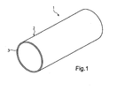
- Fig. 1 shows the basic structure of a stent 1 according to the invention, which has a flexible, tubular body 2 with a wall 3, of which in Fig. 1, the end view is shown.
- the stent according to the present invention may be formed as a balloon expandable or self-expandable stent.
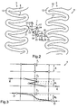
- Fig. 2 the structure of the web structure of the stent according to the invention is shown.
- the wall 3 of the body 2 of the stent 1 has a web structure 4, which can be converted from an unexpanded state into an expanded state.
- the web structure 4 has a multiplicity of adjacent web patterns, of which the web patterns 5 and 6 are shown by way of example in FIG. 2.
- the web patterns 5 and 6 are interconnected by at least one connecting element 7 with each other.
- the webs 8 and 9 and the webs 8 and 9 connecting these webs 12 of the web pattern 5 or the corresponding parts 10, 11 and 13 of the web pattern 6 are identified by reference numerals by way of example.
- the connecting element 7 has three connecting webs 14, 15, 16 arranged at an angle to one another.
- the connecting webs 14 and 15 are connected to each other via a hinge 17 and the connecting webs 15 and 16 via a hinge 18.
- the outer connecting web 15 is also a hinge 19 with a bow 21 and the second outer Connecting web 16 is connected via a hinge 20 with the sheet 22 corresponding to the web structures 5 and 6 respectively.
- the connecting webs 14, 15 and 16 each include right angles between each other.
- the hinges 17, 18, 19 and 20 are formed as film hinges, which are formed by the provision of approximately semi-circular orifices 23, 24, 25 and 26 in the respective connecting webs.
- the width B1 is equal to the width B2 and this in turn equal to the width B3 of the connecting webs 14, 15 and 16.
- the width B2 of the connecting web 15 compared to the width B1 and the width B3 form less.
- FIG. 3 the operation of the connecting element 7 according to the invention within the web structure 4 is illustrated.
- the arrangement 7 1 the formation of the connecting element 7 of FIG. 2 in a schematically simplified representation. It results in a distance A corresponding to the length of the central connecting web 15.
- the state 7 2 of the connecting element 7 illustrates the position of the webs 14, 15 and 16 in a compressed state, which is symbolized by the two arrows K. This results in a distance a1 between the hinges 17 and 18, which is smaller than the distance A.
- FIGS. 4A and 4B in which a section of the web structure 4 is shown in each case in an arrangement in a curved vessel.
- FIG. 4A shows the compressed state of the connecting element 7 with its webs 14 to 16
- FIG. 4B illustrates and illustrates the stretched state of a corresponding connecting element 7 'with its webs 14' to 16 '.
Description
Die Erfindung betrifft einen Stent gemäß dem Oberbegriff des Anspruches 1. Ein derartiger Stand ist aus der WO 99 4992 bekannt.The invention relates to a stent according to the preamble of claim 1. Such a state is known from WO 99 4992.
Aus dem Stand der Technik sind unterschiedlichste Ausgestaltungen von Stents, insbesondere Koronarstents als ballon- oder selbstexpandierbare Stents, vorbekannt. Der Stent bildet eine Gefäßprothese, die aus körperverträglichem Material besteht. Der Stent bzw. die Stentprothese wird dazu verwendet, Blutgefäße oder aber auch andere Körperöffnungen aufzuweiten und im aufgeweiteten Zustand zu halten. Zu diesem Zweck wird der Stent in einem nicht-expandierten Zustand, üblicherweise mit Hilfe eines Ballonkatheters, auf dem der Stent aufgecrimpt ist, im Körper des Patienten positioniert und nachfolgend expandiert. Beim Expandieren werden die einzelnen Stegbereiche des Stents verformt, so dass dieser dauerhaft in der expandierten Form bleibt.A great variety of designs of stents, in particular coronary stents as balloon or self-expandable stents, are previously known from the state of the art. The stent forms a vascular prosthesis, which consists of biocompatible material. The stent or the stent prosthesis is used to dilate blood vessels or other body orifices and hold in the expanded state. For this purpose, the stent is positioned in a non-expanded state, usually by means of a balloon catheter on which the stent is crimped, in the body of the patient and subsequently expanded. During expansion, the individual web areas of the stent are deformed so that it remains permanently in the expanded form.
Ein weiterer Stent der im Oberbegriff des Anspruches 1 angegebenen Art ist beispielsweise aus dem DE-U-297 08 689.8 bekannt. Bei diesem Stent sind als Verbinder zwischen den Stegmustern der Stegstruktur der Stentwand s-förmige Verbindungselemente vorgesehen. Obwohl diese Verbindungselemente im nicht-expandierten Zustand zu einer sehr flexiblen und im expandierten Zustand zu einer Stent-Konstruktion mit hoher Radialkraft bzw. Radialkraft-Aufnahmefähigkeit führen, ergeben sich jedoch Verbesserungsmöglichkeiten dahingehend dass nicht in jedem Falle ausgeschlossen werden kann, dass sich die Verbindungselemente beim Aufweiten aus der Wandebene nach aussen oder innen herauswölben und dadurch das umgebende Gewebe etwas in Mitleidenschaft gezogen wird bzw. die Bildung von Thrombosen oder Restenosen gefördert wird.Another stent specified in the preamble of claim 1 is known for example from DE-U-297 08 689.8. In this stent s-shaped connecting elements are provided as a connector between the web patterns of the web structure of the stent wall. Although these fasteners in the unexpanded state lead to a very flexible and in the expanded state to a stent construction with high radial force or radial force-absorbing capacity, however, there are possibilities for improvement in that it can not be ruled out in all cases that the fasteners during Buckling out of the plane of the wall outward or inward causes the surrounding tissue to be damaged or the formation of thromboses or restenosis is promoted.
Es ist daher Aufgabe der vorliegenden Erfindung, einen Stent der im Oberbegriff des Anspruches 1 angegebenen Art zu schaffen, der im nicht-expandierten Zustand äusserst flexibel ist und bei dem beim Aufweiten verhindert werden kann, dass sich die Verbindungselemente aus der Wandfläche des Stents herausbewegen können.It is therefore an object of the present invention to provide a stent specified in the preamble of claim 1, which is extremely flexible in the unexpanded state and in which can be prevented during expansion that the fasteners can move out of the wall surface of the stent ,
Die Lösung dieser Aufgabe erfolgt durch die Merkmale des Anspruches 1.The solution of this object is achieved by the features of claim 1.
Mit dem erfindungsgemäßen Stent wird eine sehr flexible Struktur beim Biegen und Komprimieren erreicht. Es ist insbesondere vorteilhafterweise möglich zu verhindern, dass beim Aufweiten des Stents die Verbindungselemente das Gewebe im expandierten Zustand des Stents beeinträchtigen, und dass das Lumen des Stentinneren vermindert wird.The stent according to the invention achieves a very flexible structure during bending and compression. In particular, it is advantageously possible to prevent the connecting elements from impairing the tissue in the expanded state of the stent during expansion of the stent, and to reduce the lumen of the stent interior.
Der Grund für diese vorteilhafte Wirkung ist vor allem darin zu sehen, dass sich die Verbindungselemente sowohl beim Biegen (wie zum Beispiel beim Platzieren des Stents in einem gekrümmten Gefäß) und beim Ausdehnen (wie zum Beispiel beim Aufweiten mittels des Ballons) verkürzen, was durch die besondere Anordnung der Verbindungsstege der Verbindungselemente mit den vorgesehenen Scharnieren bzw. Gelenken erreicht wird.The reason for this advantageous effect is mainly to be seen in the fact that shorten the connecting elements both during bending (such as when placing the stent in a curved vessel) and during expansion (such as when expanding by means of the balloon), which the special arrangement of the connecting webs of the connecting elements with the provided hinges or joints is achieved.
Die Unteransprüche haben vorteilhafte Weiterbildungen der Erfindung zum Inhalt.The dependent claims have advantageous developments of the invention to the content.
Die Verbindungsstege der Verbindungselemente sind im nicht-expandierten oder komprimierten Zustand der Stegstruktur zumindest annähernd vorzugsweise exakt im rechten Winkel zueinander angeordnet.In the non-expanded or compressed state of the web structure, the connecting webs of the connecting elements are at least approximately preferably arranged at exactly right angles to one another.
Hierbei ist es möglich, die Breite der Verbindungsstege jeweils gleich zu machen oder, um eine erhöhte Flexibilität zu erreichen, die Breite des mittleren Verbindungssteges etwas geringer auszuführen als die Breite der an den mittleren Steg anschließenden Verbindungsstege.In this case, it is possible to make the width of the connecting webs the same in each case or, in order to achieve increased flexibility, to make the width of the middle connecting web slightly smaller than the width of the connecting webs adjoining the central web.
Die Verbindungsstege, die mit den benachbarten Stegen der Stegstruktur verbunden sind, werden bei einer besonders bevorzugten Ausführungsform ebenfalls über Scharniere angebracht.The connecting webs, which are connected to the adjacent webs of the web structure are mounted in a particularly preferred embodiment also via hinges.
Als besonders bevorzugte und besonders einfache Ausführungsform für die Scharniere sind Filmscharniere vorgesehen.As a particularly preferred and particularly simple embodiment of the hinges film hinges are provided.
Bevorzugterweise besteht der Stent aus einem biokompatiblen Material, das bei einer besonders bevorzugten Ausführungsform eine Nickel-Titan-Legierung oder Edelstahl darstellt.Preferably, the stent is made of a biocompatible material, which in a particularly preferred embodiment is a nickel-titanium alloy or stainless steel.
Weitere Einzelheiten, Merkmale und Vorteile der Erfindung ergeben sich aus nachfolgender Beschreibung anhand der Zeichnung.Further details, features and advantages of the invention will become apparent from the following description with reference to the drawing.
Es zeigt:
- Fig. 1
- eine schematisch stark vereinfachte Prinzipdarstellung der Grundform des erfindungsgemäßen Stents,
- Fig. 2
- eine Darstellung eines Teiles der Stegstruktur der Wand des Stents im nicht-expandierten Zustand,
- Fig. 3
- eine Prinzipdarstellung der erfindungsgemäßen Verbindungselemente zur Erläuterung ihrer Funktionsweise, und
- Fig. 4A, B
- jeweils eine der Fig. 2 entsprechende Darstellung der Anordnung des erfindungsgemäßen Stents in einem gekrümmten Gefäß.
- Fig. 1
- a schematically greatly simplified schematic representation of the basic form of the stent according to the invention,
- Fig. 2
- a representation of a part of the web structure of the wall of the stent in the unexpanded state,
- Fig. 3
- a schematic diagram of the connecting elements according to the invention to explain their operation, and
- Fig. 4A, B
- in each case one of the Fig. 2 corresponding representation of the arrangement of the stent according to the invention in a curved vessel.
Fig. 1 zeigt den grundsätzlichen Aufbau eines erfindungsgemäßen Stents 1, der einen flexiblen, rohrförmigen Körper 2 mit einer Wand 3 aufweist, von der in Fig. 1 die Stirnansicht dargestellt ist. Der Stent gemäß der vorliegenden Erfindung kann als ballonexpandierbarer oder selbstexpandierbarer Stent ausgebildet sein.Fig. 1 shows the basic structure of a stent 1 according to the invention, which has a flexible, tubular body 2 with a wall 3, of which in Fig. 1, the end view is shown. The stent according to the present invention may be formed as a balloon expandable or self-expandable stent.
In Fig. 2 ist der Aufbau der Stegstruktur des erfindungsgemäßen Stents gezeigt.In Fig. 2, the structure of the web structure of the stent according to the invention is shown.
Die Wand 3 des Körpers 2 des Stents 1 weist eine Stegstruktur 4 auf, die von einem nicht-expandierten Zustand in einen expandierten Zustand überführbar ist.The wall 3 of the body 2 of the stent 1 has a
Hierbei weist die Stegstruktur 4 eine Vielzahl von benachbarten Stegmustern auf, von denen in Fig. 2 beispielhaft die Stegmuster 5 und 6 dargestellt sind. Die Stegmuster 5 und 6 sind untereinander durch zumindestens ein Verbindungselement 7 miteinander verbunden.In this case, the
Zur Verdeutlichung des Aufbaus der Stegmuster 5 und 6 sind beispielhaft die Stege 8 und 9 sowie der diese Stege 8 und 9 verbindende Bogen 12 des Stegmusters 5 bzw. die entsprechenden Teile 10, 11 und 13 des Stegmusters 6 mit Bezugsziffern identifiziert.To illustrate the structure of the
Das Verbindungselement 7 weist drei im Winkel zueinander angeordnete Verbindungsstege 14, 15, 16 auf. Die Verbindungsstege 14 und 15 sind hierbei über ein Scharnier 17 und die Verbindungsstege 15 und 16 über ein Scharnier 18 miteinander verbunden. Der äussere Verbindungssteg 15 ist ferner über ein Scharnier 19 mit einem Bogen 21 und der zweite äussere Verbindungssteg 16 über ein Scharnier 20 mit dem Bogen 22 entsprechend der Stegstrukturen 5 bzw. 6 verbunden.The connecting element 7 has three connecting
Bei der in Fig. 2 besonders bevorzugten Ausführungsform schließen die Verbindungsstege 14, 15 und 16 jeweils rechte Winkel zwischeneinander ein. Die Scharniere 17, 18, 19 und 20 sind als Filmscharniere ausgebildet, die durch das Vorsehen von annähernd halbkreisförmigen Ausmündungen 23, 24, 25 bzw. 26 in den jeweiligen Verbindungsstegen gebildet werden.In the particularly preferred embodiment in FIG. 2, the connecting
Ferner ist bei der in Fig. 2 dargestellten besonders bevorzugten Ausführungsform die Breite B1 gleich der Breite B2 und diese wiederum gleich der Breite B3 der Verbindungsstege 14, 15 bzw. 16. Zur Erhöhung der Flexibilität ist es jedoch möglich, insbesondere die Breite B2 des Verbindungssteges 15 im Vergleich zur Breite B1 und zur Breite B3 geringer auszubilden.Further, in the particularly preferred embodiment shown in Fig. 2, the width B1 is equal to the width B2 and this in turn equal to the width B3 of the connecting
In Fig. 3 ist die Wirkungsweise des erfindungsgemäßen Verbindungselementes 7 innerhalb der Stegstruktur 4 verdeutlicht. Hierbei stellt die Anordnung 71 die Ausbildung des Verbindungselementes 7 gemäß Fig. 2 in schematisch vereinfachter Darstellung dar. Es ergibt sich ein Abstand A der der Länge des mittleren Verbindungssteges 15 entspricht.In Fig. 3, the operation of the connecting element 7 according to the invention within the
Der Zustand 72 des Verbindungselementes 7 verdeutlicht die Stellung der Stege 14, 15 und 16 in einem komprimierten Zustand, der durch die beiden Pfeile K symbolisiert wird. Hierbei ergibt sich ein Abstand a1 zwischen den Scharnieren 17 und 18, der kleiner dem Abstand A ist.The state 7 2 of the connecting element 7 illustrates the position of the
Auch bei dem Zustand 73, der einem expandierten Zustand entspricht, ergibt sich ein Abstand a2, der ebenfalls kleiner ist als der Abstand A.Even in the state 7 3 , which corresponds to an expanded state, there is a distance a 2 , which is also smaller than the distance A.
Dies bedeutet, dass sich eine Verkürzung des Verbindungselementes 7 sowohl im komprimierten wie auch im expandierten Zustand ergibt, der es verhindert, dass die Verbindungselemente 7 aus der Wandebene der Stegstruktur 4 heraus vortreten, so dass insbesondere im implantierten Zustand eine Verletzung des umgebenden Gewebes des jeweiligen Volumens vermieden werden kann. Ferner ergibt sich der Vorteil, dass die Verbindungselemente in gekrümmten Gefässen eine gleichmäßige Wandabdeckung durch die Stegmuster und Flexibilität der gesamten Stentkonstruktion ergeben.This means that a shortening of the connecting element 7 both in the compressed as well as in the expanded Condition results, which prevents the connecting elements 7 from protruding out of the wall level of the
Hierzu ist auf die Figur 4A und 4B zu verweisen, in der ein Ausschnitt der Stegstruktur 4 jeweils bei einer Anordnung in einem gekrümmten Gefäß dargestellt ist.For this, reference is made to FIGS. 4A and 4B, in which a section of the
Figur 4A zeigt hierbei den gestauchten Zustand des Verbindungselementes 7 mit seinen Stegen 14 bis 16, während 4B den gestreckten Zustand eines entsprechenden Verbindungselementes 7' mit seinen Stegen 14' bis 16' illustriert und verdeutlicht. FIG. 4A shows the compressed state of the connecting element 7 with its
Claims (10)
- Stent (1)- comprising a tubular flexible body (2), the wall (3) of which has a web structure (4) which can be transformed from a non-expanded state to an expanded state,- the web structure (4) having a plurality of adjacent web patterns (5, 9) having webs (8, 9 and 10, 11 respectively) arranged side by side, and- at least one pair of the web patterns (5, 6) being connected together by means of at least one connecting element (7),characterised in that- the connecting element (7) has three connecting webs (14, 15, 16) having associated web widths (B1, B2, B3) arranged at an angle relative to one another and connected together by means of hinges (17, 18) the width of which is smaller than at least one of the web widths (B1, B2, B3) of the connecting webs (14, 15, 16).
- Stent according to claim 1, characterised in that the connecting webs (14-16) are arranged at least approximately at a right angle to one another in the non-expanded or compressed state of the web structure (4).
- Stent according to claim 1 or claim 2, characterised in that the connecting webs (14-16) all have the same width (B1, B2, B3).
- Stent according to claim 1 or claim 2, characterised in that the connecting webs (14, 15, 16) have different widths.
- Stent according to claim 1 or claim 2, characterised in that the width (B2) of the central connecting web (15) is smaller than the width (B1 or B3) of the outer connecting webs (14, 16).
- Stent according to one of claims 1 to 5, characterised in that the outer connecting webs (14, 16) are each connected to the adjacent web (21, 22) of the wall structure (4) by means of a hinge (19, 20).
- Stent according to one of claims 1 to 6, characterised in that the hinges (17-20) are designed as film hinges.
- Stent according to one of claims 1 to 7, characterised in that the material of the wall (3) of the body (2) consists of biocompatible material.
- Stent according to claim 8, characterised in that the web structure (4) and the connecting elements (7) consist of a nickel-titanium alloy, plastic or stainless steel.
- Stent according to one of claims 1 to 9, characterised in that the lengths of the connecting webs (14-16) are identical or different.
Applications Claiming Priority (1)
| Application Number | Priority Date | Filing Date | Title |
|---|---|---|---|
| EP01122285A EP1293177B1 (en) | 2001-09-18 | 2001-09-18 | Stent |
Related Parent Applications (1)
| Application Number | Title | Priority Date | Filing Date |
|---|---|---|---|
| EP01122285A Division EP1293177B1 (en) | 2001-09-18 | 2001-09-18 | Stent |
Publications (2)
| Publication Number | Publication Date |
|---|---|
| EP1516600A1 EP1516600A1 (en) | 2005-03-23 |
| EP1516600B1 true EP1516600B1 (en) | 2007-03-14 |
Family
ID=8178653
Family Applications (2)
| Application Number | Title | Priority Date | Filing Date |
|---|---|---|---|
| EP04030668A Expired - Lifetime EP1516600B1 (en) | 2001-09-18 | 2001-09-18 | Stent |
| EP01122285A Expired - Lifetime EP1293177B1 (en) | 2001-09-18 | 2001-09-18 | Stent |
Family Applications After (1)
| Application Number | Title | Priority Date | Filing Date |
|---|---|---|---|
| EP01122285A Expired - Lifetime EP1293177B1 (en) | 2001-09-18 | 2001-09-18 | Stent |
Country Status (3)
| Country | Link |
|---|---|
| US (3) | US20030055487A1 (en) |
| EP (2) | EP1516600B1 (en) |
| DE (2) | DE50105476D1 (en) |
Cited By (10)
| Publication number | Priority date | Publication date | Assignee | Title |
|---|---|---|---|---|
| JP2007125394A (en) * | 2005-11-03 | 2007-05-24 | Cordis Corp | Intraluminal medical device with strain concentrating bridge |
| US7789905B2 (en) | 1998-09-05 | 2010-09-07 | Abbottt Laboratories Vascular Enterprises Limited | Apparatus for a stent having an expandable web structure |
| US7811314B2 (en) | 1998-09-05 | 2010-10-12 | Abbott Laboratories Vascular Enterprises Limited | Methods and apparatus for stenting comprising enhanced embolic protection coupled with improved protections against restenosis and thrombus formation |
| US7815763B2 (en) | 2001-09-28 | 2010-10-19 | Abbott Laboratories Vascular Enterprises Limited | Porous membranes for medical implants and methods of manufacture |
| US7850726B2 (en) | 2007-12-20 | 2010-12-14 | Abbott Laboratories Vascular Enterprises Limited | Endoprosthesis having struts linked by foot extensions |
| US7887578B2 (en) | 1998-09-05 | 2011-02-15 | Abbott Laboratories Vascular Enterprises Limited | Stent having an expandable web structure |
| US8016874B2 (en) | 2007-05-23 | 2011-09-13 | Abbott Laboratories Vascular Enterprises Limited | Flexible stent with elevated scaffolding properties |
| US8128679B2 (en) | 2007-05-23 | 2012-03-06 | Abbott Laboratories Vascular Enterprises Limited | Flexible stent with torque-absorbing connectors |
| US8337544B2 (en) | 2007-12-20 | 2012-12-25 | Abbott Laboratories Vascular Enterprises Limited | Endoprosthesis having flexible connectors |
| US8920488B2 (en) | 2007-12-20 | 2014-12-30 | Abbott Laboratories Vascular Enterprises Limited | Endoprosthesis having a stable architecture |
Families Citing this family (35)
| Publication number | Priority date | Publication date | Assignee | Title |
|---|---|---|---|---|
| US20020019660A1 (en) * | 1998-09-05 | 2002-02-14 | Marc Gianotti | Methods and apparatus for a curved stent |
| US6290673B1 (en) | 1999-05-20 | 2001-09-18 | Conor Medsystems, Inc. | Expandable medical device delivery system and method |
| US6764507B2 (en) * | 2000-10-16 | 2004-07-20 | Conor Medsystems, Inc. | Expandable medical device with improved spatial distribution |
| PT1328213E (en) * | 2000-10-16 | 2005-10-31 | Conor Medsystems Inc | EXPANSIVE MEDICAL DEVICE FOR THE ADMINISTRATION OF A BENEFICIAL AGENT |
| US7842083B2 (en) | 2001-08-20 | 2010-11-30 | Innovational Holdings, Llc. | Expandable medical device with improved spatial distribution |
| EP1516600B1 (en) * | 2001-09-18 | 2007-03-14 | Abbott Laboratories Vascular Enterprises Limited | Stent |
| JP3660650B2 (en) * | 2002-06-13 | 2005-06-15 | 株式会社東芝 | Manufacturing method of semiconductor device |
| AU2003231910A1 (en) * | 2002-06-13 | 2003-12-31 | Existent, Inc. | Mechanical structures and implants using said structures |
| US8277223B2 (en) | 2004-02-10 | 2012-10-02 | Koninklijke Philips Electronics N.V. | External defibrillator training apparatus and method |
| DE102004022044B4 (en) * | 2004-05-03 | 2008-12-18 | Qualimed Innovative Medizinprodukte Gmbh | stent |
| US7763065B2 (en) | 2004-07-21 | 2010-07-27 | Reva Medical, Inc. | Balloon expandable crush-recoverable stent device |
| EP1799151A4 (en) * | 2004-09-15 | 2014-09-17 | Conor Medsystems Inc | Bifurcation stent with crushable end and method for delivery of a stent to a bifurcation |
| US8292944B2 (en) | 2004-12-17 | 2012-10-23 | Reva Medical, Inc. | Slide-and-lock stent |
| US7914574B2 (en) | 2005-08-02 | 2011-03-29 | Reva Medical, Inc. | Axially nested slide and lock expandable device |
| US9149378B2 (en) | 2005-08-02 | 2015-10-06 | Reva Medical, Inc. | Axially nested slide and lock expandable device |
| US20070173925A1 (en) * | 2006-01-25 | 2007-07-26 | Cornova, Inc. | Flexible expandable stent |
| US7704275B2 (en) | 2007-01-26 | 2010-04-27 | Reva Medical, Inc. | Circumferentially nested expandable device |
| JP5216098B2 (en) | 2007-11-30 | 2013-06-19 | レヴァ メディカル、 インコーポレイテッド | Axial and radially nested expandable device |
| WO2009080327A2 (en) * | 2007-12-20 | 2009-07-02 | Abbott Laboratories Vascular Enterprises Limited | Endoprosthesis having a stable architecture and endoprosthesis having flexible connectors |
| US7947071B2 (en) * | 2008-10-10 | 2011-05-24 | Reva Medical, Inc. | Expandable slide and lock stent |
| JP4852631B2 (en) * | 2009-06-28 | 2012-01-11 | 株式会社沖データ | Communication device and connection control method thereof |
| EP2496189A4 (en) | 2009-11-04 | 2016-05-11 | Nitinol Devices And Components Inc | Alternating circumferential bridge stent design and methods for use thereof |
| JP5809237B2 (en) | 2010-04-10 | 2015-11-10 | レヴァ メディカル、 インコーポレイテッドReva Medical, Inc. | Expandable slide lock stent |
| US8882824B2 (en) * | 2010-04-20 | 2014-11-11 | Cg Bio Co., Ltd. | Expanding vascular stent |
| US8864811B2 (en) | 2010-06-08 | 2014-10-21 | Veniti, Inc. | Bi-directional stent delivery system |
| US9301864B2 (en) | 2010-06-08 | 2016-04-05 | Veniti, Inc. | Bi-directional stent delivery system |
| US9233014B2 (en) | 2010-09-24 | 2016-01-12 | Veniti, Inc. | Stent with support braces |
| EP2624791B1 (en) | 2010-10-08 | 2017-06-21 | Confluent Medical Technologies, Inc. | Alternating circumferential bridge stent design |
| CA2873440C (en) | 2012-05-14 | 2020-06-02 | C.R. Bard, Inc. | Uniformly expandable stent |
| US20140094900A1 (en) * | 2012-10-01 | 2014-04-03 | Brigham Young University | Compliant biocompatible device and method of manufacture |
| USD723165S1 (en) | 2013-03-12 | 2015-02-24 | C. R. Bard, Inc. | Stent |
| WO2014159337A1 (en) | 2013-03-14 | 2014-10-02 | Reva Medical, Inc. | Reduced - profile slide and lock stent |
| DE102013104550B4 (en) | 2013-05-03 | 2021-07-01 | Acandis Gmbh | Medical device for insertion into a hollow organ in the body |
| WO2015007435A1 (en) * | 2013-07-19 | 2015-01-22 | Biotronik Ag | Stent |
| US10849769B2 (en) * | 2017-08-23 | 2020-12-01 | Vesper Medical, Inc. | Non-foreshortening stent |
Family Cites Families (118)
| Publication number | Priority date | Publication date | Assignee | Title |
|---|---|---|---|---|
| US4580568A (en) * | 1984-10-01 | 1986-04-08 | Cook, Incorporated | Percutaneous endovascular stent and method for insertion thereof |
| US5102417A (en) * | 1985-11-07 | 1992-04-07 | Expandable Grafts Partnership | Expandable intraluminal graft, and method and apparatus for implanting an expandable intraluminal graft |
| US4738740A (en) * | 1985-11-21 | 1988-04-19 | Corvita Corporation | Method of forming implantable vascular grafts |
| US4743252A (en) * | 1986-01-13 | 1988-05-10 | Corvita Corporation | Composite grafts |
| US4800882A (en) * | 1987-03-13 | 1989-01-31 | Cook Incorporated | Endovascular stent and delivery system |
| US4907336A (en) * | 1987-03-13 | 1990-03-13 | Cook Incorporated | Method of making an endovascular stent and delivery system |
| US5019090A (en) * | 1988-09-01 | 1991-05-28 | Corvita Corporation | Radially expandable endoprosthesis and the like |
| US5015253A (en) * | 1989-06-15 | 1991-05-14 | Cordis Corporation | Non-woven endoprosthesis |
| US5292331A (en) * | 1989-08-24 | 1994-03-08 | Applied Vascular Engineering, Inc. | Endovascular support device |
| CA2026604A1 (en) * | 1989-10-02 | 1991-04-03 | Rodney G. Wolff | Articulated stent |
| US5221261A (en) * | 1990-04-12 | 1993-06-22 | Schneider (Usa) Inc. | Radially expandable fixation member |
| US5116360A (en) * | 1990-12-27 | 1992-05-26 | Corvita Corporation | Mesh composite graft |
| CA2380683C (en) * | 1991-10-28 | 2006-08-08 | Advanced Cardiovascular Systems, Inc. | Expandable stents and method for making same |
| US5282823A (en) * | 1992-03-19 | 1994-02-01 | Medtronic, Inc. | Intravascular radially expandable stent |
| US5591224A (en) * | 1992-03-19 | 1997-01-07 | Medtronic, Inc. | Bioelastomeric stent |
| BE1006440A3 (en) * | 1992-12-21 | 1994-08-30 | Dereume Jean Pierre Georges Em | Luminal endoprosthesis AND METHOD OF PREPARATION. |
| DE4303181A1 (en) * | 1993-02-04 | 1994-08-11 | Angiomed Ag | Implantable catheter |
| ATE178218T1 (en) * | 1993-02-05 | 1999-04-15 | Joe W And Dorothy Dorsett Brow | ULTRASONIC BALLOON CATHETER FOR ANGIOPLASTY |
| US5735892A (en) * | 1993-08-18 | 1998-04-07 | W. L. Gore & Associates, Inc. | Intraluminal stent graft |
| US5380299A (en) * | 1993-08-30 | 1995-01-10 | Med Institute, Inc. | Thrombolytic treated intravascular medical device |
| AU8012394A (en) * | 1993-10-01 | 1995-05-01 | Emory University | Self-expanding intraluminal composite prosthesis |
| WO1995010989A1 (en) * | 1993-10-19 | 1995-04-27 | Scimed Life Systems, Inc. | Intravascular stent pump |
| US5723004A (en) * | 1993-10-21 | 1998-03-03 | Corvita Corporation | Expandable supportive endoluminal grafts |
| US5855598A (en) * | 1993-10-21 | 1999-01-05 | Corvita Corporation | Expandable supportive branched endoluminal grafts |
| US5733303A (en) * | 1994-03-17 | 1998-03-31 | Medinol Ltd. | Flexible expandable stent |
| US5449373A (en) * | 1994-03-17 | 1995-09-12 | Medinol Ltd. | Articulated stent |
| US6461381B2 (en) * | 1994-03-17 | 2002-10-08 | Medinol, Ltd. | Flexible expandable stent |
| DE4418336A1 (en) * | 1994-05-26 | 1995-11-30 | Angiomed Ag | Stent for widening and holding open receptacles |
| US5743874A (en) * | 1994-08-29 | 1998-04-28 | Fischell; Robert E. | Integrated catheter for balloon angioplasty and stent delivery |
| US5723003A (en) * | 1994-09-13 | 1998-03-03 | Ultrasonic Sensing And Monitoring Systems | Expandable graft assembly and method of use |
| US5630829A (en) * | 1994-12-09 | 1997-05-20 | Intervascular, Inc. | High hoop strength intraluminal stent |
| ATE220308T1 (en) * | 1995-03-01 | 2002-07-15 | Scimed Life Systems Inc | LONGITUDONLY FLEXIBLE AND EXPANDABLE STENT |
| US7204848B1 (en) * | 1995-03-01 | 2007-04-17 | Boston Scientific Scimed, Inc. | Longitudinally flexible expandable stent |
| US5591197A (en) * | 1995-03-14 | 1997-01-07 | Advanced Cardiovascular Systems, Inc. | Expandable stent forming projecting barbs and method for deploying |
| US5709713A (en) * | 1995-03-31 | 1998-01-20 | Cardiovascular Concepts, Inc. | Radially expansible vascular prosthesis having reversible and other locking structures |
| ATE169484T1 (en) * | 1995-04-01 | 1998-08-15 | Variomed Ag | STENT FOR TRANSLUMINAL IMPLANTATION IN HOLLOW ORGANS |
| US5593442A (en) * | 1995-06-05 | 1997-01-14 | Localmed, Inc. | Radially expansible and articulated vessel scaffold |
| US6602281B1 (en) * | 1995-06-05 | 2003-08-05 | Avantec Vascular Corporation | Radially expansible vessel scaffold having beams and expansion joints |
| EP0830108B1 (en) * | 1995-06-08 | 2003-09-17 | Ave Galway Limited | Endovascular stent |
| US6261318B1 (en) * | 1995-07-25 | 2001-07-17 | Medstent Inc. | Expandable stent |
| CN1208101C (en) * | 1995-07-25 | 2005-06-29 | 梅德斯坦特有限公司 | Expansible stent |
| ES2131253T3 (en) * | 1995-11-14 | 1999-07-16 | Schneider Europ Gmbh | DEVICE FOR THE IMPLEMENTATION OF AN ENDOPROTESIS. |
| US5593417A (en) * | 1995-11-27 | 1997-01-14 | Rhodes; Valentine J. | Intravascular stent with secure mounting means |
| US6203569B1 (en) * | 1996-01-04 | 2001-03-20 | Bandula Wijay | Flexible stent |
| US5895406A (en) * | 1996-01-26 | 1999-04-20 | Cordis Corporation | Axially flexible stent |
| US5738817A (en) * | 1996-02-08 | 1998-04-14 | Rutgers, The State University | Solid freeform fabrication methods |
| DE19614160A1 (en) * | 1996-04-10 | 1997-10-16 | Variomed Ag | Stent for transluminal implantation in hollow organs |
| NZ331269A (en) * | 1996-04-10 | 2000-01-28 | Advanced Cardiovascular System | Expandable stent, its structural strength varying along its length |
| US6235053B1 (en) | 1998-02-02 | 2001-05-22 | G. David Jang | Tubular stent consists of chevron-shape expansion struts and contralaterally attached diagonal connectors |
| US5922021A (en) * | 1996-04-26 | 1999-07-13 | Jang; G. David | Intravascular stent |
| US5954743A (en) * | 1996-04-26 | 1999-09-21 | Jang; G. David | Intravascular stent |
| US6039756A (en) * | 1996-04-26 | 2000-03-21 | Jang; G. David | Intravascular stent |
| JP4636634B2 (en) * | 1996-04-26 | 2011-02-23 | ボストン サイエンティフィック サイムド,インコーポレイテッド | Intravascular stent |
| FR2750853B1 (en) * | 1996-07-10 | 1998-12-18 | Braun Celsa Sa | MEDICAL PROSTHESIS, IN PARTICULAR FOR ANEVRISMS, WITH PERFECTIONED CONNECTION BETWEEN ITS SHEATH AND ITS STRUCTURE |
| US6174326B1 (en) * | 1996-09-25 | 2001-01-16 | Terumo Kabushiki Kaisha | Radiopaque, antithrombogenic stent and method for its production |
| US5868781A (en) * | 1996-10-22 | 1999-02-09 | Scimed Life Systems, Inc. | Locking stent |
| US5827321A (en) * | 1997-02-07 | 1998-10-27 | Cornerstone Devices, Inc. | Non-Foreshortening intraluminal prosthesis |
| DE29702671U1 (en) * | 1997-02-17 | 1997-04-10 | Jomed Implantate Gmbh | Stent |
| GB2323034B (en) * | 1997-03-13 | 2001-07-25 | Zimmer Ltd | Prosthesis for knee replacement |
| US5810872A (en) * | 1997-03-14 | 1998-09-22 | Kanesaka; Nozomu | Flexible stent |
| US5853419A (en) * | 1997-03-17 | 1998-12-29 | Surface Genesis, Inc. | Stent |
| US6200335B1 (en) * | 1997-03-31 | 2001-03-13 | Kabushikikaisha Igaki Iryo Sekkei | Stent for vessel |
| US6033433A (en) * | 1997-04-25 | 2000-03-07 | Scimed Life Systems, Inc. | Stent configurations including spirals |
| US5741327A (en) * | 1997-05-06 | 1998-04-21 | Global Therapeutics, Inc. | Surgical stent featuring radiopaque markers |
| US5876450A (en) * | 1997-05-09 | 1999-03-02 | Johlin, Jr.; Frederick C. | Stent for draining the pancreatic and biliary ducts and instrumentation for the placement thereof |
| DE29708689U1 (en) * | 1997-05-15 | 1997-07-17 | Jomed Implantate Gmbh | Coronary stent |
| DE29708803U1 (en) * | 1997-05-17 | 1997-07-31 | Jomed Implantate Gmbh | Radially expandable stent for implantation in a body vessel in the area of a vascular branch |
| DE29708879U1 (en) * | 1997-05-20 | 1997-07-31 | Jomed Implantate Gmbh | Coronary stent |
| US7329277B2 (en) * | 1997-06-13 | 2008-02-12 | Orbusneich Medical, Inc. | Stent having helical elements |
| EP0888757B1 (en) * | 1997-06-30 | 2004-01-21 | Medex Holding GmbH | Intraluminal implant |
| US5855600A (en) * | 1997-08-01 | 1999-01-05 | Inflow Dynamics Inc. | Flexible implantable stent with composite design |
| US5948016A (en) * | 1997-09-25 | 1999-09-07 | Jang; G. David | Intravascular stent with non-parallel slots |
| US6033435A (en) * | 1997-11-03 | 2000-03-07 | Divysio Solutions Ulc | Bifurcated stent and method for the manufacture and delivery of same |
| AU2579999A (en) * | 1998-02-03 | 1999-08-16 | Cardiovascular Interventional Systems, Inc. | Tubular stent consists of non-parallel expansion struts and contralaterally attached diagonal connectors |
| US6113627A (en) * | 1998-02-03 | 2000-09-05 | Jang; G. David | Tubular stent consists of horizontal expansion struts and contralaterally attached diagonal-connectors |
| AU2684499A (en) * | 1998-02-17 | 1999-08-30 | G. David Jang | Tubular stent consists of chevron-shape expansion struts and ipsilaterally attached m-frame connectors |
| JP4351388B2 (en) * | 1998-03-04 | 2009-10-28 | ボストン サイエンティフィック リミテッド | Improved stent cell structure |
| US6179868B1 (en) * | 1998-03-27 | 2001-01-30 | Janet Burpee | Stent with reduced shortening |
| US6241762B1 (en) * | 1998-03-30 | 2001-06-05 | Conor Medsystems, Inc. | Expandable medical device with ductile hinges |
| US6019789A (en) * | 1998-04-01 | 2000-02-01 | Quanam Medical Corporation | Expandable unit cell and intraluminal stent |
| US6261319B1 (en) * | 1998-07-08 | 2001-07-17 | Scimed Life Systems, Inc. | Stent |
| US20020019660A1 (en) * | 1998-09-05 | 2002-02-14 | Marc Gianotti | Methods and apparatus for a curved stent |
| US6682554B2 (en) * | 1998-09-05 | 2004-01-27 | Jomed Gmbh | Methods and apparatus for a stent having an expandable web structure |
| US6193744B1 (en) * | 1998-09-10 | 2001-02-27 | Scimed Life Systems, Inc. | Stent configurations |
| US6042597A (en) * | 1998-10-23 | 2000-03-28 | Scimed Life Systems, Inc. | Helical stent design |
| US6168409B1 (en) * | 1998-11-13 | 2001-01-02 | Rosaldo Fare | Apparatus for making two component fibers or continuous filaments using flexible tube inserts |
| US6190403B1 (en) * | 1998-11-13 | 2001-02-20 | Cordis Corporation | Low profile radiopaque stent with increased longitudinal flexibility and radial rigidity |
| US6340366B2 (en) * | 1998-12-08 | 2002-01-22 | Bandula Wijay | Stent with nested or overlapping rings |
| US6730116B1 (en) * | 1999-04-16 | 2004-05-04 | Medtronic, Inc. | Medical device for intraluminal endovascular stenting |
| US6245101B1 (en) * | 1999-05-03 | 2001-06-12 | William J. Drasler | Intravascular hinge stent |
| US20010047200A1 (en) * | 1999-10-13 | 2001-11-29 | Raymond Sun | Non-foreshortening intraluminal prosthesis |
| US6312463B1 (en) * | 2000-02-01 | 2001-11-06 | Endotex Interventional Systems, Inc. | Micro-porous mesh stent with hybrid structure |
| US6723119B2 (en) * | 2000-03-01 | 2004-04-20 | Medinol Ltd. | Longitudinally flexible stent |
| US6602282B1 (en) * | 2000-05-04 | 2003-08-05 | Avantec Vascular Corporation | Flexible stent structure |
| US7070614B1 (en) * | 2000-05-22 | 2006-07-04 | Malte Neuss | Radially expandable vessel support |
| US8034097B2 (en) * | 2000-05-22 | 2011-10-11 | Malte Neuss | Radially expandable vessel support |
| US6377835B1 (en) * | 2000-08-30 | 2002-04-23 | Siemens Aktiengesellschaft | Method for separating arteries and veins in 3D MR angiographic images using correlation analysis |
| US7766956B2 (en) * | 2000-09-22 | 2010-08-03 | Boston Scientific Scimed, Inc. | Intravascular stent and assembly |
| EP1309293B1 (en) * | 2000-09-22 | 2006-08-23 | Boston Scientific Scimed, Inc. | Intravascular stent apparatus |
| US6506211B1 (en) * | 2000-11-13 | 2003-01-14 | Scimed Life Systems, Inc. | Stent designs |
| US6540776B2 (en) * | 2000-12-28 | 2003-04-01 | Advanced Cardiovascular Systems, Inc. | Sheath for a prosthesis and methods of forming the same |
| US6679911B2 (en) * | 2001-03-01 | 2004-01-20 | Cordis Corporation | Flexible stent |
| US6998060B2 (en) * | 2001-03-01 | 2006-02-14 | Cordis Corporation | Flexible stent and method of manufacture |
| US6790227B2 (en) * | 2001-03-01 | 2004-09-14 | Cordis Corporation | Flexible stent |
| US6503272B2 (en) * | 2001-03-21 | 2003-01-07 | Cordis Corporation | Stent-based venous valves |
| US7520892B1 (en) * | 2001-06-28 | 2009-04-21 | Advanced Cardiovascular Systems, Inc. | Low profile stent with flexible link |
| EP1516600B1 (en) * | 2001-09-18 | 2007-03-14 | Abbott Laboratories Vascular Enterprises Limited | Stent |
| US7029493B2 (en) * | 2002-01-25 | 2006-04-18 | Cordis Corporation | Stent with enhanced crossability |
| US20040051201A1 (en) * | 2002-04-11 | 2004-03-18 | Greenhalgh Skott E. | Coated stent and method for coating by treating an electrospun covering with heat or chemicals |
| WO2003094798A1 (en) * | 2002-05-08 | 2003-11-20 | Abbott Laboratories | Endoprosthesis having foot extensions |
| US8080052B2 (en) * | 2002-06-28 | 2011-12-20 | Cordis Corporation | Stent with diagonal flexible connecting links |
| US7025777B2 (en) * | 2002-07-31 | 2006-04-11 | Unison Therapeutics, Inc. | Flexible and conformable stent and method of forming same |
| US7179286B2 (en) * | 2003-02-21 | 2007-02-20 | Boston Scientific Scimed, Inc. | Stent with stepped connectors |
| US7625401B2 (en) * | 2003-05-06 | 2009-12-01 | Abbott Laboratories | Endoprosthesis having foot extensions |
| US6846323B2 (en) * | 2003-05-15 | 2005-01-25 | Advanced Cardiovascular Systems, Inc. | Intravascular stent |
| EP1895938B1 (en) * | 2005-06-30 | 2019-02-20 | Abbott Laboratories | Endoprosthesis having foot extensions |
| US20080077231A1 (en) * | 2006-07-06 | 2008-03-27 | Prescient Medical, Inc. | Expandable vascular endoluminal prostheses |
| FR2911063B1 (en) * | 2007-01-09 | 2009-03-20 | Stentys S A S Soc Par Actions | RUPTIBLE BRIDGE STRUCTURE FOR STENT, AND STENT INCLUDING SUCH BRIDGE STRUCTURES. |
-
2001
- 2001-09-18 EP EP04030668A patent/EP1516600B1/en not_active Expired - Lifetime
- 2001-09-18 DE DE50105476T patent/DE50105476D1/en not_active Expired - Lifetime
- 2001-09-18 DE DE50112209T patent/DE50112209D1/en not_active Expired - Lifetime
- 2001-09-18 EP EP01122285A patent/EP1293177B1/en not_active Expired - Lifetime
-
2002
- 2002-09-12 US US10/241,523 patent/US20030055487A1/en not_active Abandoned
-
2006
- 2006-05-16 US US11/435,260 patent/US7611531B2/en not_active Expired - Fee Related
-
2009
- 2009-10-29 US US12/608,335 patent/US20100114297A1/en not_active Abandoned
Cited By (26)
| Publication number | Priority date | Publication date | Assignee | Title |
|---|---|---|---|---|
| US7887577B2 (en) | 1998-09-05 | 2011-02-15 | Abbott Laboratories Vascular Enterprises Limited | Apparatus for a stent having an expandable web structure |
| US7789904B2 (en) | 1998-09-05 | 2010-09-07 | Abbott Laboratories Vascular Enterprises Limited | Methods and apparatus for a stent having an expandable web structure |
| US7927364B2 (en) | 1998-09-05 | 2011-04-19 | Abbott Laboratories Vascular Enterprises Limited | Methods and apparatus for stenting comprising enhanced embolic protection coupled with improved protections against restenosis and thrombus formation |
| US7927365B2 (en) | 1998-09-05 | 2011-04-19 | Abbott Laboratories Vascular Enterprises Limited | Methods and apparatus for stenting comprising enhanced embolic protection coupled with improved protections against restenosis and thrombus formation |
| US7811314B2 (en) | 1998-09-05 | 2010-10-12 | Abbott Laboratories Vascular Enterprises Limited | Methods and apparatus for stenting comprising enhanced embolic protection coupled with improved protections against restenosis and thrombus formation |
| US8814926B2 (en) | 1998-09-05 | 2014-08-26 | Abbott Laboratories Vascular Enterprises Limited | Methods and apparatus for stenting comprising enhanced embolic protection coupled with improved protections against restenosis and thrombus formation |
| US7815672B2 (en) | 1998-09-05 | 2010-10-19 | Abbott Laboratories Vascular Enterprises Limited | Apparatus for a stent having an expandable web structure |
| US7842079B2 (en) | 1998-09-05 | 2010-11-30 | Abbott Laboratories Vascular Enterprises Limited | Apparatus for a stent having an expandable web structure and delivery system |
| US7842078B2 (en) | 1998-09-05 | 2010-11-30 | Abbott Laboratories Vascular Enterprises Limited | Apparatus for a stent having an expandable web structure and delivery system |
| US7846196B2 (en) | 1998-09-05 | 2010-12-07 | Abbott Laboratories Vascular Enterprises Limited | Apparatus for a stent having an expandable web structure |
| US8343208B2 (en) | 1998-09-05 | 2013-01-01 | Abbott Laboratories Vascular Enterprises Limited | Stent having an expandable web structure |
| US7887578B2 (en) | 1998-09-05 | 2011-02-15 | Abbott Laboratories Vascular Enterprises Limited | Stent having an expandable web structure |
| US9517146B2 (en) | 1998-09-05 | 2016-12-13 | Abbott Laboratories Vascular Enterprises Limited | Methods and apparatus for stenting comprising enhanced embolic protection coupled with improved protections against restenosis and thrombus formation |
| US7789905B2 (en) | 1998-09-05 | 2010-09-07 | Abbottt Laboratories Vascular Enterprises Limited | Apparatus for a stent having an expandable web structure |
| US7794491B2 (en) | 1998-09-05 | 2010-09-14 | Abbott Laboratories Vascular Enterprises Limited | Apparatus for a stent having an expandable web structure and delivery system |
| US8303645B2 (en) | 1998-09-05 | 2012-11-06 | Abbott Laboratories Vascular Enterprises Limited | Methods and apparatus for a stent having an expandable web structure |
| US8088157B2 (en) | 1998-09-05 | 2012-01-03 | Abbott Laboratories Vascular Enterprises Limited | Methods and apparatus for stenting comprising enhanced embolic protection coupled with improved protections against restenosis and thrombus formation |
| US7815763B2 (en) | 2001-09-28 | 2010-10-19 | Abbott Laboratories Vascular Enterprises Limited | Porous membranes for medical implants and methods of manufacture |
| JP2007125394A (en) * | 2005-11-03 | 2007-05-24 | Cordis Corp | Intraluminal medical device with strain concentrating bridge |
| US8128679B2 (en) | 2007-05-23 | 2012-03-06 | Abbott Laboratories Vascular Enterprises Limited | Flexible stent with torque-absorbing connectors |
| US8016874B2 (en) | 2007-05-23 | 2011-09-13 | Abbott Laboratories Vascular Enterprises Limited | Flexible stent with elevated scaffolding properties |
| US9320627B2 (en) | 2007-05-23 | 2016-04-26 | Abbott Laboratories Vascular Enterprises Limited | Flexible stent with torque-absorbing connectors |
| US8246674B2 (en) | 2007-12-20 | 2012-08-21 | Abbott Laboratories Vascular Enterprises Limited | Endoprosthesis having struts linked by foot extensions |
| US8337544B2 (en) | 2007-12-20 | 2012-12-25 | Abbott Laboratories Vascular Enterprises Limited | Endoprosthesis having flexible connectors |
| US7850726B2 (en) | 2007-12-20 | 2010-12-14 | Abbott Laboratories Vascular Enterprises Limited | Endoprosthesis having struts linked by foot extensions |
| US8920488B2 (en) | 2007-12-20 | 2014-12-30 | Abbott Laboratories Vascular Enterprises Limited | Endoprosthesis having a stable architecture |
Also Published As
| Publication number | Publication date |
|---|---|
| US20030055487A1 (en) | 2003-03-20 |
| US20100114297A1 (en) | 2010-05-06 |
| US20060206195A1 (en) | 2006-09-14 |
| EP1516600A1 (en) | 2005-03-23 |
| DE50112209D1 (en) | 2007-04-26 |
| US7611531B2 (en) | 2009-11-03 |
| EP1293177A1 (en) | 2003-03-19 |
| EP1293177B1 (en) | 2005-03-02 |
| DE50105476D1 (en) | 2005-04-07 |
Similar Documents
| Publication | Publication Date | Title |
|---|---|---|
| EP1516600B1 (en) | Stent | |
| EP0983753B1 (en) | Compact stent | |
| DE69822294T2 (en) | IMPROVED STYLE CONFIGURATIONS | |
| EP0878174B1 (en) | Coronary stent | |
| DE69735530T2 (en) | FLAT WIRE STENT | |
| DE69826006T2 (en) | EXPANDABLE STENT WITH VARIABLE THICKNESS | |
| DE69928915T2 (en) | EXPANDABLE UNIT CELL AND INTRALUMINARY STENT | |
| DE69738023T2 (en) | INTRAVASCULAR STENT | |
| DE60037094T2 (en) | MEDICAL DEVICE FOR INTRALUMINAL ENDOVASCULAR STENT | |
| DE60115304T2 (en) | Longitudinally flexible stent | |
| EP1011534B1 (en) | Stent for transluminal implantation | |
| DE10012460A1 (en) | Stent consists of several adjacent lengthwise tubular sections joined by first and second connections consisting of cell-type elements of one orientation. | |
| DE10253633B4 (en) | supporting structure | |
| EP1117353A1 (en) | Tubular endoprosthesis | |
| EP0801933A1 (en) | Stent for intraluminal placement in hollow organs | |
| WO2006047977A1 (en) | Stent to be implanted in or around a hollow organ, comprising marker elements made of an x-ray opaque material | |
| DE102007019703A1 (en) | stent | |
| EP1555959B1 (en) | Stent to be implanted within or around a hollow organ | |
| DE19900411A1 (en) | Stent with tubular flexible body has wall consisting of curved ribs joined by connecting pieces | |
| DE19749691A1 (en) | Intraluminal element, especially coronary element | |
| DE19653708C2 (en) | Stent and method for its manufacture | |
| DE19717477C2 (en) | Radially expandable support structure for keeping lumens open within a body | |
| DE19653718C2 (en) | Stent | |
| DE19923133B4 (en) | Radially expandable vascular support | |
| DE20314392U9 (en) | Stent with terminal anchoring elements |
Legal Events
| Date | Code | Title | Description |
|---|---|---|---|
| PUAI | Public reference made under article 153(3) epc to a published international application that has entered the european phase |
Free format text: ORIGINAL CODE: 0009012 |
|
| 17P | Request for examination filed |
Effective date: 20041223 |
|
| AC | Divisional application: reference to earlier application |
Ref document number: 1293177 Country of ref document: EP Kind code of ref document: P |
|
| AK | Designated contracting states |
Kind code of ref document: A1 Designated state(s): CH DE FR GB LI |
|
| AKX | Designation fees paid |
Designated state(s): CH DE FR GB LI |
|
| GRAP | Despatch of communication of intention to grant a patent |
Free format text: ORIGINAL CODE: EPIDOSNIGR1 |
|
| GRAS | Grant fee paid |
Free format text: ORIGINAL CODE: EPIDOSNIGR3 |
|
| GRAA | (expected) grant |
Free format text: ORIGINAL CODE: 0009210 |
|
| AC | Divisional application: reference to earlier application |
Ref document number: 1293177 Country of ref document: EP Kind code of ref document: P |
|
| AK | Designated contracting states |
Kind code of ref document: B1 Designated state(s): CH DE FR GB LI |
|
| REG | Reference to a national code |
Ref country code: GB Ref legal event code: FG4D Free format text: NOT ENGLISH |
|
| REG | Reference to a national code |
Ref country code: CH Ref legal event code: EP |
|
| REF | Corresponds to: |
Ref document number: 50112209 Country of ref document: DE Date of ref document: 20070426 Kind code of ref document: P |
|
| GBT | Gb: translation of ep patent filed (gb section 77(6)(a)/1977) |
Effective date: 20070530 |
|
| ET | Fr: translation filed | ||
| PLBE | No opposition filed within time limit |
Free format text: ORIGINAL CODE: 0009261 |
|
| STAA | Information on the status of an ep patent application or granted ep patent |
Free format text: STATUS: NO OPPOSITION FILED WITHIN TIME LIMIT |
|
| 26N | No opposition filed |
Effective date: 20071217 |
|
| REG | Reference to a national code |
Ref country code: CH Ref legal event code: NV Representative=s name: KELLER & PARTNER PATENTANWAELTE AG WINTERTHUR |
|
| REG | Reference to a national code |
Ref country code: CH Ref legal event code: PCAR Free format text: NEW ADDRESS: EIGERSTRASSE 2 POSTFACH, 3000 BERN 14 (CH) |
|
| REG | Reference to a national code |
Ref country code: FR Ref legal event code: PLFP Year of fee payment: 16 |
|
| REG | Reference to a national code |
Ref country code: FR Ref legal event code: PLFP Year of fee payment: 17 |
|
| PGFP | Annual fee paid to national office [announced via postgrant information from national office to epo] |
Ref country code: GB Payment date: 20170829 Year of fee payment: 17 Ref country code: FR Payment date: 20170823 Year of fee payment: 17 Ref country code: CH Payment date: 20170725 Year of fee payment: 17 |
|
| PGFP | Annual fee paid to national office [announced via postgrant information from national office to epo] |
Ref country code: DE Payment date: 20170928 Year of fee payment: 17 |
|
| REG | Reference to a national code |
Ref country code: DE Ref legal event code: R119 Ref document number: 50112209 Country of ref document: DE |
|
| REG | Reference to a national code |
Ref country code: CH Ref legal event code: PL |
|
| GBPC | Gb: european patent ceased through non-payment of renewal fee |
Effective date: 20180918 |
|
| PG25 | Lapsed in a contracting state [announced via postgrant information from national office to epo] |
Ref country code: DE Free format text: LAPSE BECAUSE OF NON-PAYMENT OF DUE FEES Effective date: 20190402 |
|
| PG25 | Lapsed in a contracting state [announced via postgrant information from national office to epo] |
Ref country code: CH Free format text: LAPSE BECAUSE OF NON-PAYMENT OF DUE FEES Effective date: 20180930 Ref country code: LI Free format text: LAPSE BECAUSE OF NON-PAYMENT OF DUE FEES Effective date: 20180930 Ref country code: FR Free format text: LAPSE BECAUSE OF NON-PAYMENT OF DUE FEES Effective date: 20180930 |
|
| PG25 | Lapsed in a contracting state [announced via postgrant information from national office to epo] |
Ref country code: GB Free format text: LAPSE BECAUSE OF NON-PAYMENT OF DUE FEES Effective date: 20180918 |