EP1513242B1 - Claw-pole type stepping motor - Google Patents
Claw-pole type stepping motor Download PDFInfo
- Publication number
- EP1513242B1 EP1513242B1 EP04255288A EP04255288A EP1513242B1 EP 1513242 B1 EP1513242 B1 EP 1513242B1 EP 04255288 A EP04255288 A EP 04255288A EP 04255288 A EP04255288 A EP 04255288A EP 1513242 B1 EP1513242 B1 EP 1513242B1
- Authority
- EP
- European Patent Office
- Prior art keywords
- bobbin
- stator
- magnet wire
- cover ring
- magnet
- Prior art date
- Legal status (The legal status is an assumption and is not a legal conclusion. Google has not performed a legal analysis and makes no representation as to the accuracy of the status listed.)
- Expired - Fee Related
Links
Images


Classifications
-
- H—ELECTRICITY
- H02—GENERATION; CONVERSION OR DISTRIBUTION OF ELECTRIC POWER
- H02K—DYNAMO-ELECTRIC MACHINES
- H02K1/00—Details of the magnetic circuit
- H02K1/06—Details of the magnetic circuit characterised by the shape, form or construction
- H02K1/12—Stationary parts of the magnetic circuit
- H02K1/14—Stator cores with salient poles
- H02K1/145—Stator cores with salient poles having an annular coil, e.g. of the claw-pole type
-
- H—ELECTRICITY
- H02—GENERATION; CONVERSION OR DISTRIBUTION OF ELECTRIC POWER
- H02K—DYNAMO-ELECTRIC MACHINES
- H02K3/00—Details of windings
- H02K3/46—Fastening of windings on the stator or rotor structure
- H02K3/52—Fastening salient pole windings or connections thereto
- H02K3/521—Fastening salient pole windings or connections thereto applicable to stators only
- H02K3/525—Annular coils, e.g. for cores of the claw-pole type
-
- H—ELECTRICITY
- H02—GENERATION; CONVERSION OR DISTRIBUTION OF ELECTRIC POWER
- H02K—DYNAMO-ELECTRIC MACHINES
- H02K37/00—Motors with rotor rotating step by step and without interrupter or commutator driven by the rotor, e.g. stepping motors
- H02K37/10—Motors with rotor rotating step by step and without interrupter or commutator driven by the rotor, e.g. stepping motors of permanent magnet type
- H02K37/12—Motors with rotor rotating step by step and without interrupter or commutator driven by the rotor, e.g. stepping motors of permanent magnet type with stationary armatures and rotating magnets
- H02K37/125—Magnet axially facing armature
-
- H—ELECTRICITY
- H02—GENERATION; CONVERSION OR DISTRIBUTION OF ELECTRIC POWER
- H02K—DYNAMO-ELECTRIC MACHINES
- H02K37/00—Motors with rotor rotating step by step and without interrupter or commutator driven by the rotor, e.g. stepping motors
- H02K37/10—Motors with rotor rotating step by step and without interrupter or commutator driven by the rotor, e.g. stepping motors of permanent magnet type
- H02K37/12—Motors with rotor rotating step by step and without interrupter or commutator driven by the rotor, e.g. stepping motors of permanent magnet type with stationary armatures and rotating magnets
- H02K37/14—Motors with rotor rotating step by step and without interrupter or commutator driven by the rotor, e.g. stepping motors of permanent magnet type with stationary armatures and rotating magnets with magnets rotating within the armatures
-
- H—ELECTRICITY
- H02—GENERATION; CONVERSION OR DISTRIBUTION OF ELECTRIC POWER
- H02K—DYNAMO-ELECTRIC MACHINES
- H02K5/00—Casings; Enclosures; Supports
-
- H—ELECTRICITY
- H02—GENERATION; CONVERSION OR DISTRIBUTION OF ELECTRIC POWER
- H02K—DYNAMO-ELECTRIC MACHINES
- H02K5/00—Casings; Enclosures; Supports
- H02K5/04—Casings or enclosures characterised by the shape, form or construction thereof
- H02K5/15—Mounting arrangements for bearing-shields or end plates
-
- H—ELECTRICITY
- H02—GENERATION; CONVERSION OR DISTRIBUTION OF ELECTRIC POWER
- H02K—DYNAMO-ELECTRIC MACHINES
- H02K5/00—Casings; Enclosures; Supports
- H02K5/04—Casings or enclosures characterised by the shape, form or construction thereof
- H02K5/22—Auxiliary parts of casings not covered by groups H02K5/06-H02K5/20, e.g. shaped to form connection boxes or terminal boxes
- H02K5/225—Terminal boxes or connection arrangements
Definitions
- the present invention relates to a structure of a claw-pole type stepping motor, and particularly to a structure thereof for achieving reduction in dimension and offering technical advantages.
- A-phase and B-phase driving coils are typically disposed so as to surround the outer circumference of a rotor.
- the diameter of a rotor magnet is restricted by the inner diameter of a stator, so a motor with a smaller dimension is forced to have a rotor magnet with a smaller diameter thus resulting in significant deterioration in motor characteristic.
- a brushless DC motor equipped with an encoder as a position detector must be used in place of a claw-pole type stepping motor, which inevitably pushes up production cost.
- Japanese Patent Application Laid-Open No. 2003-009497 discloses a motor structured such that driving coils are disposed so as to axially sandwich a rotor magnet.
- This motor structure helps reduction of its radial dimension, but since the motor is entirely covered by a case, the motor size has to be increased for the thickness of the case in all directional dimensions including the radial dimension. In order to reduce the radial dimension of this motor, the thickness of the case must be decreased. A case with a small thickness is technically difficult to fabricate, and also is inferior in mechanical strength, thus effort in reducing the thickness of the case has its limit.
- JP-A-10 327570 on which the preamble of the independent claim is based discloses a claw-pole stepping motor with a cylindrical rotor assembly and cup-shaped stator units which are co-axially coupled and include a bobbin.
- US-A-2 922 932 discloses a bobbin for a synchronous electric motor having a ring-shaped cover for the winding and the bobbin terminal block.
- EP-A-1 394 922 discloses a claw-pole stepping motor with a rotor and pair of units having a wound bobbin and a cover ring which protects the coil during moulding.
- the present invention has been made in light of the above circumstances, and it is an object of the present invention to overcome the difficulty in resin-molding a stator to thereby eliminate a motor case for a claw-pole type stepping motor in order to downsize its radial dimension while maintaining its mechanical strength.
- the present invention provides a claw-pole type stepping motor comprising a rotor assembly and two cup-shaped stator units.
- the rotor assembly is shaped substantially cylindrical and has a rotor magnet and a rotary shaft at its center.
- the two cup-shaped stator units each comprise a bobbin having two flanges, a coil with a magnet wire wound around the bobbin between the two flanges of the bobbin and two stator yokes positioned on opposite sides of the bobbin and magnetically connected to each other, the stator yokes having respective pole tooth arrays which are shifted in phase from each other by an electrical angle of 180 degrees, which extend from the respective yoke in the same direction and which project axially beyond the same side of the bobbin.
- the stator units are coupled to each other coaxially so as to axially sandwich the rotor magnet with their coils located respectively toward both axial end faces of the rotor magnet and their pole tooth arrays surrounding the rotor magnet.
- Each of the stator units further includes a cover ring which is in contact with the two flanges of the bobbin so as to protect the magnet wire wound around the bobbin against resin injected when the stator unit is resin molded for an integrated solid structure.
- the bobbin includes a terminal block provided with terminals to conduct supply current to the magnet wire, and the cover ring includes a guide block which is at least partly in touch with the terminal block so as to protect end portions of the magnet wire leading out to the terminals against the resin injected.
- the cover ring is in contact with the two flanges such that the cover ring touches an outer circumference of each of the two flanges so as to protect the magnet wire wound between the two flanges against the resin injected. Consequently, the resin injected is prevented from getting to the magnet wire wound around the bobbin, and also the bobbin and the cover ring are held coaxial to each other when positioned.
- the bobbin includes a terminal block provided with terminals to conduct supply current to the magnet wire, and the cover ring includes a guide block which is at least partly in touch with the terminal block so as to protect the end portions of the magnet wire leading out to the terminals against the resin injected. Consequently, the bobbin is stopped from moving in the axial direction due to molding pressure at the time of resin-molding the stator unit for an integrated structure.
- the guide block of the cover ring may have a groove which allows the magnet wire to lead out to the terminals. Consequently, the stator unit is resin-molded with a guide passage ensured for leading out the magnet wire to the terminals.
- stator units structured as described above are coupled to each other, pins may be inserted though respective holes formed on the stator units when resin-molded and riveted for fixation, a sufficient strength is provided for the motor assembled.
- a stepping motor according to the present invention comprises two stator units, specifically an A-phase stator unit and a B-phase stator unit arranged coaxially to each other.
- the B-phase stator unit is shown in Fig. 1 in an exploded manner so as to explain its constituent parts.
- the A-phase stator unit uses common constituent parts to the B-phase stator unit and an explanation thereof will be omitted. Since the A-phase and B-phase stator units use common constituent parts, the production cost of the parts can be reduced.
- the B-phase stator includes a bearing 11, a first stator yoke 12, a cover ring 13, a bobbin 14, a core 15, and a second stator yoke 16.
- the bearing 11 is, for example, a sintered sleeve bearing to rotatably support a rotary shaft of a rotor assembly to be described later.
- the first and second stator yokes 12 and 16 are punched out of a soft magnetic plate, such as a galvanized steel plate (SECC), a silicon steel plate, and an electromagnetic soft steel (SUY), have respective pole teeth 12a and 16a, are magnetically connected to each other via the core 15, and are coupled to each other with the respective pole teeth 12a and 16a shifted in phase from each other by an electrical angle of 180 degrees.
- the second stator yoke 16 has a pit 16b which engages with a boss 14b provided on the bobbin 14, whereby the second stator yoke 16 and the bobbin 14 are duly positioned with respect to each other in a circumferential direction for resin-molding process.
- the core 15 is formed of a soft magnetic plate, such as an SECC, a silicon plate steel, and an SUY, and has a center hole for allowing the rotary shaft of the rotor assembly to pass through.
- a soft magnetic plate such as an SECC, a silicon plate steel, and an SUY
- the bobbin 14 is formed of, for example, liquid crystal polymer, and made up of a body section 14a, flanges 14a' and 14a" sandwiching the body section 14a, and a terminal block 14c.
- a magnet wire 14d is wound around the body section 14a between the flanges 14a' and 14a", and terminal pins 14e for supplying current to the magnet wire 14d are attached to the terminal block 14c.
- the bobbin 14 is provided with the aforementioned boss 14b which fits engagingly into the aforementioned pit 16b of the second stator yoke 16 for positioning function as mentioned above.
- the mechanism for positioning the bobbin 14 with respect to the second stator yoke 16 may alternatively be structured such that the second stator yoke 16 is provided with a boss while the bobbin 14 is provided with a pit, or may be constituted by means of a positioning marker, such as a notch, provided appropriately.
- the terminal block 14c has a groove 14f which functions mainly as a mechanism for hooking the magnet wire 14d when the magnet wire 14d is wound around the bobbin 14.
- the cover ring 13 is formed of, for example, liquid crystal polymer, made up of a body section 13a and a guide block 13b, and protects the magnet wire 14d wound around the bobbin 14 against resin injected for molding the B-phase stator unit for integrated structure.
- the guide block 13b has a groove 13c which allows the terminal ends of the magnet wire 14d wound around the bobbin 14 to lead out to the terminal pins 14e when the cover ring 13 is attached onto the bobbin 14 thereby bringing the guide block 13b in contact with the terminal block 14c.
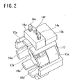
- the B-phase stator unit is framed as shown in Fig. 2 .
- the guide block 13b of the cover ring 13 and the terminal block 14c of the bobbin 14 are engagingly sandwiched between two adjacent pole teeth out of the pole teeth 12a of the first stator yoke 12, whereby the cover ring 13 and the bobbin 14 can be duly positioned with respect to the first stator yoke 12 in the circumferential direction.
- the bobbin 14 can be duly positioned with respect to the second stator yoke 16 in the circumferential direction by means of the boss 14b of the bobbin 14 engagingly fitting into the pit 16b of the second stator yoke 16 as described above.
- the B-phase stator units framed as shown in Fig. 2 is resin-molded by, for example, injection molding to be integrated for solidification.
- a claw-pole type stepping motor 1 according to a preferred embodiment of the present invention comprises the above-described B-phase stator unit 10 resin-molded, the aforementioned A-phase stator unit 20 resin-molded, a rotor assembly 30, a front plate 36, a rear plate 37, and pins 34 and 35 for securely holding together the parts in place.
- the B-phase stator unit 10 is resin-molded as described above so as to have a resin portion 17, and holes 17a for passing the pins 34 and 35 are formed in the resin portion 17 at the time of resin-molding.
- the A-phase stator unit 20 is structured in the same way as the B-phase stator unit 10 with only difference found in the location of the holes for passing the pins 34 and 35, and therefore a detailed explanation thereof is omitted.
- the rotor assembly 30 includes a rotor magnet 31 constituted by, for example, a rare-earth cylindrical magnet and having a outer diameter of some 5 mm, and a rotary shaft 33 formed of, for example, stainless steel, and washers 32 formed of, for example, stainless steel are put on the rotary shaft 33.
- the front plate 36 which may be formed of a magnetic or nonmagnetic material, has holes 36a for passing the pins 34 and 35, and the pins 34 and 35 are, for example, riveted to be fixed at the holes 36a.
- the rear plate 37 which may also be formed of a magnetic or nonmagnetic material, has holes 37a for passing the pins 34 and 35, and the pins 34 and 35 are, for example, riveted to be fixed at the holes 37a.
- the motor 1 is assembled such that the constituent parts described above are put together in an axial direction in reference-numerical order.
- the pins 34 and 35 are inserted through respective holes 36a of the front plate 36, the A-phase stator unit 20, the B-phase stator unit 10, and the rear plate 37, and have their respective both ends, for example, riveted for fixation, whereby the parts are duly and fixedly positioned with respect to one another in the circumferential direction.
- the motor 1 has the rotary shaft 33 disposed at the center, and the rotor magnet 31 is mounted on the rotary shaft 33.
- the body section 13a of the cover ring 13 is disposed so as to be in contact with the flanges 14a' and 14a" of the bobbin 14 which sandwich the magnet wire 14d wound around the bobbin 14, and prevents injected resin from getting to the magnet wire 14d. This way, the magnet wire 14d is protected against the injected resin and therefore prevented from deteriorating or breaking when the stator units are resin-molded for integration.
- the cover ring 13 is put on the bobbin 14 preferably with the body section 13a set in touch with the outer circumference of at least one of the flanges 14a' and 14a", so that the cover ring 13 is held coaxial to the bobbin 14.
- the guide block 13b of the cover ring 13 is at least partly in touch with the terminal block 14c of the bobbin 14, whereby the injected resin is prevented from getting to the end portions of the magnet wire 14d leading out to the terminal pins 14e, and whereby the terminal block 14c is stopped from moving in the axial direction due to molding pressure at the process of resin-molding.
- the groove 13c provided at the guide block 13b allows the magnet wire 14d wound around the bobbin 14 to lead out to the terminal pins 14e.
- the motor 1 shown in Fig. 4 is perspectively viewed from its rear side, omitting the rear plate 37, the B-phase stator unit 10, the rotor assembly 30, and the washers 32.
- the boss 14b of the bobbin 14 fits engagingly into the pit 16b of the second stator yoke 16 so as to fixedly position the bobbin 14 with respect to the second stator yoke 16 in the circumferential direction.
- the positioning may alternatively be implemented, for example, such that a notch provided on the second stator yoke 16 in place of the pit 16b is set to a predetermined marker at the process of resin-molding.
- the groove 14f which is formed on the terminal block 14c of the bobbin 14, and which is intended to serve as a hooking mechanism for the magnet wire 14d at the process of winding, works, together with the groove 13c of the guide block 13b of the cover ring 13, also as a guide passage for the end portions of the magnet wire 14d leading to the terminal pins 14e, thus the magnet wire 14d is surely and reliably allowed to lead out to the terminal pins 14e.
- Fig. 7 shows that the motor 1 structured according to a preferred embodiment of the present invention is downsized so as to measure as small as 6 mm in height.
- the bridging portion between the flange 14a' and the terminal block 14c on the bobbin 14 has a width adapted to fit engagingly between two adjacent pole teeth of the pole teeth 12a of the first stator yoke 12 thereby fixedly positioning the bobbin 14 with respect to the first stator yoke 12 in the circumferential direction.
- the bridging portion between the body section 13a and the guide block 13b on the ring cover 13 has a width adapted to fit engagingly between the two adjacent pole teeth of the pole teeth 12a of the first stator yoke 12 thereby fixedly positioning the cover ring 13 with respect to the first stator yoke 12 in the circumferential direction.
- the cover ring 13 is put on the bobbin 14 such that the body section 13a covers the outer circumferences of the flanges 14a' and 14a", whereby the magnet wire 14d wound around the body section 14a between the flanges 14a' and 14a" is protected.
- the motor according to the present invention may have a round, rectangular or otherwise configured radial cross section according to a housing space configuration.
Description
- The present invention relates to a structure of a claw-pole type stepping motor, and particularly to a structure thereof for achieving reduction in dimension and offering technical advantages.
- As various electronic devices are increasingly requested to be downsized, motors incorporated in the devices are also requested to be downsized. In a conventional claw-pole type stepping motor with an inner rotor, A-phase and B-phase driving coils are typically disposed so as to surround the outer circumference of a rotor. In such a claw-pole type stepping motor, the diameter of a rotor magnet is restricted by the inner diameter of a stator, so a motor with a smaller dimension is forced to have a rotor magnet with a smaller diameter thus resulting in significant deterioration in motor characteristic. This makes it difficult for a claw-pole type stepping motor with a small radial dimension to ensure performance characteristic required for position control. In such a case, a brushless DC motor equipped with an encoder as a position detector must be used in place of a claw-pole type stepping motor, which inevitably pushes up production cost.
- Under the aforementioned circumstances,
Japanese Patent Application Laid-Open No. 2003-009497 Japanese Patent Application Laid-Open No. 2003-009497 -
JP-A-10 327570 US-A-2 922 932 discloses a bobbin for a synchronous electric motor having a ring-shaped cover for the winding and the bobbin terminal block.EP-A-1 394 922 discloses a claw-pole stepping motor with a rotor and pair of units having a wound bobbin and a cover ring which protects the coil during moulding. - The present invention has been made in light of the above circumstances, and it is an object of the present invention to overcome the difficulty in resin-molding a stator to thereby eliminate a motor case for a claw-pole type stepping motor in order to downsize its radial dimension while maintaining its mechanical strength.
- According to the present invention there is provided a claw-pole type stapping motor as claimed in
claim 1. - The present invention provides a claw-pole type stepping motor comprising a rotor assembly and two cup-shaped stator units. The rotor assembly is shaped substantially cylindrical and has a rotor magnet and a rotary shaft at its center. The two cup-shaped stator units each comprise a bobbin having two flanges, a coil with a magnet wire wound around the bobbin between the two flanges of the bobbin and two stator yokes positioned on opposite sides of the bobbin and magnetically connected to each other, the stator yokes having respective pole tooth arrays which are shifted in phase from each other by an electrical angle of 180 degrees, which extend from the respective yoke in the same direction and which project axially beyond the same side of the bobbin. The stator units are coupled to each other coaxially so as to axially sandwich the rotor magnet with their coils located respectively toward both axial end faces of the rotor magnet and their pole tooth arrays surrounding the rotor magnet. Each of the stator units further includes a cover ring which is in contact with the two flanges of the bobbin so as to protect the magnet wire wound around the bobbin against resin injected when the stator unit is resin molded for an integrated solid structure. The bobbin includes a terminal block provided with terminals to conduct supply current to the magnet wire, and the cover ring includes a guide block which is at least partly in touch with the terminal block so as to protect end portions of the magnet wire leading out to the terminals against the resin injected.
- The cover ring is in contact with the two flanges such that the cover ring touches an outer circumference of each of the two flanges so as to protect the magnet wire wound between the two flanges against the resin injected. Consequently, the resin injected is prevented from getting to the magnet wire wound around the bobbin, and also the bobbin and the cover ring are held coaxial to each other when positioned.
- The bobbin includes a terminal block provided with terminals to conduct supply current to the magnet wire, and the cover ring includes a guide block which is at least partly in touch with the terminal block so as to protect the end portions of the magnet wire leading out to the terminals against the resin injected. Consequently, the bobbin is stopped from moving in the axial direction due to molding pressure at the time of resin-molding the stator unit for an integrated structure.
- Consequently, the difficulty with resin-molding the stator unit for an integrated solid structure is overcome, and a motor case for entirely covering a motor can be eliminated thus downsizing the motor with a sufficient mechanical strength ensured.
- The guide block of the cover ring may have a groove which allows the magnet wire to lead out to the terminals. Consequently, the stator unit is resin-molded with a guide passage ensured for leading out the magnet wire to the terminals.
- Further, since the two stator units structured as described above are coupled to each other, pins may be inserted though respective holes formed on the stator units when resin-molded and riveted for fixation, a sufficient strength is provided for the motor assembled.
-
Fig. 1 is an exploded perspective view of one stator unit for a claw-pole type stepping motor according to an embodiment of the present invention; -
Fig. 2 is a perspective view of a framed state of the one stator unit shown inFig. 1 ; -
Fig. 3 is an exploded perspective view of the claw-pole type stepping motor according to the embodiment of the present invention; -
Fig. 4 is a sectioned perspective view of the motor shown inFig. 3 ; -
Fig. 5 is a perspective view of the motor ofFig. 4 seen from a rear side, omitting arear plate 37, a B-phase stator unit 10, arotor assembly 30, andwashers 32; -
Fig. 6 is a perspective view of the motor ofFig. 4 seen from a front side; -
Fig. 7 is a perspective view of the motor ofFig. 4 seen from the rear side; -
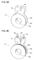
Figs. 8A and 8B are perspective views of abobbin 14 shown inFig. 1 seen from a side opposite to a side as seen inFig. 1 , whereinFig. 8A omits amagnet wire 14d andterminal pins 14e; -
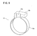
Fig. 9 is a perspective view of acover ring 13 shown inFig. 1 ; and -
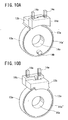
Figs. 10A and 10B are perspective views of thebobbin 14 ofFig. 8B with thecover ring 13 ofFig. 9 put thereon, seen from both sides, respectively. - An embodiment of the present invention will hereinafter be described with reference to the accompanying drawings.
- A stepping motor according to the present invention comprises two stator units, specifically an A-phase stator unit and a B-phase stator unit arranged coaxially to each other. The B-phase stator unit is shown in
Fig. 1 in an exploded manner so as to explain its constituent parts. The A-phase stator unit uses common constituent parts to the B-phase stator unit and an explanation thereof will be omitted. Since the A-phase and B-phase stator units use common constituent parts, the production cost of the parts can be reduced. - Referring to
Fig. 1 , the B-phase stator includes abearing 11, afirst stator yoke 12, acover ring 13, abobbin 14, acore 15, and asecond stator yoke 16. - The
bearing 11 is, for example, a sintered sleeve bearing to rotatably support a rotary shaft of a rotor assembly to be described later. - The first and
second stator yokes respective pole teeth core 15, and are coupled to each other with therespective pole teeth second stator yoke 16 has apit 16b which engages with aboss 14b provided on thebobbin 14, whereby thesecond stator yoke 16 and thebobbin 14 are duly positioned with respect to each other in a circumferential direction for resin-molding process. - The
core 15 is formed of a soft magnetic plate, such as an SECC, a silicon plate steel, and an SUY, and has a center hole for allowing the rotary shaft of the rotor assembly to pass through. - The
bobbin 14 is formed of, for example, liquid crystal polymer, and made up of abody section 14a,flanges 14a' and 14a" sandwiching thebody section 14a, and aterminal block 14c. Amagnet wire 14d is wound around thebody section 14a between theflanges 14a' and 14a", andterminal pins 14e for supplying current to themagnet wire 14d are attached to theterminal block 14c. Thebobbin 14 is provided with theaforementioned boss 14b which fits engagingly into theaforementioned pit 16b of thesecond stator yoke 16 for positioning function as mentioned above. The mechanism for positioning thebobbin 14 with respect to thesecond stator yoke 16 may alternatively be structured such that thesecond stator yoke 16 is provided with a boss while thebobbin 14 is provided with a pit, or may be constituted by means of a positioning marker, such as a notch, provided appropriately. Theterminal block 14c has agroove 14f which functions mainly as a mechanism for hooking themagnet wire 14d when themagnet wire 14d is wound around thebobbin 14. - The
cover ring 13 is formed of, for example, liquid crystal polymer, made up of abody section 13a and aguide block 13b, and protects themagnet wire 14d wound around thebobbin 14 against resin injected for molding the B-phase stator unit for integrated structure. Theguide block 13b has agroove 13c which allows the terminal ends of themagnet wire 14d wound around thebobbin 14 to lead out to theterminal pins 14e when thecover ring 13 is attached onto thebobbin 14 thereby bringing theguide block 13b in contact with theterminal block 14c. - The above-described constituent parts are put together in an axial direction in reference-numerical order, and the B-phase stator unit is framed as shown in
Fig. 2 . When the B-phase stator unit is duly framed, theguide block 13b of thecover ring 13 and theterminal block 14c of thebobbin 14 are engagingly sandwiched between two adjacent pole teeth out of thepole teeth 12a of thefirst stator yoke 12, whereby thecover ring 13 and thebobbin 14 can be duly positioned with respect to thefirst stator yoke 12 in the circumferential direction. And, thebobbin 14 can be duly positioned with respect to thesecond stator yoke 16 in the circumferential direction by means of theboss 14b of thebobbin 14 engagingly fitting into thepit 16b of thesecond stator yoke 16 as described above. The B-phase stator units framed as shown inFig. 2 is resin-molded by, for example, injection molding to be integrated for solidification. - Referring to
Fig. 3 , a claw-poletype stepping motor 1 according to a preferred embodiment of the present invention comprises the above-described B-phase stator unit 10 resin-molded, the aforementionedA-phase stator unit 20 resin-molded, arotor assembly 30, afront plate 36, arear plate 37, and pins 34 and 35 for securely holding together the parts in place. - The B-
phase stator unit 10 is resin-molded as described above so as to have aresin portion 17, and holes 17a for passing thepins resin portion 17 at the time of resin-molding. TheA-phase stator unit 20 is structured in the same way as the B-phase stator unit 10 with only difference found in the location of the holes for passing thepins - The
rotor assembly 30 includes arotor magnet 31 constituted by, for example, a rare-earth cylindrical magnet and having a outer diameter of some 5 mm, and arotary shaft 33 formed of, for example, stainless steel, andwashers 32 formed of, for example, stainless steel are put on therotary shaft 33. - The
front plate 36, which may be formed of a magnetic or nonmagnetic material, hasholes 36a for passing thepins pins holes 36a. - The
rear plate 37, which may also be formed of a magnetic or nonmagnetic material, hasholes 37a for passing thepins pins holes 37a. - The
motor 1 is assembled such that the constituent parts described above are put together in an axial direction in reference-numerical order. In the assembling process, thepins respective holes 36a of thefront plate 36, theA-phase stator unit 20, the B-phase stator unit 10, and therear plate 37, and have their respective both ends, for example, riveted for fixation, whereby the parts are duly and fixedly positioned with respect to one another in the circumferential direction. - Referring now to
Fig. 4 , themotor 1 has therotary shaft 33 disposed at the center, and therotor magnet 31 is mounted on therotary shaft 33. Thebody section 13a of thecover ring 13 is disposed so as to be in contact with theflanges 14a' and 14a" of thebobbin 14 which sandwich themagnet wire 14d wound around thebobbin 14, and prevents injected resin from getting to themagnet wire 14d. This way, themagnet wire 14d is protected against the injected resin and therefore prevented from deteriorating or breaking when the stator units are resin-molded for integration. Thecover ring 13 is put on thebobbin 14 preferably with thebody section 13a set in touch with the outer circumference of at least one of theflanges 14a' and 14a", so that thecover ring 13 is held coaxial to thebobbin 14. Also, theguide block 13b of thecover ring 13 is at least partly in touch with theterminal block 14c of thebobbin 14, whereby the injected resin is prevented from getting to the end portions of themagnet wire 14d leading out to theterminal pins 14e, and whereby theterminal block 14c is stopped from moving in the axial direction due to molding pressure at the process of resin-molding. And, it is realized fromFig. 4 that thegroove 13c provided at theguide block 13b allows themagnet wire 14d wound around thebobbin 14 to lead out to theterminal pins 14e. - Referring to
Fig. 5 , themotor 1 shown inFig. 4 is perspectively viewed from its rear side, omitting therear plate 37, the B-phase stator unit 10, therotor assembly 30, and thewashers 32. Theboss 14b of thebobbin 14 fits engagingly into thepit 16b of thesecond stator yoke 16 so as to fixedly position thebobbin 14 with respect to thesecond stator yoke 16 in the circumferential direction. The positioning may alternatively be implemented, for example, such that a notch provided on thesecond stator yoke 16 in place of thepit 16b is set to a predetermined marker at the process of resin-molding. - Referring to
Figs. 6 and7 , it is known that thegroove 14f, which is formed on theterminal block 14c of thebobbin 14, and which is intended to serve as a hooking mechanism for themagnet wire 14d at the process of winding, works, together with thegroove 13c of theguide block 13b of thecover ring 13, also as a guide passage for the end portions of themagnet wire 14d leading to theterminal pins 14e, thus themagnet wire 14d is surely and reliably allowed to lead out to theterminal pins 14e.Fig. 7 shows that themotor 1 structured according to a preferred embodiment of the present invention is downsized so as to measure as small as 6 mm in height. - Referring to
Figs. 8A and 8B , the bridging portion between theflange 14a' and theterminal block 14c on thebobbin 14 has a width adapted to fit engagingly between two adjacent pole teeth of thepole teeth 12a of thefirst stator yoke 12 thereby fixedly positioning thebobbin 14 with respect to thefirst stator yoke 12 in the circumferential direction. - Referring to
Fig. 9 , the bridging portion between thebody section 13a and theguide block 13b on thering cover 13 has a width adapted to fit engagingly between the two adjacent pole teeth of thepole teeth 12a of thefirst stator yoke 12 thereby fixedly positioning thecover ring 13 with respect to thefirst stator yoke 12 in the circumferential direction. - Referring to
Figs. 10A and 10B , thecover ring 13 is put on thebobbin 14 such that thebody section 13a covers the outer circumferences of theflanges 14a' and 14a", whereby themagnet wire 14d wound around thebody section 14a between theflanges 14a' and 14a" is protected. - In the above description of the embodiment according to the present invention, a conventionally required motor case for entirely covering a motor is eliminated thereby achieving downsizing, but if the motor cover is eliminated with the motor size remaining unchanged, then the dimension of its components can be increased thereby enhancing its motor characteristic. Also, the motor according to the present invention may have a round, rectangular or otherwise configured radial cross section according to a housing space configuration.
- While the present invention has been illustrated and explained with respect to a specific embodiment thereof, it is to be understood that the present invention is by no means limited thereto but encompasses all changes and modifications that will become possible within the scope of the appended claims.
Claims (2)
- A claw-pole type stepping motor comprising:a rotor assembly (30) which is shaped substantially cylindrical, and which has a rotor magnet (31) and a rotary shaft (33) at its center; andtwo cup-shaped stator units (10, 20), each comprising:a bobbin (14) having two flanges (14a', 14a");a coil with a magnet wire (14d) wound around the bobbin (14) between the two flanges of the bobbin (14); andtwo stator yokes (12, 16) positioned on opposite sides of the bobbin and magnetically connected to each other, the stator yokes (12, 16) having respective pole tooth arrays (12a, 16a) which are shifted in phase from each other by an electrical angle of 180 degrees, which extend from the respective yoke in the same direction and which project axially beyond the same side of the bobbin (14);wherein the stator units (10, 20) are coupled to each other coaxially so as to axially sandwich the rotor magnet (31) with their coils located respectively toward both axial end faces of the rotor magnet (31) and their pole tooth arrays (12a, 16a) surrounding the rotor magnet (31);CHARACTERIZED IN THAT:the bobbin (14) includes a terminal block (14c) provided with terminals (14e) to conduct supply current to the magnet wire;each of the stator units (10, 20) further includes a cover ring (13) which is in contact with the two flanges of the bobbin (14) so as to protect the magnet wire (14d) wound around the bobbin (14) against resin injected when the stator unit (10, 20) is resin molded for an integrated solid structure; andthe cover ring (13) comprises a guide block (13b) disposed to be at least partly in touch with the terminal block (14c) so as to protect end portions of the magnet wire leading out to the terminals (14e) against the resin injected;wherein the cover ring (13) is in contact with an outer circumference of each of the two flanges.
- A claw-pole type stepping motor according to claim 1, wherein the guide block (13b) of the cover ring (13) has a groove which allows the magnet wire to lead out to the terminals.
Applications Claiming Priority (2)
| Application Number | Priority Date | Filing Date | Title |
|---|---|---|---|
| JP2003310329A JP3825024B2 (en) | 2003-09-02 | 2003-09-02 | Claw pole type stepping motor |
| JP2003310329 | 2003-09-02 |
Publications (2)
| Publication Number | Publication Date |
|---|---|
| EP1513242A1 EP1513242A1 (en) | 2005-03-09 |
| EP1513242B1 true EP1513242B1 (en) | 2008-11-26 |
Family
ID=34131818
Family Applications (1)
| Application Number | Title | Priority Date | Filing Date |
|---|---|---|---|
| EP04255288A Expired - Fee Related EP1513242B1 (en) | 2003-09-02 | 2004-09-01 | Claw-pole type stepping motor |
Country Status (4)
| Country | Link |
|---|---|
| US (1) | US7071593B2 (en) |
| EP (1) | EP1513242B1 (en) |
| JP (1) | JP3825024B2 (en) |
| DE (1) | DE602004017944D1 (en) |
Families Citing this family (38)
| Publication number | Priority date | Publication date | Assignee | Title |
|---|---|---|---|---|
| JP3515511B2 (en) * | 2000-10-30 | 2004-04-05 | 三菱電機株式会社 | Electromagnetic equipment |
| US7446442B2 (en) * | 2004-04-21 | 2008-11-04 | Canon Kabushiki Kaisha | Stepping motor and drive device |
| JP4297037B2 (en) * | 2004-11-11 | 2009-07-15 | 株式会社デンソー | Stepping motor |
| JP4684689B2 (en) * | 2005-03-14 | 2011-05-18 | 日本電産サンキョー株式会社 | Stepping motor |
| JP2006296086A (en) * | 2005-04-11 | 2006-10-26 | Minebea-Matsushita Motor Corp | Stepping motor with lead screw |
| KR100811956B1 (en) * | 2005-07-05 | 2008-03-10 | 엘지이노텍 주식회사 | Bobbin structure of stepping motor |
| CN1945943B (en) * | 2005-10-09 | 2011-02-09 | 精工电子有限公司 | Step motor and electronic equipment |
| CN1945944A (en) * | 2005-10-09 | 2007-04-11 | 精工电子有限公司 | Step motor and electronic equipment |
| DE102006021247B4 (en) * | 2006-04-28 | 2012-02-02 | Bühler Motor GmbH | electric motor |
| DE102006026719B4 (en) * | 2006-06-08 | 2012-04-26 | Minebea Co., Ltd. | Claw cushion for a stepper motor and claw-pole stepper motor |
| US20080024022A1 (en) * | 2006-07-26 | 2008-01-31 | Chun-Pin Wu | Motor wiring seat for a motor |
| JP4815299B2 (en) * | 2006-07-31 | 2011-11-16 | 日本電産サンキョー株式会社 | Motor and manufacturing method thereof |
| JP2008263691A (en) * | 2007-04-11 | 2008-10-30 | Minebea Co Ltd | Small diameter stepping motor, its bobbin, and assembly method of motor |
| EP2149189A2 (en) | 2007-05-09 | 2010-02-03 | Motor Excellence, LLC | Tape wound core laminate rotor or stator elements |
| US7868511B2 (en) * | 2007-05-09 | 2011-01-11 | Motor Excellence, Llc | Electrical devices using disk and non-disk shaped rotors |
| WO2008156316A2 (en) * | 2007-06-19 | 2008-12-24 | Lg Innotek Co., Ltd | Stepping motor |
| JP5172225B2 (en) * | 2007-06-21 | 2013-03-27 | ミネベア株式会社 | PM stepping motor |
| CN201153222Y (en) * | 2007-12-17 | 2008-11-19 | 上海鸣志电器有限公司 | Step motor pole |
| WO2010062766A2 (en) * | 2008-11-03 | 2010-06-03 | Motor Excellence, Llc | Polyphase transverse and/or commutated flux systems |
| WO2010110575A2 (en) * | 2009-03-23 | 2010-09-30 | 엘지이노텍 주식회사 | Stepping motor |
| CN101901661B (en) * | 2009-05-26 | 2011-12-21 | 浙江三花股份有限公司 | Electromagnetic coil device |
| US8278803B2 (en) * | 2009-08-14 | 2012-10-02 | Lin Engineering | Motor end cap positioning element for maintaining rotor-stator concentricity |
| JP5566071B2 (en) * | 2009-09-24 | 2014-08-06 | 日本電産サンキョー株式会社 | Coil winding body and motor |
| KR101658348B1 (en) * | 2010-03-03 | 2016-10-04 | 주식회사 모아텍 | Step motor |
| CN102959832B (en) | 2010-03-15 | 2016-11-16 | 电扭矩机器股份有限公司 | There is the horizontal of phase deviation and/or commutation throughput systems |
| WO2011115632A1 (en) | 2010-03-15 | 2011-09-22 | Motor Excellence Llc | Transverse and/or commutated flux systems configured to provide reduced flux leakage, hysteresis loss reduction, and phase matching |
| US8395291B2 (en) | 2010-03-15 | 2013-03-12 | Electric Torque Machines, Inc. | Transverse and/or commutated flux systems for electric bicycles |
| DE202010015364U1 (en) * | 2010-11-11 | 2012-02-17 | Hans-Peter Wyremba | Brushless electric motor or generator in shell construction |
| CN103477538A (en) | 2010-11-17 | 2013-12-25 | 电动转矩机器公司 | Transverse and/or commutated flux systems having segmented stator laminations |
| WO2012067896A2 (en) | 2010-11-17 | 2012-05-24 | Motor Excellence, Llc | Transverse and/or commutated flux systems having laminated and powdered metal portions |
| WO2012067895A2 (en) | 2010-11-17 | 2012-05-24 | Motor Excellence, Llc | Transverse and/or commutated flux system coil concepts |
| JP5496154B2 (en) * | 2011-06-29 | 2014-05-21 | シナノケンシ株式会社 | Outer rotor type stator structure |
| JP2013093939A (en) * | 2011-10-25 | 2013-05-16 | Nidec Sankyo Corp | Bobbin with terminal and motor |
| JP6382213B2 (en) * | 2012-11-30 | 2018-08-29 | アプライド マテリアルズ インコーポレイテッドApplied Materials,Incorporated | Motor module, multi-axis motor drive assembly, multi-axis robot apparatus, and electronic device manufacturing system and method |
| CN103780039A (en) * | 2014-01-16 | 2014-05-07 | 南京航空航天大学 | Rotor circuit double-ended excitation type hybrid excitation electrical machine |
| EP3136553B1 (en) * | 2015-08-26 | 2017-10-11 | Lakeview Innovation Ltd. | Stator system with a sheathing of plastic with improved heat dissipation and method for producing the same |
| WO2018003105A1 (en) * | 2016-06-30 | 2018-01-04 | 株式会社安川電機 | Rotating electrical machine and system for driving rotating electrical machine |
| CN108448757B (en) * | 2018-05-08 | 2019-08-13 | 大连碧蓝节能环保科技有限公司 | Lundell pole-changing generator rotor |
Family Cites Families (13)
| Publication number | Priority date | Publication date | Assignee | Title |
|---|---|---|---|---|
| US2922932A (en) * | 1956-06-25 | 1960-01-26 | Sessions Clock Co | Magnetic coils |
| US4047061A (en) * | 1973-03-16 | 1977-09-06 | P. R. Mallory & Co., Inc. | Coil protector for permanent magnet synchronous motor |
| DE2829945C2 (en) * | 1978-07-05 | 1983-10-27 | Schleicher Gmbh & Co Relais-Werke Kg, 1000 Berlin | Synchronous motor with stator housing and permanent magnetic rotor |
| DE3211716C2 (en) | 1982-03-30 | 1985-12-05 | Siemens AG, 1000 Berlin und 8000 München | Bobbin |
| JPS6277855A (en) * | 1985-09-30 | 1987-04-10 | Shibaura Eng Works Co Ltd | Stepping motor |
| JPH0297883U (en) | 1989-01-21 | 1990-08-03 | ||
| AU660249B2 (en) * | 1993-07-08 | 1995-06-15 | Mitsubishi Materials Corporation | Stepping motor |
| JPH10327570A (en) | 1997-05-23 | 1998-12-08 | Matsushita Electric Ind Co Ltd | Stepping motor |
| US5912518A (en) * | 1997-10-22 | 1999-06-15 | Misik; Michael F. | Motor coil assembly |
| JP3711252B2 (en) | 2001-06-13 | 2005-11-02 | ミネベア株式会社 | Claw pole type stepping motor |
| JP3979039B2 (en) | 2001-06-22 | 2007-09-19 | 松下電器産業株式会社 | Stepping motor |
| JP3979037B2 (en) | 2001-06-22 | 2007-09-19 | 松下電器産業株式会社 | Stepping motor |
| JP4187573B2 (en) | 2002-08-30 | 2008-11-26 | ミネベア株式会社 | Motor bobbin |
-
2003
- 2003-09-02 JP JP2003310329A patent/JP3825024B2/en not_active Expired - Fee Related
-
2004
- 2004-08-30 US US10/929,184 patent/US7071593B2/en not_active Expired - Fee Related
- 2004-09-01 DE DE602004017944T patent/DE602004017944D1/en not_active Expired - Fee Related
- 2004-09-01 EP EP04255288A patent/EP1513242B1/en not_active Expired - Fee Related
Also Published As
| Publication number | Publication date |
|---|---|
| US7071593B2 (en) | 2006-07-04 |
| JP2005080461A (en) | 2005-03-24 |
| US20050046305A1 (en) | 2005-03-03 |
| EP1513242A1 (en) | 2005-03-09 |
| DE602004017944D1 (en) | 2009-01-08 |
| JP3825024B2 (en) | 2006-09-20 |
Similar Documents
| Publication | Publication Date | Title |
|---|---|---|
| EP1513242B1 (en) | Claw-pole type stepping motor | |
| US5073735A (en) | Stepping motor having a molded housing | |
| US6411006B2 (en) | Electric rotary machine | |
| US5298820A (en) | Miniature motor with integrated stator coil end supports | |
| JP3911671B2 (en) | motor | |
| JP2010178436A (en) | Bus bar unit, motor, and power steering system | |
| JP4038664B2 (en) | Stepping motor | |
| KR20160139824A (en) | Stator and motor using the same | |
| EP1583202B1 (en) | Stepping motor with dual-layer bobbin cover | |
| EP1496598B1 (en) | Claw-pole type stepping motor having radial dimension reduced without detriment to performance characteristic | |
| JPH0588169U (en) | Small motor | |
| JP4187573B2 (en) | Motor bobbin | |
| JP2007221977A (en) | Brushless motor | |
| KR20150040527A (en) | Motor | |
| JP2007209128A (en) | Motor and fuel pump employing the same | |
| CN108702054B (en) | Axial gap type rotating electric machine | |
| US7183676B2 (en) | Stepping motor | |
| JP2007159191A (en) | Motor | |
| JP2004048851A (en) | Rotary electric machine | |
| CN111509871B (en) | Stator, motor and air supply device | |
| CN113541342A (en) | Outer rotor type motor | |
| JP3979039B2 (en) | Stepping motor | |
| JP3979037B2 (en) | Stepping motor | |
| KR102321183B1 (en) | stator insulation structure for air-compressor | |
| JP3979038B2 (en) | Stepping motor |
Legal Events
| Date | Code | Title | Description |
|---|---|---|---|
| PUAI | Public reference made under article 153(3) epc to a published international application that has entered the european phase |
Free format text: ORIGINAL CODE: 0009012 |
|
| AK | Designated contracting states |
Kind code of ref document: A1 Designated state(s): AT BE BG CH CY CZ DE DK EE ES FI FR GB GR HU IE IT LI LU MC NL PL PT RO SE SI SK TR |
|
| AX | Request for extension of the european patent |
Extension state: AL HR LT LV MK |
|
| 17P | Request for examination filed |
Effective date: 20050323 |
|
| AKX | Designation fees paid |
Designated state(s): DE FR GB IT |
|
| 17Q | First examination report despatched |
Effective date: 20060328 |
|
| GRAP | Despatch of communication of intention to grant a patent |
Free format text: ORIGINAL CODE: EPIDOSNIGR1 |
|
| RIN1 | Information on inventor provided before grant (corrected) |
Inventor name: NAGATA, TOSHIHIKO,MINEBEA CO., LTD. Inventor name: YAMAWAKI, TAKAYUKI,MINEBEA CO., LTD. Inventor name: MATSUSHITA, KUNITAKE,MINEBEA CO., LTD. |
|
| GRAS | Grant fee paid |
Free format text: ORIGINAL CODE: EPIDOSNIGR3 |
|
| GRAA | (expected) grant |
Free format text: ORIGINAL CODE: 0009210 |
|
| AK | Designated contracting states |
Kind code of ref document: B1 Designated state(s): DE FR GB IT |
|
| REG | Reference to a national code |
Ref country code: GB Ref legal event code: FG4D |
|
| REF | Corresponds to: |
Ref document number: 602004017944 Country of ref document: DE Date of ref document: 20090108 Kind code of ref document: P |
|
| PLBE | No opposition filed within time limit |
Free format text: ORIGINAL CODE: 0009261 |
|
| STAA | Information on the status of an ep patent application or granted ep patent |
Free format text: STATUS: NO OPPOSITION FILED WITHIN TIME LIMIT |
|
| 26N | No opposition filed |
Effective date: 20090827 |
|
| GBPC | Gb: european patent ceased through non-payment of renewal fee |
Effective date: 20090901 |
|
| REG | Reference to a national code |
Ref country code: FR Ref legal event code: ST Effective date: 20100531 |
|
| PG25 | Lapsed in a contracting state [announced via postgrant information from national office to epo] |
Ref country code: FR Free format text: LAPSE BECAUSE OF NON-PAYMENT OF DUE FEES Effective date: 20090930 Ref country code: DE Free format text: LAPSE BECAUSE OF NON-PAYMENT OF DUE FEES Effective date: 20100401 |
|
| PG25 | Lapsed in a contracting state [announced via postgrant information from national office to epo] |
Ref country code: GB Free format text: LAPSE BECAUSE OF NON-PAYMENT OF DUE FEES Effective date: 20090901 |
|
| PG25 | Lapsed in a contracting state [announced via postgrant information from national office to epo] |
Ref country code: IT Free format text: LAPSE BECAUSE OF FAILURE TO SUBMIT A TRANSLATION OF THE DESCRIPTION OR TO PAY THE FEE WITHIN THE PRESCRIBED TIME-LIMIT Effective date: 20081126 |