EP1511446B1 - Endoprosthesis having pressure, temperature, and flow sensors - Google Patents
Endoprosthesis having pressure, temperature, and flow sensors Download PDFInfo
- Publication number
- EP1511446B1 EP1511446B1 EP03734408A EP03734408A EP1511446B1 EP 1511446 B1 EP1511446 B1 EP 1511446B1 EP 03734408 A EP03734408 A EP 03734408A EP 03734408 A EP03734408 A EP 03734408A EP 1511446 B1 EP1511446 B1 EP 1511446B1
- Authority
- EP
- European Patent Office
- Prior art keywords
- prosthesis
- endovascular graft
- sensors
- endovascular
- graft component
- Prior art date
- Legal status (The legal status is an assumption and is not a legal conclusion. Google has not performed a legal analysis and makes no representation as to the accuracy of the status listed.)
- Expired - Fee Related
Links
- 206010002329 Aneurysm Diseases 0.000 claims description 39
- 208000001750 Endoleak Diseases 0.000 claims description 26
- 206010064396 Stent-graft endoleak Diseases 0.000 claims description 16
- 230000017531 blood circulation Effects 0.000 claims description 13
- 239000000470 constituent Substances 0.000 claims description 9
- 210000005166 vasculature Anatomy 0.000 claims description 5
- 102000004190 Enzymes Human genes 0.000 claims description 3
- 108090000790 Enzymes Proteins 0.000 claims description 3
- QVGXLLKOCUKJST-UHFFFAOYSA-N atomic oxygen Chemical compound [O] QVGXLLKOCUKJST-UHFFFAOYSA-N 0.000 claims description 3
- 235000015097 nutrients Nutrition 0.000 claims description 3
- 229910052760 oxygen Inorganic materials 0.000 claims description 3
- 239000001301 oxygen Substances 0.000 claims description 3
- 102000004169 proteins and genes Human genes 0.000 claims description 3
- 108090000623 proteins and genes Proteins 0.000 claims description 3
- 238000001727 in vivo Methods 0.000 claims description 2
- 208000002223 abdominal aortic aneurysm Diseases 0.000 description 9
- 238000005259 measurement Methods 0.000 description 9
- 238000000034 method Methods 0.000 description 8
- 238000002513 implantation Methods 0.000 description 7
- 239000000463 material Substances 0.000 description 7
- 208000007536 Thrombosis Diseases 0.000 description 6
- 230000015572 biosynthetic process Effects 0.000 description 5
- 239000004744 fabric Substances 0.000 description 5
- 210000001367 artery Anatomy 0.000 description 4
- 239000008280 blood Substances 0.000 description 4
- 210000004369 blood Anatomy 0.000 description 4
- 239000007943 implant Substances 0.000 description 4
- 230000003447 ipsilateral effect Effects 0.000 description 4
- 230000008439 repair process Effects 0.000 description 4
- 210000003090 iliac artery Anatomy 0.000 description 3
- 208000015181 infectious disease Diseases 0.000 description 3
- 230000002085 persistent effect Effects 0.000 description 3
- 238000001356 surgical procedure Methods 0.000 description 3
- 241001465754 Metazoa Species 0.000 description 2
- 230000003187 abdominal effect Effects 0.000 description 2
- 230000001154 acute effect Effects 0.000 description 2
- 230000004872 arterial blood pressure Effects 0.000 description 2
- 230000005540 biological transmission Effects 0.000 description 2
- 238000009530 blood pressure measurement Methods 0.000 description 2
- 238000002591 computed tomography Methods 0.000 description 2
- 238000003384 imaging method Methods 0.000 description 2
- 230000009885 systemic effect Effects 0.000 description 2
- 206010061218 Inflammation Diseases 0.000 description 1
- 206010060872 Transplant failure Diseases 0.000 description 1
- 206010053692 Wound complication Diseases 0.000 description 1
- 238000012084 abdominal surgery Methods 0.000 description 1
- 238000002583 angiography Methods 0.000 description 1
- 238000010171 animal model Methods 0.000 description 1
- 208000007474 aortic aneurysm Diseases 0.000 description 1
- 230000036772 blood pressure Effects 0.000 description 1
- 210000004204 blood vessel Anatomy 0.000 description 1
- 238000009529 body temperature measurement Methods 0.000 description 1
- 230000002308 calcification Effects 0.000 description 1
- 239000003990 capacitor Substances 0.000 description 1
- 238000006243 chemical reaction Methods 0.000 description 1
- 238000001514 detection method Methods 0.000 description 1
- 238000009556 duplex ultrasonography Methods 0.000 description 1
- 238000005516 engineering process Methods 0.000 description 1
- 230000007717 exclusion Effects 0.000 description 1
- 238000001631 haemodialysis Methods 0.000 description 1
- 230000036541 health Effects 0.000 description 1
- 230000000322 hemodialysis Effects 0.000 description 1
- 238000010874 in vitro model Methods 0.000 description 1
- 230000004054 inflammatory process Effects 0.000 description 1
- 238000002608 intravascular ultrasound Methods 0.000 description 1
- 230000013011 mating Effects 0.000 description 1
- 210000004249 mesenteric artery inferior Anatomy 0.000 description 1
- 238000002324 minimally invasive surgery Methods 0.000 description 1
- 238000012806 monitoring device Methods 0.000 description 1
- 230000007170 pathology Effects 0.000 description 1
- 230000035699 permeability Effects 0.000 description 1
- 230000035479 physiological effects, processes and functions Effects 0.000 description 1
- 230000002980 postoperative effect Effects 0.000 description 1
- 230000009467 reduction Effects 0.000 description 1
- 238000002694 regional anesthesia Methods 0.000 description 1
- 238000007789 sealing Methods 0.000 description 1
Images

Classifications
-
- A—HUMAN NECESSITIES
- A61—MEDICAL OR VETERINARY SCIENCE; HYGIENE
- A61B—DIAGNOSIS; SURGERY; IDENTIFICATION
- A61B5/00—Measuring for diagnostic purposes; Identification of persons
- A61B5/07—Endoradiosondes
- A61B5/076—Permanent implantations
-
- A—HUMAN NECESSITIES
- A61—MEDICAL OR VETERINARY SCIENCE; HYGIENE
- A61B—DIAGNOSIS; SURGERY; IDENTIFICATION
- A61B5/00—Measuring for diagnostic purposes; Identification of persons
- A61B5/02—Detecting, measuring or recording pulse, heart rate, blood pressure or blood flow; Combined pulse/heart-rate/blood pressure determination; Evaluating a cardiovascular condition not otherwise provided for, e.g. using combinations of techniques provided for in this group with electrocardiography or electroauscultation; Heart catheters for measuring blood pressure
- A61B5/02007—Evaluating blood vessel condition, e.g. elasticity, compliance
- A61B5/02014—Determining aneurysm
-
- A—HUMAN NECESSITIES
- A61—MEDICAL OR VETERINARY SCIENCE; HYGIENE
- A61F—FILTERS IMPLANTABLE INTO BLOOD VESSELS; PROSTHESES; DEVICES PROVIDING PATENCY TO, OR PREVENTING COLLAPSING OF, TUBULAR STRUCTURES OF THE BODY, e.g. STENTS; ORTHOPAEDIC, NURSING OR CONTRACEPTIVE DEVICES; FOMENTATION; TREATMENT OR PROTECTION OF EYES OR EARS; BANDAGES, DRESSINGS OR ABSORBENT PADS; FIRST-AID KITS
- A61F2/00—Filters implantable into blood vessels; Prostheses, i.e. artificial substitutes or replacements for parts of the body; Appliances for connecting them with the body; Devices providing patency to, or preventing collapsing of, tubular structures of the body, e.g. stents
- A61F2/02—Prostheses implantable into the body
- A61F2/04—Hollow or tubular parts of organs, e.g. bladders, tracheae, bronchi or bile ducts
- A61F2/06—Blood vessels
- A61F2/07—Stent-grafts
-
- A—HUMAN NECESSITIES
- A61—MEDICAL OR VETERINARY SCIENCE; HYGIENE
- A61B—DIAGNOSIS; SURGERY; IDENTIFICATION
- A61B5/00—Measuring for diagnostic purposes; Identification of persons
- A61B5/01—Measuring temperature of body parts ; Diagnostic temperature sensing, e.g. for malignant or inflamed tissue
-
- A—HUMAN NECESSITIES
- A61—MEDICAL OR VETERINARY SCIENCE; HYGIENE
- A61B—DIAGNOSIS; SURGERY; IDENTIFICATION
- A61B5/00—Measuring for diagnostic purposes; Identification of persons
- A61B5/02—Detecting, measuring or recording pulse, heart rate, blood pressure or blood flow; Combined pulse/heart-rate/blood pressure determination; Evaluating a cardiovascular condition not otherwise provided for, e.g. using combinations of techniques provided for in this group with electrocardiography or electroauscultation; Heart catheters for measuring blood pressure
- A61B5/021—Measuring pressure in heart or blood vessels
- A61B5/0215—Measuring pressure in heart or blood vessels by means inserted into the body
-
- A—HUMAN NECESSITIES
- A61—MEDICAL OR VETERINARY SCIENCE; HYGIENE
- A61B—DIAGNOSIS; SURGERY; IDENTIFICATION
- A61B5/00—Measuring for diagnostic purposes; Identification of persons
- A61B5/02—Detecting, measuring or recording pulse, heart rate, blood pressure or blood flow; Combined pulse/heart-rate/blood pressure determination; Evaluating a cardiovascular condition not otherwise provided for, e.g. using combinations of techniques provided for in this group with electrocardiography or electroauscultation; Heart catheters for measuring blood pressure
- A61B5/026—Measuring blood flow
-
- A—HUMAN NECESSITIES
- A61—MEDICAL OR VETERINARY SCIENCE; HYGIENE
- A61B—DIAGNOSIS; SURGERY; IDENTIFICATION
- A61B5/00—Measuring for diagnostic purposes; Identification of persons
- A61B5/145—Measuring characteristics of blood in vivo, e.g. gas concentration, pH value; Measuring characteristics of body fluids or tissues, e.g. interstitial fluid, cerebral tissue
- A61B5/1455—Measuring characteristics of blood in vivo, e.g. gas concentration, pH value; Measuring characteristics of body fluids or tissues, e.g. interstitial fluid, cerebral tissue using optical sensors, e.g. spectral photometrical oximeters
- A61B5/1459—Measuring characteristics of blood in vivo, e.g. gas concentration, pH value; Measuring characteristics of body fluids or tissues, e.g. interstitial fluid, cerebral tissue using optical sensors, e.g. spectral photometrical oximeters invasive, e.g. introduced into the body by a catheter
-
- A—HUMAN NECESSITIES
- A61—MEDICAL OR VETERINARY SCIENCE; HYGIENE
- A61F—FILTERS IMPLANTABLE INTO BLOOD VESSELS; PROSTHESES; DEVICES PROVIDING PATENCY TO, OR PREVENTING COLLAPSING OF, TUBULAR STRUCTURES OF THE BODY, e.g. STENTS; ORTHOPAEDIC, NURSING OR CONTRACEPTIVE DEVICES; FOMENTATION; TREATMENT OR PROTECTION OF EYES OR EARS; BANDAGES, DRESSINGS OR ABSORBENT PADS; FIRST-AID KITS
- A61F2/00—Filters implantable into blood vessels; Prostheses, i.e. artificial substitutes or replacements for parts of the body; Appliances for connecting them with the body; Devices providing patency to, or preventing collapsing of, tubular structures of the body, e.g. stents
- A61F2/82—Devices providing patency to, or preventing collapsing of, tubular structures of the body, e.g. stents
- A61F2/86—Stents in a form characterised by the wire-like elements; Stents in the form characterised by a net-like or mesh-like structure
- A61F2/89—Stents in a form characterised by the wire-like elements; Stents in the form characterised by a net-like or mesh-like structure the wire-like elements comprising two or more adjacent rings flexibly connected by separate members
-
- A—HUMAN NECESSITIES
- A61—MEDICAL OR VETERINARY SCIENCE; HYGIENE
- A61F—FILTERS IMPLANTABLE INTO BLOOD VESSELS; PROSTHESES; DEVICES PROVIDING PATENCY TO, OR PREVENTING COLLAPSING OF, TUBULAR STRUCTURES OF THE BODY, e.g. STENTS; ORTHOPAEDIC, NURSING OR CONTRACEPTIVE DEVICES; FOMENTATION; TREATMENT OR PROTECTION OF EYES OR EARS; BANDAGES, DRESSINGS OR ABSORBENT PADS; FIRST-AID KITS
- A61F2/00—Filters implantable into blood vessels; Prostheses, i.e. artificial substitutes or replacements for parts of the body; Appliances for connecting them with the body; Devices providing patency to, or preventing collapsing of, tubular structures of the body, e.g. stents
- A61F2/02—Prostheses implantable into the body
- A61F2/04—Hollow or tubular parts of organs, e.g. bladders, tracheae, bronchi or bile ducts
- A61F2/06—Blood vessels
- A61F2002/065—Y-shaped blood vessels
-
- A—HUMAN NECESSITIES
- A61—MEDICAL OR VETERINARY SCIENCE; HYGIENE
- A61F—FILTERS IMPLANTABLE INTO BLOOD VESSELS; PROSTHESES; DEVICES PROVIDING PATENCY TO, OR PREVENTING COLLAPSING OF, TUBULAR STRUCTURES OF THE BODY, e.g. STENTS; ORTHOPAEDIC, NURSING OR CONTRACEPTIVE DEVICES; FOMENTATION; TREATMENT OR PROTECTION OF EYES OR EARS; BANDAGES, DRESSINGS OR ABSORBENT PADS; FIRST-AID KITS
- A61F2/00—Filters implantable into blood vessels; Prostheses, i.e. artificial substitutes or replacements for parts of the body; Appliances for connecting them with the body; Devices providing patency to, or preventing collapsing of, tubular structures of the body, e.g. stents
- A61F2/02—Prostheses implantable into the body
- A61F2/04—Hollow or tubular parts of organs, e.g. bladders, tracheae, bronchi or bile ducts
- A61F2/06—Blood vessels
- A61F2/07—Stent-grafts
- A61F2002/075—Stent-grafts the stent being loosely attached to the graft material, e.g. by stitching
-
- A—HUMAN NECESSITIES
- A61—MEDICAL OR VETERINARY SCIENCE; HYGIENE
- A61F—FILTERS IMPLANTABLE INTO BLOOD VESSELS; PROSTHESES; DEVICES PROVIDING PATENCY TO, OR PREVENTING COLLAPSING OF, TUBULAR STRUCTURES OF THE BODY, e.g. STENTS; ORTHOPAEDIC, NURSING OR CONTRACEPTIVE DEVICES; FOMENTATION; TREATMENT OR PROTECTION OF EYES OR EARS; BANDAGES, DRESSINGS OR ABSORBENT PADS; FIRST-AID KITS
- A61F2250/00—Special features of prostheses classified in groups A61F2/00 - A61F2/26 or A61F2/82 or A61F9/00 or A61F11/00 or subgroups thereof
- A61F2250/0001—Means for transferring electromagnetic energy to implants
- A61F2250/0002—Means for transferring electromagnetic energy to implants for data transfer
-
- Y—GENERAL TAGGING OF NEW TECHNOLOGICAL DEVELOPMENTS; GENERAL TAGGING OF CROSS-SECTIONAL TECHNOLOGIES SPANNING OVER SEVERAL SECTIONS OF THE IPC; TECHNICAL SUBJECTS COVERED BY FORMER USPC CROSS-REFERENCE ART COLLECTIONS [XRACs] AND DIGESTS
- Y10—TECHNICAL SUBJECTS COVERED BY FORMER USPC
- Y10S—TECHNICAL SUBJECTS COVERED BY FORMER USPC CROSS-REFERENCE ART COLLECTIONS [XRACs] AND DIGESTS
- Y10S623/00—Prosthesis, i.e. artificial body members, parts thereof, or aids and accessories therefor
- Y10S623/912—Method or apparatus for measuring or testing prosthetic
Definitions
- This invention relates to the treatment of body lumens and, more particularly, to the endovascular placement of a prosthetic graft within vasculature for the purpose of repairing the same.
- AAA Ruptured abdominal aortic aneurysms
- Treatment options to repair AAA include conventional open surgery and implantation of an endovascular graft.
- Conventional open surgical repair of AAA involves major abdominal surgery with associated high rates of morbidity.
- Endovascular grafts have been developed to endoluminally bypass abdominal aortic aneurysms through minimally invasive surgery. Many patients that are unacceptable surgical risks for open repairs are eligible for endovascular graft implantation.
- Deployment of transfemoral, endovascular grafts to treat AAA is appealing for many reasons: avoidance of an abdominal incision, lack of aortic cross clamping, the potential for regional anesthesia, and a shortened hospital stay.
- Untreated AAA has been shown to continue to expand until rupture, with an associated high mortality rate.
- Implantation of endovascular grafts have also been associated with high complication rates, including perioperative death, conversion to open repair, the need for further intervention, the need for hemodialysis, a failure to cure the AAA, and wound complications.
- Type I endoleaks are "perigraft” or “graft-related” leaks that involve a persistent channel of blood flow due to inadequate or ineffective sealing at the ends of the endovascular graft, or between overlapping components of a modular system.
- Type II endoleaks are retrograde flow into the aneurysm sac from patent lumbar arteries, the inferior mesenteric artery, or other collateral vessels.
- Type III endoleaks result from fabric tears, graft disconnection, or graft disintegration.
- Type IV endoleaks are flow through the graft fabric associated with graft wall porosity or permeability. Preoperative patent side branches are not a good predictor of postoperative endoleaks.
- a number of studies have focused on measurement of pressure within the aneurysm sac following implantation of an endovascular graft, both in the human patient, an animal model, or an in vitro model.
- Properly implanted endovascular grafts have been shown to reduce the pressure within the aneurysm sac while an endoleak, with or without detectable blood flow, continues to pressurize the sac at pressures equivalent to the systemic arterial pressure.
- Animal studies utilizing a predictable rupturing aneurysm model have shown that non-excluded aneurysms will rupture. Thrombosed aneurysm sacs may still receive pressurization from a sealed endoleak and this continued pressurization keeps the aneurysm at risk for rupture.
- An endovascular graft with the ability to measure pressure within the aneurysm sac and provide feedback to the physician could identify those patients with persistent pressurization of their aneurysm, and subsequent risk of rupture.
- a device for introduction into a human or animal body, specifically to be positioned in an aneurysmal sac in an artery between the wall of the artery and the wall of an endoprosthesis, comprising at least a pressure sensor and a transponder for wireless transmitting data available from the pressure sensor.
- the invention pertains to a modular endoluminal prosthesis according to claim 1.
- the present invention is embodied in an endovascular graft with sensors attached thereto.
- the device will have the ability to be delivered endovascularly and measure pertinent parameters within the excluded AAA.
- the endovascular graft would have the ability to transmit data about intra- sac parameters to an external monitoring device.
- Patient follow-up would be less costly (conducted in the physician office), non-invasive, and more accurate, allowing prompt intervention in those patients most at risk for acute rupture.
- the invention would also allow for more frequent patient follow-up, increasing the potential to diagnose and treat aneurysms at risk before acute rupture.
- the invention is applicable to all applications of endovascular grafts to treat aneurysmal segments of blood vessels. It is contemplated that the invention may be used with all shapes of endovascular grafts known within the art.
- sensors are attached to the endovascular graft at the superior end, inferior end and midsection. Measurements of pertinent parameters and comparison of those measurements may allow early identification of areas of the patient's vasculature at risk for aneurysm rupture, thrombus formation, infection, inflamation or other anomalies without the need for invasive procedures.
- a pattern of sensors are attached to the endovascular graft such that they cover the interior and exterior of the graft.
- the pattern of sensors allow a complete profile of pertinent parameters along the endovascular graft to be obtained. Such a profile may provide more accurate identification of anomalies.
- Sensors with pressure measurement capability may be used to detect pressure changes external the endovascular graft, in the aneurysm sac or in blood flow through the interior of the endovascular graft indicative of graft failure, graft kinking, or endoleak due to an inadequate seal between the endovascular graft and the vasculature.
- Sensors with temperature measurement capability may be used to detect temperature differentials associated with "hot spots” related to inflamation, infection or thrombus formation in the vessel.
- Sensors with the capability to measure oxygen and other blood constituents such as enzymes, proteins, and nutrients may be used to detect minute blood flow indicative of endoleak.
- Sensors with the capability to measure electrical potential may be used to detect differences in potential associated with areas of the vessel at risk for thrombus formation.
- An antenna or other data transmitter and a power source may be attached external the endovascular graft, allowing a physician or technician to monitor graft and vessel health without the need for an invasive procedure.
- the transmitter transmits measurements made by the sensors to a receiver located outside the patient's body.
- the invention is embodied in a prosthetic endovascular graft implant having the ability to measure pertinent parameters inside and outside the graft material and transmit the measurements to a receiver located external the patient within whom the endovascular graft is implanted.
- the invention includes a graft with sensors mounted on the external and internal surface that measure parameters such as pressure, temperature or voltage.
- the invention includes a transmitter and energy source which facilitate transmission of parameters measured by the sensors to a receiver located outside the patient's body.
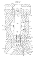
- a generally tubular, including flared or tapered, endovascular graft 10 having a superior end 12 and inferior end 14 is implanted in a body vessel 30 across an aneurysm sac 32 with the superior end 12 secured above the aneurysm and the inferior end 14 secured below the aneurysm.
- the endovascular graft 10 has sensors 16 attached external the superior 12 and inferior 14 ends, Additionally, the endovascular graft 10 has sensors 18 attached internal the superior 12 and inferior 14 ends. Furthermore, the endovascular graft 10 has sensors 20 attached external the midsection.
- the endovascular graft 10 has a transmitter 22 and power source 24 attached external the graft material in the area where the graft traverses the aneurysm sac 32.
- the sensors 16,18, 20 measure pertinent parameters inside and outside the endovascular graft and the power source 24 provides power for the transmitter 22 which transmits the measurements to a receiver (not shown) located outside the patient's body.
- the transmitter 22, power source 24 and receiver may be of any type known in the art of surgical implants or other systems utilizing miniaturized power sources and transmitters.
- the power source 24 and transmitter 22, for example, may be of the type used in pacemaker technology or passive power sources such as ultrasonically chargeable capacitors.
- the sensors 16, 18, 20 shown in FIG. 1 may measure pressure. These measurements may be used as an aid in endovascular graft 10 placement or to identify anomalies that occur after endovascular graft 10 implantation before aneurysm rupture occurs.
- the sensors 16 external the superior 12 and inferior 14 ends of the endovascular graft 10 may be used to detect changes in pressure resulting from blood leakage between the endovascular graft 10 and the vessel wall 30, an cndoleak resulting from an inadequate seal between them. It is contemplated that sensors 17 may be located around the entire circumference of the superior 12 and inferior 14 ends of the endovascular graft 10, thereby allowing the exact location of an endoleak to be determined.
- the sensors 18 internal the superior 12 and inferior 14 ends of the endovascular graft 10 may be used to measure inlet and outlet pressure of blood flow therethrough.
- a pressure drop indicates an anomaly such as kinking of the endovascular graft 10 or endoleak due to fabric tears or graft material disintegration.
- sensors 19 may be located around the entire circumference of the superior 12 and inferior 14 ends of the endovascular graft 10.
- the sensors 20 external the midsection of the endovascular graft 10 may be used to measure pressure resulting from blood flow into the aneurysm sac 32, an indication that endoleak has occurred and there is a risk of aneurysm rupture. Because the sensors 20 are located in the area of the aneurysm sac 32, there are multiple sensors 20 disbursed over the graft material outer wall since local thrombus or calcification may shield one or more of the sensors 20 from blood pressure and render their measurements erroneous.
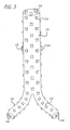
- FIG. 2 the embodiment of the invention shown in FIG. 1 is applied to a bifurcated endovascular graft 110 of the type known within the art.
- the bifurcated endovascular graft 110 is assembled in-vivo from a tubular trunk portion 40 and two limb portions 50 (only one is shown).
- the bifurcated endovascular graft 110 is implanted in a body vessel 30 across an aneurysm sac 32 and into the contra-lateral 34 and ipsi-lateral 36 arteries using methods known within the art.
- the trunk portion 40 has a superior end 42 adapted to be secured above the aneurysm and an inferior end 44 adapted to accept the limb portions 50.
- the trunk portion 40 has a transmitter 22, power source 24, and sensors 16, 17, 18, 19, 20 similar to those described with reference to FIG. 1 .
- Each limb portion 50 has a superior end 52 adapted to mate with the trunk portion 40 inferior end 44 and an inferior end 54 adapted to be secured to the ipsi-lateral 34 or contra-lateral 36 iliac artery.
- Each limb portion 50 also has a transmitter 122, power source 124, and sensors 116, 117, 118, 119, 120 similar to those described with reference to FIG. 1 .
- the transmitter 122 and power source 124 facilitate transmission of parameters measured by the sensors 116, 117, 118, 119, 120 to a receiver (not shown) outside the patient's body.
- the functions of some of the sensors are slightly different than those previously described with reference to a tubular endovascular graft.
- the sensors 116 external the superior 52 end of a limb portion 50 may be used to detect pressure changes resulting from blood leakage between the limb portion 50 and the trunk portion 40, an endoleak resulting from an inadequate seal between the limb portion 50 superior end 52 and trunk portion 40 inferior end 14.
- the sensors 116 external the inferior 54 end of a limb portion 50 may be used to detect pressure changes resulting from blood leakage between the limb portion 50 and the ipsi-lateral 34 or contra-lateral 36 iliac artery wall, an endoleak resulting from an inadequate seal between the limb portion 50 inferior end 54 and vessel 30.
- the sensors 118 internal the superior 52 and inferior 54 ends of a limb portion 50 may be used to measure inlet and outlet pressure of blood flow therethrough, with a pressure drop indicating an anomaly such as kinking of the limb portion 50 or endoleak due to fabric tears or graft material disintegration.
- the sensors 120 external the midsection of the limb portion 50 may be used to measure pressure resulting from blood flow between the limb portion 50 and the wall of the ipsi-lateral 34 or contra-lateral 36 iliac artery, an indication that endoleak has occurred due to inadequate mating of the limb portion 50 superior end 52 and the trunk portion 40 inferior end 44.
- the sensors of the invention shown in FIGS. 1 and 2 may measure temperature. Differences in temperature may identify "hot spots" associated with infection, inflammation, thrombus formation or other anomalies that indicate an increased risk for aneurysm rupture. Methods known in the art of pathology and physiology may be used to relate temperature to changes in the vessel walls within which the endovascular graft is implanted.
- the sensors of the invention shown in FIGS. 1 and 2 may detect blood flow by measuring oxygen or other constituents, such as enzymes, proteins and nutrients, which are altered by the presence of blood flow.
- Such sensors may allow detection of minute blood flow, often missed by conventional imaging modalities, and, therefore, allow endoleaks to be detected earlier.
- One method is to obtain a baseline of the constituents upon implantation of the endovascular graft. Thereafter, changes in the amount of the measured constituents may be used to identify anomalies.
- the sensors of the invention shown in FIGS. 1 and 2 may measure electrical potential. Changes in electrical potential may identify areas of the patient's vasculature that are at risk for thrombus formation.
- FIGS. 1 and 2 may be varied to meet the requirements of the individual patient. It is further contemplated that sensors which measure different pertinent parameters may be used together. Moreover, it is contemplated that the invention shown in FIGS. 1 and 2 may be utilized in any type of endovascular graft implant known in the art.
- miniature sensors 216,218 are arranged as an array covering the interior and exterior of the surface of the endovascular graft 210.
- the array of sensors 216,218 provides a complete profile of pertinent parameters over the entire surface of the endovascular graft and, therefore, facilitates better identification of anomalies.
- the transmitter 222, power source 224 and external receiver (not shown) allow the measured parameters to be received and monitored outside the patient's body.
- the array of sensors 216,218 may spiral around the graft material in between the weaves of fabric and consist of a strip of sensors, continuous strip of wire or other apparatus known in the art.
- the location and number of transmitters, power sources and sensors shown in FIG. 3 may be varied to meet the requirements of the individual patient. It is further contemplated that the array of sensors 216,218 may contain sensors capable of measuring pressure, temperature, blood flow, electrical potential, or any combination thereof. Moreover, it is contemplated that the example shown in FIG. 3 may be utilized in any type of endovascular graft implant known in the art.
Description
- This invention relates to the treatment of body lumens and, more particularly, to the endovascular placement of a prosthetic graft within vasculature for the purpose of repairing the same.
- Ruptured abdominal aortic aneurysms (AAA) are a leading cause of death in the United States. Treatment options to repair AAA include conventional open surgery and implantation of an endovascular graft. Conventional open surgical repair of AAA involves major abdominal surgery with associated high rates of morbidity. Endovascular grafts have been developed to endoluminally bypass abdominal aortic aneurysms through minimally invasive surgery. Many patients that are unacceptable surgical risks for open repairs are eligible for endovascular graft implantation. Deployment of transfemoral, endovascular grafts to treat AAA is appealing for many reasons: avoidance of an abdominal incision, lack of aortic cross clamping, the potential for regional anesthesia, and a shortened hospital stay.
- Untreated AAA has been shown to continue to expand until rupture, with an associated high mortality rate. Implantation of endovascular grafts have also been associated with high complication rates, including perioperative death, conversion to open repair, the need for further intervention, the need for hemodialysis, a failure to cure the AAA, and wound complications.
- The inability to obtain or maintain a secure seal between the vessel wall and the endovascular graft is a complication unique to endovascular aneurysm exclusion. Because the term "leak" has been associated with aneurysm rupture following conventional surgery, the term "endoleak" has been proposed as a more definitive description of this complication. It is believed that persistent endoleaks result in continued aneurysm expansion, which may eventually lead to aneurysm rupture. Aneurysms that have been successfully excluded have shown a tendency towards a reduction in aneurysm diameter. Failure to properly exclude the aneurysm from systemic arterial blood pressure keeps the patient at risk of impending rupture. Endoleaks have been classified according to the source of the leaks. Current classifications of endoleaks include four categories. Type I endoleaks are "perigraft" or "graft-related" leaks that involve a persistent channel of blood flow due to inadequate or ineffective sealing at the ends of the endovascular graft, or between overlapping components of a modular system. Type II endoleaks are retrograde flow into the aneurysm sac from patent lumbar arteries, the inferior mesenteric artery, or other collateral vessels. Type III endoleaks result from fabric tears, graft disconnection, or graft disintegration. Finally, Type IV endoleaks are flow through the graft fabric associated with graft wall porosity or permeability. Preoperative patent side branches are not a good predictor of postoperative endoleaks.
- A number of reported cases of aneurysm rupture following implantation of an endovascular graft have been reported. Some of the ruptures occurred in patients without a documented endoleak.
- A number of studies have focused on measurement of pressure within the aneurysm sac following implantation of an endovascular graft, both in the human patient, an animal model, or an in vitro model. Properly implanted endovascular grafts have been shown to reduce the pressure within the aneurysm sac while an endoleak, with or without detectable blood flow, continues to pressurize the sac at pressures equivalent to the systemic arterial pressure. Animal studies utilizing a predictable rupturing aneurysm model have shown that non-excluded aneurysms will rupture. Thrombosed aneurysm sacs may still receive pressurization from a sealed endoleak and this continued pressurization keeps the aneurysm at risk for rupture.
- Current methods of patient follow-up include arteriography, contrast-enhanced spiral computed tomography (CT), duplex ultrasonography, abdominal X-ray, and intravascular ultrasound. All of these methods are costly and involve invasive procedures that have associated morbidity. None of the imaging methods are completely successful in detecting endoleaks. Therefore, the potential exists for an endoleak to go undetected until eventual rupture. An increase in aneurysm diameter is detectable, and should be considered an indication of endoleak. To avoid aneurysm rupture an increase in aneurysm diameter must be detected in a timely fashion to identify patients in need of corrective surgical procedures.
- An endovascular graft with the ability to measure pressure within the aneurysm sac and provide feedback to the physician could identify those patients with persistent pressurization of their aneurysm, and subsequent risk of rupture.
- Some physicians are advocating that the follow-up examinations of AAA patients focus on pressure measurements, but that this is not currently clinically feasible.
- From
EP 0 897 690 A1 a device is known for introduction into a human or animal body, specifically to be positioned in an aneurysmal sac in an artery between the wall of the artery and the wall of an endoprosthesis, comprising at least a pressure sensor and a transponder for wireless transmitting data available from the pressure sensor. - There exists a need for an endovascular graft that facilitates non-invasive measurement of pressure, as well as other pertinent parameters, within the aneurysm sac and along the endovascular graft itself as a means for identifying patients at risk for aneurysm rupture after the endovascular graft is implanted. The present invention addresses these and other needs.
- The invention pertains to a modular endoluminal prosthesis according to claim 1. Briefly and in general terms, the present invention is embodied in an endovascular graft with sensors attached thereto. The device will have the ability to be delivered endovascularly and measure pertinent parameters within the excluded AAA. The endovascular graft would have the ability to transmit data about intra- sac parameters to an external monitoring device. Patient follow-up would be less costly (conducted in the physician office), non-invasive, and more accurate, allowing prompt intervention in those patients most at risk for acute rupture. The invention would also allow for more frequent patient follow-up, increasing the potential to diagnose and treat aneurysms at risk before acute rupture. The invention is applicable to all applications of endovascular grafts to treat aneurysmal segments of blood vessels. It is contemplated that the invention may be used with all shapes of endovascular grafts known within the art.
- In one embodiment, sensors are attached to the endovascular graft at the superior end, inferior end and midsection. Measurements of pertinent parameters and comparison of those measurements may allow early identification of areas of the patient's vasculature at risk for aneurysm rupture, thrombus formation, infection, inflamation or other anomalies without the need for invasive procedures.
- In another embodiment, a pattern of sensors are attached to the endovascular graft such that they cover the interior and exterior of the graft. The pattern of sensors allow a complete profile of pertinent parameters along the endovascular graft to be obtained. Such a profile may provide more accurate identification of anomalies.
- Sensors with pressure measurement capability may be used to detect pressure changes external the endovascular graft, in the aneurysm sac or in blood flow through the interior of the endovascular graft indicative of graft failure, graft kinking, or endoleak due to an inadequate seal between the endovascular graft and the vasculature. Sensors with temperature measurement capability may be used to detect temperature differentials associated with "hot spots" related to inflamation, infection or thrombus formation in the vessel. Sensors with the capability to measure oxygen and other blood constituents such as enzymes, proteins, and nutrients, may be used to detect minute blood flow indicative of endoleak. Sensors with the capability to measure electrical potential may be used to detect differences in potential associated with areas of the vessel at risk for thrombus formation.
- An antenna or other data transmitter and a power source may be attached external the endovascular graft, allowing a physician or technician to monitor graft and vessel health without the need for an invasive procedure. The transmitter transmits measurements made by the sensors to a receiver located outside the patient's body.
- Other features and advantages of the present invention will become apparent from the following detailed description taken in conjunction with the accompanying drawings, which illustrate, by way of example, the principles of the invention.
-
-
FIG. 1 is a partial cross-sectional view of an example showing a generally tubular cndovascular graft implanted across an aneurysm sac; -
FIG. 2 is a partial cross-sectional view of an embodiment of the invention showing a partially assembled bifurcated endovascular graft; and -
FIGS. 3 is a perspective view of another example showing a bifurcated endovascular graft having an array of sensors on the external and internal surfaces of the graft material. - As shown in the exemplary drawings and for purposes of illustration, the invention is embodied in a prosthetic endovascular graft implant having the ability to measure pertinent parameters inside and outside the graft material and transmit the measurements to a receiver located external the patient within whom the endovascular graft is implanted. In one aspect, the invention includes a graft with sensors mounted on the external and internal surface that measure parameters such as pressure, temperature or voltage. In another aspect the invention includes a transmitter and energy source which facilitate transmission of parameters measured by the sensors to a receiver located outside the patient's body.
- Referring to
FIG. 1 , an example is shown in which a generally tubular, including flared or tapered,endovascular graft 10 having asuperior end 12 andinferior end 14 is implanted in abody vessel 30 across ananeurysm sac 32 with thesuperior end 12 secured above the aneurysm and theinferior end 14 secured below the aneurysm. Theendovascular graft 10 hassensors 16 attached external the superior 12 and inferior 14 ends, Additionally, theendovascular graft 10 hassensors 18 attached internal the superior 12 and inferior 14 ends. Furthermore, theendovascular graft 10 hassensors 20 attached external the midsection. Moreover, theendovascular graft 10 has atransmitter 22 andpower source 24 attached external the graft material in the area where the graft traverses theaneurysm sac 32. Thesensors power source 24 provides power for thetransmitter 22 which transmits the measurements to a receiver (not shown) located outside the patient's body. - The
transmitter 22,power source 24 and receiver (not shown) may be of any type known in the art of surgical implants or other systems utilizing miniaturized power sources and transmitters. Thepower source 24 andtransmitter 22, for example, may be of the type used in pacemaker technology or passive power sources such as ultrasonically chargeable capacitors. - The
sensors FIG. 1 may measure pressure. These measurements may be used as an aid inendovascular graft 10 placement or to identify anomalies that occur after endovasculargraft 10 implantation before aneurysm rupture occurs. - The
sensors 16 external the superior 12 and inferior 14 ends of theendovascular graft 10 may be used to detect changes in pressure resulting from blood leakage between theendovascular graft 10 and thevessel wall 30, an cndoleak resulting from an inadequate seal between them. It is contemplated thatsensors 17 may be located around the entire circumference of the superior 12 and inferior 14 ends of theendovascular graft 10, thereby allowing the exact location of an endoleak to be determined. - The
sensors 18 internal the superior 12 and inferior 14 ends of theendovascular graft 10 may be used to measure inlet and outlet pressure of blood flow therethrough. A pressure drop indicates an anomaly such as kinking of theendovascular graft 10 or endoleak due to fabric tears or graft material disintegration. It is also contemplated thatsensors 19 may be located around the entire circumference of the superior 12 and inferior 14 ends of theendovascular graft 10. - The
sensors 20 external the midsection of theendovascular graft 10 may be used to measure pressure resulting from blood flow into theaneurysm sac 32, an indication that endoleak has occurred and there is a risk of aneurysm rupture. Because thesensors 20 are located in the area of theaneurysm sac 32, there aremultiple sensors 20 disbursed over the graft material outer wall since local thrombus or calcification may shield one or more of thesensors 20 from blood pressure and render their measurements erroneous. - Referring to
FIG. 2 , the embodiment of the invention shown inFIG. 1 is applied to a bifurcatedendovascular graft 110 of the type known within the art. The bifurcatedendovascular graft 110 is assembled in-vivo from atubular trunk portion 40 and two limb portions 50 (only one is shown). The bifurcatedendovascular graft 110 is implanted in abody vessel 30 across ananeurysm sac 32 and into the contra-lateral 34 and ipsi-lateral 36 arteries using methods known within the art. - The
trunk portion 40 has asuperior end 42 adapted to be secured above the aneurysm and aninferior end 44 adapted to accept thelimb portions 50. Thetrunk portion 40 has atransmitter 22,power source 24, andsensors FIG. 1 . - Each
limb portion 50 has asuperior end 52 adapted to mate with thetrunk portion 40inferior end 44 and aninferior end 54 adapted to be secured to the ipsi-lateral 34 or contra-lateral 36 iliac artery. Eachlimb portion 50 also has atransmitter 122,power source 124, andsensors FIG. 1 . Thetransmitter 122 andpower source 124 facilitate transmission of parameters measured by thesensors - The functions of some of the sensors are slightly different than those previously described with reference to a tubular endovascular graft. The
sensors 116 external the superior 52 end of alimb portion 50 may be used to detect pressure changes resulting from blood leakage between thelimb portion 50 and thetrunk portion 40, an endoleak resulting from an inadequate seal between thelimb portion 50superior end 52 andtrunk portion 40inferior end 14. Thesensors 116 external the inferior 54 end of alimb portion 50 may be used to detect pressure changes resulting from blood leakage between thelimb portion 50 and the ipsi-lateral 34 or contra-lateral 36 iliac artery wall, an endoleak resulting from an inadequate seal between thelimb portion 50inferior end 54 andvessel 30. Thesensors 118 internal the superior 52 and inferior 54 ends of alimb portion 50 may be used to measure inlet and outlet pressure of blood flow therethrough, with a pressure drop indicating an anomaly such as kinking of thelimb portion 50 or endoleak due to fabric tears or graft material disintegration. Thesensors 120 external the midsection of thelimb portion 50 may be used to measure pressure resulting from blood flow between thelimb portion 50 and the wall of the ipsi-lateral 34 or contra-lateral 36 iliac artery, an indication that endoleak has occurred due to inadequate mating of thelimb portion 50superior end 52 and thetrunk portion 40inferior end 44. - Alternatively, the sensors of the invention shown in
FIGS. 1 and2 may measure temperature. Differences in temperature may identify "hot spots" associated with infection, inflammation, thrombus formation or other anomalies that indicate an increased risk for aneurysm rupture. Methods known in the art of pathology and physiology may be used to relate temperature to changes in the vessel walls within which the endovascular graft is implanted. - Alternatively, the sensors of the invention shown in
FIGS. 1 and2 may detect blood flow by measuring oxygen or other constituents, such as enzymes, proteins and nutrients, which are altered by the presence of blood flow. Such sensors may allow detection of minute blood flow, often missed by conventional imaging modalities, and, therefore, allow endoleaks to be detected earlier. One method is to obtain a baseline of the constituents upon implantation of the endovascular graft. Thereafter, changes in the amount of the measured constituents may be used to identify anomalies. - Alternatively, the sensors of the invention shown in
FIGS. 1 and2 may measure electrical potential. Changes in electrical potential may identify areas of the patient's vasculature that are at risk for thrombus formation. - It is contemplated that the number of transmitters, power sources and sensors shown in
FIGS. 1 and2 may be varied to meet the requirements of the individual patient. It is further contemplated that sensors which measure different pertinent parameters may be used together. Moreover, it is contemplated that the invention shown inFIGS. 1 and2 may be utilized in any type of endovascular graft implant known in the art. - Referring to
FIG. 3 , another example is shown in which miniature sensors 216,218 are arranged as an array covering the interior and exterior of the surface of theendovascular graft 210. The array of sensors 216,218 provides a complete profile of pertinent parameters over the entire surface of the endovascular graft and, therefore, facilitates better identification of anomalies. Thetransmitter 222,power source 224 and external receiver (not shown) allow the measured parameters to be received and monitored outside the patient's body. The array of sensors 216,218 may spiral around the graft material in between the weaves of fabric and consist of a strip of sensors, continuous strip of wire or other apparatus known in the art. - It is contemplated that the location and number of transmitters, power sources and sensors shown in
FIG. 3 may be varied to meet the requirements of the individual patient. It is further contemplated that the array of sensors 216,218 may contain sensors capable of measuring pressure, temperature, blood flow, electrical potential, or any combination thereof. Moreover, it is contemplated that the example shown inFIG. 3 may be utilized in any type of endovascular graft implant known in the art.
Claims (27)
- A modular endoluminal prosthesis for repairing vasculature in an area of an aneurysm sac, comprising:a first endovascular graft component (40);a second endovascular graft component (50) having a superior end (52) adapted to mate in-vivo with an inferior end (44) of the first endovascular graft component (40), the second cndovascular graft component (50) having one or more sensors (116) attached at the superior end (52) of the second endovascular graft component (50), wherein the sensors (116) of the second endovascular graft component (50) detect parameters in the aneurysm sac relating to an endoleak between the first endovascular graft component (40) and the second endovascular graft component (50).
- The prosthesis of claim 1, further comprising:one or more power sources (24, 124) attached to external surfaces of the first andsecond endovascular graft components (40, 50); andone or more transmitting devices (22, 122) attached to the first and second endovascular graft components (40, 50), each transmitting device (22, 122) capable of transmitting signals containing the parameters measured by one or more sensors (116) to a location outside a patient's body.
- The prosthesis of claim 1, the first endovascular graft component (40) further comprising one or more sensors (16) attached thereto.
- The prosthesis of claim 2, further comprising one or more receiving devices located outside a patient's body, each receiving device capable of receiving signals transmitted by one or more transmitters (22, 122).
- The prosthesis of claim 1, wherein one of the first and second endovascular graft components (40, 50) is generally tubular and each have a superior end, an inferior end and a midsection.
- The prosthesis of claim 1, wherein at least one sensor (16, 116) is located on an internal surface of one of the first and second endovascular graft components (40, 50).
- The prosthesis of claim 1, wherein sensors (16, 116) cover substantially a circumferential area of an internal surface of one of the first and second endovascular graft components (40, 50).
- The prosthesis of claim 1, wherein at least one sensor (16, 116) is located on an external surface of one of the first and second endovascular graft components (40, 50).
- The prosthesis of claim 1, wherein sensors (16, 116) cover substantially a circumferential area of an external surface of one of the first and second endovascular graft components (40, 50).
- The prosthesis of claim 1, wherein one or more sensors (16, 116) are located on an external surface of one or more of the endovascular graft components (40, 50) at a midsection thereof.
- The prosthesis of claim 2, wherein each power source (24, 124) is attached to a midsection of one of the first and second endovascular graft components (40, 50).
- The prosthesis of claim 2, wherein each transmitter (22, 122) is attached to a midsection of one of the first and second endovascular graft components (40, 50).
- The prosthesis of claim 1, wherein the modular endoluminal prosthesis has a trunk portion (40) and two or more limb portions (50).
- The prosthesis of claim 13, wherein at least one sensor (16) is located on an internal surface of the first endovascular graft component (40).
- The prosthesis of claim 13, wherein sensors (16) cover substantially a circumferential area of an internal surface of the first endovascular graft component (40).
- The prosthesis of claim 13, wherein at least one sensor (116) is located on an external surface of each limb portion (50).
- The prosthesis of claim 13, wherein sensors (16) cover substantially a circumferential area of an external surface of the modular endoluminal prosthesis at superior and inferior ends of each limb portion (50).
- The prosthesis of claim 13, wherein one or more sensors (16) are located external the first endovascular graft component (40) at a midsection of each limb portion (50).
- The prosthesis of claim 1, wherein one or more of the sensors (16, 116) measure pressure.
- The prosthesis of claim 1, wherein one or more of the sensors (16, 116) measure temperature.
- The prosthesis of claim 1, wherein one or more of the sensors (16, 166) measure a constituent altered by the presence of minute amounts of blood flow.
- The prosthesis of claim 21, wherein the constituent measured is oxygen.
- The prosthesis of claim 21, wherein the constituent measured is an enzyme.
- The prosthesis of claim 21, wherein the constituent measured is a protein.
- The prosthesis of claim 21, wherein the constituent measured is a nutrient.
- The prosthesis of claim 1, wherein one or more of the sensors (16, 116) measure electrical potential.
- The prosthesis of claim 1, wherein one or more of the sensors (16, 116) measure a parameter related to the attachment between the first and second endovascular graft components (40, 50).
Applications Claiming Priority (3)
| Application Number | Priority Date | Filing Date | Title |
|---|---|---|---|
| US165200 | 2002-06-07 | ||
| US10/165,200 US7025778B2 (en) | 2002-06-07 | 2002-06-07 | Endovascular graft with pressure, temperature, flow and voltage sensors |
| PCT/US2003/017662 WO2003103542A1 (en) | 2002-06-07 | 2003-06-06 | Endoprosthesis having pressure, temperature, and flow sensors |
Publications (3)
| Publication Number | Publication Date |
|---|---|
| EP1511446A1 EP1511446A1 (en) | 2005-03-09 |
| EP1511446A4 EP1511446A4 (en) | 2009-02-11 |
| EP1511446B1 true EP1511446B1 (en) | 2012-08-01 |
Family
ID=29710383
Family Applications (1)
| Application Number | Title | Priority Date | Filing Date |
|---|---|---|---|
| EP03734408A Expired - Fee Related EP1511446B1 (en) | 2002-06-07 | 2003-06-06 | Endoprosthesis having pressure, temperature, and flow sensors |
Country Status (3)
| Country | Link |
|---|---|
| US (2) | US7025778B2 (en) |
| EP (1) | EP1511446B1 (en) |
| WO (1) | WO2003103542A1 (en) |
Families Citing this family (35)
| Publication number | Priority date | Publication date | Assignee | Title |
|---|---|---|---|---|
| US7147661B2 (en) | 2001-12-20 | 2006-12-12 | Boston Scientific Santa Rosa Corp. | Radially expandable stent |
| US7399313B2 (en) * | 2002-06-07 | 2008-07-15 | Brown Peter S | Endovascular graft with separable sensors |
| US7261733B1 (en) * | 2002-06-07 | 2007-08-28 | Endovascular Technologies, Inc. | Endovascular graft with sensors design and attachment methods |
| US7488345B2 (en) * | 2002-06-07 | 2009-02-10 | Endovascular Technologies, Inc. | Endovascular graft with pressor and attachment methods |
| US20040210118A1 (en) * | 2003-04-18 | 2004-10-21 | Michel Letort | In situ detection of endoleak and endotension |
| US8086323B2 (en) * | 2003-09-23 | 2011-12-27 | Medtronic Minimed, Inc. | Implantable multi-parameter sensing system and method |
| US20050065592A1 (en) * | 2003-09-23 | 2005-03-24 | Asher Holzer | System and method of aneurism monitoring and treatment |
| US7918800B1 (en) | 2004-10-08 | 2011-04-05 | Endovascular Technologies, Inc. | Aneurysm sensing devices and delivery systems |
| EP1847025A2 (en) * | 2005-01-20 | 2007-10-24 | BAE SYSTEMS Information and Electronic Systems Integration Inc. | Microradio design, manufacturing method and applications for the use of microradios |
| CA2598178A1 (en) * | 2005-02-16 | 2006-08-24 | Transoma Medical, Inc. | Impedance based sensor for monitoring leakage in abdominal aortic aneurism stent graft |
| CA2600613C (en) * | 2005-03-29 | 2016-10-25 | Martin Roche | Body parameter detecting sensor and method for detecting body parameters |
| US11457813B2 (en) | 2005-03-29 | 2022-10-04 | Martin W. Roche | Method for detecting body parameters |
| EP2046242A4 (en) * | 2006-07-07 | 2010-08-25 | Endotronix Inc | Methods and systems for monitoring an endoprosthetic implant |
| FR2905260B1 (en) * | 2006-09-04 | 2010-06-04 | Univ Paris Curie | ENDOPROTHESIS AND METHOD FOR PRODUCING A STENT. |
| US7677107B2 (en) * | 2007-07-03 | 2010-03-16 | Endotronix, Inc. | Wireless pressure sensor and method for fabricating wireless pressure sensor for integration with an implantable device |
| US20090287120A1 (en) | 2007-12-18 | 2009-11-19 | Searete Llc, A Limited Liability Corporation Of The State Of Delaware | Circulatory monitoring systems and methods |
| US8636670B2 (en) | 2008-05-13 | 2014-01-28 | The Invention Science Fund I, Llc | Circulatory monitoring systems and methods |
| US9717896B2 (en) | 2007-12-18 | 2017-08-01 | Gearbox, Llc | Treatment indications informed by a priori implant information |
| US9314584B1 (en) | 2011-06-27 | 2016-04-19 | Bayer Healthcare Llc | Method and apparatus for fractional flow reserve measurements |
| US10674966B2 (en) * | 2012-12-11 | 2020-06-09 | Covidien Lp | Systems for diagnosing and/or treating medical conditions |
| WO2014100795A1 (en) | 2012-12-21 | 2014-06-26 | Hunter William L | Stent graft monitoring assembly and method of use thereof |
| US9427305B2 (en) | 2013-01-24 | 2016-08-30 | GraftWorx, LLC | Method and apparatus for measuring flow through a lumen |
| US9757591B2 (en) | 2013-02-11 | 2017-09-12 | Bayer Healthcare Llc | Methods and systems for monitoring an automated infusion system |
| SG10201707624TA (en) * | 2013-03-15 | 2017-11-29 | William L Hunter | Stent monitoring assembly and method of use thereof |
| WO2015200718A1 (en) | 2014-06-25 | 2015-12-30 | Hunter William L | Devices, systems and methods for using and monitoring tubes in body passageways |
| DE102015101382B4 (en) * | 2015-01-30 | 2017-03-09 | Infineon Technologies Ag | Implantable vascular fluid sensor |
| US9924905B2 (en) | 2015-03-09 | 2018-03-27 | Graftworx, Inc. | Sensor position on a prosthesis for detection of a stenosis |
| US10758386B2 (en) | 2015-03-11 | 2020-09-01 | Board Of Regents Of The University Of Nebraska | Automated retrievable hemorrhage control system |
| US20190209743A1 (en) * | 2016-06-27 | 2019-07-11 | University Of Iowa Research Foundation | Magnetically-activated coating for treating biofilms, and associated systems and methods |
| CA3030857C (en) | 2016-07-14 | 2023-12-19 | The Board Of Regents Of The University Of Texas System | Methods, apparatuses, and systems for inductive heating of foreign metallic implants |
| WO2018049412A1 (en) | 2016-09-12 | 2018-03-15 | Graftworx, Inc. | Wearable device with multimodal diagnostics |
| CA3053497A1 (en) | 2017-02-24 | 2018-08-30 | Endotronix, Inc. | Wireless sensor reader assembly |
| US11615257B2 (en) | 2017-02-24 | 2023-03-28 | Endotronix, Inc. | Method for communicating with implant devices |
| JP2022525788A (en) | 2019-03-20 | 2022-05-19 | インキュベート メディカル テクノロジーズ、 エルエルシー | Aortic dissection implant |
| CN110196117A (en) * | 2019-05-15 | 2019-09-03 | 长飞光纤光缆股份有限公司 | A kind of two-parameter pre-calibration insertion type probe |
Family Cites Families (83)
| Publication number | Priority date | Publication date | Assignee | Title |
|---|---|---|---|---|
| US2634721A (en) * | 1951-05-19 | 1953-04-14 | Gen Precision Lab Inc | Pressure transducer |
| US3240207A (en) | 1963-05-31 | 1966-03-15 | North American Aviation Inc | Pressure sensor |
| US3888708A (en) * | 1972-02-17 | 1975-06-10 | Kensall D Wise | Method for forming regions of predetermined thickness in silicon |
| GR77132B (en) | 1982-03-25 | 1984-09-07 | Coats Ltd J & P | |
| US4732874A (en) * | 1986-10-15 | 1988-03-22 | Delco Electronics Corporation | Removing metal precipitates from semiconductor devices |
| US4815472A (en) | 1987-06-01 | 1989-03-28 | The Regents Of The University Of Michigan | Multipoint pressure-sensing catheter system |
| US5013396A (en) | 1987-06-01 | 1991-05-07 | The Regents Of The University Of Michigan | Method of making an ultraminiature pressure sensor |
| US4881410A (en) | 1987-06-01 | 1989-11-21 | The Regents Of The University Of Michigan | Ultraminiature pressure sensor and method of making same |
| US5207103A (en) | 1987-06-01 | 1993-05-04 | Wise Kensall D | Ultraminiature single-crystal sensor with movable member |
| US5113868A (en) | 1987-06-01 | 1992-05-19 | The Regents Of The University Of Michigan | Ultraminiature pressure sensor with addressable read-out circuit |
| US4834101A (en) | 1987-06-26 | 1989-05-30 | The University Of Michigan | Catheter-type electrochemical sensors |
| US5343064A (en) * | 1988-03-18 | 1994-08-30 | Spangler Leland J | Fully integrated single-crystal silicon-on-insulator process, sensors and circuits |
| US4846191A (en) | 1988-05-27 | 1989-07-11 | Data Sciences, Inc. | Device for chronic measurement of internal body pressure |
| US5000049A (en) * | 1988-08-02 | 1991-03-19 | Cooper Robert P | Pressure gauge for medical applications |
| US5055838A (en) | 1988-12-09 | 1991-10-08 | The Regents Of The University Of Michigan | Silicon tactile imaging array and method of making same |
| US4953387A (en) | 1989-07-31 | 1990-09-04 | The Regents Of The University Of Michigan | Ultrathin-film gas detector |
| US5314458A (en) * | 1990-06-01 | 1994-05-24 | University Of Michigan | Single channel microstimulator |
| GB9012753D0 (en) * | 1990-06-08 | 1990-08-01 | Amp Gmbh | Terminal housing with integral carrier strip which produces no loose piece slugs |
| US5578071A (en) | 1990-06-11 | 1996-11-26 | Parodi; Juan C. | Aortic graft |
| US5213999A (en) * | 1990-09-04 | 1993-05-25 | Delco Electronics Corporation | Method of metal filled trench buried contacts |
| US5059543A (en) | 1990-09-21 | 1991-10-22 | The Board Of Regents Acting For And On Behalf Of The University Of Michigan | Method of manufacturing thermopile infrared detector |
| US5100479A (en) | 1990-09-21 | 1992-03-31 | The Board Of Regents Acting For And On Behalf Of The University Of Michigan | Thermopile infrared detector with semiconductor supporting rim |
| US5250837A (en) * | 1991-05-17 | 1993-10-05 | Delco Electronics Corporation | Method for dielectrically isolating integrated circuits using doped oxide sidewalls |
| US5250461A (en) * | 1991-05-17 | 1993-10-05 | Delco Electronics Corporation | Method for dielectrically isolating integrated circuits using doped oxide sidewalls |
| US5262127A (en) * | 1992-02-12 | 1993-11-16 | The Regents Of The University Of Michigan | Solid state chemical micro-reservoirs |
| US5296255A (en) * | 1992-02-14 | 1994-03-22 | The Regents Of The University Of Michigan | In-situ monitoring, and growth of thin films by means of selected area CVD |
| US5377524A (en) | 1992-06-22 | 1995-01-03 | The Regents Of The University Of Michigan | Self-testing capacitive pressure transducer and method |
| US5306294A (en) | 1992-08-05 | 1994-04-26 | Ultrasonic Sensing And Monitoring Systems, Inc. | Stent construction of rolled configuration |
| US5427975A (en) | 1993-05-10 | 1995-06-27 | Delco Electronics Corporation | Method of micromachining an integrated sensor on the surface of a silicon wafer |
| KR970004922B1 (en) | 1993-07-27 | 1997-04-08 | 삼성전자 주식회사 | Wiring structure of high integrated semiconductor |
| US5417235A (en) * | 1993-07-28 | 1995-05-23 | Regents Of The University Of Michigan | Integrated microvalve structures with monolithic microflow controller |
| JP2641027B2 (en) | 1993-12-28 | 1997-08-13 | タスコ・ジャパン株式会社 | Pressure sensor device |
| EP0702221A3 (en) | 1994-09-14 | 1997-05-21 | Delco Electronics Corp | One-chip integrated sensor |
| US5547093A (en) | 1994-09-14 | 1996-08-20 | Delco Electronics Corporation | Method for forming a micromachine motion sensor |
| US5598847A (en) | 1994-12-28 | 1997-02-04 | Pacesetter, Inc. | Implantable flow sensor apparatus and method |
| US5683449A (en) * | 1995-02-24 | 1997-11-04 | Marcade; Jean Paul | Modular bifurcated intraluminal grafts and methods for delivering and assembling same |
| US5992769A (en) * | 1995-06-09 | 1999-11-30 | The Regents Of The University Of Michigan | Microchannel system for fluid delivery |
| US5663508A (en) * | 1995-08-07 | 1997-09-02 | Delco Electronics Corporation | Silicon flow sensor |
| US6140144A (en) * | 1996-08-08 | 2000-10-31 | Integrated Sensing Systems, Inc. | Method for packaging microsensors |
| US6136212A (en) * | 1996-08-12 | 2000-10-24 | The Regents Of The University Of Michigan | Polymer-based micromachining for microfluidic devices |
| US5706565A (en) * | 1996-09-03 | 1998-01-13 | Delco Electronics Corporation | Method for making an all-silicon capacitive pressure sensor |
| US5735887A (en) * | 1996-12-10 | 1998-04-07 | Exonix Corporation | Closed-loop, RF-coupled implanted medical device |
| ES2208963T3 (en) | 1997-01-03 | 2004-06-16 | Biosense, Inc. | PRESSURE SENSITIVE VASCULAR ENDOPROTESIS. |
| US5831162A (en) * | 1997-01-21 | 1998-11-03 | Delco Electronics Corporation | Silicon micromachined motion sensor and method of making |
| US6015387A (en) | 1997-03-20 | 2000-01-18 | Medivas, Llc | Implantation devices for monitoring and regulating blood flow |
| US5976994A (en) * | 1997-06-13 | 1999-11-02 | Regents Of The University Of Michigan | Method and system for locally annealing a microstructure formed on a substrate and device formed thereby |
| EP0897690B1 (en) | 1997-08-15 | 2013-04-24 | Academisch Ziekenhuis Leiden h.o.d.n. LUMC | Pressure sensor for use in an aneurysmal sac |
| US5936164A (en) | 1997-08-27 | 1999-08-10 | Delco Electronics Corporation | All-silicon capacitive pressure sensor |
| US6035714A (en) * | 1997-09-08 | 2000-03-14 | The Regents Of The University Of Michigan | Microelectromechanical capacitive accelerometer and method of making same |
| US6167757B1 (en) * | 1997-09-08 | 2001-01-02 | The Regents Of The University Of Michigan | Single-side microelectromechanical capacitive accelerometer and method of making same |
| US5915281A (en) | 1997-10-03 | 1999-06-22 | Delco Electronics Corporation | Silicon force and displacement sensor |
| US5807258A (en) * | 1997-10-14 | 1998-09-15 | Cimochowski; George E. | Ultrasonic sensors for monitoring the condition of a vascular graft |
| US6231516B1 (en) | 1997-10-14 | 2001-05-15 | Vacusense, Inc. | Endoluminal implant with therapeutic and diagnostic capability |
| US5967986A (en) * | 1997-11-25 | 1999-10-19 | Vascusense, Inc. | Endoluminal implant with fluid flow sensing capability |
| US6431175B1 (en) * | 1997-12-30 | 2002-08-13 | Remon Medical Technologies Ltd. | System and method for directing and monitoring radiation |
| US6140740A (en) * | 1997-12-30 | 2000-10-31 | Remon Medical Technologies, Ltd. | Piezoelectric transducer |
| US6237398B1 (en) * | 1997-12-30 | 2001-05-29 | Remon Medical Technologies, Ltd. | System and method for monitoring pressure, flow and constriction parameters of plumbing and blood vessels |
| US6198965B1 (en) * | 1997-12-30 | 2001-03-06 | Remon Medical Technologies, Ltd. | Acoustic telemetry system and method for monitoring a rejection reaction of a transplanted organ |
| US6239724B1 (en) * | 1997-12-30 | 2001-05-29 | Remon Medical Technologies, Ltd. | System and method for telemetrically providing intrabody spatial position |
| US6475170B1 (en) * | 1997-12-30 | 2002-11-05 | Remon Medical Technologies Ltd | Acoustic biosensor for monitoring physiological conditions in a body implantation site |
| US5932809A (en) | 1998-02-17 | 1999-08-03 | Delco Electronics Corporation | Sensor with silicon strain gage |
| US6062461A (en) * | 1998-06-03 | 2000-05-16 | Delphi Technologies, Inc. | Process for bonding micromachined wafers using solder |
| US5929497A (en) * | 1998-06-11 | 1999-07-27 | Delco Electronics Corporation | Batch processed multi-lead vacuum packaging for integrated sensors and circuits |
| US6109113A (en) | 1998-06-11 | 2000-08-29 | Delco Electronics Corp. | Silicon micromachined capacitive pressure sensor and method of manufacture |
| US6022756A (en) * | 1998-07-31 | 2000-02-08 | Delco Electronics Corp. | Metal diaphragm sensor with polysilicon sensing elements and methods therefor |
| AU3790700A (en) | 1998-11-25 | 2000-06-19 | Ball Semiconductor Inc. | Intraluminal monitoring system |
| US6232150B1 (en) * | 1998-12-03 | 2001-05-15 | The Regents Of The University Of Michigan | Process for making microstructures and microstructures made thereby |
| US6206835B1 (en) | 1999-03-24 | 2001-03-27 | The B. F. Goodrich Company | Remotely interrogated diagnostic implant device with electrically passive sensor |
| US6170488B1 (en) | 1999-03-24 | 2001-01-09 | The B. F. Goodrich Company | Acoustic-based remotely interrogated diagnostic implant device and system |
| US6092530A (en) * | 1999-03-24 | 2000-07-25 | The B.F. Goodrich Company | Remotely interrogated implant device with sensor for detecting accretion of biological matter |
| US6171253B1 (en) | 1999-05-04 | 2001-01-09 | Apex Medical, Inc. | Flat tube pressure sensor |
| US6300632B1 (en) * | 1999-10-14 | 2001-10-09 | The Regents Of The University Of Michigan | Uncooled infrared focal plane imager and microelectromechanical infrared detector for use therein |
| US6551303B1 (en) * | 1999-10-27 | 2003-04-22 | Atritech, Inc. | Barrier device for ostium of left atrial appendage |
| US6277078B1 (en) * | 1999-11-19 | 2001-08-21 | Remon Medical Technologies, Ltd. | System and method for monitoring a parameter associated with the performance of a heart |
| ATE255860T1 (en) * | 2000-03-03 | 2003-12-15 | Cook Inc | ENDOVASCULAR DEVICE WITH STENT |
| US6416474B1 (en) * | 2000-03-10 | 2002-07-09 | Ramon Medical Technologies Ltd. | Systems and methods for deploying a biosensor in conjunction with a prosthesis |
| US6840956B1 (en) * | 2000-03-10 | 2005-01-11 | Remon Medical Technologies Ltd | Systems and methods for deploying a biosensor with a stent graft |
| US6442413B1 (en) * | 2000-05-15 | 2002-08-27 | James H. Silver | Implantable sensor |
| US6764446B2 (en) | 2000-10-16 | 2004-07-20 | Remon Medical Technologies Ltd | Implantable pressure sensors and methods for making and using them |
| WO2002098296A1 (en) * | 2001-06-05 | 2002-12-12 | Apex Medical, Inc. | Pressure sensing endograft |
| US6702847B2 (en) * | 2001-06-29 | 2004-03-09 | Scimed Life Systems, Inc. | Endoluminal device with indicator member for remote detection of endoleaks and/or changes in device morphology |
| US6682490B2 (en) * | 2001-12-03 | 2004-01-27 | The Cleveland Clinic Foundation | Apparatus and method for monitoring a condition inside a body cavity |
| US20030125790A1 (en) * | 2001-12-27 | 2003-07-03 | Vitaly Fastovsky | Deployment device, system and method for medical implantation |
-
2002
- 2002-06-07 US US10/165,200 patent/US7025778B2/en not_active Expired - Fee Related
-
2003
- 2003-06-06 EP EP03734408A patent/EP1511446B1/en not_active Expired - Fee Related
- 2003-06-06 WO PCT/US2003/017662 patent/WO2003103542A1/en not_active Application Discontinuation
-
2006
- 2006-01-23 US US11/338,208 patent/US20060149347A1/en not_active Abandoned
Also Published As
| Publication number | Publication date |
|---|---|
| US20060149347A1 (en) | 2006-07-06 |
| US20030229388A1 (en) | 2003-12-11 |
| US7025778B2 (en) | 2006-04-11 |
| EP1511446A1 (en) | 2005-03-09 |
| WO2003103542A1 (en) | 2003-12-18 |
| EP1511446A4 (en) | 2009-02-11 |
Similar Documents
| Publication | Publication Date | Title |
|---|---|---|
| EP1511446B1 (en) | Endoprosthesis having pressure, temperature, and flow sensors | |
| US7261733B1 (en) | Endovascular graft with sensors design and attachment methods | |
| US7399313B2 (en) | Endovascular graft with separable sensors | |
| US20230284975A1 (en) | Method and apparatus for measuring flow through a lumen | |
| US20020183628A1 (en) | Pressure sensing endograft | |
| Ohki et al. | Initial results of wireless pressure sensing for endovascular aneurysm repair: the APEX Trial—Acute Pressure Measurement to Confirm Aneurysm Sac EXclusion | |
| EP1742594B1 (en) | Attachment method of an endovascular graft and a pressor | |
| US6743180B1 (en) | Pressure sensor for use in an artery | |
| JP2009542421A (en) | Method and system for monitoring an endoprosthesis implant | |
| US20220167922A1 (en) | Providing medical devices with sensing functionality | |
| EP3267878B1 (en) | Sensor position on a prosthesis for detection of a stenosis | |
| US20230346538A1 (en) | Providing medical devices with sensing functionality |
Legal Events
| Date | Code | Title | Description |
|---|---|---|---|
| PUAI | Public reference made under article 153(3) epc to a published international application that has entered the european phase |
Free format text: ORIGINAL CODE: 0009012 |
|
| 17P | Request for examination filed |
Effective date: 20041207 |
|
| AK | Designated contracting states |
Kind code of ref document: A1 Designated state(s): AT BE BG CH CY CZ DE DK EE ES FI FR GB GR HU IE IT LI LU MC NL PT RO SE SI SK TR |
|
| RBV | Designated contracting states (corrected) |
Designated state(s): DE FR GB IE |
|
| RIN1 | Information on inventor provided before grant (corrected) |
Inventor name: HAYASHI, REID Inventor name: CONCEMI, ALFRED |
|
| A4 | Supplementary search report drawn up and despatched |
Effective date: 20090113 |
|
| 17Q | First examination report despatched |
Effective date: 20090326 |
|
| REG | Reference to a national code |
Ref country code: DE Ref legal event code: R079 Ref document number: 60341670 Country of ref document: DE Free format text: PREVIOUS MAIN CLASS: A61F0002060000 Ipc: A61B0005070000 |
|
| GRAP | Despatch of communication of intention to grant a patent |
Free format text: ORIGINAL CODE: EPIDOSNIGR1 |
|
| RIC1 | Information provided on ipc code assigned before grant |
Ipc: A61F 2/06 20060101ALI20120126BHEP Ipc: A61B 5/07 20060101AFI20120126BHEP |
|
| GRAS | Grant fee paid |
Free format text: ORIGINAL CODE: EPIDOSNIGR3 |
|
| GRAA | (expected) grant |
Free format text: ORIGINAL CODE: 0009210 |
|
| AK | Designated contracting states |
Kind code of ref document: B1 Designated state(s): DE FR GB IE |
|
| REG | Reference to a national code |
Ref country code: GB Ref legal event code: FG4D |
|
| REG | Reference to a national code |
Ref country code: IE Ref legal event code: FG4D |
|
| REG | Reference to a national code |
Ref country code: DE Ref legal event code: R096 Ref document number: 60341670 Country of ref document: DE Effective date: 20120920 |
|
| PLBE | No opposition filed within time limit |
Free format text: ORIGINAL CODE: 0009261 |
|
| STAA | Information on the status of an ep patent application or granted ep patent |
Free format text: STATUS: NO OPPOSITION FILED WITHIN TIME LIMIT |
|
| 26N | No opposition filed |
Effective date: 20130503 |
|
| PGFP | Annual fee paid to national office [announced via postgrant information from national office to epo] |
Ref country code: DE Payment date: 20130529 Year of fee payment: 11 |
|
| REG | Reference to a national code |
Ref country code: DE Ref legal event code: R097 Ref document number: 60341670 Country of ref document: DE Effective date: 20130503 |
|
| GBPC | Gb: european patent ceased through non-payment of renewal fee |
Effective date: 20130606 |
|
| REG | Reference to a national code |
Ref country code: IE Ref legal event code: MM4A |
|
| REG | Reference to a national code |
Ref country code: FR Ref legal event code: ST Effective date: 20140228 |
|
| PG25 | Lapsed in a contracting state [announced via postgrant information from national office to epo] |
Ref country code: IE Free format text: LAPSE BECAUSE OF NON-PAYMENT OF DUE FEES Effective date: 20130606 Ref country code: GB Free format text: LAPSE BECAUSE OF NON-PAYMENT OF DUE FEES Effective date: 20130606 |
|
| PG25 | Lapsed in a contracting state [announced via postgrant information from national office to epo] |
Ref country code: FR Free format text: LAPSE BECAUSE OF NON-PAYMENT OF DUE FEES Effective date: 20130701 |
|
| REG | Reference to a national code |
Ref country code: DE Ref legal event code: R119 Ref document number: 60341670 Country of ref document: DE |
|
| REG | Reference to a national code |
Ref country code: DE Ref legal event code: R119 Ref document number: 60341670 Country of ref document: DE Effective date: 20150101 |
|
| PG25 | Lapsed in a contracting state [announced via postgrant information from national office to epo] |
Ref country code: DE Free format text: LAPSE BECAUSE OF NON-PAYMENT OF DUE FEES Effective date: 20150101 |