EP1510457A2 - Anti collision light for aircraft - Google Patents
Anti collision light for aircraft Download PDFInfo
- Publication number
- EP1510457A2 EP1510457A2 EP04024156A EP04024156A EP1510457A2 EP 1510457 A2 EP1510457 A2 EP 1510457A2 EP 04024156 A EP04024156 A EP 04024156A EP 04024156 A EP04024156 A EP 04024156A EP 1510457 A2 EP1510457 A2 EP 1510457A2
- Authority
- EP
- European Patent Office
- Prior art keywords
- plane
- planes
- diodes
- reflecting means
- anti collision
- Prior art date
- Legal status (The legal status is an assumption and is not a legal conclusion. Google has not performed a legal analysis and makes no representation as to the accuracy of the status listed.)
- Granted
Links
Images


Classifications
-
- B—PERFORMING OPERATIONS; TRANSPORTING
- B64—AIRCRAFT; AVIATION; COSMONAUTICS
- B64D—EQUIPMENT FOR FITTING IN OR TO AIRCRAFT; FLIGHT SUITS; PARACHUTES; ARRANGEMENTS OR MOUNTING OF POWER PLANTS OR PROPULSION TRANSMISSIONS IN AIRCRAFT
- B64D47/00—Equipment not otherwise provided for
- B64D47/02—Arrangements or adaptations of signal or lighting devices
- B64D47/06—Arrangements or adaptations of signal or lighting devices for indicating aircraft presence
-
- B—PERFORMING OPERATIONS; TRANSPORTING
- B64—AIRCRAFT; AVIATION; COSMONAUTICS
- B64D—EQUIPMENT FOR FITTING IN OR TO AIRCRAFT; FLIGHT SUITS; PARACHUTES; ARRANGEMENTS OR MOUNTING OF POWER PLANTS OR PROPULSION TRANSMISSIONS IN AIRCRAFT
- B64D2203/00—Aircraft or airfield lights using LEDs
-
- F—MECHANICAL ENGINEERING; LIGHTING; HEATING; WEAPONS; BLASTING
- F21—LIGHTING
- F21W—INDEXING SCHEME ASSOCIATED WITH SUBCLASSES F21K, F21L, F21S and F21V, RELATING TO USES OR APPLICATIONS OF LIGHTING DEVICES OR SYSTEMS
- F21W2107/00—Use or application of lighting devices on or in particular types of vehicles
- F21W2107/30—Use or application of lighting devices on or in particular types of vehicles for aircraft
-
- F—MECHANICAL ENGINEERING; LIGHTING; HEATING; WEAPONS; BLASTING
- F21—LIGHTING
- F21W—INDEXING SCHEME ASSOCIATED WITH SUBCLASSES F21K, F21L, F21S and F21V, RELATING TO USES OR APPLICATIONS OF LIGHTING DEVICES OR SYSTEMS
- F21W2111/00—Use or application of lighting devices or systems for signalling, marking or indicating, not provided for in codes F21W2102/00 – F21W2107/00
- F21W2111/06—Use or application of lighting devices or systems for signalling, marking or indicating, not provided for in codes F21W2102/00 – F21W2107/00 for aircraft runways or the like
-
- F—MECHANICAL ENGINEERING; LIGHTING; HEATING; WEAPONS; BLASTING
- F21—LIGHTING
- F21Y—INDEXING SCHEME ASSOCIATED WITH SUBCLASSES F21K, F21L, F21S and F21V, RELATING TO THE FORM OR THE KIND OF THE LIGHT SOURCES OR OF THE COLOUR OF THE LIGHT EMITTED
- F21Y2115/00—Light-generating elements of semiconductor light sources
- F21Y2115/10—Light-emitting diodes [LED]
-
- Y—GENERAL TAGGING OF NEW TECHNOLOGICAL DEVELOPMENTS; GENERAL TAGGING OF CROSS-SECTIONAL TECHNOLOGIES SPANNING OVER SEVERAL SECTIONS OF THE IPC; TECHNICAL SUBJECTS COVERED BY FORMER USPC CROSS-REFERENCE ART COLLECTIONS [XRACs] AND DIGESTS
- Y10—TECHNICAL SUBJECTS COVERED BY FORMER USPC
- Y10S—TECHNICAL SUBJECTS COVERED BY FORMER USPC CROSS-REFERENCE ART COLLECTIONS [XRACs] AND DIGESTS
- Y10S362/00—Illumination
- Y10S362/80—Light emitting diode
Definitions
- the invention relates to an anti collision light for aircrafts and in particular to such a light with light emitting diodes as light sources.
- EASA European Aviation Safety Agency
- FAR Federal Aviation Regulations
- EASA European Aviation Safety Agency
- FAR Federal Aviation Regulations
- anti collision lights which must radiate by day and by night above a certain minimal intensity indicated in Candela.
- the anti collision lights must e.g. radiate in red (“aviation red”) or in white (“aviation white”) with a predetermined intensity and colour, and also within a given solid angle.
- An usual source for flashing anti collision lights is e.g. provided by Xenon flashing tubes which emit a light spectrum that appears white to the human eye, and which is provided with a red filter (typically red glass) for operation in the red spectral region. It is known as well to provide anti collision lights with light emitting diodes (LEDs) as light sources.
- LEDs light emitting diodes
- the present invention aims to provide a LED anti collision light with a compact design and providing ease of manufacturing.
- the common plane allows an automated well defined mounting of the LEDs and an equal reflection angle for all the light beams emitting from the diodes on the reflecting means. These means are preferably common to several or all light emitting diodes.
- a second plane with diodes having their own reflecting means is provided. It is further preferred to provide the planes by circuit boards on which the diodes are mounted and by which the voltage and current is fed directly to the diodes.
- the diodes are surrounded by third and/or fourth reflecting means and it is preferred in another embodiment to have fifth reflecting means by a reflecting layer on the plane in an area or in areas around some or each of said diodes.
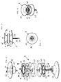
- FIG. 1 - 10 A first embodiment of an anti collision light for an aircraft (hereinafter called ACL) is shown in Figures 1 - 10.
- Figures 1 - 3 show the ACL from the outside in different views wherein it can be seen that the ACL 1 comprises a socket part 4, 5 a main housing 3 and a transparent cover 2. Within the transparent cover 2 the module 8 with the light emitting diodes is placed but is not shown in Figures 1 - 3.
- the exploded view of Figure 4 shows the same elements and exposes the module 8 arranged on the housing part 3 and covered by the transparent cover 2.
- a ring shaped collar 9 mounts the cover 2 to the housing 3 and the module 8 is mounted to the same housing 3 as will be shown later in Figure 8.
- housing 3 the electronic components for feeding the light emitting diodes with power (low voltage dc current) can be arranged on a circuit board 6.
- the housing 3 is closed by a lower part 4 which can belong to the socket or which can be part of the housing 3 itself.
- the socket 4 and 5 can be a screw type socket as shown or any other kind of socket for mounting the ACL to the aircraft as known to the man skilled in the art.
- FIGs 5, 6 and 7 show the module 8 in a preferred special embodiment.
- a plane 12 is shown on which the light emitting diodes are arranged as can be seen in Figure 8.
- a reflecting means 16 in this case a parabolic reflector having a circular upper rim 16' reflects light that is emitted by light emitting diodes upwardly towards the reflecting means 16 in a sidewise manner as indicated by arrows A in Figure 5 since a number of light emitting diodes are arranged, preferably in a circle, around the lower rim 16'' of reflecting means 16.
- a spatial light emitting characteristic of the ACL of 360° can thus be achieved.
- the plane 12 and the reflecting means 16 are preferably arranged on a support 11.
- plane 22 On the same support 11 or on another support there may be another plane 22 which faces with its back the back of plane 12 and which carries a number of light emitting diodes as well.
- a reflecting means 26 is then arranged above plane 22.
- the light emitted by the light emitting diodes on plane 22 is emitted as well away from the plane mostly in a perpendicular direction to the plane and then falls on the reflecting means 26 and is directed sidewardly as is shown for example for a single light beam with arrows B in the same manner as for the other plane 12 with arrows A. So even if the reflecting means 26 is below plane 22 in the drawing it is here in view of the direction of the light said that reflecting means 26 is arranged above plane 22.
- FIG. 8 Exploded view of Figure 8 shows the construction of such an embodiment with two planes 12 and 22 but would be similar if only plane 12 and reflecting means 16 would be present.
- Plane 12 which is the basis for the light emitting diodes 13 is arranged on support 11 but could be of course held in other ways in ACL 1.
- Light emitting diodes 13 are arranged in a circle on plane 12 but of course could be arranged in other closed line forms for example in a rectangular form, open line forms, matrix arrangements or even in a random manner.
- Light emitting diodes 13 are preferably mounted directly on a plane 12 which is a circuit board that comprises the electric connections for the diodes 13.
- the diodes 13 are arranged as already mentioned in such a manner that their main direction of light emission is essentially perpendicular to plane 12.
- Diodes 13 may be arranged and mounted by automatic equipment for arranging electronic parts on printed circuit boards.
- Reflecting means 16 which are shown as the preferred parabolic circular rim reflector already mentioned is fixed to support 11 for example by two screws 66 shown above the reflecting means 16 and which fix as well the module 8 to the housing part 3.
- a printed circuit board 12 is fixed to support 11 by screws as well but could be fixed of course by any known means to the preferred support or by other known means to the housing of the ACL.
- the number of light emitting diodes is 20 but of course the number can be changed.
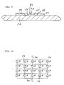
- the light emitting diodes are preferably connected electrically as shown in circuit diagram of Figure 10 and two electric connectors 30 are connecting all light emitting diodes to the electric feeding circuit which has been shown as a printed circuit board 6 in Figure 4 only but which could be of course arranged differently within the ACL.
- Each light emitting diode can be fed with a current of for example 0.5 to 0.8A and with a flash rate of for example 44 pulses per minute.
- the ontime can be for example 250 milliseconds a type of diode suited for such an ACL is for example the type MB042-SOL of red colour.
- FIG. 9 shows an example wherein the light emitting diode chip 13 is mounted directly on printed circuit board plane 12 in known manner and bond wires 13' are connected from chip 13 directly to board 12. It is preferred that a transparent pourable plastic mass 52 for example a silicone mass is used to protect bond wires 13' and the light emitting diode chip 13.
- a frame 15 forms a compartment around each diode and contains the pourable mass 52 until this mass has sufficiently hardened.
- additional light reflecting means are arranged around each or some of the light emitting diodes 13. This can be achieved in an easy manner by having a ring around each or some of diodes 13 with light reflecting tapered sidewalls that reflect light emitted sidewardly by the diodes in a manner essentially perpendicular to plane 12.
- a number of such third reflecting means 15 are shown by holes with tapered walls in a ring shaped plate 14 that is fixed on plane 12 in such a manner that each diode has its own reflector 15.
- Reflector 15 can be at the same time frame 15 of Figure 9 for pouring in said transparent mass 52. In this way most of the light emitted by diodes 13 is emitted perpendicular to plane 12 either directly by the diode or by reflection on reflecting means 15.
- each diode chip can be for example a printed layer on said plane which is covered by a thin gold layer. Only the areas where the bond wires contact circuit board 12 and the printed connectors are leading from the bond wires to the contact areas of electric lines 30 on the printed circuit board are of course not covered by reflector 17.
- another plane 22 can be arranged on support 11 or in another way within the housing of ACL 1 preferably in a back to back position to the first mentioned plane 12.
- this plane 22 and reflecting means 26 are mounted in a similar manner as first plane 12 and reflecting means 16. Screws 66 can be used to fix reflector 26 as well.
- Electric lines 31 are feeding light emitting diodes 23 on plane 22 which diodes are not visible in Figure 8 and are therefore only indicated by arrow 23.
- Additional fourth reflecting means 24 with holes 25 with tapered walls and arranged at the same positions as the light emitting diodes can be present (in the same manner as reflecting means 15) for the light emitting diodes 23 as well.
- the additional reflecting means 17 can be arranged as well on plane 22.
- Figures 11 and 12 show another embodiment similar to the one described before but which does not emit light around a full circle (360°). Accordingly, the support 11 which is preferably used here as well is approximately U-shaped around its rim. The same holds true for circuit boards 50 with their U-shaped rims 32 and 42 and for the arrangement of the light emitting diodes. Third and fourth reflecting means 54 and 64 with holes 55 are preferably present as well.
- the main reflecting means 36 and 46 with their rims 38 and 48 and the U-shaped rims 49 are preferably shaped in a parabolical way as well to direct light emitted by the diodes in a sidewards manner as explained before.
- the module 8 of this kind which is U-shaped or shaped like a horseshoe can be arranged in a bracket 60 as shown in Figures 11 and 12. In this case as well there is a housing which is not shown in the Figures and a clear cover which protects the module.
- the ACL according to the invention is not affected by vibrations as they occur on aircrafts, has low wheigt and a very compact construction.
- the power consumtion is low compared to conventional ACLs.
- the preferred embodiment with feeding circuit and led arrangement within the ACL itself is easy to mount to an airplane and enhances the above advantages.
- the ACL can be NVIS (Night Vision Systems) friendly without special filters due to the spectral characteristics of the LEDs used.
Abstract
Description
- The invention relates to an anti collision light for aircrafts and in particular to such a light with light emitting diodes as light sources.
- The international regulations for airborne aircrafts (e.g. by "EASA" = European Aviation Safety Agency or "FAR" = Federal Aviation Regulations) with fixed wings or rotary wings require an external lighting which in addition to the position lights requires so called anti collision lights which must radiate by day and by night above a certain minimal intensity indicated in Candela. According to EASA the anti collision lights must e.g. radiate in red ("aviation red") or in white ("aviation white") with a predetermined intensity and colour, and also within a given solid angle.
- An usual source for flashing anti collision lights is e.g. provided by Xenon flashing tubes which emit a light spectrum that appears white to the human eye, and which is provided with a red filter (typically red glass) for operation in the red spectral region. It is known as well to provide anti collision lights with light emitting diodes (LEDs) as light sources.
- The present invention aims to provide a LED anti collision light with a compact design and providing ease of manufacturing.
- This goal is met by an anti collision light according to claim 1.
- The common plane allows an automated well defined mounting of the LEDs and an equal reflection angle for all the light beams emitting from the diodes on the reflecting means. These means are preferably common to several or all light emitting diodes.
- In a preferred embodiment a second plane with diodes having their own reflecting means is provided. It is further preferred to provide the planes by circuit boards on which the diodes are mounted and by which the voltage and current is fed directly to the diodes. In another preferred embodiment the diodes are surrounded by third and/or fourth reflecting means and it is preferred in another embodiment to have fifth reflecting means by a reflecting layer on the plane in an area or in areas around some or each of said diodes.
- Further implementations, advantages and applications of the invention can be derived from the dependent claims and from the following description made with the help of the drawings. Therein,
- Figure 1 shows a side view of a first embodiment;
- Figure 2 shows a perspective view of this embodiment;
- Figure 3 shows a top view,
- Figure 4 shows an exploded view of the embodiment;
- Figure 5 shows an inner module of the anti collision light with two planes in a side view;
- Figure 6 shows a perspective view of the module;
- Figure 7 shows a top view of the module,
- Figure 8 shows an exploded view of the module;
- Figure 9 shows a mounted LED;
- Figure 10 shows a circuit diagram of the LEDs;
- Figure 11 shows another embodiment of a module in perspective view; and
- Figure 12 shows the module of Figure 11 in exploded view.
-
- A first embodiment of an anti collision light for an aircraft (hereinafter called ACL) is shown in Figures 1 - 10. Figures 1 - 3 show the ACL from the outside in different views wherein it can be seen that the ACL 1 comprises a socket part 4, 5 a
main housing 3 and atransparent cover 2. Within thetransparent cover 2 themodule 8 with the light emitting diodes is placed but is not shown in Figures 1 - 3. The exploded view of Figure 4 shows the same elements and exposes themodule 8 arranged on thehousing part 3 and covered by thetransparent cover 2. A ring shaped collar 9 mounts thecover 2 to thehousing 3 and themodule 8 is mounted to thesame housing 3 as will be shown later in Figure 8. Withinhousing 3 the electronic components for feeding the light emitting diodes with power (low voltage dc current) can be arranged on a circuit board 6. Thehousing 3 is closed by a lower part 4 which can belong to the socket or which can be part of thehousing 3 itself. Thesocket 4 and 5 can be a screw type socket as shown or any other kind of socket for mounting the ACL to the aircraft as known to the man skilled in the art. - Figures 5, 6 and 7 show the
module 8 in a preferred special embodiment. In the sideview of Figure 5 aplane 12 is shown on which the light emitting diodes are arranged as can be seen in Figure 8. A reflecting means 16 in this case a parabolic reflector having a circular upper rim 16' reflects light that is emitted by light emitting diodes upwardly towards the reflectingmeans 16 in a sidewise manner as indicated by arrows A in Figure 5 since a number of light emitting diodes are arranged, preferably in a circle, around the lower rim 16'' of reflectingmeans 16. A spatial light emitting characteristic of the ACL of 360° can thus be achieved. Theplane 12 and the reflectingmeans 16 are preferably arranged on a support 11. On the same support 11 or on another support there may be anotherplane 22 which faces with its back the back ofplane 12 and which carries a number of light emitting diodes as well. Areflecting means 26 is then arranged aboveplane 22. Above means here that the light emitted by the light emitting diodes onplane 22 is emitted as well away from the plane mostly in a perpendicular direction to the plane and then falls on the reflectingmeans 26 and is directed sidewardly as is shown for example for a single light beam with arrows B in the same manner as for theother plane 12 with arrows A. So even if the reflectingmeans 26 is belowplane 22 in the drawing it is here in view of the direction of the light said that reflectingmeans 26 is arranged aboveplane 22. - Exploded view of Figure 8 shows the construction of such an embodiment with two
planes plane 12 and reflectingmeans 16 would be present.Plane 12 which is the basis for thelight emitting diodes 13 is arranged on support 11 but could be of course held in other ways in ACL 1.Light emitting diodes 13 are arranged in a circle onplane 12 but of course could be arranged in other closed line forms for example in a rectangular form, open line forms, matrix arrangements or even in a random manner.Light emitting diodes 13 are preferably mounted directly on aplane 12 which is a circuit board that comprises the electric connections for thediodes 13. Thediodes 13 are arranged as already mentioned in such a manner that their main direction of light emission is essentially perpendicular to plane 12.Diodes 13 may be arranged and mounted by automatic equipment for arranging electronic parts on printed circuit boards. Reflecting means 16, which are shown as the preferred parabolic circular rim reflector already mentioned is fixed to support 11 for example by twoscrews 66 shown above the reflectingmeans 16 and which fix as well themodule 8 to thehousing part 3. A printedcircuit board 12 is fixed to support 11 by screws as well but could be fixed of course by any known means to the preferred support or by other known means to the housing of the ACL. - In this preferred embodiment the number of light emitting diodes is 20 but of course the number can be changed. The light emitting diodes are preferably connected electrically as shown in circuit diagram of Figure 10 and two
electric connectors 30 are connecting all light emitting diodes to the electric feeding circuit which has been shown as a printed circuit board 6 in Figure 4 only but which could be of course arranged differently within the ACL. Each light emitting diode can be fed with a current of for example 0.5 to 0.8A and with a flash rate of for example 44 pulses per minute. The ontime can be for example 250 milliseconds a type of diode suited for such an ACL is for example the type MB042-SOL of red colour. As already mentioned it is preferred to arrange the light emitting diodes directly on theplane 12 which is a circuit board. Figure 9 shows an example wherein the lightemitting diode chip 13 is mounted directly on printedcircuit board plane 12 in known manner and bond wires 13' are connected fromchip 13 directly toboard 12. It is preferred that a transparent pourableplastic mass 52 for example a silicone mass is used to protect bond wires 13' and the lightemitting diode chip 13. Aframe 15 forms a compartment around each diode and contains thepourable mass 52 until this mass has sufficiently hardened. - In a preferred embodiment as shown, additional light reflecting means are arranged around each or some of the
light emitting diodes 13. This can be achieved in an easy manner by having a ring around each or some ofdiodes 13 with light reflecting tapered sidewalls that reflect light emitted sidewardly by the diodes in a manner essentially perpendicular to plane 12. In Figure 8 a number of such third reflectingmeans 15 are shown by holes with tapered walls in a ring shapedplate 14 that is fixed onplane 12 in such a manner that each diode has itsown reflector 15.Reflector 15 can be at thesame time frame 15 of Figure 9 for pouring in saidtransparent mass 52. In this way most of the light emitted bydiodes 13 is emitted perpendicular to plane 12 either directly by the diode or by reflection on reflectingmeans 15. - As another additional reflecting means 17 it is preferred to have a reflecting surface layer on
plane 12 around each diode chip which can be for example a printed layer on said plane which is covered by a thin gold layer. Only the areas where the bond wirescontact circuit board 12 and the printed connectors are leading from the bond wires to the contact areas ofelectric lines 30 on the printed circuit board are of course not covered byreflector 17. - As shown here as a preferred embodiment only another
plane 22 can be arranged on support 11 or in another way within the housing of ACL 1 preferably in a back to back position to the first mentionedplane 12. As can easily be seen in Figure 8 thisplane 22 and reflectingmeans 26 are mounted in a similar manner asfirst plane 12 and reflectingmeans 16.Screws 66 can be used to fixreflector 26 as well.Electric lines 31 are feeding light emittingdiodes 23 onplane 22 which diodes are not visible in Figure 8 and are therefore only indicated byarrow 23. Additional fourth reflecting means 24 withholes 25 with tapered walls and arranged at the same positions as the light emitting diodes can be present (in the same manner as reflecting means 15) for thelight emitting diodes 23 as well. For those diodes the additional reflecting means 17 can be arranged as well onplane 22. - Figures 11 and 12 show another embodiment similar to the one described before but which does not emit light around a full circle (360°). Accordingly, the support 11 which is preferably used here as well is approximately U-shaped around its rim. The same holds true for circuit boards 50 with their
U-shaped rims U-shaped rims 49 are preferably shaped in a parabolical way as well to direct light emitted by the diodes in a sidewards manner as explained before. Themodule 8 of this kind which is U-shaped or shaped like a horseshoe can be arranged in abracket 60 as shown in Figures 11 and 12. In this case as well there is a housing which is not shown in the Figures and a clear cover which protects the module. - The ACL according to the invention is not affected by vibrations as they occur on aircrafts, has low wheigt and a very compact construction. The power consumtion is low compared to conventional ACLs. The preferred embodiment with feeding circuit and led arrangement within the ACL itself is easy to mount to an airplane and enhances the above advantages. The ACL can be NVIS (Night Vision Systems) friendly without special filters due to the spectral characteristics of the LEDs used.
Claims (19)
- Anti collision light (1) for aircrafts comprising a number of light emitting diodes (13) arranged on a common plane (12) and reflecting means (16) arranged above the plane for reflecting light emitting from the diodes essentially perpendicular to said plane in a sidewards direction, and in particular wherein the reflecting means (16) is a reflector common to several or all diodes.
- Anti collision light according to claim 1 comprising a second plane (22) common to a second number of light emitting diodes (23) arranged thereon, the first and second planes (12, 22) being arranged essentially coplanar in a back to back facing manner, and a second reflecting means (26) arranged above the second plane for reflecting light emitting from the diodes of the second number of diodes essentially perpendicular to the second plane in a sidewards direction, and in particular wherein the second reflecting means (26) is a reflector common to several or all diodes of said second number of diodes.
- Anti collision light according to claim 1 or 2 wherein the plane (12) or both planes (12, 22) if the case may be, are circuit boards on which light emitting diode chips are directly mounted.
- Anti collision light according to one of claims 1 to 3 wherein some or each light emitting diodes (13, 23), or groups of several diodes together, are surrounded by third reflecting means (15) belonging to the first number of diodes (13) and/or fourth reflecting means (25) belonging to said second number of diodes (23), directing light emitted sidewardly by the diode or the diodes in a direction essentially perpendicular to said plane (12) or said planes (12, 22) respectively.
- Anti collision light according to claim 4 wherein said third or fourth reflecting means (15, 25) are mounted on the plane or the planes, respectively.
- Anti collision light according to claim 4 or 5, respectively, wherein said third or fourth reflecting means (15, 25) are ring shaped parts having holes with tapered, reflecting sidewalls, the holes being arranged correspondingly with the positions of said light emitting diodes on said plane or said planes, respectively.
- Anti collision light according to one of claims 1 to 6 wherein the light emitting diodes are arranged along a closed line on the plane or planes, respectively, in particular in a circle, or are arranged along an open line on said plane or said planes, respectively, in particular in a horseshoe-like shape, or are arranged in a matrix-like shape.
- Anti collision light according to one of claims 1 to 7 wherein additional reflecting means (17) are provided by a reflecting layer on the plane (12) or the planes (12, 22), respectively, for some or for each of said diodes, respectively.
- Anti collision light according to one of claims 1 to 8 wherein said reflecting means (16, 26) above said plane (12) or said planes (12, 22) are parabolically shaped and are provided with a circular outer rim (16').
- Anti collision light according to claim 9 wherein said plane (12) or said planes (12, 22) are circular plates or circuit boards, respectively.
- Anti collision light according to claims 1 to 8 wherein said reflecting means (36, 46) above said plane (32) or said planes (32, 42) are parabolically shaped and are provided with two separate rims (38, 48) extending from said plane (32) or said planes (32, 42), respectively, and with an outer rim (49) which is U-shaped.
- Anti collision light according to claim 11 wherein said plane (32) or said planes (32, 42) are plates or circuit boards, respectively with a U-shaped rim (50) extending form a linear base (51).
- Anti collision light according to one of claims 1 to 12 wherein the light emitting diodes are lensless.
- Anti collision light according to one of claims 1 to 13 wherein the light emitting diodes (13) are covered by a light transparent mass (52), in particular by a pourable silicone mass.
- Anti collision light according to claim 14 wherein said reflecting means (15, 25) arranged around said diodes, and in particular said third or fourth reflecting means, respectively, form a frame for said mass.
- Anti collision light according to claim 2 wherein a support (11) is provided for said back to back facing planes, which are spaced apart by said support.
- Anti collision light according to one of claims 2 to 16 wherein said planes and said reflecting means above said planes are arranged along a common longitudinal axis and in particular in the same axis as socket (4, 5) of the anti collision light.
- Anti collision light according to one of claims 2 to 17 wherein said planes and said reflecting means above said planes are arranged along a common axis and placed within a U-shaped bracket(60).
- Anti collision light according to one of claims 1 to 18 wherein the light emitting diodes and a circuit board (6) for the electrical feeding circuit for the diodes are arranged within the housing of the anti collision light (2,3) and in particular the circuit board is arranged coplanar to the plane (12) or planes (12,22), respectively.
Priority Applications (4)
| Application Number | Priority Date | Filing Date | Title |
|---|---|---|---|
| EP04024156A EP1510457B1 (en) | 2004-10-11 | 2004-10-11 | Anti collision light for aircraft |
| AT04024156T ATE385952T1 (en) | 2004-10-11 | 2004-10-11 | ANTI-COLLISION LIGHT FOR AIRCRAFT |
| DE602004011708T DE602004011708T2 (en) | 2004-10-11 | 2004-10-11 | Anti-collision light for aircraft |
| US11/033,275 US7236105B2 (en) | 2004-10-11 | 2005-01-12 | Anti collision light for aircraft |
Applications Claiming Priority (1)
| Application Number | Priority Date | Filing Date | Title |
|---|---|---|---|
| EP04024156A EP1510457B1 (en) | 2004-10-11 | 2004-10-11 | Anti collision light for aircraft |
Publications (3)
| Publication Number | Publication Date |
|---|---|
| EP1510457A2 true EP1510457A2 (en) | 2005-03-02 |
| EP1510457A3 EP1510457A3 (en) | 2005-04-06 |
| EP1510457B1 EP1510457B1 (en) | 2008-02-13 |
Family
ID=34089806
Family Applications (1)
| Application Number | Title | Priority Date | Filing Date |
|---|---|---|---|
| EP04024156A Not-in-force EP1510457B1 (en) | 2004-10-11 | 2004-10-11 | Anti collision light for aircraft |
Country Status (4)
| Country | Link |
|---|---|
| US (1) | US7236105B2 (en) |
| EP (1) | EP1510457B1 (en) |
| AT (1) | ATE385952T1 (en) |
| DE (1) | DE602004011708T2 (en) |
Cited By (9)
| Publication number | Priority date | Publication date | Assignee | Title |
|---|---|---|---|---|
| WO2006091225A1 (en) * | 2005-01-13 | 2006-08-31 | Honeywell International, Inc. | Body mounted led-based anti-collision light for aircraft |
| FR2886713A1 (en) * | 2005-06-06 | 2006-12-08 | Ece Soc Par Actions Simplifiee | Anti-collision light for e.g. airplane, has reflecting units, with transversal section, comprising reflecting surfaces with conic portion and having optical axes oriented perpendicular with respect to direction to be lit |
| EP2003058A1 (en) * | 2007-06-13 | 2008-12-17 | Flight Components AG | Anti-collision light for an aircraft |
| EP2157017A3 (en) * | 2008-08-19 | 2012-07-25 | Honeywell International Inc. | Systems and methods for aircraft LED anti collision light |
| WO2013107731A1 (en) * | 2012-01-18 | 2013-07-25 | Osram Gmbh | Illuminating device and luminaire having the illuminating device |
| EP2730462A1 (en) * | 2012-11-07 | 2014-05-14 | Hella KGaA Hueck & Co | LED Lamp |
| ITUD20130113A1 (en) * | 2013-09-02 | 2015-03-03 | Calzavara Spa | LUMINOUS SIGNALING DEVICE |
| CN104879709A (en) * | 2015-05-05 | 2015-09-02 | 兰州万里航空机电有限责任公司 | LED long-life aircraft anti-collision light |
| EP2694861B1 (en) * | 2011-04-08 | 2017-01-04 | Dialight Corporation | High intensity warning light with reflector and light-emitting diodes |
Families Citing this family (20)
| Publication number | Priority date | Publication date | Assignee | Title |
|---|---|---|---|---|
| BRPI0513146A (en) * | 2004-07-06 | 2008-04-29 | Honeywell Int Inc | anti-collision lighting device |
| US20090010013A1 (en) * | 2007-07-02 | 2009-01-08 | Andre Hessling | Light for a vehicle, particularly flash warning light for an aircraft |
| US8665138B2 (en) * | 2007-07-17 | 2014-03-04 | Laufer Wind Group Llc | Method and system for reducing light pollution |
| US8454212B2 (en) * | 2007-12-28 | 2013-06-04 | Sirio Panel S.P.A. | Anti-collision light for aircraft |
| US20100027292A1 (en) * | 2008-07-29 | 2010-02-04 | Yun-Yuan Yeh | Light guiding structure |
| US20100027281A1 (en) * | 2008-07-31 | 2010-02-04 | Waters Stanley E | LED Anti-Collision Light for Commercial Aircraft |
| US20100090866A1 (en) * | 2008-10-13 | 2010-04-15 | Howard Chen | Optical Distress Beacon For Use In Space Environments |
| US7963683B2 (en) * | 2008-12-22 | 2011-06-21 | Federal Signal Corporation | Rotating light |
| US8192060B2 (en) * | 2009-07-23 | 2012-06-05 | Dean Andrew Wilkinson | Aircraft navigation light |
| US8662721B2 (en) * | 2009-11-26 | 2014-03-04 | Nathan Howard Calvin | Aircraft external lighting system and method |
| US9016896B1 (en) | 2011-02-23 | 2015-04-28 | Hughey & Phillips, Llc | Obstruction lighting system |
| US9013331B2 (en) | 2011-03-17 | 2015-04-21 | Hughey & Phillips, Llc | Lighting and collision alerting system |
| EP3299704A1 (en) | 2011-03-17 | 2018-03-28 | Hughey & Phillips, LLC | Lighting system |
| EP2663162B1 (en) * | 2012-05-10 | 2017-01-11 | Goodrich Lighting Systems GmbH | LED flash light and method for indicating near-end-of-life status of such an LED flash light |
| CA2927419A1 (en) | 2015-04-16 | 2016-10-16 | Hughey & Phillips, Llc | Obstruction lighting system configured to emit visible and infrared light |
| US10004126B2 (en) * | 2015-06-22 | 2018-06-19 | Goodrich Lighting Systems, Inc. | Lighting-system color-shift detection and correction |
| US11178741B1 (en) | 2015-12-22 | 2021-11-16 | Hughey & Phillips, Llc | Lighting system configured to emit visible and infrared light |
| EP3670356B1 (en) | 2018-12-17 | 2023-08-30 | Goodrich Lighting Systems GmbH | Combined forward navigation and anti-collision light for an aircraft and aircraft comprising the same |
| US11046455B2 (en) * | 2019-10-23 | 2021-06-29 | B/E Aerospace, Inc. | Anti-collision light assembly |
| EP4124794A1 (en) | 2021-07-28 | 2023-02-01 | Goodrich Lighting Systems GmbH & Co. KG | Exterior aircraft light and aircraft comprising the same |
Citations (8)
| Publication number | Priority date | Publication date | Assignee | Title |
|---|---|---|---|---|
| US4935665A (en) * | 1987-12-24 | 1990-06-19 | Mitsubishi Cable Industries Ltd. | Light emitting diode lamp |
| JP2000045237A (en) * | 1998-07-31 | 2000-02-15 | Toshiba Lighting & Technology Corp | Marker lamp |
| US6367949B1 (en) * | 1999-08-04 | 2002-04-09 | 911 Emergency Products, Inc. | Par 36 LED utility lamp |
| US20020101189A1 (en) * | 2000-12-20 | 2002-08-01 | Vo Nam H. | Led strobe light |
| DE20311169U1 (en) * | 2003-07-21 | 2003-10-09 | Hella Kg Hueck & Co | Signal lamp with LED panel, light emitting diode (LED) set, whose light is reflected by fixed reflector to LED panel |
| US20030193807A1 (en) * | 2002-04-16 | 2003-10-16 | Alexander Rizkin | LED-based elevated omnidirectional airfield light |
| US20040075575A1 (en) * | 1998-11-06 | 2004-04-22 | Demarco Ralph Anthony | Recognition/anti-collision light for aircraft |
| US20040085779A1 (en) * | 2002-10-01 | 2004-05-06 | Pond Gregory R. | Light emitting diode headlamp and headlamp assembly |
Family Cites Families (18)
| Publication number | Priority date | Publication date | Assignee | Title |
|---|---|---|---|---|
| US2555807A (en) * | 1946-08-08 | 1951-06-05 | Gyrodyne Company Of America In | Wing tip light for rotary wing aircraft |
| US3174552A (en) * | 1963-12-09 | 1965-03-23 | Charles Adair | Rotary wing aircraft |
| JPS5565911A (en) * | 1978-11-10 | 1980-05-17 | Canon Inc | Optical system of copying machine |
| US4527158A (en) * | 1982-07-29 | 1985-07-02 | Runnels Russell W | Aircraft collision pilot warning indicating system |
| EP0208859B1 (en) * | 1985-07-04 | 1990-03-21 | BBC Brown Boveri AG | Three-phase excitation for synchronons machines |
| US4829407A (en) * | 1987-11-06 | 1989-05-09 | Oxley Developments Company Limited | Indicator lamps |
| FR2690710B1 (en) * | 1992-04-30 | 1994-06-17 | Snecma | DEVICE FOR DETECTING A FAILURE IN AN OIL / FUEL EXCHANGER. |
| JPH07201210A (en) * | 1993-12-29 | 1995-08-04 | Patoraito:Kk | Light source structure of signal display lamp |
| US5499010A (en) | 1994-04-25 | 1996-03-12 | The Regents Of The University Of California | Braking light system for a vehicle |
| US5710560A (en) * | 1994-04-25 | 1998-01-20 | The Regents Of The University Of California | Method and apparatus for enhancing visual perception of display lights, warning lights and the like, and of stimuli used in testing for ocular disease |
| US5579162A (en) * | 1994-10-31 | 1996-11-26 | Viratec Thin Films, Inc. | Antireflection coating for a temperature sensitive substrate |
| GB9603350D0 (en) * | 1995-04-05 | 1996-04-17 | Oxley Dev Co Ltd | Aircraft lighting system |
| US5929788A (en) * | 1997-12-30 | 1999-07-27 | Star Headlight & Lantern Co. | Warning beacon |
| US6464373B1 (en) * | 2000-11-03 | 2002-10-15 | Twr Lighting, Inc. | Light emitting diode lighting with frustoconical reflector |
| EP1270409A1 (en) | 2001-06-15 | 2003-01-02 | Flight Components AG | Anti collision light with infra red filter for aircraft |
| DE20114306U1 (en) * | 2001-08-31 | 2002-01-10 | Aqua Signal Ag | Lighting system especially as a hazard fire, obstacle fire or day and night markings |
| US6525668B1 (en) * | 2001-10-10 | 2003-02-25 | Twr Lighting, Inc. | LED array warning light system |
| US7079041B2 (en) * | 2003-11-21 | 2006-07-18 | Whelen Engineering Company, Inc. | LED aircraft anticollision beacon |
-
2004
- 2004-10-11 EP EP04024156A patent/EP1510457B1/en not_active Not-in-force
- 2004-10-11 AT AT04024156T patent/ATE385952T1/en not_active IP Right Cessation
- 2004-10-11 DE DE602004011708T patent/DE602004011708T2/en active Active
-
2005
- 2005-01-12 US US11/033,275 patent/US7236105B2/en not_active Expired - Fee Related
Patent Citations (8)
| Publication number | Priority date | Publication date | Assignee | Title |
|---|---|---|---|---|
| US4935665A (en) * | 1987-12-24 | 1990-06-19 | Mitsubishi Cable Industries Ltd. | Light emitting diode lamp |
| JP2000045237A (en) * | 1998-07-31 | 2000-02-15 | Toshiba Lighting & Technology Corp | Marker lamp |
| US20040075575A1 (en) * | 1998-11-06 | 2004-04-22 | Demarco Ralph Anthony | Recognition/anti-collision light for aircraft |
| US6367949B1 (en) * | 1999-08-04 | 2002-04-09 | 911 Emergency Products, Inc. | Par 36 LED utility lamp |
| US20020101189A1 (en) * | 2000-12-20 | 2002-08-01 | Vo Nam H. | Led strobe light |
| US20030193807A1 (en) * | 2002-04-16 | 2003-10-16 | Alexander Rizkin | LED-based elevated omnidirectional airfield light |
| US20040085779A1 (en) * | 2002-10-01 | 2004-05-06 | Pond Gregory R. | Light emitting diode headlamp and headlamp assembly |
| DE20311169U1 (en) * | 2003-07-21 | 2003-10-09 | Hella Kg Hueck & Co | Signal lamp with LED panel, light emitting diode (LED) set, whose light is reflected by fixed reflector to LED panel |
Non-Patent Citations (1)
| Title |
|---|
| PATENT ABSTRACTS OF JAPAN vol. 2000, no. 05, 14 September 2000 (2000-09-14) & JP 2000 045237 A (TOSHIBA LIGHTING &TECHNOLOGY CORP), 15 February 2000 (2000-02-15) * |
Cited By (12)
| Publication number | Priority date | Publication date | Assignee | Title |
|---|---|---|---|---|
| WO2006091225A1 (en) * | 2005-01-13 | 2006-08-31 | Honeywell International, Inc. | Body mounted led-based anti-collision light for aircraft |
| US7645053B2 (en) | 2005-01-13 | 2010-01-12 | Honeywell International Inc. | Rotationally symmetrical LED-based anti-collision light for aircraft |
| FR2886713A1 (en) * | 2005-06-06 | 2006-12-08 | Ece Soc Par Actions Simplifiee | Anti-collision light for e.g. airplane, has reflecting units, with transversal section, comprising reflecting surfaces with conic portion and having optical axes oriented perpendicular with respect to direction to be lit |
| EP1731423A1 (en) * | 2005-06-06 | 2006-12-13 | Ece | Anti-collision light |
| EP2003058A1 (en) * | 2007-06-13 | 2008-12-17 | Flight Components AG | Anti-collision light for an aircraft |
| US7794110B2 (en) | 2007-06-13 | 2010-09-14 | Flight Components Ag | Anti-collision light for an aircraft |
| EP2157017A3 (en) * | 2008-08-19 | 2012-07-25 | Honeywell International Inc. | Systems and methods for aircraft LED anti collision light |
| EP2694861B1 (en) * | 2011-04-08 | 2017-01-04 | Dialight Corporation | High intensity warning light with reflector and light-emitting diodes |
| WO2013107731A1 (en) * | 2012-01-18 | 2013-07-25 | Osram Gmbh | Illuminating device and luminaire having the illuminating device |
| EP2730462A1 (en) * | 2012-11-07 | 2014-05-14 | Hella KGaA Hueck & Co | LED Lamp |
| ITUD20130113A1 (en) * | 2013-09-02 | 2015-03-03 | Calzavara Spa | LUMINOUS SIGNALING DEVICE |
| CN104879709A (en) * | 2015-05-05 | 2015-09-02 | 兰州万里航空机电有限责任公司 | LED long-life aircraft anti-collision light |
Also Published As
| Publication number | Publication date |
|---|---|
| DE602004011708D1 (en) | 2008-03-27 |
| EP1510457A3 (en) | 2005-04-06 |
| US7236105B2 (en) | 2007-06-26 |
| DE602004011708T2 (en) | 2009-01-29 |
| EP1510457B1 (en) | 2008-02-13 |
| ATE385952T1 (en) | 2008-03-15 |
| US20060077071A1 (en) | 2006-04-13 |
Similar Documents
| Publication | Publication Date | Title |
|---|---|---|
| EP1510457B1 (en) | Anti collision light for aircraft | |
| EP2003058B1 (en) | Anti-collision light for an aircraft | |
| US7434970B2 (en) | Multi-platform LED-based aircraft rear position light | |
| JP5779329B2 (en) | Vehicle lighting | |
| US6431728B1 (en) | Multi-array LED warning lights | |
| US7431486B2 (en) | LED assembly for rear lamps in an automobile | |
| US6568833B2 (en) | Light | |
| US7168827B2 (en) | Side emitter beacon | |
| EP2157017A2 (en) | Systems and methods for aircraft LED anti collision light | |
| JP2007513488A (en) | Multi-platform aircraft forward aviation position light using LED-based light source | |
| EP2355620A1 (en) | A driving circuit of semiconductor-type light source for vehicle lighting device and a vehicle lighting device | |
| JP2011171277A (en) | Light source unit for semiconductor type light source of vehicle lighting device, and vehicle lighting device | |
| EP2407712A2 (en) | Light source unit of semiconductor-type light source of vehicle lighting device and vehicle lighting device | |
| US10054283B2 (en) | Compact multi-function LED lighthead | |
| JP2012074186A (en) | Light source unit of semiconductor type light source of lamp fixture for vehicle and lamp fixture for vehicle | |
| US7040786B2 (en) | Anticollision light for aircraft | |
| US20140085918A1 (en) | Device for interior lighting in a motor vehicle | |
| EP3800396B1 (en) | Vehicle light fixture | |
| JP5407026B2 (en) | Light source unit of semiconductor light source for vehicle lamp, vehicle lamp | |
| US10655807B2 (en) | Method and apparatus for vehicle lighting | |
| US20240044472A1 (en) | Light source for the signalling system of a motor vehicle | |
| JP2004343025A (en) | Led electric bulb | |
| JP2000294007A (en) | Lighting system and warning light on runway |
Legal Events
| Date | Code | Title | Description |
|---|---|---|---|
| PUAI | Public reference made under article 153(3) epc to a published international application that has entered the european phase |
Free format text: ORIGINAL CODE: 0009012 |
|
| PUAL | Search report despatched |
Free format text: ORIGINAL CODE: 0009013 |
|
| AK | Designated contracting states |
Kind code of ref document: A2 Designated state(s): AT BE BG CH CY CZ DE DK EE ES FI FR GB GR HU IE IT LI LU MC NL PL PT RO SE SI SK TR |
|
| AX | Request for extension of the european patent |
Extension state: AL HR LT LV MK |
|
| AK | Designated contracting states |
Kind code of ref document: A3 Designated state(s): AT BE BG CH CY CZ DE DK EE ES FI FR GB GR HU IE IT LI LU MC NL PL PT RO SE SI SK TR |
|
| AX | Request for extension of the european patent |
Extension state: AL HR LT LV MK |
|
| 17P | Request for examination filed |
Effective date: 20051004 |
|
| AKX | Designation fees paid |
Designated state(s): AT BE BG CH CY CZ DE DK EE ES FI FR GB GR HU IE IT LI LU MC NL PL PT RO SE SI SK TR |
|
| 17Q | First examination report despatched |
Effective date: 20051125 |
|
| GRAP | Despatch of communication of intention to grant a patent |
Free format text: ORIGINAL CODE: EPIDOSNIGR1 |
|
| GRAS | Grant fee paid |
Free format text: ORIGINAL CODE: EPIDOSNIGR3 |
|
| GRAA | (expected) grant |
Free format text: ORIGINAL CODE: 0009210 |
|
| AK | Designated contracting states |
Kind code of ref document: B1 Designated state(s): AT BE BG CH CY CZ DE DK EE ES FI FR GB GR HU IE IT LI LU MC NL PL PT RO SE SI SK TR |
|
| REG | Reference to a national code |
Ref country code: GB Ref legal event code: FG4D |
|
| REG | Reference to a national code |
Ref country code: CH Ref legal event code: NV Representative=s name: E. BLUM & CO. AG PATENT- UND MARKENANWAELTE VSP Ref country code: CH Ref legal event code: EP |
|
| REG | Reference to a national code |
Ref country code: IE Ref legal event code: FG4D |
|
| REF | Corresponds to: |
Ref document number: 602004011708 Country of ref document: DE Date of ref document: 20080327 Kind code of ref document: P |
|
| PG25 | Lapsed in a contracting state [announced via postgrant information from national office to epo] |
Ref country code: FI Free format text: LAPSE BECAUSE OF FAILURE TO SUBMIT A TRANSLATION OF THE DESCRIPTION OR TO PAY THE FEE WITHIN THE PRESCRIBED TIME-LIMIT Effective date: 20080213 Ref country code: ES Free format text: LAPSE BECAUSE OF FAILURE TO SUBMIT A TRANSLATION OF THE DESCRIPTION OR TO PAY THE FEE WITHIN THE PRESCRIBED TIME-LIMIT Effective date: 20080524 |
|
| NLV1 | Nl: lapsed or annulled due to failure to fulfill the requirements of art. 29p and 29m of the patents act | ||
| PG25 | Lapsed in a contracting state [announced via postgrant information from national office to epo] |
Ref country code: AT Free format text: LAPSE BECAUSE OF FAILURE TO SUBMIT A TRANSLATION OF THE DESCRIPTION OR TO PAY THE FEE WITHIN THE PRESCRIBED TIME-LIMIT Effective date: 20080213 |
|
| ET | Fr: translation filed | ||
| PG25 | Lapsed in a contracting state [announced via postgrant information from national office to epo] |
Ref country code: BE Free format text: LAPSE BECAUSE OF FAILURE TO SUBMIT A TRANSLATION OF THE DESCRIPTION OR TO PAY THE FEE WITHIN THE PRESCRIBED TIME-LIMIT Effective date: 20080213 Ref country code: PL Free format text: LAPSE BECAUSE OF FAILURE TO SUBMIT A TRANSLATION OF THE DESCRIPTION OR TO PAY THE FEE WITHIN THE PRESCRIBED TIME-LIMIT Effective date: 20080213 Ref country code: SI Free format text: LAPSE BECAUSE OF FAILURE TO SUBMIT A TRANSLATION OF THE DESCRIPTION OR TO PAY THE FEE WITHIN THE PRESCRIBED TIME-LIMIT Effective date: 20080213 |
|
| PG25 | Lapsed in a contracting state [announced via postgrant information from national office to epo] |
Ref country code: DK Free format text: LAPSE BECAUSE OF FAILURE TO SUBMIT A TRANSLATION OF THE DESCRIPTION OR TO PAY THE FEE WITHIN THE PRESCRIBED TIME-LIMIT Effective date: 20080213 Ref country code: NL Free format text: LAPSE BECAUSE OF FAILURE TO SUBMIT A TRANSLATION OF THE DESCRIPTION OR TO PAY THE FEE WITHIN THE PRESCRIBED TIME-LIMIT Effective date: 20080213 Ref country code: PT Free format text: LAPSE BECAUSE OF FAILURE TO SUBMIT A TRANSLATION OF THE DESCRIPTION OR TO PAY THE FEE WITHIN THE PRESCRIBED TIME-LIMIT Effective date: 20080714 Ref country code: SE Free format text: LAPSE BECAUSE OF FAILURE TO SUBMIT A TRANSLATION OF THE DESCRIPTION OR TO PAY THE FEE WITHIN THE PRESCRIBED TIME-LIMIT Effective date: 20080513 Ref country code: CZ Free format text: LAPSE BECAUSE OF FAILURE TO SUBMIT A TRANSLATION OF THE DESCRIPTION OR TO PAY THE FEE WITHIN THE PRESCRIBED TIME-LIMIT Effective date: 20080213 Ref country code: SK Free format text: LAPSE BECAUSE OF FAILURE TO SUBMIT A TRANSLATION OF THE DESCRIPTION OR TO PAY THE FEE WITHIN THE PRESCRIBED TIME-LIMIT Effective date: 20080213 |
|
| PG25 | Lapsed in a contracting state [announced via postgrant information from national office to epo] |
Ref country code: RO Free format text: LAPSE BECAUSE OF FAILURE TO SUBMIT A TRANSLATION OF THE DESCRIPTION OR TO PAY THE FEE WITHIN THE PRESCRIBED TIME-LIMIT Effective date: 20080213 |
|
| PLBE | No opposition filed within time limit |
Free format text: ORIGINAL CODE: 0009261 |
|
| STAA | Information on the status of an ep patent application or granted ep patent |
Free format text: STATUS: NO OPPOSITION FILED WITHIN TIME LIMIT |
|
| 26N | No opposition filed |
Effective date: 20081114 |
|
| PG25 | Lapsed in a contracting state [announced via postgrant information from national office to epo] |
Ref country code: BG Free format text: LAPSE BECAUSE OF FAILURE TO SUBMIT A TRANSLATION OF THE DESCRIPTION OR TO PAY THE FEE WITHIN THE PRESCRIBED TIME-LIMIT Effective date: 20080513 Ref country code: EE Free format text: LAPSE BECAUSE OF FAILURE TO SUBMIT A TRANSLATION OF THE DESCRIPTION OR TO PAY THE FEE WITHIN THE PRESCRIBED TIME-LIMIT Effective date: 20080213 |
|
| PG25 | Lapsed in a contracting state [announced via postgrant information from national office to epo] |
Ref country code: MC Free format text: LAPSE BECAUSE OF NON-PAYMENT OF DUE FEES Effective date: 20081031 |
|
| PG25 | Lapsed in a contracting state [announced via postgrant information from national office to epo] |
Ref country code: CY Free format text: LAPSE BECAUSE OF FAILURE TO SUBMIT A TRANSLATION OF THE DESCRIPTION OR TO PAY THE FEE WITHIN THE PRESCRIBED TIME-LIMIT Effective date: 20080213 |
|
| PG25 | Lapsed in a contracting state [announced via postgrant information from national office to epo] |
Ref country code: IE Free format text: LAPSE BECAUSE OF NON-PAYMENT OF DUE FEES Effective date: 20081013 |
|
| PG25 | Lapsed in a contracting state [announced via postgrant information from national office to epo] |
Ref country code: HU Free format text: LAPSE BECAUSE OF FAILURE TO SUBMIT A TRANSLATION OF THE DESCRIPTION OR TO PAY THE FEE WITHIN THE PRESCRIBED TIME-LIMIT Effective date: 20080814 Ref country code: LU Free format text: LAPSE BECAUSE OF NON-PAYMENT OF DUE FEES Effective date: 20081011 |
|
| PG25 | Lapsed in a contracting state [announced via postgrant information from national office to epo] |
Ref country code: TR Free format text: LAPSE BECAUSE OF FAILURE TO SUBMIT A TRANSLATION OF THE DESCRIPTION OR TO PAY THE FEE WITHIN THE PRESCRIBED TIME-LIMIT Effective date: 20080213 |
|
| REG | Reference to a national code |
Ref country code: CH Ref legal event code: PFA Owner name: EMTEQ EUROPE GMBH Free format text: FLIGHT COMPONENTS AG#BITZIBERGSTRASSE 5#8184 BACHENBUELACH (CH) -TRANSFER TO- EMTEQ EUROPE GMBH#BITZIBERGSTRASSE 5#8184 BACHENBUELACH (CH) |
|
| PG25 | Lapsed in a contracting state [announced via postgrant information from national office to epo] |
Ref country code: GR Free format text: LAPSE BECAUSE OF FAILURE TO SUBMIT A TRANSLATION OF THE DESCRIPTION OR TO PAY THE FEE WITHIN THE PRESCRIBED TIME-LIMIT Effective date: 20080514 |
|
| REG | Reference to a national code |
Ref country code: FR Ref legal event code: CD |
|
| PGFP | Annual fee paid to national office [announced via postgrant information from national office to epo] |
Ref country code: CH Payment date: 20130906 Year of fee payment: 10 |
|
| PGFP | Annual fee paid to national office [announced via postgrant information from national office to epo] |
Ref country code: FR Payment date: 20131022 Year of fee payment: 10 Ref country code: DE Payment date: 20131021 Year of fee payment: 10 Ref country code: GB Payment date: 20131021 Year of fee payment: 10 |
|
| PGFP | Annual fee paid to national office [announced via postgrant information from national office to epo] |
Ref country code: IT Payment date: 20131024 Year of fee payment: 10 |
|
| REG | Reference to a national code |
Ref country code: DE Ref legal event code: R119 Ref document number: 602004011708 Country of ref document: DE |
|
| REG | Reference to a national code |
Ref country code: CH Ref legal event code: PL |
|
| GBPC | Gb: european patent ceased through non-payment of renewal fee |
Effective date: 20141011 |
|
| PG25 | Lapsed in a contracting state [announced via postgrant information from national office to epo] |
Ref country code: GB Free format text: LAPSE BECAUSE OF NON-PAYMENT OF DUE FEES Effective date: 20141011 Ref country code: LI Free format text: LAPSE BECAUSE OF NON-PAYMENT OF DUE FEES Effective date: 20141031 Ref country code: CH Free format text: LAPSE BECAUSE OF NON-PAYMENT OF DUE FEES Effective date: 20141031 Ref country code: DE Free format text: LAPSE BECAUSE OF NON-PAYMENT OF DUE FEES Effective date: 20150501 |
|
| REG | Reference to a national code |
Ref country code: FR Ref legal event code: ST Effective date: 20150630 |
|
| PG25 | Lapsed in a contracting state [announced via postgrant information from national office to epo] |
Ref country code: FR Free format text: LAPSE BECAUSE OF NON-PAYMENT OF DUE FEES Effective date: 20141031 Ref country code: IT Free format text: LAPSE BECAUSE OF NON-PAYMENT OF DUE FEES Effective date: 20141011 |