EP1510267B1 - Method for displaying die layout in press brake and apparatus therefor - Google Patents
Method for displaying die layout in press brake and apparatus therefor Download PDFInfo
- Publication number
- EP1510267B1 EP1510267B1 EP04025205A EP04025205A EP1510267B1 EP 1510267 B1 EP1510267 B1 EP 1510267B1 EP 04025205 A EP04025205 A EP 04025205A EP 04025205 A EP04025205 A EP 04025205A EP 1510267 B1 EP1510267 B1 EP 1510267B1
- Authority
- EP
- European Patent Office
- Prior art keywords
- dies
- displayed
- product
- bending
- displaying
- Prior art date
- Legal status (The legal status is an assumption and is not a legal conclusion. Google has not performed a legal analysis and makes no representation as to the accuracy of the status listed.)
- Expired - Lifetime
Links
Images


Classifications
-
- G—PHYSICS
- G05—CONTROLLING; REGULATING
- G05B—CONTROL OR REGULATING SYSTEMS IN GENERAL; FUNCTIONAL ELEMENTS OF SUCH SYSTEMS; MONITORING OR TESTING ARRANGEMENTS FOR SUCH SYSTEMS OR ELEMENTS
- G05B19/00—Programme-control systems
- G05B19/02—Programme-control systems electric
- G05B19/04—Programme control other than numerical control, i.e. in sequence controllers or logic controllers
-
- B—PERFORMING OPERATIONS; TRANSPORTING
- B21—MECHANICAL METAL-WORKING WITHOUT ESSENTIALLY REMOVING MATERIAL; PUNCHING METAL
- B21D—WORKING OR PROCESSING OF SHEET METAL OR METAL TUBES, RODS OR PROFILES WITHOUT ESSENTIALLY REMOVING MATERIAL; PUNCHING METAL
- B21D5/00—Bending sheet metal along straight lines, e.g. to form simple curves
- B21D5/02—Bending sheet metal along straight lines, e.g. to form simple curves on press brakes without making use of clamping means
-
- B—PERFORMING OPERATIONS; TRANSPORTING
- B21—MECHANICAL METAL-WORKING WITHOUT ESSENTIALLY REMOVING MATERIAL; PUNCHING METAL
- B21D—WORKING OR PROCESSING OF SHEET METAL OR METAL TUBES, RODS OR PROFILES WITHOUT ESSENTIALLY REMOVING MATERIAL; PUNCHING METAL
- B21D55/00—Safety devices protecting the machine or the operator, specially adapted for apparatus or machines dealt with in this subclass
-
- G—PHYSICS
- G05—CONTROLLING; REGULATING
- G05B—CONTROL OR REGULATING SYSTEMS IN GENERAL; FUNCTIONAL ELEMENTS OF SUCH SYSTEMS; MONITORING OR TESTING ARRANGEMENTS FOR SUCH SYSTEMS OR ELEMENTS
- G05B19/00—Programme-control systems
- G05B19/02—Programme-control systems electric
- G05B19/18—Numerical control [NC], i.e. automatically operating machines, in particular machine tools, e.g. in a manufacturing environment, so as to execute positioning, movement or co-ordinated operations by means of programme data in numerical form
- G05B19/406—Numerical control [NC], i.e. automatically operating machines, in particular machine tools, e.g. in a manufacturing environment, so as to execute positioning, movement or co-ordinated operations by means of programme data in numerical form characterised by monitoring or safety
- G05B19/4069—Simulating machining process on screen
-
- G—PHYSICS
- G05—CONTROLLING; REGULATING
- G05B—CONTROL OR REGULATING SYSTEMS IN GENERAL; FUNCTIONAL ELEMENTS OF SUCH SYSTEMS; MONITORING OR TESTING ARRANGEMENTS FOR SUCH SYSTEMS OR ELEMENTS
- G05B2219/00—Program-control systems
- G05B2219/30—Nc systems
- G05B2219/35—Nc in input of data, input till input file format
- G05B2219/35048—Recognition of punch shapes provided in die component catalogue
-
- G—PHYSICS
- G05—CONTROLLING; REGULATING
- G05B—CONTROL OR REGULATING SYSTEMS IN GENERAL; FUNCTIONAL ELEMENTS OF SUCH SYSTEMS; MONITORING OR TESTING ARRANGEMENTS FOR SUCH SYSTEMS OR ELEMENTS
- G05B2219/00—Program-control systems
- G05B2219/30—Nc systems
- G05B2219/35—Nc in input of data, input till input file format
- G05B2219/35192—From design derive sequence of bending so that bending is possible
-
- G—PHYSICS
- G05—CONTROLLING; REGULATING
- G05B—CONTROL OR REGULATING SYSTEMS IN GENERAL; FUNCTIONAL ELEMENTS OF SUCH SYSTEMS; MONITORING OR TESTING ARRANGEMENTS FOR SUCH SYSTEMS OR ELEMENTS
- G05B2219/00—Program-control systems
- G05B2219/30—Nc systems
- G05B2219/35—Nc in input of data, input till input file format
- G05B2219/35303—Dry run, compare simulated output with desired finished profile, alarm, inhibit
-
- G—PHYSICS
- G05—CONTROLLING; REGULATING
- G05B—CONTROL OR REGULATING SYSTEMS IN GENERAL; FUNCTIONAL ELEMENTS OF SUCH SYSTEMS; MONITORING OR TESTING ARRANGEMENTS FOR SUCH SYSTEMS OR ELEMENTS
- G05B2219/00—Program-control systems
- G05B2219/30—Nc systems
- G05B2219/35—Nc in input of data, input till input file format
- G05B2219/35313—Display, validate tool path for boundary, surface interference
-
- G—PHYSICS
- G05—CONTROLLING; REGULATING
- G05B—CONTROL OR REGULATING SYSTEMS IN GENERAL; FUNCTIONAL ELEMENTS OF SUCH SYSTEMS; MONITORING OR TESTING ARRANGEMENTS FOR SUCH SYSTEMS OR ELEMENTS
- G05B2219/00—Program-control systems
- G05B2219/30—Nc systems
- G05B2219/35—Nc in input of data, input till input file format
- G05B2219/35338—Display virtual tool, locus, part to check possibility of execution next block
-
- G—PHYSICS
- G05—CONTROLLING; REGULATING
- G05B—CONTROL OR REGULATING SYSTEMS IN GENERAL; FUNCTIONAL ELEMENTS OF SUCH SYSTEMS; MONITORING OR TESTING ARRANGEMENTS FOR SUCH SYSTEMS OR ELEMENTS
- G05B2219/00—Program-control systems
- G05B2219/30—Nc systems
- G05B2219/35—Nc in input of data, input till input file format
- G05B2219/35519—Machining data and tool data
-
- G—PHYSICS
- G05—CONTROLLING; REGULATING
- G05B—CONTROL OR REGULATING SYSTEMS IN GENERAL; FUNCTIONAL ELEMENTS OF SUCH SYSTEMS; MONITORING OR TESTING ARRANGEMENTS FOR SUCH SYSTEMS OR ELEMENTS
- G05B2219/00—Program-control systems
- G05B2219/30—Nc systems
- G05B2219/36—Nc in input of data, input key till input tape
- G05B2219/36203—Bending of workpiece, also for long slender workpiece
-
- G—PHYSICS
- G05—CONTROLLING; REGULATING
- G05B—CONTROL OR REGULATING SYSTEMS IN GENERAL; FUNCTIONAL ELEMENTS OF SUCH SYSTEMS; MONITORING OR TESTING ARRANGEMENTS FOR SUCH SYSTEMS OR ELEMENTS
- G05B2219/00—Program-control systems
- G05B2219/30—Nc systems
- G05B2219/36—Nc in input of data, input key till input tape
- G05B2219/36284—Use of database for machining parameters, material, cutting method, tools
-
- G—PHYSICS
- G05—CONTROLLING; REGULATING
- G05B—CONTROL OR REGULATING SYSTEMS IN GENERAL; FUNCTIONAL ELEMENTS OF SUCH SYSTEMS; MONITORING OR TESTING ARRANGEMENTS FOR SUCH SYSTEMS OR ELEMENTS
- G05B2219/00—Program-control systems
- G05B2219/30—Nc systems
- G05B2219/36—Nc in input of data, input key till input tape
- G05B2219/36296—Order, select, determine, change machining sequence, order
-
- G—PHYSICS
- G05—CONTROLLING; REGULATING
- G05B—CONTROL OR REGULATING SYSTEMS IN GENERAL; FUNCTIONAL ELEMENTS OF SUCH SYSTEMS; MONITORING OR TESTING ARRANGEMENTS FOR SUCH SYSTEMS OR ELEMENTS
- G05B2219/00—Program-control systems
- G05B2219/30—Nc systems
- G05B2219/36—Nc in input of data, input key till input tape
- G05B2219/36371—Barcode reader
-
- G—PHYSICS
- G05—CONTROLLING; REGULATING
- G05B—CONTROL OR REGULATING SYSTEMS IN GENERAL; FUNCTIONAL ELEMENTS OF SUCH SYSTEMS; MONITORING OR TESTING ARRANGEMENTS FOR SUCH SYSTEMS OR ELEMENTS
- G05B2219/00—Program-control systems
- G05B2219/30—Nc systems
- G05B2219/45—Nc applications
- G05B2219/45143—Press-brake, bending machine
-
- Y—GENERAL TAGGING OF NEW TECHNOLOGICAL DEVELOPMENTS; GENERAL TAGGING OF CROSS-SECTIONAL TECHNOLOGIES SPANNING OVER SEVERAL SECTIONS OF THE IPC; TECHNICAL SUBJECTS COVERED BY FORMER USPC CROSS-REFERENCE ART COLLECTIONS [XRACs] AND DIGESTS
- Y02—TECHNOLOGIES OR APPLICATIONS FOR MITIGATION OR ADAPTATION AGAINST CLIMATE CHANGE
- Y02P—CLIMATE CHANGE MITIGATION TECHNOLOGIES IN THE PRODUCTION OR PROCESSING OF GOODS
- Y02P90/00—Enabling technologies with a potential contribution to greenhouse gas [GHG] emissions mitigation
- Y02P90/02—Total factory control, e.g. smart factories, flexible manufacturing systems [FMS] or integrated manufacturing systems [IMS]
Definitions
- the present invention relates to a method for displaying a die layout in a press brake and to an apparatus for displaying a die layout in a press brake as defined in claims 1 and 5. More particularly, the invention allows easy selection and laying out of dies during bending of a product by detecting the kinds and layout of the dies loaded in the press brake, indication of the layout of the dies and the details of a workpiece and the product and checking of interference between the workpiece and the dies when the product is to be bent.
- the present invention was made to solve to the above-noted problems, and the purpose of the present invention is to provide a press brake which allows easy selection and laying out of dies during bending of a product by detecting the kinds and layout of the dies loaded in the press brake, indication of the layout of the dies and the details of a workpiece and the product and checking of interference between the workpiece and the dies when the product is to be bent.
- a method for displaying die layout in the press brake is provided.
- the method is composed of the following steps: (a) displaying of a die corresponding to a maximum bending length of a product to be processed; (b) displaying of a diagram and a bend line of a bending sequence of the product to be processed corresponding to the displayed die; (c) determination as to whether or not it is possible to perform bending by moving the displayed diagram corresponding to the displayed die; (d) registration of the die if it is determined to be YES in step (c) and displaying of a new die corresponding to the length of a bend line if it is NO; (e) determination as to whether or not it is possible to replace the one for previous bending by the new die; and (f) changing of the registration by erasing the previous relevant die if it is determined to be YES in step (e), displaying again of the diagram for next bending by returning to step (b) if it is NO and completing the whole bending process.
- a die layout display device in the press brake, comprising a first storage part in which product processing data such as lengths of bending lines, bending sequences and dimensions of bending shapes are stored, a second storage part in which data regarding lengths and dimension of dies is stored, a display device controller for displaying workpiece shapes for each bending sequence by fetching the data from the first storage part and a die corresponding to the bending line length of the workpiece shown in the display device by fetching the dimension data of the die stored in the second storage part and a movement instructing device for providing an instruction to move the workpiece shown in the display device to the display device controller.
- a method for checking die interferences is provided in a system including a first memory in which stereoscopic graphic data of a product is stored, a second memory in which cross-sectional shape data of a die needed for bending of the product is stored, a display device and a display device controller.
- the method includes a step of fetching edge shape data of the designated cross-sectional position of the product stereoscopic shape shown in the display device from the first and second memories into the display device controller, and displaying the edge shape of the designated cross-sectional position of the product and the cross-sectional shape of the die in combination in the display device.
- the method for checking die interferences preferably comprises the steps of: fetching three-dimensional shape data of a die and a workpiece and displaying this in a display device; indicating a position for checking workpiece interferences and a sight line direction on a display screen; displaying the shapes of the die and the workpiece in the indicated sight line direction; performing virtual bending of the workpiece on the display screen; and determining whether the sum of the cross-sectional area of the workpiece in the indicated position and that of the die is larger than a fixed number or not, continuing the virtual bending process if its answer is YES, stopping the same if its answer is NO and performing checking of interferences.
- the method for checking press brake interferences comprises the steps of: fetching three-dimensional data of an object to be interfered with and an object to be observed from a memory and displaying this in a display device; indicating a position of the observed object for performing interference checking and a sight line direction on a display screen; displaying the shapes of the interfered object and the observed object in the indicated sight line direction; moving the observed object toward the interfered object on the display screen; determining whether the sum of the cross-sectional area of the interfered object and that of the designated portion of the observed object is larger than a fixed number or not; and continuing the movement if the result of determination is YES, stopping the movement if NO and checking interferences.
- a method for displaying long parts by shortening the lengths thereof includes the steps of: displaying long parts in a display device; scanning the shapes of the displayed parts in the longitudinal direction thereof with specified pitches; determining whether coordinate data regarding a line position representing the shapes of the parts is the same as that during scanning of a previous time or not; omitting this data if the result of determination is YES or repeatedly registering the coordinate data if NO; and displaying the long parts by unfolding the registered coordinate data again after completion of scanning.
- the method for displaying the long parts with the lengths made short as noted in the eight aspect of the invention further includes a step of displaying, when the long parts are to be displayed by unfolding the registered coordinate data again, the parts by magnifying these by a desired amount.
- a press brake comprising a scanner for reading reference numbers and symbols given to dies loaded in the press brake and a position detecting device for detecting the moving position of the scanner.
- the press brake of the first aspect of the invention is further provided with a memory for correlating position data detected by the position detecting device with data read by the scanner and storing these and a display device for displaying data stored in the memory.
- a press brake 1 in an illustrated example is provided with an upper frame 3 and a lower frame 5 placed oppositely to each other in upper and lower parts.
- Either the upper frame 3 or the lower frame 5 is provided as a movable frame so as to be movable in a vertical direction.
- a vertical motion actuating device (not shown), for instance a hydraulic cylinder or a servo motor, is also provided to move the movable frame up and down.
- a plurality of punches 9A, 9B, 9C and 9D are attachably/detachably and replaceably attached to the upper frame 3 via a plurality of intermediate plates 7.
- a die 11 corresponding to one of the punches 9A to 9D is attached to the lower frame 5. In the example, only one die 11 is shown. In actuality, however, depending on the bending shapes of a workpiece (not shown in FIG. 1), a plurality of dies corresponding to the respective punches 9A to 9D are to be attached.
- the press brake 1 is further provided with a controller 13, for instance an NC device or a small computer for controlling each controlled shaft of the press brake 1.
- the controller 13 is, as shown in FIG. 2, provided with a CPU 15.
- the CPU 15 is connected to a ROM 17, a RAM 19, and a display device 23, for instance, a CRT via a display device controller 21 such as a CRT controller and the like.
- a scanner 29 capable of moving in left and right directions, for instance an image pickup unit or a bar code scanner, is provided.
- the scanner 29 is supported by a guide member 31 provided in the upper frame 3 in left and right directions so as to be movable in left and right directions.
- a linear scale for instance a magnetic scale, is provided as a position detecting device 33.
- Data regarding each of the bar codes 27A to 27D read by the scanner 29 and detected position data detected by the position detecting device 33 are correlated with product numbers by the CPU 15 in the controller 13 and stored in a memory 35.
- the data stored in this memory 35 is displayed in the display device 23 by retrieving the product number.
- the arranged positions of the necessary punches and the respective punches can be detected by moving the scanner 29 in the left and right directions along the guide member 31 and reading the bar codes 27A to 27D attached to the punches 9A to 9D.
- the position data of the respective punches 9A to 9D and data regarding die shapes , dimensions, etc., can be stored in the memory 35.
- the dies necessary for this work can be placed in the same positions again by reading data regarding the same product number from the memory 35, displaying this in the display device 23 or printing this by means of a printer, etc., and arranging the dies in accordance with this display or the print.
- the dies necessary for this work can be placed in the same positions again by reading data regarding the same product number from the memory 35, displaying this in the display device 23 or printing this by means of a printer, etc., and arranging the dies in accordance with this display or the print.
- the scanner 29 was moved manually.
- the scanner can be configured to be moved automatically by using a ball screw mechanism, etc., rotated by the linear motor or the servo motor.
- the bar codes can be provided in the die 11 sides and the scanner can be provided in the lower side.
- controller 13 is properly connected to a host computer (not shown), the position data of the punches (dies) 9A to 9D and data regarding die shapes and dimensions are stored in the memory of the host computer, these data are read out to the controller provided in another press brake connected to the host computer and the position data of the dies (punches) 9A to 9D and the data regarding die shapes and dimensions are utilized in this press brake.
- the scanners 29 and others noted above are useful for detection of the arranged positions, shapes and dimensions of the dies loaded in the press brake. However, when a product is new, it is necessary to set anew the layout of the dies for bending of this product.
- the controller 13 in the example is provided with a product data memory 37 connected thereto for storing product processing data including bend line lengths, bending sequences, bent shapes and dimensions, product stereoscopic graphic data according to the bending sequence and the like.
- a die data memory 39 for storing necessary die data including die shapes and dimensions is also connected to the controller.
- the product data memory 37 and the die data memory 39 may be provided in the host computer. These can be configured to be placed in the RAM 19 of the controller 13 via communication means when necessary. In this case, it is possible to control a memory capacity to be small in the controller 13.
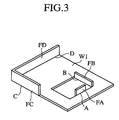
- FIG. 3 there is shown a case where bending of a product W1 having bent portions FA, FB, FC and FD bent along bend lines A, B, C and D is performed in the order of the bend lines D, C, A and B.
- a method for displaying the die layout in the display device 23 in such a case will be described below.
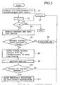
- step S1 When bending of the product W1 is performed, in step S1, the bend line D having a maximum bending length is retrieved from the data stored in the product processing data memory 37 for the product W1 and first dies (punch and die) P1 and D1 corresponding to the bend line D are displayed in the display device 23 (FIG.4A).
- step S2 a bending order 1 is set and in step S3, determination is made as to whether the last bending number of times has been reached or not and if YES, the process is finished.
- step S3 if the result of determination is NO, the diagram of the bending order set in step S2 and the length of the bend line are displayed between the die P1 and D1 (step S4).
- the dies P1 and D1 corresponding to the length of the bend line D are displayed along with the bend line D (FIG. 4A).
- step S5 by seeing the display of the dies P1 and D1 and the bend line D as shown in FIG. 4A, determination is made as to whether it is possible to perform bending along the bend line D or not. In this case, since there are no interferences between the dies P1 and D1 and the product W1 and bending along the bend line D can be performed, the process proceeds to step S6, where by operating the input device 25, the dies P1 and D1 are related to the bend line D and registered.
- step S7 the bend line C as the second in the bending order is displayed between the dies P1 and D1 (step S4, FIG. 4B).
- this bent portion FD since the bent portion FD has been created as a result of bending along the bend line D, this bent portion FD is displayed together.
- step S5 determination is made as to whether it is possible to perform bending along the bend line C or not.
- the diagram of the product W1 is moved in left and right directions by operating the input device 25 and in the position of the bent portion FD away from the ends of the dies P1 and D1 bending is permitted.
- the process then proceeds to step S6, where the dies are registered as in the previous case.
- step S8 by moving the diagram of the product W1 to a position away from the dies P1 and D1, data regarding new second dies P2 and D2 corresponding to the bend line A is read from the die data memory 39 and displayed (FIG.4C).
- step S9 determination is made as to whether it is possible to perform bending along the previous bend lines D and C with respect to the second dies P2 and D2. As the result of determination is NO, the process moves to step S7.
- the process is executed in order to perform bending along the bend line B as a fourth in the order.
- the diagram of the product W1 is displayed between the first dies P1 and D1 and determination is made as to whether it is possible to perform bending along the bend line B with the dies P1 and D1 or not. If the answer is NO, the diagram of the product W1 is moved to the positions of the second dies P2 and D2. If the result of determination is still NO even with the second dies P2 and D2, by further moving the diagram of the product W1 to the side, third dies P3 and D3 corresponding to the bend line 3 are displayed (step S8, FIG. 4D).
- step S9 the dies P3 and D3 are registered as in step S6 (step S9) and in step S10, determination is made as to whether it is possible to perform bending along the previous bend line D, C and A with these dies P3 and D3 or not.
- the bend lines D and C are longer than the bend line B and bending therealong is impossible.
- the diagram of the product W1 of FIG. 4C is displayed again corresponding to the third dies P3 and D3 and determination is made as to whether it is possible to perform bending along the bend line A with the third dies P3 and D3 or not. If YES, the process proceeds to step S11, where the second dies P2 and D2 are erased, the bend line A is related to the third dies P3 and D3 and a change is made to the registration.
- the dies needed for bending of the product W1 are laid out. This allows easy laying out of the dies.
- the invention provides a novel method for checking interferences. This method will be described hereinbelow.
- FIG.6 there are shown a display of the stereoscopic shape of a product W2 made in the display device based on stereoscopic graphical data regarding the product W2 stored in the product data memory 37 and a display of a cut line CL representing the cutting position of the product W2 therein.
- a cut edge shape can be obtained by moving the cut line CL to an optional position of the shape of product W2 stereoscopically displayed. Further, since this edge shape and those of the dies 41P and 41D are displayed together, a diagram displayed for interference checking can be made simple and the interference checking position of the product W2 and the existence of interferences between the product W2 and the dies can be easily found by eyes.
- step S20 three-dimensional data regarding a product W3 and a die 43 is fetched from the data memories 37 and 39 and in step S21, the product W3 and the die 43 are displayed in the display device 23.
- step S22 After the position to be checked for interferences of the product W3 and a sight line direction are indicated by, for instance arrows on the display screen (step S22), the shapes of the product W3 and the die 43 are displayed in the indicated sight line direction (step S23), the bending state of the product W3 is displayed (step S24) and determination may be made as to whether the cross-sectional area T based on the sum of the cross-sectional area of the indicated interference checking position W3C of the product W3 and the cross-sectional area of the die 43 is smaller than the sum of the fixed, independent cross-sectional area Q of the indicated interference W3C of the product W3 and the fixed, independent cross-sectional area R of the die 43 (step S25). If the calculated area T is smaller than the fixed sum of Q and R, then it can be determined that interference has occurred. On the contrary, if the calculated area T is not smaller than the fixed sum of Q and R, then it can be determined that no interference has occurred.
- the developments of a product and parts and the shape of the whole product may be displayed for bending of the long parts and product.
- the feature portions of the product may be displayed being crashed, making it impossible to accurately recognize the feature portions.
- the invention provides an approach to clear displaying of feature points regarding the product shapes and the developments even when the product is long.
- a video RAM 45 is connected to the controller 13.
- a development showing a long product W4 or its bend line is displayed in the display device 23, if its aspect ratio is big and its feature points are crashed, data regarding the shape of the long product W4 is fetched into the video RAM 45 and scanning performed in the longitudinal direction of the product W4 with specified pitches.
- the scanning pitch may be a fixed amount (e.g., based on a desired resolution) or may be variable with the detection and scanning of the feature portions of the part (i.e., a finer scanning pitch may be used to provide a higher resolution when scanning detailed or feature portions of the part).
- step S30 a first scanning line is set and in step S31, determination is made as to whether scanning has been completed over the entire area of the video RAM 45 or not. Then, in step S32, when the scanning line intersects the development including the bend line or the diagram of the product W4, coordinate data in a position orthogonal to the scanning direction is fetched and in step S33, determination is made as to whether the previous coordinate data and the current coordinate date are identical or not. If identical, the process proceeds to step S34, where the current coordinate data is omitted. Thereafter, the process continues to step S36 to increment to the next scanning line.
- step S35 the current coordinate data is temporarily registered in the RAM as the data adjacent to a previous registered data with respect to the longitudinal direction of the product W4.
- step S36 by incrementing the scanning line (i) and using a new scanning line, the process is repeated from step S31 to A36.
- step S37 the diagram is developed again based on the coordinate data registered in step S35.
- FIG.9B if a displayed diagram is small, by magnifying it by a desired amount, an expanded view like that shown in FIG. 9C is obtained.
- the product W4 can be displayed by shortening its longitudinal direction and expanding the view when necessary, making it possible to recognize the feature portions of the product W4 all at the same time. In other words, it is easy to confirm and understand all the feature portions of the product W4 , because not just one portion of the product W4 is expanded and displayed.
Description
- The present invention relates to a method for displaying a die layout in a press brake and to an apparatus for displaying a die layout in a press brake as defined in
claims - Conventionally, where lengths and shapes of a plurality of bent spots in a bent product are different from one another, a plurality of spots in a workpiece have often been bent in sequence with one press brake by loading and properly spacing a plurality of dies in the press brake.
- When a plurality of spots in a workpiece are to be bent by loading a plurality of dies in the press brake, the kinds and layout of the dies to be used are recorded in a work sheet so as to facilitate easy selection of the dies when bending of the same product is carried out again. However, this recording work is burdensome.
- For a new product, a worker must consider the kinds and arrangement of dies according to a bending sequence of the product. It was thus troublesome to select and arrange dies in accordance with bending of a new product.
- It is necessary to check interferences between a workpiece and dies for bending of the workpiece. Traditionally, it was rather difficult to see the workpiece and the dies, because they were stereoscopically shown in a display device.
- Furthermore, when the whole picture of the product and the workpiece was displayed, for instance where the workpiece was long, it was difficult to see the picture because of thin displaying of portions in the vicinity of end parts or feature sections.
- The present invention was made to solve to the above-noted problems, and the purpose of the present invention is to provide a press brake which allows easy selection and laying out of dies during bending of a product by detecting the kinds and layout of the dies loaded in the press brake, indication of the layout of the dies and the details of a workpiece and the product and checking of interference between the workpiece and the dies when the product is to be bent.
- According to the invention recited in
claim 1, a method for displaying die layout in the press brake is provided. The method is composed of the following steps: (a) displaying of a die corresponding to a maximum bending length of a product to be processed; (b) displaying of a diagram and a bend line of a bending sequence of the product to be processed corresponding to the displayed die; (c) determination as to whether or not it is possible to perform bending by moving the displayed diagram corresponding to the displayed die; (d) registration of the die if it is determined to be YES in step (c) and displaying of a new die corresponding to the length of a bend line if it is NO; (e) determination as to whether or not it is possible to replace the one for previous bending by the new die; and (f) changing of the registration by erasing the previous relevant die if it is determined to be YES in step (e), displaying again of the diagram for next bending by returning to step (b) if it is NO and completing the whole bending process. - According to the invention recited in
claim 5, a die layout display device is provided in the press brake, comprising a first storage part in which product processing data such as lengths of bending lines, bending sequences and dimensions of bending shapes are stored, a second storage part in which data regarding lengths and dimension of dies is stored, a display device controller for displaying workpiece shapes for each bending sequence by fetching the data from the first storage part and a die corresponding to the bending line length of the workpiece shown in the display device by fetching the dimension data of the die stored in the second storage part and a movement instructing device for providing an instruction to move the workpiece shown in the display device to the display device controller. - Preferably, a method for checking die interferences is provided in a system including a first memory in which stereoscopic graphic data of a product is stored, a second memory in which cross-sectional shape data of a die needed for bending of the product is stored, a display device and a display device controller. The method includes a step of fetching edge shape data of the designated cross-sectional position of the product stereoscopic shape shown in the display device from the first and second memories into the display device controller, and displaying the edge shape of the designated cross-sectional position of the product and the cross-sectional shape of the die in combination in the display device.
- The method for checking die interferences preferably comprises the steps of: fetching three-dimensional shape data of a die and a workpiece and displaying this in a display device; indicating a position for checking workpiece interferences and a sight line direction on a display screen; displaying the shapes of the die and the workpiece in the indicated sight line direction; performing virtual bending of the workpiece on the display screen; and determining whether the sum of the cross-sectional area of the workpiece in the indicated position and that of the die is larger than a fixed number or not, continuing the virtual bending process if its answer is YES, stopping the same if its answer is NO and performing checking of interferences.
- Preferably, the method for checking press brake interferences is provided. The method comprises the steps of: fetching three-dimensional data of an object to be interfered with and an object to be observed from a memory and displaying this in a display device; indicating a position of the observed object for performing interference checking and a sight line direction on a display screen; displaying the shapes of the interfered object and the observed object in the indicated sight line direction; moving the observed object toward the interfered object on the display screen; determining whether the sum of the cross-sectional area of the interfered object and that of the designated portion of the observed object is larger than a fixed number or not; and continuing the movement if the result of determination is YES, stopping the movement if NO and checking interferences.
- Moreover, preferably a method for displaying long parts by shortening the lengths thereof is provided. The method includes the steps of: displaying long parts in a display device; scanning the shapes of the displayed parts in the longitudinal direction thereof with specified pitches; determining whether coordinate data regarding a line position representing the shapes of the parts is the same as that during scanning of a previous time or not; omitting this data if the result of determination is YES or repeatedly registering the coordinate data if NO; and displaying the long parts by unfolding the registered coordinate data again after completion of scanning.
- Preferably, the method for displaying the long parts with the lengths made short as noted in the eight aspect of the invention further includes a step of displaying, when the long parts are to be displayed by unfolding the registered coordinate data again, the parts by magnifying these by a desired amount.
- Preferably, a press brake is provided, comprising a scanner for reading reference numbers and symbols given to dies loaded in the press brake and a position detecting device for detecting the moving position of the scanner.
- Preferably, the press brake of the first aspect of the invention is further provided with a memory for correlating position data detected by the position detecting device with data read by the scanner and storing these and a display device for displaying data stored in the memory.
-
- FIG.1 is a front view of a press brake.
- FIG.2 is a functional block diagram illustrating a structure of a controller of a press brake.
- FIG.3 is a stereoscopic diagram showing an example of a product.
- FIGs.4A-4E are views illustrating a method for displaying die layout.
- FIG.5 is a flow chart showing a method for displaying die layout.
- FIGs.6A and 6B are views illustrating a display part for checking interferences between a product and a die.
- FIG. 7 is a flow chart showing another method for checking interferences between a product and a die and a view illustrating the same.
- FIG.8 is a flow chart showing a case where a diagram, etc., of a long product are reduced in size in its longitudinal direction.
- FIGs.9A-9C are views illustrating a case where a diagram of a long product is reduced in size in its longitudinal direction, displayed by unfolding this again and displayed in an expanded manner.
- Referring to FIG.1, a
press brake 1 in an illustrated example is provided with an upper frame 3 and alower frame 5 placed oppositely to each other in upper and lower parts. Either the upper frame 3 or thelower frame 5 is provided as a movable frame so as to be movable in a vertical direction. A vertical motion actuating device (not shown), for instance a hydraulic cylinder or a servo motor, is also provided to move the movable frame up and down. - A plurality of
punches intermediate plates 7. A die 11 corresponding to one of thepunches 9A to 9D is attached to thelower frame 5. In the example, only onedie 11 is shown. In actuality, however, depending on the bending shapes of a workpiece (not shown in FIG. 1), a plurality of dies corresponding to therespective punches 9A to 9D are to be attached. - The
press brake 1 is further provided with acontroller 13, for instance an NC device or a small computer for controlling each controlled shaft of thepress brake 1. - The
controller 13 is, as shown in FIG. 2, provided with aCPU 15. TheCPU 15 is connected to aROM 17, aRAM 19, and adisplay device 23, for instance, a CRT via adisplay device controller 21 such as a CRT controller and the like. Aninput device 25, for instance a keyboard or a mouse, is also connected to theCPU 15 when necessary. -
Bar codes 27A to 27D of reference numbers and symbols representing data regarding thepunches 9A to 9D, including their shapes, dimensions, manufacturing dates and die numbers, are attached to thepunches 9A to 9D. In order to read thesebar codes 27A to 27D, ascanner 29 capable of moving in left and right directions, for instance an image pickup unit or a bar code scanner, is provided. - More particularly, in the example, the
scanner 29 is supported by aguide member 31 provided in the upper frame 3 in left and right directions so as to be movable in left and right directions. In order to detect the moving position of thescanner 29 in the left or the right direction, a linear scale, for instance a magnetic scale, is provided as aposition detecting device 33. - In the above-noted configuration, when the
scanner 29 is moved in left and right directions along theguide member 31, its moving position, for instance one from the reference position of a left edge, is detected by theposition detecting device 33 and when thescanner 29 comes to each of thebar codes 27A to 27D of thepunches 9A to 9D, each of the same is read. - Data regarding each of the
bar codes 27A to 27D read by thescanner 29 and detected position data detected by theposition detecting device 33 are correlated with product numbers by theCPU 15 in thecontroller 13 and stored in amemory 35. The data stored in thismemory 35 is displayed in thedisplay device 23 by retrieving the product number. - Therefore, after the plurality of
punches 9A to 9D and the plurality ofdies 11 are loaded in order to prepare for bending of a certain product, the arranged positions of the necessary punches and the respective punches can be detected by moving thescanner 29 in the left and right directions along theguide member 31 and reading thebar codes 27A to 27D attached to thepunches 9A to 9D. The position data of therespective punches 9A to 9D and data regarding die shapes , dimensions, etc., can be stored in thememory 35. - When the same product is to be bent again, the dies necessary for this work can be placed in the same positions again by reading data regarding the same product number from the
memory 35, displaying this in thedisplay device 23 or printing this by means of a printer, etc., and arranging the dies in accordance with this display or the print. As a result, when bending of the same product is repeated at an interval of some time, it is possible to improve work performance by quickly preparing the dies upon re-machining. - In the above example, the
scanner 29 was moved manually. However, the scanner can be configured to be moved automatically by using a ball screw mechanism, etc., rotated by the linear motor or the servo motor. In addition, the bar codes can be provided in the die 11 sides and the scanner can be provided in the lower side. - Furthermore, another way of configuration is possible, wherein the
controller 13 is properly connected to a host computer (not shown), the position data of the punches (dies) 9A to 9D and data regarding die shapes and dimensions are stored in the memory of the host computer, these data are read out to the controller provided in another press brake connected to the host computer and the position data of the dies (punches) 9A to 9D and the data regarding die shapes and dimensions are utilized in this press brake. This makes it possible to easily lay out the necessary dies when bending of the product bent once is to be performed again. - The
scanners 29 and others noted above are useful for detection of the arranged positions, shapes and dimensions of the dies loaded in the press brake. However, when a product is new, it is necessary to set anew the layout of the dies for bending of this product. - Thus, the
controller 13 in the example is provided with aproduct data memory 37 connected thereto for storing product processing data including bend line lengths, bending sequences, bent shapes and dimensions, product stereoscopic graphic data according to the bending sequence and the like. Adie data memory 39 for storing necessary die data including die shapes and dimensions is also connected to the controller. - The
product data memory 37 and thedie data memory 39 may be provided in the host computer. These can be configured to be placed in theRAM 19 of thecontroller 13 via communication means when necessary. In this case, it is possible to control a memory capacity to be small in thecontroller 13. - Referring to FIG. 3, there is shown a case where bending of a product W1 having bent portions FA, FB, FC and FD bent along bend lines A, B, C and D is performed in the order of the bend lines D, C, A and B. A method for displaying the die layout in the
display device 23 in such a case will be described below. - When bending of the product W1 is performed, in step S1, the bend line D having a maximum bending length is retrieved from the data stored in the product
processing data memory 37 for the product W1 and first dies (punch and die) P1 and D1 corresponding to the bend line D are displayed in the display device 23 (FIG.4A). - Then, in step S2, a
bending order 1 is set and in step S3, determination is made as to whether the last bending number of times has been reached or not and if YES, the process is finished. In step S3, if the result of determination is NO, the diagram of the bending order set in step S2 and the length of the bend line are displayed between the die P1 and D1 (step S4). - For the product W1 shown in FIG.3, since the longest is the bend line D and its bending order is first, the dies P1 and D1 corresponding to the length of the bend line D are displayed along with the bend line D (FIG. 4A).
- In step S5, by seeing the display of the dies P1 and D1 and the bend line D as shown in FIG. 4A, determination is made as to whether it is possible to perform bending along the bend line D or not. In this case, since there are no interferences between the dies P1 and D1 and the product W1 and bending along the bend line D can be performed, the process proceeds to step S6, where by operating the
input device 25, the dies P1 and D1 are related to the bend line D and registered. - Then, the process proceeds to step S7, where the bend line C as the second in the bending order is displayed between the dies P1 and D1 (step S4, FIG. 4B). In this case, since the bent portion FD has been created as a result of bending along the bend line D, this bent portion FD is displayed together.
- Then, in step S5, determination is made as to whether it is possible to perform bending along the bend line C or not. In this case, since there are interferences between the bent portion FD and the dies P1 and D1, the diagram of the product W1 is moved in left and right directions by operating the
input device 25 and in the position of the bent portion FD away from the ends of the dies P1 and D1 bending is permitted. The process then proceeds to step S6, where the dies are registered as in the previous case. - Then, since a third in the bending order is the bend line A, the bend line A is displayed between the dies P1 and D1 with the bent portions FD and FC bent (FIG. 4C), the diagram of the product W1 is moved in the left and right directions and determination is made as to whether it is possible to perform bending along the bend line A. In this case, since bending cannot be carried out, the process proceeds to step S8, where by moving the diagram of the product W1 to a position away from the dies P1 and D1, data regarding new second dies P2 and D2 corresponding to the bend line A is read from the
die data memory 39 and displayed (FIG.4C). - In this case, by using the second dies P2 and D2, it is possible to perform bending along the bend line A. Thus, the process proceeds to step S9, where these dies are registered as in step S6. Then, in step S10, determination is made as to whether it is possible to perform bending along the previous bend lines D and C with respect to the second dies P2 and D2. As the result of determination is NO, the process moves to step S7.
- Then, the process is executed in order to perform bending along the bend line B as a fourth in the order. The diagram of the product W1 is displayed between the first dies P1 and D1 and determination is made as to whether it is possible to perform bending along the bend line B with the dies P1 and D1 or not. If the answer is NO, the diagram of the product W1 is moved to the positions of the second dies P2 and D2. If the result of determination is still NO even with the second dies P2 and D2, by further moving the diagram of the product W1 to the side, third dies P3 and D3 corresponding to the bend line 3 are displayed (step S8, FIG. 4D).
- Thus, the dies P3 and D3 are registered as in step S6 (step S9) and in step S10, determination is made as to whether it is possible to perform bending along the previous bend line D, C and A with these dies P3 and D3 or not. In this case, the bend lines D and C are longer than the bend line B and bending therealong is impossible. However, since the bend line A is shorter than the bend line B, the diagram of the product W1 of FIG. 4C is displayed again corresponding to the third dies P3 and D3 and determination is made as to whether it is possible to perform bending along the bend line A with the third dies P3 and D3 or not. If YES, the process proceeds to step S11, where the second dies P2 and D2 are erased, the bend line A is related to the third dies P3 and D3 and a change is made to the registration.
- When the dies registered in the memory are displayed in the
display device 23 after repeating the above-noted operations, the layouts of the first dies P1 and D1 and the third dies P3 and D3 are displayed for the product W1 (FIG.4E). - Therefore, by loading the necessary dies in the press brake in accordance with the displays in the display device, the dies needed for bending of the product W1 are laid out. This allows easy laying out of the dies.
- In other words, even when a product targeted for bending is new, it is possible to lay out the dies relatively easily.
- As described above, when bending of a product is performed by placing a plurality of dies in the press brake, it is relatively easy to check interferences between the dies and the product if the shape of the product is relatively simple. As a method for carrying out checking of interferences between the product and the dies, one including the steps of stereoscopically displaying the product and the dies and displaying these by changing the colors of interfered portions may be considered. However, if the shape of the product is complex, it may be difficult to see the interfered portions. Also, it may be possible to carry out interference checking, for instance by displaying in combination the side view or the cross-sectional view of the product shape, the side view or the cross-sectional view of the dies. However, in the side and cross-sectional views, a side immediately before a portion targeted for interference checking is simultaneously displayed and thus, it may be difficult to see the interfered portion if the shape is complicated.
- In view of this, the invention provides a novel method for checking interferences. This method will be described hereinbelow.
- Referring to FIG.6, there are shown a display of the stereoscopic shape of a product W2 made in the display device based on stereoscopic graphical data regarding the product W2 stored in the
product data memory 37 and a display of a cut line CL representing the cutting position of the product W2 therein. There is also illustrated a display in combination of the edge shape of the product W2 cut along the cult line CL and the edge shapes of necessary dies 41P and 41D stored in thedie data memory 39 in thedisplay device 23. - In the above-noted configuration, a cut edge shape can be obtained by moving the cut line CL to an optional position of the shape of product W2 stereoscopically displayed. Further, since this edge shape and those of the dies 41P and 41D are displayed together, a diagram displayed for interference checking can be made simple and the interference checking position of the product W2 and the existence of interferences between the product W2 and the dies can be easily found by eyes.
- It is possible to adopt another approach to checking of interferences between dies and a product as described hereinbelow. Referring to FIG. 7, in step S20, three-dimensional data regarding a product W3 and a
die 43 is fetched from thedata memories display device 23. - Then, after the position to be checked for interferences of the product W3 and a sight line direction are indicated by, for instance arrows on the display screen (step S22), the shapes of the product W3 and the die 43 are displayed in the indicated sight line direction (step S23), the bending state of the product W3 is displayed (step S24) and determination may be made as to whether the cross-sectional area T based on the sum of the cross-sectional area of the indicated interference checking position W3C of the product W3 and the cross-sectional area of the die 43 is smaller than the sum of the fixed, independent cross-sectional area Q of the indicated interference W3C of the product W3 and the fixed, independent cross-sectional area R of the die 43 (step S25). If the calculated area T is smaller than the fixed sum of Q and R, then it can be determined that interference has occurred. On the contrary, if the calculated area T is not smaller than the fixed sum of Q and R, then it can be determined that no interference has occurred.
- Therefore, in step S25, if Q+R=T, then virtual bending is continued. However, if Q+R>T, then the process proceeds to step S26, where virtual bending is stopped and checking may be made on the interference position.
- Explanation was made of a case where interferences between the product and the dies are to be checked. In addition, it is possible to check interferences among the dies, the product and accessory devices by fetching data regarding the operations and shapes of such accessory devices as a robot, a manipulator and the like from a
memory 45, displaying the diagram of the accessory devices on thedisplay device 23 related to the product W3 and carrying out steps similar to steps S22 to S26 in the previous case. - Therefore, where a workpiece is to be supplied to the press brake by using a robot, etc., it is easy to check interferences between the robot and the dies, thereby preventing abutting of the robot against the dies.
- The developments of a product and parts and the shape of the whole product may be displayed for bending of the long parts and product. In this case, for example, if a product is long and its aspect ratio is extremely big, the feature portions of the product may be displayed being crashed, making it impossible to accurately recognize the feature portions.
- For this reason, as shown in the above example, the invention provides an approach to clear displaying of feature points regarding the product shapes and the developments even when the product is long.
- More particularly, a
video RAM 45 is connected to thecontroller 13. When a development showing a long product W4 or its bend line is displayed in thedisplay device 23, if its aspect ratio is big and its feature points are crashed, data regarding the shape of the long product W4 is fetched into thevideo RAM 45 and scanning performed in the longitudinal direction of the product W4 with specified pitches. - The scanning pitch may be a fixed amount (e.g., based on a desired resolution) or may be variable with the detection and scanning of the feature portions of the part (i.e., a finer scanning pitch may be used to provide a higher resolution when scanning detailed or feature portions of the part).
- That is, in step S30, a first scanning line is set and in step S31, determination is made as to whether scanning has been completed over the entire area of the
video RAM 45 or not. Then, in step S32, when the scanning line intersects the development including the bend line or the diagram of the product W4, coordinate data in a position orthogonal to the scanning direction is fetched and in step S33, determination is made as to whether the previous coordinate data and the current coordinate date are identical or not. If identical, the process proceeds to step S34, where the current coordinate data is omitted. Thereafter, the process continues to step S36 to increment to the next scanning line. - If the current coordinate data is determined not to be identical to the previous coordinate data in step S33, the process proceeds to step S35, where the current coordinate data is temporarily registered in the RAM as the data adjacent to a previous registered data with respect to the longitudinal direction of the product W4. Then, in step S36, by incrementing the scanning line (i) and using a new scanning line, the process is repeated from step S31 to A36. When scanning over the entire area of the
video RAM 45 is completed, the process proceeds to step S37, where the diagram is developed again based on the coordinate data registered in step S35. - As shown in FIG.9A, since a scanning line L4 intersects the diagram of the product W4 while scanning lines L1, L2 and L3 do not intersect this, a coordinate position in its intersecting location is fetched and temporarily registered in the
RAM 19. Then, a coordinate position in the intersection between a scanning line L5 and the diagram is fetched, compared with that for the scanning line L4 and registered in theRAM 19 because it is different. Further, scanning is carried out sequentially for scanning lines L6 and L5, L7 and L6 and L8 and L7, etc. , coordinate positions in locations crossing the diagram are compared for the respective cases and only the coordinate positions different from the previous are registered in theRAM 19 as the data adjacent to a previous registered data with respect to the longitudinal direction of the product W4. By transferring and storing the registered coordinate data from theRAM 19 into thevideo RAM 45, a view like that shown in FIG.9B is obtained - As shown in FIG.9B, if a displayed diagram is small, by magnifying it by a desired amount, an expanded view like that shown in FIG. 9C is obtained.
- Therefore, when the product W4 and its development is long, if the whole product is displayed with the feature portions crashed, according to the embodiment of the invention, the product W4 can be displayed by shortening its longitudinal direction and expanding the view when necessary, making it possible to recognize the feature portions of the product W4 all at the same time. In other words, it is easy to confirm and understand all the feature portions of the product W4 , because not just one portion of the product W4 is expanded and displayed.
- Explanation was made above of a case where scanning was carried out only in the left and right directions by referring to FIG. 9A. However, it is possible to shorten left and right directions and upper and lower directions by scanning in the upper and lower directions after completion of scanning in the left and right directions.
- Apparent from the foregoing, according to the embodiments of the invention, for bending of a product, it is possible to easily lay out the dies in the press brake and it is easy to fetch die layout with respect to the bent product and reproduce this.
- Furthermore, it is easy to check interferences between the product and the dies during bending and even when the product is long, it is easy to confirm and understand all the feature portions of the product.
Claims (5)
- A method for displaying a die layout in a press brake (1), said method comprising the steps of:(a) displaying, on a display device (23), at least one pair of dies (P1,D1) corresponding to a maximum bend line length of a product (W1) to be bent;(b) displaying, on said display device (23), a diagram and a bend line portion of said product (W1) in an order of bending corresponding to said displayed dies (P1,D1);(c) determining, based on said displayed diagram, said displayed bend line portion and said displayed dies (P1,D1), whether it is possible to perform a bending operation on said product (W1);(d) registering said displayed dies (P1,D1) if it is determined that said bending operation can be performed;(e) further displaying new dies (P2,D2) corresponding to a bend line length of said displayed bend line portion if it is determined that said bending operation cannot be performed, and registering said displayed new dies (P2,D2);(f) determining whether it is possible to replace previously registered dies (P1,D1) by said displayed new dies (P2,D2) for bending said product (W1);(g) changing the registration by erasing said previously registered dies (P1,D1) if it is determined that it is possible to replace the previously registered dies (P1,D1) with said displayed new dies (P2,D2), and(h) displaying a next diagram and bend line portion of said product for a next bending operation within said order of bending by returning to step (b) and repeating the process of steps (b) through (h) until all bending operations within said order of bending have been analyzed.
- A method according to claim 1, further comprising the step of selectively moving said displayed diagram said part relative to said displayed dies (P1,D1) when it is determined that said bending operation cannot be performed, said step of further displaying new dies (P2,D2) displaying said new dies (P2,D2) when said displayed diagram is moved away from said displayed dies (P1,D1).
- A method according to claim 1, wherein said step of determining whether it is possible to perform said bending operation comprises detecting whether there is an interference based on said displayed diagram and said displayed dies (P1,D1).
- A method according to claim 3, wherein said determining determines that said bending operation cannot be performed when an interference is detected.
- An apparatus for displaying a die layout in a press brake (1) comprising:a first storage part (37) for storing product processing data, said product processing data relating to bend line lengths, a bending order and bent shapes and dimensions relating to a product;a second storage part (39) for storing data relating to die lengths and dimensions;a display device controller (21) for displaying, on a display device (23), a representation of said product (W1) at each stage in said bending order by fetching data from said first storage part (37) and for displaying, on said display device (23), dies (P1,D1;P2,D2;P3,D3) corresponding to bend line lengths of said product (W) displayed in said display device (23) by fetching data regarding die dimensions from said second storage part (39), and displaying new dies corresponding to a bend line length of a displayed bend line being displayed if it is determined that the bending operation cannot be performed; anda movement instructing device for selectively providing, to said display device controller (21), an instruction to move said product (W1) displayed on said display device (23).
Applications Claiming Priority (5)
| Application Number | Priority Date | Filing Date | Title |
|---|---|---|---|
| US2135596P | 1996-07-08 | 1996-07-08 | |
| US21355P | 1996-07-08 | ||
| US832509 | 1997-04-02 | ||
| US08/832,509 US5983688A (en) | 1996-07-08 | 1997-04-02 | Method and apparatus for displaying die layout in press brake and for checking interference |
| EP97929559A EP0919300B1 (en) | 1996-07-08 | 1997-07-08 | Press brake with device for checking tool interferences |
Related Parent Applications (1)
| Application Number | Title | Priority Date | Filing Date |
|---|---|---|---|
| EP97929559A Division EP0919300B1 (en) | 1996-07-08 | 1997-07-08 | Press brake with device for checking tool interferences |
Publications (3)
| Publication Number | Publication Date |
|---|---|
| EP1510267A2 EP1510267A2 (en) | 2005-03-02 |
| EP1510267A3 EP1510267A3 (en) | 2005-03-16 |
| EP1510267B1 true EP1510267B1 (en) | 2006-11-15 |
Family
ID=26694587
Family Applications (2)
| Application Number | Title | Priority Date | Filing Date |
|---|---|---|---|
| EP04025205A Expired - Lifetime EP1510267B1 (en) | 1996-07-08 | 1997-07-08 | Method for displaying die layout in press brake and apparatus therefor |
| EP97929559A Expired - Lifetime EP0919300B1 (en) | 1996-07-08 | 1997-07-08 | Press brake with device for checking tool interferences |
Family Applications After (1)
| Application Number | Title | Priority Date | Filing Date |
|---|---|---|---|
| EP97929559A Expired - Lifetime EP0919300B1 (en) | 1996-07-08 | 1997-07-08 | Press brake with device for checking tool interferences |
Country Status (5)
| Country | Link |
|---|---|
| US (1) | US5983688A (en) |
| EP (2) | EP1510267B1 (en) |
| JP (3) | JP4279352B2 (en) |
| DE (2) | DE69736112T2 (en) |
| WO (1) | WO1998001243A1 (en) |
Cited By (1)
| Publication number | Priority date | Publication date | Assignee | Title |
|---|---|---|---|---|
| WO2015019285A1 (en) | 2013-08-09 | 2015-02-12 | Bystronic Laser Ag | Bending press |
Families Citing this family (30)
| Publication number | Priority date | Publication date | Assignee | Title |
|---|---|---|---|---|
| US6243619B1 (en) | 1996-05-10 | 2001-06-05 | Amada Company, Ltd. | Control method and apparatus for plate material processing machine |
| US6163734A (en) * | 1996-07-05 | 2000-12-19 | Amada Co Ltd | Punching tool provided with tool identification medium and punch press provided with a tool identification medium reader cross reference to related application |
| DE60044022D1 (en) * | 1999-01-13 | 2010-04-29 | Amada Co Ltd | BENDING PRESS SYSTEM |
| JP3790161B2 (en) * | 1999-07-13 | 2006-06-28 | 株式会社アマダエンジニアリングセンター | Sheet metal bending system and control data creation method thereof |
| CA2360301A1 (en) | 2001-10-26 | 2003-04-26 | Shearpress Sales Inc. | Apparatus and method for overcoming angular deviations in a workpiece |
| AT412453B (en) * | 2002-07-01 | 2005-03-25 | Trumpf Maschinen Austria Gmbh | MANUFACTURING DEVICE, IN PARTICULAR BUTTING PRESSURE, WITH ELECTRONIC TOOL CAPTURE |
| US6848290B2 (en) * | 2002-10-10 | 2005-02-01 | Pyper Tool & Engineering, Inc. | Stock lifter for metal forming dies and method for making the same |
| JP4630533B2 (en) * | 2002-10-23 | 2011-02-09 | 株式会社アマダ | Bending machine |
| US7773270B2 (en) * | 2004-01-07 | 2010-08-10 | Hewlett-Packard Development Company, L.P. | Image scanner feature detection |
| EP1834712A4 (en) * | 2004-11-17 | 2013-08-28 | Amada Co Ltd | Bending method, die and bending machine used for bending method |
| EP1925374B1 (en) | 2005-06-15 | 2014-05-21 | Amada Co., Ltd. | Bending device and method for managing die, method for arranging die and method for selecting die stocker |
| US7913533B2 (en) * | 2006-02-16 | 2011-03-29 | Wilson Tool International Inc. | Machine tool cartridge with information storage device, smart cartridge systems, and methods of using smart cartridge systems |
| US7669453B2 (en) * | 2006-02-16 | 2010-03-02 | Wilson Tool International Inc. | Cartridge for machine tool |
| DE102006020446A1 (en) * | 2006-05-03 | 2007-11-08 | Pass Stanztechnik Ag | Machining tool for machining workpiece has data unit with digitally readable storage medium containing data on measurements and type of tool |
| JP5108260B2 (en) * | 2006-07-06 | 2012-12-26 | 株式会社アマダ | Method and apparatus for utilizing bending machine mold layout |
| US7669446B2 (en) * | 2006-09-06 | 2010-03-02 | Edmund Burke, Inc. | Indexer for use with a sheet bending brake |
| JP5241330B2 (en) * | 2008-05-30 | 2013-07-17 | 株式会社アマダ | Robot bending apparatus and method |
| JP6334081B2 (en) * | 2012-02-27 | 2018-05-30 | 株式会社アマダホールディングス | Mold detection system and method |
| US9292811B2 (en) | 2012-11-30 | 2016-03-22 | Proper Group International | System and method for automated tool management |
| US10146976B2 (en) | 2012-03-01 | 2018-12-04 | Proper Digital LLC | Tooling system |
| US9740790B2 (en) | 2012-03-01 | 2017-08-22 | Proper Digital LLC | Tooling system |
| US9448650B2 (en) | 2012-11-09 | 2016-09-20 | Wilson Tool International Inc. | Display device for punching or pressing machines |
| JP6022324B2 (en) * | 2012-11-30 | 2016-11-09 | 株式会社日立製作所 | Use mold indicating apparatus and system in bending apparatus |
| CN104914738B (en) * | 2014-03-12 | 2018-06-01 | 佛山市恒力泰机械有限公司 | A kind of ceramic powder press human-computer interaction interface display methods |
| AT517706B1 (en) * | 2015-10-20 | 2017-04-15 | Trumpf Maschinen Austria Gmbh & Co Kg | bending machine |
| JP6322228B2 (en) * | 2016-06-08 | 2018-05-09 | 株式会社アマダホールディングス | Mold detection system and method |
| JP6867336B2 (en) * | 2018-07-17 | 2021-04-28 | ファナック株式会社 | Numerical control device |
| US11267036B2 (en) | 2018-12-27 | 2022-03-08 | Standard Lifters, Inc. | Stock lifter assembly |
| US11707775B2 (en) | 2018-12-27 | 2023-07-25 | Standard Lifters, Inc. | Stock lifter assembly |
| AT522518B1 (en) | 2019-05-10 | 2022-05-15 | Trumpf Maschinen Austria Gmbh & Co Kg | Method and system for optimizing the composition of bending tools of a bending machine |
Family Cites Families (20)
| Publication number | Priority date | Publication date | Assignee | Title |
|---|---|---|---|---|
| US4530148A (en) * | 1981-07-02 | 1985-07-23 | L. Schuler Gmbh | Tool changing mechanism |
| US4486840A (en) * | 1981-10-14 | 1984-12-04 | Houdaille Industries, Inc. | Computer numeric control for metal forming |
| JPS58149576A (en) * | 1982-02-27 | 1983-09-05 | Fanuc Ltd | System for figure input |
| US4633720A (en) * | 1984-12-17 | 1987-01-06 | Dybel Frank Richard | Load monitoring system for progressive dies |
| US4812985A (en) * | 1986-09-15 | 1989-03-14 | Ja-Pac, Inc | Article storage and retrieval system |
| JPH0732933B2 (en) * | 1986-12-16 | 1995-04-12 | 株式会社アマダ | Bending die automatic selection method |
| JPS63101022A (en) * | 1987-08-28 | 1988-05-06 | Anritsu Corp | Drawing method for sheet development |
| GB2211002B (en) * | 1987-12-15 | 1992-01-08 | Amada Co Ltd | Device and method for controlling a manipulator for a plate bending machine |
| JPH01271013A (en) * | 1988-04-23 | 1989-10-30 | Matsushita Electric Works Ltd | Bending angle control device for press brake |
| SE506952C2 (en) * | 1988-08-05 | 1998-03-09 | Amada Co Ltd | Method and apparatus for setting a bending process, and a method for preparing bending data |
| DE3830488A1 (en) * | 1988-09-08 | 1990-03-15 | Fastenrath Fasti Werk | Electronic tool-recognition system for press brakes |
| JPH0399730A (en) * | 1989-09-14 | 1991-04-24 | Komatsu Ltd | Data registering device for press die |
| JPH0744329Y2 (en) * | 1990-02-23 | 1995-10-11 | 株式会社小松製作所 | Device for detecting die interference area of press brake |
| JP2510371Y2 (en) * | 1990-06-07 | 1996-09-11 | 株式会社アマダ | Press brake |
| JPH05104169A (en) * | 1991-10-16 | 1993-04-27 | Komatsu Ltd | Method for checking interference with die |
| US5419169A (en) * | 1992-04-07 | 1995-05-30 | Toyota Jidosha Kabushiki Kaisha | Method and apparatus for adjusting press operating conditions depending upon dies used |
| JP2689855B2 (en) * | 1993-05-25 | 1997-12-10 | トヨタ自動車株式会社 | Air pressure setting method and device for die cushion device |
| JPH0756614A (en) * | 1993-08-13 | 1995-03-03 | Sanyo Electric Co Ltd | Automatic nc data generating device for sheet metal parts |
| JP3518883B2 (en) * | 1993-10-19 | 2004-04-12 | 株式会社小松製作所 | Die management method in punch press machine |
| DE4442381A1 (en) * | 1994-11-29 | 1996-05-30 | Gerd Ising | Device to read off type and position of tool in bending machine |
-
1997
- 1997-04-02 US US08/832,509 patent/US5983688A/en not_active Expired - Fee Related
- 1997-07-08 WO PCT/JP1997/002362 patent/WO1998001243A1/en active IP Right Grant
- 1997-07-08 EP EP04025205A patent/EP1510267B1/en not_active Expired - Lifetime
- 1997-07-08 JP JP50506098A patent/JP4279352B2/en not_active Expired - Fee Related
- 1997-07-08 EP EP97929559A patent/EP0919300B1/en not_active Expired - Lifetime
- 1997-07-08 DE DE69736112T patent/DE69736112T2/en not_active Expired - Fee Related
- 1997-07-08 DE DE69736962T patent/DE69736962T2/en not_active Expired - Fee Related
-
2007
- 2007-06-21 JP JP2007163776A patent/JP4413948B2/en not_active Expired - Fee Related
- 2007-06-21 JP JP2007163779A patent/JP4398490B2/en not_active Expired - Fee Related
Cited By (2)
| Publication number | Priority date | Publication date | Assignee | Title |
|---|---|---|---|---|
| WO2015019285A1 (en) | 2013-08-09 | 2015-02-12 | Bystronic Laser Ag | Bending press |
| US10189068B2 (en) | 2013-08-09 | 2019-01-29 | Bystronic Laser Ag | Bending press |
Also Published As
| Publication number | Publication date |
|---|---|
| DE69736112T2 (en) | 2006-10-19 |
| JP4413948B2 (en) | 2010-02-10 |
| EP0919300A4 (en) | 2001-03-21 |
| JP2008006503A (en) | 2008-01-17 |
| US5983688A (en) | 1999-11-16 |
| DE69736962T2 (en) | 2007-09-13 |
| EP0919300B1 (en) | 2006-06-14 |
| JP2008006504A (en) | 2008-01-17 |
| WO1998001243A1 (en) | 1998-01-15 |
| DE69736112D1 (en) | 2006-07-27 |
| EP1510267A2 (en) | 2005-03-02 |
| EP1510267A3 (en) | 2005-03-16 |
| EP0919300A1 (en) | 1999-06-02 |
| DE69736962D1 (en) | 2006-12-28 |
| JP4398490B2 (en) | 2010-01-13 |
| JP4279352B2 (en) | 2009-06-17 |
Similar Documents
| Publication | Publication Date | Title |
|---|---|---|
| EP1510267B1 (en) | Method for displaying die layout in press brake and apparatus therefor | |
| US6236399B1 (en) | Display method for information setting screen along process flow and a multi-window type NC apparatus having such function | |
| EP0172368B1 (en) | Method for displaying an image | |
| US6038899A (en) | Method of bending operations and bending system using the same | |
| US6535787B1 (en) | Control method and apparatus for plate material processing machine | |
| US6968080B2 (en) | Method and apparatus for generating part programs for use in image-measuring instruments, and image-measuring instrument and method of displaying measured results therefrom | |
| US20050096892A1 (en) | Simulation apparatus | |
| EP0558030B1 (en) | Coordinate system display guide for a numerical control apparatus | |
| JP2000074661A (en) | Measuring path selecting method in measuring instrument | |
| JP2624514B2 (en) | Method and apparatus for setting bending mold and bending order | |
| KR100355366B1 (en) | Character Information Processing Device | |
| EP1048995A2 (en) | Method of displaying images with a touchpanel for a molded form-take out robot | |
| EP0548372A1 (en) | Animation drawing method for multiple-lathe numeric controller | |
| US4644367A (en) | Recording pen apparatus | |
| JP3803428B2 (en) | Position setting device for movable member in plate processing machine | |
| JPH0732933B2 (en) | Bending die automatic selection method | |
| JPH11221630A (en) | Die attaching method in plate stock working machine and its device, die attaching position indicator, and manufacture of its indicator and its device | |
| EP2118618A1 (en) | Method for determining measuring points | |
| JP3847946B2 (en) | How to create a measurement result file for an image measuring machine | |
| JP2937918B2 (en) | Image measuring device | |
| JPH0246923A (en) | Method and device for setting process for bending machine | |
| JP2003181699A (en) | Ram operation pattern setting system for press machine | |
| JPS6336251A (en) | Forming device for original sticking sheet for scanner | |
| JPH05104169A (en) | Method for checking interference with die | |
| GB2401018A (en) | Image measuring instrument and method of displaying measured results therefrom |
Legal Events
| Date | Code | Title | Description |
|---|---|---|---|
| PUAI | Public reference made under article 153(3) epc to a published international application that has entered the european phase |
Free format text: ORIGINAL CODE: 0009012 |
|
| PUAL | Search report despatched |
Free format text: ORIGINAL CODE: 0009013 |
|
| AC | Divisional application: reference to earlier application |
Ref document number: 0919300 Country of ref document: EP Kind code of ref document: P |
|
| AK | Designated contracting states |
Kind code of ref document: A2 Designated state(s): DE FR GB IT NL |
|
| AK | Designated contracting states |
Kind code of ref document: A3 Designated state(s): DE FR GB IT NL |
|
| 17P | Request for examination filed |
Effective date: 20050708 |
|
| AKX | Designation fees paid |
Designated state(s): DE FR GB IT NL |
|
| GRAP | Despatch of communication of intention to grant a patent |
Free format text: ORIGINAL CODE: EPIDOSNIGR1 |
|
| GRAS | Grant fee paid |
Free format text: ORIGINAL CODE: EPIDOSNIGR3 |
|
| GRAA | (expected) grant |
Free format text: ORIGINAL CODE: 0009210 |
|
| AC | Divisional application: reference to earlier application |
Ref document number: 0919300 Country of ref document: EP Kind code of ref document: P |
|
| AK | Designated contracting states |
Kind code of ref document: B1 Designated state(s): DE FR GB IT NL |
|
| REG | Reference to a national code |
Ref country code: GB Ref legal event code: FG4D |
|
| REF | Corresponds to: |
Ref document number: 69736962 Country of ref document: DE Date of ref document: 20061228 Kind code of ref document: P |
|
| ET | Fr: translation filed | ||
| PLBE | No opposition filed within time limit |
Free format text: ORIGINAL CODE: 0009261 |
|
| STAA | Information on the status of an ep patent application or granted ep patent |
Free format text: STATUS: NO OPPOSITION FILED WITHIN TIME LIMIT |
|
| 26N | No opposition filed |
Effective date: 20070817 |
|
| PGFP | Annual fee paid to national office [announced via postgrant information from national office to epo] |
Ref country code: DE Payment date: 20080829 Year of fee payment: 12 |
|
| PGFP | Annual fee paid to national office [announced via postgrant information from national office to epo] |
Ref country code: FR Payment date: 20080722 Year of fee payment: 12 Ref country code: IT Payment date: 20080724 Year of fee payment: 12 Ref country code: NL Payment date: 20080724 Year of fee payment: 12 |
|
| PGFP | Annual fee paid to national office [announced via postgrant information from national office to epo] |
Ref country code: GB Payment date: 20080723 Year of fee payment: 12 |
|
| GBPC | Gb: european patent ceased through non-payment of renewal fee |
Effective date: 20090708 |
|
| NLV4 | Nl: lapsed or anulled due to non-payment of the annual fee |
Effective date: 20100201 |
|
| REG | Reference to a national code |
Ref country code: FR Ref legal event code: ST Effective date: 20100331 |
|
| PG25 | Lapsed in a contracting state [announced via postgrant information from national office to epo] |
Ref country code: FR Free format text: LAPSE BECAUSE OF NON-PAYMENT OF DUE FEES Effective date: 20090731 |
|
| PG25 | Lapsed in a contracting state [announced via postgrant information from national office to epo] |
Ref country code: GB Free format text: LAPSE BECAUSE OF NON-PAYMENT OF DUE FEES Effective date: 20090708 |
|
| PG25 | Lapsed in a contracting state [announced via postgrant information from national office to epo] |
Ref country code: DE Free format text: LAPSE BECAUSE OF NON-PAYMENT OF DUE FEES Effective date: 20100202 |
|
| PG25 | Lapsed in a contracting state [announced via postgrant information from national office to epo] |
Ref country code: IT Free format text: LAPSE BECAUSE OF NON-PAYMENT OF DUE FEES Effective date: 20090708 |
|
| PG25 | Lapsed in a contracting state [announced via postgrant information from national office to epo] |
Ref country code: NL Free format text: LAPSE BECAUSE OF NON-PAYMENT OF DUE FEES Effective date: 20100201 |