EP1505362B1 - Measuring probe with modules - Google Patents
Measuring probe with modules Download PDFInfo
- Publication number
- EP1505362B1 EP1505362B1 EP04077945.6A EP04077945A EP1505362B1 EP 1505362 B1 EP1505362 B1 EP 1505362B1 EP 04077945 A EP04077945 A EP 04077945A EP 1505362 B1 EP1505362 B1 EP 1505362B1
- Authority
- EP
- European Patent Office
- Prior art keywords
- stylus
- transducer
- module
- housing
- stylus holder
- Prior art date
- Legal status (The legal status is an assumption and is not a legal conclusion. Google has not performed a legal analysis and makes no representation as to the accuracy of the status listed.)
- Expired - Lifetime
Links
Images
Classifications
-
- G—PHYSICS
- G01—MEASURING; TESTING
- G01B—MEASURING LENGTH, THICKNESS OR SIMILAR LINEAR DIMENSIONS; MEASURING ANGLES; MEASURING AREAS; MEASURING IRREGULARITIES OF SURFACES OR CONTOURS
- G01B5/00—Measuring arrangements characterised by the use of mechanical techniques
- G01B5/004—Measuring arrangements characterised by the use of mechanical techniques for measuring coordinates of points
- G01B5/008—Measuring arrangements characterised by the use of mechanical techniques for measuring coordinates of points using coordinate measuring machines
- G01B5/012—Contact-making feeler heads therefor
-
- G—PHYSICS
- G01—MEASURING; TESTING
- G01B—MEASURING LENGTH, THICKNESS OR SIMILAR LINEAR DIMENSIONS; MEASURING ANGLES; MEASURING AREAS; MEASURING IRREGULARITIES OF SURFACES OR CONTOURS
- G01B11/00—Measuring arrangements characterised by the use of optical techniques
- G01B11/002—Measuring arrangements characterised by the use of optical techniques for measuring two or more coordinates
- G01B11/005—Measuring arrangements characterised by the use of optical techniques for measuring two or more coordinates coordinate measuring machines
- G01B11/007—Measuring arrangements characterised by the use of optical techniques for measuring two or more coordinates coordinate measuring machines feeler heads therefor
-
- Y—GENERAL TAGGING OF NEW TECHNOLOGICAL DEVELOPMENTS; GENERAL TAGGING OF CROSS-SECTIONAL TECHNOLOGIES SPANNING OVER SEVERAL SECTIONS OF THE IPC; TECHNICAL SUBJECTS COVERED BY FORMER USPC CROSS-REFERENCE ART COLLECTIONS [XRACs] AND DIGESTS
- Y10—TECHNICAL SUBJECTS COVERED BY FORMER USPC
- Y10S—TECHNICAL SUBJECTS COVERED BY FORMER USPC CROSS-REFERENCE ART COLLECTIONS [XRACs] AND DIGESTS
- Y10S33/00—Geometrical instruments
- Y10S33/03—Photoelectric
Definitions
- the present invention relates to a measuring probe, also known as an analogue or proportional probe, and which may, for example, be used on a coordinate positioning machine, such as a coordinate measuring machine or machine tool, in order to measure the shape, form, or dimensions of an object.
- a measuring probe also known as an analogue or proportional probe
- a coordinate positioning machine such as a coordinate measuring machine or machine tool
- a measuring probe typically includes a relatively fixed structure, which usually has the form of a housing, and a relatively movable structure the function of which is to retain a workpiece-contacting stylus, and is therefore frequently known as a stylus holder.
- the stylus holder is suspended within the housing by a mechanism which provides relative motion of one relative to the other. Relative displacement of the stylus holder and housing, (and therefore changes in relative displacement during relative motion) is detectable by one or more transducers, which are usually mounted to, or otherwise provided within the housing of the probe.
- the probe and a workpiece under inspection are mounted to relatively movable parts of the machine (the probe being mounted to the machine by the housing, thus enabling the stylus to move freely), and the machine is operated to bring the stylus into contact with a surface of the object in respect of which form, dimension, or contour information is required. Whilst the stylus is in contact with the surface, the transducer outputs from the probe are directly indicative of the relationship between the part of the machine upon which the probe is mounted and the surface under inspection. The position of a point upon the surface relative to a fixed reference point on the machine may thus be determined from signals indicative of the relative position of the two relatively movable parts of the machine, and the transducer outputs of the probe.
- analogue probe has a housing relative to which a stylus holder is suspended by a mechanism which includes a first flexible diaphragm connecting stylus holder to an intermediate member, which is then in turn connected to the housing via two further mutually parallel flexible diaphragms.
- a similar design of probe is disclosed in EP0426492 .
- Both prior art configurations of probe provide releasable mounting of a stylus to the stylus holder by means of magnets and mutually engageable elements forming a repeatable kinematic location. This enables a user to alter the configuration of stylus in dependence upon a particular inspection task to be undertaken with the probe.
- EP0501710 relates to a touch probe comprising a sensing module and a releasable stylus module containing a stylus over-travel mechanism. Measuring probes comprising overtravel mechanisms are also described.
- the present invention provides a modular configuration of probe, in which the suspension mechanism connecting the stylus holder to the housing is provided within a suspension module that is releasably and repeatably connectable to a transducer module containing one or more sensors of the probe transducers.
- one configuration of stylus may be exchanged for another by exchanging the suspension module.
- the mutually engageable elements locating the suspension module on the transducer module are situated on the housing of the suspension module and transducer module respectively, rather than on the stylus holder as is the case in the prior art, the inertial mass carried by the suspension mechanism is reduced. In this way the sensitivity of the probe is increased.
- a measuring probe according to the invention is defined in claim 1.
- Any suitable suspension mechanism may be provided within the suspension module, such as, for example, a series of parallel leaf springs, as disclosed in US Patent No. 4,084,323 , a series of linear bearings as disclosed in US Patent No. 5,088,208 , an assembly of linkages, each of which is connected both to the stylus holder and the housing as shown in US Patent No. 4,523,383 , or one or more flexible diaphragms, such as disclosed, for example in US Patent No. 5,345,689 (a family document of EP 0 544 854 ) or US Patent No. 4,158,919 .
- a series of parallel leaf springs as disclosed in US Patent No. 4,084,323
- a series of linear bearings as disclosed in US Patent No. 5,088,208
- an assembly of linkages each of which is connected both to the stylus holder and the housing as shown in US Patent No. 4,523,383
- one or more flexible diaphragms such as disclosed, for example in US Patent No. 5,345,
- a measuring probe may comprise a housing having an axis, a stylus holder extending along the axis and to which a stylus is connectable, and a suspension system for the stylus holder, wherein the suspension system comprises at least a pair of substantially planar diaphragms connected between the stylus holder and the housing and lying in first and second parallel planes orthogonal to, and spaced apart along, the axis, both of said diaphragms allowing limited axial movement of the stylus holder, and at least one of the diaphragms being sufficiently flexible in its plane to allow limited transverse movement of the stylus holder in the plane of said at least one diaphragm.
- one or more channels are provided through the respective diaphragms.
- the diaphragms are identical and the channels are of a substantially spiral configuration, each diaphragm having three such channels circumferentially offset by 120°.
- the stylus holder is displaced relative to the housing, upon the application of a force to the stylus, either linearly in the direction of the probe axis, or in a tilting manner, in planes substantially transverse to the probe axis. Detection of the linear axial displacement and the tilting displacement of the stylus holder will provide an indication of the position of the stylus sensing tip, for a given length of stylus. Because the suspension mechanism provides tilting action, different lengths of styli will produce, for a given linear deflection transverse to the axis at the stylus tip, a different degree of tilting of the stylus holder relative to the probe housing. Typically this is taken into account by calibration of the machine upon which the probe is to be used.
- the transducer system used may be configured to compensate for different lengths of stylus producing different tilting angles for a given displacement transverse to the axis at the stylus tip.
- the transducer system used is preferably an optical system which includes a light source which emits a beam of light incident upon an optical feature mounted to the stylus holder, which light beam is then passed on to a photosensitive detector that generates an output in dependence upon the incident position of the light beam on its photosensitive surface.
- the optical feature is preferably provided by a reflective or refractive element that interacts with an incident beam to reflect or refract the beam upon interaction with the feature by an angle determined by one or more optical parameters of the feature.
- a reflective or refractive element that interacts with an incident beam to reflect or refract the beam upon interaction with the feature by an angle determined by one or more optical parameters of the feature.
- the optical feature is provided by a mirror whose curvature is dependent upon the stylus length: longer stylus lengths having a greater curvature of the mirror in order to ensure that a smaller tilting displacement produces the same deflected angle by virtue of reflection of the incident light beam at the curved mirror.
- the optical feature is provided by a Fresnel lens, for example.
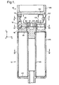
- a measuring probe includes a transducer module 10 upon which a suspension module 12 is releasably and repeatably mountable.
- the transducer and suspension modules 10,12 each have a relatively fixed structure provided by housings 14a and 14b respectively. Releasable mounting of the suspension module 12 upon the transducer module 10 takes place by virtue of mutually engageable location elements provided in the form of balls 16 on the transducer module housing 14a engageable within vee grooves 18 on the suspension module housing 14b, together with magnets 20 on the housings 14a and 14b which urge the location elements 16,18 into engagement.
- the housings 14a and 14b effectively act as a single relatively fixed housing structure.
- the suspension module 12 carries an elongate and relatively rigid stylus holder 40, which is suspended relative to the housing 14b by a pair of axially spaced substantially planar diaphragms 42,44. Because the connections between the two modules are on the housing parts, the suspension module carries only the stylus holder and stylus. By this means the mass on the suspension system is reduced for increased sensitivity.
- the stylus holder 40 is connected to the diaphragms substantially at their centre, and the housing 14b is connected to the diaphragms at their periphery.
- the pivoting motion of the stylus holder takes place about a point which, depending on the relative stiffnesses of the two diaphragms, may be positioned in the plane of either of the diaphragms, or at any axial position between the two.
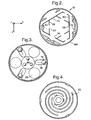
- each of the diaphragms 42,44 is cut through by three spiral channels 50, circumferentially offset at 120°.
- the channels have the effect of reducing the stiffness of the diaphragms 42,44 sufficiently to allow limited transverse movement of the stylus holder in their plane. It is thus possible for the stylus holder to pivot relative to the housing 14b about either the x or y axes, and also to translate relative to the housing 14b along the z axis.
- the pivoting motion in this embodiment will take place about a point on the axis mid-way between the planes of the two diaphragms.
- the use of the pair of transversely flexible diaphragms provides a simple inexpensive stylus mounting of high sensitivity. This type of mounting can be designed to have a low spring rate for low scanning forces.
- both diaphragms are relatively flexible
- a third diaphragm axially spaced mid-way between the two diaphragms 142,144, and which is stiff in its own plane to prevent transverse movement of the stylus holder in this plane while allowing pivoting of the stylus holder about the centre of the diaphragm.
- the advantages of the addition of the third diaphragm are that it adds to the structural stiffness of the spring combination and maintains a high natural frequency of vibration of the combination.
- the total spring rate can still be kept relatively low so as not to significantly increase the scanning forces.
- one of the diaphragms preferably the lower diaphragm 44, is designed to be stiff in its plane, sufficiently to prevent any transverse movement of the stylus holder in that plane, and the other diaphragm 42, is designed to be flexible in its plane to allow limited transverse movement of the stylus holder in that plane.
- the stylus holder pivots about the centre of the diaphragm 44 when a transverse force is applied to the stylus tip in the x,y plane.
- the suspension module By appropriate selection of the axial separation of diaphragms 42,44 in relation to their stiffness in the xy plane, it is also possible to configure the suspension module such that, for a given length of stylus connected to the stylus holder 40, substantially equal forces are required to deflect the stylus tip by the same amount in the xy plane and along the z axis.
- a shuttering member 60 is rigidly mounted to the stylus holder 40 in the sense that when the suspension module 12 is mounted to the transducer module 10, the shutter member 60 and the stylus holder 40 move in unison.
- the shutter member 60 has a substantially triangular configuration, and carries, at each of its vertices, a light source 62 (only one of which is shown in Fig 2 ). Light from the source 62 passes through a cavity 64 provided in a screen 66, (the purpose of which is to prevent cross-talk between individual transducers), and then through a relatively narrow axially extending slit 68.
- the magnitude of the output from the position sensitive detector 70 is thus indicative of the displacement in the y direction of the stylus holder 40.
- Two other transducers are provided, one of which has a further axially extending slit 72 to enable an indication of the displacement of the stylus holder in the x direction, and the other of which has a slit 74 which extends substantially in the xy plane in order to provide an indication of displacement of the stylus holder 40 in the axial or z direction.
- the stylus holder 40 is disengageable from the shuttering member 60, in order to permit the exchange of modules.
- connection between the stylus holder 40 and the shuttering member is provided by three balls 80 on the stylus holder 40, each of which is engageable within a vee groove 82 provided at the base of the shuttering member.
- Magnets 84,86 urge the balls 80 into engagement within the vee grooves thereby to provide repeatable location of the shuttering member 60 upon the stylus holder 40 from one exchange of a given suspension module 12 to another.
- the shuttering member 60 may be mounted rigidly to the stylus holder 40, such that a shuttering member is exchanged integrally with a suspension module.
- the light sources for the transducers would be mounted upon the housing 14a of the transducer module, and the shuttering member 60 would thus serve only to provide the optical features (in the form of the slits) necessary for operation of the transducer in question.
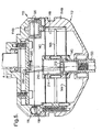
- a further embodiment of measuring probe is illustrated in Fig 5 , and includes a transducer module 110 upon which a suspension module 112 may be repeatably and releasably mounted by means of balls 116 on the transducer module housing 114a, urged into engagement with vee grooves 118 on the suspension module housing 114b by means of magnets 120.
- a stylus holder 140 is suspended relative to the suspension module housing 114b by a pair of planar axially spaced diaphragms 142,144 which have a configuration substantially as illustrated in Fig 4 of the previous embodiment.
- the diaphragms are prevented from overstressing during connection of a stylus 150 to the stylus holder (which connection is typically made by screw-threaded engagement) by virtue of a pair of protective arms 146, which extend substantially radially with respect to the probe axis A, and are connected rigidly to the stylus holder 140.
- the distal ends of the arms 146 extend into slots 148 provided in the housing 114b of the suspension module with a small clearance.
- the arms 146 do not come into contact with the sides of the slots 148, and suspension of the stylus holder 140 with respect to the housing 114b is undertaken exclusively by the diaphragms 142,144.
- the diaphragms 142,144 initially undergo a small circumferential deflection with respect to the axis A, until the clearance between the distal ends of the arms 146 within the slots 148 is taken up, whereupon the torque applied to the stylus holder 140 is transmitted via the arms into the housing 114b.
- the diaphragms 142,144 are protected from undergoing damage due to excess torque.
- Optical transducers are provided for detecting displacement of the stylus holder 140 relative to the fixed structure provided by the rigidly but releasably connected housings 114a,114b.
- each transducer includes a laser diode light source 200 which projects a beam 210 upon an optical feature, such as a mirror or a Fresnel lens 212 which is situated within a cavity 214 at the top of the stylus holder 140.
- an optical feature such as a mirror or a Fresnel lens 212 which is situated within a cavity 214 at the top of the stylus holder 140.
- Light reflected off the optical feature 212 is incident upon a position sensitive detector 220, the output of which is indicative of the incident position of the reflected light, and therefore of the displacement of the stylus holder relative to the fixed structure of the probe.
- the output from the transducers 220 will differ, for a given displacement of the stylus tip in the xy plane depending upon the length of the stylus.
- an optical feature 212 such as an appropriately curved mirror, or a Fresnel lens having an appropriate refractive power, such that differing lengths of styli produce substantially the same output at the transducer 220 for the same displacement of the stylus tip in the xy plane.
- the optical feature may be provided upon the upper surface of the stylus 150, which is configured to extend further into the housing 114b.
- a further independent aspect of the present invention thus provides an elongate stylus for a measuring probe having an optical feature suitable for use with a transducer, the feature being provided on the end of the stylus remote from the tip, and having one or more optical characteristics dependent upon the length of the stylus.
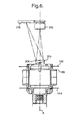
- FIG. 6 illustrates part of a probe of similar construction to that shown in Fig 5 .
- Components which are identical to those of Fig 5 are given the same reference numerals.
- the stylus holder 140 is supported from the housing of the probe (not shown) by a pair of diaphragms 142,144, both of which are of the type shown in Fig 4 .
- the optical transducers in this embodiment consist of two side-by-side focusing mirrors 312,314 tilted at opposite small angles to each other, and two side-by-side light sources 316 providing light beams aimed at the mirrors (only one of which is shown). Light reflected from the mirrors is directed onto side-by-side position sensitive detectors 318.
- tilting of the stylus holder due to x or y deflections of the stylus tip will cause x or y movements of the focused spots on the detectors, and axial movements of the stylus will cause simultaneous x and/or y movements of the two focused spots on the detectors.
- Algorithms derived from calibration of the probe transducer system enable deflections of the stylus to be determined from the detector outputs.
Description
- The present invention relates to a measuring probe, also known as an analogue or proportional probe, and which may, for example, be used on a coordinate positioning machine, such as a coordinate measuring machine or machine tool, in order to measure the shape, form, or dimensions of an object.
- A measuring probe typically includes a relatively fixed structure, which usually has the form of a housing, and a relatively movable structure the function of which is to retain a workpiece-contacting stylus, and is therefore frequently known as a stylus holder. The stylus holder is suspended within the housing by a mechanism which provides relative motion of one relative to the other. Relative displacement of the stylus holder and housing, (and therefore changes in relative displacement during relative motion) is detectable by one or more transducers, which are usually mounted to, or otherwise provided within the housing of the probe.
- In use, the probe and a workpiece under inspection are mounted to relatively movable parts of the machine (the probe being mounted to the machine by the housing, thus enabling the stylus to move freely), and the machine is operated to bring the stylus into contact with a surface of the object in respect of which form, dimension, or contour information is required. Whilst the stylus is in contact with the surface, the transducer outputs from the probe are directly indicative of the relationship between the part of the machine upon which the probe is mounted and the surface under inspection. The position of a point upon the surface relative to a fixed reference point on the machine may thus be determined from signals indicative of the relative position of the two relatively movable parts of the machine, and the transducer outputs of the probe.
- One known form of analogue probe is disclosed in
EP0544854 , and has a housing relative to which a stylus holder is suspended by a mechanism which includes a first flexible diaphragm connecting stylus holder to an intermediate member, which is then in turn connected to the housing via two further mutually parallel flexible diaphragms. A similar design of probe is disclosed inEP0426492 . Both prior art configurations of probe provide releasable mounting of a stylus to the stylus holder by means of magnets and mutually engageable elements forming a repeatable kinematic location. This enables a user to alter the configuration of stylus in dependence upon a particular inspection task to be undertaken with the probe. - Other types of probes, such as touch probes, are known.
EP0501710 relates to a touch probe comprising a sensing module and a releasable stylus module containing a stylus over-travel mechanism. Measuring probes comprising overtravel mechanisms are also described. - The present invention provides a modular configuration of probe, in which the suspension mechanism connecting the stylus holder to the housing is provided within a suspension module that is releasably and repeatably connectable to a transducer module containing one or more sensors of the probe transducers. In accordance with this aspect of the present invention, one configuration of stylus may be exchanged for another by exchanging the suspension module. Also by arranging that the mutually engageable elements locating the suspension module on the transducer module are situated on the housing of the suspension module and transducer module respectively, rather than on the stylus holder as is the case in the prior art, the inertial mass carried by the suspension mechanism is reduced. In this way the sensitivity of the probe is increased.
- A measuring probe according to the invention is defined in claim 1.
- Any suitable suspension mechanism may be provided within the suspension module, such as, for example, a series of parallel leaf springs, as disclosed in
US Patent No. 4,084,323 , a series of linear bearings as disclosed inUS Patent No. 5,088,208 , an assembly of linkages, each of which is connected both to the stylus holder and the housing as shown inUS Patent No. 4,523,383 , or one or more flexible diaphragms, such as disclosed, for example inUS Patent No. 5,345,689 (a family document ofEP 0 544 854 ) orUS Patent No. 4,158,919 . - A measuring probe (not covered by the claims) may comprise a housing having an axis, a stylus holder extending along the axis and to which a stylus is connectable, and a suspension system for the stylus holder, wherein the suspension system comprises at least a pair of substantially planar diaphragms connected between the stylus holder and the housing and lying in first and second parallel planes orthogonal to, and spaced apart along, the axis, both of said diaphragms allowing limited axial movement of the stylus holder, and at least one of the diaphragms being sufficiently flexible in its plane to allow limited transverse movement of the stylus holder in the plane of said at least one diaphragm.
- In order to achieve the required flexibility of the, or each of said flexible diaphragms, one or more channels are provided through the respective diaphragms.
- In one embodiment, the diaphragms are identical and the channels are of a substantially spiral configuration, each diaphragm having three such channels circumferentially offset by 120°. By virtue of such an arrangement, a relatively simple and friction free suspension mechanism is afforded together with a relatively compact construction.
- With such a suspension mechanism, the stylus holder is displaced relative to the housing, upon the application of a force to the stylus, either linearly in the direction of the probe axis, or in a tilting manner, in planes substantially transverse to the probe axis. Detection of the linear axial displacement and the tilting displacement of the stylus holder will provide an indication of the position of the stylus sensing tip, for a given length of stylus. Because the suspension mechanism provides tilting action, different lengths of styli will produce, for a given linear deflection transverse to the axis at the stylus tip, a different degree of tilting of the stylus holder relative to the probe housing. Typically this is taken into account by calibration of the machine upon which the probe is to be used.
- Alternatively the transducer system used may be configured to compensate for different lengths of stylus producing different tilting angles for a given displacement transverse to the axis at the stylus tip.
- The transducer system used is preferably an optical system which includes a light source which emits a beam of light incident upon an optical feature mounted to the stylus holder, which light beam is then passed on to a photosensitive detector that generates an output in dependence upon the incident position of the light beam on its photosensitive surface.
- The optical feature is preferably provided by a reflective or refractive element that interacts with an incident beam to reflect or refract the beam upon interaction with the feature by an angle determined by one or more optical parameters of the feature. Thus, by varying the optical parameters which determine the reflective or refractive interaction, different tilting angles of the stylus holder (corresponding to the different tilting produced by a given tip deflection for different stylus lengths) may result in the same incident position of the reflective or refracted beam on the sensitive detector, thereby generating a constant output for a constant tip deflection transverse to the axis which is independent of the stylus length.
- In one embodiment, the optical feature is provided by a mirror whose curvature is dependent upon the stylus length: longer stylus lengths having a greater curvature of the mirror in order to ensure that a smaller tilting displacement produces the same deflected angle by virtue of reflection of the incident light beam at the curved mirror. In an alternative embodiment the optical feature is provided by a Fresnel lens, for example.
- Embodiments of the invention will now be described, by way of example, and with reference to the accompanying drawings, in which:
-
Fig 1 is a section through a first embodiment of measuring probe according to the present invention; -
Fig 2 is a section on II-II inFig 1 ; -
Fig 3 is a section on III-III inFig 1 ; -
Fig 4 is a section on IV-IV inFig 1 ; -
Fig 5 is a section through a second embodiment of measuring probe according to the present invention; and -
Fig 6 is a part-section through another embodiment of the invention illustrating an alternative optical transducer. - Referring now to
Fig 1 , a measuring probe includes atransducer module 10 upon which asuspension module 12 is releasably and repeatably mountable. The transducer andsuspension modules suspension module 12 upon thetransducer module 10 takes place by virtue of mutually engageable location elements provided in the form ofballs 16 on the transducer module housing 14a engageable withinvee grooves 18 on the suspension module housing 14b, together withmagnets 20 on the housings 14a and 14b which urge thelocation elements suspension module 12 is located upon thetransducer module 10, the housings 14a and 14b effectively act as a single relatively fixed housing structure. Thesuspension module 12 carries an elongate and relativelyrigid stylus holder 40, which is suspended relative to the housing 14b by a pair of axially spaced substantiallyplanar diaphragms - The
stylus holder 40 is connected to the diaphragms substantially at their centre, and the housing 14b is connected to the diaphragms at their periphery. The pivoting motion of the stylus holder takes place about a point which, depending on the relative stiffnesses of the two diaphragms, may be positioned in the plane of either of the diaphragms, or at any axial position between the two. - Referring now additionally to
Fig 4 , each of thediaphragms spiral channels 50, circumferentially offset at 120°. The channels have the effect of reducing the stiffness of thediaphragms - The pivoting motion in this embodiment will take place about a point on the axis mid-way between the planes of the two diaphragms.
- The use of the pair of transversely flexible diaphragms provides a simple inexpensive stylus mounting of high sensitivity. This type of mounting can be designed to have a low spring rate for low scanning forces.
- In this embodiment in which both diaphragms are relatively flexible, it may be advantageous to add a third diaphragm, axially spaced mid-way between the two diaphragms 142,144, and which is stiff in its own plane to prevent transverse movement of the stylus holder in this plane while allowing pivoting of the stylus holder about the centre of the diaphragm.
- The advantages of the addition of the third diaphragm are that it adds to the structural stiffness of the spring combination and maintains a high natural frequency of vibration of the combination. By appropriate design of the third diaphragm the total spring rate can still be kept relatively low so as not to significantly increase the scanning forces.
- In an alternative embodiment one of the diaphragms, preferably the
lower diaphragm 44, is designed to be stiff in its plane, sufficiently to prevent any transverse movement of the stylus holder in that plane, and theother diaphragm 42, is designed to be flexible in its plane to allow limited transverse movement of the stylus holder in that plane. The result of this is that the stylus holder pivots about the centre of thediaphragm 44 when a transverse force is applied to the stylus tip in the x,y plane. - By appropriate selection of the axial separation of
diaphragms stylus holder 40, substantially equal forces are required to deflect the stylus tip by the same amount in the xy plane and along the z axis. - Because of manufacturing tolerances it may be difficult to get the diaphragms exactly planar in their unstressed condition which can lead to them adopting a bi-stable rest position. To avoid this it may be desirable to ensure that the diaphragms are pre-stressed in their rest position.
- Motion of the
stylus holder 40 relative to the combined fixed structure provided by the housings 14a and 14b is detected by means of transducers within thetransducer module 10. Several arrangements of transducers are possible. - Referring now additionally to
Fig 2 , in one transducer arrangement, a shutteringmember 60 is rigidly mounted to thestylus holder 40 in the sense that when thesuspension module 12 is mounted to thetransducer module 10, theshutter member 60 and thestylus holder 40 move in unison. Theshutter member 60 has a substantially triangular configuration, and carries, at each of its vertices, a light source 62 (only one of which is shown inFig 2 ). Light from thesource 62 passes through acavity 64 provided in ascreen 66, (the purpose of which is to prevent cross-talk between individual transducers), and then through a relatively narrow axially extendingslit 68. - An image of the
slit 68, which is formed by light passing therethrough, is incident upon a positionsensitive photodetector 70, the output of which is dependent in magnitude upon the displacement in the y direction of the incident image of theslit 68. The magnitude of the output from the positionsensitive detector 70 is thus indicative of the displacement in the y direction of thestylus holder 40. Two other transducers are provided, one of which has a further axially extending slit 72 to enable an indication of the displacement of the stylus holder in the x direction, and the other of which has aslit 74 which extends substantially in the xy plane in order to provide an indication of displacement of thestylus holder 40 in the axial or z direction. - The
stylus holder 40 is disengageable from the shutteringmember 60, in order to permit the exchange of modules. - Connection between the
stylus holder 40 and the shuttering member is provided by three balls 80 on thestylus holder 40, each of which is engageable within a vee groove 82 provided at the base of the shuttering member. Magnets 84,86 urge the balls 80 into engagement within the vee grooves thereby to provide repeatable location of the shutteringmember 60 upon thestylus holder 40 from one exchange of a givensuspension module 12 to another. In a modification, the shutteringmember 60 may be mounted rigidly to thestylus holder 40, such that a shuttering member is exchanged integrally with a suspension module. In this modification, the light sources for the transducers would be mounted upon the housing 14a of the transducer module, and the shutteringmember 60 would thus serve only to provide the optical features (in the form of the slits) necessary for operation of the transducer in question. - A further embodiment of measuring probe is illustrated in
Fig 5 , and includes atransducer module 110 upon which asuspension module 112 may be repeatably and releasably mounted by means ofballs 116 on the transducer module housing 114a, urged into engagement withvee grooves 118 on the suspension module housing 114b by means ofmagnets 120. - A
stylus holder 140 is suspended relative to the suspension module housing 114b by a pair of planar axially spaced diaphragms 142,144 which have a configuration substantially as illustrated inFig 4 of the previous embodiment. The diaphragms are prevented from overstressing during connection of astylus 150 to the stylus holder (which connection is typically made by screw-threaded engagement) by virtue of a pair ofprotective arms 146, which extend substantially radially with respect to the probe axis A, and are connected rigidly to thestylus holder 140. The distal ends of thearms 146 extend intoslots 148 provided in the housing 114b of the suspension module with a small clearance. During normal operation of the probe thearms 146 do not come into contact with the sides of theslots 148, and suspension of thestylus holder 140 with respect to the housing 114b is undertaken exclusively by the diaphragms 142,144. When a torque is applied tostylus holder 140 about the axis A, during screw-threaded connection of thestylus 150, the diaphragms 142,144 initially undergo a small circumferential deflection with respect to the axis A, until the clearance between the distal ends of thearms 146 within theslots 148 is taken up, whereupon the torque applied to thestylus holder 140 is transmitted via the arms into the housing 114b. Thus the diaphragms 142,144 are protected from undergoing damage due to excess torque. - Optical transducers are provided for detecting displacement of the
stylus holder 140 relative to the fixed structure provided by the rigidly but releasably connected housings 114a,114b. In this example two transducers are used and each transducer includes a laserdiode light source 200 which projects abeam 210 upon an optical feature, such as a mirror or aFresnel lens 212 which is situated within acavity 214 at the top of thestylus holder 140. Light reflected off theoptical feature 212 is incident upon a positionsensitive detector 220, the output of which is indicative of the incident position of the reflected light, and therefore of the displacement of the stylus holder relative to the fixed structure of the probe. - Because, for different lengths of
stylus 150, a given displacement of the tip of thestylus 150 in the xy plane will create a different angular displacement of thestylus holder 140 relative to the housing 114a,114b, the output from thetransducers 220 will differ, for a given displacement of the stylus tip in the xy plane depending upon the length of the stylus. In order to compensate for this, it is possible to provide anoptical feature 212, such as an appropriately curved mirror, or a Fresnel lens having an appropriate refractive power, such that differing lengths of styli produce substantially the same output at thetransducer 220 for the same displacement of the stylus tip in the xy plane. - In a modification to the illustrated embodiment of
Fig 5 , the optical feature may be provided upon the upper surface of thestylus 150, which is configured to extend further into the housing 114b. A further independent aspect of the present invention thus provides an elongate stylus for a measuring probe having an optical feature suitable for use with a transducer, the feature being provided on the end of the stylus remote from the tip, and having one or more optical characteristics dependent upon the length of the stylus. - A further embodiment of the invention will now be described with reference to
Fig 6 which illustrates part of a probe of similar construction to that shown inFig 5 . Components which are identical to those ofFig 5 are given the same reference numerals. - The
stylus holder 140 is supported from the housing of the probe (not shown) by a pair of diaphragms 142,144, both of which are of the type shown inFig 4 . - The optical transducers in this embodiment consist of two side-by-side focusing mirrors 312,314 tilted at opposite small angles to each other, and two side-by-side
light sources 316 providing light beams aimed at the mirrors (only one of which is shown). Light reflected from the mirrors is directed onto side-by-side positionsensitive detectors 318. Thus tilting of the stylus holder due to x or y deflections of the stylus tip will cause x or y movements of the focused spots on the detectors, and axial movements of the stylus will cause simultaneous x and/or y movements of the two focused spots on the detectors. Algorithms derived from calibration of the probe transducer system enable deflections of the stylus to be determined from the detector outputs. - Although the embodiments described refer to a pair of elastic devices in the form of diaphragms, clearly an equivalent effect can be achieved if either of the diaphragms were to be replaced by a different form of planar elastic device, for example, a substantially planar array of elastic elements of a different type such as coil springs. In such an embodiment there would be at least three springs in such an array. Where three springs are used they would be spaced circumferentially at 120° intervals.
Claims (7)
- A measuring probe comprising a suspension module (12;112) and a transducer module (10;110);
the suspension module (12;112) and the transducer module (10;110) both having mutually engageable location elements (16,18;160,180) and being releasably connectable to each other;
the suspension module (12;112) including a housing (14B;114B), a stylus holder (40;140) to which a stylus (150) is connected or connectable, and a suspension system (42,44;142,144) for the stylus holder whereby the stylus holder(40;140) is movable relative to the housing (14B;114B);
the transducer module (10;110) containing at least one transducer (60,62,70;200,212,220;312,314,316,318) for measuring the movement of the stylus holder (40;140) relative to the housing (14B;114B) in the suspension module (12;112). - A measuring probe according to claim 1, wherein the at least one transducer is configured to compensate for the stylus tilting angle for a given displacement of a tip of the stylus transverse to an axis thereof, which is produced as a result of the length of the stylus.
- A measuring probe according to claim 1 or claim 2, wherein the at least one transducer in the transducer module (10;110) is an optical transducer (60,62,70;200,212,220;312,314,316,318).
- A measuring probe according to claim 3 wherein the transducer comprises a light source (200) positioned to direct a light beam (210) onto an optical element (212) movable with the stylus (150) and a position sensitive detector (220) positioned to receive light returned from the optical element (212) and derive a signal indicative of the stylus (150) deflection.
- A measuring probe according to claim 4 wherein the optical element (212) has an optical parameter which depends on the length of the stylus (150).
- A measuring probe according to any one of the preceding claims, wherein the transducer module (110) contains a plurality of transducers (312,314,316,318) measuring the movement of the stylus holder (140) relative to the housing in the suspension module (112).
- A measuring probe according to any one of the preceding claims, comprising elements (20;120) which magnetically retain the suspension module (12,112) releasably to the transducer module (10;110).
Applications Claiming Priority (3)
| Application Number | Priority Date | Filing Date | Title |
|---|---|---|---|
| GBGB9907643.2A GB9907643D0 (en) | 1999-04-06 | 1999-04-06 | Measuring probe |
| GB9907643 | 1999-04-06 | ||
| EP00915298A EP1086352B1 (en) | 1999-04-06 | 2000-04-06 | Measuring probe with diaphragms ( modules) |
Related Parent Applications (1)
| Application Number | Title | Priority Date | Filing Date |
|---|---|---|---|
| EP00915298A Division EP1086352B1 (en) | 1999-04-06 | 2000-04-06 | Measuring probe with diaphragms ( modules) |
Publications (2)
| Publication Number | Publication Date |
|---|---|
| EP1505362A1 EP1505362A1 (en) | 2005-02-09 |
| EP1505362B1 true EP1505362B1 (en) | 2015-11-18 |
Family
ID=10850899
Family Applications (2)
| Application Number | Title | Priority Date | Filing Date |
|---|---|---|---|
| EP00915298A Expired - Lifetime EP1086352B1 (en) | 1999-04-06 | 2000-04-06 | Measuring probe with diaphragms ( modules) |
| EP04077945.6A Expired - Lifetime EP1505362B1 (en) | 1999-04-06 | 2000-04-06 | Measuring probe with modules |
Family Applications Before (1)
| Application Number | Title | Priority Date | Filing Date |
|---|---|---|---|
| EP00915298A Expired - Lifetime EP1086352B1 (en) | 1999-04-06 | 2000-04-06 | Measuring probe with diaphragms ( modules) |
Country Status (6)
| Country | Link |
|---|---|
| US (2) | US6430833B1 (en) |
| EP (2) | EP1086352B1 (en) |
| JP (2) | JP4726303B2 (en) |
| DE (1) | DE60015465T2 (en) |
| GB (1) | GB9907643D0 (en) |
| WO (1) | WO2000060307A1 (en) |
Families Citing this family (32)
| Publication number | Priority date | Publication date | Assignee | Title |
|---|---|---|---|---|
| GB9907643D0 (en) * | 1999-04-06 | 1999-05-26 | Renishaw Plc | Measuring probe |
| WO2001096809A1 (en) | 2000-06-16 | 2001-12-20 | Renishaw Plc | Force sensing probe |
| GB0102324D0 (en) * | 2001-01-30 | 2001-03-14 | Renishaw Plc | Capacitance type displacement responsive device and a suspension system for a displacement responsive device |
| DE10122200A1 (en) † | 2001-05-08 | 2002-11-14 | Zeiss Carl | Probe for a coordinate measuring machine. Coordinate measuring device, calibration body for a coordinate measuring device and method for calibrating a coordinate measuring device |
| GB0201845D0 (en) | 2002-01-26 | 2002-03-13 | Renishaw Plc | Analogue probe |
| US20040125382A1 (en) * | 2002-12-30 | 2004-07-01 | Banks Anton G. | Optically triggered probe |
| AU2003300218A1 (en) * | 2003-01-31 | 2004-08-23 | Carl Zeiss Industrielle Messtechnik Gmbh | Probe for a coordinate measuring device |
| US6772527B1 (en) | 2003-04-09 | 2004-08-10 | Renishaw Plc | Modular measurement device |
| US7281920B2 (en) * | 2005-03-28 | 2007-10-16 | Komag, Inc. | Die set utilizing compliant gasket |
| JP4663378B2 (en) * | 2005-04-01 | 2011-04-06 | パナソニック株式会社 | Shape measuring apparatus and method |
| GB0508395D0 (en) | 2005-04-26 | 2005-06-01 | Renishaw Plc | Method for scanning the surface of a workpiece |
| GB0508388D0 (en) * | 2005-04-26 | 2005-06-01 | Renishaw Plc | Surface sensing device with optical sensor |
| DE102005036126A1 (en) * | 2005-07-26 | 2007-02-01 | Carl Zeiss Industrielle Messtechnik Gmbh | Sensor module for a probe of a tactile coordinate measuring machine |
| GB0608998D0 (en) * | 2006-05-08 | 2006-06-14 | Renishaw Plc | Contact sensing probe |
| JP5276803B2 (en) * | 2007-06-11 | 2013-08-28 | パナソニック株式会社 | Shape measurement method |
| EP2028439A1 (en) * | 2007-07-26 | 2009-02-25 | Renishaw plc | Deactivatable measurement apparatus |
| TWI417515B (en) * | 2007-08-03 | 2013-12-01 | Hon Hai Prec Ind Co Ltd | Height gauge |
| DE102008038134A1 (en) | 2007-09-13 | 2009-04-16 | Hexagon Metrology Gmbh | Measuring type probe head for coordinate measuring device, has axially arranged diaphragms connected by pin, and absorption device including ball-like end of absorption rod, pot and suspension arranged in space formed for Z-swing |
| JP5221211B2 (en) * | 2008-06-02 | 2013-06-26 | パナソニック株式会社 | Shape measuring device |
| JP5209440B2 (en) * | 2008-10-30 | 2013-06-12 | 独立行政法人理化学研究所 | Shape measuring probe |
| JP2010160002A (en) * | 2009-01-07 | 2010-07-22 | Mitsutoyo Corp | Displacement sensor and measuring instrument |
| WO2012098355A1 (en) | 2011-01-19 | 2012-07-26 | Renishaw Plc | Analogue measurement probe for a machine tool apparatus |
| JP6063233B2 (en) * | 2012-12-05 | 2017-01-18 | 株式会社ミツトヨ | Probe support mechanism and probe |
| JP6049786B2 (en) | 2015-03-05 | 2016-12-21 | 株式会社ミツトヨ | Measuring probe |
| JP6049785B2 (en) | 2015-03-05 | 2016-12-21 | 株式会社ミツトヨ | Measuring probe |
| JP6039718B2 (en) | 2015-03-05 | 2016-12-07 | 株式会社ミツトヨ | Measuring probe |
| US9803972B2 (en) | 2015-12-17 | 2017-10-31 | Mitutoyo Corporation | Optical configuration for measurement device |
| US9791262B2 (en) * | 2015-12-17 | 2017-10-17 | Mitutoyo Corporation | Measurement device with multiplexed position signals |
| US10101141B2 (en) | 2016-12-07 | 2018-10-16 | Mitutoyo Corporation | Trigger counter for measurement device with count values stored in flash memory |
| US11428589B2 (en) * | 2017-10-16 | 2022-08-30 | Saf-Holland, Inc. | Displacement sensor utilizing ronchi grating interference |
| KR102522627B1 (en) * | 2020-09-17 | 2023-04-17 | 주식회사 제이시스메디칼 | Ultrasonic medical instrument with adjusable focusing depth of ultrasonic wave generator |
| CN112757631B (en) * | 2020-12-21 | 2022-11-11 | 深圳市创想三维科技股份有限公司 | Automatic leveling device of 3D printer and 3D printer |
Family Cites Families (44)
| Publication number | Priority date | Publication date | Assignee | Title |
|---|---|---|---|---|
| GB1551218A (en) | 1975-05-13 | 1979-08-22 | Rolls Royce | Probe for use in displacement measuring apparatus |
| US4110611A (en) * | 1975-12-17 | 1978-08-29 | Candid Logic, Inc. | Optical position transducer |
| US4158919A (en) | 1976-03-24 | 1979-06-26 | Rolls-Royce Limited | Apparatus for measuring displacement in at least two orthogonal dimensions |
| GB1593682A (en) * | 1977-01-20 | 1981-07-22 | Rolls Royce | Probe for use in mearusing apparatus |
| US4187614A (en) | 1978-08-04 | 1980-02-12 | Mitsubishi Jukogyo Kabushiki Kaisha | Tracer head |
| US4443946A (en) * | 1980-07-01 | 1984-04-24 | Renishaw Electrical Limited | Probe for measuring workpieces |
| US4523383A (en) | 1982-07-28 | 1985-06-18 | Renishaw Electrical Limited | Position sensing apparatus |
| DE3229992C2 (en) * | 1982-08-12 | 1986-02-06 | Dr. Johannes Heidenhain Gmbh, 8225 Traunreut | Multi-coordinate probe |
| DE3234471C1 (en) * | 1982-09-17 | 1983-08-25 | Dr. Johannes Heidenhain Gmbh, 8225 Traunreut | Multi-coordinate probe |
| JPH0617766B2 (en) * | 1984-08-23 | 1994-03-09 | 株式会社ミツトヨ | Touch signal probe |
| US4625417A (en) * | 1985-06-17 | 1986-12-02 | Gte Valeron Corporation | Probe with stylus pressure adjustment |
| US4734994A (en) * | 1986-12-22 | 1988-04-05 | Gte Valeron Corporation | Probe having a plurality of hinged plates |
| US4752166A (en) * | 1987-01-02 | 1988-06-21 | Manuflex Corp. | Probing device |
| US5154002A (en) * | 1987-02-26 | 1992-10-13 | Klaus Ulbrich | Probe, motion guiding device, position sensing apparatus, and position sensing method |
| GB8728500D0 (en) * | 1987-12-05 | 1988-01-13 | Renishaw Plc | Position sensing probe |
| CH674485A5 (en) * | 1988-03-11 | 1990-06-15 | Saphirwerk Ind Prod | |
| GB8815984D0 (en) * | 1988-07-05 | 1988-08-10 | Univ Brunel | Probes |
| DE3824548A1 (en) * | 1988-07-20 | 1990-01-25 | Zeiss Carl Fa | METHOD AND DEVICE FOR OPERATING A PROBE OF THE SWITCHING TYPE |
| DE3834117A1 (en) * | 1988-10-07 | 1990-04-12 | Zeiss Carl Fa | COORDINATE MEASURING DEVICE WITH AN OPTICAL PROBE |
| JPH03502608A (en) | 1988-10-11 | 1991-06-13 | レニショウ パブリック リミテッド カンパニー | Measuring probe for positioning equipment |
| US4896543A (en) * | 1988-11-15 | 1990-01-30 | Sri International, Inc. | Three-axis force measurement stylus |
| JPH0789045B2 (en) * | 1988-12-15 | 1995-09-27 | 富山県 | Three-dimensional displacement measuring instrument |
| US5209131A (en) | 1989-11-03 | 1993-05-11 | Rank Taylor Hobson | Metrology |
| US5010773A (en) * | 1990-01-24 | 1991-04-30 | Wisconsin Alumni Research Foundation | Sensor tip for a robotic gripper and method of manufacture |
| GB9001682D0 (en) * | 1990-01-25 | 1990-03-28 | Renishaw Plc | Position sensing probe |
| US5491904A (en) * | 1990-02-23 | 1996-02-20 | Mcmurtry; David R. | Touch probe |
| GB9004117D0 (en) * | 1990-02-23 | 1990-04-18 | Renishaw Plc | Touch probe |
| US5339535A (en) * | 1990-02-23 | 1994-08-23 | Renishaw Metrology Limited | Touch probe |
| US5390423A (en) * | 1991-01-22 | 1995-02-21 | Renishaw Plc | Analogue probe |
| DE69201985T2 (en) | 1991-02-25 | 1995-08-24 | Renishaw Metrology Ltd | Contact sample. |
| GB9111382D0 (en) * | 1991-05-25 | 1991-07-17 | Renishaw Metrology Ltd | Improvements in measuring probes |
| EP0517653B1 (en) * | 1991-06-07 | 1997-03-05 | Saphirwerk Industrieprodukte AG | Feeler measuring head |
| GB9116044D0 (en) * | 1991-07-24 | 1991-09-11 | Nat Res Dev | Probes |
| GB9117974D0 (en) | 1991-08-20 | 1991-10-09 | Renishaw Metrology Ltd | Non-contact trigger probe |
| JPH0792373B2 (en) * | 1991-09-25 | 1995-10-09 | 株式会社ミツトヨ | Touch signal probe |
| EP0750171A3 (en) * | 1991-11-09 | 2000-02-02 | Renishaw Metrology Limited | Touch probe |
| DE4217641C2 (en) * | 1992-05-28 | 1997-07-17 | Wolfgang Madlener | Probe for three-dimensional probing of workpieces |
| DE69323289T3 (en) * | 1992-12-24 | 2003-04-24 | Renishaw Plc | Probe and signal processing circuit therefor |
| DE4325743C1 (en) * | 1993-07-31 | 1994-09-08 | Heidenhain Gmbh Dr Johannes | Multi-coordinate probe |
| GB9423176D0 (en) * | 1994-11-17 | 1995-01-04 | Renishaw Plc | Touch probe |
| IT1299955B1 (en) * | 1998-04-06 | 2000-04-04 | Marposs Spa | HEAD FOR THE CONTROL OF LINEAR DIMENSIONS OF PIECES. |
| US6430828B1 (en) * | 1998-04-17 | 2002-08-13 | Electronic Measuring Devices, Inc. | Coordinate positioning apparatus with indexable stylus, components thereof, and method of using it |
| GB9907643D0 (en) * | 1999-04-06 | 1999-05-26 | Renishaw Plc | Measuring probe |
| WO2001096809A1 (en) * | 2000-06-16 | 2001-12-20 | Renishaw Plc | Force sensing probe |
-
1999
- 1999-04-06 GB GBGB9907643.2A patent/GB9907643D0/en not_active Ceased
-
2000
- 2000-04-06 WO PCT/GB2000/001309 patent/WO2000060307A1/en active IP Right Grant
- 2000-04-06 DE DE60015465T patent/DE60015465T2/en not_active Expired - Lifetime
- 2000-04-06 EP EP00915298A patent/EP1086352B1/en not_active Expired - Lifetime
- 2000-04-06 JP JP2000609757A patent/JP4726303B2/en not_active Expired - Lifetime
- 2000-04-06 US US09/701,335 patent/US6430833B1/en not_active Expired - Fee Related
- 2000-04-06 EP EP04077945.6A patent/EP1505362B1/en not_active Expired - Lifetime
-
2002
- 2002-07-05 US US10/188,811 patent/US7146741B2/en not_active Expired - Lifetime
-
2007
- 2007-04-06 JP JP2007101061A patent/JP5210536B2/en not_active Expired - Lifetime
Also Published As
| Publication number | Publication date |
|---|---|
| JP4726303B2 (en) | 2011-07-20 |
| US20020174556A1 (en) | 2002-11-28 |
| EP1086352A1 (en) | 2001-03-28 |
| DE60015465T2 (en) | 2005-03-24 |
| GB9907643D0 (en) | 1999-05-26 |
| US7146741B2 (en) | 2006-12-12 |
| JP5210536B2 (en) | 2013-06-12 |
| DE60015465D1 (en) | 2004-12-09 |
| WO2000060307A1 (en) | 2000-10-12 |
| US6430833B1 (en) | 2002-08-13 |
| JP2002541444A (en) | 2002-12-03 |
| EP1505362A1 (en) | 2005-02-09 |
| EP1086352B1 (en) | 2004-11-03 |
| JP2007183294A (en) | 2007-07-19 |
Similar Documents
| Publication | Publication Date | Title |
|---|---|---|
| EP1505362B1 (en) | Measuring probe with modules | |
| EP1086354B1 (en) | Surface sensing device with optical sensor | |
| JP5324214B2 (en) | Surface detection device with optical sensor | |
| US4570065A (en) | Robotic compensation systems | |
| JP4542907B2 (en) | High speed scanning probe | |
| US5118956A (en) | Touch probe including a waveguide | |
| CN103256891A (en) | Sensor | |
| JPH0789045B2 (en) | Three-dimensional displacement measuring instrument | |
| US5509211A (en) | Multi-coordinate probe | |
| US5390424A (en) | Analogue probe | |
| JP4398255B2 (en) | Analog probe | |
| US5548902A (en) | Multi-coordinate probe | |
| US5837998A (en) | Two-dimensional fiber optic acceleration and vibration sensor | |
| JP3810609B2 (en) | Touch probe for 3D coordinate measurement | |
| EP0647835A2 (en) | Displacement detecting system | |
| Spooncer et al. | Optical fiber displacement sensors for process and manufacturing applications | |
| CN219454981U (en) | Displacement measuring device |
Legal Events
| Date | Code | Title | Description |
|---|---|---|---|
| PUAI | Public reference made under article 153(3) epc to a published international application that has entered the european phase |
Free format text: ORIGINAL CODE: 0009012 |
|
| AC | Divisional application: reference to earlier application |
Ref document number: 1086352 Country of ref document: EP Kind code of ref document: P |
|
| AK | Designated contracting states |
Kind code of ref document: A1 Designated state(s): DE GB IT |
|
| 17P | Request for examination filed |
Effective date: 20050726 |
|
| AKX | Designation fees paid |
Designated state(s): DE GB IT |
|
| 17Q | First examination report despatched |
Effective date: 20091009 |
|
| REG | Reference to a national code |
Ref country code: DE Ref legal event code: R079 Ref document number: 60049133 Country of ref document: DE Free format text: PREVIOUS MAIN CLASS: G01B0005012000 Ipc: G01B0011000000 |
|
| GRAP | Despatch of communication of intention to grant a patent |
Free format text: ORIGINAL CODE: EPIDOSNIGR1 |
|
| RIC1 | Information provided on ipc code assigned before grant |
Ipc: G01B 11/00 20060101AFI20150511BHEP Ipc: G01B 5/012 20060101ALI20150511BHEP |
|
| INTG | Intention to grant announced |
Effective date: 20150608 |
|
| INTG | Intention to grant announced |
Effective date: 20150615 |
|
| GRAS | Grant fee paid |
Free format text: ORIGINAL CODE: EPIDOSNIGR3 |
|
| GRAA | (expected) grant |
Free format text: ORIGINAL CODE: 0009210 |
|
| AC | Divisional application: reference to earlier application |
Ref document number: 1086352 Country of ref document: EP Kind code of ref document: P |
|
| AK | Designated contracting states |
Kind code of ref document: B1 Designated state(s): DE GB IT |
|
| REG | Reference to a national code |
Ref country code: GB Ref legal event code: FG4D |
|
| REG | Reference to a national code |
Ref country code: DE Ref legal event code: R096 Ref document number: 60049133 Country of ref document: DE |
|
| PG25 | Lapsed in a contracting state [announced via postgrant information from national office to epo] |
Ref country code: IT Free format text: LAPSE BECAUSE OF FAILURE TO SUBMIT A TRANSLATION OF THE DESCRIPTION OR TO PAY THE FEE WITHIN THE PRESCRIBED TIME-LIMIT Effective date: 20151118 |
|
| REG | Reference to a national code |
Ref country code: DE Ref legal event code: R097 Ref document number: 60049133 Country of ref document: DE |
|
| PLBE | No opposition filed within time limit |
Free format text: ORIGINAL CODE: 0009261 |
|
| STAA | Information on the status of an ep patent application or granted ep patent |
Free format text: STATUS: NO OPPOSITION FILED WITHIN TIME LIMIT |
|
| 26N | No opposition filed |
Effective date: 20160819 |
|
| PGFP | Annual fee paid to national office [announced via postgrant information from national office to epo] |
Ref country code: DE Payment date: 20190628 Year of fee payment: 20 Ref country code: GB Payment date: 20190429 Year of fee payment: 20 |
|
| REG | Reference to a national code |
Ref country code: DE Ref legal event code: R071 Ref document number: 60049133 Country of ref document: DE |
|
| REG | Reference to a national code |
Ref country code: GB Ref legal event code: PE20 Expiry date: 20200405 |
|
| PG25 | Lapsed in a contracting state [announced via postgrant information from national office to epo] |
Ref country code: GB Free format text: LAPSE BECAUSE OF EXPIRATION OF PROTECTION Effective date: 20200405 |