The present invention relates to an ink-jet head
driving method and an ink-jet recording apparatus in
which an ink drop is ejected from a nozzle by varying
the capacity of a pressure chamber that contains ink.
FIG. 11 illustrates a configuration of a
conventional ink-jet recording head. In FIG. 11,
reference numeral 1 indicates an ink-jet recording
head. The ink-jet recording head 1 includes a
plurality of pressure generating chambers 2 to be
filled with ink, a nozzle plate 3 provided at one end
of each of the pressure generating chambers 2, a nozzle
5 provided in each of the pressure generating chambers
2 to eject an ink drop 4, a piezoelectric actuator 7
for giving vibration to the pressure generating
chambers 2 through a vibrating plate 6 and ejecting
from the nozzle 5 by varying the capacity of the
pressure generating chambers 2 with the vibration, and
an ink chamber 9 that communicates with each of the
pressure generating chambers 2 to supply ink to the
pressure generating chambers 2 from a tank (not shown)
through an ink supply path 8.
With the above configuration, when the piezoelectric
actuator 7 is driven, the pressure generating
chambers 2 are vibrated. This vibration varies the
capacity of the chambers 2 to eject an ink drop 4 from
the nozzle 5. The ink drop 4 reaches a recording
medium such as recording paper and forms a dot thereon.
If such dots are formed in sequence, given characters,
images, etc., which correspond to image data, are
printed on the recording medium.
In the ink-jet recording head 1 described above,
an ink drop needs ejecting with stability to correctly
print characters and images on a recording medium based
on input printing information.
However, the actual use of the ink-jet recording
head 1 for printing may cause a problem in which an ink
drop is ejected unstably due to various factors and
thus a desired printing result cannot be obtained.
One of the factors is evaporation of volatile
components from ink.
More specifically, ink used for ink-jet recording
employs water as the main solvent, and coloring such as
various kinds of organic solvent dye such as a surface-active
agent is added to the water. If no ink drops
for some long period of time, moisture is drawn from
an opening of the nozzle 5 that is exposed to outside
air. The ink therefore increases in viscosity or
partly solidifies to block the nozzle 5.
The above problem is resolved as follows.
The ink-jet recording head 1 moves away from a printing
area and ink is discharged from the ink chamber 9, or
ink is discharged from the nozzle 5 by forcibly sucking
new ink through the nozzle 5 by means of a pump.
In order to eject ink from the nozzle 5 for high-quality
printing with stability, however, the above
operation has to be performed frequently. This causes
the following problem. An amount of ink consumed
increases and so do printing costs, and a large amount
of ejected ink should be disposed of.
As a method of resolving the above problem,
for example, Jpn. Pat. Appln. KOKAI Publications
Nos. 57-61576 and 9-29996 disclose an operation of
providing a pressure generating chamber with such
a small vibration that no ink drops jump out of the
nozzle even when no ink drops are ejected from the
nozzle (this operation is called a precursor) .
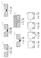
There now follows an explanation as to the
precursor referring to FIGS. 12A to 12E. The figures
are enlarged views of a nozzle portion of the ink-jet
recording head 1. Ink 11 in the pressure generating
chamber 2 is exposed to outside air at a portion 13
of the opening 12 of the nozzle 5 as illustrated in
FIG. 12A. In the portion 13, as shown in FIG. 12B,
moisture is drawn from the ink 11 to form a high
viscosity ink layer 14 near the meniscus. If a
precursor is carried out as shown in FIGS. 12C and 12D,
the meniscus vibration very slightly. With this
vibration, the high viscosity ink layer 14 and low
viscosity ink layer 23 are agitated to uniform the
viscosity of ink in the pressure generating chamber 2
as illustrated in FIG. 12E. In FIG. 12E, reference
numeral 15 denotes ink whose viscosity is uniformed.
In order to perform the precursor, a driving
voltage that is lower than that for ejecting a normal
ink drop has to be applied. Another driving power
supply is required accordingly.
Although the above operation (precursor) is
effective if no ink drop is ejected for a short
period of time, it simply decreases the speed at
which the viscosity of ink increases because the ink
11 in the nozzle 5 is not replaced with a new one.
If, therefore, no ink drop is ejected for a long period
of time, the ink 11 will solidify in the nozzle 5,
which makes it difficult or impossible to eject an ink
drop again.
When the very small vibration changes the meniscus
from a convex to a concave as shown in FIGS. 13B to
13D, ink 11a that increases in viscosity is likely
to attach and remain on the nozzle plate 3 near the
nozzle. The ink remaining on the nozzle plate 3 causes
the ink ejecting direction to be shifted.
For example, Jpn. Pat. Appln. KOKAI Publication
No. 9-29996 described above discloses a method
including a step (precursor) of providing such a small
vibration that no ink drops jump out of the nozzle
even when no ink drops are ejected from the nozzle and
a step of retreating the ink-jet recording head from
a printing area in a fixed period of time and ejecting
the ink 11 from the pressure generating chamber 2 and
from near the opening of the nozzle 5 (hereinafter
referred to as a spit operation). The spit operation
requires its own driving voltage waveform whose
potential difference is greater than that of a driving
voltage waveform used for normal printing, and a large
amount of ink 11 is ejected from the pressure
generating chamber 2 and replaced with a new one,
thereby preventing ink from solidifying and increasing
in viscosity for a long period of time.
The method of the Publication necessitates
a driving waveform exclusively for the spit operation,
and the driving waveform requires three different
waveforms of a normal ejecting waveform, a precursor
driving waveform and a spit driving waveform.
The number of driving power supplies therefore
increases to make a driving circuit complicated and
thus make the ink-jet recording apparatus expensive.
If the ink-jet recording apparatus turns off and
sits idle for a long period of time without performing
any precursor or spit operation, the ink 11 remaining
near the nozzle 5 increases in viscosity and easily
solidifies.
In an ink ejecting operation prior to a printing
operation, too, ink that increases in viscosity is
attached to the periphery of the nozzle 5 of the nozzle
plate 3, as is a coagulation of solidified ink, thereby
shifting the ink ejecting direction.
An object of the present invention is to provide
an ink-jet head driving method and an ink-jet recording
apparatus each capable of preventing ink that increases
in viscosity and a coagulation of solidified ink from
attaching to the periphery of a nozzle.
According to an aspect of the present invention,
there is provided an ink-jet head driving method of
an ink-jet recording apparatus including a pressure
chamber that contains ink, a nozzle communicating with
the pressure chamber, which ejects the ink from the
pressure chamber, an ink-jet head having an actuator
that increases and decreases a capacity of the pressure
chamber, and a driving signal generation unit that
supplies the actuator with a driving signal to eject
an ink drop from the nozzle, the method comprising
supplying the actuator with a very low pressure driving
signal to increase the capacity of the pressure chamber
and then return the increased capacity to an original
size when no ink is ejected from the nozzle, a pulse
width of the very low pressure driving signal being
about twice as long as a pressure propagation time
period during which a pressure wave in the ink
propagates through the pressure chamber.
This summary of the invention does not necessarily
describe all necessary features so that the invention
may also be a sub-combination of these described
features.
The invention can be more fully understood from
the following detailed description when taken in
conjunction with the accompanying drawings, in which:
Embodiments of the present invention will now
be described with reference to the accompanying
drawings. FIG. 1 is a sectional view of the main part
of an ink-jet recording head according to a first
embodiment of the present invention. FIG. 2 is
a sectional view taken along line A-A of FIG. 1.
Referring to FIGS. 1 and 2, an ink jet head 21 is
divided into a plurality of pressure chambers 31 for
containing ink. A partition wall 32 is formed between
adjacent pressure chambers 31. Each of the pressure
chambers 31 has a nozzle 33 for ejecting ink drops.
The nozzle 33 is formed in a nozzle plate 30. A
vibrating plate 34 is formed on the bottom of each of
the pressure chambers 31. A piezoelectric member 35 is
fixed on the underside of the vibrating plate 34. The
vibrating plate 34 and piezoelectric member 35 make up
an actuator.
The ink-jet head 21 includes a common pressure
chamber 36 communicating with each of the pressure
chambers 31. The common pressure chamber 36 is
supplied with ink from ink supply means (not shown)
through an ink supply inlet 37. The pressure chambers
31 and nozzle 33 as well as the common pressure chamber
36 are filled with ink. If the pressure chambers 31
and nozzle 33 are filled with ink, a meniscus is formed
in the nozzle 33.
In FIG. 1, reference numeral 22 indicates driving
signal generation means that supplies a driving signal
to the piezoelectric member 35. The driving signal
generation means 22 receives temperature information
sensed by a temperature sensor 38 that is attached to
the back of the common pressure chamber 36. The means
22 outputs a driving pulse for ink ejection as shown in
FIG. 4 and a driving pulse for a precursor as shown in
FIG. 6. The means 22 also receives image data.
The driving signal generation means 22 includes
a circuit that generates a driving pulse for ink
ejection and a driving pulse for a precursor as a very
low pressure driving signal. This circuit will now
be described with reference to FIG. 3. In FIG. 3,
a series-connection element of p-channel MOSFET Q1 and
n-channel MOSFET Q2 and that of p-channel MOSFET Q3 and
n-channel MOSFET Q4 are connected between a single
driving power supply Vcc and a ground. The gate
potentials of the MOSFETs Q1 to Q4 are controlled
independently of each other. An output signal 1 is
issued from a node between the p-channel and n-channel
MOSFETs Q1 and Q2, and an output signal 2 is issued
from a node between the p-channel and n-channel MOSFETs
Q3 and Q4. The output signal 1 is supplied to one
electrode terminal of the piezoelectric member 35 and
the output signal 2 is connected to the other electrode
terminal thereof.
The MOSFETs Q1 and Q4 turn on for a period of
time Ta and the MOSFETs Q2 and Q3 turn off for a period
of time Ta to generate an expanded pulse p1 shown in
FIG. 4. Then, the MOSFETs Q1 and Q4 turn off for a
period of time 2Ta and the MOSFETs Q2 and Q3 turn on
for a period of time 2Ta to generate a contracted pulse
p2 shown in FIG. 4. These pulses p1 and p2 compose
a driving pulse for ink ejection.
The MOSFETs Q1 and Q4 turn on for a period of time
2Ta and the MOSFETs Q2 and Q3 turn off for a period of
time 2Ta to generate an expanded pulse p1 of -Vcc
shown in FIG. 6. Only the extended pulse p1 composes
a driving pulse for a precursor.
In FIG. 4, Ta indicates a pressure propagation
time period required to propagate a pressure wave
generated in a pressure chamber 31 from one end of
the chamber 31 to the other end thereof.
FIG. 5 shows a relationship between the driving
pulse q for ink ejection shown in FIG. 4, which is
generated from the driving signal generation means 22,
and the oscillation waveform r of pressure generated in
the pressure chambers 31. This relationship will now
be described with reference to FIG. 5.
When a voltage of -Vcc is applied between
electrodes of the piezoelectric member 35 for a period
of time Ta, the member 35 is deformed to increase the
capacity of the pressure chambers 31 and thus the
pressure chambers 31 generate a negative pressure.
This pressure is inverted to a positive pressure
as shown in FIG. 5 after a lapse of the pressure
propagation time Ta. When the pressure propagation
time Ta elapses, a voltage of +Vcc is applied between
the electrodes of the piezoelectric member 35 for
a period of time 2Ta. The member 35 is thus deformed
to decrease the capacity of the pressure chambers 31.
The pressure chambers 31 generate a positive pressure.
The amplitude of a pressure wave generated from the
positive pressure, which is in phase with a pressure
wave generated first, is increased suddenly.
Concurrently with this, the nozzle 33 ejects an ink
drop.
When time 2Ta elapses, the pressure in the
pressure chambers 31 changes from a positive to
a negative and then a positive. If the voltage between
electrodes of the piezoelectric member 35 returns to
zero during the lapse of time 2Ta, the pressure in the
pressure chambers 31 becomes negative and the phase of
the pressure wave is reversed. Accordingly, the
amplitude of the pressure wave decreases and so does
the vibration of the residual pressure.
As described above, the nozzle 33 ejects ink
if the driving signal generation means 22 generates
a driving pulse q for ink ejection as shown in FIG. 4.
FIG. 7 shows a relationship between the driving
pulse q for the precursor and the vibration waveform
r of pressure generated in the pressure chambers 31.
This relationship will now be described with reference
to FIG. 7. FIGS. 8A to 8D illustrate a meniscus of ink
moving in the nozzle 33.
When a voltage of -Vcc is applied between
electrodes of the piezoelectric member 35, the member
35 is deformed to increase the capacity of the pressure
chambers 31. The pressure chambers 31 thus generate
a negative pressure and the meniscus in the nozzle 33
retreats toward the pressure chambers 31 (FIGS. 8A and
8B). After a lapse of time 2Ta that is about twice as
long as the pressure propagation time Ta, the pressure
in the pressure chambers 31 changes from a negative to
a positive and then a negative. If the voltage applied
between the electrodes of the piezoelectric member 35
returns to zero when time 2Ta elapses or when the
pressure in the pressure chambers 31 is negative, the
increased capacity of the pressure chambers 31 returns
to its original size and thus the pressure in the
chambers 31 becomes positive. Since, therefore, the
phase of the pressure wave is reversed when the voltage
returns to zero, the amplitude of the pressure wave
decreases and so does the oscillation of the residual
pressure.
As described above, the capacity of the pressure
chambers 31 increases and returns to its original size
such that the meniscus does not change to a convex on
the surface of the nozzle plate 30 by the driving pulse
q for the precursor. The time required for returning
the capacity is set twice as long as the pressure
propagation time Ta. Therefore, the capacity of the
pressure chambers 31, which increases when the pressure
in the chambers 31 is negative, returns to its original
size. The pressure vibration is attenuated and the
convex of the meniscus of reacting ink is minimized
as illustrated in FIG. 8C. After that, the meniscus
returns to a position in the nozzle 33 as shown in
FIG. 8D.
With the above operation, the driving pulse q for
the precursor can prevent ink from attaching and
remaining on the surface of the nozzle plate 30 near
the nozzle 33. The ejecting direction of ink drops can
thus be prevented from shifting to thereby achieve
stable, high-quality printing.
The driving pulse for a precursor and that for
ink ejection are generated by the same driving power
supply Vcc. The costs for the ink-jet recording
head apparatus can thus be lowered with a simple
configuration of the driving circuit.
The driving period Tc of a driving pulse for
a precursor shown in FIG. 9A is about ten times as long
as the driving period Tb of a driving pulse for ink
ejection shown in FIG. 9B.
If Tc is considerably longer than Tb, the ink-jet
recording apparatus can decrease in power consumption
when it stands by for printing.
Even though a driving pulse for a precursor is
applied between electrodes of the piezoelectric member
35 a given number of times, ink in the nozzle 33 is
likely to increase in viscosity when nonprinting time
is longer than a certain period of time.
In the above case, a spit operation is periodically
performed to discharge the ink that increases in
viscosity in a nonprinting area. The driving circuit
shown in FIG. 3 can generate a driving pulse in the
spit operation. The driving waveform of the driving
pulse is the same as that shown in FIG. 4, as is the
driving voltage Vcc thereof.
As described above, the spit operation is
performed when nonprinting time is longer than a
certain period of time. It is thus possible to prevent
ink from attaching and remaining on the surface of the
nozzle plate near the nozzle. Consequently, it is
possible to prevent the ejecting direction of ink drops
from shifting, thereby achieving stable, high-quality
printing.
The driving power supply of a driving pulse in the
spit operation is the same as the power supply Vcc of
both the driving pulse for a precursor and that for
ink ejection. The arrangement of the driving circuit
can be simplified to lower the costs for the ink-jet
recording apparatus.
When the apparatus turns off and sits idle for a
long period of time, ink in the nozzle 33 considerably
increases in viscosity or solidifies. No advantages
can thus be obtained even using the same driving pulse
as those for the precursor and spit operations
described above.
In order to resolve the above problem, an ink-jet
recording apparatus according to a second embodiment
of the present invention will now be described with
reference to FIG. 10. Referring to FIG. 10, a tube 42
is connected to a common ink chamber 36 through an ink
supply inlet 37 and a filter 41. The tube 42 is
provided with an ink filling pump 43 that allows ink
to flow in forward and backward directions. The inlet
of the pump 43 is connected to an ink bottle 44.
A driving unit 45 controls the pump 43 to allow ink to
flow forward and backward.
Assume that the ink-jet recording apparatus with
the above configuration turns off and sits idle for
a long period of time and ink in the nozzle 33
considerably increases in viscosity or solidifies.
First, the pump 43 is driven in the backward direction
to cause ink to flow from the nozzle 33 in the
direction of arrow a through the tube 42. The ink is
agitated in a pressure chamber 31. Then, the pump 43
is driven in the forward direction to discharge ink
from the pressure chamber 31 through the nozzle 33 and
supply a new ink into the pressure chamber 31 from the
pressure chamber 31 in the ink bottle 44.
The above operation makes it possible to prevent
ink that increases in viscosity and a coagulation
of solidified ink from attaching and remaining on
the surface of the nozzle plate near the nozzle.
Consequently, the ejecting direction of ink drops can
be prevented from shifting to thereby achieve stable,
high-quality printing.
When the pump 43 causes ink to flow backward from
the nozzle 33 to the pressure chamber 31 and agitate it
therein, a cap can be put on the nozzle plate to apply
a positive pressure.
A driving pulse for a precursor can be generated
from the driving signal generation means 22 to return
ink to the pressure chamber 31 from the nozzle 33 and
agitate the ink while slightly oscillating the pressure
chamber 31.
In the above embodiments, the driving period Tc of
a driving pulse for a precursor is about ten times as
long as the driving period Tb of a driving pulse for
ink ejection. However, the embodiments are not limited
to this.