EP1498353A1 - Packaging machine - Google Patents
Packaging machine Download PDFInfo
- Publication number
- EP1498353A1 EP1498353A1 EP04012907A EP04012907A EP1498353A1 EP 1498353 A1 EP1498353 A1 EP 1498353A1 EP 04012907 A EP04012907 A EP 04012907A EP 04012907 A EP04012907 A EP 04012907A EP 1498353 A1 EP1498353 A1 EP 1498353A1
- Authority
- EP
- European Patent Office
- Prior art keywords
- packaging machine
- drive
- transport
- machine according
- engagement
- Prior art date
- Legal status (The legal status is an assumption and is not a legal conclusion. Google has not performed a legal analysis and makes no representation as to the accuracy of the status listed.)
- Granted
Links
Images


Classifications
-
- B—PERFORMING OPERATIONS; TRANSPORTING
- B65—CONVEYING; PACKING; STORING; HANDLING THIN OR FILAMENTARY MATERIAL
- B65B—MACHINES, APPARATUS OR DEVICES FOR, OR METHODS OF, PACKAGING ARTICLES OR MATERIALS; UNPACKING
- B65B41/00—Supplying or feeding container-forming sheets or wrapping material
- B65B41/12—Feeding webs from rolls
- B65B41/14—Feeding webs from rolls by grippers
-
- B—PERFORMING OPERATIONS; TRANSPORTING
- B31—MAKING ARTICLES OF PAPER, CARDBOARD OR MATERIAL WORKED IN A MANNER ANALOGOUS TO PAPER; WORKING PAPER, CARDBOARD OR MATERIAL WORKED IN A MANNER ANALOGOUS TO PAPER
- B31B—MAKING CONTAINERS OF PAPER, CARDBOARD OR MATERIAL WORKED IN A MANNER ANALOGOUS TO PAPER
- B31B70/00—Making flexible containers, e.g. envelopes or bags
- B31B70/02—Feeding or positioning sheets, blanks or webs
- B31B70/10—Feeding or positioning webs
Definitions
- the present invention relates to a packaging machine according to the preamble of claim 1.
- Such a packaging machine is for example from the DE 2 123 133 known. It has a frame, the two parallel Frame parts arranged in the longitudinal direction relative to one another having. At one end of the two frame parts are respectively Sprockets provided over the two transport chains in shape run by endless chains.
- the individual links of the Transport chains are equipped with brackets which are a packaging material web how to hold a foil by the edges. When the chain links engage the sprockets, open the brackets, so that the packaging material web is inserted into the parentheses. If the chain links get rid of the sprockets, the brackets close and the packaging material web is between the transport chains held in a stretched state.
- the sprockets are each stored on an axis flying.
- a film guide drum for the packaging material web freely rotatably mounted about an axis.
- further sprockets are provided, which serve by intervening in the transport chains to open the clips again so that the packaging material web released from the brackets.
- Workstations arranged. In the transport of Packaging material web through the workstations is one high accuracy of feeds of both chains required to in successive operations as low as possible feed tolerances to reach. Higher tolerances require more Packaging material and cause additional costs.
- the transport chains However, they have a limited strength and are stretched elastically under load like a spring.
- FIG. 5 There are at the inlet the transport path shown three lines a-a, b-b and c-c. each the lines interpose an imaginary connecting line two mutually corresponding chain links.
- the line a-a represents the ideal state in which the imaginary Connecting line runs parallel to the axis 14 at the outlet, i.e. There is no offset on the transport route the two transport chains 5 and 6.
- the lines b-b and c-c show the possible range of variation of the distortion of the material web 7.
- the line b-b shows the case where the chain 5 opposite the chain 6 in the transporting direction A, while the line c-c shows the case where the chain 5 faces the chain 6 lags.
- first engagement element with the second engagement element is coupled so that both engagement elements are synchronized with each other in an angle
- Enema on the entry side make sure that the transport routes the two means of transport are the same length. Possible Tolerances due to uneven stretching of the means of transport due to high tensile loads can be compensated become. Consequently, the packaging machine can with greater length than previously designed without undue Large tolerances in the transport routes of the two means of transport to obtain.
- the transport device is in two places driven by two drive devices, thereby initiating the load on the means of transport at several Points can be made so that it reduces per discharge point is.
- the advantage is achieved that it thereby it is possible to use smaller drive devices.
- the drive devices are advantageously controlled by a control device, so that they are synchronized with each other. Thereby can realize an angle-synchronous rotation of the drive shafts are, i. it will become so-called electronic Realized waves, where a wave acts as a "master”, and the other as a “slave”, depending on the master wave is controlled.
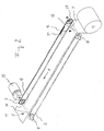
- a packaging machine according to FIG A first embodiment, a frame 1, the two parallel to each other in the longitudinal direction arranged frame parts contains, of which only the frame part 1a in Fig. 1 to see is.
- the packaging machine transports a packaging material web 7 from an inlet 16 at an inlet side to a spout 17 on an exit side in the transport direction A.
- the frame parts are made of pairs of support legs 18, 19 and 20 worn.
- Workstations 2, 3 and 4 arranged at which the packaging material web is processed.
- the transport of the packaging material web 7 happens via transport chains 5 and 6 in Shape of endless chains.
- the first frame part is at the outlet 17 a first sprocket 8 and the inlet 16 a first engagement element 10, which also designed as a sprocket is assigned.
- the two transport chains 5 and 6 each run over the two sprockets 8, 9 at the outlet and via the two engagement elements 10, 11 at the inlet 16.
- Each transport chain 5, 6 consists of a plurality of chain links, only a few of which are indicated in FIG. 2 by the reference numeral 21 are shown schematically.
- the individual chain links 21 are equipped with brackets, not shown here, the packaging material web 7, e.g. a plastic film, hold at their longitudinal edges. If the chain links 21 with the engagement elements 10, 11 at the inlet 16 into engagement enter, open the brackets, so that the packaging material web 7 can enter the brackets. If the Chain links 21 are released from the engagement elements 10, 11, close the brackets and the packaging material web is held between the transport chains in a stretched state. Conversely, the brackets open at the sprockets 8 and 9 at the outlet 17. This is the packaging material web 7 of the brackets again and can over the outlet 17 leave the packaging machine while the transport chains 5, 6 are deflected over the sprockets by 180 ° and again running back.
- the sprockets 8, 9 are on a common drive shaft 14 rotatably mounted.
- the drive shaft 14 is provided with a drive device 15 coupled in the form of an electric motor.
- the shaft is dimensioned so that it is as torsionally stiff as possible is, i. that the drive shaft when driving the Transport chains 5, 6 is not twisted as possible to prevent that the further away from the drive device 14 arranged and driven by the sprocket 8 transport chain 5 with respect to the closer to the drive device 14th arranged and driven by the sprocket 9 transport chain 6 lags.
- the drive device 14 rotates the sprockets 8, 9 in the counterclockwise direction in Fig. 2, so that the Packaging material web 7 transported in the transport direction A. becomes.
- the transport chains have a limited strength, they are stretched elastically under load like a spring, especially for longer systems from about 10m transport length occurs. To prevent this, those are at the inlet 16 provided engagement elements 10, 11 in the form of other sprockets via a torsionally rigid shaft 12 rotatably with each other connected, so that the two engagement elements 10 and 11th inevitably run in sync with each other.
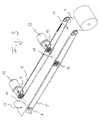
- FIG. 3 an alternative embodiment is shown.
- the structure of the packaging machine shown there is in principle equal to that of the packaging machine shown in Figs. 1 and 2, so that on a description of the matching Components omitted, or on the previous Description is referenced.
- the alternative embodiment differs from the Construction of Fig. 1, characterized in that at the inlet as in the conventional packaging machines free on axles (not shown) mounted sprockets are provided. additionally but is between the inlet and the outlet another torsionally rigid shaft 12 is provided, on which the two engagement elements 10, 11 rotatably secured in the form of sprockets are.
- the shaft 12 with another drive device 13 coupled in the form of an electric motor.
- the two drive devices 13 and 15 are about synchronizes a control, not shown, so that they turn angular synchronously with the same speed.
- the packaging machine can be designed longer, where the driven shaft 12 at a distance of about 10m from the first driven shaft 14 is arranged, since, as already mentioned above, the tolerance of the transport routes of the two Transport chains due to their elastic elongation an increased load from about 10m would be unduly large.
- Fig. 4 is another alternative embodiment shown.
- the structure of the packaging machine shown there is in principle equal to that of the packaging machine shown in FIGS. 1 and 2, so that on a description of the matching Components omitted, or on the previous description is referenced.
- the alternative embodiment differs from the Construction of Fig. 1, characterized in that at the inlet 16 as in the conventional packaging machines free on axles (not shown) mounted sprockets 30, 31 are provided. additionally is however at the level of the inlet below the sprockets 30, 31, the torsionally rigid shaft 12 is provided on the the two engagement elements 10, 11 are rotationally fixed.
- the transport chains 5, 6 are on the below the Packaging material web 7 arranged return side via pulleys 22, 23 about 90 ° from the horizontal down deflected in the vertical in Fig. 4, run over the engagement elements 10, 11, again rising 180 ° be deflected so that they are the packaging material web 7 approach again, and eventually over the sprockets 30, 31 again deflected by approximately 90 ° in the horizontal.
- the torsion-resistant shaft 14 is at the outlet 17 arranged offset downwards, with the transport chains 5, 6 via sprockets 28, 29 and reversing rollers 26, 27 accordingly be redirected.
- the drive device 15 unlike the first embodiment not directly coupled to the shaft 14. Rather, on the shaft 14 a another gear 32 rotatably attached, with a toothed belt 24 is engaged.
- the timing belt 24 is also with a drive pinion 25 in engagement, which via a not shown Drive shaft coupled to the drive device 15 is.
- the drive device is arranged so that they located directly below the shaft 14. This allows the drive device space-saving housed within the frame 1 become and laterally in the width direction not outside.
- each of the sprockets 8 to 11 via its own drive device drive and each drive device over to synchronize a control angle synchronously.
- a further advantageous embodiment of the invention provides to use a toothed belt instead of the transport chain.
Abstract
Description
Die vorliegende Erfindung betrifft eine Verpackungsmaschine nach dem Oberbegriff des Patentanspruchs 1.The present invention relates to a packaging machine according to the preamble of claim 1.
Eine derartige Verpackungsmaschine ist beispielsweise aus der DE 2 123 133 bekannt. Sie besitzt einen Rahmen, der zwei parallel zueinander in Längsrichtung angeordnete Rahmenteile aufweist. An einem Ende der beiden Rahmenteile sind jeweils Kettenräder vorgesehen, über die zwei Transportketten in Form von Endlosketten laufen. Die einzelnen Kettenglieder der Transportketten sind mit Klammern ausgestattet, die eine Verpackungsmaterialbahn wie eine Folie an den Rändern halten. Wenn die Kettenglieder mit den Kettenrädern in Eingriff gelangen, öffnen sich die Klammern, so daß die Verpackungsmaterialbahn in die Klammern eingeführt wird. Wenn die Kettenglieder von den Kettenrädern freikommen, schließen sich die Klammern und die Verpackungsmaterialbahn wird zwischen den Transportketten in gespanntem Zustand gehalten. Die Kettenräder sind jeweils auf einer Achse fliegend gelagert. Zwischen den Kettenrädern ist eine Folienführungstrommel für die Verpackungsmaterialbahn um eine Achse frei drehbar gelagert. Am anderen Ende der beiden Rahmenteile sind weitere Kettenräder vorgesehen, die dazu dienen, durch Eingreifen in die Transportketten die Klammern wieder zu öffnen, so daß die Verpackungsmaterialbahn von den Klammern freikommt. Entlang des Rahmens sind verschiedene Arbeitsstationen angeordnet. Bei dem Transport der Verpackungsmaterialbahn durch die Arbeitsstationen ist eine hohe Genauigkeit der Vorschübe beider Ketten erforderlich, um bei aufeinanderfolgenden Arbeitsgängen möglichst geringe Vorschubtoleranzen zu erreichen. Höhere Toleranzen erfordern mehr Verpackungsmaterial und verursachen Mehrkosten. Die Transportketten weisen jedoch eine begrenzten Festigkeit auf und werden bei Belastung wie eine Feder elastisch gedehnt. Besonders bei längeren Anlagen ab ca. 10m Transportlänge wirkt sich diese Dehneigenschaft merklich auf die Genauigkeit der Transportsstrecke aus, da die Belastung aufgrund der Länge zunimmt und eine höhere Antriebskraft eine noch größere Dehnung zur Folge hat. Gleichzeitig ergibt die relative Dehnung bei größerer Anlagenlänge höhere Dehnbeträge, die praktisch überproportional höhere Toleranzen verursachen. Zusätzlich können die Schwankungen an den beiden Transportketten unterschiedlich ausfallen und damit Verzerrungen der Verpackungsbahn verursachen, die je nach Art des Verpackungsmaterials sogar zu einem Zerreißen der Materialbahn führen können.Such a packaging machine is for example from the DE 2 123 133 known. It has a frame, the two parallel Frame parts arranged in the longitudinal direction relative to one another having. At one end of the two frame parts are respectively Sprockets provided over the two transport chains in shape run by endless chains. The individual links of the Transport chains are equipped with brackets which are a packaging material web how to hold a foil by the edges. When the chain links engage the sprockets, open the brackets, so that the packaging material web is inserted into the parentheses. If the chain links get rid of the sprockets, the brackets close and the packaging material web is between the transport chains held in a stretched state. The sprockets are each stored on an axis flying. Between the sprockets is a film guide drum for the packaging material web freely rotatably mounted about an axis. At the other At the end of the two frame parts, further sprockets are provided, which serve by intervening in the transport chains to open the clips again so that the packaging material web released from the brackets. Along the frame are different Workstations arranged. In the transport of Packaging material web through the workstations is one high accuracy of feeds of both chains required to in successive operations as low as possible feed tolerances to reach. Higher tolerances require more Packaging material and cause additional costs. The transport chains However, they have a limited strength and are stretched elastically under load like a spring. Especially at longer systems from about 10m transport length, this affects Dehneigenschaft noticeable on the accuracy of the transport route because the load increases due to the length and a higher driving force results in even greater elongation Has. At the same time, the relative elongation results with a larger system length higher strains, which are practically disproportionate cause higher tolerances. In addition, the fluctuations can be different on the two transport chains and thus cause distortion of the packaging web ever after the type of packaging material even to a rupture of Can lead material web.
Als Beispiel sei auf Fig. 5 verwiesen. Dort sind am Einlauf
der Transportbahn drei Linien a-a, b-b und c-c gezeigt. Jede
der Linien stellt eine imaginäre Verbindungslinie zwischen
zwei zueinander korrespondierenden Kettengliedern dar. Die Linie
a-a stellt dabei den Idealzustand dar, bei dem die imaginäre
Verbindungslinie parallel zur Achse 14 am Auslauf verläuft,
d.h. es tritt keinerlei Versatz auf dem Transportweg
der beiden Transportketten 5 und 6 auf. Die Linien b-b und c-c
zeigen den möglichen Schwankungsbereich der Verzerrung der Materialbahn
7. Die Linie b-b zeigt den Fall, bei dem die Kette
5 gegenüber der Kette 6 in der Transportrichtung A voreilt,
während die Linie c-c den Fall zeigt, bei dem die Kette 5 gegenüber
der Kette 6 nacheilt. In Versuchen wurde festgestellt,
daß bei einer Anlagenlänge von 10m und einer Belastung von
3000N eine elastische Längung der Transportkette von 15mm auftreten
kann. Ein Versatz von 15mm kann u.U. ausreichen, daß
die Verpackungsmaterialbahn zerreißt oder daß die Arbeitsstation
die Bahn nicht an der korrekten Position bearbeitet. Eine
Anlage, die länger als 10m ist, ist daher zumindest nach herkömmlichen
Methoden nicht realisierbar.As an example, reference is made to FIG. 5. There are at the inlet
the transport path shown three lines a-a, b-b and c-c. each
the lines interpose an imaginary connecting line
two mutually corresponding chain links. The line
a-a represents the ideal state in which the imaginary
Connecting line runs parallel to the
Es ist daher Aufgabe der vorliegenden Erfindung, eine Verpackungsmaschine zu schaffen, mit der die Toleranzen der Transportstrecken minimiert werden können.It is therefore an object of the present invention, a packaging machine to create, with the tolerances of the transport routes can be minimized.
Diese Aufgabe wird mit einer Verpackungsmaschine gemäß Anspruch 1 gelöst.This object is achieved with a packaging machine according to claim 1 solved.
Vorteilhafte Weiterbildungen und besondere Ausführungsformen der Verpackungsmaschine sind Gegenstand der Unteransprüche.Advantageous developments and special embodiments the packaging machine are the subject of the dependent claims.
Dadurch, daß das erste Eingriffselement mit dem zweiten Eingriffselement so gekoppelt ist, daß beide Eingriffselemente winkelsynchron miteinander abgestimmt sind, läßt sich auch am Einlauf auf der Eingangsseite sicherstellen, daß die Transportstrecken der beiden Transportmittel gleich lang sind. Mögliche Toleranzen durch eine ungleichmäßige Dehnung der Transportmittel aufgrund hoher Zugbelastungen können dadurch kompensiert werden. Folglich kann die Verpackungsmaschine mit größerer Länge als bisher ausgelegt werden, ohne unzulässig große Toleranzen in den Transportstrecken der beiden Transportmittel zu erhalten.In that the first engagement element with the second engagement element is coupled so that both engagement elements are synchronized with each other in an angle, can also be on Enema on the entry side make sure that the transport routes the two means of transport are the same length. Possible Tolerances due to uneven stretching of the means of transport due to high tensile loads can be compensated become. Consequently, the packaging machine can with greater length than previously designed without undue Large tolerances in the transport routes of the two means of transport to obtain.
Es ist vorteilhaft, eine torsionssteife Welle vorzusehen, auf der die beiden Eingriffselemente drehfest angeordnet sind, da dies eine einfache und kostengünstige Lösung des der Erfindung zugrunde liegenden Problems ermöglicht. Zudem ist es dadurch möglich, auch Altanlagen ohne großen konstruktiven Aufwand nachzurüsten, indem die beiden bereits vorhandenen auf Achsen drehbar gelagerten Eingriffselemente nachträglich auf die Welle drehfest montiert werden. It is advantageous to provide a torsionally rigid shaft on the two engagement elements are arranged rotationally fixed, there this is a simple and inexpensive solution of the invention underlying problem. It is also because of that possible, even old systems without great design effort Retrofit by the two already existing on axes rotatably mounted engagement elements subsequently on the shaft rotatably mounted.
Es ist vorteilhaft, eine Antriebsvorrichtung vorzusehen, die das erste und das zweite Eingriffselement gemeinsamen antreibt. Dadurch wird die Transporteinrichtung an zwei Stellen durch zwei Antriebsvorrichtungen angetrieben, wodurch die Einleitung der Belastung auf die Transportmittel an mehreren Punkten erfolgen kann, so daß sie pro Einleitungspunkt reduziert ist. Außerdem wird der Vorteil erzielt, daß es dadurch möglich ist, kleinere Antriebsvorrichtungen einzusetzen.It is advantageous to provide a drive device which the first and the second engagement member common drives. As a result, the transport device is in two places driven by two drive devices, thereby initiating the load on the means of transport at several Points can be made so that it reduces per discharge point is. In addition, the advantage is achieved that it thereby it is possible to use smaller drive devices.
Es ist ferner vorteilhaft, je eine Antriebsvorrichtung jeweils für das erste und das zweite Eingriffselement vorzusehen und synchron anzutreiben. Dadurch ist es möglich, noch kleinere Antriebsvorrichtungen einzusetzen. Die Antriebsvorrichtungen werden in vorteilhafter Weise durch eine Steuervorrichtung gesteuert, so daß sie miteinander synchronisiert sind. Dadurch kann eine winkelsynchrone Drehung der Antriebswellen realisiert werden, d.h. es werden dadurch sogenannte elektronische Wellen realisiert, wobei eine Welle als "Master" fungiert, und die andere als "Slave", indem sie in Abhängigkeit von der Master-Welle angesteuert wird.It is also advantageous, depending on a drive device to provide for the first and the second engagement element and to drive synchronously. This makes it possible, even smaller Use drive devices. The drive devices are advantageously controlled by a control device, so that they are synchronized with each other. Thereby can realize an angle-synchronous rotation of the drive shafts are, i. it will become so-called electronic Realized waves, where a wave acts as a "master", and the other as a "slave", depending on the master wave is controlled.
Nachfolgend wird die Erfindung anhand mehrerer bevorzugter
Ausführungsbeispiele unter Bezugnahme auf die beigefügten Figuren
näher erläutert.
Unter Bezugnahme auf Fig. 1 weist eine Verpackungsmaschine gemäß
einem ersten Ausführungsbeispiel einen Rahmen 1 auf, der
zwei parallel zueinander in Längsrichtung angeordnete Rahmenteile
enthält, von denen nur der Rahmenteil 1a in Fig. 1 zu
sehen ist. Die Verpackungsmaschine transportiert eine Verpackungsmaterialbahn
7 von einem Einlauf 16 an einer Eingangsseite
zu einem Auslauf 17 an einer Ausgangsseite in der Transportrichtung
A. Die Rahmenteile werden von Paaren von Stützbeinen
18, 19 und 20 getragen. Entlang der Rahmenteile 1a sind
Arbeitsstationen 2, 3 und 4 angeordnet, an denen die Verpackungsmaterialbahn
verarbeitet wird. Der Transport der Verpackungsmaterialbahn
7 geschieht über Transportketten 5 und 6 in
Form von Endlosketten.Referring to FIG. 1, a packaging machine according to FIG
A first embodiment, a frame 1, the
two parallel to each other in the longitudinal direction arranged frame parts
contains, of which only the frame part 1a in Fig. 1 to
see is. The packaging machine transports a
In Fig. 2 und allen weiteren Figuren 3 bis 5 wurde zur Vereinfachung
der Lesbarkeit der Figuren auf die Darstellung der
Rahmenteile verzichtet. Gemäß Fig 2 ist dem ersten Rahmenteil
am Auslauf 17 ein erstes Kettenrad 8 und am Einlauf 16 ein
erstes Eingriffselement 10, das ebenfalls als Kettenrad ausgebildet
ist, zugeordnet. Entsprechend ist dem zweiten Rahmenteil
am Auslauf 17 ein zweites Kettenrad 9 und am Einlauf 16
ein zweites Eingriffselement 11, das ebenfalls als Kettenrad
ausgebildet ist, zugeordnet. Die zwei Transportketten 5 und 6
laufen jeweils über die beiden Kettenräder 8, 9 am Auslauf und
über die beiden Eingriffselemente 10, 11 am Einlauf 16.In Fig. 2 and all other figures 3 to 5 was for simplicity
the readability of the figures on the representation of the
Frame parts omitted. According to FIG. 2, the first frame part is
at the outlet 17 a
Jede Transportkette 5, 6 besteht aus einer Vielzahl von Kettengliedern,
von denen nur einige in Fig. 2 unter dem Bezugszeichen
21 schematisch dargestellt sind. Die einzelnen Kettenglieder
21 sind mit hier nicht dargestellten Klammern ausgestattet,
die die Verpackungsmaterialbahn 7, z.B. eine Kunststofffolie,
an ihren Längsrändern halten. Wenn die Kettenglieder
21 mit den Eingriffselementen 10, 11 am Einlauf 16 in Eingriff
gelangen, öffnen sich die Klammern, so daß die Verpackungsmaterialbahn
7 in die Klammern einlaufen kann. Wenn die
Kettenglieder 21 von den Eingriffselementen 10, 11 freikommen,
schließen sich die Klammern und die Verpackungsmaterialbahn
wird zwischen den Transportketten in gespanntem Zustand gehalten.
Umgekehrt öffnen sich die Klammern bei den Kettenrädern 8
und 9 am Auslauf 17. Dadurch kommt die Verpackungsmaterialbahn
7 von den Klammern wieder frei und kann über den Auslauf 17
die Verpackungsmaschine verlassen, während die Transportketten
5, 6 über die Kettenräder um 180° umgelenkt werden und wieder
zurücklaufen.Each
Die Kettenräder 8, 9 sind auf einer gemeinsamen Antriebswelle
14 drehfest gelagert. Die Antriebswelle 14 ist mit einer Antriebsvorrichtung
15 in Form eines Elektromotors gekoppelt.
Die Welle ist so dimensioniert, daß sie möglichst torsionssteif
ist, d.h. daß die Antriebswelle beim Antreiben der
Transportketten 5, 6 möglichst nicht tordiert wird, um zu verhindern,
daß die von der Antriebsvorrichtung 14 weiter entfernt
angeordnete und über das Kettenrad 8 angetriebene Transportkette
5 gegenüber der näher an der Antriebsvorrichtung 14
angeordneten und über das Kettenrad 9 angetriebenen Transportkette
6 nacheilt. Die Antriebsvorrichtung 14 dreht die Kettenräder
8, 9 entgegen dem Uhrzeigersinn in Fig. 2, so daß die
Verpackungsmaterialbahn 7 in der Transportrichtung A transportiert
wird.The
Da die Transportketten jedoch eine begrenzten Festigkeit besitzen,
werden sie bei Belastung wie eine Feder elastisch gedehnt,
was besonders bei längeren Anlagen ab ca. 10m Transportlänge
auftritt. Um dies zu verhindern, sind die am Einlauf
16 vorgesehenen Eingriffselemente 10, 11 in Form weiterer Kettenräder
über eine torsionssteife Welle 12 drehfest miteinander
verbunden, so daß die beiden Eingriffselemente 10 und 11
zwangsläufig synchron zueinander laufen.However, since the transport chains have a limited strength,
they are stretched elastically under load like a spring,
especially for longer systems from about 10m transport length
occurs. To prevent this, those are at the
Im Betrieb führt die drehsteife Verbindung zwischen den Eingriffselementen
10, 11 dazu, daß die Kettenglieder der einen
Transportkette gezwungen werden, winkelsynchron zu den Kettengliedern
der zweiten Transportkette zu laufen.In operation, the torsionally rigid connection between the
In Fig. 3 ist ein alternatives Ausführungsbeispiel gezeigt. Der Aufbau der dort gezeigten Verpackungsmaschine ist prinzipiell gleich dem der in den Fig. 1 und 2 gezeigten Verpackungsmaschine, so daß auf eine Beschreibung der übereinstimmenden Bauteile verzichtet, bzw. auf die vorhergehende Beschreibung verwiesen wird.In Fig. 3 an alternative embodiment is shown. The structure of the packaging machine shown there is in principle equal to that of the packaging machine shown in Figs. 1 and 2, so that on a description of the matching Components omitted, or on the previous Description is referenced.
Das alternative Ausführungsbeispiel unterscheidet sich von der
Konstruktion aus Fig. 1 dadurch, daß am Einlauf wie bei den
herkömmlichen Verpackungsmaschinen frei auf Achsen (nicht dargestellt)
gelagerte Kettenräder vorgesehen sind. Zusätzlich
ist jedoch zwischen dem Einlauf und dem Auslauf eine weitere
torsionssteife Welle 12 vorgesehen, auf der die beiden Eingriffselemente
10, 11 in Form von Kettenrädern drehfest befestigt
sind. Außerdem ist die Welle 12 mit einer weiteren Antriebsvorrichtung
13 in Form eines Elektromotors gekoppelt.
Die beiden Antriebsvorrichtungen 13 und 15 werden dabei über
eine nicht dargestellte Steuerung synchronisiert, so daß sie
sich mit der gleichen Drehzahl winkelsynchron drehen. Die Verpackungsmaschine
kann dadurch länger ausgelegt werden, wobei
die angetriebene Welle 12 in einem Abstand von ca. 10m von der
ersten angetriebenen Welle 14 angeordnet ist, da, wie bereits
eingangs erwähnt, die Toleranz der Transportstrecken der beiden
Transportketten aufgrund ihrer elastischen Dehnung durch
eine erhöhte Belastung ab ca. 10m unzulässig groß werden würde.The alternative embodiment differs from the
Construction of Fig. 1, characterized in that at the inlet as in the
conventional packaging machines free on axles (not shown)
mounted sprockets are provided. additionally
but is between the inlet and the outlet another
torsionally
In Fig. 4 ist ein weiteres alternatives Ausführungsbeispiel gezeigt. Der Aufbau der dort gezeigten Verpackungsmaschine ist prinzipiell gleich dem der in den Fig. 1 und 2 gezeigten Verpackungsmaschine, so daß auf eine Beschreibung der übereinstimmenden Bauteile verzichtet, bzw. auf die vorhergehende Beschreibung verwiesen wird.In Fig. 4 is another alternative embodiment shown. The structure of the packaging machine shown there is in principle equal to that of the packaging machine shown in FIGS. 1 and 2, so that on a description of the matching Components omitted, or on the previous description is referenced.
Das alternative Ausführungsbeispiel unterscheidet sich von der
Konstruktion aus Fig. 1 dadurch, daß am Einlauf 16 wie bei den
herkömmlichen Verpackungsmaschinen frei auf Achsen (nicht dargestellt)
gelagerte Kettenräder 30, 31 vorgesehen sind. Zusätzlich
ist jedoch in Höhe des Einlaufs unterhalb der Kettenräder
30, 31 die torsionssteife Welle 12 vorgesehen, auf der
die beiden Eingriffselemente 10, 11 drehfest befestigt sind.
Die Transportketten 5, 6 werden dazu auf der unterhalb der
Verpackungsmaterialbahn 7 angeordneten Rücklaufseite über Umlenkrollen
22, 23 um ca. 90° aus der Horizontalen nach unten
in die Vertikale in Fig. 4 umgelenkt, laufen über die Eingriffselemente
10, 11, wobei sie dabei wieder um 180° nach oben
umgelenkt werden, so daß sie sich der Verpackungsmaterialbahn
7 wieder nähern, und werden schließlich über die Kettenräder
30, 31 wieder um ca. 90° in die Horizontale umgelenkt.The alternative embodiment differs from the
Construction of Fig. 1, characterized in that at the
In gleicher Weise ist die torsionssteife Welle 14 am Auslauf
17 nach unten versetzt angeordnet, wobei die Transportketten
5, 6 über Kettenräder 28, 29 und Umlekrollen 26, 27 entsprechend
umgelenkt werden. Zusätzlich ist die Antriebsvorrichtung
15 im Unterschied zum ersten Ausführungsbeispiel nicht direkt
an der Welle 14 angekoppelt. Vielmehr ist an der Welle 14 ein
weiteres Zahnrad 32 drehfest befestigt, das mit einem Zahnriemen
24 in Eingriff steht. Der Zahnriemen 24 ist außerdem mit
einem Antriebsritzel 25 in Eingriff, das über eine nicht gezeigte
Antriebswelle mit der Antriebsvorrichtung 15 gekoppelt
ist. Die Antriebsvorrichtung ist so angeordnet, daß sie sich
direkt unterhalb der Welle 14 befindet. Dadurch kann die Antriebsvorrichtung
platzsparend innerhalb des Rahmens 1 untergebracht
werden und steht in der Breitenrichtung seitlich nach
außen nicht vor.In the same way, the torsion-
Die gleiche Anordnung ist auch für die Antriebsvorrichtung 13
der Welle 12 möglich.The same arrangement is also for the
Außerdem ist es gemäß einer nicht dargestellten Abwandlung
möglich, jedes der Kettenräder 8 bis 11 über eine eigene Antriebsvorrichtung
anzutreiben und jede Antriebsvorrichtung über
eine Steuerung winkelsynchron abzustimmen.In addition, it is according to a modification, not shown
possible, each of the
Eine weitere vorteilhafte Ausgestaltung der Erfindung sieht vor, anstelle der Transportkette einen Zahnriemen zu verwenden.A further advantageous embodiment of the invention provides to use a toothed belt instead of the transport chain.
Claims (11)
einem Rahmen (1) mit zwei einander gegenüberliegenden seitlichen Rahmenteilen (1a, 1b), und
mit einer Transporteinrichtung zum Ergreifen und Transportieren einer Materialbahn (7) von einer Eingangsseite zu einer Ausgangsseite, und
mit einem Antrieb zum Bewegen der Transporteinrichtung, wobei
die Transporteinrichtung ein erstes und ein zweites von der Eingangsseite zur Ausgangsseite verlaufendes Transportmittel (5, 6) aufweist,
dadurch gekennzeichnet, daß
in Bewegungsrichtung der Transportmittel (5, 6) gesehen nach dem Antrieb wenigstens ein in das erste Transportmittel (5) eingreifendes erstes Eingriffselement (10) und ein in das zweite Transportmittel (6) eingreifendes zweites Eingriffselement (11) vorgesehen ist, wobei das erste Eingriffselement (10) mit dem zweiten Eingriffselement (11) derart gekoppelt ist, daß beide Eingriffselemente synchronisiert sind.Packaging machine with
a frame (1) with two opposite lateral frame parts (1a, 1b), and
with a transport device for gripping and transporting a material web (7) from an input side to an output side, and
with a drive for moving the transport device, wherein
the transport device has a first and a second transport means (5, 6) extending from the input side to the exit side,
characterized in that
in the direction of movement of the transport means (5, 6) seen after the drive at least one in the first transport means (5) engaging the first engaging element (10) and in the second transport means (6) engaging second engagement element (11) is provided, wherein the first engagement element (10) is coupled to the second engagement element (11) such that both engagement elements are synchronized.
der Antrieb der Transporteinrichtung ein erstes Antriebselement (8) für das erste Transportmittel (5) und ein zweites Antriebselement (9) für das zweite Transportmittel (6) aufweist, und eine Welle (14), auf der die Antriebselemente (8, 9) drehfest montiert sind, und
eine Antriebsvorrichtung (15) zum Antreiben dieser Welle.Packaging machine according to one of the preceding claims, characterized in that
the drive of the transport device comprises a first drive element (8) for the first transport means (5) and a second drive element (9) for the second transport means (6), and a shaft (14) on which the drive elements (8, 9) rotationally fixed are mounted, and
a drive device (15) for driving this shaft.
Applications Claiming Priority (2)
| Application Number | Priority Date | Filing Date | Title |
|---|---|---|---|
| DE10326727 | 2003-06-13 | ||
| DE10326727A DE10326727B3 (en) | 2003-06-13 | 2003-06-13 | Packaging machine has parallel transport chains for feeding continuous packaging material web passed around chain wheels coupled for synchronous rotation |
Publications (2)
| Publication Number | Publication Date |
|---|---|
| EP1498353A1 true EP1498353A1 (en) | 2005-01-19 |
| EP1498353B1 EP1498353B1 (en) | 2007-03-28 |
Family
ID=32668161
Family Applications (1)
| Application Number | Title | Priority Date | Filing Date |
|---|---|---|---|
| EP04012907A Not-in-force EP1498353B1 (en) | 2003-06-13 | 2004-06-01 | Packaging machine |
Country Status (8)
| Country | Link |
|---|---|
| EP (1) | EP1498353B1 (en) |
| JP (1) | JP2005001768A (en) |
| AT (1) | ATE358053T1 (en) |
| AU (1) | AU2004202507B2 (en) |
| CA (1) | CA2470604A1 (en) |
| DE (2) | DE10326727B3 (en) |
| DK (1) | DK1498353T3 (en) |
| ES (1) | ES2285308T3 (en) |
Cited By (2)
| Publication number | Priority date | Publication date | Assignee | Title |
|---|---|---|---|---|
| EP1816075A1 (en) * | 2006-02-03 | 2007-08-08 | Multivac Sepp Haggenmüller GmbH & Co. KG | Packaging machine, in particular a strip roll or deep drawing machine, tray sealing machine or similar |
| EP2762411A1 (en) | 2013-02-01 | 2014-08-06 | Ulma Packaging Technological Center, S.Coop. | Thermoforming machine |
Families Citing this family (8)
| Publication number | Priority date | Publication date | Assignee | Title |
|---|---|---|---|---|
| DE102005044537C5 (en) * | 2005-09-17 | 2008-07-17 | Illig Maschinenbau Gmbh & Co. Kg | Thermoforming machine and method for accurately transporting a film web in this thermoforming machine |
| DE102006006185A1 (en) * | 2006-02-09 | 2007-08-16 | Cfs Germany Gmbh | Packaging machine with a chain length compensation |
| DE102008046902A1 (en) | 2008-09-11 | 2010-04-01 | Multivac Sepp Haggenmüller Gmbh & Co. Kg | Packing machine with dynamic chain tensioning |
| US10526157B2 (en) * | 2016-11-04 | 2020-01-07 | Cp Packaging, Inc. | Web material advancement arrangement with an entry drive system in a packaging machine |
| DE102017131417A1 (en) * | 2017-12-29 | 2019-07-04 | Weber Maschinenbau Gmbh Breidenbach | Device for packaging objects |
| EP3844069A1 (en) * | 2018-08-31 | 2021-07-07 | GEA Food Solutions Germany GmbH | Measurement of chain extension |
| DE102018218385A1 (en) | 2018-10-26 | 2020-04-30 | Multivac Sepp Haggenmüller Se & Co. Kg | METHOD FOR THE CONTINUOUS FEED OF MATERIAL CUTTINGS IN A PACKING MACHINE |
| DE102018218384A1 (en) * | 2018-10-26 | 2020-04-30 | Multivac Sepp Haggenmüller Se & Co. Kg | PACKING MACHINE WITH TRANSPORT CHAIN |
Citations (4)
| Publication number | Priority date | Publication date | Assignee | Title |
|---|---|---|---|---|
| US2845764A (en) * | 1956-04-30 | 1958-08-05 | Dale E Mccarty | Wrapper feed for a meat packaging machine |
| US3466840A (en) * | 1967-06-30 | 1969-09-16 | Franklin Electric Co Inc | Wrapping machine |
| US3673760A (en) * | 1970-10-26 | 1972-07-04 | American Can Co | Packaging method and apparatus |
| US3996726A (en) * | 1975-06-30 | 1976-12-14 | Kramer & Grebe Gmbh & Co. Kg Maschinen- Und Modellfabrik | Packaging machine |
Family Cites Families (1)
| Publication number | Priority date | Publication date | Assignee | Title |
|---|---|---|---|---|
| US3775242A (en) * | 1971-11-23 | 1973-11-27 | Appleton Mills | Single endless strands as support surfaces in various sections of papermaking machine having integrated convolutions |
-
2003
- 2003-06-13 DE DE10326727A patent/DE10326727B3/en not_active Expired - Fee Related
-
2004
- 2004-06-01 DE DE200450003326 patent/DE502004003326D1/en not_active Expired - Fee Related
- 2004-06-01 DK DK04012907T patent/DK1498353T3/en active
- 2004-06-01 ES ES04012907T patent/ES2285308T3/en active Active
- 2004-06-01 EP EP04012907A patent/EP1498353B1/en not_active Not-in-force
- 2004-06-01 AT AT04012907T patent/ATE358053T1/en not_active IP Right Cessation
- 2004-06-09 AU AU2004202507A patent/AU2004202507B2/en not_active Expired - Fee Related
- 2004-06-10 CA CA 2470604 patent/CA2470604A1/en not_active Abandoned
- 2004-06-11 JP JP2004173736A patent/JP2005001768A/en active Pending
Patent Citations (4)
| Publication number | Priority date | Publication date | Assignee | Title |
|---|---|---|---|---|
| US2845764A (en) * | 1956-04-30 | 1958-08-05 | Dale E Mccarty | Wrapper feed for a meat packaging machine |
| US3466840A (en) * | 1967-06-30 | 1969-09-16 | Franklin Electric Co Inc | Wrapping machine |
| US3673760A (en) * | 1970-10-26 | 1972-07-04 | American Can Co | Packaging method and apparatus |
| US3996726A (en) * | 1975-06-30 | 1976-12-14 | Kramer & Grebe Gmbh & Co. Kg Maschinen- Und Modellfabrik | Packaging machine |
Cited By (3)
| Publication number | Priority date | Publication date | Assignee | Title |
|---|---|---|---|---|
| EP1816075A1 (en) * | 2006-02-03 | 2007-08-08 | Multivac Sepp Haggenmüller GmbH & Co. KG | Packaging machine, in particular a strip roll or deep drawing machine, tray sealing machine or similar |
| DE102006005405A1 (en) * | 2006-02-03 | 2007-08-09 | Multivac Sepp Haggenmüller Gmbh & Co. Kg | Packaging machine, in particular roller or thermoforming machine, tray sealing machine or the like |
| EP2762411A1 (en) | 2013-02-01 | 2014-08-06 | Ulma Packaging Technological Center, S.Coop. | Thermoforming machine |
Also Published As
| Publication number | Publication date |
|---|---|
| AU2004202507B2 (en) | 2009-03-26 |
| DE10326727B3 (en) | 2004-08-05 |
| EP1498353B1 (en) | 2007-03-28 |
| DK1498353T3 (en) | 2007-08-06 |
| AU2004202507A2 (en) | 2005-01-06 |
| AU2004202507A1 (en) | 2005-01-06 |
| ES2285308T3 (en) | 2007-11-16 |
| DE502004003326D1 (en) | 2007-05-10 |
| JP2005001768A (en) | 2005-01-06 |
| ATE358053T1 (en) | 2007-04-15 |
| CA2470604A1 (en) | 2004-12-13 |
Similar Documents
| Publication | Publication Date | Title |
|---|---|---|
| DE2812610A1 (en) | MACHINE FOR ADHESIVE PARALLEL SHAPED PAPER BOXES | |
| EP0105954A1 (en) | Conveyor belt, in particular for use in packaging arrangements | |
| DE3303331A1 (en) | Conveying arrangement for feeding loose paper layers in an intermittent manner | |
| EP0885821A1 (en) | Apparatus for aligning products having an approximately rectangular cross-section | |
| EP1498353B1 (en) | Packaging machine | |
| DE10301178A1 (en) | Alignment and distribution device | |
| EP1007461B1 (en) | Buckle folder machine with two or three folder pockets | |
| DE8524540U1 (en) | Glass board washing machine | |
| EP1330406A1 (en) | Device for processing flat objects, especially printed products | |
| EP3046842B1 (en) | Device for producing packaging units | |
| DE102016113376A1 (en) | transport device | |
| DE19532391C2 (en) | Drive unit for an endless conveyor of a conveyor system | |
| DE3308069A1 (en) | DEVICE FOR MERGING SUBWAYS OVER ROLLER ROLLS TO A COMMON LEVEL | |
| DE3840647C2 (en) | Device for conveying printed products | |
| DE102017222853B4 (en) | conveyor | |
| DE3712522C2 (en) | ||
| EP2284107B1 (en) | Device and method for transferring print sheets | |
| DE1761377A1 (en) | Paper sheet folding machine | |
| DE3313108C2 (en) | ||
| DE102017006620A1 (en) | Packaging machine conveying device, in particular for tubes | |
| DE4018788A1 (en) | PAPER FEEDER | |
| DE2505200C3 (en) | Method and device for inserting and gluing a reinforcement insert onto a folding box blank | |
| DE3303332A1 (en) | Conveying device for feeding paper layers in an intermittent manner | |
| DE19961179A1 (en) | Process for temporarily storing documents and device for carrying out such a process | |
| EP0257187A2 (en) | Turning device |
Legal Events
| Date | Code | Title | Description |
|---|---|---|---|
| PUAI | Public reference made under article 153(3) epc to a published international application that has entered the european phase |
Free format text: ORIGINAL CODE: 0009012 |
|
| AK | Designated contracting states |
Kind code of ref document: A1 Designated state(s): AT BE BG CH CY CZ DE DK EE ES FI FR GB GR HU IE IT LI LU MC NL PL PT RO SE SI SK TR |
|
| AX | Request for extension of the european patent |
Extension state: AL HR LT LV MK |
|
| 17P | Request for examination filed |
Effective date: 20050422 |
|
| 17Q | First examination report despatched |
Effective date: 20050624 |
|
| AKX | Designation fees paid |
Designated state(s): AT BE BG CH CY CZ DE DK EE ES FI FR GB GR HU IE IT LI LU MC NL PL PT RO SE SI SK TR |
|
| GRAP | Despatch of communication of intention to grant a patent |
Free format text: ORIGINAL CODE: EPIDOSNIGR1 |
|
| GRAS | Grant fee paid |
Free format text: ORIGINAL CODE: EPIDOSNIGR3 |
|
| GRAA | (expected) grant |
Free format text: ORIGINAL CODE: 0009210 |
|
| AK | Designated contracting states |
Kind code of ref document: B1 Designated state(s): AT BE BG CH CY CZ DE DK EE ES FI FR GB GR HU IE IT LI LU MC NL PL PT RO SE SI SK TR |
|
| PG25 | Lapsed in a contracting state [announced via postgrant information from national office to epo] |
Ref country code: FI Free format text: LAPSE BECAUSE OF FAILURE TO SUBMIT A TRANSLATION OF THE DESCRIPTION OR TO PAY THE FEE WITHIN THE PRESCRIBED TIME-LIMIT Effective date: 20070328 Ref country code: PL Free format text: LAPSE BECAUSE OF FAILURE TO SUBMIT A TRANSLATION OF THE DESCRIPTION OR TO PAY THE FEE WITHIN THE PRESCRIBED TIME-LIMIT Effective date: 20070328 Ref country code: SI Free format text: LAPSE BECAUSE OF FAILURE TO SUBMIT A TRANSLATION OF THE DESCRIPTION OR TO PAY THE FEE WITHIN THE PRESCRIBED TIME-LIMIT Effective date: 20070328 |
|
| REG | Reference to a national code |
Ref country code: GB Ref legal event code: FG4D Free format text: NOT ENGLISH |
|
| REG | Reference to a national code |
Ref country code: CH Ref legal event code: EP |
|
| REF | Corresponds to: |
Ref document number: 502004003326 Country of ref document: DE Date of ref document: 20070510 Kind code of ref document: P |
|
| REG | Reference to a national code |
Ref country code: SE Ref legal event code: TRGR |
|
| REG | Reference to a national code |
Ref country code: IE Ref legal event code: FG4D Free format text: LANGUAGE OF EP DOCUMENT: GERMAN |
|
| REG | Reference to a national code |
Ref country code: CH Ref legal event code: NV Representative=s name: R. A. EGLI & CO. PATENTANWAELTE |
|
| REG | Reference to a national code |
Ref country code: DK Ref legal event code: T3 |
|
| ET | Fr: translation filed | ||
| PG25 | Lapsed in a contracting state [announced via postgrant information from national office to epo] |
Ref country code: PT Free format text: LAPSE BECAUSE OF FAILURE TO SUBMIT A TRANSLATION OF THE DESCRIPTION OR TO PAY THE FEE WITHIN THE PRESCRIBED TIME-LIMIT Effective date: 20070828 |
|
| REG | Reference to a national code |
Ref country code: ES Ref legal event code: FG2A Ref document number: 2285308 Country of ref document: ES Kind code of ref document: T3 |
|
| PG25 | Lapsed in a contracting state [announced via postgrant information from national office to epo] |
Ref country code: SK Free format text: LAPSE BECAUSE OF FAILURE TO SUBMIT A TRANSLATION OF THE DESCRIPTION OR TO PAY THE FEE WITHIN THE PRESCRIBED TIME-LIMIT Effective date: 20070328 |
|
| REG | Reference to a national code |
Ref country code: IE Ref legal event code: FD4D |
|
| PG25 | Lapsed in a contracting state [announced via postgrant information from national office to epo] |
Ref country code: CZ Free format text: LAPSE BECAUSE OF FAILURE TO SUBMIT A TRANSLATION OF THE DESCRIPTION OR TO PAY THE FEE WITHIN THE PRESCRIBED TIME-LIMIT Effective date: 20070328 Ref country code: RO Free format text: LAPSE BECAUSE OF FAILURE TO SUBMIT A TRANSLATION OF THE DESCRIPTION OR TO PAY THE FEE WITHIN THE PRESCRIBED TIME-LIMIT Effective date: 20070328 |
|
| PG25 | Lapsed in a contracting state [announced via postgrant information from national office to epo] |
Ref country code: IE Free format text: LAPSE BECAUSE OF FAILURE TO SUBMIT A TRANSLATION OF THE DESCRIPTION OR TO PAY THE FEE WITHIN THE PRESCRIBED TIME-LIMIT Effective date: 20070328 Ref country code: MC Free format text: LAPSE BECAUSE OF NON-PAYMENT OF DUE FEES Effective date: 20070630 |
|
| PLBE | No opposition filed within time limit |
Free format text: ORIGINAL CODE: 0009261 |
|
| STAA | Information on the status of an ep patent application or granted ep patent |
Free format text: STATUS: NO OPPOSITION FILED WITHIN TIME LIMIT |
|
| 26N | No opposition filed |
Effective date: 20080102 |
|
| PG25 | Lapsed in a contracting state [announced via postgrant information from national office to epo] |
Ref country code: GR Free format text: LAPSE BECAUSE OF FAILURE TO SUBMIT A TRANSLATION OF THE DESCRIPTION OR TO PAY THE FEE WITHIN THE PRESCRIBED TIME-LIMIT Effective date: 20070629 |
|
| PGFP | Annual fee paid to national office [announced via postgrant information from national office to epo] |
Ref country code: CH Payment date: 20080624 Year of fee payment: 5 Ref country code: DK Payment date: 20080623 Year of fee payment: 5 Ref country code: ES Payment date: 20080625 Year of fee payment: 5 |
|
| PGFP | Annual fee paid to national office [announced via postgrant information from national office to epo] |
Ref country code: AT Payment date: 20080620 Year of fee payment: 5 |
|
| PGFP | Annual fee paid to national office [announced via postgrant information from national office to epo] |
Ref country code: IT Payment date: 20080625 Year of fee payment: 5 Ref country code: BE Payment date: 20080623 Year of fee payment: 5 |
|
| PGFP | Annual fee paid to national office [announced via postgrant information from national office to epo] |
Ref country code: DE Payment date: 20080630 Year of fee payment: 5 Ref country code: NL Payment date: 20080618 Year of fee payment: 5 Ref country code: SE Payment date: 20080624 Year of fee payment: 5 |
|
| PGFP | Annual fee paid to national office [announced via postgrant information from national office to epo] |
Ref country code: FR Payment date: 20080618 Year of fee payment: 5 |
|
| PGFP | Annual fee paid to national office [announced via postgrant information from national office to epo] |
Ref country code: GB Payment date: 20080624 Year of fee payment: 5 |
|
| PG25 | Lapsed in a contracting state [announced via postgrant information from national office to epo] |
Ref country code: EE Free format text: LAPSE BECAUSE OF FAILURE TO SUBMIT A TRANSLATION OF THE DESCRIPTION OR TO PAY THE FEE WITHIN THE PRESCRIBED TIME-LIMIT Effective date: 20070328 |
|
| PG25 | Lapsed in a contracting state [announced via postgrant information from national office to epo] |
Ref country code: CY Free format text: LAPSE BECAUSE OF FAILURE TO SUBMIT A TRANSLATION OF THE DESCRIPTION OR TO PAY THE FEE WITHIN THE PRESCRIBED TIME-LIMIT Effective date: 20070328 |
|
| PG25 | Lapsed in a contracting state [announced via postgrant information from national office to epo] |
Ref country code: LU Free format text: LAPSE BECAUSE OF NON-PAYMENT OF DUE FEES Effective date: 20070601 Ref country code: BG Free format text: LAPSE BECAUSE OF FAILURE TO SUBMIT A TRANSLATION OF THE DESCRIPTION OR TO PAY THE FEE WITHIN THE PRESCRIBED TIME-LIMIT Effective date: 20070628 |
|
| PG25 | Lapsed in a contracting state [announced via postgrant information from national office to epo] |
Ref country code: HU Free format text: LAPSE BECAUSE OF FAILURE TO SUBMIT A TRANSLATION OF THE DESCRIPTION OR TO PAY THE FEE WITHIN THE PRESCRIBED TIME-LIMIT Effective date: 20070929 Ref country code: TR Free format text: LAPSE BECAUSE OF FAILURE TO SUBMIT A TRANSLATION OF THE DESCRIPTION OR TO PAY THE FEE WITHIN THE PRESCRIBED TIME-LIMIT Effective date: 20070328 |
|
| BERE | Be: lapsed |
Owner name: MULTIVAC SEPP HAGGENMULLER G.M.B.H. & CO. KG Effective date: 20090630 |
|
| REG | Reference to a national code |
Ref country code: CH Ref legal event code: PL |
|
| REG | Reference to a national code |
Ref country code: DK Ref legal event code: EBP |
|
| GBPC | Gb: european patent ceased through non-payment of renewal fee |
Effective date: 20090601 |
|
| NLV4 | Nl: lapsed or anulled due to non-payment of the annual fee |
Effective date: 20100101 |
|
| REG | Reference to a national code |
Ref country code: FR Ref legal event code: ST Effective date: 20100226 |
|
| PG25 | Lapsed in a contracting state [announced via postgrant information from national office to epo] |
Ref country code: FR Free format text: LAPSE BECAUSE OF NON-PAYMENT OF DUE FEES Effective date: 20090630 Ref country code: LI Free format text: LAPSE BECAUSE OF NON-PAYMENT OF DUE FEES Effective date: 20090630 Ref country code: CH Free format text: LAPSE BECAUSE OF NON-PAYMENT OF DUE FEES Effective date: 20090630 |
|
| PG25 | Lapsed in a contracting state [announced via postgrant information from national office to epo] |
Ref country code: GB Free format text: LAPSE BECAUSE OF NON-PAYMENT OF DUE FEES Effective date: 20090601 |
|
| PG25 | Lapsed in a contracting state [announced via postgrant information from national office to epo] |
Ref country code: DE Free format text: LAPSE BECAUSE OF NON-PAYMENT OF DUE FEES Effective date: 20100101 Ref country code: AT Free format text: LAPSE BECAUSE OF NON-PAYMENT OF DUE FEES Effective date: 20090601 Ref country code: BE Free format text: LAPSE BECAUSE OF NON-PAYMENT OF DUE FEES Effective date: 20090630 |
|
| PG25 | Lapsed in a contracting state [announced via postgrant information from national office to epo] |
Ref country code: NL Free format text: LAPSE BECAUSE OF NON-PAYMENT OF DUE FEES Effective date: 20100101 Ref country code: DK Free format text: LAPSE BECAUSE OF NON-PAYMENT OF DUE FEES Effective date: 20090630 |
|
| REG | Reference to a national code |
Ref country code: ES Ref legal event code: FD2A Effective date: 20090602 |
|
| PG25 | Lapsed in a contracting state [announced via postgrant information from national office to epo] |
Ref country code: ES Free format text: LAPSE BECAUSE OF NON-PAYMENT OF DUE FEES Effective date: 20090602 |
|
| PG25 | Lapsed in a contracting state [announced via postgrant information from national office to epo] |
Ref country code: IT Free format text: LAPSE BECAUSE OF NON-PAYMENT OF DUE FEES Effective date: 20090601 |
|
| PG25 | Lapsed in a contracting state [announced via postgrant information from national office to epo] |
Ref country code: SE Free format text: LAPSE BECAUSE OF NON-PAYMENT OF DUE FEES Effective date: 20090602 |