EP1495776A1 - Device for medical syringe for automatically subjecting its piston to a positive pressure - Google Patents
Device for medical syringe for automatically subjecting its piston to a positive pressure Download PDFInfo
- Publication number
- EP1495776A1 EP1495776A1 EP04291754A EP04291754A EP1495776A1 EP 1495776 A1 EP1495776 A1 EP 1495776A1 EP 04291754 A EP04291754 A EP 04291754A EP 04291754 A EP04291754 A EP 04291754A EP 1495776 A1 EP1495776 A1 EP 1495776A1
- Authority
- EP
- European Patent Office
- Prior art keywords
- syringe
- base
- piston
- pusher
- sheath
- Prior art date
- Legal status (The legal status is an assumption and is not a legal conclusion. Google has not performed a legal analysis and makes no representation as to the accuracy of the status listed.)
- Granted
Links
Images


Classifications
-
- A—HUMAN NECESSITIES
- A61—MEDICAL OR VETERINARY SCIENCE; HYGIENE
- A61M—DEVICES FOR INTRODUCING MEDIA INTO, OR ONTO, THE BODY; DEVICES FOR TRANSDUCING BODY MEDIA OR FOR TAKING MEDIA FROM THE BODY; DEVICES FOR PRODUCING OR ENDING SLEEP OR STUPOR
- A61M5/00—Devices for bringing media into the body in a subcutaneous, intra-vascular or intramuscular way; Accessories therefor, e.g. filling or cleaning devices, arm-rests
- A61M5/14—Infusion devices, e.g. infusing by gravity; Blood infusion; Accessories therefor
- A61M5/142—Pressure infusion, e.g. using pumps
- A61M5/145—Pressure infusion, e.g. using pumps using pressurised reservoirs, e.g. pressurised by means of pistons
- A61M5/1452—Pressure infusion, e.g. using pumps using pressurised reservoirs, e.g. pressurised by means of pistons pressurised by means of pistons
- A61M5/1454—Pressure infusion, e.g. using pumps using pressurised reservoirs, e.g. pressurised by means of pistons pressurised by means of pistons spring-actuated, e.g. by a clockwork
-
- A—HUMAN NECESSITIES
- A61—MEDICAL OR VETERINARY SCIENCE; HYGIENE
- A61M—DEVICES FOR INTRODUCING MEDIA INTO, OR ONTO, THE BODY; DEVICES FOR TRANSDUCING BODY MEDIA OR FOR TAKING MEDIA FROM THE BODY; DEVICES FOR PRODUCING OR ENDING SLEEP OR STUPOR
- A61M5/00—Devices for bringing media into the body in a subcutaneous, intra-vascular or intramuscular way; Accessories therefor, e.g. filling or cleaning devices, arm-rests
- A61M5/14—Infusion devices, e.g. infusing by gravity; Blood infusion; Accessories therefor
- A61M5/142—Pressure infusion, e.g. using pumps
- A61M5/145—Pressure infusion, e.g. using pumps using pressurised reservoirs, e.g. pressurised by means of pistons
- A61M5/1452—Pressure infusion, e.g. using pumps using pressurised reservoirs, e.g. pressurised by means of pistons pressurised by means of pistons
- A61M5/1456—Pressure infusion, e.g. using pumps using pressurised reservoirs, e.g. pressurised by means of pistons pressurised by means of pistons with a replaceable reservoir comprising a piston rod to be moved into the reservoir, e.g. the piston rod is part of the removable reservoir
Definitions
- the invention relates to a device for equipping a syringe for medical use, whose body presents near the inlet end of the piston an extension lateral grip, for example fins or a continuous or discontinuous collar, and whose piston has a gripping head.
- the invention applies in particular to syringes used for an injection into the epidural space, particularly anesthetic injection.
- gaseous mandrel gaseous mandrel
- liquid mandrel liquid volume
- the operator who wants to perform such an injection detects the penetration of the needle in this space in that the injection resistance that previously manifested suddenly stops. As a result, the pressure exerted on the piston of the syringe during the search for said space becomes effective for the injection.
- the object of the present invention is to provide a device which can equip a commercially available syringe which is simple and reliable to handle.
- a device which includes a pusher to apply on the head of the piston and a base to thread on the tubular body of the syringe up to abut against an extension side of this body, said pusher and said base being connected by elastically extending links arranged to keep the pusher pressed against the head of the piston and to stretch elastically when the piston is pulled in the direction of filling the syringe.
- the device represented in perspective on the FIG. 1 is a unitary body which comprises a base cylinder (1), a pusher cap (2) and two arms of link (3) connected in parallel which connect the cap to the button.
- a base cylinder (1) a base cylinder
- a pusher cap (2) a pusher cap
- two arms of link (3) connected in parallel which connect the cap to the button.
- the hat and both arms come together manufacturing.
- the arms are attached to the base.
- the arms present a thinned central portion (3a) between two ends (3b, 3c) for the connection of the arms to the hat and the base.
- the cap (2) is provided wide enough for cover the plunger head (7) of the syringe.
- the face of the hat which is in contact with the piston head has a circular collar (2a) which makes it possible to center the piston head in the hat.
- the base has any desired length, the simple ring up to the sheath and the proper diameter for slide on the tubular body (5) of the syringe until abutting on the neck (6) of this body.
- the base constitutes a sheath that can be slipped on the body of the syringe, to be chosen by either of the two opposite ends (1a, 1b) of the sheath, and the locations (4) for attaching the arms (3) to the sheath are closer to one end of the base than the other and constitute pivots on which turn your arms.
- This advantageous arrangement allows, with the same arm, to choose the distance from the pivots to the hat between a short distance and a long distance, depending on whether the base has been threaded onto the tubular body by its end (1a) close to the pivots or by its end (1b) away from the pivots.
- the distance from the pivots to the hat is short and, to pass at the long distance ( Figure 4), just flip the base and swing the arms by 180 °.
- the sheath presents to each end of the hooks (8) to grip the collar (6) of the syringe so as to secure the sheath and the syringe, especially for a single use.
- the syringe equipped either for single use, the user deciding to priori to inject a gas mandrel or a liquid mandrel and definitely placing the sheath in the position suitable for the intended use.
- the invention is not limited to the realization which has has been described.
Abstract
Description
L'invention concerne un dispositif pour équiper une seringue à usage médical, dont le corps présente à proximité de l'extrémité d'entrée du piston une extension latérale de préhension, par exemple des ailettes ou une collerette continue ou discontinue, et dont le piston présente une tête de préhension.The invention relates to a device for equipping a syringe for medical use, whose body presents near the inlet end of the piston an extension lateral grip, for example fins or a continuous or discontinuous collar, and whose piston has a gripping head.
L'invention s'applique notamment aux seringues utilisées pour une injection dans l'espace péridural, en particulier une injection anesthésiante.The invention applies in particular to syringes used for an injection into the epidural space, particularly anesthetic injection.
Elle s'applique à l'injection d'un volume gazeux (dit « mandrin gazeux ») ou d'un volume liquide (dit « mandrin liquide »).It applies to the injection of a gaseous volume (called "gaseous mandrel") or a liquid volume (called "Liquid mandrel").
L'opérateur qui veut réaliser une telle injection,
détecte la pénétration de l'aiguille dans cet espace par
le fait que la résistance à l'injection qui se
manifestait auparavant cesse brusquement.
De ce fait, la pression qu'il exerçait sur le piston de
la seringue pendant la recherche dudit espace devient
efficace pour l'injection.The operator who wants to perform such an injection, detects the penetration of the needle in this space in that the injection resistance that previously manifested suddenly stops.
As a result, the pressure exerted on the piston of the syringe during the search for said space becomes effective for the injection.
Cette recherche et le contrôle de cette pression mobilisent l'attention de l'opérateur au détriment de ses autres préoccupations.This search and control of this pressure mobilize the attention of the operator to the detriment of his other concerns.
On a proposé de soumettre le piston de la seringue à une pression positive continue constituée par une force de rappel élastique en sorte qu'une fois tiré pour le remplissage de la seringue et relâché, il revienne de lui-même à sa position initiale en l'absence de contre-pression. Le modèle d'utilité espagnol U 9 802 777 décrit ainsi une solution dans laquelle la seringue est munie d'un lien élastique qui relie le corps de la seringue au piston en passant dans des encoches formées dans la tête du piston.It has been proposed to subject the plunger of the syringe to a continuous positive pressure constituted by a force elastic return so that once fired for the filling the syringe and released, it comes back from itself to its original position in the absence of back pressure. The Spanish utility model U 9 802 777 describes thus a solution in which the syringe is provided an elastic link that connects the body of the syringe to piston passing in notches formed in the head of the piston.
Ce dispositif très simple nécessite une certaine
dextérité pour sa mise en place et nécessite une
modification de la tête du piston, laquelle est
normalement dépourvue de telles encoches dans le cas des
seringues courantes du commerce.
La présente invention a pour but de fournir un dispositif
qui puisse équiper une seringue courante du commerce, qui
soit d'une manipulation simple et qui soit fiable.This very simple device requires a certain dexterity for its implementation and requires a modification of the piston head, which is normally devoid of such notches in the case of common commercial syringes.
The object of the present invention is to provide a device which can equip a commercially available syringe which is simple and reliable to handle.
On y parvient, selon l'invention, avec un dispositif qui comprend un poussoir à appliquer sur la tête du piston et une embase à enfiler sur le corps tubulaire de la seringue jusqu'à venir en butée contre une extension latérale de ce corps, ledit poussoir et ladite embase étant reliés par des liens à extension élastique disposés pour maintenir le poussoir appliqué contre la tête du piston et à se tendre élastiquement lorsque le piston est tiré dans le sens du remplissage de la seringue.This is achieved according to the invention with a device which includes a pusher to apply on the head of the piston and a base to thread on the tubular body of the syringe up to abut against an extension side of this body, said pusher and said base being connected by elastically extending links arranged to keep the pusher pressed against the head of the piston and to stretch elastically when the piston is pulled in the direction of filling the syringe.
On décrira ci-après un exemple non limitatif de réalisation d'un tel dispositif, en référence aux figures du dessin joint sur lequel :
- la figure 1 est une perspective du dispositif ;
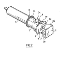
- la figure 2 est une perspective du dispositif monté sur une seringue à mandrin gazeux, le piston étant au repos ;
- la figure 3 est une perspective du dispositif monté sur une seringue à mandrin gazeux, le piston étant tiré, et
- la figure 4 est une perspective du dispositif monté sur une seringue à mandrin liquide, le piston étant au repos.
- Figure 1 is a perspective of the device;
- Figure 2 is a perspective view of the device mounted on a syringe with a gas mandrel, the piston being at rest;
- FIG. 3 is a perspective view of the device mounted on a gas mandrel syringe, the piston being pulled, and
- Figure 4 is a perspective of the device mounted on a liquid mandrel syringe, the piston being at rest.
Le dispositif représenté en perspective sur la figure 1 est un corps unitaire qui comprend une embase cylindrique (1), un chapeau poussoir (2) et deux bras de liaison (3) montés en parallèle qui relient le chapeau au poussoir. De préférence, le chapeau et les deux bras viennent ensemble de fabrication.The device represented in perspective on the FIG. 1 is a unitary body which comprises a base cylinder (1), a pusher cap (2) and two arms of link (3) connected in parallel which connect the cap to the button. Preferably, the hat and both arms come together manufacturing.
A leurs extrémités libres, les bras sont fixés à l'embase. Dans l'exemple représenté, les bras présentent une partie centrale amincie (3a) entre deux extrémités (3b, 3c) pour la liaison des bras au chapeau et à l'embase.At their free ends, the arms are attached to the base. In the example shown, the arms present a thinned central portion (3a) between two ends (3b, 3c) for the connection of the arms to the hat and the base.
Le chapeau (2) est prévu suffisamment large pour couvrir la tête du piston (7) de la seringue. De préférence, la face du chapeau qui est au contact de la tête du piston présente une collerette circulaire (2a) qui permet de centrer la tête du piston dans le chapeau.The cap (2) is provided wide enough for cover the plunger head (7) of the syringe. Of preferably, the face of the hat which is in contact with the piston head has a circular collar (2a) which makes it possible to center the piston head in the hat.
L'embase a toute longueur voulue, du simple anneau jusqu'au fourreau et le diamètre qui convient pour coulisser sur le corps tubulaire (5) de la seringue jusqu'à venir en butée sur le col (6) de ce corps.The base has any desired length, the simple ring up to the sheath and the proper diameter for slide on the tubular body (5) of the syringe until abutting on the neck (6) of this body.
Dans le cas représenté, l'embase constitue un fourreau qui peut être enfilé sur le corps de la seringue, au choix par l'une ou l'autre des deux extrémités opposées (1a, 1b) du fourreau, et les emplacements (4) de fixation des bras (3) sur le fourreau sont plus proches d'une extrémité de l'embase que de l'autre et constituent des pivots sur lesquels peuvent tourner les bras.In the case shown, the base constitutes a sheath that can be slipped on the body of the syringe, to be chosen by either of the two opposite ends (1a, 1b) of the sheath, and the locations (4) for attaching the arms (3) to the sheath are closer to one end of the base than the other and constitute pivots on which turn your arms.
Cette disposition avantageuse permet, avec les mêmes bras, de choisir la distance des pivots au chapeau entre une distance courte et une distance longue, selon que l'embase a été enfilée sur le corps tubulaire par son extrémité (1a) proche des pivots ou par son extrémité (1b) éloignée des pivots. Dans le cas de la figure 2, la distance des pivots au chapeau est courte et, pour passer à la distance longue (figure 4), il suffit de retourner l'embase et de basculer les bras de 180°.This advantageous arrangement allows, with the same arm, to choose the distance from the pivots to the hat between a short distance and a long distance, depending on whether the base has been threaded onto the tubular body by its end (1a) close to the pivots or by its end (1b) away from the pivots. In the case of Figure 2, the distance from the pivots to the hat is short and, to pass at the long distance (Figure 4), just flip the base and swing the arms by 180 °.
Le choix de la distance courte convient plus particulièrement au cas où le fluide à injecter est un gaz puisque la tension des bras élastiques n'a pas besoin d'être élevée pour l'expulsion du gaz et l'on a représenté sur les figures 2 et 3 une telle seringue équipée du dispositif de l'invention respectivement avec le piston (7) au repos (figure 2) et le piston tiré (figure 3).The choice of short distance is more suitable particularly in the case where the fluid to be injected is a gas since the tension of the elastic arms does not need to be high for the expulsion of gas and one has shown in Figures 2 and 3 such a syringe equipped with the device of the invention respectively with the piston (7) at rest (Figure 2) and the piston pulled (Figure 3).
Le choix de la distance longue convient plus particulièrement au cas où le fluide à injecter est un liquide qui nécessite une tension plus élevée des bras élastiques et l'on a représenté sur la figure 4 une telle seringue équipée du dispositif selon l'invention, avec le piston (7) au repos.The choice of the long distance is more suitable particularly in the case where the fluid to be injected is a liquid that requires a higher tension of the arms elastic members and there is shown in Figure 4 such syringe equipped with the device according to the invention, with the piston (7) at rest.
Avantageusement le fourreau présente à chaque extrémité des crochets (8) pour agripper la collerette (6) de la seringue de façon à solidariser le fourreau et la seringue, notamment pour un usage unique. Advantageously the sheath presents to each end of the hooks (8) to grip the collar (6) of the syringe so as to secure the sheath and the syringe, especially for a single use.
Il est en effet prévu de préférence que la seringue équipée soit à usage unique, l'utilisateur décidant a priori d'injecter un mandrin gazeux ou un mandrin liquide et plaçant définitivement le fourreau dans la position qui convient pour l'usage envisagé.It is in fact preferably provided that the syringe equipped either for single use, the user deciding to priori to inject a gas mandrel or a liquid mandrel and definitely placing the sheath in the position suitable for the intended use.
Le dispositif est susceptible de nombreuses variantes, dans lesquelles, par exemple :
- les bras ne sont élastiques que sur une partie de leur longueur ;
- l'embase présente plusieurs endroits de fixation possible répartis dans la longueur de l'embase pour les liens à extension élastique.
- the arms are elastic only for a part of their length;
- the base has several possible fixing locations distributed in the length of the base for the elastically extending links.
L'invention n'est pas limitée à la réalisation qui a été décrite.The invention is not limited to the realization which has has been described.
Claims (10)
Priority Applications (1)
| Application Number | Priority Date | Filing Date | Title |
|---|---|---|---|
| PL04291754T PL1495776T3 (en) | 2003-07-11 | 2004-07-09 | Device for medical syringe for automatically subjecting its piston to a positive pressure |
Applications Claiming Priority (2)
| Application Number | Priority Date | Filing Date | Title |
|---|---|---|---|
| ES200301669U | 2003-07-11 | ||
| ES200301669U ES1055061Y (en) | 2003-07-11 | 2003-07-11 | SYRINGE WITH CONTINUOUS POSITIVE PRESSURE. |
Publications (2)
| Publication Number | Publication Date |
|---|---|
| EP1495776A1 true EP1495776A1 (en) | 2005-01-12 |
| EP1495776B1 EP1495776B1 (en) | 2008-12-03 |
Family
ID=29763167
Family Applications (1)
| Application Number | Title | Priority Date | Filing Date |
|---|---|---|---|
| EP04291754A Active EP1495776B1 (en) | 2003-07-11 | 2004-07-09 | Device for medical syringe for automatically subjecting its piston to a positive pressure |
Country Status (7)
| Country | Link |
|---|---|
| EP (1) | EP1495776B1 (en) |
| AT (1) | ATE415988T1 (en) |
| DE (1) | DE602004018066D1 (en) |
| DK (1) | DK1495776T3 (en) |
| ES (2) | ES1055061Y (en) |
| PL (1) | PL1495776T3 (en) |
| PT (1) | PT1495776E (en) |
Cited By (3)
| Publication number | Priority date | Publication date | Assignee | Title |
|---|---|---|---|---|
| EP2766070A4 (en) * | 2011-10-10 | 2015-07-08 | Epikwik Internat Ag | Device for a syringe |
| ITUB20154926A1 (en) * | 2015-10-30 | 2016-01-30 | Bcs S R L | Disposable syringe with automatic discharge device |
| US11701469B2 (en) | 2019-04-25 | 2023-07-18 | Matthew John Petrides | Devices and methods for conduit distention |
Families Citing this family (1)
| Publication number | Priority date | Publication date | Assignee | Title |
|---|---|---|---|---|
| ES1060690Y (en) | 2005-07-05 | 2006-02-01 | Prieto Carracedo Jose Luis | INJECTOR DEVICE FOR SYRINGES |
Citations (5)
| Publication number | Priority date | Publication date | Assignee | Title |
|---|---|---|---|---|
| US4381006A (en) * | 1980-11-10 | 1983-04-26 | Abbott Laboratories | Continuous low flow rate fluid dispenser |
| US5024662A (en) * | 1990-03-13 | 1991-06-18 | Menes Cesar M | Resistance syringe for epidural anesthesia |
| US5531696A (en) * | 1993-12-13 | 1996-07-02 | Menes; Cesar M. | Elastomeric driver for epidural resistance syringe |
| US5643213A (en) * | 1994-03-09 | 1997-07-01 | I-Flow Corporation | Elastomeric syringe actuation device |
| US5944693A (en) * | 1998-08-17 | 1999-08-31 | Jacobs; Warren A | Syringe assembly and associated syringe biasing device |
-
2003
- 2003-07-11 ES ES200301669U patent/ES1055061Y/en not_active Expired - Fee Related
-
2004
- 2004-07-09 DE DE602004018066T patent/DE602004018066D1/en active Active
- 2004-07-09 AT AT04291754T patent/ATE415988T1/en active
- 2004-07-09 DK DK04291754T patent/DK1495776T3/en active
- 2004-07-09 PL PL04291754T patent/PL1495776T3/en unknown
- 2004-07-09 ES ES04291754T patent/ES2316940T3/en active Active
- 2004-07-09 EP EP04291754A patent/EP1495776B1/en active Active
- 2004-07-09 PT PT04291754T patent/PT1495776E/en unknown
Patent Citations (5)
| Publication number | Priority date | Publication date | Assignee | Title |
|---|---|---|---|---|
| US4381006A (en) * | 1980-11-10 | 1983-04-26 | Abbott Laboratories | Continuous low flow rate fluid dispenser |
| US5024662A (en) * | 1990-03-13 | 1991-06-18 | Menes Cesar M | Resistance syringe for epidural anesthesia |
| US5531696A (en) * | 1993-12-13 | 1996-07-02 | Menes; Cesar M. | Elastomeric driver for epidural resistance syringe |
| US5643213A (en) * | 1994-03-09 | 1997-07-01 | I-Flow Corporation | Elastomeric syringe actuation device |
| US5944693A (en) * | 1998-08-17 | 1999-08-31 | Jacobs; Warren A | Syringe assembly and associated syringe biasing device |
Cited By (3)
| Publication number | Priority date | Publication date | Assignee | Title |
|---|---|---|---|---|
| EP2766070A4 (en) * | 2011-10-10 | 2015-07-08 | Epikwik Internat Ag | Device for a syringe |
| ITUB20154926A1 (en) * | 2015-10-30 | 2016-01-30 | Bcs S R L | Disposable syringe with automatic discharge device |
| US11701469B2 (en) | 2019-04-25 | 2023-07-18 | Matthew John Petrides | Devices and methods for conduit distention |
Also Published As
| Publication number | Publication date |
|---|---|
| ES2316940T3 (en) | 2009-04-16 |
| ES1055061Y (en) | 2004-01-16 |
| ES1055061U (en) | 2003-10-01 |
| ATE415988T1 (en) | 2008-12-15 |
| EP1495776B1 (en) | 2008-12-03 |
| DK1495776T3 (en) | 2009-03-09 |
| DE602004018066D1 (en) | 2009-01-15 |
| PT1495776E (en) | 2009-02-17 |
| PL1495776T3 (en) | 2009-06-30 |
Similar Documents
| Publication | Publication Date | Title |
|---|---|---|
| EP1420849B1 (en) | Medical kit comprising a catheter, a needle and its case | |
| EP1933743B1 (en) | Accessory for tensioning a flexible link | |
| FR2760345A1 (en) | Bottle-carrier suspended from cord round neck of user | |
| WO1990004988A1 (en) | Syringe guide with a device for adjusting the depth of penetration of the needle into the skin | |
| EP2037864B1 (en) | Fixture for mounting a gastrostomy tube on a base, and gastrostomy button | |
| FR2923721A1 (en) | INFLATION DEVICE FOR BALLOON. | |
| EP1251966B1 (en) | Fluid product dispenser with gripping member | |
| EP0558731A1 (en) | Walking aid of the crutch or cane type | |
| EP1495776B1 (en) | Device for medical syringe for automatically subjecting its piston to a positive pressure | |
| EP3374007B1 (en) | Syringe | |
| EP0267827A1 (en) | Grip for an exercising apparatus | |
| CH664891A5 (en) | LIFTING STRAP AND LIFTING APPARATUS FOR INVALID PROVIDED WITH SAID STRAP. | |
| EP0202287B1 (en) | Ski stick provided with a device for adjusting the length of the wrist strap | |
| FR2622804A1 (en) | Non-reusable syringe | |
| FR2626661A1 (en) | ASSEMBLY DEVICE FOR HEAT EXCHANGER ASSEMBLY / TUBULAR CONNECTION | |
| EP0468899B1 (en) | System to detachably connect a part to a fixed member, said part being in particular a wheel-cover | |
| CH714646A2 (en) | Device for fixing a bracelet. | |
| FR2853526A1 (en) | BOTTLE SUPPORT | |
| FR2598066A1 (en) | Umbrella-carrying device | |
| EP1238758A1 (en) | Assisting device for mounting a fastening clip | |
| FR2680100A1 (en) | Non-slip foot strap for massaging the sole of the foot | |
| FR2512771A1 (en) | DEVICE FOR FIXING THE BASE OF A CYCLIST ON A PEDAL, WITH AUTOMATIC RELEASE | |
| FR2818040A1 (en) | Tool for stripping insulation from electrical cables has gripping organ which is moved toward blade and mechanism enclosed by handle shaped with ergonomic contours in both planes | |
| FR2801170A1 (en) | Equipment, for capturing remote bodies, consists of tubular handle with one end fitted with loop, with ends of loop passing through handle to sliding mechanism, to adjust size of loop | |
| FR3106864A1 (en) | AIR INFLATION DEVICE WITH A ROTATING MANOMETER |
Legal Events
| Date | Code | Title | Description |
|---|---|---|---|
| PUAI | Public reference made under article 153(3) epc to a published international application that has entered the european phase |
Free format text: ORIGINAL CODE: 0009012 |
|
| AK | Designated contracting states |
Kind code of ref document: A1 Designated state(s): AT BE BG CH CY CZ DE DK EE ES FI FR GB GR HU IE IT LI LU MC NL PL PT RO SE SI SK TR |
|
| AX | Request for extension of the european patent |
Extension state: AL HR LT LV MK |
|
| 17P | Request for examination filed |
Effective date: 20050708 |
|
| AKX | Designation fees paid |
Designated state(s): AT BE BG CH CY CZ DE DK EE ES FI FR GB GR HU IE IT LI LU MC NL PL PT RO SE SI SK TR |
|
| 17Q | First examination report despatched |
Effective date: 20070313 |
|
| GRAP | Despatch of communication of intention to grant a patent |
Free format text: ORIGINAL CODE: EPIDOSNIGR1 |
|
| GRAS | Grant fee paid |
Free format text: ORIGINAL CODE: EPIDOSNIGR3 |
|
| GRAA | (expected) grant |
Free format text: ORIGINAL CODE: 0009210 |
|
| AK | Designated contracting states |
Kind code of ref document: B1 Designated state(s): AT BE BG CH CY CZ DE DK EE ES FI FR GB GR HU IE IT LI LU MC NL PL PT RO SE SI SK TR |
|
| REG | Reference to a national code |
Ref country code: GB Ref legal event code: FG4D Free format text: NOT ENGLISH |
|
| REG | Reference to a national code |
Ref country code: CH Ref legal event code: EP |
|
| REG | Reference to a national code |
Ref country code: IE Ref legal event code: FG4D Free format text: LANGUAGE OF EP DOCUMENT: FRENCH |
|
| REF | Corresponds to: |
Ref document number: 602004018066 Country of ref document: DE Date of ref document: 20090115 Kind code of ref document: P |
|
| REG | Reference to a national code |
Ref country code: CH Ref legal event code: NV Representative=s name: MICHELI & CIE SA |
|
| REG | Reference to a national code |
Ref country code: PT Ref legal event code: SC4A Free format text: AVAILABILITY OF NATIONAL TRANSLATION Effective date: 20090209 |
|
| REG | Reference to a national code |
Ref country code: SE Ref legal event code: TRGR |
|
| REG | Reference to a national code |
Ref country code: DK Ref legal event code: T3 |
|
| REG | Reference to a national code |
Ref country code: ES Ref legal event code: FG2A Ref document number: 2316940 Country of ref document: ES Kind code of ref document: T3 |
|
| PG25 | Lapsed in a contracting state [announced via postgrant information from national office to epo] |
Ref country code: SI Free format text: LAPSE BECAUSE OF FAILURE TO SUBMIT A TRANSLATION OF THE DESCRIPTION OR TO PAY THE FEE WITHIN THE PRESCRIBED TIME-LIMIT Effective date: 20081203 |
|
| REG | Reference to a national code |
Ref country code: PL Ref legal event code: T3 |
|
| PG25 | Lapsed in a contracting state [announced via postgrant information from national office to epo] |
Ref country code: EE Free format text: LAPSE BECAUSE OF FAILURE TO SUBMIT A TRANSLATION OF THE DESCRIPTION OR TO PAY THE FEE WITHIN THE PRESCRIBED TIME-LIMIT Effective date: 20081203 Ref country code: RO Free format text: LAPSE BECAUSE OF FAILURE TO SUBMIT A TRANSLATION OF THE DESCRIPTION OR TO PAY THE FEE WITHIN THE PRESCRIBED TIME-LIMIT Effective date: 20081203 Ref country code: BG Free format text: LAPSE BECAUSE OF FAILURE TO SUBMIT A TRANSLATION OF THE DESCRIPTION OR TO PAY THE FEE WITHIN THE PRESCRIBED TIME-LIMIT Effective date: 20090303 |
|
| PG25 | Lapsed in a contracting state [announced via postgrant information from national office to epo] |
Ref country code: CZ Free format text: LAPSE BECAUSE OF FAILURE TO SUBMIT A TRANSLATION OF THE DESCRIPTION OR TO PAY THE FEE WITHIN THE PRESCRIBED TIME-LIMIT Effective date: 20081203 |
|
| PG25 | Lapsed in a contracting state [announced via postgrant information from national office to epo] |
Ref country code: SK Free format text: LAPSE BECAUSE OF FAILURE TO SUBMIT A TRANSLATION OF THE DESCRIPTION OR TO PAY THE FEE WITHIN THE PRESCRIBED TIME-LIMIT Effective date: 20081203 |
|
| PLBE | No opposition filed within time limit |
Free format text: ORIGINAL CODE: 0009261 |
|
| STAA | Information on the status of an ep patent application or granted ep patent |
Free format text: STATUS: NO OPPOSITION FILED WITHIN TIME LIMIT |
|
| 26N | No opposition filed |
Effective date: 20090904 |
|
| PG25 | Lapsed in a contracting state [announced via postgrant information from national office to epo] |
Ref country code: MC Free format text: LAPSE BECAUSE OF NON-PAYMENT OF DUE FEES Effective date: 20090731 |
|
| PG25 | Lapsed in a contracting state [announced via postgrant information from national office to epo] |
Ref country code: GR Free format text: LAPSE BECAUSE OF FAILURE TO SUBMIT A TRANSLATION OF THE DESCRIPTION OR TO PAY THE FEE WITHIN THE PRESCRIBED TIME-LIMIT Effective date: 20090304 |
|
| PG25 | Lapsed in a contracting state [announced via postgrant information from national office to epo] |
Ref country code: LU Free format text: LAPSE BECAUSE OF NON-PAYMENT OF DUE FEES Effective date: 20090709 |
|
| PG25 | Lapsed in a contracting state [announced via postgrant information from national office to epo] |
Ref country code: HU Free format text: LAPSE BECAUSE OF FAILURE TO SUBMIT A TRANSLATION OF THE DESCRIPTION OR TO PAY THE FEE WITHIN THE PRESCRIBED TIME-LIMIT Effective date: 20090604 |
|
| PG25 | Lapsed in a contracting state [announced via postgrant information from national office to epo] |
Ref country code: TR Free format text: LAPSE BECAUSE OF FAILURE TO SUBMIT A TRANSLATION OF THE DESCRIPTION OR TO PAY THE FEE WITHIN THE PRESCRIBED TIME-LIMIT Effective date: 20081203 |
|
| PG25 | Lapsed in a contracting state [announced via postgrant information from national office to epo] |
Ref country code: CY Free format text: LAPSE BECAUSE OF FAILURE TO SUBMIT A TRANSLATION OF THE DESCRIPTION OR TO PAY THE FEE WITHIN THE PRESCRIBED TIME-LIMIT Effective date: 20081203 |
|
| PGFP | Annual fee paid to national office [announced via postgrant information from national office to epo] |
Ref country code: CH Payment date: 20110715 Year of fee payment: 8 |
|
| PGFP | Annual fee paid to national office [announced via postgrant information from national office to epo] |
Ref country code: NL Payment date: 20120629 Year of fee payment: 9 Ref country code: DK Payment date: 20120625 Year of fee payment: 9 |
|
| PGFP | Annual fee paid to national office [announced via postgrant information from national office to epo] |
Ref country code: PL Payment date: 20120612 Year of fee payment: 9 Ref country code: FI Payment date: 20120626 Year of fee payment: 9 |
|
| PGFP | Annual fee paid to national office [announced via postgrant information from national office to epo] |
Ref country code: SE Payment date: 20120719 Year of fee payment: 9 |
|
| PGFP | Annual fee paid to national office [announced via postgrant information from national office to epo] |
Ref country code: BE Payment date: 20120726 Year of fee payment: 9 |
|
| PGFP | Annual fee paid to national office [announced via postgrant information from national office to epo] |
Ref country code: PT Payment date: 20120109 Year of fee payment: 9 |
|
| PGFP | Annual fee paid to national office [announced via postgrant information from national office to epo] |
Ref country code: AT Payment date: 20120626 Year of fee payment: 9 |
|
| REG | Reference to a national code |
Ref country code: PT Ref legal event code: MM4A Free format text: LAPSE DUE TO NON-PAYMENT OF FEES Effective date: 20140109 |
|
| BERE | Be: lapsed |
Owner name: VYGON Effective date: 20130731 |
|
| REG | Reference to a national code |
Ref country code: NL Ref legal event code: V1 Effective date: 20140201 |
|
| REG | Reference to a national code |
Ref country code: DK Ref legal event code: EBP Effective date: 20130731 |
|
| REG | Reference to a national code |
Ref country code: CH Ref legal event code: PL |
|
| REG | Reference to a national code |
Ref country code: SE Ref legal event code: EUG |
|
| REG | Reference to a national code |
Ref country code: AT Ref legal event code: MM01 Ref document number: 415988 Country of ref document: AT Kind code of ref document: T Effective date: 20130709 |
|
| PG25 | Lapsed in a contracting state [announced via postgrant information from national office to epo] |
Ref country code: FI Free format text: LAPSE BECAUSE OF NON-PAYMENT OF DUE FEES Effective date: 20130709 Ref country code: BE Free format text: LAPSE BECAUSE OF NON-PAYMENT OF DUE FEES Effective date: 20130731 Ref country code: SE Free format text: LAPSE BECAUSE OF NON-PAYMENT OF DUE FEES Effective date: 20130710 Ref country code: LI Free format text: LAPSE BECAUSE OF NON-PAYMENT OF DUE FEES Effective date: 20130731 Ref country code: NL Free format text: LAPSE BECAUSE OF NON-PAYMENT OF DUE FEES Effective date: 20140201 Ref country code: CH Free format text: LAPSE BECAUSE OF NON-PAYMENT OF DUE FEES Effective date: 20130731 |
|
| PG25 | Lapsed in a contracting state [announced via postgrant information from national office to epo] |
Ref country code: AT Free format text: LAPSE BECAUSE OF NON-PAYMENT OF DUE FEES Effective date: 20130709 |
|
| PG25 | Lapsed in a contracting state [announced via postgrant information from national office to epo] |
Ref country code: PT Free format text: LAPSE BECAUSE OF NON-PAYMENT OF DUE FEES Effective date: 20140109 |
|
| PGFP | Annual fee paid to national office [announced via postgrant information from national office to epo] |
Ref country code: IE Payment date: 20140627 Year of fee payment: 11 |
|
| PG25 | Lapsed in a contracting state [announced via postgrant information from national office to epo] |
Ref country code: DK Free format text: LAPSE BECAUSE OF NON-PAYMENT OF DUE FEES Effective date: 20130731 |
|
| PGFP | Annual fee paid to national office [announced via postgrant information from national office to epo] |
Ref country code: DE Payment date: 20140711 Year of fee payment: 11 |
|
| REG | Reference to a national code |
Ref country code: PL Ref legal event code: LAPE |
|
| PG25 | Lapsed in a contracting state [announced via postgrant information from national office to epo] |
Ref country code: PL Free format text: LAPSE BECAUSE OF NON-PAYMENT OF DUE FEES Effective date: 20130709 |
|
| PGFP | Annual fee paid to national office [announced via postgrant information from national office to epo] |
Ref country code: GB Payment date: 20140717 Year of fee payment: 11 |
|
| PGFP | Annual fee paid to national office [announced via postgrant information from national office to epo] |
Ref country code: IT Payment date: 20140716 Year of fee payment: 11 |
|
| REG | Reference to a national code |
Ref country code: DE Ref legal event code: R119 Ref document number: 602004018066 Country of ref document: DE |
|
| GBPC | Gb: european patent ceased through non-payment of renewal fee |
Effective date: 20150709 |
|
| REG | Reference to a national code |
Ref country code: IE Ref legal event code: MM4A |
|
| PG25 | Lapsed in a contracting state [announced via postgrant information from national office to epo] |
Ref country code: IT Free format text: LAPSE BECAUSE OF NON-PAYMENT OF DUE FEES Effective date: 20150709 Ref country code: DE Free format text: LAPSE BECAUSE OF NON-PAYMENT OF DUE FEES Effective date: 20160202 Ref country code: GB Free format text: LAPSE BECAUSE OF NON-PAYMENT OF DUE FEES Effective date: 20150709 |
|
| REG | Reference to a national code |
Ref country code: FR Ref legal event code: PLFP Year of fee payment: 13 |
|
| PG25 | Lapsed in a contracting state [announced via postgrant information from national office to epo] |
Ref country code: IE Free format text: LAPSE BECAUSE OF NON-PAYMENT OF DUE FEES Effective date: 20150709 |
|
| REG | Reference to a national code |
Ref country code: FR Ref legal event code: PLFP Year of fee payment: 14 |
|
| REG | Reference to a national code |
Ref country code: FR Ref legal event code: PLFP Year of fee payment: 15 |
|
| P01 | Opt-out of the competence of the unified patent court (upc) registered |
Effective date: 20230428 |
|
| PGFP | Annual fee paid to national office [announced via postgrant information from national office to epo] |
Ref country code: FR Payment date: 20230614 Year of fee payment: 20 |
|
| PGFP | Annual fee paid to national office [announced via postgrant information from national office to epo] |
Ref country code: ES Payment date: 20230807 Year of fee payment: 20 |