EP1493869A1 - Blockwall and building element for its construction - Google Patents
Blockwall and building element for its construction Download PDFInfo
- Publication number
- EP1493869A1 EP1493869A1 EP03405482A EP03405482A EP1493869A1 EP 1493869 A1 EP1493869 A1 EP 1493869A1 EP 03405482 A EP03405482 A EP 03405482A EP 03405482 A EP03405482 A EP 03405482A EP 1493869 A1 EP1493869 A1 EP 1493869A1
- Authority
- EP
- European Patent Office
- Prior art keywords
- element block
- block wall
- component
- wall according
- cam
- Prior art date
- Legal status (The legal status is an assumption and is not a legal conclusion. Google has not performed a legal analysis and makes no representation as to the accuracy of the status listed.)
- Withdrawn
Links
Images
Classifications
-
- E—FIXED CONSTRUCTIONS
- E01—CONSTRUCTION OF ROADS, RAILWAYS, OR BRIDGES
- E01F—ADDITIONAL WORK, SUCH AS EQUIPPING ROADS OR THE CONSTRUCTION OF PLATFORMS, HELICOPTER LANDING STAGES, SIGNS, SNOW FENCES, OR THE LIKE
- E01F8/00—Arrangements for absorbing or reflecting air-transmitted noise from road or railway traffic
- E01F8/02—Arrangements for absorbing or reflecting air-transmitted noise from road or railway traffic specially adapted for sustaining vegetation or for accommodating plants ; Embankment-type or crib-type noise barriers; Retaining walls specially adapted to absorb or reflect noise
- E01F8/021—Arrangements for absorbing or reflecting air-transmitted noise from road or railway traffic specially adapted for sustaining vegetation or for accommodating plants ; Embankment-type or crib-type noise barriers; Retaining walls specially adapted to absorb or reflect noise with integral support structure
- E01F8/023—Arrangements for absorbing or reflecting air-transmitted noise from road or railway traffic specially adapted for sustaining vegetation or for accommodating plants ; Embankment-type or crib-type noise barriers; Retaining walls specially adapted to absorb or reflect noise with integral support structure made of stacked or staggered elements, e.g. hollow
Definitions
- the invention relates to an element block wall and in particular a heavyweight wall made of several prefabricated components, which are arranged in at least two superimposed and horizontally extending rows are arranged and one each facing the ground, a horizontal top, a bottom, a visible front and parallel to each other have running shock sides.
- Heavyweight walls of mentioned type have long been known.
- the shows EP 0 034 565 A of the Applicant a wall consisting of prefabricated, consists of rectangular concrete slabs and concrete hoops. The concrete slabs form wall panels and have at least one central top and two corner cutouts. The concrete hangers are down and stuck over the top of the wall plates and hold them together.
- To create a wall several different Crossbar required. In practice, would be to Creating a longer wall, such as a sound barrier five different elements required. Also if here the individual concrete elements cost-effective and easy to manufacture and relocate, so is due to the multiple different elements but a relatively complicated construction required.
- the invention is based on the object, an element block wall and in particular a heavyweight wall of the type mentioned create even more cost effective and easier to manufacture and too embarrassed.
- the task is solved by a generic wall, that the components are blocks and each at the bottom have a downwardly projecting thrust cam, which in the Components of the upper row at the back of at least one Component of the first row is pending.
- all blocks can be made equal be.
- very different types of walls can be used be built, for example, retaining walls, noise barriers or border fences. If the blocks are built on a slope, so can after creating the mass they will be charged immediately.
- the Cavities behind the blocks can be filled with soil, which makes greening much easier. An irrigation the plants is not required because the behind the cavities As a rule, the soil is not completely dry can. With the blocks can also be a vertical sound barrier being constructed. If necessary, the blocks with mortar or other means.
- the blocks so be arranged that there are gaps between them. These Gaps form windows through which sound passes behind the wall and can be absorbed with it.
- the invention also relates to an element for producing a Gravity dam.
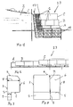
- the element block wall shown in Figures 1 and 2 is a Heavyweight wall 3 has three rows A, B and C, which are horizontally and in an arc. These rows A, B and C exist each of several prefabricated blocks 1, for example made of concrete and attached to a slope 2 are built.
- the wall 13 is back with a filling 17th made of water-permeable material, such as gravel and gravel backfilled.
- the bottom row A lies on a foundation 12, which has been created as usual.
- the prefabricated blocks 1 are preferably all the same and Form the wall 13. Further construction elements are not required.
- the blocks 1 can be seen each other as shown in Figures 1 and 2 be put.
- the weight of a block is for example about 1.5 tons. Are they according to Figure 1 on a slope. 2 built, so the blocks 1 are stable and must not be mentioned additionally fastened.
- the retaining wall 13 can thus be made same blocks 1 are constructed and has no additional Fasteners a high stability.
- the blocks 1 can be arranged so that there are gaps between them. In this case, the heavyweight wall 13 is permeable to water and a planting is possible.
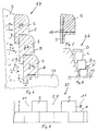
- the blocks 1, according to Figures 3 and 4 each have a Hang 2 facing back 3, a horizontal top 4, a bottom 5, a visible front 6 and parallel to each other extending shock sides 7 and 8. They each point on the bottom 5 a downwardly projecting thrust cam 9, the extends according to Figure 4 over the entire width of the back 3. Rear side of the push cam 9 is flush with the back 3.
- the push cam 9 has, according to FIG. 3, a thickness S, which is about 1/5 of the bar height R shown in Figure 4.
- the Height E of the push cam 9 is preferably in the range of 30 to 50 cm and is preferably about 40 cm.
- the bar height R is preferably in the range between 60 and 100 cm. In a Particularly preferred embodiment, the bolt height R is in the range between 70 and 90 cm. Is the bar height R 80 cm and the height E is 40 cm, so is the preferred total height of the block 1 120 cm.
- the blocks 1 are preferably reinforced in the region of the push cam 9, for example by means of an iron reinforcement 10. Thereby This results in a particularly high stability of the heavyweight wall 13th
- FIG. 6 is the weight of blocks 1 with K1 and K2 with K2 Force of the slope 2 on a heavyweight wall 14 schematically shown.
- K2 the forces K2
- the blocks 1 of the lowest Row A against the foundation 12 the B row 1 against the row A and the blocks 1 of the row C against the row B pressed.
- These forces are absorbed by the push cams 9, the back of the foundation 12 or the underlying Queue A or B are pending.
- the push cam 9 prevent it sure that the heavyweight wall 14 in Figure 6 after can tilt to the right. A tilt to the left is by the Hang 2 prevented.
- FIG. 7 shows a further variant of a heavyweight wall 15, in which the blocks 1 of the row B at a distance from each other are arranged that form 11 between these gaps. These gaps 11 may be greened and the sound absorption serve. Basically, the blocks 1 of the series A in Be spaced apart so that between them Form windows that sound absorbing.
- FIG. 8 shows a variant of a heavyweight wall 16, in which the row A 'made of blocks placed on the foundation 12 1, whose push cam 9 are directed upward. For the remaining rows B, C and D, the blocks 1 are as in FIG 6 oriented.
Abstract
Description
Die Erfindung betrifft eine Elementblockmauer und insbesondere eine Schwergewichtsmauer aus mehreren vorgefertigten Bauelementen, die in wenigstens zwei übereinander angeordneten und sich horizontal erstreckenden Reihen angeordnet sind und jeweils eine dem Erdreich zugewandte Rückseite, eine horizontale Oberseite, eine Unterseite, eine sichtbare Frontseite und parallel zueinander verlaufende Stossseiten aufweisen. Schwergewichtsmauern der genannten Art sind seit langem bekannt. Beispielsweise zeigt die EP 0 034 565 A des Anmelders eine Mauer, die aus vorgefertigten, rechteckigen Betonplatten und Betonbügeln besteht. Die Betonplatten bilden Wandplatten und weisen oben mindestens eine mittige und zwei Eckaussparungen auf. Die Betonbügel sind unten und oben über Stösse der Wandplatten gesteckt und halten diese zusammen. In der Regel sind zum Erstellen einer Mauer mehrere unterschiedliche Querbügel erforderlich. In der Praxis wären zum Erstellen einer längeren Mauer, beispielsweise einer Schallschutzmauer fünf unterschiedliche Elemente erforderlich. Auch wenn hier die einzelnen Betonelemente kostengünstig und einfach herzustellen und zu verlegen sind, so ist aufgrund der mehreren unterschiedlichen Elemente doch eine relativ aufwendige Bauweise erforderlich.The invention relates to an element block wall and in particular a heavyweight wall made of several prefabricated components, which are arranged in at least two superimposed and horizontally extending rows are arranged and one each facing the ground, a horizontal top, a bottom, a visible front and parallel to each other have running shock sides. Heavyweight walls of mentioned type have long been known. For example, the shows EP 0 034 565 A of the Applicant a wall consisting of prefabricated, consists of rectangular concrete slabs and concrete hoops. The concrete slabs form wall panels and have at least one central top and two corner cutouts. The concrete hangers are down and stuck over the top of the wall plates and hold them together. In general, to create a wall several different Crossbar required. In practice, would be to Creating a longer wall, such as a sound barrier five different elements required. Also if here the individual concrete elements cost-effective and easy to manufacture and relocate, so is due to the multiple different elements but a relatively complicated construction required.
Der Erfindung liegt die Aufgabe zugrunde, eine Elementblockmauer und insbesondere eine Schwergewichtsmauer der genannten Art zu schaffen, die noch kostengünstiger und einfacher herzustellen und zu verlegen ist. The invention is based on the object, an element block wall and in particular a heavyweight wall of the type mentioned create even more cost effective and easier to manufacture and too embarrassed.
Die Aufgabe ist bei einer gattungsgemässen Mauer dadurch gelöst, dass die Bauelmente Blöcke sind und jeweils an der Unterseite einen nach unten ragenden Schubnocken aufweisen, der bei den Bauelementen der oberen Reihe an der Rückseite wenigstens eines Bauelementes der ersten Reihe ansteht. Bei der erfindungsgemässen Schwergewichtsmauer können sämtliche Blöcke gleich ausgebildet sein. Trotzdem können sehr unterschiedliche Arten von Mauern aufgebaut werden, beispielsweise Stützmauern, Schallschutzwände oder Grenzzäune. Werden die Blöcke an einen Hang gebaut, so kann nach dem Erstellen der Masse diese sofort belastet werden. Die Hohlräume hinter den Blöcken können mit Erdreich verfüllt werden, was eine Begrünung wesentlich erleichtert. Eine Bewässerung der Pflanzen ist nicht erforderlich, da die hinter den Hohlräumen befindliche Erde in aller Regel nicht völlig austrocknen kann. Mit den Blöcken kann auch eine senkrechte Schallschutzmauer aufgebaut werden. Nötigenfalls können die Blöcke mit Mörtel oder anderen Mitteln miteinander verbunden werden.The task is solved by a generic wall, that the components are blocks and each at the bottom have a downwardly projecting thrust cam, which in the Components of the upper row at the back of at least one Component of the first row is pending. In the inventive Heavyweight wall, all blocks can be made equal be. Nevertheless, very different types of walls can be used be built, for example, retaining walls, noise barriers or border fences. If the blocks are built on a slope, so can after creating the mass they will be charged immediately. The Cavities behind the blocks can be filled with soil, which makes greening much easier. An irrigation the plants is not required because the behind the cavities As a rule, the soil is not completely dry can. With the blocks can also be a vertical sound barrier being constructed. If necessary, the blocks with mortar or other means.
Zur Begrünung und als Schallschutzgründen können die Blöcke so angeordnet werden, dass zwischen ihnen Lücken bestehen. Diese Lücken bilden Fenster, durch welche Schall hinter die Mauer gelangt und damit absorbiert werden kann.For greening and soundproofing reasons, the blocks so be arranged that there are gaps between them. These Gaps form windows through which sound passes behind the wall and can be absorbed with it.
Die Erfindung betrifft zudem ein Element zur Herstellung einer Schwergewichtsmauer.The invention also relates to an element for producing a Gravity dam.
Vorteilhafte Merkmale ergeben sich aus den abhängigen Patentansprüchen, der nachfolgenden Beschreibung sowie der Zeichnung.Advantageous features emerge from the dependent claims, the following description and the drawing.
Ausführungsbeispiele der Erfindung werden nachfolgend anhand der Zeichnung näher erläutert. Es zeigen:
Figur 1- eine teilweise geschnittene schematische Ansicht einer erfindungsgemässen Schwergewichtsmauer,
Figur 2- eine weitere Ansicht der Schwergewichtsmauer
gemäss
Figur 1, - Figuren 3 und 4
- Ansichten eines Bauelementes,
Figur 5- ein vertikaler Schnitt durch ein Bauelement,
Figur 6- ein vertikaler Schnitt durch eine Schwergewichtsmauer,
Figur 7- eine schematische Teilansicht einer Schwergewichtsmauer nach einer Variante und
Figur 8- schematisch eine Teilansicht einer weiteren Variante einer erfindungsgemässen Schwergewichtsmauer.
- FIG. 1
- a partially sectioned schematic view of an inventive gravity wall,
- FIG. 2
- another view of the heavyweight wall according to Figure 1,
- FIGS. 3 and 4
- Views of a component,
- FIG. 5
- a vertical section through a component,
- FIG. 6
- a vertical section through a heavyweight wall,
- FIG. 7
- a schematic partial view of a heavyweight wall according to a variant and
- FIG. 8
- schematically a partial view of another variant of an inventive heavyweight wall.
Die in den Figuren 1 und 2 gezeigte Elementblockmauer ist eine
Schwergewichtsmauer 3 weist drei Reihen A, B und C auf, die sich
horizontal und im Bogen erstrecken. Diese Reihen A, B und C bestehen
jeweils aus mehreren vorgefertigten Blöcken 1, die beispielsweise
aus Beton hergestellt sind und die an einen Hang 2
gebaut sind. Die Mauer 13 ist rückseitig mit einer Füllung 17
aus wasserdurchlässigem Material, beispielsweise Kies und Schotter
hinterfüllt. Die unterste Reihe A liegt auf einem Fundament
12 auf, das wie üblich erstellt worden ist.The element block wall shown in Figures 1 and 2 is a
Heavyweight wall 3 has three rows A, B and C, which are
horizontally and in an arc. These rows A, B and C exist
each of several
Die vorgefertigten Blöcke 1 sind vorzugsweise alle gleich und
bilden die Mauer 13. Weitere Bauelement sind nicht erforderlich.
Die Blöcke 1 können wie in den Figuren 1 und 2 ersichtlich aufeinander
gestellt werden. Das Gewicht eines Blockes beträgt beispielsweise
etwa 1,5 t. Sind sie gemäss Figur 1 an einem Hang 2
gebaut, so sind die Blöcke 1 stabil und müssen wie erwähnt nicht
zusätzlich befestigt werden. Die Stützmauer 13 kann somit aus
gleichen Blöcken 1 aufgebaut werden und besitzt ohne zusätzliche
Befestigungsmittel eine hohe Standfestigkeit. Die Blöcke 1 können
so angeordnet werden, dass zwischen ihnen Lücken bestehen.
In diesem Fall ist die Schwergewichtsmauer 13 wasserdurchlässig
und eine Bepflanzung ist möglich.The
Die Blöcke 1 weisen gemäss den Figuren 3 und 4 jeweils eine dem
Hang 2 zugewendete Rückseite 3, eine horizontale Oberseite 4,
eine Unterseite 5, eine sichtbare Frontseite 6 und parallel zueinander
verlaufende Stossseiten 7 und 8 auf. Sie weisen jeweils
an der Unterseite 5 einen unten ragenden Schubnocken 9 auf, der
sich gemäss Figur 4 über die gesamte Breite der Rückseite 3 erstreckt.
Rückseitig ist der Schubnocken 9 bündig zur Rückseite
3. Der Schubnocken 9 weist gemäss Figur 3 eine Stärke S auf,
die etwa 1/5 der in Figur 4 gezeigten Riegelhöhe R beträgt. Die
Höhe E des Schubnockens 9 liegt vorzugsweise im Bereich von 30
bis 50 cm und beträgt vorzugsweise etwa 40 cm. Die Riegelhöhe R
liegt vorzugsweise im Bereich zwischen 60 und 100 cm. In einer
besonders bevorzugten Ausführung liegt die Riegelhöhe R im Bereich
zwischen 70 und 90 cm. Beträgt die Riegelhöhe R 80 cm und
die Höhe E 40 cm, so beträgt die bevorzugte Gesamthöhe des Blockes
1 120 cm.The
Die Blöcke 1 sind vorzugsweise im Bereich des Schubnockens 9 armiert,
beispielsweise mittels einer Eisenarmierung 10. Dadurch
ergibt sich eine besonders hohe Stabilität der Schwergewichtsmauer
13.The
Die Figur 6 ist mit K1 das Gewicht der Blöcke 1 und mit K2 die
Kraft des Hanges 2 auf eine Schwergewichtsmauer 14 schematisch
dargestellt. Durch die Kräfte K2 werden die Blöcke 1 der untersten
Reihe A gegen das Fundament 12, die Blöcke 1 der Reihe B gegen
die Reihe A und die Blöcke 1 der Reihe C gegen die Reihe B
angepresst. Diese Kräfte werden von den Schubnocken 9 aufgenommen,
die rückseitig am Fundament 12 oder an der darunter liegenden
Reihe A bzw. B anstehen. Die Schubnocken 9 verhindern damit
sicher, dass die Schwergewichtsmauer 14 in Figur 6 sich nach
rechts neigen kann. Eine Neigung nach links wird durch den
Hang 2 verhindert.FIG. 6 is the weight of
Die Figur 7 zeigt eine weitere Variante einer Schwergewichtsmauer
15, bei welcher die Blöcke 1 der Reihe B so im Abstand zueinander
angeordnet sind, dass sich zwischen diesen Lücken 11 bilden.
Diese Lücken 11 können begrünt sein und der Schallabsorption
dienen. Grundsätzlich können auch die Blöcke 1 der Reihe A im
Abstand zueinander angeordnet sein, sodass sich zwischen diesen
Fenster bilden, die schallabsorbierend wirken.FIG. 7 shows a further variant of a
Die Figur 8 zeigt eine Variante einer Schwergewichtsmauer 16,
bei welcher die auf das Fundament 12 gestellte Reihe A' aus Blöcken
1 besteht, deren Schubnocken 9 nach oben gerichtet sind.
Bei den übrigen Reihen B, C und D sind die Blöcke 1 wie in Figur
6 gezeigt orientiert.FIG. 8 shows a variant of a
Claims (15)
Priority Applications (1)
| Application Number | Priority Date | Filing Date | Title |
|---|---|---|---|
| EP03405482A EP1493869A1 (en) | 2003-06-30 | 2003-06-30 | Blockwall and building element for its construction |
Applications Claiming Priority (1)
| Application Number | Priority Date | Filing Date | Title |
|---|---|---|---|
| EP03405482A EP1493869A1 (en) | 2003-06-30 | 2003-06-30 | Blockwall and building element for its construction |
Publications (1)
| Publication Number | Publication Date |
|---|---|
| EP1493869A1 true EP1493869A1 (en) | 2005-01-05 |
Family
ID=33427280
Family Applications (1)
| Application Number | Title | Priority Date | Filing Date |
|---|---|---|---|
| EP03405482A Withdrawn EP1493869A1 (en) | 2003-06-30 | 2003-06-30 | Blockwall and building element for its construction |
Country Status (1)
| Country | Link |
|---|---|
| EP (1) | EP1493869A1 (en) |
Citations (6)
| Publication number | Priority date | Publication date | Assignee | Title |
|---|---|---|---|---|
| US2313363A (en) * | 1940-07-02 | 1943-03-09 | George H Schmitt | Retaining wall and block for the same |
| EP0034565A1 (en) | 1980-02-11 | 1981-08-26 | Martin Mannhart | Wall built up with elements |
| CA1188116A (en) * | 1983-05-13 | 1985-06-04 | Evercrete Limited | Component for retaining walls and the like |
| US4711606A (en) * | 1985-02-18 | 1987-12-08 | Sf-Vollverbundstein-Kooperation Gmbh | Shaped (concrete) block for retaining walls and also a retaining wall |
| CH663437A5 (en) * | 1984-06-21 | 1987-12-15 | Carl Schiffer | Slope block |
| US6312197B1 (en) * | 1989-09-28 | 2001-11-06 | Anchor Wall Systems, Inc. | Composite masonry block |
-
2003
- 2003-06-30 EP EP03405482A patent/EP1493869A1/en not_active Withdrawn
Patent Citations (6)
| Publication number | Priority date | Publication date | Assignee | Title |
|---|---|---|---|---|
| US2313363A (en) * | 1940-07-02 | 1943-03-09 | George H Schmitt | Retaining wall and block for the same |
| EP0034565A1 (en) | 1980-02-11 | 1981-08-26 | Martin Mannhart | Wall built up with elements |
| CA1188116A (en) * | 1983-05-13 | 1985-06-04 | Evercrete Limited | Component for retaining walls and the like |
| CH663437A5 (en) * | 1984-06-21 | 1987-12-15 | Carl Schiffer | Slope block |
| US4711606A (en) * | 1985-02-18 | 1987-12-08 | Sf-Vollverbundstein-Kooperation Gmbh | Shaped (concrete) block for retaining walls and also a retaining wall |
| US6312197B1 (en) * | 1989-09-28 | 2001-11-06 | Anchor Wall Systems, Inc. | Composite masonry block |
Similar Documents
| Publication | Publication Date | Title |
|---|---|---|
| EP0170113B1 (en) | Building block | |
| DE2519232C3 (en) | Plantable retaining wall | |
| EP2060694B1 (en) | Building wall element | |
| DE3025870A1 (en) | Vegetation supporting retaining wall hollow block - is trough shaped with sloping interfacing lengthways sides | |
| DE102006051707A1 (en) | Gabion wall for use as sound insulation wall, has monolithic concrete core extending over entire length of gabion wall in interior of gabion wall, and enclosed by natural stone layering and filler material layering | |
| EP0234175A1 (en) | Building set for the erection of walls | |
| DE2718290A1 (en) | Wall with terraces for growing plants - has lengthways units with parapet and base panel overlapped by support blocks | |
| DE7830516U1 (en) | Prefabricated building element for walls | |
| EP1283304B1 (en) | Noise barrier wall from fence elements | |
| DE2532520C3 (en) | Protection device, in particular soundproofing device and slope fastening for roads, consisting of prefabricated components made of artificial stone, concrete or the like | |
| EP0024500B1 (en) | Concrete building element | |
| EP3486379A1 (en) | Wall structure in monolithic design for completing a system of plastic-reinforced soil and grid structure for same as functional location | |
| EP0058731B1 (en) | Wall composed of a plurality of construction elements | |
| DE202005018509U1 (en) | Fence has mesh grids supported on posts to define interspace filled with bulk loose materials such as natural stones | |
| EP0562154A1 (en) | Noise protection wall and slope stabilisation consisting of wire-mesh mats | |
| EP1493869A1 (en) | Blockwall and building element for its construction | |
| EP0286957B1 (en) | Vegetation-sustaining noise barrier | |
| EP0452744B1 (en) | Plant accommodating noise protection wall | |
| DE4132321A1 (en) | KIT FOR CHILDREN'S PLAYGROUNDS FOR BUILDING TOYS | |
| AT398098B (en) | Slope sheeting for embankments | |
| DE19710129A1 (en) | Artificial earth bank with vegetation bed | |
| DE8532773U1 (en) | Large-format shaped concrete block for the erection of vertical, plantable visible and / or soundproof walls | |
| EP0294778B1 (en) | Protective wall-element | |
| CH616189A5 (en) | Noise-protection wall | |
| DE1941076A1 (en) | Lock for torrent barriers |
Legal Events
| Date | Code | Title | Description |
|---|---|---|---|
| PUAI | Public reference made under article 153(3) epc to a published international application that has entered the european phase |
Free format text: ORIGINAL CODE: 0009012 |
|
| AK | Designated contracting states |
Kind code of ref document: A1 Designated state(s): AT BE BG CH CY CZ DE DK EE ES FI FR GB GR HU IE IT LI LU MC NL PT RO SE SI SK TR |
|
| AX | Request for extension of the european patent |
Extension state: AL LT LV MK |
|
| STAA | Information on the status of an ep patent application or granted ep patent |
Free format text: STATUS: THE APPLICATION HAS BEEN WITHDRAWN |
|
| 18W | Application withdrawn |
Effective date: 20050525 |