EP1493587A2 - Ink cartridge, detection device for cartridge identification and ink level detection, and image formation apparatus comprising thereof - Google Patents
Ink cartridge, detection device for cartridge identification and ink level detection, and image formation apparatus comprising thereof Download PDFInfo
- Publication number
- EP1493587A2 EP1493587A2 EP04253896A EP04253896A EP1493587A2 EP 1493587 A2 EP1493587 A2 EP 1493587A2 EP 04253896 A EP04253896 A EP 04253896A EP 04253896 A EP04253896 A EP 04253896A EP 1493587 A2 EP1493587 A2 EP 1493587A2
- Authority
- EP
- European Patent Office
- Prior art keywords
- ink
- ink cartridge
- detection
- detection target
- amount
- Prior art date
- Legal status (The legal status is an assumption and is not a legal conclusion. Google has not performed a legal analysis and makes no representation as to the accuracy of the status listed.)
- Granted
Links
- 238000001514 detection method Methods 0.000 title claims abstract description 524
- 230000015572 biosynthetic process Effects 0.000 title claims abstract description 49
- 230000003287 optical effect Effects 0.000 claims abstract description 152
- 238000000034 method Methods 0.000 claims description 165
- 230000008569 process Effects 0.000 claims description 157
- 238000012937 correction Methods 0.000 claims description 18
- 239000003607 modifier Substances 0.000 claims description 14
- 230000008859 change Effects 0.000 claims description 11
- 230000001154 acute effect Effects 0.000 claims description 9
- 230000005055 memory storage Effects 0.000 claims description 7
- 238000009434 installation Methods 0.000 claims description 3
- 238000003860 storage Methods 0.000 description 55
- XAGFODPZIPBFFR-UHFFFAOYSA-N aluminium Chemical compound [Al] XAGFODPZIPBFFR-UHFFFAOYSA-N 0.000 description 24
- 229910052782 aluminium Inorganic materials 0.000 description 24
- 239000011888 foil Substances 0.000 description 24
- 238000010926 purge Methods 0.000 description 8
- 239000000463 material Substances 0.000 description 5
- 238000010586 diagram Methods 0.000 description 4
- 238000004891 communication Methods 0.000 description 3
- 239000006260 foam Substances 0.000 description 3
- 230000000149 penetrating effect Effects 0.000 description 3
- 239000003086 colorant Substances 0.000 description 2
- 230000000977 initiatory effect Effects 0.000 description 2
- 238000012986 modification Methods 0.000 description 2
- 230000004048 modification Effects 0.000 description 2
- 238000005192 partition Methods 0.000 description 2
- BQCADISMDOOEFD-UHFFFAOYSA-N Silver Chemical compound [Ag] BQCADISMDOOEFD-UHFFFAOYSA-N 0.000 description 1
- 230000008901 benefit Effects 0.000 description 1
- 238000004364 calculation method Methods 0.000 description 1
- POIUWJQBRNEFGX-XAMSXPGMSA-N cathelicidin Chemical compound C([C@@H](C(=O)N[C@@H](CCCNC(N)=N)C(=O)N[C@@H](CCCCN)C(=O)N[C@@H](CO)C(=O)N[C@@H](CCCCN)C(=O)N[C@@H](CCC(O)=O)C(=O)N[C@@H](CCCCN)C(=O)N[C@@H]([C@@H](C)CC)C(=O)NCC(=O)N[C@@H](CCCCN)C(=O)N[C@@H](CCC(O)=O)C(=O)N[C@@H](CC=1C=CC=CC=1)C(=O)N[C@@H](CCCCN)C(=O)N[C@@H](CCCNC(N)=N)C(=O)N[C@@H]([C@@H](C)CC)C(=O)N[C@@H](C(C)C)C(=O)N[C@@H](CCC(N)=O)C(=O)N[C@@H](CCCNC(N)=N)C(=O)N[C@@H]([C@@H](C)CC)C(=O)N[C@@H](CCCCN)C(=O)N[C@@H](CC(O)=O)C(=O)N[C@@H](CC=1C=CC=CC=1)C(=O)N[C@@H](CC(C)C)C(=O)N[C@@H](CCCNC(N)=N)C(=O)N[C@@H](CC(N)=O)C(=O)N[C@@H](CC(C)C)C(=O)N[C@@H](C(C)C)C(=O)N1[C@@H](CCC1)C(=O)N[C@@H](CCCNC(N)=N)C(=O)N[C@@H]([C@@H](C)O)C(=O)N[C@@H](CCC(O)=O)C(=O)N[C@@H](CO)C(O)=O)NC(=O)[C@H](CC=1C=CC=CC=1)NC(=O)[C@H](CC(O)=O)NC(=O)CNC(=O)[C@H](CC(C)C)NC(=O)[C@@H](N)CC(C)C)C1=CC=CC=C1 POIUWJQBRNEFGX-XAMSXPGMSA-N 0.000 description 1
- 230000000052 comparative effect Effects 0.000 description 1
- 238000013500 data storage Methods 0.000 description 1
- 230000007613 environmental effect Effects 0.000 description 1
- 239000002657 fibrous material Substances 0.000 description 1
- 238000001746 injection moulding Methods 0.000 description 1
- 238000004519 manufacturing process Methods 0.000 description 1
- 238000005259 measurement Methods 0.000 description 1
- 238000012545 processing Methods 0.000 description 1
- 230000009467 reduction Effects 0.000 description 1
- 230000000717 retained effect Effects 0.000 description 1
- 229910052709 silver Inorganic materials 0.000 description 1
- 239000004332 silver Substances 0.000 description 1
- 239000012780 transparent material Substances 0.000 description 1
Images


Classifications
-
- B—PERFORMING OPERATIONS; TRANSPORTING
- B41—PRINTING; LINING MACHINES; TYPEWRITERS; STAMPS
- B41J—TYPEWRITERS; SELECTIVE PRINTING MECHANISMS, i.e. MECHANISMS PRINTING OTHERWISE THAN FROM A FORME; CORRECTION OF TYPOGRAPHICAL ERRORS
- B41J2/00—Typewriters or selective printing mechanisms characterised by the printing or marking process for which they are designed
- B41J2/005—Typewriters or selective printing mechanisms characterised by the printing or marking process for which they are designed characterised by bringing liquid or particles selectively into contact with a printing material
- B41J2/01—Ink jet
- B41J2/17—Ink jet characterised by ink handling
- B41J2/175—Ink supply systems ; Circuit parts therefor
- B41J2/17566—Ink level or ink residue control
Definitions
- This invention relates to an ink cartridge used for image forming apparatus such as a printer, a copier and a facsimile.
- This invention also relates to a detection device for identification of an ink cartridge, and to an image forming apparatus comprising the ink cartridge and the detection device.
- ink of this type of ink cartridge is reserved in a case having an optically transparent portion. Light is emitted from a light source to inside the case through the transparent portion. The amount of reflected light changes depending whether or not ink is remained in the ink cartridge. The presence of ink is detected by this system.
- Yoshiyama et al Japanese Patent Publication No. 2002-292890, for example, discloses this type of ink cartridge.
- an ink level detection device for this type of ink cartridge, when there is plenty of ink reserved in an auxiliary ink reservoir of an ink cartridge, light emitted from a light emitter enters inside the ink cartridge, because the refractive index of the material constituting the ink cartridge and the refractive index of the ink are very close. Then the light is reflected toward a direction different from the direction toward a light receiver by a reflector disposed in the ink cartridge. Thus the amount of reflected light toward the light receiver is small.
- the light emitted from the light emitter is reflected between inside of an outer wall of the auxiliary ink reservoir and air (i.e. at a prism).
- the amount reflected light toward the light receiver is large.
- the amount of reflected light from an ink cartridge changes depending whether or not ink is reserved therein, and the presence of ink is detected from the difference in the light amount by using a light receiver.
- ink cartridges containing large amount of ink should be provided to the market in order to meet the need of users, distinct identification of an ink cartridge containing standard amount and an ink cartridge containing large amount is required to be conducted.
- An error detection of ink amount can cause a failure in image formation due to a shortage of ink.
- the ink cartridge of the present invention is detachably installed in an image formation apparatus having a detection device, and able to reserve ink in a case.
- the ink cartridge comprises a first detection target portion wherein ink level in the case can be optically detected by the detection device, and a second detection target portion wherein the type of the ink cartridge can be identified by the detection device, both disposed on the case thereof.
- a first detection target portion for detecting ink level and a second detection target portion for identifying the type of an ink cartridge are disposed on the case, and detection of ink level and identification of the type of an ink cartridge can be efficiently conducted by one detection device. Error detection of ink level can be inhibited by this constitution, and hence failure of image formation can be prevented.
- the first detection target portion for ink level detection and the second detection target portion for cartridge identification of the ink cartridge of the present invention are preferably aligned.
- ink level detection and cartridge identification can be conducted simply by moving the detection device in the direction of the alignment of the first and second detection target portions in relation to the ink cartridge, and changing detection position.
- the first and second detection target portions of the above ink cartridge are preferably formed on the same surface of the case.
- the above disposition of the first and second detection target portions can simplify the structure of an ink cartridge.
- the first detection target portion for ink level detection preferably includes a reflection modifier wherein the state of reflection of light emitted from outside the case changes depending on the ink level in the case.
- the detection device can easily detect the ink level in an ink cartridge by detecting the state of the reflected light from the first detection target portion.
- the case of the ink cartridge preferably comprises a first reflector having a flat portion unparallel to the surface where the first and second detection target portions are formed.
- the detection device detects small amount of reflected light, if the amount of remaining ink in the case is more than the predetermined amount, and detects large amount of reflected light, if the amount of remaining ink in the case is less than the predetermined amount. Therefore the detection device can detect the ink level in an ink cartridge very easily.
- the second detection target portion for cartridge identification preferably comprises a second reflector wherein the state of reflection is constant irrelevant to the ink level of an ink cartridge.
- the state of reflection is constant if the second reflector is disposed on the second detection target portion, but inconstant without the second reflector. Consequently, the type of an ink cartridge can be easily identified.
- the reflectance of the second reflector is preferably higher than the reflectance of the reflection modifier in the state when the amount of remaining ink in the case is less than the predetermined amount.
- the detection device can easily detect the ink level in the ink cartridge and easily identify the type of the ink cartridge.
- a reflective member of the above second reflector is preferably disposed on the surface of an ink cartridge.
- the same type of case can be used for different types of ink cartridges initially containing different amount of ink.
- the reflection modifier of the ink cartridge described above preferably includes a prism.
- the reflection modifier can be formed simultaneously with the case by injection molding.
- the second detection target portion for cartridge identification described above is preferably able to set the state of reflection in at least two areas.
- the detection device of the present invention is disposed in an image formation apparatus having a mounting portion that allows installation of an ink cartridge, and detects the ink level of an ink cartridge mounted on the mounting portion by using detection target portions disposed on the ink cartridge.
- Plural types of ink cartridges containing different initial amount of ink in the same color can be installed on the mounting portion.
- the detection target portions of the ink cartridge are constituted with first and second detection target portions. From the first detection target portion, it can be detected whether or not the amount of ink in the ink cartridge is equal to or more than reference amount.
- the reference amount is set to be less than the initial amount reserved in an ink cartridge containing the least of all the plural types of the ink cartridges. From the second detection target portion, the type of an ink cartridge can be identified.
- the detection device comprises a detector, a transporter, a determiner and an identifier.
- the detector optically detects the type of an ink cartridge installed on the mounting portion and whether or not the amount of ink in the ink cartridge is equal to or more than the reference amount by using the first and second detection target portions of the installed ink cartridge.
- the transporter moves detection position of the detector relative to the first and second detection target portions of the ink cartridge.
- the determiner determines whether or not the amount of ink in the ink cartridge installed on the mounting portion is equal to or more than the reference amount based on the result of an optical detection in the first detection target portion of the ink cartridge conducted by the detector at a first detection position which is a corresponding position to detect the first detection target portion.
- the identifier identifies the type of the ink cartridge installed on the mounting portion based on the result of an optical detection in the second detection target portion of the ink cartridge conducted by the detector at a second detection position which is a corresponding position to detect the second detection target portion.
- both ink level detection and identification of the type of an ink cartridge installed on the mounting portion can be conducted with the simple structure of the detection device. Any type of ink cartridge amongst those containing different amount of ink therein can be identified, and a user can be aware of the type of the ink cartridge presently in use. The number of recording medium possible to from images thereon can be estimated. Therefore, failure in image formation caused by a shortage of ink in the middle of image formation can be inhibited.
- the detector of the detection device preferably comprises a light emitter which emits light toward the detection target portions of the ink cartridge, and a light receiver which receives light reflected from the detection target portions.
- the identifier and the determiner of the detection device can identify the type of the ink cartridge and detect ink level based on the amount of light received by the light receiver.
- cartridge identification and ink level detection can be conducted based on the amount of light received by the light receiver, that is, data by which the determination process can be easily conducted.
- the light receiver of the detector in the detection device preferably receives light emitted from the light emitter and reflected on the detection target portions.
- the detector of the detection device preferably conducts detection at plural detection positions for detecting both the first and second detection target portions.
- the above-described detection device can prevent error detection of ink level in each detection target portion, and detect the ink level more accurately, in comparison with a detector of a detection device which conducts detection at only one detection position each for detecting the first and second detection target portions.
- the identifier of the detection device preferably does not identify the type of an ink cartridge if the determiner determines that the amount of remaining ink in the ink cartridge is less than the reference amount. This system can simplify the process.
- the detector of the detection device can store light reception signals outputted from the light receiver when the position of the light emitted from the light emitter is changed from the first detection target portion to second detection target portion into a memory storage as light reception data.
- the identifier and determiner can conduct identification and ink level detection based on the light reception data stored in the memory storage.
- the image formation apparatus of the present invention comprises a first ink level detector having the above-described detection device, and a second ink level detector which detects ink level based on the amount of image formation on recording media that has been conducted since the installation of the ink cartridge on the mounting portion.
- the second ink level detector When an ink cartridge is installed on the mounting portion, the second ink level detector immediately sets the initial ink level of the ink cartridge in unused condition based on the type of the ink cartridge identified by the first ink level detector. Subsequently, the second ink level detector updates the ink level corresponding to the number of inkjets from the ink head.
- the second ink level detector sets the ink level to a predetermined level corresponding to the reference amount. Then, the second ink level detector updates the ink level based on the number of inkjets from the ink head.
- a change in the initial ink level due to a change in the type of ink cartridge is reflected in display of the detection result.
- ink level based on the initial ink level and the amount of image formation is set to the predetermined level corresponding to the reference amount, and updated according to the amount of ink actually jetted out from the ink head.
- ink level can be confirmed based on the amount of ink actually consumed, even if the amount of ink jetted out from the ink head in one time changes because of an environmental change, such as temperature. Accurate ink level detection can be conducted irrelevant to the environment.
- the image formation apparatus preferably has a corrector which corrects at least the first detection position in relation to the ink cartridge installed on the mounting portion based on the result of detection at the first and second detection positions respectively corresponding to the first and second detection target portions.
- the image formation apparatus constituted as above can correct the detection position/s (only the first detection position, or both of the first and second detection positions) based on the result of detection by the detector at the first and second detection positions.
- the time and work required to set and arrange the detection positions and the detection target portions accurately can be reduced.
- the manufacturing cost of the image formation apparatus or the ink cartridge can be cut down.
- the corrector preferably sets a new boundary between the first and second detection positions, and corrects the first and second detection position based on the new boundary, if the amount of the light received by the light receiver of the detector changes more greatly than a predetermined level while the detector is moved by the transporter relatively so as to pass through the area including at least the first and second detection positions.
- the following detection of one or both of the first and second detection target portion/s can be conducted more accurately.
- One of the possible procedures of correction conducted by the corrector described above can be as follows: a position spaced out from the new boundary set as above for predetermined distance in a first direction which is the passage direction of the detector when the detector passes through the area including the first and second detection positions, is corrected as the first detection position; and a position spaced out from the boundary for predetermined distance in a second direction, which is the opposite direction to the first direction, is corrected as the second detection position.
- a position spaced out from the preset boundary for the predetermined distance in the first direction, which is along the passage direction, is set to be the first detection position
- a position spaced out from the preset boundary for the predetermined distance in the second direction opposite to the first direction is set to be the second detection position.
- the corrector can be arrange to set the first and second detection target portions as a new first detection target portion and correct the first detection position, if the amount of the light received by the light receiver of the detector does not change more greatly than the predetermined level, while the detector is moved by the transporter relatively so as to pass through the area including at least the first and second detection positions.
- This arrangement can enlarge the area of the first detection target portion, and correct the first detection position in a wider area for reliable detection. Thus, ink level detection can be more accurately conducted.
- the present invention also provides an ink cartridge check program.
- This is a program for a computer system to conduct respective process for the determiner, identifier and corrector of the above-described image formation apparatus.
- the above ink cartridge check program is constituted with sequences of commands respectively arranged to be suitable for computer processing.
- the check program is provided, for example, via a recording media, such as FD, CD-ROM or memory card, or communication network, such as Internet, to an image formation apparatus having this program installed therein, a computer system, or a user who uses the image formation apparatus and the computer system.
- a computer system installed in an image formation apparatus, or a computer system connected via communication path with or without wire to a printer and capable of data communication, for example can be used.
- the present invention furthermore provides a correction method for detection positions.
- This correction method can be adopted to an image formation apparatus which comprises: a mounting portion capable of mounting an ink cartridge having a first detection target portion for determining whether or not the amount of the ink reserved in the ink cartridge is equal to or more than a reference amount, and a second detection target portion for identifying the type of the ink cartridge; and a detector optically capable of detecting the ink level in the ink cartridge and identifying the type of the ink cartridge by using the first and second detection target portions of the ink cartridge installed on the mounting portion, and which detects the ink level in the ink cartridge based on the result of detection in the first detection target portion and identifies the type of the ink cartridge installed on the mounting portion based on the result of detection in the second detection target portion.
- the detector of this kind of image forming apparatus is moved relative to the ink cartridge, and conducts detection at a first detection position predetermined to be able to detect the first detection target portion of the ink cartridge and at a second detection position predetermined to be able to detect the second detection target portion of the ink cartridge. Based on the result of the detection, at least one of the first and second detection positions relative to the ink cartridge installed on the mounting portion is/are corrected in this method.
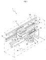
- Fig. 1 is a perspective view illustrating the schematic structure of the inkjet recording apparatus of an embodiment according to the present invention
- Fig. 2 is a sectional side view of an ink cartridge used in the inkjet recording apparatus shown in Fig. 1;
- Figs. 3A and 3B are side views of the ink cartridge and a sensor shown in Fig. 1;
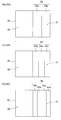
- Fig. 4A is a perspective view of an ink cartridge containing standard amount of ink of the present invention
- Fig. 4B is a partial perspective view of a variation of the ink cartridge containing standard amount
- Fig. 5A is a perspective view of an ink cartridge containing large amount of the present invention
- Fig. 5B is a partial perspective view of a variation of the ink cartridge containing large amount
- Fig. 6A is an explanatory view showing the positional relationship between an optical sensor and first and second detection target portions of an embodiment according to the present invention
- Fig. 6B is an explanatory view showing an comparative example
- Fig. 6C is an explanatory view showing an variation of the present invention wherein fist and second detection target portions are not disposed on the same plane;
- Fig. 7 is a line graph showing output voltage from the optical sensor disposed on the locations shown in Fig. 6A and 6B;
- Fig. 8 a block diagram showing the schematic structure of the electric circuit in an inkjet recording apparatus of an embodiment according to the present invention.
- Fig. 9 is a flowchart showing an overall process executed by an inkjet recording apparatus of an embodiment according to the present invention.
- Fig. 10 is a flowchart showing data obtaining process executed in the overall process shown in Fig. 9;
- Fig. 11 is a flowchart showing near-empty status determination process executed in the overall process shown in Fig. 9;
- Fig. 12 is a flowchart showing cartridge identification process which is one of the control program executed in the overall process shown in Fig. 9;
- Fig. 13 is a flowchart showing indication process for cartridge containing large amount executed in the overall process shown in Fig. 9;
- Fig. 14 is a flowchart showing indication process for cartridge containing standard amount executed in the overall process shown in Fig. 9;
- Fig. 15 is a flowchart showing indication process for near-empty status executed in the overall process shown in Fig. 9;
- Fig. 16 is a flowchart showing a cartridge scan process in order to conduct a detection on detection target portions of an ink cartridge of the present invention with a high degree of accuracy;
- Fig. 17A is a schematic diagram showing detection position in first and second detection target portions
- Figs. 17B and 17C are graphs indicating the amount of light received by the optical sensor when scanning an ink cartridge and output voltage
- Fig. 17D is a schematic diagram showing detection positions after a correction
- Fig. 18 is a flowchart showing detection position correction process executed after the cartridge scan process shown in Fig. 16;
- Fig. 19 is a flowchart showing the overall process of the inkjet recording apparatus in case detection positions are corrected
- Fig. 20 is a flowchart showing a data obtaining process in another embodiment
- Fig. 21 is an explanatory view showing detection position for ink level detection in first to third scans in another embodiment.
- Figs. 22A to 22C are enlarged views of the second detection target portion on which identification members for two, three and four bits are respectively attached.
- the inkjet recording apparatus 1 comprises a head unit 4 having a printing head 3 which is an ink head to form an image on a recording medium P such as paper, a carriage 5 mounting ink cartridges 2 and the head unit 4 thereon, a drive unit 6 which reciprocates the carriage 5 in a straight direction, a platen roller 7 extending in the direction of the reciprocating movement of the carriage 5 and facing the printing head 3, a purge unit 8 and an optical sensor 19 which serves as a detector (to be described later).
- the optical sensor 19 is fixed inside the inkjet recording apparatus 1.
- Three partitions (not shown) are disposed on a loading portion 4a of the head unit 4. Between a pair of side covers 4b formed on both sides of the loading portion 4a, the loading portion 4a is sectioned into four mounting portions by the partitions to mount ink cartridges 2.
- the drive unit 6 comprises a carriage shaft 9 extending through the lower portion of the carriage 5 parallel to the platen roller 7, a guide bar 10 extending on the upper portion of the carriage 5 parallel to the carriage shaft 9, two pulleys 11 and 12 respectively disposed above each end of the carriage 9 between the carriage shaft 9 and the guide bar 10 and an endless belt 13 extended around the two pulleys 11 and 12.
- a recording medium P is fed from a feed tray (not shown) disposed on the side or in the lower portion of the inkjet recording apparatus 1 and introduced between the printing head 3 and the platen roller 7. Subsequently, a predetermined image is formed thereon by ink being discharged from the printing head 3, and ejected outside of the inkjet recording apparatus 1.
- the purge unit 8 is disposed in one side of the platen roller 7 so as to face the printing head 3 when the head unit 4 is in a reset position.
- the purge unit 8 comprises a purge cap 14 abutting on openings of plural nozzles (not shown) of the printing head 3 to cover the openings, a pump 15, a cam 16 and an ink storage 17.
- the nozzles of the printing head 3 are covered with the purge cap 14 and deteriorated ink mixed with air bubbles accumulated inside the printing head 3 is vacuumed by the pump 15 driven by the cam 16 in order to recover the printing head 3.
- the deteriorated ink vacuumed by the pump 15 is stored in the ink storage 17.
- a wiper 20 is disposed adjacent to the purge unit 8.
- the wiper 20 is formed in the shape of a spatula.
- the wiper 20 wipes the nozzle surfaces of the printing head 3 while the carriage 5 is moving.
- a cap 18 covers the plural nozzles of the printing head 3 when the printing head 3 is back to the reset position after printing, so that ink does not get dried.
- the optical sensor 19 is disposed in the inkjet recording apparatus 1 in a manner so that light is emitted invertically to the exposure surface of the ink cartridge 2 in order to reduce noise signals (unnecessary reflected light) from an exposure surface of the ink cartridge 2.
- the inkjet recording apparatus 1 is configured to detect the ink level in the ink cartridge 2 and to identify the type of an ink cartridge 2 by comparing the amount of reflection detected by the optical sensor 19 with a threshold.
- the optical sensor 19 is disposed in the vicinity of one end of the drive unit 6, that is, in the side of the drive unit 6 wherein the platen roller 7 is disposed.
- the optical sensor 19 faces the purge unit 8 across the platen roller 7.
- the optical sensor 19 comprises a light emitter 19a and a light receiver 19b (illustrated in Fig. 3). Light emitted from the light emitter 19a to an ink cartridge 2 is received as reflected light by the light receiver 19b. Based on the amount of the reflected light received by the light receiver 19b, the ink level in the ink cartridge 2 is detected and the type of an ink cartridge 2 is identified.
- Fig. 2 is a sectional side view of one ink cartridge 2 showing the ink cartridge 2 without ink reserved therein.
- the ink cartridge 2 is formed in a box shape whose inside is almost hollow. Inside of the ink cartridge 2 is sectioned into an air chamber 43, a main ink reservoir 44 and an auxiliary ink reservoir 45 by section walls 41 and 42.
- the air chamber 43 has a space to introduce atmospheric air into the main ink reservoir 44 and communicated with atmospheric air through an air slot 47 penetrating a bottom wall 46 of the ink cartridge 2.
- the upper portion of the air chamber 43 is communicated with the main ink reservoir 44. Atmospheric air is introduced into the main ink reservoir 44 through the communicated portion of the air chamber 43.
- the main ink reservoir 44 has a sealed space in order to reserve ink and storing an ink absorbing foam (porous bodies) 48 wherein ink can be absorbed and retained.
- an ink slot 49 is formed penetrating the section wall 42.
- the main ink reservoir is communicated with the auxiliary ink reservoir 45 through the ink slot 49.
- the foam 48 is constituted with a sponge or fibrous material capable of retaining ink therein by the capillary phenomena.
- the foam 48 is compressed and stored in the main ink reservoir 44. This constitution inhibits ink from leaking out of the main ink reservoir 44 and entering air chamber 43 when, for example the ink cartridge 2 falls, and inhibits the ink entered the air chamber 43 from leaking outside of the ink cartridge 2 through the air slot 47.
- the auxiliary ink reservoir 45 reserves ink, and comprises an inclined portion 51a to which light is emitted from the optical sensor 19.
- the auxiliary ink reservoir 45 is formed in one side of the ink cartridge 2 and formed as a substantially sealed space.
- the auxiliary ink reservoir 45 is communicated with the main ink reservoir 44 through the above-mentioned ink slot 49.
- the ink reserved in the main and auxiliary ink reservoirs 44 and 45 is supplied to the printing head 3 through an ink feed opening 50 penetrating the bottom wall 46 of the ink cartridge 2.
- the inclined portion 51a is formed declining toward the main ink reservoir 44.
- a prism 52 reflection modifier
- the prism 52 is used to detect the level of the ink reserved in the ink cartridge 2 and to identify the type of the ink cartridge 2.
- the prism 52 is integrally formed on the inclined portion 51a of the side wall 51 made of optically transmittable transparent material.
- a reflector 53 facing the prism 52 with predetermined interval in between. This reflector 53 is used to change an light path transmitted the auxiliary ink reservoir 45 and formed, with predetermined angle to the prism 52, in a pouch shape having air layers in the internal space therein.
- an ink cartridge 2 configured as above, as ink is consumed by the printing head 3, depending on the amount of consumption, air is introduced into the main ink reservoir 44 from the air chamber 43, and the surface of the ink in the main ink reservoir goes down. As the ink is consumed further more and when the ink in the main ink reservoir 44 runs out, the ink in the auxiliary ink reservoir 45 is supplied to the printing head 3. When the ink in the auxiliary ink reservoir 45 is supplied, the pressure in the auxiliary ink reservoir 45 is reduced. However, as air is subsequently introduced to the auxiliary ink reservoir 45 from the air chamber 43 through the main ink reservoir 44, the air pressure reduction in the auxiliary ink reservoir 45 is eased and the ink surface in the auxiliary reservoir 45 goes down.
- the ink in the main ink reservoir 44 is firstly consumed.
- the ink in the auxiliary ink reservoir 45 is consumed after all the ink in the main ink reservoir 44 is used up.
- the ink level of the entire ink cartridge 2 can be detected by detecting the ink level in the auxiliary in reservoir 45 with using the optical sensor 19.
- Figs. 3A and 3B are side views of the ink cartridge 2 and the optical sensor 19 with cross sectional views of some part of the ink cartridge 2.
- the light emitted from the light emitter 19a of the optical sensor 19 (light path X) reflects on the boundary surface of the internal surface of the reflector 53 and the air 72, i.e. on the prism 52 (light path Y), because the refractive index of the material constituting the ink cartridge 2 and the refractive index of the air 72 in the auxiliary ink reservoir 45 are different.
- the amount of the reflected light proceeding toward the light receiver 19b of the sensor 19 from the inside of the ink cartridge 2 is larger than the amount of the reflected light when there is plenty of ink 71 is in the ink cartridge 2.
- the amount of the reflected light (light path Y) reflected from the ink cartridge 2 changes depending on the remaining amount of the ink 71. Therefore, by detecting the difference of the light amount with the light receiver 19b of the optical sensor 19, the ink level in the ink cartridge 2 can be detected.
- the above-described structure wherein the amount of the remaining ink 71 is detected by the amount of the light emitted from the light emitter 19a of the optical sensor 19 to the inside of the auxiliary ink reservoir 45 and reflected therefrom constitutes a first ink level detector.
- the status of the ink cartridge 2 being nearly empty can be detected when the ink 71 does not exist in the upper portion of the auxiliary ink reservoir 45, that is, before the ink 71 runs out from the ink cartridge 2. This is because the inclined portion 51a and the reflector 53 are disposed in the upper portion of the auxiliary ink reservoir 45.
- the light receiver 19b of the optical sensor 19 receives a large amount of reflected light as described above. The amount of remaining ink 71 at this time is reference amount (to be described later) for the near-empty status of the ink cartridge 2.
- the ink 71 is reserved in the main and the auxiliary ink reservoirs 44 and 45 of the ink cartridge 2 and supplied to the printing head 3.
- two types of ink cartridges are used. These ink cartridges initially reserve different amount of ink. To be more precise, the amount of ink 71 reserved in each auxiliary ink reservoir 45 is the same but the amount of ink 71 reserved in each main ink reservoir 44 is different. Depending on the amount of ink 71 in the main ink reservoirs 44, these two types of ink cartridges are distinguished between an ink cartridge 2A containing standard amount and an ink cartridge 2B containing large amount.
- Fig. 4A shows an ink cartridge 2A containing standard amount.
- the left half of the prism 52 is a first detection target portion 82 wherein the ink level in an ink cartridge 2 is optically detected whether or not the remaining amount of the ink 71 is more than the reference amount.
- the right half of the prism 52 formed on the inclined portion 51a of the side wall 51 is a second detection target portion 81 wherein the type of an ink cartridge 2 is optically identified.
- the optical sensor 19 can optically detect the ink level in the ink cartridge 2A whether or not the amount of the ink 71 is more than the reference amount by using the first detection target portion 82 when the optical sensor 19 is moved relative to the ink cartridge 2A and positioned at a detection position corresponding to the first detection target portion 82.
- the optical sensor 19 can optically identify the type of the ink cartridge 2A by using the second detection target portion 81 when the sensor 19 is moved relative to the ink cartridge 2A and positioned at a detection position corresponding to the second detection target portion 81.
- Fig. 4B shows a variation of the ink cartridge 2A containing standard amount.
- a projecting portion 21 is formed instead of the inclined portion 51a on the ink cartridge 2A.
- the left side of the projecting portion 21 is the first detection target portion 82 and the right side of the projecting portion 21 is the second detection target portion 81.
- a space is formed so as to communicate with the auxiliary ink reservoir 45 and ink can enter therein.
- ink also exists in the space.
- ink is consumed and the ink level in the auxiliary ink reservoir 45 becomes lower, ink does not exist in the projecting portion 21.
- the optical sensor 19 is formed almost in a "U" shape in profile.
- one of the light emitter 19a and the light receiver 19b is disposed so that one pair of the light emitter 19a and the light receiver 19b face each other. If the light emitter 19a is disposed on the upper portion 19A, the light receiver 19b is disposed on the lower portion 19B. This disposition can be vice versa.
- a detection of ink level and identification of the type of an ink cartridge 2 can be conducted, similarly to the above-described embodiment, when the projecting portion 21 of the ink cartridge 2A is moved relative to the optical sensor 19, as the arrows in Fig.
- the amount of the transmitted light is determined by three levels which is to be described in detail in the section referring to a variation of the ink cartridge 2B.
- Fig. 5A shows the ink cartridge 2B containing large amount.
- an identification memeber such as aluminum foil 80 is disposed for identification of the type of an ink cartridge 2.
- the right half of the prism 52 is the second detection target portion 81 wherein the type of an ink cartridge 2 is optically identified.
- the left half of the prism 52 is the first detection target portion 82 wherein the ink level in an ink cartridge 2 is optically detected whether or not the amount of the ink 71 is more than the reference amount.
- the aluminum foil 80 reflects light by the nature thereof when light is emitted from the light emitter 19a of the optical sensor 19 on the aluminum foil 80 disposed on the second detection target portion 81.
- the amount of reflected light reflected toward the light receiver 19b is much larger than the amount of reflected light reflected from the ink cartridge 2A on which the aluminum foil 80 is not disposed.
- the ink cartridge 2B containing large amount and the ink cartridge 2A containing standard amount can be identified.
- the appearance of the ink cartridge 2A mentioned above is the same as the appearance of the ink cartridge 2B, shown in Fig. 5A, except for the aluminum foil 80 disposed on the ink cartridge 2B.
- the identification of the ink cartridges 2A and 2B can be reliably conducted by detecting the second detection target portion 81.
- the light receiver 19b receives a large amount of reflected light because the light emitted from the light emitter 19a is reflected on the prism 52 as described above.
- the amount of the light detected from the second detection target portion 81 of the ink cartridge 2B containing large amount and the amount of light detected from the second detection target portion 81 of the ink cartridge 2A containing standard amount by the optical sensor 19 are not distinctly different. Therefore, when the amount of the remaining ink 71 is less than the reference amount, identification of an ink cartridge 2 is not conducted. It is meaningless to identify an ink cartridge when the amount of remaining ink 71 becomes less than the reference amount, although the two types of ink cartridges 2A and 2B initially contain different amount of ink 71 when they are unused.
- the left half of the prism 52 becomes the second detection target portion 81 and the right half becomes the first detection target portion 82.
- the carriage 5 is moved so that the detection position of the first detection portion 82 (on the prism 52) of the ink cartridge 2B faces the emitting direction of the light emitter 19a of the optical sensor 19. Then, light is emitted from the light emitter 19a of the optical sensor 19 to the prism 52 of the ink cartridge 2B presently mounted.
- the light receiver 19b receives the reflected light reflected on the prism 52, and ink level data is obtained depending on the difference in the amount of the reflected light and the data is stored to be determined whether or not the amount of the ink 71 in the ink cartridge 2B is equal to or more than the reference amount by a CPU 91 disposed in the inkjet recording apparatus 1 (to be described later).
- the carriage 5 is moved by a controller 90 (to be described later) disposed in the inkjet recording apparatus 1 so that the detection position of the second detection target portion 81 (the aluminum foil 80) of the ink cartridge 2B faces the emitting direction of the light emitter 19a of the optical sensor 19.
- Light is emitted from the light emitter 19a of the optical sensor 19 to the aluminum foil 80.
- Identification data is obtained from the amount of the reflected light reflected on the aluminum foil 80 and stored to be identified whether the ink cartridge 2 presently in use is the ink cartridge 2B or the ink cartridge 2A by the CPU 91 disposed in the inkjet recording apparatus 1 (to be described later).
- the constitution wherein the ink cartridge 2 presently in use is identified whether it is the ink cartridge 2B containing large amount or the ink cartridge 2A containing standard amount according to the amount of the reflected light on the prism 52 which is initially emitted from the light emitter 19a of the optical sensor 19 to the second detection target portion 81 (of the prism 52) serves as an identifier.
- FIG. 5B a variation of the ink cartridge 2B containing large amount is illustrated therein.
- a projecting portion 21 is formed instead of the inclined portion 51a on the ink cartridge 2B. From an anterior view, the right side of the projecting portion 21 is the second detection target portion 81 and the left side of the projecting portion 21 is the first detection target portion 82.
- the aluminum foil 80 (identifier) is disposed on the second detection target portion 81 positioned on the right side of the projecting portion 21 of the ink cartridge 2B.
- a space is formed so as to communicate with the auxiliary ink reservoir 45 and ink can enter therein. When there is plenty of ink in the auxiliary ink reservoir 45, ink also exists in the space. When ink is consumed and the ink level in the auxiliary ink reservoir 45 becomes lower, ink does not exist in the projecting portion 21.
- the optical sensor 19 is formed almost in a "U" shape in profile. On an upper portion 19A and a lower portion 19B of the optical sensor 19, one of the light emitter 19a and the light receiver 19b is disposed so that one pair of the light emitter 19a and the light receiver 19b face each other. If the light emitter 19a is disposed on the upper portion 19A, the light receiver 19b is disposed on the lower portion 19B. This disposition can be vice versa.
- the detection of ink level and the identification of the type of an ink cartridge 2 can be conducted, similarly to the above-described embodiment, when the projecting portion 21 of the ink cartridge 2B is moved relative to the optical sensor 19, as the arrows in Fig.
- the amount of the transmitted light is determined by three levels.
- the amount of light received by the light receiver 19b differs in the following three cases: (1) the aluminum foil 80 (identification member) is disposed, (2) the aluminum foil 80 is not disposed and there is plenty of ink 71, and (3) the aluminum foil 80 is not disposed and there isn't much ink 71 left. In the first case, the light receiver 19b does not at all receive the light emitted by the light emitter 19a.
- the light receiver 19b receives the half of the light emitted by the light emitter 19a. In the third case, the light receiver 19b receives most of the light emitted by the light emitter 19a.
- the optical sensor 19 is fixed inside the inkjet recording apparatus 1.
- the optical sensor 19 faces the first and the second detection target portions 82 and 81 of the ink cartridge 2 mounted on the carriage 5 when the carriage 5 is moved, and ink level data and identification data are obtained.
- this constitution can be arranged so that the carriage 5 mounting the ink cartridge 2B containing large amount is moved relative to the optical sensor 19 and the projecting portion 21 of the ink cartridge 2B goes through between the upper portion 19A and the lower portion 19B of the sensor 19.
- the optical sensor 19 can be configured to be movable by a mover and moves relative to the carriage 5 in stationary status so that the projecting portion 21 of the ink cartridge 2B mounted on the carriage 5 goes through between the upper portion 19A and the lower portion 19B of the optical sensor 19. In short, the projecting portion 21 should go through between the upper portion 19A and the lower portion 19B of the optical sensor 19.
- the second detection target portion 81 for identifying the type of an ink cartridge 2 is disposed on the right half of the inclined portion 51a in Fig. 5, and the first detection target portion 82 for detecting ink level in an ink cartridge 2 is disposed on the left half of the incline portion 51a. This disposition is arranged in consideration of the positions relative to the optical sensor 19.
- the first and second detection target portions 82 and 81 are aligned in relation to the angles made by optical axis of the light emitted from the optical sensor 19 as shown in Fig. 6A.
- the first detection target portion 82 for detecting ink level is disposed in the side of the acute angle ⁇ 1
- the second detection target portion 81 for identifying the type of an ink cartridge 2 is disposed in the side of the obtuse angle ⁇ 2.
- the surface, on which these detection target portions 82 and 81 are disposed can be divided into two parts: one part having the acute angle ⁇ 1 and the other having the obtuse angle ⁇ 2.
- the detection target portion 82 for remaining amount of ink is disposed on the part having the acute angle ⁇ 1 and the detection target portion 81 for cartridge information is disposed on the other part having the obtuse angle ⁇ 2.
- the second detection target portion 81 for identifying the type of an ink cartridge 2 is disposed away from the optical sensor 19, compared to the distance between the optical sensor 19 and the first detection target portion 82.
- the optical sensor 19 tends to detect the reflected light from the second detection target portion 81 falsely when the optical sensor 19 is scanning the first detection target portion 82 for detecting ink level because the second detection target portion 81 is disposed nearer to the optical sensor 19 than the first detection target portion 82.
- the light emitted from the optical sensor 19 is suitably directive, the light is diffused in the vicinity (in the direction shown with dotted lines in Figs. 6A to 6C) of the optical axis (shown in full line in Figs. 6A to 6C) to certain degree.
- the second detection target portion 81 for identifying the type of an ink cartridge 2 having high reflectance in the vicinity of the optical sensor 19 is disposed, the light reflected on the second detection target portion 81 can be detected in the areas A1 and A2 shown in the Figs. 6A and 6B.
- the reflected light in the area A1 does not enter the optical sensor 19, but the reflected light in the area A2 does.
- the optical sensor 19 consequently detects this unnecessary light.
- the optical sensor 19 is more likely to receive the light diffracted at the second detection target portion 81.
- proximity of the absolute distance between the second detection target portion 81 for identification of an ink cartridge 2 and the optical sensor 19 while the optical sensor 19 is scanning the first detection target portion 82 for detecting ink level as shown in Fig. 6B is another factor to cause a false detection of unnecessary light.
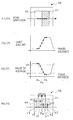
- Fig. 7 is a graph showing the result of measurements in the output voltage from the optical sensor 19 in two different cases: in case of disposing a reflective sticker 80 on the part with acute angle (referred to as acute angle side hereinafter), and on the part with obtuse angle (referred to as obtuse angle side).
- the horizontal scales of the graph indicate the relational position of the optical sensor 19 and the ink cartridge 2, and the vertical scales show the output voltage from the optical sensor 19.
- the output voltage from the optical sensor 19 is high when the optical sensor 19 is not detecting light, and low when the optical sensor 19 is detecting light.
- the reflective sticker 80 is disposed on the acute angle side (refer to the line indicated as "acute angle side” in Fig. 7)
- the optical sensor 19 initiates a scan on the reflective sticker 80 (the second detection target portion 81) corresponding to the change in the relational position of the optical sensor 19 and the ink cartridge 2
- the output voltage from the optical sensor 19 drastically drops (in the vicinity of the relational position 4 to 10 mm in the graph).
- the output voltage from the optical sensor 19 only increase up to 1.5 to 2.5 V (in the vicinity of the relational position 11 to 18 mm in the graph).
- the output voltage from the optical sensor 19 does not sufficiently increases despite of the initiation of the scan on the prism 52 (the first detection target portion 82) because the optical sensor 19 is detecting unexpected reflected light. If a determination of ink level is attempted while the S/N ratio is low based on the amount reflected light from the prism 52, with relatively high threshold (for example, around 3V), it can be falsely determined that there is significant reflected light from the prism 52 (the first detection target portion 82) and that the ink cartridge 2 is in the near-empty status although the ink 71 is still remained therein.
- the threshold could be set relatively low (for example, around 1V) so that the reflected light from the prism 52 (the first detection target portion 82) is not determined to be significant.
- the significant reflected light sent to the optical sensor 19 when the ink cartridge 2 actually becomes nearly empty might not be determined existent, i.e. the ink cartridge 2 might be falsely determined not to be in the near-empty status even while the ink 71 is not remained therein.
- the reflective sticker 80 is disposed on the obtuse angle side (refer to the line indicated as "obtuse angle side" in Fig. 7)
- the optical sensor 19 initiates a scan on the prism 52 (the first detection target portion) corresponding to the change in the relational position of the optical sensor 19 and the ink cartridge 2
- the output voltage from the optical sensor 19 is maintained very high (in the vicinity of the relational position 4 to 10 mm in the graph).
- the output voltage from the optical sensor 19 drastically drops (in the vicinity of the relational position 12 to 18 mm in the graph).
- the optical sensor 19 does not detect any unexpected reflected light while scanning the prism 52 (the first detection target portion 82) and the voltage outputted therefrom becomes sufficiently high. Under the condition where the S/N ratio is high, the existent of the significant reflected light from the prism 52 (the first detection target portion 82) and the near-empty status of the ink cartridge 2 can be correctly determined irrelevant to a slight variation in the output voltage from the optical sensor 19.
- the first detection target portion 82 for detecting ink level is set to be in a first reflection status wherein the reflectance thereof is lower than the reflectance of the second detection target portion 81 for identification when the amount of remained ink is equal to or more than predetermined amount. If the optical sensor 19 detects larger amount of light than the amount the optical sensor 19 detects in the first reflection status because of the reflected light from the second detection target portion 81, a false determination, i.e. the amount of remaining ink is determined to be less than the predetermined amount, can be made. However, the above disposition of the detection target portions 82 and 81 can inhibit a false detection caused by the reflected light from the second detection target portion 81, and the above-described false determination should not be caused.
- the first and second detection target portions 82 and 81 are aligned in the direction of the relative movement of the optical sensor 19 and the ink cartridge 2 and formed on the same surface.
- This and the above-described relational configuration of the optical sensor 19 and the first and second detection target portions 82 and 81 can effectively inhibit a detection of undesired light. It is also possible to adopt other configurations to inhibit a detection of undesired light if the first and second detection target portions 82 and 81 do not have to be formed on the same surface.
- Fig. 6C shows an example of this kind of configuration.
- the second detection target portion 81 can be disposed with certain angle so as to deflect the light emitted from the optical sensor 19, when the optical sensor 19 is scanning the first detection target portion 82, by adjusting the angle of the second detection target portion 81 with a reference to the optical axis of the light from the optical sensor 19.
- the light emitted from the optical sensor 19 is suitably directive and diffused in the vicinity (in the direction shown with dotted lines in Fig. 6C) of the optical axis (shown in full line in Fig. 6C). If the second detection target portion 81 having high reflectance in the vicinity of the optical sensor 19, the light reflected on the second detection target portion 81 is detected in the area A3 shown in Fig. 6C. By adjusting the angle of the second detection target portion 81 as shown in Fig. 6C, the area A3 can be moved away from the optical sensor 19 and a detection of unnecessary light can be inhibited.
- Fig. 8 a block diagram showing the schematic structure of the electric circuit in the inkjet recording apparatus 1.
- the controller 90 which controls the inkjet recording apparatus 1 is equipped on a circuit board of the main body of the inkjet recording apparatus 1.
- the controller 90 comprises a micro computer (CPU) 91 consisting of one chip, a ROM 92 storing control programs which the CPU 91 conducts and data for fixed values, a RAM 93 which stores various data temporarily, an EEPROM 94 which is a writable nonvolatile memory, an image memory 95 and a gate array 96.
- the EEPROM 94 comprises a first downcounter 94a, a second downcounter 94b, a FLAG 1 storage area 94c, FLAG 2 storage area 94d and FLAG 3 storage area 94e.
- near-empty flag (FLAG 1) is stored.
- the near-empty flag indicates that the ink cartridge 2 is nearly empty.
- “0” is stored in the FLAG 1 storage area 94c when the amount of the remaining ink 71 is more than the reference amount, and "1" is stored when the amount is less than the reference amount.
- cartridge replacement flag (FLAG 2) is stored. The cartridge replacement flag indicates whether or not the ink cartridge 2 is replaced. If the ink cartridge 2 is not replaced, the cartridge replacement flag indicates the type of the ink cartridge 2 presently mounted.
- the computing unit CPU 91 executes a control for detecting whether or not the ink 71 is in the ink cartridge 2.
- the CPU 91 also generates timing signals for image formation and reset signals and transfers the signals to the gate array 96 respectively.
- an operation panel 107 with which a user commands image formation a motor drive circuit 102 which drives a carriage (CR) motor 101 to move the carriage 5, a motor drive circuit 104 which drives a line feed (LF) motor 103 which feeds a recording medium P, a paper sensor 105 which detects the leading edge of a recording medium P, an origin sensor 106 which detects the original position of the carriage 5, and the sensor 19 are connected.
- the movement of each device connected to the CPU 91 is controlled by the CPU 91.
- the aforementioned ROM 92, RAM 93, EEPROM 94 and the gate array 96 are connected to the CPU 91 via an address path 98 and a data path 99.
- the following describes the first and the second downcounters 94a and 94b which serve as a second ink level detector.
- the second ink level detector having only one downcounter, i.e. the first downcounter 94a, is going to be described hereinafter.
- the first downcounter 94a is disposed in the aforementioned EEPROM 94.
- the first downcounter 94a is a memory that counts the number of jets of the ink 71 from the printing head 3. For example, the first downcounter 94a subtracts "1" at every jet.
- the subtraction number can be variable depending on the size of ink drops if the size of ink drops jetted from the printing head 3 is changeable.
- Predetermined amount of ink 71 is reserved, in the initial condition, respectively in the ink cartridges 2A and 2B.
- the maximum numbers of jetting with the amount of the ink 71 reserved in the ink cartridges 2A and 2B are respectively almost constant.
- the type of the ink cartridge 2 newly installed is identified by the optical sensor 19, and the maximum number of jetting corresponding to the amount of the ink 71 contained in the ink cartridge 2 newly installed is stored in the first downcounter 94a.
- the first downcounter 94a countdowns the number of jetting. Approximate amount of ink consumption is shown on an indicator 111 through a drive circuit 110 corresponding to the count. In this way, a user can know the approximate amount of remaining ink.
- the ink level display on the indicator 111 is changed to a display showing the near-empty status.
- the number of jetting for the reference amount on the ink 71 that is, the maximum number of jetting in the near-empty status, is set in the first downcounter 94a. In other words, a detection of the near-empty status triggers setting the number of jetting for the reference amount of the ink 71.
- the initial amount of the ink 71 reserved in the ink cartridge 2 is consumed first from the main ink reservoir 44.
- the ink 71 in the auxiliary ink reservoir 45 is used.
- the surface of the ink 71 in the auxiliary ink reservoir 45 becomes lower than the bottom of the prism 52, as shown in Fig. 3B, the light emitted from the light emitter 19a of the optical sensor 19 is reflected by the prism 52 toward the light receiver 19b of the optical sensor 19 (light path Y). This changes (increases) the amount of the reflected light detected by the light receiver 19b of the optical sensor 19.
- this change in the amount of the reflected light is recognized by the CPU 91 as the near-empty status and the corresponding near-empty flag (FLAG 1) is turned on. That is, "1" is stored in the FLAG 1 storage area of the EEPROM 94.
- the near-empty flag (FLAG 1) is turned on (the amount of ink 71 is detected to be less than the reference amount), the ink cartridge 2 is not yet actually empty. Thus image formation can be continued until the ink cartridge 2 becomes empty (the number of jetting reaches the empty threshold).
- the maximum number of jetting in the near-empty status is set in the first downcounter 94a, countdown is conducted and the countdown number nears zero, the ink cartridge 2 becomes actually empty and "Replace ink cartridge" is indicated.
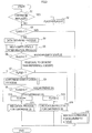
- Fig. 9 shows an overall process executed by the inkjet recording apparatus 1. This process is initiated while the power of the inkjet recording apparatus 1 is on, and either when a replacement button is pressed and opening/closing of a cover is detected or at every paper feed.
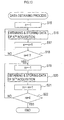
- ink level data and identification data is executed by the optical sensor 19 in accordance with the flowchart shown in Fig. 10. It is to be noted that although the ink level data and identification data are obtained respectively three times in this flowchart, it can be any odd number of times, e.g. five times or seven times. Alternatively, it can be only one time in order to make the process easier.
- the CR motor 101 is firstly driven by the carriage motor drive circuit 102 to move the carriage 5 so that the first detection target portion 82 of the ink cartridge 2 faces the emitting direction of the light emitter 19a of the optical sensor 19.
- ink level data are obtained from three positions in the first detection target portion 82 and stored in the EEPROM 94.
- For "n th " acquisition of ink level data firstly "1” is stored in “n” storage area of the RAM 93 in S15. Then the carriage 5 is moved to the predetermined detection position for "n th " data acquisition. Light is emitted from the light emitter 19a of the optical sensor 19 to the first detection target portion 82 (prism 52) of the installed ink cartridge 2.
- the light receiver 19b receives reflected light from the first detection target portion 82, converts the amount of reflected light into value of voltage and outputs the value.
- An A/D converter 19c compares the value of voltage outputted from the light receiver 19b with predetermined value and converts the value outputted from the light receiver 19b into "1" or "0". "1” is obtained when the value of voltage outputted from the light receiver 19b is higher than the predetermined value. "0” is obtained when the value of voltage outputted from the light receiver 19b is lower than the predetermined value.
- the value of voltage outputted by the light receiver 19b is high.
- the predetermined value of voltage is set to be lower than the value of high voltage outputted from the light receiver 19b. Therefore "1" is obtained for the ink level data.
- the predetermined value of voltage is set to be higher than the value of low voltage outputted from the light receiver 19b. Therefore "0” is obtained for the ink level data.
- the ink level data converted into “1” or “0” is stored in the EEPROM 94 in S16. After first acquisition of ink level data as above, "1" is added to the "n” stored in the "n” storage area in S17.
- identification data are obtained from three positions in the second detection target portion 81 and stored in the EEPROM 94.
- "m th " acquisition of identification data "1" is stored in “m” storage area of the RAM 93 in S19. Then the carriage 5 is moved to the predetermined detection position for "m th " data acquisition.
- Light is emitted from the light emitter 19a of the optical sensor 19 to the second detection target portion 81 (the aluminum foil 80 or the prism 52) of the installed ink cartridge 2.
- the light receiver 19b receives reflected light from the second detection target portion 81, converts the amount of reflected light into value of voltage and outputs the value.
- An A/D converter 19c compares the value of voltage outputted from the light receiver 19b with predetermined value and converts the value outputted from the light receiver 19b into “1” or "0". "1” is obtained when the value of voltage outputted from the light receiver 19b is higher than the predetermined value. "0” is obtained when the value of voltage outputted from the light receiver 19b is lower than the predetermined value.
- the aluminum foil 80 is not disposed on the second detection target portion 81 and there is plenty of ink 71 in the ink cartridge 2, the amount of reflected light from the second detection target portion 81 is small. The value of voltage outputted by the light receiver 19b, in this case, is high.
- the predetermined value is set to be lower than the value of high voltage outputted from the light receiver 19b. Therefore "1" is obtained for the identification data.
- the aluminum foil 80 is disposed on the second detection target portion 81 or the ink cartridge 2 is nearly empty while the aluminum foil 80 is not disposed on the second detection target portion 81, the amount of reflected light from the second detection target portion 81 is large.
- the value of voltage outputted by the light receiver 19b in this case, is low.
- the predetermined value is set to be higher than the value of low voltage outputted from the light receiver 19b. Therefore "0” is obtained for the identification data.
- the identification data converted into “1” or "0” is stored in the EEPROM 94 in S20.
- near-empty status determination process is executed in accordance with the flowchart shown in Fig. 11 to determine whether or not the ink cartridge 2 is in a near-empty status.
- the ink cartridge 2 is determined to be in a near-empty status, "1" is stored in the FLAG1 storage area 94c of the EEPROM 94 and the near-empty status determination process is terminated.
- This process of determining the near-empty status serves as a determiner.
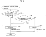
- the value of the cartridge replacement flag (FLAG 2) stored in the FLAG 2 storage area 94d of the EEPROM 94 is determined either 0, 1 or 2.
- the ink cartridge 2 newly installed after a replacement is determined to be the ink cartridge 2A containing standard amount, "1" is stored in the FLAG 3 storage area 94e of the EEPROM 94 and the cartridge identification process is terminated.
- This process of cartridge identification serves as an identifier.
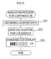
- Fig. 13 is a flowchart showing the process of the inkjet recording apparatus 1 wherein display of LCD of the indicator 111 indicates that an ink cartridge 2B containing large amount is installed in case the ink cartridge 2B is newly installed after a replacement, or in case a replacement of the ink cartridge 2 was not conducted but the ink cartridge 2 presently mounted is identified to be the ink cartridge 2B.
- the count data is obtained from the first downcounter 94a.
- the maximum number of jetting is set in the first downcounter 94a when the ink cartridge 2 is replaced with the ink cartridge 2B and the number is counted down at every jetting of the ink 71 from the nozzles of the printing head 3.
- the amount of the ink 71 in the ink cartridge 2B can be known by obtaining the count data from the first downcounter 94a.
- the CPU 91 calculates the data in S32 and changes the display of the LCD of the indicator 111 according to the result of the calculation in S33.
- S33 of Fig. 13 illustrates the ink cartridge 2B not yet in the near-empty status and about 30% of the ink 71 remained therein. It goes without saying that when the ink cartridge 2B is newly installed after a replacement, the maximum number of jetting for the full amount is set in the first downcoutner 94a and the LCD displays that the amount of the remaining ink 71 is 100%. Moreover, the LCD of the indicator 111 displays "LG (large)" since the value "1" is stored in the FLAG 2 (the cartridge identification flag) storage area 94d in the EEPROM 94. From this display, a user can know that an ink cartridge 2B is presently installed. After the display of the LCD is changed in S33, the operation of the inkjet recording apparatus 1 of the present embodiment shown in Fig. 9 is completed.
- Fig. 14 is a flowchart showing the process of the inkjet recording apparatus 1 wherein LCD display of the indicator 111 indicates that an ink cartridge 2A containing standard amount is installed in case the ink cartridge 2A is newly installed after a replacement, or in case a replacement of the ink cartridge 2 was not conducted but the ink cartridge 2 presently installed is identified to be the ink cartridge 2A.
- the count data is obtained from the first downcounter 94a in S34.
- the maximum number of jetting is set in the first downcounter 94a when the ink cartridge 2 is replaced with the ink cartridge 2A and the number is counted down at every jetting of the ink 71 from the nozzles of the printing head 3.
- the amount of the ink 71 in the ink cartridge 2A can be known by obtaining the count data from the first downcounter 94a.
- the CPU 91 calculates the data in S35 and changes the LCD display of the indicator 111 in S36.
- the maximum number of jetting is 80,000 and the count presently obtained is 24,000, for example, the amount of the remaining ink 71 is 30% of the initial amount.
- S36 of Fig. 14 illustrates the ink cartridge 2A not yet in the near-empty status and about 30% of the ink 71 remained therein. It also goes without saying that when the ink cartridge 2A is newly installed after a replacement, the maximum number of jetting for the full amount is sent in the first downcoutner 94a and the LCD displays that the amount of the remaining ink 71 is 100%. Moreover, the LCD of the indicator 111 displays "NM (normal)" as the value "2" is stored in the FLAG 2 (the cartridge replacement flag) storage area 94d in the EEPROM 94. From this display, a user can know that the ink cartridge 2A is presently installed. After the display of the LCD is changed in S36, the operation of the inkjet recording apparatus 1 of the present embodiment shown in Fig. 9 is completed.
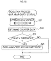
- the display of the LCD of the indicator 111 is firstly changed to the near-empty status indication in S47. Specifically, the LCD display is changed to show that about 10% of the ink 71 is remained. Moreover, the LCD of the indicator 111 displays "NE (near-empty)" as the value "1" is stored in the FLAG 1 storage area 94c in the EEPROM 94. From this display, a user can know that the ink cartridge 2 is in a near-empty status. Subsequently, the count data is obtained from the first downcounter 94a in S38.
- the maximum number of jetting in the near-empty status is set in the first downcounter 94a when the ink cartridge 2 is determined to be in a near-empty status for the first time (S6: NO), and the number is counted down at every jetting of the ink 71 from the nozzles of the printing head 3.
- the amount of the ink 71 in the ink cartridge 2 can be known by obtaining the count data from the first downcounter 94a.
- the display on the LCD of the indicator 111 is changed to indicate that the ink cartridge 2 needs to be replaced in S40, and then this process is completed. To the contrary, if the count obtained from the first downcounter 94a is larger than the predetermined value (S39:NO), this process is completed without taking any further steps.
- a correction process can be done to avoid detections at inappropriate positions according to the following.
- the detection position correction process is described in below with a reference to Figs. 16 to 19.
- the cartridge scan process in Fig. 16 is initiated when the cartridge replacement button is pressed and an opening/closing of the cover is detected while the power of the inkjet recording apparatus 1 is on. That is to say, this process is initiated when the ink cartridge 2 is replaced.
- the CR motor 101 is driven by the CR motor drive circuit and the carriage 5 is moved (is started to move) until the first detection target portion 82 faces the emitting direction of the light emitter 19a of the optical sensor 19.
- light amount data are obtained and stored seven times as described in detail later. This number can be, needless to say, less or more than seven times.
- An encoder (not shown) is disposed in the CR motor 101 and the CPU 91 specifies the position of the optical sensor 19 based on signals outputted from this encoder.
- the CPU 91 stands by until the carriage 5 is moved to a predetermined detection position for "x th " data acquisition (S120:NO).
- the carriage 5 is moved to the detection position for "x th " acquisition (S120:YES)
- light is emitted from the light emitter 19a of the optical sensor 19 to (the first and second detection target portions 82 and 81 of) the ink cartridge 2 and a value of voltage V0 (the value of voltage becomes smaller when there is more amount of light, in the present embodiment) which indicates the amount of the light received by the light receiver 19b from the ink cartridge 2 is stored in the EEPROM 94 as light amount data in S130.
- a coordinate value P (the value which becomes greater in the left side of the horizontal coordinate axis in Fig. 17A in the present embodiment) which indicates the detection position for "x th " data acquisition is stored so that the coordinate value P can be specified.
- Fig. 17B shows a graph wherein the vertical scales indicate the amount of light (light intensity) according to light amount data obtained from the first to seventh data acquisitions as above, and the horizontal scales indicate the travel distance of the optical sensor 19 in relation to the ink cartridge 2.
- the graph shown in Fig. 17C has vertical scales indicating values of voltage V0 and horizontal scales indicating the travel distance.
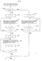
- the value of voltage V0 checked in the previous step is determined whether or not it is larger than a predetermined upper limit Vh.
- the upper limit Vh is determined to be smaller by predetermined value of voltage than the value of voltage indicating the amount of the reflected light expected to be received by the light receiver 19b when the light emitted from the light emitter 19a of the optical sensor 19 in the above cartridge scan process does not reflect on the ink cartridge 2.
- the value of voltage V0 indicated in the light amount data obtained from "y th " data acquisition is not larger than the upper limit Vh (S230:NO)
- the lower limit V1 is predetermined to be larger by predetermined value of voltage than the value of voltage indicating the amount of the reflected light expected to be received by the light receiver 19b when light emitted from the light emitter 19a of the optical sensor 19 in the cartridge scan process reflects on the ink cartridge 2.
- the optical sensor 19 scans the ink cartridge 2
- the optical sensor 19 moves to conduct a detection on the first detection target portion 82 and then on the second detection target portion 81.
- the detection position correction process is to be conducted on the premise that the ink cartridge 2 has been replaced.
- the light receiver 19b does not receive the reflected light from the first detection target portion 82 when the optical sensor 19 scans the ink cartridge 2.
- the reflected light from the first detection portion 82 is received by the light receiver 19b.
- all the light amount data stored in the EEPROM 94 show smaller value of voltage than the lower limit V1, and the process does not proceed from S230 to S240.
- the initial value "0" remains unchanged in the "A" storage area.
- a cartridge replacement can be checked to assure an appropriate replacement of the ink cartridge 2.
- the location of the boundary between the first and second detection target portions 82 and 81 is calculated.
- identification detection positions k1 to k3 at which the optical sensor 19 receives the reflected light from the second detection target portion 81, and remaining amount detection positions r1 to r3 at which the optical sensor 19 received the reflected light from the first detection target portion 82 are corrected.
- Both of the identification detection positions k1 to k3 and the ink level detection positions r1 to r3 are predetermined parameters used in a process which is going to be described later.
- the second identification detection position k2 is located at predetermined distance k0 away from the boundary location to the right direction.
- the third identification detection position k3 is located at the half of the predetermined distance k0 away from k2 to the right direction.
- the first identification detection position k1 is located at the half of the predetermined distance k0 away from k2 to the left direction.
- the predetermined distance k0 corresponds to the half of the width (the horizontal length) of the second detection target portion 81.
- the position at the predetermined distance k0 away from the boundary position to the right direction is the center of the second detection target portion 81. Therefore, the reception of the reflected light from the second detection target portion 81 on the identification detection positions k1 to k3 is assured.
- the second ink level detection position r2 is located at predetermined distance r0 away from the boundary position to the left direction.
- the third ink level detection position r3 is located at the half of the predetermined distance r0 away from r3 in the left direction.
- a first ink level detection position is located at the half of the predetermined distance r0 away from r2 in the right direction.
- the predetermined distance r0 corresponds to the half of the width (the horizontal length) of the first detection target portion 82.
- the position at the predetermined distance r0 away from the boundary location to the left direction is the center of the first detection target portion 82. Therefore, the reception of the reflected light from the first detection target portion 82 on ink level detection positions 82 on ink level detection positions r1 to r3 is assured.
- the identification detection position k1 to k3 constitute second detection positions.
- the ink level detection positions r1 to r3 constitute first detection positions.
- the light amount data stored in the EEPROM 94 all contain values of voltage V0 greater than the lower limit V1 only when the light receiver 19b does not receive the reflection light from both of the first and second detection target portions 82 and 81 during a scan in the ink cartridge 2 conducted by the optical sensor 19.
- the ink cartridge 2 going through a scan is identified to be an ink cartridge 2A wherein a second detection target portion 81 is not disposed.
- the type of the ink cartridge 2 is also checked.
- the process shown in Fig. 19 is initiated at every paper feed while the power of the inkjet recording apparatus 1 is on.
- ink level data and identification data is conducted by using the optical sensor 19. This process is carried out according to the flowchart shown in Fig. 10.
- the number of data acquisition can be three or any odd number larger than three.
- the constitution can be arranged to have only one time for obtaining ink level data and identification data respectively in order to simplify the process.
- the CR motor 101 is firstly driven by the carriage motor drive circuit 102 to move the carriage 5 so that the first detection target portion 82 of the ink cartridge 2 faces the emitting direction of the light emitter 19a of the optical sensor 19.
- ink level data are obtained from three positions in the first detection target portion 82 and stored in the EEPROM 94.
- For "n th " acquisition of ink level data firstly "1” is stored in “n” storage area of the RAM 93 in S15. Then the carriage 5 is moved to the predetermined detection position rm (refer to Fig. 17D) for "n th " data acquisition.
- Light is emitted from the light emitter 19a of the optical sensor 19 to the first detection target portion 82 (prism 52) of the installed ink cartridge 2.
- the light receiver 19b receives reflected light from the first detection target portion 82, converts the amount of reflected light into a value of voltage and outputs the value.
- An A/D converter 19c compares the value of voltage outputted from the light receiver 19b with predetermined value and converts the value outputted from the light receiver 19b into "1" or "0".
- the ink level data converted into "1” or "0” is stored in the EEPROM 94 in S16. As described earlier, when there is plenty of ink 71 in the ink cartridge 2, the amount of reflected light from the first detection target portion 82 is small.
- the value of voltage outputted by the light receiver 19b is high.
- the predetermined value of voltage is set to be lower than the value of high voltage outputted from the light receiver 19b. Therefore "1" is obtained for the ink level data.
- the predetermined value of voltage is set to be higher than the value of low voltage outputted from the light receiver 19b. Therefore "0” is obtained for the ink level data.
- identification data are obtained from three positions in the second detection target portion 81 and stored in the EEPROM 94.
- "m th " acquisition of identification data "1" is stored in “m” storage area of the RAM 93 in S19. Then the carriage 5 is moved to the predetermined detection position km (refer to Fig. 17D) for "m th " data acquisition.
- Light is emitted from the light emitter 19a of the optical sensor 19 to the second detection target portion 81 (the aluminum foil 80 or the prism 52) of the installed ink cartridge 2.
- the light receiver 19b receives reflected light from the second detection target portion 81, converters the amount of reflected light into a value of voltage and outputs the value.
- An A/D converter 19c compares the value of voltage outputted from the light receiver 19b with predetermined value of voltage and converts the value of voltage outputted from the light receiver 19b into “1” or “0".
- the identification data converted into “1” or “0” is stored in the EEPROM 94 in S20.
- the aluminum foil 80 is not disposed on the second detection target portion 81 and there is plenty of ink 71 in the ink cartridge 2, the amount of reflected light from the second detection target portion 81 is small.
- the value of voltage outputted by the light receiver 19b, in this case, is high. Therefore "1" is obtained for the identification data.
- detection positions for detecting ink level r1 to r3 and detection positions for identification k1 to k3 can be corrected in the detection position correction process in Fig. 18 based on detection results obtained in the cartridge scan process in Fig. 16. Consequently, error detections of the optical sensor 19 on inappropriate positions can be prevented without setting the detection positions on the first and second detection target portions 82 and 81 accurately or disposing the first and second detection target portions 82 and 81 accurately, even if the area used as a first detection target portion 82 is narrower than a conventional constitution wherein a second detection target portion 81 is not disposed.
- This constitution reduce the amount of time and work necessary for setting the detection position on the first and second detection target portions 82 and 81 accurately and disposing the first and second detection target portions 82 and 81 accurately. Thus the total cost of the inkjet recording apparatus 1 or the ink cartridge 2 can be reduced.
- FLAG 3 a value, either "0” or "1" is stored (S310, S340) based on the amount of light received by the light receiver 19b of the optical sensor 19 in the detection position correction process in Fig. 18. It may be said that the type of an ink cartridge 2 is identified in Fig. 19 based on the amount of light received by the light receiver 19b of the optical sensor 19.
- the boundary area of the first and second detection target portion 82 and 81 can be specified based on the position of the optical sensor 19 when the amount of light received by the light receiver 19b changes significantly (i.e. the value of voltage V0 that indicates the amount of light changes from the upper limit Vh to the lower limit Vl) while the optical sensor 19 is scanning the first and second detection target portions 82 and 81, that is, the position where the light emitted from the light emitter 19a reflects for the first time.
- the detection positions spaced from the position of the boundary in the side of the second detection target portion 81 are corrected to be identification detection positions k1 to k3, and the detection position spaced from the position of the boundary in the side of the first detection target portion 82 are corrected to be ink level detection positions r1 to r3.
- This correction can inhibit more assuredly the optical sensor 19 from detecting reflected light in a wrong detection target portion.
- the ink level data in the form of "1" or "0" is stored in the EEPROM 94.
- the above-mentioned detection position for "q th " data acquisition is a detection position used if the ink cartridge 2 is identified to be an ink cartridge 2A.
- both of the first and second detection target portions 82 and 81 newly constitute a first detection target portion 82 as shown in Fig. 21. Almost on the center of the entire width of the new first detection target portion 82, ink level detection positions for the first to third data acquisitions (q1 to q3) disposed evenly thereon are newly set.
- the three ink level detection positions previously set corresponding to the coordinate value Pc can be corrected to be the ink level detection positions for the first to third data acquisitions (q1 to q3). That is, based on the position difference between the center position and the coordinate value Pc, the rest of the two positions in both sides are corrected.
- "1" is added to "q” stored in the "q” storage area.
- the second ink level detector has only one downcounter, i.e. the first downcounter 94a.
- the following explains a variation of the second ink level detector having two downcounters, i.e. the first and second downcounters 94a and 94b.
- the maximum number of jetting is set in the first down counter 94a depending on the type of the ink cartridge 2 newly installed.
- the number of jetting for reference amount is set in the second downcounter 94b. Every time the ink 71 is jetted, the count only on the first downcounter 94a is decremented. (The count on the second downcounter 94b does not change.)
- the ink level indication indicated by the indicator 111 is changed based on the count on the first downcounter 94a.
- the ink level indication indicated by the indicator 111 is continued to be changed based on the count on the first downcounter 94a.
- the near-empty status detection triggers the count initiation on the second downcounter 94b.
- the second downcounter 94b becomes a reference to confirm whether or not the ink cartridge 2 is actually in a near-empty status when the power of the inkjet recording apparatus 1 is turned on/off. If the count of the second downcounter 94b is smaller than the number of jetting for reference amount, the ink cartridge 2 is actually a near-empty status. If the count remains unchanged from the jetting number for the reference amount, the ink cartridge 2 is not yet in a near-empty status.
- the reference amount is set to be equal to the amount of the ink 71 in a near-empty status.
- This reference amount can be changed to about 50 to 40% of the initial amount on the ink 71 by changing the sizes of the main and auxiliary ink reservoirs 44 and 45.
- the first downcounter 94a is reset, i.e. the maximum number of jetting for the reference amount of ink 71 is set therein when the amount of the ink 71 becomes less than the reference amount, in case the second ink level detector has only first downcounter 94a.
- a user can foresee the timing when the ink 71 runs out compared to the constitution wherein the count is continued until the amount of the ink 71 becomes the amount in a near-empty status.
- the second detection target portion 81 of the ink cartridge 2 is configured with the aluminum foil (identifying member) 80 disposed thereon so that the entire portion of the half of the prism 52 becomes reflective.
- an identifying member 83 for 2 bits data can be disposed as shown in Fig. 22A.
- an identifying member 84 for 3 bits data can be disposed as shown in Fig. 22B.
- an identifying member 85 for 4 bits data can be disposed as shown in Fig. 22C.
- identification data can be detected with plural bits, e.g. 2, 3 or 4 bits, and more than two types, e.g. four, eight or sixteen types of ink cartridges can be identified.
- more kinds of ink cartridges can be identified if an identifying member is divided into more areas, there is a limit to the number of areas because difference in voltage output from the optical sensor 19 becomes smaller as areas become narrower.
- the number of detection in each area conducted by the optical sensor 19 does not necessarily have to be three times, but can be reduced to two or even one time when the dimension of each area becomes small.
- identification data in 2 bits should be able to identify each cartridge because up to four types of ink cartridges can be identified by identification data in 2 bits. If there are ink cartridges containing large and standard amount of ink respectively for yellow, magenta, cyan and black colors, these eight types of ink cartridges can be all identified by identification data in 3 bits. It should be possible to identify more types of ink cartridges, if there are more colors available, by identification data in 4 bits in the present situation.
- each area of the second detection target portion 81 can be constituted with light-transmissive and reflective portions and the arrangements shown in Figs. 22A to 22C.
- the first downcounter 94a or the first and the second downcounters 94a and 94b are used as the second ink level detector.
- one or two upcounter/s can be used. If only one upcounter is used, the upcounter should be reset to "0" when an unused ink cartridge 2 is installed. Appropriate thresholds can be adopted depending on each type of ink cartridge 2 so that the amount of remaining ink can be indicated.
- the near-empty status is detected by the first ink level detector, the ink level display of the indicator 111 is changed to a near-empty status display, the upcounter is reset to "0" and another threshold can be adopted for a reference when the ink of the reference amount runs out.
- a display of "replace ink cartridge” can be indicated. If two upcounters are used, both the first and the second upcounters are reset to be “0" when an unused ink cartridge is installed. At every jet of ink, only the count on the first upcounter is incremented, but not the count on the second upcounter.
- Appropriate threshold can be adopted in the first upcounter for ink level indication according to the type of the ink cartridge 2. The ink level indication displayed on the indicator 111 is changed based on the count on the first upcounter.
- the first ink level detector When the near-empty status of the ink cartridge 2 is detected by the first ink level detector, certain number of jetting to jet out reference amount of ink is set on the first upcounter corresponding to the type of mounted ink cartridge 2, and counting up on the second upcounter is initiated.
- the ink level indication displayed on the indicator 111 is continued corresponding to the count on the first upcounter. Indication of "replace ink cartridge" can be displayed when the count on the second upcounter goes beyond the threshold at which the ink is supposed to run out.
- aluminum foil is used as an identifying member in the above-described embodiment
- other reflective material e.g. silver paper
- the identifying member can be disposed on the ink cartridge 2A containing standard amount of ink, instead of on the ink cartridge 2B containing large amount. All such modifications are intended to be included within the scope of this invention.
Abstract
Description
- This invention relates to an ink cartridge used for image forming apparatus such as a printer, a copier and a facsimile. This invention also relates to a detection device for identification of an ink cartridge, and to an image forming apparatus comprising the ink cartridge and the detection device.
- Amongst conventional ink cartridges used for an inkjet recording apparatus, some of them are constituted to allow ink level detection by optical devices.
- Generally, ink of this type of ink cartridge is reserved in a case having an optically transparent portion. Light is emitted from a light source to inside the case through the transparent portion. The amount of reflected light changes depending whether or not ink is remained in the ink cartridge. The presence of ink is detected by this system. Yoshiyama et al (Japanese Patent Publication No. 2002-292890), for example, discloses this type of ink cartridge.
- In an ink level detection device for this type of ink cartridge, when there is plenty of ink reserved in an auxiliary ink reservoir of an ink cartridge, light emitted from a light emitter enters inside the ink cartridge, because the refractive index of the material constituting the ink cartridge and the refractive index of the ink are very close. Then the light is reflected toward a direction different from the direction toward a light receiver by a reflector disposed in the ink cartridge. Thus the amount of reflected light toward the light receiver is small.
- When ink is not in the auxiliary ink reservoir, the light emitted from the light emitter is reflected between inside of an outer wall of the auxiliary ink reservoir and air (i.e. at a prism). The amount reflected light toward the light receiver, in this case, is large. As described above, the amount of reflected light from an ink cartridge changes depending whether or not ink is reserved therein, and the presence of ink is detected from the difference in the light amount by using a light receiver.
- Recently, the consumption of ink has been increasing as more image formation is conducted by users on larger quantity of recording media. Ink cartridges containing large amount of ink have been on demand as a replacement for ink cartridges containing standard amount of ink, which is presently available. However, such type of ink cartridges are not yet attained and not supplied to the market.
- From above reason, a device which can identify an ink cartridge containing standard amount and an ink cartridge containing larger amount were not in need, therefore, did not exist.
- However, if ink cartridges containing large amount of ink should be provided to the market in order to meet the need of users, distinct identification of an ink cartridge containing standard amount and an ink cartridge containing large amount is required to be conducted. An error detection of ink amount can cause a failure in image formation due to a shortage of ink.
- It is an object of the present invention to provide an ink cartridge for an inkjet recording apparatus with a detection device, having a portion which optically facilitates detection of the ink level in an ink cartridge and a portion which optically facilitates identification of the type of an ink cartridge. These portions make detection of ink level and identification of the type of an ink cartridge by a detection device possible. Error detection of ink level and failure in image formation can be inhibited by this kind of ink cartridge.
- It is another object of the present invention to provide a detection device which can conduct identification of the type of an ink cartridge installed in an image formation apparatus as well as detection of ink level so as to inhibit a failure in image formation. It is still another object of the present invention to provide an image formation apparatus having this kind of detection device.
- To attain these and other objects, the ink cartridge of the present invention is detachably installed in an image formation apparatus having a detection device, and able to reserve ink in a case. The ink cartridge comprises a first detection target portion wherein ink level in the case can be optically detected by the detection device, and a second detection target portion wherein the type of the ink cartridge can be identified by the detection device, both disposed on the case thereof.
- According to the ink cartridge of the present invention, a first detection target portion for detecting ink level and a second detection target portion for identifying the type of an ink cartridge are disposed on the case, and detection of ink level and identification of the type of an ink cartridge can be efficiently conducted by one detection device. Error detection of ink level can be inhibited by this constitution, and hence failure of image formation can be prevented.
- The first detection target portion for ink level detection and the second detection target portion for cartridge identification of the ink cartridge of the present invention are preferably aligned.
- Consequently, ink level detection and cartridge identification can be conducted simply by moving the detection device in the direction of the alignment of the first and second detection target portions in relation to the ink cartridge, and changing detection position.
- The first and second detection target portions of the above ink cartridge are preferably formed on the same surface of the case.
- The above disposition of the first and second detection target portions can simplify the structure of an ink cartridge.
- The first detection target portion for ink level detection preferably includes a reflection modifier wherein the state of reflection of light emitted from outside the case changes depending on the ink level in the case.
- Accordingly, the detection device can easily detect the ink level in an ink cartridge by detecting the state of the reflected light from the first detection target portion.
- Moreover, the case of the ink cartridge preferably comprises a first reflector having a flat portion unparallel to the surface where the first and second detection target portions are formed. When light is emitted in predetermined direction from outside the case to the reflection modifier, if the amount of remaining ink in the case is equal to or more than predetermined amount, the light can enter the case from the reflection modifier, and can be reflected at the first reflector to a direction opposite to a predetermined direction. If the amount of remaining ink in the case is less than the predetermined amount, the light can be reflected at the reflection modifier to the predetermined direction.
- With the above constitution, the detection device detects small amount of reflected light, if the amount of remaining ink in the case is more than the predetermined amount, and detects large amount of reflected light, if the amount of remaining ink in the case is less than the predetermined amount. Therefore the detection device can detect the ink level in an ink cartridge very easily.
- The second detection target portion for cartridge identification preferably comprises a second reflector wherein the state of reflection is constant irrelevant to the ink level of an ink cartridge.
- The state of reflection is constant if the second reflector is disposed on the second detection target portion, but inconstant without the second reflector. Consequently, the type of an ink cartridge can be easily identified.
- The reflectance of the second reflector is preferably higher than the reflectance of the reflection modifier in the state when the amount of remaining ink in the case is less than the predetermined amount.
- Because of the higher reflectance of the second reflector, the detection device can easily detect the ink level in the ink cartridge and easily identify the type of the ink cartridge.
- A reflective member of the above second reflector is preferably disposed on the surface of an ink cartridge.
- Due to the reflective member of the second reflector disposed on the surface of the ink cartridge, the same type of case can be used for different types of ink cartridges initially containing different amount of ink. The cost for making various types of cases corresponding to the number of the type of ink cartridges, therefore, can be cut down.
- The reflection modifier of the ink cartridge described above preferably includes a prism. The reflection modifier can be formed simultaneously with the case by injection molding.
- The second detection target portion for cartridge identification described above is preferably able to set the state of reflection in at least two areas.
- With above constitution, three or more types of ink cartridges can be identified.
- The detection device of the present invention is disposed in an image formation apparatus having a mounting portion that allows installation of an ink cartridge, and detects the ink level of an ink cartridge mounted on the mounting portion by using detection target portions disposed on the ink cartridge. Plural types of ink cartridges containing different initial amount of ink in the same color can be installed on the mounting portion. The detection target portions of the ink cartridge are constituted with first and second detection target portions. From the first detection target portion, it can be detected whether or not the amount of ink in the ink cartridge is equal to or more than reference amount. The reference amount is set to be less than the initial amount reserved in an ink cartridge containing the least of all the plural types of the ink cartridges. From the second detection target portion, the type of an ink cartridge can be identified. The detection device comprises a detector, a transporter, a determiner and an identifier. The detector optically detects the type of an ink cartridge installed on the mounting portion and whether or not the amount of ink in the ink cartridge is equal to or more than the reference amount by using the first and second detection target portions of the installed ink cartridge. The transporter moves detection position of the detector relative to the first and second detection target portions of the ink cartridge. The determiner determines whether or not the amount of ink in the ink cartridge installed on the mounting portion is equal to or more than the reference amount based on the result of an optical detection in the first detection target portion of the ink cartridge conducted by the detector at a first detection position which is a corresponding position to detect the first detection target portion. The identifier identifies the type of the ink cartridge installed on the mounting portion based on the result of an optical detection in the second detection target portion of the ink cartridge conducted by the detector at a second detection position which is a corresponding position to detect the second detection target portion.
- According to the above-described detection device, both ink level detection and identification of the type of an ink cartridge installed on the mounting portion can be conducted with the simple structure of the detection device. Any type of ink cartridge amongst those containing different amount of ink therein can be identified, and a user can be aware of the type of the ink cartridge presently in use. The number of recording medium possible to from images thereon can be estimated. Therefore, failure in image formation caused by a shortage of ink in the middle of image formation can be inhibited.
- The detector of the detection device preferably comprises a light emitter which emits light toward the detection target portions of the ink cartridge, and a light receiver which receives light reflected from the detection target portions. The identifier and the determiner of the detection device can identify the type of the ink cartridge and detect ink level based on the amount of light received by the light receiver.
- With the detection device constituted as above, cartridge identification and ink level detection can be conducted based on the amount of light received by the light receiver, that is, data by which the determination process can be easily conducted.
- Furthermore, the light receiver of the detector in the detection device preferably receives light emitted from the light emitter and reflected on the detection target portions.
- Still furthermore, the detector of the detection device preferably conducts detection at plural detection positions for detecting both the first and second detection target portions.
- The above-described detection device can prevent error detection of ink level in each detection target portion, and detect the ink level more accurately, in comparison with a detector of a detection device which conducts detection at only one detection position each for detecting the first and second detection target portions.
- The identifier of the detection device preferably does not identify the type of an ink cartridge if the determiner determines that the amount of remaining ink in the ink cartridge is less than the reference amount. This system can simplify the process.
- The detector of the detection device can store light reception signals outputted from the light receiver when the position of the light emitted from the light emitter is changed from the first detection target portion to second detection target portion into a memory storage as light reception data. The identifier and determiner can conduct identification and ink level detection based on the light reception data stored in the memory storage.
- By the above-described constitution, data storage into the memory storage and data determination are conducted separately since light reception signals of the first and second detection target portions disposed on the ink cartridge is stored as light reception data into the memory storage by the detector, and cartridge identification and ink level detection are conducted base on the stored light reception data by the identifier and the determiner. This constitution can make it possible to conduct a cartridge identification and ink level detection with the light reception data stored in the memory storage even if, for example, power cut occurs, or the image forming apparatus is switched off and restarted for some purpose in the middle of image formation.
- The image formation apparatus of the present invention comprises a first ink level detector having the above-described detection device, and a second ink level detector which detects ink level based on the amount of image formation on recording media that has been conducted since the installation of the ink cartridge on the mounting portion. When an ink cartridge is installed on the mounting portion, the second ink level detector immediately sets the initial ink level of the ink cartridge in unused condition based on the type of the ink cartridge identified by the first ink level detector. Subsequently, the second ink level detector updates the ink level corresponding to the number of inkjets from the ink head. When the first ink level detector determines that the amount of ink in the ink cartridge has become less than the reference amount, the second ink level detector sets the ink level to a predetermined level corresponding to the reference amount. Then, the second ink level detector updates the ink level based on the number of inkjets from the ink head.
- According to the image formation apparatus described above, a change in the initial ink level due to a change in the type of ink cartridge is reflected in display of the detection result. When the ink level is determined to be less than the level of the reference amount, ink level based on the initial ink level and the amount of image formation is set to the predetermined level corresponding to the reference amount, and updated according to the amount of ink actually jetted out from the ink head. Hence, ink level can be confirmed based on the amount of ink actually consumed, even if the amount of ink jetted out from the ink head in one time changes because of an environmental change, such as temperature. Accurate ink level detection can be conducted irrelevant to the environment.
- The image formation apparatus preferably has a corrector which corrects at least the first detection position in relation to the ink cartridge installed on the mounting portion based on the result of detection at the first and second detection positions respectively corresponding to the first and second detection target portions.
- The image formation apparatus constituted as above can correct the detection position/s (only the first detection position, or both of the first and second detection positions) based on the result of detection by the detector at the first and second detection positions.
- Because a correction of detection positions is possible, it is not necessary to set the first and second detection positions precisely or arrange the detection target portions accurately, even if each area used for respective detection target portion is narrower than the area in the conventional structure wherein the second detection target portion is not disposed. Yet, error detection, e.g. the detector detects on a wrong detection target portion, can be inhibited.
- For the above-described constitution, the time and work required to set and arrange the detection positions and the detection target portions accurately can be reduced. As a result, the manufacturing cost of the image formation apparatus or the ink cartridge can be cut down.
- The corrector preferably sets a new boundary between the first and second detection positions, and corrects the first and second detection position based on the new boundary, if the amount of the light received by the light receiver of the detector changes more greatly than a predetermined level while the detector is moved by the transporter relatively so as to pass through the area including at least the first and second detection positions.
- According to the image formation apparatus constituted as above, the following detection of one or both of the first and second detection target portion/s can be conducted more accurately.
- One of the possible procedures of correction conducted by the corrector described above can be as follows: a position spaced out from the new boundary set as above for predetermined distance in a first direction which is the passage direction of the detector when the detector passes through the area including the first and second detection positions, is corrected as the first detection position; and a position spaced out from the boundary for predetermined distance in a second direction, which is the opposite direction to the first direction, is corrected as the second detection position.
- In the image formation apparatus constituted as above, a position spaced out from the preset boundary for the predetermined distance in the first direction, which is along the passage direction, is set to be the first detection position, and a position spaced out from the preset boundary for the predetermined distance in the second direction opposite to the first direction is set to be the second detection position. By setting the predetermined distance from the preset boundary shorter than the width (the length along the passage direction) of the first detection target portion, the detector can detect the first detection target portion without failure. Moreover, by setting the predetermined distance from the preset boundary shorter than the width of the second detection target portion, the detector can detect the second detection target portion without fail.
- The corrector can be arrange to set the first and second detection target portions as a new first detection target portion and correct the first detection position, if the amount of the light received by the light receiver of the detector does not change more greatly than the predetermined level, while the detector is moved by the transporter relatively so as to pass through the area including at least the first and second detection positions. This arrangement can enlarge the area of the first detection target portion, and correct the first detection position in a wider area for reliable detection. Thus, ink level detection can be more accurately conducted.
- The present invention also provides an ink cartridge check program. This is a program for a computer system to conduct respective process for the determiner, identifier and corrector of the above-described image formation apparatus.
- The above ink cartridge check program is constituted with sequences of commands respectively arranged to be suitable for computer processing. The check program is provided, for example, via a recording media, such as FD, CD-ROM or memory card, or communication network, such as Internet, to an image formation apparatus having this program installed therein, a computer system, or a user who uses the image formation apparatus and the computer system. In order to execute this ink cartridge check program, a computer system installed in an image formation apparatus, or a computer system connected via communication path with or without wire to a printer and capable of data communication, for example, can be used.
- The present invention furthermore provides a correction method for detection positions. This correction method can be adopted to an image formation apparatus which comprises: a mounting portion capable of mounting an ink cartridge having a first detection target portion for determining whether or not the amount of the ink reserved in the ink cartridge is equal to or more than a reference amount, and a second detection target portion for identifying the type of the ink cartridge; and a detector optically capable of detecting the ink level in the ink cartridge and identifying the type of the ink cartridge by using the first and second detection target portions of the ink cartridge installed on the mounting portion, and which detects the ink level in the ink cartridge based on the result of detection in the first detection target portion and identifies the type of the ink cartridge installed on the mounting portion based on the result of detection in the second detection target portion. The detector of this kind of image forming apparatus is moved relative to the ink cartridge, and conducts detection at a first detection position predetermined to be able to detect the first detection target portion of the ink cartridge and at a second detection position predetermined to be able to detect the second detection target portion of the ink cartridge. Based on the result of the detection, at least one of the first and second detection positions relative to the ink cartridge installed on the mounting portion is/are corrected in this method.
- The invention will now be described below, by way of example, with reference to the accompanying drawings.
- Fig. 1 is a perspective view illustrating the schematic structure of the inkjet recording apparatus of an embodiment according to the present invention;
- Fig. 2 is a sectional side view of an ink cartridge used in the inkjet recording apparatus shown in Fig. 1;
- Figs. 3A and 3B are side views of the ink cartridge and a sensor shown in Fig. 1;
- Fig. 4A is a perspective view of an ink cartridge containing standard amount of ink of the present invention, and Fig. 4B is a partial perspective view of a variation of the ink cartridge containing standard amount;
- Fig. 5A is a perspective view of an ink cartridge containing large amount of the present invention, and Fig. 5B is a partial perspective view of a variation of the ink cartridge containing large amount;
- Fig. 6A is an explanatory view showing the positional relationship between an optical sensor and first and second detection target portions of an embodiment according to the present invention, Fig. 6B is an explanatory view showing an comparative example, and Fig. 6C is an explanatory view showing an variation of the present invention wherein fist and second detection target portions are not disposed on the same plane;
- Fig. 7 is a line graph showing output voltage from the optical sensor disposed on the locations shown in Fig. 6A and 6B;
- Fig. 8 a block diagram showing the schematic structure of the electric circuit in an inkjet recording apparatus of an embodiment according to the present invention;
- Fig. 9 is a flowchart showing an overall process executed by an inkjet recording apparatus of an embodiment according to the present invention;
- Fig. 10 is a flowchart showing data obtaining process executed in the overall process shown in Fig. 9;
- Fig. 11 is a flowchart showing near-empty status determination process executed in the overall process shown in Fig. 9;
- Fig. 12 is a flowchart showing cartridge identification process which is one of the control program executed in the overall process shown in Fig. 9;
- Fig. 13 is a flowchart showing indication process for cartridge containing large amount executed in the overall process shown in Fig. 9;
- Fig. 14 is a flowchart showing indication process for cartridge containing standard amount executed in the overall process shown in Fig. 9;
- Fig. 15 is a flowchart showing indication process for near-empty status executed in the overall process shown in Fig. 9;
- Fig. 16 is a flowchart showing a cartridge scan process in order to conduct a detection on detection target portions of an ink cartridge of the present invention with a high degree of accuracy;
- Fig. 17A is a schematic diagram showing detection position in first and second detection target portions, Figs. 17B and 17C are graphs indicating the amount of light received by the optical sensor when scanning an ink cartridge and output voltage, and Fig. 17D is a schematic diagram showing detection positions after a correction;
- Fig. 18 is a flowchart showing detection position correction process executed after the cartridge scan process shown in Fig. 16;
- Fig. 19 is a flowchart showing the overall process of the inkjet recording apparatus in case detection positions are corrected;
- Fig. 20 is a flowchart showing a data obtaining process in another embodiment;
- Fig. 21 is an explanatory view showing detection position for ink level detection in first to third scans in another embodiment; and
- Figs. 22A to 22C are enlarged views of the second detection target portion on which identification members for two, three and four bits are respectively attached.
- The following describes an inkjet recording apparatus as an example of an image forming apparatus.
- Referring to Fig. 1, the
inkjet recording apparatus 1 comprises ahead unit 4 having aprinting head 3 which is an ink head to form an image on a recording medium P such as paper, acarriage 5 mountingink cartridges 2 and thehead unit 4 thereon, adrive unit 6 which reciprocates thecarriage 5 in a straight direction, aplaten roller 7 extending in the direction of the reciprocating movement of thecarriage 5 and facing theprinting head 3, apurge unit 8 and anoptical sensor 19 which serves as a detector (to be described later). In the present embodiment, theoptical sensor 19 is fixed inside theinkjet recording apparatus 1. Three partitions (not shown) are disposed on aloading portion 4a of thehead unit 4. Between a pair of side covers 4b formed on both sides of theloading portion 4a, theloading portion 4a is sectioned into four mounting portions by the partitions to mountink cartridges 2. - The
drive unit 6 comprises acarriage shaft 9 extending through the lower portion of thecarriage 5 parallel to theplaten roller 7, aguide bar 10 extending on the upper portion of thecarriage 5 parallel to thecarriage shaft 9, twopulleys carriage 9 between thecarriage shaft 9 and theguide bar 10 and anendless belt 13 extended around the twopulleys - When the
pulley 11 is driven to rotate by acarriage motor 101 in the clockwise or the counterclockwise direction, corresponding to the rotational direction of thepulley 11, thecarriage 5 attached to theendless belt 13 is reciprocated straight along with thecarriage shaft 9 and theguide bar 10. - A recording medium P is fed from a feed tray (not shown) disposed on the side or in the lower portion of the
inkjet recording apparatus 1 and introduced between theprinting head 3 and theplaten roller 7. Subsequently, a predetermined image is formed thereon by ink being discharged from theprinting head 3, and ejected outside of theinkjet recording apparatus 1. - The
purge unit 8 is disposed in one side of theplaten roller 7 so as to face theprinting head 3 when thehead unit 4 is in a reset position. Thepurge unit 8 comprises apurge cap 14 abutting on openings of plural nozzles (not shown) of theprinting head 3 to cover the openings, apump 15, acam 16 and anink storage 17. When thehead unit 4 is in the reset position, the nozzles of theprinting head 3 are covered with thepurge cap 14 and deteriorated ink mixed with air bubbles accumulated inside theprinting head 3 is vacuumed by thepump 15 driven by thecam 16 in order to recover theprinting head 3. The deteriorated ink vacuumed by thepump 15 is stored in theink storage 17. - In one side of the
purge unit 8 wherein theplaten roller 7 is disposed, awiper 20 is disposed adjacent to thepurge unit 8. Thewiper 20 is formed in the shape of a spatula. Thewiper 20 wipes the nozzle surfaces of theprinting head 3 while thecarriage 5 is moving. Acap 18 covers the plural nozzles of theprinting head 3 when theprinting head 3 is back to the reset position after printing, so that ink does not get dried. - The
optical sensor 19 is disposed in theinkjet recording apparatus 1 in a manner so that light is emitted invertically to the exposure surface of theink cartridge 2 in order to reduce noise signals (unnecessary reflected light) from an exposure surface of theink cartridge 2. Theinkjet recording apparatus 1 is configured to detect the ink level in theink cartridge 2 and to identify the type of anink cartridge 2 by comparing the amount of reflection detected by theoptical sensor 19 with a threshold. - To be more particular, the
optical sensor 19 is disposed in the vicinity of one end of thedrive unit 6, that is, in the side of thedrive unit 6 wherein theplaten roller 7 is disposed. Theoptical sensor 19 faces thepurge unit 8 across theplaten roller 7. Theoptical sensor 19 comprises alight emitter 19a and alight receiver 19b (illustrated in Fig. 3). Light emitted from thelight emitter 19a to anink cartridge 2 is received as reflected light by thelight receiver 19b. Based on the amount of the reflected light received by thelight receiver 19b, the ink level in theink cartridge 2 is detected and the type of anink cartridge 2 is identified. - The followings describe the internal structure of the
ink cartridge 2 with a reference to Fig. 2. Fig. 2 is a sectional side view of oneink cartridge 2 showing theink cartridge 2 without ink reserved therein. - The
ink cartridge 2 is formed in a box shape whose inside is almost hollow. Inside of theink cartridge 2 is sectioned into anair chamber 43, amain ink reservoir 44 and anauxiliary ink reservoir 45 bysection walls air chamber 43 has a space to introduce atmospheric air into themain ink reservoir 44 and communicated with atmospheric air through anair slot 47 penetrating abottom wall 46 of theink cartridge 2. The upper portion of theair chamber 43 is communicated with themain ink reservoir 44. Atmospheric air is introduced into themain ink reservoir 44 through the communicated portion of theair chamber 43. - The
main ink reservoir 44 has a sealed space in order to reserve ink and storing an ink absorbing foam (porous bodies) 48 wherein ink can be absorbed and retained. In the lower portion of themain ink reservoir 44, anink slot 49 is formed penetrating thesection wall 42. The main ink reservoir is communicated with theauxiliary ink reservoir 45 through theink slot 49. Thefoam 48 is constituted with a sponge or fibrous material capable of retaining ink therein by the capillary phenomena. Thefoam 48 is compressed and stored in themain ink reservoir 44. This constitution inhibits ink from leaking out of themain ink reservoir 44 and enteringair chamber 43 when, for example theink cartridge 2 falls, and inhibits the ink entered theair chamber 43 from leaking outside of theink cartridge 2 through theair slot 47. - The
auxiliary ink reservoir 45 reserves ink, and comprises aninclined portion 51a to which light is emitted from theoptical sensor 19. Theauxiliary ink reservoir 45 is formed in one side of theink cartridge 2 and formed as a substantially sealed space. Theauxiliary ink reservoir 45 is communicated with themain ink reservoir 44 through the above-mentionedink slot 49. The ink reserved in the main andauxiliary ink reservoirs printing head 3 through anink feed opening 50 penetrating thebottom wall 46 of theink cartridge 2. - On the
side wall 51 of theauxiliary ink reservoir 45, theinclined portion 51a is formed declining toward themain ink reservoir 44. Inside of the inclined portion (in the side of the main ink reservoir 44), a prism 52 (reflection modifier) is formed as a detection target portion which is to be described later. Theprism 52 is used to detect the level of the ink reserved in theink cartridge 2 and to identify the type of theink cartridge 2. Theprism 52 is integrally formed on theinclined portion 51a of theside wall 51 made of optically transmittable transparent material. In the upper portion of theauxiliary ink reservoir 45, there is areflector 53 facing theprism 52 with predetermined interval in between. Thisreflector 53 is used to change an light path transmitted theauxiliary ink reservoir 45 and formed, with predetermined angle to theprism 52, in a pouch shape having air layers in the internal space therein. - According to an
ink cartridge 2 configured as above, as ink is consumed by theprinting head 3, depending on the amount of consumption, air is introduced into themain ink reservoir 44 from theair chamber 43, and the surface of the ink in the main ink reservoir goes down. As the ink is consumed further more and when the ink in themain ink reservoir 44 runs out, the ink in theauxiliary ink reservoir 45 is supplied to theprinting head 3. When the ink in theauxiliary ink reservoir 45 is supplied, the pressure in theauxiliary ink reservoir 45 is reduced. However, as air is subsequently introduced to theauxiliary ink reservoir 45 from theair chamber 43 through themain ink reservoir 44, the air pressure reduction in theauxiliary ink reservoir 45 is eased and the ink surface in theauxiliary reservoir 45 goes down. - In the
ink cartridge 2, the ink in themain ink reservoir 44 is firstly consumed. The ink in theauxiliary ink reservoir 45 is consumed after all the ink in themain ink reservoir 44 is used up. Hence, the ink level of theentire ink cartridge 2 can be detected by detecting the ink level in the auxiliary inreservoir 45 with using theoptical sensor 19. - The following describes the principle of the ink level detection with a reference to Figs. 3A and 3B. Figs. 3A and 3B are side views of the
ink cartridge 2 and theoptical sensor 19 with cross sectional views of some part of theink cartridge 2. - When there is plenty of
ink 71 in theink cartridge 2, as shown in Fig. 3A, light emitted from thelight emitter 19a of the optical sensor 19 (light path X) transmits theink 71 and proceeds in theink cartridge 2 because the refractive index of the material forming theink cartridge 2 and the refractive index of theink 71 are extremely close. The light subsequently reaches thereflector 53 disposed in theauxiliary ink reservoir 45. Since the index of the material constituting thereflector 53 and the index ofair 72 in thereflector 53 are different, the light reached thereflector 53 reflects on the boundary surface of the internal surface of thereflector 53 and the air 72 (light path Y). - On the other hand, when only small amount of the
ink 71 remains in theauxiliary ink reservoir 45 in theink cartridge 2, i.e. when the surface of theink 71 is lower than the position of theprism 52 as shown in Fig. 3B, the light emitted from thelight emitter 19a of the optical sensor 19 (light path X) reflects on the boundary surface of the internal surface of thereflector 53 and theair 72, i.e. on the prism 52 (light path Y), because the refractive index of the material constituting theink cartridge 2 and the refractive index of theair 72 in theauxiliary ink reservoir 45 are different. Thus, the amount of the reflected light proceeding toward thelight receiver 19b of thesensor 19 from the inside of theink cartridge 2 is larger than the amount of the reflected light when there is plenty ofink 71 is in theink cartridge 2. - As described above, the amount of the reflected light (light path Y) reflected from the
ink cartridge 2 changes depending on the remaining amount of theink 71. Therefore, by detecting the difference of the light amount with thelight receiver 19b of theoptical sensor 19, the ink level in theink cartridge 2 can be detected. - The above-described structure wherein the amount of the remaining
ink 71 is detected by the amount of the light emitted from thelight emitter 19a of theoptical sensor 19 to the inside of theauxiliary ink reservoir 45 and reflected therefrom constitutes a first ink level detector. - The status of the
ink cartridge 2 being nearly empty (near-empty status) can be detected when theink 71 does not exist in the upper portion of theauxiliary ink reservoir 45, that is, before theink 71 runs out from theink cartridge 2. This is because theinclined portion 51a and thereflector 53 are disposed in the upper portion of theauxiliary ink reservoir 45. When the surface of theink 71 becomes lower than the position of theprism 52, thelight receiver 19b of theoptical sensor 19 receives a large amount of reflected light as described above. The amount of remainingink 71 at this time is reference amount (to be described later) for the near-empty status of theink cartridge 2. - As described above, the
ink 71 is reserved in the main and theauxiliary ink reservoirs ink cartridge 2 and supplied to theprinting head 3. In the present embodiment, two types of ink cartridges are used. These ink cartridges initially reserve different amount of ink. To be more precise, the amount ofink 71 reserved in eachauxiliary ink reservoir 45 is the same but the amount ofink 71 reserved in eachmain ink reservoir 44 is different. Depending on the amount ofink 71 in themain ink reservoirs 44, these two types of ink cartridges are distinguished between anink cartridge 2A containing standard amount and anink cartridge 2B containing large amount. Only the difference between theseink cartridges ink 71 reserved in themain ink reservoirs 44. The size and the shape of these ink cartridges are exactly the same and theink cartridges - Fig. 4A shows an
ink cartridge 2A containing standard amount. The left half of theprism 52 is a firstdetection target portion 82 wherein the ink level in anink cartridge 2 is optically detected whether or not the remaining amount of theink 71 is more than the reference amount. The right half of theprism 52 formed on theinclined portion 51a of theside wall 51 is a seconddetection target portion 81 wherein the type of anink cartridge 2 is optically identified. - The
optical sensor 19 can optically detect the ink level in theink cartridge 2A whether or not the amount of theink 71 is more than the reference amount by using the firstdetection target portion 82 when theoptical sensor 19 is moved relative to theink cartridge 2A and positioned at a detection position corresponding to the firstdetection target portion 82. Theoptical sensor 19 can optically identify the type of theink cartridge 2A by using the seconddetection target portion 81 when thesensor 19 is moved relative to theink cartridge 2A and positioned at a detection position corresponding to the seconddetection target portion 81. - If there is plenty of
ink 71 in theink cartridge 2A, light emitted from thelight emitter 19a of theoptical sensor 19 to the first and the seconddetection target portions ink 71, proceeds in theink cartridge 2A, and the light path thereof is changed by thereflector 53. Hence, the amount of the reflected light reflected toward thelight receiver 19b becomes small. - Fig. 4B shows a variation of the
ink cartridge 2A containing standard amount. - In this variation, a projecting
portion 21 is formed instead of theinclined portion 51a on theink cartridge 2A. In an anterior view, the left side of the projectingportion 21 is the firstdetection target portion 82 and the right side of the projectingportion 21 is the seconddetection target portion 81. In the projectingportion 21, a space is formed so as to communicate with theauxiliary ink reservoir 45 and ink can enter therein. When there is plenty of ink in theauxiliary ink reservoir 45, ink also exists in the space. When ink is consumed and the ink level in theauxiliary ink reservoir 45 becomes lower, ink does not exist in the projectingportion 21. - In this variation, the
optical sensor 19 is formed almost in a "U" shape in profile. On anupper portion 19A and alower portion 19B of theoptical sensor 19, one of thelight emitter 19a and thelight receiver 19b is disposed so that one pair of thelight emitter 19a and thelight receiver 19b face each other. If thelight emitter 19a is disposed on theupper portion 19A, thelight receiver 19b is disposed on thelower portion 19B. This disposition can be vice versa. A detection of ink level and identification of the type of anink cartridge 2 can be conducted, similarly to the above-described embodiment, when the projectingportion 21 of theink cartridge 2A is moved relative to theoptical sensor 19, as the arrows in Fig. 4B show, between theupper portion 19A and thelower portion 19B of theoptical sensor 19, and thesensor 19 detects the amount of the transmitted light in the first and seconddetection target portions ink cartridge 2B. - Fig. 5A shows the
ink cartridge 2B containing large amount. On the right half of theprism 52 formed on theinclined portion 51a of theside wall 51, an identification memeber such asaluminum foil 80 is disposed for identification of the type of anink cartridge 2. The right half of theprism 52 is the seconddetection target portion 81 wherein the type of anink cartridge 2 is optically identified. The left half of theprism 52 is the firstdetection target portion 82 wherein the ink level in anink cartridge 2 is optically detected whether or not the amount of theink 71 is more than the reference amount. - The
aluminum foil 80 reflects light by the nature thereof when light is emitted from thelight emitter 19a of theoptical sensor 19 on thealuminum foil 80 disposed on the seconddetection target portion 81. The amount of reflected light reflected toward thelight receiver 19b is much larger than the amount of reflected light reflected from theink cartridge 2A on which thealuminum foil 80 is not disposed. By the difference in the amount of reflected light, theink cartridge 2B containing large amount and theink cartridge 2A containing standard amount can be identified. The appearance of theink cartridge 2A mentioned above is the same as the appearance of theink cartridge 2B, shown in Fig. 5A, except for thealuminum foil 80 disposed on theink cartridge 2B. - When there is plenty of
ink 71 reserved in theink cartridge 2A containing standard amount, as explained above, the light emitted from thelight emitter 19a of theoptical sensor 19 is barely received by thelight receiver 19b. Thus, the identification of theink cartridges detection target portion 81. However, when the amount of remainingink 71 in theink cartridge 2A is less than the reference amount (theink cartridge 2A is in the near-empty status), thelight receiver 19b receives a large amount of reflected light because the light emitted from thelight emitter 19a is reflected on theprism 52 as described above. Accordingly, the amount of the light detected from the seconddetection target portion 81 of theink cartridge 2B containing large amount and the amount of light detected from the seconddetection target portion 81 of theink cartridge 2A containing standard amount by theoptical sensor 19 are not distinctly different. Therefore, when the amount of the remainingink 71 is less than the reference amount, identification of anink cartridge 2 is not conducted. It is meaningless to identify an ink cartridge when the amount of remainingink 71 becomes less than the reference amount, although the two types ofink cartridges ink 71 when they are unused. - It is to be noted that if the
aluminum foil 80 is disposed on the left half of theprism 52, the left half of theprism 52 becomes the seconddetection target portion 81 and the right half becomes the firstdetection target portion 82. - The
carriage 5 is moved so that the detection position of the first detection portion 82 (on the prism 52) of theink cartridge 2B faces the emitting direction of thelight emitter 19a of theoptical sensor 19. Then, light is emitted from thelight emitter 19a of theoptical sensor 19 to theprism 52 of theink cartridge 2B presently mounted. Thelight receiver 19b receives the reflected light reflected on theprism 52, and ink level data is obtained depending on the difference in the amount of the reflected light and the data is stored to be determined whether or not the amount of theink 71 in theink cartridge 2B is equal to or more than the reference amount by aCPU 91 disposed in the inkjet recording apparatus 1 (to be described later). - Subsequently, the
carriage 5 is moved by a controller 90 (to be described later) disposed in theinkjet recording apparatus 1 so that the detection position of the second detection target portion 81 (the aluminum foil 80) of theink cartridge 2B faces the emitting direction of thelight emitter 19a of theoptical sensor 19. Light is emitted from thelight emitter 19a of theoptical sensor 19 to thealuminum foil 80. Identification data is obtained from the amount of the reflected light reflected on thealuminum foil 80 and stored to be identified whether theink cartridge 2 presently in use is theink cartridge 2B or theink cartridge 2A by theCPU 91 disposed in the inkjet recording apparatus 1 (to be described later). - The above constitution wherein the amount of the remaining
ink 71 in a mountedink cartridge 2 is determined whether or not to be equal to or more than the reference amount according to the amount of the reflected light on theprism 52 which is initially emitted from thelight emitter 19a to the first detection target portion 82 (of the prism 52) serves as a determiner. Moreover, the constitution wherein theink cartridge 2 presently in use is identified whether it is theink cartridge 2B containing large amount or theink cartridge 2A containing standard amount according to the amount of the reflected light on theprism 52 which is initially emitted from thelight emitter 19a of theoptical sensor 19 to the second detection target portion 81 (of the prism 52) serves as an identifier. - It is also possible to conduct the detection of the amount of the reflected light by moving the
sensor 19 with a mover while thecarriage 5 remains stationary. - Referring now to Fig. 5B, a variation of the
ink cartridge 2B containing large amount is illustrated therein. - In this variation, a projecting
portion 21 is formed instead of theinclined portion 51a on theink cartridge 2B. From an anterior view, the right side of the projectingportion 21 is the seconddetection target portion 81 and the left side of the projectingportion 21 is the firstdetection target portion 82. The aluminum foil 80 (identifier) is disposed on the seconddetection target portion 81 positioned on the right side of the projectingportion 21 of theink cartridge 2B. In the projectingportion 21, a space is formed so as to communicate with theauxiliary ink reservoir 45 and ink can enter therein. When there is plenty of ink in theauxiliary ink reservoir 45, ink also exists in the space. When ink is consumed and the ink level in theauxiliary ink reservoir 45 becomes lower, ink does not exist in the projectingportion 21. - The
optical sensor 19 is formed almost in a "U" shape in profile. On anupper portion 19A and alower portion 19B of theoptical sensor 19, one of thelight emitter 19a and thelight receiver 19b is disposed so that one pair of thelight emitter 19a and thelight receiver 19b face each other. If thelight emitter 19a is disposed on theupper portion 19A, thelight receiver 19b is disposed on thelower portion 19B. This disposition can be vice versa. The detection of ink level and the identification of the type of anink cartridge 2 can be conducted, similarly to the above-described embodiment, when the projectingportion 21 of theink cartridge 2B is moved relative to theoptical sensor 19, as the arrows in Fig. 5B show, between theupper portion 19A and thelower portion 19B of theoptical sensor 19 and theoptical sensor 19 detects the amount of the transmitted light in the first and seconddetection target portions light receiver 19b differs in the following three cases: (1) the aluminum foil 80 (identification member) is disposed, (2) thealuminum foil 80 is not disposed and there is plenty ofink 71, and (3) thealuminum foil 80 is not disposed and there isn'tmuch ink 71 left. In the first case, thelight receiver 19b does not at all receive the light emitted by thelight emitter 19a. In the second case, thelight receiver 19b receives the half of the light emitted by thelight emitter 19a. In the third case, thelight receiver 19b receives most of the light emitted by thelight emitter 19a. By determining the level of amount of the light received by thelight receiver 19b from these three levels, the detection of the ink level and the identification of anink cartridge 2 can be conducted similarly to the above-described embodiment. - In the present embodiment described above, the
optical sensor 19 is fixed inside theinkjet recording apparatus 1. Theoptical sensor 19 faces the first and the seconddetection target portions ink cartridge 2 mounted on thecarriage 5 when thecarriage 5 is moved, and ink level data and identification data are obtained. Alternatively, this constitution can be arranged so that thecarriage 5 mounting theink cartridge 2B containing large amount is moved relative to theoptical sensor 19 and the projectingportion 21 of theink cartridge 2B goes through between theupper portion 19A and thelower portion 19B of thesensor 19. Or theoptical sensor 19 can be configured to be movable by a mover and moves relative to thecarriage 5 in stationary status so that the projectingportion 21 of theink cartridge 2B mounted on thecarriage 5 goes through between theupper portion 19A and thelower portion 19B of theoptical sensor 19. In short, the projectingportion 21 should go through between theupper portion 19A and thelower portion 19B of theoptical sensor 19. - The above describes that the second
detection target portion 81 for identifying the type of anink cartridge 2 is disposed on the right half of theinclined portion 51a in Fig. 5, and the firstdetection target portion 82 for detecting ink level in anink cartridge 2 is disposed on the left half of theincline portion 51a. This disposition is arranged in consideration of the positions relative to theoptical sensor 19. - To be more precise, in this
inkjet recording apparatus 1, the first and seconddetection target portions optical sensor 19 as shown in Fig. 6A. The firstdetection target portion 82 for detecting ink level is disposed in the side of the acute angle 1, and the seconddetection target portion 81 for identifying the type of anink cartridge 2 is disposed in the side of the obtuse angle 2. - Since the light from the
optical sensor 19 is emitted obliquely to the first and seconddetection target portions detection target portions detection target portion 82 for remaining amount of ink is disposed on the part having the acute angle 1 and thedetection target portion 81 for cartridge information is disposed on the other part having the obtuse angle 2. - In other words, when the
optical sensor 19 is scanning the firstdetection target portion 82 for detecting ink level, the seconddetection target portion 81 for identifying the type of anink cartridge 2 is disposed away from theoptical sensor 19, compared to the distance between theoptical sensor 19 and the firstdetection target portion 82. - With this configuration of the first and second
detection target portions detection target portion 81 by theoptical sensor 19 does not occur while theoptical sensor 19 is scanning the firstdetection target portion 82 for detecting ink level. This can inhibit theoptical sensor 19 from detecting unnecessary light. - If the second
detection target portion 81 for identifying the type of anink cartridge 2 is disposed on the part having the acute angle 1 and the firstdetection target portion 82 for detecting ink level is disposed on the part having the obtuse angle 2 as shown in Fig. 6B, theoptical sensor 19 tends to detect the reflected light from the seconddetection target portion 81 falsely when theoptical sensor 19 is scanning the firstdetection target portion 82 for detecting ink level because the seconddetection target portion 81 is disposed nearer to theoptical sensor 19 than the firstdetection target portion 82. - Although the light emitted from the
optical sensor 19 is suitably directive, the light is diffused in the vicinity (in the direction shown with dotted lines in Figs. 6A to 6C) of the optical axis (shown in full line in Figs. 6A to 6C) to certain degree. If the seconddetection target portion 81 for identifying the type of anink cartridge 2 having high reflectance in the vicinity of theoptical sensor 19 is disposed, the light reflected on the seconddetection target portion 81 can be detected in the areas A1 and A2 shown in the Figs. 6A and 6B. The reflected light in the area A1 does not enter theoptical sensor 19, but the reflected light in the area A2 does. Theoptical sensor 19 consequently detects this unnecessary light. Nearer the seconddetection target portion 81 for identifying the type of anink cartridge 2 is disposed, theoptical sensor 19 is more likely to receive the light diffracted at the seconddetection target portion 81. Hence, proximity of the absolute distance between the seconddetection target portion 81 for identification of anink cartridge 2 and theoptical sensor 19 while theoptical sensor 19 is scanning the firstdetection target portion 82 for detecting ink level as shown in Fig. 6B is another factor to cause a false detection of unnecessary light. - Fig. 7 is a graph showing the result of measurements in the output voltage from the
optical sensor 19 in two different cases: in case of disposing areflective sticker 80 on the part with acute angle (referred to as acute angle side hereinafter), and on the part with obtuse angle (referred to as obtuse angle side). The horizontal scales of the graph indicate the relational position of theoptical sensor 19 and theink cartridge 2, and the vertical scales show the output voltage from theoptical sensor 19. The output voltage from theoptical sensor 19 is high when theoptical sensor 19 is not detecting light, and low when theoptical sensor 19 is detecting light. - In case the
reflective sticker 80 is disposed on the acute angle side (refer to the line indicated as "acute angle side" in Fig. 7), when theoptical sensor 19 initiates a scan on the reflective sticker 80 (the second detection target portion 81) corresponding to the change in the relational position of theoptical sensor 19 and theink cartridge 2, the output voltage from theoptical sensor 19 drastically drops (in the vicinity of therelational position 4 to 10 mm in the graph). However, when theoptical sensor 19 finishes the scan on the reflective sticker 80 (the second detection target portion 81) and subsequently initiates a scan on the prism 52 (the first detection target portion 82), the output voltage from theoptical sensor 19 only increase up to 1.5 to 2.5 V (in the vicinity of therelational position 11 to 18 mm in the graph). This indicates that the output voltage from theoptical sensor 19 does not sufficiently increases despite of the initiation of the scan on the prism 52 (the first detection target portion 82) because theoptical sensor 19 is detecting unexpected reflected light. If a determination of ink level is attempted while the S/N ratio is low based on the amount reflected light from theprism 52, with relatively high threshold (for example, around 3V), it can be falsely determined that there is significant reflected light from the prism 52 (the first detection target portion 82) and that theink cartridge 2 is in the near-empty status although theink 71 is still remained therein. The threshold could be set relatively low (for example, around 1V) so that the reflected light from the prism 52 (the first detection target portion 82) is not determined to be significant. But, in this case, the significant reflected light sent to theoptical sensor 19 when theink cartridge 2 actually becomes nearly empty might not be determined existent, i.e. theink cartridge 2 might be falsely determined not to be in the near-empty status even while theink 71 is not remained therein. - To the contrary, in case the
reflective sticker 80 is disposed on the obtuse angle side (refer to the line indicated as "obtuse angle side" in Fig. 7), when theoptical sensor 19 initiates a scan on the prism 52 (the first detection target portion) corresponding to the change in the relational position of theoptical sensor 19 and theink cartridge 2, the output voltage from theoptical sensor 19 is maintained very high (in the vicinity of therelational position 4 to 10 mm in the graph). After theoptical sensor 19 finishes the scan on the prism 52 (the first detection target portion 82) and subsequently initiates a scan on the reflective sticker 80 (the second detection target portion 81), the output voltage from theoptical sensor 19 drastically drops (in the vicinity of therelational position 12 to 18 mm in the graph). That is, theoptical sensor 19 does not detect any unexpected reflected light while scanning the prism 52 (the first detection target portion 82) and the voltage outputted therefrom becomes sufficiently high. Under the condition where the S/N ratio is high, the existent of the significant reflected light from the prism 52 (the first detection target portion 82) and the near-empty status of theink cartridge 2 can be correctly determined irrelevant to a slight variation in the output voltage from theoptical sensor 19. - In this
inkjet recording apparatus 1, the firstdetection target portion 82 for detecting ink level is set to be in a first reflection status wherein the reflectance thereof is lower than the reflectance of the seconddetection target portion 81 for identification when the amount of remained ink is equal to or more than predetermined amount. If theoptical sensor 19 detects larger amount of light than the amount theoptical sensor 19 detects in the first reflection status because of the reflected light from the seconddetection target portion 81, a false determination, i.e. the amount of remaining ink is determined to be less than the predetermined amount, can be made. However, the above disposition of thedetection target portions detection target portion 81, and the above-described false determination should not be caused. - In the examples given in Figs. 6A and 6B, the first and second
detection target portions optical sensor 19 and theink cartridge 2 and formed on the same surface. This and the above-described relational configuration of theoptical sensor 19 and the first and seconddetection target portions detection target portions - Fig. 6C shows an example of this kind of configuration. The second
detection target portion 81 can be disposed with certain angle so as to deflect the light emitted from theoptical sensor 19, when theoptical sensor 19 is scanning the firstdetection target portion 82, by adjusting the angle of the seconddetection target portion 81 with a reference to the optical axis of the light from theoptical sensor 19. - As described above, the light emitted from the
optical sensor 19 is suitably directive and diffused in the vicinity (in the direction shown with dotted lines in Fig. 6C) of the optical axis (shown in full line in Fig. 6C). If the seconddetection target portion 81 having high reflectance in the vicinity of theoptical sensor 19, the light reflected on the seconddetection target portion 81 is detected in the area A3 shown in Fig. 6C. By adjusting the angle of the seconddetection target portion 81 as shown in Fig. 6C, the area A3 can be moved away from theoptical sensor 19 and a detection of unnecessary light can be inhibited. - Followings describe the structure of the electric circuit in the
inkjet recording apparatus 1 with reference to Fig. 8. Fig. 8 a block diagram showing the schematic structure of the electric circuit in theinkjet recording apparatus 1. - The
controller 90 which controls theinkjet recording apparatus 1 is equipped on a circuit board of the main body of theinkjet recording apparatus 1. Thecontroller 90 comprises a micro computer (CPU) 91 consisting of one chip, aROM 92 storing control programs which theCPU 91 conducts and data for fixed values, aRAM 93 which stores various data temporarily, anEEPROM 94 which is a writable nonvolatile memory, animage memory 95 and agate array 96. TheEEPROM 94 comprises afirst downcounter 94a, asecond downcounter 94b, aFLAG 1storage area 94c,FLAG 2storage area 94d andFLAG 3storage area 94e. - In the
FLAG 1storage area 94c, near-empty flag (FLAG 1) is stored. The near-empty flag indicates that theink cartridge 2 is nearly empty. "0" is stored in theFLAG 1storage area 94c when the amount of the remainingink 71 is more than the reference amount, and "1" is stored when the amount is less than the reference amount. In theFLAG 2 storage area 95d, cartridge replacement flag (FLAG 2) is stored. The cartridge replacement flag indicates whether or not theink cartridge 2 is replaced. If theink cartridge 2 is not replaced, the cartridge replacement flag indicates the type of theink cartridge 2 presently mounted. "0" is stored in theFLAG 2storage area 94d when theink cartridge 2 is replaced, "1" is stored when theink cartridge 2 is not replaced and theink cartridge 2B containing large amount is presently mounted, and "2" is stored when theink cartridge 2 is not replaced and theink cartridge 2A containing standard amount is presently mounted. In theFLAG 3storage area 94e, cartridge identification flag (FLAG 3) is stored. The cartridge identification flag indicates the type of theink cartridge 2 presently mounted. "0" is stored in theFLAG 3storage area 94e when theink cartridge 2B containing large amount is presently mounted, and "1" is stored when theink cartridge 2A containing standard amount is presently mounted. - According to the control programs stored in the
ROM 92 in advance, thecomputing unit CPU 91 executes a control for detecting whether or not theink 71 is in theink cartridge 2. TheCPU 91 also generates timing signals for image formation and reset signals and transfers the signals to thegate array 96 respectively. To theCPU 91, anoperation panel 107 with which a user commands image formation, a motor drive circuit 102 which drives a carriage (CR) motor 101 to move thecarriage 5, a motor drive circuit 104 which drives a line feed (LF)motor 103 which feeds a recording medium P, apaper sensor 105 which detects the leading edge of a recording medium P, anorigin sensor 106 which detects the original position of thecarriage 5, and thesensor 19 are connected. The movement of each device connected to theCPU 91 is controlled by theCPU 91. Theaforementioned ROM 92,RAM 93,EEPROM 94 and thegate array 96 are connected to theCPU 91 via anaddress path 98 and adata path 99. - The following describes the first and the
second downcounters - Firstly, the second ink level detector having only one downcounter, i.e. the
first downcounter 94a, is going to be described hereinafter. - The
first downcounter 94a is disposed in theaforementioned EEPROM 94. Thefirst downcounter 94a is a memory that counts the number of jets of theink 71 from theprinting head 3. For example, thefirst downcounter 94a subtracts "1" at every jet. The subtraction number can be variable depending on the size of ink drops if the size of ink drops jetted from theprinting head 3 is changeable. - Predetermined amount of
ink 71 is reserved, in the initial condition, respectively in theink cartridges ink 71 reserved in theink cartridges ink cartridge 2 is replaced, the type of theink cartridge 2 newly installed is identified by theoptical sensor 19, and the maximum number of jetting corresponding to the amount of theink 71 contained in theink cartridge 2 newly installed is stored in thefirst downcounter 94a. Once jetting of theink 71 is executed, thefirst downcounter 94a countdowns the number of jetting. Approximate amount of ink consumption is shown on anindicator 111 through adrive circuit 110 corresponding to the count. In this way, a user can know the approximate amount of remaining ink. - When the first ink level detector detects that the amount of the
ink 71 in theink cartridge 2 has become less than the reference amount (the near-empty status is detected), the ink level display on theindicator 111 is changed to a display showing the near-empty status. Subsequently, the number of jetting for the reference amount on theink 71, that is, the maximum number of jetting in the near-empty status, is set in thefirst downcounter 94a. In other words, a detection of the near-empty status triggers setting the number of jetting for the reference amount of theink 71. - As described above, the initial amount of the
ink 71 reserved in theink cartridge 2 is consumed first from themain ink reservoir 44. After themain ink reservoir 44 becomes empty, theink 71 in theauxiliary ink reservoir 45 is used. When the surface of theink 71 in theauxiliary ink reservoir 45 becomes lower than the bottom of theprism 52, as shown in Fig. 3B, the light emitted from thelight emitter 19a of theoptical sensor 19 is reflected by theprism 52 toward thelight receiver 19b of the optical sensor 19 (light path Y). This changes (increases) the amount of the reflected light detected by thelight receiver 19b of theoptical sensor 19. As the amount of reflected light detected by thelight receiver 19b is input in theCPU 91 in the form of signals, this change in the amount of the reflected light is recognized by theCPU 91 as the near-empty status and the corresponding near-empty flag (FLAG 1) is turned on. That is, "1" is stored in theFLAG 1 storage area of theEEPROM 94. - When the near-empty flag (FLAG 1) is turned on (the amount of
ink 71 is detected to be less than the reference amount), theink cartridge 2 is not yet actually empty. Thus image formation can be continued until theink cartridge 2 becomes empty (the number of jetting reaches the empty threshold). When the maximum number of jetting in the near-empty status is set in thefirst downcounter 94a, countdown is conducted and the countdown number nears zero, theink cartridge 2 becomes actually empty and "Replace ink cartridge" is indicated. - With references to the flowcharts in Figs. 9 to 15 respectively, each process executed by the
CPU 91 is described in below. - Fig. 9 shows an overall process executed by the
inkjet recording apparatus 1. This process is initiated while the power of theinkjet recording apparatus 1 is on, and either when a replacement button is pressed and opening/closing of a cover is detected or at every paper feed. In S1, it is determined whether or not theink cartridge 2 is replaced. If theink cartridge 2 is replaced (S1:YES), the near-empty flag (FLAG 1) is reset (FLAG 1=0) to indicate that there is plenty ofink 71 in theink cartridge 2. Subsequently, the cartridge replacement flag (FLAG 2) is reset (FLAG 2=0) in S2. Then the process proceeds to S3. In this procedure, even if theink cartridge 2 is not actually replaced, a cartridge replacement is determined to have been conducted provided that the power is on, the cartridge replacement button is pressed and opening/closing of the cover is detected. - In case the
ink cartridge 2 is not replaced, e.g. though the cartridge replacement button is pressed, opening/closing of the cover is not detected within predetermined time (S1:NO), the process proceeds to S3 without S2. - In S3, it is determined whether or not the near-empty flag (FLAG 1)=0, i.e. whether or not "0" is stored in the
FLAG 1 storage area of theEEPROM 94. This determination is conducted at this stage because the process can proceed to S12 wherein a process to indicate the near-empty status is conducted (to be described later) without conducting S4 wherein identification data and ink level data are obtained and stored if theink cartridge 2 is not replaced (S1:NO) andFLAG 1=1 (already in the near-empty status) (S3:NO). In other words, when the near-empty status of theink cartridge 2 is detected at this stage, the process can proceed to S12 which is a process for indicating the near-empty status without executing time-consuming S4. - On the other hand, if the near-empty flag (FLAG 1)=0, i.e. if there is plenty of
ink 71 in the ink cartridge 2 (S3:YES), the process proceeds to S4. - In S4, process to obtain ink level data and identification data is executed by the
optical sensor 19 in accordance with the flowchart shown in Fig. 10. It is to be noted that although the ink level data and identification data are obtained respectively three times in this flowchart, it can be any odd number of times, e.g. five times or seven times. Alternatively, it can be only one time in order to make the process easier. - In this data obtaining process, the
CR motor 101 is firstly driven by the carriage motor drive circuit 102 to move thecarriage 5 so that the firstdetection target portion 82 of theink cartridge 2 faces the emitting direction of thelight emitter 19a of theoptical sensor 19. In the present embodiment, ink level data are obtained from three positions in the firstdetection target portion 82 and stored in theEEPROM 94. For "nth" acquisition of ink level data, firstly "1" is stored in "n" storage area of theRAM 93 in S15. Then thecarriage 5 is moved to the predetermined detection position for "nth" data acquisition. Light is emitted from thelight emitter 19a of theoptical sensor 19 to the first detection target portion 82 (prism 52) of the installedink cartridge 2. Thelight receiver 19b receives reflected light from the firstdetection target portion 82, converts the amount of reflected light into value of voltage and outputs the value. An A/D converter 19c compares the value of voltage outputted from thelight receiver 19b with predetermined value and converts the value outputted from thelight receiver 19b into "1" or "0". "1" is obtained when the value of voltage outputted from thelight receiver 19b is higher than the predetermined value. "0" is obtained when the value of voltage outputted from thelight receiver 19b is lower than the predetermined value. As described earlier, when there is plenty ofink 71 in theink cartridge 2, the amount of reflected light from the firstdetection target portion 82 is small. The value of voltage outputted by thelight receiver 19b, in this case, is high. The predetermined value of voltage is set to be lower than the value of high voltage outputted from thelight receiver 19b. Therefore "1" is obtained for the ink level data. When theink cartridge 2 is nearly empty, the amount of reflected light from the firstdetection target portion 82 is large. The value of voltage outputted by thelight receiver 19b, in this case, is low. The predetermined value of voltage is set to be higher than the value of low voltage outputted from thelight receiver 19b. Therefore "0" is obtained for the ink level data. The ink level data converted into "1" or "0" is stored in theEEPROM 94 in S16. After first acquisition of ink level data as above, "1" is added to the "n" stored in the "n" storage area in S17. In S18, it is determined whether or not n=4. If n=4 is not obtained (S18:NO), that is, if ink level data are not yet obtained from all the three positions in the firstdetection target portion 82, the process goes back to S16 for "nth" acquisition of ink level data. If, on the other hand, n=4 (S18:YES), that is, ink level data have already been obtained from all the three positions in the firstdetection target portion 82 and stored in theEEPROM 94, the process proceeds to S19. - In the present embodiment, identification data are obtained from three positions in the second
detection target portion 81 and stored in theEEPROM 94. For "mth" acquisition of identification data, "1" is stored in "m" storage area of theRAM 93 in S19. Then thecarriage 5 is moved to the predetermined detection position for "mth" data acquisition. Light is emitted from thelight emitter 19a of theoptical sensor 19 to the second detection target portion 81 (thealuminum foil 80 or the prism 52) of the installedink cartridge 2. Thelight receiver 19b receives reflected light from the seconddetection target portion 81, converts the amount of reflected light into value of voltage and outputs the value. An A/D converter 19c compares the value of voltage outputted from thelight receiver 19b with predetermined value and converts the value outputted from thelight receiver 19b into "1" or "0". "1" is obtained when the value of voltage outputted from thelight receiver 19b is higher than the predetermined value. "0" is obtained when the value of voltage outputted from thelight receiver 19b is lower than the predetermined value. As described earlier, when thealuminum foil 80 is not disposed on the seconddetection target portion 81 and there is plenty ofink 71 in theink cartridge 2, the amount of reflected light from the seconddetection target portion 81 is small. The value of voltage outputted by thelight receiver 19b, in this case, is high. The predetermined value is set to be lower than the value of high voltage outputted from thelight receiver 19b. Therefore "1" is obtained for the identification data. When thealuminum foil 80 is disposed on the seconddetection target portion 81 or theink cartridge 2 is nearly empty while thealuminum foil 80 is not disposed on the seconddetection target portion 81, the amount of reflected light from the seconddetection target portion 81 is large. The value of voltage outputted by thelight receiver 19b, in this case, is low. The predetermined value is set to be higher than the value of low voltage outputted from thelight receiver 19b. Therefore "0" is obtained for the identification data. The identification data converted into "1" or "0" is stored in theEEPROM 94 in S20. After the first acquisition of identification data as above, "1" is added to the "m" stored in the "m" storage area in S21. In S22, it is determined whether or not m=4. If m=4 is not obtained (S22:NO), that is, if identification data are not yet obtained from all the three positions in the seconddetection target portion 81, the process goes back to S20 for "mth" acquisition of identification data. If, on the other hand, m=4 (S22: YES), that is, identification data have already been obtained from all the three positions in the seconddetection target portion 81 and stored in theEEPROM 94, the data obtaining process is terminated and the process proceeds to S5. - In S5, near-empty status determination process is executed in accordance with the flowchart shown in Fig. 11 to determine whether or not the
ink cartridge 2 is in a near-empty status. - In S23 of this near-empty status determination process, amongst the six data of ink level data and identification data stored in the
EEPROM 94 in the data obtaining process (S4), three data related to ink level are read out and determined whether or not all the data are stored as "1". If all the data are stored as "1" (S23:YES), the near-empty flag (FLAG 1) is set to be "0" (FLAG 1=0) in S24. In other words, the amount of remainingink 71 is determined to be plenty and theink cartridge 2 is not in a near-empty status, "0" is stored in theFLAG 1storage area 94c of theEEPROM 94, and the near-empty status determination process is terminated. - To the contrary, if not all the three data are stored as "1" (S23:NO), the process proceeds to S25 to determined whether or not two of the ink level data are stored as "1". This determination is made by a majority since the number of stored data is odd number. If two of the ink level data are stored as "1" (S25:YES), for example "1","1" and "0", the process goes to S24. If two of the data are not stored as "1" (S25:NO), for example "1", "0" and "0", the near-empty flag (FLAG 1) is set to be "1" (
FLAG 1=1) in S26. That is to say, theink cartridge 2 is determined to be in a near-empty status, "1" is stored in theFLAG1 storage area 94c of theEEPROM 94 and the near-empty status determination process is terminated. This process of determining the near-empty status serves as a determiner. - After going through the near-empty status determination process, the process proceeds to S6. Similarly to S3, in S6, it is determined whether or not "0" is stored in the
FLAG 1storage area 94c of the EEPROM 94 (FLAG 1=0). This is to confirm the latest determination result from the near-empty status determination process in S5. If theink cartridge 2 is in a near-empty status, i.e. the near-empty flag (FLAG 1)=1 (S6: NO), the process proceeds to S12 wherein the indication process for near-empty status is conducted. This (FLAG 1=1) is obtained only when theink cartridge 2 is determined not to be in a near-empty status until immediately prior to S6, that is, whenFLAG 1=0 is obtained in S5. In this case, the jetting number for the reference amount, i.e. the maximum number of jetting in the near-empty status, is set in thefirst downcounter 94a. - When the
ink cartridge 2 is in a near-empty status (FLAG 1=0) respectively in S3 and S6, the process always proceeds to the indication process for near-empty status (S12) and cartridge identification process in S8 (to be described later) is not conducted. This is because identification of theink cartridge 2, whether theink cartridge 2 contains large amount or standard amount, becomes meaningless while theink 71 in theink cartridge 2 is running out. - If
FLAG 1=0, i.e. there is plenty of theink 71 in the ink cartridge 2 (S6:YES), the process proceeds to S7. - In S7, the value of the cartridge replacement flag (FLAG 2) stored in the
FLAG 2storage area 94d of theEEPROM 94 is determined either 0, 1 or 2.FLAG 2=0 indicates that theink cartridge 2 has been replaced.FLAG 2=1 indicates that theink cartridge 2 has not been replaced and theink cartridge 2B containing large amount is presently installed.FLAG 2=2 indicates that theink cartridge 2 has not been replaced and theink cartridge 2A containing standard amount is presently installed. - If the
ink cartridge 2 is replaced (S7:FLAG 2=0), the process proceeds to S8 and cartridge identification process is conducted to determine whether theink cartridge 2 presently installed is theink cartridge 2B containing large amount or theink cartridge 2A containing standard amount. This identification process is executed in accordance with the flowchart in Fig. 12. - In this cartridge identification process (S27), amongst the six data of ink level data and identification data stored in the
EEPROM 94 in the data obtaining process (S4), three data related to cartridge identification are read out and determined whether or not all the data are stored as "0". If all the data are stored as "0" (S27:YES), the cartridge identification flag (FLAG 3) is set to be "0" (FLAG 3=0) in S28. In other words, the newly replacedink cartridge 2 is determined to be theink cartridge 2B containing large amount, "0" is stored in theFLAG 3storage area 94e of theEEPROM 94 and the cartridge identification process is terminated. - To the contrary, if not all the three data are stored as "0" (S27:NO), the process proceeds to S29 to determine whether or not two of the identification data are stored as "0". This determination is made by a majority since the number of stored data is odd number. If two of the identification data are stored as "0" (S29:YES), for example "0","0" and "1", the process goes to S28. If two of the data are not stored as "0" (S29:NO), for example "1", "1" and "0", the cartridge identification flag (FLAG 3) is set to be "1" (
FLAG 3=1) in S30. In other words, theink cartridge 2 newly installed after a replacement is determined to be theink cartridge 2A containing standard amount, "1" is stored in theFLAG 3storage area 94e of theEEPROM 94 and the cartridge identification process is terminated. This process of cartridge identification serves as an identifier. - Subsequently to the termination of the cartridge identification process, the process proceeds to S9. In S9, it is determined whether "0" is stored in the
FLAG 3storage area 94e of theEEPROM 94, i.e. FLAG 3 (cartridge identification flag)=0. This is to confirm the identification result obtained in the cartridge identification process (S8). If theink cartridge 2 newly installed after a replacement is theink cartridge 2B containing large amount (FLAG 3=0) (S9:YES), FLAG 2 (the cartridge replacement flag)=1 is obtained and "1" is stored in theFLAG 2storage area 94d of theEEPROM 94 in S10. Then the process proceeds to S11 for indication process forcartridge 2B. - On the other hands, if the
ink cartridges 2A containing standard amount is newly installed after a replacement (FLAG 3=1) (S9:NO), FLAG 2 (the cartridge replacement flag)=2 is obtained and "2" is stored in theFLAG 2storage area 94d of theEEPROM 94 in S13. Then the process proceeds to S14 for indication process forcartridge 2A. - In S7, if a replacement of the
ink cartridge 2 is not conducted and theink cartridge 2B is presently installed (S7:FLAG 2=1), it is not necessary to go through the processes of cartridge identification from S8 to S10. The process proceeds to S11 for indication process forcartridge 2B. - Moreover, in S7, if a replacement of the
ink cartridge 2 is not conducted and theink cartridge 2A is presently installed (S7:FLAG 2=2), it is also not necessary to go through the processes of cartridge identification from S8 to S13. The process proceeds to S14 for indication process forcartridge 2A. - The following describes the identification process for
cartridge 2B of S11 with a reference to Fig. 13. Fig. 13 is a flowchart showing the process of theinkjet recording apparatus 1 wherein display of LCD of theindicator 111 indicates that anink cartridge 2B containing large amount is installed in case theink cartridge 2B is newly installed after a replacement, or in case a replacement of theink cartridge 2 was not conducted but theink cartridge 2 presently mounted is identified to be theink cartridge 2B. - When the
ink cartridge 2B containing large amount is identified in above-described cases, the count data is obtained from thefirst downcounter 94a. As described earlier, the maximum number of jetting is set in thefirst downcounter 94a when theink cartridge 2 is replaced with theink cartridge 2B and the number is counted down at every jetting of theink 71 from the nozzles of theprinting head 3. Hence, the amount of theink 71 in theink cartridge 2B can be known by obtaining the count data from thefirst downcounter 94a. Based on the obtained count data, theCPU 91 calculates the data in S32 and changes the display of the LCD of theindicator 111 according to the result of the calculation in S33. If the maximum number of jetting is 100,000 and the count presently obtained is 30,000, for example, the amount of the remainingink 71 is 30% of the initial amount. S33 of Fig. 13 illustrates theink cartridge 2B not yet in the near-empty status and about 30% of theink 71 remained therein. It goes without saying that when theink cartridge 2B is newly installed after a replacement, the maximum number of jetting for the full amount is set in thefirst downcoutner 94a and the LCD displays that the amount of the remainingink 71 is 100%. Moreover, the LCD of theindicator 111 displays "LG (large)" since the value "1" is stored in the FLAG 2 (the cartridge identification flag)storage area 94d in theEEPROM 94. From this display, a user can know that anink cartridge 2B is presently installed. After the display of the LCD is changed in S33, the operation of theinkjet recording apparatus 1 of the present embodiment shown in Fig. 9 is completed. - The following describes the indication process for
cartridge 2A in S14 with a reference to Fig. 14. Fig. 14 is a flowchart showing the process of theinkjet recording apparatus 1 wherein LCD display of theindicator 111 indicates that anink cartridge 2A containing standard amount is installed in case theink cartridge 2A is newly installed after a replacement, or in case a replacement of theink cartridge 2 was not conducted but theink cartridge 2 presently installed is identified to be theink cartridge 2A. - When the
ink cartridge 2A containing standard amount is identified in above-described cases, the count data is obtained from thefirst downcounter 94a in S34. As described earlier, the maximum number of jetting is set in thefirst downcounter 94a when theink cartridge 2 is replaced with theink cartridge 2A and the number is counted down at every jetting of theink 71 from the nozzles of theprinting head 3. Hence, the amount of theink 71 in theink cartridge 2A can be known by obtaining the count data from thefirst downcounter 94a. Based on the obtained count data, theCPU 91 calculates the data in S35 and changes the LCD display of theindicator 111 in S36. If the maximum number of jetting is 80,000 and the count presently obtained is 24,000, for example, the amount of the remainingink 71 is 30% of the initial amount. S36 of Fig. 14 illustrates theink cartridge 2A not yet in the near-empty status and about 30% of theink 71 remained therein. It also goes without saying that when theink cartridge 2A is newly installed after a replacement, the maximum number of jetting for the full amount is sent in thefirst downcoutner 94a and the LCD displays that the amount of the remainingink 71 is 100%. Moreover, the LCD of theindicator 111 displays "NM (normal)" as the value "2" is stored in the FLAG 2 (the cartridge replacement flag)storage area 94d in theEEPROM 94. From this display, a user can know that theink cartridge 2A is presently installed. After the display of the LCD is changed in S36, the operation of theinkjet recording apparatus 1 of the present embodiment shown in Fig. 9 is completed. - The following describes the indication process for near-empty status in S12 with a reference to Fig. 15. Fig. 15 is a flowchart showing the process wherein the LCD of the
indicator 111 displays the indication of near-empty status when FLAG 1 (near-empty flag) =1 is obtained in S3 or S6. - When FLAG 1 (near-empty flag) =1 is obtained in S3 or S6, the display of the LCD of the
indicator 111 is firstly changed to the near-empty status indication in S47. Specifically, the LCD display is changed to show that about 10% of theink 71 is remained. Moreover, the LCD of theindicator 111 displays "NE (near-empty)" as the value "1" is stored in theFLAG 1storage area 94c in theEEPROM 94. From this display, a user can know that theink cartridge 2 is in a near-empty status. Subsequently, the count data is obtained from thefirst downcounter 94a in S38. As described earlier, the maximum number of jetting in the near-empty status is set in thefirst downcounter 94a when theink cartridge 2 is determined to be in a near-empty status for the first time (S6: NO), and the number is counted down at every jetting of theink 71 from the nozzles of theprinting head 3. Hence, the amount of theink 71 in theink cartridge 2 can be known by obtaining the count data from thefirst downcounter 94a. In S39, it is determined whether or not the count obtained from thefirst downcounter 94a is smaller than predetermined value, e.g. 1,000. If the count obtained from thefirst downcouter 94a is smaller than the predetermined value (S39:YES), the display on the LCD of theindicator 111 is changed to indicate that theink cartridge 2 needs to be replaced in S40, and then this process is completed. To the contrary, if the count obtained from thefirst downcounter 94a is larger than the predetermined value (S39:NO), this process is completed without taking any further steps. - Although no corrections on the detection positions detected by the
optical sensor 19 are conducted in above embodiments, a correction process can be done to avoid detections at inappropriate positions according to the following. The detection position correction process is described in below with a reference to Figs. 16 to 19. - Explanations of the processes listed in below are not repeated here since these processes are the same as the ones already described above and shown in Figs. 10 to 15: the data obtaining process (S15 to S22), the near-empty determination process (S23 to S26), the cartridge identification process (S27 to S30), the indication process for
cartridge 2B (S31 to S33), the indication process forcartridge 2A (S34 to S36), and indication process for near-empty status (S37 to S40). - The cartridge scan process in Fig. 16 is initiated when the cartridge replacement button is pressed and an opening/closing of the cover is detected while the power of the
inkjet recording apparatus 1 is on. That is to say, this process is initiated when theink cartridge 2 is replaced. In this process, theCR motor 101 is driven by the CR motor drive circuit and thecarriage 5 is moved (is started to move) until the firstdetection target portion 82 faces the emitting direction of thelight emitter 19a of theoptical sensor 19. In this embodiment, light amount data are obtained and stored seven times as described in detail later. This number can be, needless to say, less or more than seven times. An encoder (not shown) is disposed in theCR motor 101 and theCPU 91 specifies the position of theoptical sensor 19 based on signals outputted from this encoder. - In S110 of the cartridge scan process of the present embodiment, "1" is stored in a "x" storage area in the
RAM 93 before theoptical sensor 19 detects reflected light from the seven points (shown in Fig. 17A) in the first anddetection target portions - The
CPU 91 stands by until thecarriage 5 is moved to a predetermined detection position for "xth" data acquisition (S120:NO). When thecarriage 5 is moved to the detection position for "xth" acquisition (S120:YES), then light is emitted from thelight emitter 19a of theoptical sensor 19 to (the first and seconddetection target portions ink cartridge 2 and a value of voltage V0 (the value of voltage becomes smaller when there is more amount of light, in the present embodiment) which indicates the amount of the light received by thelight receiver 19b from theink cartridge 2 is stored in theEEPROM 94 as light amount data in S130. In this light amount data, as well as a value of voltage indicating the amount of light, a coordinate value P (the value which becomes greater in the left side of the horizontal coordinate axis in Fig. 17A in the present embodiment) which indicates the detection position for "xth" data acquisition is stored so that the coordinate value P can be specified. - After obtaining and storing light amount data from "xth" data acquisition, "1" is added to the "x" stored in the "x" storage area in S140.
- In S150, it is determined whether or not x=8. If it is not yet x=8, the process goes back to S120 to obtain light amount data from "xth" data aqcuisition.
- On the other hand, if it is x=8 (S150:YES), the cartridge scan process is terminated. Fig. 17B shows a graph wherein the vertical scales indicate the amount of light (light intensity) according to light amount data obtained from the first to seventh data acquisitions as above, and the horizontal scales indicate the travel distance of the
optical sensor 19 in relation to theink cartridge 2. The graph shown in Fig. 17C has vertical scales indicating values of voltage V0 and horizontal scales indicating the travel distance. - When the cartridge scan process is terminated, a detection position correction process shown in the flowchart in Fig. 18 is initiated. Firstly in S210, "1" is stored in the "y" storage area of the
RAM 93 and "0" is stored in the "A" and "B" storage areas. - In S220, the value of voltage V0 of the light amount data obtained from "yth" data acquisition stored in the
EEPROM 94 is checked. - In S230, the value of voltage V0 checked in the previous step is determined whether or not it is larger than a predetermined upper limit Vh. The upper limit Vh is determined to be smaller by predetermined value of voltage than the value of voltage indicating the amount of the reflected light expected to be received by the
light receiver 19b when the light emitted from thelight emitter 19a of theoptical sensor 19 in the above cartridge scan process does not reflect on theink cartridge 2. - If the value of voltage V0 indicated in the light amount data from "yth" data acquisition is larger than the upper limit Vh (S230:YES), the coordinate value P specified from the light amount data obtained from "yth" data acquisition is stored in the "A" storage area of the
RAM 93 in S240. - To the contrary, if the value of voltage V0 indicated in the light amount data obtained from "yth" data acquisition is not larger than the upper limit Vh (S230:NO), it is determined whether or not the value of voltage V0 is smaller than a predetermined lower limit V1 in S250. The lower limit V1 is predetermined to be larger by predetermined value of voltage than the value of voltage indicating the amount of the reflected light expected to be received by the
light receiver 19b when light emitted from thelight emitter 19a of theoptical sensor 19 in the cartridge scan process reflects on theink cartridge 2. - If the value of voltage V0 indicated in the light amount data obtained from "yth" data acquisition is not smaller than the lower limit V1 (S250:NO), or after the process of S240, "1" is added to the "y" stored in the "y" storage area in S260.
- In S270, it is determined whether or not y=8. If y=8 is not yet met, the process goes back to S220 to check the value of voltage V0 indicated in the light amount data obtained from "yth" data acquisition.
- In the above described process of S250, if the value of voltage V0 indicated in the light amount data obtained from "yth" data acquisition is smaller than the lower limit V1 (S250:YES), the coordinate value P specified from the light amount data obtained from "yth" data acquisition is stored in the "B" storage area in the
RAM 93 in S280. - In S290, it is checked whether or not the value stored in the "A" storage area is larger than "0", that is, whether or not the coordinate P is stored in the "A" storage area.
- If the value stored in the "A" storage area is not larger than "0" (S290:NO), a message to urge an appropriate replacement of ink cartridges is shown on the LCD of the
indicator 111 in S300, and then the detection position correction process is terminated. - As described above, when the
optical sensor 19 scans theink cartridge 2, theoptical sensor 19 moves to conduct a detection on the firstdetection target portion 82 and then on the seconddetection target portion 81. The detection position correction process is to be conducted on the premise that theink cartridge 2 has been replaced. Thus, if theink cartridge 2 is appropriately replaced, thelight receiver 19b does not receive the reflected light from the firstdetection target portion 82 when theoptical sensor 19 scans theink cartridge 2. - However, if a user forgets to replace the
ink cartridge 2 or replaces anink cartridge 2 which does not contain enough ink therein, the reflected light from thefirst detection portion 82 is received by thelight receiver 19b. In such cases, all the light amount data stored in theEEPROM 94 show smaller value of voltage than the lower limit V1, and the process does not proceed from S230 to S240. Thus, the initial value "0" remains unchanged in the "A" storage area. In other words, by checking the value stored in the "A" storage area in S290, a cartridge replacement can be checked to assure an appropriate replacement of theink cartridge 2. - In S300, if the value stored in the "A" storage area is larger than "0" (S300:YES), the cartridge identification flag is set to be FLAG3=0 in S310. That is, the
ink cartridge 2 newly installed after a replacement is determined to be theink cartridge 2B containing large amount and "0" is stored in theFLAG3 storage area 94e in theEEPROM 94. - In S320, the location of the boundary between the first and second
detection target portions - Based on the boundary location calculated in S320, in S330, identification detection positions k1 to k3 at which the
optical sensor 19 receives the reflected light from the seconddetection target portion 81, and remaining amount detection positions r1 to r3 at which theoptical sensor 19 received the reflected light from the firstdetection target portion 82 are corrected. Both of the identification detection positions k1 to k3 and the ink level detection positions r1 to r3 are predetermined parameters used in a process which is going to be described later. As Fig. 17D shows, the second identification detection position k2 is located at predetermined distance k0 away from the boundary location to the right direction. The third identification detection position k3 is located at the half of the predetermined distance k0 away from k2 to the right direction. The first identification detection position k1 is located at the half of the predetermined distance k0 away from k2 to the left direction. The predetermined distance k0 corresponds to the half of the width (the horizontal length) of the seconddetection target portion 81. The position at the predetermined distance k0 away from the boundary position to the right direction is the center of the seconddetection target portion 81. Therefore, the reception of the reflected light from the seconddetection target portion 81 on the identification detection positions k1 to k3 is assured. - The second ink level detection position r2 is located at predetermined distance r0 away from the boundary position to the left direction. The third ink level detection position r3 is located at the half of the predetermined distance r0 away from r3 in the left direction. A first ink level detection position is located at the half of the predetermined distance r0 away from r2 in the right direction. The predetermined distance r0 corresponds to the half of the width (the horizontal length) of the first
detection target portion 82. The position at the predetermined distance r0 away from the boundary location to the left direction is the center of the firstdetection target portion 82. Therefore, the reception of the reflected light from the firstdetection target portion 82 on ink level detection positions r1 to r3 is assured. - The identification detection position k1 to k3 constitute second detection positions. The ink level detection positions r1 to r3 constitute first detection positions.
- After the process of S330 is completed, the detection position correction process is terminated.
- Until y=8 is attained, the processes of S210 to S270 are repeated. When y=8 is reached (S270:YES), the process proceeds to S340, and "1" is set in the cartridge identification flag (i.e. FLAG3 =1). The
ink cartridge 2 newly installed after a replacement is determined to be anink cartridge 2A and "1" is stored in theFLAG3 storage area 94e in theEEPROM 94. - Y=8 attained in S270 indicates that the initial value "0" is unchanged in the "B" storage area because all the light amount data stored in the
EEPROM 94 contain values of voltage V0 larger than the lower limit V1 and the process did not proceed from S250 to S280. The light amount data stored in theEEPROM 94 all contain values of voltage V0 greater than the lower limit V1 only when thelight receiver 19b does not receive the reflection light from both of the first and seconddetection target portions ink cartridge 2 conducted by theoptical sensor 19. - This indicates that the light emitted from the
light emitter 19a does not reflect even when theoptical sensor 19 scans area corresponding to the position of the seconddetection target portion 81. Theink cartridge 2 going through a scan is identified to be anink cartridge 2A wherein a seconddetection target portion 81 is not disposed. In other words, by checking the value stored in the "B" storage area in S270, the type of the ink cartridge 2 (whether or not it is anink cartridge 2A containing standard amount) is also checked. - After the process of S340 is completed, the detection position correction process is terminated.
- The process shown in Fig. 19 is initiated at every paper feed while the power of the
inkjet recording apparatus 1 is on. In S3, it is determined whether or not the FLAG 1 (the near empty flag) =0 is obtained, that is, whether or not "0" is stored in theFLAG 1storage area 94c of theEEPROM 94. IfFLAG 1 =1, i.e. theink cartridge 2 is in a near-empty status (S3:NO), the process proceeds to S12 for an indication process for near-empty status which is to be described later, without obtaining and storing identification data and ink level data in S4. This is an advantage of the determination whether or not FLAG 1 (the near empty flag) =0 conducted in S3 in this early stage of the process. In other words, if the near-empty status of theink cartridge 2 is determined in S3, the process can proceed to the indication process for near-empty status in S12 without conducting the time-consuming process of S4. - If, on the other hand,
FLAG 1 =0, i.e. there is plenty of ink in the ink cartridge 2 (S3:YES), the process proceeds to S4. - In S4, a process to obtain ink level data and identification data is conducted by using the
optical sensor 19. This process is carried out according to the flowchart shown in Fig. 10. Although ink level data and identification data are respectively obtained three times and stored according to this flowchart in the present embodiment, the number of data acquisition can be three or any odd number larger than three. Alternatively, the constitution can be arranged to have only one time for obtaining ink level data and identification data respectively in order to simplify the process. - In this data obtaining process, the
CR motor 101 is firstly driven by the carriage motor drive circuit 102 to move thecarriage 5 so that the firstdetection target portion 82 of theink cartridge 2 faces the emitting direction of thelight emitter 19a of theoptical sensor 19. In the present embodiment, ink level data are obtained from three positions in the firstdetection target portion 82 and stored in theEEPROM 94. For "nth" acquisition of ink level data, firstly "1" is stored in "n" storage area of theRAM 93 in S15. Then thecarriage 5 is moved to the predetermined detection position rm (refer to Fig. 17D) for "nth" data acquisition. Light is emitted from thelight emitter 19a of theoptical sensor 19 to the first detection target portion 82 (prism 52) of the installedink cartridge 2. Thelight receiver 19b receives reflected light from the firstdetection target portion 82, converts the amount of reflected light into a value of voltage and outputs the value. An A/D converter 19c compares the value of voltage outputted from thelight receiver 19b with predetermined value and converts the value outputted from thelight receiver 19b into "1" or "0". The ink level data converted into "1" or "0" is stored in theEEPROM 94 in S16. As described earlier, when there is plenty ofink 71 in theink cartridge 2, the amount of reflected light from the firstdetection target portion 82 is small. The value of voltage outputted by thelight receiver 19b, in this case, is high. In the present embodiment, the predetermined value of voltage is set to be lower than the value of high voltage outputted from thelight receiver 19b. Therefore "1" is obtained for the ink level data. On the other hand, when theink cartridge 2 is nearly empty, the amount of reflected light from the firstdetection target portion 82 is large. The value of voltage outputted by thelight receiver 19b, in this case, is low. The predetermined value of voltage is set to be higher than the value of low voltage outputted from thelight receiver 19b. Therefore "0" is obtained for the ink level data. After first acquisition of ink level data as above, "1" is added to the "n" stored in the "n" storage area in S17. In S18, it is determined whether or not n=4. If n=4 is not obtained (S18:NO), that is, if ink level data are not yet obtained from all the three positions in the firstdetection target portion 82 and stored, the process goes back to S16 for "nth" acquisition of ink level data. If n=4 (S18:YES), that is, ink level data have already been obtained from all the three positions in the firstdetection target portion 82 and stored in theEEPROM 94, the process proceeds to S19. - In the present embodiment, identification data are obtained from three positions in the second
detection target portion 81 and stored in theEEPROM 94. For "mth" acquisition of identification data, "1" is stored in "m" storage area of theRAM 93 in S19. Then thecarriage 5 is moved to the predetermined detection position km (refer to Fig. 17D) for "mth" data acquisition. Light is emitted from thelight emitter 19a of theoptical sensor 19 to the second detection target portion 81 (thealuminum foil 80 or the prism 52) of the installedink cartridge 2. Thelight receiver 19b receives reflected light from the seconddetection target portion 81, converters the amount of reflected light into a value of voltage and outputs the value. An A/D converter 19c compares the value of voltage outputted from thelight receiver 19b with predetermined value of voltage and converts the value of voltage outputted from thelight receiver 19b into "1" or "0". The identification data converted into "1" or "0" is stored in theEEPROM 94 in S20. As described earlier, when thealuminum foil 80 is not disposed on the seconddetection target portion 81 and there is plenty ofink 71 in theink cartridge 2, the amount of reflected light from the seconddetection target portion 81 is small. The value of voltage outputted by thelight receiver 19b, in this case, is high. Therefore "1" is obtained for the identification data. On the other hand, when thealuminum foil 80 is disposed on the seconddetection target portion 81 or theink cartridge 2 is nearly empty while thealuminum foil 80 is not disposed on the seconddetection target portion 81, the amount of reflected light from the seconddetection target portion 81 is large. The value of voltage outputted by thelight receiver 19b, in this case, is low. Therefore "0" is obtained for the identification data. After the first acquisition of identification data as above, "1" is added to the "m" stored in the "m" storage area in S21. In S22, it is determined whether or not m=4. If m=4 is not obtained (S22:NO), that is, if identification data are not yet obtained from all the three positions in the seconddetection target portion 81 and stored, the process goes back to S20 for "mth" acquisition of identification data. If m=4 (S22: YES), that is, identification data have already been obtained from all the three positions in the seconddetection target portion 81 and stored in theEEPROM 94, the data obtaining process is terminated and the process proceeds to S5. - Explanations of the processes listed in below are omitted here since these processes are the same as the ones already described: the near-empty determination process (S23 to S26), the cartridge identification process (S27 to S30), the indication process for
cartridge 2B (S31 to S33), the indication process forcartridge 2A (S34 to S36), and indication process for near-empty status (S37 to S40). - As described above, according to the present embodiment, detection positions for detecting ink level r1 to r3 and detection positions for identification k1 to k3 can be corrected in the detection position correction process in Fig. 18 based on detection results obtained in the cartridge scan process in Fig. 16. Consequently, error detections of the
optical sensor 19 on inappropriate positions can be prevented without setting the detection positions on the first and seconddetection target portions detection target portions detection target portion 82 is narrower than a conventional constitution wherein a seconddetection target portion 81 is not disposed. - This constitution reduce the amount of time and work necessary for setting the detection position on the first and second
detection target portions detection target portions inkjet recording apparatus 1 or theink cartridge 2 can be reduced. - In S9 shown in Fig. 19, the type of an
ink cartridge 2 can be identified by the value stored in the FLAG 3 (FLAG 3=1→ink cartridge 2A,FLAG 3=0→ink cartridge 2B). In theFLAG 3, a value, either "0" or "1", is stored (S310, S340) based on the amount of light received by thelight receiver 19b of theoptical sensor 19 in the detection position correction process in Fig. 18. It may be said that the type of anink cartridge 2 is identified in Fig. 19 based on the amount of light received by thelight receiver 19b of theoptical sensor 19. - In S6 shown in Fig. 19, it can be determined whether or not an
ink cartridge 2 is in a near-empty status corresponding to the value stored in the FALG 1 (FLAG 1=0→the remaining amount is more than the reference amount,FLAG 1=1→near-empty status). In theFLAG 1, a value, either "0" or "1" is stored (S24, S26) based on (the value of voltage indicating) the amount of light received by thelight receiver 19b of theoptical sensor 19 in the near-empty determination process in Fig. 11. It may be said that a near-empty status is determined in Fig. 19 based on the amount of light received by thelight receiver 19b of theoptical sensor 19. - In S270 shown in Fig. 18, when y=8, "1" is stored in the FLAG 3 (
FLAG 3=1), and theink cartridge 2 can be identified to be anink cartridge 2A in S9 shown in Fig. 19. As described above, y=8 indicates that the light emitted from thelight emitter 19a while theoptical sensor 19 is scanning the first and seconddetection target portions ink cartridge 2 is identified in Fig. 18 whether it is anink cartridge 2A (no drastic change in the state of reflection) or anink cartridge 2B (the state of reflection from the first and seconddetection target portions - In S320 shown in Fig. 18, the boundary area of the first and second
detection target portion optical sensor 19 when the amount of light received by thelight receiver 19b changes significantly (i.e. the value of voltage V0 that indicates the amount of light changes from the upper limit Vh to the lower limit Vl) while theoptical sensor 19 is scanning the first and seconddetection target portions light emitter 19a reflects for the first time. - In S330 shown in Fig. 18, the detection positions spaced from the position of the boundary in the side of the second
detection target portion 81 are corrected to be identification detection positions k1 to k3, and the detection position spaced from the position of the boundary in the side of the firstdetection target portion 82 are corrected to be ink level detection positions r1 to r3. This correction can inhibit more assuredly theoptical sensor 19 from detecting reflected light in a wrong detection target portion. - For an accurate ink level detection, the data obtaining process can be conducted according to the process shown in Fig. 20. If
FLAG 3=0, i.e. if theink cartridge 2 is identified to be anink cartridge 2B containing large amount (S400:YES), the process of S15 and the process of the following steps are conducted. If, on the other hand, theink cartridge 2 is identified to be anink cartridge 2A containing standard amount (S400:NO), the processes described in below can be conducted. - Firstly in S410, "1" is stored in a "q" storage area in the
RAM 93. In S420, thecarriage 5 is moved to a predetermined detection position for "qth" data acquisition. Light is emitted from thelight emitter 19a of theoptical sensor 19 to the first detection target portion 82 (of the prism 52) of an installedink cartridge 2. Thelight receiver 19b receives reflected light from the firstdetection target portion 82 and the amount of the reflected light is converted to a value of voltage. The A/D converter 19c compares the value of voltage with a predetermined voltage, i.e. a predetermined threshold, and converts the value to either "1" or "0" based on the comparison. The ink level data in the form of "1" or "0" is stored in theEEPROM 94. The above-mentioned detection position for "qth" data acquisition is a detection position used if theink cartridge 2 is identified to be anink cartridge 2A. In the this embodiment, both of the first and seconddetection target portions detection target portion 82 as shown in Fig. 21. Almost on the center of the entire width of the new firstdetection target portion 82, ink level detection positions for the first to third data acquisitions (q1 to q3) disposed evenly thereon are newly set. The three ink level detection positions previously set corresponding to the coordinate value Pc can be corrected to be the ink level detection positions for the first to third data acquisitions (q1 to q3). That is, based on the position difference between the center position and the coordinate value Pc, the rest of the two positions in both sides are corrected. Subsequent to obtaining and storing the first ink level data, in S430, "1" is added to "q" stored in the "q" storage area. In S440, it is determined whether or not q=4. If "q" is smaller than 4, that is, ink level data are not yet obtained from the three detection positions in the firstdetection target portion 82 and not yet stored (S440:NO), the process goes back to S420 to obtain ink level data obtained from "qth" data acquisition. Contrary, if q=4, that is, ink level data are obtained from all the three positions in the firstdetection target portion 82 and stored in the EEPROM 94 (S440:YES), the data obtaining process is terminated. The amount of remaining ink can be detected more precisely by newly setting detection positions almost on the center of wider firstdetection target portion 82 as described above. - Although only an exemplary embodiment of the present invention has been described in detail above, the present invention is not limited to the above-described embodiment, and various modifications are possible.
- In the above embodiment, the second ink level detector has only one downcounter, i.e. the
first downcounter 94a. The following explains a variation of the second ink level detector having two downcounters, i.e. the first andsecond downcounters - When the
ink cartridge 2 is replaced, the maximum number of jetting is set in thefirst down counter 94a depending on the type of theink cartridge 2 newly installed. On the other hand, the number of jetting for reference amount is set in thesecond downcounter 94b. Every time theink 71 is jetted, the count only on thefirst downcounter 94a is decremented. (The count on thesecond downcounter 94b does not change.) The ink level indication indicated by theindicator 111 is changed based on the count on thefirst downcounter 94a. When a near-empty status of theink cartridge 2 is detected by the first ink level detector, a count down on thesecond downcounter 94b is initiated. The ink level indication indicated by theindicator 111 is continued to be changed based on the count on thefirst downcounter 94a. In other words, the near-empty status detection triggers the count initiation on thesecond downcounter 94b. Thesecond downcounter 94b becomes a reference to confirm whether or not theink cartridge 2 is actually in a near-empty status when the power of theinkjet recording apparatus 1 is turned on/off. If the count of thesecond downcounter 94b is smaller than the number of jetting for reference amount, theink cartridge 2 is actually a near-empty status. If the count remains unchanged from the jetting number for the reference amount, theink cartridge 2 is not yet in a near-empty status. - In the above embodiment, the reference amount is set to be equal to the amount of the
ink 71 in a near-empty status. This reference amount can be changed to about 50 to 40% of the initial amount on theink 71 by changing the sizes of the main andauxiliary ink reservoirs first downcounter 94a is reset, i.e. the maximum number of jetting for the reference amount ofink 71 is set therein when the amount of theink 71 becomes less than the reference amount, in case the second ink level detector has onlyfirst downcounter 94a. A user can foresee the timing when theink 71 runs out compared to the constitution wherein the count is continued until the amount of theink 71 becomes the amount in a near-empty status. - Furthermore in the above embodiment, the second
detection target portion 81 of theink cartridge 2 is configured with the aluminum foil (identifying member) 80 disposed thereon so that the entire portion of the half of theprism 52 becomes reflective. Instead, an identifyingmember 83 for 2 bits data can be disposed as shown in Fig. 22A. The identifyingmember 83 is divided into two areas, 83a and 83b. These two areas are respectively made of light-absorbing and reflective portions. With this constitution, two kinds of reflection are formed in each area, and four (i.e. 2×2=4) types of ink cartridges can be identified from the output voltage when theoptical sensor 19 detects the seconddetection target portion 81. - Alternatively, an identifying
member 84 for 3 bits data can be disposed as shown in Fig. 22B. In this case, the identifyingmember 84 is divided into threeareas optical sensor 19 detects the seconddetection target portion 81. - In another way, an identifying
member 85 for 4 bits data can be disposed as shown in Fig. 22C. The identifyingmember 85 is divided into fourareas 85a to 85d and constituted with light-absorbing and reflective portions. As two kinds of reflection are formed in each area, sixteen (i.e. 2×2×2×2=16) types of ink cartridges can be identified from the output voltage when theoptical sensor 19 detects the seconddetection target portion 81. - As described above, identification data can be detected with plural bits, e.g. 2, 3 or 4 bits, and more than two types, e.g. four, eight or sixteen types of ink cartridges can be identified. Although more kinds of ink cartridges can be identified if an identifying member is divided into more areas, there is a limit to the number of areas because difference in voltage output from the
optical sensor 19 becomes smaller as areas become narrower. The number of detection in each area conducted by theoptical sensor 19 does not necessarily have to be three times, but can be reduced to two or even one time when the dimension of each area becomes small. - The embodiment to be described in below can be applicable if more than two types of ink cartridges can be identified. For example, if there are three types of black ink cartridges containing large, standard and small amount, identification data in 2 bits should be able to identify each cartridge because up to four types of ink cartridges can be identified by identification data in 2 bits. If there are ink cartridges containing large and standard amount of ink respectively for yellow, magenta, cyan and black colors, these eight types of ink cartridges can be all identified by identification data in 3 bits. It should be possible to identify more types of ink cartridges, if there are more colors available, by identification data in 4 bits in the present situation.
- Furthermore, in the embodiments shown in Fig. 4B or Fig. 5B, if various types of ink cartridges as above should be identified, each area of the second
detection target portion 81 can be constituted with light-transmissive and reflective portions and the arrangements shown in Figs. 22A to 22C. - In the embodiment described earlier, the
first downcounter 94a or the first and thesecond downcounters unused ink cartridge 2 is installed. Appropriate thresholds can be adopted depending on each type ofink cartridge 2 so that the amount of remaining ink can be indicated. When the near-empty status is detected by the first ink level detector, the ink level display of theindicator 111 is changed to a near-empty status display, the upcounter is reset to "0" and another threshold can be adopted for a reference when the ink of the reference amount runs out. When the count on the upcounter reaches beyond the threshold, a display of "replace ink cartridge" can be indicated. If two upcounters are used, both the first and the second upcounters are reset to be "0" when an unused ink cartridge is installed. At every jet of ink, only the count on the first upcounter is incremented, but not the count on the second upcounter. Appropriate threshold can be adopted in the first upcounter for ink level indication according to the type of theink cartridge 2. The ink level indication displayed on theindicator 111 is changed based on the count on the first upcounter. When the near-empty status of theink cartridge 2 is detected by the first ink level detector, certain number of jetting to jet out reference amount of ink is set on the first upcounter corresponding to the type of mountedink cartridge 2, and counting up on the second upcounter is initiated. The ink level indication displayed on theindicator 111 is continued corresponding to the count on the first upcounter. Indication of "replace ink cartridge" can be displayed when the count on the second upcounter goes beyond the threshold at which the ink is supposed to run out. - Still furthermore, aluminum foil is used as an identifying member in the above-described embodiment, other reflective material, e.g. silver paper, can be used to replace the aluminum foil. The identifying member can be disposed on the
ink cartridge 2A containing standard amount of ink, instead of on theink cartridge 2B containing large amount. All such modifications are intended to be included within the scope of this invention.
Claims (37)
- An ink cartridge for detachably installing in an image formation apparatus comprising:a case that reserves ink therein;a first detection target portion on the case, wherein ink level in the case can be optically detected by a detection device of the image formation apparatus;a second detection target portion on the case, wherein a type of the ink cartridge can be optically identified by the detection device of the image formation apparatus.
- The ink cartridge as set forth in claim 1, wherein the first and second detection target portions are aligned.
- The ink cartridge as set forth in claim 1 or 2, wherein the first and second detection target portions are formed on a same surface of the case.
- The ink cartridge as set forth in claim 1, 2 or 3, wherein the first detection target portion for ink level detection comprises a reflection modifier wherein a state of reflection of light emitted from outside the case changes depending on the ink level in the case.
- The ink cartridge as set forth in claim 4, further comprising a first reflector having a flat portion unparallel to the surface where the first and second detection target portions are formed disposed on the case,
wherein when light is emitted in a predetermined direction from outside the case to the reflection modifier,
the light enters the case from the reflection modifier, and be reflected at the first reflector to a direction opposite to the predetermined direction, if amount of remaining ink in the case is equal to or more than predetermined amount, and
the light is reflected at the reflection modifier to the predetermined direction, if the amount of remaining ink in the case is less than the predetermined amount. - The ink cartridge as set forth in claim 5, wherein the second detection target portion for cartridge identification comprises a second reflector wherein the state of reflection is constant irrelevant to the ink level of the ink cartridge.
- The ink cartridge as set forth in claim 6, wherein reflectance of the second reflector is set to be higher than reflectance of the reflection modifier in a state when the amount of remaining ink in the case is less than the predetermined amount.
- The ink cartridge as set forth in claim 6 or 7, wherein the second reflector comprises a reflective member disposed on a surface of the ink cartridge.
- The ink cartridge as set forth in any one of claims 4 to 8, wherein the reflection modifier comprises a prism.
- The ink cartridge as set forth in any preceding claim, wherein the second detection target portion can set the state of reflection of light in at least two areas based on information relating to the ink reserved in the case.
- The ink cartridge as set forth in any preceding claim,
wherein the reflective member is disposed on the second detection target portion, if the ink cartridge is one type of ink cartridges, and
wherein the reflective member is not disposed on the second detection target portion, if the ink cartridge is other type of ink cartridge. - The ink cartridge as set forth in any preceding claim,
wherein the first detection target portion is in
a first reflection status wherein the reflectance thereof becomes lower than the reflectance of the second detection target portion, when the amount of remaining ink is equal to or more than the predetermined amount, and
a second reflection status wherein the reflectance thereof becomes higher than the reflectance of the first reflection status, when the amount of remaining ink is less than the predetermined amount, and
wherein the second detection target portion comprises a reflective member with reflectance higher than the reflectance of the first detection target portion in the first reflection status disposed on a surface of the case. - The ink cartridge as set forth in claim 12, wherein the first detection target portion is in
the first reflection status, when the amount of remaining ink is equal to or more than the predetermined amount and the light emitted from outside the case enters inside the case permitted by existence of the ink therein, and
the second reflection status, when the amount of remaining ink is less than the predetermined amount and the light emitted from outside the case is reflected at a boundary between the case and air existing inside the case. - The ink cartridge as set forth in any preceding claim, wherein the second detection target portion has different reflectance corresponding to the amount of ink initially reserved in the ink cartridge when the ink cartridge is unused.
- A detection device which detects a type and ink level of the ink cartridge according to any preceding claim, the detection device comprising:a detector optically detects the type the ink cartridge, and detects whether or not the ink level of the ink cartridge is equal to more than the reference amount by using the first and second detection target portions of the ink cartridge;a transporter which moves detection positions of the detector relative to the first and second detection target portions of the ink cartridge;a determiner which determines whether or not the amount of ink in the ink cartridge installed on the mounting portion is equal to or more than the reference amount based on a result of optical detection in the first detection target portion of the ink cartridge conducted by the detector at a first detection position, which is a corresponding position to detect the first detection target portion; andan identifier which identifies the type of the ink cartridge installed on the mounting portion, based on a result of optical detection in the second detection target portion of the ink cartridge conducted by the detector at a second detection position, which is a corresponding position to detect the second detection target portion.
- The detection device as set forth in claim 15, wherein the detector conducts detection at plural detection positions for detecting both the first and second detection target portions.
- The detection device as set forth in claim 15 or 16, wherein the identifier is adapted not to identify the type of the ink cartridge, if the determiner determines that the amount of remaining ink in the ink cartridge is less than the reference amount.
- The detection device as set forth in claim 15, 16 or 17,
wherein the detector comprises a light emitter which emits light toward the detection target portions of the ink cartridge, and a light receiver which receives light from the detection target portions, and
wherein the identifier and the determiner respectively identifies the type and detects the ink level of the ink cartridge based on amount of light received by the receiver. - The detection device as set forth in claim 18, wherein the light receiver of the detector receives light emitted from the light emitter and reflected on the detection target portions.
- The detection device as set forth in claim 18 or 19,
further comprising a memory storage which stores light receptions signals outputted from the light receiver when emitting position of light from the light emitter is changed from the first detection target portion to second detection target portion as light reception data,
wherein the identifier and determiner respectively conduct identification and ink level detection of the ink cartridge based on the light reception data stored in the memory storage. - The detection device as set forth in claim 18, 19 or 20,
wherein an optical axis of the light emitter is inclined toward the first and second detection target portions,
wherein the first and second detection target portions are aligned in a direction of relational movement of the light emitter and the ink cartridge, and
wherein the fist detection target portion is disposed in a side wherein the optical axis of the light emitter forms an acute angle with the first detection target portion for ink level detection, and the second detection target portion is disposed on a side wherein the optical axis of the light emitter forms an obtuse angle with the second detection target portion for cartridge identification. - The detection device as set forth in any one of claim 18 to 21,
wherein the first and second detection target portions are aligned in a direction of relational movement of the detector and the ink cartridge, and
wherein the first and second detection target portions are aligned in a manner so that the second detection target portion for cartridge identification is more distant from the light emitter than the first detection target portion for ink level detection when- the light receiver detects state of light reflection in the first detection target portion for ink level detection. - The detection device as set forth in any one of claims 18 to 22,
wherein the first and second detection target portions are aligned, and
wherein the second detection target portion for cartridge identification is disposed with an angle so as to reflect light emitted from the light emitter in a direction indirect to the detector when the light receiver detects status of light reflection in the first detection target portion for ink level detection. - The detection device as set forth in any one of claims 15 to 23, wherein the state of light reflection in the first and second detection target portions are detected by the same light receiver corresponding to the relational movement of the detector and the ink cartridge.
- The detection device as set forth in any one of claims 18 to 24, wherein the state of light reflection in the first detection target portion is firstly detected between in the first and second detection target portions during the relational movement of the detector and the ink cartridge.
- An image formation apparatus which forms an image on a recording medium by supplying ink provided from an ink cartridge on the recording medium comprising:wherein the detection device comprising:a mounting portion which is capable of installing thereon an ink cartridge amongst plural types of ink cartridges initially containing different amount of ink of a same color, the ink cartridge including a first detection target portion wherein amount of ink in the ink cartridge can be detected whether equal to or more than refe.rence amount, which is less than initial amount of an ink cartridge containing the least of all the plural types of ink cartridges, and a second detection target portion wherein the type of the ink cartridge can be identified; anda detection device,a detector optically detects the type the ink cartridge, and detects whether or not ink level of the ink cartridge is equal to or more than the reference amount by using the first and second detection target portions of the ink cartridge;a transporter which moves detection positions of the detector relative to the first and second detection target portions of the ink cartridge;a determiner which determines whether or not the amount- of ink in the ink cartridge installed on the mounting portion is equal to or more than the reference amount based on a result of optical detection in the first detection target portion of the ink cartridge conducted by the detector at a first detection position, which is a corresponding position to detect the first detection target portion;an identifier which identifies the type of the ink cartridge installed on the mounting portion, based on a result of optical detection in the second detection target portion of the ink cartridge conducted by the detector at a second detection position, which is a corresponding position to detect the second detection target portion.
- The image formation apparatus as set forth in claim 26, further comprising a corrector which corrects at least a first detection position in relation to the ink cartridge installed on the mounting portion based on a detection result obtained from detection at first detection position predetermined to detect the first detection target portion, and the second detection position predetermined to detect the second detection target portion.
- The image formation apparatus as set forth in claim 27,
wherein the corrector sets a new boundary between the first and second detection positions, and corrects the first and second detection positions based on the boundary, if the amount of the light received by the light receiver changes equal to or more than predetermined level, while the detector is moved by the transporter relatively so as to pass through an area including at least the first and second detection positions. - The image formation apparatus as set forth in claim 28, wherein the corrector corrects
a position spaced out from the boundary for predetermined distance in a first direction, which is along a passage direction of the detector when the detector passes through the area including the first and second detection positions, as the first detection position, and
a position spaced out from the boundary for predetermined distance in a second direction, which is opposite to the first direction, as the second detection position. - The image formation apparatus as set forth in claim 27, 28 or 29, wherein the corrector sets a new first detection target portion constituted with the first and second detection target portions, and corrects the first detection position in the new first detection target portion, if the amount of the light received by the light receiver of the detector does not change more than the predetermined level, while the detector is moved by the transporter relatively so as to pass through the area including at least the first and second detection positions.
- An image formation apparatus which forms an image on a recording medium by supplying ink provided from an ink cartridge to the recording medium comprising:wherein the second ink level detector (a) sets initial ink level of the ink cartridge in unused condition based on the type of the ink cartridge identified by the first ink level detector when the ink cartridge is installed on the mounting portion, (b) sets the ink level for predetermined level corresponding to the reference amount, when the ink level is detected to be lower than the ink level of the reference amount by the first ink level detector, and updates the ink level based on jets of ink from the ink head.a mounting portion selectively installable of plural types of ink cartridges initially containing different amount of ink;a first ink level detector having the detection device according to any one of claims 15 to 25; anda second ink level detector which detects ink level of the ink cartridge based on state of image formation on the recording medium conducted since an installation of the ink cartridge on the mounting portion,
- The image formation apparatus as set forth in claim 31, further comprising a display which displays amount of ink in the ink cartridge based on the ink level detected by the second ink level detector.
- The image formation apparatus as set forth in claim 31 or 32,
wherein the second ink level detector comprises a downcounter which counts number of jet of ink from the ink head, and
wherein a count value of the downcounter is outputted as the ink level by
setting a count value corresponding to the ink contained in the ink cartridge as an initial value of the downcounter when the ink cartridge is installed on the mounting portion, and
setting a count value corresponding to the reference amount as an initial value of the downcounter, if the ink level in the ink cartridge is detected to be lower than the ink level of the reference amount. - The image formation apparatus as set forth in claim 31, 32 or 33,
wherein the second ink level detector comprises:first and second downcounters which count number of jet of ink from the ink head;a setting unit which sets
a count value corresponding to the ink contained in the ink cartridge as an initial value of the first downcounter, when the ink cartridge is installed on the mounting portion, and
a count value corresponding to the reference amount as an initial value of the second downcounter, when the amount of the ink in the ink cartridge is detected to be less than the reference amount; andan outputting unit which outputs
the count value of the first downcounter, when the ink cartridge is installed on the mounting portion, until the amount of the ink is detected to be less than the reference amount by the first ink level detector, and
the count value of the second downcounter when the amount of the ink in the ink cartridge is detected to be less than the reference amount by the first ink level detector. - An ink cartridge check device comprising the detector, determiner, identifier, transporter, and corrector according to any one of claims 27 to 30.
- A correction method for detection position used in an image formation apparatus,
the image formation apparatus comprising:wherein the ink level in the ink cartridge is determined based on a result of detection conducted on the first detection target portion by the detector, anda mounting portion installable of an ink cartridge having a first detection target portion for determination whether or not amount of ink reserved in an ink cartridge is more than reference amount, and a second detection target portion for identifying type of the ink cartridge; anda detector optically detectable of ink level and the type of the ink cartridge installed on the mounting portion by using the first and second detection target portions, and
wherein the type of the ink cartridge installed on the mounting portion is identified based on a result of detection conducted on the second detection target portion by the detector,
the method comprising steps of:moving the detector relative to the ink cartridge;conducting detection at a first detection position predetermined for the detector to be able to detect the first detection target portion of the ink cartridge;conducting detection at a second detection position predetermined for the detector to be able to detect the second detection target portion of the ink cartridge; andcorrecting at least one of the first and second detection positions relative to the ink cartridge installed on the mounting portion based on results of the detection at the first and second detection positions. - An ink cartridge check program which makes a computer system to conduct respective process for the determiner, identifier and corrector of the image formation apparatus according to any one of claims 27 to 30 or conduct the method of claim 36.
Applications Claiming Priority (8)
| Application Number | Priority Date | Filing Date | Title |
|---|---|---|---|
| JP2003188840A JP4265311B2 (en) | 2003-06-30 | 2003-06-30 | Image forming apparatus |
| JP2003188840 | 2003-06-30 | ||
| JP2003188187A JP4158625B2 (en) | 2003-06-30 | 2003-06-30 | Inkjet recording device |
| JP2003188187 | 2003-06-30 | ||
| JP2003270198A JP2005022356A (en) | 2003-07-01 | 2003-07-01 | Printer, ink cartridge check program, and position correction method |
| JP2003270198 | 2003-07-01 | ||
| JP2003193340 | 2003-07-08 | ||
| JP2003193340A JP4333237B2 (en) | 2003-07-08 | 2003-07-08 | Inkjet recording device |
Publications (3)
| Publication Number | Publication Date |
|---|---|
| EP1493587A2 true EP1493587A2 (en) | 2005-01-05 |
| EP1493587A3 EP1493587A3 (en) | 2007-10-24 |
| EP1493587B1 EP1493587B1 (en) | 2011-04-13 |
Family
ID=33437164
Family Applications (1)
| Application Number | Title | Priority Date | Filing Date |
|---|---|---|---|
| EP04253896A Expired - Fee Related EP1493587B1 (en) | 2003-06-30 | 2004-06-29 | Ink cartridge, detection device for cartridge identification and ink level detection, and image formation apparatus comprising thereof |
Country Status (4)
| Country | Link |
|---|---|
| US (2) | US7360858B2 (en) |
| EP (1) | EP1493587B1 (en) |
| CN (1) | CN1576016B (en) |
| DE (1) | DE602004032196D1 (en) |
Cited By (4)
| Publication number | Priority date | Publication date | Assignee | Title |
|---|---|---|---|---|
| WO2009058708A2 (en) | 2007-10-29 | 2009-05-07 | Hewlett-Packard Development Company, L.P. | Ink level detection by electronic means |
| EP2209642A2 (en) * | 2007-10-29 | 2010-07-28 | Hewlett-Packard Development Company, L.P. | Ink detector viewable with the human eye |
| EP2272674A1 (en) * | 2009-07-06 | 2011-01-12 | Pelikan Hardcopy Production AG | Ink cartridge and inkjet printer for receiving such an ink cartridge |
| WO2015102793A1 (en) * | 2013-12-03 | 2015-07-09 | Static Control Components, Inc. | Network printer system |
Families Citing this family (23)
| Publication number | Priority date | Publication date | Assignee | Title |
|---|---|---|---|---|
| US7350909B2 (en) * | 2004-03-04 | 2008-04-01 | Brother Kogyo Kabushiki Kaisha | Ink cartridge and inkjet printer |
| JP2007136746A (en) * | 2005-11-15 | 2007-06-07 | Canon Inc | Ink tank and inkjet recording apparatus |
| JP4189690B2 (en) * | 2006-04-12 | 2008-12-03 | セイコーエプソン株式会社 | Liquid container |
| JP5104112B2 (en) * | 2006-08-12 | 2012-12-19 | セイコーエプソン株式会社 | Liquid container |
| US7562972B2 (en) * | 2007-01-30 | 2009-07-21 | Brother Kogyo Kabushiki Kaisha | Ink cartridges having signal blocking portions |
| US8025378B2 (en) * | 2007-03-28 | 2011-09-27 | Brother Kogyo Kabushiki Kaisha | Ink cartridges |
| JP2009101598A (en) * | 2007-10-23 | 2009-05-14 | Seiko Epson Corp | Liquid container |
| DE202008018475U1 (en) | 2008-02-28 | 2014-04-03 | Brother Kogyo Kabushiki Kaisha | Ink cartridge, ink cartridge set, and ink cartridge detection system |
| DK2039520T4 (en) | 2008-02-28 | 2018-04-23 | Brother Ind Ltd | Ink Cartridge, Ink Cartridge Set and Ink Cartridge Determination System |
| EP3205505B1 (en) | 2008-02-28 | 2020-07-22 | Brother Kogyo Kabushiki Kaisha | Ink cartridge determination system |
| DE202008018473U1 (en) | 2008-02-28 | 2014-04-01 | Brother Kogyo K.K. | Ink cartridge, set of ink cartridges and ink cartridge detection system |
| DE202008018237U1 (en) | 2008-02-28 | 2012-03-22 | Brother Kogyo K.K. | Ink cartridge, set of ink cartridges and ink cartridge detection system |
| CN102161278B (en) * | 2008-06-30 | 2014-03-05 | 兄弟工业株式会社 | Adaptor for ink cartridge |
| JP2010012602A (en) * | 2008-06-30 | 2010-01-21 | Brother Ind Ltd | Package and ink cartridge |
| CN101670701A (en) * | 2008-09-09 | 2010-03-17 | 杜也兵 | Method for detecting and displaying length of plate paper for platemaking mimeograph |
| EP2468511B1 (en) * | 2010-12-27 | 2013-12-11 | Brother Kogyo Kabushiki Kaisha | Ink cartridge and ink supply device |
| JP6019757B2 (en) | 2012-05-30 | 2016-11-02 | セイコーエプソン株式会社 | Liquid consumption device |
| JP6056199B2 (en) * | 2012-05-31 | 2017-01-11 | セイコーエプソン株式会社 | Liquid consuming apparatus and method for controlling liquid consuming apparatus |
| JP2016175260A (en) * | 2015-03-19 | 2016-10-06 | セイコーエプソン株式会社 | Inkjet printer and ink cartridge attachment unit |
| JP7057685B2 (en) * | 2018-02-28 | 2022-04-20 | キヤノン株式会社 | Color image forming device and color material cartridge |
| CN111902289B (en) * | 2018-03-29 | 2022-07-01 | 兄弟工业株式会社 | Image recording apparatus |
| JP7183586B2 (en) | 2018-06-27 | 2022-12-06 | セイコーエプソン株式会社 | LIQUID EJECTING DEVICE, CONTROL METHOD FOR LIQUID EJECTING DEVICE |
| US11479048B2 (en) | 2019-10-25 | 2022-10-25 | Hewlett-Packard Development Company, L.P. | Logic circuitry package |
Citations (1)
| Publication number | Priority date | Publication date | Assignee | Title |
|---|---|---|---|---|
| US6390550B1 (en) | 2000-09-29 | 2002-05-21 | Joe Paredes, Jr. | Personal hygiene seat assembly |
Family Cites Families (27)
| Publication number | Priority date | Publication date | Assignee | Title |
|---|---|---|---|---|
| JP2002292890A (en) * | 2001-03-30 | 2002-10-09 | Brother Ind Ltd | Ink cartridge |
| JP3167789B2 (en) | 1992-06-03 | 2001-05-21 | キヤノン株式会社 | INK JET RECORDING APPARATUS AND INK REMAINING LOW DETECTION METHOD |
| JP3221210B2 (en) * | 1994-02-07 | 2001-10-22 | 富士ゼロックス株式会社 | Ink tank |
| US5844580A (en) * | 1995-12-04 | 1998-12-01 | Hewlett Packard Co | Ink container configured for use with a printing device having an out-of-ink sensing system |
| US5997121A (en) * | 1995-12-14 | 1999-12-07 | Xerox Corporation | Sensing system for detecting presence of an ink container and level of ink therein |
| JPH09293771A (en) | 1996-04-25 | 1997-11-11 | Canon Inc | Movement control method |
| US6460962B1 (en) * | 1996-06-24 | 2002-10-08 | Xerox Corporation | Ink jet printer with sensing system for identifying various types of printhead cartridges |
| JPH1110910A (en) | 1997-06-27 | 1999-01-19 | Canon Inc | Recorder |
| JPH11129498A (en) | 1997-10-28 | 1999-05-18 | Seiko Epson Corp | Ink jet recorder |
| JP3530727B2 (en) | 1997-11-14 | 2004-05-24 | キヤノン株式会社 | Recording apparatus and recording control method |
| US6299274B1 (en) | 1997-12-15 | 2001-10-09 | Lexmark International, Inc. | Thermal ink jet printer cartridge identification |
| JP2000108373A (en) | 1998-10-02 | 2000-04-18 | Copyer Co Ltd | Ink residual amount detection apparatus and image forming apparatus |
| JP3595743B2 (en) * | 1998-10-27 | 2004-12-02 | キヤノン株式会社 | Ink tank, cartridge including the ink tank, and recording apparatus using the cartridge |
| US6390590B1 (en) | 1999-01-21 | 2002-05-21 | Oki Data Americas, Inc. | Apparatus for recording information about an ink cartridge |
| JP2000263806A (en) | 1999-03-18 | 2000-09-26 | Copyer Co Ltd | Image forming apparatus |
| JP2000280487A (en) | 1999-04-02 | 2000-10-10 | Oki Data Corp | Ink tank apparatus and method for detecting amount of remaining ink |
| JP2000326519A (en) | 1999-05-18 | 2000-11-28 | Copyer Co Ltd | Ink jet imaging apparatus |
| JP2001047638A (en) | 1999-08-02 | 2001-02-20 | Xerox Corp | Multicolor liquid ink printer equipped with system for detecting kind and position of ink |
| TW494387B (en) * | 2000-02-17 | 2002-07-11 | Via Tech Inc | Method for detecting sledge motor velocity of compact disc player |
| JP3502004B2 (en) | 2000-03-06 | 2004-03-02 | シャープ株式会社 | Inkjet printer |
| JP2001328273A (en) | 2000-05-23 | 2001-11-27 | Seiko Epson Corp | Print system, printer and recording agent cartridge |
| JP3504231B2 (en) | 2000-12-04 | 2004-03-08 | シャープ株式会社 | Inkjet printer |
| JP2002273899A (en) | 2001-03-15 | 2002-09-25 | Seiko Epson Corp | Ink tank and ink jet printer |
| JP4110756B2 (en) | 2001-08-29 | 2008-07-02 | ブラザー工業株式会社 | Recording device |
| JP3669284B2 (en) | 2001-03-30 | 2005-07-06 | ブラザー工業株式会社 | ink cartridge |
| JP3807951B2 (en) | 2001-05-31 | 2006-08-09 | シャープ株式会社 | Inkjet recording device |
| JP4158625B2 (en) * | 2003-06-30 | 2008-10-01 | ブラザー工業株式会社 | Inkjet recording device |
-
2004
- 2004-06-24 US US10/874,333 patent/US7360858B2/en not_active Expired - Fee Related
- 2004-06-29 EP EP04253896A patent/EP1493587B1/en not_active Expired - Fee Related
- 2004-06-29 DE DE602004032196T patent/DE602004032196D1/en active Active
- 2004-06-30 CN CN200410062000.0A patent/CN1576016B/en not_active Expired - Fee Related
-
2007
- 2007-10-26 US US11/976,688 patent/US7780259B2/en not_active Expired - Fee Related
Patent Citations (1)
| Publication number | Priority date | Publication date | Assignee | Title |
|---|---|---|---|---|
| US6390550B1 (en) | 2000-09-29 | 2002-05-21 | Joe Paredes, Jr. | Personal hygiene seat assembly |
Cited By (7)
| Publication number | Priority date | Publication date | Assignee | Title |
|---|---|---|---|---|
| WO2009058708A2 (en) | 2007-10-29 | 2009-05-07 | Hewlett-Packard Development Company, L.P. | Ink level detection by electronic means |
| EP2205442A2 (en) * | 2007-10-29 | 2010-07-14 | Hewlett-Packard Development Company, L.P. | Ink level detection by electronic means |
| EP2209642A2 (en) * | 2007-10-29 | 2010-07-28 | Hewlett-Packard Development Company, L.P. | Ink detector viewable with the human eye |
| EP2209642A4 (en) * | 2007-10-29 | 2010-10-20 | Hewlett Packard Development Co | Ink detector viewable with the human eye |
| EP2205442A4 (en) * | 2007-10-29 | 2012-11-28 | Hewlett Packard Development Co | Ink level detection by electronic means |
| EP2272674A1 (en) * | 2009-07-06 | 2011-01-12 | Pelikan Hardcopy Production AG | Ink cartridge and inkjet printer for receiving such an ink cartridge |
| WO2015102793A1 (en) * | 2013-12-03 | 2015-07-09 | Static Control Components, Inc. | Network printer system |
Also Published As
| Publication number | Publication date |
|---|---|
| CN1576016A (en) | 2005-02-09 |
| US20050024454A1 (en) | 2005-02-03 |
| US7360858B2 (en) | 2008-04-22 |
| EP1493587A3 (en) | 2007-10-24 |
| CN1576016B (en) | 2012-12-12 |
| US7780259B2 (en) | 2010-08-24 |
| EP1493587B1 (en) | 2011-04-13 |
| DE602004032196D1 (en) | 2011-05-26 |
| US20080068421A1 (en) | 2008-03-20 |
Similar Documents
| Publication | Publication Date | Title |
|---|---|---|
| US7780259B2 (en) | Ink cartridge, detection device for cartridge identification and ink level detection, and image formation apparatus comprising thereof | |
| US8651616B2 (en) | Printing apparatus and ink remaining amount detection method | |
| JPH10323993A (en) | Detection system, liquid jet recorder employing it, liquid housing container, and variable quantity light receiving system | |
| JP2002292890A (en) | Ink cartridge | |
| US7604317B2 (en) | Recording apparatus capable of checking positions of ink containers, and method for checking the positions | |
| JP5201163B2 (en) | Droplet ejector | |
| JP4101230B2 (en) | Liquid storage container and recording device | |
| US7690753B2 (en) | Recording apparatus and maintenance method for recording apparatus | |
| JP5164570B2 (en) | Ink jet recording apparatus and ink remaining amount detection method | |
| JP3754963B2 (en) | Inkjet recording device | |
| JP2002234192A (en) | Printer and ink cartridge | |
| JP2002273911A (en) | Ink jet printer | |
| JP2009039916A (en) | Recording position adjusting method and recorder | |
| US7172260B2 (en) | Liquid spraying method, liquid spraying system, and liquid spraying execute program | |
| US6347853B1 (en) | Ink jet recorder with a remaining ink volume detector | |
| US20120293590A1 (en) | Liquid container and liquid ejecting apparatus including liquid container | |
| JP2019042962A (en) | Liquid jet device and liquid jet device control method | |
| US20080316246A1 (en) | Method for calibrating an ink sense response in an apparatus configured to facilitate optical ink sensing | |
| JP2002361890A (en) | Method for detecting ink level | |
| JP4265311B2 (en) | Image forming apparatus | |
| JP2005028614A (en) | Ink cartridge | |
| JP2002292892A (en) | Imaging apparatus | |
| JP3501663B2 (en) | Liquid storage container, cartridge including the liquid storage container, recording apparatus using the cartridge, and liquid discharge recording apparatus | |
| JP2003063027A (en) | Recorder | |
| JP2000326519A (en) | Ink jet imaging apparatus |
Legal Events
| Date | Code | Title | Description |
|---|---|---|---|
| PUAI | Public reference made under article 153(3) epc to a published international application that has entered the european phase |
Free format text: ORIGINAL CODE: 0009012 |
|
| AK | Designated contracting states |
Kind code of ref document: A2 Designated state(s): AT BE BG CH CY CZ DE DK EE ES FI FR GB GR HU IE IT LI LU MC NL PL PT RO SE SI SK TR |
|
| AX | Request for extension of the european patent |
Extension state: AL HR LT LV MK |
|
| PUAL | Search report despatched |
Free format text: ORIGINAL CODE: 0009013 |
|
| AK | Designated contracting states |
Kind code of ref document: A3 Designated state(s): AT BE BG CH CY CZ DE DK EE ES FI FR GB GR HU IE IT LI LU MC NL PL PT RO SE SI SK TR |
|
| AX | Request for extension of the european patent |
Extension state: AL HR LT LV MK |
|
| 17P | Request for examination filed |
Effective date: 20080128 |
|
| AKX | Designation fees paid |
Designated state(s): DE FR GB |
|
| 17Q | First examination report despatched |
Effective date: 20080707 |
|
| GRAP | Despatch of communication of intention to grant a patent |
Free format text: ORIGINAL CODE: EPIDOSNIGR1 |
|
| GRAS | Grant fee paid |
Free format text: ORIGINAL CODE: EPIDOSNIGR3 |
|
| GRAA | (expected) grant |
Free format text: ORIGINAL CODE: 0009210 |
|
| AK | Designated contracting states |
Kind code of ref document: B1 Designated state(s): DE FR GB |
|
| REG | Reference to a national code |
Ref country code: GB Ref legal event code: FG4D |
|
| REF | Corresponds to: |
Ref document number: 602004032196 Country of ref document: DE Date of ref document: 20110526 Kind code of ref document: P |
|
| REG | Reference to a national code |
Ref country code: DE Ref legal event code: R096 Ref document number: 602004032196 Country of ref document: DE Effective date: 20110526 |
|
| PLBE | No opposition filed within time limit |
Free format text: ORIGINAL CODE: 0009261 |
|
| STAA | Information on the status of an ep patent application or granted ep patent |
Free format text: STATUS: NO OPPOSITION FILED WITHIN TIME LIMIT |
|
| 26N | No opposition filed |
Effective date: 20120116 |
|
| REG | Reference to a national code |
Ref country code: DE Ref legal event code: R097 Ref document number: 602004032196 Country of ref document: DE Effective date: 20120116 |
|
| REG | Reference to a national code |
Ref country code: FR Ref legal event code: PLFP Year of fee payment: 13 |
|
| REG | Reference to a national code |
Ref country code: FR Ref legal event code: PLFP Year of fee payment: 14 |
|
| REG | Reference to a national code |
Ref country code: FR Ref legal event code: PLFP Year of fee payment: 15 |
|
| PGFP | Annual fee paid to national office [announced via postgrant information from national office to epo] |
Ref country code: FR Payment date: 20180516 Year of fee payment: 15 |
|
| PGFP | Annual fee paid to national office [announced via postgrant information from national office to epo] |
Ref country code: GB Payment date: 20180403 Year of fee payment: 15 |
|
| PGFP | Annual fee paid to national office [announced via postgrant information from national office to epo] |
Ref country code: DE Payment date: 20190515 Year of fee payment: 16 |
|
| GBPC | Gb: european patent ceased through non-payment of renewal fee |
Effective date: 20190629 |
|
| PG25 | Lapsed in a contracting state [announced via postgrant information from national office to epo] |
Ref country code: GB Free format text: LAPSE BECAUSE OF NON-PAYMENT OF DUE FEES Effective date: 20190629 |
|
| PG25 | Lapsed in a contracting state [announced via postgrant information from national office to epo] |
Ref country code: FR Free format text: LAPSE BECAUSE OF NON-PAYMENT OF DUE FEES Effective date: 20190630 |
|
| REG | Reference to a national code |
Ref country code: DE Ref legal event code: R119 Ref document number: 602004032196 Country of ref document: DE |
|
| PG25 | Lapsed in a contracting state [announced via postgrant information from national office to epo] |
Ref country code: DE Free format text: LAPSE BECAUSE OF NON-PAYMENT OF DUE FEES Effective date: 20210101 |