EP1491235A2 - A housing for an implantable medical device - Google Patents
A housing for an implantable medical device Download PDFInfo
- Publication number
- EP1491235A2 EP1491235A2 EP04251533A EP04251533A EP1491235A2 EP 1491235 A2 EP1491235 A2 EP 1491235A2 EP 04251533 A EP04251533 A EP 04251533A EP 04251533 A EP04251533 A EP 04251533A EP 1491235 A2 EP1491235 A2 EP 1491235A2
- Authority
- EP
- European Patent Office
- Prior art keywords
- housing
- hollow tube
- coil
- electronics
- microstimulator
- Prior art date
- Legal status (The legal status is an assumption and is not a legal conclusion. Google has not performed a legal analysis and makes no representation as to the accuracy of the status listed.)
- Granted
Links
- 239000000463 material Substances 0.000 claims abstract description 15
- 229910000859 α-Fe Inorganic materials 0.000 claims abstract description 9
- 210000001124 body fluid Anatomy 0.000 claims abstract description 7
- 239000010839 body fluid Substances 0.000 claims abstract description 7
- 230000001681 protective effect Effects 0.000 claims abstract description 7
- 238000004891 communication Methods 0.000 claims description 14
- 239000011159 matrix material Substances 0.000 claims description 6
- 238000004382 potting Methods 0.000 claims description 5
- CWYNVVGOOAEACU-UHFFFAOYSA-N Fe2+ Chemical compound [Fe+2] CWYNVVGOOAEACU-UHFFFAOYSA-N 0.000 claims description 3
- 239000012530 fluid Substances 0.000 claims description 3
- 230000005540 biological transmission Effects 0.000 claims description 2
- 229920001296 polysiloxane Polymers 0.000 claims description 2
- 229910010293 ceramic material Inorganic materials 0.000 claims 1
- XLYOFNOQVPJJNP-UHFFFAOYSA-N water Substances O XLYOFNOQVPJJNP-UHFFFAOYSA-N 0.000 claims 1
- 230000004323 axial length Effects 0.000 abstract description 4
- 230000000638 stimulation Effects 0.000 description 8
- 239000004020 conductor Substances 0.000 description 4
- 230000008904 neural response Effects 0.000 description 3
- 238000004804 winding Methods 0.000 description 3
- XEEYBQQBJWHFJM-UHFFFAOYSA-N Iron Chemical compound [Fe] XEEYBQQBJWHFJM-UHFFFAOYSA-N 0.000 description 2
- 230000008901 benefit Effects 0.000 description 2
- 239000003990 capacitor Substances 0.000 description 2
- 230000000747 cardiac effect Effects 0.000 description 2
- 239000000919 ceramic Substances 0.000 description 2
- 239000012141 concentrate Substances 0.000 description 2
- 238000010586 diagram Methods 0.000 description 2
- 230000002500 effect on skin Effects 0.000 description 2
- 239000007943 implant Substances 0.000 description 2
- 230000003387 muscular Effects 0.000 description 2
- 230000001537 neural effect Effects 0.000 description 2
- BASFCYQUMIYNBI-UHFFFAOYSA-N platinum Chemical compound [Pt] BASFCYQUMIYNBI-UHFFFAOYSA-N 0.000 description 2
- 230000007812 deficiency Effects 0.000 description 1
- 230000000694 effects Effects 0.000 description 1
- 238000000605 extraction Methods 0.000 description 1
- 238000002513 implantation Methods 0.000 description 1
- 238000003780 insertion Methods 0.000 description 1
- 230000037431 insertion Effects 0.000 description 1
- 229910052741 iridium Inorganic materials 0.000 description 1
- GKOZUEZYRPOHIO-UHFFFAOYSA-N iridium atom Chemical compound [Ir] GKOZUEZYRPOHIO-UHFFFAOYSA-N 0.000 description 1
- 229910052742 iron Inorganic materials 0.000 description 1
- 230000005426 magnetic field effect Effects 0.000 description 1
- 238000000034 method Methods 0.000 description 1
- 238000012544 monitoring process Methods 0.000 description 1
- 238000004806 packaging method and process Methods 0.000 description 1
- 229910052697 platinum Inorganic materials 0.000 description 1
- HWLDNSXPUQTBOD-UHFFFAOYSA-N platinum-iridium alloy Chemical compound [Ir].[Pt] HWLDNSXPUQTBOD-UHFFFAOYSA-N 0.000 description 1
- 230000009467 reduction Effects 0.000 description 1
- 230000000246 remedial effect Effects 0.000 description 1
- 230000004044 response Effects 0.000 description 1
- 229910052710 silicon Inorganic materials 0.000 description 1
- 239000010703 silicon Substances 0.000 description 1
- 238000005476 soldering Methods 0.000 description 1
- 238000003466 welding Methods 0.000 description 1
Images


Classifications
-
- A—HUMAN NECESSITIES
- A61—MEDICAL OR VETERINARY SCIENCE; HYGIENE
- A61N—ELECTROTHERAPY; MAGNETOTHERAPY; RADIATION THERAPY; ULTRASOUND THERAPY
- A61N1/00—Electrotherapy; Circuits therefor
- A61N1/18—Applying electric currents by contact electrodes
- A61N1/32—Applying electric currents by contact electrodes alternating or intermittent currents
- A61N1/36—Applying electric currents by contact electrodes alternating or intermittent currents for stimulation
- A61N1/372—Arrangements in connection with the implantation of stimulators
- A61N1/378—Electrical supply
- A61N1/3787—Electrical supply from an external energy source
Definitions
- the present invention relates to a housing for the electronics of an implantable medical device, more specifically, a housing formed of a material capable of concentrating a magnetic field to which the housing is exposed.
- Implantable medical devices for remedial treatment of and compensation for cardiac, neural and muscular deficiencies are known in the art. These devices range from cardiac pacemakers as described in U. S. Patent No. 4,712,555 to Thornander et al., to microstimulators as described in U. S. Patent No. 6,208,894 to Schulman et al.
- the quest for minimization of such devices has provided, at least in the area of microstimulators, cylindrically shaped devices that range in size of about 6 mm in diameter and about 60 mm in axial length, see for example the device described in U. S. Patent No. 6,315,721 ('721).
- the device described in '721 is configured so that, the electronics is packaged in a housing in tandem with a wire wound ferrite core used as a source of recharging energy for the device electronics power supply. Furthermore, the electronics themselves is arranged in a lengthwise fashion within the device, thereby adding to the overall length of the device. This configuration ultimately gives rise to the stated overall device length. In view of the implant nature of such medical devices, even still further device miniaturization would prove advantageous to device implantation and extraction (if required), as well as patient comfort.
- a hollow tube formed of a magnetic field concentrating material houses the device electronics.
- An electrically conductive wire coil is wound around the hollow tube and serves to generate time varying electrical signals when exposed to a time varying magnetic field. Since the hollow tube material concentrates the magnetic field to which the medical device is exposed, the resultant electrical signal generated by the coil, when exposed to the magnetic field, is maximized. In particular, because of what is known as the "skin effect", a majority of the magnetic field concentrating effect of a ferrite tube is in the outermost region of the tube.
- the wire coil is positioned to be in proximity to the concentrated magnetic field.
- the interior region of the hollow tube is essentially free of magnetic field effects and therefore an excellent candidate for containing the medical device electronics.
- the volume of the ferrite to produce the described magnetic field is minimized.
- the medical device electronics in the form of a plurality of Integrated Circuit (IC) chips, are mounted to a flexible (flex) circuit having a network of interconnecting electrical vias or conductors positioned to accommodate interconnection between respective ones of the terminals of the IC chips.
- IC Integrated Circuit
- the circuit Due to the flexible nature of the flex circuit, the circuit is foldable to achieve a "U" shaped profile with the IC chips in face-to-face arrangement. Accordingly, the equivalent length of the IC chip loaded flex circuit is essentially reduced to about one-half of predecessor designs.
- the IC chip thickness is such that, with the flex circuit in the folded configuration, the flex circuit fits neatly into the interior region of the hollow tube.
- a protective sleeve encases the hollow tube and has fluid tight hermetically sealed end caps to insulate the device from body fluids.
- the sleeve is formed of a material, such as a ceramic, that is impervious to body fluids.
- Electrically conductive electrodes are mounted on the sleeve end caps for delivery of stimulation energy, generated by the device electronics, to body tissue with which they are in contact. The electrodes may also serve as antennae's for wireless communication with an external programming device.
- a potting matrix formed preferably of silicone, including a getter, is injected into the interior region of the hollow tube to fill any voids existing between the device electronics and the interior of the hollow tube.
- the matrix prevents the electronics from moving relative to the hollow tube and also provides a hermetically sealed environment for the device electronics.
- the present invention is directed to a housing for an implantable medical device or microstimulator intended for implant beneath a patient's skin for the purpose of stimulation, parameter monitoring and data exchange.
- the stimulation function may, for example, be neural or muscular and the data exchange may be by way of a radio frequency (RF) communication link between the medical device and an external RF transmitter/receiver device.
- RF radio frequency
- the housing 10 includes an elongated hollow, essentially cylindrically shaped tube 12.
- the tube 12 is formed of a magnetic field condensing or concentrating material such as iron or a ferrous derivative.
- the preferred material is ferrite, due to its greater ability to concentrate magnetic fields to which it is exposed, in an area in and around the object formed of the ferrite. More specifically, the hollow ferrite tube provides a dense magnetic field localized at the outermost region of the tube due to the realized magnetic "skin effect".
- coil 14 formed of a thin electrically conductive filament wire typically being about forty-four (44) gauge.
- the coil 14 extends the length of the hollow tube 12 between tube ends 16 and 18 and has turns numbering in the range of about 10 to 600. In one configuration, the coil may be wound in multiple layers such that the over winding nestles in the region between and in contact with two adjacent under windings, so that the dimension across the over and under windings is somewhat less than twice the diameter of filament wires.
- the hollow tube has an axial length 20 (as shown in Fig. 2 encased in sleeve 22) of about 3 mm with the tube having an outside diameter of about 2.26 mm and an inside diameter of about 1.78 mm.
- the hollow tube wall thickness dimension 21, measured radially, is about .24 mm.
- a protective sleeve 22 (shown in phantom in Fig. 1) encases the hollow tube 12 along its length with the sleeve having fluid tight hermetically sealed end caps 24 and 26.
- the sleeve 22 has a generally cylindrical cross-section and is formed of a material, such as ceramic, impervious to body fluids and accordingly the interior of the housing remains insulated from exposure to such body fluids.
- the end caps 24 and 26 may be electrically conductive to serve as stimulation electrodes, sensor electrodes and/or antennas as part of the RF communication link.
- the end caps 24 and 26 may be brazed onto the sleeve 22 and electrically conductive plates 28 and 30 provide an electrical connection with body tissue to which they are in contact and may be laser welded onto end caps 24 and 26 respectively, in a manner as taught in U. S. Patent No. 6,185,452, incorporated herein by reference, in its entirety.
- Conductive plates 28 and 30 may be formed of platinum, iridium or platinum-iridium to minimize the contact impedance of the medical device electrodes with body tissue.
- Sleeve 22 has an outside diameter 31 of about 3.175 mm, which is about one-half the dimension of predecessor devices (see U. S. Pat. No.
- the device of the present invention may be inserted beneath the skin of a patient by the use of a hypodermic type insertion tool (not shown) with greater ease and expediency than previously known.
- the device electronics comprises those modules necessary to carry out the stimulation, sensing and communication functions necessary for successful operation of the medical device (microstimulator). More specifically, and with reference to Fig. 3, there is shown in block diagram format, the component parts of the device electronics.
- the coil 14 is coupled to power supply 36 that supplies power to the individual circuits of the device.
- the power supply 36 includes rectifier circuitry and storage capacitors (not shown) to convert the time varying signal provided by coil 14 to a direct current signal for use by the other circuits.
- a magnetic sensor 38 is coupled to power supply 36 and serves to disable the power supply upon exposure of the sensor 38 to a strong magnetic field provided by a magnet when it is positioned in proximity to the medical device.
- An R-F communication link module 52 serves to provide a communication link by means of wireless communication with an external controller 40.
- the external programmer 40 provides programming information to program the medical device when to provide specific stimulation pulses, sense biological parameters and monitor neural responses.
- the pulse generator 42 in response to instructions received from the communications link 52, provides preselected tissue stimulation pulses via matching network 44 and conductive plates 28 and 30.
- the conductive plates 28 and 30 are positioned to be in contact with the desired tissue to be stimulated.
- a neural response amplifier and filter 50 amplifies and filters neural response signals received from plates 28 and 30 for transmission to the external controller 40 via communication link 40.
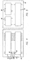
- the device electronics comprises a plurality of integrated circuit (IC) chips interconnected by means of a flexible interconnecting circuit (flex circuit) 54 that includes a plurality of electrical conductors arranged for electrically interconnecting the plurality of IC chips. More specifically and referring to Fig. 4, there is shown in schematic format, the flex circuit 54 in a flat open face up position upon which is mounted two IC chips 50 and 52. A representative interconnect between two IC chips is shown wherein a breakout 50A representing a signal line from IC chip 50 is connected to flex circuit terminal 46 and a breakout 52B representing a signal line from IC chip 52 is connected to flex circuit terminal 48 and an electrical flex circuit wire 56 electrically interconnects the breakouts so that they are in electrical communication with each other.
- a breakout 50A representing a signal line from IC chip 50
- a breakout 52B representing a signal line from IC chip 52
- Securing the breakouts to the corresponding flex circuit terminals may be accomplished by techniques known in the art, such as spot welding or soldering.
- the opposite face of the flex circuit 54 is shown in Fig. 5 with three IC chips 36, 42 and 44 mounted in a manner similar to that shown in Fig. 4. Any interconnects between IC chips on opposite faces of the flex circuit 54 may be accomplished by means of electrical conductors extending through the flex circuit.
- the flex circuit 54 is formed preferably of a flexible material such as a bendable plastic derivative to which may be adhered or imbedded, a plurality of electrical conductors in a manner known in the art. Fig.
- Fig. 6 illustrates the bendable nature of the flex circuit 54 where the flex circuit is bent along a central axis (not shown) so that the resultant circuit configuration is in a "U" shape with the ends 58 and 60 of the flex circuit, although not a requirement, being essentially in registration.
- Fig. 7 is a front elevation view of an alternate embodiment of the device of Fig. 6, showing the addition of electronic components such as capacitor 62 adapted for the delivery of a large amount of stimulation charge to tissue by means of conductive plates 28 and 30 and diode 64 used in the power supply module 36 for rectifying the time varying signal provided by coil 14.
- the entire medical device electronic circuitry is housed within the interior region of the hollow tube 12. The advantage to this novel configuration is the resultant economy of size providing an overall reduction in geometry of the medical device.
- a potting matrix preferably of silicon with a getter, is introduced into the interior region 32 to fill any voids existing between the device electronics and the inner wall of the hollow tube 12.
- the potting matrix tends to stabilize the device electronics within the interior region against relative movement between the electronics and hollow tube and the getter provides, among other things, increased hermeticity of the electronics.
Abstract
Description
- The present invention relates to a housing for the electronics of an implantable medical device, more specifically, a housing formed of a material capable of concentrating a magnetic field to which the housing is exposed.
- Implantable medical devices for remedial treatment of and compensation for cardiac, neural and muscular deficiencies are known in the art. These devices range from cardiac pacemakers as described in U. S. Patent No. 4,712,555 to Thornander et al., to microstimulators as described in U. S. Patent No. 6,208,894 to Schulman et al. The quest for minimization of such devices has provided, at least in the area of microstimulators, cylindrically shaped devices that range in size of about 6 mm in diameter and about 60 mm in axial length, see for example the device described in U. S. Patent No. 6,315,721 ('721). The device described in '721 is configured so that, the electronics is packaged in a housing in tandem with a wire wound ferrite core used as a source of recharging energy for the device electronics power supply. Furthermore, the electronics themselves is arranged in a lengthwise fashion within the device, thereby adding to the overall length of the device. This configuration ultimately gives rise to the stated overall device length. In view of the implant nature of such medical devices, even still further device miniaturization would prove advantageous to device implantation and extraction (if required), as well as patient comfort.
- The present invention addresses the quest for further miniaturization and provides a novel packaging and configuration of the medical device electronics within a wire wound hollow tube that markedly reduces the overall dimension of the device. In accordance with the invention, a hollow tube formed of a magnetic field concentrating material, such as ferrite, houses the device electronics. An electrically conductive wire coil is wound around the hollow tube and serves to generate time varying electrical signals when exposed to a time varying magnetic field. Since the hollow tube material concentrates the magnetic field to which the medical device is exposed, the resultant electrical signal generated by the coil, when exposed to the magnetic field, is maximized. In particular, because of what is known as the "skin effect", a majority of the magnetic field concentrating effect of a ferrite tube is in the outermost region of the tube. The wire coil is positioned to be in proximity to the concentrated magnetic field. By virtue of the coil and hollow tube arrangement, the interior region of the hollow tube is essentially free of magnetic field effects and therefore an excellent candidate for containing the medical device electronics. Moreover, the volume of the ferrite to produce the described magnetic field is minimized.
- In accordance with an aspect of the invention, the medical device electronics, in the form of a plurality of Integrated Circuit (IC) chips, are mounted to a flexible (flex) circuit having a network of interconnecting electrical vias or conductors positioned to accommodate interconnection between respective ones of the terminals of the IC chips. Due to the flexible nature of the flex circuit, the circuit is foldable to achieve a "U" shaped profile with the IC chips in face-to-face arrangement. Accordingly, the equivalent length of the IC chip loaded flex circuit is essentially reduced to about one-half of predecessor designs. The IC chip thickness is such that, with the flex circuit in the folded configuration, the flex circuit fits neatly into the interior region of the hollow tube.
- A protective sleeve encases the hollow tube and has fluid tight hermetically sealed end caps to insulate the device from body fluids. The sleeve is formed of a material, such as a ceramic, that is impervious to body fluids. Electrically conductive electrodes are mounted on the sleeve end caps for delivery of stimulation energy, generated by the device electronics, to body tissue with which they are in contact. The electrodes may also serve as antennae's for wireless communication with an external programming device.
- A potting matrix formed preferably of silicone, including a getter, is injected into the interior region of the hollow tube to fill any voids existing between the device electronics and the interior of the hollow tube. The matrix prevents the electronics from moving relative to the hollow tube and also provides a hermetically sealed environment for the device electronics.
- The above and other aspects, features and advantages of the present invention will become apparent from the following more particular description thereof presented in conjunction with the following drawings, wherein:
- Fig. 1 is a perspective view, in partial phantom, of an embodiment of the present invention;
- Fig. 2 is a side view of the embodiment of Fig. 1 including end caps;
- Fig. 3 is a block diagram of the electronic modules of the embodiment of Fig. 1;
- Fig. 4 is a simplified schematic view of one side of a flex circuit of the embodiment of Fig. 1, upon which device electronics IC chips are mounted;
- Fig. 5 is a simplified view of the other side of the flex circuit of the embodiment of Fig. 4, upon which device electronics IC chips are mounted;
- Fig. 6 is a partial side elevation view of the flex circuit of Figs. 4 and 5, mounted with IC chips and in the folded configuration; and
- Fig. 7 is a partial front elevation view of the embodiment of Fig. 6.
- The present invention is directed to a housing for an implantable medical device or microstimulator intended for implant beneath a patient's skin for the purpose of stimulation, parameter monitoring and data exchange. The stimulation function may, for example, be neural or muscular and the data exchange may be by way of a radio frequency (RF) communication link between the medical device and an external RF transmitter/receiver device. This description should not be taken in a limiting sense but rather for the purpose of describing the general principles of the invention.
- Referring now to Fig. 1, there is shown a perspective view of an embodiment of the medical device housing 10 of the present invention. The
housing 10 includes an elongated hollow, essentially cylindrically shapedtube 12. Although the description is in terms of a cylindrical shape, it is to be understood that alternate shapes such as, for example, oval or square, are appropriate substitutes for the housing shape. Thetube 12 is formed of a magnetic field condensing or concentrating material such as iron or a ferrous derivative. The preferred material is ferrite, due to its greater ability to concentrate magnetic fields to which it is exposed, in an area in and around the object formed of the ferrite. More specifically, the hollow ferrite tube provides a dense magnetic field localized at the outermost region of the tube due to the realized magnetic "skin effect". Wrapped aroundhollow tube 12 iscoil 14 formed of a thin electrically conductive filament wire typically being about forty-four (44) gauge. Thecoil 14 extends the length of thehollow tube 12 betweentube ends wall thickness dimension 21, measured radially, is about .24 mm. - A protective sleeve 22 (shown in phantom in Fig. 1) encases the
hollow tube 12 along its length with the sleeve having fluid tight hermetically sealedend caps sleeve 22 has a generally cylindrical cross-section and is formed of a material, such as ceramic, impervious to body fluids and accordingly the interior of the housing remains insulated from exposure to such body fluids. Theend caps end caps sleeve 22 and electricallyconductive plates end caps Conductive plates Sleeve 22 has anoutside diameter 31 of about 3.175 mm, which is about one-half the dimension of predecessor devices (see U. S. Pat. No. 6,315,721 incorporated herein by reference, in its entirety) and an axial length in the range of about 3.2 mm to 8 mm depending upon the desired amount of additional electrical circuitry, beyond that shown in Fig. 1, to be included in the housing. In this regard, the device of the present invention may be inserted beneath the skin of a patient by the use of a hypodermic type insertion tool (not shown) with greater ease and expediency than previously known. - Housed within the hollow tube
interior region 32 aredevice electronics 34. The device electronics comprises those modules necessary to carry out the stimulation, sensing and communication functions necessary for successful operation of the medical device (microstimulator). More specifically, and with reference to Fig. 3, there is shown in block diagram format, the component parts of the device electronics. Thecoil 14 is coupled topower supply 36 that supplies power to the individual circuits of the device. Thepower supply 36 includes rectifier circuitry and storage capacitors (not shown) to convert the time varying signal provided bycoil 14 to a direct current signal for use by the other circuits. Amagnetic sensor 38 is coupled topower supply 36 and serves to disable the power supply upon exposure of thesensor 38 to a strong magnetic field provided by a magnet when it is positioned in proximity to the medical device. This feature allows the medical device to be disabled once it has been determined that the device and device electronics should be shut down. An R-Fcommunication link module 52 serves to provide a communication link by means of wireless communication with anexternal controller 40. Theexternal programmer 40 provides programming information to program the medical device when to provide specific stimulation pulses, sense biological parameters and monitor neural responses. Thepulse generator 42, in response to instructions received from the communications link 52, provides preselected tissue stimulation pulses via matchingnetwork 44 andconductive plates conductive plates filter 50 amplifies and filters neural response signals received fromplates external controller 40 viacommunication link 40. - The device electronics comprises a plurality of integrated circuit (IC) chips interconnected by means of a flexible interconnecting circuit (flex circuit) 54 that includes a plurality of electrical conductors arranged for electrically interconnecting the plurality of IC chips. More specifically and referring to Fig. 4, there is shown in schematic format, the
flex circuit 54 in a flat open face up position upon which is mounted twoIC chips breakout 50A representing a signal line fromIC chip 50 is connected to flexcircuit terminal 46 and a breakout 52B representing a signal line fromIC chip 52 is connected to flexcircuit terminal 48 and an electricalflex circuit wire 56 electrically interconnects the breakouts so that they are in electrical communication with each other. Securing the breakouts to the corresponding flex circuit terminals may be accomplished by techniques known in the art, such as spot welding or soldering. The opposite face of theflex circuit 54 is shown in Fig. 5 with threeIC chips flex circuit 54 may be accomplished by means of electrical conductors extending through the flex circuit. Theflex circuit 54 is formed preferably of a flexible material such as a bendable plastic derivative to which may be adhered or imbedded, a plurality of electrical conductors in a manner known in the art. Fig. 6 illustrates the bendable nature of theflex circuit 54 where the flex circuit is bent along a central axis (not shown) so that the resultant circuit configuration is in a "U" shape with theends capacitor 62 adapted for the delivery of a large amount of stimulation charge to tissue by means ofconductive plates diode 64 used in thepower supply module 36 for rectifying the time varying signal provided bycoil 14. In all embodiments, the entire medical device electronic circuitry is housed within the interior region of thehollow tube 12. The advantage to this novel configuration is the resultant economy of size providing an overall reduction in geometry of the medical device. - Subsequent to positioning of the device electronics within the
hollow tube 12, a potting matrix, preferably of silicon with a getter, is introduced into theinterior region 32 to fill any voids existing between the device electronics and the inner wall of thehollow tube 12. The potting matrix tends to stabilize the device electronics within the interior region against relative movement between the electronics and hollow tube and the getter provides, among other things, increased hermeticity of the electronics.
Claims (14)
- A housing for an implantable microstimulator comprising:an elongated hollow tube formed of a magnetic field concentrating material, said hollow tube defining an interior region thereof for housing corresponding microstimulator electronics;an electrically conductive wire coil wound around an outer surface of the hollow tube and adapted for electrical communication with the microstimulator electronics; anda protective sleeve encasing the hollow tube and coil, the sleeve having first and second fluid tight sealed ends, the sleeve being formed of a material that is impervious to body fluids so as to insulate the hollow tube and coil from contact with said body fluids.
- The housing of claim 1, wherein the magnetic field concentrating material comprises a ferrous material.
- The housing of claim 2, wherein the ferrous material is ferrite.
- The housing of any one of claims 1 to 3, wherein the protective sleeve is formed of a ceramic material.
- The housing of any one of claims 1 to 4, wherein the microstimulator electronics positioned within the interior region of the hollow tube comprises at least one integrated circuit (IC) chip in electrical communication with the coil.
- The housing of claim 5, wherein the at least one IC chip comprises at least two IC chip's electrically interconnected by an electrically conductive flex circuit, wherein a selected electrical terminal contact on one IC chip is electrically connected to a selected electrical terminal contact on the other IC chip by the flex circuit.
- The housing of claim 6, wherein the flex circuit is flexible so as to provide rotational movement of one IC chip relative to the other IC chip such that they are positionable in close proximity to one another in face-to-face fashion.
- The housing of claim 5, 6 or 7 wherein the interior region of the hollow tube includes a silicone potting matrix sufficient to fill any voids existing within the hollow tube subsequent to the placement of the medical device electronics therein.
- The housing of claim 8, wherein the potting matrix includes a getter for absorbing any water introduced within said an interior region.
- The housing of any one of claims 1 to 9, wherein the microstimulator electronics is powered by a rechargeable battery, the microstimulator electronics further including a rectifier circuit coupled to the rechargeable battery, said rectifier circuit being in electrical communication with the coil, whereupon exposure of the coil to a varying magnetic field causes electrical currents to be generated within the coil and rectified in a manner to recharge the battery.
- The housing of any one of claims 1 to 10, wherein the microstimulator electronics includes radio frequency (RF) transmission and receiver circuitry wherein the coil is electrically coupled to and adapted to communicate with the RF circuitry as an antenna therefore.
- The housing of any one of claims 1 to 11, wherein the protective sleeve has an outside diameter in the range of about 3.2 millimeters to 8.0 millimeters.
- The housing of any one of claims 1 to 12, wherein the coil has turns in the range of about 10 to 600.
- A housing comprising:an elongated hollow tube formed of a magnetic field concentrating material, said hollow tube defining an interior region adapted for housing electronic circuitry;an electrically conductive wire coil wound around an outer surface of the hollow tube and adapted for electrical communication with the electronic circuitry; anda protective sleeve encasing the hollow tube and coil.
Applications Claiming Priority (2)
| Application Number | Priority Date | Filing Date | Title |
|---|---|---|---|
| US10/601,723 US7239921B2 (en) | 2003-06-23 | 2003-06-23 | Housing for an implantable medical device |
| US601723 | 2003-06-23 |
Publications (3)
| Publication Number | Publication Date |
|---|---|
| EP1491235A2 true EP1491235A2 (en) | 2004-12-29 |
| EP1491235A3 EP1491235A3 (en) | 2005-01-19 |
| EP1491235B1 EP1491235B1 (en) | 2009-07-15 |
Family
ID=33418606
Family Applications (1)
| Application Number | Title | Priority Date | Filing Date |
|---|---|---|---|
| EP04251533A Expired - Lifetime EP1491235B1 (en) | 2003-06-23 | 2004-03-18 | Implantable medical device |
Country Status (3)
| Country | Link |
|---|---|
| US (1) | US7239921B2 (en) |
| EP (1) | EP1491235B1 (en) |
| DE (1) | DE602004021991D1 (en) |
Cited By (3)
| Publication number | Priority date | Publication date | Assignee | Title |
|---|---|---|---|---|
| DE102005020071A1 (en) * | 2005-04-22 | 2006-10-26 | Biotronik Crm Patent Ag | Pacemaker |
| EP1886628A3 (en) * | 2006-08-11 | 2008-03-19 | Zarlink Semiconductor Limited | Antenna and body implant |
| WO2011130596A1 (en) * | 2010-04-15 | 2011-10-20 | Med-El Elektromedizinische Geraete Gmbh | Inductive link with ferrite sheets |
Families Citing this family (45)
| Publication number | Priority date | Publication date | Assignee | Title |
|---|---|---|---|---|
| US8239045B2 (en) | 2003-06-04 | 2012-08-07 | Synecor Llc | Device and method for retaining a medical device within a vessel |
| US7617007B2 (en) | 2003-06-04 | 2009-11-10 | Synecor Llc | Method and apparatus for retaining medical implants within body vessels |
| US7529589B2 (en) * | 2003-06-04 | 2009-05-05 | Synecor Llc | Intravascular electrophysiological system and methods |
| US7082336B2 (en) * | 2003-06-04 | 2006-07-25 | Synecor, Llc | Implantable intravascular device for defibrillation and/or pacing |
| US7747335B2 (en) * | 2003-12-12 | 2010-06-29 | Synecor Llc | Implantable medical device having pre-implant exoskeleton |
| US9308382B2 (en) | 2004-06-10 | 2016-04-12 | Medtronic Urinary Solutions, Inc. | Implantable pulse generator systems and methods for providing functional and/or therapeutic stimulation of muscles and/or nerves and/or central nervous system tissue |
| US8165692B2 (en) * | 2004-06-10 | 2012-04-24 | Medtronic Urinary Solutions, Inc. | Implantable pulse generator power management |
| US9205255B2 (en) | 2004-06-10 | 2015-12-08 | Medtronic Urinary Solutions, Inc. | Implantable pulse generator systems and methods for providing functional and/or therapeutic stimulation of muscles and/or nerves and/or central nervous system tissue |
| FR2872695B1 (en) * | 2004-07-09 | 2007-10-05 | Hartmann Thierry | ALARM DEVICE FOR PREVENTING SUDDEN INFANT DEATH |
| US7706892B2 (en) * | 2005-01-20 | 2010-04-27 | Boston Scientific Neuromodulation Corporation | Implantable microstimulator with plastic housing and methods of manufacture and use |
| US7376466B2 (en) * | 2005-01-26 | 2008-05-20 | Boston Scientific Neuromodulation Corporation | Casings for implantable stimulators and methods of making the same |
| US7957805B2 (en) * | 2005-06-01 | 2011-06-07 | Boston Scientific Neuromodulation Corporation | Implantable microstimulator with external electrodes disposed on a film substrate and methods of manufacture and use |
| US7288928B2 (en) * | 2005-06-27 | 2007-10-30 | Greenwich Instruments Co., Inc. | Solenoidal Hall effects current sensor |
| WO2007112004A2 (en) | 2006-03-24 | 2007-10-04 | Medtronic, Inc | Implantable medical device and lithium battery |
| US20070265673A1 (en) * | 2006-04-03 | 2007-11-15 | Terrance Ransbury | Flexible interconnect assembly for implantable medical devices |
| US9480846B2 (en) | 2006-05-17 | 2016-11-01 | Medtronic Urinary Solutions, Inc. | Systems and methods for patient control of stimulation systems |
| US20080103543A1 (en) * | 2006-10-31 | 2008-05-01 | Medtronic, Inc. | Implantable medical device with titanium alloy housing |
| US7857819B2 (en) * | 2006-11-30 | 2010-12-28 | Boston Scientific Neuromodulation Corporation | Implant tool for use with a microstimulator |
| US8311633B2 (en) * | 2006-12-04 | 2012-11-13 | Synecor Llc | Intravascular implantable device having superior anchoring arrangement |
| US20080147168A1 (en) * | 2006-12-04 | 2008-06-19 | Terrance Ransbury | Intravascular implantable device having detachable tether arrangement |
| US8514060B2 (en) * | 2008-05-21 | 2013-08-20 | Mitomo Corporation | Wireless identification tag |
| WO2010096774A2 (en) * | 2009-02-20 | 2010-08-26 | Endurance Rhythm, Inc. | Implantable micro-generator devices with optimized configuration, methods of use, systems and kits therefor |
| WO2010144916A2 (en) * | 2009-06-12 | 2010-12-16 | Innerpulse, Inc. | Methods and systems for anti-thrombotic intravascular implantable devices |
| US20110004288A1 (en) * | 2009-06-12 | 2011-01-06 | Terrance Ransbury | Intravascular implantable device having integrated anchor mechanism |
| WO2013111137A2 (en) | 2012-01-26 | 2013-08-01 | Rainbow Medical Ltd. | Wireless neurqstimulatqrs |
| JP5865822B2 (en) * | 2012-04-17 | 2016-02-17 | 日東電工株式会社 | Method for forming magnetic field space |
| CN104582635B (en) | 2012-08-22 | 2017-06-20 | 加州理工学院 | For the wireless power transmission system of 3 coils of ocular implant |
| WO2014087337A1 (en) | 2012-12-06 | 2014-06-12 | Bluewind Medical Ltd. | Delivery of implantable neurostimulators |
| EP2928551B1 (en) | 2012-12-07 | 2024-02-21 | Medtronic, Inc. | Minimally invasive implantable neurostimulation system |
| US20190101426A1 (en) * | 2013-06-14 | 2019-04-04 | Dresser, Llc | Maintaining redundant data on a gas meter |
| US10610693B2 (en) | 2013-07-11 | 2020-04-07 | Newpace Ltd. | Battery and electronics integration in a flexible implantable medical device |
| DE102014009136B4 (en) * | 2014-06-18 | 2017-04-27 | Forschungszentrum Jülich GmbH | Housing for a medical implant |
| EP3010084B1 (en) * | 2014-10-17 | 2019-09-04 | Synoste OY | A device with a receiving antenna and a related power transfer system |
| EP3359254B1 (en) | 2015-10-09 | 2019-09-04 | Cardiac Pacemakers, Inc. | Connector block assembly |
| US10105540B2 (en) | 2015-11-09 | 2018-10-23 | Bluewind Medical Ltd. | Optimization of application of current |
| EP3432975B1 (en) | 2016-03-21 | 2024-02-14 | Nalu Medical, Inc. | Devices for positioning external devices in relation to implanted devices |
| EP3484577A4 (en) | 2016-07-18 | 2020-03-25 | Nalu Medical, Inc. | Methods and systems for treating pelvic disorders and pain conditions |
| CN109996585B (en) | 2016-11-21 | 2023-06-13 | 心脏起搏器股份公司 | Implantable medical device with magnetically permeable housing and induction coil disposed around the housing |
| US10124178B2 (en) | 2016-11-23 | 2018-11-13 | Bluewind Medical Ltd. | Implant and delivery tool therefor |
| WO2018156953A1 (en) | 2017-02-24 | 2018-08-30 | Nalu Medical, Inc. | Apparatus with sequentially implanted stimulators |
| EP3621689A4 (en) | 2017-05-09 | 2021-01-27 | Nalu Medical, Inc. | Stimulation apparatus |
| US20180353764A1 (en) | 2017-06-13 | 2018-12-13 | Bluewind Medical Ltd. | Antenna configuration |
| WO2019036568A1 (en) | 2017-08-18 | 2019-02-21 | Cardiac Pacemakers, Inc. | Implantable medical device with a flux concentrator and a receiving coil disposed about the flux concentrator |
| WO2019183247A1 (en) | 2018-03-20 | 2019-09-26 | Second Heart Assist, Inc. | Circulatory assist pump |
| US11400299B1 (en) | 2021-09-14 | 2022-08-02 | Rainbow Medical Ltd. | Flexible antenna for stimulator |
Citations (2)
| Publication number | Priority date | Publication date | Assignee | Title |
|---|---|---|---|---|
| US4712555A (en) | 1984-10-19 | 1987-12-15 | Siemens-Elema Ab | Physiologically responsive pacemaker and method of adjusting the pacing interval thereof |
| US6208894B1 (en) | 1997-02-26 | 2001-03-27 | Alfred E. Mann Foundation For Scientific Research And Advanced Bionics | System of implantable devices for monitoring and/or affecting body parameters |
Family Cites Families (14)
| Publication number | Priority date | Publication date | Assignee | Title |
|---|---|---|---|---|
| DE2614921C3 (en) * | 1976-04-07 | 1979-07-12 | Lindemann Maschinenfabrik Gmbh, 4000 Duesseldorf | Changing device for containers arranged in front of the discharge opening of a garbage compactor |
| US4071032A (en) * | 1976-01-29 | 1978-01-31 | Pacesetter Systems Inc. | Implantable living tissue stimulators |
| US4041955A (en) * | 1976-01-29 | 1977-08-16 | Pacesetter Systems Inc. | Implantable living tissue stimulator with an improved hermetic metal container |
| US4333469A (en) * | 1979-07-20 | 1982-06-08 | Telectronics Pty. Ltd. | Bone growth stimulator |
| US5193540A (en) | 1991-12-18 | 1993-03-16 | Alfred E. Mann Foundation For Scientific Research | Structure and method of manufacture of an implantable microstimulator |
| US5193539A (en) | 1991-12-18 | 1993-03-16 | Alfred E. Mann Foundation For Scientific Research | Implantable microstimulator |
| US6164284A (en) * | 1997-02-26 | 2000-12-26 | Schulman; Joseph H. | System of implantable devices for monitoring and/or affecting body parameters |
| US6026818A (en) | 1998-03-02 | 2000-02-22 | Blair Port Ltd. | Tag and detection device |
| DE19821857A1 (en) * | 1998-05-15 | 1999-11-18 | Biotronik Mess & Therapieg | Highly integrated electronic circuit, especially for use in pacemakers |
| US6081070A (en) | 1998-05-22 | 2000-06-27 | Matsushita Electric Works R & D Laboratories Inc. | High-frequency electrodeless fluorescent lamp |
| US6405367B1 (en) * | 1998-06-05 | 2002-06-11 | Hewlett-Packard Company | Apparatus and method for increasing the performance of Java programs running on a server |
| EP1048324A3 (en) | 1999-04-30 | 2002-10-16 | Medtronic, Inc. | Medical Li+ rechargeable powered implantable stimulator |
| AU2001296403A1 (en) | 2000-10-11 | 2002-04-22 | Alfred E. Mann Foundation For Scientific Research | Improved antenna for miniature implanted medical device |
| US7120992B2 (en) * | 2002-06-28 | 2006-10-17 | Advanced Bionics Corporation | Method of making an electronic module |
-
2003
- 2003-06-23 US US10/601,723 patent/US7239921B2/en active Active
-
2004
- 2004-03-18 DE DE602004021991T patent/DE602004021991D1/en not_active Expired - Lifetime
- 2004-03-18 EP EP04251533A patent/EP1491235B1/en not_active Expired - Lifetime
Patent Citations (3)
| Publication number | Priority date | Publication date | Assignee | Title |
|---|---|---|---|---|
| US4712555A (en) | 1984-10-19 | 1987-12-15 | Siemens-Elema Ab | Physiologically responsive pacemaker and method of adjusting the pacing interval thereof |
| US6208894B1 (en) | 1997-02-26 | 2001-03-27 | Alfred E. Mann Foundation For Scientific Research And Advanced Bionics | System of implantable devices for monitoring and/or affecting body parameters |
| US6315721B2 (en) | 1997-02-26 | 2001-11-13 | Alfred E. Mann Foundation For Scientific Research | System of implantable devices for monitoring and/or affecting body parameters |
Cited By (5)
| Publication number | Priority date | Publication date | Assignee | Title |
|---|---|---|---|---|
| DE102005020071A1 (en) * | 2005-04-22 | 2006-10-26 | Biotronik Crm Patent Ag | Pacemaker |
| US8032219B2 (en) | 2005-04-22 | 2011-10-04 | Biotronik Crm Patent Ag | Cardiac pacemaker having a sealed oblong housing |
| EP1886628A3 (en) * | 2006-08-11 | 2008-03-19 | Zarlink Semiconductor Limited | Antenna and body implant |
| WO2011130596A1 (en) * | 2010-04-15 | 2011-10-20 | Med-El Elektromedizinische Geraete Gmbh | Inductive link with ferrite sheets |
| CN102892463A (en) * | 2010-04-15 | 2013-01-23 | Med-El电气医疗器械有限公司 | Inductive link with ferrite sheets |
Also Published As
| Publication number | Publication date |
|---|---|
| US20040260372A1 (en) | 2004-12-23 |
| EP1491235B1 (en) | 2009-07-15 |
| EP1491235A3 (en) | 2005-01-19 |
| DE602004021991D1 (en) | 2009-08-27 |
| US7239921B2 (en) | 2007-07-03 |
Similar Documents
| Publication | Publication Date | Title |
|---|---|---|
| EP1491235B1 (en) | Implantable medical device | |
| ES2426255T3 (en) | Microstimulator that has a built-in power source and a two-way telemetry system | |
| US7444180B2 (en) | Implantable microstimulator with dissecting tip and/or retrieving anchor and methods of manufacture and use | |
| US8301266B1 (en) | Structure for placement of an implantable device | |
| US7174212B1 (en) | Implantable medical device having a casing providing high-speed telemetry | |
| US6505072B1 (en) | Implantable electronic stimulator having isolation transformer input to telemetry circuits | |
| JP4485556B2 (en) | Battery powered patient subcutaneous insertion device | |
| US5358514A (en) | Implantable microdevice with self-attaching electrodes | |
| US7729758B2 (en) | Magnetically coupled microstimulators | |
| CA2271080C (en) | Implantable device with a charging current feed arrangement which has a receiving coil | |
| US7765005B2 (en) | Apparatus and process for reducing the susceptability of active implantable medical devices to medical procedures such as magnetic resonance imaging | |
| US6931284B2 (en) | Implantable medical device with air core antenna assembly | |
| US20050283167A1 (en) | Medical device with an electrically conductive anti-antenna member | |
| US20070168006A1 (en) | Medical device with an electrically conductive anti-antenna member | |
| US20070168005A1 (en) | Medical device with an electrically conductive anti-antenna member | |
| US20120165912A1 (en) | Medical device with an electrically conductive anti-antenna member | |
| AU2014315377B2 (en) | Systems and methods for reducing electromagnetic field-induced heating from an implantable pulse generator | |
| US20140172047A1 (en) | Implantable pulse generator for stimulation of a neurological cellular mass | |
| US20050288751A1 (en) | Medical device with an electrically conductive anti-antenna member | |
| JP2021532895A (en) | Implantable equipment and how to assemble the implantable equipment | |
| US20220134096A1 (en) | Implantable Device Comprising a Coil Arrangement | |
| US20090118779A1 (en) | Modular System For A Wireless Implantable Device | |
| US20070173911A1 (en) | Medical device with an electrically conductive anti-antenna member | |
| US20050283214A1 (en) | Medical device with an electrically conductive anti-antenna member | |
| US20050288750A1 (en) | Medical device with an electrically conductive anti-antenna member |
Legal Events
| Date | Code | Title | Description |
|---|---|---|---|
| PUAI | Public reference made under article 153(3) epc to a published international application that has entered the european phase |
Free format text: ORIGINAL CODE: 0009012 |
|
| PUAL | Search report despatched |
Free format text: ORIGINAL CODE: 0009013 |
|
| AK | Designated contracting states |
Kind code of ref document: A2 Designated state(s): AT BE BG CH CY CZ DE DK EE ES FI FR GB GR HU IE IT LI LU MC NL PL PT RO SE SI SK TR |
|
| AX | Request for extension of the european patent |
Extension state: AL HR LT LV MK |
|
| AK | Designated contracting states |
Kind code of ref document: A3 Designated state(s): AT BE BG CH CY CZ DE DK EE ES FI FR GB GR HU IE IT LI LU MC NL PL PT RO SE SI SK TR |
|
| AX | Request for extension of the european patent |
Extension state: AL HR LT LV MK |
|
| RIC1 | Information provided on ipc code assigned before grant |
Ipc: 7A 61N 1/375 A Ipc: 7A 61N 1/378 B |
|
| 17P | Request for examination filed |
Effective date: 20050309 |
|
| AKX | Designation fees paid |
Designated state(s): DE GB |
|
| 17Q | First examination report despatched |
Effective date: 20071116 |
|
| GRAP | Despatch of communication of intention to grant a patent |
Free format text: ORIGINAL CODE: EPIDOSNIGR1 |
|
| RTI1 | Title (correction) |
Free format text: IMPLANTABLE MEDICAL DEVICE |
|
| GRAS | Grant fee paid |
Free format text: ORIGINAL CODE: EPIDOSNIGR3 |
|
| GRAA | (expected) grant |
Free format text: ORIGINAL CODE: 0009210 |
|
| AK | Designated contracting states |
Kind code of ref document: B1 Designated state(s): DE GB |
|
| REG | Reference to a national code |
Ref country code: GB Ref legal event code: FG4D |
|
| REF | Corresponds to: |
Ref document number: 602004021991 Country of ref document: DE Date of ref document: 20090827 Kind code of ref document: P |
|
| PLBE | No opposition filed within time limit |
Free format text: ORIGINAL CODE: 0009261 |
|
| STAA | Information on the status of an ep patent application or granted ep patent |
Free format text: STATUS: NO OPPOSITION FILED WITHIN TIME LIMIT |
|
| 26N | No opposition filed |
Effective date: 20100416 |
|
| PGFP | Annual fee paid to national office [announced via postgrant information from national office to epo] |
Ref country code: GB Payment date: 20230327 Year of fee payment: 20 Ref country code: DE Payment date: 20230329 Year of fee payment: 20 |
|
| REG | Reference to a national code |
Ref country code: DE Ref legal event code: R071 Ref document number: 602004021991 Country of ref document: DE |
|
| REG | Reference to a national code |
Ref country code: GB Ref legal event code: PE20 Expiry date: 20240317 |