EP1491139A2 - Bend-responsive catheter - Google Patents
Bend-responsive catheter Download PDFInfo
- Publication number
- EP1491139A2 EP1491139A2 EP20040077532 EP04077532A EP1491139A2 EP 1491139 A2 EP1491139 A2 EP 1491139A2 EP 20040077532 EP20040077532 EP 20040077532 EP 04077532 A EP04077532 A EP 04077532A EP 1491139 A2 EP1491139 A2 EP 1491139A2
- Authority
- EP
- European Patent Office
- Prior art keywords
- probe
- sensor
- bend
- catheter
- sensing element
- Prior art date
- Legal status (The legal status is an assumption and is not a legal conclusion. Google has not performed a legal analysis and makes no representation as to the accuracy of the status listed.)
- Granted
Links
Images


Classifications
-
- A—HUMAN NECESSITIES
- A61—MEDICAL OR VETERINARY SCIENCE; HYGIENE
- A61B—DIAGNOSIS; SURGERY; IDENTIFICATION
- A61B5/00—Measuring for diagnostic purposes; Identification of persons
- A61B5/24—Detecting, measuring or recording bioelectric or biomagnetic signals of the body or parts thereof
- A61B5/25—Bioelectric electrodes therefor
- A61B5/279—Bioelectric electrodes therefor specially adapted for particular uses
- A61B5/28—Bioelectric electrodes therefor specially adapted for particular uses for electrocardiography [ECG]
- A61B5/283—Invasive
- A61B5/287—Holders for multiple electrodes, e.g. electrode catheters for electrophysiological study [EPS]
-
- A—HUMAN NECESSITIES
- A61—MEDICAL OR VETERINARY SCIENCE; HYGIENE
- A61B—DIAGNOSIS; SURGERY; IDENTIFICATION
- A61B1/00—Instruments for performing medical examinations of the interior of cavities or tubes of the body by visual or photographical inspection, e.g. endoscopes; Illuminating arrangements therefor
- A61B1/005—Flexible endoscopes
- A61B1/009—Flexible endoscopes with bending or curvature detection of the insertion part
-
- A—HUMAN NECESSITIES
- A61—MEDICAL OR VETERINARY SCIENCE; HYGIENE
- A61B—DIAGNOSIS; SURGERY; IDENTIFICATION
- A61B34/00—Computer-aided surgery; Manipulators or robots specially adapted for use in surgery
- A61B34/20—Surgical navigation systems; Devices for tracking or guiding surgical instruments, e.g. for frameless stereotaxis
-
- A—HUMAN NECESSITIES
- A61—MEDICAL OR VETERINARY SCIENCE; HYGIENE
- A61B—DIAGNOSIS; SURGERY; IDENTIFICATION
- A61B5/00—Measuring for diagnostic purposes; Identification of persons
- A61B5/06—Devices, other than using radiation, for detecting or locating foreign bodies ; determining position of probes within or on the body of the patient
- A61B5/061—Determining position of a probe within the body employing means separate from the probe, e.g. sensing internal probe position employing impedance electrodes on the surface of the body
-
- A—HUMAN NECESSITIES
- A61—MEDICAL OR VETERINARY SCIENCE; HYGIENE
- A61B—DIAGNOSIS; SURGERY; IDENTIFICATION
- A61B5/00—Measuring for diagnostic purposes; Identification of persons
- A61B5/06—Devices, other than using radiation, for detecting or locating foreign bodies ; determining position of probes within or on the body of the patient
- A61B5/065—Determining position of the probe employing exclusively positioning means located on or in the probe, e.g. using position sensors arranged on the probe
-
- A—HUMAN NECESSITIES
- A61—MEDICAL OR VETERINARY SCIENCE; HYGIENE
- A61B—DIAGNOSIS; SURGERY; IDENTIFICATION
- A61B5/00—Measuring for diagnostic purposes; Identification of persons
- A61B5/68—Arrangements of detecting, measuring or recording means, e.g. sensors, in relation to patient
- A61B5/6846—Arrangements of detecting, measuring or recording means, e.g. sensors, in relation to patient specially adapted to be brought in contact with an internal body part, i.e. invasive
- A61B5/6885—Monitoring or controlling sensor contact pressure
-
- A—HUMAN NECESSITIES
- A61—MEDICAL OR VETERINARY SCIENCE; HYGIENE
- A61M—DEVICES FOR INTRODUCING MEDIA INTO, OR ONTO, THE BODY; DEVICES FOR TRANSDUCING BODY MEDIA OR FOR TAKING MEDIA FROM THE BODY; DEVICES FOR PRODUCING OR ENDING SLEEP OR STUPOR
- A61M25/00—Catheters; Hollow probes
- A61M25/01—Introducing, guiding, advancing, emplacing or holding catheters
- A61M25/0105—Steering means as part of the catheter or advancing means; Markers for positioning
-
- A—HUMAN NECESSITIES
- A61—MEDICAL OR VETERINARY SCIENCE; HYGIENE
- A61B—DIAGNOSIS; SURGERY; IDENTIFICATION
- A61B1/00—Instruments for performing medical examinations of the interior of cavities or tubes of the body by visual or photographical inspection, e.g. endoscopes; Illuminating arrangements therefor
- A61B1/005—Flexible endoscopes
- A61B1/0051—Flexible endoscopes with controlled bending of insertion part
-
- A—HUMAN NECESSITIES
- A61—MEDICAL OR VETERINARY SCIENCE; HYGIENE
- A61B—DIAGNOSIS; SURGERY; IDENTIFICATION
- A61B17/00—Surgical instruments, devices or methods, e.g. tourniquets
- A61B17/34—Trocars; Puncturing needles
- A61B17/3403—Needle locating or guiding means
-
- A—HUMAN NECESSITIES
- A61—MEDICAL OR VETERINARY SCIENCE; HYGIENE
- A61B—DIAGNOSIS; SURGERY; IDENTIFICATION
- A61B18/00—Surgical instruments, devices or methods for transferring non-mechanical forms of energy to or from the body
- A61B18/18—Surgical instruments, devices or methods for transferring non-mechanical forms of energy to or from the body by applying electromagnetic radiation, e.g. microwaves
- A61B18/20—Surgical instruments, devices or methods for transferring non-mechanical forms of energy to or from the body by applying electromagnetic radiation, e.g. microwaves using laser
- A61B18/22—Surgical instruments, devices or methods for transferring non-mechanical forms of energy to or from the body by applying electromagnetic radiation, e.g. microwaves using laser the beam being directed along or through a flexible conduit, e.g. an optical fibre; Couplings or hand-pieces therefor
- A61B18/24—Surgical instruments, devices or methods for transferring non-mechanical forms of energy to or from the body by applying electromagnetic radiation, e.g. microwaves using laser the beam being directed along or through a flexible conduit, e.g. an optical fibre; Couplings or hand-pieces therefor with a catheter
-
- A—HUMAN NECESSITIES
- A61—MEDICAL OR VETERINARY SCIENCE; HYGIENE
- A61B—DIAGNOSIS; SURGERY; IDENTIFICATION
- A61B17/00—Surgical instruments, devices or methods, e.g. tourniquets
- A61B17/00234—Surgical instruments, devices or methods, e.g. tourniquets for minimally invasive surgery
- A61B2017/00238—Type of minimally invasive operation
- A61B2017/00243—Type of minimally invasive operation cardiac
- A61B2017/00247—Making holes in the wall of the heart, e.g. laser Myocardial revascularization
-
- A—HUMAN NECESSITIES
- A61—MEDICAL OR VETERINARY SCIENCE; HYGIENE
- A61B—DIAGNOSIS; SURGERY; IDENTIFICATION
- A61B18/00—Surgical instruments, devices or methods for transferring non-mechanical forms of energy to or from the body
- A61B2018/00315—Surgical instruments, devices or methods for transferring non-mechanical forms of energy to or from the body for treatment of particular body parts
- A61B2018/00345—Vascular system
- A61B2018/00351—Heart
- A61B2018/00392—Transmyocardial revascularisation
-
- A—HUMAN NECESSITIES
- A61—MEDICAL OR VETERINARY SCIENCE; HYGIENE
- A61B—DIAGNOSIS; SURGERY; IDENTIFICATION
- A61B18/00—Surgical instruments, devices or methods for transferring non-mechanical forms of energy to or from the body
- A61B18/18—Surgical instruments, devices or methods for transferring non-mechanical forms of energy to or from the body by applying electromagnetic radiation, e.g. microwaves
- A61B18/20—Surgical instruments, devices or methods for transferring non-mechanical forms of energy to or from the body by applying electromagnetic radiation, e.g. microwaves using laser
- A61B18/22—Surgical instruments, devices or methods for transferring non-mechanical forms of energy to or from the body by applying electromagnetic radiation, e.g. microwaves using laser the beam being directed along or through a flexible conduit, e.g. an optical fibre; Couplings or hand-pieces therefor
- A61B2018/2255—Optical elements at the distal end of probe tips
- A61B2018/2272—Optical elements at the distal end of probe tips with reflective or refractive surfaces for deflecting the beam
-
- A—HUMAN NECESSITIES
- A61—MEDICAL OR VETERINARY SCIENCE; HYGIENE
- A61B—DIAGNOSIS; SURGERY; IDENTIFICATION
- A61B34/00—Computer-aided surgery; Manipulators or robots specially adapted for use in surgery
- A61B34/20—Surgical navigation systems; Devices for tracking or guiding surgical instruments, e.g. for frameless stereotaxis
- A61B2034/2046—Tracking techniques
- A61B2034/2051—Electromagnetic tracking systems
-
- A—HUMAN NECESSITIES
- A61—MEDICAL OR VETERINARY SCIENCE; HYGIENE
- A61B—DIAGNOSIS; SURGERY; IDENTIFICATION
- A61B90/00—Instruments, implements or accessories specially adapted for surgery or diagnosis and not covered by any of the groups A61B1/00 - A61B50/00, e.g. for luxation treatment or for protecting wound edges
- A61B90/39—Markers, e.g. radio-opaque or breast lesions markers
- A61B2090/3954—Markers, e.g. radio-opaque or breast lesions markers magnetic, e.g. NMR or MRI
-
- A—HUMAN NECESSITIES
- A61—MEDICAL OR VETERINARY SCIENCE; HYGIENE
- A61B—DIAGNOSIS; SURGERY; IDENTIFICATION
- A61B8/00—Diagnosis using ultrasonic, sonic or infrasonic waves
- A61B8/08—Detecting organic movements or changes, e.g. tumours, cysts, swellings
- A61B8/0833—Detecting organic movements or changes, e.g. tumours, cysts, swellings involving detecting or locating foreign bodies or organic structures
-
- A—HUMAN NECESSITIES
- A61—MEDICAL OR VETERINARY SCIENCE; HYGIENE
- A61M—DEVICES FOR INTRODUCING MEDIA INTO, OR ONTO, THE BODY; DEVICES FOR TRANSDUCING BODY MEDIA OR FOR TAKING MEDIA FROM THE BODY; DEVICES FOR PRODUCING OR ENDING SLEEP OR STUPOR
- A61M25/00—Catheters; Hollow probes
- A61M25/01—Introducing, guiding, advancing, emplacing or holding catheters
- A61M25/0105—Steering means as part of the catheter or advancing means; Markers for positioning
- A61M2025/0166—Sensors, electrodes or the like for guiding the catheter to a target zone, e.g. image guided or magnetically guided
-
- A—HUMAN NECESSITIES
- A61—MEDICAL OR VETERINARY SCIENCE; HYGIENE
- A61M—DEVICES FOR INTRODUCING MEDIA INTO, OR ONTO, THE BODY; DEVICES FOR TRANSDUCING BODY MEDIA OR FOR TAKING MEDIA FROM THE BODY; DEVICES FOR PRODUCING OR ENDING SLEEP OR STUPOR
- A61M25/00—Catheters; Hollow probes
- A61M25/0021—Catheters; Hollow probes characterised by the form of the tubing
- A61M25/0041—Catheters; Hollow probes characterised by the form of the tubing pre-formed, e.g. specially adapted to fit with the anatomy of body channels
-
- A—HUMAN NECESSITIES
- A61—MEDICAL OR VETERINARY SCIENCE; HYGIENE
- A61M—DEVICES FOR INTRODUCING MEDIA INTO, OR ONTO, THE BODY; DEVICES FOR TRANSDUCING BODY MEDIA OR FOR TAKING MEDIA FROM THE BODY; DEVICES FOR PRODUCING OR ENDING SLEEP OR STUPOR
- A61M25/00—Catheters; Hollow probes
- A61M25/01—Introducing, guiding, advancing, emplacing or holding catheters
- A61M25/0105—Steering means as part of the catheter or advancing means; Markers for positioning
- A61M25/0133—Tip steering devices
-
- A—HUMAN NECESSITIES
- A61—MEDICAL OR VETERINARY SCIENCE; HYGIENE
- A61N—ELECTROTHERAPY; MAGNETOTHERAPY; RADIATION THERAPY; ULTRASOUND THERAPY
- A61N1/00—Electrotherapy; Circuits therefor
- A61N1/02—Details
- A61N1/04—Electrodes
- A61N1/05—Electrodes for implantation or insertion into the body, e.g. heart electrode
Definitions
- the present invention relates generally to cardiac diagnostic and therapeutic systems, and specifically to invasive medical probes that may be used to map the interior surfaces of the heart.
- Position-responsive cardiac catheters are known in the art. Such catheters are generally inserted percutaneously and fed through one or more major blood vessels into a chamber of the heart.
- a position-sensing device in the catheter typically near the catheter's distal end, gives rise to signals that are used to determine the position of the device (and hence of the catheter) relative to a frame of reference that is fixed either externally to the body or to the heart itself.
- the position-sensing device may be active or passive and may operate by generating or receiving electrical, magnetic or ultrasonic energy fields or other suitable forms of energy known in the art.
- U.S. patent 5,391,199 which is incorporated herein by reference, describes a position-responsive catheter comprising a miniature sensor coil contained in the catheter's distal end.
- the coil generates electrical signals in response to externally-applied magnetic fields, which are produced by field-generator coils placed outside the patient's body.
- the electrical signals are analyzed to determine three-dimensional position coordinates of the coil.
- Position-sensing devices may be placed in a known, mutually-fixed spatial relation at or adjacent to the distal end of a catheter, as described, for example, in PCT patent application no. PCT/IL97/00009, which is assigned to the assignee of the present application and whose disclosure is incorporated herein by reference.
- This application describes a catheter having a substantially rigid structure at its distal end, to which one or more position sensors are fixed. The sensors are used to determine the position and orientation of the structure, preferably for use in mapping electrical activity in the heart.
- the structure itself is substantially rigid, the remainder of the catheter is generally flexible, and the position sensors do not provide coordinate information regarding any points on the catheter proximal to the structure.
- the sensor coil may be used to determine the spatial configuration or course of flexible endoscope within the body of a subject in one of two ways: (1) By passing the coil through an internal lumen of the endoscope, for example, the endoscope's biopsy tube, and externally tracking the coil's location while the endoscope is held stationary; or (2) By distributing a plurality of the coils, preferably about a dozen, along the length of the endoscope and determining all of the coils' locations.
- the position coordinates determined with respect to each location of the coil (when a single coil is used) or to all the coils (when the plurality of coils are used) are taken together to interpolatively reconstruct the spatial configuration of the endoscope within the intestines of the subject, for example, and thereby estimate the corresponding spatial configuration of the intestines.
- This endoscope in estimating the spatial configuration of the intestines depends on having a relatively large number of position measurements and/or of coils. Passing the coil (or other sensor element) through a lumen in the endoscope is time consuming and physically not practical for use in thin probes, such as cardiac catheters that must be passed through blood vessels. Using a large number of coils, however, undesirably increases the weight and cost of the catheter and reduces its flexibility.
- PCT publication WO 92/03090 whose disclosure is also incorporated herein by reference, describes a probe system, such as an endoscope, including sensing coils mounted at spaced positions along the probe.
- An array of antennas in a vicinity of the probe are driven by AC electrical signals, so as to induce corresponding voltage signals in the sensing coils. These signals are analyzed to determine three-dimensional coordinates of the coils. The locations of points along the probe, intermediate a pair of the sensing coils, may be determined by interpolation between the respective coordinates of the coils.
- the entire course of the distal portion is determined by measuring position coordinates of two points on the portion and using the coordinates to find the shape or curvature of the portion.
- the entire course of the distal portion is determined by measuring position coordinates of a point on the portion and measuring the curvature of the portion.
- the course of the catheter may be determined within body cavities in which the catheter is free to move in three dimensions, and not only within constraining lumens as in the prior art.
- a flexible catheter having a distal end for insertion into the body of a subject, comprises first and second sensors, fixed at known, respective positions along a generally distal portion of the length of the catheter, in a known relation to one another and to the distal end.
- the distal portion of the catheter is sufficiently resilient so as to assume a predetermined, curved form when a force is applied thereto.
- At least one of the sensors is a position sensor, which generates signals responsive to the position coordinates thereof.
- the outputs of the first and second sensors are processed jointly to determine the curvature of the portion of the catheter, so as to find the positions of a plurality of points along the length of the distal portion, inside the subject's body.
- the at least one position sensor comprises a magnetic-field-responsive coil, as described in the above-mentioned 5,391,199 patent, or more preferably, a plurality of such coils, as described in the above-mentioned PCT publication WO96/05768.
- the plurality of coils enables six-dimensional position and orientation coordinates to be determined.
- any suitable position sensor known in the art may be used, such as electrical, magnetic or acoustic sensors.
- both the first and second sensors comprise position sensors, preferably of the type described above with reference to the PCT publication, which allows their six-dimensional coordinates to be determined.
- the coordinates of the second sensor, relative to those of the first sensor, are determined and taken together with other, known information pertaining to curvature of the catheter. As will be described below, this information is used to find the positions of a plurality of points along the length of the catheter in a vicinity of the first and second sensors.
- the catheter has an elasticity that is generally constant over at least a portion of its length, for example, due to internal reinforcement of the catheter with a resilient longitudinal member, as is known in the art.
- the known position and orientation coordinates of the first and second position-sensing elements, determined as described above, are sufficient to establish the curvature of catheter intermediate the elements.
- the first sensor comprises a position sensor, as described above, while the second sensor comprises a bend sensor, which generates signals responsive to a bend radius of the catheter in a vicinity thereof.
- the bend sensor comprises one or more piezoelectric sensors, as are known in the art, which generate electrical signals proportional to a force or torque exerted thereon when the catheter bends.
- the bend sensor may comprise one or more strain sensors, as are known in the art.
- the bend sensor may comprise a fiberoptic sensor fixed in the catheter, wherein the bend radius is determined by measuring the loss and/or back-reflection of light in an optical fiber, as is known in the art.
- the catheter may include a user-controlled bending mechanism, such as a pull-wire or other mechanism known in the art, or bending mechanisms of other types as described in PCT patent application no. PCT/IL97/00159, which is assigned to the assignee of the present invention, and whose disclosure is incorporated by reference.
- the bending mechanism is calibrated, so that the bend radius of the catheter in a vicinity thereof is known, and is used in determining the positions of the plurality of points along the catheter.
- the catheter includes physiological sensors, such as electrophysiological sensing electrodes, or, additionally or alternatively, therapeutic devices, such as ablation electrodes, at some or all of the plurality of points along its length.
- physiological sensors such as electrophysiological sensing electrodes, or, additionally or alternatively, therapeutic devices, such as ablation electrodes, at some or all of the plurality of points along its length.
- therapeutic devices such as ablation electrodes, at some or all of the plurality of points along its length.
- ablation electrodes such as ablation electrodes
- the principles of the present invention may be implemented in catheters including other types and combinations of such sensors, as are known in the art. It is generally unnecessary to determine six-dimensional position and orientation coordinates of the sensors. It is sufficient, for example, that the first position sensor provide five-dimensional position and orientation data (to determine its three-dimensional translational coordinates and two-dimensional rotational azimuth and elevation), and the second position sensor provide three-dimensional position information. Under these conditions, the positions of the plurality of points along the catheter can be determined, as described above.
- invasive probe apparatus including:
- the first sensor comprises three coils, which generate signals responsive to an externally-applied magnetic field.
- the probe has a generally constant elasticity over the length of the distal portion thereof and includes a resilient longitudinal member.
- the second sensor includes a position-sensing element, and the signal processing circuitry processes the signals generated by the second sensor to find position and orientation coordinates thereof.
- the position and orientation coordinates found by the signal processing circuitry include six-dimensional position and orientation coordinates.
- the second sensor includes a bend-sensing element, which generates signals responsive to a direction of bending of the probe.
- the bend-sensing element includes at least one piezoelectric crystal, and more preferably, three such crystals, each crystal having an axis, wherein the axes are mutually orthogonal.
- the bend-sensing element includes a fiberoptic sensor or a strain sensor.
- the signal processing circuitry determines a radius of curvature of the probe or, alternatively or additionally, a radius and a pitch of a helical form described by the probe.
- the probe comprises a deflection device within the distal portion thereof.
- a method for determining the course of an elongate, flexible probe inside the body of a subject including:
- finding position and orientation coordinates includes finding six-dimensional position and orientation coordinates.
- measuring a bending angle includes finding position coordinates of an additional point on the probe.
- measuring a bending angle comprises measuring a force associated with bending the probe.
- processing the position coordinates and the bending angle includes calculating a radius of curvature of the probe or, alternatively or additionally, calculating a radius of a helical path described by the probe.
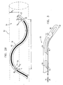
- Fig. 1 illustrates a bend-responsive catheter 20, in accordance with a preferred embodiment of the present invention.
- Catheter 20 includes a distal end 22, which is preferably inserted in the heart of a subject, and a proximal end 24, which is coupled to a control console 26.
- catheter 20 Adjacent to distal end 22, catheter 20 includes a first position-sensing element 28 and, proximal thereto, a second position-sensing element 30, which serves to enable determination of a bending angle of catheter 20, as will be described below.
- each of elements 28 and 30 comprises three substantially orthogonal, non-concentric coils, as described in the above-mentioned PCT publication WO96/05768, which generate signals responsive to magnetic fields applied by field generators 32. These signals are conveyed via wires 34 to signal processing and computing circuitry 36 in console 26, which preferably also provides driver and control signals to generators 32. Circuitry 36 analyzes the signals, as further described in the PCT publication, in order to determine the six-dimensional translational and orientational coordinates of elements 28 and 30 in relation to a frame of reference established by generators 32.
- one of elements 28 and 30 comprise three such coils, and that the other of the elements comprise a single coil, as described in the above-mentioned 5,391,199 patent. As described in the patent, three-dimensional translational coordinates of the single-coil element are determined.
- sensors 28 and 30 may comprise other types and combinations of position sensors, known in the art. It is sufficient, for example, that element 28 be such as to enable determination of three-dimensional translational coordinates and two-dimensional angular elevation and azimuth coordinates with respect thereto, while three-dimensional coordinates are determined with respect to element 30. If bending of catheter 20 is constrained to a plane, as shown in Fig. 2A and described below, it is sufficient to determine two-dimensional coordinates of element 30.
- Catheter 20 preferably includes a resilient longitudinal member 38, for example, a coil spring element, which is fixed within the catheter along a longitudinal axis thereof.
- a resilient longitudinal member 38 for example, a coil spring element, which is fixed within the catheter along a longitudinal axis thereof.
- Such distortion may be caused, for example, by eddy currents induced in the metal parts or by bending of the magnetic field lines by ferromagnetic materials.
- catheter 20 has a generally constant elasticity over at least a portion 40 of its length, preferably extending at least from element 30, or from another point proximal thereto, out to distal end 22, or at least to element 28.
- Portion 40 of catheter 20 is preferably short enough, generally less that about 9 cm long, so that it is inserted entirely into a chamber of the heart with no more than a single bend in the portion. As a result, when portion 40 is bent, whereby element 30 is translationally displaced and orientationally rotated by a known angle relative to element 28, portion 40 will assume an arcuate or helical shape having a known radius of curvature, determined by the known angle.
- Fig. 2A illustrates, for example, a case in which portion 40 of catheter 20 is bent in a plane, which we take to be the plane of the page without loss of generality.
- the length of portion 40 is taken to be L, as shown.
- Respective first and second local coordinate axes 50 (x o ,y o ,z o ) and 52 (x 1 ,y 1 ,z 1 ) are defined at the positions of first and second elements 28 and 30, wherein the local z-axis is taken in every case taken to be aligned with the longitudinal axis of catheter 20, generally parallel to member 38.
- the six-dimensional position coordinates of first element 28 are determined and used to define the element's translational position and first local coordinate axes 50.
- the orientation coordinates of second element 30 define second local axes 52, which together with axes 50 determine a bend angle ⁇ , as shown.
- the elasticity of member 38 ensures that portion 40 will generally follow this arc, so that the position of any point within portion 40 of catheter 20 may be conveniently determined.
- Fig. 2B schematically illustrates the more general case, in which catheter 20 is free to twist in three dimensions.
- portion 40 of catheter 20 has been twisted about its longitudinal axis by approximately 180°, so that axes x 1 and y 1 of second local axes 52 are oriented in generally opposite respective directions to axes x 0 and y 0 of local axes 50.
- the elasticity of member 38 causes portion 40 to assume a generally right-helical form, within the bounds of a cylinder 54 having a diameter R c and length d, as shown in the figure.
- the length d is defined by the translational displacement of element 30 relative to element 28, but determining R c generally requires solving an integral equation.
- solutions to the equation are stored in the form of a look-up table, preferably within signal processing circuitry 36, as is known in the art.
- R c and d then determine the pitch of the helical form, so that the position of any point within portion 40 of catheter 20 may again be conveniently determined.
- portion 40 of catheter 20 will not be allowed to twist by more than 180° in either the clockwise or counterclockwise direction, so that the relative rotational coordinates of elements 28 and 30 will be unambiguous. If necessary, however, the twist of portion 40 may be continuously monitored, by analyzing the signals received from the elements, as catheter 20 is being inserted into and manipulated inside the body, so that rotations of greater than 180° will be detected. These greater twist angles are then used in appropriately determining R c , as described above.
- portion 40 of catheter 20 is free to move.within a body cavity, and that the shape and configuration of portion 40 are determined substantially by its own elasticity. Portion 40 is caused to bend by a combination of a compressive axial force, generally exerted from proximal end 24 of catheter 20 by a user, such as a physician, and a lateral deflecting force exerted on distal end 22 by body tissue with which the distal end is in contact.
- a compressive axial force generally exerted from proximal end 24 of catheter 20 by a user, such as a physician
- a lateral deflecting force exerted on distal end 22 by body tissue with which the distal end is in contact.
- Fig. 3 schematically illustrates an alternative preferred embodiment of the present invention, in which catheter 20 bends controllably, not necessarily in an arcuate or helical form, by means of a steering mechanism 56.
- mechanism 56 comprises an electronically- or mechanically-controlled deflection element, operating under the control of console 26, as described in the above-mentioned PCT patent application no. PCT/IL97/00159.
- mechanism 56 may comprise any suitable catheter steering or deflection device known in the art.
- Catheter 20 is sufficiently rigid, except in an immediate vicinity of mechanism 56, so as to bend only in the immediate vicinity of the mechanism.
- the position coordinates of elements 28 and 30 are used to measure the deflection angle ⁇ , whereby the location of any point along portion 40 of catheter 20 may be determined.
- the measured deflection angle is also used to provide feedback for closed-loop control of mechanism 56.
- Fig. 4 schematically illustrates another preferred embodiment of the present invention, which is similar to the embodiments described above except that in place of second position-sensing element 30, catheter 20 as shown here includes a bend sensor 80, responsive to the angle of bending of the catheter.
- Bend sensor 80 preferably comprises at least one piezoelectric element, or more preferably, three such elements 82, 84 and 86 as shown in the figure.
- the piezoelectric elements are mechanically coupled to resilient member 38, so that when member 38 is bent, as described above, the bending force is conveyed to and acts upon the elements.
- the piezoelectric crystals generate voltage signals that are generally proportional to this bending force, which signals are conveyed by wires 34 to signal processing circuitry 36 in console 26.
- Each of elements 82, 84 and 86 includes a piezoelectric crystal having a crystal axis aligned orthogonally to the axes of the other two elements, so that each crystal generates signals responsive to bending of catheter 20 about a different axis.
- element 82 generates signals responsive to twisting of catheter 20 about its longitudinal axis
- elements 84 and 86 generate signals responsive to left-right and up-down bending, respectively.
- the signals generated by elements 82, 84 and 86 can be used to derive the bend and twist angles of portion 40 of catheter 20. These angles are taken together with the translational and orientational coordinates determined with respect to position-sensing element 28, in order to determine the positions of the plurality of points of interest along the length of catheter 20.
- bend sensors may be used in place of sensor 80 shown in Fig. 4.
- strain gauges may be substituted-for piezoelectric elements 82, 84 and 86.
- Such strain gauges have an electrical resistance that varies as a function of mechanical strain applied thereto, as is known in the art.
- fiberoptic sensors as are known in the art, may be used to determine the bend angle of catheter 20, by measuring the loss and back-reflection of light conveyed through an optical fiber embedded in the catheter.
- additional bend sensors of other types may be positioned at different locations along the length of catheter 20, so that multiple bends or bends of non-constant radius of curvature can be detected.
- catheter 20 may preferably comprise a greater number of position sensors and/or of bend sensors.
- additional sensors may be particularly useful when a portion of the length of the catheter must be tracked within a convoluted passage, or when the catheter is brought to bear against and is desired to conform to a convoluted surface within a body cavity.
- the number of such sensors is held to the minimum needed to achieve the desired accuracy of determination of the plurality of points along the length of the catheter.
- catheter 20 has been shown and described above as comprising only the sensors and other elements necessary for the operation of the present invention, in preferred embodiments of the present invention, the catheter preferably includes other sensing and/or therapeutic devices, as are known in the art.
- the principles of the present invention may then be applied, for example, to map physiological activity or apply local therapeutic treatment within a body cavity, such as a chamber of the heart, with greater ease and accuracy than methods and devices known in the art.
Abstract
Description
- This application claims the benefit of U.S. Provisional Patent Applications no. 60/034,703 and 60/034,704, filed January 3, 1997, which are assigned to the assignee of the present patent application and incorporated herein by reference.
- The present invention relates generally to cardiac diagnostic and therapeutic systems, and specifically to invasive medical probes that may be used to map the interior surfaces of the heart.
- Position-responsive cardiac catheters are known in the art. Such catheters are generally inserted percutaneously and fed through one or more major blood vessels into a chamber of the heart. A position-sensing device in the catheter, typically near the catheter's distal end, gives rise to signals that are used to determine the position of the device (and hence of the catheter) relative to a frame of reference that is fixed either externally to the body or to the heart itself. The position-sensing device may be active or passive and may operate by generating or receiving electrical, magnetic or ultrasonic energy fields or other suitable forms of energy known in the art.
- U.S. patent 5,391,199, which is incorporated herein by reference, describes a position-responsive catheter comprising a miniature sensor coil contained in the catheter's distal end. The coil generates electrical signals in response to externally-applied magnetic fields, which are produced by field-generator coils placed outside the patient's body. The electrical signals are analyzed to determine three-dimensional position coordinates of the coil.
- PCT patent publication number WO96/05768, filed January 24, 1995, which is assigned to the assignee of the present application and whose disclosure is incorporated herein by reference, describes a position-responsive catheter comprising a plurality of miniature, preferably non-concentric sensor coils fixed in its distal end. As in the 5,391,199 patent, electrical signals generated by these coils in response to an externally-applied magnetic field are analyzed so as to determine, in a preferred embodiment, six-dimensional position and orientation coordinates of the coils.
- Multiple position-sensing devices may be placed in a known, mutually-fixed spatial relation at or adjacent to the distal end of a catheter, as described, for example, in PCT patent application no. PCT/IL97/00009, which is assigned to the assignee of the present application and whose disclosure is incorporated herein by reference. This application describes a catheter having a substantially rigid structure at its distal end, to which one or more position sensors are fixed. The sensors are used to determine the position and orientation of the structure, preferably for use in mapping electrical activity in the heart. Although the structure itself is substantially rigid, the remainder of the catheter is generally flexible, and the position sensors do not provide coordinate information regarding any points on the catheter proximal to the structure.
- PCT publication WO95/04938, which is also incorporated herein by reference, describes a miniature magnetic field sensor coil and method of remotely determining the coil's location. The sensor coil may be used to determine the spatial configuration or course of flexible endoscope within the body of a subject in one of two ways: (1) By passing the coil through an internal lumen of the endoscope, for example, the endoscope's biopsy tube, and externally tracking the coil's location while the endoscope is held stationary; or (2) By distributing a plurality of the coils, preferably about a dozen, along the length of the endoscope and determining all of the coils' locations. The position coordinates determined with respect to each location of the coil (when a single coil is used) or to all the coils (when the plurality of coils are used) are taken together to interpolatively reconstruct the spatial configuration of the endoscope within the intestines of the subject, for example, and thereby estimate the corresponding spatial configuration of the intestines.
- The accuracy of this endoscope in estimating the spatial configuration of the intestines depends on having a relatively large number of position measurements and/or of coils. Passing the coil (or other sensor element) through a lumen in the endoscope is time consuming and physically not practical for use in thin probes, such as cardiac catheters that must be passed through blood vessels. Using a large number of coils, however, undesirably increases the weight and cost of the catheter and reduces its flexibility.
- U.S. patent 5,042,486, whose disclosure is further incorporated herein by reference, describes a method of locating a catheter within the body of a subject, generally within a blood vessel, by tracking the position of an electromagnetic or acoustic transmitter or receiver in the tip of the catheter. The position readings are registered with a previously acquired X-ray image of the blood vessel. This method is practical, however, only when the catheter is moving within a vessel or other physiological structure that defines a narrow channel within which the catheter's movement is constrained.
- PCT publication WO 92/03090, whose disclosure is also incorporated herein by reference, describes a probe system, such as an endoscope, including sensing coils mounted at spaced positions along the probe. An array of antennas in a vicinity of the probe are driven by AC electrical signals, so as to induce corresponding voltage signals in the sensing coils. These signals are analyzed to determine three-dimensional coordinates of the coils. The locations of points along the probe, intermediate a pair of the sensing coils, may be determined by interpolation between the respective coordinates of the coils.
- It is an object of the present invention to provide a generally flexible catheter, for insertion into the body of a subject, wherein the course and/or position of the catheter within the body are determined using a minimal number of sensors fixed to the catheter.
- It is a further object of the present invention to provide a catheter having a distal portion that assumes a predetermined shape or curvature, dependent on a force is applied thereto, and a method of determining the course of the distal portion within the body.
- In one aspect of the present invention, the entire course of the distal portion is determined by measuring position coordinates of two points on the portion and using the coordinates to find the shape or curvature of the portion.
- In another aspect of the present invention, the entire course of the distal portion is determined by measuring position coordinates of a point on the portion and measuring the curvature of the portion.
- It is yet another object of the current invention that the course of the catheter may be determined within body cavities in which the catheter is free to move in three dimensions, and not only within constraining lumens as in the prior art.
- In preferred embodiments of the present invention, a flexible catheter, having a distal end for insertion into the body of a subject, comprises first and second sensors, fixed at known, respective positions along a generally distal portion of the length of the catheter, in a known relation to one another and to the distal end. The distal portion of the catheter is sufficiently resilient so as to assume a predetermined, curved form when a force is applied thereto. At least one of the sensors is a position sensor, which generates signals responsive to the position coordinates thereof. The outputs of the first and second sensors are processed jointly to determine the curvature of the portion of the catheter, so as to find the positions of a plurality of points along the length of the distal portion, inside the subject's body.
- Preferably, the at least one position sensor comprises a magnetic-field-responsive coil, as described in the above-mentioned 5,391,199 patent, or more preferably, a plurality of such coils, as described in the above-mentioned PCT publication WO96/05768. The plurality of coils enables six-dimensional position and orientation coordinates to be determined. Alternatively, any suitable position sensor known in the art may be used, such as electrical, magnetic or acoustic sensors.
- In some preferred embodiments of the present invention, both the first and second sensors comprise position sensors, preferably of the type described above with reference to the PCT publication, which allows their six-dimensional coordinates to be determined. The coordinates of the second sensor, relative to those of the first sensor, are determined and taken together with other, known information pertaining to curvature of the catheter. As will be described below, this information is used to find the positions of a plurality of points along the length of the catheter in a vicinity of the first and second sensors.
- In some of these preferred embodiments, the catheter has an elasticity that is generally constant over at least a portion of its length, for example, due to internal reinforcement of the catheter with a resilient longitudinal member, as is known in the art. In this case, absent significant deformation of the catheter due to external forces, the known position and orientation coordinates of the first and second position-sensing elements, determined as described above, are sufficient to establish the curvature of catheter intermediate the elements.
- In other preferred embodiments of the present invention, the first sensor comprises a position sensor, as described above, while the second sensor comprises a bend sensor, which generates signals responsive to a bend radius of the catheter in a vicinity thereof. Preferably, the bend sensor comprises one or more piezoelectric sensors, as are known in the art, which generate electrical signals proportional to a force or torque exerted thereon when the catheter bends. Alternatively, the bend sensor may comprise one or more strain sensors, as are known in the art. Further alternatively, the bend sensor may comprise a fiberoptic sensor fixed in the catheter, wherein the bend radius is determined by measuring the loss and/or back-reflection of light in an optical fiber, as is known in the art.
- Further alternatively, the catheter may include a user-controlled bending mechanism, such as a pull-wire or other mechanism known in the art, or bending mechanisms of other types as described in PCT patent application no. PCT/IL97/00159, which is assigned to the assignee of the present invention, and whose disclosure is incorporated by reference. Preferably, the bending mechanism is calibrated, so that the bend radius of the catheter in a vicinity thereof is known, and is used in determining the positions of the plurality of points along the catheter.
- In some preferred embodiments of the present invention, the catheter includes physiological sensors, such as electrophysiological sensing electrodes, or, additionally or alternatively, therapeutic devices, such as ablation electrodes, at some or all of the plurality of points along its length. Such embodiments are particularly useful, for example, in diagnosis and treatment of abnormal electrical conduction paths in the heart. Devices and methods for use in accordance with these preferred embodiments are further described in U.S. provisional patent application no. 60/034,704 which is assigned to the assignee of the present patent application, and whose disclosure is incorporated herein by reference.
- Although preferred embodiments are described herein with reference to certain types of position and orientation sensors, the principles of the present invention may be implemented in catheters including other types and combinations of such sensors, as are known in the art. It is generally unnecessary to determine six-dimensional position and orientation coordinates of the sensors. It is sufficient, for example, that the first position sensor provide five-dimensional position and orientation data (to determine its three-dimensional translational coordinates and two-dimensional rotational azimuth and elevation), and the second position sensor provide three-dimensional position information. Under these conditions, the positions of the plurality of points along the catheter can be determined, as described above.
- While the preferred embodiments of the present invention are generally described herein with reference to one or two position sensor and/or a single bend sensor, it will be appreciated that the inventive principles that they embody may be similarly applied to catheters, or other probes, having a plurality of position sensors and/or a plurality of bend sensors. Preferably, however, the number of such sensors is held to the minimum needed to achieve the desired accuracy of determination of the plurality of points along the length of the catheter, generally along the portion of the catheter adjacent the distal end thereof.
- Furthermore, although the preferred embodiments described herein make reference to catheters, and particularly to intracardiac catheters, it will be appreciated that the principles of the present invention may similarly be applied to other types of flexible medical probes, such as endoscopes.
- There is therefore provided, in accordance with a preferred embodiment of the present invention, invasive probe apparatus including:
- a flexible, elongate probe, having a distal portion adjacent to a distal end thereof, for insertion into the body of a subject, which portion assumes a predetermined, curved form when a force is applied thereto;
- first and second sensors, fixed to the distal portion of the probe in known positions relative to the distal end, which sensors generate signals responsive to bending of the probe; and
- signal processing circuitry, which receives the bend-responsive signals and processes them to find position and orientation coordinates of at least the first sensor and to determine the locations of a plurality of points along the length of the distal portion of the probe.
- Preferably, the first sensor comprises three coils, which generate signals responsive to an externally-applied magnetic field.
- Preferably, the probe has a generally constant elasticity over the length of the distal portion thereof and includes a resilient longitudinal member.
- In some preferred embodiments of the present invention, the second sensor includes a position-sensing element, and the signal processing circuitry processes the signals generated by the second sensor to find position and orientation coordinates thereof.
- Preferably, the position and orientation coordinates found by the signal processing circuitry include six-dimensional position and orientation coordinates.
- In other preferred embodiments of the present invention, the second sensor includes a bend-sensing element, which generates signals responsive to a direction of bending of the probe.
- Preferably, the bend-sensing element includes at least one piezoelectric crystal, and more preferably, three such crystals, each crystal having an axis, wherein the axes are mutually orthogonal.
- Alternatively, the bend-sensing element includes a fiberoptic sensor or a strain sensor.
- Preferably, the signal processing circuitry determines a radius of curvature of the probe or, alternatively or additionally, a radius and a pitch of a helical form described by the probe.
- Preferably, the probe comprises a deflection device within the distal portion thereof.
- There is further provided, in accordance with a preferred embodiment of the present invention, a method for determining the course of an elongate, flexible probe inside the body of a subject, including:
- finding position and orientation coordinates of a point on the probe;
- measuring a bending angle of a portion of the probe adjacent to the point; and
- processing the position and orientation coordinates and the bending angle to determine the locations of a plurality of points along the length of a portion of the probe inside the body.
- Preferably, finding position and orientation coordinates includes finding six-dimensional position and orientation coordinates.
- Further preferably, measuring a bending angle includes finding position coordinates of an additional point on the probe.
- Alternatively, measuring a bending angle comprises measuring a force associated with bending the probe.
- Preferably, processing the position coordinates and the bending angle includes calculating a radius of curvature of the probe or, alternatively or additionally, calculating a radius of a helical path described by the probe.
- The present invention will be more fully understood from the following detailed description of the preferred embodiments thereof, taken together with the drawings in which:
-
- Fig. 1 is a schematic illustration of a bend-responsive catheter system, in accordance with a preferred embodiment of the present invention;
- Fig. 2A is a schematic illustration of a portion of the catheter shown in Fig. 1, in a first, curved configuration;
- Fig. 2B is a schematic illustration of a portion of the catheter shown in Fig. 1, in a second, twisted configuration;
- Fig. 3 is a schematic illustration showing a bend-responsive catheter, in accordance with another preferred embodiment of the present invention; and
- Fig. 4 is a schematic, partial, sectional illustration showing a bend-responsive catheter, in accordance with another preferred embodiment of the present invention.
- Reference is now made to Fig. 1, which illustrates a bend-
responsive catheter 20, in accordance with a preferred embodiment of the present invention.Catheter 20 includes adistal end 22, which is preferably inserted in the heart of a subject, and aproximal end 24, which is coupled to acontrol console 26. - Adjacent to
distal end 22,catheter 20 includes a first position-sensingelement 28 and, proximal thereto, a second position-sensingelement 30, which serves to enable determination of a bending angle ofcatheter 20, as will be described below. Preferably, each ofelements field generators 32. These signals are conveyed viawires 34 to signal processing andcomputing circuitry 36 inconsole 26, which preferably also provides driver and control signals togenerators 32.Circuitry 36 analyzes the signals, as further described in the PCT publication, in order to determine the six-dimensional translational and orientational coordinates ofelements generators 32. - Alternatively, it is sufficient that one of
elements - Further alternatively,
sensors element 28 be such as to enable determination of three-dimensional translational coordinates and two-dimensional angular elevation and azimuth coordinates with respect thereto, while three-dimensional coordinates are determined with respect toelement 30. If bending ofcatheter 20 is constrained to a plane, as shown in Fig. 2A and described below, it is sufficient to determine two-dimensional coordinates ofelement 30. -
Catheter 20 preferably includes a resilientlongitudinal member 38, for example, a coil spring element, which is fixed within the catheter along a longitudinal axis thereof. Preferably, there is a sufficient distance between metal parts ofmember 38 andsensors member 38,catheter 20 has a generally constant elasticity over at least aportion 40 of its length, preferably extending at least fromelement 30, or from another point proximal thereto, out todistal end 22, or at least toelement 28.Portion 40 ofcatheter 20 is preferably short enough, generally less that about 9 cm long, so that it is inserted entirely into a chamber of the heart with no more than a single bend in the portion. As a result, whenportion 40 is bent, wherebyelement 30 is translationally displaced and orientationally rotated by a known angle relative toelement 28,portion 40 will assume an arcuate or helical shape having a known radius of curvature, determined by the known angle. - Fig. 2A illustrates, for example, a case in which
portion 40 ofcatheter 20 is bent in a plane, which we take to be the plane of the page without loss of generality. The length ofportion 40 is taken to be L, as shown. Respective first and second local coordinate axes 50 (xo,yo,zo) and 52 (x1,y1,z1) are defined at the positions of first andsecond elements catheter 20, generally parallel tomember 38. - The six-dimensional position coordinates of
first element 28 are determined and used to define the element's translational position and first local coordinateaxes 50. The orientation coordinates ofsecond element 30 define secondlocal axes 52, which together withaxes 50 determine a bend angle θ, as shown. An arc is thus defined having a radius of curvature given by R = L/θ, and a center ofcurvature 54 at a position y=R defined with respect to coordinateaxes member 38 ensures thatportion 40 will generally follow this arc, so that the position of any point withinportion 40 ofcatheter 20 may be conveniently determined. - Fig. 2B schematically illustrates the more general case, in which
catheter 20 is free to twist in three dimensions. In the case shown here,portion 40 ofcatheter 20 has been twisted about its longitudinal axis by approximately 180°, so that axes x1 and y1 of secondlocal axes 52 are oriented in generally opposite respective directions to axes x0 and y0 oflocal axes 50. The elasticity ofmember 38 causesportion 40 to assume a generally right-helical form, within the bounds of acylinder 54 having a diameter Rc and length d, as shown in the figure. The length d is defined by the translational displacement ofelement 30 relative toelement 28, but determining Rc generally requires solving an integral equation. Preferably, solutions to the equation are stored in the form of a look-up table, preferably withinsignal processing circuitry 36, as is known in the art. Rc and d then determine the pitch of the helical form, so that the position of any point withinportion 40 ofcatheter 20 may again be conveniently determined. - Preferably,
portion 40 ofcatheter 20 will not be allowed to twist by more than 180° in either the clockwise or counterclockwise direction, so that the relative rotational coordinates ofelements portion 40 may be continuously monitored, by analyzing the signals received from the elements, ascatheter 20 is being inserted into and manipulated inside the body, so that rotations of greater than 180° will be detected. These greater twist angles are then used in appropriately determining Rc, as described above. - In the preferred embodiments described above, it is assumed that
portion 40 ofcatheter 20 is free to move.within a body cavity, and that the shape and configuration ofportion 40 are determined substantially by its own elasticity.Portion 40 is caused to bend by a combination of a compressive axial force, generally exerted fromproximal end 24 ofcatheter 20 by a user, such as a physician, and a lateral deflecting force exerted ondistal end 22 by body tissue with which the distal end is in contact. - Fig. 3 schematically illustrates an alternative preferred embodiment of the present invention, in which
catheter 20 bends controllably, not necessarily in an arcuate or helical form, by means of asteering mechanism 56. Preferably,mechanism 56 comprises an electronically- or mechanically-controlled deflection element, operating under the control ofconsole 26, as described in the above-mentioned PCT patent application no. PCT/IL97/00159. Alternatively,mechanism 56 may comprise any suitable catheter steering or deflection device known in the art.Catheter 20 is sufficiently rigid, except in an immediate vicinity ofmechanism 56, so as to bend only in the immediate vicinity of the mechanism. The position coordinates ofelements portion 40 ofcatheter 20 may be determined. Preferably, the measured deflection angle is also used to provide feedback for closed-loop control ofmechanism 56. - Fig. 4 schematically illustrates another preferred embodiment of the present invention, which is similar to the embodiments described above except that in place of second position-sensing
element 30,catheter 20 as shown here includes abend sensor 80, responsive to the angle of bending of the catheter.Bend sensor 80 preferably comprises at least one piezoelectric element, or more preferably, threesuch elements resilient member 38, so that whenmember 38 is bent, as described above, the bending force is conveyed to and acts upon the elements. As is known in the art, the piezoelectric crystals generate voltage signals that are generally proportional to this bending force, which signals are conveyed bywires 34 to signalprocessing circuitry 36 inconsole 26. - Each of
elements catheter 20 about a different axis. Thus, as shown in Fig. 4,element 82 generates signals responsive to twisting ofcatheter 20 about its longitudinal axis, andelements - Due to the generally constant elasticity of
member 38, the signals generated byelements portion 40 ofcatheter 20. These angles are taken together with the translational and orientational coordinates determined with respect to position-sensingelement 28, in order to determine the positions of the plurality of points of interest along the length ofcatheter 20. - Other types of bend sensors may be used in place of
sensor 80 shown in Fig. 4. For example, strain gauges may be substituted-forpiezoelectric elements catheter 20, by measuring the loss and back-reflection of light conveyed through an optical fiber embedded in the catheter. - Furthermore, additional bend sensors of other types may be positioned at different locations along the length of
catheter 20, so that multiple bends or bends of non-constant radius of curvature can be detected. - More generally speaking, while the preferred embodiments of the present invention have been described above with reference to one or two position-
sensing elements single bend sensor 80, it will be appreciated that for some applications,catheter 20 may preferably comprise a greater number of position sensors and/or of bend sensors. Such additional sensors may be particularly useful when a portion of the length of the catheter must be tracked within a convoluted passage, or when the catheter is brought to bear against and is desired to conform to a convoluted surface within a body cavity. Preferably, however, the number of such sensors is held to the minimum needed to achieve the desired accuracy of determination of the plurality of points along the length of the catheter. - Although for simplicity of illustration,
catheter 20 has been shown and described above as comprising only the sensors and other elements necessary for the operation of the present invention, in preferred embodiments of the present invention, the catheter preferably includes other sensing and/or therapeutic devices, as are known in the art. The principles of the present invention may then be applied, for example, to map physiological activity or apply local therapeutic treatment within a body cavity, such as a chamber of the heart, with greater ease and accuracy than methods and devices known in the art. - It will be appreciated that the principles of the present invention may be applied, as well, to other flexible medical probes, such as endoscopes.
- It will further be appreciated that the preferred embodiments described above are cited by way of example, and the full scope of the invention is limited only by the claims.
- Additional statements of invention:
- 1. Invasive probe apparatus comprising:
- a flexible, elongate probe, having a distal portion adjacent to a distal end thereof, for insertion into the body of a subject, which portion assumes a predetermined, curved form when a force is applied thereto;
- first and second sensors, fixed to the distal portion of the probe in known positions relative to the distal end, which sensors generate signals responsive to bending of the probe; and
- signal processing circuitry, which receives the bend-responsive signals and processes them to find position and orientation coordinates of at least the first sensor and to determine the locations of a plurality of points along the length of the distal portion of the probe.
- 2. Apparatus according to clause 1, wherein the first sensor comprises three coils, which generate signals responsive to an externally-applied magnetic field.
- 3. Apparatus according to clause 1, wherein the probe has a generally constant elasticity over the length of the distal portion thereof.
- 4. Apparatus according to clause 1, wherein the probe comprises a resilient longitudinal member.
- 5. Apparatus according to any of the preceding clauses, wherein the second sensor comprises a position-sensing element.
- 6. Apparatus according to clause 5, wherein the signal processing circuitry processes the signals generated by the second sensor to find position and orientation coordinates thereof.
- 7. Apparatus according to any of clauses 1-4, wherein the position and orientation coordinates found by the signal processing circuitry comprise six-dimensional position and orientation coordinates.
- 8. Apparatus according to any of clauses 1-4, wherein the second sensor comprises a bend-sensing element.
- 9. Apparatus according to clause 8, wherein the bend-sensing element generates signals responsive to a direction of bending of the probe.
- 10. Apparatus according to clause 8, wherein the bend-sensing element comprises at least one piezoelectric crystal.
- 11. Apparatus according to clause 10, wherein the at least one piezoelectric crystal comprises three such crystals, each crystal having an axis, wherein the axes are mutually orthogonal.
- 12. Apparatus according to clause 8, wherein the bend-sensing element comprises a fiberoptic sensor.
- 13. Apparatus according to clause 8, wherein the bend-sensing element comprises a strain sensor.
- 14. Apparatus according to any of clauses 1-4, wherein the signal processing circuitry determines a radius of curvature of the probe.
- 15. Apparatus according to any clauses 1-4, wherein the signal processing circuitry determines a radius and a pitch of a helical form described by the probe.
- 16. Apparatus according to any of clauses 1-4, wherein the probe comprises a deflection device within the distal portion thereof.
- 17. A method for determining the course of an elongate, flexible probe inside the body of a subject, comprising:
- finding position and orientation coordinates of a point on the probe;
- measuring a bending angle of a portion of the probe adjacent to the point; and
- processing the position and orientation coordinates and the bending angle to determine the locations of a plurality of points along the length of a portion of the probe inside the body.
- 18. A method according to clause 17, wherein finding position and orientation coordinates comprises finding six-dimensional position and orientation coordinates.
- 19. A method according to clause 17, wherein measuring a bending angle comprises finding position coordinates of an additional point on the probe.
- 20. A method according to clause 17, wherein measuring a bending angle comprises measuring a force associated with bending the probe.
- 21. A method according to any of clauses 17-20, wherein processing the position coordinates and the bending angle comprises calculating a radius of curvature of the probe.
- 22. A method according to any of clauses 17-20, wherein processing the position coordinates and the bending angle comprises calculating a radius of a helical path described by the probe.
Claims (12)
- Invasive probe apparatus for use with an externally-applied magnetic field, the probe comprising:a flexible, elongate probe, having a distal portion adjacent to a distal end thereof, for insertion into the body of a subject, which portion assumes a predetermined, curved form when a force is applied thereto;a first sensor and a second sensor, fixed to the distal portion of the probe in known positions relative to the distal end, which sensors generate signals, the first sensor being a magnetic-field responsive sensor as a first position-sensing element for generating a first signal to enable determination of position and orientation coordinates of the first position-sensing element, said first signal defining a position and orientation coordinate signal, and the second sensor being a force-sensitive bend-sensing element for generating a second signal responsive to a force exerted in bending of the probe, said second signal defining a bend signal; andsignal processing circuitry, which receives the position and orientation coordinate signal and the bend signal and processes them to find position and orientation coordinates of at least the first sensor and to determine the locations of a plurality of points along the length of the distal portion of the probe.
- Apparatus according to claim 1, wherein the first sensor comprises three coils, which generate signals responsive to the externally-applied magnetic field.
- Apparatus according to claim 1 or claim 2, wherein the probe has a generally constant elasticity over the length of the distal portion thereof.
- Apparatus according to claim 1, claim 2 or claim 3, wherein the probe comprises a resilient longitudinal member.
- Apparatus according to claim 4, wherein the bend-sensing element generates signals responsive to a direction of bending of the probe.
- Apparatus according to claim 4 or claim 5, wherein the bend-sensing element comprises at least one piezoelectric crystal.
- Apparatus according to claim 6, wherein the at least one piezoelectric crystal comprises three such crystals, each crystal having an axis, wherein the axes are mutually orthogonal.
- Apparatus according to any one of claims 4 to 7, wherein the bend-sensing element comprises a fiberoptic sensor.
- Apparatus according to any one of claims 4 to 8, wherein the bend-sensing element comprises a strain sensor.
- Apparatus according to any one of claims 4 to 9, wherein the probe comprises a deflection device within the distal portion thereof.
- Apparatus according to any one of the preceding claims, wherein the signal processing circuitry determines a radius of curvature of the probe.
- Apparatus according to any one of claims 1 to 10, wherein the signal processing circuitry determines a radius and a pitch of a helical form described by the probe.
Applications Claiming Priority (6)
| Application Number | Priority Date | Filing Date | Title |
|---|---|---|---|
| US3470397P | 1997-01-03 | 1997-01-03 | |
| US3470497P | 1997-01-03 | 1997-01-03 | |
| US34704P | 1997-01-03 | ||
| US34703P | 1997-01-03 | ||
| US09/125,932 US6272371B1 (en) | 1997-01-03 | 1997-12-31 | Bend-responsive catheter |
| EP97950367A EP0901341B1 (en) | 1997-01-03 | 1997-12-31 | Bend-responsive catheter |
Related Parent Applications (2)
| Application Number | Title | Priority Date | Filing Date |
|---|---|---|---|
| EP97950367A Division EP0901341B1 (en) | 1997-01-03 | 1997-12-31 | Bend-responsive catheter |
| EP97950367.9 Division | 1998-07-09 |
Publications (3)
| Publication Number | Publication Date |
|---|---|
| EP1491139A2 true EP1491139A2 (en) | 2004-12-29 |
| EP1491139A3 EP1491139A3 (en) | 2005-06-01 |
| EP1491139B1 EP1491139B1 (en) | 2007-08-29 |
Family
ID=37801429
Family Applications (1)
| Application Number | Title | Priority Date | Filing Date |
|---|---|---|---|
| EP04077532A Expired - Lifetime EP1491139B1 (en) | 1997-01-03 | 1997-12-31 | Bend-responsive catheter |
Country Status (3)
| Country | Link |
|---|---|
| US (1) | US6272371B1 (en) |
| EP (1) | EP1491139B1 (en) |
| SI (1) | SI0901341T1 (en) |
Cited By (12)
| Publication number | Priority date | Publication date | Assignee | Title |
|---|---|---|---|---|
| WO2008045956A2 (en) * | 2006-10-12 | 2008-04-17 | St. Jude Medical, Atrial Fibrillation Division, Inc. | Tissue contact and thermal assessment for brush electrodes |
| WO2008045958A2 (en) * | 2006-10-12 | 2008-04-17 | St. Jude Medical, Atrial Fibrillation Division, Inc. | Systems and methods for assessing tissue contact |
| DE102008013429A1 (en) * | 2008-03-10 | 2009-10-01 | Siemens Aktiengesellschaft | Device for contacting region of e.g. tissue, of animal for e.g. therapeutic treatment, has sensor arranged at distal end of medical instrument near to surface or at surface of instrument for registering force acting on instrument |
| US7883508B2 (en) | 2006-12-29 | 2011-02-08 | St. Jude Medical, Atrial Fibrillation Division, Inc. | Contact-sensitive pressure-sensitive conductive composite electrode and method for ablation |
| US7955326B2 (en) | 2006-12-29 | 2011-06-07 | St. Jude Medical, Atrial Fibrillation Division, Inc. | Pressure-sensitive conductive composite electrode and method for ablation |
| US8021361B2 (en) | 2005-10-27 | 2011-09-20 | St. Jude Medical, Atrial Fibrillation Division, Inc. | Systems and methods for electrode contact assessment |
| US8679109B2 (en) | 2005-10-13 | 2014-03-25 | St. Jude Medical, Atrial Fibrillation Division, Inc. | Dynamic contact assessment for electrode catheters |
| US9949792B2 (en) | 2006-12-29 | 2018-04-24 | St. Jude Medical, Atrial Fibrillation Division, Inc. | Pressure-sensitive flexible polymer bipolar electrode |
| US10085798B2 (en) | 2006-12-29 | 2018-10-02 | St. Jude Medical, Atrial Fibrillation Division, Inc. | Ablation electrode with tactile sensor |
| KR20190101860A (en) * | 2016-12-28 | 2019-09-02 | 아우리스 헬스, 인코포레이티드 | Device for inserting flexible instruments |
| EP3569173A1 (en) * | 2018-05-17 | 2019-11-20 | VascoMed GmbH | Catheter and system |
| US11771309B2 (en) | 2016-12-28 | 2023-10-03 | Auris Health, Inc. | Detecting endolumenal buckling of flexible instruments |
Families Citing this family (247)
| Publication number | Priority date | Publication date | Assignee | Title |
|---|---|---|---|---|
| US6625482B1 (en) * | 1998-03-06 | 2003-09-23 | Ep Technologies, Inc. | Graphical user interface for use with multiple electrode catheters |
| US8000764B2 (en) * | 1997-06-20 | 2011-08-16 | St. Jude Medical, Atrial Fibrillation Division, Inc. | Electrophysiology/ablation catheter having second passage |
| US20030109778A1 (en) * | 1997-06-20 | 2003-06-12 | Cardiac Assist Devices, Inc. | Electrophysiology/ablation catheter and remote actuator therefor |
| SE9704312D0 (en) * | 1997-11-24 | 1997-11-24 | Pacesetter Ab | Sensing of heart contraction |
| US7713190B2 (en) | 1998-02-24 | 2010-05-11 | Hansen Medical, Inc. | Flexible instrument |
| US20030074011A1 (en) * | 1998-09-24 | 2003-04-17 | Super Dimension Ltd. | System and method of recording and displaying in context of an image a location of at least one point-of-interest in a body during an intra-body medical procedure |
| US6626899B2 (en) | 1999-06-25 | 2003-09-30 | Nidus Medical, Llc | Apparatus and methods for treating tissue |
| US6394986B1 (en) | 1999-11-06 | 2002-05-28 | Millar Instruments, Inc. | Pressure sensing module for a catheter pressure transducer |
| US6892091B1 (en) * | 2000-02-18 | 2005-05-10 | Biosense, Inc. | Catheter, method and apparatus for generating an electrical map of a chamber of the heart |
| US7194296B2 (en) * | 2000-10-31 | 2007-03-20 | Northern Digital Inc. | Flexible instrument with optical sensors |
| US8414505B1 (en) | 2001-02-15 | 2013-04-09 | Hansen Medical, Inc. | Catheter driver system |
| US7699835B2 (en) * | 2001-02-15 | 2010-04-20 | Hansen Medical, Inc. | Robotically controlled surgical instruments |
| US7766894B2 (en) | 2001-02-15 | 2010-08-03 | Hansen Medical, Inc. | Coaxial catheter system |
| US20020116028A1 (en) * | 2001-02-20 | 2002-08-22 | Wilson Greatbatch | MRI-compatible pacemaker with pulse carrying photonic catheter providing VOO functionality |
| US6785571B2 (en) * | 2001-03-30 | 2004-08-31 | Neil David Glossop | Device and method for registering a position sensor in an anatomical body |
| US7018346B2 (en) | 2001-12-18 | 2006-03-28 | Scimed Life Systems, Inc. | Guide wire with adjustable flexibility |
| US7277833B2 (en) * | 2002-02-06 | 2007-10-02 | Siemens Corporate Research, Inc. | Modeling of the workspace and active pending behavior of an endscope using filter functions |
| US6976967B2 (en) * | 2002-02-19 | 2005-12-20 | Medtronic, Inc. | Apparatus and method for sensing spatial displacement in a heart |
| US7378048B2 (en) * | 2002-12-03 | 2008-05-27 | Boston Scientific Scimed, Inc. | Method for forming catheter curves |
| US7451658B2 (en) * | 2003-01-07 | 2008-11-18 | Sensopad Limited | Sensing apparatus and method |
| US8007511B2 (en) | 2003-06-06 | 2011-08-30 | Hansen Medical, Inc. | Surgical instrument design |
| US6973339B2 (en) * | 2003-07-29 | 2005-12-06 | Biosense, Inc | Lasso for pulmonary vein mapping and ablation |
| US7758587B2 (en) * | 2003-10-08 | 2010-07-20 | Boston Scientific Scimed, Inc. | Medical device guidance from an anatomical reference |
| US7340960B2 (en) * | 2004-01-30 | 2008-03-11 | Analatom Inc. | Miniature sensor |
| CA2555473A1 (en) | 2004-02-17 | 2005-09-01 | Traxtal Technologies Inc. | Method and apparatus for registration, verification, and referencing of internal organs |
| US7976539B2 (en) | 2004-03-05 | 2011-07-12 | Hansen Medical, Inc. | System and method for denaturing and fixing collagenous tissue |
| EP1720480A1 (en) | 2004-03-05 | 2006-11-15 | Hansen Medical, Inc. | Robotic catheter system |
| US10863945B2 (en) | 2004-05-28 | 2020-12-15 | St. Jude Medical, Atrial Fibrillation Division, Inc. | Robotic surgical system with contact sensing feature |
| US8528565B2 (en) | 2004-05-28 | 2013-09-10 | St. Jude Medical, Atrial Fibrillation Division, Inc. | Robotic surgical system and method for automated therapy delivery |
| US10258285B2 (en) | 2004-05-28 | 2019-04-16 | St. Jude Medical, Atrial Fibrillation Division, Inc. | Robotic surgical system and method for automated creation of ablation lesions |
| US8755864B2 (en) | 2004-05-28 | 2014-06-17 | St. Jude Medical, Atrial Fibrillation Division, Inc. | Robotic surgical system and method for diagnostic data mapping |
| US9782130B2 (en) | 2004-05-28 | 2017-10-10 | St. Jude Medical, Atrial Fibrillation Division, Inc. | Robotic surgical system |
| US7974674B2 (en) | 2004-05-28 | 2011-07-05 | St. Jude Medical, Atrial Fibrillation Division, Inc. | Robotic surgical system and method for surface modeling |
| US7632265B2 (en) | 2004-05-28 | 2009-12-15 | St. Jude Medical, Atrial Fibrillation Division, Inc. | Radio frequency ablation servo catheter and method |
| US20090216115A1 (en) * | 2004-07-23 | 2009-08-27 | Calypso Medical Technologies, Inc. | Anchoring wirless markers within a human body |
| IL170404A (en) * | 2004-08-26 | 2012-03-29 | C2Cure Inc | Wireless determination of endoscope orientation |
| US7722565B2 (en) | 2004-11-05 | 2010-05-25 | Traxtal, Inc. | Access system |
| KR100689707B1 (en) * | 2004-11-12 | 2007-03-08 | 삼성전자주식회사 | Bank selection signal control circuit, semiconductor memory device having the same and method for control bank selection signal |
| US7805269B2 (en) | 2004-11-12 | 2010-09-28 | Philips Electronics Ltd | Device and method for ensuring the accuracy of a tracking device in a volume |
| US7751868B2 (en) | 2004-11-12 | 2010-07-06 | Philips Electronics Ltd | Integrated skin-mounted multifunction device for use in image-guided surgery |
| US7828790B2 (en) | 2004-12-03 | 2010-11-09 | Boston Scientific Scimed, Inc. | Selectively flexible catheter and method of use |
| US8611983B2 (en) | 2005-01-18 | 2013-12-17 | Philips Electronics Ltd | Method and apparatus for guiding an instrument to a target in the lung |
| EP1838215B1 (en) | 2005-01-18 | 2012-08-01 | Philips Electronics LTD | Electromagnetically tracked k-wire device |
| US8182433B2 (en) * | 2005-03-04 | 2012-05-22 | Endosense Sa | Medical apparatus system having optical fiber load sensing capability |
| US8075498B2 (en) | 2005-03-04 | 2011-12-13 | Endosense Sa | Medical apparatus system having optical fiber load sensing capability |
| US8155910B2 (en) | 2005-05-27 | 2012-04-10 | St. Jude Medical, Atrial Fibrillation Divison, Inc. | Robotically controlled catheter and method of its calibration |
| CA2612603C (en) | 2005-06-21 | 2015-05-19 | Traxtal Inc. | Device and method for a trackable ultrasound |
| EP1898775B1 (en) | 2005-06-21 | 2013-02-13 | Philips Electronics LTD | System and apparatus for navigated therapy and diagnosis |
| EP1906858B1 (en) | 2005-07-01 | 2016-11-16 | Hansen Medical, Inc. | Robotic catheter system |
| US8894589B2 (en) | 2005-08-01 | 2014-11-25 | Endosense Sa | Medical apparatus system having optical fiber load sensing capability |
| US9661991B2 (en) | 2005-08-24 | 2017-05-30 | Koninklijke Philips N.V. | System, method and devices for navigated flexible endoscopy |
| US8784336B2 (en) | 2005-08-24 | 2014-07-22 | C. R. Bard, Inc. | Stylet apparatuses and methods of manufacture |
| US8116886B2 (en) * | 2005-10-14 | 2012-02-14 | The Trustees Of Columbia University In The City Of New York | Electrode arrays and systems for inserting same |
| US20070106114A1 (en) * | 2005-11-09 | 2007-05-10 | Pentax Corporation | Endoscope-shape monitoring system |
| US20090216113A1 (en) | 2005-11-17 | 2009-08-27 | Eric Meier | Apparatus and Methods for Using an Electromagnetic Transponder in Orthopedic Procedures |
| EP3788944B1 (en) | 2005-11-22 | 2024-02-28 | Intuitive Surgical Operations, Inc. | System for determining the shape of a bendable instrument |
| CN102599875B (en) * | 2006-03-22 | 2015-03-11 | 皇家飞利浦电子股份有限公司 | Medical instrument system |
| JP4878513B2 (en) * | 2006-03-27 | 2012-02-15 | 国立大学法人 名古屋工業大学 | Apparatus and method for measuring compressive force of flexible linear body |
| US8567265B2 (en) | 2006-06-09 | 2013-10-29 | Endosense, SA | Triaxial fiber optic force sensing catheter |
| US8048063B2 (en) * | 2006-06-09 | 2011-11-01 | Endosense Sa | Catheter having tri-axial force sensor |
| US20080097501A1 (en) * | 2006-06-22 | 2008-04-24 | Tyco Healthcare Group Lp | Ultrasonic probe deflection sensor |
| DE102006029122A1 (en) * | 2006-06-22 | 2007-12-27 | Amedo Gmbh | System for determining the position of a medical instrument |
| GB2441306A (en) * | 2006-09-01 | 2008-03-05 | Microsulis Ltd | Endometrial treatment device with stepper actuator, angular sweep rate sensor and bending deflection sensor |
| JP4878526B2 (en) * | 2006-09-05 | 2012-02-15 | 国立大学法人 名古屋工業大学 | Apparatus for measuring compressive force of flexible linear body |
| US7794407B2 (en) | 2006-10-23 | 2010-09-14 | Bard Access Systems, Inc. | Method of locating the tip of a central venous catheter |
| US8388546B2 (en) | 2006-10-23 | 2013-03-05 | Bard Access Systems, Inc. | Method of locating the tip of a central venous catheter |
| US7892165B2 (en) * | 2006-10-23 | 2011-02-22 | Hoya Corporation | Camera calibration for endoscope navigation system |
| US9579483B2 (en) | 2006-12-29 | 2017-02-28 | St. Jude Medical, Atrial Fibrillation Division, Inc. | Pressure-sensitive conductive composite contact sensor and method for contact sensing |
| EP1970001B1 (en) * | 2007-03-16 | 2014-07-23 | Brainlab AG | Catheter with pressure sensoring |
| JP5177352B2 (en) * | 2007-04-10 | 2013-04-03 | 国立大学法人 名古屋工業大学 | Linear body drive device |
| US8050523B2 (en) * | 2007-04-20 | 2011-11-01 | Koninklijke Philips Electronics N.V. | Optical fiber shape sensing systems |
| US8157789B2 (en) * | 2007-05-24 | 2012-04-17 | Endosense Sa | Touch sensing catheter |
| US8622935B1 (en) | 2007-05-25 | 2014-01-07 | Endosense Sa | Elongated surgical manipulator with body position and distal force sensing |
| US20130165945A9 (en) * | 2007-08-14 | 2013-06-27 | Hansen Medical, Inc. | Methods and devices for controlling a shapeable instrument |
| US8357152B2 (en) * | 2007-10-08 | 2013-01-22 | Biosense Webster (Israel), Ltd. | Catheter with pressure sensing |
| US8535308B2 (en) * | 2007-10-08 | 2013-09-17 | Biosense Webster (Israel), Ltd. | High-sensitivity pressure-sensing probe |
| US10524691B2 (en) | 2007-11-26 | 2020-01-07 | C. R. Bard, Inc. | Needle assembly including an aligned magnetic element |
| US8388541B2 (en) | 2007-11-26 | 2013-03-05 | C. R. Bard, Inc. | Integrated system for intravascular placement of a catheter |
| US10751509B2 (en) | 2007-11-26 | 2020-08-25 | C. R. Bard, Inc. | Iconic representations for guidance of an indwelling medical device |
| US10449330B2 (en) | 2007-11-26 | 2019-10-22 | C. R. Bard, Inc. | Magnetic element-equipped needle assemblies |
| US8781555B2 (en) | 2007-11-26 | 2014-07-15 | C. R. Bard, Inc. | System for placement of a catheter including a signal-generating stylet |
| US8849382B2 (en) | 2007-11-26 | 2014-09-30 | C. R. Bard, Inc. | Apparatus and display methods relating to intravascular placement of a catheter |
| US9649048B2 (en) | 2007-11-26 | 2017-05-16 | C. R. Bard, Inc. | Systems and methods for breaching a sterile field for intravascular placement of a catheter |
| US9521961B2 (en) * | 2007-11-26 | 2016-12-20 | C. R. Bard, Inc. | Systems and methods for guiding a medical instrument |
| US8478382B2 (en) | 2008-02-11 | 2013-07-02 | C. R. Bard, Inc. | Systems and methods for positioning a catheter |
| US20110066160A1 (en) * | 2008-04-03 | 2011-03-17 | The Trustees Of Columbia University In The City Of New York | Systems and methods for inserting steerable arrays into anatomical structures |
| WO2009122273A2 (en) | 2008-04-03 | 2009-10-08 | Superdimension, Ltd. | Magnetic interference detection system and method |
| US8298227B2 (en) * | 2008-05-14 | 2012-10-30 | Endosense Sa | Temperature compensated strain sensing catheter |
| JP5334035B2 (en) * | 2008-05-29 | 2013-11-06 | Ntn株式会社 | Coil insertion device |
| EP2297673B1 (en) | 2008-06-03 | 2020-04-22 | Covidien LP | Feature-based registration method |
| US8437832B2 (en) * | 2008-06-06 | 2013-05-07 | Biosense Webster, Inc. | Catheter with bendable tip |
| US8218847B2 (en) | 2008-06-06 | 2012-07-10 | Superdimension, Ltd. | Hybrid registration method |
| US8290571B2 (en) * | 2008-08-01 | 2012-10-16 | Koninklijke Philips Electronics N.V. | Auxiliary cavity localization |
| US8926528B2 (en) * | 2008-08-06 | 2015-01-06 | Biosense Webster, Inc. | Single-axis sensors on flexible backbone |
| US9901714B2 (en) | 2008-08-22 | 2018-02-27 | C. R. Bard, Inc. | Catheter assembly including ECG sensor and magnetic assemblies |
| US9101734B2 (en) * | 2008-09-09 | 2015-08-11 | Biosense Webster, Inc. | Force-sensing catheter with bonded center strut |
| US8437833B2 (en) | 2008-10-07 | 2013-05-07 | Bard Access Systems, Inc. | Percutaneous magnetic gastrostomy |
| US8594799B2 (en) * | 2008-10-31 | 2013-11-26 | Advanced Bionics | Cochlear electrode insertion |
| US9326700B2 (en) * | 2008-12-23 | 2016-05-03 | Biosense Webster (Israel) Ltd. | Catheter display showing tip angle and pressure |
| US8475450B2 (en) * | 2008-12-30 | 2013-07-02 | Biosense Webster, Inc. | Dual-purpose lasso catheter with irrigation |
| US8600472B2 (en) | 2008-12-30 | 2013-12-03 | Biosense Webster (Israel), Ltd. | Dual-purpose lasso catheter with irrigation using circumferentially arranged ring bump electrodes |
| US9943704B1 (en) | 2009-01-21 | 2018-04-17 | Varian Medical Systems, Inc. | Method and system for fiducials contained in removable device for radiation therapy |
| US9254123B2 (en) | 2009-04-29 | 2016-02-09 | Hansen Medical, Inc. | Flexible and steerable elongate instruments with shape control and support elements |
| EP2440130A4 (en) | 2009-06-08 | 2015-06-03 | Mri Interventions Inc | Mri-guided surgical systems with proximity alerts |
| US9532724B2 (en) | 2009-06-12 | 2017-01-03 | Bard Access Systems, Inc. | Apparatus and method for catheter navigation using endovascular energy mapping |
| EP3542713A1 (en) | 2009-06-12 | 2019-09-25 | Bard Access Systems, Inc. | Adapter for a catheter tip positioning device |
| US8396532B2 (en) | 2009-06-16 | 2013-03-12 | MRI Interventions, Inc. | MRI-guided devices and MRI-guided interventional systems that can track and generate dynamic visualizations of the devices in near real time |
| US10080482B2 (en) * | 2009-06-30 | 2018-09-25 | Intuitive Surgical Operations, Inc. | Compliant surgical device |
| WO2011019760A2 (en) | 2009-08-10 | 2011-02-17 | Romedex International Srl | Devices and methods for endovascular electrography |
| EP2517622A3 (en) | 2009-09-29 | 2013-04-24 | C. R. Bard, Inc. | Stylets for use with apparatus for intravascular placement of a catheter |
| US11103213B2 (en) | 2009-10-08 | 2021-08-31 | C. R. Bard, Inc. | Spacers for use with an ultrasound probe |
| JP5819836B2 (en) * | 2009-10-22 | 2015-11-24 | レメンディウム ラブズ リミテッド ライアビリティ カンパニー | Treatment of stress urinary incontinence in women |
| WO2011053766A1 (en) * | 2009-10-30 | 2011-05-05 | Advanced Bionics, Llc | Steerable stylet |
| US20110118590A1 (en) * | 2009-11-18 | 2011-05-19 | Siemens Medical Solutions Usa, Inc. | System For Continuous Cardiac Imaging And Mapping |
| US10688278B2 (en) | 2009-11-30 | 2020-06-23 | Biosense Webster (Israel), Ltd. | Catheter with pressure measuring tip |
| US9861438B2 (en) * | 2009-12-11 | 2018-01-09 | Biosense Webster (Israel), Ltd. | Pre-formed curved ablation catheter |
| US8920415B2 (en) | 2009-12-16 | 2014-12-30 | Biosense Webster (Israel) Ltd. | Catheter with helical electrode |
| US8926604B2 (en) * | 2009-12-23 | 2015-01-06 | Biosense Webster (Israel) Ltd. | Estimation and mapping of ablation volume |
| US8521462B2 (en) | 2009-12-23 | 2013-08-27 | Biosense Webster (Israel), Ltd. | Calibration system for a pressure-sensitive catheter |
| US9962217B2 (en) | 2009-12-23 | 2018-05-08 | Biosense Webster (Israel) Ltd. | Estimation and mapping of ablation volume |
| US8529476B2 (en) * | 2009-12-28 | 2013-09-10 | Biosense Webster (Israel), Ltd. | Catheter with strain gauge sensor |
| US8608735B2 (en) * | 2009-12-30 | 2013-12-17 | Biosense Webster (Israel) Ltd. | Catheter with arcuate end section |
| US8374670B2 (en) * | 2010-01-22 | 2013-02-12 | Biosense Webster, Inc. | Catheter having a force sensing distal tip |
| CN102821679B (en) | 2010-02-02 | 2016-04-27 | C·R·巴德股份有限公司 | For the apparatus and method that catheter navigation and end are located |
| JP5980201B2 (en) | 2010-05-28 | 2016-08-31 | シー・アール・バード・インコーポレーテッドC R Bard Incorporated | Insertion guidance system for needles and medical components |
| WO2011150376A1 (en) | 2010-05-28 | 2011-12-01 | C.R. Bard, Inc. | Apparatus for use with needle insertion guidance system |
| US8798952B2 (en) | 2010-06-10 | 2014-08-05 | Biosense Webster (Israel) Ltd. | Weight-based calibration system for a pressure sensitive catheter |
| US8226580B2 (en) | 2010-06-30 | 2012-07-24 | Biosense Webster (Israel), Ltd. | Pressure sensing for a multi-arm catheter |
| JP2013535301A (en) | 2010-08-09 | 2013-09-12 | シー・アール・バード・インコーポレーテッド | Ultrasonic probe head support / cover structure |
| US8380276B2 (en) | 2010-08-16 | 2013-02-19 | Biosense Webster, Inc. | Catheter with thin film pressure sensing distal tip |
| BR112013002431B1 (en) | 2010-08-20 | 2021-06-29 | C.R. Bard, Inc | SYSTEM FOR RECONFIRMING THE POSITION OF A CATHETER INSIDE A PATIENT |
| US8731859B2 (en) | 2010-10-07 | 2014-05-20 | Biosense Webster (Israel) Ltd. | Calibration system for a force-sensing catheter |
| EP2632360A4 (en) | 2010-10-29 | 2014-05-21 | Bard Inc C R | Bioimpedance-assisted placement of a medical device |
| US8979772B2 (en) | 2010-11-03 | 2015-03-17 | Biosense Webster (Israel), Ltd. | Zero-drift detection and correction in contact force measurements |
| US9211094B2 (en) | 2010-12-10 | 2015-12-15 | Biosense Webster (Israel), Ltd. | System and method for detection of metal disturbance based on contact force measurement |
| US9044244B2 (en) | 2010-12-10 | 2015-06-02 | Biosense Webster (Israel), Ltd. | System and method for detection of metal disturbance based on mutual inductance measurement |
| US10307205B2 (en) * | 2010-12-10 | 2019-06-04 | Biosense Webster (Israel) Ltd. | System and method for detection of metal disturbance based on orthogonal field components |
| US8576143B1 (en) * | 2010-12-20 | 2013-11-05 | Google Inc. | Head mounted display with deformation sensors |
| US20120191079A1 (en) | 2011-01-20 | 2012-07-26 | Hansen Medical, Inc. | System and method for endoluminal and translumenal therapy |
| US8333103B2 (en) | 2011-03-30 | 2012-12-18 | Biosense Webster (Israel), Ltd. | Calibration of a force measuring system for large bend angles of a catheter |
| WO2012142588A1 (en) | 2011-04-14 | 2012-10-18 | Endosense S.A. | Compact force sensor for catheters |
| US9220433B2 (en) | 2011-06-30 | 2015-12-29 | Biosense Webster (Israel), Ltd. | Catheter with variable arcuate distal section |
| KR20140051284A (en) | 2011-07-06 | 2014-04-30 | 씨. 알. 바드, 인크. | Needle length determination and calibration for insertion guidance system |
| US20130030363A1 (en) | 2011-07-29 | 2013-01-31 | Hansen Medical, Inc. | Systems and methods utilizing shape sensing fibers |
| US9662169B2 (en) | 2011-07-30 | 2017-05-30 | Biosense Webster (Israel) Ltd. | Catheter with flow balancing valve |
| USD699359S1 (en) | 2011-08-09 | 2014-02-11 | C. R. Bard, Inc. | Ultrasound probe head |
| USD724745S1 (en) | 2011-08-09 | 2015-03-17 | C. R. Bard, Inc. | Cap for an ultrasound probe |
| WO2013070775A1 (en) | 2011-11-07 | 2013-05-16 | C.R. Bard, Inc | Ruggedized ultrasound hydrogel insert |
| US20150112231A1 (en) | 2011-11-28 | 2015-04-23 | Remendium Labs Llc | Treatment of fecal incontinence |
| GB2497518A (en) * | 2011-12-08 | 2013-06-19 | Haemoband Surgical Ltd | Elongate probe with at least one bend sensor |
| US9687289B2 (en) | 2012-01-04 | 2017-06-27 | Biosense Webster (Israel) Ltd. | Contact assessment based on phase measurement |
| ES2556810T3 (en) * | 2012-02-07 | 2016-01-20 | Sensoptic Sa | Optical element force sensor and microsurgical instrument |
| US8945113B2 (en) * | 2012-04-05 | 2015-02-03 | Covidien Lp | Electrosurgical tissue ablation systems capable of detecting excessive bending of a probe and alerting a user |
| US20130317519A1 (en) | 2012-05-25 | 2013-11-28 | Hansen Medical, Inc. | Low friction instrument driver interface for robotic systems |
| WO2013188833A2 (en) | 2012-06-15 | 2013-12-19 | C.R. Bard, Inc. | Apparatus and methods for detection of a removable cap on an ultrasound probe |
| JP6267695B2 (en) * | 2012-06-22 | 2018-01-24 | コーニンクレッカ フィリップス エヌ ヴェKoninklijke Philips N.V. | Cavity determination device |
| US20130345514A1 (en) * | 2012-06-22 | 2013-12-26 | Empire Technology Development Llc | Proprioceptive endoscope and virtual dynamic tomography |
| US9183354B2 (en) | 2012-08-15 | 2015-11-10 | Musc Foundation For Research Development | Systems and methods for image guided surgery |
| US20140148673A1 (en) | 2012-11-28 | 2014-05-29 | Hansen Medical, Inc. | Method of anchoring pullwire directly articulatable region in catheter |
| US20150351608A1 (en) * | 2013-01-10 | 2015-12-10 | Ohio University | Method and device for evaluating a colonoscopy procedure |
| US9668814B2 (en) | 2013-03-07 | 2017-06-06 | Hansen Medical, Inc. | Infinitely rotatable tool with finite rotating drive shafts |
| US9532840B2 (en) | 2013-03-08 | 2017-01-03 | Hansen Medical, Inc. | Slider control of catheters and wires |
| US9566414B2 (en) | 2013-03-13 | 2017-02-14 | Hansen Medical, Inc. | Integrated catheter and guide wire controller |
| US9057600B2 (en) | 2013-03-13 | 2015-06-16 | Hansen Medical, Inc. | Reducing incremental measurement sensor error |
| US9173713B2 (en) | 2013-03-14 | 2015-11-03 | Hansen Medical, Inc. | Torque-based catheter articulation |
| US20140277334A1 (en) | 2013-03-14 | 2014-09-18 | Hansen Medical, Inc. | Active drives for robotic catheter manipulators |
| US9326822B2 (en) | 2013-03-14 | 2016-05-03 | Hansen Medical, Inc. | Active drives for robotic catheter manipulators |
| US9498601B2 (en) | 2013-03-14 | 2016-11-22 | Hansen Medical, Inc. | Catheter tension sensing |
| US11213363B2 (en) | 2013-03-14 | 2022-01-04 | Auris Health, Inc. | Catheter tension sensing |
| US9408669B2 (en) | 2013-03-15 | 2016-08-09 | Hansen Medical, Inc. | Active drive mechanism with finite range of motion |
| US9014851B2 (en) | 2013-03-15 | 2015-04-21 | Hansen Medical, Inc. | Systems and methods for tracking robotically controlled medical instruments |
| US10376672B2 (en) | 2013-03-15 | 2019-08-13 | Auris Health, Inc. | Catheter insertion system and method of fabrication |
| US10849702B2 (en) | 2013-03-15 | 2020-12-01 | Auris Health, Inc. | User input devices for controlling manipulation of guidewires and catheters |
| US20140276394A1 (en) | 2013-03-15 | 2014-09-18 | Hansen Medical, Inc. | Input device for controlling a catheter |
| US9498291B2 (en) | 2013-03-15 | 2016-11-22 | Hansen Medical, Inc. | Touch-free catheter user interface controller |
| US20140276936A1 (en) | 2013-03-15 | 2014-09-18 | Hansen Medical, Inc. | Active drive mechanism for simultaneous rotation and translation |
| US9452018B2 (en) | 2013-03-15 | 2016-09-27 | Hansen Medical, Inc. | Rotational support for an elongate member |
| US9629595B2 (en) | 2013-03-15 | 2017-04-25 | Hansen Medical, Inc. | Systems and methods for localizing, tracking and/or controlling medical instruments |
| US9271663B2 (en) | 2013-03-15 | 2016-03-01 | Hansen Medical, Inc. | Flexible instrument localization from both remote and elongation sensors |
| US9283046B2 (en) | 2013-03-15 | 2016-03-15 | Hansen Medical, Inc. | User interface for active drive apparatus with finite range of motion |
| US20140276647A1 (en) | 2013-03-15 | 2014-09-18 | Hansen Medical, Inc. | Vascular remote catheter manipulator |
| EP3060157B1 (en) | 2013-10-24 | 2019-12-11 | Auris Health, Inc. | System for robotic-assisted endolumenal surgery |
| WO2015088961A1 (en) * | 2013-12-13 | 2015-06-18 | Intuitive Surgical Operations, Inc. | Sensor stylet |
| JP6758013B2 (en) | 2014-01-06 | 2020-09-23 | レメンディウム ラブズ エルエルシー | Kegel exercise system and method |
| US10028785B2 (en) | 2014-02-06 | 2018-07-24 | Acublate, Inc. | Apparatus and method for self-guided ablation |
| CN105979868B (en) | 2014-02-06 | 2020-03-10 | C·R·巴德股份有限公司 | Systems and methods for guidance and placement of intravascular devices |
| US9486235B2 (en) * | 2014-03-11 | 2016-11-08 | Michael Rontal | Surgical device employing a cantilevered beam dissector |
| US10046140B2 (en) | 2014-04-21 | 2018-08-14 | Hansen Medical, Inc. | Devices, systems, and methods for controlling active drive systems |
| US10569052B2 (en) | 2014-05-15 | 2020-02-25 | Auris Health, Inc. | Anti-buckling mechanisms for catheters |
| US9561083B2 (en) | 2014-07-01 | 2017-02-07 | Auris Surgical Robotics, Inc. | Articulating flexible endoscopic tool with roll capabilities |
| US10052068B2 (en) * | 2014-07-15 | 2018-08-21 | Synaptive Medical (Barbados), Inc. | Tip tracking apparatus for medical procedures |
| WO2016025757A1 (en) * | 2014-08-13 | 2016-02-18 | Innometrix, Inc. | Smart surgical spacer for tissue-implant interface |
| WO2016106114A1 (en) * | 2014-12-22 | 2016-06-30 | Intuitive Surgical Operations, Inc. | Flexible electromagnetic sensor |
| US10973584B2 (en) | 2015-01-19 | 2021-04-13 | Bard Access Systems, Inc. | Device and method for vascular access |
| US20180042515A1 (en) * | 2015-03-09 | 2018-02-15 | Imricor Medical Systems, Inc. | Tracking signals for catheter |
| US10349890B2 (en) | 2015-06-26 | 2019-07-16 | C. R. Bard, Inc. | Connector interface for ECG-based catheter positioning system |
| AU2016321332B2 (en) | 2015-09-09 | 2020-10-08 | Auris Health, Inc. | Instrument device manipulator for a surgical robotics system |
| US10231793B2 (en) | 2015-10-30 | 2019-03-19 | Auris Health, Inc. | Object removal through a percutaneous suction tube |
| US9955986B2 (en) | 2015-10-30 | 2018-05-01 | Auris Surgical Robotics, Inc. | Basket apparatus |
| US9949749B2 (en) | 2015-10-30 | 2018-04-24 | Auris Surgical Robotics, Inc. | Object capture with a basket |
| EP3376986B1 (en) | 2016-01-07 | 2020-02-19 | St. Jude Medical International Holding S.à r.l. | Medical device with multi-core fiber for optical sensing |
| US11000207B2 (en) | 2016-01-29 | 2021-05-11 | C. R. Bard, Inc. | Multiple coil system for tracking a medical device |
| US10350423B2 (en) | 2016-02-04 | 2019-07-16 | Cardiac Pacemakers, Inc. | Delivery system with force sensor for leadless cardiac device |
| US10454347B2 (en) | 2016-04-29 | 2019-10-22 | Auris Health, Inc. | Compact height torque sensing articulation axis assembly |
| US20170354338A1 (en) | 2016-06-09 | 2017-12-14 | Biosense Webster (Israel) Ltd. | Dual-function sensors for a basket catheter |
| US10905329B2 (en) | 2016-06-09 | 2021-02-02 | Biosense Webster (Israel) Ltd. | Multi-function conducting elements for a catheter |
| CN106154251A (en) * | 2016-06-27 | 2016-11-23 | 中国科学院苏州生物医学工程技术研究所 | Ultrasonic beam synthetic method, ultrasonic imaging method and ultrasonic elastograph imaging method |
| MX2019001221A (en) | 2016-07-29 | 2019-09-05 | Renovia Inc | Devices, systems, and methods for training pelvic floor muscles. |
| US10463439B2 (en) | 2016-08-26 | 2019-11-05 | Auris Health, Inc. | Steerable catheter with shaft load distributions |
| US11241559B2 (en) | 2016-08-29 | 2022-02-08 | Auris Health, Inc. | Active drive for guidewire manipulation |
| CN107789051A (en) * | 2016-08-30 | 2018-03-13 | 四川锦江电子科技有限公司 | A kind of catheter pressure detection method, and corresponding conduit |
| WO2018044306A1 (en) | 2016-08-31 | 2018-03-08 | Auris Surgical Robotics, Inc. | Length conservative surgical instrument |
| US10418705B2 (en) | 2016-10-28 | 2019-09-17 | Covidien Lp | Electromagnetic navigation antenna assembly and electromagnetic navigation system including the same |
| US10446931B2 (en) | 2016-10-28 | 2019-10-15 | Covidien Lp | Electromagnetic navigation antenna assembly and electromagnetic navigation system including the same |
| US10722311B2 (en) | 2016-10-28 | 2020-07-28 | Covidien Lp | System and method for identifying a location and/or an orientation of an electromagnetic sensor based on a map |
| US10792106B2 (en) | 2016-10-28 | 2020-10-06 | Covidien Lp | System for calibrating an electromagnetic navigation system |
| US10517505B2 (en) | 2016-10-28 | 2019-12-31 | Covidien Lp | Systems, methods, and computer-readable media for optimizing an electromagnetic navigation system |
| US10751126B2 (en) | 2016-10-28 | 2020-08-25 | Covidien Lp | System and method for generating a map for electromagnetic navigation |
| US10615500B2 (en) | 2016-10-28 | 2020-04-07 | Covidien Lp | System and method for designing electromagnetic navigation antenna assemblies |
| US10638952B2 (en) | 2016-10-28 | 2020-05-05 | Covidien Lp | Methods, systems, and computer-readable media for calibrating an electromagnetic navigation system |
| US10543048B2 (en) | 2016-12-28 | 2020-01-28 | Auris Health, Inc. | Flexible instrument insertion using an adaptive insertion force threshold |
| US11026758B2 (en) | 2017-06-28 | 2021-06-08 | Auris Health, Inc. | Medical robotics systems implementing axis constraints during actuation of one or more motorized joints |
| DE102017008148A1 (en) * | 2017-08-29 | 2019-02-28 | Joimax Gmbh | Sensor unit, intraoperative navigation system and method for detecting a surgical instrument |
| US10470830B2 (en) | 2017-12-11 | 2019-11-12 | Auris Health, Inc. | Systems and methods for instrument based insertion architectures |
| KR20200100613A (en) | 2017-12-14 | 2020-08-26 | 아우리스 헬스, 인코포레이티드 | System and method for estimating instrument position |
| CN111867511A (en) | 2018-01-17 | 2020-10-30 | 奥瑞斯健康公司 | Surgical robotic system with improved robotic arm |
| US10820954B2 (en) | 2018-06-27 | 2020-11-03 | Auris Health, Inc. | Alignment and attachment systems for medical instruments |
| CN112752534A (en) | 2018-09-28 | 2021-05-04 | 奥瑞斯健康公司 | Apparatus, system and method for manual and robotic driving of medical instruments |
| US10992079B2 (en) | 2018-10-16 | 2021-04-27 | Bard Access Systems, Inc. | Safety-equipped connection systems and methods thereof for establishing electrical connections |
| EP3908224A4 (en) | 2019-03-22 | 2022-10-19 | Auris Health, Inc. | Systems and methods for aligning inputs on medical instruments |
| USD888948S1 (en) | 2019-04-02 | 2020-06-30 | Renovia Inc. | Intravaginal device |
| USD898911S1 (en) | 2019-04-03 | 2020-10-13 | Renovia Inc. | Intravaginal device assembly |
| USD889649S1 (en) | 2019-04-05 | 2020-07-07 | Renovia Inc. | Intravaginal device |
| USD896958S1 (en) | 2019-04-11 | 2020-09-22 | Renovia Inc. | Intravaginal device |
| USD899593S1 (en) | 2019-04-12 | 2020-10-20 | Renovia Inc. | Intravaginal device |
| USD896959S1 (en) | 2019-04-23 | 2020-09-22 | Renovia Inc. | Intravaginal device |
| USD897530S1 (en) | 2019-04-23 | 2020-09-29 | Renovia Inc. | Intravaginal device |
| US11510692B2 (en) | 2019-05-31 | 2022-11-29 | Biosense Webster (Israel) Ltd. | Ear-nose-throat (ENT) navigable shaver with ferromagnetic components |
| US11896330B2 (en) | 2019-08-15 | 2024-02-13 | Auris Health, Inc. | Robotic medical system having multiple medical instruments |
| US11737845B2 (en) | 2019-09-30 | 2023-08-29 | Auris Inc. | Medical instrument with a capstan |
| USD922575S1 (en) | 2019-10-25 | 2021-06-15 | Renovia Inc. | Intravaginal device |
| CN111012450B (en) * | 2019-12-24 | 2022-04-26 | 四川锦江电子科技有限公司 | Guide sheath tube and guide tube for atrial septal puncture and oval fossa detection method |
| US11950872B2 (en) | 2019-12-31 | 2024-04-09 | Auris Health, Inc. | Dynamic pulley system |
| CN114901200A (en) | 2019-12-31 | 2022-08-12 | 奥瑞斯健康公司 | Advanced basket drive mode |
| US20210275255A1 (en) | 2020-03-09 | 2021-09-09 | Biosense Webster (Israel) Ltd. | Finding roll angle of distal end of deflectable or non-deflectable invasive medical instrument |
| US20220313961A1 (en) * | 2021-03-31 | 2022-10-06 | Biosense Webster (Israel) Ltd. | Electrophysiology devices with deflection detection |
| CN114209417A (en) * | 2021-12-13 | 2022-03-22 | 四川锦江电子科技有限公司 | Visual depth ablation catheter |
Citations (5)
| Publication number | Priority date | Publication date | Assignee | Title |
|---|---|---|---|---|
| US4982725A (en) * | 1989-07-04 | 1991-01-08 | Olympus Optical Co., Ltd. | Endoscope apparatus |
| US5060632A (en) * | 1989-09-05 | 1991-10-29 | Olympus Optical Co., Ltd. | Endoscope apparatus |
| US5273025A (en) * | 1990-04-13 | 1993-12-28 | Olympus Optical Co., Ltd. | Apparatus for detecting insertion condition of endoscope |
| US5321257A (en) * | 1991-07-31 | 1994-06-14 | Danisch Lee A | Fiber optic bending and positioning sensor including a light emission surface formed on a portion of a light guide |
| WO1996005768A1 (en) * | 1994-08-19 | 1996-02-29 | Biosense, Inc. | Medical diagnosis, treatment and imaging systems |
Family Cites Families (21)
| Publication number | Priority date | Publication date | Assignee | Title |
|---|---|---|---|---|
| US4570354A (en) | 1984-08-03 | 1986-02-18 | Humphrey Inc. | Radius of curvature transducer |
| US4651436A (en) | 1985-06-05 | 1987-03-24 | Gaal Peter S | Probe for measuring deviations from linearity |
| US4921482A (en) | 1989-01-09 | 1990-05-01 | Hammerslag Julius G | Steerable angioplasty device |
| DE3914619A1 (en) | 1989-05-03 | 1990-11-08 | Kontron Elektronik | DEVICE FOR TRANSOESOPHAGEAL ECHOCARDIOGRAPHY |
| EP0419729A1 (en) | 1989-09-29 | 1991-04-03 | Siemens Aktiengesellschaft | Position finding of a catheter by means of non-ionising fields |
| US5253647A (en) | 1990-04-13 | 1993-10-19 | Olympus Optical Co., Ltd. | Insertion position and orientation state pickup for endoscope |
| GB9018660D0 (en) | 1990-08-24 | 1990-10-10 | Imperial College | Probe system |
| JPH04146716A (en) * | 1990-10-08 | 1992-05-20 | Toshiba Corp | Endoscope device |
| JP3012341B2 (en) | 1990-12-25 | 2000-02-21 | オリンパス光学工業株式会社 | Endoscope device |
| US5465717A (en) | 1991-02-15 | 1995-11-14 | Cardiac Pathways Corporation | Apparatus and Method for ventricular mapping and ablation |
| JPH0549599A (en) * | 1991-08-23 | 1993-03-02 | Olympus Optical Co Ltd | Electronic endoscope apparatus |
| US5425367A (en) | 1991-09-04 | 1995-06-20 | Navion Biomedical Corporation | Catheter depth, position and orientation location system |
| US5423807A (en) | 1992-04-16 | 1995-06-13 | Implemed, Inc. | Cryogenic mapping and ablation catheter |
| US5295484A (en) | 1992-05-19 | 1994-03-22 | Arizona Board Of Regents For And On Behalf Of The University Of Arizona | Apparatus and method for intra-cardiac ablation of arrhythmias |
| US5341807A (en) | 1992-06-30 | 1994-08-30 | American Cardiac Ablation Co., Inc. | Ablation catheter positioning system |
| US5471982A (en) | 1992-09-29 | 1995-12-05 | Ep Technologies, Inc. | Cardiac mapping and ablation systems |
| IL116699A (en) | 1996-01-08 | 2001-09-13 | Biosense Ltd | Method of constructing cardiac map |
| US5391199A (en) | 1993-07-20 | 1995-02-21 | Biosense, Inc. | Apparatus and method for treating cardiac arrhythmias |
| FR2708746B1 (en) | 1993-08-06 | 1995-09-01 | Thomson Csf | Method for evaluating the charge remaining in a storage battery. |
| US5400783A (en) | 1993-10-12 | 1995-03-28 | Cardiac Pathways Corporation | Endocardial mapping apparatus with rotatable arm and method |
| US5617857A (en) | 1995-06-06 | 1997-04-08 | Image Guided Technologies, Inc. | Imaging system having interactive medical instruments and methods |
-
1997
- 1997-12-31 EP EP04077532A patent/EP1491139B1/en not_active Expired - Lifetime
- 1997-12-31 US US09/125,932 patent/US6272371B1/en not_active Expired - Lifetime
- 1997-12-31 SI SI9730697T patent/SI0901341T1/en unknown
Patent Citations (5)
| Publication number | Priority date | Publication date | Assignee | Title |
|---|---|---|---|---|
| US4982725A (en) * | 1989-07-04 | 1991-01-08 | Olympus Optical Co., Ltd. | Endoscope apparatus |
| US5060632A (en) * | 1989-09-05 | 1991-10-29 | Olympus Optical Co., Ltd. | Endoscope apparatus |
| US5273025A (en) * | 1990-04-13 | 1993-12-28 | Olympus Optical Co., Ltd. | Apparatus for detecting insertion condition of endoscope |
| US5321257A (en) * | 1991-07-31 | 1994-06-14 | Danisch Lee A | Fiber optic bending and positioning sensor including a light emission surface formed on a portion of a light guide |
| WO1996005768A1 (en) * | 1994-08-19 | 1996-02-29 | Biosense, Inc. | Medical diagnosis, treatment and imaging systems |
Non-Patent Citations (2)
| Title |
|---|
| PATENT ABSTRACTS OF JAPAN vol. 016, no. 425 (C-0982), 7 September 1992 (1992-09-07) -& JP 04 146716 A (TOSHIBA CORP), 20 May 1992 (1992-05-20) * |
| PATENT ABSTRACTS OF JAPAN vol. 017, no. 349 (C-1078), 2 July 1993 (1993-07-02) -& JP 05 049599 A (OLYMPUS OPTICAL CO LTD), 2 March 1993 (1993-03-02) * |
Cited By (19)
| Publication number | Priority date | Publication date | Assignee | Title |
|---|---|---|---|---|
| US10799176B2 (en) | 2005-10-13 | 2020-10-13 | St. Jude Medical, Atrial Fibrillation Division, Inc. | Systems and methods for assessing tissue contact |
| US8679109B2 (en) | 2005-10-13 | 2014-03-25 | St. Jude Medical, Atrial Fibrillation Division, Inc. | Dynamic contact assessment for electrode catheters |
| US7819870B2 (en) | 2005-10-13 | 2010-10-26 | St. Jude Medical, Atrial Fibrillation Division, Inc. | Tissue contact and thermal assessment for brush electrodes |
| US8672936B2 (en) | 2005-10-13 | 2014-03-18 | St. Jude Medical, Atrial Fibrillation Division, Inc. | Systems and methods for assessing tissue contact |
| US8162935B2 (en) | 2005-10-27 | 2012-04-24 | St. Jude Medical, Atrial Fibrillation Division, Inc. | Systems and methods for electrode contact assessment |
| US8021361B2 (en) | 2005-10-27 | 2011-09-20 | St. Jude Medical, Atrial Fibrillation Division, Inc. | Systems and methods for electrode contact assessment |
| WO2008045958A2 (en) * | 2006-10-12 | 2008-04-17 | St. Jude Medical, Atrial Fibrillation Division, Inc. | Systems and methods for assessing tissue contact |
| WO2008045956A3 (en) * | 2006-10-12 | 2008-07-10 | St Jude Medical Atrial Fibrill | Tissue contact and thermal assessment for brush electrodes |
| WO2008045958A3 (en) * | 2006-10-12 | 2008-08-21 | St Jude Medical Atrial Fibrill | Systems and methods for assessing tissue contact |
| WO2008045956A2 (en) * | 2006-10-12 | 2008-04-17 | St. Jude Medical, Atrial Fibrillation Division, Inc. | Tissue contact and thermal assessment for brush electrodes |
| US7955326B2 (en) | 2006-12-29 | 2011-06-07 | St. Jude Medical, Atrial Fibrillation Division, Inc. | Pressure-sensitive conductive composite electrode and method for ablation |
| US7883508B2 (en) | 2006-12-29 | 2011-02-08 | St. Jude Medical, Atrial Fibrillation Division, Inc. | Contact-sensitive pressure-sensitive conductive composite electrode and method for ablation |
| US9949792B2 (en) | 2006-12-29 | 2018-04-24 | St. Jude Medical, Atrial Fibrillation Division, Inc. | Pressure-sensitive flexible polymer bipolar electrode |
| US10085798B2 (en) | 2006-12-29 | 2018-10-02 | St. Jude Medical, Atrial Fibrillation Division, Inc. | Ablation electrode with tactile sensor |
| DE102008013429B4 (en) * | 2008-03-10 | 2009-12-17 | Siemens Aktiengesellschaft | Apparatus and method for medical intervention |
| DE102008013429A1 (en) * | 2008-03-10 | 2009-10-01 | Siemens Aktiengesellschaft | Device for contacting region of e.g. tissue, of animal for e.g. therapeutic treatment, has sensor arranged at distal end of medical instrument near to surface or at surface of instrument for registering force acting on instrument |
| KR20190101860A (en) * | 2016-12-28 | 2019-09-02 | 아우리스 헬스, 인코포레이티드 | Device for inserting flexible instruments |
| US11771309B2 (en) | 2016-12-28 | 2023-10-03 | Auris Health, Inc. | Detecting endolumenal buckling of flexible instruments |
| EP3569173A1 (en) * | 2018-05-17 | 2019-11-20 | VascoMed GmbH | Catheter and system |
Also Published As
| Publication number | Publication date |
|---|---|
| EP1491139A3 (en) | 2005-06-01 |
| SI0901341T1 (en) | 2005-04-30 |
| EP1491139B1 (en) | 2007-08-29 |
| US6272371B1 (en) | 2001-08-07 |
Similar Documents
| Publication | Publication Date | Title |
|---|---|---|
| US6272371B1 (en) | Bend-responsive catheter | |
| EP0901341B1 (en) | Bend-responsive catheter | |
| US20220110540A1 (en) | Catheter with combined position and pressure sensing structures | |
| EP0888082B1 (en) | Mapping catheter | |
| JP5575431B2 (en) | Single axis sensor on flexible backbone | |
| EP1862114B1 (en) | Model-based correction of position measurements | |
| US8064985B2 (en) | System and method for determining the position of a flexible instrument used in a tracking system | |
| US20200397338A1 (en) | Multi-Arm Probe Rendering |
Legal Events
| Date | Code | Title | Description |
|---|---|---|---|
| PUAI | Public reference made under article 153(3) epc to a published international application that has entered the european phase |
Free format text: ORIGINAL CODE: 0009012 |
|
| AC | Divisional application: reference to earlier application |
Ref document number: 0901341 Country of ref document: EP Kind code of ref document: P |
|
| AK | Designated contracting states |
Kind code of ref document: A2 Designated state(s): AT BE CH DE DK ES FI FR GB GR IE IT LI LU MC NL PT SE |
|
| AX | Request for extension of the european patent |
Extension state: SI |
|
| PUAL | Search report despatched |
Free format text: ORIGINAL CODE: 0009013 |
|
| RIN1 | Information on inventor provided before grant (corrected) |
Inventor name: SHLOMO, BEN-HAIM |
|
| AK | Designated contracting states |
Kind code of ref document: A3 Designated state(s): AT BE CH DE DK ES FI FR GB GR IE IT LI LU MC NL PT SE |
|
| AX | Request for extension of the european patent |
Extension state: SI |
|
| REG | Reference to a national code |
Ref country code: HK Ref legal event code: DE Ref document number: 1072534 Country of ref document: HK |
|
| 17P | Request for examination filed |
Effective date: 20051109 |
|
| AKX | Designation fees paid |
Designated state(s): AT BE CH DE DK ES FI FR GB GR IE IT LI LU MC NL PT SE |
|
| AXX | Extension fees paid |
Extension state: SI Payment date: 20051109 |
|
| 17Q | First examination report despatched |
Effective date: 20061019 |
|
| GRAP | Despatch of communication of intention to grant a patent |
Free format text: ORIGINAL CODE: EPIDOSNIGR1 |
|
| GRAC | Information related to communication of intention to grant a patent modified |
Free format text: ORIGINAL CODE: EPIDOSCIGR1 |
|
| GRAS | Grant fee paid |
Free format text: ORIGINAL CODE: EPIDOSNIGR3 |
|
| GRAA | (expected) grant |
Free format text: ORIGINAL CODE: 0009210 |
|
| AC | Divisional application: reference to earlier application |
Ref document number: 0901341 Country of ref document: EP Kind code of ref document: P |
|
| AK | Designated contracting states |
Kind code of ref document: B1 Designated state(s): AT BE CH DE DK ES FI FR GB GR IE IT LI LU MC NL PT SE |
|
| AX | Request for extension of the european patent |
Extension state: SI |
|
| REG | Reference to a national code |
Ref country code: GB Ref legal event code: FG4D |
|
| REG | Reference to a national code |
Ref country code: PT Ref legal event code: SC4A Free format text: AVAILABILITY OF NATIONAL TRANSLATION Effective date: 20070912 |
|
| REG | Reference to a national code |
Ref country code: CH Ref legal event code: EP |
|
| REG | Reference to a national code |
Ref country code: IE Ref legal event code: FG4D |
|
| REF | Corresponds to: |
Ref document number: 69738092 Country of ref document: DE Date of ref document: 20071011 Kind code of ref document: P |
|
| REG | Reference to a national code |
Ref country code: GR Ref legal event code: EP Ref document number: 20070403231 Country of ref document: GR |
|
| REG | Reference to a national code |
Ref country code: CH Ref legal event code: NV Representative=s name: E. BLUM & CO. AG PATENT- UND MARKENANWAELTE VSP |
|
| REG | Reference to a national code |
Ref country code: SE Ref legal event code: TRGR |
|
| REG | Reference to a national code |
Ref country code: DK Ref legal event code: T3 |
|
| ET | Fr: translation filed | ||
| REG | Reference to a national code |
Ref country code: ES Ref legal event code: FG2A Ref document number: 2291814 Country of ref document: ES Kind code of ref document: T3 |
|
| PLBE | No opposition filed within time limit |
Free format text: ORIGINAL CODE: 0009261 |
|
| STAA | Information on the status of an ep patent application or granted ep patent |
Free format text: STATUS: NO OPPOSITION FILED WITHIN TIME LIMIT |
|
| REG | Reference to a national code |
Ref country code: HK Ref legal event code: GR Ref document number: 1072534 Country of ref document: HK |
|
| 26N | No opposition filed |
Effective date: 20080530 |
|
| PGFP | Annual fee paid to national office [announced via postgrant information from national office to epo] |
Ref country code: LU Payment date: 20081230 Year of fee payment: 12 Ref country code: MC Payment date: 20081127 Year of fee payment: 12 |
|
| PGFP | Annual fee paid to national office [announced via postgrant information from national office to epo] |
Ref country code: PT Payment date: 20081212 Year of fee payment: 12 Ref country code: AT Payment date: 20081211 Year of fee payment: 12 |
|
| PGFP | Annual fee paid to national office [announced via postgrant information from national office to epo] |
Ref country code: GR Payment date: 20081113 Year of fee payment: 12 |
|
| REG | Reference to a national code |
Ref country code: PT Ref legal event code: MM4A Free format text: LAPSE DUE TO NON-PAYMENT OF FEES Effective date: 20100630 |
|
| PG25 | Lapsed in a contracting state [announced via postgrant information from national office to epo] |
Ref country code: PT Free format text: LAPSE BECAUSE OF NON-PAYMENT OF DUE FEES Effective date: 20100630 Ref country code: MC Free format text: LAPSE BECAUSE OF NON-PAYMENT OF DUE FEES Effective date: 20100701 |
|
| PG25 | Lapsed in a contracting state [announced via postgrant information from national office to epo] |
Ref country code: AT Free format text: LAPSE BECAUSE OF NON-PAYMENT OF DUE FEES Effective date: 20091231 |
|
| PG25 | Lapsed in a contracting state [announced via postgrant information from national office to epo] |
Ref country code: LU Free format text: LAPSE BECAUSE OF NON-PAYMENT OF DUE FEES Effective date: 20091231 |
|
| PGFP | Annual fee paid to national office [announced via postgrant information from national office to epo] |
Ref country code: FI Payment date: 20111212 Year of fee payment: 15 |
|
| PG25 | Lapsed in a contracting state [announced via postgrant information from national office to epo] |
Ref country code: FI Free format text: LAPSE BECAUSE OF NON-PAYMENT OF DUE FEES Effective date: 20121231 |
|
| REG | Reference to a national code |
Ref country code: FR Ref legal event code: PLFP Year of fee payment: 19 |
|
| REG | Reference to a national code |
Ref country code: FR Ref legal event code: PLFP Year of fee payment: 20 |
|
| PGFP | Annual fee paid to national office [announced via postgrant information from national office to epo] |
Ref country code: DK Payment date: 20161212 Year of fee payment: 20 Ref country code: GB Payment date: 20161228 Year of fee payment: 20 Ref country code: IE Payment date: 20161209 Year of fee payment: 20 Ref country code: NL Payment date: 20161212 Year of fee payment: 20 Ref country code: CH Payment date: 20161213 Year of fee payment: 20 Ref country code: FR Payment date: 20161111 Year of fee payment: 20 |
|
| PGFP | Annual fee paid to national office [announced via postgrant information from national office to epo] |
Ref country code: IT Payment date: 20161221 Year of fee payment: 20 Ref country code: ES Payment date: 20161111 Year of fee payment: 20 Ref country code: BE Payment date: 20161114 Year of fee payment: 20 Ref country code: SE Payment date: 20161213 Year of fee payment: 20 |
|
| PGFP | Annual fee paid to national office [announced via postgrant information from national office to epo] |
Ref country code: DE Payment date: 20161229 Year of fee payment: 20 |
|
| REG | Reference to a national code |
Ref country code: DE Ref legal event code: R071 Ref document number: 69738092 Country of ref document: DE |
|
| REG | Reference to a national code |
Ref country code: DK Ref legal event code: EUP Effective date: 20171231 |
|
| REG | Reference to a national code |
Ref country code: NL Ref legal event code: MK Effective date: 20171230 |
|
| REG | Reference to a national code |
Ref country code: CH Ref legal event code: PL |
|
| REG | Reference to a national code |
Ref country code: GB Ref legal event code: PE20 Expiry date: 20171230 Ref country code: IE Ref legal event code: MK9A |
|
| REG | Reference to a national code |
Ref country code: BE Ref legal event code: MK Effective date: 20171231 |
|
| PG25 | Lapsed in a contracting state [announced via postgrant information from national office to epo] |
Ref country code: GB Free format text: LAPSE BECAUSE OF EXPIRATION OF PROTECTION Effective date: 20171230 |
|
| REG | Reference to a national code |
Ref country code: SE Ref legal event code: EUG |
|
| PG25 | Lapsed in a contracting state [announced via postgrant information from national office to epo] |
Ref country code: IE Free format text: LAPSE BECAUSE OF EXPIRATION OF PROTECTION Effective date: 20171231 |
|
| REG | Reference to a national code |
Ref country code: ES Ref legal event code: FD2A Effective date: 20180508 |
|
| PG25 | Lapsed in a contracting state [announced via postgrant information from national office to epo] |
Ref country code: ES Free format text: LAPSE BECAUSE OF EXPIRATION OF PROTECTION Effective date: 20180101 |