EP1486828A2 - Lithographic apparatus and device manufacturing method - Google Patents
Lithographic apparatus and device manufacturing method Download PDFInfo
- Publication number
- EP1486828A2 EP1486828A2 EP04253354A EP04253354A EP1486828A2 EP 1486828 A2 EP1486828 A2 EP 1486828A2 EP 04253354 A EP04253354 A EP 04253354A EP 04253354 A EP04253354 A EP 04253354A EP 1486828 A2 EP1486828 A2 EP 1486828A2
- Authority
- EP
- European Patent Office
- Prior art keywords
- sensor
- substrate
- radiation
- seal member
- liquid
- Prior art date
- Legal status (The legal status is an assumption and is not a legal conclusion. Google has not performed a legal analysis and makes no representation as to the accuracy of the status listed.)
- Granted
Links
Images


Classifications
-
- G—PHYSICS
- G03—PHOTOGRAPHY; CINEMATOGRAPHY; ANALOGOUS TECHNIQUES USING WAVES OTHER THAN OPTICAL WAVES; ELECTROGRAPHY; HOLOGRAPHY
- G03F—PHOTOMECHANICAL PRODUCTION OF TEXTURED OR PATTERNED SURFACES, e.g. FOR PRINTING, FOR PROCESSING OF SEMICONDUCTOR DEVICES; MATERIALS THEREFOR; ORIGINALS THEREFOR; APPARATUS SPECIALLY ADAPTED THEREFOR
- G03F9/00—Registration or positioning of originals, masks, frames, photographic sheets or textured or patterned surfaces, e.g. automatically
- G03F9/70—Registration or positioning of originals, masks, frames, photographic sheets or textured or patterned surfaces, e.g. automatically for microlithography
- G03F9/7088—Alignment mark detection, e.g. TTR, TTL, off-axis detection, array detector, video detection
-
- G—PHYSICS
- G03—PHOTOGRAPHY; CINEMATOGRAPHY; ANALOGOUS TECHNIQUES USING WAVES OTHER THAN OPTICAL WAVES; ELECTROGRAPHY; HOLOGRAPHY
- G03F—PHOTOMECHANICAL PRODUCTION OF TEXTURED OR PATTERNED SURFACES, e.g. FOR PRINTING, FOR PROCESSING OF SEMICONDUCTOR DEVICES; MATERIALS THEREFOR; ORIGINALS THEREFOR; APPARATUS SPECIALLY ADAPTED THEREFOR
- G03F7/00—Photomechanical, e.g. photolithographic, production of textured or patterned surfaces, e.g. printing surfaces; Materials therefor, e.g. comprising photoresists; Apparatus specially adapted therefor
- G03F7/70—Microphotolithographic exposure; Apparatus therefor
- G03F7/70216—Mask projection systems
- G03F7/70341—Details of immersion lithography aspects, e.g. exposure media or control of immersion liquid supply
-
- G—PHYSICS
- G03—PHOTOGRAPHY; CINEMATOGRAPHY; ANALOGOUS TECHNIQUES USING WAVES OTHER THAN OPTICAL WAVES; ELECTROGRAPHY; HOLOGRAPHY
- G03F—PHOTOMECHANICAL PRODUCTION OF TEXTURED OR PATTERNED SURFACES, e.g. FOR PRINTING, FOR PROCESSING OF SEMICONDUCTOR DEVICES; MATERIALS THEREFOR; ORIGINALS THEREFOR; APPARATUS SPECIALLY ADAPTED THEREFOR
- G03F7/00—Photomechanical, e.g. photolithographic, production of textured or patterned surfaces, e.g. printing surfaces; Materials therefor, e.g. comprising photoresists; Apparatus specially adapted therefor
- G03F7/70—Microphotolithographic exposure; Apparatus therefor
- G03F7/70691—Handling of masks or workpieces
- G03F7/707—Chucks, e.g. chucking or un-chucking operations or structural details
-
- G—PHYSICS
- G03—PHOTOGRAPHY; CINEMATOGRAPHY; ANALOGOUS TECHNIQUES USING WAVES OTHER THAN OPTICAL WAVES; ELECTROGRAPHY; HOLOGRAPHY
- G03F—PHOTOMECHANICAL PRODUCTION OF TEXTURED OR PATTERNED SURFACES, e.g. FOR PRINTING, FOR PROCESSING OF SEMICONDUCTOR DEVICES; MATERIALS THEREFOR; ORIGINALS THEREFOR; APPARATUS SPECIALLY ADAPTED THEREFOR
- G03F7/00—Photomechanical, e.g. photolithographic, production of textured or patterned surfaces, e.g. printing surfaces; Materials therefor, e.g. comprising photoresists; Apparatus specially adapted therefor
- G03F7/70—Microphotolithographic exposure; Apparatus therefor
- G03F7/708—Construction of apparatus, e.g. environment aspects, hygiene aspects or materials
- G03F7/7085—Detection arrangement, e.g. detectors of apparatus alignment possibly mounted on wafers, exposure dose, photo-cleaning flux, stray light, thermal load
Definitions
- the present invention relates to a lithographic projection apparatus comprising:
- patterning means as here employed should be broadly interpreted as referring to means that can be used to endow an incoming radiation beam with a patterned cross-section, corresponding to a pattern that is to be created in a target portion of the substrate; the term “light valve” can also be used in this context.
- the said pattern will correspond to a particular functional layer in a device being created in the target portion, such as an integrated circuit or other device (see below). Examples of such patterning means include:
- Lithographic projection apparatus can be used, for example, in the manufacture of integrated circuits (ICs).
- the patterning means may generate a circuit pattern corresponding to an individual layer of the IC, and this pattern can be imaged onto a target portion (e.g. comprising one or more dies) on a substrate (silicon wafer) that has been coated with a layer of radiation-sensitive material (resist).
- a target portion e.g. comprising one or more dies
- a substrate silicon wafer
- a layer of radiation-sensitive material resist
- a single wafer will contain a whole network of adjacent target portions that are successively irradiated via the projection system, one at a time.
- employing patterning by a mask on a mask table a distinction can be made between two different types of machine.
- each target portion is irradiated by exposing the entire mask pattern onto the target portion in one go; such an apparatus is commonly referred to as a wafer stepper.
- a wafer stepper In an alternative apparatus ⁇ commonly referred to as a step-and-scan apparatus ⁇ each target portion is irradiated by progressively scanning the mask pattern under the projection beam in a given reference direction (the "scanning" direction) while synchronously scanning the substrate table parallel or anti-parallel to this direction; since, in general, the projection system will have a magnification factor M (generally ⁇ 1), the speed V at which the substrate table is scanned will be a factor M times that at which the mask table is scanned. More information with regard to lithographic devices as here described can be gleaned, for example, from US 6,046,792, incorporated herein by reference.
- a pattern (e.g. in a mask) is imaged onto a substrate that is at least partially covered by a layer of radiation-sensitive material (resist).
- the substrate Prior to this imaging step, the substrate may undergo various procedures, such as priming, resist coating and a soft bake. After exposure, the substrate may be subjected to other procedures, such as a post-exposure bake (PEB), development, a hard bake and measurement/inspection of the imaged features.
- PEB post-exposure bake
- This array of procedures is used as a basis to pattern an individual layer of a device, e.g. an IC.
- Such a patterned layer may then undergo various processes such as etching, ion-implantation (doping), metallization, oxidation, chemo-mechanical polishing, etc., all intended to finish off an individual layer. If several layers are required, then the whole procedure, or a variant thereof, will have to be repeated for each new layer. Eventually, an array of devices will be present on the substrate (wafer). These devices are then separated from one another by a technique such as dicing or sawing, whence the individual devices can be mounted on a carrier, connected to pins, etc.
- the projection system may hereinafter be referred to as the "lens"; however, this term should be broadly interpreted as encompassing various types of projection system, including refractive optics, reflective optics, and catadioptric systems, for example.
- the radiation system may also include components operating according to any of these design types for directing, shaping or controlling the projection beam of radiation, and such components may also be referred to below, collectively or singularly, as a "lens".
- the lithographic apparatus may be of a type having two or more substrate tables (and/or two or more mask tables). In such "multiple stage” devices the additional tables may be used in parallel, or preparatory steps may be carried out on one or more tables while one or more other tables are being used for exposures. Dual stage lithographic apparatus are described, for example, in US 5,969,441 and WO 98/40791, incorporated herein by reference.
- liquid supply system to provide liquid on only a localized area of the substrate and inbetween the final element of the projection system and the substrate (the substrate generally has a larger surface area than the final element of the projection system).
- the substrate generally has a larger surface area than the final element of the projection system.
- liquid is supplied by at least one inlet IN onto the substrate, preferably along the direction of movement of the substrate relative to the final element, and is removed by at least one outlet OUT after having passed under the projection system. That is, as the substrate is scanned beneath the element in a-X direction, liquid is supplied at the +X side of the element and taken up at the -X side.
- Figure 15 shows the arrangement schematically in which liquid is supplied via inlet IN and is taken up on the other side of the element by outlet OUT which is connected to a low pressure source.
- the liquid is supplied along the direction of movement of the substrate relative to the final element, though this does not need to be the case.
- Figure 23 shows the arrangement schematically in which liquid is supplied via inlet IN and is taken up on the other side of the element by outlet OUT which is connected to a low pressure source.
- the liquid is supplied along the direction of movement of the substrate relative to the final element, though this does not need to be the case.
- Figure 23 shows four sets of an inlet with an outlet on either side in a regular pattern around the final element.
- a lithographic apparatus as specified in the opening paragraph, characterized by at least one sensor being positioned for illumination by said projection beam of radiation which has passed through said immersion liquid.
- at least one sensor being positioned for illumination by said projection beam of radiation which has passed through said immersion liquid.
- no elaborate measures need to be taken to compensate the signals from the sensors to take account of the parameters measured by the sensors being measured through a different medium to that which the substrate is imaged through.
- the design of the sensors is such that they are compatible for use when immersed with liquid.
- Sensors which can take advantage of the present invention include alignment sensors used for aligning the substrate table relative to the projection system, transmission image sensors, focus sensors, spot or dose sensors, an integrated lens interferometer and scanner and even alignment marks.
- the measurement gratings of the sensor can have a pitch than less than 500 nm which improves the resolution of the alignment sensor.
- radiation and “beam” are used to encompass all types of electromagnetic radiation, including ultraviolet radiation (e.g. with a wavelength of 365, 248, 193, 157 or 126 nm).
- Figure 1 schematically depicts a lithographic projection apparatus according to a particular embodiment of the invention.
- the apparatus comprises:
- the source LA e.g. an excimer laser
- This beam is fed into an illumination system (illuminator) IL, either directly or after having traversed conditioning means, such as a beam expander Ex, for example.
- the illuminator IL may comprise adjusting means AM for setting the outer and/or inner radial extent (commonly referred to as ⁇ -outer and ⁇ -inner, respectively) of the intensity distribution in the beam.
- ⁇ -outer and ⁇ -inner commonly referred to as ⁇ -outer and ⁇ -inner, respectively
- it will generally comprise various other components, such as an integrator IN and a condenser CO.
- the beam PB impinging on the mask MA has a desired uniformity and intensity distribution in its cross-section.
- the source LA may be within the housing of the lithographic projection apparatus (as is often the case when the source LA is a mercury lamp, for example), but that it may also be remote from the lithographic projection apparatus, the radiation beam which it produces being led into the apparatus ( e.g. with the aid of suitable directing mirrors); this latter scenario is often the case when the source LA is an excimer laser.
- the current invention and Claims encompass both of these scenarios.
- the beam PB subsequently intercepts the mask MA, which is held on a mask table MT. Having traversed the mask MA, the beam PB passes through the lens PL, which focuses the beam PB onto a target portion C of the substrate W. With the aid of the second positioning means (and interferometric measuring means IF), the substrate table WT can be moved accurately, e.g. so as to position different target portions C in the path of the beam PB. Similarly, the first positioning means can be used to accurately position the mask MA with respect to the path of the beam PB, e.g. after mechanical retrieval of the mask MA from a mask library, or during a scan.
- the mask table MT may just be connected to a short stroke actuator, or may be fixed.
- the depicted apparatus can be used in two different modes:
- Figure 2 shows a liquid reservoir 10 between the projection system PL and the substrate W which is positioned on the substrate stage WT.
- the liquid reservoir 10 is filled with a liquid 11 having a relatively high refractive index, e.g. water or a suspension of particles in water, provided via inlet/outlet ducts 13.
- the liquid has the effect that the radiation of the projection beam is a shorter wavelength in the liquid than in air or in a vacuum, allowing smaller features to be resolved.
- the resolution limit of a projection system is determined, inter alia, by the wavelength of the projection beam and the numerical aperture of the system.
- the presence of the liquid may also be regarded as increasing the effective numerical aperture.
- the liquid is effective to increase the depth of field.
- the reservoir 10 forms a preferably contactless seal to the substrate W around the image field of the projection lens PL so that the liquid is confined to fill the space between the substrate's primary surface, which faces the projection system PL, and the final optical element of the projection system PL.
- the reservoir is formed by a seal member 12 positioned below and surrounding the final element of the projection lens PL.
- the liquid supply system provides liquid on only a localised area of the substrate.
- the seal member 12 forms part of the liquid supply system for filling the space between the final element of the projection system and the substrate with a liquid. This liquid is brought into the space below the projection lens and within the seal member 12.
- the seal member 12 preferably extends a little above the bottom element of the projection lens and the liquid rises above the final element so that a buffer of liquid is provided.
- the seal member 12 has an inner periphery that at the upper end closely conforms to the shape of the projection system or the final elements thereof and may, e.g. be round. At the bottom the inner periphery closely conforms to the shape of the image field, e.g. rectangular, though this is not necessarily so.
- the seal member is substantially stationary in the XY plane relative to the projection system though there may be some relative movement in the Z direction (in the direction of the optical axis).
- a seal is formed between the seal member and the surface of the substrate. This seal is preferably a contactless seal and may be a gas seal.
- the seal device is a contactless seal i.e. a gas seal.
- the gas seal is formed by gas, e.g. air or synthetic air, provided under pressure via inlet 15 to the gap between seal member 12 and substrate W and extracted by first outlet 14.
- the over pressure on the gas inlet 15, vacuum level or under pressure on the first outlet 14 and the geometry of the gap are arranged so that there is a high-velocity air flow inwards towards the optical axis of the apparatus that confines the liquid 11.
- some liquid is likely to escape, for example up the first outlet 14.
- Figures 14 and 15 also depict a liquid reservoir defined by inlet(s) IN, outlet(s) OUT, the substrate W and the final element of projection lens PL.
- the liquid supply system can comprise that as described in relation to Figure 2 and Figures 14 and 15.
- the second embodiment is illustrated in Figures 3 to 5 and is the same or similar as the first embodiment except as described below.
- an edge liquid supply system provides liquid to a reservoir 30 via a port 40.
- the liquid in the reservoir 30 is optionally the same as the immersion liquid in the liquid supply system.
- the reservoir 30 is positioned on the opposite side of the substrate W to the projection lens and adjacent the edge of the substrate W and the edge of the edge seal member 17, 117.
- the edge seal member 17 is comprised of an element which is separate to the substrate table WT whereas in Figure 3 the edge seal member 117 is provided by an integral portion of the substrate table WT.
- the substrate W is supported on the substrate table WT by a so-called pimple table 20.
- the pimple table 20 comprises a plurality of projections on which the substrate W rests.
- the substrate W is held in place by, e.g., a vacuum source sucking the substrate onto the top surface of the substrate table WT.
- a vacuum source sucking the substrate onto the top surface of the substrate table WT.
- the mechanism 170 shown in Figure 4 for moving the edge seal member 17 relative to the remainder of the substrate table WT is illustrated in detail in Figure 5.
- the reason for moving the edge seal member 17 in this way is so that its primary surface can be made to be substantially co-planar with the primary surface of the substrate W. This allows a smooth movement of the liquid supply system over edge portions of the substrate W so that the bottom inner periphery of the liquid supply system can be moved to positions partly on the primary surface of substrate W and partly on the primary surface of the edge seal member 17.
- a level sensor (not illustrated) is used to detect the relative heights of the primary surfaces of the substrate W and the edge seal member 17. Based on the results of the level sensor, control signals are sent to the actuator 171 in order to adjust the height of the primary surface of the edge seal member 17.
- a closed loop actuator could also be used for this purpose.
- the actuator 171 is a rotating motor which rotates a shaft 176.
- the shaft 176 is connected to a circular disc at the end distal to the motor 171.
- the shaft 176 is connected away from the centre of the disc.
- the disc is located in a circular recess in a wedge portion 172.
- Ball bearings may be used to reduce the amount of friction between the circular disc and the sides of the recess in the wedge portion 172.
- the motor 171 is held in place by leaf springs 177. On actuation of the motor the wedge portion is driven to the left and right as illustrated (i.e. in the direction of the slope of the wedge portion) because of the excentre position of the shaft 176 in the disc.
- the motor is prevented from moving in the same direction as the direction of movement of the wedge portion 172 by the springs 177.
- the wedge portion 172 moves left and right as illustrated in Figure 6, its top surface 175 (which is the surface of the wedge which is sloped in relation to the primary surface of the edge seal member 17) contacts the bottom sloped surface of a further wedge member 173 which is fixed to the bottom of the edge seal member 17.
- the edge seal member 17 is prevented from moving in the direction of movement of the wedge member 172 so that when the wedge member 172 moves left and right the edge seal member 17 is lowered and raised respectively. Some biasing of the edge seal member 17 towards the substrate table WT may be necessary.
- the further wedge member 173 could be replaced by an alternative shape, for example a rod positioned perpendicularly to the direction of movement of the wedge 172. If the coefficient of friction between the wedge member 172 and the further wedge member 173 is greater than the tangent of the wedge angle then the actuator 170 is self-braking meaning that no force is required on the wedge member 172 to hold it in place. This is advantageous as the system will then be stable when the actuator 171 is not actuated. The accuracy of the mechanism 170 is of the order of a few ⁇ m.
- a mechanism may be provided to adjust the height of the substrate W or the member supporting the substrate W so that the primary surfaces of the edge seal member 17, 117 and the substrate can be made substantially co-planar.
- the third embodiment is illustrated in Figures 6 and 7 and is the same or similar as the first embodiment except as described below.
- This embodiment is described in relation to an edge seal member 117 which is an integral part of the substrate table WT. However, this embodiment is equally applicable to an edge seal member 17 which is movable relative to the substrate table WT.
- a further edge seal member 500 is used to bridge the gap between the edge seal member 117 and the substrate W.
- the further edge seal member is affixed to the edge seal member 117.
- the further edge seal member 500 is removably attachable against the surface of the substrate W opposite the primary surface.
- the further edge seal member 500 can be a flexible edge seal member which is actuatable to contact the under surface of the substrate W. When the flexible edge seal member 500 is deactivated it falls away from the substrate under gravity. The way this is achieved is illustrated in Figure 7 and is described below.
- a port 46 connected to a low pressure source may be provided under the substrate W adjacent edges of the edge seal member 117 and the substrate W in some or all of the versions of this embodiment.
- the design of the area under the substrate could be the same as that of the third embodiment.
- the same system can be used for sensors such as a transmission image sensor (TIS) on the substrate table as opposed for the substrate W.
- TIS transmission image sensor
- the edge seal member 500 can be permanently attached to the sensor, for example using glue.
- edge seal member 500 can be arranged to engage with the top surface of the object (that surface closest to the projection system) rather than the bottom surface. Also, the further edge seal member 500 may be provided attached to or near the top surface of the edge seal member 117 as opposed to under the edge seal member 117 as is illustrated in Figure 8a.
- FIG. 6b A second version of this embodiment is illustrated in Figure 6b.
- Two further edge seal members 500a, 500b are used.
- the first of these edge seal members 500a is the same as in the first version.
- the second of these edge seal members 500b is affixed to the substrate table 20 i.e. underneath the substrate W and extends with its free end radially outwardly from its attachment point.
- the second further edge seal member 500b clamps the first further edge seal member 500a against the substrate W. Compressed gas can be used to deform or move the second further edge seal member 500b.
- a third version of this embodiment is shown in Figure 6c.
- the third version is the same as the second version except the first further edge seal member 500c clamps the second further edge seal member 500d to the substrate W. This avoids, for example, the need for the compressed gas of the second version.
- a channel 510 is formed in the elongate direction of a flexible further edge seal member 500 (which preferably is an annular ring) and (a) discreet port(s) are provided in an upper surface of the flexible further edge seal member which faces the projection system and the underside of the substrate W.
- a vacuum source 515 By connecting a vacuum source 515 to the duct 510 the flexible further edge seal member can be made to abut the substrate W by suction.
- the vacuum source 515 is disconnected or switched off, the flexible further edge seal member 500 drops under gravity and/or pressure from port 46 to assume the position shown in dotted lines in Figure 9.
- a flexible further edge seal member 500 is formed with a mechanical pre-load such that it contacts the substrate W when the substrate is placed on the pimple table 20 and the flexible further edge seal member 500 deforms elastically so that it applies a force upwards on the substrate W to thereby make a seal.
- a flexible further edge seal member 500 may be forced against the substrate W by an overpressure generated by pressurised gas on port 46.
- a flexible further edge seal member 500 may be fashioned from any flexible, radiation and immersion liquid resistant, non-contaminating material, for example, steel, glass e.g. Al 2 O 3 , ceramic material e.g. SiC, Silicon, Teflon, low expansion glasses (e.g. Zerodur (TM) or ULE (TM)), carbon fibre epoxy or quartz and is typically between 10 and 500 ⁇ m thick, preferably between 30 and 200 ⁇ m or 50 to 150 ⁇ m in the case of glass. With a flexible further edge seal member 500 of this material and these dimensions, the typical pressure which is required to be applied to the duct 510 is approximately 0.1 to 0.6 bar.
- the fourth embodiment is illustrated in Figure 8 and is the same or similar as the first embodiment except as described below.
- This embodiment is described in relation to an edge seal member 117 which is an integral part of the substrate table WT. However, this embodiment is equally applicable to an edge seal member 17 which is movable relative to the substrate table WT.
- the gap between the edge seal member 117 and the substrate W is filled with a further edge seal member 50.
- the further edge seal member is a flexible further edge seal member 50 which has a top surface which is substantially co-planar with the primary surfaces of the substrate W and the edge seal member 117.
- the flexible further edge seal member 50 is made of a compliant material so that minor variations in the diameter of substrate W and in the thickness of the substrate W can be accommodated by deflections of the flexible further edge seal member 50.
- the liquid supply system operation is not upset when it passes over the edge of the substrate W so that disturbance forces are not generated in the liquid supply system.
- the flexible further edge seal member 50 is in contact with a surface of the substrate W opposite the primary surface of the substrate W, at an edge portion. This contact has two functions. First the fluid seal between the flexible further edge seal member 50 and the substrate W is improved. Second, the flexible further edge seal member 50 applies a force on the substrate W in a direction away from the pimple table 20. When the substrate W is held on the substrate table WT by, e.g. vacuum suction, the substrate can be held securely on the substrate table. However, when the vacuum source is switched off or disconnected, the force produced by the flexible further edge seal member 50 on the substrate W is effective to push the substrate W off the substrate table WT thereby aiding loading and unloading of substrates W.
- the flexible further edge seal member 50 is made of a radiation and immersion liquid resistant material such as PTFE.
- Figure 9 illustrates a fifth embodiment of the present invention which is the same or similar as the first embodiment except as described below.
- This embodiment is described in relation to an edge seal member 117 which is an integral part of the substrate table WT. However, this embodiment is equally applicable to an edge seal member 17 which is movable relative to the substrate table WT.
- the eighth embodiment includes a further edge seal member 100 for bridging the gap between the edge seal member 117 and the substrate W.
- the further edge seal member 100 is a gap seal member which is positioned on the primary surfaces of the substrate W and the edge seal member 117 to span the gap between the substrate W and edge seal member 117.
- the gap seal member 100 will also be circular (annular).
- the gap seal member 100 may be held in place by the application of a vacuum 105 to its underside (that is a vacuum source exposed through a vacuum port on the primary surface of the edge seal member 117).
- the liquid supply system can pass over the edge of the substrate W without the loss of liquid because the gap between the substrate W and the edge seal member 117 is covered over by the gap seal means 100.
- the gap seal member 100 can be put in place and removed by the substrate handler so that standard substrates and substrate handling can be used. Alternatively the gap seal member 100 can be kept at the projection system PL and put in place and removed by appropriate mechanisms (e.g. a substrate handling robot).
- the gap seal member 100 should be stiff enough to avoid deformation by the vacuum source.
- the gap seal member 100 is less than 50, preferably 30 or 20 or even 10 ⁇ m thick to avoid contact with the liquid supply system, but should be made as thin as possible
- the gap seal member 100 is advantageously provided with tapered edges 110 in which the thickness of the gap seal member 100 decreases towards the edges. This gradual transition to the full thickness of the gap seal member ensures that disturbance of the liquid supply system is reduced when it passes on top of the gap seal member 100.
- the gap seal means 100 can be glued in place (at either end) with a glue which does not dissolve in the immersion liquid.
- the glue can alternatively be positioned at the junction of the edge seal member 117, the object and the gap seal means 100.
- the gap seal means 100 can be positioned underneath the object and an overhang of the edge seal member 117.
- the object may be shaped with an overhang also, if necessary.
- the gap seal means 100 can have a passage provided through it, from one opening in a surface in contact with the edge seal means 117 to another opening in a surface in contact with the object. By positioning one opening in fluid communication with vacuum 105, the gap seal means 100 can then be kept tightly in place.
- the sixth embodiment will be described with reference to Figure 10.
- the solution shown in Figure 10 bypasses some of the problems associated with imaging edge portions of the substrate W as well as allows a transmission image sensor (TIS) 220 to be illuminated by the projection lens PL under the same conditions as the substrate W.
- TIS transmission image sensor
- the sixth embodiment uses the liquid supply system described with respect to the first embodiment. However, rather than confining the immersion liquid in the liquid supply system under the projection lens on its lower side with the substrate W, the liquid is confined by an intermediary plate 210 which is positioned between the liquid supply system and the substrate W. The spaces 222, 215 between the intermediary plate 210 and the TIS 220 and the substrate W are also filled with liquid 111. This may either be done by two separate space liquid supply systems via respective ports 230, 240 as illustrated or by the same space liquid supply system via ports 230, 240.
- the space 215 between the substrate W and the intermediary plate 210 and the space 220 between the transmission image sensor 220 and the intermediary plate 210 are both filled with liquid and both the substrate W and the transmission image sensor can be illuminated under the same conditions.
- Portions 200 provide a support surface or surfaces for the intermediary plate 210 which may be held in place by vacuum sources.
- the intermediary plate 210 is made of such a size that it covers all of the substrate W as well as the transmission image sensor 220. Therefore, no edges need to be traversed by the liquid supply system even when the edge of the substrate W is imaged or when the transmission image sensor is positioned under the projection lens PL.
- the top surface of the transmission image sensor 220 and the substrate W are substantially co-planar.
- the intermediate plate 210 can be removable. It can, for example, be put in place and removed by a substrate handling robot or other appropriate mechanism.
- All of the above described embodiments may be used to seal around the edge of the substrate W.
- Other objects on the substrate table WT may also need to be sealed in a similar way, such as sensors including sensors and/or marks which are illuminated with the projection beam through the liquid such as the transmission image sensors, integrated lens interferometer and scanner (wavefront sensor) and spot sensor plates.
- Such objects may also include sensors and/or marks which are illuminated with non-projection radiation beams such as levelling and alignment sensors and/or marks.
- the liquid supply system may supply liquid to cover all of the object in such a case. Any of the above embodiments may be used for this purpose.
- the object will not need to be removed from the substrate table WT as, in contrast to the substrate W, the sensors do not need to be removed from the substrate table WT.
- the above embodiments may be modified as appropriate (e.g. the seals may not need to be moveable).
- each of the embodiments may be combined with one or more of the other embodiments as appropriate. Further, each of the embodiments (and any appropriate combination of embodiments) can be applied simply to the liquid supply system of Figure 2 and Figures 11 and 12 without the edge seal member 17, 117 as feasible and/or appropriate.
- edge seal member 117 and the top outer most edge of the sensor 220 can be varied. For example, it may be advantageous to provide an overhanging edge seal member 117 or indeed an outer edge of the sensor 220 which is overhanging. Alternatively, an outer upper corner of the sensor 220 may be useful.
- Figure 11 shows a seventh embodiment which is the same as the first embodiment except as described below.
- the object on the substrate table WT is a sensor 220 such as a transmission image sensor (TIS).
- a bead of glue 700 which is undissolvable and unreactable with the immersion fluid is positioned between the edge seal member 117 and the sensor 220.
- the glue is covered by immersion fluid in use.
- the eighth embodiment is described with reference to Figures 12 and 13.
- it is a sensor 220 which is being sealed to the substrate table WT.
- a vacuum 46 is provided adjacent the gap with an opening passage 47 and a chamber 44 for taking away any immersion liquid which should find its way through the gap between the edge seal member 117 and the edge of the substrate 220.
- the vacuum 46 is provided in the substrate table WT under an overhang portion of the object 220.
- the passage 47 is provided in an overhanging inwardly protruding portion of the substrate table WT.
- a bead of glue 700 is positioned at the inner most edge of the protruding portion between the substrate table WT and the object 220. If no bead of glue 700 is provided, a flow of gas from underneath the object 220 helps seal the gap between the sensor 220 and the substrate table WT.
- the vacuum 46, compartment 44 and passage 47 are provided in the object 220 itself under an inwardly protruding edge seal member 117. Again there is the option of providing a bead of glue between the object 220 and the substrate table WT radially outwardly of the passage 47.
- Substrate-level sensors comprise a radiation-receiving element (1102, 1118) and a radiation-detecting element (1108, 1124, 1140) as shown in Figure 16.
- Exposure radiation is directed from the final element of the projection system PL through an immersion liquid 11 at least partly filling a space between the final element of the projection system PL and the substrate W.
- the detailed configuration of each of these elements depends on the properties of the radiation to be detected.
- the sensor at substrate level may comprise a photocell only, for use in cases where it is desirable for the photocell to receive the radiation directly.
- the sensor at substrate level may comprise a luminescence layer in combination with a photocell. In this arrangement, radiation at a first wavelength is absorbed by the luminescence layer and reradiated a short time later at a second (longer) wavelength. This arrangement is useful, for example, where the photocell is designed to work more efficiently at the second wavelength.
- the radiation-receiving element (1112, 1118), which may be a layer with a pinhole, a grating or another diffractive element fulfilling a similar function, may be supported on top of a quartz sensor body 1120, i.e. on the same side of the body as the projection system.
- the radiation-detecting element (1108, 1124, 1140), in contrast, may be arranged within the sensor body 1120, or within a concave region formed on the side of the sensor body 1120 facing away from the projection system.
- the present invention provides arrangements whereby air is excluded from the region between the radiation-receiving (1102, 1118) and radiation-detecting (1108, 1124, 1140) elements in order to avoid interfaces between media of high refractive index and air.
- absorption may also seriously reduce the intensity of radiation intensity reaching the photocell, as may scattering from interfaces that are not optically smooth.
- FIG 16 shows an ILIAS sensor module according to the prior art.
- This module has a shearing grating structure 1102 as radiation-receiving element, supported by a transmissive plate 1104, which may be made of glass or quartz.
- a quantum conversion layer 1106 is positioned immediately above a camera chip 1108 (the radiation-detecting element), which is in turn mounted on a substrate 1110.
- the substrate 1110 is connected to the transmissive plate 1104 via spacers 1112 and bonding wires 1114 connect the radiation-detecting element to external instrumentation.
- An air gap is located between the quantum conversion layer 1106 and the transmissive plate 1104.
- the air gap within the sensor cannot easily be purged so that it will contain significant proportions of oxygen and water, which absorb radiation. Signal is therefore lost and the effect becomes worse for larger angles as these have a longer path length through air. Thus, the dynamic range requirements for the sensor become more severe.
- Figures 17 and 18 show improved ILIAS sensor modules according to embodiments of the present invention.
- the air gap has been removed by changing the shape of the transmissive plate 1104 to fit directly to the camera 1108. This arrangement is made more difficult by the need to provide access for the bonding wires 1114 and necessitates an elongated form. From an engineering point of view, the alternative arrangement shown in Figure 18 is easier to realize.
- a filler sheet 1116 of the same material as the transmissive plate 1104, or of similar optical properties, is inserted between the transmissive plate 1104 and the quantum conversion layer 1106.
- the removal of the air gap reduces transmission losses and relaxes dynamic range requirements (or, alternatively speaking, improves the effective dynamic range). Both arrangements improve refractive index matching and reduce the extent of spurious internal reflections at the interface with the transmissive plate 1104.
- Figure 19a shows a DUV transmission image sensor according to the prior art.
- Figure 19b shows a magnified view of the processing element for clarity.
- the pattern of transmissive grooves 1118, constituting the radiation-receiving element in this case, is realized by means of e-beam lithography and dry etching techniques in a thin metal layer deposited on a substrate by means of sputtering. Any DUV light that is projected towards the grooves 1118 is transmitted by the transmissive plate 1104 (which may be quartz or fused silica) and hits the underlying luminescent material 1122, or "phosphor".
- the luminescent material 1122 may consist of a slab of crystalline material that is doped with rare-earth ions, e.g.
- the main purpose of the luminescent material 1122 is to convert the DUV radiation into more easily detectable visible radiation, which is then detected by the photodiode 1124. DUV radiation that has not been absorbed and converted into visible radiation by the phosphor 1122 may be filtered out before it reaches the photodiode 1124 (e.g. by a BG-39 or UG filter 26).
- air may be present in the gaps between components mounted in the sensor housing 1125, yielding a number of air/material/air interfaces that interrupt the propagation of radiation.
- the first region of interest is the rear-side 1128 of the transmissive plate 1104, reached by DUV radiation after it has passed through the grooves 1118 and transmissive plate 1104.
- the surface has been formed by mechanical means, such as by drilling, and is inevitably rough on the scale of the wavelength of the radiation. Radiation may therefore be lost due to scattering, either back into the transmissive plate 1104 or out past the luminescent material 1122.
- the DUV light encounters the optically smooth air/YAG:Ce interface, where a substantial amount of reflection may occur due to the refractive index mismatch, particularly in systems of high NA.
- the luminescent material 1122 emits radiation in random directions. Due to its relatively high refractive index, the critical angle for total internal reflection at the YAG:Ce/air boundary is around 33° (there is air in the gap between the YAG:Ce and the filter) from the normal, meaning that a large proportion of radiation incident on the boundary is reflected out of the system and lost through the side walls of the luminescent material 1122.
- the part of the luminescence that is directed towards the photodiode has to overcome the air/quartz interface on the diode surface where surface roughness may again account for loss of detected signal.
- the invention may be practiced otherwise than as described.
- the invention is also applicable to other types of liquid supply systems, especially localised liquid area systems.
- the seal member solution it may be one in which a seal other than a gas seal is used. The description is not intended to limit the invention.
Abstract
Description
- The present invention relates to a lithographic projection apparatus comprising:
- a radiation system for providing a projection beam of radiation;
- a support structure for supporting patterning means, the patterning means serving to pattern the projection beam according to a desired pattern;
- a substrate table for holding a substrate;
- a projection system for projecting the patterned beam onto a target portion of the substrate; and
- a liquid supply system for at least partly filling the space between the final element of said projection system and an object positioned on said substrate table, with liquid.
- The term "patterning means" as here employed should be broadly interpreted as referring to means that can be used to endow an incoming radiation beam with a patterned cross-section, corresponding to a pattern that is to be created in a target portion of the substrate; the term "light valve" can also be used in this context. Generally, the said pattern will correspond to a particular functional layer in a device being created in the target portion, such as an integrated circuit or other device (see below). Examples of such patterning means include:
- A mask. The concept of a mask is well known in lithography, and it includes mask types such as binary, alternating phase-shift, and attenuated phase-shift, as well as various hybrid mask types. Placement of such a mask in the radiation beam causes selective transmission (in the case of a transmissive mask) or reflection (in the case of a reflective mask) of the radiation impinging on the mask, according to the pattern on the mask. In the case of a mask, the support structure will generally be a mask table, which ensures that the mask can be held at a desired position in the incoming radiation beam, and that it can be moved relative to the beam if so desired.
- A programmable mirror array. One example of such a device is a matrix-addressable surface having a viscoelastic control layer and a reflective surface. The basic principle behind such an apparatus is that (for example) addressed areas of the reflective surface reflect incident light as diffracted light, whereas unaddressed areas reflect incident light as undiffracted light. Using an appropriate filter, the said undiffracted light can be filtered out of the reflected beam, leaving only the diffracted light behind; in this manner, the beam becomes patterned according to the addressing pattern of the matrix-addressable surface. An alternative embodiment of a programmable mirror array employs a matrix arrangement of tiny mirrors, each of which can be individually tilted about an axis by applying a suitable localized electric field, or by employing piezoelectric actuation means. Once again, the mirrors are matrix-addressable, such that addressed mirrors will reflect an incoming radiation beam in a different direction to unaddressed mirrors; in this manner, the reflected beam is patterned according to the addressing pattern of the matrix-addressable mirrors. The required matrix addressing can be performed using suitable electronic means. In both of the situations described hereabove, the patterning means can comprise one or more programmable mirror arrays. More information on mirror arrays as here referred to can be gleaned, for example, from United States Patents US 5,296,891 and US 5,523,193, and PCT patent applications WO 98/38597 and WO 98/33096, which are incorporated herein by reference. In the case of a programmable mirror array, the said support structure may be embodied as a frame or table, for example, which may be fixed or movable as required.
- A programmable LCD array. An example of such a construction is given in United States Patent US 5,229,872, which is incorporated herein by reference. As above, the support structure in this case may be embodied as a frame or table, for example, which may be fixed or movable as required.
- For purposes of simplicity, the rest of this text may, at certain locations, specifically direct itself to examples involving a mask and mask table; however, the general principles discussed in such instances should be seen in the broader context of the patterning means as hereabove set forth.
- Lithographic projection apparatus can be used, for example, in the manufacture of integrated circuits (ICs). In such a case, the patterning means may generate a circuit pattern corresponding to an individual layer of the IC, and this pattern can be imaged onto a target portion (e.g. comprising one or more dies) on a substrate (silicon wafer) that has been coated with a layer of radiation-sensitive material (resist). In general, a single wafer will contain a whole network of adjacent target portions that are successively irradiated via the projection system, one at a time. In current apparatus, employing patterning by a mask on a mask table, a distinction can be made between two different types of machine. In one type of lithographic projection apparatus, each target portion is irradiated by exposing the entire mask pattern onto the target portion in one go; such an apparatus is commonly referred to as a wafer stepper. In an alternative apparatus ―commonly referred to as a step-and-scan apparatus ― each target portion is irradiated by progressively scanning the mask pattern under the projection beam in a given reference direction (the "scanning" direction) while synchronously scanning the substrate table parallel or anti-parallel to this direction; since, in general, the projection system will have a magnification factor M (generally < 1), the speed V at which the substrate table is scanned will be a factor M times that at which the mask table is scanned. More information with regard to lithographic devices as here described can be gleaned, for example, from US 6,046,792, incorporated herein by reference.
- In a manufacturing process using a lithographic projection apparatus, a pattern (e.g. in a mask) is imaged onto a substrate that is at least partially covered by a layer of radiation-sensitive material (resist). Prior to this imaging step, the substrate may undergo various procedures, such as priming, resist coating and a soft bake. After exposure, the substrate may be subjected to other procedures, such as a post-exposure bake (PEB), development, a hard bake and measurement/inspection of the imaged features. This array of procedures is used as a basis to pattern an individual layer of a device, e.g. an IC. Such a patterned layer may then undergo various processes such as etching, ion-implantation (doping), metallization, oxidation, chemo-mechanical polishing, etc., all intended to finish off an individual layer. If several layers are required, then the whole procedure, or a variant thereof, will have to be repeated for each new layer. Eventually, an array of devices will be present on the substrate (wafer). These devices are then separated from one another by a technique such as dicing or sawing, whence the individual devices can be mounted on a carrier, connected to pins, etc. Further information regarding such processes can be obtained, for example, from the book "Microchip Fabrication: A Practical Guide to Semiconductor Processing", Third Edition, by Peter van Zant, McGraw Hill Publishing Co., 1997, ISBN 0-07-067250-4, incorporated herein by reference.
- For the sake of simplicity, the projection system may hereinafter be referred to as the "lens"; however, this term should be broadly interpreted as encompassing various types of projection system, including refractive optics, reflective optics, and catadioptric systems, for example. The radiation system may also include components operating according to any of these design types for directing, shaping or controlling the projection beam of radiation, and such components may also be referred to below, collectively or singularly, as a "lens". Further, the lithographic apparatus may be of a type having two or more substrate tables (and/or two or more mask tables). In such "multiple stage" devices the additional tables may be used in parallel, or preparatory steps may be carried out on one or more tables while one or more other tables are being used for exposures. Dual stage lithographic apparatus are described, for example, in US 5,969,441 and WO 98/40791, incorporated herein by reference.
- It has been proposed to immerse the substrate in a lithographic projection apparatus in a liquid having a relatively high refractive index, e.g. water, so as to fill the space between the final optical element of the projection lens and the substrate. The point of this is to enable imaging of smaller features because the exposure radiation will have a shorter wavelength in the liquid than in air or in a vacuum. (The effect of the liquid may also be regarded as increasing the effective NA of the system).
- However, submersing the substrate or substrate and substrate table in a bath of liquid (see for example US 4,509,852, hereby incorporated in its entirety by reference) means that there is a large body of liquid that must be accelerated during a scanning exposure. This requires additional or more powerful motors and turbulence in the liquid may lead to undesirable and unpredictable effects.
- One of the solutions proposed is for a liquid supply system to provide liquid on only a localized area of the substrate and inbetween the final element of the projection system and the substrate (the substrate generally has a larger surface area than the final element of the projection system). One way which has been proposed to arrange for this is disclosed in WO 99/49504, hereby incorporated in its entirety by reference. As illustrated in Figures 14 and 15, liquid is supplied by at least one inlet IN onto the substrate, preferably along the direction of movement of the substrate relative to the final element, and is removed by at least one outlet OUT after having passed under the projection system. That is, as the substrate is scanned beneath the element in a-X direction, liquid is supplied at the +X side of the element and taken up at the -X side. Figure 15 shows the arrangement schematically in which liquid is supplied via inlet IN and is taken up on the other side of the element by outlet OUT which is connected to a low pressure source. In the illustration of Figure 14 the liquid is supplied along the direction of movement of the substrate relative to the final element, though this does not need to be the case. Various orientations and numbers of in- and out-lets positioned around the final element are possible, one example is illustrated in Figure 23 in which four sets of an inlet with an outlet on either side are provided in a regular pattern around the final element.
- It is an object of the present invention to provide an immersion lithographic projection apparatus with improved functionality.
- This and other objects are achieved according to the invention in a lithographic apparatus as specified in the opening paragraph, characterized by at least one sensor being positioned for illumination by said projection beam of radiation which has passed through said immersion liquid. In this way, no elaborate measures need to be taken to compensate the signals from the sensors to take account of the parameters measured by the sensors being measured through a different medium to that which the substrate is imaged through. However, it may be necessary to ensure that the design of the sensors is such that they are compatible for use when immersed with liquid. Sensors which can take advantage of the present invention include alignment sensors used for aligning the substrate table relative to the projection system, transmission image sensors, focus sensors, spot or dose sensors, an integrated lens interferometer and scanner and even alignment marks. In the case of an alignment sensor, the measurement gratings of the sensor can have a pitch than less than 500 nm which improves the resolution of the alignment sensor.
According to a further aspect of the present invention, there is provided a device manufacturing method comprising the steps of: - providing a substrate that is at least partially covered by a layer of radiation-sensitive material;
- providing a projection beam of radiation using a radiation system;
- using patterning means to endow the projection beam with a pattern in its cross-section;
- projecting the patterned beam of radiation onto a target portion of the layer of radiation-sensitive material,
- providing a liquid to at least partly fill the space between an object on the substrate table and a final element of a projection system used in said step of projecting;
- Although specific reference may be made in this text to the use of the apparatus according to the invention in the manufacture of ICs, it should be explicitly understood that such an apparatus has many other possible applications. For example, it may be employed in the manufacture of integrated optical systems, guidance and detection patterns for magnetic domain memories, liquid-crystal display panels, thin-film magnetic heads, etc. The skilled artisan will appreciate that, in the context of such alternative applications, any use of the terms "reticle", "wafer" or "die" in this text should be considered as being replaced by the more general terms "mask", "substrate" and "target portion", respectively.
- In the present document, the terms "radiation" and "beam" are used to encompass all types of electromagnetic radiation, including ultraviolet radiation (e.g. with a wavelength of 365, 248, 193, 157 or 126 nm).
- Embodiments of the invention will now be described, by way of example only, with reference to the accompanying schematic drawings in which:
- Figure 1 depicts a lithographic projection apparatus according to an embodiment of the invention;
- Figure 2 depicts the liquid reservoir of the first embodiment of the invention;
- Figure 3 illustrates a second embodiment of the invention;
- Figure 4 illustrates an alternative form of the second embodiment of the present invention;
- Figure 5 illustrates a detail of the second embodiment of the present invention;
- Figure 6a illustrates a first version of a fourth embodiment of the present invention;
- Figure 6b illustrates a second version of the fourth embodiment;
- Figure 6c illustrates a third version of the fourth embodiment;
- Figure 7 illustrates in detail further aspects of the first version of the fourth embodiment of the present invention;
- Figure 8 illustrates a fifth embodiment of the present invention;
- Figure 9 illustrates an eighth embodiment of the present invention;
- Figure 10 illustrates a ninth embodiment of the present invention;
- Figure 11 illustrates an eleventh embodiment of the present invention;
- Figure 12 illustrates a twelfth embodiment of the present invention;
- Figure 13 illustrates a thirteenth embodiment of the present invention;
- Figure 14 illustrates an alternative liquid supply system according to an embodiment of the invention;
- Figure 15 illustrates, in plan, the system of Figure 14;
- Figure 16 depicts an ILIAS sensor module according to the prior art;
- Figure 17 depicts an ILIAS sensor module with an elongated transmissive plate according to an embodiment of the present invention;
- Figure 18 depicts an ILIAS sensor module with a filler sheet according to an embodiment of the present invention; and
- Figure 19a and 19b depict a luminescence based DUV TIS according to the prior art.
-
- In the Figures, corresponding reference symbols indicate corresponding parts.
- Figure 1 schematically depicts a lithographic projection apparatus according to a particular embodiment of the invention. The apparatus comprises:
- a radiation system Ex, IL, for supplying a projection beam PB of radiation (e.g. DUV radiation), which in this particular case also comprises a radiation source LA;
- a first object table (mask table) MT provided with a mask holder for holding a mask MA (e.g. a reticle), and connected to first positioning means for accurately positioning the mask with respect to item PL;
- a second object table (substrate table) WT provided with a substrate holder for holding a substrate W (e.g. a resist-coated silicon wafer), and connected to second positioning means for accurately positioning the substrate with respect to item PL;
- a projection system ("lens") PL (e.g. a refractive system) for imaging an irradiated portion of the mask MA onto a target portion C (e.g. comprising one or more dies) of the substrate W.
- The source LA (e.g. an excimer laser) produces a beam of radiation. This beam is fed into an illumination system (illuminator) IL, either directly or after having traversed conditioning means, such as a beam expander Ex, for example. The illuminator IL may comprise adjusting means AM for setting the outer and/or inner radial extent (commonly referred to as σ-outer and σ-inner, respectively) of the intensity distribution in the beam. In addition, it will generally comprise various other components, such as an integrator IN and a condenser CO. In this way, the beam PB impinging on the mask MA has a desired uniformity and intensity distribution in its cross-section.
- It should be noted with regard to Figure 1 that the source LA may be within the housing of the lithographic projection apparatus (as is often the case when the source LA is a mercury lamp, for example), but that it may also be remote from the lithographic projection apparatus, the radiation beam which it produces being led into the apparatus (e.g. with the aid of suitable directing mirrors); this latter scenario is often the case when the source LA is an excimer laser. The current invention and Claims encompass both of these scenarios.
- The beam PB subsequently intercepts the mask MA, which is held on a mask table MT. Having traversed the mask MA, the beam PB passes through the lens PL, which focuses the beam PB onto a target portion C of the substrate W. With the aid of the second positioning means (and interferometric measuring means IF), the substrate table WT can be moved accurately, e.g. so as to position different target portions C in the path of the beam PB. Similarly, the first positioning means can be used to accurately position the mask MA with respect to the path of the beam PB, e.g. after mechanical retrieval of the mask MA from a mask library, or during a scan. In general, movement of the object tables MT, WT will be realized with the aid of a long-stroke module (course positioning) and a short-stroke module (fine positioning), which are not explicitly depicted in Figure 1. However, in the case of a wafer stepper (as opposed to a step-and-scan apparatus) the mask table MT may just be connected to a short stroke actuator, or may be fixed.
- The depicted apparatus can be used in two different modes:
- 1. In step mode, the mask table MT is kept essentially stationary, and an entire mask image is projected in one go (i.e. a single "flash") onto a target portion C. The substrate table WT is then shifted in the x and/or y directions so that a different target portion C can be irradiated by the beam PB;
- 2. In scan mode, essentially the same scenario applies, except that a given target portion C is not exposed in a single "flash". Instead, the mask table MT is movable in a given direction (the so-called "scan direction", e.g. the y direction) with a speed v, so that the projection beam PB is caused to scan over a mask image; concurrently, the substrate table WT is simultaneously moved in the same or opposite direction at a speed V = Mv, in which M is the magnification of the lens PL (typically, M = 1/4 or 1/5). In this manner, a relatively large target portion C can be exposed, without having to compromise on resolution.
-
- Figure 2 shows a
liquid reservoir 10 between the projection system PL and the substrate W which is positioned on the substrate stage WT. Theliquid reservoir 10 is filled with a liquid 11 having a relatively high refractive index, e.g. water or a suspension of particles in water, provided via inlet/outlet ducts 13. The liquid has the effect that the radiation of the projection beam is a shorter wavelength in the liquid than in air or in a vacuum, allowing smaller features to be resolved. It is well known that the resolution limit of a projection system is determined, inter alia, by the wavelength of the projection beam and the numerical aperture of the system. The presence of the liquid may also be regarded as increasing the effective numerical aperture. Furthermore, at fixed numerical aperture, the liquid is effective to increase the depth of field. - The
reservoir 10 forms a preferably contactless seal to the substrate W around the image field of the projection lens PL so that the liquid is confined to fill the space between the substrate's primary surface, which faces the projection system PL, and the final optical element of the projection system PL. The reservoir is formed by aseal member 12 positioned below and surrounding the final element of the projection lens PL. Thus, the liquid supply system provides liquid on only a localised area of the substrate. Theseal member 12 forms part of the liquid supply system for filling the space between the final element of the projection system and the substrate with a liquid. This liquid is brought into the space below the projection lens and within theseal member 12. Theseal member 12 preferably extends a little above the bottom element of the projection lens and the liquid rises above the final element so that a buffer of liquid is provided. Theseal member 12 has an inner periphery that at the upper end closely conforms to the shape of the projection system or the final elements thereof and may, e.g. be round. At the bottom the inner periphery closely conforms to the shape of the image field, e.g. rectangular, though this is not necessarily so. The seal member is substantially stationary in the XY plane relative to the projection system though there may be some relative movement in the Z direction (in the direction of the optical axis). A seal is formed between the seal member and the surface of the substrate. This seal is preferably a contactless seal and may be a gas seal. - The liquid 11 is confined in the
reservoir 10 by aseal device 16. As illustrated in Figure 2, the seal device is a contactless seal i.e. a gas seal. The gas seal is formed by gas, e.g. air or synthetic air, provided under pressure via inlet 15 to the gap betweenseal member 12 and substrate W and extracted byfirst outlet 14. The over pressure on the gas inlet 15, vacuum level or under pressure on thefirst outlet 14 and the geometry of the gap are arranged so that there is a high-velocity air flow inwards towards the optical axis of the apparatus that confines the liquid 11. As with any seal, some liquid is likely to escape, for example up thefirst outlet 14. - Figures 14 and 15 also depict a liquid reservoir defined by inlet(s) IN, outlet(s) OUT, the substrate W and the final element of projection lens PL. Like the liquid supply system of Figure 2 the liquid supply system illustrated in Figures 14 and 15, comprising inlet(s) IN and outlet(s) OUT, supplies liquid to the primary surface of the substrate in a localised area between the final element of the projection system and the substrate and can suffer from loss of liquid at the substrate edge.
- Thus, as used herein for the embodiments, the liquid supply system can comprise that as described in relation to Figure 2 and Figures 14 and 15.
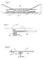
- The second embodiment is illustrated in Figures 3 to 5 and is the same or similar as the first embodiment except as described below.
- In the embodiment of Figures 3 and 4 an edge liquid supply system provides liquid to a
reservoir 30 via aport 40. The liquid in thereservoir 30 is optionally the same as the immersion liquid in the liquid supply system. Thereservoir 30 is positioned on the opposite side of the substrate W to the projection lens and adjacent the edge of the substrate W and the edge of theedge seal member edge seal member 17 is comprised of an element which is separate to the substrate table WT whereas in Figure 3 theedge seal member 117 is provided by an integral portion of the substrate table WT. As can be seen most clearly from Figure 3, the substrate W is supported on the substrate table WT by a so-called pimple table 20. The pimple table 20 comprises a plurality of projections on which the substrate W rests. The substrate W is held in place by, e.g., a vacuum source sucking the substrate onto the top surface of the substrate table WT. With the use of thereservoir 30, when the edge of the substrate W is being imaged, (i.e. when liquid in the liquid supply system under the projection lens traverses across an edge of the substrate), liquid cannot escape from the liquid supply system into the gap between theedge seal member - The
mechanism 170 shown in Figure 4 for moving theedge seal member 17 relative to the remainder of the substrate table WT is illustrated in detail in Figure 5. The reason for moving theedge seal member 17 in this way is so that its primary surface can be made to be substantially co-planar with the primary surface of the substrate W. This allows a smooth movement of the liquid supply system over edge portions of the substrate W so that the bottom inner periphery of the liquid supply system can be moved to positions partly on the primary surface of substrate W and partly on the primary surface of theedge seal member 17. - A level sensor (not illustrated) is used to detect the relative heights of the primary surfaces of the substrate W and the
edge seal member 17. Based on the results of the level sensor, control signals are sent to theactuator 171 in order to adjust the height of the primary surface of theedge seal member 17. A closed loop actuator could also be used for this purpose. - The
actuator 171 is a rotating motor which rotates ashaft 176. Theshaft 176 is connected to a circular disc at the end distal to themotor 171. Theshaft 176 is connected away from the centre of the disc. The disc is located in a circular recess in awedge portion 172. Ball bearings may be used to reduce the amount of friction between the circular disc and the sides of the recess in thewedge portion 172. Themotor 171 is held in place byleaf springs 177. On actuation of the motor the wedge portion is driven to the left and right as illustrated (i.e. in the direction of the slope of the wedge portion) because of the excentre position of theshaft 176 in the disc. The motor is prevented from moving in the same direction as the direction of movement of thewedge portion 172 by thesprings 177. - As the
wedge portion 172 moves left and right as illustrated in Figure 6, its top surface 175 (which is the surface of the wedge which is sloped in relation to the primary surface of the edge seal member 17) contacts the bottom sloped surface of afurther wedge member 173 which is fixed to the bottom of theedge seal member 17. Theedge seal member 17 is prevented from moving in the direction of movement of thewedge member 172 so that when thewedge member 172 moves left and right theedge seal member 17 is lowered and raised respectively. Some biasing of theedge seal member 17 towards the substrate table WT may be necessary. - Obviously the
further wedge member 173 could be replaced by an alternative shape, for example a rod positioned perpendicularly to the direction of movement of thewedge 172. If the coefficient of friction between thewedge member 172 and thefurther wedge member 173 is greater than the tangent of the wedge angle then theactuator 170 is self-braking meaning that no force is required on thewedge member 172 to hold it in place. This is advantageous as the system will then be stable when theactuator 171 is not actuated. The accuracy of themechanism 170 is of the order of a few µm. - Especially in the case of the
edge seal member 117 being an integral part of the substrate table WT, a mechanism may be provided to adjust the height of the substrate W or the member supporting the substrate W so that the primary surfaces of theedge seal member - The third embodiment is illustrated in Figures 6 and 7 and is the same or similar as the first embodiment except as described below.
- This embodiment is described in relation to an
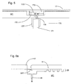
edge seal member 117 which is an integral part of the substrate table WT. However, this embodiment is equally applicable to anedge seal member 17 which is movable relative to the substrate table WT. - In a first version of this embodiment as illustrated in Figure 6a, a further
edge seal member 500 is used to bridge the gap between theedge seal member 117 and the substrate W. The further edge seal member is affixed to theedge seal member 117. The furtheredge seal member 500 is removably attachable against the surface of the substrate W opposite the primary surface. In this embodiment the furtheredge seal member 500 can be a flexible edge seal member which is actuatable to contact the under surface of the substrate W. When the flexibleedge seal member 500 is deactivated it falls away from the substrate under gravity. The way this is achieved is illustrated in Figure 7 and is described below. - It is likely that the further
edge seal member 500 will not prevent all of the immersion liquid from the liquid supply system from entering the space under the substrate W and for this reason aport 46 connected to a low pressure source may be provided under the substrate W adjacent edges of theedge seal member 117 and the substrate W in some or all of the versions of this embodiment. Of course the design of the area under the substrate could be the same as that of the third embodiment. - The same system can be used for sensors such as a transmission image sensor (TIS) on the substrate table as opposed for the substrate W. In the case of sensors, as the sensors do not move, the
edge seal member 500 can be permanently attached to the sensor, for example using glue. - Furthermore, the
edge seal member 500 can be arranged to engage with the top surface of the object (that surface closest to the projection system) rather than the bottom surface. Also, the furtheredge seal member 500 may be provided attached to or near the top surface of theedge seal member 117 as opposed to under theedge seal member 117 as is illustrated in Figure 8a. - A second version of this embodiment is illustrated in Figure 6b. Two further
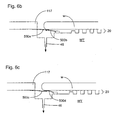
edge seal members edge seal members 500a is the same as in the first version. The second of theseedge seal members 500b is affixed to the substrate table 20 i.e. underneath the substrate W and extends with its free end radially outwardly from its attachment point. The second furtheredge seal member 500b clamps the first furtheredge seal member 500a against the substrate W. Compressed gas can be used to deform or move the second furtheredge seal member 500b. - A third version of this embodiment is shown in Figure 6c. The third version is the same as the second version except the first further
edge seal member 500c clamps the second furtheredge seal member 500d to the substrate W. This avoids, for example, the need for the compressed gas of the second version. - It will be appreciated that the embodiment will also work with only the second further
edge seal member - Various ways of deforming the further
edge seal members - As can be seen from Figure 7, a
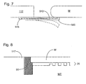
channel 510 is formed in the elongate direction of a flexible further edge seal member 500 (which preferably is an annular ring) and (a) discreet port(s) are provided in an upper surface of the flexible further edge seal member which faces the projection system and the underside of the substrate W. By connecting avacuum source 515 to theduct 510 the flexible further edge seal member can be made to abut the substrate W by suction. When thevacuum source 515 is disconnected or switched off, the flexible furtheredge seal member 500 drops under gravity and/or pressure fromport 46 to assume the position shown in dotted lines in Figure 9. - In an alternative embodiment a flexible further
edge seal member 500 is formed with a mechanical pre-load such that it contacts the substrate W when the substrate is placed on the pimple table 20 and the flexible furtheredge seal member 500 deforms elastically so that it applies a force upwards on the substrate W to thereby make a seal. - In a further alternative, a flexible further
edge seal member 500 may be forced against the substrate W by an overpressure generated by pressurised gas onport 46. - A flexible further
edge seal member 500 may be fashioned from any flexible, radiation and immersion liquid resistant, non-contaminating material, for example, steel, glass e.g. Al2O3, ceramic material e.g. SiC, Silicon, Teflon, low expansion glasses (e.g. Zerodur (TM) or ULE (TM)), carbon fibre epoxy or quartz and is typically between 10 and 500 µm thick, preferably between 30 and 200 µm or 50 to 150 µm in the case of glass. With a flexible furtheredge seal member 500 of this material and these dimensions, the typical pressure which is required to be applied to theduct 510 is approximately 0.1 to 0.6 bar. - The fourth embodiment is illustrated in Figure 8 and is the same or similar as the first embodiment except as described below.
- This embodiment is described in relation to an
edge seal member 117 which is an integral part of the substrate table WT. However, this embodiment is equally applicable to anedge seal member 17 which is movable relative to the substrate table WT. - In the fourth embodiment the gap between the
edge seal member 117 and the substrate W is filled with a furtheredge seal member 50. The further edge seal member is a flexible furtheredge seal member 50 which has a top surface which is substantially co-planar with the primary surfaces of the substrate W and theedge seal member 117. The flexible furtheredge seal member 50 is made of a compliant material so that minor variations in the diameter of substrate W and in the thickness of the substrate W can be accommodated by deflections of the flexible furtheredge seal member 50. When liquid in the liquid supply system under the projection lens passes over the edge of the substrate, the liquid cannot escape between the substrate W, flexible furtheredge seal member 50 andedge seal member 117 because the edges of those elements are tight against one another. Furthermore, because the primary surfaces of the substrate W and theedge seal member 117 and the top surface of the flexible furtheredge seal member 50 are substantially co-planar, the liquid supply system operation is not upset when it passes over the edge of the substrate W so that disturbance forces are not generated in the liquid supply system. - As can be seen from Figure 8, the flexible further
edge seal member 50 is in contact with a surface of the substrate W opposite the primary surface of the substrate W, at an edge portion. This contact has two functions. First the fluid seal between the flexible furtheredge seal member 50 and the substrate W is improved. Second, the flexible furtheredge seal member 50 applies a force on the substrate W in a direction away from the pimple table 20. When the substrate W is held on the substrate table WT by, e.g. vacuum suction, the substrate can be held securely on the substrate table. However, when the vacuum source is switched off or disconnected, the force produced by the flexible furtheredge seal member 50 on the substrate W is effective to push the substrate W off the substrate table WT thereby aiding loading and unloading of substrates W. - The flexible further
edge seal member 50 is made of a radiation and immersion liquid resistant material such as PTFE. - Figure 9 illustrates a fifth embodiment of the present invention which is the same or similar as the first embodiment except as described below.
- This embodiment is described in relation to an
edge seal member 117 which is an integral part of the substrate table WT. However, this embodiment is equally applicable to anedge seal member 17 which is movable relative to the substrate table WT. - As can be seen from Figure 9, the eighth embodiment includes a further
edge seal member 100 for bridging the gap between theedge seal member 117 and the substrate W. In this case the furtheredge seal member 100 is a gap seal member which is positioned on the primary surfaces of the substrate W and theedge seal member 117 to span the gap between the substrate W andedge seal member 117. Thus, if the substrate W is circular, thegap seal member 100 will also be circular (annular). - The
gap seal member 100 may be held in place by the application of avacuum 105 to its underside (that is a vacuum source exposed through a vacuum port on the primary surface of the edge seal member 117). The liquid supply system can pass over the edge of the substrate W without the loss of liquid because the gap between the substrate W and theedge seal member 117 is covered over by the gap seal means 100. Thegap seal member 100 can be put in place and removed by the substrate handler so that standard substrates and substrate handling can be used. Alternatively thegap seal member 100 can be kept at the projection system PL and put in place and removed by appropriate mechanisms (e.g. a substrate handling robot). Thegap seal member 100 should be stiff enough to avoid deformation by the vacuum source. Advantageously thegap seal member 100 is less than 50, preferably 30 or 20 or even 10 µm thick to avoid contact with the liquid supply system, but should be made as thin as possible - The
gap seal member 100 is advantageously provided with taperededges 110 in which the thickness of thegap seal member 100 decreases towards the edges. This gradual transition to the full thickness of the gap seal member ensures that disturbance of the liquid supply system is reduced when it passes on top of thegap seal member 100. - The same way of sealing may be used for other objects such as sensors, for example transmission image sensors. In this case, as the object is not required to move, the gap seal means 100 can be glued in place (at either end) with a glue which does not dissolve in the immersion liquid. The glue can alternatively be positioned at the junction of the
edge seal member 117, the object and the gap seal means 100. - Furthermore, the gap seal means 100 can be positioned underneath the object and an overhang of the
edge seal member 117. The object may be shaped with an overhang also, if necessary. - The gap seal means 100, whether above or below the object, can have a passage provided through it, from one opening in a surface in contact with the edge seal means 117 to another opening in a surface in contact with the object. By positioning one opening in fluid communication with
vacuum 105, the gap seal means 100 can then be kept tightly in place. - The sixth embodiment will be described with reference to Figure 10. The solution shown in Figure 10 bypasses some of the problems associated with imaging edge portions of the substrate W as well as allows a transmission image sensor (TIS) 220 to be illuminated by the projection lens PL under the same conditions as the substrate W.
- The sixth embodiment uses the liquid supply system described with respect to the first embodiment. However, rather than confining the immersion liquid in the liquid supply system under the projection lens on its lower side with the substrate W, the liquid is confined by an
intermediary plate 210 which is positioned between the liquid supply system and the substrate W. Thespaces intermediary plate 210 and theTIS 220 and the substrate W are also filled withliquid 111. This may either be done by two separate space liquid supply systems viarespective ports ports space 215 between the substrate W and theintermediary plate 210 and thespace 220 between thetransmission image sensor 220 and theintermediary plate 210 are both filled with liquid and both the substrate W and the transmission image sensor can be illuminated under the same conditions.Portions 200 provide a support surface or surfaces for theintermediary plate 210 which may be held in place by vacuum sources. - The
intermediary plate 210 is made of such a size that it covers all of the substrate W as well as thetransmission image sensor 220. Therefore, no edges need to be traversed by the liquid supply system even when the edge of the substrate W is imaged or when the transmission image sensor is positioned under the projection lens PL. The top surface of thetransmission image sensor 220 and the substrate W are substantially co-planar. - The
intermediate plate 210 can be removable. It can, for example, be put in place and removed by a substrate handling robot or other appropriate mechanism. - All of the above described embodiments may be used to seal around the edge of the substrate W. Other objects on the substrate table WT may also need to be sealed in a similar way, such as sensors including sensors and/or marks which are illuminated with the projection beam through the liquid such as the transmission image sensors, integrated lens interferometer and scanner (wavefront sensor) and spot sensor plates. Such objects may also include sensors and/or marks which are illuminated with non-projection radiation beams such as levelling and alignment sensors and/or marks. The liquid supply system may supply liquid to cover all of the object in such a case. Any of the above embodiments may be used for this purpose. In some instances, the object will not need to be removed from the substrate table WT as, in contrast to the substrate W, the sensors do not need to be removed from the substrate table WT. In such a case the above embodiments may be modified as appropriate (e.g. the seals may not need to be moveable).
- Each of the embodiments may be combined with one or more of the other embodiments as appropriate. Further, each of the embodiments (and any appropriate combination of embodiments) can be applied simply to the liquid supply system of Figure 2 and Figures 11 and 12 without the
edge seal member - The shape of the
edge seal member 117 and the top outer most edge of thesensor 220 can be varied. For example, it may be advantageous to provide an overhangingedge seal member 117 or indeed an outer edge of thesensor 220 which is overhanging. Alternatively, an outer upper corner of thesensor 220 may be useful. - Figure 11 shows a seventh embodiment which is the same as the first embodiment except as described below.
- In the seventh embodiment the object on the substrate table WT is a
sensor 220 such as a transmission image sensor (TIS). In order to prevent immersion liquid seeping underneath thesensor 220, a bead ofglue 700 which is undissolvable and unreactable with the immersion fluid is positioned between theedge seal member 117 and thesensor 220. The glue is covered by immersion fluid in use. - The eighth embodiment is described with reference to Figures 12 and 13. In the eighth embodiment it is a
sensor 220 which is being sealed to the substrate table WT. In both versions illustrated in Figures 12 and 13, avacuum 46 is provided adjacent the gap with anopening passage 47 and achamber 44 for taking away any immersion liquid which should find its way through the gap between theedge seal member 117 and the edge of thesubstrate 220. - In the Figure 12 version, the
vacuum 46 is provided in the substrate table WT under an overhang portion of theobject 220. Thepassage 47 is provided in an overhanging inwardly protruding portion of the substrate table WT. Optionally a bead ofglue 700 is positioned at the inner most edge of the protruding portion between the substrate table WT and theobject 220. If no bead ofglue 700 is provided, a flow of gas from underneath theobject 220 helps seal the gap between thesensor 220 and the substrate table WT. - In the version of Figure 13, the
vacuum 46,compartment 44 andpassage 47 are provided in theobject 220 itself under an inwardly protrudingedge seal member 117. Again there is the option of providing a bead of glue between theobject 220 and the substrate table WT radially outwardly of thepassage 47. - Substrate-level sensors according to embodiments of the invention comprise a radiation-receiving element (1102, 1118) and a radiation-detecting element (1108, 1124, 1140) as shown in Figure 16. Exposure radiation is directed from the final element of the projection system PL through an
immersion liquid 11 at least partly filling a space between the final element of the projection system PL and the substrate W. The detailed configuration of each of these elements depends on the properties of the radiation to be detected. The sensor at substrate level may comprise a photocell only, for use in cases where it is desirable for the photocell to receive the radiation directly. Alternatively, the sensor at substrate level may comprise a luminescence layer in combination with a photocell. In this arrangement, radiation at a first wavelength is absorbed by the luminescence layer and reradiated a short time later at a second (longer) wavelength. This arrangement is useful, for example, where the photocell is designed to work more efficiently at the second wavelength. - The radiation-receiving element (1112, 1118), which may be a layer with a pinhole, a grating or another diffractive element fulfilling a similar function, may be supported on top of a
quartz sensor body 1120, i.e. on the same side of the body as the projection system. The radiation-detecting element (1108, 1124, 1140), in contrast, may be arranged within thesensor body 1120, or within a concave region formed on the side of thesensor body 1120 facing away from the projection system. - At boundaries between media of different refractive indices a proportion of incident radiation will be reflected and potentially lost from the sensor. For optically smooth surfaces, the extent to which this occurs depends on the angle of incidence of the radiation and the difference in refractive index of the media in question. For radiation incident at and above a "critical angle" (conventionally measured from normal incidence) total internal reflection may occur, leading to serious loss of signal to later elements of the sensor. This may be a particular problem in high NA systems where radiation may have a higher average angle of incidence. The present invention provides arrangements whereby air is excluded from the region between the radiation-receiving (1102, 1118) and radiation-detecting (1108, 1124, 1140) elements in order to avoid interfaces between media of high refractive index and air.
- In addition to losses due to partial and total internal reflection, absorption may also seriously reduce the intensity of radiation intensity reaching the photocell, as may scattering from interfaces that are not optically smooth.
- Figure 16 shows an ILIAS sensor module according to the prior art. This module has a
shearing grating structure 1102 as radiation-receiving element, supported by atransmissive plate 1104, which may be made of glass or quartz. Aquantum conversion layer 1106 is positioned immediately above a camera chip 1108 (the radiation-detecting element), which is in turn mounted on asubstrate 1110. Thesubstrate 1110 is connected to thetransmissive plate 1104 viaspacers 1112 andbonding wires 1114 connect the radiation-detecting element to external instrumentation. An air gap is located between thequantum conversion layer 1106 and thetransmissive plate 1104. In a setup such as this designed for 157 nm radiation, for example, the air gap within the sensor cannot easily be purged so that it will contain significant proportions of oxygen and water, which absorb radiation. Signal is therefore lost and the effect becomes worse for larger angles as these have a longer path length through air. Thus, the dynamic range requirements for the sensor become more severe. - Figures 17 and 18 show improved ILIAS sensor modules according to embodiments of the present invention. In Figure 17, the air gap has been removed by changing the shape of the
transmissive plate 1104 to fit directly to thecamera 1108. This arrangement is made more difficult by the need to provide access for thebonding wires 1114 and necessitates an elongated form. From an engineering point of view, the alternative arrangement shown in Figure 18 is easier to realize. Here, afiller sheet 1116 of the same material as thetransmissive plate 1104, or of similar optical properties, is inserted between thetransmissive plate 1104 and thequantum conversion layer 1106. The removal of the air gap reduces transmission losses and relaxes dynamic range requirements (or, alternatively speaking, improves the effective dynamic range). Both arrangements improve refractive index matching and reduce the extent of spurious internal reflections at the interface with thetransmissive plate 1104. - Figure 19a shows a DUV transmission image sensor according to the prior art. Figure 19b shows a magnified view of the processing element for clarity. The pattern of
transmissive grooves 1118, constituting the radiation-receiving element in this case, is realized by means of e-beam lithography and dry etching techniques in a thin metal layer deposited on a substrate by means of sputtering. Any DUV light that is projected towards thegrooves 1118 is transmitted by the transmissive plate 1104 (which may be quartz or fused silica) and hits the underlyingluminescent material 1122, or "phosphor". Theluminescent material 1122 may consist of a slab of crystalline material that is doped with rare-earth ions, e.g. yttrium-aluminium-garnet doped with cerium (YAG:Ce). The main purpose of theluminescent material 1122 is to convert the DUV radiation into more easily detectable visible radiation, which is then detected by thephotodiode 1124. DUV radiation that has not been absorbed and converted into visible radiation by thephosphor 1122 may be filtered out before it reaches the photodiode 1124 (e.g. by a BG-39 or UG filter 26). - In the above arrangement, air may be present in the gaps between components mounted in the
sensor housing 1125, yielding a number of air/material/air interfaces that interrupt the propagation of radiation. By considering the path of DUV radiation and radiation arising from luminescence, it is possible to identify regions where radiation is likely to be lost. The first region of interest is the rear-side 1128 of thetransmissive plate 1104, reached by DUV radiation after it has passed through thegrooves 1118 andtransmissive plate 1104. Here, the surface has been formed by mechanical means, such as by drilling, and is inevitably rough on the scale of the wavelength of the radiation. Radiation may therefore be lost due to scattering, either back into thetransmissive plate 1104 or out past theluminescent material 1122. Secondly, after this interface, the DUV light encounters the optically smooth air/YAG:Ce interface, where a substantial amount of reflection may occur due to the refractive index mismatch, particularly in systems of high NA. Thirdly, theluminescent material 1122 emits radiation in random directions. Due to its relatively high refractive index, the critical angle for total internal reflection at the YAG:Ce/air boundary is around 33° (there is air in the gap between the YAG:Ce and the filter) from the normal, meaning that a large proportion of radiation incident on the boundary is reflected out of the system and lost through the side walls of theluminescent material 1122. Finally, the part of the luminescence that is directed towards the photodiode has to overcome the air/quartz interface on the diode surface where surface roughness may again account for loss of detected signal. - Whilst specific embodiments of the invention have been described above, it will be appreciated that the invention may be practiced otherwise than as described. In particular, the invention is also applicable to other types of liquid supply systems, especially localised liquid area systems. If the seal member solution is used, it may be one in which a seal other than a gas seal is used. The description is not intended to limit the invention.
Claims (12)
- A lithographic projection apparatus comprising:characterized by at least one sensor being positioned for illumination by said projection beam of radiation which has passed through said immersion liquid.a radiation system for providing a projection beam of radiation;a support structure for supporting patterning means, the patterning means serving to pattern the projection beam according to a desired pattern;a substrate table for holding a substrate;a projection system for projecting the patterned beam onto a target portion of the substrate; anda liquid supply system for at least partly filling the space between the final element of said projection system and an object positioned on the substrate table, with liquid,
- A lithographic projection apparatus according to claim 1, wherein said substrate table comprises a support surface for supporting an intermediary plate between said projection system and the sensor and not in contact with the sensor.
- An apparatus according to claim 2, wherein said substrate table further comprises a transmission image sensor for sensing said beam and wherein said intermediary plate is positionable between said sensor and said projection system.
- A lithographic projection apparatus according to any one of claims 1 to 3, wherein said sensor is positioned on said substrate table.
- A lithographic projection apparatus according to any one of the preceding claims, wherein said sensor is an alignment sensor used for aligning said substrate table relative to said projection system.
- A lithographic projection apparatus according to claim 5, wherein measurement gratings of said alignment sensor have a pitch of less than 500 nm.
- A lithographic projection apparatus according to claim 5 or 6, wherein said alignment sensor is for being illuminated obliquely.
- A lithographic projection apparatus according to claim 1, 2 or 4, wherein said sensor is a transmission image sensor.
- A lithographic projection apparatus according to claim 1, 2 or 4, wherein said sensor is a focus sensor.
- A lithographic projection apparatus according to claim 1, 2 or 4, wherein said sensor is a spot or dose sensor, or an integrated lens interferometer and scanner, or alignment marks.
- A lithographic projection apparatus according to any one of the preceding claims, wherein said substrate table further comprises an edge seal member for at least partly surrounding an edge of the sensor and for providing a primary surface facing said projection system substantially co-planar with a primary surface of said sensor and in that said liquid supply system provides liquid to a localised area of said sensor.
- A device manufacturing method comprising the steps of:characterized by projecting said beam of radiation onto a sensor through said immersion liquid.providing a substrate that is at least partially covered by a layer of radiation-sensitive material;providing a projection beam of radiation using a radiation system;using patterning means to endow the projection beam with a pattern in its cross-section;projecting the patterned beam of radiation onto a target portion of the layer of radiation-sensitive material,providing a liquid to at least partly fill the space between an object on the substrate table and a final element of a projection system used in said step of projecting;
Priority Applications (1)
| Application Number | Priority Date | Filing Date | Title |
|---|---|---|---|
| EP04253354.7A EP1486828B1 (en) | 2003-06-09 | 2004-06-04 | Lithographic apparatus and device manufacturing method |
Applications Claiming Priority (7)
| Application Number | Priority Date | Filing Date | Title |
|---|---|---|---|
| EP03253636 | 2003-06-09 | ||
| EP03253636 | 2003-06-09 | ||
| EP03255395 | 2003-08-29 | ||
| EP03255395 | 2003-08-29 | ||
| EP03257068.1A EP1429188B1 (en) | 2002-11-12 | 2003-11-10 | Lithographic projection apparatus |
| EP03257068 | 2003-11-10 | ||
| EP04253354.7A EP1486828B1 (en) | 2003-06-09 | 2004-06-04 | Lithographic apparatus and device manufacturing method |
Publications (3)
| Publication Number | Publication Date |
|---|---|
| EP1486828A2 true EP1486828A2 (en) | 2004-12-15 |
| EP1486828A3 EP1486828A3 (en) | 2005-08-10 |
| EP1486828B1 EP1486828B1 (en) | 2013-10-09 |
Family
ID=33303965
Family Applications (1)
| Application Number | Title | Priority Date | Filing Date |
|---|---|---|---|
| EP04253354.7A Not-in-force EP1486828B1 (en) | 2003-06-09 | 2004-06-04 | Lithographic apparatus and device manufacturing method |
Country Status (1)
| Country | Link |
|---|---|
| EP (1) | EP1486828B1 (en) |
Cited By (17)
| Publication number | Priority date | Publication date | Assignee | Title |
|---|---|---|---|---|
| WO2005022616A1 (en) | 2003-08-29 | 2005-03-10 | Nikon Corporation | Exposure apparatus and device producing method |
| EP1562079A2 (en) * | 2004-02-09 | 2005-08-10 | Canon Kabushiki Kaisha | Projection exposure apparatus and sensor unit |
| WO2005122219A1 (en) * | 2004-06-09 | 2005-12-22 | Nikon Corporation | Substrate holding device, exposure apparatus having same, exposure method, method for producing device, and liquid repellent plate |
| EP1652003A2 (en) * | 2003-07-08 | 2006-05-03 | Nikon Corporation | Wafer table for immersion lithography |
| EP1696272A3 (en) * | 2005-02-28 | 2006-09-27 | ASML Netherlands BV | A sensor for use in a lithographic apparatus |
| EP1736830A1 (en) * | 2005-06-24 | 2006-12-27 | ASML Netherlands B.V. | Lithographic apparatus and device manufacturing method |
| EP1739489A2 (en) * | 2005-06-29 | 2007-01-03 | ASML Netherlands BV | Lithographic apparatus immersion damage control |
| EP1775636A1 (en) * | 2005-10-11 | 2007-04-18 | ASML Netherlands BV | A lithographic apparatus |
| EP1783555A2 (en) * | 2005-11-08 | 2007-05-09 | ASML Netherlands B.V. | Lithographic apparatus and device manufacturing method |
| NL1030443C2 (en) * | 2005-11-16 | 2007-05-22 | Taiwan Semiconductor Mfg | Immersion fluid is created for immersion lithography system with wafer sealing mechanism for use with predetermined part of wafer edge to prevent fluid leakage |
| EP1788446A2 (en) | 2005-11-16 | 2007-05-23 | Canon Kabushiki Kaisha | Exposure apparatus and device manufacturing method |
| NL1032989C2 (en) * | 2005-12-05 | 2008-06-02 | Taiwan Semiconductor Mfg | Arrangements with a sealing ring for immersion lithography systems. |
| EP1970763A2 (en) | 2004-12-08 | 2008-09-17 | ASML Netherlands BV | Lithographic apparatus and device manufacturing method |
| EP1715380A3 (en) * | 2005-04-20 | 2009-01-21 | Canon Kabushiki Kaisha | Exposure apparatus, method applied to the apparatus, and device manufacturing method |
| US7768625B2 (en) | 2005-06-02 | 2010-08-03 | Canon Kabushiki Kaisha | Photo detector unit and exposure apparatus having the same |
| US8943870B2 (en) | 2008-11-11 | 2015-02-03 | Wila B.V. | Device for clamping a tool |
| JP2018041107A (en) * | 2004-03-25 | 2018-03-15 | 株式会社ニコン | Exposure apparatus and device fabrication method |
Citations (13)
| Publication number | Priority date | Publication date | Assignee | Title |
|---|---|---|---|---|
| US4509852A (en) | 1980-10-06 | 1985-04-09 | Werner Tabarelli | Apparatus for the photolithographic manufacture of integrated circuit elements |
| US5229872A (en) | 1992-01-21 | 1993-07-20 | Hughes Aircraft Company | Exposure device including an electrically aligned electronic mask for micropatterning |
| US5296891A (en) | 1990-05-02 | 1994-03-22 | Fraunhofer-Gesellschaft Zur Forderung Der Angewandten Forschung E.V. | Illumination device |
| US5523193A (en) | 1988-05-31 | 1996-06-04 | Texas Instruments Incorporated | Method and apparatus for patterning and imaging member |
| EP0834773A2 (en) | 1996-10-07 | 1998-04-08 | Nikon Corporation | Focusing and tilting adjustment system for lithography aligner, manufacturing apparatus or inspection apparatus |
| WO1998033096A1 (en) | 1997-01-29 | 1998-07-30 | Micronic Laser Systems Ab | Method and apparatus for the production of a structure by focused laser radiation on a photosensitively coated substrate |
| WO1998038597A2 (en) | 1997-02-28 | 1998-09-03 | Micronic Laser Systems Ab | Data-conversion method for a multibeam laser writer for very complex microlithographic patterns |
| WO1998040791A1 (en) | 1997-03-10 | 1998-09-17 | Koninklijke Philips Electronics N.V. | Positioning device having two object holders |
| WO1999049504A1 (en) | 1998-03-26 | 1999-09-30 | Nikon Corporation | Projection exposure method and system |
| US5969441A (en) | 1996-12-24 | 1999-10-19 | Asm Lithography Bv | Two-dimensionally balanced positioning device with two object holders, and lithographic device provided with such a positioning device |
| US6046792A (en) | 1996-03-06 | 2000-04-04 | U.S. Philips Corporation | Differential interferometer system and lithographic step-and-scan apparatus provided with such a system |
| EP1571701A1 (en) | 2002-12-10 | 2005-09-07 | Nikon Corporation | Exposure apparatus and method for manufacturing device |
| EP1628330A1 (en) | 2003-05-28 | 2006-02-22 | Nikon Corporation | Exposure method, exposure device, and device manufacturing method |
Family Cites Families (1)
| Publication number | Priority date | Publication date | Assignee | Title |
|---|---|---|---|---|
| JPH11176727A (en) * | 1997-12-11 | 1999-07-02 | Nikon Corp | Projection aligner |
-
2004
- 2004-06-04 EP EP04253354.7A patent/EP1486828B1/en not_active Not-in-force
Patent Citations (13)
| Publication number | Priority date | Publication date | Assignee | Title |
|---|---|---|---|---|
| US4509852A (en) | 1980-10-06 | 1985-04-09 | Werner Tabarelli | Apparatus for the photolithographic manufacture of integrated circuit elements |
| US5523193A (en) | 1988-05-31 | 1996-06-04 | Texas Instruments Incorporated | Method and apparatus for patterning and imaging member |
| US5296891A (en) | 1990-05-02 | 1994-03-22 | Fraunhofer-Gesellschaft Zur Forderung Der Angewandten Forschung E.V. | Illumination device |
| US5229872A (en) | 1992-01-21 | 1993-07-20 | Hughes Aircraft Company | Exposure device including an electrically aligned electronic mask for micropatterning |
| US6046792A (en) | 1996-03-06 | 2000-04-04 | U.S. Philips Corporation | Differential interferometer system and lithographic step-and-scan apparatus provided with such a system |
| EP0834773A2 (en) | 1996-10-07 | 1998-04-08 | Nikon Corporation | Focusing and tilting adjustment system for lithography aligner, manufacturing apparatus or inspection apparatus |
| US5969441A (en) | 1996-12-24 | 1999-10-19 | Asm Lithography Bv | Two-dimensionally balanced positioning device with two object holders, and lithographic device provided with such a positioning device |
| WO1998033096A1 (en) | 1997-01-29 | 1998-07-30 | Micronic Laser Systems Ab | Method and apparatus for the production of a structure by focused laser radiation on a photosensitively coated substrate |
| WO1998038597A2 (en) | 1997-02-28 | 1998-09-03 | Micronic Laser Systems Ab | Data-conversion method for a multibeam laser writer for very complex microlithographic patterns |
| WO1998040791A1 (en) | 1997-03-10 | 1998-09-17 | Koninklijke Philips Electronics N.V. | Positioning device having two object holders |
| WO1999049504A1 (en) | 1998-03-26 | 1999-09-30 | Nikon Corporation | Projection exposure method and system |
| EP1571701A1 (en) | 2002-12-10 | 2005-09-07 | Nikon Corporation | Exposure apparatus and method for manufacturing device |
| EP1628330A1 (en) | 2003-05-28 | 2006-02-22 | Nikon Corporation | Exposure method, exposure device, and device manufacturing method |
Non-Patent Citations (1)
| Title |
|---|
| PETER VAN ZANT: "Microchip Fabrication: A Practical Guide to Semiconductor Processing", 1997, MCGRAW HILL PUBLISHING CO. |
Cited By (41)
| Publication number | Priority date | Publication date | Assignee | Title |
|---|---|---|---|---|
| EP1652003A2 (en) * | 2003-07-08 | 2006-05-03 | Nikon Corporation | Wafer table for immersion lithography |
| EP1652003A4 (en) * | 2003-07-08 | 2007-10-10 | Nikon Corp | Wafer table for immersion lithography |
| US8508718B2 (en) | 2003-07-08 | 2013-08-13 | Nikon Corporation | Wafer table having sensor for immersion lithography |
| EP2804048A1 (en) * | 2003-08-29 | 2014-11-19 | Nikon Corporation | Exposure apparatus and device fabricating method |
| EP1670039A1 (en) * | 2003-08-29 | 2006-06-14 | Nikon Corporation | Exposure apparatus and device producing method |
| WO2005022616A1 (en) | 2003-08-29 | 2005-03-10 | Nikon Corporation | Exposure apparatus and device producing method |
| EP1670039B1 (en) * | 2003-08-29 | 2014-06-04 | Nikon Corporation | Exposure apparatus and device producing method |
| US9223224B2 (en) | 2003-08-29 | 2015-12-29 | Nikon Corporation | Exposure apparatus with component from which liquid is protected and/or removed and device fabricating method |
| EP1562079A3 (en) * | 2004-02-09 | 2006-10-04 | Canon Kabushiki Kaisha | Projection exposure apparatus and sensor unit |
| US7522264B2 (en) | 2004-02-09 | 2009-04-21 | Canon Kabushiki Kaisha | Projection exposure apparatus, device manufacturing method, and sensor unit |
| EP1562079A2 (en) * | 2004-02-09 | 2005-08-10 | Canon Kabushiki Kaisha | Projection exposure apparatus and sensor unit |
| US7256868B2 (en) | 2004-02-09 | 2007-08-14 | Canon Kabushiki Kaisha | Projection exposure apparatus, device manufacturing method, and sensor unit |
| JP2018041107A (en) * | 2004-03-25 | 2018-03-15 | 株式会社ニコン | Exposure apparatus and device fabrication method |
| WO2005122219A1 (en) * | 2004-06-09 | 2005-12-22 | Nikon Corporation | Substrate holding device, exposure apparatus having same, exposure method, method for producing device, and liquid repellent plate |
| US8705008B2 (en) | 2004-06-09 | 2014-04-22 | Nikon Corporation | Substrate holding unit, exposure apparatus having same, exposure method, method for producing device, and liquid repellant plate |
| EP1970763A3 (en) * | 2004-12-08 | 2013-10-09 | ASML Netherlands BV | Lithographic apparatus and device manufacturing method |
| US8860926B2 (en) | 2004-12-08 | 2014-10-14 | Asml Netherlands B.V. | Lithographic apparatus and device manufacturing method |
| EP1970763A2 (en) | 2004-12-08 | 2008-09-17 | ASML Netherlands BV | Lithographic apparatus and device manufacturing method |
| US8629418B2 (en) | 2005-02-28 | 2014-01-14 | Asml Netherlands B.V. | Lithographic apparatus and sensor therefor |
| US7282701B2 (en) | 2005-02-28 | 2007-10-16 | Asml Netherlands B.V. | Sensor for use in a lithographic apparatus |
| EP1696272A3 (en) * | 2005-02-28 | 2006-09-27 | ASML Netherlands BV | A sensor for use in a lithographic apparatus |
| EP1715380A3 (en) * | 2005-04-20 | 2009-01-21 | Canon Kabushiki Kaisha | Exposure apparatus, method applied to the apparatus, and device manufacturing method |
| US7768625B2 (en) | 2005-06-02 | 2010-08-03 | Canon Kabushiki Kaisha | Photo detector unit and exposure apparatus having the same |
| CN1885169B (en) * | 2005-06-24 | 2010-07-07 | Asml荷兰有限公司 | Lithographic apparatus and device manufacturing method |
| US7372549B2 (en) | 2005-06-24 | 2008-05-13 | Asml Netherlands B.V. | Lithographic apparatus and device manufacturing method |
| EP1736830A1 (en) * | 2005-06-24 | 2006-12-27 | ASML Netherlands B.V. | Lithographic apparatus and device manufacturing method |
| EP1739489A2 (en) * | 2005-06-29 | 2007-01-03 | ASML Netherlands BV | Lithographic apparatus immersion damage control |
| EP1962140A3 (en) * | 2005-06-29 | 2010-07-28 | ASML Netherlands BV | Lithographic apparatus immersion damage control |
| CN1892435B (en) * | 2005-06-29 | 2010-06-09 | Asml荷兰有限公司 | Lithographic apparatus immersion damage control |
| EP1739489A3 (en) * | 2005-06-29 | 2007-06-06 | ASML Netherlands BV | Lithographic apparatus immersion damage control |
| US7755742B2 (en) | 2005-10-11 | 2010-07-13 | Asml Netherlands B.V. | Lithographic apparatus with mounted sensor |
| EP1775636A1 (en) * | 2005-10-11 | 2007-04-18 | ASML Netherlands BV | A lithographic apparatus |
| US7564536B2 (en) | 2005-11-08 | 2009-07-21 | Asml Netherlands B.V. | Lithographic apparatus and device manufacturing method |
| EP1783555A3 (en) * | 2005-11-08 | 2007-05-30 | ASML Netherlands B.V. | Lithographic apparatus and device manufacturing method |
| EP1783555A2 (en) * | 2005-11-08 | 2007-05-09 | ASML Netherlands B.V. | Lithographic apparatus and device manufacturing method |
| US7916273B2 (en) | 2005-11-16 | 2011-03-29 | Canon Kabushiki Kaisha | Exposure apparatus and device manufacturing method |
| EP1788446A3 (en) * | 2005-11-16 | 2007-11-28 | Canon Kabushiki Kaisha | Exposure apparatus and device manufacturing method |
| EP1788446A2 (en) | 2005-11-16 | 2007-05-23 | Canon Kabushiki Kaisha | Exposure apparatus and device manufacturing method |
| NL1030443C2 (en) * | 2005-11-16 | 2007-05-22 | Taiwan Semiconductor Mfg | Immersion fluid is created for immersion lithography system with wafer sealing mechanism for use with predetermined part of wafer edge to prevent fluid leakage |
| NL1032989C2 (en) * | 2005-12-05 | 2008-06-02 | Taiwan Semiconductor Mfg | Arrangements with a sealing ring for immersion lithography systems. |
| US8943870B2 (en) | 2008-11-11 | 2015-02-03 | Wila B.V. | Device for clamping a tool |
Also Published As
| Publication number | Publication date |
|---|---|
| EP1486828B1 (en) | 2013-10-09 |
| EP1486828A3 (en) | 2005-08-10 |
Similar Documents
| Publication | Publication Date | Title |
|---|---|---|
| US10678139B2 (en) | Lithographic apparatus and device manufacturing method | |
| US9740107B2 (en) | Lithographic apparatus and device manufacturing method | |
| EP1429188B1 (en) | Lithographic projection apparatus | |
| US7795603B2 (en) | Lithographic apparatus and device manufacturing method | |
| EP1486828B1 (en) | Lithographic apparatus and device manufacturing method |
Legal Events
| Date | Code | Title | Description |
|---|---|---|---|
| PUAI | Public reference made under article 153(3) epc to a published international application that has entered the european phase |
Free format text: ORIGINAL CODE: 0009012 |
|
| AK | Designated contracting states |
Kind code of ref document: A2 Designated state(s): AT BE BG CH CY CZ DE DK EE ES FI FR GB GR HU IE IT LI LU MC NL PL PT RO SE SI SK TR |
|
| AX | Request for extension of the european patent |
Extension state: AL HR LT LV MK |
|
| PUAL | Search report despatched |
Free format text: ORIGINAL CODE: 0009013 |
|
| AK | Designated contracting states |
Kind code of ref document: A3 Designated state(s): AT BE BG CH CY CZ DE DK EE ES FI FR GB GR HU IE IT LI LU MC NL PL PT RO SE SI SK TR |
|
| AX | Request for extension of the european patent |
Extension state: AL HR LT LV MK |
|
| 17P | Request for examination filed |
Effective date: 20050922 |
|
| AKX | Designation fees paid |
Designated state(s): DE FR GB IT NL |
|
| 17Q | First examination report despatched |
Effective date: 20120103 |
|
| GRAP | Despatch of communication of intention to grant a patent |
Free format text: ORIGINAL CODE: EPIDOSNIGR1 |
|
| GRAS | Grant fee paid |
Free format text: ORIGINAL CODE: EPIDOSNIGR3 |
|
| GRAA | (expected) grant |
Free format text: ORIGINAL CODE: 0009210 |
|
| AK | Designated contracting states |
Kind code of ref document: B1 Designated state(s): DE FR GB IT NL |
|
| REG | Reference to a national code |
Ref country code: GB Ref legal event code: FG4D |
|
| REG | Reference to a national code |
Ref country code: DE Ref legal event code: R096 Ref document number: 602004043516 Country of ref document: DE Effective date: 20131205 |
|
| REG | Reference to a national code |
Ref country code: NL Ref legal event code: VDEP Effective date: 20131009 |
|
| PG25 | Lapsed in a contracting state [announced via postgrant information from national office to epo] |
Ref country code: NL Free format text: LAPSE BECAUSE OF FAILURE TO SUBMIT A TRANSLATION OF THE DESCRIPTION OR TO PAY THE FEE WITHIN THE PRESCRIBED TIME-LIMIT Effective date: 20131009 |
|
| REG | Reference to a national code |
Ref country code: DE Ref legal event code: R097 Ref document number: 602004043516 Country of ref document: DE |
|
| PLBE | No opposition filed within time limit |
Free format text: ORIGINAL CODE: 0009261 |
|
| STAA | Information on the status of an ep patent application or granted ep patent |
Free format text: STATUS: NO OPPOSITION FILED WITHIN TIME LIMIT |
|
| PG25 | Lapsed in a contracting state [announced via postgrant information from national office to epo] |
Ref country code: IT Free format text: LAPSE BECAUSE OF FAILURE TO SUBMIT A TRANSLATION OF THE DESCRIPTION OR TO PAY THE FEE WITHIN THE PRESCRIBED TIME-LIMIT Effective date: 20131009 |
|
| 26N | No opposition filed |
Effective date: 20140710 |
|
| REG | Reference to a national code |
Ref country code: DE Ref legal event code: R097 Ref document number: 602004043516 Country of ref document: DE Effective date: 20140710 |
|
| GBPC | Gb: european patent ceased through non-payment of renewal fee |
Effective date: 20140604 |
|
| PG25 | Lapsed in a contracting state [announced via postgrant information from national office to epo] |
Ref country code: GB Free format text: LAPSE BECAUSE OF NON-PAYMENT OF DUE FEES Effective date: 20140604 |
|
| REG | Reference to a national code |
Ref country code: FR Ref legal event code: PLFP Year of fee payment: 13 |
|
| REG | Reference to a national code |
Ref country code: FR Ref legal event code: PLFP Year of fee payment: 14 |
|
| REG | Reference to a national code |
Ref country code: FR Ref legal event code: PLFP Year of fee payment: 15 |
|
| PGFP | Annual fee paid to national office [announced via postgrant information from national office to epo] |
Ref country code: DE Payment date: 20180625 Year of fee payment: 15 |
|
| PGFP | Annual fee paid to national office [announced via postgrant information from national office to epo] |
Ref country code: FR Payment date: 20180620 Year of fee payment: 15 |
|
| REG | Reference to a national code |
Ref country code: DE Ref legal event code: R119 Ref document number: 602004043516 Country of ref document: DE |
|
| PG25 | Lapsed in a contracting state [announced via postgrant information from national office to epo] |
Ref country code: DE Free format text: LAPSE BECAUSE OF NON-PAYMENT OF DUE FEES Effective date: 20200101 |
|
| PG25 | Lapsed in a contracting state [announced via postgrant information from national office to epo] |
Ref country code: FR Free format text: LAPSE BECAUSE OF NON-PAYMENT OF DUE FEES Effective date: 20190630 |