EP1486718A1 - Pneumatic pipe plug for pipelines, especially gas pipelines - Google Patents
Pneumatic pipe plug for pipelines, especially gas pipelines Download PDFInfo
- Publication number
- EP1486718A1 EP1486718A1 EP04468009A EP04468009A EP1486718A1 EP 1486718 A1 EP1486718 A1 EP 1486718A1 EP 04468009 A EP04468009 A EP 04468009A EP 04468009 A EP04468009 A EP 04468009A EP 1486718 A1 EP1486718 A1 EP 1486718A1
- Authority
- EP
- European Patent Office
- Prior art keywords
- plug
- wall
- cord
- pneumatic
- pipelines
- Prior art date
- Legal status (The legal status is an assumption and is not a legal conclusion. Google has not performed a legal analysis and makes no representation as to the accuracy of the status listed.)
- Withdrawn
Links
Images
Classifications
-
- F—MECHANICAL ENGINEERING; LIGHTING; HEATING; WEAPONS; BLASTING
- F16—ENGINEERING ELEMENTS AND UNITS; GENERAL MEASURES FOR PRODUCING AND MAINTAINING EFFECTIVE FUNCTIONING OF MACHINES OR INSTALLATIONS; THERMAL INSULATION IN GENERAL
- F16L—PIPES; JOINTS OR FITTINGS FOR PIPES; SUPPORTS FOR PIPES, CABLES OR PROTECTIVE TUBING; MEANS FOR THERMAL INSULATION IN GENERAL
- F16L55/00—Devices or appurtenances for use in, or in connection with, pipes or pipe systems
- F16L55/10—Means for stopping flow from or in pipes or hoses
- F16L55/12—Means for stopping flow from or in pipes or hoses by introducing into the pipe a member expandable in situ
- F16L55/128—Means for stopping flow from or in pipes or hoses by introducing into the pipe a member expandable in situ introduced axially into the pipe or hose
- F16L55/132—Means for stopping flow from or in pipes or hoses by introducing into the pipe a member expandable in situ introduced axially into the pipe or hose the closure device being a plug fixed by radially deforming the packing
- F16L55/134—Means for stopping flow from or in pipes or hoses by introducing into the pipe a member expandable in situ introduced axially into the pipe or hose the closure device being a plug fixed by radially deforming the packing by means of an inflatable packing
Definitions
- the subject of the invention is a pneumatic pipe plug for pipelines, preferably gas pipelines, which is used for the working sealing of pipelines, especially gas pipelines during repair or leak testing, whereat it is inserted into the pipeline through a connection in the wall of the pipeline and can be used for the sealing of pipelines of a variety of nominal diameters.
- the technical problem to be solved by the present invention is how to conceive such a pneumatic pipe plug that will be applicable to the sealing of pipelines of various nominal diameters despite the fact that it can be inserted through connections of relatively small diameters located in the wall of the pipeline and is foreseen for high working pressures and dynamic pressures in order to ascertain good sealing, whereat the plug should also be resistant to mechanical damages that could occur when inserting the plug into or removing it from a connection in the wall, said connection being often sharp-edged.
- a plug of this type is known to be produced by the company Kleiss & co bv and it consists of a tube-like cylindrical part made of latex reinforced by fibres running parallel or obliquely to the longitudinal axis of the cylindrical part.
- the fibres are bound with latex by means of a special binder.
- Either end of the cylindrical part is provided with a connecting element for working gas supply and a closing element, said elements being preferably of metal.
- a disadvantage thereof is a multi-stage manufacturing process: the manufacture of the cylindrical element, the placement of fibres, the fastening of fibres, the fitting of the connecting and closing elements, which increases the price of the product.
- a further disadvantage is the sensitivity to mechanical damages.
- the described construction only allows low working and dynamic pressures, which limits its range of use.
- a pipe plug of the invention whose essential characteristic is that it is manufactured of a tube element having the form of an ellipsoid of revolution and made of rubber and reinforced by rubber cord, whereat the wall of the element becomes thinner in the direction from either end towards the centre so that the thicker wall sections are capable of accepting a higher working pressure because these two sections are free, whereas the central thinner wall section is intended for extending and tightly fitting to the wall of the pipeline, which simultaneously acts as an additional support to the thinner central section of the plug wall at accepting a higher working or dynamic pressure in the plug.
- the plug of the invention can cover a larger range of a variety of pipeline diameters at higher working and consequently dynamic pressures.
- the cord integrated in the wall additionally contributes to a higher load-carrying capacity of the product.
- the cord is preferably made of two layers with the fibres of either layer running obliquely with respect to the longitudinal axis of the plug and in different directions.
- a screw spring in a tube running between both ends of the plug and giving additional stiffness to the plug in uninflated mode, which is needed when the uninflated plug is pushed into the pipeline through a lateral connection in the pipeline wall.
- a pneumatic pipe plug for pipelines preferably gas pipes consists of an elastic tube element 1 shaped as an ellipsoid of revolution, which is at least at one end closed by a closing element 2 having an opening 3, in which a connecting element 4 is positioned, said element serving as a connection with the pipeline for the supply of compressed gas, preferably air for the inflation of the plug.
- a closing element 2 At an opposite closing element 2 there is an approximately hemispherical end element 5, which acts as the front part of the plug thus simplifying the guiding of the plug through the connection in the wall of the pipeline into the pipeline.
- both closing elements 2 on the first plug are provided with connecting elements 4.
- Both closing elements 2 are simultaneously mutually connected by an elastic element 7, preferably a screw spring, which facilitates the guiding of the uninflated plug through the wall connection on the pipeline.
- an elastic element 7 preferably a screw spring
- the element 7 within a tube 6 offers enough stiffness for the plug to be pushed without bending, whereas during inflation in the pipeline the element 7 within the tube 6 can bend and allow the shrinking of the plug in axial direction due to its extension in transversal direction.
- the tube 6 and the elastic element 7 lie preferably coaxially.
- a wall 8 of the element 1 is such that its thickness diminishes towards the centre and can contain a gummed cord 9.
- This cord 9 can run in several layers, preferably in two layers so that, with respect to the longitudinal axis of the element 1, one cord 9 lies obliquely to one side and another cord to the other side for an angle ⁇ , measured from the central line and amounting to 0 - 20°.
- the wall 8 is manufactured from rubber containing at least one layer of the gummed cord 9 according to the vulcanization method, during which also the closing elements 2 are placed into the element 1.
- the plugs may be manufactured in several dimensions so that they cover a very wide range of diameters of pipelines or gas lines they are intended for.
Abstract
Description
- The subject of the invention is a pneumatic pipe plug for pipelines, preferably gas pipelines, which is used for the working sealing of pipelines, especially gas pipelines during repair or leak testing, whereat it is inserted into the pipeline through a connection in the wall of the pipeline and can be used for the sealing of pipelines of a variety of nominal diameters.
- The technical problem to be solved by the present invention is how to conceive such a pneumatic pipe plug that will be applicable to the sealing of pipelines of various nominal diameters despite the fact that it can be inserted through connections of relatively small diameters located in the wall of the pipeline and is foreseen for high working pressures and dynamic pressures in order to ascertain good sealing, whereat the plug should also be resistant to mechanical damages that could occur when inserting the plug into or removing it from a connection in the wall, said connection being often sharp-edged.
- A plug of this type is known to be produced by the company Kleiss & co bv and it consists of a tube-like cylindrical part made of latex reinforced by fibres running parallel or obliquely to the longitudinal axis of the cylindrical part. The fibres are bound with latex by means of a special binder. Either end of the cylindrical part is provided with a connecting element for working gas supply and a closing element, said elements being preferably of metal.
- A disadvantage thereof is a multi-stage manufacturing process: the manufacture of the cylindrical element, the placement of fibres, the fastening of fibres, the fitting of the connecting and closing elements, which increases the price of the product. A further disadvantage is the sensitivity to mechanical damages. The described construction only allows low working and dynamic pressures, which limits its range of use.
- Another known plug is that of the company Staedtler + beck GmbH, which has a rubber basis in the shape of a ball and covered by textile. Since it is not reinforced, it is only suitable for lower working and dynamic pressures. Consequently, the sealing of pipelines is poorer.
- The described technical problem is solved by a pipe plug of the invention, whose essential characteristic is that it is manufactured of a tube element having the form of an ellipsoid of revolution and made of rubber and reinforced by rubber cord, whereat the wall of the element becomes thinner in the direction from either end towards the centre so that the thicker wall sections are capable of accepting a higher working pressure because these two sections are free, whereas the central thinner wall section is intended for extending and tightly fitting to the wall of the pipeline, which simultaneously acts as an additional support to the thinner central section of the plug wall at accepting a higher working or dynamic pressure in the plug. The plug of the invention can cover a larger range of a variety of pipeline diameters at higher working and consequently dynamic pressures.
- The cord integrated in the wall additionally contributes to a higher load-carrying capacity of the product. The cord is preferably made of two layers with the fibres of either layer running obliquely with respect to the longitudinal axis of the plug and in different directions.
- Within the plug there is a screw spring in a tube running between both ends of the plug and giving additional stiffness to the plug in uninflated mode, which is needed when the uninflated plug is pushed into the pipeline through a lateral connection in the pipeline wall.
- The essence of the invention will now be described in more detail by way of an embodiment and with reference to the accompanying drawings in which:
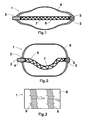
- Fig. 1 shows a longitudinal cross-section of the plug of the invention in uninflated state,
- Fig. 2 shows the same in inflated state,
- Fig. 3 is a schematic view of the position of the cord in the wall of the inventive plug before vulcanization.
-
- A pneumatic pipe plug for pipelines, preferably gas pipes consists of an
elastic tube element 1 shaped as an ellipsoid of revolution, which is at least at one end closed by aclosing element 2 having anopening 3, in which a connecting element 4 is positioned, said element serving as a connection with the pipeline for the supply of compressed gas, preferably air for the inflation of the plug. At anopposite closing element 2 there is an approximatelyhemispherical end element 5, which acts as the front part of the plug thus simplifying the guiding of the plug through the connection in the wall of the pipeline into the pipeline. - Should the sealing or closing of a section of the pipeline between at least two points be needed, at least two plugs are connected in a row so that the second plug is inflatable together with the first plug. In this case both
closing elements 2 on the first plug are provided with connecting elements 4. - Both
closing elements 2 are simultaneously mutually connected by anelastic element 7, preferably a screw spring, which facilitates the guiding of the uninflated plug through the wall connection on the pipeline. When shifted through the connection in the wall of the pipeline, theelement 7 within atube 6 offers enough stiffness for the plug to be pushed without bending, whereas during inflation in the pipeline theelement 7 within thetube 6 can bend and allow the shrinking of the plug in axial direction due to its extension in transversal direction. - If the plug is intended for a consecutive connection of a pressure medium, the
tube 6 and theelastic element 7 lie preferably coaxially. - A
wall 8 of theelement 1 is such that its thickness diminishes towards the centre and can contain agummed cord 9. Thiscord 9 can run in several layers, preferably in two layers so that, with respect to the longitudinal axis of theelement 1, onecord 9 lies obliquely to one side and another cord to the other side for an angle α, measured from the central line and amounting to 0 - 20°. - The
wall 8 is manufactured from rubber containing at least one layer of thegummed cord 9 according to the vulcanization method, during which also theclosing elements 2 are placed into theelement 1. - To suit the requirements, the plugs may be manufactured in several dimensions so that they cover a very wide range of diameters of pipelines or gas lines they are intended for.
Claims (6)
- A pneumatic pipe plug for pipelines, preferably gas pipes consisting of an elastic tube element (1) closed at both ends by closing elements (2), preferably made of rubber and metal, whereat in at least one element (2) there is an opening (3), in which a connecting element (4) is positioned, said element serving as a connection with a pipeline for the supply of compressed gas, preferably air for the inflation of the plug, and at the opposite closing element (2) there is an approximately hemispherical end element (5) acting as the front part of the plug thus simplifying the guiding of the plug through the connection in the wall of the pipeline, and in the element (1) between the closing elements (2) there is a tube (6) containing an elastic element (7), preferably a screw spring, characterized in that the tube element (1) is in the form of an ellipsoid of revolution.
- A pneumatic pipe plug according to claim 1, characterized in that the thickness of a wall (8) of the element (1) becomes thinner towards the centre.
- A pneumatic pneumatic plug according to claims 1 and 2, characterized in that the wall (8) of the element (1) can contain a gummed cord (9).
- A pneumatic pipe plug according to claims 1 to 3, characterized in that the cord (9) in the wall (8) can run in several layers, preferably in two layers so that, with respect to the longitudinal axis of the element (1), one cord (9) lies obliquely to one side and another cord (9) to the other side for an angle α measured from the central line and amounting to 0 - 20°.
- A pneumatic pipe plug according to claims 1 to 3, characterized in that both closing elements (2) can be equipped with connecting elements (4), whereat inside the plug there is a connection for a pressure medium via an elastic tube (6) between two connecting elements (4).
- A pneumatic end plug according to claims 1 to 5, characterized in that the wall (8) of the element (1) is manufactured according to vulcanization process.
Applications Claiming Priority (2)
| Application Number | Priority Date | Filing Date | Title |
|---|---|---|---|
| SI200300142 | 2003-06-11 | ||
| SI200300142A SI21516A (en) | 2003-06-11 | 2003-06-11 | Pneumatic locking cap for pipelines, particularly gas pipelines |
Publications (1)
| Publication Number | Publication Date |
|---|---|
| EP1486718A1 true EP1486718A1 (en) | 2004-12-15 |
Family
ID=33297632
Family Applications (1)
| Application Number | Title | Priority Date | Filing Date |
|---|---|---|---|
| EP04468009A Withdrawn EP1486718A1 (en) | 2003-06-11 | 2004-06-02 | Pneumatic pipe plug for pipelines, especially gas pipelines |
Country Status (3)
| Country | Link |
|---|---|
| US (1) | US20040250867A1 (en) |
| EP (1) | EP1486718A1 (en) |
| SI (1) | SI21516A (en) |
Cited By (4)
| Publication number | Priority date | Publication date | Assignee | Title |
|---|---|---|---|---|
| WO2006049509A3 (en) * | 2004-11-01 | 2007-09-07 | Richard Ord | Inflatable blocking assembly for pipes, ducts, shafts, drains and the like |
| ITBO20130348A1 (en) * | 2013-07-04 | 2015-01-05 | I S I F S R L | DEVICE FOR FACILITATING INSERTION OF A HOLDING BALLOON IN A CONDUCTURE |
| CN106958713A (en) * | 2017-04-21 | 2017-07-18 | 佛山腾谱工业设计有限公司 | A kind of municipal underground piping cut-off constructing device |
| CN107166130A (en) * | 2017-07-12 | 2017-09-15 | 李二霞 | Novel water conservancy project ductile iron pipe plug component |
Families Citing this family (4)
| Publication number | Priority date | Publication date | Assignee | Title |
|---|---|---|---|---|
| US9417153B2 (en) * | 2012-09-27 | 2016-08-16 | Redline Detection, Llc | Balloon catheter apparatus for high pressure leak detection |
| US10689939B1 (en) | 2017-02-22 | 2020-06-23 | Mitchell L. White | Downhole plug |
| CN110185878B (en) * | 2019-05-05 | 2021-07-20 | 泉州市燃气有限公司 | Plugging device for rush repair of natural gas pipeline |
| RU2771407C1 (en) * | 2021-06-21 | 2022-05-04 | Михаил Иосифович Трибельский | Device for sealing pipelines |
Citations (9)
| Publication number | Priority date | Publication date | Assignee | Title |
|---|---|---|---|---|
| GB2107423A (en) * | 1981-10-19 | 1983-04-27 | Alh Syst Ltd | Sealing pipes |
| US5503188A (en) * | 1993-12-30 | 1996-04-02 | Petrone; Joseph A. | Inflatable air bag pipeline stopper |
| US5771937A (en) * | 1996-12-13 | 1998-06-30 | Mcp Industries, Inc. | Pipe plug and method |
| US5901752A (en) * | 1998-06-05 | 1999-05-11 | Lundman; Philip L. | Inflatable apparatus for sealing a pipeline |
| DE29819823U1 (en) * | 1998-11-06 | 2000-03-09 | Diehl Remscheid Gmbh & Co | Expandable cushion for sealing pipes |
| WO2001011283A2 (en) * | 1999-08-06 | 2001-02-15 | A/S Koe-Entreprise | A method of closing a pipe |
| WO2001016518A1 (en) * | 1999-09-01 | 2001-03-08 | Sarco Stopper Limited | Inflatable stopper |
| WO2001075350A1 (en) * | 2000-04-04 | 2001-10-11 | Flexfab Horizons International, Inc. | Repair bladder with heat sink cuff |
| DE20214556U1 (en) * | 2002-09-20 | 2003-01-02 | Staedtler Und Beck Gmbh | Device for stopping a supply pipe, especially gas pipes comprises mounting which is incorporated in the cylindrical body and a steel rod which is fixed to the mounting |
Family Cites Families (14)
| Publication number | Priority date | Publication date | Assignee | Title |
|---|---|---|---|---|
| US3086540A (en) * | 1962-04-19 | 1963-04-23 | Benard C Anderson | Water pressure bulb unit for unclogging drains |
| US4079755A (en) * | 1976-05-04 | 1978-03-21 | Lans Gerald J V D | Inflatable pipe plug |
| CA1117865A (en) * | 1979-11-15 | 1982-02-09 | Fred S. Ditto | Flow plug |
| US4350183A (en) * | 1980-05-19 | 1982-09-21 | Raychem Corporation | Heat-recoverable pipeline termination plug |
| FR2506893B1 (en) * | 1981-05-27 | 1986-01-03 | Caoutchouc Manuf Plastique | TEMPORARY SHUTTERING DEVICE FOR PIPES OR DRILLING HOLES |
| FR2517017B1 (en) * | 1981-11-20 | 1986-09-19 | Caoutchouc Manuf Plastique | |
| US4449584A (en) * | 1982-08-12 | 1984-05-22 | Byron Christensen | Inflatable flowing hole plug |
| US4614206A (en) * | 1985-11-14 | 1986-09-30 | Cherne Industries, Inc. | Expansible pneumatic plug device |
| DE3715645A1 (en) * | 1987-05-11 | 1988-11-24 | Manfred Vetter | PIPE SEALING PILLOW |
| US5379802A (en) * | 1991-03-06 | 1995-01-10 | Vanderlans; Gerald J. | Pipeline stopper plug |
| NL9101900A (en) * | 1991-11-14 | 1993-06-01 | Beugen J Van Beheer Bv | METHOD FOR MANUFACTURING AN INFLATABLE CONNECTION PLUG FOR PIPES |
| DE29906626U1 (en) * | 1999-04-14 | 1999-07-15 | Festo Ag & Co | Actuator |
| US6446669B1 (en) * | 2001-01-04 | 2002-09-10 | Philip L. Lundman | Pipe sealing apparatus |
| US6481465B1 (en) * | 2001-01-23 | 2002-11-19 | Gerard G. Warmerdam | Compressed-ring pneumatic pipe plug |
-
2003
- 2003-06-11 SI SI200300142A patent/SI21516A/en not_active IP Right Cessation
-
2004
- 2004-06-02 EP EP04468009A patent/EP1486718A1/en not_active Withdrawn
- 2004-06-09 US US10/863,331 patent/US20040250867A1/en not_active Abandoned
Patent Citations (9)
| Publication number | Priority date | Publication date | Assignee | Title |
|---|---|---|---|---|
| GB2107423A (en) * | 1981-10-19 | 1983-04-27 | Alh Syst Ltd | Sealing pipes |
| US5503188A (en) * | 1993-12-30 | 1996-04-02 | Petrone; Joseph A. | Inflatable air bag pipeline stopper |
| US5771937A (en) * | 1996-12-13 | 1998-06-30 | Mcp Industries, Inc. | Pipe plug and method |
| US5901752A (en) * | 1998-06-05 | 1999-05-11 | Lundman; Philip L. | Inflatable apparatus for sealing a pipeline |
| DE29819823U1 (en) * | 1998-11-06 | 2000-03-09 | Diehl Remscheid Gmbh & Co | Expandable cushion for sealing pipes |
| WO2001011283A2 (en) * | 1999-08-06 | 2001-02-15 | A/S Koe-Entreprise | A method of closing a pipe |
| WO2001016518A1 (en) * | 1999-09-01 | 2001-03-08 | Sarco Stopper Limited | Inflatable stopper |
| WO2001075350A1 (en) * | 2000-04-04 | 2001-10-11 | Flexfab Horizons International, Inc. | Repair bladder with heat sink cuff |
| DE20214556U1 (en) * | 2002-09-20 | 2003-01-02 | Staedtler Und Beck Gmbh | Device for stopping a supply pipe, especially gas pipes comprises mounting which is incorporated in the cylindrical body and a steel rod which is fixed to the mounting |
Cited By (5)
| Publication number | Priority date | Publication date | Assignee | Title |
|---|---|---|---|---|
| WO2006049509A3 (en) * | 2004-11-01 | 2007-09-07 | Richard Ord | Inflatable blocking assembly for pipes, ducts, shafts, drains and the like |
| JP2008518178A (en) * | 2004-11-01 | 2008-05-29 | オード,リチャード | Shut-off assembly |
| ITBO20130348A1 (en) * | 2013-07-04 | 2015-01-05 | I S I F S R L | DEVICE FOR FACILITATING INSERTION OF A HOLDING BALLOON IN A CONDUCTURE |
| CN106958713A (en) * | 2017-04-21 | 2017-07-18 | 佛山腾谱工业设计有限公司 | A kind of municipal underground piping cut-off constructing device |
| CN107166130A (en) * | 2017-07-12 | 2017-09-15 | 李二霞 | Novel water conservancy project ductile iron pipe plug component |
Also Published As
| Publication number | Publication date |
|---|---|
| US20040250867A1 (en) | 2004-12-16 |
| SI21516A (en) | 2004-12-31 |
Similar Documents
| Publication | Publication Date | Title |
|---|---|---|
| US6446669B1 (en) | Pipe sealing apparatus | |
| EP1486718A1 (en) | Pneumatic pipe plug for pipelines, especially gas pipelines | |
| US20040144439A1 (en) | Flexible emergency gas pipeline plug | |
| US9249918B2 (en) | Devices and methods for the checking and for the checking and repairing of pipe connections | |
| CN208595323U (en) | Jointing for pipeline | |
| AU2019249124A1 (en) | Fitting device for making connection tube that can fine position adjustment of the tube | |
| KR200482017Y1 (en) | Apparatus for checking installation state of pipeline valve | |
| US4608858A (en) | Pneumatic test plug | |
| CN208967043U (en) | A kind of pipeline transportation large scale reducer pipe temporarily connects sealing device | |
| CN116659776A (en) | Automobile pipeline air tightness detection device | |
| CN207586204U (en) | A kind of exhaust pipe expanding unit for motor vehicle environmental protection periodic inspection | |
| CN101579551A (en) | Connecting component for a sensor and combinational device and centering method thereof | |
| JPH0814475A (en) | Air-tightness inspecting seal device | |
| CN200982414Y (en) | Valve for air-conditioning evaporator | |
| CN110410606B (en) | A kind of compensator | |
| JPS59138935A (en) | Piping checking device | |
| RU192511U1 (en) | Pneumatic plug for hydraulic testing of pipelines | |
| CN112924100A (en) | Ball valve leakproofness detection device for natural gas | |
| JP2007121021A (en) | Airtightness inspection method for pipe | |
| CN209841304U (en) | Leakage detection device suitable for small dense light collecting device | |
| CN211525751U (en) | Pressure testing device for pipeline system | |
| CN218297525U (en) | Air tightness detection device for building engineering | |
| KR200354305Y1 (en) | A nozzle packing which checking the gas leakage | |
| JPH08170739A (en) | Cutoff valve | |
| CN217605218U (en) | Pressure device |
Legal Events
| Date | Code | Title | Description |
|---|---|---|---|
| PUAI | Public reference made under article 153(3) epc to a published international application that has entered the european phase |
Free format text: ORIGINAL CODE: 0009012 |
|
| AK | Designated contracting states |
Kind code of ref document: A1 Designated state(s): AT BE BG CH CY CZ DE DK EE ES FI FR GB GR HU IE IT LI LU MC NL PL PT RO SE SI SK TR |
|
| AX | Request for extension of the european patent |
Extension state: AL HR LT LV MK |
|
| RIN1 | Information on inventor provided before grant (corrected) |
Inventor name: MUNIH, PAVEL Inventor name: KURENT, PRIMOZ Inventor name: KEZELE, GORAN Inventor name: BENEDIK, MARKO Inventor name: JANC, SAMO |
|
| 17P | Request for examination filed |
Effective date: 20050526 |
|
| AKX | Designation fees paid |
Designated state(s): AT BE BG CH CY CZ DE DK EE ES FI FR GB GR HU IE IT LI LU MC NL PL PT RO SE SI SK TR |
|
| STAA | Information on the status of an ep patent application or granted ep patent |
Free format text: STATUS: THE APPLICATION IS DEEMED TO BE WITHDRAWN |
|
| 18D | Application deemed to be withdrawn |
Effective date: 20060201 |