EP1484024A1 - Surgical instrument with handgrip and zero setting arrangment - Google Patents
Surgical instrument with handgrip and zero setting arrangment Download PDFInfo
- Publication number
- EP1484024A1 EP1484024A1 EP04012935A EP04012935A EP1484024A1 EP 1484024 A1 EP1484024 A1 EP 1484024A1 EP 04012935 A EP04012935 A EP 04012935A EP 04012935 A EP04012935 A EP 04012935A EP 1484024 A1 EP1484024 A1 EP 1484024A1
- Authority
- EP
- European Patent Office
- Prior art keywords
- instrument
- handle
- head
- instrument head
- shaft
- Prior art date
- Legal status (The legal status is an assumption and is not a legal conclusion. Google has not performed a legal analysis and makes no representation as to the accuracy of the status listed.)
- Granted
Links
Images


Classifications
-
- A—HUMAN NECESSITIES
- A61—MEDICAL OR VETERINARY SCIENCE; HYGIENE
- A61B—DIAGNOSIS; SURGERY; IDENTIFICATION
- A61B17/00—Surgical instruments, devices or methods, e.g. tourniquets
- A61B17/28—Surgical forceps
- A61B17/29—Forceps for use in minimally invasive surgery
-
- A—HUMAN NECESSITIES
- A61—MEDICAL OR VETERINARY SCIENCE; HYGIENE
- A61B—DIAGNOSIS; SURGERY; IDENTIFICATION
- A61B17/00—Surgical instruments, devices or methods, e.g. tourniquets
- A61B17/28—Surgical forceps
- A61B17/29—Forceps for use in minimally invasive surgery
- A61B17/2909—Handles
-
- A—HUMAN NECESSITIES
- A61—MEDICAL OR VETERINARY SCIENCE; HYGIENE
- A61B—DIAGNOSIS; SURGERY; IDENTIFICATION
- A61B17/00—Surgical instruments, devices or methods, e.g. tourniquets
- A61B17/28—Surgical forceps
- A61B17/29—Forceps for use in minimally invasive surgery
- A61B2017/2901—Details of shaft
- A61B2017/2902—Details of shaft characterized by features of the actuating rod
- A61B2017/2903—Details of shaft characterized by features of the actuating rod transferring rotary motion
-
- A—HUMAN NECESSITIES
- A61—MEDICAL OR VETERINARY SCIENCE; HYGIENE
- A61B—DIAGNOSIS; SURGERY; IDENTIFICATION
- A61B17/00—Surgical instruments, devices or methods, e.g. tourniquets
- A61B17/28—Surgical forceps
- A61B17/29—Forceps for use in minimally invasive surgery
- A61B17/2909—Handles
- A61B2017/291—Handles the position of the handle being adjustable with respect to the shaft
-
- A—HUMAN NECESSITIES
- A61—MEDICAL OR VETERINARY SCIENCE; HYGIENE
- A61B—DIAGNOSIS; SURGERY; IDENTIFICATION
- A61B17/00—Surgical instruments, devices or methods, e.g. tourniquets
- A61B17/28—Surgical forceps
- A61B17/29—Forceps for use in minimally invasive surgery
- A61B17/2909—Handles
- A61B2017/2912—Handles transmission of forces to actuating rod or piston
- A61B2017/2919—Handles transmission of forces to actuating rod or piston details of linkages or pivot points
- A61B2017/292—Handles transmission of forces to actuating rod or piston details of linkages or pivot points connection of actuating rod to handle, e.g. ball end in recess
-
- A—HUMAN NECESSITIES
- A61—MEDICAL OR VETERINARY SCIENCE; HYGIENE
- A61B—DIAGNOSIS; SURGERY; IDENTIFICATION
- A61B17/00—Surgical instruments, devices or methods, e.g. tourniquets
- A61B17/28—Surgical forceps
- A61B17/29—Forceps for use in minimally invasive surgery
- A61B17/2909—Handles
- A61B2017/2912—Handles transmission of forces to actuating rod or piston
- A61B2017/2923—Toothed members, e.g. rack and pinion
-
- A—HUMAN NECESSITIES
- A61—MEDICAL OR VETERINARY SCIENCE; HYGIENE
- A61B—DIAGNOSIS; SURGERY; IDENTIFICATION
- A61B17/00—Surgical instruments, devices or methods, e.g. tourniquets
- A61B17/28—Surgical forceps
- A61B17/29—Forceps for use in minimally invasive surgery
- A61B2017/2926—Details of heads or jaws
- A61B2017/2927—Details of heads or jaws the angular position of the head being adjustable with respect to the shaft
- A61B2017/2929—Details of heads or jaws the angular position of the head being adjustable with respect to the shaft with a head rotatable about the longitudinal axis of the shaft
- A61B2017/293—Details of heads or jaws the angular position of the head being adjustable with respect to the shaft with a head rotatable about the longitudinal axis of the shaft with means preventing relative rotation between the shaft and the actuating rod
-
- A—HUMAN NECESSITIES
- A61—MEDICAL OR VETERINARY SCIENCE; HYGIENE
- A61B—DIAGNOSIS; SURGERY; IDENTIFICATION
- A61B17/00—Surgical instruments, devices or methods, e.g. tourniquets
- A61B17/28—Surgical forceps
- A61B17/29—Forceps for use in minimally invasive surgery
- A61B2017/2926—Details of heads or jaws
- A61B2017/2932—Transmission of forces to jaw members
- A61B2017/2933—Transmission of forces to jaw members camming or guiding means
-
- A—HUMAN NECESSITIES
- A61—MEDICAL OR VETERINARY SCIENCE; HYGIENE
- A61B—DIAGNOSIS; SURGERY; IDENTIFICATION
- A61B17/00—Surgical instruments, devices or methods, e.g. tourniquets
- A61B17/28—Surgical forceps
- A61B17/29—Forceps for use in minimally invasive surgery
- A61B2017/2926—Details of heads or jaws
- A61B2017/2932—Transmission of forces to jaw members
- A61B2017/2939—Details of linkages or pivot points
- A61B2017/294—Connection of actuating rod to jaw, e.g. releasable
Definitions
- the present invention relates to a surgical Instrument for minimally invasive surgery according to the Preamble of claim 1.
- a surgical instrument known to this genus This consists essentially of a tubular shaft, at a proximal end of a Instrument handle is arranged by means of a on the opposite distal end of the tubular shaft arranged instrument head via gear trains operable is.
- the instrument head can be compared with the Pipe shaft pivot or tilt and also contributes one rotatable in the instrument head mounted effector in shape a kind of pliers or gripper, one of which pliers pivotally mounted on the effector and by means of Instrument handle is also actuated.
- the gear trains allow that at least a first movement of the instrument handle, according to This prior art triggered by the hand rotation an operator person, into a rotation of the effector a certain gear ratio to this Actuating motion is transformed. This is it possible, the effector despite the relatively limited Movement possibility of a human hand around For example, to turn up to 300 ° and thus complicated Movements without gripping the handle too realize. Furthermore, a second movement of the Instrument handle, such as its angling with respect to the tubular shaft, in a tilting motion of the Implemented instrument head.
- the gear trains within the instrument handle and the The tubular shaft is designed to be as far as possible decoupled actuation of each individual movement of the Instrument head and the effector is possible.
- Such transmissions are inevitably extreme complicated and therefore also need sufficient Space.
- a complete decoupling the individual movements are not completely guaranteed.
- the instrument handle or its relative position to the tubular shaft in dependence on the insertion position of the instrument are aligned that the surgeon essentially grasps the instrument handle within the natural range of motion of his hand can seize and press. A fatigue-free and exact working with the inventive surgical Instrument becomes possible.
- the clutch self-triggering train. Ie. Such a coupling is automatically added Overwriting a predetermined torque from only transmits this predetermined torque and starts beyond that.
- a self-triggering Coupling can also be an engaging element bspielmud in the form of at least one driver tooth or at least one Ball be provided on one of the Torque transmission elements mounted and against the another torque transmitting element is spring-biased and engages in a recess or undercut.
- an engaging element bspielnger in the form of at least one driver tooth or at least one Ball be provided on one of the Torque transmission elements mounted and against the another torque transmitting element is spring-biased and engages in a recess or undercut.
- a further advantageous embodiment of the invention provides before, the coupling in the region of the articulation between the Instrument handle and the tubular shaft to arrange. This has the advantage that when dimensioning the coupling lower spatial restrictions prevail because this section of the instrument basically always located outside of the body to be operated and also this area for safe handling anyway great is built according to the dimensions of a human Hand.
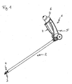
- Fig. 1 is a complete surgical Instrument according to a preferred embodiment of the Invention shown in a perspective view.
- the Accordingly, surgical instrument according to the invention a multifunctional instrument grip 1 attached to a proximal end or end portion of a preferably made stainless steel, a steel alloy or a Plastic material manufactured tubular shaft 2 arranged is, as well as one equipped with an effector 3 or equipable instrument head 4, which at the other, distal end of the tubular shaft 2 is provided.
- the instrument head 4 is at the respective Rohrschaftende stored so that it with respect to the Pipe shaft 2 can be pivoted or angled, whereas the effector 3 in each Abwinkel position of Instrument head 4 rotated about its longitudinal axis or can be rotated, the two aforementioned Movements by means of the instrument handle 1 executable are.
- a number of Handle and / or operating mechanisms provided, the via appropriate gear trains within the Instrument handle 1 and the tubular shaft 2 with the Instrument head 4 and the effector 3 are operatively connected, to the individual movements of the instrument head 4 and the Effectors 3 independently of each other, i. decoupled to be able to execute.
- the instrument handle 1 consists of an ergomisch molded handle 5, the pivoting or tilting on Tube shaft 2 is mounted and on which a first handle 6, in the present case preferably in the form of a knob and a second handle 7, in the present case preferably in the form of a Handle levers are stored.
- a first handle 6, in the present case preferably in the form of a knob and a second handle 7, in the present case preferably in the form of a Handle levers are stored.
- the Instrument grip 1 according to the preferred Overall embodiment of the present invention three operating mechanisms for three independent movements or on the instrument head 4.
- the instrument handle 1 may also have fewer actuation possibilities, For example, only one actuating mechanism for each Swiveling the instrument head 4 and turning the Effectors 3.
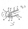
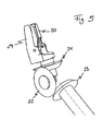
- the illustrated in Fig. 2 idealized handle 5 is about one with the handle 5 on one below described coupling 37 connected link element 8 in Shape of a rotary shaft or turntable with the tubular shaft. 2 pivotally connected.
- the rotary shaft 8 preferably perpendicular to the tubular shaft 2 and the Handle 5 aligned and spaced the handle 5 from the tubular shaft 2 such that this substantially pivoted parallel to the tubular shaft 2 past this can be.
- the rotary shaft 8 is seated at its handle 5 facing End portion rotatably mounted on the connection base 39.
- the rotary shaft 8 on the inside via a predetermined axial length on an inner diameter drilled, which is so much larger than the outer diameter of the terminal socket 39, that between this and the Rotary shaft 8 at least a clearance fit arises.
- Hir notebook becomes at the drilled Innwandung the rotary shaft 8 a Peripheral surface formed with regardssimmtem radius, from the a radially extending pin 40 projects through a Radial through hole from the shell side of the rotary shaft 8 is inserted inwards.
- the instrument handle 1 is now about its pivot axis (corresponds to the central axis of the rotary shaft 8) pivoted, is the pivoting movement on the frictionally engaged on the Peripheral sliding surface of the terminal socket 39 or the Rotary shaft 8 sitting Federings 38 on the in the Federingspalt protruding pin 40 and thus on the rotary shaft 8 or the connecting piece 39 transmitted, which (r) itself thus integral with the instrument handle 1 rotates.
- the maximum transmissible torque is determined by the biasing force with which the springing 38 on the Peripheral sliding surface is placed. As soon as this torque is exceeded, the Federing 38 begins on the To slide circumferential sliding surface, whereby the relative Rotational position between the instrument handle 1 and the Rotary shaft 8 changed.
- the spring washer 38 of course also in corresponding circumferential guides for example in the form of internal and / or external grooves the rotary shaft 8 and / or the connection socket 39 can be snapped to have an axial guidance.
- the rotary shaft 8 which has a central through-passage 9 for receiving subsequently described transmission parts is formed, is at its one, the tubular shaft 2 facing End face with a slotted guide 10 in the form of a cam-shaped groove formed in the a driving pin 11 engages, which is mounted on a tubular shaft 2, axially displaceable torque tube 12 is attached.
- the groove 10 is designed such that during a rotational movement the rotary shaft 8 by corresponding pivoting of the Handle 1 of the driving pin 11 in the groove 10 along slides while doing a compulsory balancing move in Longitudinal direction of the tubular shaft 2 executes on the Push tube 12 is transmitted and depending on the direction of rotation of the Rotary shaft 8 to a reciprocating motion of the torque tube 12th within the tubular shaft 2 leads.
- the backdrop element 8 facing away from the distal end portion the push tube 12 is provided with a longitudinally extending Tab 13 formed over the distal end of the Thrust tube 12 protrudes and at its free end portion Hinge or hinge eyes 14 forms. Furthermore, it is the end face of the tubular shaft 2 at its distal End portion at an angle of preferably 45 ° bevelled and formed with lateral hinge eyes 15, where the instrument head 4 pivotally over Articulated pivot or pins is articulated. This one exists likewise from a pipe section 16, whose one end face, at the Anlenk Hampshire 17 for connection to the tubular shaft.
- the hinge eyes 15 are formed, also in an angle of preferably 45 ° is tapered and that in such a way that after angling of the instrument head 4 on the tubular shaft 2, the two aforementioned slopes complement and angling of the pipe section 16 with respect to the Tube shaft 2 by about 90 °, preferably 70 ° allow.
- a hinge or hinged eyelets 18th educated on the beveled end of the Pipe piece 16 .
- a housing or a receptacle for the Effector 3 Regardless of what type of effector it is that is, regardless of whether as an effector
- a needle holder, a gripper, a pair of pliers or scissors is used, this one has preferably hollow axis of rotation 20, which in the pipe section 16 of the instrument head 4 is rotatably inserted and against an axial movement is secured.
- this Rotation axis 20 is chosen so that this approximately in the region of the pivot axis of the instrument head 4 ends and at its free, projecting to this pivot axis end is provided with a driven spur gear 21 which rotatably is attached to the axis of rotation 20 of the effector 3.
- a driven spur gear 21 which rotatably is attached to the axis of rotation 20 of the effector 3.
- the pivot axis of Instrument head 4 by a dash line through the eyelets 15 is shown.
- Torque transmission spur gear 22 is located on the pivot axis of the instrument head 4 a Torque transmission spur gear 22, which at one of the two pivot pins of not shown Instrument head 4, which dargestelle the idealized Form pivot axis, rotatably mounted and with the output spur gear 21 is in mesh.
- the torque transmission spur gear 22 is in turn with a drive spur gear 23 in combing engagement, which on one within the push tube 12 (not shown in FIGS. 4 and 5) rotatably guided drive shaft 24 is rotatably mounted, as shown in particular in FIG. 4.
- FIG. 4 another Torque introduction spur gear 25 rotationally fixed, which is in mesh with a gear shaft 26, the in which formed within the link element 8 central passageway 9 is mounted.
- the link element 8 is not further in FIG. 4 shown.
- the gear shaft 26 is finally with a Actuating shaft 27, or a spur gear attached thereto 28 within the handle 5 in mesh, which with the one handle, in this case the knob 6, fixed connected is.
- knob 6 forms the knob 6, the distal tip or the outer end of the Instrument grip 1. He is doing rotatably with the Actuating shaft 27 connected, which is substantially along the longitudinal axis of the handle 5 extends.
- Knob 6 has an idealized in FIG. 4 as Sleeve shown handle 5 facing the rear Edge portion which slidably rests on the handle 5 and so that the handle 5 seals at its distal end.
- the knob 6 is doing in an advantageous manner with the fingers in particular with Thumb and forefinger the operator hand presses while the handle 5 is held in hand. It is thus possible to generate any rotation on the effector 3, without the operator embrace the handle 5 itself got to.
- the fingers of a human hand are able very fine motor work and also the fingertips are provided with a variety of nerve endings that one enable pronounced tactile feeling. Accordingly, should Movements that require high accuracy with the Fingers are executed.
- the drive shaft 24 and the torque tube 12 in Axial direction are mounted relatively movable to each other. That a by pivoting the instrument handle. 1 Although triggered rotation of the link element 8 causes a Translational movement of the push tube 12. At the same time however, the drive shaft 24 is in position, i. in Held mesh with the gear shaft 26, whereby the Thrust tube 12 an axial relative movement to the tubular shaft. 2 as well as the drive shaft 24 performs.
- the effector 3 is in the present Embodiment of the invention as a pair of pliers with a fixed as well as a movable, i. swiveling Jaw 29; 30 formed.
- the fixed one Pincer jaw 29 forms together with the rotary shaft 20th of the effector 3 is a unit and is preferably formed integrally with the rotary shaft 20, whereas the movable jaw 30 is at one end pivotally hinged to the fixed jaw 29 is.
- the movable jaw 30 forms an articulation point 31 for a push pin 32, within the rotation shaft 20 is mounted relatively displaceable, so that by the Axial displacement a pivotal movement of the movable Pliers jaw 30 causes the greatest possible translation becomes.
- the thrust pin 32 is, as in particular in the Fig. 6a - 6c is shown, by means of a spring 33 axially biased in the opening direction of the pliers inside the axis of rotation 20 surrounds the push pin 32. Therefor the thrust pin 32 forms a shaft shoulder on which the biasing spring 33 is supported at one end. The other end of the biasing spring 33 is against the fixed Jaw 29 supported.
- One from the axis of rotation 20 in Direction to the pivot axis of the instrument head. 4 outstanding end piece 34 of the thrust pin 32 is formed spherical head, wherein the radius of the Ball head 34 present preferably about 2.5 mm.
- the above drive shaft 24 for the rotor Driving the mounted in the instrument head 3 effector. 3 is with a substantially continuous axial bore (not shown) provided.
- a push rod 35 axially displaceable, as well as relative to Drive shaft 24 rotatably guided, whose the thrust pin 32nd facing end side corresponding to the bevels of tube side as well as push tube sides distal End faces i. preferably 45 ° in the same direction is bevelled.
- the push pin 32 is by means of the spring 33 against this beveled end face of the push rod 35th biased and comes with this in plant.
- Fig. 6a are the push pin 32 as well as the push rod 35 in the event that the Angulation of the instrument head 4 with respect to the Tube shaft 2 is substantially 0 °, axially to each other aligned.
- the thrust pin 32 is in positioned in this position of the instrument head 4, that the center of the ball head 34 of the thrust pin 32nd is approximately in the pivot axis of the instrument head 4.
- the push rod 35 is at its proximal end via a not shown in detail gear 36 with the Actuator lever 7 connected, as the input of this Description has already been made briefly, swiveling on Grip 5 is mounted.
- a rotation of the stored in the instrument head 4 Effector 3 is done by an actuation of the at one end of the handle 5 mounted rotary head 6, wherein the Knob 6 as already stated above, so far can be rotated about its axis of rotation, that is about 360 ° Rotation at the effector 3 is realized without the Handle 5 necessarily must be reversed.
- This rotational movement is via the actuating shaft 27 the gear shaft 26 transmitted, which in turn their Rotary movement on the inside of the torque tube 12th extending drive shaft 24 continues.
- the rotational movement the drive shaft 24 causes a rotational movement of the Transmission spur gear 22, which is the pivot axis of the Instrument head 4 virtually bridged and thus one Rotational movement of the effector 3 within the pipe section 16 of the instrument head 4 triggers the pipe section axis.
- the rotation of the link element 8 is on the backdrop or groove 10 on the front side of the element 8 and the Driving pin 11 in an axial movement of the torque tube 12th transferred, the over the hinged rocker arm 19 to a pivoting movement of the instrument head 4 about the Swivel axis is transformed.
- This pivoting movement but inevitably performs the output spur gear 21, which is fixed to the axis of rotation of the effector 3 and is in mesh with the transfer spur gear 22.
- the transmission spur gear 22 at this Type of actuation i. the pivoting operation, would the pivotal movement of the instrument head 3 a co-rolling of the driven spur gear 21 on the Transmission spur 22 effect and thus inevitably a superimposed rotational movement of the effector. 3 to lead.
- the Gear shaft 26 during a pivoting movement of the handle fifth co-rotated with the link element 8 and drives while the drive shaft 24 within the torque tube 12 at.
- the translation between the gear shaft 26 and the Drive shaft 24 is calculated so that the Transmission gear 22 through the drive shaft 24 to a such rotation angle is rotated, the rotation angle corresponds, which by the output gear 21 at a corresponding bend of the instrument head. 4 caused, causing both rotations due compensate for their opposition.
- Constellation will be the relative position between the Transmission spur gear 22 and the output spur gear 21 also during the bending movement of the instrument head 4 maintain, so that the effector 3 in each Abwinkelungsposition of the instrument head 4 or during a bending movement in its momentary Rotation position with respect to the instrument head 4 is held.
- the clutch 37 in the present case in the form of a slip clutch only one transmit predetermined maximum torque.
- This maximum torque is chosen so that it is in normal use of the instrument should not be exceeded can.
- the maximum angle position as well as the maximum Elongated position of the instrument head 4 is by a Stop mechanism of the hinge between the Instrument head 4 and the tubular shaft 2 defines how this has already been described above. As soon as the Instrument head 4 has reached these positions is a further bending the instrument head 4 in the appropriate direction no longer possible.
- This structural design can be in an advantageous Way for pre-definable adjustment of the relative position of the handle 5 with respect to the tubular shaft 2, i. to exploit so-called zero point adjustment.
- the instrument head 4 in one or the other angled maximum stop position. After the corresponding stop position is reached exercises the Operator person an additional pivoting force on the Instrument grip 1 off, as long as that out of it resulting torque is the maximum transferable Torque of the clutch 37 exceeds.
- the terminal socket 39 slides inside the rotary shaft 8 which reduces the original angular position of the Instrument handle 1 with respect to the tubular shaft 2 for the selected maximum stop position of the Instrument head 4 changed.
- pivotally mounted lever 7 is provided.
- the lever 7 via a not further illustrated deflection gear or a corresponding hinge mechanism with the in the rotary shaft 24 mounted push rod 35 operatively connected, which is at a corresponding actuation of the lever 7 relative to Rotary shaft 24 axially reciprocated.
- a simpler one Bowden cable or a lever would be for one Power transmission to the push rod 35 conceivable.
- FIG. 6 a now shows the relative position of the push rod 35 and the thrust pin 32 in 0 ° -Abwinkelposition of Instrument head 4 with open forceps
- Fig. 6b shows the relative position of the push rod 35 and the push pin 32nd in about 45 ° -Abwinkel position of the instrument head 4 at opened pliers
- Fig. 6c shows the relative position of the Push rod 35 and the push pin 32 in about 45 ° -Abwinkelposition of the instrument head 4 when closed Pliers.
- the push rod 35 is at a Abwinkelungsposition> 0 ° according to the Fig. 6b in Closing direction of the effector 3 shifted, as shown in the Fig. 6c is shown slides the bevelled End face of the push rod 35 along the bolt head 34 over and thereby exerts a feed force on the thrust pin 32nd accordingly, in the closing direction of the Effectors 3 moves.
- the invention relates to a surgical instrument with an instrument handle (1) attached to a proximal End portion of a tubular shaft (2) is hinged, at the distal end portion an instrument head (4) angled is hinged, in which an effector (3) rotatably supports, the has at least one pivotable engagement member (30).
- the Instrument handle (1) has a number of handles and / or actuating mechanisms for actuating the Instrument head (4) and / or the effector (3) via Gear trains on.
- the invention is in the Abwinkelhognos the instrument head (4) effect Gear train a clutch (37) interposed, the one at least over a predetermined pivoting range of Instrument handle (1) Individual zero point adjustment allowed.
- the zero point is defined as one Relative position of the instrument handle (1) with respect to the Tubular shaft (2), in which the instrument head (4) a predetermined angle position with respect to the tubular shaft (2) occupies.
Abstract
Description
Die vorliegende Erfindung betrifft ein chirugisches
Instrument für die minimal invasive Chirurgie gemäß dem
Oberbegriff des Patentanspruchs 1.The present invention relates to a surgical
Instrument for minimally invasive surgery according to the
Preamble of
Aus der DE 100 36 108 ist ein chirugisches Instrument dieser Gattung bekannt. Dieses besteht im wesentlichen aus einem Rohrschaft, an dessen einem proximalen Ende ein Instrumentengriff angeordnet ist, mittels dem ein an dem gegenüberliegenden distalen Ende des Rohrschafts angeordneter Instrumentenkopf über Getriebezüge betätigbar ist. Der Instrumentenkopf läßt sich bezüglich des Rohrschafts verschwenken bzw. neigen und trägt zudem einen drehbar im Instrumentenkopf gelageren Effektor in Form einer Art Zange oder Greifer, deren eines Zangenst ück schwenkbar am Effektor gelagert und mittels des Instrumentengriffs ebenfalls betätigbar ist.From DE 100 36 108 is a surgical instrument known to this genus. This consists essentially of a tubular shaft, at a proximal end of a Instrument handle is arranged by means of a on the opposite distal end of the tubular shaft arranged instrument head via gear trains operable is. The instrument head can be compared with the Pipe shaft pivot or tilt and also contributes one rotatable in the instrument head mounted effector in shape a kind of pliers or gripper, one of which pliers pivotally mounted on the effector and by means of Instrument handle is also actuated.
Konkreter ausgedrückt ermöglichen die Getriebezüge, dass zumindest eine erste Bewegung des Instrumentengriffs, gemäß diesem Stand der Technik auslösbar durch die Handrotation einer Bedienerperson, in eine Rotation des Effektors unter einem bestimmten Übersetzungsverhältnis zu dieser Betätigungsbewegung transformiert wird. Hierdurch ist es möglich, den Effektor trotz der relativ eingeschränkten Bewegungsmöglichkeit einer menschlichen Hand um beispielsweise bis zu 300° zu drehen und damit komplizierte Bewegungsabläufe ohne Umgreifen am Handgriff zu realisieren. Des weiteren wird eine zweite Bewegung des Instrumentengriffs, beispielsweise dessen Abwinkeln bezüglich des Rohrschafts, in eine Neigungsbewegung des Instrumentenkopfs umgesetzt.More specifically, the gear trains allow that at least a first movement of the instrument handle, according to This prior art triggered by the hand rotation an operator person, into a rotation of the effector a certain gear ratio to this Actuating motion is transformed. This is it possible, the effector despite the relatively limited Movement possibility of a human hand around For example, to turn up to 300 ° and thus complicated Movements without gripping the handle too realize. Furthermore, a second movement of the Instrument handle, such as its angling with respect to the tubular shaft, in a tilting motion of the Implemented instrument head.
Die Getriebezüge innerhalb des Instrumentengriffs und des Rohrschafts sind derart ausgelegt, dass eine weitestgehend entkoppelte Betätigung jeder einzelnen Bewegung des Instrumentenkopfs sowie des Effektors ermöglicht wird. Allderdings sind derartige Getriebe zwangsläufig äußerst kompliziert und benötigen demzufolge auch ausreichend Bauraum. Darüber hinaus ist eine vollständige Entkopplung der einzelnen Bewegungen nicht gänzlich gewährleistet.The gear trains within the instrument handle and the The tubular shaft is designed to be as far as possible decoupled actuation of each individual movement of the Instrument head and the effector is possible. However, such transmissions are inevitably extreme complicated and therefore also need sufficient Space. In addition, a complete decoupling the individual movements are not completely guaranteed.
Auch hat es sich gezeigt, dass insbesondere bei einer Handrotation zum Drehen des im Instrumentenkopf gelagerten Effektors, bedingt durch die natürliche Handkonstruktion und der daraus resultierenden Bewegungsabläufe, d.h. unabhängig davon, ob die Getriebezüge des chirurgischen Instrumentes tatsächlich vollständig entkoppelt sind oder nicht, gleichzeitig auch ein geringfügiges Abwinkeln der Instrumentenspitze und darüber hinaus ein Abkippen des gesamten Instrumentenschafts bewirkt wird, wodurch sich die Handhabung des Instuments erheblich erschwert.Also, it has been shown that especially in a Hand rotation for turning the instrument head Effectors, due to the natural hand construction and the resulting motion sequences, i. regardless of whether the gear trains of the surgical Instrumentes are actually completely decoupled or not, at the same time a slight bending of the Instrument tip and beyond tipping the whole instrumental shaft is effected, whereby the Handling the instrument considerably more difficult.
Angesichts dieses Stands der Technik ist es eine Aufgabe der vorliegenden Erfindung, ein chirugisches Instrument dieser Gattung zu schaffen, bei welchem Bewegungen eines Instrumentenkopfs sowie eines Effektors weitestgehend unabhängig von natürlichen Gegebenheiten einer natürlichen Handkonstruktion voneinander entkoppelt über einen Instrumentengriff ausführbar sind.In view of this state of the art, it is a task of the present invention, a surgical instrument to create this type, in which movements of a Instrument head and an effector as far as possible regardless of natural conditions of a natural Hand construction decoupled from each other via a Instrument handle are executable.
Diese Aufgabe wird durch ein chirugisches Instrument mit
den Merkmalen gemäß dem Patentanspruch 1 gelöst.This task is accompanied by a surgical instrument
the features solved according to
Grundsätzlich sind die einzelnen Freiheitsgrade sowie die Bewegungsbereiche einer menschlichen Hand aufgrund ihrer Konstruktion in einem eingeschränkten Bereich vorgegeben und weichen individuell auch nur geringfügig voneinander ab. Der Einsatz eines gattungsgemäßen chirurgischen Instruments kann jedoch oftmals keine Rücksicht auf kinematische Beschränkungen der menschlichen Hand nehmen. In anderen Worten ausgedrückt erfordert ein optimaler Einsatz des chirurgischen Instruments ein Handstellung oder ein Position des Chirurgen, welche ggf. unnatürlich ist. Dies führt dazu, dass solche Stellungen nicht lange und nur mit großem Kraftaufwand gehalten werden können, so dass darüber hinaus in solchen Stellungen ein exaktes Arbeiten mit dem chirurgischen Instrument nur sehr schwer möglich ist.Basically, the individual degrees of freedom and the Ranges of movement of a human hand due to their Design specified in a restricted area and also differ only slightly from each other individually from. The use of a generic surgical However, Instruments can often ignore Take kinematic restrictions of the human hand. In other words, it requires an optimal one Use of the surgical instrument a hand position or a position of the surgeon, which may be unnatural. As a result, such positions are not long and only can be held with great effort, so that in addition, in such positions an exact work with the surgical instrument very difficult is.
Auf diesen Überlegungen basierend besteht der Kern der Erfindung nunmehr darin, den Instrumentengriff über eine Kupplung mit dem Rohrschaft schwenkbar zu verbinden oder besser ausgedrückt, in den Getriebezug zur Übertragung einer Schwenkbewegung des Instrumentengriffs auf den Instrumentenkopf für dessen Abwinklung eine Kupplung zwischenzufügen, die eine zumindest über einen vorbestimmten Bereich individuelle Nullpunkteinstellung erlaubt, wobei der Nullpunkt eine Relativposition des Instrumentengriffs bezüglich des Rohrschafts ist, in der der Instrumentenkopf eine vorbestimmte Abwinkelposition, vorzugsweise die maximale oder minimale Abwinkelposition (Anschlagsposition) bezüglich des Rohrschafts einnimmt.Based on these considerations, the core of the Invention now therein, the instrument handle on a Coupling with the tubular shaft to connect pivotally or better expressed, in the gear train for transmission a pivoting movement of the instrument handle on the Instrument head for its angling a clutch to intervene, one at least over one predetermined range individual zero point adjustment allowed, wherein the zero point is a relative position of the Instrument grip with respect to the tubular shaft is in the the instrument head a predetermined Abwinkelposition, preferably the maximum or minimum angle position (Stop position) with respect to the tubular shaft occupies.
Durch diese technische Maßnahme kann der Instrumentengriff bzw. dessen Relativlage zum Rohrschaft in Abhängigkeit von der Einsatzlage des Instruments so ausgerichtet werden, dass der Chirurg den Instrumentengriff im wesentlichen innerhalb des natürlichen Bewegungsbereichs seiner Hand ergreifen und betätigen kann. Ein ermüdungsfreies und exaktes Arbeiten mit dem erfindungsgemäßen chirurgischen Instrument wird somit möglich.Through this technical measure, the instrument handle or its relative position to the tubular shaft in dependence on the insertion position of the instrument are aligned that the surgeon essentially grasps the instrument handle within the natural range of motion of his hand can seize and press. A fatigue-free and exact working with the inventive surgical Instrument becomes possible.
Vorteilhaft ist es, die Kupplung selbstauslösend auszubilden. D. h. ein solche Kupplung rückt selbsttätig bei Überschreiben eines vorbestimmten Drehmoments aus bzw. überträgt nur dieses vorbestimmte Drehmoment und beginnt darüber hinaus zu gleiten.It is advantageous, the clutch self-triggering train. Ie. Such a coupling is automatically added Overwriting a predetermined torque from only transmits this predetermined torque and starts beyond that.
Eine vorteilhafte Möglichkeit der konstruktiven Augestaltung einer selbstauslösenden Kupplung ist die Ausbildung einer Rutschkupplung, welche prinzipiell zwei gegeneinander gedrückte Drehmomentübertragungselemente vorsieht, welche ab einem bestimmten Drehmoment aneinander abgleiten. Konkret sind die Drehmomentübertragungselemente so gegeneinander vorgespannt, dass sie ein Drehmoment im Rahmen eines herkömmlichen Einsatzes des Instruments durch entsprechenden Reibkontakt übertragen können, welches jedoch für den Fall, dass der Instrumentenkopf sich in seiner maximalen oder minimalen Abwinkelungs-Anschlagsposition befindet, durch weiteres Schwenken des Instrumentengriffs überschritten und damit die Relativlage beider Drehmomentübertragungselemente verändert wird.An advantageous possibility of constructive Design of a self-releasing clutch is the Formation of a slip clutch, which in principle two against each other pressed torque transmission elements provides, which from a certain torque to each other slide. Specifically, the torque transmission elements so biased against each other that they have a torque in the Frame of conventional use of the instrument corresponding frictional contact can transmit, which however, in the event that the instrument head is in its maximum or minimum angular abutment position is located, by further pivoting of the Instrument handle exceeded and thus the relative position Both torque transmission elements is changed.
Alternativ hierzu ist es natürlich auch möglich, zwei Drehmomentübertragungselemente der Kupplung manuell für eine Nullpunkteinstellung außer Eingriff zu bringen, wobei in diesem Fall jedoch die Einhaltung der vorbestimmten Position des Instrumentenkopfs für eine gezielte Einstellung des Nullpunkts sichergestellt sein muß.Alternatively, it is of course possible, two Torque transmission elements of the clutch manually for to disengage a zero point adjustment, wherein in this case, however, compliance with the predetermined Position of the instrument head for a targeted Setting the zero point must be ensured.
Als eine weitere Alternative für eine selbstauslösende Kupplung kann kann auch ein Eingriffselement bspielsweise in Form zumindest eines Mitnehmerzahns oder zumindest einer Kugel vorgesehen sein, das an einem der Drehmomentübertragungselemente gelagert und gegen das andere Drehmomentübertragungselement federvorgespannt ist und in eine Ausnehmung oder Hinterschneidung eingreift. Hierdurch wird eine Formschlußverbindung geschaffen, welche bei Überschreiten eines durch die Federvorspannung bestimmten Drehmoments gelöst wird und sich die beiden Drehmomentübertragungselements relativ verdrehen.As another alternative for a self-triggering Coupling can also be an engaging element bspielsweise in the form of at least one driver tooth or at least one Ball be provided on one of the Torque transmission elements mounted and against the another torque transmitting element is spring-biased and engages in a recess or undercut. As a result, a positive connection is created, which when exceeding one by the spring preload certain torque is released and the two Turn torque transmission element relatively.
Eine weitere vorteilhafte Ausgestaltung der Erfindung sieht vor, die Kupplung im Bereich der Anlenkstelle zwischen dem Instrumentengriff und dem Rohrschaft anzuordnen. Dies hat den Vorteil, dass bei der Dimensionierung der Kupplung geringere räumliche Beschränkungen herrschen, da sich dieser Abschnitt des Instruments grundsätzlich immer außerhalb des zu operierenden Körpers befindet und zudem dieser Bereich für eine sichere Handhabung ohnehin groß gebaut ist entsprechend den Abmessungen einer menschlichen Hand.A further advantageous embodiment of the invention provides before, the coupling in the region of the articulation between the Instrument handle and the tubular shaft to arrange. this has the advantage that when dimensioning the coupling lower spatial restrictions prevail because this section of the instrument basically always located outside of the body to be operated and also this area for safe handling anyway great is built according to the dimensions of a human Hand.
Weitere vorteilhafte Ausgestaltungen der Erfindung sind Gegenstand der Unteransprüche.Further advantageous embodiments of the invention are Subject of the dependent claims.
Die Erfindung wird nachstehend anhand eines bevorzugten
Ausführungsbeispiels unter Bezugnahme auf die begleitenden
Zeichnungen näher erläutert.
In der Fig. 1 ist ein vollständiges chirurgisches
Instrument gemäß einem bevorzugten Ausführungsbeispiel der
Erfindung in einer Perspektivenansicht dargestellt. Das
erfindungsgemäße chirurgische Instrument hat demzufolge
einen multifunktionalen Instrumentengriff 1, der an einem
proximalen Ende oder Endabschnitt eines vorzugsweise aus
nichtrostendem Stahl, einer Stahllegierung oder einem
Kunststoffmaterial gefertigten Rohrschafts 2 angeordnet
ist, sowie einem mit einem Effektor 3 bestückten oder
bestückbaren Instrumentenkopf 4, der an dem anderen,
distalen Ende des Rohrschafts 2 vorgesehen ist.In Fig. 1 is a complete surgical
Instrument according to a preferred embodiment of the
Invention shown in a perspective view. The
Accordingly, surgical instrument according to the invention
a
Generell ist der Instrumentenkopf 4 an dem betreffenden
Rohrschaftende so gelagert, dass er bezüglich des
Rohrschafts 2 verschwenkt bzw. abgewinkelt werden kann,
wohingegen der Effektor 3 in jeder Abwinkel position des
Instrumentenkopfs 4 um dessen Längsachse gedreht bzw.
rotiert werden kann, wobei die beiden vorstehend genannten
Bewegungen mittels des Instrumentengriffs 1 ausführbar
sind. Hierzu sind am Instrumentengriff 1 eine Anzahl von
Handhaben und/oder Betätigungsmechanismen vorgesehen, die
über entsprechende Getriebezüge innerhalb des
Instrumentengriffs 1 sowie des Rohrschafts 2 mit dem
Instrumentenkopf 4 bzw. dem Effektor 3 wirkverbunden sind,
um die einzelnen Bewegungen des Instrumentenkopfs 4 und des
Effektors 3 unabhängig voneinander, d.h. entkoppelt
ausführen zu können.In general, the
Konkret besteht der Instrumentengriff 1 aus einem ergomisch
geformten Griffstück 5, das schwenk- bzw. neigbar am
Rohrschaft 2 montiert ist und an dem eine erste Handhabe 6,
vorliegend vorzugsweise in Form eines Drehknopfs sowie eine
zweite Handhabe 7, vorliegend vorzugsweise in Form eines
Griffhebels gelagert sind. Somit besitzt der
Instrumentengriff 1 gemäß dem bevorzugten
Ausführungsbeispiel der vorliegenden Erfindung insgesamt
drei Betätigungsmechanismen für drei unabhängige Bewegungen
des bzw. am Instrumentenkopf 4. An dieser Stelle sei
ausdrücklich darauf hingewiesen, dass der Instrumentengriff
1 auch weniger Betätigungsmöglichkeiten aufweisen kann,
etwa jeweils nur einen Betätigungsmechanismus für ein
Verschwenken des Instrumentenkopfs 4 und Drehen des
Effektors 3.Specifically, the
Der äußere Aufbau des Instrumentengriffs 1 insbesondere mit
Bezug auf den Betätigungsmechanismus für ein Verschwenken
bzw. Abwinkeln des Instrumentenkopfs 4 sowie den
zugehörigen Abwinklungs-Getriebezug ist in den Fig. 2 und 3
dargestellt.The outer structure of the instrument handle 1 in particular with
Referring to the operating mechanism for pivoting
or bending the
Das in Fig. 2 idealisiert dargestellte Griffstück 5 ist
über ein mit dem Griffstück 5 über eine nachfolgend noch
beschriebene Kupplung 37 verbundenes Kulissenelement 8 in
Form einer Drehwelle oder Drehscheibe mit dem Rohrschaft 2
schwenkbar verbunden. Hierbei ist die Drehwelle 8
vorzugsweise senkrecht zum Rohrschaft 2 sowie zum
Griffstück 5 ausgerichtet und beabstandet das Griffstück 5
vom Rohrschaft 2 derart, dass dieses im wesentlichen
parallel zum Rohrschaft 2 an diesem vorbei verschwenkt
werden kann.The illustrated in Fig. 2 idealized
An dem Griffstück 5 selbst ist eine Art rohr- oder
hülsenförmiger Anschlusssockel 39 an dessen proximalem
Endabschnitt fixiert, der sich im wesentlichen senkrecht,
d.h. in Radialrichtung vom Griffstück 5 weg erstreckt. Der
rohrförmige Anschlusssockel 39 ist an seinem freien Ende
mit einer äußeren Gleitfläche (nicht näher dargestellt)
ausgebildet, auf die ein offener Federring 38 unter
Spannung aufgesetzt ist.On the
Die Drehwelle 8 sitzt an ihrem dem Griffstück 5 zugewandten
Endabschnitt auf dem Anschlusssockel 39 drehbar auf.
Hierfür ist die Drehwelle 8 innenseitig über eine
vorbestimmte axiale Länge auf einen Innendruchmesser
aufgebohrt, der soviel größer ist als der Außendurchmesser
des Anschlusssockels 39, dass zwischen diesem und der
Drehwelle 8 zumindest eine Spielpassung entsteht. Hirdurch
wird an der aufgebohrten Innwandung der Drehwelle 8 eine
Umfangsfläche mit vorbesimmtem Radius ausgebildet, aus der
ein radial verlaufender Stift 40 ragt, der durch eine
radiale Durchgangsbohrung von der Mantelseite der Drehwelle
8 nach Innen eingesteckt ist.The rotary shaft 8 is seated at its
Bei der Montage der Drehwelle 8 wird diese auf den
Anschlusssockel 39 aufgesteckt, bis dass der Federing 38
auf oder an der inneren Umfangsgleitfläche der Drehwelle 8
positioniert ist. Der Stift 40 ragt dabei in den vom
offenen Federing 38 gebildeten Radialspalt und bildet somit
eine Formschlußverbindung zwischen der Drehwelle 8 und dem
Federring 38, welcher wiederum eine Reibschlußverbindung
mit dem Anschlusssockel 39 eingeht. An dieser Stelle sei
jedoch explizit darauf hingewiesen, dass die vorstehende
Kupplung auch in kinematisch umgekehrter Weise ausgebildet
sein kann, d.h. der Federing 38 reibschlüssing in der
Drehwelle 8 sitzen und über einen im Anschlussstutzen
steckenden Stift mit diesem eine Formschlussverbindung
eingehen kann.When mounting the rotary shaft 8, this is on the
Plug-in
Wird der Instrumentengriff 1 nunmehr um seine Schwenkachse
(entspricht der Mittelachse der Drehwelle 8) geschwenkt,
wird die Schwenkbewegung über den reibschlüssig auf der
Umfangsgleitfläche des Anschlusssockels 39 oder der
Drehwelle 8 sitzenden Federings 38 auf den in den
Federingspalt ragenden Stift 40 und damit auf die Drehwelle
8 oder den Anschlussstutzen 39 übertragen, welche(r) sich
somit einstückig mit dem Instrumentengriff 1 mitdreht. Das
maximal übertragbare Drehmoment bestimmt sich dabei durch
die Vorspannkraft, mit welcher der Federing 38 auf die
Umfangsgleitfläche aufgesetzt ist. Sobald dieses Drehmoment
überschritten wird, beginnt der Federing 38 auf der
Umfangsgleitfläche zu gleiten, wodurch sich die relative
Drehposition zwischen dem Instrumentengriff 1 und der
Drehwelle 8 verändert.If the instrument handle 1 is now about its pivot axis
(corresponds to the central axis of the rotary shaft 8) pivoted,
is the pivoting movement on the frictionally engaged on the
Peripheral sliding surface of the
An dieser Stelle sei darauf hingewiesen, dass der Federring
38 natürlich auch in entsprechende Umfangsführungen
beispielsweise in Form von Innen- und/oder Außennuten an
der Drehwelle 8 und/oder dem Anschlusssockel 39
eingeschnappt sein kann, um eine axiale Führung zu haben.At this point it should be noted that the spring washer
38 of course also in corresponding circumferential guides
for example in the form of internal and / or external grooves
the rotary shaft 8 and / or the
Die Drehwelle 8, welche einen zentralen Durchgangskanal 9
zur Aufnahme nachfolgend noch beschriebener Getriebeteile
ausbildet, ist an ihrer einen, dem Rohrschaft 2 zugewandten
Stirnseite mit einer Kulissenführung 10 in Form einer
nockenförmigen Nut ausgebildet, in die ein Mitnehmerstift
11 eingreift, welcher an einem im Rohrschaft 2 gelagerten,
axial verschiebbaren Schubrohr 12 befestigt ist. Die Nut 10
ist dabei derart ausgebildet, dass bei einer Drehbewegung
der Drehwelle 8 durch entsprechendes Schwenken des
Griffstücks 1 der Mitnehmerstift 11 in der Nut 10 entlang
gleitet und dabei eine Zwangs-Ausgleichsbewegung in
Längsrichtung des Rohrschafts 2 ausführt, die auf das
Schubrohr 12 übertragen wird und je nach Drehrichtung der
Drehwelle 8 zu einer Hin- und Herbewegung des Schubrohrs 12
innerhalb des Rohrschafts 2 führt.The rotary shaft 8, which has a central through-passage 9
for receiving subsequently described transmission parts
is formed, is at its one, the
Zusammenhehalten wird der vorstehend beschriebene Aufbau
schließlich durch eine Nabe in Form eines Nabenbolzens
(nicht näher gezeigt), der am Rohrschaft fixiert ist und
die Drehwelle 8 wie auch das Griffstück 5 in dessen
Schwenkachse durchdringt und mittels einer ebenfalls nicht
weiter dargestellen Mutter gekontert ist.Zusammengehhalten the structure described above
finally by a hub in the form of a hub bolt
(not shown in detail), which is fixed to the tubular shaft and
the rotary shaft 8 as well as the
Der dem Kulissenelement 8 abgewandte, distale Endabschnitt
des Schubrohrs 12 ist mit einer längs sich ersteckenden
Lasche 13 ausgebildet, die über das distale Ende des
Schubrohrs 12 vorsteht und an ihrem freien Endabschnitt ein
Scharnier bzw. Scharnierösen 14 bildet. Des weiteren ist
die Stirnseite des Rohrschafts 2 an seinem distalen
Endabschnitt in einem Winkel von vorzugsweise 45°
abgeschrägt und mit seitlichen Gelenkösen 15 ausgebildet,
an denen der Instrumentenkopf 4 schwenkbar über
Gelenkzapfen oder Stifte angelenkt ist. Dieser besteht
ebenfalls aus einem Rohrstück 16, dessen eine Stirnseite,
an der Anlenkösen 17 für ein Verbinden mit dem Rohrschaft 2
bzw. dessen Gelenkösen 15 ausgebildet sind, ebenfalls in
einem Winkel von vorzugsweise 45° abgeschrägt ist und zwar
derart, dass sich nach einem Anlenken des Instrumentenkopfs
4 am Rohrschaft 2 die beiden vorstehend genannten Schrägen
ergänzen und ein Abwinkeln des Rohrstücks 16 bezüglich des
Rohrschafts 2 um ca. 90° vorzugsweise 70° ermöglichen. The backdrop element 8 facing away from the distal end portion
the
Des weiteren ist an der abgeschrägten Stirnseite des
Rohrstücks 16 ein Scharnier bzw. Scharnierösen 18
ausgebildet. An den schubrohrseitigen sowie den
rohrstückseitigen Scharnierösen 14; 18 ist ein Kipphebel 19
jeweils anscharniert, welcher folglich zur Schwenkachse des
Instrumentenkopfs 4 radial nach außen versetzt ist und eine
axiale Translationsbewegung des Schubrohrs 12 auf das
Rohrstück 16 überträgt, wodurch dieses um dessen
Schwenkachse geschwenkt wird.Furthermore, on the beveled end of the
Pipe piece 16 a hinge or hinged eyelets 18th
educated. On the Schubrohrseitige and the
pipe-
Im nachfolgenden wird anhand der Fig. 4 und 5 der
Betätigungsmechanismus für eine Rotation des im
Instrumentenkopf 4 gelagerten Effektors 3 sowie der
zugehörige Rotations-Getriebezug beschrieben.In the following, with reference to FIGS. 4 and 5 of
Actuating mechanism for a rotation of the
Wie noch aus der Fig. 2 zu entnehmen ist, stellt das
vorstehend genannte Rohrstück 16 des Instrumentenkopfs 4
gleichzeitig ein Gehäuse bzw. eine Aufnahme für den
Effektor 3 dar. Unabhängig davon, um welche Art Effektor es
sich dabei handelt, also unabhängig davon, ob als Effektor
beispielsweise ein Nadelhalter, ein Greifer, eine Zange
oder Schere zum Einsatz kommt, besitzt dieser eine
vorzugsweise hohle Rotationsachse 20, die in das Rohrstück
16 des Instrumentenkopfs 4 drehbar eingesetzt und gegen
eine Axialbewegung gesichert ist. Die Länge dieser
Rotationsachse 20 ist dabei so gewählt, dass diese in etwa
im Bereich der Schwenkachse des Instrumentenkopfs 4 endet
und an ihrem freien, zu dieser Schwenkachse ragenden Ende
mit einem Abtriebs-Stirnrad 21 versehen ist, das drehfest
an der Rotationsachse 20 des Effektors 3 befestigt ist.
Insbesondere in der Fig. 2 ist die Schwenkachse des
Instrumentenkopfs 4 durch eine Strich-Linie durch die Ösen
15 dargestellt. As can be seen from Fig. 2, that provides
above-mentioned
Wie aus der Fig. 5 ferner zu entnehmen ist, befindet sich
auf der Schwenkachse des Instrumentenkopfs 4 ein
Drehmoment-Übertragungsstirnrad 22, welches an einem der
beiden nicht weiter dargestellten Schwenkzapfen des
Instrumentenkopfs 4, welche die idealisiert dargestelle
Schwenkachse bilden, drehbar gelagert und mit dem Abtriebs-Stirnrad
21 in Kämmeingriff ist. Das Drehmoment-Übertragungsstirnrad
22 ist wiederum mit einem Antriebs-Stirnrad
23 in Kämmeingriff, welches auf einer innerhalb
des Schubrohrs 12 (in den Fig. 4 und 5 nicht dargestellt)
drehbar geführten Antriebswelle 24 drehfest montiert ist,
wie dies insbesondere in der Fig. 4 gezeigt ist. An einem
dem Antriebs-Stirnrad 23 gegenüberliegenden Ende der
Antriebswelle 24 ist gemäß der Fig. 4 ein weiteres
Drehmoment-Einleitungsstirnrad 25 drehfest angeordnet,
welches mit einer Zahnradwelle 26 in Kämmeingriff ist, die
in dem innerhalb des Kulissenelements 8 ausgebildeten
zentralen Durchgangskanal 9 gelagert ist.As can also be seen from FIG. 5, is located
on the pivot axis of the instrument head 4 a
Torque
Das Kulissenelement 8 ist in der Fig. 4 nicht weiter dargestellt.The link element 8 is not further in FIG. 4 shown.
Die Zahnradwelle 26 ist schließlich mit einer
Betätigungswelle 27, bzw. einem daran befestigten Stirnrad
28 innerhalb des Griffstücks 5 in Kämmeingriff, welche mit
der einen Handhabe, vorliegend dem Drehknopf 6, fest
verbunden ist.The
Wie insbesondere aus der Fig. 4 zu entnehmen ist, bildet
der Drehknopf 6 die distale Spitze oder das äußere Ende des
Instrumentengriffs 1. Er ist dabei drehfest mit der
Betätigungswelle 27 verbunden, welche sich im wesentlichen
entlang der Längsachse des Griffstücks 5 erstreckt. Der
Drehknopf 6 hat einen zum in der Fig. 4 idealisiert als
Hülse dargestellten Griffstück 5 zugewandten hinteren
Randabschnitt, der gleitend am Griffstück 5 anliegt und
damit das Griffstück 5 an seinem distalen Ende abdichtet.As can be seen in particular from FIG. 4, forms
the
Bei einer Betätigung des Drehknopfs 6 wird dessen
Drehbewegung über die Betätigungswelle 27 innerhalb des
Griffstücks 5, die Zahnradwelle 26, die daran sich
anschließende Antriebswelle 24 innerhalb des Schubrohrs 12
sowie das Übertragungsstirnrad 22 auf den Effektor 3
übertragen und dieser gedreht. Der Drehknopf 6 wird dabei
in vorteilhafter Weise mit den Fingern insbesondere mit
Daumen und Zeigefinder der Bedienerhand betätigt, während
das Griffstück 5 in Hand gehalten wird. Es ist somit
möglich, jede beliebige Rotation am Effektor 3 zu erzeugen,
ohne dass der Bediener am Griffstück 5 selbst umgreifen
muss. Die Finger einer menschlichen Hand sind in der Lage,
sehr feinmotorisch zu arbeit und auch die Fingerspitzen
sind mit einer Vielzahl von Nervenenden versehen, die ein
ausgeprägtes taktiles Gefühl ermöglichen. Demnach sollten
Bewegungen, die eine hohe Genauigkeit erfordern, mit den
Fingern ausgeführt werden. Es hat sich gezeigt, dass die
Drehbewegung des Effektors 3 eine solche ist und daher
erfindungsgemäß durch den Drehknopf 6 ausgelöst wird, ohne
dass in vorteilhafter Weise durch das Drehen des Knopfs 6
für eine Rotation des Effektors 3 eine Bewegung auf den
Rohrschaft 2 übertragen wird. Vielmehr kann die Hand einer
Bedienerperson ruhig gehalten werden.Upon actuation of the
An dieser Stelle sei ferner noch darauf hingewiesen, dass
die Antriebswelle 24 sowie das Schubrohr 12 in
Axialrichtung relativ beweglich zueinander gelagert sind.
D.h. eine durch ein Verschwenken des Instrumentengriffs 1
ausgelöste Drehung des Kulissenelements 8 bewirkt zwar eine
Translationsbewegung des Schubrohrs 12. Gleichzeitig wird
jedoch die Antriebswelle 24 in Position, d.h. in
Kämmeingriff mit der Zahnradwelle 26 gehalten, wodurch das
Schubrohr 12 eine axiale Relativbewegung zum Rohrschaft 2
wie auch zur Antriebswelle 24 ausführt.It should also be noted at this point that
the
Schließlich wird nachfolgend der Betätigungsmechanismus für
den Effektor 3, d.h. dessen Funktionen selbst sowie den
zugehörigen Effektor-Getriebezug anhand der Fig. 5 und 6a-6c
beschrieben.Finally, the actuating mechanism for
the
Gemäß der Fig. 5 ist der Effektor 3 in dem vorliegenden
Ausführungsbeispiel der Erfindung als eine Zange mit einer
feststehenden sowie einer bewegbaren, d.h. schwenkbaren
Zangenbacke 29; 30 ausgebildet. Die feststehende
Zangenbacke 29 bildet zusammen mit der Rotationswelle 20
des Effektors 3 eine Einheit und ist vorzugsweise
einstückig mit der Rotationswelle 20 ausgebildet,
wohingegen die bewegbare Zangenbacke 30 an einem Ende
schwenkbar an der feststehenden Zangenbacke 29 angelenkt
ist.According to Fig. 5, the
Die bewegbare Zangenbacke 30 bildet eine Anlenkstelle 31
für einen Schubbolzen 32, der innerhalb der Rotationswelle
20 relativ verschiebbar gelagert ist, sodass durch dessen
Axialverschiebung eine Schwenkbewegung der bewegbaren
Zangenbacke 30 mit möglichst großer Übersetzung bewirkt
wird. Der Schubbolzen 32 ist, wie dies insbesondere in den
Fig. 6a - 6c dargestellt wird, mittels einer Feder 33 axial
in Öffnungsrichtung der Zange vorgespannt, die innerhalb
der Rotationsachse 20 den Schubbolzen 32 umgibt. Hierfür
bildet der Schubbolzen 32 einen Wellenabsatz, an dem sich
die Vorspannfeder 33 an ihrem einen Ende abstützt. Das
andere Ende der Vorspannfeder 33 ist gegen die feststehende
Zangenbacke 29 abgestützt. Ein aus der Rotationsachse 20 in
Richtung zur Schwenkachse des Instrumentenkopfs 4
herausragendes Endstück 34 des Schubbolzens 32 ist
kugelkopfförmig ausgebildet, wobei der Radius des
Kugelkopfs 34 vorliegend vorzugsweise ca. 2.5 mm beträgt.The
Die vorstehend genannte Antriebswelle 24 für das rotorische
Antreiben des im Instrumentenkopf 3 gelagerten Effektors 3
ist mit einer im wesentlichen durchgehenden Axialbohrung
(nicht weiter gezeigt) versehen. In dieser Axialbohrung ist
ein Schubstab 35 axialverschieblich, sowie relativ zur
Antriebswelle 24 drehbar geführt, dessen dem Schubbolzen 32
zugewandte Stirnseite entsprechend den Abschrägungen der
rohrschaftseitigen wie auch schubrohrseiten distalen
Stirnseiten d.h. vorzugsweise 45° in die selbe Richtung
abgeschrägt ist. Der Schubbolzen 32 ist mittels der Feder
33 gegen diese abgeschrägte Stirnfläche des Schubstabs 35
vorgespannt und kommt mit dieser in Anlage. Dabei ist die
Anlagefläche zwischen dem Schubstab 35 und dem Schubbolzen
32 aufgrund der vorstehend beschriebenden Kugelkopfform des
Bolzens 32 im wesentlichen punktförmig und zwar unabhängig
von dem Abwinkelungsgrad des Instrumentenkopfs 4 sowie
unabhängig von der Rotationsposition des Effektors 3.The
Wie aus der Fig. 6a zu erkennen ist, sind der Schubbolzen
32 wie auch der Schubstab 35 für den Fall, dass die
Abwinkelung des Instrumentenkopfs 4 bezüglich des
Rohrschafts 2 im wesentlichen 0° beträgt, axial zueinander
ausgerichtet. Darüber hinaus ist der Schubbolzen 32 in
dieser Stellung des Instrumentenkopfs 4 so positioniert,
dass der Mittelpunkt des Kugelkopfs 34 des Schubbolzens 32
in etwa in der Schwenkachse des Instrumentenkopfs 4 liegt.As can be seen from Fig. 6a, are the push pin
32 as well as the
Der Schubstab 35 ist an seinem proximalen Ende über ein
nicht im Einzelnen gezeigtes Getriebe 36 mit dem
Betätigungshebel 7 verbunden, der, wie Eingangs dieser
Beschreibung bereits kurz ausgeführt wurde, schwenkbar am
Griffstück 5 gelagert ist. The
Die Funktionsweise des erfindungsgemäßen chirurgischen Instruments wird nachfolgend im Einzelnen beschrieben.The operation of the inventive surgical Instruments will be described in detail below.
Eine Rotation des im Instrumentenkopf 4 gelagerten
Effektors 3 erfolgt durch eine Betätigung des an einem Ende
des Griffstücks 5 gelagerten Drehkopfs 6, wobei der
Drehknopf 6 wie vorstehend bereits ausgeführt wurde, soweit
um seine Drehachse gedreht werden kann, dass eine ca. 360°
Rotation am Effektor 3 realisiert wird, ohne dass am
Griffstück 5 notwendiger Weise umgegriffen werden muss.
Diese Drehbewegung wird über die Betätigungswelle 27 auf
die Zahnradwelle 26 übertragen, welche wiederum ihre
Drehbewegung auf die innerhalb des Schubrohrs 12
verlaufende Antriebswelle 24 weiter gibt. Die Drehbewegung
der Antriebswelle 24 bewirkt eine Drehbewegung des
Übertragungsstirnrads 22, welches die Schwenkachse des
Instrumentenkopfs 4 quasi überbrückt und damit eine
Rotationsbewegung des Effektors 3 innerhalb des Rohrstücks
16 des Instrumentenkopfs 4 um die Rohrstückachse auslöst.A rotation of the stored in the
Um eine Abwinkelung, d.h. eine Schwenkbewegung des
Instrumentenkopfs 4 und damit des Effektors 3 zu bewirken,
muß gemäß dem vorliegenden Ausführungsbeispiel das gesamte
Griffstück 5 um die Längsachse des Kulissenelements bzw.
die Drehwelle 8 geschwenkt werden. In anderen Worten
ausgedrückt, bewirkt eine Schwenkbewegung des Griffstücks 5
bezüglich des Rohrschafts 2 eine Drehbewegung des über die
Kupplung 37 mit dem Griffstück 5 in Rotationsrichtung
reibschlüssig verbundenen Kulissenelements 8. Gleichzeitig
jedoch wird aufgrund der Tatsache, dass durch den
Kämmeingriff zwischen der Betätigungsachse 27 und der
Zahnradwelle 26 eine Art Selbsthemmung durch Reibung
(Wirkungsgrad des Getriebes) entsteht, welche ggf. durch
leichtes Halten des Betätigungsknopfs 6 sowie durch die
Haftreibung zwischen Betätigungsknopf 6 und Griffstück 1
noch unterstützt wird, die Zahnradwelle 26 mit dem
Kulissenelement 8 mit gedreht.To make a bend, i. a pivoting movement of
Die Drehung des Kulissenelements 8 wird über die Kulisse
bzw. Nut 10 an der Stirnseite des Elements 8 sowie den
Mitnehmerzapfen 11 in eine Axialbewegung des Schubrohrs 12
übertragen, die über den anscharnierten Kipphebel 19 zu
einer Schwenkbewegung des Instrumentenkopfs 4 um dessen
Schwenkachse transformiert wird. Diese Schwenkbewegung
führt jedoch zwangsläufig auch das Abtriebsstirnrad 21 aus,
welches an der Rotationsachse des Effektors 3 fixiert und
mit dem Übertragungsstirnrad 22 in Kämmeingriff ist. Würde
demzufolge das Übertragungsstirnrad 22 bei dieser
Betätigungsart, d.h. der Verschwenkbetätigung, feststehen,
würde die Schwenkbewegung des Instrumentenkopfs 3 ein
gleichläufiges Abrollen des Abtriebsstirnrads 21 an dem
Übertragungsstirnrad 22 bewirken und somit zwangsläufig zu
einer überlagerten Rotationsbewegung des Effektors 3
führen.The rotation of the link element 8 is on the backdrop
or groove 10 on the front side of the element 8 and the
Wie vorstehend jedoch ausgeführt wurde, wird die
Zahnradwelle 26 bei einer Schwenkbewegung des Griffstücks 5
zusammen mit dem Kulissenelement 8 mitgedreht und treibt
dabei die Antriebswelle 24 innerhalb des Schubrohrs 12 an.
Die Übersetzung zwischen der Zahnradwelle 26 und der
Antriebswelle 24 ist dabei so berechnet, dass das
Übertragungszahnrad 22 durch die Anriebswelle 24 um einen
solchen Drehwinkel gedreht wird, der dem Drehwinkel
entspricht, welcher durch das Abtriebszahnrad 21 bei einer
entsprechenden Abwinkelung des Instrumentenkopfs 4
hervorgerufen wird, wodurch sich beide Drehungen aufgrund
ihrer Gegenläufigkeit kompensieren. Bei dieser
Konstellation wird die Relativposition zwischen dem
Übertragungsstirnrad 22 und dem Abtriebsstirnrad 21 auch
während der Abwinkelungsbewegung des Instrumentenkopfs 4
beibehalten, so dass der Effektor 3 in jeder
Abwinkelungsposition des Instrumentenkopfs 4 bzw. während
einer Abwinkelungsbewegung in seiner augenblicklichen
Rotationsposition bezüglich des Instrumentenkopfs 4
gehalten wird.However, as stated above, the
Wie vorstehend bereits ausgeführt wurde, kann die Kupplung
37, vorliegend in Form einer Rutschkupplung nur ein
vorbestimmtes maximales Drehmoment übertragen. Dieses
maximale Drehmoment ist dabei so gewählt, dass es im
normalen Einsatz des Instruments nicht überschritten werden
kann. Die maximale Abwinkelposition wie auch die maximale
Streckposition des Instrumentenkopfs 4 wird durch einen
Anschlagsmechanismus des Scharniers zwischen dem
Instrumentenkopf 4 und dem Rohrschaft 2 definiert, wie dies
vorstehend bereits beschrieben wurde. Sobald der
Instrumentenkopf 4 diese Positionen erreicht hat, ist ein
weiteres Abwinkeln des Instrumentenkopfs 4 in die
entsprechende Richtung nicht mehr möglich.As already stated above, the clutch
37, in the present case in the form of a slip clutch only one
transmit predetermined maximum torque. This
maximum torque is chosen so that it is in
normal use of the instrument should not be exceeded
can. The maximum angle position as well as the maximum
Elongated position of the
Diese konstruktive Ausgestaltung läßt sich in vorteilhafter
Weise zur vorbestimmbaren Einstellung der Relativposition
des Griffstücks 5 bezüglich des Rohrschafts 2 d.h. zur
sogenannten Nullpunkteinstellung ausnutzen. Zu diesem Zweck
wird der Instrumentenkopf 4 in die eine oder andere
maximale Anschlagsposition abgewinkelt. Nach die
entsprechende Anschlagsposition erreicht ist übt die
Bedienerperson eine zusätzliche Schwenkkraft auf den
Instrumentengriff 1 aus, solange, bis das hieraus
resultierende Drehmoment das maximal übertragbare
Drehmoment der Kupplung 37 übersteigt. In diesem Augenblick
gleitet der Anschlusssockel 39 innerhalb der Drehwelle 8
ab, wodurch sich die ürsprüngliche Winkelposition des
Instrumentengriffs 1 bezüglich des Rohrschafts 2 für die
ausgewählte maximale Anschlagsposition des
Instrumentenkopfs 4 verändert.This structural design can be in an advantageous
Way for pre-definable adjustment of the relative position
of the
Um eine Betätigung des Effektors 3 d.h. dessen Funktion
selbst zu bewirken, ist in dem vorliegenden bevorzugten
Ausführungsbeispiel der am Griffstück 5 schwenkbar
gelagerte Hebel 7 vorgesehen. Wie bereits vorstehend zu den
Fig. 6a-6c ausgeführt wurde, ist der Hebel 7 über ein nicht
weiter dargestelltes Umlenkgetriebe oder einen
entsprechenden Gelenkmechanismus mit dem in der Drehwelle
24 gelagerten Schubstab 35 wirkverbunden, welcher sich bei
einer entsprechenden Betätigung des Hebels 7 relativ zur
Drehwelle 24 axial hin- und herbewegt. Auch ein einfacher
Bowdenzug oder ein Umlenkhebel wäre für eine
Kraftübertragung auf den Schubstab 35 denkbar.To prevent actuation of the effector 3 i. its function
to effect itself is in the present preferred
Embodiment of the
Die Fig. 6a zeigt nunmehr die Relativlage des Schubstabs 35
sowie des Schubbolzens 32 in 0°-Abwinkelposition des
Instrumentenkopfs 4 bei geöffneter Zange, die Fig. 6b zeigt
die Relativlage des Schubstabs 35 sowie des Schubbolzens 32
in ca. 45°-Abwinkel position des Instrumentenkopfs 4 bei
geöffneter Zange und die Fig. 6c zeigt die Relativlage des
Schubstabs 35 sowie des Schubbolzens 32 in ca. 45°-Abwinkelposition
des Instrumentenkopfs 4 bei geschlossener
Zange.FIG. 6 a now shows the relative position of the
Wie aus den Fig. 6a-6c zu entnehmen ist, wird der
Schubbolzen 32 durch die Vorspannkraft der Feder 33 in
ständiger Anlage mit der abgeschrägten oder gefasten
distalen Stirnfläche des Schubstabs 35 gehalten. Bei einer
Verschiebung des Schubstabs 35 in Richtung Instrumentenkopf
4 im Fall einer 0°-Abwinkelung des Instrumentenkopfs 4
gemäß der Fig. 6a wird der Schubbolzen 32 mit gleicher
Geschwindigkeit und Wegstrecke wie der Schubstab 35, d.h.
ohne Übersetzung, entgegen der Vorspannkraft der Feder 33
verschoben, wodurch die daran angelenkte Zangenbacke 30 in
Schließrichtung verschwenkt wird.As can be seen from Figs. 6a-6c, the
Pintle 32 by the biasing force of the spring 33 in
permanent plant with the beveled or bevelled
distal end face of the
An dieser Stelle sei darauf hingewiesen, dass durch die
Verschiebetätigkeit des Schubstabs 35 der Schubbolzen 32,
d.h. insbesondere der Mittelpunkt des Bolzenkopfradius nur
annähernd auf der Schwenkachse des Instrumentenkopfs 4
verbleibt, sich also bei einer Abwinkelungsbewegung des
Instrumentenkopfs 4 auf einer Art Kreisbahn bewegt. Wie
jedoch eingangs der Figurenbeschreibung bereits ausgeführt
wurde, sind die Stellwege für ein Öffnen und Schließen
beispielsweise der Zange aufgrund der eingestellten
Übersetzungen so gering, dass der Kreisbahnradius zwar
theoretisch berechenbar ist, jedoch bereits schon aus
fertigungstechnischen Gründen (Eigenelastizität der
verwendeten Materialien, Maßtoleranzen und Spiel an den
Gelenkverbindungen und Getriebeteilen) keinen relevanten
Einfuß auf Zangenstellung hat. In anderen Worten
ausgedrückt, wird die Zangenstellung durch die Position des
Hebels 7 bestimmt, welcher wiederum von einer Bedinerperson
gehalten wird und damit beispielsweise auch
unkontrollierbaren Handbewegungen (Zitterbewegungen)
unterliegt. Derartige aufgrund manueller Betätigungen
erzeugte Störungen sind im Vergleich zu jenen Störungen,
welche durch die vorstehend beschriebene Kreisbahnbewegung
erzeugt werden, wesentlich größer und daher praktisch
alleinig maßgeblich.At this point it should be noted that by the
Shifting action of the
D.h. unabhängig von der aktuellen Position des Schubstabs
35 bzw. des Schubbolzens 32 bewirkt eine Abwinkelung des
Instrumentenkopfs 4 generell nicht nur ein Verschwenken des
Schubbolzens 32 bezüglich des Schubstabs 35 sondern auch
ein geringes Abgleiten des Bolzenkopfs 34 auf der
abgeschrägten Stirnfäche des Schubstabs 35. Durch diese
geringe Abgleitbewegung bleibt der Anlagekontakt des
Schubbolzens 32 auf der Stirnfläche erhalten, wobei jedoch
nur eine solche Ausgleichs-Längsbewegung des Schubbolzens
32 in Folge seiner Abgleitbewegung erfolgt, die zu keiner
praktisch relevanten Veränderung der Schließ- oder
Öffnungsposition am Effektor 3 führt. Gleichzeitig jedoch
wird eine Art Kraftumlenkmechanismus geschaffen, um eine
Längsbewegung des Schubstabs 35 in eine Längsbewegung des
nunmehr im Winkel zum Schubstab 35 stehenden Schubbolzens
32 durch die Abschrägung der Schubstab-Stirnfläche zu
bewirken.That regardless of the current position of the
In anderen Worten ausgedrückt, wird der Schubstab 35 bei
einer Abwinkelungsposition > 0° gemäß der Fig. 6b in
Schließrichtung des Effektors 3 verschoben, wie dies in der
Fig. 6c dargestellt ist, gleitet die abgeschrägte
Stirnfläche des Schubstabs 35 längs am Bolzenkopf 34 vorbei
und übt dabei eine Vorschubkraft auf den Schubbolzen 32
aus, der sich dementsprechend in Schließrichtung des
Effektors 3 bewegt. In other words, the
Die Erfindung betrifft ein chirurgisches Instrument mit einem Instrumentengriff (1), der an einem proximalen Endabschnitt eines Rohrschafts (2) angelenkt ist, an dessen distalem Endabschnitt ein Instrumentenkopf (4) abwinkelbar angelenkt ist, in dem ein Effektor (3) drehbar lagert, der zumindest ein schwenkbares Eingriffselement (30) hat. Der Instrumentengriff (1) weist dabei eine Anzahl von Handhaben und/oder Betätigungsmechanismen zur Betätigung des Instrumentenkopfs (4) und/oder des Effektors (3) über Getriebezüge auf. Erfindungsgemäß ist in dem die Abwinkelbewegung des Instrumentenkopfs (4) bewirkenden Getriebezug eine Kupplung (37) zwischengefügt, die eine zumindest über einen vorbestimmten Schwenkbereich des Instrumentengriffs (1) individuelle Nullpunkteinstellung erlaubt. Der Nullpunkt ist definiert als eine Relativposition des Instrumentengriffs (1) bezüglich des Rohrschafts (2), in der der Instrumentenkopf (4) eine vorbestimmte Abwinkelposition bezüglich des Rohrschafts (2) einnimmt.The invention relates to a surgical instrument with an instrument handle (1) attached to a proximal End portion of a tubular shaft (2) is hinged, at the distal end portion an instrument head (4) angled is hinged, in which an effector (3) rotatably supports, the has at least one pivotable engagement member (30). Of the Instrument handle (1) has a number of handles and / or actuating mechanisms for actuating the Instrument head (4) and / or the effector (3) via Gear trains on. According to the invention is in the Abwinkelbewegung the instrument head (4) effect Gear train a clutch (37) interposed, the one at least over a predetermined pivoting range of Instrument handle (1) Individual zero point adjustment allowed. The zero point is defined as one Relative position of the instrument handle (1) with respect to the Tubular shaft (2), in which the instrument head (4) a predetermined angle position with respect to the tubular shaft (2) occupies.
Claims (8)
dadurch gekennzeichnet, dass
in dem die Abwinkelbewegung des Instrumentenkopfs (4) bewirkenden Getriebezug eine Kupplung (37) zwischengefügt ist, die eine zumindest über einen vorbestimmten Schwenkbereich des Instrumentengriffs (1) individuelle Nullpunkteinstellung erlaubt, wobei der Nullpunkt eine Relativposition des Instrumentengriffs (1) bezüglich des Rohrschafts (2) ist, in der der Instrumentenkopf (4) eine vorbestimmte Abwinkelposition bezüglich des Rohrschafts (2) einnimmt.Surgical instrument having an instrument grip (1) hinged to a proximal end portion of a tubular shaft (2), at the distal end portion of which an instrument head (4) is articulated, in which an effector (3) rotatably supports, the at least one pivotable engagement element (30), the instrument handle (1) having a number of handles and / or actuation mechanisms for actuating the instrument head (4) and / or the effector (3) via gear trains,
characterized in that
in which the angular movement of the instrument head (4) causing gear train, a coupling (37) is interposed, which allows an individual zero point adjustment over at least a predetermined pivot range of the instrument handle (1), wherein the zero point is a relative position of the instrument handle (1) with respect to the tubular shaft (2 ), in which the instrument head (4) occupies a predetermined Abwinkelposition with respect to the tubular shaft (2).
die vorbestimmte Abwinkel position die maximale oder minimale Abwinkelposition des Instrumentenkopfs (4) ist.Surgical instrument according to claim 1, characterized in that
the predetermined Abwinkel position is the maximum or minimum Abwinkelposition of the instrument head (4).
dadurch gekennzeichnet, dass
die Kupplung (37) eine Rutschkupplung mit einem vorbestimmten maximal übertragbaren Drehmoment ist.Surgical instrument according to claim 1 or 2,
characterized in that
the clutch (37) is a slip clutch with a predetermined maximum transferable torque.
die Kupplung (37) im Anlenkbereich zwischen dem Instrumentengriff (1) und dem Rohrschaft (2) angeordnet ist.Surgical instrument according to one of the preceding claims, characterized in that
the coupling (37) is arranged in the articulation region between the instrument grip (1) and the tubular shaft (2).
die Kupplung (37) aus einem am Instrumentengriff (1) fest angeordneten Anschlussstutzen (39) und einer am Rohrschaft (2) für die Übertragung einer Abwinkelbewegung auf den Instrumentenkopf (4) drehbar gehaltenen Drehwelle (8) besteht, die reibschlüssig mit dem Anschlussstutzen (39) verbunden ist.Surgical instrument according to claim 4, characterized in that
the coupling (37) consists of a connecting piece (39) fixedly arranged on the instrument handle (1) and a rotary shaft (8) rotatably held on the tubular shaft (2) for the transmission of a bending movement onto the instrument head (4), which is frictionally engaged with the connecting piece (3). 39) is connected.
die Drehwelle (8) sowie der Anschlussstutzen (39) zumindest abschnittsweise ineinandergesteckt sind, wobei zwischen der Drehwelle (8) und dem Anschlussstutzen ein Reibelement (38) angeordnet ist.Surgical instrument according to claim 5, characterized in that
the rotary shaft (8) and the connecting piece (39) are at least partially inserted into one another, wherein between the rotary shaft (8) and the connecting piece, a friction element (38) is arranged.
das Reibelement (38) ein offener Federring ist, der auf einer inneren und/oder äußeren Umfangsgleitfläche an der Drehwelle (8) und/oder dem Anschlussstutzen (39) unter Vorspannung aufgesetzt ist und damit eine Reibschlußverbindung mit der Drehwelle (8) und/oder dem Anschlussstutzen (39) zur Übertragung eines über die Federvorspannkraft vorbestimmten Drehmoments eingeht.Surgical instrument according to claim 6, characterized in that
the friction element (38) is an open spring ring which is placed on an inner and / or outer circumferential sliding surface on the rotary shaft (8) and / or the connecting piece (39) under bias and thus a frictional connection with the rotary shaft (8) and / or the connection piece (39) received for transmitting a predetermined torque on the spring biasing force.
Applications Claiming Priority (4)
| Application Number | Priority Date | Filing Date | Title |
|---|---|---|---|
| DE2003114828 DE10314828B3 (en) | 2003-04-01 | 2003-04-01 | Surgical instrument for minimal invasive surgery with movement compensation element for compensation of rotation of effector upon pivot movement of instrument head |
| DE10330604A DE10330604A1 (en) | 2003-04-01 | 2003-04-01 | Surgical instrument |
| DE10324844 | 2003-06-02 | ||
| DE10324844A DE10324844A1 (en) | 2003-04-01 | 2003-06-02 | Surgical instrument with instrument handle and zero point adjustment |
Publications (2)
| Publication Number | Publication Date |
|---|---|
| EP1484024A1 true EP1484024A1 (en) | 2004-12-08 |
| EP1484024B1 EP1484024B1 (en) | 2007-01-17 |
Family
ID=38261535
Family Applications (1)
| Application Number | Title | Priority Date | Filing Date |
|---|---|---|---|
| EP04012935A Active EP1484024B1 (en) | 2003-04-01 | 2004-06-01 | Surgical instrument with handgrip and zero setting arrangment |
Country Status (3)
| Country | Link |
|---|---|
| US (3) | US7674255B2 (en) |
| EP (1) | EP1484024B1 (en) |
| DE (2) | DE10324844A1 (en) |
Cited By (57)
| Publication number | Priority date | Publication date | Assignee | Title |
|---|---|---|---|---|
| EP1813210A1 (en) * | 2006-01-31 | 2007-08-01 | Ethicon Endo-Surgery, Inc. | Motor-driven surgical cutting and fastening instrument with articulatable end effector |
| WO2014134012A1 (en) * | 2013-03-01 | 2014-09-04 | Ethicon Endo-Surgery, Inc. | Rotary powered articulation joints for surgical instruments |
| US10245030B2 (en) | 2016-02-09 | 2019-04-02 | Ethicon Llc | Surgical instruments with tensioning arrangements for cable driven articulation systems |
| US10245033B2 (en) | 2015-03-06 | 2019-04-02 | Ethicon Llc | Surgical instrument comprising a lockable battery housing |
| US10245028B2 (en) | 2015-02-27 | 2019-04-02 | Ethicon Llc | Power adapter for a surgical instrument |
| US10258418B2 (en) | 2017-06-29 | 2019-04-16 | Ethicon Llc | System for controlling articulation forces |
| US10258330B2 (en) | 2010-09-30 | 2019-04-16 | Ethicon Llc | End effector including an implantable arrangement |
| US10292707B2 (en) | 2004-07-28 | 2019-05-21 | Ethicon Llc | Articulating surgical stapling instrument incorporating a firing mechanism |
| USD851762S1 (en) | 2017-06-28 | 2019-06-18 | Ethicon Llc | Anvil |
| US10327764B2 (en) | 2014-09-26 | 2019-06-25 | Ethicon Llc | Method for creating a flexible staple line |
| US10335151B2 (en) | 2011-05-27 | 2019-07-02 | Ethicon Llc | Robotically-driven surgical instrument |
| US10335145B2 (en) | 2016-04-15 | 2019-07-02 | Ethicon Llc | Modular surgical instrument with configurable operating mode |
| US10335144B2 (en) | 2006-01-31 | 2019-07-02 | Ethicon Llc | Surgical instrument |
| US10342543B2 (en) | 2016-04-01 | 2019-07-09 | Ethicon Llc | Surgical stapling system comprising a shiftable transmission |
| USD854151S1 (en) | 2017-06-28 | 2019-07-16 | Ethicon Llc | Surgical instrument shaft |
| US10357252B2 (en) | 2015-09-02 | 2019-07-23 | Ethicon Llc | Surgical staple configurations with camming surfaces located between portions supporting surgical staples |
| US10357246B2 (en) | 2016-04-01 | 2019-07-23 | Ethicon Llc | Rotary powered surgical instrument with manually actuatable bailout system |
| US10357251B2 (en) | 2015-08-26 | 2019-07-23 | Ethicon Llc | Surgical staples comprising hardness variations for improved fastening of tissue |
| US10357247B2 (en) | 2016-04-15 | 2019-07-23 | Ethicon Llc | Surgical instrument with multiple program responses during a firing motion |
| US10363033B2 (en) | 2007-06-04 | 2019-07-30 | Ethicon Llc | Robotically-controlled surgical instruments |
| US10363031B2 (en) | 2010-09-30 | 2019-07-30 | Ethicon Llc | Tissue thickness compensators for surgical staplers |
| US10363036B2 (en) | 2015-09-23 | 2019-07-30 | Ethicon Llc | Surgical stapler having force-based motor control |
| US10363037B2 (en) | 2016-04-18 | 2019-07-30 | Ethicon Llc | Surgical instrument system comprising a magnetic lockout |
| US10368864B2 (en) | 2017-06-20 | 2019-08-06 | Ethicon Llc | Systems and methods for controlling displaying motor velocity for a surgical instrument |
| US10368865B2 (en) | 2015-12-30 | 2019-08-06 | Ethicon Llc | Mechanisms for compensating for drivetrain failure in powered surgical instruments |
| US10376263B2 (en) | 2016-04-01 | 2019-08-13 | Ethicon Llc | Anvil modification members for surgical staplers |
| US10383630B2 (en) | 2012-06-28 | 2019-08-20 | Ethicon Llc | Surgical stapling device with rotary driven firing member |
| US10390823B2 (en) | 2008-02-15 | 2019-08-27 | Ethicon Llc | End effector comprising an adjunct |
| US10390841B2 (en) | 2017-06-20 | 2019-08-27 | Ethicon Llc | Control of motor velocity of a surgical stapling and cutting instrument based on angle of articulation |
| US10390825B2 (en) | 2015-03-31 | 2019-08-27 | Ethicon Llc | Surgical instrument with progressive rotary drive systems |
| US10398434B2 (en) | 2017-06-29 | 2019-09-03 | Ethicon Llc | Closed loop velocity control of closure member for robotic surgical instrument |
| US10398433B2 (en) | 2007-03-28 | 2019-09-03 | Ethicon Llc | Laparoscopic clamp load measuring devices |
| US10398436B2 (en) | 2010-09-30 | 2019-09-03 | Ethicon Llc | Staple cartridge comprising staples positioned within a compressible portion thereof |
| US10405857B2 (en) | 2013-04-16 | 2019-09-10 | Ethicon Llc | Powered linear surgical stapler |
| US10405859B2 (en) | 2016-04-15 | 2019-09-10 | Ethicon Llc | Surgical instrument with adjustable stop/start control during a firing motion |
| US10405854B2 (en) | 2010-09-30 | 2019-09-10 | Ethicon Llc | Surgical stapling cartridge with layer retention features |
| US10413294B2 (en) | 2012-06-28 | 2019-09-17 | Ethicon Llc | Shaft assembly arrangements for surgical instruments |
| US10420560B2 (en) | 2006-06-27 | 2019-09-24 | Ethicon Llc | Manually driven surgical cutting and fastening instrument |
| US10420553B2 (en) | 2005-08-31 | 2019-09-24 | Ethicon Llc | Staple cartridge comprising a staple driver arrangement |
| US10420549B2 (en) | 2008-09-23 | 2019-09-24 | Ethicon Llc | Motorized surgical instrument |
| US10420550B2 (en) | 2009-02-06 | 2019-09-24 | Ethicon Llc | Motor driven surgical fastener device with switching system configured to prevent firing initiation until activated |
| US10426467B2 (en) | 2016-04-15 | 2019-10-01 | Ethicon Llc | Surgical instrument with detection sensors |
| US10426478B2 (en) | 2011-05-27 | 2019-10-01 | Ethicon Llc | Surgical stapling systems |
| US10426481B2 (en) | 2014-02-24 | 2019-10-01 | Ethicon Llc | Implantable layer assemblies |
| US10426463B2 (en) | 2006-01-31 | 2019-10-01 | Ehticon LLC | Surgical instrument having a feedback system |
| US10426471B2 (en) | 2016-12-21 | 2019-10-01 | Ethicon Llc | Surgical instrument with multiple failure response modes |
| US10433918B2 (en) | 2007-01-10 | 2019-10-08 | Ethicon Llc | Surgical instrument system configured to evaluate the load applied to a firing member at the initiation of a firing stroke |
| US10433846B2 (en) | 2015-09-30 | 2019-10-08 | Ethicon Llc | Compressible adjunct with crossing spacer fibers |
| US10441285B2 (en) | 2012-03-28 | 2019-10-15 | Ethicon Llc | Tissue thickness compensator comprising tissue ingrowth features |
| US10441281B2 (en) | 2013-08-23 | 2019-10-15 | Ethicon Llc | surgical instrument including securing and aligning features |
| US10448950B2 (en) | 2016-12-21 | 2019-10-22 | Ethicon Llc | Surgical staplers with independently actuatable closing and firing systems |
| US10448948B2 (en) | 2016-02-12 | 2019-10-22 | Ethicon Llc | Mechanisms for compensating for drivetrain failure in powered surgical instruments |
| US10448952B2 (en) | 2006-09-29 | 2019-10-22 | Ethicon Llc | End effector for use with a surgical fastening instrument |
| US10456137B2 (en) | 2016-04-15 | 2019-10-29 | Ethicon Llc | Staple formation detection mechanisms |
| US10463372B2 (en) | 2010-09-30 | 2019-11-05 | Ethicon Llc | Staple cartridge comprising multiple regions |
| US10463370B2 (en) | 2008-02-14 | 2019-11-05 | Ethicon Llc | Motorized surgical instrument |
| US10463383B2 (en) | 2006-01-31 | 2019-11-05 | Ethicon Llc | Stapling instrument including a sensing system |
Families Citing this family (598)
| Publication number | Priority date | Publication date | Assignee | Title |
|---|---|---|---|---|
| US8241322B2 (en) | 2005-07-27 | 2012-08-14 | Tyco Healthcare Group Lp | Surgical device |
| DE102004030030A1 (en) * | 2004-05-18 | 2005-12-15 | Erbe Elektromedizin Gmbh | Handle for a surgical instrument |
| US8215531B2 (en) | 2004-07-28 | 2012-07-10 | Ethicon Endo-Surgery, Inc. | Surgical stapling instrument having a medical substance dispenser |
| US8905977B2 (en) | 2004-07-28 | 2014-12-09 | Ethicon Endo-Surgery, Inc. | Surgical stapling instrument having an electroactive polymer actuated medical substance dispenser |
| US11896225B2 (en) | 2004-07-28 | 2024-02-13 | Cilag Gmbh International | Staple cartridge comprising a pan |
| US7618413B2 (en) * | 2005-06-22 | 2009-11-17 | Boston Scientific Scimed, Inc. | Medical device control system |
| US8800838B2 (en) | 2005-08-31 | 2014-08-12 | Ethicon Endo-Surgery, Inc. | Robotically-controlled cable-based surgical end effectors |
| US11484312B2 (en) | 2005-08-31 | 2022-11-01 | Cilag Gmbh International | Staple cartridge comprising a staple driver arrangement |
| US7669746B2 (en) | 2005-08-31 | 2010-03-02 | Ethicon Endo-Surgery, Inc. | Staple cartridges for forming staples having differing formed staple heights |
| US9237891B2 (en) | 2005-08-31 | 2016-01-19 | Ethicon Endo-Surgery, Inc. | Robotically-controlled surgical stapling devices that produce formed staples having different lengths |
| US10159482B2 (en) | 2005-08-31 | 2018-12-25 | Ethicon Llc | Fastener cartridge assembly comprising a fixed anvil and different staple heights |
| US11246590B2 (en) | 2005-08-31 | 2022-02-15 | Cilag Gmbh International | Staple cartridge including staple drivers having different unfired heights |
| US20070194079A1 (en) | 2005-08-31 | 2007-08-23 | Hueil Joseph C | Surgical stapling device with staple drivers of different height |
| US7673783B2 (en) | 2005-11-04 | 2010-03-09 | Ethicon Endo-Surgery, Inc. | Surgical stapling instruments structured for delivery of medical agents |
| US7799039B2 (en) | 2005-11-09 | 2010-09-21 | Ethicon Endo-Surgery, Inc. | Surgical instrument having a hydraulically actuated end effector |
| US20070106317A1 (en) | 2005-11-09 | 2007-05-10 | Shelton Frederick E Iv | Hydraulically and electrically actuated articulation joints for surgical instruments |
| US7673780B2 (en) | 2005-11-09 | 2010-03-09 | Ethicon Endo-Surgery, Inc. | Articulation joint with improved moment arm extension for articulating an end effector of a surgical instrument |
| US7670334B2 (en) * | 2006-01-10 | 2010-03-02 | Ethicon Endo-Surgery, Inc. | Surgical instrument having an articulating end effector |
| US20110024477A1 (en) | 2009-02-06 | 2011-02-03 | Hall Steven G | Driven Surgical Stapler Improvements |
| US9861359B2 (en) | 2006-01-31 | 2018-01-09 | Ethicon Llc | Powered surgical instruments with firing system lockout arrangements |
| US11793518B2 (en) | 2006-01-31 | 2023-10-24 | Cilag Gmbh International | Powered surgical instruments with firing system lockout arrangements |
| US11224427B2 (en) | 2006-01-31 | 2022-01-18 | Cilag Gmbh International | Surgical stapling system including a console and retraction assembly |
| US7770775B2 (en) | 2006-01-31 | 2010-08-10 | Ethicon Endo-Surgery, Inc. | Motor-driven surgical cutting and fastening instrument with adaptive user feedback |
| US8161977B2 (en) | 2006-01-31 | 2012-04-24 | Ethicon Endo-Surgery, Inc. | Accessing data stored in a memory of a surgical instrument |
| US7416101B2 (en) * | 2006-01-31 | 2008-08-26 | Ethicon Endo-Surgery, Inc. | Motor-driven surgical cutting and fastening instrument with loading force feedback |
| US8763879B2 (en) | 2006-01-31 | 2014-07-01 | Ethicon Endo-Surgery, Inc. | Accessing data stored in a memory of surgical instrument |
| US7464846B2 (en) * | 2006-01-31 | 2008-12-16 | Ethicon Endo-Surgery, Inc. | Surgical instrument having a removable battery |
| US20120292367A1 (en) | 2006-01-31 | 2012-11-22 | Ethicon Endo-Surgery, Inc. | Robotically-controlled end effector |
| US7644848B2 (en) | 2006-01-31 | 2010-01-12 | Ethicon Endo-Surgery, Inc. | Electronic lockouts and surgical instrument including same |
| US7753904B2 (en) | 2006-01-31 | 2010-07-13 | Ethicon Endo-Surgery, Inc. | Endoscopic surgical instrument with a handle that can articulate with respect to the shaft |
| US11278279B2 (en) | 2006-01-31 | 2022-03-22 | Cilag Gmbh International | Surgical instrument assembly |
| US20110295295A1 (en) | 2006-01-31 | 2011-12-01 | Ethicon Endo-Surgery, Inc. | Robotically-controlled surgical instrument having recording capabilities |
| US7464849B2 (en) * | 2006-01-31 | 2008-12-16 | Ethicon Endo-Surgery, Inc. | Electro-mechanical surgical instrument with closure system and anvil alignment components |
| US7766210B2 (en) * | 2006-01-31 | 2010-08-03 | Ethicon Endo-Surgery, Inc. | Motor-driven surgical cutting and fastening instrument with user feedback system |
| US7422139B2 (en) * | 2006-01-31 | 2008-09-09 | Ethicon Endo-Surgery, Inc. | Motor-driven surgical cutting fastening instrument with tactile position feedback |
| US8820603B2 (en) | 2006-01-31 | 2014-09-02 | Ethicon Endo-Surgery, Inc. | Accessing data stored in a memory of a surgical instrument |
| US20070225562A1 (en) | 2006-03-23 | 2007-09-27 | Ethicon Endo-Surgery, Inc. | Articulating endoscopic accessory channel |
| US8992422B2 (en) | 2006-03-23 | 2015-03-31 | Ethicon Endo-Surgery, Inc. | Robotically-controlled endoscopic accessory channel |
| US8721630B2 (en) * | 2006-03-23 | 2014-05-13 | Ethicon Endo-Surgery, Inc. | Methods and devices for controlling articulation |
| US20100228096A1 (en) * | 2009-03-06 | 2010-09-09 | Ethicon Endo-Surgery, Inc. | Methods and devices for providing access into a body cavity |
| DE602006009914D1 (en) * | 2006-06-29 | 2009-12-03 | Univ Dundee | Medical instrument for gripping an object, in particular a needle holder |
| US7740159B2 (en) | 2006-08-02 | 2010-06-22 | Ethicon Endo-Surgery, Inc. | Pneumatically powered surgical cutting and fastening instrument with a variable control of the actuating rate of firing with mechanical power assist |
| US10130359B2 (en) | 2006-09-29 | 2018-11-20 | Ethicon Llc | Method for forming a staple |
| US10568652B2 (en) | 2006-09-29 | 2020-02-25 | Ethicon Llc | Surgical staples having attached drivers of different heights and stapling instruments for deploying the same |
| US8062306B2 (en) * | 2006-12-14 | 2011-11-22 | Ethicon Endo-Surgery, Inc. | Manually articulating devices |
| US7721931B2 (en) | 2007-01-10 | 2010-05-25 | Ethicon Endo-Surgery, Inc. | Prevention of cartridge reuse in a surgical instrument |
| US7738971B2 (en) | 2007-01-10 | 2010-06-15 | Ethicon Endo-Surgery, Inc. | Post-sterilization programming of surgical instruments |
| US8459520B2 (en) | 2007-01-10 | 2013-06-11 | Ethicon Endo-Surgery, Inc. | Surgical instrument with wireless communication between control unit and remote sensor |
| US11291441B2 (en) | 2007-01-10 | 2022-04-05 | Cilag Gmbh International | Surgical instrument with wireless communication between control unit and remote sensor |
| US8652120B2 (en) | 2007-01-10 | 2014-02-18 | Ethicon Endo-Surgery, Inc. | Surgical instrument with wireless communication between control unit and sensor transponders |
| US7954682B2 (en) | 2007-01-10 | 2011-06-07 | Ethicon Endo-Surgery, Inc. | Surgical instrument with elements to communicate between control unit and end effector |
| US7900805B2 (en) | 2007-01-10 | 2011-03-08 | Ethicon Endo-Surgery, Inc. | Surgical instrument with enhanced battery performance |
| US7721936B2 (en) | 2007-01-10 | 2010-05-25 | Ethicon Endo-Surgery, Inc. | Interlock and surgical instrument including same |
| US11039836B2 (en) | 2007-01-11 | 2021-06-22 | Cilag Gmbh International | Staple cartridge for use with a surgical stapling instrument |
| US8540128B2 (en) | 2007-01-11 | 2013-09-24 | Ethicon Endo-Surgery, Inc. | Surgical stapling device with a curved end effector |
| US7655004B2 (en) | 2007-02-15 | 2010-02-02 | Ethicon Endo-Surgery, Inc. | Electroporation ablation apparatus, system, and method |
| US7735703B2 (en) | 2007-03-15 | 2010-06-15 | Ethicon Endo-Surgery, Inc. | Re-loadable surgical stapling instrument |
| US8056787B2 (en) | 2007-03-28 | 2011-11-15 | Ethicon Endo-Surgery, Inc. | Surgical stapling and cutting instrument with travel-indicating retraction member |
| US7810693B2 (en) | 2007-05-30 | 2010-10-12 | Ethicon Endo-Surgery, Inc. | Surgical stapling and cutting instrument with articulatable end effector |
| US7798386B2 (en) | 2007-05-30 | 2010-09-21 | Ethicon Endo-Surgery, Inc. | Surgical instrument articulation joint cover |
| US8157145B2 (en) | 2007-05-31 | 2012-04-17 | Ethicon Endo-Surgery, Inc. | Pneumatically powered surgical cutting and fastening instrument with electrical feedback |
| US8534528B2 (en) | 2007-06-04 | 2013-09-17 | Ethicon Endo-Surgery, Inc. | Surgical instrument having a multiple rate directional switching mechanism |
| US7832408B2 (en) | 2007-06-04 | 2010-11-16 | Ethicon Endo-Surgery, Inc. | Surgical instrument having a directional switching mechanism |
| US7905380B2 (en) | 2007-06-04 | 2011-03-15 | Ethicon Endo-Surgery, Inc. | Surgical instrument having a multiple rate directional switching mechanism |
| US11857181B2 (en) | 2007-06-04 | 2024-01-02 | Cilag Gmbh International | Robotically-controlled shaft based rotary drive systems for surgical instruments |
| US7819299B2 (en) | 2007-06-04 | 2010-10-26 | Ethicon Endo-Surgery, Inc. | Surgical instrument having a common trigger for actuating an end effector closing system and a staple firing system |
| US20080308603A1 (en) | 2007-06-18 | 2008-12-18 | Shelton Frederick E | Cable driven surgical stapling and cutting instrument with improved cable attachment arrangements |
| US7753245B2 (en) | 2007-06-22 | 2010-07-13 | Ethicon Endo-Surgery, Inc. | Surgical stapling instruments |
| US7658311B2 (en) | 2007-06-22 | 2010-02-09 | Ethicon Endo-Surgery, Inc. | Surgical stapling instrument with a geared return mechanism |
| US8408439B2 (en) | 2007-06-22 | 2013-04-02 | Ethicon Endo-Surgery, Inc. | Surgical stapling instrument with an articulatable end effector |
| US11849941B2 (en) | 2007-06-29 | 2023-12-26 | Cilag Gmbh International | Staple cartridge having staple cavities extending at a transverse angle relative to a longitudinal cartridge axis |
| EP2016913B1 (en) * | 2007-07-20 | 2010-03-03 | Richard Wolf GmbH | Endoscopic instrument |
| US8579897B2 (en) | 2007-11-21 | 2013-11-12 | Ethicon Endo-Surgery, Inc. | Bipolar forceps |
| US8556151B2 (en) * | 2007-09-11 | 2013-10-15 | Covidien Lp | Articulating joint for surgical instruments |
| US20090112059A1 (en) | 2007-10-31 | 2009-04-30 | Nobis Rudolph H | Apparatus and methods for closing a gastrotomy |
| US8453908B2 (en) | 2008-02-13 | 2013-06-04 | Ethicon Endo-Surgery, Inc. | Surgical stapling instrument with improved firing trigger arrangement |
| US8540133B2 (en) | 2008-09-19 | 2013-09-24 | Ethicon Endo-Surgery, Inc. | Staple cartridge |
| US8561870B2 (en) | 2008-02-13 | 2013-10-22 | Ethicon Endo-Surgery, Inc. | Surgical stapling instrument |
| US7905381B2 (en) | 2008-09-19 | 2011-03-15 | Ethicon Endo-Surgery, Inc. | Surgical stapling instrument with cutting member arrangement |
| US7766209B2 (en) | 2008-02-13 | 2010-08-03 | Ethicon Endo-Surgery, Inc. | Surgical stapling instrument with improved firing trigger arrangement |
| US7793812B2 (en) | 2008-02-14 | 2010-09-14 | Ethicon Endo-Surgery, Inc. | Disposable motor-driven loading unit for use with a surgical cutting and stapling apparatus |
| US7819296B2 (en) | 2008-02-14 | 2010-10-26 | Ethicon Endo-Surgery, Inc. | Surgical stapling apparatus with retractable firing systems |
| US7810692B2 (en) | 2008-02-14 | 2010-10-12 | Ethicon Endo-Surgery, Inc. | Disposable loading unit with firing indicator |
| US8636736B2 (en) | 2008-02-14 | 2014-01-28 | Ethicon Endo-Surgery, Inc. | Motorized surgical cutting and fastening instrument |
| RU2493788C2 (en) | 2008-02-14 | 2013-09-27 | Этикон Эндо-Серджери, Инк. | Surgical cutting and fixing instrument, which has radio-frequency electrodes |
| US7819297B2 (en) | 2008-02-14 | 2010-10-26 | Ethicon Endo-Surgery, Inc. | Surgical stapling apparatus with reprocessible handle assembly |
| US8622274B2 (en) | 2008-02-14 | 2014-01-07 | Ethicon Endo-Surgery, Inc. | Motorized cutting and fastening instrument having control circuit for optimizing battery usage |
| US7866527B2 (en) | 2008-02-14 | 2011-01-11 | Ethicon Endo-Surgery, Inc. | Surgical stapling apparatus with interlockable firing system |
| US7913891B2 (en) | 2008-02-14 | 2011-03-29 | Ethicon Endo-Surgery, Inc. | Disposable loading unit with user feedback features and surgical instrument for use therewith |
| US8459525B2 (en) | 2008-02-14 | 2013-06-11 | Ethicon Endo-Sugery, Inc. | Motorized surgical cutting and fastening instrument having a magnetic drive train torque limiting device |
| US8573465B2 (en) | 2008-02-14 | 2013-11-05 | Ethicon Endo-Surgery, Inc. | Robotically-controlled surgical end effector system with rotary actuated closure systems |
| US8758391B2 (en) | 2008-02-14 | 2014-06-24 | Ethicon Endo-Surgery, Inc. | Interchangeable tools for surgical instruments |
| US7819298B2 (en) | 2008-02-14 | 2010-10-26 | Ethicon Endo-Surgery, Inc. | Surgical stapling apparatus with control features operable with one hand |
| US7857185B2 (en) | 2008-02-14 | 2010-12-28 | Ethicon Endo-Surgery, Inc. | Disposable loading unit for surgical stapling apparatus |
| US8657174B2 (en) | 2008-02-14 | 2014-02-25 | Ethicon Endo-Surgery, Inc. | Motorized surgical cutting and fastening instrument having handle based power source |
| US7861906B2 (en) | 2008-02-14 | 2011-01-04 | Ethicon Endo-Surgery, Inc. | Surgical stapling apparatus with articulatable components |
| US8752749B2 (en) | 2008-02-14 | 2014-06-17 | Ethicon Endo-Surgery, Inc. | Robotically-controlled disposable motor-driven loading unit |
| US8584919B2 (en) | 2008-02-14 | 2013-11-19 | Ethicon Endo-Sugery, Inc. | Surgical stapling apparatus with load-sensitive firing mechanism |
| US8371491B2 (en) | 2008-02-15 | 2013-02-12 | Ethicon Endo-Surgery, Inc. | Surgical end effector having buttress retention features |
| US7980443B2 (en) | 2008-02-15 | 2011-07-19 | Ethicon Endo-Surgery, Inc. | End effectors for a surgical cutting and stapling instrument |
| US8608044B2 (en) | 2008-02-15 | 2013-12-17 | Ethicon Endo-Surgery, Inc. | Feedback and lockout mechanism for surgical instrument |
| US20090206131A1 (en) | 2008-02-15 | 2009-08-20 | Ethicon Endo-Surgery, Inc. | End effector coupling arrangements for a surgical cutting and stapling instrument |
| US7959051B2 (en) | 2008-02-15 | 2011-06-14 | Ethicon Endo-Surgery, Inc. | Closure systems for a surgical cutting and stapling instrument |
| US11272927B2 (en) | 2008-02-15 | 2022-03-15 | Cilag Gmbh International | Layer arrangements for surgical staple cartridges |
| US7922061B2 (en) | 2008-05-21 | 2011-04-12 | Ethicon Endo-Surgery, Inc. | Surgical instrument with automatically reconfigurable articulating end effector |
| US8771260B2 (en) | 2008-05-30 | 2014-07-08 | Ethicon Endo-Surgery, Inc. | Actuating and articulating surgical device |
| US8906035B2 (en) * | 2008-06-04 | 2014-12-09 | Ethicon Endo-Surgery, Inc. | Endoscopic drop off bag |
| US8403926B2 (en) | 2008-06-05 | 2013-03-26 | Ethicon Endo-Surgery, Inc. | Manually articulating devices |
| US8888792B2 (en) | 2008-07-14 | 2014-11-18 | Ethicon Endo-Surgery, Inc. | Tissue apposition clip application devices and methods |
| US8083120B2 (en) | 2008-09-18 | 2011-12-27 | Ethicon Endo-Surgery, Inc. | End effector for use with a surgical cutting and stapling instrument |
| US7837080B2 (en) | 2008-09-18 | 2010-11-23 | Ethicon Endo-Surgery, Inc. | Surgical stapling instrument with device for indicating when the instrument has cut through tissue |
| PL3476312T3 (en) | 2008-09-19 | 2024-03-11 | Ethicon Llc | Surgical stapler with apparatus for adjusting staple height |
| US9050083B2 (en) | 2008-09-23 | 2015-06-09 | Ethicon Endo-Surgery, Inc. | Motorized surgical instrument |
| US8210411B2 (en) | 2008-09-23 | 2012-07-03 | Ethicon Endo-Surgery, Inc. | Motor-driven surgical cutting instrument |
| US9386983B2 (en) | 2008-09-23 | 2016-07-12 | Ethicon Endo-Surgery, Llc | Robotically-controlled motorized surgical instrument |
| US11648005B2 (en) | 2008-09-23 | 2023-05-16 | Cilag Gmbh International | Robotically-controlled motorized surgical instrument with an end effector |
| US8608045B2 (en) | 2008-10-10 | 2013-12-17 | Ethicon Endo-Sugery, Inc. | Powered surgical cutting and stapling apparatus with manually retractable firing system |
| US8020743B2 (en) | 2008-10-15 | 2011-09-20 | Ethicon Endo-Surgery, Inc. | Powered articulatable surgical cutting and fastening instrument with flexible drive member |
| US7918377B2 (en) | 2008-10-16 | 2011-04-05 | Ethicon Endo-Surgery, Inc. | Surgical stapling instrument with apparatus for providing anvil position feedback |
| US9610131B2 (en) | 2008-11-05 | 2017-04-04 | The Johns Hopkins University | Rotating needle driver and apparatuses and methods related thereto |
| US8157834B2 (en) | 2008-11-25 | 2012-04-17 | Ethicon Endo-Surgery, Inc. | Rotational coupling device for surgical instrument with flexible actuators |
| CN102264307A (en) * | 2008-12-12 | 2011-11-30 | 伊顿株式会社 | Surgical instrument |
| KR100994373B1 (en) * | 2008-12-12 | 2010-11-15 | 주식회사 이턴 | Surgical instrument |
| US8361066B2 (en) | 2009-01-12 | 2013-01-29 | Ethicon Endo-Surgery, Inc. | Electrical ablation devices |
| US8517239B2 (en) | 2009-02-05 | 2013-08-27 | Ethicon Endo-Surgery, Inc. | Surgical stapling instrument comprising a magnetic element driver |
| US8485413B2 (en) | 2009-02-05 | 2013-07-16 | Ethicon Endo-Surgery, Inc. | Surgical stapling instrument comprising an articulation joint |
| US8414577B2 (en) | 2009-02-05 | 2013-04-09 | Ethicon Endo-Surgery, Inc. | Surgical instruments and components for use in sterile environments |
| US8397971B2 (en) | 2009-02-05 | 2013-03-19 | Ethicon Endo-Surgery, Inc. | Sterilizable surgical instrument |
| US8453907B2 (en) | 2009-02-06 | 2013-06-04 | Ethicon Endo-Surgery, Inc. | Motor driven surgical fastener device with cutting member reversing mechanism |
| RU2525225C2 (en) | 2009-02-06 | 2014-08-10 | Этикон Эндо-Серджери, Инк. | Improvement of drive surgical suturing instrument |
| US20100228090A1 (en) * | 2009-03-06 | 2010-09-09 | Ethicon Endo-Surgery, Inc. | Methods and devices for providing access into a body cavity |
| US9737334B2 (en) * | 2009-03-06 | 2017-08-22 | Ethicon Llc | Methods and devices for accessing a body cavity |
| US8066167B2 (en) | 2009-03-23 | 2011-11-29 | Ethicon Endo-Surgery, Inc. | Circular surgical stapling instrument with anvil locking system |
| FR2943907B1 (en) | 2009-04-03 | 2012-08-03 | Univ Pierre Et Marie Curie Paris 6 | SURGICAL INSTRUMENT. |
| FR2943906B1 (en) | 2009-04-03 | 2013-03-22 | Univ Pierre Et Marie Curie Paris 6 | SURGICAL INSTRUMENT. |
| US20100260126A1 (en) * | 2009-04-13 | 2010-10-14 | Qualcomm Incorporated | Split-cell relay packet routing |
| ES2388029B1 (en) | 2009-05-22 | 2013-08-13 | Universitat Politècnica De Catalunya | ROBOTIC SYSTEM FOR LAPAROSCOPIC SURGERY. |
| US20110060339A1 (en) * | 2009-09-09 | 2011-03-10 | De Wekker Erwin | Hip surgery assembly |
| US9474540B2 (en) * | 2009-10-08 | 2016-10-25 | Ethicon-Endo-Surgery, Inc. | Laparoscopic device with compound angulation |
| EP2485662B1 (en) | 2009-10-09 | 2015-09-09 | Applied Medical Resources Corporation | Single port instruments |
| US8141762B2 (en) | 2009-10-09 | 2012-03-27 | Ethicon Endo-Surgery, Inc. | Surgical stapler comprising a staple pocket |
| ES2388867B1 (en) | 2009-10-27 | 2013-09-18 | Universitat Politècnica De Catalunya | MINIMALLY INVASIVE LAPAROSCOPIC SURGERY CLAMPS. |
| US20110098704A1 (en) | 2009-10-28 | 2011-04-28 | Ethicon Endo-Surgery, Inc. | Electrical ablation devices |
| US8608652B2 (en) | 2009-11-05 | 2013-12-17 | Ethicon Endo-Surgery, Inc. | Vaginal entry surgical devices, kit, system, and method |
| US8353438B2 (en) | 2009-11-19 | 2013-01-15 | Ethicon Endo-Surgery, Inc. | Circular stapler introducer with rigid cap assembly configured for easy removal |
| EP2430991B1 (en) | 2009-12-10 | 2017-08-30 | Olympus Corporation | Medical manipulator |
| US8136712B2 (en) | 2009-12-10 | 2012-03-20 | Ethicon Endo-Surgery, Inc. | Surgical stapler with discrete staple height adjustment and tactile feedback |
| US8496574B2 (en) | 2009-12-17 | 2013-07-30 | Ethicon Endo-Surgery, Inc. | Selectively positionable camera for surgical guide tube assembly |
| US9028483B2 (en) | 2009-12-18 | 2015-05-12 | Ethicon Endo-Surgery, Inc. | Surgical instrument comprising an electrode |
| US8506564B2 (en) | 2009-12-18 | 2013-08-13 | Ethicon Endo-Surgery, Inc. | Surgical instrument comprising an electrode |
| US8851354B2 (en) | 2009-12-24 | 2014-10-07 | Ethicon Endo-Surgery, Inc. | Surgical cutting instrument that analyzes tissue thickness |
| US8220688B2 (en) | 2009-12-24 | 2012-07-17 | Ethicon Endo-Surgery, Inc. | Motor-driven surgical cutting instrument with electric actuator directional control assembly |
| US8267300B2 (en) | 2009-12-30 | 2012-09-18 | Ethicon Endo-Surgery, Inc. | Dampening device for endoscopic surgical stapler |
| US8608046B2 (en) | 2010-01-07 | 2013-12-17 | Ethicon Endo-Surgery, Inc. | Test device for a surgical tool |
| EP2528518B1 (en) | 2010-01-26 | 2017-12-13 | Artack Medical (2013) Ltd. | Articulating medical instrument |
| US9005198B2 (en) | 2010-01-29 | 2015-04-14 | Ethicon Endo-Surgery, Inc. | Surgical instrument comprising an electrode |
| US8074859B2 (en) | 2010-03-31 | 2011-12-13 | Tyco Healthcare Group Lp | Surgical instrument |
| EP2377477B1 (en) * | 2010-04-14 | 2012-05-30 | Tuebingen Scientific Medical GmbH | Surgical instrument with elastically moveable instrument head |
| US9226760B2 (en) | 2010-05-07 | 2016-01-05 | Ethicon Endo-Surgery, Inc. | Laparoscopic devices with flexible actuation mechanisms |
| US8562592B2 (en) | 2010-05-07 | 2013-10-22 | Ethicon Endo-Surgery, Inc. | Compound angle laparoscopic methods and devices |
| US8460337B2 (en) | 2010-06-09 | 2013-06-11 | Ethicon Endo-Surgery, Inc. | Selectable handle biasing |
| US8783543B2 (en) | 2010-07-30 | 2014-07-22 | Ethicon Endo-Surgery, Inc. | Tissue acquisition arrangements and methods for surgical stapling devices |
| US8789740B2 (en) | 2010-07-30 | 2014-07-29 | Ethicon Endo-Surgery, Inc. | Linear cutting and stapling device with selectively disengageable cutting member |
| US8801735B2 (en) | 2010-07-30 | 2014-08-12 | Ethicon Endo-Surgery, Inc. | Surgical circular stapler with tissue retention arrangements |
| US8360296B2 (en) | 2010-09-09 | 2013-01-29 | Ethicon Endo-Surgery, Inc. | Surgical stapling head assembly with firing lockout for a surgical stapler |
| US9289212B2 (en) | 2010-09-17 | 2016-03-22 | Ethicon Endo-Surgery, Inc. | Surgical instruments and batteries for surgical instruments |
| US8632525B2 (en) | 2010-09-17 | 2014-01-21 | Ethicon Endo-Surgery, Inc. | Power control arrangements for surgical instruments and batteries |
| US20120078244A1 (en) | 2010-09-24 | 2012-03-29 | Worrell Barry C | Control features for articulating surgical device |
| US8733613B2 (en) | 2010-09-29 | 2014-05-27 | Ethicon Endo-Surgery, Inc. | Staple cartridge |
| US10945731B2 (en) | 2010-09-30 | 2021-03-16 | Ethicon Llc | Tissue thickness compensator comprising controlled release and expansion |
| US9480476B2 (en) | 2010-09-30 | 2016-11-01 | Ethicon Endo-Surgery, Llc | Tissue thickness compensator comprising resilient members |
| US9301752B2 (en) | 2010-09-30 | 2016-04-05 | Ethicon Endo-Surgery, Llc | Tissue thickness compensator comprising a plurality of capsules |
| US9332974B2 (en) | 2010-09-30 | 2016-05-10 | Ethicon Endo-Surgery, Llc | Layered tissue thickness compensator |
| US9232941B2 (en) | 2010-09-30 | 2016-01-12 | Ethicon Endo-Surgery, Inc. | Tissue thickness compensator comprising a reservoir |
| US9629814B2 (en) | 2010-09-30 | 2017-04-25 | Ethicon Endo-Surgery, Llc | Tissue thickness compensator configured to redistribute compressive forces |
| US8893949B2 (en) | 2010-09-30 | 2014-11-25 | Ethicon Endo-Surgery, Inc. | Surgical stapler with floating anvil |
| US9307989B2 (en) | 2012-03-28 | 2016-04-12 | Ethicon Endo-Surgery, Llc | Tissue stapler having a thickness compensator incorportating a hydrophobic agent |
| US20120080498A1 (en) | 2010-09-30 | 2012-04-05 | Ethicon Endo-Surgery, Inc. | Curved end effector for a stapling instrument |
| US9241714B2 (en) | 2011-04-29 | 2016-01-26 | Ethicon Endo-Surgery, Inc. | Tissue thickness compensator and method for making the same |
| US11812965B2 (en) | 2010-09-30 | 2023-11-14 | Cilag Gmbh International | Layer of material for a surgical end effector |
| US8783542B2 (en) | 2010-09-30 | 2014-07-22 | Ethicon Endo-Surgery, Inc. | Fasteners supported by a fastener cartridge support |
| US9220501B2 (en) | 2010-09-30 | 2015-12-29 | Ethicon Endo-Surgery, Inc. | Tissue thickness compensators |
| US9301753B2 (en) | 2010-09-30 | 2016-04-05 | Ethicon Endo-Surgery, Llc | Expandable tissue thickness compensator |
| AU2011308701B2 (en) | 2010-09-30 | 2013-11-14 | Ethicon Endo-Surgery, Inc. | Fastener system comprising a retention matrix and an alignment matrix |
| US11849952B2 (en) | 2010-09-30 | 2023-12-26 | Cilag Gmbh International | Staple cartridge comprising staples positioned within a compressible portion thereof |
| US9314246B2 (en) | 2010-09-30 | 2016-04-19 | Ethicon Endo-Surgery, Llc | Tissue stapler having a thickness compensator incorporating an anti-inflammatory agent |
| US11298125B2 (en) | 2010-09-30 | 2022-04-12 | Cilag Gmbh International | Tissue stapler having a thickness compensator |
| US8695866B2 (en) | 2010-10-01 | 2014-04-15 | Ethicon Endo-Surgery, Inc. | Surgical instrument having a power control circuit |
| USD650074S1 (en) | 2010-10-01 | 2011-12-06 | Ethicon Endo-Surgery, Inc. | Surgical instrument |
| WO2012049623A1 (en) | 2010-10-11 | 2012-04-19 | Ecole Polytechnique Federale De Lausanne (Epfl) | Mechanical manipulator for surgical instruments |
| US8828046B2 (en) * | 2010-10-14 | 2014-09-09 | Ethicon Endo-Surgery, Inc. | Laparoscopic device with distal handle |
| EP2645943A1 (en) | 2010-12-02 | 2013-10-09 | Agile Endosurgery, Inc. | Surgical tool |
| US10092291B2 (en) | 2011-01-25 | 2018-10-09 | Ethicon Endo-Surgery, Inc. | Surgical instrument with selectively rigidizable features |
| US8986287B2 (en) | 2011-02-14 | 2015-03-24 | Adrian E. Park | Adjustable laparoscopic instrument handle |
| US9314620B2 (en) | 2011-02-28 | 2016-04-19 | Ethicon Endo-Surgery, Inc. | Electrical ablation devices and methods |
| US9254169B2 (en) | 2011-02-28 | 2016-02-09 | Ethicon Endo-Surgery, Inc. | Electrical ablation devices and methods |
| US9233241B2 (en) | 2011-02-28 | 2016-01-12 | Ethicon Endo-Surgery, Inc. | Electrical ablation devices and methods |
| DE102011013888A1 (en) * | 2011-03-07 | 2012-09-13 | Karl Storz Gmbh & Co. Kg | Medical plunge tool |
| US9033204B2 (en) | 2011-03-14 | 2015-05-19 | Ethicon Endo-Surgery, Inc. | Circular stapling devices with tissue-puncturing anvil features |
| US8857693B2 (en) | 2011-03-15 | 2014-10-14 | Ethicon Endo-Surgery, Inc. | Surgical instruments with lockable articulating end effector |
| US8540131B2 (en) | 2011-03-15 | 2013-09-24 | Ethicon Endo-Surgery, Inc. | Surgical staple cartridges with tissue tethers for manipulating divided tissue and methods of using same |
| US9044229B2 (en) | 2011-03-15 | 2015-06-02 | Ethicon Endo-Surgery, Inc. | Surgical fastener instruments |
| US8800841B2 (en) | 2011-03-15 | 2014-08-12 | Ethicon Endo-Surgery, Inc. | Surgical staple cartridges |
| US8926598B2 (en) | 2011-03-15 | 2015-01-06 | Ethicon Endo-Surgery, Inc. | Surgical instruments with articulatable and rotatable end effector |
| US9049987B2 (en) | 2011-03-17 | 2015-06-09 | Ethicon Endo-Surgery, Inc. | Hand held surgical device for manipulating an internal magnet assembly within a patient |
| US11207064B2 (en) | 2011-05-27 | 2021-12-28 | Cilag Gmbh International | Automated end effector component reloading system for use with a robotic system |
| CN103717355B (en) | 2011-07-27 | 2015-11-25 | 洛桑联邦理工学院 | For the mechanical remote control operating means of remote control |
| JP6081061B2 (en) | 2011-08-04 | 2017-02-15 | オリンパス株式会社 | Surgery support device |
| JP5841451B2 (en) | 2011-08-04 | 2016-01-13 | オリンパス株式会社 | Surgical instrument and control method thereof |
| US9519341B2 (en) | 2011-08-04 | 2016-12-13 | Olympus Corporation | Medical manipulator and surgical support apparatus |
| JP6021484B2 (en) | 2011-08-04 | 2016-11-09 | オリンパス株式会社 | Medical manipulator |
| JP5953058B2 (en) | 2011-08-04 | 2016-07-13 | オリンパス株式会社 | Surgery support device and method for attaching and detaching the same |
| JP5931497B2 (en) | 2011-08-04 | 2016-06-08 | オリンパス株式会社 | Surgery support apparatus and assembly method thereof |
| EP2740433B1 (en) * | 2011-08-04 | 2016-04-27 | Olympus Corporation | Surgical implement and medical treatment manipulator |
| JP6009840B2 (en) | 2011-08-04 | 2016-10-19 | オリンパス株式会社 | Medical equipment |
| JP6005950B2 (en) | 2011-08-04 | 2016-10-12 | オリンパス株式会社 | Surgery support apparatus and control method thereof |
| JP6000641B2 (en) | 2011-08-04 | 2016-10-05 | オリンパス株式会社 | Manipulator system |
| EP2740434A4 (en) | 2011-08-04 | 2015-03-18 | Olympus Corp | Medical manipulator and method for controlling same |
| JP5936914B2 (en) | 2011-08-04 | 2016-06-22 | オリンパス株式会社 | Operation input device and manipulator system including the same |
| JP6021353B2 (en) | 2011-08-04 | 2016-11-09 | オリンパス株式会社 | Surgery support device |
| EP3656317A1 (en) | 2011-09-02 | 2020-05-27 | Stryker Corporation | Surgical system including an instrument and method for using the instrument |
| US8789739B2 (en) | 2011-09-06 | 2014-07-29 | Ethicon Endo-Surgery, Inc. | Continuous stapling instrument |
| US9050084B2 (en) | 2011-09-23 | 2015-06-09 | Ethicon Endo-Surgery, Inc. | Staple cartridge including collapsible deck arrangement |
| US9044230B2 (en) | 2012-02-13 | 2015-06-02 | Ethicon Endo-Surgery, Inc. | Surgical cutting and fastening instrument with apparatus for determining cartridge and firing motion status |
| US9078653B2 (en) | 2012-03-26 | 2015-07-14 | Ethicon Endo-Surgery, Inc. | Surgical stapling device with lockout system for preventing actuation in the absence of an installed staple cartridge |
| US9198662B2 (en) | 2012-03-28 | 2015-12-01 | Ethicon Endo-Surgery, Inc. | Tissue thickness compensator having improved visibility |
| RU2014143258A (en) | 2012-03-28 | 2016-05-20 | Этикон Эндо-Серджери, Инк. | FABRIC THICKNESS COMPENSATOR CONTAINING MANY LAYERS |
| RU2639857C2 (en) | 2012-03-28 | 2017-12-22 | Этикон Эндо-Серджери, Инк. | Tissue thickness compensator containing capsule for medium with low pressure |
| JP5921943B2 (en) * | 2012-04-12 | 2016-05-24 | カール シュトルツ ゲゼルシャフト ミット ベシュレンクテル ハフツング ウント コンパニー コマンディートゲゼルシャフト | Medical manipulator |
| US9427255B2 (en) | 2012-05-14 | 2016-08-30 | Ethicon Endo-Surgery, Inc. | Apparatus for introducing a steerable camera assembly into a patient |
| US9101358B2 (en) | 2012-06-15 | 2015-08-11 | Ethicon Endo-Surgery, Inc. | Articulatable surgical instrument comprising a firing drive |
| US9028494B2 (en) | 2012-06-28 | 2015-05-12 | Ethicon Endo-Surgery, Inc. | Interchangeable end effector coupling arrangement |
| US9101385B2 (en) | 2012-06-28 | 2015-08-11 | Ethicon Endo-Surgery, Inc. | Electrode connections for rotary driven surgical tools |
| US11278284B2 (en) | 2012-06-28 | 2022-03-22 | Cilag Gmbh International | Rotary drive arrangements for surgical instruments |
| US9649111B2 (en) | 2012-06-28 | 2017-05-16 | Ethicon Endo-Surgery, Llc | Replaceable clip cartridge for a clip applier |
| BR112014032776B1 (en) | 2012-06-28 | 2021-09-08 | Ethicon Endo-Surgery, Inc | SURGICAL INSTRUMENT SYSTEM AND SURGICAL KIT FOR USE WITH A SURGICAL INSTRUMENT SYSTEM |
| BR112014032740A2 (en) | 2012-06-28 | 2020-02-27 | Ethicon Endo Surgery Inc | empty clip cartridge lock |
| US9125662B2 (en) | 2012-06-28 | 2015-09-08 | Ethicon Endo-Surgery, Inc. | Multi-axis articulating and rotating surgical tools |
| US9561038B2 (en) | 2012-06-28 | 2017-02-07 | Ethicon Endo-Surgery, Llc | Interchangeable clip applier |
| US20140005718A1 (en) | 2012-06-28 | 2014-01-02 | Ethicon Endo-Surgery, Inc. | Multi-functional powered surgical device with external dissection features |
| US9072536B2 (en) | 2012-06-28 | 2015-07-07 | Ethicon Endo-Surgery, Inc. | Differential locking arrangements for rotary powered surgical instruments |
| US9119657B2 (en) | 2012-06-28 | 2015-09-01 | Ethicon Endo-Surgery, Inc. | Rotary actuatable closure arrangement for surgical end effector |
| US9289256B2 (en) | 2012-06-28 | 2016-03-22 | Ethicon Endo-Surgery, Llc | Surgical end effectors having angled tissue-contacting surfaces |
| US8747238B2 (en) | 2012-06-28 | 2014-06-10 | Ethicon Endo-Surgery, Inc. | Rotary drive shaft assemblies for surgical instruments with articulatable end effectors |
| US9078662B2 (en) | 2012-07-03 | 2015-07-14 | Ethicon Endo-Surgery, Inc. | Endoscopic cap electrode and method for using the same |
| DE102012212094A1 (en) * | 2012-07-11 | 2014-01-16 | Richard Wolf Gmbh | Endoscopic instrument has elongate shaft and distal instrument head which is controlled from proximal instrument end, where joint is formed in shaft or between distal shaft end and instrument head |
| US9545290B2 (en) | 2012-07-30 | 2017-01-17 | Ethicon Endo-Surgery, Inc. | Needle probe guide |
| US10314649B2 (en) | 2012-08-02 | 2019-06-11 | Ethicon Endo-Surgery, Inc. | Flexible expandable electrode and method of intraluminal delivery of pulsed power |
| US9572623B2 (en) | 2012-08-02 | 2017-02-21 | Ethicon Endo-Surgery, Inc. | Reusable electrode and disposable sheath |
| US9277957B2 (en) | 2012-08-15 | 2016-03-08 | Ethicon Endo-Surgery, Inc. | Electrosurgical devices and methods |
| US9622729B2 (en) | 2012-10-06 | 2017-04-18 | Steerable Instruments nv | Crosstalk reducing handle for surgical articulated instruments |
| US9386985B2 (en) | 2012-10-15 | 2016-07-12 | Ethicon Endo-Surgery, Llc | Surgical cutting instrument |
| US9386984B2 (en) | 2013-02-08 | 2016-07-12 | Ethicon Endo-Surgery, Llc | Staple cartridge comprising a releasable cover |
| US10098527B2 (en) | 2013-02-27 | 2018-10-16 | Ethidcon Endo-Surgery, Inc. | System for performing a minimally invasive surgical procedure |
| US10092292B2 (en) | 2013-02-28 | 2018-10-09 | Ethicon Llc | Staple forming features for surgical stapling instrument |
| BR112015021098B1 (en) | 2013-03-01 | 2022-02-15 | Ethicon Endo-Surgery, Inc | COVERAGE FOR A JOINT JOINT AND SURGICAL INSTRUMENT |
| RU2669463C2 (en) | 2013-03-01 | 2018-10-11 | Этикон Эндо-Серджери, Инк. | Surgical instrument with soft stop |
| US20140263552A1 (en) | 2013-03-13 | 2014-09-18 | Ethicon Endo-Surgery, Inc. | Staple cartridge tissue thickness sensor system |
| US9629629B2 (en) | 2013-03-14 | 2017-04-25 | Ethicon Endo-Surgey, LLC | Control systems for surgical instruments |
| US9883860B2 (en) | 2013-03-14 | 2018-02-06 | Ethicon Llc | Interchangeable shaft assemblies for use with a surgical instrument |
| US9795384B2 (en) | 2013-03-27 | 2017-10-24 | Ethicon Llc | Fastener cartridge comprising a tissue thickness compensator and a gap setting element |
| US9332984B2 (en) | 2013-03-27 | 2016-05-10 | Ethicon Endo-Surgery, Llc | Fastener cartridge assemblies |
| US9572577B2 (en) | 2013-03-27 | 2017-02-21 | Ethicon Endo-Surgery, Llc | Fastener cartridge comprising a tissue thickness compensator including openings therein |
| BR112015026109B1 (en) | 2013-04-16 | 2022-02-22 | Ethicon Endo-Surgery, Inc | surgical instrument |
| US9574644B2 (en) | 2013-05-30 | 2017-02-21 | Ethicon Endo-Surgery, Llc | Power module for use with a surgical instrument |
| MX369362B (en) | 2013-08-23 | 2019-11-06 | Ethicon Endo Surgery Llc | Firing member retraction devices for powered surgical instruments. |
| US20140171986A1 (en) | 2013-09-13 | 2014-06-19 | Ethicon Endo-Surgery, Inc. | Surgical Clip Having Comliant Portion |
| US20150173756A1 (en) | 2013-12-23 | 2015-06-25 | Ethicon Endo-Surgery, Inc. | Surgical cutting and stapling methods |
| US9839428B2 (en) | 2013-12-23 | 2017-12-12 | Ethicon Llc | Surgical cutting and stapling instruments with independent jaw control features |
| US9549735B2 (en) | 2013-12-23 | 2017-01-24 | Ethicon Endo-Surgery, Llc | Fastener cartridge comprising a firing member including fastener transfer surfaces |
| US9642620B2 (en) | 2013-12-23 | 2017-05-09 | Ethicon Endo-Surgery, Llc | Surgical cutting and stapling instruments with articulatable end effectors |
| US9681870B2 (en) | 2013-12-23 | 2017-06-20 | Ethicon Llc | Articulatable surgical instruments with separate and distinct closing and firing systems |
| US9724092B2 (en) | 2013-12-23 | 2017-08-08 | Ethicon Llc | Modular surgical instruments |
| WO2015113933A1 (en) | 2014-02-03 | 2015-08-06 | Distalmotion Sa | Mechanical teleoperated device comprising an interchangeable distal instrument |
| JP5928861B2 (en) * | 2014-02-12 | 2016-06-01 | オリンパス株式会社 | Treatment tool |
| US9962161B2 (en) | 2014-02-12 | 2018-05-08 | Ethicon Llc | Deliverable surgical instrument |
| US9775608B2 (en) | 2014-02-24 | 2017-10-03 | Ethicon Llc | Fastening system comprising a firing member lockout |
| US20150272557A1 (en) | 2014-03-26 | 2015-10-01 | Ethicon Endo-Surgery, Inc. | Modular surgical instrument system |
| US9913642B2 (en) | 2014-03-26 | 2018-03-13 | Ethicon Llc | Surgical instrument comprising a sensor system |
| US10013049B2 (en) | 2014-03-26 | 2018-07-03 | Ethicon Llc | Power management through sleep options of segmented circuit and wake up control |
| BR112016021943B1 (en) | 2014-03-26 | 2022-06-14 | Ethicon Endo-Surgery, Llc | SURGICAL INSTRUMENT FOR USE BY AN OPERATOR IN A SURGICAL PROCEDURE |
| US9750499B2 (en) | 2014-03-26 | 2017-09-05 | Ethicon Llc | Surgical stapling instrument system |
| US20150297225A1 (en) | 2014-04-16 | 2015-10-22 | Ethicon Endo-Surgery, Inc. | Fastener cartridges including extensions having different configurations |
| JP6612256B2 (en) | 2014-04-16 | 2019-11-27 | エシコン エルエルシー | Fastener cartridge with non-uniform fastener |
| US10542988B2 (en) | 2014-04-16 | 2020-01-28 | Ethicon Llc | End effector comprising an anvil including projections extending therefrom |
| BR112016023698B1 (en) | 2014-04-16 | 2022-07-26 | Ethicon Endo-Surgery, Llc | FASTENER CARTRIDGE FOR USE WITH A SURGICAL INSTRUMENT |
| CN106456159B (en) | 2014-04-16 | 2019-03-08 | 伊西康内外科有限责任公司 | Fastener cartridge assembly and nail retainer lid arragement construction |
| US10045781B2 (en) | 2014-06-13 | 2018-08-14 | Ethicon Llc | Closure lockout systems for surgical instruments |
| EP3185808B1 (en) | 2014-08-27 | 2022-02-23 | DistalMotion SA | Surgical system for microsurgical techniques |
| US10111679B2 (en) | 2014-09-05 | 2018-10-30 | Ethicon Llc | Circuitry and sensors for powered medical device |
| BR112017004361B1 (en) | 2014-09-05 | 2023-04-11 | Ethicon Llc | ELECTRONIC SYSTEM FOR A SURGICAL INSTRUMENT |
| US11311294B2 (en) | 2014-09-05 | 2022-04-26 | Cilag Gmbh International | Powered medical device including measurement of closure state of jaws |
| US10105142B2 (en) | 2014-09-18 | 2018-10-23 | Ethicon Llc | Surgical stapler with plurality of cutting elements |
| BR112017005981B1 (en) | 2014-09-26 | 2022-09-06 | Ethicon, Llc | ANCHOR MATERIAL FOR USE WITH A SURGICAL STAPLE CARTRIDGE AND SURGICAL STAPLE CARTRIDGE FOR USE WITH A SURGICAL INSTRUMENT |
| US11523821B2 (en) | 2014-09-26 | 2022-12-13 | Cilag Gmbh International | Method for creating a flexible staple line |
| US10076325B2 (en) | 2014-10-13 | 2018-09-18 | Ethicon Llc | Surgical stapling apparatus comprising a tissue stop |
| US9924944B2 (en) | 2014-10-16 | 2018-03-27 | Ethicon Llc | Staple cartridge comprising an adjunct material |
| US10517594B2 (en) | 2014-10-29 | 2019-12-31 | Ethicon Llc | Cartridge assemblies for surgical staplers |
| US11141153B2 (en) | 2014-10-29 | 2021-10-12 | Cilag Gmbh International | Staple cartridges comprising driver arrangements |
| US9844376B2 (en) | 2014-11-06 | 2017-12-19 | Ethicon Llc | Staple cartridge comprising a releasable adjunct material |
| US10736636B2 (en) | 2014-12-10 | 2020-08-11 | Ethicon Llc | Articulatable surgical instrument system |
| US10188385B2 (en) | 2014-12-18 | 2019-01-29 | Ethicon Llc | Surgical instrument system comprising lockable systems |
| US9844374B2 (en) | 2014-12-18 | 2017-12-19 | Ethicon Llc | Surgical instrument systems comprising an articulatable end effector and means for adjusting the firing stroke of a firing member |
| US10085748B2 (en) | 2014-12-18 | 2018-10-02 | Ethicon Llc | Locking arrangements for detachable shaft assemblies with articulatable surgical end effectors |
| US10117649B2 (en) | 2014-12-18 | 2018-11-06 | Ethicon Llc | Surgical instrument assembly comprising a lockable articulation system |
| US9844375B2 (en) | 2014-12-18 | 2017-12-19 | Ethicon Llc | Drive arrangements for articulatable surgical instruments |
| US10004501B2 (en) | 2014-12-18 | 2018-06-26 | Ethicon Llc | Surgical instruments with improved closure arrangements |
| MX2017008108A (en) | 2014-12-18 | 2018-03-06 | Ethicon Llc | Surgical instrument with an anvil that is selectively movable about a discrete non-movable axis relative to a staple cartridge. |
| US9987000B2 (en) | 2014-12-18 | 2018-06-05 | Ethicon Llc | Surgical instrument assembly comprising a flexible articulation system |
| US10548680B2 (en) | 2014-12-19 | 2020-02-04 | Distalmotion Sa | Articulated handle for mechanical telemanipulator |
| WO2016097864A2 (en) | 2014-12-19 | 2016-06-23 | Distalmotion Sa | Surgical instrument with articulated end-effector |
| US10646294B2 (en) | 2014-12-19 | 2020-05-12 | Distalmotion Sa | Reusable surgical instrument for minimally invasive procedures |
| WO2016097861A1 (en) | 2014-12-19 | 2016-06-23 | Distalmotion Sa | Sterile interface for articulated surgical instruments |
| EP3232977B1 (en) | 2014-12-19 | 2020-01-29 | DistalMotion SA | Docking system for mechanical telemanipulator |
| US10226250B2 (en) | 2015-02-27 | 2019-03-12 | Ethicon Llc | Modular stapling assembly |
| US10180463B2 (en) | 2015-02-27 | 2019-01-15 | Ethicon Llc | Surgical apparatus configured to assess whether a performance parameter of the surgical apparatus is within an acceptable performance band |
| US11154301B2 (en) | 2015-02-27 | 2021-10-26 | Cilag Gmbh International | Modular stapling assembly |
| JP2020121162A (en) | 2015-03-06 | 2020-08-13 | エシコン エルエルシーEthicon LLC | Time dependent evaluation of sensor data to determine stability element, creep element and viscoelastic element of measurement |
| US9808246B2 (en) | 2015-03-06 | 2017-11-07 | Ethicon Endo-Surgery, Llc | Method of operating a powered surgical instrument |
| US9924961B2 (en) | 2015-03-06 | 2018-03-27 | Ethicon Endo-Surgery, Llc | Interactive feedback system for powered surgical instruments |
| US9901342B2 (en) | 2015-03-06 | 2018-02-27 | Ethicon Endo-Surgery, Llc | Signal and power communication system positioned on a rotatable shaft |
| US10617412B2 (en) | 2015-03-06 | 2020-04-14 | Ethicon Llc | System for detecting the mis-insertion of a staple cartridge into a surgical stapler |
| US9895148B2 (en) | 2015-03-06 | 2018-02-20 | Ethicon Endo-Surgery, Llc | Monitoring speed control and precision incrementing of motor for powered surgical instruments |
| US10687806B2 (en) | 2015-03-06 | 2020-06-23 | Ethicon Llc | Adaptive tissue compression techniques to adjust closure rates for multiple tissue types |
| US10441279B2 (en) | 2015-03-06 | 2019-10-15 | Ethicon Llc | Multiple level thresholds to modify operation of powered surgical instruments |
| US10045776B2 (en) | 2015-03-06 | 2018-08-14 | Ethicon Llc | Control techniques and sub-processor contained within modular shaft with select control processing from handle |
| US9993248B2 (en) | 2015-03-06 | 2018-06-12 | Ethicon Endo-Surgery, Llc | Smart sensors with local signal processing |
| US10052044B2 (en) | 2015-03-06 | 2018-08-21 | Ethicon Llc | Time dependent evaluation of sensor data to determine stability, creep, and viscoelastic elements of measures |
| US20160287279A1 (en) * | 2015-04-01 | 2016-10-06 | Auris Surgical Robotics, Inc. | Microsurgical tool for robotic applications |
| EP3280337B1 (en) | 2015-04-09 | 2019-11-13 | DistalMotion SA | Articulated hand-held instrument |
| US10568709B2 (en) | 2015-04-09 | 2020-02-25 | Distalmotion Sa | Mechanical teleoperated device for remote manipulation |
| US10178992B2 (en) | 2015-06-18 | 2019-01-15 | Ethicon Llc | Push/pull articulation drive systems for articulatable surgical instruments |
| US10835249B2 (en) | 2015-08-17 | 2020-11-17 | Ethicon Llc | Implantable layers for a surgical instrument |
| JP6828018B2 (en) | 2015-08-26 | 2021-02-10 | エシコン エルエルシーEthicon LLC | Surgical staple strips that allow you to change the characteristics of staples and facilitate filling into cartridges |
| EP3340897A1 (en) | 2015-08-28 | 2018-07-04 | DistalMotion SA | Surgical instrument with increased actuation force |
| MX2022006189A (en) | 2015-09-02 | 2022-06-16 | Ethicon Llc | Surgical staple configurations with camming surfaces located between portions supporting surgical staples. |
| US10105139B2 (en) | 2015-09-23 | 2018-10-23 | Ethicon Llc | Surgical stapler having downstream current-based motor control |
| US10085751B2 (en) | 2015-09-23 | 2018-10-02 | Ethicon Llc | Surgical stapler having temperature-based motor control |
| US10076326B2 (en) | 2015-09-23 | 2018-09-18 | Ethicon Llc | Surgical stapler having current mirror-based motor control |
| US10327769B2 (en) | 2015-09-23 | 2019-06-25 | Ethicon Llc | Surgical stapler having motor control based on a drive system component |
| US10238386B2 (en) | 2015-09-23 | 2019-03-26 | Ethicon Llc | Surgical stapler having motor control based on an electrical parameter related to a motor current |
| US10299878B2 (en) | 2015-09-25 | 2019-05-28 | Ethicon Llc | Implantable adjunct systems for determining adjunct skew |
| US10980539B2 (en) | 2015-09-30 | 2021-04-20 | Ethicon Llc | Implantable adjunct comprising bonded layers |
| US11690623B2 (en) | 2015-09-30 | 2023-07-04 | Cilag Gmbh International | Method for applying an implantable layer to a fastener cartridge |
| US11890015B2 (en) | 2015-09-30 | 2024-02-06 | Cilag Gmbh International | Compressible adjunct with crossing spacer fibers |
| US10292704B2 (en) | 2015-12-30 | 2019-05-21 | Ethicon Llc | Mechanisms for compensating for battery pack failure in powered surgical instruments |
| US10265068B2 (en) | 2015-12-30 | 2019-04-23 | Ethicon Llc | Surgical instruments with separable motors and motor control circuits |
| JP6911054B2 (en) | 2016-02-09 | 2021-07-28 | エシコン エルエルシーEthicon LLC | Surgical instruments with asymmetric joint composition |
| US11213293B2 (en) | 2016-02-09 | 2022-01-04 | Cilag Gmbh International | Articulatable surgical instruments with single articulation link arrangements |
| US10258331B2 (en) | 2016-02-12 | 2019-04-16 | Ethicon Llc | Mechanisms for compensating for drivetrain failure in powered surgical instruments |
| US11224426B2 (en) | 2016-02-12 | 2022-01-18 | Cilag Gmbh International | Mechanisms for compensating for drivetrain failure in powered surgical instruments |
| CN109310418B (en) * | 2016-04-01 | 2021-08-20 | 伊西康有限责任公司 | Surgical instrument handle assembly with reconfigurable gripping portion |
| US10617413B2 (en) | 2016-04-01 | 2020-04-14 | Ethicon Llc | Closure system arrangements for surgical cutting and stapling devices with separate and distinct firing shafts |
| US11284890B2 (en) | 2016-04-01 | 2022-03-29 | Cilag Gmbh International | Circular stapling system comprising an incisable tissue support |
| US10492783B2 (en) | 2016-04-15 | 2019-12-03 | Ethicon, Llc | Surgical instrument with improved stop/start control during a firing motion |
| US11179150B2 (en) | 2016-04-15 | 2021-11-23 | Cilag Gmbh International | Systems and methods for controlling a surgical stapling and cutting instrument |
| US10828028B2 (en) | 2016-04-15 | 2020-11-10 | Ethicon Llc | Surgical instrument with multiple program responses during a firing motion |
| US11607239B2 (en) | 2016-04-15 | 2023-03-21 | Cilag Gmbh International | Systems and methods for controlling a surgical stapling and cutting instrument |
| US20170296173A1 (en) | 2016-04-18 | 2017-10-19 | Ethicon Endo-Surgery, Llc | Method for operating a surgical instrument |
| US11317917B2 (en) | 2016-04-18 | 2022-05-03 | Cilag Gmbh International | Surgical stapling system comprising a lockable firing assembly |
| US10537735B2 (en) | 2016-04-29 | 2020-01-21 | Viscardia, Inc. | Implantable medical devices and methods for real-time or near real-time adjustment of diaphragmatic stimulation parameters to affect pressures within the intrathoracic cavity |
| USD847989S1 (en) | 2016-06-24 | 2019-05-07 | Ethicon Llc | Surgical fastener cartridge |
| CN109310431B (en) | 2016-06-24 | 2022-03-04 | 伊西康有限责任公司 | Staple cartridge comprising wire staples and punch staples |
| USD826405S1 (en) | 2016-06-24 | 2018-08-21 | Ethicon Llc | Surgical fastener |
| US11000278B2 (en) | 2016-06-24 | 2021-05-11 | Ethicon Llc | Staple cartridge comprising wire staples and stamped staples |
| USD850617S1 (en) | 2016-06-24 | 2019-06-04 | Ethicon Llc | Surgical fastener cartridge |
| US10004609B2 (en) | 2016-09-23 | 2018-06-26 | Warsaw Orthopedic, Inc. | Surgical instrument and method |
| NL2017954B1 (en) * | 2016-12-08 | 2018-06-19 | Surge On Medical B V | A surgical device, a method for assembling and a method for de-assembling |
| US20180168625A1 (en) | 2016-12-21 | 2018-06-21 | Ethicon Endo-Surgery, Llc | Surgical stapling instruments with smart staple cartridges |
| US10537324B2 (en) | 2016-12-21 | 2020-01-21 | Ethicon Llc | Stepped staple cartridge with asymmetrical staples |
| US10695055B2 (en) | 2016-12-21 | 2020-06-30 | Ethicon Llc | Firing assembly comprising a lockout |
| US11134942B2 (en) | 2016-12-21 | 2021-10-05 | Cilag Gmbh International | Surgical stapling instruments and staple-forming anvils |
| US10588632B2 (en) | 2016-12-21 | 2020-03-17 | Ethicon Llc | Surgical end effectors and firing members thereof |
| US10675026B2 (en) | 2016-12-21 | 2020-06-09 | Ethicon Llc | Methods of stapling tissue |
| US10682138B2 (en) | 2016-12-21 | 2020-06-16 | Ethicon Llc | Bilaterally asymmetric staple forming pocket pairs |
| US11684367B2 (en) | 2016-12-21 | 2023-06-27 | Cilag Gmbh International | Stepped assembly having and end-of-life indicator |
| US10945727B2 (en) | 2016-12-21 | 2021-03-16 | Ethicon Llc | Staple cartridge with deformable driver retention features |
| JP7010956B2 (en) | 2016-12-21 | 2022-01-26 | エシコン エルエルシー | How to staple tissue |
| JP6983893B2 (en) | 2016-12-21 | 2021-12-17 | エシコン エルエルシーEthicon LLC | Lockout configuration for surgical end effectors and replaceable tool assemblies |
| US10893864B2 (en) | 2016-12-21 | 2021-01-19 | Ethicon | Staple cartridges and arrangements of staples and staple cavities therein |
| US10835245B2 (en) | 2016-12-21 | 2020-11-17 | Ethicon Llc | Method for attaching a shaft assembly to a surgical instrument and, alternatively, to a surgical robot |
| US20180168615A1 (en) | 2016-12-21 | 2018-06-21 | Ethicon Endo-Surgery, Llc | Method of deforming staples from two different types of staple cartridges with the same surgical stapling instrument |
| US10588630B2 (en) | 2016-12-21 | 2020-03-17 | Ethicon Llc | Surgical tool assemblies with closure stroke reduction features |
| US10881401B2 (en) | 2016-12-21 | 2021-01-05 | Ethicon Llc | Staple firing member comprising a missing cartridge and/or spent cartridge lockout |
| US10524789B2 (en) | 2016-12-21 | 2020-01-07 | Ethicon Llc | Laterally actuatable articulation lock arrangements for locking an end effector of a surgical instrument in an articulated configuration |
| US11419606B2 (en) | 2016-12-21 | 2022-08-23 | Cilag Gmbh International | Shaft assembly comprising a clutch configured to adapt the output of a rotary firing member to two different systems |
| JP2020501779A (en) | 2016-12-21 | 2020-01-23 | エシコン エルエルシーEthicon LLC | Surgical stapling system |
| US10687810B2 (en) | 2016-12-21 | 2020-06-23 | Ethicon Llc | Stepped staple cartridge with tissue retention and gap setting features |
| US10856868B2 (en) | 2016-12-21 | 2020-12-08 | Ethicon Llc | Firing member pin configurations |
| US10993715B2 (en) | 2016-12-21 | 2021-05-04 | Ethicon Llc | Staple cartridge comprising staples with different clamping breadths |
| US10881530B2 (en) | 2017-04-28 | 2021-01-05 | Warsaw Orthopedic, Inc. | Surgical instrument and method |
| US11058503B2 (en) | 2017-05-11 | 2021-07-13 | Distalmotion Sa | Translational instrument interface for surgical robot and surgical robot systems comprising the same |
| US11090046B2 (en) | 2017-06-20 | 2021-08-17 | Cilag Gmbh International | Systems and methods for controlling displacement member motion of a surgical stapling and cutting instrument |
| US10624633B2 (en) | 2017-06-20 | 2020-04-21 | Ethicon Llc | Systems and methods for controlling motor velocity of a surgical stapling and cutting instrument |
| US10881396B2 (en) | 2017-06-20 | 2021-01-05 | Ethicon Llc | Surgical instrument with variable duration trigger arrangement |
| US11071554B2 (en) | 2017-06-20 | 2021-07-27 | Cilag Gmbh International | Closed loop feedback control of motor velocity of a surgical stapling and cutting instrument based on magnitude of velocity error measurements |
| US10888321B2 (en) | 2017-06-20 | 2021-01-12 | Ethicon Llc | Systems and methods for controlling velocity of a displacement member of a surgical stapling and cutting instrument |
| US11382638B2 (en) | 2017-06-20 | 2022-07-12 | Cilag Gmbh International | Closed loop feedback control of motor velocity of a surgical stapling and cutting instrument based on measured time over a specified displacement distance |
| USD879809S1 (en) | 2017-06-20 | 2020-03-31 | Ethicon Llc | Display panel with changeable graphical user interface |
| US10646220B2 (en) | 2017-06-20 | 2020-05-12 | Ethicon Llc | Systems and methods for controlling displacement member velocity for a surgical instrument |
| US10881399B2 (en) | 2017-06-20 | 2021-01-05 | Ethicon Llc | Techniques for adaptive control of motor velocity of a surgical stapling and cutting instrument |
| US10779820B2 (en) | 2017-06-20 | 2020-09-22 | Ethicon Llc | Systems and methods for controlling motor speed according to user input for a surgical instrument |
| US10813639B2 (en) | 2017-06-20 | 2020-10-27 | Ethicon Llc | Closed loop feedback control of motor velocity of a surgical stapling and cutting instrument based on system conditions |
| US11517325B2 (en) | 2017-06-20 | 2022-12-06 | Cilag Gmbh International | Closed loop feedback control of motor velocity of a surgical stapling and cutting instrument based on measured displacement distance traveled over a specified time interval |
| US11653914B2 (en) | 2017-06-20 | 2023-05-23 | Cilag Gmbh International | Systems and methods for controlling motor velocity of a surgical stapling and cutting instrument according to articulation angle of end effector |
| USD890784S1 (en) | 2017-06-20 | 2020-07-21 | Ethicon Llc | Display panel with changeable graphical user interface |
| US10980537B2 (en) | 2017-06-20 | 2021-04-20 | Ethicon Llc | Closed loop feedback control of motor velocity of a surgical stapling and cutting instrument based on measured time over a specified number of shaft rotations |
| USD879808S1 (en) | 2017-06-20 | 2020-03-31 | Ethicon Llc | Display panel with graphical user interface |
| US10327767B2 (en) | 2017-06-20 | 2019-06-25 | Ethicon Llc | Control of motor velocity of a surgical stapling and cutting instrument based on angle of articulation |
| US10307170B2 (en) | 2017-06-20 | 2019-06-04 | Ethicon Llc | Method for closed loop control of motor velocity of a surgical stapling and cutting instrument |
| US11266405B2 (en) | 2017-06-27 | 2022-03-08 | Cilag Gmbh International | Surgical anvil manufacturing methods |
| US10993716B2 (en) | 2017-06-27 | 2021-05-04 | Ethicon Llc | Surgical anvil arrangements |
| US10856869B2 (en) | 2017-06-27 | 2020-12-08 | Ethicon Llc | Surgical anvil arrangements |
| US11324503B2 (en) | 2017-06-27 | 2022-05-10 | Cilag Gmbh International | Surgical firing member arrangements |
| US10772629B2 (en) | 2017-06-27 | 2020-09-15 | Ethicon Llc | Surgical anvil arrangements |
| US10631859B2 (en) | 2017-06-27 | 2020-04-28 | Ethicon Llc | Articulation systems for surgical instruments |
| US10211586B2 (en) | 2017-06-28 | 2019-02-19 | Ethicon Llc | Surgical shaft assemblies with watertight housings |
| US11259805B2 (en) | 2017-06-28 | 2022-03-01 | Cilag Gmbh International | Surgical instrument comprising firing member supports |
| US10786253B2 (en) | 2017-06-28 | 2020-09-29 | Ethicon Llc | Surgical end effectors with improved jaw aperture arrangements |
| EP4070740A1 (en) | 2017-06-28 | 2022-10-12 | Cilag GmbH International | Surgical instrument comprising selectively actuatable rotatable couplers |
| US11246592B2 (en) | 2017-06-28 | 2022-02-15 | Cilag Gmbh International | Surgical instrument comprising an articulation system lockable to a frame |
| US10765427B2 (en) | 2017-06-28 | 2020-09-08 | Ethicon Llc | Method for articulating a surgical instrument |
| US10716614B2 (en) | 2017-06-28 | 2020-07-21 | Ethicon Llc | Surgical shaft assemblies with slip ring assemblies with increased contact pressure |
| US10903685B2 (en) | 2017-06-28 | 2021-01-26 | Ethicon Llc | Surgical shaft assemblies with slip ring assemblies forming capacitive channels |
| USD906355S1 (en) | 2017-06-28 | 2020-12-29 | Ethicon Llc | Display screen or portion thereof with a graphical user interface for a surgical instrument |
| USD869655S1 (en) | 2017-06-28 | 2019-12-10 | Ethicon Llc | Surgical fastener cartridge |
| US11000279B2 (en) | 2017-06-28 | 2021-05-11 | Ethicon Llc | Surgical instrument comprising an articulation system ratio |
| US11564686B2 (en) | 2017-06-28 | 2023-01-31 | Cilag Gmbh International | Surgical shaft assemblies with flexible interfaces |
| US10932772B2 (en) | 2017-06-29 | 2021-03-02 | Ethicon Llc | Methods for closed loop velocity control for robotic surgical instrument |
| US10898183B2 (en) | 2017-06-29 | 2021-01-26 | Ethicon Llc | Robotic surgical instrument with closed loop feedback techniques for advancement of closure member during firing |
| US11007022B2 (en) | 2017-06-29 | 2021-05-18 | Ethicon Llc | Closed loop velocity control techniques based on sensed tissue parameters for robotic surgical instrument |
| US11027105B2 (en) * | 2017-07-13 | 2021-06-08 | Biosense Webster (Israel) Ltd. | Adjustable instrument for dilation of anatomical passageway |
| US11304695B2 (en) | 2017-08-03 | 2022-04-19 | Cilag Gmbh International | Surgical system shaft interconnection |
| US11471155B2 (en) | 2017-08-03 | 2022-10-18 | Cilag Gmbh International | Surgical system bailout |
| US11944300B2 (en) | 2017-08-03 | 2024-04-02 | Cilag Gmbh International | Method for operating a surgical system bailout |
| US10729501B2 (en) | 2017-09-29 | 2020-08-04 | Ethicon Llc | Systems and methods for language selection of a surgical instrument |
| US10743872B2 (en) | 2017-09-29 | 2020-08-18 | Ethicon Llc | System and methods for controlling a display of a surgical instrument |
| USD907648S1 (en) | 2017-09-29 | 2021-01-12 | Ethicon Llc | Display screen or portion thereof with animated graphical user interface |
| US10765429B2 (en) | 2017-09-29 | 2020-09-08 | Ethicon Llc | Systems and methods for providing alerts according to the operational state of a surgical instrument |
| US10796471B2 (en) | 2017-09-29 | 2020-10-06 | Ethicon Llc | Systems and methods of displaying a knife position for a surgical instrument |
| USD907647S1 (en) | 2017-09-29 | 2021-01-12 | Ethicon Llc | Display screen or portion thereof with animated graphical user interface |
| USD917500S1 (en) | 2017-09-29 | 2021-04-27 | Ethicon Llc | Display screen or portion thereof with graphical user interface |
| US11399829B2 (en) | 2017-09-29 | 2022-08-02 | Cilag Gmbh International | Systems and methods of initiating a power shutdown mode for a surgical instrument |
| US11090075B2 (en) | 2017-10-30 | 2021-08-17 | Cilag Gmbh International | Articulation features for surgical end effector |
| US11134944B2 (en) | 2017-10-30 | 2021-10-05 | Cilag Gmbh International | Surgical stapler knife motion controls |
| US10779903B2 (en) | 2017-10-31 | 2020-09-22 | Ethicon Llc | Positive shaft rotation lock activated by jaw closure |
| US10842490B2 (en) | 2017-10-31 | 2020-11-24 | Ethicon Llc | Cartridge body design with force reduction based on firing completion |
| US10869666B2 (en) | 2017-12-15 | 2020-12-22 | Ethicon Llc | Adapters with control systems for controlling multiple motors of an electromechanical surgical instrument |
| US10743875B2 (en) | 2017-12-15 | 2020-08-18 | Ethicon Llc | Surgical end effectors with jaw stiffener arrangements configured to permit monitoring of firing member |
| US10779825B2 (en) | 2017-12-15 | 2020-09-22 | Ethicon Llc | Adapters with end effector position sensing and control arrangements for use in connection with electromechanical surgical instruments |
| US11033267B2 (en) | 2017-12-15 | 2021-06-15 | Ethicon Llc | Systems and methods of controlling a clamping member firing rate of a surgical instrument |
| US10743874B2 (en) | 2017-12-15 | 2020-08-18 | Ethicon Llc | Sealed adapters for use with electromechanical surgical instruments |
| US10828033B2 (en) | 2017-12-15 | 2020-11-10 | Ethicon Llc | Handheld electromechanical surgical instruments with improved motor control arrangements for positioning components of an adapter coupled thereto |
| US10687813B2 (en) | 2017-12-15 | 2020-06-23 | Ethicon Llc | Adapters with firing stroke sensing arrangements for use in connection with electromechanical surgical instruments |
| US11071543B2 (en) | 2017-12-15 | 2021-07-27 | Cilag Gmbh International | Surgical end effectors with clamping assemblies configured to increase jaw aperture ranges |
| US11006955B2 (en) | 2017-12-15 | 2021-05-18 | Ethicon Llc | End effectors with positive jaw opening features for use with adapters for electromechanical surgical instruments |
| US11197670B2 (en) | 2017-12-15 | 2021-12-14 | Cilag Gmbh International | Surgical end effectors with pivotal jaws configured to touch at their respective distal ends when fully closed |
| US10779826B2 (en) | 2017-12-15 | 2020-09-22 | Ethicon Llc | Methods of operating surgical end effectors |
| US10966718B2 (en) | 2017-12-15 | 2021-04-06 | Ethicon Llc | Dynamic clamping assemblies with improved wear characteristics for use in connection with electromechanical surgical instruments |
| US10729509B2 (en) | 2017-12-19 | 2020-08-04 | Ethicon Llc | Surgical instrument comprising closure and firing locking mechanism |
| US11045270B2 (en) | 2017-12-19 | 2021-06-29 | Cilag Gmbh International | Robotic attachment comprising exterior drive actuator |
| US11020112B2 (en) | 2017-12-19 | 2021-06-01 | Ethicon Llc | Surgical tools configured for interchangeable use with different controller interfaces |
| US10716565B2 (en) | 2017-12-19 | 2020-07-21 | Ethicon Llc | Surgical instruments with dual articulation drivers |
| USD910847S1 (en) | 2017-12-19 | 2021-02-16 | Ethicon Llc | Surgical instrument assembly |
| US10835330B2 (en) | 2017-12-19 | 2020-11-17 | Ethicon Llc | Method for determining the position of a rotatable jaw of a surgical instrument attachment assembly |
| US11076853B2 (en) | 2017-12-21 | 2021-08-03 | Cilag Gmbh International | Systems and methods of displaying a knife position during transection for a surgical instrument |
| US10682134B2 (en) | 2017-12-21 | 2020-06-16 | Ethicon Llc | Continuous use self-propelled stapling instrument |
| US11311290B2 (en) | 2017-12-21 | 2022-04-26 | Cilag Gmbh International | Surgical instrument comprising an end effector dampener |
| US11129680B2 (en) | 2017-12-21 | 2021-09-28 | Cilag Gmbh International | Surgical instrument comprising a projector |
| EP3743003A1 (en) | 2018-01-26 | 2020-12-02 | Mako Surgical Corp. | End effectors and methods for driving tools guided by surgical robotic systems |
| WO2019155383A1 (en) | 2018-02-07 | 2019-08-15 | Distalmotion Sa | Surgical robot systems comprising robotic telemanipulators and integrated laparoscopy |
| DE202018101753U1 (en) | 2018-03-28 | 2018-05-08 | Tuebingen Scientific Medical Gmbh | Electrode application instrument |
| US11045192B2 (en) | 2018-08-20 | 2021-06-29 | Cilag Gmbh International | Fabricating techniques for surgical stapler anvils |
| US10779821B2 (en) | 2018-08-20 | 2020-09-22 | Ethicon Llc | Surgical stapler anvils with tissue stop features configured to avoid tissue pinch |
| USD914878S1 (en) | 2018-08-20 | 2021-03-30 | Ethicon Llc | Surgical instrument anvil |
| US10842492B2 (en) | 2018-08-20 | 2020-11-24 | Ethicon Llc | Powered articulatable surgical instruments with clutching and locking arrangements for linking an articulation drive system to a firing drive system |
| US11291440B2 (en) | 2018-08-20 | 2022-04-05 | Cilag Gmbh International | Method for operating a powered articulatable surgical instrument |
| US11253256B2 (en) | 2018-08-20 | 2022-02-22 | Cilag Gmbh International | Articulatable motor powered surgical instruments with dedicated articulation motor arrangements |
| US10856870B2 (en) | 2018-08-20 | 2020-12-08 | Ethicon Llc | Switching arrangements for motor powered articulatable surgical instruments |
| US11324501B2 (en) | 2018-08-20 | 2022-05-10 | Cilag Gmbh International | Surgical stapling devices with improved closure members |
| US11039834B2 (en) | 2018-08-20 | 2021-06-22 | Cilag Gmbh International | Surgical stapler anvils with staple directing protrusions and tissue stability features |
| US11083458B2 (en) | 2018-08-20 | 2021-08-10 | Cilag Gmbh International | Powered surgical instruments with clutching arrangements to convert linear drive motions to rotary drive motions |
| US11207065B2 (en) | 2018-08-20 | 2021-12-28 | Cilag Gmbh International | Method for fabricating surgical stapler anvils |
| US10912559B2 (en) | 2018-08-20 | 2021-02-09 | Ethicon Llc | Reinforced deformable anvil tip for surgical stapler anvil |
| US10945806B2 (en) | 2018-09-07 | 2021-03-16 | Warsaw Orthopedic, Inc. | Surgical guide and methods of use |
| US11172929B2 (en) | 2019-03-25 | 2021-11-16 | Cilag Gmbh International | Articulation drive arrangements for surgical systems |
| US11696761B2 (en) | 2019-03-25 | 2023-07-11 | Cilag Gmbh International | Firing drive arrangements for surgical systems |
| US11147551B2 (en) | 2019-03-25 | 2021-10-19 | Cilag Gmbh International | Firing drive arrangements for surgical systems |
| US11147553B2 (en) | 2019-03-25 | 2021-10-19 | Cilag Gmbh International | Firing drive arrangements for surgical systems |
| US11471157B2 (en) | 2019-04-30 | 2022-10-18 | Cilag Gmbh International | Articulation control mapping for a surgical instrument |
| US11253254B2 (en) | 2019-04-30 | 2022-02-22 | Cilag Gmbh International | Shaft rotation actuator on a surgical instrument |
| US11452528B2 (en) | 2019-04-30 | 2022-09-27 | Cilag Gmbh International | Articulation actuators for a surgical instrument |
| US11426251B2 (en) | 2019-04-30 | 2022-08-30 | Cilag Gmbh International | Articulation directional lights on a surgical instrument |
| US11648009B2 (en) | 2019-04-30 | 2023-05-16 | Cilag Gmbh International | Rotatable jaw tip for a surgical instrument |
| US11903581B2 (en) | 2019-04-30 | 2024-02-20 | Cilag Gmbh International | Methods for stapling tissue using a surgical instrument |
| US11432816B2 (en) | 2019-04-30 | 2022-09-06 | Cilag Gmbh International | Articulation pin for a surgical instrument |
| US11229437B2 (en) | 2019-06-28 | 2022-01-25 | Cilag Gmbh International | Method for authenticating the compatibility of a staple cartridge with a surgical instrument |
| US11219455B2 (en) | 2019-06-28 | 2022-01-11 | Cilag Gmbh International | Surgical instrument including a lockout key |
| US11298127B2 (en) | 2019-06-28 | 2022-04-12 | Cilag GmbH Interational | Surgical stapling system having a lockout mechanism for an incompatible cartridge |
| US11376098B2 (en) | 2019-06-28 | 2022-07-05 | Cilag Gmbh International | Surgical instrument system comprising an RFID system |
| US11660163B2 (en) | 2019-06-28 | 2023-05-30 | Cilag Gmbh International | Surgical system with RFID tags for updating motor assembly parameters |
| US11426167B2 (en) | 2019-06-28 | 2022-08-30 | Cilag Gmbh International | Mechanisms for proper anvil attachment surgical stapling head assembly |
| US11684434B2 (en) | 2019-06-28 | 2023-06-27 | Cilag Gmbh International | Surgical RFID assemblies for instrument operational setting control |
| US11259803B2 (en) | 2019-06-28 | 2022-03-01 | Cilag Gmbh International | Surgical stapling system having an information encryption protocol |
| US11553971B2 (en) | 2019-06-28 | 2023-01-17 | Cilag Gmbh International | Surgical RFID assemblies for display and communication |
| US11246678B2 (en) | 2019-06-28 | 2022-02-15 | Cilag Gmbh International | Surgical stapling system having a frangible RFID tag |
| US11224497B2 (en) | 2019-06-28 | 2022-01-18 | Cilag Gmbh International | Surgical systems with multiple RFID tags |
| US11051807B2 (en) | 2019-06-28 | 2021-07-06 | Cilag Gmbh International | Packaging assembly including a particulate trap |
| US11478241B2 (en) | 2019-06-28 | 2022-10-25 | Cilag Gmbh International | Staple cartridge including projections |
| US11399837B2 (en) | 2019-06-28 | 2022-08-02 | Cilag Gmbh International | Mechanisms for motor control adjustments of a motorized surgical instrument |
| US11523822B2 (en) | 2019-06-28 | 2022-12-13 | Cilag Gmbh International | Battery pack including a circuit interrupter |
| US11497492B2 (en) | 2019-06-28 | 2022-11-15 | Cilag Gmbh International | Surgical instrument including an articulation lock |
| US11291451B2 (en) | 2019-06-28 | 2022-04-05 | Cilag Gmbh International | Surgical instrument with battery compatibility verification functionality |
| US11464601B2 (en) | 2019-06-28 | 2022-10-11 | Cilag Gmbh International | Surgical instrument comprising an RFID system for tracking a movable component |
| US11627959B2 (en) | 2019-06-28 | 2023-04-18 | Cilag Gmbh International | Surgical instruments including manual and powered system lockouts |
| US11638587B2 (en) | 2019-06-28 | 2023-05-02 | Cilag Gmbh International | RFID identification systems for surgical instruments |
| US11771419B2 (en) | 2019-06-28 | 2023-10-03 | Cilag Gmbh International | Packaging for a replaceable component of a surgical stapling system |
| US11298132B2 (en) | 2019-06-28 | 2022-04-12 | Cilag GmbH Inlernational | Staple cartridge including a honeycomb extension |
| US11446029B2 (en) | 2019-12-19 | 2022-09-20 | Cilag Gmbh International | Staple cartridge comprising projections extending from a curved deck surface |
| US11576672B2 (en) | 2019-12-19 | 2023-02-14 | Cilag Gmbh International | Surgical instrument comprising a closure system including a closure member and an opening member driven by a drive screw |
| US11504122B2 (en) | 2019-12-19 | 2022-11-22 | Cilag Gmbh International | Surgical instrument comprising a nested firing member |
| US11559304B2 (en) | 2019-12-19 | 2023-01-24 | Cilag Gmbh International | Surgical instrument comprising a rapid closure mechanism |
| US11931033B2 (en) | 2019-12-19 | 2024-03-19 | Cilag Gmbh International | Staple cartridge comprising a latch lockout |
| US11304696B2 (en) | 2019-12-19 | 2022-04-19 | Cilag Gmbh International | Surgical instrument comprising a powered articulation system |
| US11607219B2 (en) | 2019-12-19 | 2023-03-21 | Cilag Gmbh International | Staple cartridge comprising a detachable tissue cutting knife |
| US11291447B2 (en) | 2019-12-19 | 2022-04-05 | Cilag Gmbh International | Stapling instrument comprising independent jaw closing and staple firing systems |
| US11844520B2 (en) | 2019-12-19 | 2023-12-19 | Cilag Gmbh International | Staple cartridge comprising driver retention members |
| US11529137B2 (en) | 2019-12-19 | 2022-12-20 | Cilag Gmbh International | Staple cartridge comprising driver retention members |
| US11701111B2 (en) | 2019-12-19 | 2023-07-18 | Cilag Gmbh International | Method for operating a surgical stapling instrument |
| US11234698B2 (en) | 2019-12-19 | 2022-02-01 | Cilag Gmbh International | Stapling system comprising a clamp lockout and a firing lockout |
| US11464512B2 (en) | 2019-12-19 | 2022-10-11 | Cilag Gmbh International | Staple cartridge comprising a curved deck surface |
| US11911032B2 (en) | 2019-12-19 | 2024-02-27 | Cilag Gmbh International | Staple cartridge comprising a seating cam |
| US11529139B2 (en) | 2019-12-19 | 2022-12-20 | Cilag Gmbh International | Motor driven surgical instrument |
| USD966512S1 (en) | 2020-06-02 | 2022-10-11 | Cilag Gmbh International | Staple cartridge |
| USD975278S1 (en) | 2020-06-02 | 2023-01-10 | Cilag Gmbh International | Staple cartridge |
| USD976401S1 (en) | 2020-06-02 | 2023-01-24 | Cilag Gmbh International | Staple cartridge |
| USD974560S1 (en) | 2020-06-02 | 2023-01-03 | Cilag Gmbh International | Staple cartridge |
| USD975851S1 (en) | 2020-06-02 | 2023-01-17 | Cilag Gmbh International | Staple cartridge |
| USD967421S1 (en) | 2020-06-02 | 2022-10-18 | Cilag Gmbh International | Staple cartridge |
| USD975850S1 (en) | 2020-06-02 | 2023-01-17 | Cilag Gmbh International | Staple cartridge |
| US11864756B2 (en) | 2020-07-28 | 2024-01-09 | Cilag Gmbh International | Surgical instruments with flexible ball chain drive arrangements |
| US11844518B2 (en) | 2020-10-29 | 2023-12-19 | Cilag Gmbh International | Method for operating a surgical instrument |
| US11779330B2 (en) | 2020-10-29 | 2023-10-10 | Cilag Gmbh International | Surgical instrument comprising a jaw alignment system |
| US11896217B2 (en) | 2020-10-29 | 2024-02-13 | Cilag Gmbh International | Surgical instrument comprising an articulation lock |
| US11931025B2 (en) | 2020-10-29 | 2024-03-19 | Cilag Gmbh International | Surgical instrument comprising a releasable closure drive lock |
| US11617577B2 (en) | 2020-10-29 | 2023-04-04 | Cilag Gmbh International | Surgical instrument comprising a sensor configured to sense whether an articulation drive of the surgical instrument is actuatable |
| US11517390B2 (en) | 2020-10-29 | 2022-12-06 | Cilag Gmbh International | Surgical instrument comprising a limited travel switch |
| US11534259B2 (en) | 2020-10-29 | 2022-12-27 | Cilag Gmbh International | Surgical instrument comprising an articulation indicator |
| US11717289B2 (en) | 2020-10-29 | 2023-08-08 | Cilag Gmbh International | Surgical instrument comprising an indicator which indicates that an articulation drive is actuatable |
| USD1013170S1 (en) | 2020-10-29 | 2024-01-30 | Cilag Gmbh International | Surgical instrument assembly |
| US11452526B2 (en) | 2020-10-29 | 2022-09-27 | Cilag Gmbh International | Surgical instrument comprising a staged voltage regulation start-up system |
| USD980425S1 (en) | 2020-10-29 | 2023-03-07 | Cilag Gmbh International | Surgical instrument assembly |
| US11744581B2 (en) | 2020-12-02 | 2023-09-05 | Cilag Gmbh International | Powered surgical instruments with multi-phase tissue treatment |
| US11627960B2 (en) | 2020-12-02 | 2023-04-18 | Cilag Gmbh International | Powered surgical instruments with smart reload with separately attachable exteriorly mounted wiring connections |
| US11944296B2 (en) | 2020-12-02 | 2024-04-02 | Cilag Gmbh International | Powered surgical instruments with external connectors |
| US11653915B2 (en) | 2020-12-02 | 2023-05-23 | Cilag Gmbh International | Surgical instruments with sled location detection and adjustment features |
| US11678882B2 (en) | 2020-12-02 | 2023-06-20 | Cilag Gmbh International | Surgical instruments with interactive features to remedy incidental sled movements |
| US11737751B2 (en) | 2020-12-02 | 2023-08-29 | Cilag Gmbh International | Devices and methods of managing energy dissipated within sterile barriers of surgical instrument housings |
| US11849943B2 (en) | 2020-12-02 | 2023-12-26 | Cilag Gmbh International | Surgical instrument with cartridge release mechanisms |
| US11890010B2 (en) | 2020-12-02 | 2024-02-06 | Cllag GmbH International | Dual-sided reinforced reload for surgical instruments |
| US11653920B2 (en) | 2020-12-02 | 2023-05-23 | Cilag Gmbh International | Powered surgical instruments with communication interfaces through sterile barrier |
| US11730473B2 (en) | 2021-02-26 | 2023-08-22 | Cilag Gmbh International | Monitoring of manufacturing life-cycle |
| US11749877B2 (en) | 2021-02-26 | 2023-09-05 | Cilag Gmbh International | Stapling instrument comprising a signal antenna |
| US11744583B2 (en) | 2021-02-26 | 2023-09-05 | Cilag Gmbh International | Distal communication array to tune frequency of RF systems |
| US11751869B2 (en) | 2021-02-26 | 2023-09-12 | Cilag Gmbh International | Monitoring of multiple sensors over time to detect moving characteristics of tissue |
| US11812964B2 (en) | 2021-02-26 | 2023-11-14 | Cilag Gmbh International | Staple cartridge comprising a power management circuit |
| US11723657B2 (en) | 2021-02-26 | 2023-08-15 | Cilag Gmbh International | Adjustable communication based on available bandwidth and power capacity |
| US11925349B2 (en) | 2021-02-26 | 2024-03-12 | Cilag Gmbh International | Adjustment to transfer parameters to improve available power |
| US11950777B2 (en) | 2021-02-26 | 2024-04-09 | Cilag Gmbh International | Staple cartridge comprising an information access control system |
| US11793514B2 (en) | 2021-02-26 | 2023-10-24 | Cilag Gmbh International | Staple cartridge comprising sensor array which may be embedded in cartridge body |
| US11696757B2 (en) | 2021-02-26 | 2023-07-11 | Cilag Gmbh International | Monitoring of internal systems to detect and track cartridge motion status |
| US11950779B2 (en) | 2021-02-26 | 2024-04-09 | Cilag Gmbh International | Method of powering and communicating with a staple cartridge |
| US11701113B2 (en) | 2021-02-26 | 2023-07-18 | Cilag Gmbh International | Stapling instrument comprising a separate power antenna and a data transfer antenna |
| US11826012B2 (en) | 2021-03-22 | 2023-11-28 | Cilag Gmbh International | Stapling instrument comprising a pulsed motor-driven firing rack |
| US11717291B2 (en) | 2021-03-22 | 2023-08-08 | Cilag Gmbh International | Staple cartridge comprising staples configured to apply different tissue compression |
| US11759202B2 (en) | 2021-03-22 | 2023-09-19 | Cilag Gmbh International | Staple cartridge comprising an implantable layer |
| US11826042B2 (en) | 2021-03-22 | 2023-11-28 | Cilag Gmbh International | Surgical instrument comprising a firing drive including a selectable leverage mechanism |
| US11806011B2 (en) | 2021-03-22 | 2023-11-07 | Cilag Gmbh International | Stapling instrument comprising tissue compression systems |
| US11723658B2 (en) | 2021-03-22 | 2023-08-15 | Cilag Gmbh International | Staple cartridge comprising a firing lockout |
| US11737749B2 (en) | 2021-03-22 | 2023-08-29 | Cilag Gmbh International | Surgical stapling instrument comprising a retraction system |
| US11944336B2 (en) | 2021-03-24 | 2024-04-02 | Cilag Gmbh International | Joint arrangements for multi-planar alignment and support of operational drive shafts in articulatable surgical instruments |
| US11849945B2 (en) | 2021-03-24 | 2023-12-26 | Cilag Gmbh International | Rotary-driven surgical stapling assembly comprising eccentrically driven firing member |
| US11903582B2 (en) | 2021-03-24 | 2024-02-20 | Cilag Gmbh International | Leveraging surfaces for cartridge installation |
| US11832816B2 (en) | 2021-03-24 | 2023-12-05 | Cilag Gmbh International | Surgical stapling assembly comprising nonplanar staples and planar staples |
| US11896218B2 (en) | 2021-03-24 | 2024-02-13 | Cilag Gmbh International | Method of using a powered stapling device |
| US11786243B2 (en) | 2021-03-24 | 2023-10-17 | Cilag Gmbh International | Firing members having flexible portions for adapting to a load during a surgical firing stroke |
| US11786239B2 (en) | 2021-03-24 | 2023-10-17 | Cilag Gmbh International | Surgical instrument articulation joint arrangements comprising multiple moving linkage features |
| US11793516B2 (en) | 2021-03-24 | 2023-10-24 | Cilag Gmbh International | Surgical staple cartridge comprising longitudinal support beam |
| US11857183B2 (en) | 2021-03-24 | 2024-01-02 | Cilag Gmbh International | Stapling assembly components having metal substrates and plastic bodies |
| US11896219B2 (en) | 2021-03-24 | 2024-02-13 | Cilag Gmbh International | Mating features between drivers and underside of a cartridge deck |
| US11744603B2 (en) | 2021-03-24 | 2023-09-05 | Cilag Gmbh International | Multi-axis pivot joints for surgical instruments and methods for manufacturing same |
| US11849944B2 (en) | 2021-03-24 | 2023-12-26 | Cilag Gmbh International | Drivers for fastener cartridge assemblies having rotary drive screws |
| US20220378424A1 (en) | 2021-05-28 | 2022-12-01 | Cilag Gmbh International | Stapling instrument comprising a firing lockout |
| US11877745B2 (en) | 2021-10-18 | 2024-01-23 | Cilag Gmbh International | Surgical stapling assembly having longitudinally-repeating staple leg clusters |
| US11957337B2 (en) | 2021-10-18 | 2024-04-16 | Cilag Gmbh International | Surgical stapling assembly with offset ramped drive surfaces |
| US11937816B2 (en) | 2021-10-28 | 2024-03-26 | Cilag Gmbh International | Electrical lead arrangements for surgical instruments |
| CN116407379A (en) * | 2021-12-29 | 2023-07-11 | 上海鸿脉医疗科技有限公司 | Handle, conveying device and medical system |
| US11844585B1 (en) | 2023-02-10 | 2023-12-19 | Distalmotion Sa | Surgical robotics systems and devices having a sterile restart, and methods thereof |
Citations (4)
| Publication number | Priority date | Publication date | Assignee | Title |
|---|---|---|---|---|
| US5354311A (en) * | 1991-07-29 | 1994-10-11 | Smith & Nephew Dyonics Inc. | Deflecting forceps |
| US5549637A (en) * | 1994-11-10 | 1996-08-27 | Crainich; Lawrence | Articulated medical instrument |
| US5752973A (en) * | 1994-10-18 | 1998-05-19 | Archimedes Surgical, Inc. | Endoscopic surgical gripping instrument with universal joint jaw coupler |
| DE10036108A1 (en) | 1999-09-09 | 2001-11-15 | Tuebingen Scient Surgical Prod | Surgical instrument for minimally invasive procedures |
Family Cites Families (42)
| Publication number | Priority date | Publication date | Assignee | Title |
|---|---|---|---|---|
| US3847154A (en) * | 1972-09-22 | 1974-11-12 | Weck & Co Edward | Surgical drill with detachable hand-piece |
| US5002553A (en) * | 1984-05-14 | 1991-03-26 | Surgical Systems & Instruments, Inc. | Atherectomy system with a clutch |
| DE3614736A1 (en) * | 1986-04-30 | 1987-11-05 | Wolf Gmbh Richard | MEDICAL PLIERS |
| US4950273A (en) * | 1987-10-26 | 1990-08-21 | Briggs Jeffrey M | Cable action instrument |
| US5797958A (en) * | 1989-12-05 | 1998-08-25 | Yoon; Inbae | Endoscopic grasping instrument with scissors |
| US5147357A (en) * | 1991-03-18 | 1992-09-15 | Rose Anthony T | Medical instrument |
| US5174300A (en) * | 1991-04-04 | 1992-12-29 | Symbiosis Corporation | Endoscopic surgical instruments having rotatable end effectors |
| US5383888A (en) * | 1992-02-12 | 1995-01-24 | United States Surgical Corporation | Articulating endoscopic surgical apparatus |
| US5275608A (en) * | 1991-10-16 | 1994-01-04 | Implemed, Inc. | Generic endoscopic instrument |
| US5433725A (en) | 1991-12-13 | 1995-07-18 | Unisurge, Inc. | Hand-held surgical device and tools for use therewith, assembly and method |
| US5318589A (en) * | 1992-04-15 | 1994-06-07 | Microsurge, Inc. | Surgical instrument for endoscopic surgery |
| US5472451A (en) * | 1992-09-11 | 1995-12-05 | Freitas; Michael W. | Endoscopic surgical instrument with acute angle orientation |
| US5330502A (en) * | 1992-10-09 | 1994-07-19 | Ethicon, Inc. | Rotational endoscopic mechanism with jointed drive mechanism |
| US5374277A (en) * | 1992-10-09 | 1994-12-20 | Ethicon, Inc. | Surgical instrument |
| US5350391A (en) * | 1992-10-19 | 1994-09-27 | Benedetto Iacovelli | Laparoscopic instruments |
| DE4304353A1 (en) * | 1992-10-24 | 1994-04-28 | Helmut Dipl Ing Wurster | Suturing device used in endoscopic surgical operations - has helical needle with fixed non-traumatic thread held and rotated by rollers attached to instrument head extended into patients body. |
| DE9302650U1 (en) * | 1993-02-24 | 1993-04-15 | Karl Storz Gmbh & Co, 7200 Tuttlingen, De | |
| US5643294A (en) * | 1993-03-01 | 1997-07-01 | United States Surgical Corporation | Surgical apparatus having an increased range of operability |
| US5827323A (en) * | 1993-07-21 | 1998-10-27 | Charles H. Klieman | Surgical instrument for endoscopic and general surgery |
| US5582617A (en) * | 1993-07-21 | 1996-12-10 | Charles H. Klieman | Surgical instrument for endoscopic and general surgery |
| US5743456A (en) * | 1993-12-16 | 1998-04-28 | Stryker Corporation | Hand actuable surgical handpiece |
| DE4431561C2 (en) | 1994-09-05 | 1997-11-06 | Univ Ludwigs Albert | Medical handling device |
| US5609601A (en) * | 1994-09-23 | 1997-03-11 | United States Surgical Corporation | Endoscopic surgical apparatus with rotation lock |
| US5603723A (en) * | 1995-01-11 | 1997-02-18 | United States Surgical Corporation | Surgical instrument configured to be disassembled for cleaning |
| US5797956A (en) * | 1995-10-10 | 1998-08-25 | Snowden-Pencer, Inc. | Surgical instrument handle and actuator means for heart surgery |
| US5702408A (en) * | 1996-07-17 | 1997-12-30 | Ethicon Endo-Surgery, Inc. | Articulating surgical instrument |
| NL1004375C2 (en) | 1996-10-29 | 1998-05-06 | Univ Delft Tech | Surgical instrument, particularly for laparoscopy |
| US5993467A (en) | 1996-11-27 | 1999-11-30 | Yoon; Inbae | Suturing instrument with rotatably mounted spreadable needle holder |
| US5776155A (en) * | 1996-12-23 | 1998-07-07 | Ethicon Endo-Surgery, Inc. | Methods and devices for attaching and detaching transmission components |
| JP3311287B2 (en) * | 1997-01-16 | 2002-08-05 | 旭光学工業株式会社 | Surgical forceps under endoscopic observation |
| DE19722062C2 (en) * | 1997-05-27 | 1999-07-08 | Storz Karl Gmbh & Co | Detachable medical instrument with self-orienting coupling |
| US5954731A (en) * | 1997-07-29 | 1999-09-21 | Yoon; Inbae | Surgical instrument with multiple rotatably mounted spreadable end effectors |
| JPH11102827A (en) * | 1997-09-26 | 1999-04-13 | Hitachi Metals Ltd | Saturable reactor core and magnetic amplifier mode high output switching regulator using the same, and computer using the same |
| US6068647A (en) * | 1997-10-10 | 2000-05-30 | Ethicon Endo-Surgery, Inc. | Ultrasonic clamp coagulator apparatus having improved clamp arm tissue pad |
| US5972012A (en) * | 1997-10-17 | 1999-10-26 | Angiotrax, Inc. | Cutting apparatus having articulable tip |
| DE19860444C2 (en) | 1998-12-28 | 2001-03-29 | Storz Karl Gmbh & Co Kg | Handle for a medical tubular shaft instrument |
| FR2795301B1 (en) * | 1999-06-25 | 2001-08-31 | Prec | ENDOSCOPIC SURGERY INSTRUMENT |
| EP1235522B1 (en) * | 1999-09-09 | 2007-05-30 | Tuebingen Scientific Medical GmbH | Surgical instrument for minimally invasive surgical interventions |
| JP3791893B2 (en) * | 2000-04-27 | 2006-06-28 | オリンパス株式会社 | Surgical instrument |
| JP4014792B2 (en) * | 2000-09-29 | 2007-11-28 | 株式会社東芝 | manipulator |
| US20030014461A1 (en) * | 2001-01-11 | 2003-01-16 | Axis Software Co., Ltd. | Client control system for routine task |
| US7641667B2 (en) * | 2002-01-29 | 2010-01-05 | Smith & Nephew, Inc. | Tissue cutting instrument |
-
2003
- 2003-06-02 DE DE10324844A patent/DE10324844A1/en not_active Withdrawn
-
2004
- 2004-04-01 US US10/815,395 patent/US7674255B2/en active Active
- 2004-05-26 US US10/853,713 patent/US7549998B2/en active Active
- 2004-06-01 EP EP04012935A patent/EP1484024B1/en active Active
- 2004-06-01 DE DE502004002655T patent/DE502004002655D1/en active Active
-
2009
- 2009-02-12 US US12/370,187 patent/US8267958B2/en active Active
Patent Citations (4)
| Publication number | Priority date | Publication date | Assignee | Title |
|---|---|---|---|---|
| US5354311A (en) * | 1991-07-29 | 1994-10-11 | Smith & Nephew Dyonics Inc. | Deflecting forceps |
| US5752973A (en) * | 1994-10-18 | 1998-05-19 | Archimedes Surgical, Inc. | Endoscopic surgical gripping instrument with universal joint jaw coupler |
| US5549637A (en) * | 1994-11-10 | 1996-08-27 | Crainich; Lawrence | Articulated medical instrument |
| DE10036108A1 (en) | 1999-09-09 | 2001-11-15 | Tuebingen Scient Surgical Prod | Surgical instrument for minimally invasive procedures |
Cited By (87)
| Publication number | Priority date | Publication date | Assignee | Title |
|---|---|---|---|---|
| US10383634B2 (en) | 2004-07-28 | 2019-08-20 | Ethicon Llc | Stapling system incorporating a firing lockout |
| US10292707B2 (en) | 2004-07-28 | 2019-05-21 | Ethicon Llc | Articulating surgical stapling instrument incorporating a firing mechanism |
| US10463369B2 (en) | 2005-08-31 | 2019-11-05 | Ethicon Llc | Disposable end effector for use with a surgical instrument |
| US10420553B2 (en) | 2005-08-31 | 2019-09-24 | Ethicon Llc | Staple cartridge comprising a staple driver arrangement |
| US10463383B2 (en) | 2006-01-31 | 2019-11-05 | Ethicon Llc | Stapling instrument including a sensing system |
| US10342533B2 (en) | 2006-01-31 | 2019-07-09 | Ethicon Llc | Surgical instrument |
| US10426463B2 (en) | 2006-01-31 | 2019-10-01 | Ehticon LLC | Surgical instrument having a feedback system |
| US10463384B2 (en) | 2006-01-31 | 2019-11-05 | Ethicon Llc | Stapling assembly |
| US10335144B2 (en) | 2006-01-31 | 2019-07-02 | Ethicon Llc | Surgical instrument |
| EP1813210A1 (en) * | 2006-01-31 | 2007-08-01 | Ethicon Endo-Surgery, Inc. | Motor-driven surgical cutting and fastening instrument with articulatable end effector |
| AU2007200303B2 (en) * | 2006-01-31 | 2012-06-21 | Ethicon Endo-Surgery, Inc. | Motor-driven surgical cutting and fastening instrument with articulatable end effector |
| US10420560B2 (en) | 2006-06-27 | 2019-09-24 | Ethicon Llc | Manually driven surgical cutting and fastening instrument |
| US10448952B2 (en) | 2006-09-29 | 2019-10-22 | Ethicon Llc | End effector for use with a surgical fastening instrument |
| US10342541B2 (en) | 2006-10-03 | 2019-07-09 | Ethicon Llc | Surgical instruments with E-beam driver and rotary drive arrangements |
| US10433918B2 (en) | 2007-01-10 | 2019-10-08 | Ethicon Llc | Surgical instrument system configured to evaluate the load applied to a firing member at the initiation of a firing stroke |
| US10441369B2 (en) | 2007-01-10 | 2019-10-15 | Ethicon Llc | Articulatable surgical instrument configured for detachable use with a robotic system |
| US10398433B2 (en) | 2007-03-28 | 2019-09-03 | Ethicon Llc | Laparoscopic clamp load measuring devices |
| US10368863B2 (en) | 2007-06-04 | 2019-08-06 | Ethicon Llc | Robotically-controlled shaft based rotary drive systems for surgical instruments |
| US10441280B2 (en) | 2007-06-04 | 2019-10-15 | Ethicon Llc | Robotically-controlled shaft based rotary drive systems for surgical instruments |
| US10363033B2 (en) | 2007-06-04 | 2019-07-30 | Ethicon Llc | Robotically-controlled surgical instruments |
| US10463370B2 (en) | 2008-02-14 | 2019-11-05 | Ethicon Llc | Motorized surgical instrument |
| US10390823B2 (en) | 2008-02-15 | 2019-08-27 | Ethicon Llc | End effector comprising an adjunct |
| US10456133B2 (en) | 2008-09-23 | 2019-10-29 | Ethicon Llc | Motorized surgical instrument |
| US10420549B2 (en) | 2008-09-23 | 2019-09-24 | Ethicon Llc | Motorized surgical instrument |
| US10420550B2 (en) | 2009-02-06 | 2019-09-24 | Ethicon Llc | Motor driven surgical fastener device with switching system configured to prevent firing initiation until activated |
| US10398436B2 (en) | 2010-09-30 | 2019-09-03 | Ethicon Llc | Staple cartridge comprising staples positioned within a compressible portion thereof |
| US10363031B2 (en) | 2010-09-30 | 2019-07-30 | Ethicon Llc | Tissue thickness compensators for surgical staplers |
| US10258330B2 (en) | 2010-09-30 | 2019-04-16 | Ethicon Llc | End effector including an implantable arrangement |
| US10405854B2 (en) | 2010-09-30 | 2019-09-10 | Ethicon Llc | Surgical stapling cartridge with layer retention features |
| US10463372B2 (en) | 2010-09-30 | 2019-11-05 | Ethicon Llc | Staple cartridge comprising multiple regions |
| US10383633B2 (en) | 2011-05-27 | 2019-08-20 | Ethicon Llc | Robotically-driven surgical assembly |
| US10335151B2 (en) | 2011-05-27 | 2019-07-02 | Ethicon Llc | Robotically-driven surgical instrument |
| US10426478B2 (en) | 2011-05-27 | 2019-10-01 | Ethicon Llc | Surgical stapling systems |
| US10420561B2 (en) | 2011-05-27 | 2019-09-24 | Ethicon Llc | Robotically-driven surgical instrument |
| US10441285B2 (en) | 2012-03-28 | 2019-10-15 | Ethicon Llc | Tissue thickness compensator comprising tissue ingrowth features |
| US10383630B2 (en) | 2012-06-28 | 2019-08-20 | Ethicon Llc | Surgical stapling device with rotary driven firing member |
| US10420555B2 (en) | 2012-06-28 | 2019-09-24 | Ethicon Llc | Hand held rotary powered surgical instruments with end effectors that are articulatable about multiple axes |
| US10413294B2 (en) | 2012-06-28 | 2019-09-17 | Ethicon Llc | Shaft assembly arrangements for surgical instruments |
| EP3449850A1 (en) * | 2013-03-01 | 2019-03-06 | Ethicon LLC | Rotary powered articulation joints for surgical instruments |
| WO2014134012A1 (en) * | 2013-03-01 | 2014-09-04 | Ethicon Endo-Surgery, Inc. | Rotary powered articulation joints for surgical instruments |
| US10405857B2 (en) | 2013-04-16 | 2019-09-10 | Ethicon Llc | Powered linear surgical stapler |
| US10441281B2 (en) | 2013-08-23 | 2019-10-15 | Ethicon Llc | surgical instrument including securing and aligning features |
| US10426481B2 (en) | 2014-02-24 | 2019-10-01 | Ethicon Llc | Implantable layer assemblies |
| US10327776B2 (en) | 2014-04-16 | 2019-06-25 | Ethicon Llc | Surgical stapling buttresses and adjunct materials |
| US10426476B2 (en) | 2014-09-26 | 2019-10-01 | Ethicon Llc | Circular fastener cartridges for applying radially expandable fastener lines |
| US10426477B2 (en) | 2014-09-26 | 2019-10-01 | Ethicon Llc | Staple cartridge assembly including a ramp |
| US10327764B2 (en) | 2014-09-26 | 2019-06-25 | Ethicon Llc | Method for creating a flexible staple line |
| US10245028B2 (en) | 2015-02-27 | 2019-04-02 | Ethicon Llc | Power adapter for a surgical instrument |
| US10245033B2 (en) | 2015-03-06 | 2019-04-02 | Ethicon Llc | Surgical instrument comprising a lockable battery housing |
| US10390825B2 (en) | 2015-03-31 | 2019-08-27 | Ethicon Llc | Surgical instrument with progressive rotary drive systems |
| US10433844B2 (en) | 2015-03-31 | 2019-10-08 | Ethicon Llc | Surgical instrument with selectively disengageable threaded drive systems |
| US10433845B2 (en) | 2015-08-26 | 2019-10-08 | Ethicon Llc | Surgical staple strips for permitting varying staple properties and enabling easy cartridge loading |
| US10390829B2 (en) | 2015-08-26 | 2019-08-27 | Ethicon Llc | Staples comprising a cover |
| US10357251B2 (en) | 2015-08-26 | 2019-07-23 | Ethicon Llc | Surgical staples comprising hardness variations for improved fastening of tissue |
| US10357252B2 (en) | 2015-09-02 | 2019-07-23 | Ethicon Llc | Surgical staple configurations with camming surfaces located between portions supporting surgical staples |
| US10363036B2 (en) | 2015-09-23 | 2019-07-30 | Ethicon Llc | Surgical stapler having force-based motor control |
| US10433846B2 (en) | 2015-09-30 | 2019-10-08 | Ethicon Llc | Compressible adjunct with crossing spacer fibers |
| US10368865B2 (en) | 2015-12-30 | 2019-08-06 | Ethicon Llc | Mechanisms for compensating for drivetrain failure in powered surgical instruments |
| US10433837B2 (en) | 2016-02-09 | 2019-10-08 | Ethicon Llc | Surgical instruments with multiple link articulation arrangements |
| US10413291B2 (en) | 2016-02-09 | 2019-09-17 | Ethicon Llc | Surgical instrument articulation mechanism with slotted secondary constraint |
| US10245030B2 (en) | 2016-02-09 | 2019-04-02 | Ethicon Llc | Surgical instruments with tensioning arrangements for cable driven articulation systems |
| US10448948B2 (en) | 2016-02-12 | 2019-10-22 | Ethicon Llc | Mechanisms for compensating for drivetrain failure in powered surgical instruments |
| US10420552B2 (en) | 2016-04-01 | 2019-09-24 | Ethicon Llc | Surgical stapling system configured to provide selective cutting of tissue |
| US10456140B2 (en) | 2016-04-01 | 2019-10-29 | Ethicon Llc | Surgical stapling system comprising an unclamping lockout |
| US10413293B2 (en) | 2016-04-01 | 2019-09-17 | Ethicon Llc | Interchangeable surgical tool assembly with a surgical end effector that is selectively rotatable about a shaft axis |
| US10413297B2 (en) | 2016-04-01 | 2019-09-17 | Ethicon Llc | Surgical stapling system configured to apply annular rows of staples having different heights |
| US10433849B2 (en) | 2016-04-01 | 2019-10-08 | Ethicon Llc | Surgical stapling system comprising a display including a re-orientable display field |
| US10376263B2 (en) | 2016-04-01 | 2019-08-13 | Ethicon Llc | Anvil modification members for surgical staplers |
| US10342543B2 (en) | 2016-04-01 | 2019-07-09 | Ethicon Llc | Surgical stapling system comprising a shiftable transmission |
| US10357246B2 (en) | 2016-04-01 | 2019-07-23 | Ethicon Llc | Rotary powered surgical instrument with manually actuatable bailout system |
| US10456137B2 (en) | 2016-04-15 | 2019-10-29 | Ethicon Llc | Staple formation detection mechanisms |
| US10405859B2 (en) | 2016-04-15 | 2019-09-10 | Ethicon Llc | Surgical instrument with adjustable stop/start control during a firing motion |
| US10426467B2 (en) | 2016-04-15 | 2019-10-01 | Ethicon Llc | Surgical instrument with detection sensors |
| US10335145B2 (en) | 2016-04-15 | 2019-07-02 | Ethicon Llc | Modular surgical instrument with configurable operating mode |
| US10357247B2 (en) | 2016-04-15 | 2019-07-23 | Ethicon Llc | Surgical instrument with multiple program responses during a firing motion |
| US10368867B2 (en) | 2016-04-18 | 2019-08-06 | Ethicon Llc | Surgical instrument comprising a lockout |
| US10363037B2 (en) | 2016-04-18 | 2019-07-30 | Ethicon Llc | Surgical instrument system comprising a magnetic lockout |
| US10433840B2 (en) | 2016-04-18 | 2019-10-08 | Ethicon Llc | Surgical instrument comprising a replaceable cartridge jaw |
| US10426469B2 (en) | 2016-04-18 | 2019-10-01 | Ethicon Llc | Surgical instrument comprising a primary firing lockout and a secondary firing lockout |
| US10448950B2 (en) | 2016-12-21 | 2019-10-22 | Ethicon Llc | Surgical staplers with independently actuatable closing and firing systems |
| US10426471B2 (en) | 2016-12-21 | 2019-10-01 | Ethicon Llc | Surgical instrument with multiple failure response modes |
| US10368864B2 (en) | 2017-06-20 | 2019-08-06 | Ethicon Llc | Systems and methods for controlling displaying motor velocity for a surgical instrument |
| US10390841B2 (en) | 2017-06-20 | 2019-08-27 | Ethicon Llc | Control of motor velocity of a surgical stapling and cutting instrument based on angle of articulation |
| USD854151S1 (en) | 2017-06-28 | 2019-07-16 | Ethicon Llc | Surgical instrument shaft |
| USD851762S1 (en) | 2017-06-28 | 2019-06-18 | Ethicon Llc | Anvil |
| US10258418B2 (en) | 2017-06-29 | 2019-04-16 | Ethicon Llc | System for controlling articulation forces |
| US10398434B2 (en) | 2017-06-29 | 2019-09-03 | Ethicon Llc | Closed loop velocity control of closure member for robotic surgical instrument |
Also Published As
| Publication number | Publication date |
|---|---|
| US20040260335A1 (en) | 2004-12-23 |
| EP1484024B1 (en) | 2007-01-17 |
| US20090192521A1 (en) | 2009-07-30 |
| US8267958B2 (en) | 2012-09-18 |
| DE502004002655D1 (en) | 2007-03-08 |
| US20050033357A1 (en) | 2005-02-10 |
| DE10324844A1 (en) | 2004-12-23 |
| US7549998B2 (en) | 2009-06-23 |
| US7674255B2 (en) | 2010-03-09 |
Similar Documents
| Publication | Publication Date | Title |
|---|---|---|
| EP1484024B1 (en) | Surgical instrument with handgrip and zero setting arrangment | |
| EP1464289B1 (en) | Surgical instrument, in which movements of the head and of the effector are decoupled | |
| EP1464290B1 (en) | Surgical instrument | |
| DE10314828B3 (en) | Surgical instrument for minimal invasive surgery with movement compensation element for compensation of rotation of effector upon pivot movement of instrument head | |
| EP1235522B1 (en) | Surgical instrument for minimally invasive surgical interventions | |
| EP0767625B1 (en) | Surgical instrument | |
| EP0901347B1 (en) | Instrument with a bendable handle | |
| EP3351191B1 (en) | Surgical instrument, in particular for neurosurgery | |
| EP2364655B1 (en) | Medical instrument | |
| EP1488749B1 (en) | Medical instrument | |
| EP1721577B1 (en) | Endoscopic instrument | |
| EP2910202B1 (en) | Instrument for carrying out medical procedures | |
| EP4351448A1 (en) | Bendable shaft for a medical hand-held instrument | |
| DE10036108A1 (en) | Surgical instrument for minimally invasive procedures | |
| EP1365691B1 (en) | Medical instrument | |
| EP2403418B1 (en) | Medical instrument | |
| DE3816798C1 (en) | ||
| DE102022119982A1 (en) | Motor handpiece with rotatable control element and medical hand instrument | |
| DE102022119979A1 (en) | Medical motor handpiece for 2-in-1 operation and medical hand instrument with 2-in-1 operation | |
| EP4321107A1 (en) | Medical motor hand piece with a detent and/or fixing unit | |
| WO2023006649A1 (en) | Bearing assembly of a control plate on a shaft, and surgical instrument |
Legal Events
| Date | Code | Title | Description |
|---|---|---|---|
| PUAI | Public reference made under article 153(3) epc to a published international application that has entered the european phase |
Free format text: ORIGINAL CODE: 0009012 |
|
| AK | Designated contracting states |
Kind code of ref document: A1 Designated state(s): AT BE BG CH CY CZ DE DK EE ES FI FR GB GR HU IE IT LI LU MC NL PL PT RO SE SI SK TR |
|
| AX | Request for extension of the european patent |
Extension state: AL HR LT LV MK |
|
| 17P | Request for examination filed |
Effective date: 20050524 |
|
| AKX | Designation fees paid |
Designated state(s): DE FR GB IT |
|
| GRAP | Despatch of communication of intention to grant a patent |
Free format text: ORIGINAL CODE: EPIDOSNIGR1 |
|
| GRAS | Grant fee paid |
Free format text: ORIGINAL CODE: EPIDOSNIGR3 |
|
| GRAA | (expected) grant |
Free format text: ORIGINAL CODE: 0009210 |
|
| RAP1 | Party data changed (applicant data changed or rights of an application transferred) |
Owner name: TUEBINGEN SCIENTIFIC MEDICAL GMBH |
|
| AK | Designated contracting states |
Kind code of ref document: B1 Designated state(s): DE FR GB IT |
|
| REG | Reference to a national code |
Ref country code: GB Ref legal event code: FG4D Free format text: NOT ENGLISH |
|
| REF | Corresponds to: |
Ref document number: 502004002655 Country of ref document: DE Date of ref document: 20070308 Kind code of ref document: P |
|
| GBT | Gb: translation of ep patent filed (gb section 77(6)(a)/1977) |
Effective date: 20070321 |
|
| ET | Fr: translation filed | ||
| PLBE | No opposition filed within time limit |
Free format text: ORIGINAL CODE: 0009261 |
|
| STAA | Information on the status of an ep patent application or granted ep patent |
Free format text: STATUS: NO OPPOSITION FILED WITHIN TIME LIMIT |
|
| 26N | No opposition filed |
Effective date: 20071018 |
|
| REG | Reference to a national code |
Ref country code: DE Ref legal event code: R082 Ref document number: 502004002655 Country of ref document: DE Representative=s name: HOFFMANN - EITLE PATENT- UND RECHTSANWAELTE PA, DE Ref country code: DE Ref legal event code: R082 Ref document number: 502004002655 Country of ref document: DE |
|
| REG | Reference to a national code |
Ref country code: FR Ref legal event code: PLFP Year of fee payment: 12 |
|
| PG25 | Lapsed in a contracting state [announced via postgrant information from national office to epo] |
Ref country code: IT Free format text: LAPSE BECAUSE OF NON-PAYMENT OF DUE FEES Effective date: 20150601 |
|
| REG | Reference to a national code |
Ref country code: GB Ref legal event code: 732E Free format text: REGISTERED BETWEEN 20160218 AND 20160224 |
|
| REG | Reference to a national code |
Ref country code: DE Ref legal event code: R082 Ref document number: 502004002655 Country of ref document: DE Representative=s name: HOFFMANN - EITLE PATENT- UND RECHTSANWAELTE PA, DE Ref country code: DE Ref legal event code: R081 Ref document number: 502004002655 Country of ref document: DE Owner name: SOFAR S.P.A., IT Free format text: FORMER OWNER: TUEBINGEN SCIENTIFIC MEDICAL GMBH, 72074 TUEBINGEN, DE |
|
| PGRI | Patent reinstated in contracting state [announced from national office to epo] |
Ref country code: IT Effective date: 20160412 |
|
| REG | Reference to a national code |
Ref country code: FR Ref legal event code: PLFP Year of fee payment: 13 |
|
| REG | Reference to a national code |
Ref country code: FR Ref legal event code: TP Owner name: SOFAR S.P.A., IT Effective date: 20160613 |
|
| REG | Reference to a national code |
Ref country code: FR Ref legal event code: PLFP Year of fee payment: 14 |
|
| REG | Reference to a national code |
Ref country code: FR Ref legal event code: PLFP Year of fee payment: 15 |
|
| PGFP | Annual fee paid to national office [announced via postgrant information from national office to epo] |
Ref country code: FR Payment date: 20230626 Year of fee payment: 20 Ref country code: DE Payment date: 20230626 Year of fee payment: 20 |
|
| PGFP | Annual fee paid to national office [announced via postgrant information from national office to epo] |
Ref country code: IT Payment date: 20230627 Year of fee payment: 20 Ref country code: GB Payment date: 20230621 Year of fee payment: 20 |