EP1482552A2 - Semiconductor device and manufacturing method thereof - Google Patents
Semiconductor device and manufacturing method thereof Download PDFInfo
- Publication number
- EP1482552A2 EP1482552A2 EP20040012464 EP04012464A EP1482552A2 EP 1482552 A2 EP1482552 A2 EP 1482552A2 EP 20040012464 EP20040012464 EP 20040012464 EP 04012464 A EP04012464 A EP 04012464A EP 1482552 A2 EP1482552 A2 EP 1482552A2
- Authority
- EP
- European Patent Office
- Prior art keywords
- via hole
- wiring layer
- layer
- semiconductor
- semiconductor device
- Prior art date
- Legal status (The legal status is an assumption and is not a legal conclusion. Google has not performed a legal analysis and makes no representation as to the accuracy of the status listed.)
- Granted
Links
- 239000004065 semiconductor Substances 0.000 title claims abstract description 113
- 238000004519 manufacturing process Methods 0.000 title claims description 27
- 239000000758 substrate Substances 0.000 claims description 42
- 238000009413 insulation Methods 0.000 claims description 32
- 238000000034 method Methods 0.000 claims description 27
- 229920002120 photoresistant polymer Polymers 0.000 claims description 21
- 238000005530 etching Methods 0.000 claims description 14
- 238000009713 electroplating Methods 0.000 claims description 10
- 238000004544 sputter deposition Methods 0.000 claims description 5
- XUIMIQQOPSSXEZ-UHFFFAOYSA-N Silicon Chemical compound [Si] XUIMIQQOPSSXEZ-UHFFFAOYSA-N 0.000 abstract description 61
- 229910052710 silicon Inorganic materials 0.000 abstract description 61
- 239000010703 silicon Substances 0.000 abstract description 61
- 229910000679 solder Inorganic materials 0.000 abstract description 28
- 230000006866 deterioration Effects 0.000 abstract description 3
- 230000000149 penetrating effect Effects 0.000 abstract description 2
- 239000010410 layer Substances 0.000 description 80
- 239000010949 copper Substances 0.000 description 16
- 239000011521 glass Substances 0.000 description 15
- RYGMFSIKBFXOCR-UHFFFAOYSA-N Copper Chemical compound [Cu] RYGMFSIKBFXOCR-UHFFFAOYSA-N 0.000 description 10
- 229910052802 copper Inorganic materials 0.000 description 10
- 229910052751 metal Inorganic materials 0.000 description 8
- 239000002184 metal Substances 0.000 description 8
- PXHVJJICTQNCMI-UHFFFAOYSA-N nickel Substances [Ni] PXHVJJICTQNCMI-UHFFFAOYSA-N 0.000 description 8
- 239000010931 gold Substances 0.000 description 6
- 239000011229 interlayer Substances 0.000 description 6
- 239000008186 active pharmaceutical agent Substances 0.000 description 5
- 230000004888 barrier function Effects 0.000 description 5
- 238000005229 chemical vapour deposition Methods 0.000 description 5
- 238000007747 plating Methods 0.000 description 5
- 229920005989 resin Polymers 0.000 description 5
- 239000011347 resin Substances 0.000 description 5
- 238000001312 dry etching Methods 0.000 description 3
- 238000007772 electroless plating Methods 0.000 description 3
- 239000003822 epoxy resin Substances 0.000 description 3
- 229910052737 gold Inorganic materials 0.000 description 3
- 229910052759 nickel Inorganic materials 0.000 description 3
- 238000002161 passivation Methods 0.000 description 3
- 229920000647 polyepoxide Polymers 0.000 description 3
- 230000035882 stress Effects 0.000 description 3
- 229910052581 Si3N4 Inorganic materials 0.000 description 2
- ATJFFYVFTNAWJD-UHFFFAOYSA-N Tin Chemical compound [Sn] ATJFFYVFTNAWJD-UHFFFAOYSA-N 0.000 description 2
- 229910052782 aluminium Inorganic materials 0.000 description 2
- XAGFODPZIPBFFR-UHFFFAOYSA-N aluminium Chemical compound [Al] XAGFODPZIPBFFR-UHFFFAOYSA-N 0.000 description 2
- 239000005380 borophosphosilicate glass Substances 0.000 description 2
- 229910052681 coesite Inorganic materials 0.000 description 2
- 229910052906 cristobalite Inorganic materials 0.000 description 2
- PCHJSUWPFVWCPO-UHFFFAOYSA-N gold Chemical compound [Au] PCHJSUWPFVWCPO-UHFFFAOYSA-N 0.000 description 2
- 238000000227 grinding Methods 0.000 description 2
- 238000010438 heat treatment Methods 0.000 description 2
- 238000005268 plasma chemical vapour deposition Methods 0.000 description 2
- 238000007650 screen-printing Methods 0.000 description 2
- 239000000377 silicon dioxide Substances 0.000 description 2
- VYPSYNLAJGMNEJ-UHFFFAOYSA-N silicon dioxide Inorganic materials O=[Si]=O VYPSYNLAJGMNEJ-UHFFFAOYSA-N 0.000 description 2
- HQVNEWCFYHHQES-UHFFFAOYSA-N silicon nitride Chemical compound N12[Si]34N5[Si]62N3[Si]51N64 HQVNEWCFYHHQES-UHFFFAOYSA-N 0.000 description 2
- 229910052682 stishovite Inorganic materials 0.000 description 2
- 230000008646 thermal stress Effects 0.000 description 2
- 229910052905 tridymite Inorganic materials 0.000 description 2
- 229910000838 Al alloy Inorganic materials 0.000 description 1
- 238000001444 catalytic combustion detection Methods 0.000 description 1
- 230000006835 compression Effects 0.000 description 1
- 238000007906 compression Methods 0.000 description 1
- 238000005336 cracking Methods 0.000 description 1
- 230000001419 dependent effect Effects 0.000 description 1
- 230000002542 deteriorative effect Effects 0.000 description 1
- 238000009792 diffusion process Methods 0.000 description 1
- 238000009826 distribution Methods 0.000 description 1
- 238000005516 engineering process Methods 0.000 description 1
- 239000011796 hollow space material Substances 0.000 description 1
- 238000012536 packaging technology Methods 0.000 description 1
- 238000001039 wet etching Methods 0.000 description 1
Images


Classifications
-
- H—ELECTRICITY
- H01—ELECTRIC ELEMENTS
- H01L—SEMICONDUCTOR DEVICES NOT COVERED BY CLASS H10
- H01L23/00—Details of semiconductor or other solid state devices
- H01L23/48—Arrangements for conducting electric current to or from the solid state body in operation, e.g. leads, terminal arrangements ; Selection of materials therefor
- H01L23/481—Internal lead connections, e.g. via connections, feedthrough structures
-
- H—ELECTRICITY
- H01—ELECTRIC ELEMENTS
- H01L—SEMICONDUCTOR DEVICES NOT COVERED BY CLASS H10
- H01L23/00—Details of semiconductor or other solid state devices
- H01L23/48—Arrangements for conducting electric current to or from the solid state body in operation, e.g. leads, terminal arrangements ; Selection of materials therefor
-
- H—ELECTRICITY
- H01—ELECTRIC ELEMENTS
- H01L—SEMICONDUCTOR DEVICES NOT COVERED BY CLASS H10
- H01L23/00—Details of semiconductor or other solid state devices
- H01L23/28—Encapsulations, e.g. encapsulating layers, coatings, e.g. for protection
- H01L23/31—Encapsulations, e.g. encapsulating layers, coatings, e.g. for protection characterised by the arrangement or shape
- H01L23/3107—Encapsulations, e.g. encapsulating layers, coatings, e.g. for protection characterised by the arrangement or shape the device being completely enclosed
- H01L23/3114—Encapsulations, e.g. encapsulating layers, coatings, e.g. for protection characterised by the arrangement or shape the device being completely enclosed the device being a chip scale package, e.g. CSP
-
- H—ELECTRICITY
- H01—ELECTRIC ELEMENTS
- H01L—SEMICONDUCTOR DEVICES NOT COVERED BY CLASS H10
- H01L24/00—Arrangements for connecting or disconnecting semiconductor or solid-state bodies; Methods or apparatus related thereto
- H01L24/01—Means for bonding being attached to, or being formed on, the surface to be connected, e.g. chip-to-package, die-attach, "first-level" interconnects; Manufacturing methods related thereto
- H01L24/10—Bump connectors ; Manufacturing methods related thereto
- H01L24/11—Manufacturing methods
-
- H—ELECTRICITY
- H01—ELECTRIC ELEMENTS
- H01L—SEMICONDUCTOR DEVICES NOT COVERED BY CLASS H10
- H01L24/00—Arrangements for connecting or disconnecting semiconductor or solid-state bodies; Methods or apparatus related thereto
- H01L24/01—Means for bonding being attached to, or being formed on, the surface to be connected, e.g. chip-to-package, die-attach, "first-level" interconnects; Manufacturing methods related thereto
- H01L24/10—Bump connectors ; Manufacturing methods related thereto
- H01L24/12—Structure, shape, material or disposition of the bump connectors prior to the connecting process
- H01L24/13—Structure, shape, material or disposition of the bump connectors prior to the connecting process of an individual bump connector
-
- H—ELECTRICITY
- H01—ELECTRIC ELEMENTS
- H01L—SEMICONDUCTOR DEVICES NOT COVERED BY CLASS H10
- H01L2224/00—Indexing scheme for arrangements for connecting or disconnecting semiconductor or solid-state bodies and methods related thereto as covered by H01L24/00
- H01L2224/01—Means for bonding being attached to, or being formed on, the surface to be connected, e.g. chip-to-package, die-attach, "first-level" interconnects; Manufacturing methods related thereto
- H01L2224/02—Bonding areas; Manufacturing methods related thereto
- H01L2224/023—Redistribution layers [RDL] for bonding areas
- H01L2224/0237—Disposition of the redistribution layers
- H01L2224/02372—Disposition of the redistribution layers connecting to a via connection in the semiconductor or solid-state body
-
- H—ELECTRICITY
- H01—ELECTRIC ELEMENTS
- H01L—SEMICONDUCTOR DEVICES NOT COVERED BY CLASS H10
- H01L2224/00—Indexing scheme for arrangements for connecting or disconnecting semiconductor or solid-state bodies and methods related thereto as covered by H01L24/00
- H01L2224/01—Means for bonding being attached to, or being formed on, the surface to be connected, e.g. chip-to-package, die-attach, "first-level" interconnects; Manufacturing methods related thereto
- H01L2224/02—Bonding areas; Manufacturing methods related thereto
- H01L2224/04—Structure, shape, material or disposition of the bonding areas prior to the connecting process
- H01L2224/0401—Bonding areas specifically adapted for bump connectors, e.g. under bump metallisation [UBM]
-
- H—ELECTRICITY
- H01—ELECTRIC ELEMENTS
- H01L—SEMICONDUCTOR DEVICES NOT COVERED BY CLASS H10
- H01L2224/00—Indexing scheme for arrangements for connecting or disconnecting semiconductor or solid-state bodies and methods related thereto as covered by H01L24/00
- H01L2224/01—Means for bonding being attached to, or being formed on, the surface to be connected, e.g. chip-to-package, die-attach, "first-level" interconnects; Manufacturing methods related thereto
- H01L2224/10—Bump connectors; Manufacturing methods related thereto
- H01L2224/11—Manufacturing methods
- H01L2224/113—Manufacturing methods by local deposition of the material of the bump connector
- H01L2224/1133—Manufacturing methods by local deposition of the material of the bump connector in solid form
- H01L2224/11334—Manufacturing methods by local deposition of the material of the bump connector in solid form using preformed bumps
-
- H—ELECTRICITY
- H01—ELECTRIC ELEMENTS
- H01L—SEMICONDUCTOR DEVICES NOT COVERED BY CLASS H10
- H01L2224/00—Indexing scheme for arrangements for connecting or disconnecting semiconductor or solid-state bodies and methods related thereto as covered by H01L24/00
- H01L2224/01—Means for bonding being attached to, or being formed on, the surface to be connected, e.g. chip-to-package, die-attach, "first-level" interconnects; Manufacturing methods related thereto
- H01L2224/10—Bump connectors; Manufacturing methods related thereto
- H01L2224/11—Manufacturing methods
- H01L2224/1147—Manufacturing methods using a lift-off mask
- H01L2224/1148—Permanent masks, i.e. masks left in the finished device, e.g. passivation layers
-
- H—ELECTRICITY
- H01—ELECTRIC ELEMENTS
- H01L—SEMICONDUCTOR DEVICES NOT COVERED BY CLASS H10
- H01L2224/00—Indexing scheme for arrangements for connecting or disconnecting semiconductor or solid-state bodies and methods related thereto as covered by H01L24/00
- H01L2224/01—Means for bonding being attached to, or being formed on, the surface to be connected, e.g. chip-to-package, die-attach, "first-level" interconnects; Manufacturing methods related thereto
- H01L2224/10—Bump connectors; Manufacturing methods related thereto
- H01L2224/12—Structure, shape, material or disposition of the bump connectors prior to the connecting process
- H01L2224/13—Structure, shape, material or disposition of the bump connectors prior to the connecting process of an individual bump connector
- H01L2224/13001—Core members of the bump connector
- H01L2224/1302—Disposition
- H01L2224/13024—Disposition the bump connector being disposed on a redistribution layer on the semiconductor or solid-state body
-
- H—ELECTRICITY
- H01—ELECTRIC ELEMENTS
- H01L—SEMICONDUCTOR DEVICES NOT COVERED BY CLASS H10
- H01L2224/00—Indexing scheme for arrangements for connecting or disconnecting semiconductor or solid-state bodies and methods related thereto as covered by H01L24/00
- H01L2224/01—Means for bonding being attached to, or being formed on, the surface to be connected, e.g. chip-to-package, die-attach, "first-level" interconnects; Manufacturing methods related thereto
- H01L2224/10—Bump connectors; Manufacturing methods related thereto
- H01L2224/12—Structure, shape, material or disposition of the bump connectors prior to the connecting process
- H01L2224/13—Structure, shape, material or disposition of the bump connectors prior to the connecting process of an individual bump connector
- H01L2224/13001—Core members of the bump connector
- H01L2224/13099—Material
-
- H—ELECTRICITY
- H01—ELECTRIC ELEMENTS
- H01L—SEMICONDUCTOR DEVICES NOT COVERED BY CLASS H10
- H01L2224/00—Indexing scheme for arrangements for connecting or disconnecting semiconductor or solid-state bodies and methods related thereto as covered by H01L24/00
- H01L2224/01—Means for bonding being attached to, or being formed on, the surface to be connected, e.g. chip-to-package, die-attach, "first-level" interconnects; Manufacturing methods related thereto
- H01L2224/10—Bump connectors; Manufacturing methods related thereto
- H01L2224/15—Structure, shape, material or disposition of the bump connectors after the connecting process
- H01L2224/16—Structure, shape, material or disposition of the bump connectors after the connecting process of an individual bump connector
-
- H—ELECTRICITY
- H01—ELECTRIC ELEMENTS
- H01L—SEMICONDUCTOR DEVICES NOT COVERED BY CLASS H10
- H01L2924/00—Indexing scheme for arrangements or methods for connecting or disconnecting semiconductor or solid-state bodies as covered by H01L24/00
- H01L2924/01—Chemical elements
- H01L2924/01004—Beryllium [Be]
-
- H—ELECTRICITY
- H01—ELECTRIC ELEMENTS
- H01L—SEMICONDUCTOR DEVICES NOT COVERED BY CLASS H10
- H01L2924/00—Indexing scheme for arrangements or methods for connecting or disconnecting semiconductor or solid-state bodies as covered by H01L24/00
- H01L2924/01—Chemical elements
- H01L2924/01005—Boron [B]
-
- H—ELECTRICITY
- H01—ELECTRIC ELEMENTS
- H01L—SEMICONDUCTOR DEVICES NOT COVERED BY CLASS H10
- H01L2924/00—Indexing scheme for arrangements or methods for connecting or disconnecting semiconductor or solid-state bodies as covered by H01L24/00
- H01L2924/01—Chemical elements
- H01L2924/01006—Carbon [C]
-
- H—ELECTRICITY
- H01—ELECTRIC ELEMENTS
- H01L—SEMICONDUCTOR DEVICES NOT COVERED BY CLASS H10
- H01L2924/00—Indexing scheme for arrangements or methods for connecting or disconnecting semiconductor or solid-state bodies as covered by H01L24/00
- H01L2924/01—Chemical elements
- H01L2924/01013—Aluminum [Al]
-
- H—ELECTRICITY
- H01—ELECTRIC ELEMENTS
- H01L—SEMICONDUCTOR DEVICES NOT COVERED BY CLASS H10
- H01L2924/00—Indexing scheme for arrangements or methods for connecting or disconnecting semiconductor or solid-state bodies as covered by H01L24/00
- H01L2924/01—Chemical elements
- H01L2924/01019—Potassium [K]
-
- H—ELECTRICITY
- H01—ELECTRIC ELEMENTS
- H01L—SEMICONDUCTOR DEVICES NOT COVERED BY CLASS H10
- H01L2924/00—Indexing scheme for arrangements or methods for connecting or disconnecting semiconductor or solid-state bodies as covered by H01L24/00
- H01L2924/01—Chemical elements
- H01L2924/01029—Copper [Cu]
-
- H—ELECTRICITY
- H01—ELECTRIC ELEMENTS
- H01L—SEMICONDUCTOR DEVICES NOT COVERED BY CLASS H10
- H01L2924/00—Indexing scheme for arrangements or methods for connecting or disconnecting semiconductor or solid-state bodies as covered by H01L24/00
- H01L2924/01—Chemical elements
- H01L2924/01033—Arsenic [As]
-
- H—ELECTRICITY
- H01—ELECTRIC ELEMENTS
- H01L—SEMICONDUCTOR DEVICES NOT COVERED BY CLASS H10
- H01L2924/00—Indexing scheme for arrangements or methods for connecting or disconnecting semiconductor or solid-state bodies as covered by H01L24/00
- H01L2924/01—Chemical elements
- H01L2924/01075—Rhenium [Re]
-
- H—ELECTRICITY
- H01—ELECTRIC ELEMENTS
- H01L—SEMICONDUCTOR DEVICES NOT COVERED BY CLASS H10
- H01L2924/00—Indexing scheme for arrangements or methods for connecting or disconnecting semiconductor or solid-state bodies as covered by H01L24/00
- H01L2924/01—Chemical elements
- H01L2924/01078—Platinum [Pt]
-
- H—ELECTRICITY
- H01—ELECTRIC ELEMENTS
- H01L—SEMICONDUCTOR DEVICES NOT COVERED BY CLASS H10
- H01L2924/00—Indexing scheme for arrangements or methods for connecting or disconnecting semiconductor or solid-state bodies as covered by H01L24/00
- H01L2924/01—Chemical elements
- H01L2924/01079—Gold [Au]
-
- H—ELECTRICITY
- H01—ELECTRIC ELEMENTS
- H01L—SEMICONDUCTOR DEVICES NOT COVERED BY CLASS H10
- H01L2924/00—Indexing scheme for arrangements or methods for connecting or disconnecting semiconductor or solid-state bodies as covered by H01L24/00
- H01L2924/01—Chemical elements
- H01L2924/01082—Lead [Pb]
-
- H—ELECTRICITY
- H01—ELECTRIC ELEMENTS
- H01L—SEMICONDUCTOR DEVICES NOT COVERED BY CLASS H10
- H01L2924/00—Indexing scheme for arrangements or methods for connecting or disconnecting semiconductor or solid-state bodies as covered by H01L24/00
- H01L2924/013—Alloys
- H01L2924/014—Solder alloys
-
- H—ELECTRICITY
- H01—ELECTRIC ELEMENTS
- H01L—SEMICONDUCTOR DEVICES NOT COVERED BY CLASS H10
- H01L2924/00—Indexing scheme for arrangements or methods for connecting or disconnecting semiconductor or solid-state bodies as covered by H01L24/00
- H01L2924/10—Details of semiconductor or other solid state devices to be connected
- H01L2924/102—Material of the semiconductor or solid state bodies
- H01L2924/1025—Semiconducting materials
- H01L2924/10251—Elemental semiconductors, i.e. Group IV
- H01L2924/10253—Silicon [Si]
-
- H—ELECTRICITY
- H01—ELECTRIC ELEMENTS
- H01L—SEMICONDUCTOR DEVICES NOT COVERED BY CLASS H10
- H01L2924/00—Indexing scheme for arrangements or methods for connecting or disconnecting semiconductor or solid-state bodies as covered by H01L24/00
- H01L2924/10—Details of semiconductor or other solid state devices to be connected
- H01L2924/11—Device type
- H01L2924/12—Passive devices, e.g. 2 terminal devices
- H01L2924/1204—Optical Diode
- H01L2924/12042—LASER
-
- H—ELECTRICITY
- H01—ELECTRIC ELEMENTS
- H01L—SEMICONDUCTOR DEVICES NOT COVERED BY CLASS H10
- H01L2924/00—Indexing scheme for arrangements or methods for connecting or disconnecting semiconductor or solid-state bodies as covered by H01L24/00
- H01L2924/10—Details of semiconductor or other solid state devices to be connected
- H01L2924/11—Device type
- H01L2924/14—Integrated circuits
-
- H—ELECTRICITY
- H01—ELECTRIC ELEMENTS
- H01L—SEMICONDUCTOR DEVICES NOT COVERED BY CLASS H10
- H01L2924/00—Indexing scheme for arrangements or methods for connecting or disconnecting semiconductor or solid-state bodies as covered by H01L24/00
- H01L2924/30—Technical effects
- H01L2924/35—Mechanical effects
- H01L2924/351—Thermal stress
Definitions
- This invention relates to a BGA (Ball Grid Array) type semiconductor device which has a plurality of ball-shaped conductive terminals and its manufacturing method.
- a CSP Chip Size Package
- the CSP means a small package having about the same outside dimensions as those of a semiconductor die packaged in it.
- a BGA type semiconductor device has been known as a kind of CSP.
- a plurality of ball-shaped conductive terminals made of metal such as solder are arrayed in a grid pattern on one surface of a package of the BGA type semiconductor device and is electrically connected with the semiconductor die mounted on the other side of the package.
- the semiconductor die When the BGA type semiconductor device is mounted on electronic equipment, the semiconductor die is electrically connected with an external circuit on a printed circuit board by compression bonding of the conductive terminals to wiring patterns on the printed circuit board.
- Such a BGA type semiconductor device has advantages in providing a large number of conductive terminals and in reducing size over other CSP type semiconductor devices sucn as an SOP (Small Outline Package) and a QFP (Quad Flat Package), which have lead pins protruding from their sides.
- the BGA type semiconductor device is used as an image sensor chip for a digital camera incorporated into a mobile telephone, for example.
- Figs. 20A and 20B show outline structure of a conventional BGA type semiconductor device.
- Fig. 20A is an oblique perspective figure of a top side of the BGA type semiconductor device.
- Fig. 20B is an oblique perspective figure of a back side of the BGA type semiconductor device.
- a semiconductor die 104 is sealed between a first glass substrate 102 and a second glass substrate 103 through epoxy resin layers 105a and 105b in the BGA type semiconductor device 101.
- a plurality of ball-shaped conductive terminals 106 are arrayed in a grid pattern on a surface of the second glass substrate 103, that is, on a back surface of the BGA type semiconductor device 101.
- the conductive terminals 106 are connected to the semiconductor die 104 through a plurality of second wirings 110.
- the plurality of second wirings 110 are connected with aluminum wirings pulled out from inside of the semiconductor die 104, making the ball-shaped terminals 106 electrically connected with the semiconductor die 104.
- Fig. 21 shows a cross-sectional view of the BGA type semiconductor devices 101 divided along dicing lines into individual dice.
- a first wiring 107 is provided on an insulation film 108 on a top surface of the semiconductor die 104.
- the semiconductor die 104 is bonded to the first glass substrate 102 with the resin layer 105a.
- a back surface of the semiconductor die 104 is bonded to the second glass substrate 103 with the resin layer 105b.
- the second wiring 110 extends from the end of the first wiring 107 onto a surface of the second glass substrate 103. And the ball-shaped conductive terminal 106 is formed on the second wiring 110 extended onto the second glass substrate 103.
- the object of this invention is directed to solve the problems addressed above.
- the invention offers a semiconductor device having a pad electrode provided on a first surface of a semiconductor die, a convex portion of semiconductor on a second surface of the semiconductor die and a supporting substrate bonded to the first surface of the semiconductor die provided with the pad electrode. And a via hole is formed in the semiconductor die from the second surface of the semiconductor die to a surface of the pad electrode and a wiring layer electrically connected with the pad electrode through the via hole is formed to extend from the via hole onto the second surface of the semiconductor die and to cover the convex portion of the semiconductor. In addition, a conductive terminal electrically connected with the wiring layer is formed on a portion of the wiring layer covering the convex portion of the semiconductor.
- the conductive terminal is formed on the convex portion of the semiconductor, the conductive terminal is formed at a location elevated by a height of the convex portion above the second surface of the semiconductor die. That makes it easier to relax thermal stress caused in mounting the semiconductor device on the printed circuit board, preventing damage to the conductive terminal.
- Fig. 14 is a cross-sectional view of the semiconductor device separated into individual dice by dicing a silicon wafer along a dicing line after process steps to be described later.
- DS in Fig. 14 denotes a center of the dicing line.
- a pad electrode 53 is formed on a surface which is a first surface of a silicon die 51A through an interlayer insulation film 52.
- the silicon die 51A is a CCD (Charge Couples Device) image sensor chip, for example.
- the pad electrode 53 is formed by extending a normal pad electrode used for wire bonding to the dicing line region and is also called an extended pad electrode.
- the pad electrode 53 is covered with a passivation film 54 made of a silicon nitride film, for example.
- a glass substrate 56 is bonded through a resin layer 55 made of an epoxy resin, for example, to a surface of the silicon die 51A, on which the pad electrode 53 is formed.
- the glass substrate 56 is used as a supporting substrate to bolster the silicon die 51A.
- the silicon die 51A is the CCD image sensor chip
- using a transparent substrate such as the glass substrate 56 or a semitransparent substrate is required because light from outside needs to be received by the CCDs on the surface of the silicon die 51A.
- An opaque substrate may be used when the silicon die 51A is not a light-receiving or a light-emitting chip.
- a via hole VH is formed in the silicon die 51A from a second surface which is a back surface of the silicon die 51A and to reach the pad electrode 53.
- a sidewall insulation film 61A is formed on a sidewall of the via hole VH. The sidewall insulation film 61A isolates the silicon die 51A from a wiring layer 64 which will be described below.
- a convex portion 58 of silicon is formed on the back surface of the silicon die 51A in a region adjacent the via hole VH.
- the convex portion 58 of silicon is formed by etching a silicon substrate selectively, and height h of the convex portion is about 35 ⁇ m from the back surface of the silicon die 51A. The higher the height h is, the more effective to relax thermal stress when mounting the semiconductor device on a printed circuit board.
- a width W1 of the convex portion 58 at its bottom is about 400 ⁇ m, and is determined according to a diameter of a solder ball.
- a width W2 of the convex portion 58 at its top is about 340 ⁇ m.
- a thickness of the silicon die 51A is about 135 ⁇ m.
- the back surface of the silicon die 51A and the convex portion 58 of silicon are covered with a first insulation film 59.
- the first insulation film 59 isolates the silicon die 51A from the wiring layer 64.
- the wiring layer 64 connected to the pad electrode 53 electrically through the via hole VH is formed to extend from the via hole VH onto the back surface of the silicon die 51A.
- the wiring layer 64 is also called a re-distribution layer, and has a structure of a layer of barrier metal such as Ni/Au stacked on a layer of copper (Cu), for example.
- a seed layer 62 is provided under the wiring layer 64.
- the seed layer 62 is a metal layer serving as a plating electrode in forming the wiring layer 64 by electrolytic plating.
- a barrier layer (TiN layer or TiW layer, for example) under the seed layer 62 is preferred in order to prevent device characteristics from deteriorating by diffusion of copper.
- the wiring layer 64 extends over the back surface of the silicon die 51A to cover the convex portion 58 of silicon.
- solder mask 65 which makes a protection film.
- An opening K is formed in the solder mask 65 above the convex portion 58 of silicon.
- a solder ball 66 which makes the conductive terminal is mounted through the opening K in the solder mask 65.
- the solder ball 66 is hereby electrically connected with the wiring layer 64.
- a BGA structure is obtained by forming a plurality of such solder balls 66.
- Wiring between the pad electrodes 53 on the silicon die 51A and the solder balls 66 formed on its back surface is formed as described above. Since the wiring is made through the via hole VH, disconnection occurs hardly and step coverage is excellent. In addition, mechanical strength of the wiring is high. Furthermore, since the solder ball 66 is disposed on the convex portion 58 of silicon, the location of the solder ball is higher by the height of the convex portion than the back surface of the silicon die 51A. Because of that, the solder ball 66 and the silicon die 51A are better protected from potential damage caused by stress due to difference in coefficients of thermal expansion between the printed circuit board and the solder ball 66, when the semiconductor device is mounted on the printed circuit board.
- a semiconductor integrated circuit (a CCD image sensor, for example, not shown) is formed on a surface of a silicon wafer 51.
- Fig. 1 shows a cross-section of neighboring dice around a border along which the dice are to be separated in a subsequent dicing process.
- a pair of pad electrodes 53 is formed on a surface of the silicon wafer 51 through the interlayer insulation film 52 such as BPSG (Boro-Phospho Silicate Glass).
- the pair of pad electrodes 53 is formed of a layer of metal such as aluminum, aluminum alloy or copper, and is about 1 ⁇ m thick.
- the pair of pad electrodes 53 extends into a dicing line region DL with their extended ends being close to the center line DS of the dicing line.
- a photoresist is applied to the entire back surface of the silicon wafer 51 after the back-grinding.
- a photoresist layer 57 is formed selectively by exposure and development of the photoresist.
- the convex portions 58 of silicon are formed by etching the back surface of the silicon wafer 51 using the photoresist layer 57 as a mask, as shown in Fig. 2.
- the etching can be either wet etching using a spin etcher or dry etching.
- the height h of the convex portion 58 of silicon is about 35 ⁇ m and can be varied arbitrarily by adjusting an amount of the etching.
- the back surface of the silicon wafer 51 is wet-etched by about 5 ⁇ m using the spin etcher or the like, as shown in Fig. 3. Corners at top edges of the convex portions 58 of silicon are rounded with this, resulting in improvement of step coverage of the first insulation film 59.
- the first insulation film 59 is formed on the entire back surface of the silicon wafer 51, as shown in Fig. 4.
- the first insulation film 59 is made by plasma CVD (Chemical Vapor Deposition), for example, and a PE-SiO2 film and a PE-SiN film are suitable for it.
- a photoresist layer 60 is formed selectively on the first insulation film 59 and the via holes VH penetrating the silicon wafer 51 are formed by etching the first insulation film 59 and the silicon wafer 51 using the photoresist layer 60 as a mask, as shown in Fig. 5.
- the interlayer insulation film 52 is exposed at the bottom of each of the via holes VH.
- the pad electrode 53 is adjacent the interlayer insulation film 52. Width of the via hole is about 40 ⁇ m and its length is about 200 ⁇ m.
- the via holes VH may be formed by etching using a laser beam or by dry etching.
- the via holes VH are preferably formed to have tapered cross-sectional shape by controlling the laser beam in order to improve coverage of the seed layer 62.
- a second insulation film 61 is formed on the entire back surface of the silicon wafer 51 in which the via holes VH are formed, as shown in Fig. 6.
- the second insulation film 61 is made by plasma CVD, for example, and a PE-SiO2 film and a PE-SiN film are suitable for it.
- the second insulation film 61 is formed on the bottom and the sidewall of the via holes VH and on the first insulation film 59.
- Anisotropic dry etching without using a mask of a photoresist layer leaves the second insulation film 61 only on the sidewalls of the via holes VH, which makes the sidewall insulation films 61A, as shown in Fig. 7.
- the second insulation film 61 and the interlayer insulation film 52 at the bottom of the via holes VH are etched off in this etching process to expose the pad electrodes 53.
- the second insulation film 61 may be formed after removing the interlayer insulation film 52 by anisotropic etching and then the second insulation film 61 at the bottom of the via holes VH may be removed by another anisotropic etching to expose the pad electrodes 53. Purpose is to secure good step coverage of the sidewall insulation film 61A.
- the seed layer 62 made of copper (Cu) is formed on the entire surface by electroless plating or by CVD after forming the barrier layer (TiN layer, for example) by sputtering or by CVD, as shown in Fig. 8.
- the seed layer 62 serves as a plating electrode for growth of plating film during electrolytic plating. Thickness of about 100 nm is enough for it.
- the seed layer 62 can be formed by sputtering when the via holes VH are formed in the tapered down shape.
- the barrier layer is formed to prevent copper from diffusing into silicon as mentioned before and its thickness is several tens of nanometers.
- a photoresist layer 63 is formed on a region where the plating is not to be made (Refer to Fig. 9.), prior to electrolytic plating of copper (Cu).
- the region is a region except for regions to form the wiring layer 64 and the solder balls.
- the wiring layer 64 is formed to fill the via holes VH completely by electrolytic plating of copper (Cu) followed by electroless plating of nickel (Ni) and gold (Au), as shown in Fig. 10. Ni and Au mentioned above make barrier metal 64a and may be formed by sputtering.
- the wiring layer 64 fills the via holes VH and extends over the back surface of the silicon wafer to cover the convex portions 58 of silicon.
- the wiring layer 64 is electrically connected with the pad electrodes 53 through the seed layer 62.
- the wiring layer 64 in the via holes VH (also referred to as a pillar-shaped conductive path) is formed by electrolytic plating, rest of the wiring layer 64 may be formed by Al sputtering or by another electrolytic plating.
- the photoresist layer 63 is removed, as shown in Fig. 11.
- the seed layer 62 is removed from a region under the photoresist layer 63 by etching using the wiring layer 64 as a mask. Although the wiring layer 64 is also etched in the process, it causes no problem since the wiring layer 64 is thicker than the seed layer 62.
- the wiring layer 64 is covered with the solder mask 65, as shown in Fig. 12.
- the solder mask 65 is removed from regions above the convex portions 58 of silicon to provide the openings K.
- solder is printed on predetermined regions on the wiring layer 64 using screen printing, and the solder is reflowed by heat treatment to form the solder balls 66, as shown in Fig. 13. Note that desired number of the wiring layers 64 can be formed in desired regions on the back surface of the silicon wafer 51 and that number and locations of the solder balls 66 can be chosen at will.
- the silicon wafer 51 is separated into the plurality of silicon dice 51A by dicing along the dicing line center DS, as shown in Fig. 14.
- the laser beam may be used in the dicing process.
- cut surface of the glass substrate 56 may be made tapered so that cracking of the glass substrate 56 is prevented.
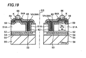
- Fig. 19 is a cross-sectional view of the semiconductor device separated into individual dice by dicing a silicon wafer along a dicing line after process steps to be described later.
- DS in Fig. 19 denotes a center of the dicing line.
- the same symbols are used in Fig. 19 to denote the same components as in the first embodiment shown in Fig. 14, and detailed explanations on them are omitted.
- the second embodiment is different from the first embodiment in that the wiring layer 64A fills the via hole VH incompletely, while the wiring layer 64A fills the via hole VH completely according to the first embodiment.
- the wiring layer 64 covers the bottom and the sidewall of the via hole VH, there is a hollow space in the via hole VH because its thickness is smaller than the radius of the via hole VH. A part of the solder mask 65 fills this space.
- the semiconductor device according to this structure has higher resistance against mechanical stress caused in mounting it to a printed circuit board than the semiconductor device according to the first embodiment in which the wiring layer 64 fills the via hole VH completely.
- a manufacturing method of the semiconductor device according to the second embodiment will be described next.
- the manufacturing method is the same as that in the first embodiment in process steps from the first process step through the process step to form the photoresist layer 63 (process steps shown in Figs. 1-9).
- the wiring layer 64A is formed to fill the via hole VH incompletely by electrolytic plating of copper (Cu) followed by electroless plating of nickel (Ni) and gold (Au), after forming the photoresist layer 63, as shown in Fig. 15.
- filling the via hole VH incompletely with the wiring layer 64 is made possible by adjusting length of time to give plating.
- the seed layer 62 is removed from the region under the photoresist layer 63 by etching using the wiring layer 64 as a mask, as shown in Fig. 16. Then the wiring layer 64A is covered with the solder mask 65, as shown in Fig. 17.
- solder is printed on predetermined regions on the wiring layers 64A using screen printing, and the solder is reflowed by heat treatment to form the solder balls 66, as shown in Fig. 18.
- the silicon wafer 51 is separated into the plurality of silicon dice 51A by dicing along the dicing line center DS, as shown in Fig. 19.
- This invention is not limited to the first and the second embodiments in which the wiring layer 64 and 64A are formed to fill the via hole VH by electrolytic plating. Other methods may be used. A method filling the via hole VH with metal such as copper (Cu) by CVD or MOCVD (Metal Organic Chemical Vapor Deposition) may be used, for example.
- metal such as copper (Cu) by CVD or MOCVD (Metal Organic Chemical Vapor Deposition) may be used, for example.
- this invention is not limited to the above-mentioned embodiments in which the solder ball 66 is formed on the wiring layer 64 or 64A extending from the via hole VH.
- the solder ball 66 may be formed on the wiring layer 64 or 64A buried in the via hole VH.
- this invention is not limited to including the pad electrode 53 formed by extending a normal pad electrode used for wire bonding to the dicing line region DL as described in the embodiments.
- the normal pad electrode used for wire bonding not extended to the dicing line region DL may be used instead of the pad electrode 53. In this case, only a location to form the via hole VH is required to be adjusted to a location of the normal pad, leaving other manufacturing process steps unchanged.
- Disconnection and deterioration in step coverage of the wiring between the pad electrode on the semiconductor die and the conductive terminal on the back surface of the semiconductor die can be prevented with this invention, leading to a BGA type semiconductor device having higher reliability.
- the conductive terminal is formed on the convex portion of the semiconductor, the conductive terminal is formed at the location elevated above the back surface of the semiconductor die. That makes it easier to absorb stress caused in mounting the semiconductor device on the printed circuit board, enabling preventing damage to the conductive terminal.
Abstract
Description
- This invention relates to a BGA (Ball Grid Array) type semiconductor device which has a plurality of ball-shaped conductive terminals and its manufacturing method.
- A CSP (Chip Size Package) receives attention in recent years as a three-dimensional mounting technology as well as a new packaging technology. The CSP means a small package having about the same outside dimensions as those of a semiconductor die packaged in it.
- A BGA type semiconductor device has been known as a kind of CSP. A plurality of ball-shaped conductive terminals made of metal such as solder are arrayed in a grid pattern on one surface of a package of the BGA type semiconductor device and is electrically connected with the semiconductor die mounted on the other side of the package.
- When the BGA type semiconductor device is mounted on electronic equipment, the semiconductor die is electrically connected with an external circuit on a printed circuit board by compression bonding of the conductive terminals to wiring patterns on the printed circuit board.
- Such a BGA type semiconductor device has advantages in providing a large number of conductive terminals and in reducing size over other CSP type semiconductor devices sucn as an SOP (Small Outline Package) and a QFP (Quad Flat Package), which have lead pins protruding from their sides. The BGA type semiconductor device is used as an image sensor chip for a digital camera incorporated into a mobile telephone, for example.
- Figs. 20A and 20B show outline structure of a conventional BGA type semiconductor device. Fig. 20A is an oblique perspective figure of a top side of the BGA type semiconductor device. And Fig. 20B is an oblique perspective figure of a back side of the BGA type semiconductor device.
- A
semiconductor die 104 is sealed between afirst glass substrate 102 and asecond glass substrate 103 throughepoxy resin layers type semiconductor device 101. A plurality of ball-shapedconductive terminals 106 are arrayed in a grid pattern on a surface of thesecond glass substrate 103, that is, on a back surface of the BGAtype semiconductor device 101. Theconductive terminals 106 are connected to the semiconductor die 104 through a plurality ofsecond wirings 110. The plurality ofsecond wirings 110 are connected with aluminum wirings pulled out from inside of thesemiconductor die 104, making the ball-shaped terminals 106 electrically connected with the semiconductor die 104. - More detailed explanation on a cross-sectional structure of the BGA
type semiconductor device 101 is given hereafter referring to Fig. 21. Fig. 21 shows a cross-sectional view of the BGAtype semiconductor devices 101 divided along dicing lines into individual dice. - A
first wiring 107 is provided on aninsulation film 108 on a top surface of the semiconductor die 104. Thesemiconductor die 104 is bonded to thefirst glass substrate 102 with theresin layer 105a. A back surface of thesemiconductor die 104 is bonded to thesecond glass substrate 103 with theresin layer 105b. - One end of the
first wiring 107 is connected to thesecond wiring 110. Thesecond wiring 110 extends from the end of thefirst wiring 107 onto a surface of thesecond glass substrate 103. And the ball-shapedconductive terminal 106 is formed on thesecond wiring 110 extended onto thesecond glass substrate 103. - However, there is a possibility that the
first wiring 107 and thesecond wiring 110 are disconnected at a point of contact between them, since the area of the point of contact is very small in the BGAtype semiconductor device 101 described above. Also there is a problem in step coverage of thesecond wiring 110. - The object of this invention is directed to solve the problems addressed above.
- The solution according to the invention lies in the features of the independent claims and preferably in those of the dependent claims.
- The invention offers a semiconductor device having a pad electrode provided on a first surface of a semiconductor die, a convex portion of semiconductor on a second surface of the semiconductor die and a supporting substrate bonded to the first surface of the semiconductor die provided with the pad electrode. And a via hole is formed in the semiconductor die from the second surface of the semiconductor die to a surface of the pad electrode and a wiring layer electrically connected with the pad electrode through the via hole is formed to extend from the via hole onto the second surface of the semiconductor die and to cover the convex portion of the semiconductor. In addition, a conductive terminal electrically connected with the wiring layer is formed on a portion of the wiring layer covering the convex portion of the semiconductor.
- Disconnection and deterioration in step coverage of the wiring everywhere between the pad electrode on the semiconductor die and the conductive terminal can be prevented with this invention, leading to a BGA type semiconductor device of higher reliability. Since the conductive terminal is formed on the convex portion of the semiconductor, the conductive terminal is formed at a location elevated by a height of the convex portion above the second surface of the semiconductor die. That makes it easier to relax thermal stress caused in mounting the semiconductor device on the printed circuit board, preventing damage to the conductive terminal.
-
- Fig. 1 is a cross-sectional view showing a manufacturing method of a semiconductor device according to a first embodiment of this invention.
- Fig. 2 is a cross-sectional view showing the manufacturing method of the semiconductor device according to the first embodiment of this invention.
- Fig. 3 is a cross-sectional view showing the manufacturing method of the semiconductor device according to the first embodiment of this invention.
- Fig. 4 is a cross-sectional view showing the manufacturing method of the semiconductor device according to the first embodiment of this invention.
- Fig. 5 is a cross-sectional view showing the manufacturing method of the semiconductor device according to the first embodiment of this invention.
- Fig. 6 is a cross-sectional view showing the manufacturing method of the semiconductor device according to the first embodiment of this invention.
- Fig. 7 is a cross-sectional view showing the manufacturing method of the semiconductor device according to the first embodiment of this invention.
- Fig. 8 is a cross-sectional view showing the manufacturing method of the semiconductor device according to the first embodiment of this invention.
- Fig. 9 is a cross-sectional view showing the manufacturing method of the semiconductor device according to the first embodiment of this invention.
- Fig. 10 is a cross-sectional view showing the manufacturing method of the semiconductor device according to the first embodiment of this invention.
- Fig. 11 is a cross-sectional view showing the manufacturing method of the semiconductor device according to the first embodiment of this invention.
- Fig. 12 is a cross-sectional view showing the manufacturing method of the semiconductor device according to the first embodiment of this invention.
- Fig. 13 is a cross-sectional view showing the manufacturing method of the semiconductor device according to the first embodiment of this invention.
- Fig. 14 is a cross-sectional view showing the semiconductor device and its manufacturing method according to the first embodiment of this invention.
- Fig. 15 is a cross-sectional view showing a manufacturing method of a semiconductor device according to a second embodiment of this invention.
- Fig. 16 is a cross-sectional view showing the manufacturing method of the semiconductor device according to the second embodiment of this invention.
- Fig. 17 is a cross-sectional view showing the manufacturing method of the semiconductor device according to the second embodiment of this invention.
- Fig. 18 is a cross-sectional view showing the manufacturing method of the semiconductor device according to the second embodiment of this invention.
- Fig. 19 is a cross-sectional view showing the semiconductor device and its manufacturing method according to the second embodiment of this invention.
- Figs. 20A and 20B are oblique perspective figures showing a semiconductor device according to a conventional art.
- Fig. 21 is a cross-sectional view showing the semiconductor device according to the conventional art.
-
- Next, a first embodiment of this invention will be described in detail, referring to figures hereinafter.
- First, a structure of the semiconductor device will be described. Fig. 14 is a cross-sectional view of the semiconductor device separated into individual dice by dicing a silicon wafer along a dicing line after process steps to be described later. DS in Fig. 14 denotes a center of the dicing line.
- A
pad electrode 53 is formed on a surface which is a first surface of asilicon die 51A through aninterlayer insulation film 52. The silicon die 51A is a CCD (Charge Couples Device) image sensor chip, for example. Thepad electrode 53 is formed by extending a normal pad electrode used for wire bonding to the dicing line region and is also called an extended pad electrode. - The
pad electrode 53 is covered with apassivation film 54 made of a silicon nitride film, for example. Aglass substrate 56 is bonded through aresin layer 55 made of an epoxy resin, for example, to a surface of the silicon die 51A, on which thepad electrode 53 is formed. Theglass substrate 56 is used as a supporting substrate to bolster the silicon die 51A. When the silicon die 51A is the CCD image sensor chip, using a transparent substrate such as theglass substrate 56 or a semitransparent substrate is required because light from outside needs to be received by the CCDs on the surface of the silicon die 51A. An opaque substrate may be used when the silicon die 51A is not a light-receiving or a light-emitting chip. - A via hole VH is formed in the silicon die 51A from a second surface which is a back surface of the silicon die 51A and to reach the
pad electrode 53. Asidewall insulation film 61A is formed on a sidewall of the via hole VH. Thesidewall insulation film 61A isolates the silicon die 51A from awiring layer 64 which will be described below. - A
convex portion 58 of silicon is formed on the back surface of the silicon die 51A in a region adjacent the via hole VH. Theconvex portion 58 of silicon is formed by etching a silicon substrate selectively, and height h of the convex portion is about 35 µm from the back surface of the silicon die 51A. The higher the height h is, the more effective to relax thermal stress when mounting the semiconductor device on a printed circuit board. A width W1 of theconvex portion 58 at its bottom is about 400 µm, and is determined according to a diameter of a solder ball. A width W2 of theconvex portion 58 at its top is about 340 µm. A thickness of the silicon die 51A is about 135 µm. - The back surface of the silicon die 51A and the
convex portion 58 of silicon are covered with afirst insulation film 59. Thefirst insulation film 59 isolates the silicon die 51A from thewiring layer 64. - The
wiring layer 64 connected to thepad electrode 53 electrically through the via hole VH is formed to extend from the via hole VH onto the back surface of the silicon die 51A. Thewiring layer 64 is also called a re-distribution layer, and has a structure of a layer of barrier metal such as Ni/Au stacked on a layer of copper (Cu), for example. Aseed layer 62 is provided under thewiring layer 64. Theseed layer 62 is a metal layer serving as a plating electrode in forming thewiring layer 64 by electrolytic plating. - When a metal having a high diffusivity into silicon such as copper is used for wiring, forming a barrier layer (TiN layer or TiW layer, for example) under the
seed layer 62 is preferred in order to prevent device characteristics from deteriorating by diffusion of copper. Thewiring layer 64 extends over the back surface of the silicon die 51A to cover theconvex portion 58 of silicon. - And the
wiring layer 64 is covered with asolder mask 65 which makes a protection film. An opening K is formed in thesolder mask 65 above theconvex portion 58 of silicon. Asolder ball 66 which makes the conductive terminal is mounted through the opening K in thesolder mask 65. Thesolder ball 66 is hereby electrically connected with thewiring layer 64. A BGA structure is obtained by forming a plurality ofsuch solder balls 66. - Wiring between the
pad electrodes 53 on the silicon die 51A and thesolder balls 66 formed on its back surface is formed as described above. Since the wiring is made through the via hole VH, disconnection occurs hardly and step coverage is excellent. In addition, mechanical strength of the wiring is high. Furthermore, since thesolder ball 66 is disposed on theconvex portion 58 of silicon, the location of the solder ball is higher by the height of the convex portion than the back surface of the silicon die 51A. Because of that, thesolder ball 66 and the silicon die 51A are better protected from potential damage caused by stress due to difference in coefficients of thermal expansion between the printed circuit board and thesolder ball 66, when the semiconductor device is mounted on the printed circuit board. - Next, a manufacturing method of the semiconductor device will be described hereinafter. It is assumed that a semiconductor integrated circuit (a CCD image sensor, for example, not shown) is formed on a surface of a
silicon wafer 51. Fig. 1 shows a cross-section of neighboring dice around a border along which the dice are to be separated in a subsequent dicing process. - A pair of
pad electrodes 53 is formed on a surface of thesilicon wafer 51 through theinterlayer insulation film 52 such as BPSG (Boro-Phospho Silicate Glass). The pair ofpad electrodes 53 is formed of a layer of metal such as aluminum, aluminum alloy or copper, and is about 1 µm thick. The pair ofpad electrodes 53 extends into a dicing line region DL with their extended ends being close to the center line DS of the dicing line. - The
passivation film 54 made of a silicon nitride film, for example, is formed to cover the pair ofpad electrodes 53 and aresin layer 55 made of an epoxy resin, for example, is applied to thepassivation film 54. Then theglass substrate 56 is bonded to the surface of thesilicon wafer 51 through theresin layer 55. Theglass substrate 56 works as a substrate to protect and bolster thesilicon wafer 51. After theglass substrate 56 is bonded, thickness of thesilicon wafer 51 is reduced to about 170 µm by back surface etching or so-called back-grinding when needed. - A photoresist is applied to the entire back surface of the
silicon wafer 51 after the back-grinding. Aphotoresist layer 57 is formed selectively by exposure and development of the photoresist. - The
convex portions 58 of silicon are formed by etching the back surface of thesilicon wafer 51 using thephotoresist layer 57 as a mask, as shown in Fig. 2. The etching can be either wet etching using a spin etcher or dry etching. The height h of theconvex portion 58 of silicon is about 35 µm and can be varied arbitrarily by adjusting an amount of the etching. - After removing the
photoresist layer 57 using a photoresist stripping solution, the back surface of thesilicon wafer 51 is wet-etched by about 5µm using the spin etcher or the like, as shown in Fig. 3. Corners at top edges of theconvex portions 58 of silicon are rounded with this, resulting in improvement of step coverage of thefirst insulation film 59. - Next, the
first insulation film 59 is formed on the entire back surface of thesilicon wafer 51, as shown in Fig. 4. Thefirst insulation film 59 is made by plasma CVD (Chemical Vapor Deposition), for example, and a PE-SiO2 film and a PE-SiN film are suitable for it. - Next, a
photoresist layer 60 is formed selectively on thefirst insulation film 59 and the via holes VH penetrating thesilicon wafer 51 are formed by etching thefirst insulation film 59 and thesilicon wafer 51 using thephotoresist layer 60 as a mask, as shown in Fig. 5. Theinterlayer insulation film 52 is exposed at the bottom of each of the via holes VH. Thepad electrode 53 is adjacent theinterlayer insulation film 52. Width of the via hole is about 40 µm and its length is about 200 µm. - The via holes VH may be formed by etching using a laser beam or by dry etching. The via holes VH are preferably formed to have tapered cross-sectional shape by controlling the laser beam in order to improve coverage of the
seed layer 62. - Next, a
second insulation film 61 is formed on the entire back surface of thesilicon wafer 51 in which the via holes VH are formed, as shown in Fig. 6. Thesecond insulation film 61 is made by plasma CVD, for example, and a PE-SiO2 film and a PE-SiN film are suitable for it. Thesecond insulation film 61 is formed on the bottom and the sidewall of the via holes VH and on thefirst insulation film 59. - Anisotropic dry etching without using a mask of a photoresist layer leaves the
second insulation film 61 only on the sidewalls of the via holes VH, which makes thesidewall insulation films 61A, as shown in Fig. 7. Thesecond insulation film 61 and theinterlayer insulation film 52 at the bottom of the via holes VH are etched off in this etching process to expose thepad electrodes 53. - As an alternative method to expose the
pad electrodes 53, thesecond insulation film 61 may be formed after removing theinterlayer insulation film 52 by anisotropic etching and then thesecond insulation film 61 at the bottom of the via holes VH may be removed by another anisotropic etching to expose thepad electrodes 53. Purpose is to secure good step coverage of thesidewall insulation film 61A. - Next, a process to form the
wiring layer 64 is described. Theseed layer 62 made of copper (Cu) is formed on the entire surface by electroless plating or by CVD after forming the barrier layer (TiN layer, for example) by sputtering or by CVD, as shown in Fig. 8. Theseed layer 62 serves as a plating electrode for growth of plating film during electrolytic plating. Thickness of about 100 nm is enough for it. Theseed layer 62 can be formed by sputtering when the via holes VH are formed in the tapered down shape. The barrier layer is formed to prevent copper from diffusing into silicon as mentioned before and its thickness is several tens of nanometers. - A
photoresist layer 63 is formed on a region where the plating is not to be made (Refer to Fig. 9.), prior to electrolytic plating of copper (Cu). The region is a region except for regions to form thewiring layer 64 and the solder balls. - Then the
wiring layer 64 is formed to fill the via holes VH completely by electrolytic plating of copper (Cu) followed by electroless plating of nickel (Ni) and gold (Au), as shown in Fig. 10. Ni and Au mentioned abovemake barrier metal 64a and may be formed by sputtering. Thewiring layer 64 fills the via holes VH and extends over the back surface of the silicon wafer to cover theconvex portions 58 of silicon. Thewiring layer 64 is electrically connected with thepad electrodes 53 through theseed layer 62. - Although this method is good to reduce the process steps, it has a demerit of not being able to optimize both the thickness of plated
wiring layer 64 and the thickness of the plated layer in the via holes VH, since the two thicknesses can not be controlled independently. Thus while thewiring layer 64 in the via holes VH (also referred to as a pillar-shaped conductive path) is formed by electrolytic plating, rest of thewiring layer 64 may be formed by Al sputtering or by another electrolytic plating. - Then the
photoresist layer 63 is removed, as shown in Fig. 11. Theseed layer 62 is removed from a region under thephotoresist layer 63 by etching using thewiring layer 64 as a mask. Although thewiring layer 64 is also etched in the process, it causes no problem since thewiring layer 64 is thicker than theseed layer 62. - Next, the
wiring layer 64 is covered with thesolder mask 65, as shown in Fig. 12. Thesolder mask 65 is removed from regions above theconvex portions 58 of silicon to provide the openings K. - And solder is printed on predetermined regions on the
wiring layer 64 using screen printing, and the solder is reflowed by heat treatment to form thesolder balls 66, as shown in Fig. 13. Note that desired number of the wiring layers 64 can be formed in desired regions on the back surface of thesilicon wafer 51 and that number and locations of thesolder balls 66 can be chosen at will. - The
silicon wafer 51 is separated into the plurality ofsilicon dice 51A by dicing along the dicing line center DS, as shown in Fig. 14. The laser beam may be used in the dicing process. When the laser beam is used in the dicing process, cut surface of theglass substrate 56 may be made tapered so that cracking of theglass substrate 56 is prevented. - Next, a second embodiment of this invention will be described in detail, referring to figures hereinafter. First, a structure of the semiconductor device will be described. Fig. 19 is a cross-sectional view of the semiconductor device separated into individual dice by dicing a silicon wafer along a dicing line after process steps to be described later. DS in Fig. 19 denotes a center of the dicing line. The same symbols are used in Fig. 19 to denote the same components as in the first embodiment shown in Fig. 14, and detailed explanations on them are omitted.
- The second embodiment is different from the first embodiment in that the
wiring layer 64A fills the via hole VH incompletely, while thewiring layer 64A fills the via hole VH completely according to the first embodiment. In other words, although thewiring layer 64 covers the bottom and the sidewall of the via hole VH, there is a hollow space in the via hole VH because its thickness is smaller than the radius of the via hole VH. A part of thesolder mask 65 fills this space. The semiconductor device according to this structure has higher resistance against mechanical stress caused in mounting it to a printed circuit board than the semiconductor device according to the first embodiment in which thewiring layer 64 fills the via hole VH completely. - A manufacturing method of the semiconductor device according to the second embodiment will be described next. The manufacturing method is the same as that in the first embodiment in process steps from the first process step through the process step to form the photoresist layer 63 (process steps shown in Figs. 1-9).
- Then, the
wiring layer 64A is formed to fill the via hole VH incompletely by electrolytic plating of copper (Cu) followed by electroless plating of nickel (Ni) and gold (Au), after forming thephotoresist layer 63, as shown in Fig. 15. In this process step, filling the via hole VH incompletely with thewiring layer 64 is made possible by adjusting length of time to give plating. - The rest of the process is the same as in the first embodiment. After the
photoresist layer 63 is removed, theseed layer 62 is removed from the region under thephotoresist layer 63 by etching using thewiring layer 64 as a mask, as shown in Fig. 16. Then thewiring layer 64A is covered with thesolder mask 65, as shown in Fig. 17. - And solder is printed on predetermined regions on the wiring layers 64A using screen printing, and the solder is reflowed by heat treatment to form the
solder balls 66, as shown in Fig. 18. - The
silicon wafer 51 is separated into the plurality ofsilicon dice 51A by dicing along the dicing line center DS, as shown in Fig. 19. - This invention is not limited to the first and the second embodiments in which the
wiring layer - Also, this invention is not limited to the above-mentioned embodiments in which the
solder ball 66 is formed on thewiring layer solder ball 66 may be formed on thewiring layer - Furthermore, this invention is not limited to including the
pad electrode 53 formed by extending a normal pad electrode used for wire bonding to the dicing line region DL as described in the embodiments. The normal pad electrode used for wire bonding not extended to the dicing line region DL may be used instead of thepad electrode 53. In this case, only a location to form the via hole VH is required to be adjusted to a location of the normal pad, leaving other manufacturing process steps unchanged. - Disconnection and deterioration in step coverage of the wiring between the pad electrode on the semiconductor die and the conductive terminal on the back surface of the semiconductor die can be prevented with this invention, leading to a BGA type semiconductor device having higher reliability.
- Since the conductive terminal is formed on the convex portion of the semiconductor, the conductive terminal is formed at the location elevated above the back surface of the semiconductor die. That makes it easier to absorb stress caused in mounting the semiconductor device on the printed circuit board, enabling preventing damage to the conductive terminal.
Claims (14)
- A semiconductor device comprising:a semiconductor die (51A) comprising a first surface, a second surface and a convex portion (58) formed on the second surface, a via hole (VH) being formed in the semiconductor die (51A) between the first and second surfaces;a pad electrode (53) disposed on the first surface of the semiconductor die (51A) and covering one end of the via hole (VH);a supporting substrate (56) bonded to the first surface of the semiconductor die (51A);a wiring layer (64) formed on the second surface of the semiconductor die (51A) and electrically connected with the pad electrode (53) through the via hole (VH), the wiring layer (64) at least partially filling the via hole (VH), extending through another end of the via hole and covering the convex portion (58); anda conductive terminal (66) formed on a portion of the wiring layer (64) covering the convex portion (58) and electrically connected with the wiring layer (64).
- The semiconductor device of claim 1, further comprising an insulation layer (61A) formed on a sidewall of the via hole (VH) to electrically isolate the wiring layer (64) from the semiconductor die (51A).
- The semiconductor device of claim 1 or 2, wherein the via hole (VH) is completely filled with the wiring layer (64).
- The semiconductor device of claim 1 or 2, wherein the via hole (VH) is not completely filled with the wiring layer (64).
- A method of manufacturing a semiconductor device comprising:forming a pad electrode (53) on a first surface of a semiconductor substrate (51);bonding a supporting substrate (56) to the first surface of the semiconductor substrate (51);forming a layer of photoresist (57) on a predetermined region of a second surface of the semiconductor substrate (51);etching the semiconductor substrate (51) using the layer of photoresist (57) as a mask to form a convex portion (58);forming a via hole (VH) in the semiconductor substrate (51) from the second surface of the semiconductor substrate (51) to expose a surface of the pad electrode (53);forming a wiring layer (64) electrically connected with the pad electrode (53) on the second surface of the semiconductor substrate (51) so that the wiring layer (64) at least partially fills the via hole (VH), extends from a top end of the via hole (VH) and covers the convex portion (58);forming a conductive terminal (66) on the wiring layer (64); anddividing the semiconductor substrate into a plurality of semiconductor dice.
- The method of claim 5, wherein the wiring layer (64) is formed by electrolytic plating or by sputtering.
- The method of claim 5 or 6, further comprising forming an insulation layer (61) on a sidewall of the via hole (VH) to electrically isolate the wiring layer (64) from the semiconductor substrate (51).
- The method of claim 5 or 6, wherein the wiring layer (64) is formed to fill the via hole (VH) completely.
- The method of claim 5 or 6, wherein the wiring layer (64) is formed to fill the via hole (VH) only partially.
- The method according to any of claims 5 to 9, further comprising rounding a corner of the convex portion (58) of semiconductor (51).
- A method of manufacturing a semiconductor device comprising:forming a pad electrode (53) on a first surface of a semiconductor substrate (51);bonding a supporting substrate (56) to the first surface of the semiconductor substrate (51);forming a layer of photoresist (57) on a predetermined region of a second surface of the semiconductor substrate (51);etching the semiconductor substrate (51) using the layer of photoresist (57) as a mask to form a convex portion (58);forming an insulation film (59) on the second surface of the semiconductor substrate (51) after removing the layer of photoresist (57);forming a via hole (VH) in the semiconductor substrate (51) from the insulation film (59) to expose a surface of the pad electrode (53);forming another insulation film (61) on a sidewall of the via hole;forming a seed layer (62) on the another insulation film (61);forming a wiring layer (64) electrically connected with the pad electrode (53) on the second surface of the semiconductor substrate (51) by electrolytic plating so that the wiring layer (64) at least partially fills the via hole (VH), extends from a top end of the via hole (VH) and covers the convex portion (58);forming a conductive terminal (66) on the wiring layer (64); anddividing the semiconductor substrate (51) into a plurality of semiconductor dice (51A).
- The method of claim 11, wherein the wiring layer (64) is formed to fill the via hole (VH) completely.
- The method of claim 11, wherein the wiring layer (64) is formed to fill the via hole (VH) only partially.
- The method according to any of claims 11 to 13, further comprising rounding a corner of the convex portion (58) of semiconductor.
Applications Claiming Priority (2)
| Application Number | Priority Date | Filing Date | Title |
|---|---|---|---|
| JP2003147146 | 2003-05-26 | ||
| JP2003147146A JP2004349593A (en) | 2003-05-26 | 2003-05-26 | Semiconductor device and method for manufacturing the same |
Publications (3)
| Publication Number | Publication Date |
|---|---|
| EP1482552A2 true EP1482552A2 (en) | 2004-12-01 |
| EP1482552A3 EP1482552A3 (en) | 2007-03-21 |
| EP1482552B1 EP1482552B1 (en) | 2010-08-04 |
Family
ID=33128189
Family Applications (1)
| Application Number | Title | Priority Date | Filing Date |
|---|---|---|---|
| EP04012464A Expired - Fee Related EP1482552B1 (en) | 2003-05-26 | 2004-05-26 | Semiconductor device |
Country Status (7)
| Country | Link |
|---|---|
| US (1) | US7579671B2 (en) |
| EP (1) | EP1482552B1 (en) |
| JP (1) | JP2004349593A (en) |
| KR (1) | KR100608184B1 (en) |
| CN (2) | CN100370607C (en) |
| DE (1) | DE602004028430D1 (en) |
| TW (1) | TWI233189B (en) |
Cited By (4)
| Publication number | Priority date | Publication date | Assignee | Title |
|---|---|---|---|---|
| WO2005055310A2 (en) * | 2003-12-03 | 2005-06-16 | Schott Ag | Process for packaging components, and packaged components |
| EP1641039A1 (en) * | 2004-09-24 | 2006-03-29 | Sanyo Electric Co., Ltd. | Semiconductor device manufacturing method |
| US8101496B2 (en) | 2003-06-09 | 2012-01-24 | Semiconductor Components Industries, Llc | Method of manufacturing ball grid array type semiconductor device |
| CN102473639A (en) * | 2010-03-09 | 2012-05-23 | 松下电器产业株式会社 | Process for production of semiconductor device, and semiconductor device |
Families Citing this family (23)
| Publication number | Priority date | Publication date | Assignee | Title |
|---|---|---|---|---|
| JP4708009B2 (en) * | 2004-12-14 | 2011-06-22 | 株式会社フジクラ | Wiring board manufacturing method |
| JP2007036060A (en) * | 2005-07-28 | 2007-02-08 | Sanyo Electric Co Ltd | Semiconductor device and manufacturing method thereof |
| JP4745007B2 (en) * | 2005-09-29 | 2011-08-10 | 三洋電機株式会社 | Semiconductor device and manufacturing method thereof |
| JP2007311771A (en) * | 2006-04-21 | 2007-11-29 | Sanyo Electric Co Ltd | Semiconductor device and method of manufacturing the same |
| KR100828027B1 (en) * | 2006-06-28 | 2008-05-08 | 삼성전자주식회사 | Stack type wafer level package and method of manufacturing the same, and wafer level stack package and method of manufacturing the same |
| WO2008023824A1 (en) * | 2006-08-25 | 2008-02-28 | Sanyo Electric Co., Ltd. | Semiconductor device and method for manufacturing the same |
| US8653612B2 (en) * | 2006-08-25 | 2014-02-18 | Sanyo Semiconductor Co., Ltd. | Semiconductor device |
| US8212331B1 (en) * | 2006-10-02 | 2012-07-03 | Newport Fab, Llc | Method for fabricating a backside through-wafer via in a processed wafer and related structure |
| KR100843240B1 (en) | 2007-03-23 | 2008-07-03 | 삼성전자주식회사 | Semiconductor device for wafer level stack and forming method of through electrode thereof |
| US7923645B1 (en) * | 2007-06-20 | 2011-04-12 | Amkor Technology, Inc. | Metal etch stop fabrication method and structure |
| JP5281831B2 (en) * | 2008-06-30 | 2013-09-04 | 株式会社荏原製作所 | Method for forming conductive material structure |
| US8784636B2 (en) | 2007-12-04 | 2014-07-22 | Ebara Corporation | Plating apparatus and plating method |
| US9293678B2 (en) | 2010-07-15 | 2016-03-22 | Micron Technology, Inc. | Solid-state light emitters having substrates with thermal and electrical conductivity enhancements and method of manufacture |
| US8816505B2 (en) | 2011-07-29 | 2014-08-26 | Tessera, Inc. | Low stress vias |
| US20130313710A1 (en) * | 2012-05-22 | 2013-11-28 | Micron Technology, Inc. | Semiconductor Constructions and Methods of Forming Semiconductor Constructions |
| US20140151095A1 (en) * | 2012-12-05 | 2014-06-05 | Samsung Electro-Mechanics Co., Ltd. | Printed circuit board and method for manufacturing the same |
| JP6359444B2 (en) * | 2014-12-25 | 2018-07-18 | 東京エレクトロン株式会社 | Wiring layer forming method, wiring layer forming system, and storage medium |
| WO2017130381A1 (en) * | 2016-01-29 | 2017-08-03 | 三菱電機株式会社 | Semiconductor device |
| TWI623049B (en) * | 2016-11-04 | 2018-05-01 | 英屬開曼群島商鳳凰先驅股份有限公司 | Package substrate and its fabrication method |
| JP6963396B2 (en) * | 2017-02-28 | 2021-11-10 | キヤノン株式会社 | Manufacturing method of electronic parts |
| KR102420586B1 (en) | 2017-07-24 | 2022-07-13 | 삼성전자주식회사 | Semiconductor devices, semiconductor packages, and method of manufacturing the Semiconductor devices |
| JP2019160893A (en) * | 2018-03-09 | 2019-09-19 | ソニーセミコンダクタソリューションズ株式会社 | Solid state imaging element, semiconductor device, electronic device, and manufacturing method |
| JP7279306B2 (en) * | 2018-06-28 | 2023-05-23 | 凸版印刷株式会社 | wiring board |
Family Cites Families (29)
| Publication number | Priority date | Publication date | Assignee | Title |
|---|---|---|---|---|
| US3761782A (en) * | 1971-05-19 | 1973-09-25 | Signetics Corp | Semiconductor structure, assembly and method |
| JPH0321859A (en) | 1989-06-20 | 1991-01-30 | Nippondenso Co Ltd | Oxygen sensor |
| US5229647A (en) * | 1991-03-27 | 1993-07-20 | Micron Technology, Inc. | High density data storage using stacked wafers |
| DE4312976A1 (en) * | 1993-04-21 | 1994-10-27 | Bosch Gmbh Robert | Contacting of electrically conductive layers of a layer system |
| US6124179A (en) * | 1996-09-05 | 2000-09-26 | Adamic, Jr.; Fred W. | Inverted dielectric isolation process |
| US5684331A (en) * | 1995-06-07 | 1997-11-04 | Lg Semicon Co., Ltd. | Multilayered interconnection of semiconductor device |
| US5851911A (en) * | 1996-03-07 | 1998-12-22 | Micron Technology, Inc. | Mask repattern process |
| US5946555A (en) * | 1996-11-04 | 1999-08-31 | Packard Hughes Interconnect Company | Wafer level decal for minimal packaging of chips |
| US5904496A (en) | 1997-01-24 | 1999-05-18 | Chipscale, Inc. | Wafer fabrication of inside-wrapped contacts for electronic devices |
| IL120514A (en) * | 1997-03-25 | 2000-08-31 | P C B Ltd | Electronic interconnect structure and method for manufacturing it |
| JPH10303327A (en) * | 1997-04-23 | 1998-11-13 | Yamaichi Electron Co Ltd | Contact point conversion structure of semiconductor chip, and method for manufacturing semiconductor chip comprising contact point conversion structure |
| US6586829B1 (en) * | 1997-12-18 | 2003-07-01 | Si Diamond Technology, Inc. | Ball grid array package |
| IL123207A0 (en) | 1998-02-06 | 1998-09-24 | Shellcase Ltd | Integrated circuit device |
| US6114221A (en) * | 1998-03-16 | 2000-09-05 | International Business Machines Corporation | Method and apparatus for interconnecting multiple circuit chips |
| US6303988B1 (en) * | 1998-04-22 | 2001-10-16 | Packard Hughes Interconnect Company | Wafer scale burn-in socket |
| KR100266698B1 (en) * | 1998-06-12 | 2000-09-15 | 김영환 | Semiconductor chip package and fabrication method thereof |
| US6271059B1 (en) | 1999-01-04 | 2001-08-07 | International Business Machines Corporation | Chip interconnection structure using stub terminals |
| US6263566B1 (en) * | 1999-05-03 | 2001-07-24 | Micron Technology, Inc. | Flexible semiconductor interconnect fabricated by backslide thinning |
| JP3450238B2 (en) * | 1999-11-04 | 2003-09-22 | Necエレクトロニクス株式会社 | Semiconductor device and manufacturing method thereof |
| JP3879816B2 (en) * | 2000-06-02 | 2007-02-14 | セイコーエプソン株式会社 | SEMICONDUCTOR DEVICE AND ITS MANUFACTURING METHOD, LAMINATED SEMICONDUCTOR DEVICE, CIRCUIT BOARD AND ELECTRONIC DEVICE |
| JP2002094082A (en) * | 2000-07-11 | 2002-03-29 | Seiko Epson Corp | Optical element and its manufacturing method and electronic equipment |
| US6350633B1 (en) * | 2000-08-22 | 2002-02-26 | Charles W. C. Lin | Semiconductor chip assembly with simultaneously electroplated contact terminal and connection joint |
| US6693358B2 (en) * | 2000-10-23 | 2004-02-17 | Matsushita Electric Industrial Co., Ltd. | Semiconductor chip, wiring board and manufacturing process thereof as well as semiconductor device |
| US6444489B1 (en) | 2000-12-15 | 2002-09-03 | Charles W. C. Lin | Semiconductor chip assembly with bumped molded substrate |
| US6433427B1 (en) * | 2001-01-16 | 2002-08-13 | Industrial Technology Research Institute | Wafer level package incorporating dual stress buffer layers for I/O redistribution and method for fabrication |
| JP2002373957A (en) | 2001-06-14 | 2002-12-26 | Shinko Electric Ind Co Ltd | Semiconductor device and its manufacturing method |
| JP4053257B2 (en) | 2001-06-14 | 2008-02-27 | 新光電気工業株式会社 | Manufacturing method of semiconductor device |
| JP4000507B2 (en) | 2001-10-04 | 2007-10-31 | ソニー株式会社 | Method for manufacturing solid-state imaging device |
| US6908784B1 (en) * | 2002-03-06 | 2005-06-21 | Micron Technology, Inc. | Method for fabricating encapsulated semiconductor components |
-
2003
- 2003-05-26 JP JP2003147146A patent/JP2004349593A/en active Pending
-
2004
- 2004-05-17 TW TW093113810A patent/TWI233189B/en not_active IP Right Cessation
- 2004-05-24 US US10/851,638 patent/US7579671B2/en active Active
- 2004-05-25 KR KR1020040037141A patent/KR100608184B1/en not_active IP Right Cessation
- 2004-05-26 EP EP04012464A patent/EP1482552B1/en not_active Expired - Fee Related
- 2004-05-26 CN CNB2004100476315A patent/CN100370607C/en not_active Expired - Fee Related
- 2004-05-26 DE DE602004028430T patent/DE602004028430D1/en active Active
- 2004-05-26 CN CNA2007101619625A patent/CN101174600A/en active Pending
Non-Patent Citations (1)
| Title |
|---|
| None |
Cited By (10)
| Publication number | Priority date | Publication date | Assignee | Title |
|---|---|---|---|---|
| US8101496B2 (en) | 2003-06-09 | 2012-01-24 | Semiconductor Components Industries, Llc | Method of manufacturing ball grid array type semiconductor device |
| WO2005055310A2 (en) * | 2003-12-03 | 2005-06-16 | Schott Ag | Process for packaging components, and packaged components |
| WO2005055310A3 (en) * | 2003-12-03 | 2005-11-03 | Schott Ag | Process for packaging components, and packaged components |
| US7700397B2 (en) | 2003-12-03 | 2010-04-20 | Schott Ag | Process for packaging components, and packaged components |
| US8309384B2 (en) | 2003-12-03 | 2012-11-13 | Wafer-Level Packaging Portfolio Llc | Process for packaging components, and packaged components |
| EP1641039A1 (en) * | 2004-09-24 | 2006-03-29 | Sanyo Electric Co., Ltd. | Semiconductor device manufacturing method |
| US7413931B2 (en) | 2004-09-24 | 2008-08-19 | Sanyo Electric Co., Ltd. | Semiconductor device manufacturing method |
| CN102473639A (en) * | 2010-03-09 | 2012-05-23 | 松下电器产业株式会社 | Process for production of semiconductor device, and semiconductor device |
| EP2546868A1 (en) * | 2010-03-09 | 2013-01-16 | Panasonic Corporation | Process for production of semiconductor device, and semiconductor device |
| EP2546868A4 (en) * | 2010-03-09 | 2014-04-09 | Panasonic Corp | Process for production of semiconductor device, and semiconductor device |
Also Published As
| Publication number | Publication date |
|---|---|
| TWI233189B (en) | 2005-05-21 |
| EP1482552A3 (en) | 2007-03-21 |
| CN1574324A (en) | 2005-02-02 |
| TW200428608A (en) | 2004-12-16 |
| DE602004028430D1 (en) | 2010-09-16 |
| CN101174600A (en) | 2008-05-07 |
| KR100608184B1 (en) | 2006-08-08 |
| JP2004349593A (en) | 2004-12-09 |
| EP1482552B1 (en) | 2010-08-04 |
| CN100370607C (en) | 2008-02-20 |
| US7579671B2 (en) | 2009-08-25 |
| US20050006783A1 (en) | 2005-01-13 |
| KR20040101924A (en) | 2004-12-03 |
Similar Documents
| Publication | Publication Date | Title |
|---|---|---|
| US7579671B2 (en) | Semiconductor device and manufacturing method thereof | |
| US8101496B2 (en) | Method of manufacturing ball grid array type semiconductor device | |
| EP1564807B1 (en) | Semiconductor device and manufacturing method of the same | |
| US7622810B2 (en) | Semiconductor device and manufacturing method thereof | |
| US9165898B2 (en) | Method of manufacturing semiconductor device with through hole | |
| EP1482553A2 (en) | Semiconductor device and manufacturing method thereof | |
| US7416963B2 (en) | Manufacturing method of semiconductor device | |
| US7339273B2 (en) | Semiconductor device with a via hole having a diameter at the surface larger than a width of a pad electrode | |
| US7759247B2 (en) | Manufacturing method of semiconductor device with a barrier layer and a metal layer | |
| US7663213B2 (en) | Wafer level chip size packaged chip device with a double-layer lead structure and method of fabricating the same | |
| EP1686622A2 (en) | Semiconductor device and manufacturing method of the same | |
| US7557017B2 (en) | Method of manufacturing semiconductor device with two-step etching of layer | |
| JP3970211B2 (en) | Semiconductor device and manufacturing method thereof | |
| JP3970210B2 (en) | Manufacturing method of semiconductor device | |
| JP4282514B2 (en) | Manufacturing method of semiconductor device | |
| JP4845986B2 (en) | Semiconductor device | |
| JP4769926B2 (en) | Semiconductor device and manufacturing method thereof |
Legal Events
| Date | Code | Title | Description |
|---|---|---|---|
| PUAI | Public reference made under article 153(3) epc to a published international application that has entered the european phase |
Free format text: ORIGINAL CODE: 0009012 |
|
| AK | Designated contracting states |
Kind code of ref document: A2 Designated state(s): AT BE BG CH CY CZ DE DK EE ES FI FR GB GR HU IE IT LI LU MC NL PL PT RO SE SI SK TR |
|
| AX | Request for extension of the european patent |
Extension state: AL HR LT LV MK |
|
| PUAL | Search report despatched |
Free format text: ORIGINAL CODE: 0009013 |
|
| AK | Designated contracting states |
Kind code of ref document: A3 Designated state(s): AT BE BG CH CY CZ DE DK EE ES FI FR GB GR HU IE IT LI LU MC NL PL PT RO SE SI SK TR |
|
| AX | Request for extension of the european patent |
Extension state: AL HR LT LV MK |
|
| 17P | Request for examination filed |
Effective date: 20070921 |
|
| AKX | Designation fees paid |
Designated state(s): DE FI FR GB |
|
| 17Q | First examination report despatched |
Effective date: 20071120 |
|
| RIC1 | Information provided on ipc code assigned before grant |
Ipc: H01L 23/31 20060101ALI20091126BHEP Ipc: H01L 23/48 20060101AFI20091126BHEP Ipc: H01L 23/485 20060101ALI20091126BHEP |
|
| GRAP | Despatch of communication of intention to grant a patent |
Free format text: ORIGINAL CODE: EPIDOSNIGR1 |
|
| RIC1 | Information provided on ipc code assigned before grant |
Ipc: H01L 23/485 20060101ALI20100203BHEP Ipc: H01L 23/31 20060101ALI20100203BHEP Ipc: H01L 23/48 20060101AFI20100203BHEP |
|
| RTI1 | Title (correction) |
Free format text: SEMICONDUCTOR DEVICE |
|
| GRAS | Grant fee paid |
Free format text: ORIGINAL CODE: EPIDOSNIGR3 |
|
| GRAA | (expected) grant |
Free format text: ORIGINAL CODE: 0009210 |
|
| AK | Designated contracting states |
Kind code of ref document: B1 Designated state(s): DE FI FR GB |
|
| REG | Reference to a national code |
Ref country code: GB Ref legal event code: FG4D |
|
| REF | Corresponds to: |
Ref document number: 602004028430 Country of ref document: DE Date of ref document: 20100916 Kind code of ref document: P |
|
| PG25 | Lapsed in a contracting state [announced via postgrant information from national office to epo] |
Ref country code: FI Free format text: LAPSE BECAUSE OF FAILURE TO SUBMIT A TRANSLATION OF THE DESCRIPTION OR TO PAY THE FEE WITHIN THE PRESCRIBED TIME-LIMIT Effective date: 20100804 |
|
| PLBE | No opposition filed within time limit |
Free format text: ORIGINAL CODE: 0009261 |
|
| STAA | Information on the status of an ep patent application or granted ep patent |
Free format text: STATUS: NO OPPOSITION FILED WITHIN TIME LIMIT |
|
| 26N | No opposition filed |
Effective date: 20110506 |
|
| REG | Reference to a national code |
Ref country code: DE Ref legal event code: R097 Ref document number: 602004028430 Country of ref document: DE Effective date: 20110506 |
|
| PGFP | Annual fee paid to national office [announced via postgrant information from national office to epo] |
Ref country code: GB Payment date: 20130425 Year of fee payment: 10 Ref country code: DE Payment date: 20130531 Year of fee payment: 10 |
|
| PGFP | Annual fee paid to national office [announced via postgrant information from national office to epo] |
Ref country code: FR Payment date: 20130531 Year of fee payment: 10 |
|
| REG | Reference to a national code |
Ref country code: DE Ref legal event code: R119 Ref document number: 602004028430 Country of ref document: DE |
|
| GBPC | Gb: european patent ceased through non-payment of renewal fee |
Effective date: 20140526 |
|
| REG | Reference to a national code |
Ref country code: FR Ref legal event code: ST Effective date: 20150130 |
|
| REG | Reference to a national code |
Ref country code: DE Ref legal event code: R119 Ref document number: 602004028430 Country of ref document: DE Effective date: 20141202 |
|
| PG25 | Lapsed in a contracting state [announced via postgrant information from national office to epo] |
Ref country code: DE Free format text: LAPSE BECAUSE OF NON-PAYMENT OF DUE FEES Effective date: 20141202 |
|
| PG25 | Lapsed in a contracting state [announced via postgrant information from national office to epo] |
Ref country code: FR Free format text: LAPSE BECAUSE OF NON-PAYMENT OF DUE FEES Effective date: 20140602 Ref country code: GB Free format text: LAPSE BECAUSE OF NON-PAYMENT OF DUE FEES Effective date: 20140526 |