EP1481849A1 - Foldable warning triangle - Google Patents
Foldable warning triangle Download PDFInfo
- Publication number
- EP1481849A1 EP1481849A1 EP20030398004 EP03398004A EP1481849A1 EP 1481849 A1 EP1481849 A1 EP 1481849A1 EP 20030398004 EP20030398004 EP 20030398004 EP 03398004 A EP03398004 A EP 03398004A EP 1481849 A1 EP1481849 A1 EP 1481849A1
- Authority
- EP
- European Patent Office
- Prior art keywords
- warning triangle
- reflector arrangement
- wire
- wire bracket
- base panel
- Prior art date
- Legal status (The legal status is an assumption and is not a legal conclusion. Google has not performed a legal analysis and makes no representation as to the accuracy of the status listed.)
- Granted
Links
Images


Classifications
-
- B—PERFORMING OPERATIONS; TRANSPORTING
- B60—VEHICLES IN GENERAL
- B60Q—ARRANGEMENT OF SIGNALLING OR LIGHTING DEVICES, THE MOUNTING OR SUPPORTING THEREOF OR CIRCUITS THEREFOR, FOR VEHICLES IN GENERAL
- B60Q7/00—Arrangement or adaptation of portable emergency signal devices on vehicles
- B60Q7/005—Devices without lamps
Definitions
- Warning triangles generally comprise a reflector arrangement of three panels and a stand for supporting the reflector arrangement on the ground.
- a warning triangle for a motor car has to provide certain stability with respect to its use. More specifically, the triangle must stay still in a wind tunnel at a wind velocity of 60 km/h. Further, its maximum displacement in vertical direction has to be less than 50 mm under a load of 200 g. There are also minimum requirements for the size of the unfolded triangle.
- the stand usually comprises a rigid horizontal base plate made of metal and carrying the reflector arrangement.
- the reflector arrangement is held in slots of the base plate which function as joints so that the reflector arrangement may pivot to a certain degree about a substantially horizontal axis in order to compensate gusts of wind.
- the stand is provided with four legs spreading out in two pairs from end portions of the rigid base plate below the comers of the reflector arrangement. In an unfolded state, the legs and base plate form a H-shaped structure with the legs extending on either side of the triangle and being inclined towards the ground.
- warning triangle Even though the prior art warning triangle provides good stability, it is relatively heavy in weight. As in many countries a warning triangle is to be kept in every passenger vehicle in order to have it on hand in the event of a breakdown of the vehicle, it is desired that the warning triangle be of a lightweight construction. It is also desired that the triangle can be folded very compactly, and requires little storage space.
- the present invention aims at providing a lightweight warning triangle, which has sufficient stability and requires little space in its folded state.
- the invention provides a foldable warning triangle, comprising a reflector arrangement having two side panels pivotally joined to end portions of a base panel, respectively, a stand formed by vertically elastic means extending under the reflector arrangement and fixed to the reflector arrangement and two pairs of legs pivotally supported on the vertically elastic means, wherein the stand is rigidly fixed to the reflector arrangement and provides a spring effect in vertical direction by the vertically elastic means.
- the inventive warning triangle does not require a heavy, rigid base plate. Sufficient stability and flexibility is obtained by the stand, which provides a spring effect. Accordingly, the warning triangle according to the invention has low weight and at the same time enough flexibility to successfully perform a wind test and a load test under the above-mentioned conditions. In fact, the inventive triangle is able to stand still for wind velocities up to 70 km/h.
- the vertically elastic means may include helicoidal springs, a wire bracket or any other elements, which provide additional elasticity in vertical direction.
- a preferred embodiment of the invention uses a wire bracket which is fixed to the reflector arrangement at the joints of the base panel and supports the two pairs of legs, which results in a warning triangle, that can be manufactured in a very cost efficient manner.
- the wire bracket comprises two separate wire elements. These wire elements are connected with each other by means of a coupling element while the coupling element is supported on the base panel of the reflector arrangement.
- the coupling element may comprise two openings at its lower side for receiving upwardly bent portions of the two wire elements, respectively.
- the coupling element or spacer is provided with recesses for retaining the folded legs spaced apart from each other.
- the coupling element or spacer provides a second function in addition to providing a flexible connection between the wire bracket and the reflector arrangement, namely preventing the folded legs from rattling during transport.
- the wire bracket is formed with two upwardly bent end portions, which are secured between two panels, respectively, at the joints of these panels. This enables the wire bracket to be easily mounted on the base panel of the reflector arrangement.
- the end portions of the wire bracket are secured without play between the panels so that the reflector arrangement is stably held on the wire bracket.
- the upwardly bent end portions also provide a spring effect allowing the triangle to bend backwards and forwards under a wind load.
- the whole structure of the triangle has a continuous flexibility without play from ground to top.
- the base panel of the reflector arrangement is provided with receptacles in the vicinity of its joints for clamping L-shaped arms of the end portions of the wire bracket.
- the wire bracket can be assembled on the base panel without the use of special tools. It is also possible, to assemble both elements in an automated procedure. Because of their L-shape the end portions are easily pressed in intersecting channels, which are preferably located around a pin or protrusion of the corresponding joint on the base panel.
- each leg may be fixed on the wire bracket through two leg holders.
- Each leg holder is spaced apart from the base panel of the reflector arrangement to allow for vertical displacement.
- each leg holder pivotally supports two legs. By the leg holders, it is possible to connect the legs to the relatively thin wire of the wire bracket.
- the leg holders improve the assembly of the stand because they offer the option of mounting two legs on the holder first and subsequently fixing the unit on the wire bracket.
- the leg holders are arranged below the joints of the base panel while the coupling element is arranged in the middle between the leg holders. This adds to stability and flexibility of the stand.
- the diameter of the wire of the wire bracket elements are dimensioned so as to provide the required spring properties in vertical direction and sufficient mechanical resistance between the reflector arrangement and the stand, in particular in horizontal direction. Accordingly, the diameter of the wire of the wire bracket may be smaller than the diameter of the legs. This also keeps the weight of the warning triangle low.
- the leg holders can be secured on substantially U-shaped bends of the wire bracket, which open towards the ground. Accordingly, the leg holders and legs can be inserted from the bottom and will be stably held on the thin wire bracket.
- wire bracket and leg holders may be configured in such manner that in the event of a vertical load exerted on top of the unfolded triangle the leg holders swivel inwardly.
- the figures 1 to 6 show a preferred embodiment of a warning triangle 1 which can be folded so as to form a compact package for storing it in a small storage space, e.g. in a motor vehicle.
- the folded triangle 1 is kept in a lengthy box in order to protect it during transport.
- Figures 5 and 6 show the folded triangle 1 whereas the unfolded state is shown in figure 1.
- the warning triangle 1 is constituted by a reflector arrangement 2 and a stand 3 for supporting the reflector arrangement 2 on the ground.
- the reflector arrangement 2 comprises two side panels 4 and 5 and a base panel 6 connecting the side panels 4 and 5. Joints 7 and 8 provided at the end portions 9 and 10 of the base panel 6 allow the side panels 4 and 5 to swivel in order to unfold the reflector arrangement 2. In an unfolded state the three panels 4, 5 and 6 form an equal-sided triangle whereas in the folded state the panels 4, 5 and 6 are piled side by side, as can be seen in Figure 5, with the base panel 6 being arranged between the side panels 4 and 5.
- Each panel 4, 5 or 6 is provided with one reflector element 11. However, it is also possible to provide several reflector elements 11 on one or each of the panels 4, 5 and 6.
- the reflector elements 11 may be either attached to the panels 4, 5 or 6, for example by vibration welding, or be formed integrally with them.
- one of the side panels 4 has a projection 12, which releasably engages with an opening 13 formed at the end portion of the other side panel 5.
- the projection 12 is arranged on the rear side of panel 4, which in the folded state of the triangle 1 is arranged behind the base panel 6.
- each joint 7 and 8 between the panels 4, 5 and 6 includes rivets 7a and 8a inserted from the rear but it is also possible to pivotally connect the panels 4, 5 and 6 in a different manner.
- each joint 7 and 8 further includes a protrusion 14 to maintain a small axial distance between the respective panels 4 and 6 or 5 and 6, the function of which will be explained hereinafter.
- the protrusions 14 are integrally formed with the respective end portions 9 and 10 of the base panel 6.
- the reflector arrangement 2 comprises a reflecting sheet 15 which is be visible through the triangular opening formed between the panels 4, 5 and 6 in the unfolded state.
- the reflecting sheet 15 has a central triangular opening 16 and is fixed on the rear of the panels 4, 5 and 6 by means of the afore-mentioned rivets and further at the projection 12.
- the projection 12 may be formed as a pin or rivet that is secured on the side panel 4 and at the same time secures the top of the reflecting sheet 15.
- the stand 3 of the warning triangle 1 comprises vertically elastic means formed by a wire bracket 17, and two pairs of legs 18 pivotally supported on the vertically elastic means, i.e. the wire bracket 17.
- the wire bracket 17 extends under the reflector arrangement 2 without extending beyond the length of the base panel 6 and is fixed to the reflector arrangement only at the joints 7 and 8 of the base panel 6, whereas the major part of the wire bracket 17 is spaced apart from the lower edge of the base panel 6.
- the wire bracket may also be supported in the middle of the base panel 6 by means of a spacer or coupling element 19.
- the present invention does not require a heavy base plate. To the contrary, it uses a relatively thin wire for a lightweight wire bracket 17, which provides a spring effect in a vertical direction and preferably also with respect to a forward and backward movement of the reflector arrangement 2, thus effecting an overall flexibility of the warning triangle 1.
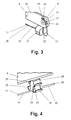
- the wire bracket 17 comprises a horizontal portion 20 and two upwardly bent end portions 21 which are secured between the base panel 6 and the side panels 4 or 5. As shown in figure 3, the upwardly bent end portions 21 curve inwardly to form an L-shaped end having two arms 22 and 23. These arms 22 and 23 radially abut the afore-mentioned protrusion 14, which is slightly thicker than the wire at the bent end portions 21. Additional projections 24 and 25 around the protrusion 14 define receptacles in the vicinity of the respective joints 7 and 8 for clamping the L-shaped arms 22 and 23 of the end portions 21 of the wire bracket 17. Accordingly, the wire bracket 17 is secured on the base panel 6 without play.
- the wire bracket 17 comprises two separate wire elements 26. These wire elements 26, which are identical in shape, are a connected at second end portions 27 thereof with each other by means of the coupling element 19. The second end portions 27 are bent upwardly and are inserted into openings 28 provided in the bottom side of the coupling element 19.
- the coupling element 19 is a spacer element only.
- the coupling element 19 is supported on the base panel 6, for example through a snap fit connection. Further, the coupling element 19 is provided with recesses 29 and 30 for retaining the folded legs 18 to keep them spaced apart from each other. The recesses 29 and 30 are arranged on either side of the coupling element 19. In the folded state of the warning triangle 1 the recesses 29 and 30 secure the legs 18 in their position in order to prevent rattling during transport.
- the legs 18 are coupled to the wire bracket 17 through leg holders 31.
- Each leg holder 31 is adapted to pivotally support two legs 18.
- the two leg holders 31 are fixed on the wire bracket 17 with each leg holder being spaced apart vertically from the base panel 6 of the reflector arrangement 2.
- the leg holders 31 are arranged below the joints 7 and 8 of the base panel 6.
- the leg holders 31 are formed as blocks of plastics material having two channels for receiving and guiding two legs 18.
- a groove 32 on top of the block and on its sides is adapted to engage with the wire of the wire bracket 17 in order to secure the leg holders 31 on the wire bracket 17.
- the wire bracket 17 or its wire elements 26 are formed with substantially U-shaped bends 33 which open towards the ground so that the leg holders 31 can be inserted and fixed from the bottom side.
- the wire bracket 17 and leg holders 31 are configured in such manner that in the event of a vertical load exerted on top of the unfolded triangle 1 the leg holders 31 swivel slightly towards the centre of the wire bracket 17, i.e. the left leg holder 31 in figure 1 swivels clockwise whereas the right leg holder 31 swivels anticlockwise.
- the leg holders 31 and the coupling element 19 are preferably made of light material such as plastics material.
- the wire bracket 17 and the legs 18 are preferably made of steel. In this connection, it should be noted that the diameter of the wire of the wire bracket 17 is smaller than the diameter of the legs 18.
- the warning triangle 1 as described above is light in weight but provides sufficient stability with regard to wind loads and vertical loads. Moreover, it requires little space in its folded state. It is easy to manufacture and can be assembled very efficiently.
- the invention is not limited the warning triangle of the preferred embodiment but includes all warning triangles as defined in the claims.
Abstract
Description
- The invention relates to a foldable warning triangle. Warning triangles generally comprise a reflector arrangement of three panels and a stand for supporting the reflector arrangement on the ground.
- According to regulation no. 27.03 of the European Union, a warning triangle for a motor car has to provide certain stability with respect to its use. More specifically, the triangle must stay still in a wind tunnel at a wind velocity of 60 km/h. Further, its maximum displacement in vertical direction has to be less than 50 mm under a load of 200 g. There are also minimum requirements for the size of the unfolded triangle.
- Conventional warning triangles meet these criteria by using a heavy stand to give weight to the triangle. The stand usually comprises a rigid horizontal base plate made of metal and carrying the reflector arrangement. The reflector arrangement is held in slots of the base plate which function as joints so that the reflector arrangement may pivot to a certain degree about a substantially horizontal axis in order to compensate gusts of wind. Further, the stand is provided with four legs spreading out in two pairs from end portions of the rigid base plate below the comers of the reflector arrangement. In an unfolded state, the legs and base plate form a H-shaped structure with the legs extending on either side of the triangle and being inclined towards the ground. Thus, the technical concept of this prior art construction resides in the idea of providing a heavy and rigid stand, having a centre of gravity that is sufficiently low with regard to the spreading legs to avoid any significant displacement of the triangle under the above-mentioned conditions. A warning triangle of this type is disclosed in EP 0 819 577 A2.
- Even though the prior art warning triangle provides good stability, it is relatively heavy in weight. As in many countries a warning triangle is to be kept in every passenger vehicle in order to have it on hand in the event of a breakdown of the vehicle, it is desired that the warning triangle be of a lightweight construction. It is also desired that the triangle can be folded very compactly, and requires little storage space.
- Accordingly, the present invention aims at providing a lightweight warning triangle, which has sufficient stability and requires little space in its folded state.
- The invention provides a foldable warning triangle, comprising a reflector arrangement having two side panels pivotally joined to end portions of a base panel, respectively, a stand formed by vertically elastic means extending under the reflector arrangement and fixed to the reflector arrangement and two pairs of legs pivotally supported on the vertically elastic means, wherein the stand is rigidly fixed to the reflector arrangement and provides a spring effect in vertical direction by the vertically elastic means.
- In contrast to the prior art warning triangle, the inventive warning triangle does not require a heavy, rigid base plate. Sufficient stability and flexibility is obtained by the stand, which provides a spring effect. Accordingly, the warning triangle according to the invention has low weight and at the same time enough flexibility to successfully perform a wind test and a load test under the above-mentioned conditions. In fact, the inventive triangle is able to stand still for wind velocities up to 70 km/h.
- The vertically elastic means may include helicoidal springs, a wire bracket or any other elements, which provide additional elasticity in vertical direction.
- A preferred embodiment of the invention uses a wire bracket which is fixed to the reflector arrangement at the joints of the base panel and supports the two pairs of legs, which results in a warning triangle, that can be manufactured in a very cost efficient manner.
- According to a further preferred embodiment of the invention the wire bracket comprises two separate wire elements. These wire elements are connected with each other by means of a coupling element while the coupling element is supported on the base panel of the reflector arrangement.
- The coupling element may comprise two openings at its lower side for receiving upwardly bent portions of the two wire elements, respectively.
- According to another preferred embodiment, the coupling element or spacer is provided with recesses for retaining the folded legs spaced apart from each other. Thus, the coupling element or spacer provides a second function in addition to providing a flexible connection between the wire bracket and the reflector arrangement, namely preventing the folded legs from rattling during transport.
- In order to efficiently connect the stand to the reflector arrangement the wire bracket is formed with two upwardly bent end portions, which are secured between two panels, respectively, at the joints of these panels. This enables the wire bracket to be easily mounted on the base panel of the reflector arrangement.
- Preferably, the end portions of the wire bracket are secured without play between the panels so that the reflector arrangement is stably held on the wire bracket. Of course, the upwardly bent end portions also provide a spring effect allowing the triangle to bend backwards and forwards under a wind load. Thus, the whole structure of the triangle has a continuous flexibility without play from ground to top.
- According to another preferred embodiment of the invention the base panel of the reflector arrangement is provided with receptacles in the vicinity of its joints for clamping L-shaped arms of the end portions of the wire bracket. By this, the wire bracket can be assembled on the base panel without the use of special tools. It is also possible, to assemble both elements in an automated procedure. Because of their L-shape the end portions are easily pressed in intersecting channels, which are preferably located around a pin or protrusion of the corresponding joint on the base panel.
- Further, the legs may be fixed on the wire bracket through two leg holders. Each leg holder is spaced apart from the base panel of the reflector arrangement to allow for vertical displacement. Moreover, each leg holder pivotally supports two legs. By the leg holders, it is possible to connect the legs to the relatively thin wire of the wire bracket. The leg holders improve the assembly of the stand because they offer the option of mounting two legs on the holder first and subsequently fixing the unit on the wire bracket.
- Preferably, the leg holders are arranged below the joints of the base panel while the coupling element is arranged in the middle between the leg holders. This adds to stability and flexibility of the stand.
- The diameter of the wire of the wire bracket elements are dimensioned so as to provide the required spring properties in vertical direction and sufficient mechanical resistance between the reflector arrangement and the stand, in particular in horizontal direction. Accordingly, the diameter of the wire of the wire bracket may be smaller than the diameter of the legs. This also keeps the weight of the warning triangle low.
- The leg holders can be secured on substantially U-shaped bends of the wire bracket, which open towards the ground. Accordingly, the leg holders and legs can be inserted from the bottom and will be stably held on the thin wire bracket.
- Further, the wire bracket and leg holders may be configured in such manner that in the event of a vertical load exerted on top of the unfolded triangle the leg holders swivel inwardly.
- Subsequently, the invention will be described in detail by means of a preferred embodiment as shown in the appended drawings.
- Figure 1
- shows a side view of a warning triangle according to the invention in its unfolded state,
- Figure 2
- shows a perspective view of a wire element of a wire bracket of the warning triangle shown in figure 1,
- Figure 3
- shows a perspective view of an end portion of the wire bracket fixed to a base panel of a reflector arrangement of the warning triangle as shown in figure 1,
- Figure 4
- shows a perspective view of a coupling element for a connecting to wire elements as shown in figure 1,
- Figure 5
- shows a partial side view of the warning triangle in its folded state, and
- Figure 6
- shows a front end in view of the folded warning triangle.
- The figures 1 to 6 show a preferred embodiment of a
warning triangle 1 which can be folded so as to form a compact package for storing it in a small storage space, e.g. in a motor vehicle. Preferably, the foldedtriangle 1 is kept in a lengthy box in order to protect it during transport. Figures 5 and 6 show the foldedtriangle 1 whereas the unfolded state is shown in figure 1. - The
warning triangle 1 is constituted by areflector arrangement 2 and astand 3 for supporting thereflector arrangement 2 on the ground. - The
reflector arrangement 2 comprises twoside panels base panel 6 connecting theside panels Joints end portions base panel 6 allow theside panels reflector arrangement 2. In an unfolded state the threepanels panels base panel 6 being arranged between theside panels panel reflector element 11. However, it is also possible to provideseveral reflector elements 11 on one or each of thepanels reflector elements 11 may be either attached to thepanels - In order to connect the free ends of the
side panels side panels 4 has aprojection 12, which releasably engages with anopening 13 formed at the end portion of theother side panel 5. Theprojection 12 is arranged on the rear side ofpanel 4, which in the folded state of thetriangle 1 is arranged behind thebase panel 6. When theside panels projection 12 is inserted from the front side (reflecting side) into theopening 13 of thesecond side panel 5 and subsequently held by a snap connection. - The
joints panels rivets panels protrusion 14 to maintain a small axial distance between therespective panels protrusions 14 are integrally formed with therespective end portions base panel 6. - Further, the
reflector arrangement 2 comprises a reflectingsheet 15 which is be visible through the triangular opening formed between thepanels sheet 15 has a centraltriangular opening 16 and is fixed on the rear of thepanels projection 12. Preferably, theprojection 12 may be formed as a pin or rivet that is secured on theside panel 4 and at the same time secures the top of the reflectingsheet 15. - The
stand 3 of thewarning triangle 1 comprises vertically elastic means formed by awire bracket 17, and two pairs oflegs 18 pivotally supported on the vertically elastic means, i.e. thewire bracket 17. As shown in figure 1, thewire bracket 17 extends under thereflector arrangement 2 without extending beyond the length of thebase panel 6 and is fixed to the reflector arrangement only at thejoints base panel 6, whereas the major part of thewire bracket 17 is spaced apart from the lower edge of thebase panel 6. However, the wire bracket may also be supported in the middle of thebase panel 6 by means of a spacer orcoupling element 19. In contrast to conventional warning triangles the present invention does not require a heavy base plate. To the contrary, it uses a relatively thin wire for alightweight wire bracket 17, which provides a spring effect in a vertical direction and preferably also with respect to a forward and backward movement of thereflector arrangement 2, thus effecting an overall flexibility of thewarning triangle 1. - The
wire bracket 17 comprises ahorizontal portion 20 and two upwardlybent end portions 21 which are secured between thebase panel 6 and theside panels bent end portions 21 curve inwardly to form an L-shaped end having twoarms arms protrusion 14, which is slightly thicker than the wire at thebent end portions 21.Additional projections protrusion 14 define receptacles in the vicinity of therespective joints arms end portions 21 of thewire bracket 17. Accordingly, thewire bracket 17 is secured on thebase panel 6 without play. - In the embodiment shown, the
wire bracket 17 comprises twoseparate wire elements 26. Thesewire elements 26, which are identical in shape, are a connected atsecond end portions 27 thereof with each other by means of thecoupling element 19. Thesecond end portions 27 are bent upwardly and are inserted intoopenings 28 provided in the bottom side of thecoupling element 19. In would be possible, to use a one-piece wire bracket 17 wherein thecoupling element 19 is a spacer element only. However, research and tests showed superiority for the structure having twowire elements 26 with regard to stability in the wind test and load test. - As already mentioned, the
coupling element 19 is supported on thebase panel 6, for example through a snap fit connection. Further, thecoupling element 19 is provided withrecesses legs 18 to keep them spaced apart from each other. Therecesses coupling element 19. In the folded state of thewarning triangle 1 therecesses legs 18 in their position in order to prevent rattling during transport. - The
legs 18 are coupled to thewire bracket 17 throughleg holders 31. Eachleg holder 31 is adapted to pivotally support twolegs 18. The twoleg holders 31 are fixed on thewire bracket 17 with each leg holder being spaced apart vertically from thebase panel 6 of thereflector arrangement 2. As shown in figure 1, theleg holders 31 are arranged below thejoints base panel 6. Preferably, theleg holders 31 are formed as blocks of plastics material having two channels for receiving and guiding twolegs 18. Agroove 32 on top of the block and on its sides is adapted to engage with the wire of thewire bracket 17 in order to secure theleg holders 31 on thewire bracket 17. As shown in figure 2, thewire bracket 17 or itswire elements 26 are formed with substantiallyU-shaped bends 33 which open towards the ground so that theleg holders 31 can be inserted and fixed from the bottom side. Thewire bracket 17 andleg holders 31 are configured in such manner that in the event of a vertical load exerted on top of the unfoldedtriangle 1 theleg holders 31 swivel slightly towards the centre of thewire bracket 17, i.e. theleft leg holder 31 in figure 1 swivels clockwise whereas theright leg holder 31 swivels anticlockwise. - In order to provide a lightweight construction the
leg holders 31 and thecoupling element 19 are preferably made of light material such as plastics material. However, in order to provide the spring effect thewire bracket 17 and thelegs 18 are preferably made of steel. In this connection, it should be noted that the diameter of the wire of thewire bracket 17 is smaller than the diameter of thelegs 18. - The
warning triangle 1 as described above is light in weight but provides sufficient stability with regard to wind loads and vertical loads. Moreover, it requires little space in its folded state. It is easy to manufacture and can be assembled very efficiently. - However, the invention is not limited the warning triangle of the preferred embodiment but includes all warning triangles as defined in the claims.
-
- 1
- Warning triangle
- 2
- Reflector arrangement
- 3
- Stand
- 4
- Side panel
- 5
- Side panel
- 6
- Base panel
- 7
- Joint
- 7a
- Rivet
- 8
- Joint
- 8a
- Rivet
- 9
- End portion
- 10
- End portion
- 11
- Reflector element
- 12
- Projection
- 13
- Opening
- 14
- Protrusion
- 15
- Reflecting sheet
- 16
- Central triangular opening
- 17
- Wire bracket
- 18
- Leg
- 19
- Coupling element
- 20
- Horizontal portion
- 21
- Upwardly bent end portion
- 22
- Arm
- 23
- Arm
- 24
- Additional projection
- 25
- Additional projection
- 26
- Wire element
- 27
- Second end portion
- 28
- Opening
- 29
- Recess
- 30
- Recess
- 31
- Leg holder
- 32
- Groove
- 33
- U-shaped bend
Claims (10)
- Foldable warning triangle, comprising:wherein the stand (3) is rigidly fixed to the reflector arrangement (2) and provides a spring effect at the top of the triangle in vertical direction by said vertically elastic means.a reflector arrangement (2) having two side panels (4, 5) pivotally joined to end portions (9, 10) of a base panel (6), respectively, anda stand (3) formed by vertically elastic means extending under the reflector arrangement (2) and fixed to the reflector arrangement (2) and two pairs of legs (18) pivotally supported on the vertically elastic means,
- Foldable warning triangle according to claim 1, characterized in that the vertically elastic means include helicoidal springs.
- Foldable warning triangle according to claim 1, characterized in that the vertically elastic means include a wire bracket (17) preferably extending under the reflector arrangement (2), fixed to the reflector arrangement (2) at the joints (7, 8) of the base panel (6), and supporting the two pairs of legs ( 18).
- Foldable warning triangle according to claim 3, characterised in that the wire bracket (17) comprises two separate wire elements (26), the wire (26) elements are a connected with each other by means of a coupling element (19), and the coupling element (19) is supported on the base panel (6) of the reflector arrangement (2).
- Foldable warning triangle according to claim 3 or 4, characterised in that the wire bracket (17) comprises two upwardly bent end portions (21) which are secured between two panels (4, 6; 5, 6), respectively, at the joints (7, 8) of these panels (4, 5, 6).
- Foldable warning triangle according to one of claims 3 to 5, characterised in that the base panel (6) is provided with receptacles in the vicinity of its joints (7, 8) for clamping L-shaped arms (22, 23) of the end portions (21) of the wire bracket (17).
- Foldable warning triangle according to one of claims 1 to 6, characterised in that two leg holders (31) are fixed on the vertically elastic means with each leg holder (31) being spaced apart from the base panel (6) of the reflector arrangement (2) and pivotally supporting two legs (18).
- Foldable warning triangle according to one of claims 4 to 7, characterised in that the leg holders (31) are arranged below the joints (7, 8) of the base panel (6) while the coupling element ( 19) is arranged in the middle between the leg holders (31).
- Foldable warning triangle according to one of claims 3 to 8 characterised in that the diameter of the wire of the wire bracket (17) is smaller than the diameter of the legs (18).
- Foldable warning triangle according to one of claims 3 to 9, characterised in that the leg holders (31) are secured on substantially U-shaped bends (33) of the wire bracket (17) which open towards the ground.
Priority Applications (5)
| Application Number | Priority Date | Filing Date | Title |
|---|---|---|---|
| DE60311773T DE60311773D1 (en) | 2003-05-30 | 2003-05-30 | Retractable warning triangle |
| AT03398004T ATE353791T1 (en) | 2003-05-30 | 2003-05-30 | FOLDABLE WARNING TRIANGLE |
| EP03398004A EP1481849B1 (en) | 2003-05-30 | 2003-05-30 | Foldable warning triangle |
| ES03398004T ES2281615T3 (en) | 2003-05-30 | 2003-05-30 | FOLDING EMERGENCY TRIANGLE. |
| PT03398004T PT1481849E (en) | 2003-05-30 | 2003-05-30 | Foldable warning triangle |
Applications Claiming Priority (1)
| Application Number | Priority Date | Filing Date | Title |
|---|---|---|---|
| EP03398004A EP1481849B1 (en) | 2003-05-30 | 2003-05-30 | Foldable warning triangle |
Publications (2)
| Publication Number | Publication Date |
|---|---|
| EP1481849A1 true EP1481849A1 (en) | 2004-12-01 |
| EP1481849B1 EP1481849B1 (en) | 2007-02-14 |
Family
ID=33104226
Family Applications (1)
| Application Number | Title | Priority Date | Filing Date |
|---|---|---|---|
| EP03398004A Expired - Lifetime EP1481849B1 (en) | 2003-05-30 | 2003-05-30 | Foldable warning triangle |
Country Status (5)
| Country | Link |
|---|---|
| EP (1) | EP1481849B1 (en) |
| AT (1) | ATE353791T1 (en) |
| DE (1) | DE60311773D1 (en) |
| ES (1) | ES2281615T3 (en) |
| PT (1) | PT1481849E (en) |
Cited By (3)
| Publication number | Priority date | Publication date | Assignee | Title |
|---|---|---|---|---|
| EP1894778A1 (en) * | 2006-09-04 | 2008-03-05 | Suwary Sa | Warning triangle |
| EP2165885A1 (en) | 2008-09-17 | 2010-03-24 | Suwary Sa | Traffic warning triangle |
| CN107599964A (en) * | 2017-09-20 | 2018-01-19 | 岭南师范学院 | A kind of automobile automatic warning device |
Families Citing this family (1)
| Publication number | Priority date | Publication date | Assignee | Title |
|---|---|---|---|---|
| DE102008010608B4 (en) * | 2008-02-22 | 2010-01-14 | Leina-Werke Gmbh | Collapsible warning triangle |
Citations (6)
| Publication number | Priority date | Publication date | Assignee | Title |
|---|---|---|---|---|
| US4288052A (en) * | 1979-05-24 | 1981-09-08 | Scott George B | Base for free standing merchandiser |
| EP0078520A1 (en) * | 1981-11-03 | 1983-05-11 | BURGER SÖHNE GmbH + Co. | Removable warning triangle for vehicles |
| DE20001925U1 (en) * | 2000-02-04 | 2000-07-13 | Burger Soehne | Warning triangle |
| DE20001230U1 (en) * | 2000-01-25 | 2000-07-27 | Funke Karlheinz | Wind gust warning triangle |
| DE20017169U1 (en) * | 2000-10-06 | 2001-02-22 | Lutzenberger Helmut | Warning triangle - Stand device with drill openings - Rod in twist-clamp bolt, molded part or extra block, elastic |
| DE20201661U1 (en) * | 2002-02-04 | 2002-04-04 | Nagatrend Engineering Sdn Bhd | warning triangle |
-
2003
- 2003-05-30 AT AT03398004T patent/ATE353791T1/en not_active IP Right Cessation
- 2003-05-30 ES ES03398004T patent/ES2281615T3/en not_active Expired - Lifetime
- 2003-05-30 DE DE60311773T patent/DE60311773D1/en not_active Expired - Lifetime
- 2003-05-30 EP EP03398004A patent/EP1481849B1/en not_active Expired - Lifetime
- 2003-05-30 PT PT03398004T patent/PT1481849E/en unknown
Patent Citations (6)
| Publication number | Priority date | Publication date | Assignee | Title |
|---|---|---|---|---|
| US4288052A (en) * | 1979-05-24 | 1981-09-08 | Scott George B | Base for free standing merchandiser |
| EP0078520A1 (en) * | 1981-11-03 | 1983-05-11 | BURGER SÖHNE GmbH + Co. | Removable warning triangle for vehicles |
| DE20001230U1 (en) * | 2000-01-25 | 2000-07-27 | Funke Karlheinz | Wind gust warning triangle |
| DE20001925U1 (en) * | 2000-02-04 | 2000-07-13 | Burger Soehne | Warning triangle |
| DE20017169U1 (en) * | 2000-10-06 | 2001-02-22 | Lutzenberger Helmut | Warning triangle - Stand device with drill openings - Rod in twist-clamp bolt, molded part or extra block, elastic |
| DE20201661U1 (en) * | 2002-02-04 | 2002-04-04 | Nagatrend Engineering Sdn Bhd | warning triangle |
Cited By (5)
| Publication number | Priority date | Publication date | Assignee | Title |
|---|---|---|---|---|
| EP1894778A1 (en) * | 2006-09-04 | 2008-03-05 | Suwary Sa | Warning triangle |
| WO2008028921A1 (en) * | 2006-09-04 | 2008-03-13 | Suwary S.A. | Warning triangle |
| EP2165885A1 (en) | 2008-09-17 | 2010-03-24 | Suwary Sa | Traffic warning triangle |
| CN107599964A (en) * | 2017-09-20 | 2018-01-19 | 岭南师范学院 | A kind of automobile automatic warning device |
| CN107599964B (en) * | 2017-09-20 | 2023-11-14 | 岭南师范学院 | Automatic warning device for automobile |
Also Published As
| Publication number | Publication date |
|---|---|
| ES2281615T3 (en) | 2007-10-01 |
| PT1481849E (en) | 2007-06-06 |
| DE60311773D1 (en) | 2007-03-29 |
| ATE353791T1 (en) | 2007-03-15 |
| EP1481849B1 (en) | 2007-02-14 |
Similar Documents
| Publication | Publication Date | Title |
|---|---|---|
| US6076233A (en) | Grab rail and hook assembly for a vehicle | |
| US6648395B2 (en) | Vehicle rear seat | |
| US7080914B1 (en) | Vehicular mirror with adjustable pivot connection | |
| US6629726B2 (en) | Storage apparatus that attaches to a vehicle seat | |
| US7698775B2 (en) | Windshield wiper assembly having a body made of spring steel | |
| US5967054A (en) | Removable cargo shelf assembly for a vehicle | |
| US7309105B2 (en) | Lift wire lumbar | |
| US7726709B2 (en) | Vehicle bumper structure | |
| JP4533760B2 (en) | Car trunk floor board | |
| JP2001187588A (en) | Front end structure of vehicle | |
| JPH105076A (en) | Seat back for seat of vehicle | |
| CN102098945A (en) | Tension mechanism for a weight-responsive chair | |
| CN101827728A (en) | Rear view mirror | |
| US20120181315A1 (en) | In-vehicle fixture for driving assist device | |
| WO2012133679A1 (en) | Mechanism for raising vehicle seat, and vehicle seat | |
| EP1481849B1 (en) | Foldable warning triangle | |
| US6059238A (en) | Snap-in armrest | |
| KR20150056011A (en) | Automatic Spread Tripod | |
| US6398375B1 (en) | Vehicular mirror | |
| JPS63502019A (en) | Vehicle suspension system | |
| JPS5853547A (en) | Windshield wiper device | |
| US20190232739A1 (en) | Trailer Coupling | |
| JP6220776B2 (en) | Seat mounting structure | |
| US6951184B2 (en) | Crossing control arm assembly | |
| US7510286B2 (en) | Exterior rearview mirror for vehicles, preferably for motor vehicles |
Legal Events
| Date | Code | Title | Description |
|---|---|---|---|
| PUAI | Public reference made under article 153(3) epc to a published international application that has entered the european phase |
Free format text: ORIGINAL CODE: 0009012 |
|
| AK | Designated contracting states |
Kind code of ref document: A1 Designated state(s): AT BE BG CH CY CZ DE DK EE ES FI FR GB GR HU IE IT LI LU MC NL PT RO SE SI SK TR |
|
| AX | Request for extension of the european patent |
Extension state: AL LT LV MK |
|
| 17P | Request for examination filed |
Effective date: 20050531 |
|
| AKX | Designation fees paid |
Designated state(s): AT BE BG CH CY CZ DE DK EE ES FI FR GB GR HU IE IT LI LU MC NL PT RO SE SI SK TR |
|
| GRAP | Despatch of communication of intention to grant a patent |
Free format text: ORIGINAL CODE: EPIDOSNIGR1 |
|
| GRAS | Grant fee paid |
Free format text: ORIGINAL CODE: EPIDOSNIGR3 |
|
| GRAA | (expected) grant |
Free format text: ORIGINAL CODE: 0009210 |
|
| RIN1 | Information on inventor provided before grant (corrected) |
Inventor name: RODRIGUES LELLO, JOSE LUIS Inventor name: DE MAGALHAES CERQUEIRA, FERNANDO ANTONIO Inventor name: GALIZIA CARNEIRO BARRAL, JOSE MANUEL |
|
| AK | Designated contracting states |
Kind code of ref document: B1 Designated state(s): AT BE BG CH CY CZ DE DK EE ES FI FR GB GR HU IE IT LI LU MC NL PT RO SE SI SK TR |
|
| PG25 | Lapsed in a contracting state [announced via postgrant information from national office to epo] |
Ref country code: DK Free format text: LAPSE BECAUSE OF FAILURE TO SUBMIT A TRANSLATION OF THE DESCRIPTION OR TO PAY THE FEE WITHIN THE PRESCRIBED TIME-LIMIT Effective date: 20070214 Ref country code: CH Free format text: LAPSE BECAUSE OF FAILURE TO SUBMIT A TRANSLATION OF THE DESCRIPTION OR TO PAY THE FEE WITHIN THE PRESCRIBED TIME-LIMIT Effective date: 20070214 Ref country code: SI Free format text: LAPSE BECAUSE OF FAILURE TO SUBMIT A TRANSLATION OF THE DESCRIPTION OR TO PAY THE FEE WITHIN THE PRESCRIBED TIME-LIMIT Effective date: 20070214 Ref country code: NL Free format text: LAPSE BECAUSE OF FAILURE TO SUBMIT A TRANSLATION OF THE DESCRIPTION OR TO PAY THE FEE WITHIN THE PRESCRIBED TIME-LIMIT Effective date: 20070214 Ref country code: AT Free format text: LAPSE BECAUSE OF FAILURE TO SUBMIT A TRANSLATION OF THE DESCRIPTION OR TO PAY THE FEE WITHIN THE PRESCRIBED TIME-LIMIT Effective date: 20070214 Ref country code: LI Free format text: LAPSE BECAUSE OF FAILURE TO SUBMIT A TRANSLATION OF THE DESCRIPTION OR TO PAY THE FEE WITHIN THE PRESCRIBED TIME-LIMIT Effective date: 20070214 Ref country code: FI Free format text: LAPSE BECAUSE OF FAILURE TO SUBMIT A TRANSLATION OF THE DESCRIPTION OR TO PAY THE FEE WITHIN THE PRESCRIBED TIME-LIMIT Effective date: 20070214 Ref country code: BE Free format text: LAPSE BECAUSE OF FAILURE TO SUBMIT A TRANSLATION OF THE DESCRIPTION OR TO PAY THE FEE WITHIN THE PRESCRIBED TIME-LIMIT Effective date: 20070214 |
|
| REG | Reference to a national code |
Ref country code: GB Ref legal event code: FG4D |
|
| REG | Reference to a national code |
Ref country code: CH Ref legal event code: EP |
|
| REF | Corresponds to: |
Ref document number: 60311773 Country of ref document: DE Date of ref document: 20070329 Kind code of ref document: P |
|
| REG | Reference to a national code |
Ref country code: IE Ref legal event code: FG4D |
|
| PG25 | Lapsed in a contracting state [announced via postgrant information from national office to epo] |
Ref country code: SE Free format text: LAPSE BECAUSE OF FAILURE TO SUBMIT A TRANSLATION OF THE DESCRIPTION OR TO PAY THE FEE WITHIN THE PRESCRIBED TIME-LIMIT Effective date: 20070514 |
|
| PG25 | Lapsed in a contracting state [announced via postgrant information from national office to epo] |
Ref country code: BG Free format text: LAPSE BECAUSE OF EXPIRATION OF PROTECTION Effective date: 20070515 |
|
| REG | Reference to a national code |
Ref country code: PT Ref legal event code: SC4A Free format text: AVAILABILITY OF NATIONAL TRANSLATION Effective date: 20070509 |
|
| NLV1 | Nl: lapsed or annulled due to failure to fulfill the requirements of art. 29p and 29m of the patents act | ||
| ET | Fr: translation filed | ||
| REG | Reference to a national code |
Ref country code: CH Ref legal event code: PL |
|
| REG | Reference to a national code |
Ref country code: ES Ref legal event code: FG2A Ref document number: 2281615 Country of ref document: ES Kind code of ref document: T3 |
|
| PG25 | Lapsed in a contracting state [announced via postgrant information from national office to epo] |
Ref country code: SK Free format text: LAPSE BECAUSE OF FAILURE TO SUBMIT A TRANSLATION OF THE DESCRIPTION OR TO PAY THE FEE WITHIN THE PRESCRIBED TIME-LIMIT Effective date: 20070214 |
|
| PLBE | No opposition filed within time limit |
Free format text: ORIGINAL CODE: 0009261 |
|
| STAA | Information on the status of an ep patent application or granted ep patent |
Free format text: STATUS: NO OPPOSITION FILED WITHIN TIME LIMIT |
|
| PG25 | Lapsed in a contracting state [announced via postgrant information from national office to epo] |
Ref country code: CZ Free format text: LAPSE BECAUSE OF FAILURE TO SUBMIT A TRANSLATION OF THE DESCRIPTION OR TO PAY THE FEE WITHIN THE PRESCRIBED TIME-LIMIT Effective date: 20070214 Ref country code: RO Free format text: LAPSE BECAUSE OF FAILURE TO SUBMIT A TRANSLATION OF THE DESCRIPTION OR TO PAY THE FEE WITHIN THE PRESCRIBED TIME-LIMIT Effective date: 20070214 |
|
| 26N | No opposition filed |
Effective date: 20071115 |
|
| GBPC | Gb: european patent ceased through non-payment of renewal fee |
Effective date: 20070530 |
|
| PG25 | Lapsed in a contracting state [announced via postgrant information from national office to epo] |
Ref country code: MC Free format text: LAPSE BECAUSE OF NON-PAYMENT OF DUE FEES Effective date: 20070531 Ref country code: DE Free format text: LAPSE BECAUSE OF FAILURE TO SUBMIT A TRANSLATION OF THE DESCRIPTION OR TO PAY THE FEE WITHIN THE PRESCRIBED TIME-LIMIT Effective date: 20070515 |
|
| PG25 | Lapsed in a contracting state [announced via postgrant information from national office to epo] |
Ref country code: IT Free format text: LAPSE BECAUSE OF FAILURE TO SUBMIT A TRANSLATION OF THE DESCRIPTION OR TO PAY THE FEE WITHIN THE PRESCRIBED TIME-LIMIT Effective date: 20070214 Ref country code: GR Free format text: LAPSE BECAUSE OF FAILURE TO SUBMIT A TRANSLATION OF THE DESCRIPTION OR TO PAY THE FEE WITHIN THE PRESCRIBED TIME-LIMIT Effective date: 20070515 |
|
| PG25 | Lapsed in a contracting state [announced via postgrant information from national office to epo] |
Ref country code: GB Free format text: LAPSE BECAUSE OF NON-PAYMENT OF DUE FEES Effective date: 20070530 Ref country code: IE Free format text: LAPSE BECAUSE OF NON-PAYMENT OF DUE FEES Effective date: 20070530 |
|
| PG25 | Lapsed in a contracting state [announced via postgrant information from national office to epo] |
Ref country code: EE Free format text: LAPSE BECAUSE OF FAILURE TO SUBMIT A TRANSLATION OF THE DESCRIPTION OR TO PAY THE FEE WITHIN THE PRESCRIBED TIME-LIMIT Effective date: 20070214 |
|
| PG25 | Lapsed in a contracting state [announced via postgrant information from national office to epo] |
Ref country code: CY Free format text: LAPSE BECAUSE OF FAILURE TO SUBMIT A TRANSLATION OF THE DESCRIPTION OR TO PAY THE FEE WITHIN THE PRESCRIBED TIME-LIMIT Effective date: 20070214 |
|
| PG25 | Lapsed in a contracting state [announced via postgrant information from national office to epo] |
Ref country code: LU Free format text: LAPSE BECAUSE OF NON-PAYMENT OF DUE FEES Effective date: 20070530 |
|
| PG25 | Lapsed in a contracting state [announced via postgrant information from national office to epo] |
Ref country code: TR Free format text: LAPSE BECAUSE OF FAILURE TO SUBMIT A TRANSLATION OF THE DESCRIPTION OR TO PAY THE FEE WITHIN THE PRESCRIBED TIME-LIMIT Effective date: 20070214 Ref country code: HU Free format text: LAPSE BECAUSE OF FAILURE TO SUBMIT A TRANSLATION OF THE DESCRIPTION OR TO PAY THE FEE WITHIN THE PRESCRIBED TIME-LIMIT Effective date: 20070815 |
|
| REG | Reference to a national code |
Ref country code: FR Ref legal event code: PLFP Year of fee payment: 14 |
|
| REG | Reference to a national code |
Ref country code: FR Ref legal event code: PLFP Year of fee payment: 15 |
|
| REG | Reference to a national code |
Ref country code: FR Ref legal event code: PLFP Year of fee payment: 16 |
|
| PGFP | Annual fee paid to national office [announced via postgrant information from national office to epo] |
Ref country code: FR Payment date: 20210521 Year of fee payment: 19 |
|
| PGFP | Annual fee paid to national office [announced via postgrant information from national office to epo] |
Ref country code: ES Payment date: 20210618 Year of fee payment: 19 |
|
| PGFP | Annual fee paid to national office [announced via postgrant information from national office to epo] |
Ref country code: PT Payment date: 20220527 Year of fee payment: 20 |
|
| PG25 | Lapsed in a contracting state [announced via postgrant information from national office to epo] |
Ref country code: FR Free format text: LAPSE BECAUSE OF NON-PAYMENT OF DUE FEES Effective date: 20220531 |
|
| REG | Reference to a national code |
Ref country code: ES Ref legal event code: FD2A Effective date: 20230630 |
|
| PG25 | Lapsed in a contracting state [announced via postgrant information from national office to epo] |
Ref country code: PT Free format text: LAPSE BECAUSE OF EXPIRATION OF PROTECTION Effective date: 20230609 Ref country code: ES Free format text: LAPSE BECAUSE OF NON-PAYMENT OF DUE FEES Effective date: 20220531 |