EP1481800A2 - Thermally sensitive compositions containing cyanoacrylate polymers - Google Patents
Thermally sensitive compositions containing cyanoacrylate polymers Download PDFInfo
- Publication number
- EP1481800A2 EP1481800A2 EP20040012441 EP04012441A EP1481800A2 EP 1481800 A2 EP1481800 A2 EP 1481800A2 EP 20040012441 EP20040012441 EP 20040012441 EP 04012441 A EP04012441 A EP 04012441A EP 1481800 A2 EP1481800 A2 EP 1481800A2
- Authority
- EP
- European Patent Office
- Prior art keywords
- printing plate
- plate precursor
- cyanoacrylate
- thermally sensitive
- sensitive layer
- Prior art date
- Legal status (The legal status is an assumption and is not a legal conclusion. Google has not performed a legal analysis and makes no representation as to the accuracy of the status listed.)
- Granted
Links
- 239000000203 mixture Substances 0.000 title claims description 48
- 229920001651 Cyanoacrylate Polymers 0.000 title claims description 37
- MWCLLHOVUTZFKS-UHFFFAOYSA-N Methyl cyanoacrylate Chemical compound COC(=O)C(=C)C#N MWCLLHOVUTZFKS-UHFFFAOYSA-N 0.000 title claims description 36
- 229920000642 polymer Polymers 0.000 title claims description 21
- 239000002243 precursor Substances 0.000 claims abstract description 49
- 239000002245 particle Substances 0.000 claims abstract description 47
- 239000000758 substrate Substances 0.000 claims abstract description 47
- 229920002721 polycyanoacrylate Polymers 0.000 claims abstract description 39
- 230000005855 radiation Effects 0.000 claims abstract description 33
- 238000000576 coating method Methods 0.000 claims description 40
- 239000000463 material Substances 0.000 claims description 39
- 239000011248 coating agent Substances 0.000 claims description 36
- -1 poly(aryl cyanoacrylate Chemical compound 0.000 claims description 33
- 238000000034 method Methods 0.000 claims description 30
- 239000000243 solution Substances 0.000 claims description 28
- 239000000178 monomer Substances 0.000 claims description 25
- 238000006243 chemical reaction Methods 0.000 claims description 23
- 238000003384 imaging method Methods 0.000 claims description 18
- 239000011230 binding agent Substances 0.000 claims description 13
- 229910052782 aluminium Inorganic materials 0.000 claims description 12
- XAGFODPZIPBFFR-UHFFFAOYSA-N aluminium Chemical compound [Al] XAGFODPZIPBFFR-UHFFFAOYSA-N 0.000 claims description 12
- 229920000036 polyvinylpyrrolidone Polymers 0.000 claims description 9
- 235000013855 polyvinylpyrrolidone Nutrition 0.000 claims description 9
- 239000002270 dispersing agent Substances 0.000 claims description 8
- 239000001267 polyvinylpyrrolidone Substances 0.000 claims description 8
- 239000008365 aqueous carrier Substances 0.000 claims description 7
- XEKOWRVHYACXOJ-UHFFFAOYSA-N Ethyl acetate Chemical compound CCOC(C)=O XEKOWRVHYACXOJ-UHFFFAOYSA-N 0.000 claims description 6
- 150000001875 compounds Chemical class 0.000 claims description 6
- 229920001577 copolymer Polymers 0.000 claims description 6
- 125000002496 methyl group Chemical group [H]C([H])([H])* 0.000 claims description 6
- PXHVJJICTQNCMI-UHFFFAOYSA-N Nickel Chemical compound [Ni] PXHVJJICTQNCMI-UHFFFAOYSA-N 0.000 claims description 4
- VSCWAEJMTAWNJL-UHFFFAOYSA-K aluminium trichloride Chemical compound Cl[Al](Cl)Cl VSCWAEJMTAWNJL-UHFFFAOYSA-K 0.000 claims description 4
- 239000007864 aqueous solution Substances 0.000 claims description 4
- NHGXDBSUJJNIRV-UHFFFAOYSA-M tetrabutylammonium chloride Chemical compound [Cl-].CCCC[N+](CCCC)(CCCC)CCCC NHGXDBSUJJNIRV-UHFFFAOYSA-M 0.000 claims description 4
- 229920002873 Polyethylenimine Polymers 0.000 claims description 3
- 238000001035 drying Methods 0.000 claims description 3
- 108010010803 Gelatin Proteins 0.000 claims description 2
- 229920002125 Sokalan® Polymers 0.000 claims description 2
- 229920006187 aquazol Polymers 0.000 claims description 2
- 239000006229 carbon black Substances 0.000 claims description 2
- 229940053009 ethyl cyanoacrylate Drugs 0.000 claims description 2
- 229920000159 gelatin Polymers 0.000 claims description 2
- 239000008273 gelatin Substances 0.000 claims description 2
- 235000019322 gelatine Nutrition 0.000 claims description 2
- 235000011852 gelatine desserts Nutrition 0.000 claims description 2
- VRWKTAYJTKRVCU-UHFFFAOYSA-N iron(6+);hexacyanide Chemical compound [Fe+6].N#[C-].N#[C-].N#[C-].N#[C-].N#[C-].N#[C-] VRWKTAYJTKRVCU-UHFFFAOYSA-N 0.000 claims description 2
- 238000004519 manufacturing process Methods 0.000 claims description 2
- 229910052759 nickel Inorganic materials 0.000 claims description 2
- 239000000049 pigment Substances 0.000 claims description 2
- 229920000771 poly (alkylcyanoacrylate) Polymers 0.000 claims description 2
- 229920002401 polyacrylamide Polymers 0.000 claims description 2
- 239000004584 polyacrylic acid Substances 0.000 claims description 2
- 229920002451 polyvinyl alcohol Polymers 0.000 claims description 2
- 229960003351 prussian blue Drugs 0.000 claims description 2
- 239000013225 prussian blue Substances 0.000 claims description 2
- ANRHNWWPFJCPAZ-UHFFFAOYSA-M thionine Chemical compound [Cl-].C1=CC(N)=CC2=[S+]C3=CC(N)=CC=C3N=C21 ANRHNWWPFJCPAZ-UHFFFAOYSA-M 0.000 claims description 2
- 229920002724 Poly(ethyl cyanoacrylate) Polymers 0.000 claims 1
- 229920002723 Poly(methyl cyanoacrylate) Polymers 0.000 claims 1
- 239000004372 Polyvinyl alcohol Substances 0.000 claims 1
- 229920000728 polyester Polymers 0.000 claims 1
- 229920000307 polymer substrate Polymers 0.000 claims 1
- 239000010410 layer Substances 0.000 description 60
- 239000000975 dye Substances 0.000 description 32
- XLYOFNOQVPJJNP-UHFFFAOYSA-N water Substances O XLYOFNOQVPJJNP-UHFFFAOYSA-N 0.000 description 20
- 238000002679 ablation Methods 0.000 description 14
- 239000000126 substance Substances 0.000 description 8
- QTBSBXVTEAMEQO-UHFFFAOYSA-N acetic acid Substances CC(O)=O QTBSBXVTEAMEQO-UHFFFAOYSA-N 0.000 description 7
- 239000007788 liquid Substances 0.000 description 7
- 230000035945 sensitivity Effects 0.000 description 7
- 239000004115 Sodium Silicate Substances 0.000 description 6
- 239000011324 bead Substances 0.000 description 6
- PUZPDOWCWNUUKD-UHFFFAOYSA-M sodium fluoride Chemical compound [F-].[Na+] PUZPDOWCWNUUKD-UHFFFAOYSA-M 0.000 description 6
- NTHWMYGWWRZVTN-UHFFFAOYSA-N sodium silicate Chemical compound [Na+].[Na+].[O-][Si]([O-])=O NTHWMYGWWRZVTN-UHFFFAOYSA-N 0.000 description 6
- 229910052911 sodium silicate Inorganic materials 0.000 description 6
- FGBJXOREULPLGL-UHFFFAOYSA-N ethyl cyanoacrylate Chemical compound CCOC(=O)C(=C)C#N FGBJXOREULPLGL-UHFFFAOYSA-N 0.000 description 5
- 239000011521 glass Substances 0.000 description 5
- 239000011229 interlayer Substances 0.000 description 5
- 239000004094 surface-active agent Substances 0.000 description 5
- 206010073306 Exposure to radiation Diseases 0.000 description 4
- PPBRXRYQALVLMV-UHFFFAOYSA-N Styrene Chemical compound C=CC1=CC=CC=C1 PPBRXRYQALVLMV-UHFFFAOYSA-N 0.000 description 4
- QAOWNCQODCNURD-UHFFFAOYSA-N Sulfuric acid Chemical compound OS(O)(=O)=O QAOWNCQODCNURD-UHFFFAOYSA-N 0.000 description 4
- MCMNRKCIXSYSNV-UHFFFAOYSA-N Zirconium dioxide Chemical compound O=[Zr]=O MCMNRKCIXSYSNV-UHFFFAOYSA-N 0.000 description 4
- 239000000969 carrier Substances 0.000 description 4
- 230000000052 comparative effect Effects 0.000 description 4
- 229910052751 metal Inorganic materials 0.000 description 4
- 239000002184 metal Substances 0.000 description 4
- 238000012360 testing method Methods 0.000 description 4
- 238000012546 transfer Methods 0.000 description 4
- LFQSCWFLJHTTHZ-UHFFFAOYSA-N Ethanol Chemical compound CCO LFQSCWFLJHTTHZ-UHFFFAOYSA-N 0.000 description 3
- HEMHJVSKTPXQMS-UHFFFAOYSA-M Sodium hydroxide Chemical compound [OH-].[Na+] HEMHJVSKTPXQMS-UHFFFAOYSA-M 0.000 description 3
- 229960000583 acetic acid Drugs 0.000 description 3
- 150000003926 acrylamides Chemical class 0.000 description 3
- 125000003118 aryl group Chemical group 0.000 description 3
- 230000009286 beneficial effect Effects 0.000 description 3
- 125000004432 carbon atom Chemical group C* 0.000 description 3
- 239000006185 dispersion Substances 0.000 description 3
- 239000012362 glacial acetic acid Substances 0.000 description 3
- 230000005660 hydrophilic surface Effects 0.000 description 3
- 239000004816 latex Substances 0.000 description 3
- 229920000126 latex Polymers 0.000 description 3
- 229910000403 monosodium phosphate Inorganic materials 0.000 description 3
- 235000019799 monosodium phosphate Nutrition 0.000 description 3
- VLKZOEOYAKHREP-UHFFFAOYSA-N n-Hexane Chemical compound CCCCCC VLKZOEOYAKHREP-UHFFFAOYSA-N 0.000 description 3
- 238000003921 particle size analysis Methods 0.000 description 3
- 238000006116 polymerization reaction Methods 0.000 description 3
- 238000012545 processing Methods 0.000 description 3
- 239000008262 pumice Substances 0.000 description 3
- 238000011160 research Methods 0.000 description 3
- 229920002379 silicone rubber Polymers 0.000 description 3
- 239000004945 silicone rubber Substances 0.000 description 3
- AJPJDKMHJJGVTQ-UHFFFAOYSA-M sodium dihydrogen phosphate Chemical compound [Na+].OP(O)([O-])=O AJPJDKMHJJGVTQ-UHFFFAOYSA-M 0.000 description 3
- 239000011775 sodium fluoride Substances 0.000 description 3
- 235000013024 sodium fluoride Nutrition 0.000 description 3
- JLZIIHMTTRXXIN-UHFFFAOYSA-N 2-(2-hydroxy-4-methoxybenzoyl)benzoic acid Chemical compound OC1=CC(OC)=CC=C1C(=O)C1=CC=CC=C1C(O)=O JLZIIHMTTRXXIN-UHFFFAOYSA-N 0.000 description 2
- 229920002799 BoPET Polymers 0.000 description 2
- SOGAXMICEFXMKE-UHFFFAOYSA-N Butylmethacrylate Chemical compound CCCCOC(=O)C(C)=C SOGAXMICEFXMKE-UHFFFAOYSA-N 0.000 description 2
- CTKINSOISVBQLD-UHFFFAOYSA-N Glycidol Chemical compound OCC1CO1 CTKINSOISVBQLD-UHFFFAOYSA-N 0.000 description 2
- 239000011358 absorbing material Substances 0.000 description 2
- 239000002253 acid Substances 0.000 description 2
- 150000001252 acrylic acid derivatives Chemical class 0.000 description 2
- 238000005054 agglomeration Methods 0.000 description 2
- 230000002776 aggregation Effects 0.000 description 2
- 150000001298 alcohols Chemical class 0.000 description 2
- 125000004183 alkoxy alkyl group Chemical group 0.000 description 2
- 125000000217 alkyl group Chemical group 0.000 description 2
- 239000003125 aqueous solvent Substances 0.000 description 2
- 230000015572 biosynthetic process Effects 0.000 description 2
- 239000003086 colorant Substances 0.000 description 2
- 239000008367 deionised water Substances 0.000 description 2
- 229910021641 deionized water Inorganic materials 0.000 description 2
- 238000011161 development Methods 0.000 description 2
- 239000010432 diamond Substances 0.000 description 2
- 238000005516 engineering process Methods 0.000 description 2
- 238000005530 etching Methods 0.000 description 2
- 238000004442 gravimetric analysis Methods 0.000 description 2
- 239000003999 initiator Substances 0.000 description 2
- FQPSGWSUVKBHSU-UHFFFAOYSA-N methacrylamide Chemical class CC(=C)C(N)=O FQPSGWSUVKBHSU-UHFFFAOYSA-N 0.000 description 2
- 238000002156 mixing Methods 0.000 description 2
- 239000000123 paper Substances 0.000 description 2
- 230000000737 periodic effect Effects 0.000 description 2
- 239000000047 product Substances 0.000 description 2
- 238000001878 scanning electron micrograph Methods 0.000 description 2
- 238000004626 scanning electron microscopy Methods 0.000 description 2
- 239000002002 slurry Substances 0.000 description 2
- YSZNUHRXPULUMU-UHFFFAOYSA-M sodium;benzene;dodecane-1-sulfonate Chemical compound [Na+].C1=CC=CC=C1.CCCCCCCCCCCCS([O-])(=O)=O YSZNUHRXPULUMU-UHFFFAOYSA-M 0.000 description 2
- 239000007787 solid Substances 0.000 description 2
- 238000011282 treatment Methods 0.000 description 2
- 229920002554 vinyl polymer Polymers 0.000 description 2
- ITXYENPSQVLFST-UHFFFAOYSA-M (2e)-1,3,3-trimethyl-2-[(2z)-2-[2-thiophen-2-yl-3-[(e)-2-(1,3,3-trimethylindol-1-ium-2-yl)ethenyl]cyclohex-2-en-1-ylidene]ethylidene]indole;chloride Chemical compound [Cl-].CC1(C)C2=CC=CC=C2N(C)C1=CC=C1CCCC(C=CC=2C(C3=CC=CC=C3[N+]=2C)(C)C)=C1C1=CC=CS1 ITXYENPSQVLFST-UHFFFAOYSA-M 0.000 description 1
- GDIYMWAMJKRXRE-UHFFFAOYSA-N (2z)-2-[(2e)-2-[2-chloro-3-[(z)-2-(1,3,3-trimethylindol-1-ium-2-yl)ethenyl]cyclohex-2-en-1-ylidene]ethylidene]-1,3,3-trimethylindole Chemical compound CC1(C)C2=CC=CC=C2N(C)C1=CC=C1C(Cl)=C(C=CC=2C(C3=CC=CC=C3[N+]=2C)(C)C)CCC1 GDIYMWAMJKRXRE-UHFFFAOYSA-N 0.000 description 1
- OEPOKWHJYJXUGD-UHFFFAOYSA-N 2-(3-phenylmethoxyphenyl)-1,3-thiazole-4-carbaldehyde Chemical compound O=CC1=CSC(C=2C=C(OCC=3C=CC=CC=3)C=CC=2)=N1 OEPOKWHJYJXUGD-UHFFFAOYSA-N 0.000 description 1
- RGFWGXUUKPORLW-UHFFFAOYSA-M 2-[2-[2-(benzenesulfonyl)-3-[2-(1,3,3-trimethylindol-1-ium-2-yl)ethenyl]cyclohex-2-en-1-ylidene]ethylidene]-1,3,3-trimethylindole;chloride Chemical compound [Cl-].CC1(C)C2=CC=CC=C2N(C)C1=CC=C1CCCC(C=CC=2C(C3=CC=CC=C3[N+]=2C)(C)C)=C1S(=O)(=O)C1=CC=CC=C1 RGFWGXUUKPORLW-UHFFFAOYSA-M 0.000 description 1
- MGGLZGLXMPQIJJ-UHFFFAOYSA-N 2-[2-[3-[2-(3h-1,3-benzothiazol-2-ylidene)butylidene]-2-chlorocyclohexen-1-yl]ethenyl]-3-ethyl-1,3-benzothiazol-3-ium;4-methylbenzenesulfonate Chemical compound CC1=CC=C(S([O-])(=O)=O)C=C1.N1C2=CC=CC=C2SC1=C(CC)C=C1C(Cl)=C(C=CC2=[N+](C3=CC=CC=C3S2)CC)CCC1 MGGLZGLXMPQIJJ-UHFFFAOYSA-N 0.000 description 1
- IJVRPNIWWODHHA-UHFFFAOYSA-N 2-cyanoprop-2-enoic acid Chemical compound OC(=O)C(=C)C#N IJVRPNIWWODHHA-UHFFFAOYSA-N 0.000 description 1
- KGIGUEBEKRSTEW-UHFFFAOYSA-N 2-vinylpyridine Chemical class C=CC1=CC=CC=N1 KGIGUEBEKRSTEW-UHFFFAOYSA-N 0.000 description 1
- ZYKBEIDPRRYKKQ-UHFFFAOYSA-N 4-[4-(diethylamino)-2-methylphenyl]imino-1-oxo-n-phenylnaphthalene-2-carboxamide Chemical compound CC1=CC(N(CC)CC)=CC=C1N=C1C2=CC=CC=C2C(=O)C(C(=O)NC=2C=CC=CC=2)=C1 ZYKBEIDPRRYKKQ-UHFFFAOYSA-N 0.000 description 1
- HXAVJDMVJXYOKL-UHFFFAOYSA-M 4-methylbenzenesulfonate;1,3,3-trimethyl-2-[2-[2-thiophen-2-yl-3-[2-(1,3,3-trimethylindol-1-ium-2-yl)ethenyl]cyclopent-2-en-1-ylidene]ethylidene]indole Chemical compound CC1=CC=C(S([O-])(=O)=O)C=C1.CC1(C)C2=CC=CC=C2N(C)C1=CC=C1CCC(C=CC=2C(C3=CC=CC=C3[N+]=2C)(C)C)=C1C1=CC=CS1 HXAVJDMVJXYOKL-UHFFFAOYSA-M 0.000 description 1
- OKTJSMMVPCPJKN-UHFFFAOYSA-N Carbon Chemical compound [C] OKTJSMMVPCPJKN-UHFFFAOYSA-N 0.000 description 1
- JIGUQPWFLRLWPJ-UHFFFAOYSA-N Ethyl acrylate Chemical compound CCOC(=O)C=C JIGUQPWFLRLWPJ-UHFFFAOYSA-N 0.000 description 1
- FQKMRXHEIPOETF-UHFFFAOYSA-N F.OP(O)(O)=O Chemical compound F.OP(O)(O)=O FQKMRXHEIPOETF-UHFFFAOYSA-N 0.000 description 1
- VQTUBCCKSQIDNK-UHFFFAOYSA-N Isobutene Chemical group CC(C)=C VQTUBCCKSQIDNK-UHFFFAOYSA-N 0.000 description 1
- VVQNEPGJFQJSBK-UHFFFAOYSA-N Methyl methacrylate Chemical compound COC(=O)C(C)=C VVQNEPGJFQJSBK-UHFFFAOYSA-N 0.000 description 1
- WHNWPMSKXPGLAX-UHFFFAOYSA-N N-Vinyl-2-pyrrolidone Chemical class C=CN1CCCC1=O WHNWPMSKXPGLAX-UHFFFAOYSA-N 0.000 description 1
- 239000000020 Nitrocellulose Substances 0.000 description 1
- BPQQTUXANYXVAA-UHFFFAOYSA-N Orthosilicate Chemical compound [O-][Si]([O-])([O-])[O-] BPQQTUXANYXVAA-UHFFFAOYSA-N 0.000 description 1
- ABLZXFCXXLZCGV-UHFFFAOYSA-N Phosphorous acid Chemical compound OP(O)=O ABLZXFCXXLZCGV-UHFFFAOYSA-N 0.000 description 1
- RTAQQCXQSZGOHL-UHFFFAOYSA-N Titanium Chemical compound [Ti] RTAQQCXQSZGOHL-UHFFFAOYSA-N 0.000 description 1
- XTXRWKRVRITETP-UHFFFAOYSA-N Vinyl acetate Chemical compound CC(=O)OC=C XTXRWKRVRITETP-UHFFFAOYSA-N 0.000 description 1
- BZHJMEDXRYGGRV-UHFFFAOYSA-N Vinyl chloride Chemical compound ClC=C BZHJMEDXRYGGRV-UHFFFAOYSA-N 0.000 description 1
- QYKIQEUNHZKYBP-UHFFFAOYSA-N Vinyl ether Chemical class C=COC=C QYKIQEUNHZKYBP-UHFFFAOYSA-N 0.000 description 1
- HCHKCACWOHOZIP-UHFFFAOYSA-N Zinc Chemical compound [Zn] HCHKCACWOHOZIP-UHFFFAOYSA-N 0.000 description 1
- 239000006096 absorbing agent Substances 0.000 description 1
- 238000010521 absorption reaction Methods 0.000 description 1
- 238000000862 absorption spectrum Methods 0.000 description 1
- 230000002378 acidificating effect Effects 0.000 description 1
- 229920006322 acrylamide copolymer Polymers 0.000 description 1
- 150000008360 acrylonitriles Chemical class 0.000 description 1
- 239000008186 active pharmaceutical agent Substances 0.000 description 1
- 239000000654 additive Substances 0.000 description 1
- 230000002411 adverse Effects 0.000 description 1
- 238000007605 air drying Methods 0.000 description 1
- 239000012670 alkaline solution Substances 0.000 description 1
- 239000000956 alloy Substances 0.000 description 1
- 229910045601 alloy Inorganic materials 0.000 description 1
- 238000007743 anodising Methods 0.000 description 1
- 239000001000 anthraquinone dye Substances 0.000 description 1
- 239000003637 basic solution Substances 0.000 description 1
- PFNZFRFPRHYDPE-UHFFFAOYSA-N benzene;dodecane-1-sulfonic acid Chemical compound C1=CC=CC=C1.CCCCCCCCCCCCS(O)(=O)=O PFNZFRFPRHYDPE-UHFFFAOYSA-N 0.000 description 1
- 239000003139 biocide Substances 0.000 description 1
- 230000008033 biological extinction Effects 0.000 description 1
- INLLPKCGLOXCIV-UHFFFAOYSA-N bromoethene Chemical compound BrC=C INLLPKCGLOXCIV-UHFFFAOYSA-N 0.000 description 1
- CQEYYJKEWSMYFG-UHFFFAOYSA-N butyl acrylate Chemical compound CCCCOC(=O)C=C CQEYYJKEWSMYFG-UHFFFAOYSA-N 0.000 description 1
- 229910052799 carbon Inorganic materials 0.000 description 1
- 239000000919 ceramic Substances 0.000 description 1
- 239000007795 chemical reaction product Substances 0.000 description 1
- 239000003153 chemical reaction reagent Substances 0.000 description 1
- 238000004140 cleaning Methods 0.000 description 1
- 238000001246 colloidal dispersion Methods 0.000 description 1
- 239000002131 composite material Substances 0.000 description 1
- 238000007796 conventional method Methods 0.000 description 1
- 238000000354 decomposition reaction Methods 0.000 description 1
- 230000007547 defect Effects 0.000 description 1
- 230000002950 deficient Effects 0.000 description 1
- 239000002274 desiccant Substances 0.000 description 1
- 230000001627 detrimental effect Effects 0.000 description 1
- 150000001993 dienes Chemical class 0.000 description 1
- 239000012153 distilled water Substances 0.000 description 1
- 239000000839 emulsion Substances 0.000 description 1
- 125000004185 ester group Chemical group 0.000 description 1
- SUPCQIBBMFXVTL-UHFFFAOYSA-N ethyl 2-methylprop-2-enoate Chemical compound CCOC(=O)C(C)=C SUPCQIBBMFXVTL-UHFFFAOYSA-N 0.000 description 1
- 239000004744 fabric Substances 0.000 description 1
- 238000007730 finishing process Methods 0.000 description 1
- 238000009472 formulation Methods 0.000 description 1
- 238000007756 gravure coating Methods 0.000 description 1
- 238000010438 heat treatment Methods 0.000 description 1
- 229920001519 homopolymer Polymers 0.000 description 1
- 239000003906 humectant Substances 0.000 description 1
- 230000002209 hydrophobic effect Effects 0.000 description 1
- 150000002734 metacrylic acid derivatives Chemical class 0.000 description 1
- 150000002739 metals Chemical class 0.000 description 1
- 230000007935 neutral effect Effects 0.000 description 1
- 229920001220 nitrocellulos Polymers 0.000 description 1
- 239000003960 organic solvent Substances 0.000 description 1
- 238000000643 oven drying Methods 0.000 description 1
- TWNQGVIAIRXVLR-UHFFFAOYSA-N oxo(oxoalumanyloxy)alumane Chemical compound O=[Al]O[Al]=O TWNQGVIAIRXVLR-UHFFFAOYSA-N 0.000 description 1
- PNJWIWWMYCMZRO-UHFFFAOYSA-N pent‐4‐en‐2‐one Natural products CC(=O)CC=C PNJWIWWMYCMZRO-UHFFFAOYSA-N 0.000 description 1
- 229920003023 plastic Polymers 0.000 description 1
- 239000004033 plastic Substances 0.000 description 1
- 229920006267 polyester film Polymers 0.000 description 1
- 229920000139 polyethylene terephthalate Polymers 0.000 description 1
- 239000005020 polyethylene terephthalate Substances 0.000 description 1
- 229920005596 polymer binder Polymers 0.000 description 1
- 239000002491 polymer binding agent Substances 0.000 description 1
- 235000019422 polyvinyl alcohol Nutrition 0.000 description 1
- 150000004033 porphyrin derivatives Chemical class 0.000 description 1
- 230000001681 protective effect Effects 0.000 description 1
- WVIICGIFSIBFOG-UHFFFAOYSA-N pyrylium Chemical class C1=CC=[O+]C=C1 WVIICGIFSIBFOG-UHFFFAOYSA-N 0.000 description 1
- 239000010453 quartz Substances 0.000 description 1
- 150000003254 radicals Chemical class 0.000 description 1
- 230000033458 reproduction Effects 0.000 description 1
- 230000000717 retained effect Effects 0.000 description 1
- 238000007761 roller coating Methods 0.000 description 1
- 150000003839 salts Chemical class 0.000 description 1
- VYPSYNLAJGMNEJ-UHFFFAOYSA-N silicon dioxide Inorganic materials O=[Si]=O VYPSYNLAJGMNEJ-UHFFFAOYSA-N 0.000 description 1
- 238000001228 spectrum Methods 0.000 description 1
- 238000004528 spin coating Methods 0.000 description 1
- 239000007858 starting material Substances 0.000 description 1
- 238000003756 stirring Methods 0.000 description 1
- 150000003440 styrenes Chemical class 0.000 description 1
- 125000001424 substituent group Chemical group 0.000 description 1
- 238000004381 surface treatment Methods 0.000 description 1
- 239000000725 suspension Substances 0.000 description 1
- 238000010345 tape casting Methods 0.000 description 1
- SJMYWORNLPSJQO-UHFFFAOYSA-N tert-butyl 2-methylprop-2-enoate Chemical compound CC(=C)C(=O)OC(C)(C)C SJMYWORNLPSJQO-UHFFFAOYSA-N 0.000 description 1
- 238000001931 thermography Methods 0.000 description 1
- 239000010936 titanium Substances 0.000 description 1
- 229910052719 titanium Inorganic materials 0.000 description 1
- 239000011882 ultra-fine particle Substances 0.000 description 1
- 230000008016 vaporization Effects 0.000 description 1
- 239000011364 vaporized material Substances 0.000 description 1
- ZTWTYVWXUKTLCP-UHFFFAOYSA-N vinylphosphonic acid Chemical compound OP(O)(=O)C=C ZTWTYVWXUKTLCP-UHFFFAOYSA-N 0.000 description 1
- 229910052725 zinc Inorganic materials 0.000 description 1
- 239000011701 zinc Substances 0.000 description 1
Images


Classifications
-
- B—PERFORMING OPERATIONS; TRANSPORTING
- B41—PRINTING; LINING MACHINES; TYPEWRITERS; STAMPS
- B41C—PROCESSES FOR THE MANUFACTURE OR REPRODUCTION OF PRINTING SURFACES
- B41C1/00—Forme preparation
- B41C1/10—Forme preparation for lithographic printing; Master sheets for transferring a lithographic image to the forme
- B41C1/1008—Forme preparation for lithographic printing; Master sheets for transferring a lithographic image to the forme by removal or destruction of lithographic material on the lithographic support, e.g. by laser or spark ablation; by the use of materials rendered soluble or insoluble by heat exposure, e.g. by heat produced from a light to heat transforming system; by on-the-press exposure or on-the-press development, e.g. by the fountain of photolithographic materials
- B41C1/1025—Forme preparation for lithographic printing; Master sheets for transferring a lithographic image to the forme by removal or destruction of lithographic material on the lithographic support, e.g. by laser or spark ablation; by the use of materials rendered soluble or insoluble by heat exposure, e.g. by heat produced from a light to heat transforming system; by on-the-press exposure or on-the-press development, e.g. by the fountain of photolithographic materials using materials comprising a polymeric matrix containing a polymeric particulate material, e.g. hydrophobic heat coalescing particles
-
- B—PERFORMING OPERATIONS; TRANSPORTING
- B41—PRINTING; LINING MACHINES; TYPEWRITERS; STAMPS
- B41C—PROCESSES FOR THE MANUFACTURE OR REPRODUCTION OF PRINTING SURFACES
- B41C2201/00—Location, type or constituents of the non-imaging layers in lithographic printing formes
- B41C2201/04—Intermediate layers
-
- B—PERFORMING OPERATIONS; TRANSPORTING
- B41—PRINTING; LINING MACHINES; TYPEWRITERS; STAMPS
- B41C—PROCESSES FOR THE MANUFACTURE OR REPRODUCTION OF PRINTING SURFACES
- B41C2201/00—Location, type or constituents of the non-imaging layers in lithographic printing formes
- B41C2201/10—Location, type or constituents of the non-imaging layers in lithographic printing formes characterised by inorganic compounds, e.g. pigments
-
- B—PERFORMING OPERATIONS; TRANSPORTING
- B41—PRINTING; LINING MACHINES; TYPEWRITERS; STAMPS
- B41C—PROCESSES FOR THE MANUFACTURE OR REPRODUCTION OF PRINTING SURFACES
- B41C2201/00—Location, type or constituents of the non-imaging layers in lithographic printing formes
- B41C2201/14—Location, type or constituents of the non-imaging layers in lithographic printing formes characterised by macromolecular organic compounds, e.g. binder, adhesives
-
- B—PERFORMING OPERATIONS; TRANSPORTING
- B41—PRINTING; LINING MACHINES; TYPEWRITERS; STAMPS
- B41C—PROCESSES FOR THE MANUFACTURE OR REPRODUCTION OF PRINTING SURFACES
- B41C2210/00—Preparation or type or constituents of the imaging layers, in relation to lithographic printing forme preparation
- B41C2210/04—Negative working, i.e. the non-exposed (non-imaged) areas are removed
-
- B—PERFORMING OPERATIONS; TRANSPORTING
- B41—PRINTING; LINING MACHINES; TYPEWRITERS; STAMPS
- B41C—PROCESSES FOR THE MANUFACTURE OR REPRODUCTION OF PRINTING SURFACES
- B41C2210/00—Preparation or type or constituents of the imaging layers, in relation to lithographic printing forme preparation
- B41C2210/08—Developable by water or the fountain solution
-
- B—PERFORMING OPERATIONS; TRANSPORTING
- B41—PRINTING; LINING MACHINES; TYPEWRITERS; STAMPS
- B41C—PROCESSES FOR THE MANUFACTURE OR REPRODUCTION OF PRINTING SURFACES
- B41C2210/00—Preparation or type or constituents of the imaging layers, in relation to lithographic printing forme preparation
- B41C2210/22—Preparation or type or constituents of the imaging layers, in relation to lithographic printing forme preparation characterised by organic non-macromolecular additives, e.g. dyes, UV-absorbers, plasticisers
-
- B—PERFORMING OPERATIONS; TRANSPORTING
- B41—PRINTING; LINING MACHINES; TYPEWRITERS; STAMPS
- B41C—PROCESSES FOR THE MANUFACTURE OR REPRODUCTION OF PRINTING SURFACES
- B41C2210/00—Preparation or type or constituents of the imaging layers, in relation to lithographic printing forme preparation
- B41C2210/24—Preparation or type or constituents of the imaging layers, in relation to lithographic printing forme preparation characterised by a macromolecular compound or binder obtained by reactions involving carbon-to-carbon unsaturated bonds, e.g. acrylics, vinyl polymers
-
- B—PERFORMING OPERATIONS; TRANSPORTING
- B41—PRINTING; LINING MACHINES; TYPEWRITERS; STAMPS
- B41M—PRINTING, DUPLICATING, MARKING, OR COPYING PROCESSES; COLOUR PRINTING
- B41M5/00—Duplicating or marking methods; Sheet materials for use therein
- B41M5/26—Thermography ; Marking by high energetic means, e.g. laser otherwise than by burning, and characterised by the material used
- B41M5/40—Thermography ; Marking by high energetic means, e.g. laser otherwise than by burning, and characterised by the material used characterised by the base backcoat, intermediate, or covering layers, e.g. for thermal transfer dye-donor or dye-receiver sheets; Heat, radiation filtering or absorbing means or layers; combined with other image registration layers or compositions; Special originals for reproduction by thermography
- B41M5/46—Thermography ; Marking by high energetic means, e.g. laser otherwise than by burning, and characterised by the material used characterised by the base backcoat, intermediate, or covering layers, e.g. for thermal transfer dye-donor or dye-receiver sheets; Heat, radiation filtering or absorbing means or layers; combined with other image registration layers or compositions; Special originals for reproduction by thermography characterised by the light-to-heat converting means; characterised by the heat or radiation filtering or absorbing means or layers
- B41M5/465—Infra-red radiation-absorbing materials, e.g. dyes, metals, silicates, C black
-
- B—PERFORMING OPERATIONS; TRANSPORTING
- B41—PRINTING; LINING MACHINES; TYPEWRITERS; STAMPS
- B41N—PRINTING PLATES OR FOILS; MATERIALS FOR SURFACES USED IN PRINTING MACHINES FOR PRINTING, INKING, DAMPING, OR THE LIKE; PREPARING SUCH SURFACES FOR USE AND CONSERVING THEM
- B41N1/00—Printing plates or foils; Materials therefor
- B41N1/04—Printing plates or foils; Materials therefor metallic
- B41N1/08—Printing plates or foils; Materials therefor metallic for lithographic printing
- B41N1/083—Printing plates or foils; Materials therefor metallic for lithographic printing made of aluminium or aluminium alloys or having such surface layers
-
- B—PERFORMING OPERATIONS; TRANSPORTING
- B41—PRINTING; LINING MACHINES; TYPEWRITERS; STAMPS
- B41N—PRINTING PLATES OR FOILS; MATERIALS FOR SURFACES USED IN PRINTING MACHINES FOR PRINTING, INKING, DAMPING, OR THE LIKE; PREPARING SUCH SURFACES FOR USE AND CONSERVING THEM
- B41N1/00—Printing plates or foils; Materials therefor
- B41N1/12—Printing plates or foils; Materials therefor non-metallic other than stone, e.g. printing plates or foils comprising inorganic materials in an organic matrix
- B41N1/14—Lithographic printing foils
-
- Y—GENERAL TAGGING OF NEW TECHNOLOGICAL DEVELOPMENTS; GENERAL TAGGING OF CROSS-SECTIONAL TECHNOLOGIES SPANNING OVER SEVERAL SECTIONS OF THE IPC; TECHNICAL SUBJECTS COVERED BY FORMER USPC CROSS-REFERENCE ART COLLECTIONS [XRACs] AND DIGESTS
- Y10—TECHNICAL SUBJECTS COVERED BY FORMER USPC
- Y10S—TECHNICAL SUBJECTS COVERED BY FORMER USPC CROSS-REFERENCE ART COLLECTIONS [XRACs] AND DIGESTS
- Y10S430/00—Radiation imagery chemistry: process, composition, or product thereof
- Y10S430/145—Infrared
-
- Y—GENERAL TAGGING OF NEW TECHNOLOGICAL DEVELOPMENTS; GENERAL TAGGING OF CROSS-SECTIONAL TECHNOLOGIES SPANNING OVER SEVERAL SECTIONS OF THE IPC; TECHNICAL SUBJECTS COVERED BY FORMER USPC CROSS-REFERENCE ART COLLECTIONS [XRACs] AND DIGESTS
- Y10—TECHNICAL SUBJECTS COVERED BY FORMER USPC
- Y10S—TECHNICAL SUBJECTS COVERED BY FORMER USPC CROSS-REFERENCE ART COLLECTIONS [XRACs] AND DIGESTS
- Y10S430/00—Radiation imagery chemistry: process, composition, or product thereof
- Y10S430/146—Laser beam
Definitions
- a lithographic printing plate is composed of ink receptive regions, commonly referred to as the "image area,” generated on a hydrophilic region on a substrate.
- image area When the surface of the printing plate is moistened with water and printing ink is applied, hydrophilic regions retain the water and repel the printing ink, and the image area accepts the printing ink and repels the water.
- the printing ink retained on the image area may then be transferred to the surface of a material upon which the image is to be reproduced.
- the ink is first transferred to an intermediate blanket, which in turn transfers the ink to the desired surface.
- Lithographic printing plates typically comprise a radiation-sensitive coating applied over the hydrophilic surface of a substrate.
- Conventional radiation-sensitive coatings include photosensitive components dispersed within an organic polymeric binder. After a portion of the coating is exposed to radiation (commonly referred to as imagewise exposure), the exposed portion becomes either more developable or less developable in a particular liquid than an unexposed portion of the coating.
- a printing plate is generally considered a positive-working plate if, after exposure to radiation, the exposed portions or areas of the radiation-sensitive coating become more developable and are removed in the developing process to reveal the hydrophilic surface.
- the plate is considered a negative-working plate if the exposed portions or areas become less developable in the developer and the unexposed portions or areas are removed in the developing process.
- the coating areas i.e. image area
- the coating areas that remain on the plate provide an ink-receptive image, while the revealed regions of the substrate's hydrophilic surface repel ink.
- Imaging layers Radiation exposure of imaging layers is generally performed using either ultraviolet, infrared (“IR”) or visible radiation.
- IR radiation exposure (as well as other types of radiation exposure) may be advantageously utilized in an imaging technique referred to herein as "direct-write" imaging.
- Direct-write imaging using infrared radiation is a process in which a thermally sensitive coating of a printing plate precursor is exposed to infrared radiation from a laser source. More particularly, a computer-controlled infrared laser imagewise exposes small regions of the thermally sensitive composition to produce an image area pixel-by-pixel. Examples of plates prepared by this process are reported in U.S. Patent 5,372,915 (Haley et al.). These plates include an imaging layer comprising a mixture of dissolvable polymers and an infrared radiation absorbing compound. Although the reported plates utilize direct writing techniques, the imaged plates must still be developed in an alkaline solution prior to mounting on a press.
- processless printing plates refers to printing plate precursors that do not require one or more conventional processing steps (e.g. development) prior to mounting on a printing press.
- One method for forming processless printing plates is through ablation of a thermally sensitive layer.
- Canadian 1,050,805 reports a dry planographic printing plate comprising an ink receptive substrate, an overlying silicone rubber layer, and an interposed layer containing laser energy absorbing particles (such as carbon particles) in a self-oxidizing binder (such as nitrocellulose).
- laser energy absorbing particles such as carbon particles
- a self-oxidizing binder such as nitrocellulose
- the absorbing layer converts the infrared energy to heat thus partially loosening, vaporizing or ablating the absorber layer and the overlying silicone rubber.
- Similar plates are reported in Research Disclosure 19201 (1980) as having vacuumevaporated metal layers to absorb laser radiation in order to facilitate the removal of a silicone rubber overcoat layer.
- Ablatable printing plates have a number of disadvantages.
- the process of ablation tends to produce debris and vaporized materials in the image setting equipment, which must consequently be collected.
- the laser intensity or power required for ablation may be very high, and the components of such printing plates may be expensive, difficult to use, possess a reduced life, and may produce an unacceptable printing quality.
- Thermal or laser mass transfer is another method of preparing processless lithographic printing plates. Such methods are reported, for example, in U.S. Patent 5,460,918 (Ali et al.) wherein a hydrophobic image is transferred from a donor sheet to a microporous hydrophilic crosslinked silicated surface of the receiver sheet.
- U.S. Patent 3,964,389 (Peterson) reports a process of laser transfer of an image from a donor material to a receiver material requiring a high temperature post-heating step.
- EP-A 0 652 483 reports processless lithographic printing plates that are imageable using IR lasers, and that do not require wet processing prior to mounting on a press. These plates comprise an imaging layer that becomes more hydrophilic upon imagewise exposure to heat.
- This coating contains a polymer having pendant groups (such as t -alkyl carboxylates) that are capable of reacting under heat or acid to form more polar, hydrophilic groups.
- thermosensitive layer including a free radical initiator, a radiation absorbing material and a polymerizable monomer.
- thermally sensitive coatings containing cyanoacrylate polymers may be particularly useful in the formation of processless printing plates.
- U.S. Patent No. 5,605,780 (Burberry et al.) reports printing plates that are imaged by an ablation method whereby exposed areas are removed using the heat generated by a focused high-intensity laser beam.
- the imaging layer is composed of an IR-absorbing compound in a film-forming cyanoacrylate polymer binder.
- the imaging layer thickness is generally less than 0.1 ⁇ m and the weight ratio of IR-absorbing compound to the cyanoacrylate polymer is at least 1:1.
- the imaging layers are quite thin and have a significant amount of expensive IR-absorbing compound.
- the present invention provides a printing plate precursor including a substrate and a thermally sensitive layer applied onto a surface of the substrate.
- the thermally sensitive layer includes polycyanoacrylate particles and a photothermal conversion material.
- the polycyanoacrylate particles generally have a major dimension between about 50 and about 500 nm, with a mean major dimension of not greater than about 350 nm.
- Suitable polycyanoacrylates include poly(alkyl cyanoacrylate), poly(aryl cyanoacrylate), and poly(alkoxyalkyl cyanoacrylate), as well as mixtures, copolymers and derivatives thereof.
- the polycyanoacrylate may also be a polymer or copolymer that includes non-cyanoacrylate groups or monomers.
- Suitable photothermal conversion materials may include IR absorbing materials such as IR absorbing dyes and pigments. Such materials may absorb IR radiation and convert the radiation to heat to affect the development of portions or areas of the thermally sensitive layer in a fountain solution.
- the photothermal conversion material may be composed of particles having a major dimension of no greater than 25 nm, more particularly between about 10 and about 20 nm.
- the present invention provides a method of making a printing plate precursor in which a coating mixture that includes a combination of a suitable organic or aqueous carrier, polycyanoacrylate particles and a photothermal conversion material is applied onto a substrate surface.
- the coating mixture is then dried by air or oven drying to form a thermally sensitive layer.
- the term "coating mixture” refers to any homogeneous or heterogeneous combination or mixture of two or more materials.
- the coating mixture may be a true solution (i.e. a dispersion at the molecular or ionic level), a dispersion, a colloidal dispersion, a slurry, a suspension, or an emulsion.
- the suitable carrier is a substantially aqueous carrier.
- substantially aqueous carrier refers to carriers composed of at least 50 volume percent water, and optional water-miscible organic liquids.
- the thermally sensitive layer of the printing plate precursor may then be exposed to imagewise radiation such that exposed portions of the thermally sensitive layer are less developable in fountain solution and/or printing ink than unexposed portions of the layer.
- the thermally sensitive layer does not require the inclusion of a free-radical initiator.
- the imaged printing plate precursor does not need to be developed as an additional processing step.
- the precursor may be developed "on press" by fountain solution and/or printing ink used in a part of the printing process.
- the fountain solution is an aqueous solution that may contain optional water-miscible organic liquids such as suitable alcohols.
- Figure 1a-c are SEM micrographs of the thermally sensitive layer of Example 1 at various levels of magnification.
- Figure 2a-c are SEM micrographs of the thermally sensitive layer of Example 2 at various levels of magnification.
- the present invention provides a printing plate precursor including a substrate and a thermally sensitive layer applied onto a surface of the substrate.
- the thermally sensitive layer includes polycyanoacrylate particles and a photothermal conversion material.
- the polycyanoacrylate particles have an optimized size such that the thermally sensitive layer forms a smooth continuous coating having improved ablation properties and low background sensitivity when applied to the substrate surface.
- Suitable substrates for the present invention may vary widely depending upon the desired application and the formulation of the applied thermally sensitive layer.
- Suitable substrates or substrate surfaces may be hydrophilic, and may be composed of metals, polymers, ceramics, stiff papers, or laminates or composites of these materials.
- Suitable metal substrates include aluminum, zinc, titanium and alloys thereof.
- the substrate includes aluminum, which may be treated by graining and anodizing.
- Suitable polymeric supports may include polyethylene terephthalate and polyester films. The substrate may be of sufficient thickness to sustain the wear from printing or other desired applications, and be thin enough to wrap around a printing form, having a thickness typically from about 100 to about 600 ⁇ m.
- Suitable substrates and substrate treatments are provided in Table 1 below: SUBSTRATE SURFACE TREATMENT INTERLAYER TREATMENT AA Quartz Grained and Anodized None EG-PVPA Electrograined and Anodized Polyvinyl phosphonic acid PF Electrograined and Anodized Sodium dihydrogen phosphate/Sodium fluoride G20 Electrograined and Anodized Vinylphosphonic acid/acrylamide copolymer EG-Sil Electrograined and Sodium Silicate Anodized DS-Sil Chemically Grained and Anodized Sodium Silicate PG-Sil Pumice Grained and Anodized Sodium Silicate CHB-Sil Chemically Grained, Anodized and Silicated Sodium Silicate
- AA refers to "as anodized.”
- An aluminum surface is quartz grained and then anodized using DC current of about 8 A/cm 2 for 30 seconds in a 3 Molar H 2 SO 4 (280g/liter) solution at 30 °C.
- the thermally sensitive layer of the present invention may generally include polycyanoacrylate particles and a photothermal conversion material.
- Suitable polycyanoacrylates include homopolymers derived from a single cyanoacrylate ethylenically unsaturated polymerizable monomer, copolymers derived from two or more such cyanoacrylate monomers, or polymers or copolymers derived from one or more cyanoacrylate monomers and one or more non-cyanoacrylate monomers or materials.
- suitable non-cyanoacrylate materials include ethylenically unsaturated polymerizable monomers, photothermal groups, binder groups and suitable polymerizable synthetic monomers.
- the polymers include recurring units derived from the non-cyanoacrylate monomers, at least 50 mol % of the recurring units in the polymers may be derived from one or more cyanoacrylate monomers.
- Suitable additional monomers or materials that may be copolymerized with one or more cyanoacrylate monomers include, but are not limited to, acrylamides, methacrylamides, acrylates and methacrylates (for example ethyl acrylate, ethyl methacrylate, n -butyl acrylate, methyl methacrylate, t -butyl methacrylate, and n -butyl methacrylate), acrylonitriles and methacrylonitriles, styrene and styrene derivatives, acrylamides and methacrylamides, vinyl ethers, vinyl pyridines, vinyl pyrrolidones, vinyl acetate, vinyl halides (such as vinyl chloride, vinylidene chloride, and vinyl bromide), and dienes (such as ethylene, propylene, 1,3-butadiene, and isobutylene).
- the polycyanoacrylates used in the present invention may include poly(alkyl cyanoacrylates), poly(aryl cyanoacrylates), or poly(alkoxyalkyl cyanoacrylates) wherein an alkyl, aryl or alkoxyalkyl group is present as an ester group.
- Suitable substituted or unsubstituted alkyl groups may have 1 to 12 carbon atoms and may be linear or branched groups.
- Suitable substituted or unsubstituted aryl groups include carbocyclic aromatic groups having 6 to 10 carbon atoms in the aromatic ring.
- Suitable substituted or unsubstituted alkoxyalkyl groups may have 2 to 14 carbon atoms and may be linear or branched groups. Suitable substituents on these groups may include any monovalent chemical moiety that is not harmful to the desired function of the polycyanoacrylate.
- Particular polycyanoacrylates suitable for use in the present invention include poly(methyl 2-cyanoacrylate), poly(ethyl 2-cyanoacrylate), poly(methyl 2-cyanoacrylate-coethyl 2-cyanoacrylate), poly(methoxyethyl 2-cyanoacrylate), poly( n -butyl 2-cyanoacrylate), poly(phenyl 2-cyanoacrylate), poly(2-ethylhexyl 2-cyanoacrylate), poly(methyl 2-cyanoacrylate-co-methoxyethyl 2-cyanoacrylate-co-ethyl-2-cyanoacrylate), and poly(methyl 2-cyanoacrylate-co-methyl acrylate)(90:10 mol ratio).
- the polycyanoacrylate particles of the present invention have many beneficial properties when used in image-forming layers of lithographic printing plates, including relatively low decomposition (typically below 200°C), good ink affinity, excellent adhesion to the surface of the support (especially anodized aluminum), good resistance to common pressroom chemicals, and high wear resistance. Importantly, additional benefits may be realized by optimizing the particles size of the polycyanoacrylates.
- the polycyanoacrylate particles have a major dimension between about 50 and about 500 nm, more particularly between 50 and 400 nm. Further, the polycyanoacrylate particles have a mean major dimension of not greater than 350 nm.
- thermally sensitive layers having more than a minimum number of polycyanoacrylate particles sized above 500 nm may be deficient in several respects.
- the layer tends to be discontinuous, resulting in exposed portions, regions or areas of the substrate prior to imaging. This discontinuity may be detrimental to image quality.
- thermally sensitive layers having polycyanoacrylate particles below 50 nm may also have drawbacks.
- the small particles may result in increased background sensitivity, potentially causing printing ink to adhere to the background of the printing plate. Additionally, small particles may cause undesirable background scumming.
- the polycyanoacrylate particles of the present invention have been optimized within the ranges described herein to improve upon or overcome these undesirable properties.
- thermally sensitive layers of the present invention may include some polycyanoacrylate particles outside of these size ranges as long as the beneficial properties exhibited by optimized particles sizes are not substantially adversely affected.
- polycyanoacrylates useful in this invention may be readily prepared by optimizing known polymerization techniques and commonly available starting materials and reagents. For example, polymerization may be initiated by combining suitable cyanoacrylate monomers, available from Loctite Corp., Rocky Hill, CT, with water, glacial acetic acid and a surfactant such as benzene dodecyl sulfonate to form a latex.
- suitable cyanoacrylate monomers include, for example, ethyl-2-cyanoacrylate, methyl-2-cyanoacrylate and mixtures thereof, as well as monomers of other polymers reported herein.
- the monomer mixture is Loctite 85, an 80% methyl-2-cyanoacrylate and 20% ethyl-2-cyanoacrylate monomer mixture available from Loctite Corp.
- the monomer mixture may be a mixture of 80 parts Loctite 493 (methyl-2-cyanoacrylate) and about 20 parts Loctite 420 (ethyl-2-cyanoacrylate).
- Particle size may be varied, for example, by altering the amount of surfactant added to the latex, or by varying the amount of heat added to the reaction.
- high shear stirring may assist in providing suitably sized polymeric particles.
- the thermally sensitive layer also includes a photothermal conversion material.
- Suitable photothermal conversion materials may absorb IR radiation and convert it to heat to affect the solubility of the thermally sensitive layer in a developer.
- Suitable photothermal conversion materials may include, for example, carbon black, Prussian Blue, Paris Blue, Milori Blue, indoaniline dye, cyanine dyes, oxonol dye, porphyrin derivatives, anthraquinone dye, merostyryl dye, pyrylium compounds, or squarylium derivatives with the appropriate absorption spectrum and solubility.
- Dyes especially dyes with a high extinction coefficient in the range of 750 nm to 1200 nm, may be suitable.
- Suitable absorbing dyes are also disclosed in numerous publications, for example, EP 0 823 327 (Nagasaka); U.S. Pat. No. 4,973,572 (DeBoer); U.S. Pat. No. 5,244,771 (Jandrue); and U.S. Pat. No. 5,401,618 (Chapman).
- useful dyes include: 2-[2-[2-phenylsulfonyl-3-[2-(1,3-dihydro-1,3,3-trimethyl-2H-indol-2-ylidene)-ethylidene]-1-cyclohexen-1-yl]-ethenyl]-1,3,3-trimethyl-3H-indolium chloride; 2-[2-[2-thiophenyl-3-[2-(1,3-dihydro-1,3,3-trimethyl-2H-indol-2-ylidene)-ethylidene]-1-cyclohexen-1-yl]-ethenyl]-1,3,3-trimethyl-3H-indolium chloride; 2-[2-[2-thiophenyl-3-[2-(1,3-dihydro-1,3,3-trimethyl-2H-indol-2-ylidene)-ethylidene]-1-cyclopenten-1-yl]-ethenyl]-1,
- useful absorbing dyes include: ADS-830A and ADS-1064 (American Dye Source, Montreal, Canada), EC2117 (FEW, Wolfen, Germany), Cyasorb IR 99 and Cyasorb IR 165 (Glendale Protective Technology), Epolite IV-62B and Epolite III-178 (Epoline), PINA-780 (Allied Signal), SpectraIR 830A and SpectraIR 840A (Spectra Colors), Additional examples of suitable IR dyes may include, but are not limited to, bis(dichlorobenzene-1,2-thiol)nickel(2:1)tetrabutyl ammonium chloride, tetrachlorophthalocyanine aluminum chloride, and the compounds listed in Table 2:
- IR Dyes 1-7 may be prepared using known procedures or obtained from several commercial sources (for example, Esprit, Sarasota, FL).
- IR dyes 8-14 may also be prepared using known procedures, as reported, for example, in U.S. Patent 4,871,656 (Parton et al.) and references reported therein (for example, U.S. Patent 2,895,955, U.S. Patent 3,148,187 and U.S. Patent 3,423,207).
- Other useful IR dyes are reported in U.S. Patent 5,605,780 (Burberry , et al).
- IR dyes 2 and 14 may be particularly useful for use in the present invention because these dyes do not tend to result in particle agglomeration in solution.
- the photothermal conversion material may also be optimized to provide an improved thermally sensitive layer.
- the photothermal conversion materials have a particle mean major dimension of no greater than 25 nm, more particularly 10-20 nm. Particles of this size may provide for improved absorption efficiency
- the thermally sensitive layer of the present invention may include a polymeric binder.
- Suitable polymeric binders may be soluble or dispersible in substantially aqueous carriers.
- suitable polymeric binders include, but are not limited to, polyvinyl alcohols, polyvinyl pyrrolidones, polyethyleneimine (PEI), polyethyloxazoline, polyacrylamide, gelatin, polyacrylic acid, and salts, derivatives and mixtures thereof.
- the thermally sensitive layer may also optionally include one or more additives, including dispersing agents, humectants, biocides, surfactants, viscosity builders, colorants, pH adjusters, drying agents, defoamers or combinations thereof.
- additives including dispersing agents, humectants, biocides, surfactants, viscosity builders, colorants, pH adjusters, drying agents, defoamers or combinations thereof.
- Suitable carriers may include both organic and aqueous solvents. More particularly, suitable carriers may include substantially aqueous carriers, including mixtures of water miscible organic liquids in aqueous solutions.
- suitable water miscible organic liquids may be used in the carrier of the present invention.
- a specific example of a suitable water miscible organic liquid is ethyl acetate.
- Suitable amounts of the polycyanoacrylate (or an aqueous dispersion thereof), the photothermal conversion material(s), the optional polymeric binder, and any other optional components may be combined with the carrier to form the coating mixture.
- a dispersing agent such as polyvinyl pyrrolidone may further be included in the coating mixture to reduce or prevent particle agglomeration.
- polyvinyl pyrrolidone may act as a binder and/or a dispersing agent.
- the coating mixture may be applied to the surface of a suitable substrate by conventional methods, such as by spin coating, bar coating, gravure coating, knife coating or roller coating.
- the coating mixture may then be air dried, oven dried or radiation cured to form a thermally sensitive layer. This drying step may remove and/or evaporate portions of the carrier and/or certain optional components, such as the dispersing agent.
- the thermally sensitive layer of the resulting printing plate precursor may be imagewise exposed to thermal radiation, particularly to IR radiation, such that portions of the thermally sensitive layer exposed to the thermal radiation have a lower developability in fountain solution and/or printing ink than unexposed portions. More specifically, the radiation exposed portions adhere more strongly to the substrate such that the exposed portions are less easily developed than unexposed portions.
- a suitable radiation source is the Creo Trendsetter 3230, which contains a laser diode that emits near infrared radiation at a wavelength of about 830 nm and is available from Creo Products Inc., Burnaby, BC, Canada.
- Suitable radiation sources include the Crescent 42T Platesetter, an internal drum platesetter that operates at a wavelength of 1064 nm (Gerber Scientific, South Windsor, CT, USA), and the Screen PlatRite 4300 series or 8600 series (Screen, Chicago, Illinois). Additional useful radiation sources include direct imaging presses, which are able to image a plate while attached to a printing press cylinder.
- An example of a suitable direct imaging printing press is the Heidelberg SM74-DI press, available from Heidelberg, Dayton, Ohio.
- the resulting imaged printing plate precursor may be mounted in a printing press without first being subjected to a separate developing step.
- the imaged printing plate precursor may be developed "on press" by the fountain solution and/or ink used in conventional printing presses.
- the printing plate precursor may be mounted on the direct image press, and may then be exposed to infrared radiation and developed.
- Suitable fountain solutions for developing the imaged printing plate precursor include substantially aqueous solvents, which may be alkaline, neutral or acidic. Suitable materials that may be added to the aqueous solution include a variety of alcohols and alcohol replacements. Specific examples of suitable fountain solutions include mixtures of the following components in water:
- the areas of the thermally sensitive layer not exposed to thermal radiation are removed after being contacted with fountain solution and/or ink as part of the normal printing process, while exposed areas remain adhered to the support to form an ink receptive image area.
- Ink applied to the image area may then be imagewise transferred to a suitable receiving material (such as cloth, paper, metal, glass or plastic) to provide one or more desired impressions.
- a suitable receiving material such as cloth, paper, metal, glass or plastic
- an intermediate blanket roller may be used to transfer the ink from the printing plate to the receiving material.
- the printing plate may be cleaned between impressions, if desired, using conventional cleaning methods.
- a polycyanoacrylate latex was formed by combining distilled water (1370g), glacial acetic acid (0.8g) and sodium benzene dodecyl sulfonate (1.5g), both available from Aldrich Chemical, Milwaukee, WI, in a 4 liter flask. After the sodium benzene dodecyl sulfonate dissolved in the water, a mixture of Loctite 85 cyanoacrylate monomer (155g) and glacial acetic acid (0.8g) was added dropwise over 5 minutes. Loctite 85 is available from Loctite Corp., Rocky Hill, CT and contains 80% methyl-2-cyanoacrylate monomers and 20% ethyl-2-cyanoacrylate monomers. A mildly exothermic polymerization occurred. The solution was heated to between 70 and 75 °C for 10 minutes and then cooled. The solution was then passed through a gauze filter, available from Great Lakes Filter Media, Detroit, MI.
- IR dye 14 is represented by the formula:
- IR dye 14 Prior to being added to the coating mixture, IR dye 14 was pre-milled by blending the dye (5 parts) with water (95 parts) and Olin 10G (0.75 parts). Olin 10G is a nonylphenoxypoly (glycidol) surfactant, CIN 10040914, available from Arch Chemicals, Norwalk, CT. This dye blend was then combined with zirconia stabilized glass beads (1.8 mm in diameter) in a ratio of 313 ml of beads to 125g of dye blend.
- Olin 10G is a nonylphenoxypoly (glycidol) surfactant, CIN 10040914, available from Arch Chemicals, Norwalk, CT.
- the dye blend and the beads were then loaded into a 625 ml glass jar and spun at 83 ft/min for 7 to 10 days (depending on the results of periodic particle size analysis) until substantial portions of the dye particles had a major dimension between 10 and 20 nm.
- the coating mixture was then applied to a grained and anodized aluminum substrate and dried to form a thermally sensitive layer.
- the resulting printing plate precursor was then imagewise exposed in a series of exposures at between about 150 and 300 mJ/cm 2 (at intervals of 50) using an internal test pattern on a Creo Trendsetter 3230, a platesetter operating at a wavelength of 830 nm and available from Creo Products Inc., Burnaby, BC, Canada. Samples of the resulting imaged printing plate precursor were then mounted on an AB Dick duplicator press and a Komori press (Model S-26) to determine press performance.
- Example 1 SEM analysis indicates that printing plates formed according to Example 1 possessed an even coating with no uncoated areas. Additionally, during thermal imaging, the thermally sensitive layer exhibited improved ablation when compared to the thermally sensitive layer reported in Example 2 below. Ablation was measured gravimetrically, as well as by using a PET film to capture ablated material. Gravimetric analysis (using an imaging density of 325 mj/cm 2 ) indicated a loss of thermally sensitive material of 116 mg/m 2 , which is about 13% of the total coating weight. Additionally, plate performance on press was satisfactory, and the plate exhibited no background sensitivity. Finally, the thermally sensitive layer exhibited satisfactory scratch resistance as indicated by durometer tests.
- IR dye 2 was pre-milled by blending the dye (5 parts) with water (95 parts) and Olin 10G (0.75 parts).
- IR dye 2 is represented by the formula: Olin 10G is a nonylphenoxypoly (glycidol) surfactant, CIN 10040914, available from Arch Chemicals, Norwalk, CT. This dye blend was then combined with zirconia stabilized glass beads (1.8 mm in diameter) in a ratio of 313 ml of beads to 125g of dye blend.
- the dye blend and the beads were then loaded into a 625 ml glass jar and spun at 83 ft/min for 7 to 10 days (depending on the results of periodic particle size analysis) until substantial portions of the dye particles had a major dimension between 10 and 20 nm.
- the solid polcyanoacrylate (76 parts) and IR dye 2 (6 parts) were then wet milled in a Molinex mill (available from Netzsch, Burlington, MA), with water being used as the carrier.
- the major dimension of the of the polycyanoacrylate particles ranged between about 400 and 10,000 nm, with a mean major dimension of about 610 nm.
- the mill discharge was blended with a polyvinyl pyrrolidone solution (18 parts of solid).
- the resulting coating mixture was then applied to a grained and anodized aluminum substrate and was dried to form a thermally sensitive layer.
- the resulting printing plate precursor was then imagewise exposed in a series of exposures between about 150 and 300 mJ/cm 2 (at intervals of 50) using an internal test pattern on the Creo Trendsetter 3230. Samples of the resulting imaged printing plate precursor were then mounted on the AB Dick duplicator press and the Komori press of Example 1 to determine press performance.
- a cyanoacrylate polymer was formed as in Example 1, except that the addition time of the cyanoacrylate monomer was shortened as much as practically possible.
- the resulting polycyanoacrylate particles had a major dimension ranging between about 20 and about 300 nm with a mean major dimension of 20.6 nanometers, as indicated by using the Microtrac UPA used in Example 1.
- Two coating mixtures were formed by combining polycyanoacrylate particles (76 parts), polyvinyl pyrrolidone binder (18 parts) and either IR dye 1 or IR Dye 11 (6 parts for each coating mixture) were then combined with water to form a coating mixture. Each coating mixture was then applied to a grained and anodized aluminum substrate and was dried to form a thermally sensitive layer.
- the resulting printing plate precursors were then imagewise exposed in a series of exposures between 150 and 300 mJ/cm 2 (in intervals of 50) using an internal test pattern on the Creo Trendsetter 3230. Samples of the resulting imaged printing plate precursors were then mounted on an AB Dick duplicator press and a Komori press to determine press performance.
- the thermally sensitive layers formed from both coating mixtures exhibited a uniform coating over the substrate with no bare patches.
- the printing plates exhibited high background sensitivity (i.e. ink present in background) and scumming on press, which resulted in lower quality reproductions.
- thermally sensitive layers that contain polycyanoacrylate particles of optimized size (as reported in Example 1) possessed smooth continuous coatings, with improved ablation properties and low background sensitivity.
- thermally sensitive layers of Examples 2-3 possessed a discontinuous coating, exhibited significant ablation, and/or exhibited high background sensitivity.
Abstract
Description
- The art of lithographic printing is based on the immiscibility of ink and water. A lithographic printing plate is composed of ink receptive regions, commonly referred to as the "image area," generated on a hydrophilic region on a substrate. When the surface of the printing plate is moistened with water and printing ink is applied, hydrophilic regions retain the water and repel the printing ink, and the image area accepts the printing ink and repels the water. The printing ink retained on the image area may then be transferred to the surface of a material upon which the image is to be reproduced. Typically, the ink is first transferred to an intermediate blanket, which in turn transfers the ink to the desired surface.
- Lithographic printing plates typically comprise a radiation-sensitive coating applied over the hydrophilic surface of a substrate. Conventional radiation-sensitive coatings include photosensitive components dispersed within an organic polymeric binder. After a portion of the coating is exposed to radiation (commonly referred to as imagewise exposure), the exposed portion becomes either more developable or less developable in a particular liquid than an unexposed portion of the coating. A printing plate is generally considered a positive-working plate if, after exposure to radiation, the exposed portions or areas of the radiation-sensitive coating become more developable and are removed in the developing process to reveal the hydrophilic surface. Conversely, the plate is considered a negative-working plate if the exposed portions or areas become less developable in the developer and the unexposed portions or areas are removed in the developing process. After being developed in a suitable liquid, the coating areas (i.e. image area) that remain on the plate provide an ink-receptive image, while the revealed regions of the substrate's hydrophilic surface repel ink.
- Radiation exposure of imaging layers is generally performed using either ultraviolet, infrared ("IR") or visible radiation. IR radiation exposure (as well as other types of radiation exposure) may be advantageously utilized in an imaging technique referred to herein as "direct-write" imaging. Direct-write imaging using infrared radiation is a process in which a thermally sensitive coating of a printing plate precursor is exposed to infrared radiation from a laser source. More particularly, a computer-controlled infrared laser imagewise exposes small regions of the thermally sensitive composition to produce an image area pixel-by-pixel. Examples of plates prepared by this process are reported in U.S. Patent 5,372,915 (Haley et al.). These plates include an imaging layer comprising a mixture of dissolvable polymers and an infrared radiation absorbing compound. Although the reported plates utilize direct writing techniques, the imaged plates must still be developed in an alkaline solution prior to mounting on a press.
- It has further been recognized that such direct writing techniques may be utilized in the formation of "processless" printing plates. As used herein, the term "processless" refers to printing plate precursors that do not require one or more conventional processing steps (e.g. development) prior to mounting on a printing press.
- One method for forming processless printing plates is through ablation of a thermally sensitive layer. For example, Canadian 1,050,805 (Eames) reports a dry planographic printing plate comprising an ink receptive substrate, an overlying silicone rubber layer, and an interposed layer containing laser energy absorbing particles (such as carbon particles) in a self-oxidizing binder (such as nitrocellulose). When such plates are exposed to focused, near-IR radiation with a laser, the absorbing layer converts the infrared energy to heat thus partially loosening, vaporizing or ablating the absorber layer and the overlying silicone rubber. Similar plates are reported in Research Disclosure 19201 (1980) as having vacuumevaporated metal layers to absorb laser radiation in order to facilitate the removal of a silicone rubber overcoat layer. These plates are developed by wetting with hexane and rubbing. Additional patents reporting ablatable printing plates include U.S. Patent 5,385,092 (Lewis et al.), U.S. Patent 5,339,737 (Lewis et al.), U.S. Patent 5,353,705 (Lewis et al.), U.S. Reissue 35,512 (Nowak et al.), and U.S. Patent 5,378,580 (Leenders).
- Ablatable printing plates have a number of disadvantages. The process of ablation tends to produce debris and vaporized materials in the image setting equipment, which must consequently be collected. Also, the laser intensity or power required for ablation may be very high, and the components of such printing plates may be expensive, difficult to use, possess a reduced life, and may produce an unacceptable printing quality.
- Thermal or laser mass transfer is another method of preparing processless lithographic printing plates. Such methods are reported, for example, in U.S. Patent 5,460,918 (Ali et al.) wherein a hydrophobic image is transferred from a donor sheet to a microporous hydrophilic crosslinked silicated surface of the receiver sheet. U.S. Patent 3,964,389 (Peterson) reports a process of laser transfer of an image from a donor material to a receiver material requiring a high temperature post-heating step.
- EP-A 0 652 483 (Ellis et al.) reports processless lithographic printing plates that are imageable using IR lasers, and that do not require wet processing prior to mounting on a press. These plates comprise an imaging layer that becomes more hydrophilic upon imagewise exposure to heat. This coating contains a polymer having pendant groups (such as t-alkyl carboxylates) that are capable of reacting under heat or acid to form more polar, hydrophilic groups.
- U.S. Patent Nos.6,482,571 and 6,548,222 to Teng report on-press developable printing plates having a thermosensitive layer including a free radical initiator, a radiation absorbing material and a polymerizable monomer.
- More recently, it has been determined that thermally sensitive coatings containing cyanoacrylate polymers may be particularly useful in the formation of processless printing plates. For example, U.S. Patent No. 5,605,780 (Burberry et al.) reports printing plates that are imaged by an ablation method whereby exposed areas are removed using the heat generated by a focused high-intensity laser beam. The imaging layer is composed of an IR-absorbing compound in a film-forming cyanoacrylate polymer binder. In order for thermal ablation to be successful in such printing plates, the imaging layer thickness is generally less than 0.1 µm and the weight ratio of IR-absorbing compound to the cyanoacrylate polymer is at least 1:1. Thus, the imaging layers are quite thin and have a significant amount of expensive IR-absorbing compound.
- Additionally, U.S. Patent No. 6,551,757, incorporated herein by reference, reports the use of cyanoacrylate polymers in processless printing plates, in which, after exposure to infrared radiation, imaged regions may be developed "on press" by contacting an imaged thermally sensitive layer containing the cyanoacrylate polymer with aqueous fountain solution.
- Although the '780 patent and U.S. Patent Application Serial No. 09/864,570 filed May 24, 2001 report the benefits of using cyanoacrylate polymers in thermally sensitive layers of printing plates (e.g. ink affinity, adhesion, wear characteristics), these reported printing plates using cyanoacrylate polymers may tend to suffer from certain drawbacks. First, the reported thermally sensitive layers may provide a discontinuous coating, revealing bare patches of substrate. Second, the reported thermally sensitive layers may produce unsatisfactory levels of ablation during exposure of the plates to IR radiation. Further yet, coatings of this type may suffer from problems with background sensitivity, as well as background scumming.
- Thus, it would be desirable to prepare a processless, negative-working lithographic printing plate, which maintains the beneficial characteristics of utilizing cyanoacrylate polymers in thermally sensitive layers, but improves upon or overcomes one or more of the aforementioned drawbacks of using cyanoacrylate polymers.
- In one embodiment, the present invention provides a printing plate precursor including a substrate and a thermally sensitive layer applied onto a surface of the substrate. The thermally sensitive layer includes polycyanoacrylate particles and a photothermal conversion material.
- The polycyanoacrylate particles generally have a major dimension between about 50 and about 500 nm, with a mean major dimension of not greater than about 350 nm. Suitable polycyanoacrylates include poly(alkyl cyanoacrylate), poly(aryl cyanoacrylate), and poly(alkoxyalkyl cyanoacrylate), as well as mixtures, copolymers and derivatives thereof. The polycyanoacrylate may also be a polymer or copolymer that includes non-cyanoacrylate groups or monomers.
- Suitable photothermal conversion materials may include IR absorbing materials such as IR absorbing dyes and pigments. Such materials may absorb IR radiation and convert the radiation to heat to affect the development of portions or areas of the thermally sensitive layer in a fountain solution. In one embodiment, the photothermal conversion material may be composed of particles having a major dimension of no greater than 25 nm, more particularly between about 10 and about 20 nm.
- In another embodiment, the present invention provides a method of making a printing plate precursor in which a coating mixture that includes a combination of a suitable organic or aqueous carrier, polycyanoacrylate particles and a photothermal conversion material is applied onto a substrate surface. The coating mixture is then dried by air or oven drying to form a thermally sensitive layer. As used herein, the term "coating mixture" refers to any homogeneous or heterogeneous combination or mixture of two or more materials. For example, the coating mixture may be a true solution (i.e. a dispersion at the molecular or ionic level), a dispersion, a colloidal dispersion, a slurry, a suspension, or an emulsion.
- In one embodiment, the suitable carrier is a substantially aqueous carrier. As used herein, the term "substantially aqueous carrier" refers to carriers composed of at least 50 volume percent water, and optional water-miscible organic liquids.
- After application to the substrate, the thermally sensitive layer of the printing plate precursor may then be exposed to imagewise radiation such that exposed portions of the thermally sensitive layer are less developable in fountain solution and/or printing ink than unexposed portions of the layer. The thermally sensitive layer does not require the inclusion of a free-radical initiator.
- Advantageously, the imaged printing plate precursor does not need to be developed as an additional processing step. Instead, the precursor may be developed "on press" by fountain solution and/or printing ink used in a part of the printing process. In one embodiment, the fountain solution is an aqueous solution that may contain optional water-miscible organic liquids such as suitable alcohols.
- Figure 1a-c are SEM micrographs of the thermally sensitive layer of Example 1 at various levels of magnification.
- Figure 2a-c are SEM micrographs of the thermally sensitive layer of Example 2 at various levels of magnification.
- In one embodiment, the present invention provides a printing plate precursor including a substrate and a thermally sensitive layer applied onto a surface of the substrate. The thermally sensitive layer includes polycyanoacrylate particles and a photothermal conversion material. The polycyanoacrylate particles have an optimized size such that the thermally sensitive layer forms a smooth continuous coating having improved ablation properties and low background sensitivity when applied to the substrate surface.
- Suitable substrates for the present invention may vary widely depending upon the desired application and the formulation of the applied thermally sensitive layer. Suitable substrates or substrate surfaces may be hydrophilic, and may be composed of metals, polymers, ceramics, stiff papers, or laminates or composites of these materials. Suitable metal substrates include aluminum, zinc, titanium and alloys thereof. In one embodiment, the substrate includes aluminum, which may be treated by graining and anodizing. Suitable polymeric supports may include polyethylene terephthalate and polyester films. The substrate may be of sufficient thickness to sustain the wear from printing or other desired applications, and be thin enough to wrap around a printing form, having a thickness typically from about 100 to about 600 µm.
- Specific examples of suitable substrates and substrate treatments are provided in Table 1 below:
SUBSTRATE SURFACE TREATMENT INTERLAYER TREATMENT AA Quartz Grained and Anodized None EG-PVPA Electrograined and Anodized Polyvinyl phosphonic acid PF Electrograined and Anodized Sodium dihydrogen phosphate/Sodium fluoride G20 Electrograined and Anodized Vinylphosphonic acid/acrylamide copolymer EG-Sil Electrograined and Sodium Silicate Anodized DS-Sil Chemically Grained and Anodized Sodium Silicate PG-Sil Pumice Grained and Anodized Sodium Silicate CHB-Sil Chemically Grained, Anodized and Silicated Sodium Silicate - In Table 1 above, the abbreviation "AA" refers to "as anodized." An aluminum surface is quartz grained and then anodized using DC current of about 8 A/cm2 for 30 seconds in a 3 Molar H2SO4 (280g/liter) solution at 30 °C.
- "EG" refers to electrolytic graining. The aluminum surface is first degreased, etched and subjected to a desmut step (removal of reaction products of aluminum and the etchant). The plate is then electrolytically grained using an AC current of 30-60 A/cm2 in a 0.3 Molar HCI solution for 30 seconds at 25 °C, followed by a post-etching alkaline wash and a desmut step. The grained plate is then anodized using DC current of about 8 A/cm2 for 30 seconds in a 3 Molar H2SO4 solution (280 g/liter) at 30 °C.
- "PVPA" refers to polyvinylphosphonic acid. A plate is immersed in a PVPA solution and then washed with deionized water and dried at room temperature.
- "PF" refers to a substrate that has a phosphate fluoride interlayer. The process solution contains sodium dihydrogen phosphate and sodium fluoride. An anodized substrate is treated in the solution at 70 °C for a dwell time of 60 seconds, followed by a water rinse and drying. The sodium dihydrogen phosphate and sodium fluoride are deposited as a layer to provide a surface coverage of about 500 mg/m2 .
- "G20" is a printing plate substrate described in U.S. Patent No. 5,368,974, which is incorporated herein by reference.
- "Sil" refers to an anodized plate is then immersed in a sodium silicate solution to coat it with an interlayer. The coated plate is then rinsed with deionized water and dried at room temperature.
- "DS" refers to "double sided smooth." An aluminum oxide plate is degreased, etched or chemically grained, and subjected to a desmut step. The smooth plate is then anodized.
- "PG" refers to "pumice grained." The surface of an aluminum substrate is degreased, etched and subjected to a desmut step. The plate is then mechanically grained by subjecting it to a 30% pumice slurry at 30 °C, followed by a post-etching step and desmut step. The grained plate is then anodized using DC current of about 8 A/cm2 for 30 seconds in a 3 Molar H2SO4 solution at 30 °C. The anodized plate is then coated with an interlayer of, for example, sodium silicate.
- "CHB" refers to chemical graining in a basic solution. After an aluminum substrate is subjected to a matte finishing process, a solution of 1 to 3 Molar NaOH is used during graining at 50 °C to 70 °C for 1 minute. The grained plate is then anodized using DC current of about 8 A/cm2 for 30 seconds in a 3 Molar H2SO4 solution at 30 °C. The anodized plate is then coated with a silicate-based interlayer.
-
- The thermally sensitive layer of the present invention may generally include polycyanoacrylate particles and a photothermal conversion material. Suitable polycyanoacrylates include homopolymers derived from a single cyanoacrylate ethylenically unsaturated polymerizable monomer, copolymers derived from two or more such cyanoacrylate monomers, or polymers or copolymers derived from one or more cyanoacrylate monomers and one or more non-cyanoacrylate monomers or materials. Examples of suitable non-cyanoacrylate materials include ethylenically unsaturated polymerizable monomers, photothermal groups, binder groups and suitable polymerizable synthetic monomers. When the polymers include recurring units derived from the non-cyanoacrylate monomers, at least 50 mol % of the recurring units in the polymers may be derived from one or more cyanoacrylate monomers.
- Suitable additional monomers or materials that may be copolymerized with one or more cyanoacrylate monomers include, but are not limited to, acrylamides, methacrylamides, acrylates and methacrylates (for example ethyl acrylate, ethyl methacrylate, n-butyl acrylate, methyl methacrylate, t-butyl methacrylate, and n-butyl methacrylate), acrylonitriles and methacrylonitriles, styrene and styrene derivatives, acrylamides and methacrylamides, vinyl ethers, vinyl pyridines, vinyl pyrrolidones, vinyl acetate, vinyl halides (such as vinyl chloride, vinylidene chloride, and vinyl bromide), and dienes (such as ethylene, propylene, 1,3-butadiene, and isobutylene). Acrylates, acrylamides and styrene (and its derivatives) may be particularly useful. Mixtures of the cyanoacrylate polymers may also be used.
- In one embodiment, the polycyanoacrylates used in the present invention may include poly(alkyl cyanoacrylates), poly(aryl cyanoacrylates), or poly(alkoxyalkyl cyanoacrylates) wherein an alkyl, aryl or alkoxyalkyl group is present as an ester group. Suitable substituted or unsubstituted alkyl groups may have 1 to 12 carbon atoms and may be linear or branched groups. Suitable substituted or unsubstituted aryl groups include carbocyclic aromatic groups having 6 to 10 carbon atoms in the aromatic ring. Suitable substituted or unsubstituted alkoxyalkyl groups may have 2 to 14 carbon atoms and may be linear or branched groups. Suitable substituents on these groups may include any monovalent chemical moiety that is not harmful to the desired function of the polycyanoacrylate.
- Particular polycyanoacrylates suitable for use in the present invention include poly(methyl 2-cyanoacrylate), poly(ethyl 2-cyanoacrylate), poly(methyl 2-cyanoacrylate-coethyl 2-cyanoacrylate), poly(methoxyethyl 2-cyanoacrylate), poly(n-butyl 2-cyanoacrylate), poly(phenyl 2-cyanoacrylate), poly(2-ethylhexyl 2-cyanoacrylate), poly(methyl 2-cyanoacrylate-co-methoxyethyl 2-cyanoacrylate-co-ethyl-2-cyanoacrylate), and poly(methyl 2-cyanoacrylate-co-methyl acrylate)(90:10 mol ratio).
- The polycyanoacrylate particles of the present invention have many beneficial properties when used in image-forming layers of lithographic printing plates, including relatively low decomposition (typically below 200°C), good ink affinity, excellent adhesion to the surface of the support (especially anodized aluminum), good resistance to common pressroom chemicals, and high wear resistance. Importantly, additional benefits may be realized by optimizing the particles size of the polycyanoacrylates. Thus, in one embodiment of the present invention, the polycyanoacrylate particles have a major dimension between about 50 and about 500 nm, more particularly between 50 and 400 nm. Further, the polycyanoacrylate particles have a mean major dimension of not greater than 350 nm.
- As further exemplified in Comparative Example 2 below, thermally sensitive layers having more than a minimum number of polycyanoacrylate particles sized above 500 nm, may be deficient in several respects. First, the layer tends to be discontinuous, resulting in exposed portions, regions or areas of the substrate prior to imaging. This discontinuity may be detrimental to image quality. Second, during IR imaging of the layer, a significant level of ablation tends to occur. This may result in damage or excessive wear to the IR imaging equipment. Third, a higher number of surface defects are noticeable in the thermally sensitive layer due to the larger particle sizes and/or larger particle agglomerates.
- On the other hand, as illustrated in Comparative Example 3, thermally sensitive layers having polycyanoacrylate particles below 50 nm may also have drawbacks. For example, the small particles may result in increased background sensitivity, potentially causing printing ink to adhere to the background of the printing plate. Additionally, small particles may cause undesirable background scumming.
- Thus, the polycyanoacrylate particles of the present invention have been optimized within the ranges described herein to improve upon or overcome these undesirable properties. Of course, thermally sensitive layers of the present invention may include some polycyanoacrylate particles outside of these size ranges as long as the beneficial properties exhibited by optimized particles sizes are not substantially adversely affected.
- The polycyanoacrylates useful in this invention may be readily prepared by optimizing known polymerization techniques and commonly available starting materials and reagents. For example, polymerization may be initiated by combining suitable cyanoacrylate monomers, available from Loctite Corp., Rocky Hill, CT, with water, glacial acetic acid and a surfactant such as benzene dodecyl sulfonate to form a latex. Suitable cyanoacrylate monomers include, for example, ethyl-2-cyanoacrylate, methyl-2-cyanoacrylate and mixtures thereof, as well as monomers of other polymers reported herein. In one embodiment, the monomer mixture is Loctite 85, an 80% methyl-2-cyanoacrylate and 20% ethyl-2-cyanoacrylate monomer mixture available from Loctite Corp. In another embodiment, the monomer mixture may be a mixture of 80 parts Loctite 493 (methyl-2-cyanoacrylate) and about 20 parts Loctite 420 (ethyl-2-cyanoacrylate). Particle size may be varied, for example, by altering the amount of surfactant added to the latex, or by varying the amount of heat added to the reaction. Optionally, high shear stirring may assist in providing suitably sized polymeric particles.
- The thermally sensitive layer also includes a photothermal conversion material. Suitable photothermal conversion materials may absorb IR radiation and convert it to heat to affect the solubility of the thermally sensitive layer in a developer. Suitable photothermal conversion materials may include, for example, carbon black, Prussian Blue, Paris Blue, Milori Blue, indoaniline dye, cyanine dyes, oxonol dye, porphyrin derivatives, anthraquinone dye, merostyryl dye, pyrylium compounds, or squarylium derivatives with the appropriate absorption spectrum and solubility. Dyes, especially dyes with a high extinction coefficient in the range of 750 nm to 1200 nm, may be suitable. Suitable absorbing dyes are also disclosed in numerous publications, for example, EP 0 823 327 (Nagasaka); U.S. Pat. No. 4,973,572 (DeBoer); U.S. Pat. No. 5,244,771 (Jandrue); and U.S. Pat. No. 5,401,618 (Chapman).
- Examples of useful dyes include: 2-[2-[2-phenylsulfonyl-3-[2-(1,3-dihydro-1,3,3-trimethyl-2H-indol-2-ylidene)-ethylidene]-1-cyclohexen-1-yl]-ethenyl]-1,3,3-trimethyl-3H-indolium chloride; 2-[2-[2-thiophenyl-3-[2-(1,3-dihydro-1,3,3-trimethyl-2H-indol-2-ylidene)-ethylidene]-1-cyclohexen-1-yl]-ethenyl]-1,3,3-trimethyl-3H-indolium chloride; 2-[2-[2-thiophenyl-3-[2-(1,3-dihydro-1,3,3-trimethyl-2H-indol-2-ylidene)-ethylidene]-1-cyclopenten-1-yl]-ethenyl]-1,3,3-trimethyl-3H-indolium tosylate; 2-[2-[2-chloro-3-[2-ethyl-(3H-benzthiazole-2-ylidene)-ethylidene]-1-cyclohexen-1-yl]-ethenyl]-3-ethyl-benzthiazolium tosylate; and 2-[2-[2-chloro-3-[2-(1,3-dihydro-1,3,3-trimethyl-2H-indol-2-ylidene)-ethylidene]-1 -cyclohexen-1 -yl]-ethenyl]-1,3,3-trimethyl-3H-indolium tosylate. Other examples of useful absorbing dyes include: ADS-830A and ADS-1064 (American Dye Source, Montreal, Canada), EC2117 (FEW, Wolfen, Germany), Cyasorb IR 99 and Cyasorb IR 165 (Glendale Protective Technology), Epolite IV-62B and Epolite III-178 (Epoline), PINA-780 (Allied Signal), SpectraIR 830A and SpectraIR 840A (Spectra Colors), Additional examples of suitable IR dyes may include, but are not limited to, bis(dichlorobenzene-1,2-thiol)nickel(2:1)tetrabutyl ammonium chloride, tetrachlorophthalocyanine aluminum chloride, and the compounds listed in Table 2:
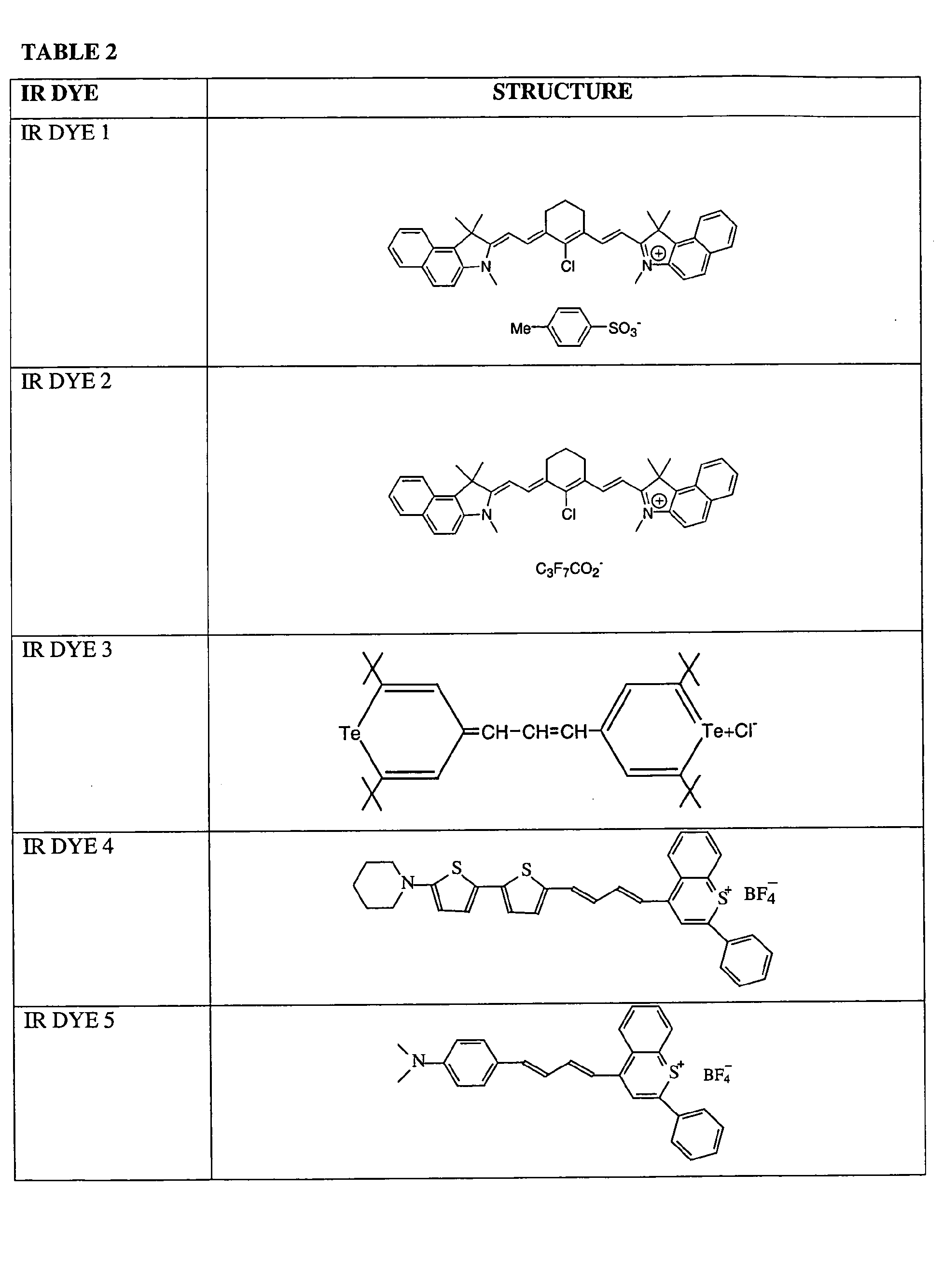


- IR Dyes 1-7 may be prepared using known procedures or obtained from several commercial sources (for example, Esprit, Sarasota, FL). IR dyes 8-14 may also be prepared using known procedures, as reported, for example, in U.S. Patent 4,871,656 (Parton et al.) and references reported therein (for example, U.S. Patent 2,895,955, U.S. Patent 3,148,187 and U.S. Patent 3,423,207). Other useful IR dyes are reported in U.S. Patent 5,605,780 (Burberry , et al). IR dyes 2 and 14 may be particularly useful for use in the present invention because these dyes do not tend to result in particle agglomeration in solution.
- Optionally, the photothermal conversion material may also be optimized to provide an improved thermally sensitive layer. In one embodiment, the photothermal conversion materials have a particle mean major dimension of no greater than 25 nm, more particularly 10-20 nm. Particles of this size may provide for improved absorption efficiency
- Optionally, the thermally sensitive layer of the present invention may include a polymeric binder. Suitable polymeric binders may be soluble or dispersible in substantially aqueous carriers. Examples of suitable polymeric binders include, but are not limited to, polyvinyl alcohols, polyvinyl pyrrolidones, polyethyleneimine (PEI), polyethyloxazoline, polyacrylamide, gelatin, polyacrylic acid, and salts, derivatives and mixtures thereof.
- The thermally sensitive layer may also optionally include one or more additives, including dispersing agents, humectants, biocides, surfactants, viscosity builders, colorants, pH adjusters, drying agents, defoamers or combinations thereof.
- The thermally sensitive compositions reported herein are generally applied to the substrate as a coating mixture including one or more suitable carriers. Suitable carriers may include both organic and aqueous solvents. More particularly, suitable carriers may include substantially aqueous carriers, including mixtures of water miscible organic liquids in aqueous solutions. A wide range of water miscible organic liquids may be used in the carrier of the present invention. A specific example of a suitable water miscible organic liquid is ethyl acetate.
- Suitable amounts of the polycyanoacrylate (or an aqueous dispersion thereof), the photothermal conversion material(s), the optional polymeric binder, and any other optional components may be combined with the carrier to form the coating mixture. A dispersing agent such as polyvinyl pyrrolidone may further be included in the coating mixture to reduce or prevent particle agglomeration. Thus, in one embodiment, polyvinyl pyrrolidone may act as a binder and/or a dispersing agent.
- The coating mixture may be applied to the surface of a suitable substrate by conventional methods, such as by spin coating, bar coating, gravure coating, knife coating or roller coating. The coating mixture may then be air dried, oven dried or radiation cured to form a thermally sensitive layer. This drying step may remove and/or evaporate portions of the carrier and/or certain optional components, such as the dispersing agent.
- The thermally sensitive layer of the resulting printing plate precursor may be imagewise exposed to thermal radiation, particularly to IR radiation, such that portions of the thermally sensitive layer exposed to the thermal radiation have a lower developability in fountain solution and/or printing ink than unexposed portions. More specifically, the radiation exposed portions adhere more strongly to the substrate such that the exposed portions are less easily developed than unexposed portions. An example of a suitable radiation source is the Creo Trendsetter 3230, which contains a laser diode that emits near infrared radiation at a wavelength of about 830 nm and is available from Creo Products Inc., Burnaby, BC, Canada. Other suitable radiation sources include the Crescent 42T Platesetter, an internal drum platesetter that operates at a wavelength of 1064 nm (Gerber Scientific, South Windsor, CT, USA), and the Screen PlatRite 4300 series or 8600 series (Screen, Chicago, Illinois). Additional useful radiation sources include direct imaging presses, which are able to image a plate while attached to a printing press cylinder. An example of a suitable direct imaging printing press is the Heidelberg SM74-DI press, available from Heidelberg, Dayton, Ohio.
- Advantageously, the resulting imaged printing plate precursor may be mounted in a printing press without first being subjected to a separate developing step. Instead, the imaged printing plate precursor may be developed "on press" by the fountain solution and/or ink used in conventional printing presses. Alternatively, in embodiments that utilize direct imaging presses, the printing plate precursor may be mounted on the direct image press, and may then be exposed to infrared radiation and developed.
- Suitable fountain solutions for developing the imaged printing plate precursor include substantially aqueous solvents, which may be alkaline, neutral or acidic. Suitable materials that may be added to the aqueous solution include a variety of alcohols and alcohol replacements. Specific examples of suitable fountain solutions include mixtures of the following components in water:
- Varn Litho Etch 142W + Varn PAR (alcohol sub) @ 3 oz / gal each (Varn International, Addison, IL);
- Varn Crystal 2500 (1-step) @ 4.5 oz /gal (Varn International);
- Varn Total Chromefree (@ 3.2 oz / gal) (Varn International) + Anchor ARS-F (@ 1.2 oz / gal) (Anchor, Orange Park, FL);
- Anchor Emerald JRZ (3 oz/gal) + Anchor ARS-ML (3.5 oz/gal) (Anchor);
- Rosos Plain KSP (@ 3-4 oz/ gal)+ Varn PAR @ 3 oz/gal each (Rosos Research Laboratories, Inc.);
- Rosos KSP 500 (@ 5 oz / gal) + RV1000 (@ 4 oz/gal) (Rosos Research Laboratories, Inc.);
- Prisco 3451U (@ 4 oz/gal) + Alkaless 3000 (@ 3 oz/gal) (Prisco, Newark, NJ);
- Prisco 4451 FK (@ 3 oz / gal) + Alkaless 6000 (@ 2 oz / gal) (Prisco);
- Prisco Webfount 300 (@ 2 oz / gal) + Alkaless 6000 (@ 3 oz / gal) (Prisco);
- Rycoline Green Diamond 251TW (@ 3 oz/gal) + Rycoline Green Diamond alcohol replacer (@ 2 oz/gal) (Rycoline, Chicago, IL);
- Allied PressControl EWS (@ 5 oz / gal) + HydroPlus (@ 1.5 oz / gal) (Allied Pressroom Chemistry, Hollywood, FL);
- RBP 910H (@ 3 oz / gal) + Aquanol 600 (@ 2 oz/gal) (RBP Chemical Technology, Milwaukee, WI);
- Allied Compliance ES (@ 3 oz / gal) + HydroDyne (@ 3 oz / gal) (Allied Pressroom Chemicals);
- The areas of the thermally sensitive layer not exposed to thermal radiation are removed after being contacted with fountain solution and/or ink as part of the normal printing process, while exposed areas remain adhered to the support to form an ink receptive image area. Ink applied to the image area may then be imagewise transferred to a suitable receiving material (such as cloth, paper, metal, glass or plastic) to provide one or more desired impressions. If desired, an intermediate blanket roller may be used to transfer the ink from the printing plate to the receiving material. The printing plate may be cleaned between impressions, if desired, using conventional cleaning methods.
- The present invention is further described in the following Examples.
- A polycyanoacrylate latex was formed by combining distilled water (1370g), glacial acetic acid (0.8g) and sodium benzene dodecyl sulfonate (1.5g), both available from Aldrich Chemical, Milwaukee, WI, in a 4 liter flask. After the sodium benzene dodecyl sulfonate dissolved in the water, a mixture of Loctite 85 cyanoacrylate monomer (155g) and glacial acetic acid (0.8g) was added dropwise over 5 minutes. Loctite 85 is available from Loctite Corp., Rocky Hill, CT and contains 80% methyl-2-cyanoacrylate monomers and 20% ethyl-2-cyanoacrylate monomers. A mildly exothermic polymerization occurred. The solution was heated to between 70 and 75 °C for 10 minutes and then cooled. The solution was then passed through a gauze filter, available from Great Lakes Filter Media, Detroit, MI.
- Particle size analysis using an ultrafine particle analyzer (UPA150) available from Microtrac, Inc., North Largo, FL, indicated a particle size range between 50 and 500 nm, with major populations at about 90 nm and about 260 nm and a mean particle size of about 90 nm. A coating mixture was then formed by combining the cyanoacrylate particles (76 parts), polyvinyl pyrrolidone binder (18 parts) and IR dye 14 (6 parts) in water. IR dye 14 is represented by the formula:

- Prior to being added to the coating mixture, IR dye 14 was pre-milled by blending the dye (5 parts) with water (95 parts) and Olin 10G (0.75 parts). Olin 10G is a nonylphenoxypoly (glycidol) surfactant, CIN 10040914, available from Arch Chemicals, Norwalk, CT. This dye blend was then combined with zirconia stabilized glass beads (1.8 mm in diameter) in a ratio of 313 ml of beads to 125g of dye blend. The dye blend and the beads were then loaded into a 625 ml glass jar and spun at 83 ft/min for 7 to 10 days (depending on the results of periodic particle size analysis) until substantial portions of the dye particles had a major dimension between 10 and 20 nm.
- The coating mixture was then applied to a grained and anodized aluminum substrate and dried to form a thermally sensitive layer. The resulting printing plate precursor was then imagewise exposed in a series of exposures at between about 150 and 300 mJ/cm2 (at intervals of 50) using an internal test pattern on a Creo Trendsetter 3230, a platesetter operating at a wavelength of 830 nm and available from Creo Products Inc., Burnaby, BC, Canada. Samples of the resulting imaged printing plate precursor were then mounted on an AB Dick duplicator press and a Komori press (Model S-26) to determine press performance.
- As illustrated in Figure 1a-c, SEM analysis indicates that printing plates formed according to Example 1 possessed an even coating with no uncoated areas. Additionally, during thermal imaging, the thermally sensitive layer exhibited improved ablation when compared to the thermally sensitive layer reported in Example 2 below. Ablation was measured gravimetrically, as well as by using a PET film to capture ablated material. Gravimetric analysis (using an imaging density of 325 mj/cm2) indicated a loss of thermally sensitive material of 116 mg/m2, which is about 13% of the total coating weight. Additionally, plate performance on press was satisfactory, and the plate exhibited no background sensitivity. Finally, the thermally sensitive layer exhibited satisfactory scratch resistance as indicated by durometer tests.
- Methyl cyanoacrylate (70 wt %) and ethyl cyanoacrylate (30 wt %) were copolymerized to form a cyanoacrylate polymer. IR dye 2 was pre-milled by blending the dye (5 parts) with water (95 parts) and Olin 10G (0.75 parts). IR dye 2 is represented by the formula:Olin 10G is a nonylphenoxypoly (glycidol) surfactant, CIN 10040914, available from Arch Chemicals, Norwalk, CT. This dye blend was then combined with zirconia stabilized glass beads (1.8 mm in diameter) in a ratio of 313 ml of beads to 125g of dye blend. The dye blend and the beads were then loaded into a 625 ml glass jar and spun at 83 ft/min for 7 to 10 days (depending on the results of periodic particle size analysis) until substantial portions of the dye particles had a major dimension between 10 and 20 nm.

- The solid polcyanoacrylate (76 parts) and IR dye 2 (6 parts) were then wet milled in a Molinex mill (available from Netzsch, Burlington, MA), with water being used as the carrier. The major dimension of the of the polycyanoacrylate particles (as measured with the Microtrac UPA of Example 1) ranged between about 400 and 10,000 nm, with a mean major dimension of about 610 nm. The mill discharge was blended with a polyvinyl pyrrolidone solution (18 parts of solid).
- The resulting coating mixture was then applied to a grained and anodized aluminum substrate and was dried to form a thermally sensitive layer. The resulting printing plate precursor was then imagewise exposed in a series of exposures between about 150 and 300 mJ/cm2 (at intervals of 50) using an internal test pattern on the Creo Trendsetter 3230. Samples of the resulting imaged printing plate precursor were then mounted on the AB Dick duplicator press and the Komori press of Example 1 to determine press performance.
- As illustrated in Figure 2a-c, SEM analysis indicated that printing plates formed as in Example 2 possessed a rough texture, including bare portions that revealed the substrate surface. Additionally, during IR exposure, the plate precursor exhibited a significant level of ablation. Ablation was assessed gravimetrically and using a PET film to capture ablated material. Gravimetric analysis (using an imaging density of 325 mj/cm2) indicated a loss of thermally sensitive material of about 200 mg/m2, which is about 17% of the total weight of the coating.
- A cyanoacrylate polymer was formed as in Example 1, except that the addition time of the cyanoacrylate monomer was shortened as much as practically possible. The resulting polycyanoacrylate particles had a major dimension ranging between about 20 and about 300 nm with a mean major dimension of 20.6 nanometers, as indicated by using the Microtrac UPA used in Example 1.
- Two coating mixtures were formed by combining polycyanoacrylate particles (76 parts), polyvinyl pyrrolidone binder (18 parts) and either IR dye 1 or IR Dye 11 (6 parts for each coating mixture) were then combined with water to form a coating mixture. Each coating mixture was then applied to a grained and anodized aluminum substrate and was dried to form a thermally sensitive layer.
- The resulting printing plate precursors were then imagewise exposed in a series of exposures between 150 and 300 mJ/cm2 (in intervals of 50) using an internal test pattern on the Creo Trendsetter 3230. Samples of the resulting imaged printing plate precursors were then mounted on an AB Dick duplicator press and a Komori press to determine press performance.
- The thermally sensitive layers formed from both coating mixtures exhibited a uniform coating over the substrate with no bare patches. However, the printing plates exhibited high background sensitivity (i.e. ink present in background) and scumming on press, which resulted in lower quality reproductions.
- As demonstrated by Examples 1-3, printing plates formed from thermally sensitive layers that contain polycyanoacrylate particles of optimized size (as reported in Example 1) possessed smooth continuous coatings, with improved ablation properties and low background sensitivity. In contrast, the thermally sensitive layers of Examples 2-3 possessed a discontinuous coating, exhibited significant ablation, and/or exhibited high background sensitivity.
Claims (37)
- A printing plate precursor comprising:a substrate; anda thermally sensitive layer applied onto a surface of the substrate, the thermally sensitive layer comprising polycyanoacrylate particles having a major dimension between about 50 and about 500 nm and a mean major dimension of no greater than 350 nm, and a photothermal conversion material.
- The printing plate precursor of claim 1 wherein the substrate is hydrophilic.
- The printing plate precursor of claim 1 or 2 wherein the substrate comprises an aluminum substrate or a polymer substrate.
- The printing plate precursor of claim 3 wherein the substrate comprises a polyester substrate.
- The printing plate precursor of any of claims 1 to 4 wherein the polycyanoacrylate particles have a major dimension between about 50 and about 400 nm.
- The printing plate precursor of any one of claims 1 to 5 wherein the cyanoacrylate polymer is thermally degradable below about 200°C.
- The printing plate precursor of any one of claims 1 to 6 wherein the dry weight ratio of the photothermal conversion material to the polycyanoacrylate particles is from about 0.02:1 to about 0.8:1.
- The printing plate precursor of any one of claims 1 to 7 wherein the thermally sensitive layer has a dry weight thickness of from about 0.05 to about 20 µm.
- The printing plate precursor of claim 8 wherein the thermally sensitive layer has a dry weight thickness of from about 0.5 to about 4 µm.
- The printing plate precursor of any one of claims 1 to 9 wherein the thermally sensitive layer has a dry weight of between about 0.5 and about 2.5 g/m2.
- The printing plate precursor of claim 10 wherein the thermally sensitive layer has a dry weight of between about 1.0 and about 2.0 g/m2.
- The printing plate precursor of any one of claims 1 to 11 wherein the polycyanoacrylate comprises poly(alkyl cyanoacrylate), poly(aryl cyanoacrylate), poly(alkoxyalkyl cyanoacrylate) or mixtures or derivatives thereof.
- The printing plate precursor of any one of claims 1 to 12 wherein the polycyanoacrylate comprises poly(methyl cyanoacrylate), poly(ethyl cyanoacrylate), poly(methyl cyanoacrylate-co-ethyl cyanoacrylate), poly(methoxyethyl cyanoacrylate), poly(n-butyl cyanoacrylate), poly(phenyl cyanoacrylate), poly(2-ethylhexyl cyanoacrylate), poly(methyl 2-cyanoacrylate-co-methoxyethyl 2-cyanoacrylate-co-ethyl-2-cyanoacrylate), poly(methyl 2-cyanoacrylate-co-methyl acrylate), or mixtures or derivatives thereof.
- The printing plate precursor of any one of claims 1 to 13 wherein the polycyanoacrylate comprises a copolymer including units derived from at least one cyanoacrylate polymerizable monomer and units derived from at least one non-cyanoacrylate monomer, wherein the units derived from the at least one cyanoacrylate polymerizable monomer comprise at least 50 mol % of the total units in the copolymer.
- The printing plate precursor of any one of claims 1 to 14 wherein the thermally sensitive layer further comprises a polymeric binder.
- The printing plate precursor of claim 15 wherein the polymeric binder comprises polyvinyl alcohol, polyvinyl pyrrolidone, polyethyleneimine, polyethyloxazoline, polyacrylamide, gelatin, polyacrylic acid, or mixtures thereof or derivatives thereof.
- The printing plate precursor of any one of claims 1 to 16 wherein the photothermal conversion material comprises a dye or a pigment.
- The printing plate precursor of any one of claims 1 to 17 wherein the photothermal conversion material comprises carbon black, Prussian Blue, Paris Blue, Milori Blue or a cyanine dye, bis(dichlorobenzene-1,2-thiol)nickel(2:1)tetrabutyl ammonium chloride, tetrachlorophthalocyanine aluminum chloride, or a compound represented by the formulas:


- The printing plate precursor of any one of claims 1 to 18 wherein the photothermal conversion material comprises particles having a major dimension no greater than 25 nm.
- The printing plate precursor of any one of claim 1 to 19 wherein the photothermal conversion material comprises particles having a major dimension between about 10 and about 20 nm.
- The printing plate precursor of any one of claims 1 to 20 wherein the photothermal conversion material is soluble in an aqueous solution.
- The printing plate precursor of claim 21 wherein the thermally sensiti further comprises a dispersant.
- The printing plate precursor of claim 22 wherein the dispersant comprises polyvinyl pyrrolidone.
- An imaged printing plate precursor comprising:a substrate;a thermally sensitive layer including:a radiation exposed image area comprising a polycyanoacrylate material; anda non-radiation exposed area comprising polycyanoacrylate particles and a photothermal conversion material, wherein the polycyanoacrylate particles have a major dimension between about 50 and about 500 nm and a mean major dimension of no greater than 350 nm.
- The printing element of claim 24 wherein the thermally sensitive layer further comprises a polymeric binder.
- A method of making a printing plate precursor comprising:providing a substrate;applying onto the substrate a coating mixture comprising a mixture ofa carrier, polycyanoacrylate particles having a major dimension between about 50 and about 500 nm and having a mean major dimension of no greater than 350 nm, anda photothermal conversion material; and drying the coating mixture to form a thermally sensitive layer on a surface of the substrate.
- The method of claim 26 wherein the carrier comprises an aqueous carrier, a water-miscible organic carrier or a combination thereof.
- The method of claim 26 or 27 wherein the carrier comprises a substantially aqueous carrier.
- The method of claim 26 wherein the carrier comprises ethyl acetate.
- The method of any one of claims 26 to 29 wherein the polycyanoacrylate particles are dispersed within the carrier.
- The method of any one of claims 26 to 30 wherein the photothermal conversion material is dispersed within the carrier.
- The method of any one of claims 26 to 31 wherein the coating mixture further comprises a dispersing agent.
- The method of claim 32 wherein the dispersing agent comprises polyvinyl pyrrolidone.
- The method of any one of claims 26 to 33 further comprising:imagewise exposing portions of the thermally sensitive layer to infrared radiation to form an imaged printing plate precursor, wherein exposed portions of the layer are less developable in a fountain solution, printing ink or both, than unexposed portions of the thermally sensitive layer.
- The method of claim 34 wherein the thermally sensitive layer is imagewise exposed to radiation after being placed on a direct imaging press.
- The method of claim 35 wherein after imagewise exposure, the thermally sensitive layer is exposed to fountain solution, printing ink or both, to remove unexposed portions of the thermally sensitive layer.
- The method of claim 34 further comprising:mounting the imaged printing plate precursor on a printing press; andexposing the thermally sensitive layer to fountain solution, printing ink or both, to remove unexposed portions of the thermally sensitive layer.
Applications Claiming Priority (2)
| Application Number | Priority Date | Filing Date | Title |
|---|---|---|---|
| US10/445,489 US6924080B2 (en) | 2003-05-27 | 2003-05-27 | Thermally sensitive compositions containing cyanoacrylate polymers |
| US445489 | 2003-05-27 |
Publications (3)
| Publication Number | Publication Date |
|---|---|
| EP1481800A2 true EP1481800A2 (en) | 2004-12-01 |
| EP1481800A3 EP1481800A3 (en) | 2005-08-24 |
| EP1481800B1 EP1481800B1 (en) | 2008-12-24 |
Family
ID=33131535
Family Applications (1)
| Application Number | Title | Priority Date | Filing Date |
|---|---|---|---|
| EP04012441A Expired - Fee Related EP1481800B1 (en) | 2003-05-27 | 2004-05-26 | Thermally sensitive compositions containing cyanoacrylate polymers |
Country Status (3)
| Country | Link |
|---|---|
| US (1) | US6924080B2 (en) |
| EP (1) | EP1481800B1 (en) |
| DE (1) | DE602004018565D1 (en) |
Cited By (5)
| Publication number | Priority date | Publication date | Assignee | Title |
|---|---|---|---|---|
| WO2008133807A1 (en) * | 2007-04-23 | 2008-11-06 | Eastman Kodak Company | Ablatable elements for making flexographic printing plates |
| WO2011051648A3 (en) * | 2009-10-29 | 2012-02-02 | The University Of Surrey | A method of making a patterned dried polymer and a patterned dried polymer |
| US8187793B2 (en) | 2007-04-23 | 2012-05-29 | Eastman Kodak Company | Ablatable elements for making flexographic printing plates |
| CN103721256A (en) * | 2012-10-15 | 2014-04-16 | 北京大学 | Near infrared photo-thermal conversion agent for tumor photo-thermal excision treatment |
| EP4129682A1 (en) | 2021-08-05 | 2023-02-08 | Agfa Offset Bv | A lithographic printing plate precursor |
Families Citing this family (3)
| Publication number | Priority date | Publication date | Assignee | Title |
|---|---|---|---|---|
| US7070902B2 (en) * | 2003-08-26 | 2006-07-04 | Eastman Kodak Company | Imageable elements containing cyanoacrylate polymer particles |
| US8618003B2 (en) | 2011-12-05 | 2013-12-31 | Eastman Kodak Company | Method of making electronic devices using selective deposition |
| WO2019004471A1 (en) * | 2017-06-30 | 2019-01-03 | 富士フイルム株式会社 | Lithographic printing original plate and method for producing lithographic printing plate |
Citations (3)
| Publication number | Priority date | Publication date | Assignee | Title |
|---|---|---|---|---|
| EP0795420A1 (en) * | 1996-03-12 | 1997-09-17 | Eastman Kodak Company | Lithographic printing plate adapted to be imaged by ablation |
| EP1219416A1 (en) * | 2000-12-20 | 2002-07-03 | Agfa-Gevaert | On-press development printing method using a negative working thermally sensitive lithographic printing plate |
| EP1260362A2 (en) * | 2001-05-24 | 2002-11-27 | Eastman Kodak Company | Negative-working thermal imaging member and methods of imaging and printing |
Family Cites Families (4)
| Publication number | Priority date | Publication date | Assignee | Title |
|---|---|---|---|---|
| FR1424008A (en) | 1963-12-05 | 1966-01-07 | Gevaert Photo Prod Nv | Method of recording information using heat and pressure sensitive material |
| US5605780A (en) * | 1996-03-12 | 1997-02-25 | Eastman Kodak Company | Lithographic printing plate adapted to be imaged by ablation |
| US6548222B2 (en) | 2000-09-06 | 2003-04-15 | Gary Ganghui Teng | On-press developable thermosensitive lithographic printing plates |
| US6482571B1 (en) | 2000-09-06 | 2002-11-19 | Gary Ganghui Teng | On-press development of thermosensitive lithographic plates |
-
2003
- 2003-05-27 US US10/445,489 patent/US6924080B2/en not_active Expired - Fee Related
-
2004
- 2004-05-26 EP EP04012441A patent/EP1481800B1/en not_active Expired - Fee Related
- 2004-05-26 DE DE602004018565T patent/DE602004018565D1/en active Active
Patent Citations (3)
| Publication number | Priority date | Publication date | Assignee | Title |
|---|---|---|---|---|
| EP0795420A1 (en) * | 1996-03-12 | 1997-09-17 | Eastman Kodak Company | Lithographic printing plate adapted to be imaged by ablation |
| EP1219416A1 (en) * | 2000-12-20 | 2002-07-03 | Agfa-Gevaert | On-press development printing method using a negative working thermally sensitive lithographic printing plate |
| EP1260362A2 (en) * | 2001-05-24 | 2002-11-27 | Eastman Kodak Company | Negative-working thermal imaging member and methods of imaging and printing |
Cited By (10)
| Publication number | Priority date | Publication date | Assignee | Title |
|---|---|---|---|---|
| WO2008133807A1 (en) * | 2007-04-23 | 2008-11-06 | Eastman Kodak Company | Ablatable elements for making flexographic printing plates |
| US8163465B2 (en) | 2007-04-23 | 2012-04-24 | Eastman Kodak Company | Ablatable elements for making flexographic printing plates |
| US8187794B2 (en) | 2007-04-23 | 2012-05-29 | Eastman Kodak Company | Ablatable elements for making flexographic printing plates |
| US8187793B2 (en) | 2007-04-23 | 2012-05-29 | Eastman Kodak Company | Ablatable elements for making flexographic printing plates |
| US8313887B2 (en) | 2007-04-23 | 2012-11-20 | Eastman Kodak Company | Ablatable elements for making flexographic printing plates |
| WO2011051648A3 (en) * | 2009-10-29 | 2012-02-02 | The University Of Surrey | A method of making a patterned dried polymer and a patterned dried polymer |
| CN102695990A (en) * | 2009-10-29 | 2012-09-26 | 萨里大学 | A method of making a patterned dried polymer and a patterned dried polymer |
| CN103721256A (en) * | 2012-10-15 | 2014-04-16 | 北京大学 | Near infrared photo-thermal conversion agent for tumor photo-thermal excision treatment |
| EP4129682A1 (en) | 2021-08-05 | 2023-02-08 | Agfa Offset Bv | A lithographic printing plate precursor |
| WO2023011820A1 (en) | 2021-08-05 | 2023-02-09 | Agfa Offset Bv | A lithographic printing plate precursor |
Also Published As
| Publication number | Publication date |
|---|---|
| EP1481800A3 (en) | 2005-08-24 |
| US6924080B2 (en) | 2005-08-02 |
| EP1481800B1 (en) | 2008-12-24 |
| DE602004018565D1 (en) | 2009-02-05 |
| US20040241571A1 (en) | 2004-12-02 |
Similar Documents
| Publication | Publication Date | Title |
|---|---|---|
| EP1767349B1 (en) | Method for making a lithographic printing plate | |
| EP1614538A2 (en) | Method for making a negative working, heat-sensitive lithographic printing plate precursor. | |
| JP2008509245A (en) | Thermally switchable imageable element comprising a betaine-containing copolymer | |
| EP2437940B1 (en) | On-press development of imaged elements | |
| EP1481800B1 (en) | Thermally sensitive compositions containing cyanoacrylate polymers | |
| US7226722B1 (en) | Imaging members with IR-sensitive polymer imageable layer | |
| JP2001162960A (en) | Original plate for heat sensitive lithographic printing plate | |
| EP1481801B1 (en) | Top coat layer for thermally sensitive printing plate precursors | |
| EP1510356B1 (en) | Imageable elements containing cyanoacrylate polymer particles | |
| US7371454B2 (en) | Imageable element comprising sulfated polymers | |
| EP1641619B1 (en) | Imageable element comprising sulfated polymers | |
| JP4127954B2 (en) | Heat sensitive planographic printing plate | |
| JP4116760B2 (en) | Planographic printing method | |
| US20040253533A1 (en) | Thermally sensitive composition containing nitrocellulose particles | |
| JP2001162963A (en) | Positive type heat sensitive lithographic printing original plate | |
| JP2001096938A (en) | Original plate for heat-sensitive lithographic printing block | |
| EP1604818A1 (en) | Negative working, heat-sensitive lithographic printing plate precursor | |
| JP2002283758A (en) | Original film for planographic printing plate | |
| JP2004142177A (en) | Substrate for lithographic form and lithographic original form | |
| EP1550551A2 (en) | Method for reducing start up blinding in no-process lithographic printing plates | |
| US20030235774A1 (en) | Thermally-convertible lithographic printing precursor with coalescence inhibitor | |
| JP2003039841A (en) | Original plate for lithographic printing plate | |
| JP2002029166A (en) | Original plate of heat sensitive lithographic printing plate and image forming method | |
| JP2000343850A (en) | Method for forming lithographic printing plate and original plate for lithographic printing plate | |
| JP2002362051A (en) | Original plate for lithographic printing plate |
Legal Events
| Date | Code | Title | Description |
|---|---|---|---|
| PUAI | Public reference made under article 153(3) epc to a published international application that has entered the european phase |
Free format text: ORIGINAL CODE: 0009012 |
|
| AK | Designated contracting states |
Kind code of ref document: A2 Designated state(s): AT BE BG CH CY CZ DE DK EE ES FI FR GB GR HU IE IT LI LU MC NL PL PT RO SE SI SK TR |
|
| AX | Request for extension of the european patent |
Extension state: AL HR LT LV MK |
|
| RIN1 | Information on inventor provided before grant (corrected) |
Inventor name: MULLIGAN, JAMES, LAURENCE Inventor name: CLARK ERIC Inventor name: BAILEY, DAVID, B. |
|
| RAP1 | Party data changed (applicant data changed or rights of an application transferred) |
Owner name: KODAK POLYCHROME GRAPHICS, LLC |
|
| PUAL | Search report despatched |
Free format text: ORIGINAL CODE: 0009013 |
|
| AK | Designated contracting states |
Kind code of ref document: A3 Designated state(s): AT BE BG CH CY CZ DE DK EE ES FI FR GB GR HU IE IT LI LU MC NL PL PT RO SE SI SK TR |
|
| AX | Request for extension of the european patent |
Extension state: AL HR LT LV MK |
|
| 17P | Request for examination filed |
Effective date: 20060214 |
|
| AKX | Designation fees paid |
Designated state(s): DE FR GB |
|
| RAP1 | Party data changed (applicant data changed or rights of an application transferred) |
Owner name: EASTMAN KODAK COMPANY |
|
| 17Q | First examination report despatched |
Effective date: 20070614 |
|
| GRAP | Despatch of communication of intention to grant a patent |
Free format text: ORIGINAL CODE: EPIDOSNIGR1 |
|
| GRAS | Grant fee paid |
Free format text: ORIGINAL CODE: EPIDOSNIGR3 |
|
| GRAA | (expected) grant |
Free format text: ORIGINAL CODE: 0009210 |
|
| AK | Designated contracting states |
Kind code of ref document: B1 Designated state(s): DE FR GB |
|
| REG | Reference to a national code |
Ref country code: GB Ref legal event code: FG4D |
|
| REF | Corresponds to: |
Ref document number: 602004018565 Country of ref document: DE Date of ref document: 20090205 Kind code of ref document: P |
|
| PLBE | No opposition filed within time limit |
Free format text: ORIGINAL CODE: 0009261 |
|
| STAA | Information on the status of an ep patent application or granted ep patent |
Free format text: STATUS: NO OPPOSITION FILED WITHIN TIME LIMIT |
|
| 26N | No opposition filed |
Effective date: 20090925 |
|
| PGFP | Annual fee paid to national office [announced via postgrant information from national office to epo] |
Ref country code: FR Payment date: 20130531 Year of fee payment: 10 |
|
| PGFP | Annual fee paid to national office [announced via postgrant information from national office to epo] |
Ref country code: DE Payment date: 20140602 Year of fee payment: 11 |
|
| REG | Reference to a national code |
Ref country code: FR Ref legal event code: ST Effective date: 20150130 |
|
| PG25 | Lapsed in a contracting state [announced via postgrant information from national office to epo] |
Ref country code: FR Free format text: LAPSE BECAUSE OF NON-PAYMENT OF DUE FEES Effective date: 20140602 |
|
| PGFP | Annual fee paid to national office [announced via postgrant information from national office to epo] |
Ref country code: GB Payment date: 20150424 Year of fee payment: 12 |
|
| REG | Reference to a national code |
Ref country code: DE Ref legal event code: R119 Ref document number: 602004018565 Country of ref document: DE |
|
| PG25 | Lapsed in a contracting state [announced via postgrant information from national office to epo] |
Ref country code: DE Free format text: LAPSE BECAUSE OF NON-PAYMENT OF DUE FEES Effective date: 20151201 |
|
| GBPC | Gb: european patent ceased through non-payment of renewal fee |
Effective date: 20160526 |
|
| PG25 | Lapsed in a contracting state [announced via postgrant information from national office to epo] |
Ref country code: GB Free format text: LAPSE BECAUSE OF NON-PAYMENT OF DUE FEES Effective date: 20160526 |