EP1478130A1 - Mobile body network - Google Patents
Mobile body network Download PDFInfo
- Publication number
- EP1478130A1 EP1478130A1 EP02700639A EP02700639A EP1478130A1 EP 1478130 A1 EP1478130 A1 EP 1478130A1 EP 02700639 A EP02700639 A EP 02700639A EP 02700639 A EP02700639 A EP 02700639A EP 1478130 A1 EP1478130 A1 EP 1478130A1
- Authority
- EP
- European Patent Office
- Prior art keywords
- mobile terminal
- tunnel
- packet
- subnet
- routers
- Prior art date
- Legal status (The legal status is an assumption and is not a legal conclusion. Google has not performed a legal analysis and makes no representation as to the accuracy of the status listed.)
- Withdrawn
Links
Images


Classifications
-
- H—ELECTRICITY
- H04—ELECTRIC COMMUNICATION TECHNIQUE
- H04W—WIRELESS COMMUNICATION NETWORKS
- H04W8/00—Network data management
- H04W8/02—Processing of mobility data, e.g. registration information at HLR [Home Location Register] or VLR [Visitor Location Register]; Transfer of mobility data, e.g. between HLR, VLR or external networks
- H04W8/04—Registration at HLR or HSS [Home Subscriber Server]
-
- H—ELECTRICITY
- H04—ELECTRIC COMMUNICATION TECHNIQUE
- H04L—TRANSMISSION OF DIGITAL INFORMATION, e.g. TELEGRAPHIC COMMUNICATION
- H04L63/00—Network architectures or network communication protocols for network security
- H04L63/02—Network architectures or network communication protocols for network security for separating internal from external traffic, e.g. firewalls
- H04L63/029—Firewall traversal, e.g. tunnelling or, creating pinholes
-
- H—ELECTRICITY
- H04—ELECTRIC COMMUNICATION TECHNIQUE
- H04L—TRANSMISSION OF DIGITAL INFORMATION, e.g. TELEGRAPHIC COMMUNICATION
- H04L63/00—Network architectures or network communication protocols for network security
- H04L63/16—Implementing security features at a particular protocol layer
- H04L63/166—Implementing security features at a particular protocol layer at the transport layer
-
- H—ELECTRICITY
- H04—ELECTRIC COMMUNICATION TECHNIQUE
- H04L—TRANSMISSION OF DIGITAL INFORMATION, e.g. TELEGRAPHIC COMMUNICATION
- H04L9/00—Cryptographic mechanisms or cryptographic arrangements for secret or secure communications; Network security protocols
- H04L9/40—Network security protocols
-
- H—ELECTRICITY
- H04—ELECTRIC COMMUNICATION TECHNIQUE
- H04W—WIRELESS COMMUNICATION NETWORKS
- H04W28/00—Network traffic management; Network resource management
- H04W28/16—Central resource management; Negotiation of resources or communication parameters, e.g. negotiating bandwidth or QoS [Quality of Service]
- H04W28/18—Negotiating wireless communication parameters
-
- H—ELECTRICITY
- H04—ELECTRIC COMMUNICATION TECHNIQUE
- H04W—WIRELESS COMMUNICATION NETWORKS
- H04W36/00—Hand-off or reselection arrangements
- H04W36/02—Buffering or recovering information during reselection ; Modification of the traffic flow during hand-off
-
- H—ELECTRICITY
- H04—ELECTRIC COMMUNICATION TECHNIQUE
- H04W—WIRELESS COMMUNICATION NETWORKS
- H04W40/00—Communication routing or communication path finding
- H04W40/34—Modification of an existing route
-
- H—ELECTRICITY
- H04—ELECTRIC COMMUNICATION TECHNIQUE
- H04W—WIRELESS COMMUNICATION NETWORKS
- H04W8/00—Network data management
- H04W8/26—Network addressing or numbering for mobility support
-
- H—ELECTRICITY
- H04—ELECTRIC COMMUNICATION TECHNIQUE
- H04W—WIRELESS COMMUNICATION NETWORKS
- H04W80/00—Wireless network protocols or protocol adaptations to wireless operation
- H04W80/04—Network layer protocols, e.g. mobile IP [Internet Protocol]
-
- H—ELECTRICITY
- H04—ELECTRIC COMMUNICATION TECHNIQUE
- H04W—WIRELESS COMMUNICATION NETWORKS
- H04W88/00—Devices specially adapted for wireless communication networks, e.g. terminals, base stations or access point devices
- H04W88/14—Backbone network devices
Definitions
- the present invention relates to a mobile network.
- Mobile IP is proposed as a method of, when a mobile terminal having an IP (internet protocol) address moves from a subnet that partially constitutes multiple IP networks to another subnet that partially constitutes the multiple IP networks, making it possible for the mobile terminal to maintain communications without interrupting sessions.
- IP internet protocol
- the mobile IP is defined by RFC (Request for Comment: Document including information about the Internet) 2002 of IETF (Internet Engineering Task Force: Internet technology special investigation committee).
- FIG. 17 An example of a mobile network using the mobile IP is shown in Fig. 17.
- reference numerals 1a and 1b denote IP networks
- reference numeral 2 denotes a network gateway
- reference numeral 3 denotes a mobile terminal
- reference numerals 4a, 4b, and 4c denote base stations
- reference numeral 5 denotes a foreign agent (FA)
- reference numeral 7 denotes a communication node (CN).
- FA foreign agent
- CN communication node
- the IP networks 1a and 1b are different IP networks that constitute a set of multiple IP networks, and operate according to different protocols. Each of the IP networks 1a and 1b has a plurality of routers. It is assumed that the IP network 1b shown in the figure is the Internet. The IP networks 1a and 1b are connected to each other by way of the network gateway 2 that makes these IP networks interwork.
- the mobile terminal 3 shown in the figure joins the IP network 1a, and obtains service provided by the IP network 1a under normal circumstances.
- the IP network 1a is a home network, i.e., a home domain for the mobile terminal 3 shown in the figure.
- the mobile terminal 3 has a function of communicating with another mobile terminal according to the mobile IP, and can obtain service even if it moves to another IP network included in the multiple IP networks.
- the FA 5 belongs to another subnet that partially constitutes the multiple IP networks, and provides an address (i.e., a care-of address) specifying the other subnet, to which the FA 5 belongs, to mobile terminals that have moved to the other subnet from still other subnets.
- the base stations 4a and 4b shown in the figure belong to the same subnet as that to which the FA 5 belongs.
- two or more subnets can be connected to the IP network 1a in the multiple IP networks.
- the HA 6 is placed within the home domain (e.g., the IP network 1a) of a mobile terminal (e.g., the mobile terminal 3).
- An IP address i.e., a home address
- the mobile terminal 3 has a storage unit (not shown in the figure) for storing the home address thereof
- the HA 6 has a storage unit (not shown in the figure) for storing the home addresses of all mobile terminals that join the subnet thereof.
- the HA 6 manages the address of another FA 5 that belongs to the other subnet where the mobile terminal 3 exists now as the location of the mobile terminal 3. Therefore, when the mobile terminal 3 detects that it has moved from an area that is under the charge of an old FA or the HA 6 to another area that is under the charge of a new FA 5, the mobile terminal 3 registers an address (referred to as a care-of address) specifying the new FA 5 as the address indicating the destination of the mobile terminal 3 in the HA 6 by way of the new FA 5.
- a care-of address an address specifying the new FA 5 as the address indicating the destination of the mobile terminal 3 in the HA 6 by way of the new FA 5.
- transfer of IP packets via an IP tunnel means transfer of the IP packets to an FA with encapsulation of IP packets that the HA has received into IP packets in another format having an IP header indicating a sending source address (e.g., the IP address specifying the HA 6) and a destination address (e.g., the care-of address specifying the FA 5).
- the FA retrieves an original IP packet from the encapsulated IP packet and then transfers it to the mobile terminal 3 that is the destination. This mechanism implements the mobile transmissivity of the mobile terminal 3 in accordance with the mobile IP.
- the HA 6 has a function of performing signaling processing according to the mobile IP (e.g., calling for the destination) and a function of performing IP tunnel transfer processing on user packets, the traffic and load are concentrated on the HA.
- the load is further concentrated on the HA. Therefore, the HA easily becomes a bottleneck on the network, and the trouble tolerance of the network is reduced.
- a further problem arises in the scalability of the multiple IP networks because the load on each HA increases with an increase in the number of subnets.
- the problem of such concentration of loads can arise in the FA 5 that makes a report about the roaming of a mobile terminal to the HA 6, and that decapsulates packets to be transmitted to the destination and transfers them to the destination.
- IP packets destined for a mobile terminal are basically transmitted to a corresponding FA by way of the HA.
- IP packets to be transmitted from a mobile terminal to the CN 7 are transmitted from the FA 5 to the network gateway 2 by way of one or more routers without using a reverse tunnel passing through the HA. Therefore, there causes a time delay different between the forward and backward directions of transmission because IP packets are passed through a route different depending on the direction of transmission of the IP packets, and this can result in the occurrence of trouble.
- the present invention is proposed to solve the above-mentioned problems, and it is therefore an object of the present invention to provide a mobile network that can prevent concentration of loads on one piece of equipment.
- a mobile network that is a subnet that partially constitutes multiple IP networks
- the mobile network including: a home agent server for managing identifiers of a plurality of mobile terminals each of which joins the mobile network; and a plurality of IP tunnel routers, when a mobile terminal moves another subnet that partially constitutes the multiple IP networks, the home agent server accepting destination information necessary for transmission of IP packets to the mobile terminal from the mobile terminal, and delivering IP tunnel setting information indicating the mobile terminal and the destination information to the plurality of IP tunnel routers, and, when then receiving an IP packet destined for the mobile terminal, each of the plurality of IP tunnel routers transferring the IP packet to the mobile terminal based on the IP tunnel setting information without making the IP packet go through the home agent server.
- each of the plurality of IP tunnel routers transfers an IP packet to the mobile terminal located outside the mobile network without making the IP packet go through the home agent server, the traffic and load of the home agent server can be reduced. Therefore, the mobile network can prevent the occurrence of a bottleneck point and can implement communications more smoothly as compared with prior art mobile networks, thereby improving the scalability of the multiple IP networks. Furthermore, even if trouble occurs in the home agent server or either of the plurality of IP tunnel routers, because transfer of IP packets can be implemented by using other nodes without troubles, the mobile IP network will have a large tolerance to troubles.
- each of the plurality of IP tunnel routers when receiving the IP tunnel setting information from the home agent server, registers information necessary for decapsulating encapsulated IP packets that originate from the mobile terminal associated with the IP tunnel setting information therein.
- the mobile network uses a reverse IP tunnel via which encapsulated IP packets are transmitted. Therefore, the mobile IP becomes applicable in the network in which backward-direction IP packet communications from the mobile terminal cause an access violation at an IP address.
- each of the plurality of IP tunnel routers has a function of insuring service quality
- the home agent server delivers service quality information indicating the request regarding service quality to the plurality of IP tunnel routers, and, when then receiving an IP packet destined for the mobile terminal, each of the plurality of IP tunnel routers transfers the IP packet based on the service quality information.
- the mobile network can set an IP tunnel flow in consideration of the quality of service.
- the mobile network further includes at least one buffer for temporarily storing IP packets, and, when recognizing occurrence of a handoff of the mobile terminal, the home agent server controls each of the plurality of IP tunnel routers and the buffer so that each of the plurality of IP tunnel routers stores a received IP packet destined for the mobile terminal in the buffer, when recognizing completion of the handoff of the mobile terminal, controls the buffer so that the buffer transfers the IP packet stored therein to the mobile terminal, and, when then receiving an IP packet destined for the mobile terminal, controls each of the IP tunnel routers so that each of the IP tunnel routers transfers the IP packet to the mobile terminal based on the IP tunnel setting information without making the IP packet go through the home agent server.
- the proper use of the buffer installed in the mobile network makes it possible to apply the mobile IP to a communication environment in which any loss of IP packets is not permitted.
- the mobile network further includes a bicasting unit that can create a copy of the received IP packet and can transmit both the received IP packet and the copy by way of different routes
- the home agent server controls each of the plurality of IP tunnel routers and the bicasting unit so that each of the plurality of IP tunnel routers transmits the IP packet by using the bicasting unit
- the bicasting unit transmits both the IP packet and the copy by way of two routes that are used before and after the handoff, respectively, according to control done by the home agent server, and characterized in that, when recognizing completion of the handoff of the mobile terminal, the home agent server controls each of the plurality of IP tunnel routers so that each of the plurality of IP tunnel routers terminates transferring of the IP packet to the bicasting unit, and, when then receiving an IP packet destined for the mobile terminal, controls each of the plurality of IP tunnel routers so that each of the IP tunnel routers transfers the IP packet
- the home agent server selects a subnet candidate that the mobile terminal can use based on control information received from the mobile terminal, selects an IP tunnel router associated with the selected subnet candidate, and transmits the IP tunnel setting information to the selected IP tunnel router.
- the home agent server transmits the IP tunnel setting information only to one or more IP tunnel routers which the mobile terminal can use, the entire number of control messages transmitted from the home agent server to the plurality of IP tunnel routers within the mobile network can be reduced.
- the home agent server determines a communication service that can be provided to the mobile terminal based on the control information received from the mobile terminal, selects a subnet candidate in which the communication service can be provided, selects an IP tunnel router associated with the selected subnet candidate, and transmits the IP tunnel setting information to the selected IP tunnel router.
- the home agent server transmits the IP tunnel setting information only to one or more IP tunnel routers which the mobile terminal can use, the entire number of control messages transmitted from the home agent server to the plurality of IP tunnel routers within the mobile network can be reduced.
- the home agent server delivers no IP tunnel setting information to the plurality of IP tunnel routers before catching an IP packet destined for the mobile terminal that has moved to the other subnet that partially constitutes the multiple IP networks.
- the home agent server doesn't send out the IP tunnel setting information when there is no necessity to transmit IP packets destined for the mobile terminal that has left from the mobile network. Therefore, the entire number of control messages transmitted from the home agent server to the plurality of IP tunnel routers can be reduced.
- the home agent server when catching an IP packet destined for the mobile terminal that has moved to the other subnet that partially constitutes the multiple IP networks, transfers the IP packet to the mobile terminal based on destination information. As a result, even when catching an IP packet destined for the mobile terminal that has left from the subnet to which the home agent server belongs, the home agent server can transfer this IP packet without loss of the IP packet.
- the home agent server selects a subnet candidate that the mobile terminal can use based on control information received from the mobile terminal, selects an IP tunnel router associated with the selected subnet candidate, and transmits the IP tunnel setting information to the selected IP tunnel router.
- the home agent server transmits the IP tunnel setting information only to an IP tunnel router which the mobile terminal can use, the entire number of control messages transmitted from the home agent server to the plurality of IP tunnel routers can be reduced.
- the home agent server when catching an IP packet destined for the mobile terminal that has moved to the other subnet from an IP tunnel router that is not selected, transmits the IP tunnel setting information to the IP tunnel router. As a result, even when receiving an IP packet from an IP tunnel router not selected, an appropriate IP tunnel can be established.
- a mobile network that is a subnet that partially constitutes multiple IP networks
- the mobile network including: a foreign agent server for managing an identifier of a mobile terminal that does not join the mobile network and that can obtain service provided by the mobile network; and an IP tunnel router, when the mobile terminal moves from another subnet that partially constitutes the multiple IP networks to the mobile network, the foreign agent server transmits destination information necessary for transmission of IP packets to the mobile terminal to a subnet that the mobile terminal originally joins, and, when then receiving an IP packet destined for the mobile terminal, the IP tunnel router transfers the IP packet to the mobile terminal without making the IP packet go through the foreign agent server.
- an IP tunnel router can transfer IP packets to the mobile terminal that roams into the mobile network without making them pass through the foreign agent server, the traffic carried by and the load imposed on the foreign agent server can be reduced.
- Fig. 1 shows multiple IP networks including a mobile network in accordance with embodiment 1 of the present invention.
- reference numerals 1a and 1b denote IP networks
- reference numeral 2 denotes a network gateway
- reference numeral 3 denotes a mobile terminal
- reference numerals 4a, 4b, and 4c denote base stations
- reference numerals 5a and 5b denote foreign agents (FAs)
- reference numeral 7 denotes a communication node (CN)
- reference numeral 8 denotes a virtual home agent (HA)
- reference numeral 9 denotes a home agent (HA) server
- reference numerals 10a to 10c denote IP tunnel routers
- reference numerals 11a and 11b denote routers.
- the IP networks 1a and 1b are different IP networks each of which partially constitutes multiple IP networks, and operate according to different protocols. Each of the IP networks 1a and 1b has a plurality of routers. It is assumed that the IP network 1b shown in the figure is the Internet. The IP networks 1a and 1b are connected to each other by way of the network gateway 2 that makes these IP networks interwork.
- the mobile terminal 3 shown in the figure joins the IP network 1a, and obtains service provided by the IP network 1a under normal circumstances.
- the IP network 1a is a home network, i.e., a home domain for the mobile terminal 3 shown in the figure.
- the mobile terminal 3 has a function of communicating with another mobile terminal according to mobile IP, and, even if the mobile terminal 3 moves to another IP network included in the multiple IP networks, can obtain service provided by the other IP network.
- Each of the FAs 5a and 5b belongs to another subnet that partially constitutes the multiple IP networks, and provides an address (i.e., a care-of address) specifying the other subnet, to which each of the FAs belongs, to mobile terminals that have moved to the other subnet from other subnets.
- Each of the FAs 5a and 5b is disposed in control equipment of the corresponding subnet to which each of the FAs belongs, e.g., a network gateway that connects the IP network 1b with the subnet so as to make them interwork.
- the base stations 4a and 4b shown in the figure belong to the same subnet as that to which the FA 5a belongs, and the base station 4c belongs to the same subnet as that to which the FA 5b belongs. Although only the two FAs 5a and 5b are shown in Fig. 1, three or more subnets can be connected to the IP network 1a in the multiple IP networks.
- the virtual HA 8 is disposed within the home domain (e.g., the IP network 1a) of a mobile terminal (e.g., the mobile terminal 3).
- the virtual HA 8 is provided with the HA server 9 and the plurality of IP tunnel routers 10a to 10c.
- the HA server 9 has a function similar to that of Media Gateway Controller (MGC) described according to MEGACO (Multimedia Gateway Control Protocol) defined by IETF, and each of the plurality of IP tunnel routers 10a to 10c has a function similar to that of Media Gateway (MG).
- MMC Media Gateway Controller
- MEGACO Multimedia Gateway Control Protocol
- each of the plurality of IP tunnel routers 10a to 10c has a function similar to that of Media Gateway (MG).
- the HA server 9 and the plurality of IP tunnel routers 10a to 10c implement communications similar to those in accordance with MEGACO (RFC3015) defined by IETF in cooperation with each other.
- the plurality of IP tunnel routers 10a to 10c and the routers 11a and 11b are provided for transfer of IP packets, and the plurality of IP tunnel routers 10a to 10c are connected directly to a plurality of pieces of control equipment respectively disposed in other subnets, i.e., the FAs 5a and 5b and the network gateway 2, respectively.
- the plurality of IP tunnel routers 10a to 10c are located on the edge of this mobile network, i.e., the IP network 1a.
- Each of the plurality of IP tunnel routers 10a to 10c transfers IP packets transmitted thereto from a subnet other than the IP network 1a to another router, and transfers IP packets transmitted thereto from another router to a subnet other than the IP network 1a.
- each of the routers 11a and 11b transfers IP packets from mobile terminals that currently exist in the IP network 1a to another router, and transfers IP packets from another router to mobile terminals that currently exist in the IP network 1a.
- Each of the plurality of IP tunnel routers 10a to 10c can also have the same function as such a function of each of the routers 11a and 11b.
- IP address i.e., a home address
- a storage unit (not shown in the figure) of the mobile terminal 3 stores the home address of the mobile terminal 3 therein
- a storage unit (not shown in the figure) of the HA server 9 stores the home addresses of all mobile terminals that join the subnet to which the HA server belongs.
- the address of an FA 5 belonging to a subnet where the mobile terminal 3 exists is managed, as the location of the mobile terminal 3, by the whole of the virtual HA 8. Therefore, when detecting that the mobile terminal 3 has moved to an area that is under the charge of a new FA (e.g., the FA 5a) from an area that is under the charge of an old FA or the virtual HA8, the mobile terminal 3 registers an address (referred to as a care-of address) specifying the new FA 5a, as the address of the destination of the mobile terminal, in the HA server 9 of the virtual HA 8 by way of the new FA 5a.
- a new FA e.g., the FA 5a
- the mobile terminal 3 registers an address (referred to as a care-of address) specifying the new FA 5a, as the address of the destination of the mobile terminal, in the HA server 9 of the virtual HA 8 by way of the new FA 5a.
- the HA server 9 notifies the care-of address to all of the plurality of IP tunnel routers 10a to 10c.
- Each of the plurality of IP tunnel routers 10a to 10c has a storage unit for storing the care-of address of each mobile terminal that has moved from the IP network 1a to another subnet.
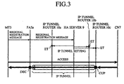
- Fig. 3 is a control flow diagram showing a sequence of control executed among various nodes in the multiple IP networks including the mobile network in accordance with embodiment 1. Assume that the mobile network operates according to the mobile IP of IPv4 (Internet Protocol version 4), as will be explained below.
- IPv4 Internet Protocol version 4
- the mobile terminal (MT) 3 has moved from an area that is under the charge of an old FA or the virtual HA8 to an area that is under the charge of a subnet corresponding to a new FA (e.g., the FA 5a).
- the mobile terminal 3 transmits a regional registration message which complies with the mobile IP to the FA 5a. Because the home address of the mobile terminal 3 is indicated by this regional registration message, the FA 5a recognizes that the mobile terminal 3 having this home address has moved to the area that is under the charge of the subnet associated with the FA 5a itself.
- the FA 5a When receiving the regional registration message, the FA 5a assigns an identifier effective in the subnet associated therewith to the mobile terminal 3 by performing internal processing, and transmits a regional registration message of another type (i.e., a second regional registration message) to the HA server 9.
- This second regional registration message indicates the home address of the mobile terminal 3 and an IP address (i.e., a care-of address) specifying the FA 5a. Therefore, the HA server 9 recognizes that the mobile terminal 3 can obtain service from the FA 5a.
- the HA server 9 When receiving the second regional registration message, the HA server 9 updates registered information about the mobile terminal 3 stored in the storage unit thereof according to this second regional registration message. Furthermore, the HA server 9 delivers IP tunnel setting information indicating the mobile terminal 3 and the subnet from which the mobile terminal 3 newly obtains service to all of the plurality of IP tunnel routers 10a to 10c located on the edge of the IP network 1a to which the HA server 9 belongs.
- the IP tunnel setting information indicates the home address of the mobile terminal 3 and the IP address (i.e., the care-of address) specifying the FA 5 a. Therefore, each of the plurality of IP tunnel routers 10a to 10c recognizes that the mobile terminal 3 can obtain service provided by the FA 5a.
- each of the plurality of IP tunnel routers 10a to 10c updates (designated by reference character ET shown in Fig. 3) a tunnel processing information file stored in the storage unit thereof according to the IP tunnel setting information.
- Fig. 4 is a diagram showing an example of the tunnel processing information file registered to each of the plurality of IP tunnel routers 10a to 10c included in the mobile network in accordance with embodiment 1 of the present invention.
- the tunnel processing information file has fields in which a destination address, processing, an encapsulated destination address, and an encapsulated sending source address are described, as shown in Fig. 4.
- the home address of each mobile terminal e.g., the mobile terminal 3 that joins the IP network 1a and that currently obtains service provided by another subnet is described as the destination address.
- Encapsulation is described as the nature of the processing.
- the care-of address of an FA e.g., the FA 5a
- the IP address of the IP tunnel router 10a, 10b or 10c that has generated the tunnel processing information file is described as the encapsulated sending source address.
- the IP address of the HA server 9 can be used instead of the IP address of the IP tunnel router 10a, 10b, or 10c.
- the tunnel processing information file has a field in which the sending source address is described, and which is not used.
- the destination address field of the tunnel processing information file defines a condition for execution of the tunnel processing using encapsulation.
- each of the plurality of IP tunnel routers 10a to 10c carries out the tunnel processing using encapsulation.
- each of the plurality of IP tunnel routers 10a to 10c encapsulates each received IP packet into an IP packet in another format, the encapsulated IP packet having an IP header specifying the encapsulated sending source address (i.e., an IP address specifying the IP tunnel router 10a, 10b or 10c or an IP address specifying the HA server 9) and the encapsulated destination address (i.e., a care-of address specifying an FA, e.g., the FA 5).
- Each of the plurality of IP tunnel routers then transmits the encapsulated IP packet to the FA associated with the encapsulated destination address, e.g., the FA 5.
- each of the plurality of IP tunnel routers 10a to 10c can transfer IP packets to the mobile terminal 3 that has caused the updating of the tunnel processing information file by using an IP tunnel.
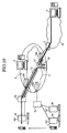
- the CN 7 issues IP packets destined for the mobile terminal 3 (see Figs. 2 and 3) as the mobile terminal 3 accesses the CN 7 connected to the Internet (i.e., the IP network 1b), as shown in Fig. 3, or that the CN 7 voluntarily transmits IP packets to the mobile terminal 3 without responding to such an access or a request for transmission of data.
- the IP packets destined for the mobile terminal 3 and sent from the CN 7 are received by the IP tunnel router 10c by way of the network gateway 2.
- the IP tunnel router 10c refers to the destination address included in the header of each IP packet, recognizes that this destination address is described in the destination address field of the tunnel processing information file, and encapsulates (designated by reference character CUP shown in Fig. 3) each IP packet, and transfers the encapsulated IP packets to the FA 5a.
- Reference numeral 12 shown in Fig. 2 denotes a virtual IP tunnel extending from the IP tunnel router 10c to the FA 5a.
- each of the plurality of IP tunnel routers 10a to 10c included in the IP network 1a can transfer IP packets sent from the CN 7 to the subnet where the mobile terminal 3 currently exists by way of the IP tunnel 12 based on the IP tunnel setting information without making them go through the HA server 9.
- the FA 5a then decapsulates (designated by reference character DEC shown in Fig. 3) the encapsulated IP packets into IP packets in their original format, and delivers the decapsulated IP packets to the mobile terminal 3 by using an identifier effective in the subnet associated therewith.
- the mobile terminal 3 can transmit IP packets to the CN 7 by using a method of transmitting IP packets by way of a normal routing path.
- Fig. 5 is a flow chart showing the operation of each of the plurality of IP tunnel routers 10a to 10c in accordance with the embodiment 1.
- Each of the plurality of IP tunnel routers 10a to 10c starts this operation as a sub routine when receiving IP packets.
- each of the plurality of IP tunnel routers 10a to 10c determines whether it has received the IP packet from an external interface (e.g., the network gateway 2, or the FA 5a or 5b) as shown in step ST1. Reception of an IP packet from an external interface means that there is a sending source node outside the subnet where the plurality of IP tunnel routers exist.
- an external interface e.g., the network gateway 2, or the FA 5a or 5b
- each of the plurality of IP tunnel routers 10a to 10c determines that it has received no IP packet from any external interface, it can be assumed that each of the plurality of IP tunnel routers 10a to 10c has received an IP packet from an internal interface (e.g., the router 11a or 11b), that is, there is a sending source node within the subnet where each of the plurality of IP tunnel routers 10a to 10c is installed.
- an internal interface e.g., the router 11a or 11b
- each of the plurality of IP tunnel routers 10a to 10c When receiving an IP packet from an external interface, each of the plurality of IP tunnel routers 10a to 10c, in step ST2, refers to the destination address included in the header of the received IP packet, and determines whether or not this destination address is described in the destination address field of the tunnel processing information file registered therein. In other words, each of the plurality of IP tunnel routers 10a to 10c determines whether or not the mobile terminal that is the destination is obtaining service provided by a subnet other than the subnet where each of the plurality of IP tunnel routers 10a to 10c is installed.
- each of the plurality of IP tunnel routers 10a to 10c encapsulates the received IP packet as mentioned above (in step ST3), and, after that, transfers the encapsulated IP packet to the FA associated with the encapsulated destination address (in step ST4). Therefore, the FA can deliver the IP packet to the mobile terminal that is the destination located in the subnet associated therewith and placed outside the IP network 1a.
- each of the plurality of IP tunnel routers determines an internal interface (e.g., the router 11a or 11b) that is the routing destination of the received IP packet (in step ST5), and, after that, transfers the IP packet to the internal interface (in step ST6). Therefore, the IP packet is delivered from the internal interface to the mobile terminal that is the destination and currently exists in the subnet corresponding to the IP network 1a.
- an internal interface e.g., the router 11a or 11b
- each of the plurality of IP tunnel routers 10a to 10c advances to step ST7 when determining that it has not received any IP packet from an external interface, in step ST1.
- each of the plurality of IP tunnel routers 10a to 10c determines an interface that is the routing destination of the received IP packet (in step ST7), and, after that, transfers the IP packet to the interface (in step ST8).
- each of the plurality of IP tunnel routers 10a to 10c transfers IP packets to the mobile terminal 3 located outside the IP network 1a without making them go through the HA server 9, the traffic carried by and load imposed on the HA server 9 can be reduced. Therefore, the mobile network can prevent the occurrence of a bottleneck point and can implement communications more smoothly as compared with prior art mobile networks, thereby improving the scalability of the multiple IP networks. Furthermore, even if trouble occurs in the HA server 9 or either of the plurality of IP tunnel routers 10a to 10c, because transfer of IP packets can be implemented by using other nodes without troubles, the mobile IP network will have a large tolerance to troubles. Furthermore, because each of the plurality of IP tunnel routers 10a to 10c located on the edge of the network can carry out the tunnel processing, optimum routing can be implemented within the home network.
- the mobile network of embodiment 1 operates, as mentioned above, according to the mobile IP of IPv4 (Internet Protocol version 4).
- the mobile network of embodiment 1 can be so constructed as to operate according to the mobile IP of IPv6 (Internet Protocol version 6).
- IPv4 Internet Protocol version 4
- IPv6 Internet Protocol version 6
- IP packets are transmitted from a subnet to which a mobile terminal originally belongs to the mobile terminal that has moved to an outside subnet by way of an FA according to IPv4
- a temporary, global address i.e., an address effective in any subnet
- IP packets are then transmitted to the mobile terminal with the temporary, global address without being passed through any FA.
- the temporary, global address of the mobile terminal (e.g., the mobile terminal 3) is notified to the HA server 9 of the virtual HA 8 which the mobile terminal originally joins, and is further notified to the plurality of IP tunnel routers 10a to 10c.
- each of the plurality of IP tunnel routers 10a to 10c encapsulates the IP packet and transfers it directly to the mobile terminal.
- each of the plurality of IP tunnel routers 10a to 10c establishes an IP tunnel between itself and the mobile terminal that is the destination of the IP packet.
- the encapsulated destination address is the temporary, global address of the mobile terminal.
- IP packets are transmitted directly to the mobile terminal from the sending source node.
- Mobile networks in accordance with other embodiments described later can operate according to IPv6.
- the mobile network uses one virtual HA.
- the mobile network can use an MAP (Mobility Anchor Point) instead of one virtual HA.
- the MAP is a virtual home agent being adopted into DRiVE (Dynamic Radio for IP-Services in Vehicular Environments) and HMIPv6 (Hierarchical Mobile IPv6).
- DRiVE Dynamic Radio for IP-Services in Vehicular Environments
- HMIPv6 Hierarchical Mobile IPv6
- a plurality of MAPs are disposed in one core network.
- the functionality of each MAP is spread over one HA server and a plurality of IP tunnel routers.
- Fig. 6 shows a flow of user data between a mobile terminal 3 and a CN 7 in a mobile network in accordance with embodiment 2 of the present invention.
- the mobile network in accordance with embodiment 2 of the present invention and entire multiple IP networks can be the same as those as shown in Fig. 1.
- An HA server 9, a plurality of IP tunnel routers 10a to 10c, FAs 5a and 5b have additional functions described later, respectively.
- reference numeral 13 denotes a virtual reverse IP tunnel extending from the FA 5a to the IP tunnel router 10a.
- the reverse IP tunnel 13 via which encapsulated IP packets are transmitted is used as a route from an FA (e.g., the FA 5a) to an IP tunnel router (e.g., the IP tunnel router 10a).
- Other operations, i.e., forward-direction communications from the CN7 to the mobile terminal 3 are conducted in the same way as explained in Embodiment 1.
- the mobile terminal 3 when the mobile terminal 3 detects that the mobile terminal 3 has moved from another area that is under the charge of an old FA or a virtual HA 8 to an area that is under the charge of a subnet associated with a new FA (e.g., the FA 5a), the mobile terminal 3 transmits a regional registration message that complies with the mobile IP to the FA 5a. Then, the FA 5a assigns an identifier effective in the subnet associated therewith to the mobile terminal 3 by carrying out internal processing, and transmits a second regional registration message to the HA server 9 (see Fig. 3), like that of above-mentioned embodiment 1.
- the FA 5a assigns an identifier effective in the subnet associated therewith to the mobile terminal 3 by carrying out internal processing, and transmits a second regional registration message to the HA server 9 (see Fig. 3), like that of above-mentioned embodiment 1.
- the HA server 9 When receiving the second regional registration message, the HA server 9 updates registered information about the mobile terminal 3 stored in a storage unit thereof according to this second regional registration message. The HA server 9 then delivers IP tunnel setting information indicating the mobile terminal 3 and the subnet from which the mobile terminal 3 newly obtains service to all of the plurality of IP tunnel routers 10a to 10c located on the edge of the IP network 1a to which the HA server 9 belongs.
- the IP tunnel setting information indicates the home address of the mobile terminal 3 and an IP address (i.e., a care-of address) specifying the FA 5a, like that as mentioned in Embodiment 1. Therefore, each of the plurality of IP tunnel routers 10a to 10c recognizes that the mobile terminal 3 can obtain service provided by the FA 5a.
- each of the plurality of IP tunnel routers 10a to 10c updates (designated by reference character ET shown in Fig. 3) a tunnel processing information file stored in a storage unit thereof according to the IP tunnel setting information.
- the tunnel processing information file in accordance with this embodiment has information used for decapsulation as shown in Fig. 7 in addition to the information used for encapsulation as mentioned in Embodiment 1 and as shown in the Fig. 4.
- each of the plurality of IP tunnel routers 10a to 10c updates the information used for encapsulation as shown in Fig. 4 and further updates the information used for decapsulation as shown in Fig. 7.
- the tunnel processing information file has fields in which a destination address, processing, an encapsulated destination address, and an encapsulated sending source address are described, as shown in Fig. 7. However, the fields representing the encapsulated destination address and the encapsulated sending source address are not used for decapsulation.
- the IP address of the HA server 9 is described as the destination address.
- the IP address of either of the plurality of IP tunnel routers 10a, 10b and 10c can be described as the destination address.
- the IP address (i.e., the care-of address) of the FA that has transmitted the above-mentioned second regional registration message is described as the sending source address. "Decapsulation" is described as the nature of the processing.
- each FA when receiving an IP packet destined for a destination that exists in an outside subnet, each FA encapsulates the IP packet. Concretely, each FA uses the IP address (i.e., the care-of address) thereof as the encapsulated sending source address, and provides an IP packet header that uses the IP address of the HA server 9 or either of the plurality of IP tunnel routers 10a to 10c as the encapsulated destination address to the received IP packet so as to generate an encapsulated IP packet. The FA then transmits the encapsulated IP packet to the encapsulated destination address by using the reverse IP tunnel 13.
- IP address i.e., the care-of address
- the IP packet having, as the sending source address, the care-of address in the IP header and, as the destination address, the IP address of the HA server 9 or either of the plurality of IP tunnel routers 10a to 10c is an encapsulated IP packet.
- Each of the plurality of IP tunnel routers 10a to 10c can refer to the packet header of each IP packet received from an external interface (e.g., the network gateway 2 or the FA 5a or 5b), and can determine whether the destination address described in this packet header is the IP address of the HA server 9 or either of the plurality of IP tunnel routers 10a to 10c. As an alternative, each of the plurality of IP tunnel routers 10a to 10c can determine whether or not the sending source address described in the packet header of each IP packet received from the external interface is a care-of address. Because each received IP packet is an encapsulated IP packet when determined in the affirmative in either of those determination processes, each of the plurality of IP tunnel routers 10a to 10c decapsulates this IP packet.
- an external interface e.g., the network gateway 2 or the FA 5a or 5b
- the destination address field and sending source address field of the tunnel processing information file as shown in Fig. 7 define conditions under which each of the plurality of IP tunnel routers 10a to 10c carries out the decapsulation processing on each encapsulated IP packet received by way of the reverse IP tunnel 13. After that, each of the plurality of IP tunnel routers 10a to 10c retrieves the original IP packet from each encapsulated IP packet (i.e., decapsulates each encapsulated IP packet), and transfers the original IP packet to the destination address indicated by the packet header of the original IP packet.
- Fig. 8 is a flow chart showing the operation of each of the plurality of IP tunnel routers 10a to 10c in accordance with embodiment 2. Each of the plurality of IP tunnel routers 10a to 10c starts this operation as a sub routine when receiving IP packets.
- each of the plurality of IP tunnel routers 10a to 10c determines whether it has received the IP packet from an external interface (e.g., the network gateway 2, or the FA 5a or 5b) as shown in step ST1. Reception of IP packets from an external interface means that there is a sending source node outside the subnet where each of the plurality of IP tunnel routers is installed.
- an external interface e.g., the network gateway 2, or the FA 5a or 5b
- each of the plurality of IP tunnel routers 10a to 10c determines that it has received no IP packet from any external interface, it can be assumed that each of the plurality of IP tunnel routers 10a to 10c has received an IP packet from an internal interface (e.g., the router 11a or 11b), that is, there is a sending source node within the subnet where each of the plurality of IP tunnel routers is installed.
- an internal interface e.g., the router 11a or 11b
- each of the plurality of IP tunnel routers 10a to 10c in step ST2, refers to the destination address included in the header of the received IP packet, and determines whether or not this destination address is described in the destination address field of the tunnel processing information file registered therein.
- each of the plurality of IP tunnel routers advances to step ST13 when determined, in step ST12, in the affirmative.
- Each of the plurality of IP tunnel routers determines whether "encapsulation” or "decapsulation” is described as the nature of the processing associated with the destination address included in the tunnel processing information file.
- each of the plurality of IP tunnel routers advances to step ST14 in which each of the plurality of IP tunnel routers encapsulates the received IP packet as mentioned above, and, after that, transfers the encapsulated IP packet to an FA associated with the encapsulated destination address (in step ST15). Therefore, the received IP packet can be delivered to the mobile terminal that is the destination existing in a subnet located outside the IP network 1a by the FA.
- each of the plurality of IP tunnel routers has received the IP packet by way of the reverse IP tunnel 13.
- each of the plurality of IP tunnel routers then advances to step ST16 in which each of the plurality of IP tunnel routers decapsulates the received IP packet (i.e., the encapsulated IP packet), as mentioned above, and each of the plurality of IP tunnel routers determines an interface that is the routing destination of the retrieved IP packet (in step ST17), and, after that, transfers the retrieved IP packet to the interface (in step ST21).
- IP packets can be delivered from the interface to the CN 7 connected to the IP network 1b.
- each of the plurality of IP tunnel routers determines an internal interface (e.g., the router 11a or 11b) that is the routing destination of the received IP packet (in step ST19), and, after that, transfers the received IP packet to the internal interface (in step ST20).
- an internal interface e.g., the router 11a or 11b
- each of the plurality of IP tunnel routers advances to step ST21 when determined, in step ST11, in the negative.
- each of the plurality of IP tunnel routers determines an interface that is the routing destination of the received IP packet (in step ST21), and, after that, transfers the IP packet to the interface (in step ST22).
- the mobile network uses the reverse IP tunnel 13 via which encapsulated IP packets are transmitted as a route from an FA (e.g., the FA 5a) to an IP tunnel router (e.g., the IP tunnel router 10a). Therefore, the mobile IP becomes applicable in the network in which backward-direction IP packet communications from the mobile terminal 3 to the CN 7 cause an access violation at an IP address.
- an FA e.g., the FA 5a
- an IP tunnel router e.g., the IP tunnel router 10a
- Fig. 9 shows multiple IP networks having a mobile network in accordance with embodiment 3 of the present invention.
- reference numeral 20 denotes an MPLS (MultiProtocol Label Switching) network
- reference numerals 20a to 20c denote IP tunnel routers.
- the IP network 1a of Fig. 1 is replaced by the MPLS network 20, and the plurality of IP tunnel routers 10a to 10c are replaced by the plurality of IP tunnel routers 20a to 20c.
- Other nodes are the same as those as shown in Fig. 1.
- a virtual HA 8 is provided with an HA server 9 and the plurality of IP tunnel routers 20a to 20c.
- each node as shown in Fig. 9 operates in the same way that a corresponding node of above-mentioned embodiment 1 or 2 does.
- each of the plurality of IP tunnel routers 20a to 20c has an MPLS edge function.
- Mobile terminals joining the MPLS network 20, which is their home network, and including a mobile terminal (e.g., a mobile terminal 3) that has moved to another subnet that partially constitutes the multiple IP networks can transmit a request regarding QoS to the HA server 9.
- the mobile terminal can incorporate this QoS request into a regional registration message that complies with the mobile IP.
- an FA e.g., an FA 5a
- an FA belonging to the other subnet transmits a second regional registration message specifying a QoS request to the HA server 9.
- each mobile terminal can transmit a QoS request to the HA server 9 according to RSVP (Resource Reservation Protocol) in a timely manner.
- RSVP Resource Reservation Protocol
- the HA server 9 When accepting such a QoS request, the HA server 9 updates registered information about the mobile terminal 3, which is stored in a storage unit thereof, according to the QoS request. Furthermore, the HA server 9 delivers QoS information (i.e., service quality information) indicating the QoS request made by the mobile terminal 3 to all of the plurality of IP tunnel routers 20a to 20c included in the MPLS network 20 associated with the HA server 9.
- QoS information i.e., service quality information
- the QoS information can be included in IP tunnel setting information.
- a traffic class, priority, an insured band, a maximum band, an insured time delay, or the like can be set as the QoS information.
- the HA server 9 and each of the plurality of IP tunnel routers 20a to 20c can interpret or recognize the QoS request made by the mobile terminal 3.
- each of the plurality of IP tunnel routers 20a to 20c updates a tunnel processing information file stored in a storage unit thereof according to this QoS information.
- each of the plurality of IP tunnel routers 20a to 20c interprets the newly specified QoS information, and maps a QoS insuring function (e.g., an MPLS label path) associated with the QoS information to the tunnel processing information file (see Figs. 4 and 7).
- a QoS insuring function e.g., an MPLS label path
- each of the plurality of IP tunnel routers 20a to 20c transfers the IP packet based on the QoS insuring function described in the tunnel processing information file. Even when receiving an IP packet to be transmitted from the mobile terminal 3 to a CN 7, each of the plurality of IP tunnel routers 20a to 20c can also transfer the IP packet based on the QoS insuring function.
- the mobile network can set an IP tunnel flow in consideration of QoS.
- the function of insuring QoS in the home network is not limited to MPLS used in this embodiment.
- Another appropriate QoS insuring function such as DiffServ (Differentiated Services) can be used.
- DiffServ Differentiated Services
- Fig. 10 shows a mobile network in accordance with embodiment 4 of the present invention.
- reference numeral 30 denotes a buffering server (i.e., a buffer).
- This buffering server 30 is disposed for a handoff of each mobile terminal, and temporarily stores encapsulated IP packets destined for mobile terminals.
- An IP network 1a has the buffering server 30 in addition to an HA server 9 and a plurality of IP tunnel routers 10a to 10c. Other nodes are the same as those as shown in Fig. 1.
- a mobile terminal (MT) 3 registers the IP address (i.e., the care-of address) of an FA 5a in an HA server 9 as the location thereof, and an IP tunnel 12 extending from an IP tunnel router 10c to the FA 5a is established. Therefore, at an initial stage as shown in Figs. 2 and 3, IP packets transmitted from a CN 7 to the mobile terminal (MT) 3 are transferred from the IP tunnel router 10c to the FA 5a by way of the IP tunnel 12. After that, they are transferred from the FA 5a to the mobile terminal 3.
- IP address i.e., the care-of address
- the mobile terminal 3 moves from a subnet to which the FA 5a belongs to another subnet to which another FA 5b belongs.
- the FA 5a decides a handoff by detecting the location of the mobile terminal 3, and transmits a handoff request to the FA 5b in the vicinity of the mobile terminal 3.
- the FA 5b sends a handoff notification back to the FA 5a, and the FA 5a then transfers the handoff notification to the mobile terminal 3.
- the mobile terminal 3 transmits a regional registration message to the FA 5a in response to the handoff notification.
- a buffering request described later, as well as the home address of the mobile terminal 3, is indicated by the regional registration message.
- the regional registration message is finally delivered to the HA server 9 by way of the FAs 5a and 5b.
- the buffering request is made for additional use of the buffering server 30.
- the HA server 9 recognizes that it should use the buffering server 30 in order to transmit IP packets to the mobile terminal 3. Instead of the use of the regional registration message indicating the buffering request, the HA server 9 can recognize that it should use the buffering server 30 by using another method. For example, the HA server 9 can determine that it should use the buffering server 30 based on either QoS information that has been obtained by negotiating with the mobile terminal 3 in advance by using a procedure defined by such a protocol as RSVP, or DSCP information about DiffServ.
- the HA server 9 When recognizing that it is necessary to use the buffering server 30, the HA server 9 delivers buffering setting information to both all of the plurality of IP tunnel routers 10a to 10c located in the IP network 1a to which the HA server 9 belongs and the buffering server 30.
- the HA server 9 can perform the transmission of this buffering setting information at the same time when the HA server performs the transmission of the IP tunnel setting information as explained in Embodiment 1.
- each of the plurality of IP tunnel routers 10a to 10c When receiving the buffering setting information, each of the plurality of IP tunnel routers 10a to 10c recognizes that the IP tunnel 12, which is one of routes extending to the mobile terminal 3 that is the destination, is terminated at the buffering server 30. Therefore, each of the plurality of IP tunnel routers 10a to 10c does not select the care-of address of the FA 5a but selects the IP address of the buffering server 30, as the encapsulated destination address, for IP packets destined for the mobile terminal 3.
- the buffering server 30 When receiving the buffering setting information, the buffering server 30 becomes to be able to store encapsulated IP packets associated with the buffering setting information. In other words, the IP tunnel 12 extending from the IP tunnel router 10c to the FA 5a is changed to the one extending from the IP tunnel router 10c to the buffering server 30.
- the IP tunnel router 10c encapsulates the IP packet and transmits the encapsulated IP packet to the buffering server 30, and the buffering server 30 stores the encapsulated IP packet therein.
- the mobile terminal 3 and the FAs 5a and 5b carry out various negotiations for the handoff with one another and setting of communication conditions.
- the FA 5b that is newly used by the mobile terminal transmits a handoff completion notification to the mobile terminal 3.
- the mobile terminal 3 that has accepted the handoff completion notification transmits a regional registration message to the FA 5b.
- a buffering completion request, as well as the home address of the mobile terminal 3, is indicated by this regional registration message.
- the home address of the mobile terminal 3 is included in this regional registration message, and the FA 5b therefore assigns an identifier effective in a subnet associated therewith to the home address of the mobile terminal 3 by carrying out internal processing, and transmits a regional registration message of another type (i.e., a second regional registration message) to the HA server 9.
- a regional registration message of another type i.e., a second regional registration message
- This second regional registration message indicates the home address of the mobile terminal 3 and an IP address (i.e., a care-of address) indicating the FA 5b, and also indicates the buffering completion request. Therefore, the HA server 9 recognizes that the mobile terminal 3 can newly obtain service provided by the FA 5b, and it is already unnecessary to use the buffering server 30 in order to transmit IP packets to the mobile terminal 3.
- IP address i.e., a care-of address
- the HA server 9 When receiving the second regional registration message, the HA server 9 updates registered information about the mobile terminal 3 stored in a storage unit thereof according to this second regional registration message. Furthermore, the HA server 9 delivers the IP tunnel setting information indicating the mobile terminal 3 and the subnet from which the mobile terminal 3 newly receives service to both all of the plurality of IP tunnel routers 10a to 10c included in the IP network 1a, to which the HA server 9 belongs, and the buffering server 30. Buffering setting release information is indicated by this IP tunnel setting information.
- the buffering server 30 When receiving the buffering setting release information, the buffering server 30 reads an encapsulated IP packet stored therein and associated with the buffering setting release information, and then delivers them to the new FA 5b. In other words, the mobile network newly and temporarily establishes the IP tunnel 12 extending from the buffering server 30 to the new FA 5b.
- each of the plurality of IP tunnel routers 10a to 10c recognizes that the IP tunnel 12, which is one of routes extending to the mobile terminal 3 that is the destination, is not terminated at the buffering server 30 any longer but is terminated at the FA 5b that is newly used by the mobile terminal. Therefore, each of the plurality of IP tunnel routers 10a to 10c does not select the IP address of the buffering server 30 but selects the care-of address of the FA 5a, as the encapsulated destination address, for IP packets destined for the mobile terminal 3.
- the IP tunnel router 10c encapsulates the IP packet and transmits the encapsulated IP packet to the FA 5b, and the FA5b retrieves the original IP packet from the encapsulated IP packet and then delivers the original IP packet to the mobile terminal 3.
- the proper use of the buffering server 30 installed in the IP network 1a makes it possible to apply the mobile IP to a communication environment in which any loss of IP packets is not permitted.
- a buffer having a similar function can be installed in each of the plurality of IP tunnel routers 10a to 10c.
- each of the plurality of IP tunnel routers when receiving the buffering setting information, stores encapsulated IP packets in its own buffer, and, when receiving the buffering setting release information, transmits the encapsulated IP packets stored in the buffer to the new FA.
- Fig. 12 shows a mobile network in accordance with embodiment 5 of the present invention.
- reference numeral 40 denotes a bicasting server (i.e., a bicasting unit). This bicasting server 40 is disposed for a handoff of each mobile terminal.
- the bicasting server 40 When receiving an encapsulated IP packet destined for a mobile terminal, the bicasting server 40 creates a copy of the IP packet and transmits (i.e., bicasts) the encapsulated IP packet destined for the mobile terminal to two FAs which are used before and after a handoff of the mobile terminal.
- An IP network 1a has the bicasting server 40 in addition to an HA server 9 and a plurality of IP tunnel routers 10a to 10c. Other nodes are the same as those as shown in Fig. 1.
- a mobile terminal (MT) 3 registers the IP address (i.e., the care-of address) of an FA 5a in an HA server 9 as the location thereof, and an IP tunnel 12 extending from an IP tunnel router 10c to the FA 5a is established. Therefore, at an initial stage as shown in Figs. 2 and 3, IP packets transmitted from a CN 7 to the mobile terminal (MT) 3 are transferred from the IP tunnel router 10c to the FA 5a by way of the IP tunnel 12. After that, they are transferred from the FA 5a to the mobile terminal 3.
- IP address i.e., the care-of address
- the mobile terminal 3 moves from a subnet to which the FA 5a belongs to another subnet to which an FA 5b belongs.
- the FA 5a decides a handoff by detecting the location of the mobile terminal 3, and transmits a handoff request to the FA 5b in the vicinity of the mobile terminal 3.
- the FA 5b sends a handoff notification back to the FA 5a, and the FA 5a then transfers the handoff notification to the mobile terminal 3.
- the mobile terminal 3 transmits a regional registration message to the FA 5a in response to the handoff notification.
- a bicasting request described later, as well as the home address of the mobile terminal 3, is indicated by the regional registration message.
- the regional registration message is finally delivered to the HA server 9 by way of the FAs 5a and 5b.
- the bicasting request is made for additional use of the bicasting server 40.
- FAs associated with the handoff i.e., the two FAs 5a and 5b that are used before and after the handoff are specified.
- the HA server 9 recognizes that it should use the bicasting server 40 in order to transmit IP packets to the mobile terminal 3 and the FAs 5a and 5b are concerned with the bicasting. Instead of the use of the regional registration message specifying the bicasting request, the HA server 9 can recognize that it should use the bicasting server 40 by using another method. For example, the HA server 9 can determine whether it should use the bicasting server 40 and can also determine FAs concerned with the bicasting based on either QoS information that has been obtained by negotiating with the mobile terminal 3 in advance by using a procedure defined by such a protocol as RSVP, or DSCP information about DiffServ.
- the HA server 9 When recognizing that it is necessary to use the bicasting server 40, the HA server 9 delivers bicasting setting information to both all of the plurality of IP tunnel routers 10a to 10c located in the IP network 1a, to which the HA server 9 belongs, and the bicasting server 40.
- the HA server 9 can perform the transmission of this bicasting setting information at the same time when the HA server performs the transmission of the IP tunnel setting information as explained in Embodiment 1.
- each of the plurality of IP tunnel routers 10a to 10c When receiving the bicasting setting information, each of the plurality of IP tunnel routers 10a to 10c recognizes that the IP tunnel 12, which is one of routes extending to the mobile terminal 3 that is the destination, should be passed through the bicasting server 40. Therefore, each of the plurality of IP tunnel routers 10a to 10c does not select the care-of address of the FA 5a but selects the IP address of the bicasting server 40, as the encapsulated destination address, for IP packets destined for the mobile terminal 3.
- the bicasting server 40 When receiving the bicasting setting information, the bicasting server 40 becomes to be able to transfer an encapsulated IP packet associated with the bicasting setting information to both the FAS 5a and 5b.
- the IP tunnel 12 extending from the IP tunnel router 10c to the FA 5a is changed to the one including a route extending from the IP tunnel router 10c to the bicasting server 40 and two branches extending from the bicasting server 40 to the two FAs 5a and 5b.
- the IP tunnel router 10c encapsulates the IP packet and transmits the encapsulated IP packet to the bicasting server 40, and the bicasting server 40 transfers the encapsulated IP packet to the FAs 5a and 5b.
- the mobile terminal 3 and the FAs 5a and 5b carry out various negotiations for the handoff and setting of communication conditions.
- the FA 5b that is newly used by the mobile terminal transmits a handoff completion notification to the mobile terminal 3.
- the mobile terminal 3 that has accepted the handoff completion notification transmits a regional registration message to the FA 5b.
- This regional registration message indicates the home address of the mobile terminal 3 and an IP address (i.e., a care-of address) indicating the FA 5b, and also indicates a bicasting completion request. Therefore, the HA server 9 recognizes that the mobile terminal 3 can newly obtain service provided by the FA 5b, and it is already unnecessary to use the bicasting server 40 in order to transmit IP packets to the mobile terminal 3.
- the HA server 9 When receiving the regional registration message, the HA server 9 updates registered information about the mobile terminal 3 stored in a storage unit thereof according to this regional registration message. Furthermore, the HA server 9 delivers the IP tunnel setting information indicating the mobile terminal 3 and the subnet from which the mobile terminal 3 newly receives service to both all of the plurality of IP tunnel routers 10a to 10c included in the IP network 1a, to which the HA server 9 belongs, and the bicasting server 40. Bicasting setting release information is indicated by this IP tunnel setting information.
- the bicasting server 40 When receiving the bicasting setting release information, the bicasting server 40 finishes transferring the encapsulated IP packet to the old FA 5a.
- each of the plurality of IP tunnel routers 10a to 10c recognizes that it is already unnecessary to transfer IP packets destined for the mobile terminal 3 to the bicasting server 40 and each of the plurality of IP tunnel routers 10a to 10c only has to transfer IP packets to the FA 5b that is newly used by the mobile terminal. Therefore, each of the plurality of IP tunnel routers 10a to 10c does not select the IP address of the bicasting server 40 but selects the care-of address of the FA 5b, as the encapsulated destination address, for IP packets destined for the mobile terminal 3.
- the IP tunnel router 10c encapsulates the IP packet and transmits the encapsulated IP packet to the FA 5b, and the FA5b retrieves the original IP packet from the encapsulated IP packet and then delivers the original IP packet to the mobile terminal 3.
- the proper use of the bicasting server 40 installed in the IP network 1a makes it possible to apply the mobile IP to a communication environment in which any delay time is not allowed to occur in IP packets.
- a bicasting unit having a similar function can be installed in each of the plurality of IP tunnel routers 10a to 10c.
- each of the plurality of IP tunnel routers transfers encapsulated IP packets to the two FAs by using in its own bicasting unit, and, when receiving the bicasting setting release information, transmits the encapsulated IP packet to the new FA.
- Either a buffering server 30 or individual buffers in accordance with embodiment 4 can be incorporated into the IP network 1a having the bicasting server 40 or individual bicasting units.
- the HA server 9 determines whether the mobile network is placed in either a communication state in which any loss of IP packet is not permitted or a communication state in which any delay time is not allowed to occur in IP packets when a handoff occurs or before that.
- the HA server 9 selects the use of either the buffering server 30 or an individual buffer.
- the HA server 9 selects the use of either the bicasting server 40 or an individual bicasting unit.
- the mobile network in accordance with this embodiment 6 is a variation of either of the above-mentioned embodiments, and can have any structure as shown in Figs. 1, 9, 10, or 12.
- a plurality of subnets are connected to one another.
- a mobile terminal owned by a subscriber to a certain subnet might obtain roaming service provided by only one or more predetermined subnets according to a contract among companies for managing subnets and a technical common matter.
- a mobile terminal 3 can communicate with other mobile terminals that are under the charge of a lot of subnets when the mobile terminal 3 shown in the figure is staying in a subnet to which an FA 5a belongs, while the mobile terminal 3 can communicate with other mobile terminals that are under the charge of a smaller number of subnets when staying in another subnet to which another FA 5b belongs.
- a subnet candidate which each mobile terminal can use is limitedly selected based on communication services that can be provided for each mobile terminal, and IP tunnel routers associated with the limitedly-selected subnets (i.e., available IP tunnel routes) are selected in advance.
- an HA server 9 of a virtual HA 8 determines all subnet candidates in which terminals that become the other party of communication with the mobile terminal can exist. This determination can be carried out based on information which the mobile terminal 3 sets to the regional registration message.
- the HA server 9 can determine all subnet candidates based on session information that is acquired when the mobile terminal 3 and the HA server 9 negotiate with each other by using a procedure defined by such a protocol as RSVP or SIP (Session Initiation Protocol) before the mobile terminal 3 transmits the regional registration message.
- RSVP Session Initiation Protocol
- the HA server 9 the selects IP tunnel routers (e.g., only IP tunnel routers 10a and 10c) that can be used for communication with the mobile terminal 3 based on this determination.
- the selected IP tunnel routers that can be used are connected directly to all the selected subnet candidates (e.g., only the subnet to which the FA 5a belongs and an IP network 1b), respectively, and are IP tunnel routers that become gateways of those subnets.
- the HA server 9 transmits IP tunnel setting information only to the selected IP tunnel routers (i.e., IP tunnel routers which the mobile terminal 3 can use) (see Fig. 3).
- the HA server 9 transmits the IP tunnel setting information only to selected IP tunnel routers which the mobile terminal can use, the entire number of control messages transmitted from the HA server 9 to the plurality of IP tunnel routers within the mobile network can be reduced.
- the mobile network in accordance with this embodiment 7 is a variation of either of above-mentioned embodiments, and can have any structure as shown in Figs. 1, 9, 10, or 12.
- IP networks various types of mobile terminals can be used. They can obtain different communication services (speech communication, moving picture communication, internet access, and so on) according to their types.
- subnet candidates which each mobile terminal can use are limitedly selected based on communication services that can be provided for each mobile terminal, and IP tunnel routers associated with the selected subnets (i.e., available IP routers) are selected in advance.
- an HA server 9 of a virtual HA 8 determines communication service which can be provided for the mobile terminal. This determination can be carried out based on information which the mobile terminal 3 sets to the regional registration message.
- the HA server 9 can determine communication service which can be provided for the mobile terminal based on session information that is acquired when the mobile terminal 3 and the HA server 9 negotiate with each other by using a procedure defined by such a protocol as RSVP or SIP before the mobile terminal 3 transmits the regional registration message.
- the HA server 9 selects subnet candidates that can provide the determined communication service based on this determination, and selects IP tunnel routers (e.g., only IP tunnel routers 10a and 10c) according to the selected subnet candidates.
- IP tunnel routers e.g., only IP tunnel routers 10a and 10c
- T he IP tunnel routers that can be used are connected directly to the subnet candidates (e.g., only a subnet to which an FA 5a belongs and an IP network 1b), respectively, and are IP tunnel routers that become gateways for those subnets.
- the HA server 9 transmits IP tunnel setting information only to the selected IP tunnel routers (i.e., IP tunnel routers which the mobile terminal 3 can use) (see Fig. 3).
- the HA server 9 transmits the IP tunnel setting information only to selected IP tunnel routers which the mobile terminal can use, the entire number of control messages transmitted from the HA server 9 to the plurality of IP tunnel routers within the mobile network can be reduced. It is also possible to combine the concept in accordance with embodiment 6 and that in accordance with embodiment 7.
- Fig. 14 shows a mobile network and multiple IP networks in accordance with embodiment 8 of the present invention.
- reference numeral 50 denotes an HA server.
- This HA server 50 can have an IP tunnel function and can handle user traffic, unlike the HA server 9 of the mobile network in accordance with any one of above-mentioned embodiments.
- Other nodes are the same as those as shown in Fig. 1.
- a virtual HA 8 has this HA server 50 and a plurality of IP tunnel routers 10a to 10c.
- Fig. 15 is a control flow diagram showing a sequence of control executed among various nodes in the multiple IP networks of embodiment 8.
- a mobile terminal 3 transmits a regional registration message to an FA 5a first, and the FA 5a transmits a second regional registration message specifying the home address of the mobile terminal 3 and an IP address (i.e., a care-of address) indicating the FA 5a to the HA server 50. Therefore, the HA server 50 recognizes that the mobile terminal 3 can obtain service provided by the FA 5a.
- the HA server 50 When receiving the second regional registration message, the HA server 50 updates registered information about the mobile terminal 3 stored in a storage unit thereof according to this second regional registration message. However, even if receiving the second regional registration message, the HA server 50 doesn't deliver IP tunnel setting information to the plurality of IP tunnel routers 10a to 10c that are under the charge thereof at once. To be more precise, the HA server 50 doesn't deliver the IP tunnel setting information if there is no necessity to transmit IP packets destined for the mobile terminal 3.
- the HA server 50 has an IP tunnel function and can handle user traffic when it is necessary to transmit IP packets destined for the mobile terminal 3, as previously mentioned, the HA server 50 voluntarily processes the first IP packet associated with the second regional registration message and destined for the mobile terminal 3.
- a CN 7 issues an IP packet destined for the mobile terminal 3 (see Figs. 14 and 15).
- the CN 7 can carry out this issue of the IP packet when the mobile terminal 3 accesses the CN 7 connected to the Internet (i.e., an IP network 1b), as shown in Fig. 15.
- the CN 7 can transmit the IP packet to the mobile terminal 3 without the mobile terminal 3 getting such access to the CN 7 and making a request for transmission of data.
- the IP packet transmitted from the CN 7 and destined for the mobile terminal 3 is received by the IP tunnel router 10c by way of a network gateway 2.
- the IP tunnel router 10c then refers to the destination address of the header of the received IP packet, and recognizes that this destination address is not described in the destination address field of a tunnel processing information file (see Fig. 4). This is because at that time each of the plurality of IP tunnel routers 10a to 10c is not notified that the mobile terminal 3 has moved from the IP network 1a and therefore the home address of the mobile terminal 3 is not registered in the destination address of the tunnel processing information file. According to this recognition, the IP tunnel router 10c transfers the IP packet to the HA server 50 without encapsulating them.
- the HA server 50 encapsulates this first IP packet (having an encapsulated destination address specifying the FA 5), and transmits the encapsulated first IP packet to the FA 5a. At this time, an IP tunnel 12 extending from the HA server 50 to the FA 5a is temporarily established.
- the HA server 50 delivers the IP tunnel setting information indicating the mobile terminal 3 and a subnet from which the mobile terminal 3 newly obtains service to all of the plurality of IP tunnel routers 10a to10c included in the IP network 1a to which the HA server 50 belongs.
- each of the plurality of IP tunnel routers 10a to10c updates the tunnel processing information file stored in a storage unit thereof according to this IP tunnel setting information (designated by reference character ET as shown in Fig. 15).
- each of the plurality of IP tunnel routers 10a to 10c can transfer IP packets that have caused the updating of the tunnel processing information file and that are destined for the mobile terminal 3 by way of the IP tunnel. Therefore, the IP tunnel router 10c then performs encapsulation on IP packets transmitted thereto from the CN 7 and destined for the mobile terminal 3, and transfers them to the mobile terminal by using the IP tunnel 12 extending from the IP tunnel router 10c to the FA 5a or 5b.
- the IP tunnel 12 is made to change from the one extending from the HA server 50 to the FA 5a to the one extending from the IP tunnel router 10c to the FA 5a or 5b.
- each of the plurality of IP tunnel routers 10a to 10c recognizes that there is no traffic for a certain time period after the last traffic using the new IP tunnel 12 has been finished or after the tunnel processing information file has been updated, each of the plurality of IP tunnel routers 10a to 10c can automatically return the updated tunnel processing information file into its previous state. This automatic returning process can reduce the load on each of the plurality of IP tunnel routers 10a to 10c.
- the HA server 50 doesn't send out the IP tunnel setting information when there is no necessity to transmit IP packets destined for the mobile terminal that has left from the subnet to which the HA server 50 belongs. Therefore, the entire number of control messages transmitted from the HA server 50 to the plurality of IP tunnel routers 10a to 10c included in the mobile network can be reduced.
- the HA server 50 has an IP tunnel function and can handle user traffic, the HA server 50 can transfer IP packets destined for the mobile terminal that has left from the subnet to which the HA server 50 belongs without loss of those IP packets even when catching them.
- At least one of the concepts in accordance with embodiments 6 and 7 can be combined with a mobile network in accordance with embodiment 8.
- an HA server 50 of a virtual HA 8 determines subnet candidates in which there can exist a terminal that becomes the other party of a communication with the mobile terminal and communication service that can be provided to the mobile terminal. This determination can be carried out based on information which the mobile terminal 3 sets to the regional registration message.
- the HA server 50 can determine subnet candidates based on session information acquired when the mobile terminal 3 negotiates with the HA server 50 by using a procedure defined by such a protocol as RSVP or SIP before the mobile terminal 3 transmits the regional registration message.
- the HA server 50 selects subnet candidates that can provide available communication service to the mobile terminal from among all subnet candidates, and selects IP tunnel routers (e.g., only IP tunnel routers 10a and 10c) associated with the subnet candidates.
- IP tunnel routers e.g., only IP tunnel routers 10a and 10c
- the HA server 50 handles this IP packet and transmits IP tunnel setting information only to the selected IP tunnel routers (i.e., IP tunnel routers which the mobile terminal 3 can use) (see Fig. 15), like that of embodiment 8.
- the same advantage as provided by embodiment 8 is offered. Furthermore, because the HA server 50 transmits the IP tunnel setting information only to selected IP tunnel routers which the mobile terminal can use, the entire number of control messages transmitted from the HA server 50 to all IP tunnel routers included in the mobile network can be reduced.
- the following improvement can be made to the mobile network in accordance with this embodiment 9.
- an IP tunnel router not selected receives an IP packet destined for the mobile terminal 3 that has moved to another subnet from a subnet other than expected. Such an IP packet is still transferred to the HA server 50.
- the HA server 50 handles the IP packet, like that of embodiment 8, and transmits the IP tunnel setting information not only to the selected IP tunnel routers but also to the IP tunnel router that has transmitted the IP packet thereto. I n accordance with this improvement, even when receiving an IP packet from an IP tunnel router not selected, an appropriate IP tunnel can be established.
- Fig. 16 shows a mobile network and multiple IP networks in accordance with embodiment 10 of the present invention.
- reference numeral 55 denotes a virtual FA (i.e., a foreign agent)
- reference numeral 55A denotes a FA server
- reference numeral 55B denotes an IP tunnel router.
- the load on the foreign agent is spread over the multiple IP networks.
- the virtual FA 55 is provided with the FA server 55A and the IP tunnel router 55B.
- the FA server 55A and the IP tunnel router 55B can be disposed in one gateway.
- a mobile terminal e.g., a mobile terminal 3 that joins either (e.g., an IP network 1a) of subnets included in the multiple radio networks moves to another subnet (i.e., a mobile network) in which the virtual FA 55 is installed, and the mobile terminal does not join the other subnet.
- the mobile terminal 3 transmits a regional registration message that complies with mobile IP to the FA server 55A. Because the home address of the mobile terminal 3 is indicated by this regional registration message, the FA server 55A recognizes that the mobile terminal 3 with this home address has moved to the area that is under the charge of the subnet associated therewith.
- the FA server 55A When receiving this regional registration message, the FA server 55A assigns an identifier effective in the subnet associated therewith to the mobile terminal 3 by carrying out internal processing, associates this identifier to the home address of the mobile terminal 3, and notifies it to the IP tunnel router 55B. In addition, the FA server 55A transmits a regional registration message of another type (i.e., a second regional registration message) to an HA server 9. This second regional registration message indicates the home address of the mobile terminal 3 and an IP address (i.e., a care-of address) indicating the IP tunnel router 55B.
- a regional registration message indicates the home address of the mobile terminal 3 and an IP address (i.e., a care-of address) indicating the IP tunnel router 55B.
- IP tunnel setting information indicates the home address of the mobile terminal 3 and the IP address (i.e., the care-of address) indicating the IP tunnel router 55B.
- the care-of address indicating the IP tunnel router 55B is used as an encapsulated destination address.
- IP packet sent from a CN 7 and destined for the mobile terminal 3 is received by an IP tunnel router 10c by way of a network gateway 2.
- the IP tunnel router 10c refers to a destination address included in the header of the IP packet, encapsulates the IP packet, and then transfers the encapsulated IP packet to the IP tunnel router 55B.
- the IP tunnel router 55B decapsulates the encapsulated IP packet into an IP packet in its original format, and delivers the IP packet to the mobile terminal 3 by using an identifier effective in the subnet associated therewith.
- the IP tunnel router 55B transfers the IP packet to the mobile terminal 3 without making it pass through the FA server 55A.
- an IP tunnel router can transfer IP packets to a mobile terminal that roams into a corresponding mobile network without making them pass through a foreign agent server, the traffic carried by and the load imposed on the foreign agent server can be reduced. Therefore, the occurrence of a bottleneck point can be prevented and further smooth communications are implemented as compared with the prior art. Furthermore, the scalability of the multiple IP networks is improved.
- a mobile network that can prevent concentration of loads on one piece of equipment.
Abstract
Description
- The present invention relates to a mobile network.
- Mobile IP is proposed as a method of, when a mobile terminal having an IP (internet protocol) address moves from a subnet that partially constitutes multiple IP networks to another subnet that partially constitutes the multiple IP networks, making it possible for the mobile terminal to maintain communications without interrupting sessions. The mobile IP is defined by RFC (Request for Comment: Document including information about the Internet) 2002 of IETF (Internet Engineering Task Force: Internet technology special investigation committee).
- An example of a mobile network using the mobile IP is shown in Fig. 17. In the figure,
reference numerals 1a and 1b denote IP networks,reference numeral 2 denotes a network gateway,reference numeral 3 denotes a mobile terminal,reference numerals reference numeral 5 denotes a foreign agent (FA), andreference numeral 7 denotes a communication node (CN). - The
IP networks 1a and 1b are different IP networks that constitute a set of multiple IP networks, and operate according to different protocols. Each of theIP networks 1a and 1b has a plurality of routers. It is assumed that theIP network 1b shown in the figure is the Internet. TheIP networks 1a and 1b are connected to each other by way of thenetwork gateway 2 that makes these IP networks interwork. - The
mobile terminal 3 shown in the figure joins the IP network 1a, and obtains service provided by the IP network 1a under normal circumstances. In other words, the IP network 1a is a home network, i.e., a home domain for themobile terminal 3 shown in the figure. Themobile terminal 3 has a function of communicating with another mobile terminal according to the mobile IP, and can obtain service even if it moves to another IP network included in the multiple IP networks. - The
FA 5 belongs to another subnet that partially constitutes the multiple IP networks, and provides an address (i.e., a care-of address) specifying the other subnet, to which theFA 5 belongs, to mobile terminals that have moved to the other subnet from still other subnets. Thebase stations FA 5 belongs. Although only theFA 5 is shown in Fig. 17, two or more subnets can be connected to the IP network 1a in the multiple IP networks. - According to the mobile IP, the HA 6 is placed within the home domain (e.g., the IP network 1a) of a mobile terminal (e.g., the mobile terminal 3). An IP address (i.e., a home address) that can be used in this home domain is assigned to any mobile terminal that is under the charge of the IP network 1a. The
mobile terminal 3 has a storage unit (not shown in the figure) for storing the home address thereof, and the HA 6 has a storage unit (not shown in the figure) for storing the home addresses of all mobile terminals that join the subnet thereof. When the mobile terminal has moved to a location where it can obtain service provided by another subnet, the HA 6 manages the address of anotherFA 5 that belongs to the other subnet where themobile terminal 3 exists now as the location of themobile terminal 3. Therefore, when themobile terminal 3 detects that it has moved from an area that is under the charge of an old FA or the HA 6 to another area that is under the charge of anew FA 5, themobile terminal 3 registers an address (referred to as a care-of address) specifying thenew FA 5 as the address indicating the destination of themobile terminal 3 in the HA 6 by way of thenew FA 5. - When the
CN 7 linked with theIP network 1b transmits an IP packet to themobile terminal 3, the HA 6 that manages the care-of address of themobile terminal 3 catches the IP packet, which are destined for the home address of themobile terminal 3. Then, the HA 6 transfers the caught IP packet to a registered FA (in the case of Fig. 17, the FA 5) by way of an IP tunnel. Here, transfer of IP packets via an IP tunnel means transfer of the IP packets to an FA with encapsulation of IP packets that the HA has received into IP packets in another format having an IP header indicating a sending source address (e.g., the IP address specifying the HA 6) and a destination address (e.g., the care-of address specifying the FA 5). When receiving an encapsulated IP packet, the FA retrieves an original IP packet from the encapsulated IP packet and then transfers it to themobile terminal 3 that is the destination. This mechanism implements the mobile transmissivity of themobile terminal 3 in accordance with the mobile IP. - On the other hand, as a method of implementing IP packet transmission from the
mobile terminal 3 to theCN 7, there have been provided a method of transmitting IP packets by way of a normal routing route and a method of transmitting IP packets by way of a tunnel between an FA and an HA (the latter method is called a reverse tunnel method). - A problem encountered with a prior art mobile network constructed as mentioned above is that loads are concentrated on an HA, as explained below.
- Because the HA 6 has a function of performing signaling processing according to the mobile IP (e.g., calling for the destination) and a function of performing IP tunnel transfer processing on user packets, the traffic and load are concentrated on the HA. In addition, because while a plurality of FAs can be installed at geographically dispersed areas to which the
mobile terminal 3 can move, only one HA is installed in each home domain (i.e., each subnet), the load is further concentrated on the HA. Therefore, the HA easily becomes a bottleneck on the network, and the trouble tolerance of the network is reduced. A further problem arises in the scalability of the multiple IP networks because the load on each HA increases with an increase in the number of subnets. - The problem of such concentration of loads can arise in the
FA 5 that makes a report about the roaming of a mobile terminal to the HA 6, and that decapsulates packets to be transmitted to the destination and transfers them to the destination. - Furthermore, triangular routing as shown in Fig. 17 can be provided because IP packets destined for a mobile terminal are basically transmitted to a corresponding FA by way of the HA. More concretely, IP packets to be transmitted from a mobile terminal to the
CN 7 are transmitted from theFA 5 to thenetwork gateway 2 by way of one or more routers without using a reverse tunnel passing through the HA. Therefore, there causes a time delay different between the forward and backward directions of transmission because IP packets are passed through a route different depending on the direction of transmission of the IP packets, and this can result in the occurrence of trouble. - The present invention is proposed to solve the above-mentioned problems, and it is therefore an object of the present invention to provide a mobile network that can prevent concentration of loads on one piece of equipment.
- In accordance with the present invention, there is provided a mobile network that is a subnet that partially constitutes multiple IP networks, the mobile network including: a home agent server for managing identifiers of a plurality of mobile terminals each of which joins the mobile network; and a plurality of IP tunnel routers, when a mobile terminal moves another subnet that partially constitutes the multiple IP networks, the home agent server accepting destination information necessary for transmission of IP packets to the mobile terminal from the mobile terminal, and delivering IP tunnel setting information indicating the mobile terminal and the destination information to the plurality of IP tunnel routers, and, when then receiving an IP packet destined for the mobile terminal, each of the plurality of IP tunnel routers transferring the IP packet to the mobile terminal based on the IP tunnel setting information without making the IP packet go through the home agent server.
- As a result, because each of the plurality of IP tunnel routers transfers an IP packet to the mobile terminal located outside the mobile network without making the IP packet go through the home agent server, the traffic and load of the home agent server can be reduced. Therefore, the mobile network can prevent the occurrence of a bottleneck point and can implement communications more smoothly as compared with prior art mobile networks, thereby improving the scalability of the multiple IP networks. Furthermore, even if trouble occurs in the home agent server or either of the plurality of IP tunnel routers, because transfer of IP packets can be implemented by using other nodes without troubles, the mobile IP network will have a large tolerance to troubles.
- In the mobile network in accordance with another aspect of the present invention, when receiving the IP tunnel setting information from the home agent server, each of the plurality of IP tunnel routers registers information necessary for decapsulating encapsulated IP packets that originate from the mobile terminal associated with the IP tunnel setting information therein. As a result, during backward-direction communications from the mobile terminal, the mobile network uses a reverse IP tunnel via which encapsulated IP packets are transmitted. Therefore, the mobile IP becomes applicable in the network in which backward-direction IP packet communications from the mobile terminal cause an access violation at an IP address.
- In the mobile network in accordance with a further aspect of the present invention, each of the plurality of IP tunnel routers has a function of insuring service quality, in response to a request regarding service quality from the mobile terminal that moves to the other subnet that partially constitutes the multiple IP networks, the home agent server delivers service quality information indicating the request regarding service quality to the plurality of IP tunnel routers, and, when then receiving an IP packet destined for the mobile terminal, each of the plurality of IP tunnel routers transfers the IP packet based on the service quality information. As a result, the mobile network can set an IP tunnel flow in consideration of the quality of service.
- In accordance with another aspect of the present invention, the mobile network further includes at least one buffer for temporarily storing IP packets, and, when recognizing occurrence of a handoff of the mobile terminal, the home agent server controls each of the plurality of IP tunnel routers and the buffer so that each of the plurality of IP tunnel routers stores a received IP packet destined for the mobile terminal in the buffer, when recognizing completion of the handoff of the mobile terminal, controls the buffer so that the buffer transfers the IP packet stored therein to the mobile terminal, and, when then receiving an IP packet destined for the mobile terminal, controls each of the IP tunnel routers so that each of the IP tunnel routers transfers the IP packet to the mobile terminal based on the IP tunnel setting information without making the IP packet go through the home agent server. As a result, the proper use of the buffer installed in the mobile network makes it possible to apply the mobile IP to a communication environment in which any loss of IP packets is not permitted.
- In accordance with a further aspect of the present invention, the mobile network further includes a bicasting unit that can create a copy of the received IP packet and can transmit both the received IP packet and the copy by way of different routes, when recognizing occurrence of a handoff of the mobile terminal, the home agent server controls each of the plurality of IP tunnel routers and the bicasting unit so that each of the plurality of IP tunnel routers transmits the IP packet by using the bicasting unit, and the bicasting unit transmits both the IP packet and the copy by way of two routes that are used before and after the handoff, respectively, according to control done by the home agent server, and characterized in that, when recognizing completion of the handoff of the mobile terminal, the home agent server controls each of the plurality of IP tunnel routers so that each of the plurality of IP tunnel routers terminates transferring of the IP packet to the bicasting unit, and, when then receiving an IP packet destined for the mobile terminal, controls each of the plurality of IP tunnel routers so that each of the IP tunnel routers transfers the IP packet to the mobile terminal based on the IP tunnel setting information without making the IP packet go through the home agent server. As a result, the proper use of the bicasting unit installed in the mobile network makes it possible to apply the mobile IP to a communication environment in which any delay time is not allowed to occur in IP packets.
- In the mobile network in accordance with another aspect of the present invention, the home agent server selects a subnet candidate that the mobile terminal can use based on control information received from the mobile terminal, selects an IP tunnel router associated with the selected subnet candidate, and transmits the IP tunnel setting information to the selected IP tunnel router. As a result, because the home agent server transmits the IP tunnel setting information only to one or more IP tunnel routers which the mobile terminal can use, the entire number of control messages transmitted from the home agent server to the plurality of IP tunnel routers within the mobile network can be reduced.
- In the mobile network in accordance with a further aspect of the present invention, the home agent server determines a communication service that can be provided to the mobile terminal based on the control information received from the mobile terminal, selects a subnet candidate in which the communication service can be provided, selects an IP tunnel router associated with the selected subnet candidate, and transmits the IP tunnel setting information to the selected IP tunnel router. As a result, because the home agent server transmits the IP tunnel setting information only to one or more IP tunnel routers which the mobile terminal can use, the entire number of control messages transmitted from the home agent server to the plurality of IP tunnel routers within the mobile network can be reduced.
- In the mobile network in accordance with another aspect of the present invention, the home agent server delivers no IP tunnel setting information to the plurality of IP tunnel routers before catching an IP packet destined for the mobile terminal that has moved to the other subnet that partially constitutes the multiple IP networks. As a result, the home agent server doesn't send out the IP tunnel setting information when there is no necessity to transmit IP packets destined for the mobile terminal that has left from the mobile network. Therefore, the entire number of control messages transmitted from the home agent server to the plurality of IP tunnel routers can be reduced.
- In the mobile network in accordance with another aspect of the present invention, when catching an IP packet destined for the mobile terminal that has moved to the other subnet that partially constitutes the multiple IP networks, the home agent server transfers the IP packet to the mobile terminal based on destination information. As a result, even when catching an IP packet destined for the mobile terminal that has left from the subnet to which the home agent server belongs, the home agent server can transfer this IP packet without loss of the IP packet.
- In the mobile network in accordance with another aspect of the present invention, the home agent server selects a subnet candidate that the mobile terminal can use based on control information received from the mobile terminal, selects an IP tunnel router associated with the selected subnet candidate, and transmits the IP tunnel setting information to the selected IP tunnel router. As a result, because the home agent server transmits the IP tunnel setting information only to an IP tunnel router which the mobile terminal can use, the entire number of control messages transmitted from the home agent server to the plurality of IP tunnel routers can be reduced.
- In the mobile network in accordance with another aspect of the present invention, when catching an IP packet destined for the mobile terminal that has moved to the other subnet from an IP tunnel router that is not selected, the home agent server transmits the IP tunnel setting information to the IP tunnel router. As a result, even when receiving an IP packet from an IP tunnel router not selected, an appropriate IP tunnel can be established.
- In accordance with another aspect of the present invention, there is provided a mobile network that is a subnet that partially constitutes multiple IP networks, the mobile network including: a foreign agent server for managing an identifier of a mobile terminal that does not join the mobile network and that can obtain service provided by the mobile network; and an IP tunnel router, when the mobile terminal moves from another subnet that partially constitutes the multiple IP networks to the mobile network, the foreign agent server transmits destination information necessary for transmission of IP packets to the mobile terminal to a subnet that the mobile terminal originally joins, and, when then receiving an IP packet destined for the mobile terminal, the IP tunnel router transfers the IP packet to the mobile terminal without making the IP packet go through the foreign agent server. As a result, because an IP tunnel router can transfer IP packets to the mobile terminal that roams into the mobile network without making them pass through the foreign agent server, the traffic carried by and the load imposed on the foreign agent server can be reduced.
-
- Fig. 1 is a diagrammatic view showing the structure of a mobile network in accordance with embodiment 1 of the present invention;
- Fig. 2 is a diagrammatic view showing a flow of user IP packets (i.e., a flow of user plane data) in accordance with embodiment 1 of the present invention;
- Fig. 3 is a control flow diagram showing a control sequence executed among various nodes within multiple IP networks including the mobile network in accordance with embodiment 1 of the present invention;
- Fig. 4 is a diagram showing a visualized tunnel processing information file that is set to each IP tunnel router of the mobile network in accordance with embodiment 1 of the present invention;
- Fig. 5 is a flow chart showing an operation of each IP tunnel router of the mobile network in accordance with embodiment 1 of the present invention when receiving IP packets;
- Fig. 6 is a diagrammatic view showing a flow of user IP
packets in a mobile network in accordance with
embodiment 2 of the present invention, to which a reverse tunneling is applied; - Fig. 7 is a diagram showing a visualized tunnel processing
information file that is set to each IP tunnel router of the
mobile network in accordance with
embodiment 2 of the present invention; - Fig. 8 is a flow chart showing an operation of each IP
tunnel router of the mobile network in accordance with
embodiment 2 of the present invention when receiving IP packets; - Fig. 9 is a diagrammatic view showing the structure of
a mobile network in accordance with
embodiment 3 of the present invention; - Fig. 10 is a diagrammatic view showing the structure of a mobile network in accordance with embodiment 4 of the present invention;
- Fig. 11 is a control flow diagram showing a control sequence executed among various nodes within multiple IP networks including the mobile network in accordance with embodiment 4 of the present invention;
- Fig. 12 is a outline drawing showing the structure of a
mobile network in accordance with
embodiment 5 of the present invention; - Fig. 13 is a control flow diagram showing a control
sequence executed among various nodes within multiple IP
networks including the mobile network in accordance with
embodiment 5 of the present invention; - Fig. 14 is a diagrammatic view showing the structure of
a mobile network in accordance with
embodiment 8 of the present invention; - Fig. 15 is a control flow diagram showing a control
sequence executed among various nodes within multiple IP
networks including the mobile network in accordance with
embodiment 8 of the present invention; - Fig. 16 is a diagrammatic view showing the structure of a mobile network in accordance with embodiment 10 of the present invention; and
- Fig. 17 is a diagram showing an operation of a prior art mobile IP network.
-
- In order to explain the present invention in greater detail, the preferred embodiments will be described below with reference to the accompanying figures.
- Fig. 1 shows multiple IP networks including a mobile network in accordance with embodiment 1 of the present invention. In the figure,
reference numerals 1a and 1b denote IP networks,reference numeral 2 denotes a network gateway,reference numeral 3 denotes a mobile terminal,reference numerals reference numerals reference numeral 7 denotes a communication node (CN),reference numeral 8 denotes a virtual home agent (HA),reference numeral 9 denotes a home agent (HA) server,reference numerals 10a to 10c denote IP tunnel routers, andreference numerals - The
IP networks 1a and 1b are different IP networks each of which partially constitutes multiple IP networks, and operate according to different protocols. Each of theIP networks 1a and 1b has a plurality of routers. It is assumed that theIP network 1b shown in the figure is the Internet. TheIP networks 1a and 1b are connected to each other by way of thenetwork gateway 2 that makes these IP networks interwork. - The
mobile terminal 3 shown in the figure joins the IP network 1a, and obtains service provided by the IP network 1a under normal circumstances. In other words, the IP network 1a is a home network, i.e., a home domain for themobile terminal 3 shown in the figure. Themobile terminal 3 has a function of communicating with another mobile terminal according to mobile IP, and, even if themobile terminal 3 moves to another IP network included in the multiple IP networks, can obtain service provided by the other IP network. - Each of the
FAs FAs IP network 1b with the subnet so as to make them interwork. - The
base stations FA 5a belongs, and thebase station 4c belongs to the same subnet as that to which theFA 5b belongs. Although only the twoFAs - In accordance with this embodiment 1, the
virtual HA 8 is disposed within the home domain (e.g., the IP network 1a) of a mobile terminal (e.g., the mobile terminal 3). Thevirtual HA 8 is provided with theHA server 9 and the plurality ofIP tunnel routers 10a to 10c. TheHA server 9 has a function similar to that of Media Gateway Controller (MGC) described according to MEGACO (Multimedia Gateway Control Protocol) defined by IETF, and each of the plurality ofIP tunnel routers 10a to 10c has a function similar to that of Media Gateway (MG). TheHA server 9 and the plurality ofIP tunnel routers 10a to 10c implement communications similar to those in accordance with MEGACO (RFC3015) defined by IETF in cooperation with each other. - In this IP network 1a, the plurality of
IP tunnel routers 10a to 10c and therouters IP tunnel routers 10a to 10c are connected directly to a plurality of pieces of control equipment respectively disposed in other subnets, i.e., theFAs network gateway 2, respectively. In other words, the plurality ofIP tunnel routers 10a to 10c are located on the edge of this mobile network, i.e., the IP network 1a. Each of the plurality ofIP tunnel routers 10a to 10c transfers IP packets transmitted thereto from a subnet other than the IP network 1a to another router, and transfers IP packets transmitted thereto from another router to a subnet other than the IP network 1a. - On the other hand, each of the
routers IP tunnel routers 10a to 10c can also have the same function as such a function of each of therouters - An IP address (i.e., a home address) that can be used in this home domain is fixedly assigned to each mobile terminal that is under the charge of the IP network 1a. A storage unit (not shown in the figure) of the
mobile terminal 3 stores the home address of themobile terminal 3 therein, and a storage unit (not shown in the figure) of theHA server 9 stores the home addresses of all mobile terminals that join the subnet to which the HA server belongs. - When the
mobile terminal 3 moves to an area in which themobile terminal 3 obtains service provided by another subnet, the address of anFA 5 belonging to a subnet where themobile terminal 3 exists is managed, as the location of themobile terminal 3, by the whole of thevirtual HA 8. Therefore, when detecting that themobile terminal 3 has moved to an area that is under the charge of a new FA (e.g., theFA 5a) from an area that is under the charge of an old FA or the virtual HA8, themobile terminal 3 registers an address (referred to as a care-of address) specifying thenew FA 5a, as the address of the destination of the mobile terminal, in theHA server 9 of thevirtual HA 8 by way of thenew FA 5a. TheHA server 9 notifies the care-of address to all of the plurality ofIP tunnel routers 10a to 10c. Each of the plurality ofIP tunnel routers 10a to 10c has a storage unit for storing the care-of address of each mobile terminal that has moved from the IP network 1a to another subnet. - Next, a description will be made as to an operation of the mobile network in accordance with embodiment 1 of the present invention. The following explanation will be made with reference to Fig. 3 that is a control flow diagram showing a sequence of control executed among various nodes in the multiple IP networks including the mobile network in accordance with embodiment 1. Assume that the mobile network operates according to the mobile IP of IPv4 (Internet Protocol version 4), as will be explained below.
- Furthermore, assume that the mobile terminal (MT) 3 has moved from an area that is under the charge of an old FA or the virtual HA8 to an area that is under the charge of a subnet corresponding to a new FA (e.g., the
FA 5a). When detecting that themobile terminal 3 has moved to an area that is under the charge of thenew FA 5a, themobile terminal 3 transmits a regional registration message which complies with the mobile IP to theFA 5a. Because the home address of themobile terminal 3 is indicated by this regional registration message, theFA 5a recognizes that themobile terminal 3 having this home address has moved to the area that is under the charge of the subnet associated with theFA 5a itself. - When receiving the regional registration message, the
FA 5a assigns an identifier effective in the subnet associated therewith to themobile terminal 3 by performing internal processing, and transmits a regional registration message of another type (i.e., a second regional registration message) to theHA server 9. This second regional registration message indicates the home address of themobile terminal 3 and an IP address (i.e., a care-of address) specifying theFA 5a. Therefore, theHA server 9 recognizes that themobile terminal 3 can obtain service from theFA 5a. - When receiving the second regional registration message, the
HA server 9 updates registered information about themobile terminal 3 stored in the storage unit thereof according to this second regional registration message. Furthermore, theHA server 9 delivers IP tunnel setting information indicating themobile terminal 3 and the subnet from which themobile terminal 3 newly obtains service to all of the plurality ofIP tunnel routers 10a to 10c located on the edge of the IP network 1a to which theHA server 9 belongs. - More concretely, the IP tunnel setting information indicates the home address of the
mobile terminal 3 and the IP address (i.e., the care-of address) specifying theFA 5 a. Therefore, each of the plurality ofIP tunnel routers 10a to 10c recognizes that themobile terminal 3 can obtain service provided by theFA 5a. When receiving this IP tunnel setting information, each of the plurality ofIP tunnel routers 10a to 10c updates (designated by reference character ET shown in Fig. 3) a tunnel processing information file stored in the storage unit thereof according to the IP tunnel setting information. - Fig. 4 is a diagram showing an example of the tunnel processing information file registered to each of the plurality of
IP tunnel routers 10a to 10c included in the mobile network in accordance with embodiment 1 of the present invention. The tunnel processing information file has fields in which a destination address, processing, an encapsulated destination address, and an encapsulated sending source address are described, as shown in Fig. 4. The home address of each mobile terminal (e.g., the mobile terminal 3) that joins the IP network 1a and that currently obtains service provided by another subnet is described as the destination address. - "Encapsulation" is described as the nature of the processing. The care-of address of an FA (e.g., the
FA 5a) associated with a subnet from which each mobile terminal (e.g., the mobile terminal 3) obtains service is described as the encapsulated destination address. The IP address of theIP tunnel router HA server 9 can be used instead of the IP address of theIP tunnel router - The destination address field of the tunnel processing information file defines a condition for execution of the tunnel processing using encapsulation. In other words, when the destination address of IP packets that each of the plurality of
IP tunnel routers 10a to 10c receives from any external node is described in the destination address field of the tunnel processing information file, each of the plurality ofIP tunnel routers 10a to 10c carries out the tunnel processing using encapsulation. - During this tunnel processing, each of the plurality of
IP tunnel routers 10a to 10c encapsulates each received IP packet into an IP packet in another format, the encapsulated IP packet having an IP header specifying the encapsulated sending source address (i.e., an IP address specifying theIP tunnel router FA 5. - Therefore, when each of the plurality of
IP tunnel routers 10a to 10c updates the tunnel processing information file, each of the plurality ofIP tunnel routers 10a to 10c can transfer IP packets to themobile terminal 3 that has caused the updating of the tunnel processing information file by using an IP tunnel. Assume that theCN 7 issues IP packets destined for the mobile terminal 3 (see Figs. 2 and 3) as themobile terminal 3 accesses theCN 7 connected to the Internet (i.e., theIP network 1b), as shown in Fig. 3, or that theCN 7 voluntarily transmits IP packets to themobile terminal 3 without responding to such an access or a request for transmission of data. - The IP packets destined for the
mobile terminal 3 and sent from theCN 7 are received by theIP tunnel router 10c by way of thenetwork gateway 2. TheIP tunnel router 10c refers to the destination address included in the header of each IP packet, recognizes that this destination address is described in the destination address field of the tunnel processing information file, and encapsulates (designated by reference character CUP shown in Fig. 3) each IP packet, and transfers the encapsulated IP packets to theFA 5a.Reference numeral 12 shown in Fig. 2 denotes a virtual IP tunnel extending from theIP tunnel router 10c to theFA 5a. Thus, each of the plurality ofIP tunnel routers 10a to 10c included in the IP network 1a can transfer IP packets sent from theCN 7 to the subnet where themobile terminal 3 currently exists by way of theIP tunnel 12 based on the IP tunnel setting information without making them go through theHA server 9. - The
FA 5a then decapsulates (designated by reference character DEC shown in Fig. 3) the encapsulated IP packets into IP packets in their original format, and delivers the decapsulated IP packets to themobile terminal 3 by using an identifier effective in the subnet associated therewith. - In accordance with this embodiment, the
mobile terminal 3 can transmit IP packets to theCN 7 by using a method of transmitting IP packets by way of a normal routing path. - Fig. 5 is a flow chart showing the operation of each of the plurality of
IP tunnel routers 10a to 10c in accordance with the embodiment 1. Each of the plurality ofIP tunnel routers 10a to 10c starts this operation as a sub routine when receiving IP packets. - When receiving an IP packet, each of the plurality of
IP tunnel routers 10a to 10c determines whether it has received the IP packet from an external interface (e.g., thenetwork gateway 2, or theFA IP tunnel routers 10a to 10c determines that it has received no IP packet from any external interface, it can be assumed that each of the plurality ofIP tunnel routers 10a to 10c has received an IP packet from an internal interface (e.g., therouter IP tunnel routers 10a to 10c is installed. - When receiving an IP packet from an external interface, each of the plurality of
IP tunnel routers 10a to 10c, in step ST2, refers to the destination address included in the header of the received IP packet, and determines whether or not this destination address is described in the destination address field of the tunnel processing information file registered therein. In other words, each of the plurality ofIP tunnel routers 10a to 10c determines whether or not the mobile terminal that is the destination is obtaining service provided by a subnet other than the subnet where each of the plurality ofIP tunnel routers 10a to 10c is installed. - When determining that the destination address is described in the destination address field in step ST2, each of the plurality of
IP tunnel routers 10a to 10c encapsulates the received IP packet as mentioned above (in step ST3), and, after that, transfers the encapsulated IP packet to the FA associated with the encapsulated destination address (in step ST4). Therefore, the FA can deliver the IP packet to the mobile terminal that is the destination located in the subnet associated therewith and placed outside the IP network 1a. - On the other hand, when determining that no destination address is described in the destination address field in step ST2 (i.e., when the mobile terminal that is the destination stays in the subnet where each of the plurality of
IP tunnel routers 10a to 10c is installed), each of the plurality of IP tunnel routers determines an internal interface (e.g., therouter - In addition, each of the plurality of
IP tunnel routers 10a to 10c advances to step ST7 when determining that it has not received any IP packet from an external interface, in step ST1. In other words, when each of the plurality ofIP tunnel routers 10a to 10c has received an IP packet from an internal interface, each of the plurality ofIP tunnel routers 10a to 10c determines an interface that is the routing destination of the received IP packet (in step ST7), and, after that, transfers the IP packet to the interface (in step ST8). - As mentioned above, in accordance with this embodiment 1, because each of the plurality of
IP tunnel routers 10a to 10c transfers IP packets to themobile terminal 3 located outside the IP network 1a without making them go through theHA server 9, the traffic carried by and load imposed on theHA server 9 can be reduced. Therefore, the mobile network can prevent the occurrence of a bottleneck point and can implement communications more smoothly as compared with prior art mobile networks, thereby improving the scalability of the multiple IP networks. Furthermore, even if trouble occurs in theHA server 9 or either of the plurality ofIP tunnel routers 10a to 10c, because transfer of IP packets can be implemented by using other nodes without troubles, the mobile IP network will have a large tolerance to troubles. Furthermore, because each of the plurality ofIP tunnel routers 10a to 10c located on the edge of the network can carry out the tunnel processing, optimum routing can be implemented within the home network. - The mobile network of embodiment 1 operates, as mentioned above, according to the mobile IP of IPv4 (Internet Protocol version 4). As an alternative, the mobile network of embodiment 1 can be so constructed as to operate according to the mobile IP of IPv6 (Internet Protocol version 6). While IP packets are transmitted from a subnet to which a mobile terminal originally belongs to the mobile terminal that has moved to an outside subnet by way of an FA according to IPv4, a temporary, global address (i.e., an address effective in any subnet) is given to a mobile terminal that has moved to an outside subnet according to IPv6 and IP packets are then transmitted to the mobile terminal with the temporary, global address without being passed through any FA.
- In a variant of this embodiment in which a mobile network operates according to the mobile IP of IPv6, the temporary, global address of the mobile terminal (e.g., the mobile terminal 3) is notified to the
HA server 9 of thevirtual HA 8 which the mobile terminal originally joins, and is further notified to the plurality ofIP tunnel routers 10a to 10c. When receiving an IP packet destined for the mobile terminal, each of the plurality ofIP tunnel routers 10a to 10c encapsulates the IP packet and transfers it directly to the mobile terminal. In other words, each of the plurality ofIP tunnel routers 10a to 10c establishes an IP tunnel between itself and the mobile terminal that is the destination of the IP packet. In this case, the encapsulated destination address is the temporary, global address of the mobile terminal. After that, when a direct connection is established between the sending source node (e.g., the CN 7) and the mobile terminal, IP packets are transmitted directly to the mobile terminal from the sending source node. Mobile networks in accordance with other embodiments described later can operate according to IPv6. - As previously mentioned, in accordance with this embodiment 1 of the present invention, the mobile network uses one virtual HA. The mobile network can use an MAP (Mobility Anchor Point) instead of one virtual HA. The MAP is a virtual home agent being adopted into DRiVE (Dynamic Radio for IP-Services in Vehicular Environments) and HMIPv6 (Hierarchical Mobile IPv6). A plurality of MAPs are disposed in one core network. In this variant, the functionality of each MAP is spread over one HA server and a plurality of IP tunnel routers.
- Fig. 6 shows a flow of user data between a
mobile terminal 3 and aCN 7 in a mobile network in accordance withembodiment 2 of the present invention. The mobile network in accordance withembodiment 2 of the present invention and entire multiple IP networks can be the same as those as shown in Fig. 1. AnHA server 9, a plurality ofIP tunnel routers 10a to 10c,FAs - In Fig. 6,
reference numeral 13 denotes a virtual reverse IP tunnel extending from theFA 5a to theIP tunnel router 10a. In accordance with thisembodiment 2, during backward-direction communications from themobile terminal 3 to theCN 7, thereverse IP tunnel 13 via which encapsulated IP packets are transmitted is used as a route from an FA (e.g., theFA 5a) to an IP tunnel router (e.g., theIP tunnel router 10a). Other operations, i.e., forward-direction communications from the CN7 to themobile terminal 3 are conducted in the same way as explained in Embodiment 1. - Next, a description will be made as to an operation of the mobile network in accordance with
embodiment 2 of the present invention. In accordance with this embodiment, when themobile terminal 3 detects that themobile terminal 3 has moved from another area that is under the charge of an old FA or avirtual HA 8 to an area that is under the charge of a subnet associated with a new FA (e.g., theFA 5a), themobile terminal 3 transmits a regional registration message that complies with the mobile IP to theFA 5a. Then, theFA 5a assigns an identifier effective in the subnet associated therewith to themobile terminal 3 by carrying out internal processing, and transmits a second regional registration message to the HA server 9 (see Fig. 3), like that of above-mentioned embodiment 1. - When receiving the second regional registration message, the
HA server 9 updates registered information about themobile terminal 3 stored in a storage unit thereof according to this second regional registration message. TheHA server 9 then delivers IP tunnel setting information indicating themobile terminal 3 and the subnet from which themobile terminal 3 newly obtains service to all of the plurality ofIP tunnel routers 10a to 10c located on the edge of the IP network 1a to which theHA server 9 belongs. - The IP tunnel setting information indicates the home address of the
mobile terminal 3 and an IP address (i.e., a care-of address) specifying theFA 5a, like that as mentioned in Embodiment 1. Therefore, each of the plurality ofIP tunnel routers 10a to 10c recognizes that themobile terminal 3 can obtain service provided by theFA 5a. When receiving this IP tunnel setting information, each of the plurality ofIP tunnel routers 10a to 10c updates (designated by reference character ET shown in Fig. 3) a tunnel processing information file stored in a storage unit thereof according to the IP tunnel setting information. - The tunnel processing information file in accordance with this embodiment has information used for decapsulation as shown in Fig. 7 in addition to the information used for encapsulation as mentioned in Embodiment 1 and as shown in the Fig. 4. When updating the tunnel processing information file, each of the plurality of
IP tunnel routers 10a to 10c updates the information used for encapsulation as shown in Fig. 4 and further updates the information used for decapsulation as shown in Fig. 7. - The tunnel processing information file has fields in which a destination address, processing, an encapsulated destination address, and an encapsulated sending source address are described, as shown in Fig. 7. However, the fields representing the encapsulated destination address and the encapsulated sending source address are not used for decapsulation.
- The IP address of the
HA server 9 is described as the destination address. As an alternative, the IP address of either of the plurality ofIP tunnel routers - On the other hand, when receiving an IP packet destined for a destination that exists in an outside subnet, each FA encapsulates the IP packet. Concretely, each FA uses the IP address (i.e., the care-of address) thereof as the encapsulated sending source address, and provides an IP packet header that uses the IP address of the
HA server 9 or either of the plurality ofIP tunnel routers 10a to 10c as the encapsulated destination address to the received IP packet so as to generate an encapsulated IP packet. The FA then transmits the encapsulated IP packet to the encapsulated destination address by using thereverse IP tunnel 13. From another point of view, the IP packet having, as the sending source address, the care-of address in the IP header and, as the destination address, the IP address of theHA server 9 or either of the plurality ofIP tunnel routers 10a to 10c is an encapsulated IP packet. - Each of the plurality of
IP tunnel routers 10a to 10c can refer to the packet header of each IP packet received from an external interface (e.g., thenetwork gateway 2 or theFA HA server 9 or either of the plurality ofIP tunnel routers 10a to 10c. As an alternative, each of the plurality ofIP tunnel routers 10a to 10c can determine whether or not the sending source address described in the packet header of each IP packet received from the external interface is a care-of address. Because each received IP packet is an encapsulated IP packet when determined in the affirmative in either of those determination processes, each of the plurality ofIP tunnel routers 10a to 10c decapsulates this IP packet. - In other words, the destination address field and sending source address field of the tunnel processing information file as shown in Fig. 7 define conditions under which each of the plurality of
IP tunnel routers 10a to 10c carries out the decapsulation processing on each encapsulated IP packet received by way of thereverse IP tunnel 13. After that, each of the plurality ofIP tunnel routers 10a to 10c retrieves the original IP packet from each encapsulated IP packet (i.e., decapsulates each encapsulated IP packet), and transfers the original IP packet to the destination address indicated by the packet header of the original IP packet. - Fig. 8 is a flow chart showing the operation of each of the plurality of
IP tunnel routers 10a to 10c in accordance withembodiment 2. Each of the plurality ofIP tunnel routers 10a to 10c starts this operation as a sub routine when receiving IP packets. - When receiving an IP packet, each of the plurality of
IP tunnel routers 10a to 10c determines whether it has received the IP packet from an external interface (e.g., thenetwork gateway 2, or theFA IP tunnel routers 10a to 10c determines that it has received no IP packet from any external interface, it can be assumed that each of the plurality ofIP tunnel routers 10a to 10c has received an IP packet from an internal interface (e.g., therouter - When receiving an IP packet from an external interface, each of the plurality of
IP tunnel routers 10a to 10c, in step ST2, refers to the destination address included in the header of the received IP packet, and determines whether or not this destination address is described in the destination address field of the tunnel processing information file registered therein. - When determined in the affirmative in step ST12, it can be assumed that the mobile terminal that is the destination obtains service provided in a subnet other than the subnet in which each of the plurality of IP tunnel routers is installed (see Fig. 4) or each of the plurality of IP tunnel routers receives the IP packet from the reverse IP tunnel 13 (see Fig. 7). In either case, each of the plurality of IP tunnel routers advances to step ST13 when determined, in step ST12, in the affirmative. Each of the plurality of IP tunnel routers then, in step ST13, determines whether "encapsulation" or "decapsulation" is described as the nature of the processing associated with the destination address included in the tunnel processing information file.
- When the nature of the processing is "encapsulation", the mobile terminal that is the destination obtains service provided by a subnet other than the subnet in which each of the plurality of IP tunnel routers is installed. In this case, each of the plurality of IP tunnel routers advances to step ST14 in which each of the plurality of IP tunnel routers encapsulates the received IP packet as mentioned above, and, after that, transfers the encapsulated IP packet to an FA associated with the encapsulated destination address (in step ST15). Therefore, the received IP packet can be delivered to the mobile terminal that is the destination existing in a subnet located outside the IP network 1a by the FA.
- On the other hand, when the nature of the processing is "Decapsulation", it can be assumed that each of the plurality of IP tunnel routers has received the IP packet by way of the
reverse IP tunnel 13. In this case, each of the plurality of IP tunnel routers then advances to step ST16 in which each of the plurality of IP tunnel routers decapsulates the received IP packet (i.e., the encapsulated IP packet), as mentioned above, and each of the plurality of IP tunnel routers determines an interface that is the routing destination of the retrieved IP packet (in step ST17), and, after that, transfers the retrieved IP packet to the interface (in step ST21). Thus, IP packets can be delivered from the interface to theCN 7 connected to theIP network 1b. - On the other hand, when determined, in step ST12, in the negative (i.e., when the mobile terminal that is the destination is still staying in the subnet in which each of the plurality of IP tunnel routers is installed), each of the plurality of IP tunnel routers determines an internal interface (e.g., the
router - In addition, each of the plurality of IP tunnel routers advances to step ST21 when determined, in step ST11, in the negative. In other words, when receiving an IP packet from an internal interface, each of the plurality of IP tunnel routers determines an interface that is the routing destination of the received IP packet (in step ST21), and, after that, transfers the IP packet to the interface (in step ST22).
- As mentioned above, in accordance with this
embodiment 2, during backward-direction communications from themobile terminal 3 to theCN 7, the mobile network uses thereverse IP tunnel 13 via which encapsulated IP packets are transmitted as a route from an FA (e.g., theFA 5a) to an IP tunnel router (e.g., theIP tunnel router 10a). Therefore, the mobile IP becomes applicable in the network in which backward-direction IP packet communications from themobile terminal 3 to theCN 7 cause an access violation at an IP address. - Fig. 9 shows multiple IP networks having a mobile network in accordance with
embodiment 3 of the present invention. In the figure,reference numeral 20 denotes an MPLS (MultiProtocol Label Switching) network, andreference numerals 20a to 20c denote IP tunnel routers. - In the multiple IP networks of Fig. 9, the IP network 1a of Fig. 1 is replaced by the
MPLS network 20, and the plurality ofIP tunnel routers 10a to 10c are replaced by the plurality ofIP tunnel routers 20a to 20c. Other nodes are the same as those as shown in Fig. 1. Avirtual HA 8 is provided with anHA server 9 and the plurality ofIP tunnel routers 20a to 20c. - Next, a description will be made as to an operation of the mobile network in accordance with
embodiment 3 of the present invention. Basically, each node as shown in Fig. 9 operates in the same way that a corresponding node of above-mentionedembodiment 1 or 2 does. In addition, in order to ensure QoS (Quality of Service) in the home network (i.e., the MPLS network 20), each of the plurality ofIP tunnel routers 20a to 20c has an MPLS edge function. - Mobile terminals joining the
MPLS network 20, which is their home network, and including a mobile terminal (e.g., a mobile terminal 3) that has moved to another subnet that partially constitutes the multiple IP networks can transmit a request regarding QoS to theHA server 9. When moving to another subnet, for example, the mobile terminal can incorporate this QoS request into a regional registration message that complies with the mobile IP. In this case, an FA (e.g., anFA 5a) belonging to the other subnet transmits a second regional registration message specifying a QoS request to theHA server 9. As an alternative, each mobile terminal can transmit a QoS request to theHA server 9 according to RSVP (Resource Reservation Protocol) in a timely manner. - When accepting such a QoS request, the
HA server 9 updates registered information about themobile terminal 3, which is stored in a storage unit thereof, according to the QoS request. Furthermore, theHA server 9 delivers QoS information (i.e., service quality information) indicating the QoS request made by themobile terminal 3 to all of the plurality ofIP tunnel routers 20a to 20c included in theMPLS network 20 associated with theHA server 9. When the QoS request is included in the regional registration message, the QoS information can be included in IP tunnel setting information. A traffic class, priority, an insured band, a maximum band, an insured time delay, or the like can be set as the QoS information. - Therefore, the
HA server 9 and each of the plurality ofIP tunnel routers 20a to 20c can interpret or recognize the QoS request made by themobile terminal 3. When receiving the QoS information, each of the plurality ofIP tunnel routers 20a to 20c updates a tunnel processing information file stored in a storage unit thereof according to this QoS information. In other words, each of the plurality ofIP tunnel routers 20a to 20c interprets the newly specified QoS information, and maps a QoS insuring function (e.g., an MPLS label path) associated with the QoS information to the tunnel processing information file (see Figs. 4 and 7). - When receiving an IP packet destined for the
mobile terminal 3, each of the plurality ofIP tunnel routers 20a to 20c transfers the IP packet based on the QoS insuring function described in the tunnel processing information file. Even when receiving an IP packet to be transmitted from themobile terminal 3 to aCN 7, each of the plurality ofIP tunnel routers 20a to 20c can also transfer the IP packet based on the QoS insuring function. - As mentioned above, in accordance with this
embodiment 3, the mobile network can set an IP tunnel flow in consideration of QoS. The function of insuring QoS in the home network is not limited to MPLS used in this embodiment. Another appropriate QoS insuring function such as DiffServ (Differentiated Services) can be used. Such a change falls within the scope of the present invention. - Fig. 10 shows a mobile network in accordance with embodiment 4 of the present invention. In the figure,
reference numeral 30 denotes a buffering server (i.e., a buffer). Thisbuffering server 30 is disposed for a handoff of each mobile terminal, and temporarily stores encapsulated IP packets destined for mobile terminals. An IP network 1a has thebuffering server 30 in addition to anHA server 9 and a plurality ofIP tunnel routers 10a to 10c. Other nodes are the same as those as shown in Fig. 1. - Next, a description will be made as to an operation of the mobile network in accordance with embodiment 4 of the present invention. The following explanation will be made with reference to Fig. 11 showing a control flow diagram of a sequence of control executed among various nodes in the multiple IP networks including the mobile network in accordance with embodiment 4. First, assume that a mobile terminal (MT) 3 registers the IP address (i.e., the care-of address) of an
FA 5a in anHA server 9 as the location thereof, and anIP tunnel 12 extending from anIP tunnel router 10c to theFA 5a is established. Therefore, at an initial stage as shown in Figs. 2 and 3, IP packets transmitted from aCN 7 to the mobile terminal (MT) 3 are transferred from theIP tunnel router 10c to theFA 5a by way of theIP tunnel 12. After that, they are transferred from theFA 5a to themobile terminal 3. - Here, it is further assumed that the
mobile terminal 3 moves from a subnet to which theFA 5a belongs to another subnet to which anotherFA 5b belongs. TheFA 5a decides a handoff by detecting the location of themobile terminal 3, and transmits a handoff request to theFA 5b in the vicinity of themobile terminal 3. When receiving the handoff request, theFA 5b sends a handoff notification back to theFA 5a, and theFA 5a then transfers the handoff notification to themobile terminal 3. - The
mobile terminal 3 transmits a regional registration message to theFA 5a in response to the handoff notification. A buffering request described later, as well as the home address of themobile terminal 3, is indicated by the regional registration message. The regional registration message is finally delivered to theHA server 9 by way of theFAs mobile terminal 3 from being lost during the handoff, the buffering request is made for additional use of thebuffering server 30. - Therefore, the
HA server 9 recognizes that it should use thebuffering server 30 in order to transmit IP packets to themobile terminal 3. Instead of the use of the regional registration message indicating the buffering request, theHA server 9 can recognize that it should use thebuffering server 30 by using another method. For example, theHA server 9 can determine that it should use thebuffering server 30 based on either QoS information that has been obtained by negotiating with themobile terminal 3 in advance by using a procedure defined by such a protocol as RSVP, or DSCP information about DiffServ. - When recognizing that it is necessary to use the
buffering server 30, theHA server 9 delivers buffering setting information to both all of the plurality ofIP tunnel routers 10a to 10c located in the IP network 1a to which theHA server 9 belongs and thebuffering server 30. TheHA server 9 can perform the transmission of this buffering setting information at the same time when the HA server performs the transmission of the IP tunnel setting information as explained in Embodiment 1. - When receiving the buffering setting information, each of the plurality of
IP tunnel routers 10a to 10c recognizes that theIP tunnel 12, which is one of routes extending to themobile terminal 3 that is the destination, is terminated at thebuffering server 30. Therefore, each of the plurality ofIP tunnel routers 10a to 10c does not select the care-of address of theFA 5a but selects the IP address of thebuffering server 30, as the encapsulated destination address, for IP packets destined for themobile terminal 3. - When receiving the buffering setting information, the buffering
server 30 becomes to be able to store encapsulated IP packets associated with the buffering setting information. In other words, theIP tunnel 12 extending from theIP tunnel router 10c to theFA 5a is changed to the one extending from theIP tunnel router 10c to thebuffering server 30. - Therefore, when an IP packet destined for the
mobile terminal 3 is newly transmitted from a node (e.g., the CN 7) located outside the IP network 1a, theIP tunnel router 10c encapsulates the IP packet and transmits the encapsulated IP packet to thebuffering server 30, and thebuffering server 30 stores the encapsulated IP packet therein. On the other hand, themobile terminal 3 and theFAs - When the handoff is finished completely, the
FA 5b that is newly used by the mobile terminal transmits a handoff completion notification to themobile terminal 3. Themobile terminal 3 that has accepted the handoff completion notification transmits a regional registration message to theFA 5b. A buffering completion request, as well as the home address of themobile terminal 3, is indicated by this regional registration message. The home address of themobile terminal 3 is included in this regional registration message, and theFA 5b therefore assigns an identifier effective in a subnet associated therewith to the home address of themobile terminal 3 by carrying out internal processing, and transmits a regional registration message of another type (i.e., a second regional registration message) to theHA server 9. This second regional registration message indicates the home address of themobile terminal 3 and an IP address (i.e., a care-of address) indicating theFA 5b, and also indicates the buffering completion request. Therefore, theHA server 9 recognizes that themobile terminal 3 can newly obtain service provided by theFA 5b, and it is already unnecessary to use thebuffering server 30 in order to transmit IP packets to themobile terminal 3. - When receiving the second regional registration message, the
HA server 9 updates registered information about themobile terminal 3 stored in a storage unit thereof according to this second regional registration message. Furthermore, theHA server 9 delivers the IP tunnel setting information indicating themobile terminal 3 and the subnet from which themobile terminal 3 newly receives service to both all of the plurality ofIP tunnel routers 10a to 10c included in the IP network 1a, to which theHA server 9 belongs, and thebuffering server 30. Buffering setting release information is indicated by this IP tunnel setting information. - When receiving the buffering setting release information, the buffering
server 30 reads an encapsulated IP packet stored therein and associated with the buffering setting release information, and then delivers them to thenew FA 5b. In other words, the mobile network newly and temporarily establishes theIP tunnel 12 extending from the bufferingserver 30 to thenew FA 5b. - Furthermore, when receiving the buffering setting release information, each of the plurality of
IP tunnel routers 10a to 10c recognizes that theIP tunnel 12, which is one of routes extending to themobile terminal 3 that is the destination, is not terminated at thebuffering server 30 any longer but is terminated at theFA 5b that is newly used by the mobile terminal. Therefore, each of the plurality ofIP tunnel routers 10a to 10c does not select the IP address of thebuffering server 30 but selects the care-of address of theFA 5a, as the encapsulated destination address, for IP packets destined for themobile terminal 3. - Therefore, when an IP packet destined for the
mobile terminal 3 is newly transmitted from a node (e.g., the CN 7) located outside the IP network 1a, theIP tunnel router 10c encapsulates the IP packet and transmits the encapsulated IP packet to theFA 5b, and the FA5b retrieves the original IP packet from the encapsulated IP packet and then delivers the original IP packet to themobile terminal 3. - As mentioned above, in accordance with this embodiment 4, the proper use of the
buffering server 30 installed in the IP network 1a makes it possible to apply the mobile IP to a communication environment in which any loss of IP packets is not permitted. - In accordance with embodiment 4, instead of the
single buffering server 30 installed in the IP network 1a, a buffer having a similar function can be installed in each of the plurality ofIP tunnel routers 10a to 10c. In this case, when receiving the buffering setting information, each of the plurality of IP tunnel routers stores encapsulated IP packets in its own buffer, and, when receiving the buffering setting release information, transmits the encapsulated IP packets stored in the buffer to the new FA. - Fig. 12 shows a mobile network in accordance with
embodiment 5 of the present invention. In the figure,reference numeral 40 denotes a bicasting server (i.e., a bicasting unit). Thisbicasting server 40 is disposed for a handoff of each mobile terminal. When receiving an encapsulated IP packet destined for a mobile terminal, thebicasting server 40 creates a copy of the IP packet and transmits (i.e., bicasts) the encapsulated IP packet destined for the mobile terminal to two FAs which are used before and after a handoff of the mobile terminal. An IP network 1a has thebicasting server 40 in addition to anHA server 9 and a plurality ofIP tunnel routers 10a to 10c. Other nodes are the same as those as shown in Fig. 1. - Next, a description will be made as to an operation of the mobile network in accordance with
embodiment 5 of the present invention. The following explanation will be made with reference to Fig. 13 showing a control flow diagram of a sequence of control executed among various nodes in the multiple IP networks including the mobile network in accordance withembodiment 5. First, assume that a mobile terminal (MT) 3 registers the IP address (i.e., the care-of address) of anFA 5a in anHA server 9 as the location thereof, and anIP tunnel 12 extending from anIP tunnel router 10c to theFA 5a is established. Therefore, at an initial stage as shown in Figs. 2 and 3, IP packets transmitted from aCN 7 to the mobile terminal (MT) 3 are transferred from theIP tunnel router 10c to theFA 5a by way of theIP tunnel 12. After that, they are transferred from theFA 5a to themobile terminal 3. - Here, it is further assumed that the
mobile terminal 3 moves from a subnet to which theFA 5a belongs to another subnet to which anFA 5b belongs. TheFA 5a decides a handoff by detecting the location of themobile terminal 3, and transmits a handoff request to theFA 5b in the vicinity of themobile terminal 3. When receiving the handoff request, theFA 5b sends a handoff notification back to theFA 5a, and theFA 5a then transfers the handoff notification to themobile terminal 3. - The
mobile terminal 3 transmits a regional registration message to theFA 5a in response to the handoff notification. A bicasting request described later, as well as the home address of themobile terminal 3, is indicated by the regional registration message. The regional registration message is finally delivered to theHA server 9 by way of theFAs mobile terminal 3 to be transferred to themobile terminal 3 in real time during the handoff, the bicasting request is made for additional use of thebicasting server 40. In the bicasting request, FAs associated with the handoff, i.e., the twoFAs - Therefore, the
HA server 9 recognizes that it should use thebicasting server 40 in order to transmit IP packets to themobile terminal 3 and theFAs HA server 9 can recognize that it should use thebicasting server 40 by using another method. For example, theHA server 9 can determine whether it should use thebicasting server 40 and can also determine FAs concerned with the bicasting based on either QoS information that has been obtained by negotiating with themobile terminal 3 in advance by using a procedure defined by such a protocol as RSVP, or DSCP information about DiffServ. - When recognizing that it is necessary to use the
bicasting server 40, theHA server 9 delivers bicasting setting information to both all of the plurality ofIP tunnel routers 10a to 10c located in the IP network 1a, to which theHA server 9 belongs, and thebicasting server 40. TheHA server 9 can perform the transmission of this bicasting setting information at the same time when the HA server performs the transmission of the IP tunnel setting information as explained in Embodiment 1. - When receiving the bicasting setting information, each of the plurality of
IP tunnel routers 10a to 10c recognizes that theIP tunnel 12, which is one of routes extending to themobile terminal 3 that is the destination, should be passed through thebicasting server 40. Therefore, each of the plurality ofIP tunnel routers 10a to 10c does not select the care-of address of theFA 5a but selects the IP address of thebicasting server 40, as the encapsulated destination address, for IP packets destined for themobile terminal 3. - When receiving the bicasting setting information, the
bicasting server 40 becomes to be able to transfer an encapsulated IP packet associated with the bicasting setting information to both theFAS IP tunnel 12 extending from theIP tunnel router 10c to theFA 5a is changed to the one including a route extending from theIP tunnel router 10c to thebicasting server 40 and two branches extending from thebicasting server 40 to the twoFAs - Therefore, when an IP packet destined for the
mobile terminal 3 is newly transmitted from a node (e.g., the CN 7) located outside the IP network 1a, theIP tunnel router 10c encapsulates the IP packet and transmits the encapsulated IP packet to thebicasting server 40, and thebicasting server 40 transfers the encapsulated IP packet to theFAs mobile terminal 3 and theFAs - When the handoff is finished completely, the
FA 5b that is newly used by the mobile terminal transmits a handoff completion notification to themobile terminal 3. Themobile terminal 3 that has accepted the handoff completion notification transmits a regional registration message to theFA 5b. This regional registration message indicates the home address of themobile terminal 3 and an IP address (i.e., a care-of address) indicating theFA 5b, and also indicates a bicasting completion request. Therefore, theHA server 9 recognizes that themobile terminal 3 can newly obtain service provided by theFA 5b, and it is already unnecessary to use thebicasting server 40 in order to transmit IP packets to themobile terminal 3. - When receiving the regional registration message, the
HA server 9 updates registered information about themobile terminal 3 stored in a storage unit thereof according to this regional registration message. Furthermore, theHA server 9 delivers the IP tunnel setting information indicating themobile terminal 3 and the subnet from which themobile terminal 3 newly receives service to both all of the plurality ofIP tunnel routers 10a to 10c included in the IP network 1a, to which theHA server 9 belongs, and thebicasting server 40. Bicasting setting release information is indicated by this IP tunnel setting information. - When receiving the bicasting setting release information, the
bicasting server 40 finishes transferring the encapsulated IP packet to theold FA 5a. - Furthermore, when receiving the bicasting setting release information, each of the plurality of
IP tunnel routers 10a to 10c recognizes that it is already unnecessary to transfer IP packets destined for themobile terminal 3 to thebicasting server 40 and each of the plurality ofIP tunnel routers 10a to 10c only has to transfer IP packets to theFA 5b that is newly used by the mobile terminal. Therefore, each of the plurality ofIP tunnel routers 10a to 10c does not select the IP address of thebicasting server 40 but selects the care-of address of theFA 5b, as the encapsulated destination address, for IP packets destined for themobile terminal 3. - Therefore, when an IP packet destined for the
mobile terminal 3 is newly transmitted from a node (e.g., the CN 7) located outside the IP network 1a, theIP tunnel router 10c encapsulates the IP packet and transmits the encapsulated IP packet to theFA 5b, and the FA5b retrieves the original IP packet from the encapsulated IP packet and then delivers the original IP packet to themobile terminal 3. - As mentioned above, in accordance with this
embodiment 5, the proper use of thebicasting server 40 installed in the IP network 1a makes it possible to apply the mobile IP to a communication environment in which any delay time is not allowed to occur in IP packets. - In accordance with
embodiment 5, instead of thesingle bicasting server 40 installed in the IP network 1a, a bicasting unit having a similar function can be installed in each of the plurality ofIP tunnel routers 10a to 10c. In this case, when receiving the bicasting setting information, each of the plurality of IP tunnel routers transfers encapsulated IP packets to the two FAs by using in its own bicasting unit, and, when receiving the bicasting setting release information, transmits the encapsulated IP packet to the new FA. - Either a
buffering server 30 or individual buffers in accordance with embodiment 4 can be incorporated into the IP network 1a having thebicasting server 40 or individual bicasting units. In this case, theHA server 9 determines whether the mobile network is placed in either a communication state in which any loss of IP packet is not permitted or a communication state in which any delay time is not allowed to occur in IP packets when a handoff occurs or before that. When the mobile network is placed in a communication state in which any loss of IP packet is not permitted, theHA server 9 selects the use of either thebuffering server 30 or an individual buffer. In contrast, when the mobile network is placed in a communication state in which any delay time is not allowed to occur in IP packets, theHA server 9 selects the use of either thebicasting server 40 or an individual bicasting unit. - Next, a mobile network in accordance with embodiment 6 of the present invention will be explained. The mobile network in accordance with this embodiment 6 is a variation of either of the above-mentioned embodiments, and can have any structure as shown in Figs. 1, 9, 10, or 12.
- Next, a description will be made as to an operation of the mobile network in accordance with embodiment 6 of the present invention. In multiple IP networks, a plurality of subnets are connected to one another. However, a mobile terminal owned by a subscriber to a certain subnet might obtain roaming service provided by only one or more predetermined subnets according to a contract among companies for managing subnets and a technical common matter. For example, there is a possibility that a
mobile terminal 3 can communicate with other mobile terminals that are under the charge of a lot of subnets when themobile terminal 3 shown in the figure is staying in a subnet to which anFA 5a belongs, while themobile terminal 3 can communicate with other mobile terminals that are under the charge of a smaller number of subnets when staying in another subnet to which anotherFA 5b belongs. In accordance with this embodiment, a subnet candidate which each mobile terminal can use is limitedly selected based on communication services that can be provided for each mobile terminal, and IP tunnel routers associated with the limitedly-selected subnets (i.e., available IP tunnel routes) are selected in advance. - Every time when receiving a regional registration message from a mobile terminal (e.g., the mobile terminal 3), an
HA server 9 of avirtual HA 8 determines all subnet candidates in which terminals that become the other party of communication with the mobile terminal can exist. This determination can be carried out based on information which themobile terminal 3 sets to the regional registration message. As an alternative, theHA server 9 can determine all subnet candidates based on session information that is acquired when themobile terminal 3 and theHA server 9 negotiate with each other by using a procedure defined by such a protocol as RSVP or SIP (Session Initiation Protocol) before themobile terminal 3 transmits the regional registration message. - The
HA server 9 the selects IP tunnel routers (e.g., onlyIP tunnel routers mobile terminal 3 based on this determination. The selected IP tunnel routers that can be used are connected directly to all the selected subnet candidates (e.g., only the subnet to which theFA 5a belongs and anIP network 1b), respectively, and are IP tunnel routers that become gateways of those subnets. After that, theHA server 9 transmits IP tunnel setting information only to the selected IP tunnel routers (i.e., IP tunnel routers which themobile terminal 3 can use) (see Fig. 3). - As mentioned above, in accordance with this embodiment 6, because the
HA server 9 transmits the IP tunnel setting information only to selected IP tunnel routers which the mobile terminal can use, the entire number of control messages transmitted from theHA server 9 to the plurality of IP tunnel routers within the mobile network can be reduced. - Next, a mobile network in accordance with
embodiment 7 of the present invention will be explained. The mobile network in accordance with thisembodiment 7 is a variation of either of above-mentioned embodiments, and can have any structure as shown in Figs. 1, 9, 10, or 12. - Next, a description will be made as to an operation of the mobile network in accordance with
embodiment 7 of the present invention. In multiple IP networks, various types of mobile terminals can be used. They can obtain different communication services (speech communication, moving picture communication, internet access, and so on) according to their types. In accordance with this embodiment, subnet candidates which each mobile terminal can use are limitedly selected based on communication services that can be provided for each mobile terminal, and IP tunnel routers associated with the selected subnets (i.e., available IP routers) are selected in advance. - Every time when receiving a regional registration message from a mobile terminal (e.g., a mobile terminal 3), an
HA server 9 of avirtual HA 8 determines communication service which can be provided for the mobile terminal. This determination can be carried out based on information which themobile terminal 3 sets to the regional registration message. As an alternative, theHA server 9 can determine communication service which can be provided for the mobile terminal based on session information that is acquired when themobile terminal 3 and theHA server 9 negotiate with each other by using a procedure defined by such a protocol as RSVP or SIP before themobile terminal 3 transmits the regional registration message. - The
HA server 9 then selects subnet candidates that can provide the determined communication service based on this determination, and selects IP tunnel routers (e.g., onlyIP tunnel routers FA 5a belongs and anIP network 1b), respectively, and are IP tunnel routers that become gateways for those subnets. After that, theHA server 9 transmits IP tunnel setting information only to the selected IP tunnel routers (i.e., IP tunnel routers which themobile terminal 3 can use) (see Fig. 3). - As mentioned above, in accordance with this
embodiment 7, because theHA server 9 transmits the IP tunnel setting information only to selected IP tunnel routers which the mobile terminal can use, the entire number of control messages transmitted from theHA server 9 to the plurality of IP tunnel routers within the mobile network can be reduced. It is also possible to combine the concept in accordance with embodiment 6 and that in accordance withembodiment 7. - Fig. 14 shows a mobile network and multiple IP networks in accordance with
embodiment 8 of the present invention. In the figure,reference numeral 50 denotes an HA server. ThisHA server 50 can have an IP tunnel function and can handle user traffic, unlike theHA server 9 of the mobile network in accordance with any one of above-mentioned embodiments. Other nodes are the same as those as shown in Fig. 1. Avirtual HA 8 has thisHA server 50 and a plurality ofIP tunnel routers 10a to 10c. - Next, a description will be made as to an operation of the mobile network in accordance with
embodiment 8 of the present invention. The following explanation will be made with reference to Fig. 15 that is a control flow diagram showing a sequence of control executed among various nodes in the multiple IP networks ofembodiment 8. - As previously explained in Embodiment 1, a
mobile terminal 3 transmits a regional registration message to anFA 5a first, and theFA 5a transmits a second regional registration message specifying the home address of themobile terminal 3 and an IP address (i.e., a care-of address) indicating theFA 5a to theHA server 50. Therefore, theHA server 50 recognizes that themobile terminal 3 can obtain service provided by theFA 5a. - When receiving the second regional registration message, the
HA server 50 updates registered information about themobile terminal 3 stored in a storage unit thereof according to this second regional registration message. However, even if receiving the second regional registration message, theHA server 50 doesn't deliver IP tunnel setting information to the plurality ofIP tunnel routers 10a to 10c that are under the charge thereof at once. To be more precise, theHA server 50 doesn't deliver the IP tunnel setting information if there is no necessity to transmit IP packets destined for themobile terminal 3. - On the other hand, because the
HA server 50 has an IP tunnel function and can handle user traffic when it is necessary to transmit IP packets destined for themobile terminal 3, as previously mentioned, theHA server 50 voluntarily processes the first IP packet associated with the second regional registration message and destined for themobile terminal 3. - For example, it is assumed that a
CN 7 issues an IP packet destined for the mobile terminal 3 (see Figs. 14 and 15). TheCN 7 can carry out this issue of the IP packet when themobile terminal 3 accesses theCN 7 connected to the Internet (i.e., anIP network 1b), as shown in Fig. 15. As an alternative, theCN 7 can transmit the IP packet to themobile terminal 3 without themobile terminal 3 getting such access to theCN 7 and making a request for transmission of data. - The IP packet transmitted from the
CN 7 and destined for themobile terminal 3 is received by theIP tunnel router 10c by way of anetwork gateway 2. TheIP tunnel router 10c then refers to the destination address of the header of the received IP packet, and recognizes that this destination address is not described in the destination address field of a tunnel processing information file (see Fig. 4). This is because at that time each of the plurality ofIP tunnel routers 10a to 10c is not notified that themobile terminal 3 has moved from the IP network 1a and therefore the home address of themobile terminal 3 is not registered in the destination address of the tunnel processing information file. According to this recognition, theIP tunnel router 10c transfers the IP packet to theHA server 50 without encapsulating them. - The
HA server 50 encapsulates this first IP packet (having an encapsulated destination address specifying the FA 5), and transmits the encapsulated first IP packet to theFA 5a. At this time, anIP tunnel 12 extending from theHA server 50 to theFA 5a is temporarily established. - The
HA server 50 delivers the IP tunnel setting information indicating themobile terminal 3 and a subnet from which themobile terminal 3 newly obtains service to all of the plurality ofIP tunnel routers 10a to10c included in the IP network 1a to which theHA server 50 belongs. When receiving the IP tunnel setting information, each of the plurality ofIP tunnel routers 10a to10c updates the tunnel processing information file stored in a storage unit thereof according to this IP tunnel setting information (designated by reference character ET as shown in Fig. 15). When the tunnel processing information file is updated in each of the plurality ofIP tunnel routers 10a to10c, each of the plurality ofIP tunnel routers 10a to 10c can transfer IP packets that have caused the updating of the tunnel processing information file and that are destined for themobile terminal 3 by way of the IP tunnel. Therefore, theIP tunnel router 10c then performs encapsulation on IP packets transmitted thereto from theCN 7 and destined for themobile terminal 3, and transfers them to the mobile terminal by using theIP tunnel 12 extending from theIP tunnel router 10c to theFA - Thus, once IP communications with the
mobile terminal 3 are started, theIP tunnel 12 is made to change from the one extending from theHA server 50 to theFA 5a to the one extending from theIP tunnel router 10c to theFA IP tunnel routers 10a to 10c recognizes that there is no traffic for a certain time period after the last traffic using thenew IP tunnel 12 has been finished or after the tunnel processing information file has been updated, each of the plurality ofIP tunnel routers 10a to 10c can automatically return the updated tunnel processing information file into its previous state. This automatic returning process can reduce the load on each of the plurality ofIP tunnel routers 10a to 10c. - As mentioned above, in accordance with this
embodiment 8, theHA server 50 doesn't send out the IP tunnel setting information when there is no necessity to transmit IP packets destined for the mobile terminal that has left from the subnet to which theHA server 50 belongs. Therefore, the entire number of control messages transmitted from theHA server 50 to the plurality ofIP tunnel routers 10a to 10c included in the mobile network can be reduced. - Furthermore, because the
HA server 50 has an IP tunnel function and can handle user traffic, theHA server 50 can transfer IP packets destined for the mobile terminal that has left from the subnet to which theHA server 50 belongs without loss of those IP packets even when catching them. - At least one of the concepts in accordance with
embodiments 6 and 7 can be combined with a mobile network in accordance withembodiment 8. - Concretely, every time when receiving a regional registration message from a mobile terminal (e.g., a mobile terminal 3), an
HA server 50 of avirtual HA 8 determines subnet candidates in which there can exist a terminal that becomes the other party of a communication with the mobile terminal and communication service that can be provided to the mobile terminal. This determination can be carried out based on information which themobile terminal 3 sets to the regional registration message. As an alternative, theHA server 50 can determine subnet candidates based on session information acquired when themobile terminal 3 negotiates with theHA server 50 by using a procedure defined by such a protocol as RSVP or SIP before themobile terminal 3 transmits the regional registration message. - The
HA server 50 selects subnet candidates that can provide available communication service to the mobile terminal from among all subnet candidates, and selects IP tunnel routers (e.g., onlyIP tunnel routers - After that, when catching the first IP packet sent from a
CN 7 and destined for themobile terminal 3, theHA server 50 handles this IP packet and transmits IP tunnel setting information only to the selected IP tunnel routers (i.e., IP tunnel routers which themobile terminal 3 can use) (see Fig. 15), like that ofembodiment 8. - As mentioned above, in accordance with this
embodiment 9, the same advantage as provided byembodiment 8 is offered. Furthermore, because theHA server 50 transmits the IP tunnel setting information only to selected IP tunnel routers which the mobile terminal can use, the entire number of control messages transmitted from theHA server 50 to all IP tunnel routers included in the mobile network can be reduced. - The following improvement can be made to the mobile network in accordance with this
embodiment 9. There is a possibility that an IP tunnel router not selected receives an IP packet destined for themobile terminal 3 that has moved to another subnet from a subnet other than expected. Such an IP packet is still transferred to theHA server 50. When catching this IP packet, theHA server 50 handles the IP packet, like that ofembodiment 8, and transmits the IP tunnel setting information not only to the selected IP tunnel routers but also to the IP tunnel router that has transmitted the IP packet thereto. I n accordance with this improvement, even when receiving an IP packet from an IP tunnel router not selected, an appropriate IP tunnel can be established. - Fig. 16 shows a mobile network and multiple IP networks in accordance with embodiment 10 of the present invention. In the figure,
reference numeral 55 denotes a virtual FA (i.e., a foreign agent),reference numeral 55A denotes a FA server, and reference numeral 55B denotes an IP tunnel router. In accordance with this embodiment, the load on the foreign agent is spread over the multiple IP networks. Thevirtual FA 55 is provided with theFA server 55A and theIP tunnel router 55B. TheFA server 55A and theIP tunnel router 55B can be disposed in one gateway. - Next, a description will be made as to an operation of the mobile network in accordance with embodiment 10 of the present invention. Assume that a mobile terminal (e.g., a mobile terminal 3) that joins either (e.g., an IP network 1a) of subnets included in the multiple radio networks moves to another subnet (i.e., a mobile network) in which the
virtual FA 55 is installed, and the mobile terminal does not join the other subnet. When detecting that themobile terminal 3 has moved to an area that is under the charge of thevirtual FA 55, themobile terminal 3 transmits a regional registration message that complies with mobile IP to theFA server 55A. Because the home address of themobile terminal 3 is indicated by this regional registration message, theFA server 55A recognizes that themobile terminal 3 with this home address has moved to the area that is under the charge of the subnet associated therewith. - When receiving this regional registration message, the
FA server 55A assigns an identifier effective in the subnet associated therewith to themobile terminal 3 by carrying out internal processing, associates this identifier to the home address of themobile terminal 3, and notifies it to theIP tunnel router 55B. In addition, theFA server 55A transmits a regional registration message of another type (i.e., a second regional registration message) to anHA server 9. This second regional registration message indicates the home address of themobile terminal 3 and an IP address (i.e., a care-of address) indicating theIP tunnel router 55B. - A
virtual HA 8 carries out processing similar to that as explained in Embodiment 1 based on the second regional registration message. IP tunnel setting information indicates the home address of themobile terminal 3 and the IP address (i.e., the care-of address) indicating theIP tunnel router 55B. The care-of address indicating theIP tunnel router 55B is used as an encapsulated destination address. - An IP packet sent from a
CN 7 and destined for themobile terminal 3 is received by anIP tunnel router 10c by way of anetwork gateway 2. TheIP tunnel router 10c refers to a destination address included in the header of the IP packet, encapsulates the IP packet, and then transfers the encapsulated IP packet to theIP tunnel router 55B. TheIP tunnel router 55B decapsulates the encapsulated IP packet into an IP packet in its original format, and delivers the IP packet to themobile terminal 3 by using an identifier effective in the subnet associated therewith. Thus, in the subnet to which thevirtual FA 55 belongs, theIP tunnel router 55B transfers the IP packet to themobile terminal 3 without making it pass through theFA server 55A. - In communications in a backward direction from the
mobile terminal 3 that is a sending source to theCN 7, either a method of transmitting IP packets by way of a normal routing path or a method of using a reverse IP tunnel (see Fig. 6) can be used. - As mentioned above, in accordance with this embodiment 10, because an IP tunnel router can transfer IP packets to a mobile terminal that roams into a corresponding mobile network without making them pass through a foreign agent server, the traffic carried by and the load imposed on the foreign agent server can be reduced. Therefore, the occurrence of a bottleneck point can be prevented and further smooth communications are implemented as compared with the prior art. Furthermore, the scalability of the multiple IP networks is improved.
- While the present invention has been illustrated and described in detail with reference to preferred embodiments thereof, it will be understood by those skilled in the art that various changes in form and details can be made therein without departing from the spirit and scope of the invention defined in the appended claims, and all such changes, replacements and modifications that fall within meets and bounds of the claims are therefore intended to be embraced by the claims.
- As mentioned above, in accordance with the present invention, there can be provided a mobile network that can prevent concentration of loads on one piece of equipment.
Claims (12)
- A mobile network that is a subnet that partially constitutes multiple IP networks, said mobile network comprising:a home agent server for managing identifiers of a plurality of mobile terminals each of which joins said mobile network; and a plurality of IP tunnel routers,when a mobile terminal moves another subnet that partially constitutes said multiple IP networks, said home agent server accepting destination information necessary for transmission of IP packets to said mobile terminal from said mobile terminal, and delivering IP tunnel setting information indicating said mobile terminal and said destination information to said plurality of IP tunnel routers, andwhen then receiving an IP packet destined for said mobile terminal, each of said plurality of IP tunnel routers transferring said IP packet to said mobile terminal based on said IP tunnel setting information without making said IP packet go through said home agent server.
- A mobility management method for the mobile network according to Claim 1, characterized in that when receiving the IP tunnel setting information from said home agent server, each of said plurality of IP tunnel routers registers information necessary for decapsulating encapsulated IP packets that originate from said mobile terminal associated with said IP tunnel setting information therein.
- The mobile network according to Claim 1, characterized in that each of said plurality of IP tunnel routers has a function of insuring service quality, in response to a request regarding service quality from said mobile terminal that moves to the other subnet that partially constitutes said multiple IP networks, said home agent server delivers service quality information indicating the request regarding service quality to said plurality of IP tunnel routers, and, when receiving an IP packet destined for said mobile terminal, each of said plurality of IP tunnel routers transfers the IP packet based on said service quality information.
- The mobile network according to Claim 1, characterized in that said mobile network further comprises at least one buffer for temporarily storing IP packets, and, when recognizing occurrence of a handoff of said mobile terminal, said home agent server controls each of said plurality of IP tunnel routers and said buffer so that each of said plurality of IP tunnel routers stores received IP packets destined for said mobile terminal in said buffer, when recognizing completion of the handoff of said mobile terminal, controls said buffer so that said buffer transfers the IP packets stored therein to said mobile terminal, and, when then receiving an IP packet destined for said mobile terminal, controls each of said IP tunnel routers so that each of said IP tunnel routers transfers the IP packet to said mobile terminal based on the IP tunnel setting information without making the IP packet go through said home agent server.
- The mobile network according to Claim 1, characterized in that said mobile network further comprises a bicasting unit that can create a copy of the received IP packet and can transmit both the received IP packet and the copy by way of different routes, when recognizing occurrence of a handoff of said mobile terminal, said home agent server controls each of said plurality of IP tunnel routers and said bicasting unit so that.each of said plurality of IP tunnel routers transmits the IP packet by using said bicasting unit, and said bicasting unit transmits both the IP packet and the copy by way of two routes that are used before and after the handoff, respectively, according to control done by said home agent server, and characterized in that, when recognizing completion of the handoff of said mobile terminal, said home agent server controls each of said plurality of IP tunnel routers so that each of said plurality of IP tunnel routers terminates transferring of IP packets to said bicasting unit, and, when then receiving an IP packet destined for said mobile terminal, controls each of said plurality of IP tunnel routers so that each of said IP tunnel routers transfers the IP packet to said mobile terminal based on the IP tunnel setting information without making the IP packet go through said home agent server.
- The mobile network according to Claim 1, characterized in that said home agent server selects a subnet candidate that said mobile terminal can use based on control information received from said mobile terminal, selects an IP tunnel router associated with said selected subnet candidate, and transmits the IP tunnel setting information to said selected IP tunnel router.
- The mobile network according to Claim 6, characterized in that said home agent server determines a communication service that can be provided to said mobile terminal based on the control information received from said mobile terminal, selects a subnet candidate in which said communication service can be provided, selects an IP tunnel router associated with said selected subnet candidate, and transmits the IP tunnel setting information to said selected IP tunnel router.
- The mobile network according to Claim 1, characterized in that said home agent server delivers no IP tunnel setting information to said plurality of IP tunnel routers before catching an IP packet destined for said mobile terminal that has moved to the other subnet that partially constitutes said multiple IP networks.
- The mobile network according to Claim 8, characterized in that when catching an IP packet destined for said mobile terminal that has moved to the other subnet that partially constitutes said multiple IP networks, said home agent server transfers the IP packet to said mobile terminal based on destination information.
- The mobile network according to Claim 9, characterized in that said home agent server selects a subnet candidate that said mobile terminal can use based on control information received from said mobile terminal, selects an IP tunnel router associated with said selected subnet candidate, and transmits the IP tunnel setting informationto said selected IP tunnel router.
- The mobile network according to Claim 10, characterized in that when catching an IP packet destined for said mobile terminal that has moved to the other subnet from an IP tunnel router that is not selected, said home agent server transmits the IP tunnel setting information to said IP tunnel router.
- A mobile network that is a subnet that partially constitutes multiple IP networks, said mobile network comprising:a foreign agent server for managing an identifier of a mobile terminal that does not join said mobile network and that can obtain service provided by said mobile network; and an IP tunnel router,when said mobile terminal moves from another subnet that partially constitutes said multiple IP networks to said mobile network, said foreign agent server transmits destination information necessary for transmission of IP packets to said mobile terminal to a subnet that said mobile terminal originally joins, andwhen then receiving an IP packet destined for said mobile terminal, said IP tunnel router transfers the IP packet to said mobile terminal without making the IP packet go through said foreign agent server.
Applications Claiming Priority (1)
| Application Number | Priority Date | Filing Date | Title |
|---|---|---|---|
| PCT/JP2002/001497 WO2003071749A1 (en) | 2002-02-20 | 2002-02-20 | Mobile body network |
Publications (2)
| Publication Number | Publication Date |
|---|---|
| EP1478130A1 true EP1478130A1 (en) | 2004-11-17 |
| EP1478130A4 EP1478130A4 (en) | 2007-03-14 |
Family
ID=27742293
Family Applications (1)
| Application Number | Title | Priority Date | Filing Date |
|---|---|---|---|
| EP02700639A Withdrawn EP1478130A4 (en) | 2002-02-20 | 2002-02-20 | Mobile body network |
Country Status (4)
| Country | Link |
|---|---|
| US (1) | US7464177B2 (en) |
| EP (1) | EP1478130A4 (en) |
| JP (1) | JPWO2003071749A1 (en) |
| WO (1) | WO2003071749A1 (en) |
Families Citing this family (104)
| Publication number | Priority date | Publication date | Assignee | Title |
|---|---|---|---|---|
| US7987270B2 (en) * | 2001-11-05 | 2011-07-26 | Spyder Navigations L.L.C. | Apparatus, and associated method, for facilitating QoS and bearer setup in an IP-based communication system |
| US7653746B2 (en) * | 2002-08-02 | 2010-01-26 | University Of Southern California | Routable network subnet relocation systems and methods |
| US7657653B2 (en) * | 2002-12-17 | 2010-02-02 | Fujitsu Limited | Load decentralization method and apparatus thereof |
| US7286512B1 (en) * | 2003-03-07 | 2007-10-23 | Utstar, Inc. | System and method for supporting alternative addressessing in a mobile network |
| JP4185853B2 (en) * | 2003-11-28 | 2008-11-26 | 株式会社日立コミュニケーションテクノロジー | Wireless system, server, and mobile station |
| CN100527682C (en) * | 2003-11-12 | 2009-08-12 | 株式会社日立制作所 | Conversation Qo S controller |
| JP2005204289A (en) * | 2003-12-15 | 2005-07-28 | Matsushita Electric Ind Co Ltd | Home agent apparatus, mobile router apparatus, communications system, and communication method |
| KR100555891B1 (en) * | 2004-01-28 | 2006-03-03 | 삼성전자주식회사 | Router supporting network mobility over nested mobile network and method for tunnelling thereof |
| US7660284B1 (en) * | 2004-02-02 | 2010-02-09 | Verizon New York Inc. | Nevigation within a wireless network |
| EP1773006A1 (en) * | 2004-07-30 | 2007-04-11 | Matsushita Electric Industrial Co., Ltd. | New path setting method, mobile terminal, and path managing device |
| WO2006073084A1 (en) * | 2005-01-07 | 2006-07-13 | Matsushita Electric Industrial Co., Ltd. | Communication system, resource management device, resource management method, communication management device, and communication management method |
| JP4617911B2 (en) * | 2005-02-09 | 2011-01-26 | 株式会社日立製作所 | COMMUNICATION DEVICE, COMMUNICATION CONTROL DEVICE, AND COMMUNICATION SYSTEM |
| WO2006112081A1 (en) * | 2005-03-30 | 2006-10-26 | Nec Corporation | Packet transfer system and method, device and program constituting the system, and recording medium |
| US8068460B2 (en) * | 2005-07-14 | 2011-11-29 | Toshiba America Research, Inc. | Dynamic packet buffering system for mobile handoff |
| KR100765320B1 (en) * | 2005-09-14 | 2007-10-09 | 삼성전자주식회사 | MPLS Network and Method for Applying Mobile IP to MPLS Network |
| WO2007044914A2 (en) * | 2005-10-11 | 2007-04-19 | Telcordia Technologies, Inc. | Packet loss prevention during handoff through managed buffer nodes |
| CN1953607B (en) * | 2005-10-17 | 2012-01-25 | 株式会社日立制作所 | A method and device for switch-over in mobile network communication |
| JP4624274B2 (en) * | 2006-02-08 | 2011-02-02 | Kddi株式会社 | Communication relay device, wireless terminal, and computer program |
| US9161205B2 (en) * | 2006-02-14 | 2015-10-13 | Alcatel Lucent | Route optimization at a packet data switch node |
| WO2007125592A1 (en) * | 2006-04-28 | 2007-11-08 | Panasonic Corporation | Communication apparatus and handover method |
| EP2015596A4 (en) * | 2006-04-28 | 2012-09-19 | Fujitsu Ltd | QoS SERVER IN MOBILE COMMUNICATION SYSTEM |
| JPWO2007135844A1 (en) | 2006-05-22 | 2009-10-01 | 日本電気株式会社 | Mobile communication management system |
| CN101697617B (en) * | 2006-09-06 | 2014-11-05 | 夏普株式会社 | Communication system, mobile terminal and communication control method |
| US8576795B2 (en) | 2007-03-16 | 2013-11-05 | Qualcomm Incorporated | Method and apparatus for handoff between source and target access systems |
| US9049629B2 (en) * | 2007-06-18 | 2015-06-02 | Qualcomm Incorporated | Method and apparatus for fast inter-system handover |
| EP2034790A1 (en) * | 2007-07-09 | 2009-03-11 | Nokia Siemens Networks Oy | Method and device for flow management and communication system comprising such device |
| KR100960115B1 (en) * | 2007-11-29 | 2010-05-27 | 한국전자통신연구원 | Mobile communication system and its method for tunnel management |
| JP2010011203A (en) * | 2008-06-27 | 2010-01-14 | Mitsubishi Electric Corp | Wireless relay system, repeater, and base station |
| US20110110306A1 (en) * | 2008-06-30 | 2011-05-12 | Kenichi Yajima | Network system, mobile gateway, location management server, and communication control method of mobile node |
| JP5051056B2 (en) * | 2008-08-13 | 2012-10-17 | 富士通株式会社 | Communications system |
| US8665886B2 (en) | 2009-03-26 | 2014-03-04 | Brocade Communications Systems, Inc. | Redundant host connection in a routed network |
| US8369335B2 (en) | 2010-03-24 | 2013-02-05 | Brocade Communications Systems, Inc. | Method and system for extending routing domain to non-routing end stations |
| US9461840B2 (en) | 2010-06-02 | 2016-10-04 | Brocade Communications Systems, Inc. | Port profile management for virtual cluster switching |
| US8867552B2 (en) | 2010-05-03 | 2014-10-21 | Brocade Communications Systems, Inc. | Virtual cluster switching |
| US9270486B2 (en) | 2010-06-07 | 2016-02-23 | Brocade Communications Systems, Inc. | Name services for virtual cluster switching |
| US8625616B2 (en) | 2010-05-11 | 2014-01-07 | Brocade Communications Systems, Inc. | Converged network extension |
| US9001824B2 (en) | 2010-05-18 | 2015-04-07 | Brocade Communication Systems, Inc. | Fabric formation for virtual cluster switching |
| US9716672B2 (en) | 2010-05-28 | 2017-07-25 | Brocade Communications Systems, Inc. | Distributed configuration management for virtual cluster switching |
| US9769016B2 (en) | 2010-06-07 | 2017-09-19 | Brocade Communications Systems, Inc. | Advanced link tracking for virtual cluster switching |
| US8989186B2 (en) | 2010-06-08 | 2015-03-24 | Brocade Communication Systems, Inc. | Virtual port grouping for virtual cluster switching |
| US9231890B2 (en) | 2010-06-08 | 2016-01-05 | Brocade Communications Systems, Inc. | Traffic management for virtual cluster switching |
| US8634308B2 (en) | 2010-06-02 | 2014-01-21 | Brocade Communications Systems, Inc. | Path detection in trill networks |
| US8885488B2 (en) | 2010-06-02 | 2014-11-11 | Brocade Communication Systems, Inc. | Reachability detection in trill networks |
| US9246703B2 (en) | 2010-06-08 | 2016-01-26 | Brocade Communications Systems, Inc. | Remote port mirroring |
| US9806906B2 (en) | 2010-06-08 | 2017-10-31 | Brocade Communications Systems, Inc. | Flooding packets on a per-virtual-network basis |
| US8446914B2 (en) | 2010-06-08 | 2013-05-21 | Brocade Communications Systems, Inc. | Method and system for link aggregation across multiple switches |
| US9608833B2 (en) | 2010-06-08 | 2017-03-28 | Brocade Communications Systems, Inc. | Supporting multiple multicast trees in trill networks |
| US9628293B2 (en) | 2010-06-08 | 2017-04-18 | Brocade Communications Systems, Inc. | Network layer multicasting in trill networks |
| US9807031B2 (en) | 2010-07-16 | 2017-10-31 | Brocade Communications Systems, Inc. | System and method for network configuration |
| WO2012063849A1 (en) * | 2010-11-09 | 2012-05-18 | 京セラ株式会社 | Communication system, wireless base station, and communication control method |
| JP5403562B2 (en) * | 2011-01-07 | 2014-01-29 | 株式会社日立製作所 | Network system |
| US9270572B2 (en) | 2011-05-02 | 2016-02-23 | Brocade Communications Systems Inc. | Layer-3 support in TRILL networks |
| US8879549B2 (en) | 2011-06-28 | 2014-11-04 | Brocade Communications Systems, Inc. | Clearing forwarding entries dynamically and ensuring consistency of tables across ethernet fabric switch |
| US9401861B2 (en) | 2011-06-28 | 2016-07-26 | Brocade Communications Systems, Inc. | Scalable MAC address distribution in an Ethernet fabric switch |
| US8948056B2 (en) | 2011-06-28 | 2015-02-03 | Brocade Communication Systems, Inc. | Spanning-tree based loop detection for an ethernet fabric switch |
| US9407533B2 (en) | 2011-06-28 | 2016-08-02 | Brocade Communications Systems, Inc. | Multicast in a trill network |
| US9007958B2 (en) | 2011-06-29 | 2015-04-14 | Brocade Communication Systems, Inc. | External loop detection for an ethernet fabric switch |
| US8885641B2 (en) | 2011-06-30 | 2014-11-11 | Brocade Communication Systems, Inc. | Efficient trill forwarding |
| US9736085B2 (en) | 2011-08-29 | 2017-08-15 | Brocade Communications Systems, Inc. | End-to end lossless Ethernet in Ethernet fabric |
| US20130110994A1 (en) * | 2011-11-01 | 2013-05-02 | Electronics And Telecommunications Research Institute | Apparatus and method for relaying communication |
| US9699117B2 (en) | 2011-11-08 | 2017-07-04 | Brocade Communications Systems, Inc. | Integrated fibre channel support in an ethernet fabric switch |
| US9450870B2 (en) | 2011-11-10 | 2016-09-20 | Brocade Communications Systems, Inc. | System and method for flow management in software-defined networks |
| US8995272B2 (en) | 2012-01-26 | 2015-03-31 | Brocade Communication Systems, Inc. | Link aggregation in software-defined networks |
| US9742693B2 (en) | 2012-02-27 | 2017-08-22 | Brocade Communications Systems, Inc. | Dynamic service insertion in a fabric switch |
| US9154416B2 (en) | 2012-03-22 | 2015-10-06 | Brocade Communications Systems, Inc. | Overlay tunnel in a fabric switch |
| US9374301B2 (en) | 2012-05-18 | 2016-06-21 | Brocade Communications Systems, Inc. | Network feedback in software-defined networks |
| US10277464B2 (en) | 2012-05-22 | 2019-04-30 | Arris Enterprises Llc | Client auto-configuration in a multi-switch link aggregation |
| EP2853066B1 (en) | 2012-05-23 | 2017-02-22 | Brocade Communications Systems, Inc. | Layer-3 overlay gateways |
| JP2013258547A (en) * | 2012-06-12 | 2013-12-26 | Hitachi Ltd | Mobile communication system and mobile communication method |
| US9602430B2 (en) | 2012-08-21 | 2017-03-21 | Brocade Communications Systems, Inc. | Global VLANs for fabric switches |
| US9401872B2 (en) | 2012-11-16 | 2016-07-26 | Brocade Communications Systems, Inc. | Virtual link aggregations across multiple fabric switches |
| US9413691B2 (en) | 2013-01-11 | 2016-08-09 | Brocade Communications Systems, Inc. | MAC address synchronization in a fabric switch |
| US9548926B2 (en) | 2013-01-11 | 2017-01-17 | Brocade Communications Systems, Inc. | Multicast traffic load balancing over virtual link aggregation |
| US9350680B2 (en) | 2013-01-11 | 2016-05-24 | Brocade Communications Systems, Inc. | Protection switching over a virtual link aggregation |
| US9565113B2 (en) | 2013-01-15 | 2017-02-07 | Brocade Communications Systems, Inc. | Adaptive link aggregation and virtual link aggregation |
| US9565099B2 (en) | 2013-03-01 | 2017-02-07 | Brocade Communications Systems, Inc. | Spanning tree in fabric switches |
| US9401818B2 (en) | 2013-03-15 | 2016-07-26 | Brocade Communications Systems, Inc. | Scalable gateways for a fabric switch |
| US9699001B2 (en) | 2013-06-10 | 2017-07-04 | Brocade Communications Systems, Inc. | Scalable and segregated network virtualization |
| US9565028B2 (en) | 2013-06-10 | 2017-02-07 | Brocade Communications Systems, Inc. | Ingress switch multicast distribution in a fabric switch |
| US9806949B2 (en) | 2013-09-06 | 2017-10-31 | Brocade Communications Systems, Inc. | Transparent interconnection of Ethernet fabric switches |
| US9912612B2 (en) | 2013-10-28 | 2018-03-06 | Brocade Communications Systems LLC | Extended ethernet fabric switches |
| US9548873B2 (en) | 2014-02-10 | 2017-01-17 | Brocade Communications Systems, Inc. | Virtual extensible LAN tunnel keepalives |
| US10581758B2 (en) | 2014-03-19 | 2020-03-03 | Avago Technologies International Sales Pte. Limited | Distributed hot standby links for vLAG |
| US10476698B2 (en) | 2014-03-20 | 2019-11-12 | Avago Technologies International Sales Pte. Limited | Redundent virtual link aggregation group |
| US10063473B2 (en) | 2014-04-30 | 2018-08-28 | Brocade Communications Systems LLC | Method and system for facilitating switch virtualization in a network of interconnected switches |
| US9800471B2 (en) | 2014-05-13 | 2017-10-24 | Brocade Communications Systems, Inc. | Network extension groups of global VLANs in a fabric switch |
| US10616108B2 (en) | 2014-07-29 | 2020-04-07 | Avago Technologies International Sales Pte. Limited | Scalable MAC address virtualization |
| US9544219B2 (en) | 2014-07-31 | 2017-01-10 | Brocade Communications Systems, Inc. | Global VLAN services |
| US9807007B2 (en) | 2014-08-11 | 2017-10-31 | Brocade Communications Systems, Inc. | Progressive MAC address learning |
| US9524173B2 (en) | 2014-10-09 | 2016-12-20 | Brocade Communications Systems, Inc. | Fast reboot for a switch |
| US9699029B2 (en) | 2014-10-10 | 2017-07-04 | Brocade Communications Systems, Inc. | Distributed configuration management in a switch group |
| US9628407B2 (en) | 2014-12-31 | 2017-04-18 | Brocade Communications Systems, Inc. | Multiple software versions in a switch group |
| US9626255B2 (en) | 2014-12-31 | 2017-04-18 | Brocade Communications Systems, Inc. | Online restoration of a switch snapshot |
| US10003552B2 (en) | 2015-01-05 | 2018-06-19 | Brocade Communications Systems, Llc. | Distributed bidirectional forwarding detection protocol (D-BFD) for cluster of interconnected switches |
| US9942097B2 (en) | 2015-01-05 | 2018-04-10 | Brocade Communications Systems LLC | Power management in a network of interconnected switches |
| US9667538B2 (en) | 2015-01-30 | 2017-05-30 | Telefonaktiebolget L M Ericsson (Publ) | Method and apparatus for connecting a gateway router to a set of scalable virtual IP network appliances in overlay networks |
| US9807005B2 (en) | 2015-03-17 | 2017-10-31 | Brocade Communications Systems, Inc. | Multi-fabric manager |
| US10038592B2 (en) | 2015-03-17 | 2018-07-31 | Brocade Communications Systems LLC | Identifier assignment to a new switch in a switch group |
| US10579406B2 (en) | 2015-04-08 | 2020-03-03 | Avago Technologies International Sales Pte. Limited | Dynamic orchestration of overlay tunnels |
| US10439929B2 (en) | 2015-07-31 | 2019-10-08 | Avago Technologies International Sales Pte. Limited | Graceful recovery of a multicast-enabled switch |
| US10171303B2 (en) | 2015-09-16 | 2019-01-01 | Avago Technologies International Sales Pte. Limited | IP-based interconnection of switches with a logical chassis |
| US9912614B2 (en) | 2015-12-07 | 2018-03-06 | Brocade Communications Systems LLC | Interconnection of switches based on hierarchical overlay tunneling |
| US10237090B2 (en) | 2016-10-28 | 2019-03-19 | Avago Technologies International Sales Pte. Limited | Rule-based network identifier mapping |
| CN106936723B (en) * | 2017-03-03 | 2023-05-12 | 浙江水利水电学院 | Bluetooth router and routing method based on tunnel mechanism |
Citations (3)
| Publication number | Priority date | Publication date | Assignee | Title |
|---|---|---|---|---|
| US5325362A (en) * | 1993-09-29 | 1994-06-28 | Sun Microsystems, Inc. | Scalable and efficient intra-domain tunneling mobile-IP scheme |
| EP1009141A1 (en) * | 1998-12-11 | 2000-06-14 | Lucent Technologies Inc. | Two phase local mobility scheme for wireless access to packet-based networks |
| EP1161032A2 (en) * | 2000-05-30 | 2001-12-05 | Mitsubishi Denki Kabushiki Kaisha | Route optimization method and agent apparatus |
Family Cites Families (13)
| Publication number | Priority date | Publication date | Assignee | Title |
|---|---|---|---|---|
| FI106831B (en) | 1998-01-14 | 2001-04-12 | Nokia Networks Oy | Access control procedure for a mobile telephone system |
| JP3668047B2 (en) * | 1999-05-20 | 2005-07-06 | 株式会社東芝 | Mobile communication method, mobile computer device and encrypted communication device |
| US6725047B1 (en) * | 1999-06-09 | 2004-04-20 | Tantivy Communications, Inc. | Floating IP address for roaming internet connected subscriber units |
| US6466556B1 (en) * | 1999-07-23 | 2002-10-15 | Nortel Networks Limited | Method of accomplishing handover of packet data flows in a wireless telecommunications system |
| US7184418B1 (en) * | 1999-10-22 | 2007-02-27 | Telcordia Technologies, Inc. | Method and system for host mobility management protocol |
| US6980566B2 (en) * | 2000-03-10 | 2005-12-27 | Lightwaves Systems, Inc. | Method for routing data packets using an IP address based in GEO position |
| JP3498210B2 (en) * | 1999-12-06 | 2004-02-16 | 日本電信電話株式会社 | Location information management system |
| US20020021689A1 (en) * | 1999-12-30 | 2002-02-21 | Robbins Barry R. | Method and apparatus for transparent internet mobility management |
| US20010036834A1 (en) * | 2000-03-03 | 2001-11-01 | Subir Das | Supporting fast intra-domain handoffs and paging in wireless cellular networks |
| JP2001339752A (en) * | 2000-05-30 | 2001-12-07 | Mitsubishi Electric Corp | External agent and smooth hand-off method |
| JP4201466B2 (en) | 2000-07-26 | 2008-12-24 | 富士通株式会社 | VPN system and VPN setting method in mobile IP network |
| US7333482B2 (en) * | 2000-12-22 | 2008-02-19 | Interactive People Unplugged Ab | Route optimization technique for mobile IP |
| US7031279B2 (en) * | 2000-12-30 | 2006-04-18 | Lg Electronics Inc. | Gatekeeper supporting handoff and handoff method in IP telephony system |
-
2002
- 2002-02-20 JP JP2003570527A patent/JPWO2003071749A1/en active Pending
- 2002-02-20 WO PCT/JP2002/001497 patent/WO2003071749A1/en active Application Filing
- 2002-02-20 US US10/475,315 patent/US7464177B2/en not_active Expired - Fee Related
- 2002-02-20 EP EP02700639A patent/EP1478130A4/en not_active Withdrawn
Patent Citations (3)
| Publication number | Priority date | Publication date | Assignee | Title |
|---|---|---|---|---|
| US5325362A (en) * | 1993-09-29 | 1994-06-28 | Sun Microsystems, Inc. | Scalable and efficient intra-domain tunneling mobile-IP scheme |
| EP1009141A1 (en) * | 1998-12-11 | 2000-06-14 | Lucent Technologies Inc. | Two phase local mobility scheme for wireless access to packet-based networks |
| EP1161032A2 (en) * | 2000-05-30 | 2001-12-05 | Mitsubishi Denki Kabushiki Kaisha | Route optimization method and agent apparatus |
Non-Patent Citations (6)
| Title |
|---|
| BERNET Y ET AL: "Requirements of Diff-serv Boundary Routers" IETF STANDARD-WORKING-DRAFT, INTERNET ENGINEERING TASK FORCE, IETF, CH, no. 1, November 1998 (1998-11), XP015010784 ISSN: 0000-0004 * |
| DELL'ABATE M ET AL: "Performance evaluation of Mobile IP protocols in a wireless environment" COMMUNICATIONS, 1998. ICC 98. CONFERENCE RECORD. 1998 IEEE INTERNATIONAL CONFERENCE ON ATLANTA, GA, USA 7-11 JUNE 1998, NEW YORK, NY, USA,IEEE, US, 7 June 1998 (1998-06-07), pages 1810-1816, XP010284684 ISBN: 0-7803-4788-9 * |
| JAIN R ET AL: "Mobile Internet access and QoS guarantees using mobile IP and RSVP with location registers" COMMUNICATIONS, 1998. ICC 98. CONFERENCE RECORD. 1998 IEEE INTERNATIONAL CONFERENCE ON ATLANTA, GA, USA 7-11 JUNE 1998, NEW YORK, NY, USA,IEEE, US, 7 June 1998 (1998-06-07), pages 1690-1695, XP010284628 ISBN: 0-7803-4788-9 * |
| See also references of WO03071749A1 * |
| VADALI R ET AL: "Agent-basead route optimization for mobile IP" VTC FALL 2001. IEEE 54TH. VEHICULAR TECHNOLOGY CONFERENCE. PROCEEDINGS. ATLANTIC CITY, NJ, OCT. 7 - 11, 2001, IEEE VEHICULAR TECHNOLGY CONFERENCE, NEW YORK, NY : IEEE, US, vol. VOL. 1 OF 4. CONF. 54, 7 October 2001 (2001-10-07), pages 2731-2735, XP010562472 ISBN: 0-7803-7005-8 * |
| WEN-TSUEN CHEN ET AL: "Some mechanisms to improve TCP/IP performance over wireless and mobile computing environment" PARALLEL AND DISTRIBUTED SYSTEMS, 2000. PROCEEDINGS. SEVENTH INTERNATIONAL CONFERENCE ON IWATE, JAPAN 4-7 JULY 2000, LOS ALAMITOS, CA, USA,IEEE COMPUT. SOC, US, 4 July 2000 (2000-07-04), pages 437-444, XP010504427 ISBN: 0-7695-0568-6 * |
Also Published As
| Publication number | Publication date |
|---|---|
| JPWO2003071749A1 (en) | 2005-06-16 |
| EP1478130A4 (en) | 2007-03-14 |
| US20040117508A1 (en) | 2004-06-17 |
| US7464177B2 (en) | 2008-12-09 |
| WO2003071749A1 (en) | 2003-08-28 |
Similar Documents
| Publication | Publication Date | Title |
|---|---|---|
| US7464177B2 (en) | Mobile network that routes a packet without transferring the packet to a home agent server | |
| US6925075B2 (en) | Method and system for inter-operability between mobile IP and RSVP during route optimization | |
| JP4865888B2 (en) | Optimal use of resources during handover | |
| EP1206098B1 (en) | Home agent and IP packet transferring method | |
| US7050793B1 (en) | Context transfer systems and methods in support of mobility | |
| US20080137625A1 (en) | Communication System Resource Management Device Resource Management Method Communication Management Device and Communication Management Method | |
| US9049653B2 (en) | Handover in core-edge separation technology in wireless communications | |
| JP3800537B2 (en) | Method for performing route update of a mobile user terminal in a telecommunications network operated based on the Internet protocol | |
| US7773571B1 (en) | Transfer of policy and charging rules during MIP handover | |
| KR20070041642A (en) | Mobile terminal device and hand-off method thereof | |
| WO2006041183A1 (en) | Communication method, communication message processing method, program for executing these methods on computer | |
| JP2001144811A (en) | Communication control system in mobile ip | |
| US7916692B2 (en) | Mobile communication system, edge router, and transfer control method, program and recording medium used therefor | |
| WO2013178013A1 (en) | Mobile node registration method, intercommunication method, switching method and network element | |
| CN104540120A (en) | Route optimization method and system of mobile multicast supported by PMIPv6 | |
| US20090190551A1 (en) | Route Setting Method and Route Management Device | |
| KR100928276B1 (en) | Method and device for supporting network-based mobility for nodes | |
| JP2002199004A (en) | Mobile communication method through ip network | |
| US20090147759A1 (en) | Method and apparatus for supporting mobility of node using layer 2/layer 3 addresses | |
| WO2005096556A1 (en) | Providing mobility in a wireless network employing multi-protocol label switching | |
| JP3850339B2 (en) | Mobile QoS communication system | |
| KR100384887B1 (en) | Method for accepting mobile IP in MPLS domain network | |
| JP3745256B2 (en) | Mobile communication system, home agent, communication partner terminal, mobile terminal, mobile communication method, program, and recording medium | |
| JP2003249951A (en) | Mobile communication system and network edge, and communication destination terminal and program | |
| Choi et al. | Efficient macro mobility management for GPRS IP networks |
Legal Events
| Date | Code | Title | Description |
|---|---|---|---|
| PUAI | Public reference made under article 153(3) epc to a published international application that has entered the european phase |
Free format text: ORIGINAL CODE: 0009012 |
|
| 17P | Request for examination filed |
Effective date: 20031020 |
|
| AK | Designated contracting states |
Kind code of ref document: A1 Designated state(s): AT BE CH CY DE DK ES FI FR GB GR IE IT LI LU MC NL PT SE TR |
|
| RAP1 | Party data changed (applicant data changed or rights of an application transferred) |
Owner name: MITSUBISHI DENKI KABUSHIKI KAISHA |
|
| A4 | Supplementary search report drawn up and despatched |
Effective date: 20070214 |
|
| 17Q | First examination report despatched |
Effective date: 20070927 |
|
| GRAP | Despatch of communication of intention to grant a patent |
Free format text: ORIGINAL CODE: EPIDOSNIGR1 |
|
| RBV | Designated contracting states (corrected) |
Designated state(s): DE FR GB |
|
| STAA | Information on the status of an ep patent application or granted ep patent |
Free format text: STATUS: THE APPLICATION HAS BEEN WITHDRAWN |
|
| 18W | Application withdrawn |
Effective date: 20090227 |