-
The present invention relates to a living body information
measuring system that detects a condition of a user, a method of
identifying a living body information detecting device currently
used, a recording medium recording the method of identifying the
living body information detecting device currently used, a portable
device, and a data collector.
-
Systems have been disclosed in which sensors that detect living
body information such as pulse rate or body temperature are installed
in a bed or a toilet stool as living body information detecting
devices, and living body information data are collected via
communication from those living body information detecting devices
and used for health care of individuals.
-
In above mentioned systems, the user of each living body
information detecting device is identified as the living body
information detecting device receives radio waves generated from
an ID transmitter such as an ID card carried by the user of the
living body information detecting device. In this case, when several
people each carrying the ID transmitter are present near the living
body information detecting device, the living body information
detecting device may make erroneous judgment in identifying the
user as it receives radio waves from the respective ID transmitters
carried by the several people.
-
Further, it is necessary for the ID transmitter to keep
transmitting the radio waves containing ID data periodically,
leading to large electric current consumption by the ID transmitter.
-
Further, in the case where a data collector receives living
body information data frommultiple types of living body information
detecting devices, it is impossible to determine the living body
information detecting device from which the living body information
data has been received.
-
The present invention is made in view of the above circumstances,
and provides a living body information measuring system including:
a living body information detecting device that detects living body
information data with a sensor and transmits the detected living
body information data via radio communication; and a portable device
carried by a user and provided with a first identification code
associated with the user in advance, the portable device comprising:
detecting device identifying means for identifying the living body
information detecting device currently used by the user;
identification code generating means for generating a second
identification code for identifying the living body information
detecting device; and identification code transmitting means for
transmitting the second identification code by radio to the living
body information detecting device currently used by the user.
-
Further, the living body information measuring system includes
a data collector that collects living body information data via
radio communication from a plurality of the living body information
detecting devices, and the living body information detecting device
transmits by radio the second identification code received from
the portable device to the data collector, as a temporary
identification code currently used by the user and together with
the living body information data.
-
The living body information measuring system may be implemented
in any one of the following configurations:
- a configuration in which the portable device includes radio
field intensity detecting means as the detecting device identifying
means, the portable device identifying, as the living body
information detecting device currently used by the user, the living
body information detecting device having the highest radio field
intensity as detected by the radio field intensity detecting means,
and transmitting the second identification code to the identified
living body information detecting device by the identification code
transmitting means;
- a configuration in which the portable device includes, as the
detecting device identifying means, transmission power adjusting
means for adjusting an output to the living body information detecting
device, and reception sensitivity adjusting means, the portable
device identifying, as the living body information detecting device
currently used by the user, the living body information detecting
device that has returned a response that can be received with the
least reception sensitivity with respect to a transmission with
the least transmission power, and transmitting the second
identification code to the identified living body information
detecting device by the identification code transmitting means;
and
- a configuration in which the portable device includes living
body information detecting means as the detecting device identifying
means, the portable device identifying the living body information
detecting device as the living body information detecting device
currently used by the user if there is a match in characteristics
between living body information data detected by the portable device
and living body information data detected by the living body
information detecting device, and transmitting the second
identification code to the identified living body information
detecting device by the identification code transmitting means.
-
-
Further, another configuration may also be adopted in which
the living body information detecting device judges whether a match
is found between characteristics of living body information data
detected by the portable device and those of living body information
data detected by the living body information detecting device, and
when the match is found, makes a transfer request for the second
identification code to the portable device, and in which the portable
device identifies as the living body information detecting device
currently used by the user the living body information detecting
device that has transmitted the transfer request for the second
identification code, and transmits the second identification code
to the living body information detecting device by the identified
identification code transmitting means.
-
Living body information data detected by the portable device
includes a pulse or acceleration of the user.
-
Further, the livingbody information detecting device includes
identification code requesting means for requesting the portable
device to transfer the second identification code when the living
body information detecting device has started detection of living
body information data.
-
Further, the living body information detecting device includes
stop command transmitting means for transmitting a command for
stopping detection of living body information data by the portable
device when the living body information detecting device has started
detection of living body information data.
-
The living body information detecting device includes start
command transmitting means for transmitting a command for starting
detection of living body information to the portable device when
the living body information detecting device subsequently becomes
unable to detect living body information.
-
Further, when unable to detect living body information, the
living body information detecting device requests the portable
device to transfer living body information data, and when unable
to detect even the living body information data from the portable
device, the living body information detecting device judges that
an abnormality has occurred and performs emergency communication
of the abnormality to the data collector. Further, when the living
body information data has been normally received from the portable
device, the living body information detecting device judges that
a user has moved away from the living body information detecting
device.
-
The identification code generating means generates the second
identification code containing information indicative of a kind
of the living body information detecting device based on the first
identification code provided to the portable device.
-
As described above, with the living body information measuring
system of the present invention, the wireless portable device worn
on the user and previously provided with the first identification
code associated with the user identifies the living body information
detecting device currently used by the user, and transmits the second
identification code, which is generated by adding information on
the kind of the living body information detecting device to the
first identification code of the portable device, to the living
body information detecting device by radio. Then, the living body
information detecting device uses the received second identification
code as a temporary identification of the living body information
detecting device and transmits the identification code to the data
collector together with the living body information data.
Accordingly, it is not necessary to establish association between
each living body information detecting device and its user each
time the user of the living body information detecting device changes.
Further, it is possible to accurately determine the originator of
living body information data transmitted from living body
information detecting devices used by multiple users.
-
Further, the portable device identifies the living body
information detecting device currently used by the user by the
detecting device identifying means, and transmits the second
identification code to that living body information detecting device
by the identification code transmitting means. Accordingly, it is
possible to transmit the second identification code only to the
living body information detecting device used by a user, whereby
no erroneous judgment occurs in identifying the living body
information detecting device used by the user.
-
Further, when having started detection of living body
information, the living body information detecting device requests,
by using the identification code requesting means, the portable
device carried by the user to transfer the second identification
code. Thus, the identification code of the living body information
detecting device can be regarded as the identification code
corresponding to the user from the time when it is started to be
used by the user. The portable device thus does not need to continue
transmission of the identification code; normally, the portable
device needs only to perform reception thereof. In radio
communication, transmission operation generally involves less power
consumption than reception operation and hence power saving can
be achieved.
-
When the portable device includes the living body information
detecting means, the living body information detecting device
receives the second identification code from the portable device
and then transmits, by the stop command transmitting means, the
command for stopping detection of living body information with the
portable device, thereby achieving saving of power consumption by
the portable device.
-
When unable to detect living body information, the living body
information detecting device transmits, by the start command
transmitting means, the command for starting detection of living
body information to the portable device. As a result, it is possible
to detect living body information without a hitch even when the
user has moved away from the living body information detecting device
or an abnormality occurs.
-
At this time, the living body information detecting device
requests the portable device to transfer living body information
data. When unable to detect living body information from the portable
device as well, the living body information detecting device judges
by the judging means that an abnormality has occurred, and performs
emergency communication of the abnormality to the data collector.
Further, if the living body information data from the above-mentioned
portable device is normal, the judging means judges that the user
has moved away from the living body information detecting device.
This allows the user to make an accurate judgment whether the living
body information detecting device is no longer used or an abnormality
has occurred.
-
Further, the portable device generates a second identification
code containing information on the kindof the living body information
detecting device, on the basis of the first identification code
provided to the portable device and associated with the user in
advance. The living body information detecting device designates
the second identification code as a temporary identification code
of the living body information detecting device. Accordingly, the
identification code of the living body information detecting device
can be regarded as the identification code corresponding to the
user. Further, the kind of the living body information detecting
device can be determined solely on the basis of the identification
code thereof.
-
Embodiments of the invention will now be described by way
of further example only and with reference to the accompanying
drawings, in which:
- Fig. 1 is a diagram schematically illustrating a living body
information measuring system according to the present invention;
- Fig. 2 is a functional block diagram of the present invention;
- Fig. 3 is a diagram showing a hardware configuration of a
controller of each of bed-type and toilet-type living body
information detecting devices according to the present invention;
- Fig. 4 is a diagram showing a hardware configuration of a control
portion of a behavior monitor according to the present invention;
- Fig. 5 is a diagram showing a hardware configuration of a data
collector according to the present invention;
- Fig. 6 is a diagram showing a packet structure of data
transmitted from the living body information detecting device
according to the present invention;
- Fig. 7 is a diagram showing a hardware configuration of a
portable device according to a first embodiment of the present
invention;
- Fig. 8 is a flowchart showing operations of a detection device
identifying means in the portable device according to the first
embodiment of the present invention;
- Fig. 9 is a flowchart showing operations of a
second-identification-code generating means in the portable device
according to the present invention;
- Fig. 10 is a flowchart showing operations on the living body
information detecting device side corresponding to the detecting
device identifying means in the portable device according to the
first embodiment of the present invention;
- Fig. 11 is a diagram showing a hardware configuration of a
portable device according to a second embodiment of the present
invention;
- Fig. 12 is a flowchart showing operations of the detection
device identifying means in the portable device according to the
second embodiment of the present invention;
- Fig. 13 is a diagram showing a hardware configuration of a
portable device according to a third embodiment of the present
invention;
- Fig. 14 is a flowchart showing operations of the detecting
device identifying means in the portable device according to the
third embodiment of the present invention;
- Fig. 15 is a flowchart showing operations of the bed-type device
or the toilet-type device corresponding to the detecting device
identifying means in the portable device according to the third
embodiment of the present invention;
- Fig. 16 is a flowchart showing operations of the behavior
monitor corresponding to the detecting device identifying means
in the portable device according to the third embodiment of the
present invention; and
- Fig. 17 is a diagram showing a hardware configuration of a
control portion of a glucose monitor according to the present
invention.
-
-
Hereinbelow, the present invention is describedwith reference
to the drawings. It is to be noted that the present invention is
not limited to the following embodiments.
-
Fig. 1 schematically illustrates a living body information
measuring system according to the present invention.
-
The living body information measuring system of the present
invention includes a data collector 101 and portable devices 102,
105, 109, 114, and 120 carried by users, and a bed-type device 104,
a toilet-type device 110, a behavior monitor 116, and a glucose
monitor 119 that serve as living body information detecting devices.
-
The data collector 101 collects living body information data
transmitted by radio from each living body information detecting
device.
-
The portable devices 102, 105, 109, 114, and 120 each possess
a first identification code associated with its user. In addition,
the portable devices 102, 105, 109, 114, and 120 respectively have
a radio transmission/reception function and a living body
information detecting function, enabling those devices to perform
radio transmission of living body information data to the data
collector through living body information communication (103, 117).
-
The bed-type device 104 detects living body information of
auserwho is lying down. Thebed-type device 104, which is controlled
by a controller 107 having a radio communication function, receives
a second identification code through radio communication from the
portable device 105 worn on a user who is lying down (106), and
performs radio transmission of the detected living body information
data together with its identification code to the data collector
through living body information communication (108).
-
The toilet-type device 110 detects living body information
of a user who is sitting on the toilet stool. The toilet-type device
110, which is controlled by a controller 111 having a radio
communication function, receives a second identification code
through radio communication from the portable device 109 worn on
a user who is sitting down (112), and performs radio transmission
of the detected living body information data together with its
identification code to the data collector through living body
information communication (113).
-
The behavior monitor 116 is worn on the user to detect the
acceleration and angular velocity related to the behaviors of the
user. The behavior monitor 116, which has a radio communication
function, receives a second identification code through radio
communication from the portable device 114 worn on the user (115),
and performs radio transmission of the detected living body
information data together with its identification code to the data
collector through living body information communication (118).
-
The glucose monitor 119 detects glucose in the blood of the
user. The glucose monitor 119, which has a radio communication
function, receives a second identification code through radio
communication from the portable device 120 worn on the user (121),
and performs radio transmission of the detected living body
information data together with its identification code to the data
collector through living body information communication (122).
-
The portable devices 102, 105, 109, and 114 may be implemented
as wrist-watch type devices, card type devices, or the like.
-
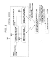
Fig. 2 is a block diagram illustrating functions with which
a portable device 201 and a living body information detecting device
205 have. The portable device 201 possesses a first identification
code associated with the user who is carrying the portable device
201. A detecting device identifying means 204 identifies the living
body information detecting device that is currently used, by
performing radio communication with the living body information
detecting device 205. An identification code generating means 202
generates the second identification code based on information from
the detecting device identifying means 204. An identification code
transmitting means 203 transmits the second identification code
to the living body information detecting device 205. The living
body information detecting device 205 uses the received second
identification code as its identification code and transmits it
by radio to a data collector 206 together with the detected living
body information data.
-
Fig. 3 shows the hardware configuration of a controller of
each of bed-type and toilet-type living body information detecting
devices. The respective controllers of the bed-type and toilet-type
living body information detecting devices are of the same hardware
configuration except for sensors that detect living body
information.
-
A pulse sensor 301 detects the pulse of a user who is lying
down in the bed when implemented as a bed-type device, and detects
the pulse of a user who is sitting on the toilet stool when implemented
as a toilet-type device. A signal detected by the pulse sensor 301
is converted into digital numerical data in a pulse sensor processing
circuit 302, read by a CPU 307, and temporarily stored in a RAM
309.
-
Further, a living body information sensor 303, which
collectively represents other living body information sensors,
detects living body information of a user who is lying down in the
bed when implemented as a bed-type device, and detects living body
information of a user who is sitting on the toilet stool when
implemented as a toilet-type device. A signal detected by the living
body information sensor 303 is converted into digital numerical
data in a living body information sensor processing circuit 304
and read by the CPU 307. Multiple kinds of sensors are mounted as
the living body information detecting sensors; a respiration sensor,
a body temperature sensor, and the like are mounted in the case
of a bed-type device, and a body temperature sensor, a urine sugar
sensor, and the like are mounted in the case of a toilet-type device.
-
A timer 310 can have its time set and read by the CPU 307.
-
The CPU 307 controls the whole living body information
detecting device in accordance with software stored in a ROM 308.
The CPU 307 reads out living body information from the sensors at
a fixed time interval, and temporarily stores the data thus obtained
in the RAM 309 together with the reading-out time. In addition,
the CPU 307 transfers by radio to the data collector the living
body information data read out by the living body information sensor
and temporarily stored in the RAM 309, by using a radio
transmitter/receiver 305 and an antenna 306, or receives the second
identification code from the above-mentioned portable device.
-
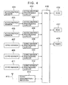
Fig. 4 shows the hardware configuration of a control portion
of the behavior monitor in the living body information detecting
device.
-
The behavior monitor is a device that is worn on a user to
detect the behaviors of the user by detecting an acceleration, an
angular velocity, etc.
-
Three acceleration sensors 401, 403, and 405 are used to detect
the accelerations in three axial directions of the user. Signals
detected by the three acceleration sensors 401, 403, and 405 are
each converted into digital numerical data in acceleration
processing circuits 402, 404, and 406, respectively, to be read
by a CPU 415 and temporarily stored in a RAM 417.
-
Further, three gyro sensors 407, 409, and 411 are used to detect
the angular speeds in three axial directions of the user. Signals
detectedby the three gyro sensors 407, 409, and 411 are each converted
into digital numerical data in gyro sensor processing circuits 408,
410, and 412, respectively, to be read by the CPU 415 and temporarily
stored in the RAM 417.
-
While acceleration sensors and gyro sensors are used as the
sensors in this example, a GPS and the like may be used as the sensors
other than those.
-
A timer 418 can have its time set and read by the CPU 415.
-
The CPU 415 controls the whole behavior sensor in accordance
with software stored in a ROM 416. The CPU 415 reads out living
body information from the respective sensors at a fixed time interval,
and temporarily stores the data thus obtained in the RAM 417 together
with the reading-out time. In addition, the CPU 415 transfers by
radio to the data collector the living body information data read
out by the respective sensors and temporarily stored in the RAM
417, by using a radio transmitter/receiver 414 and an antenna 413,
or receives the second identification code from the above-mentioned
portable device.
-
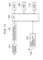
Fig. 17 shows the hardware configuration of a control portion
of the glucose monitor in the living body information detecting
device.
-
A glucose sensor 1701 detects glucose in the blood sucked in
by using a blood-sucking needle. The glucose sensor detects glucose
concentration by utilizing the fact that when a voltage is applied
to blood that has been treated in a prescribed manner, the value
of a current flowing in the blood is proportional to glucose
concentration. Of course, the method of detecting glucose
concentration is not limited to this.
-
A signal detected by the glucose sensor is converted into
digital numerical data in a glucose sensor processing circuit 1702,
read by a CPU 1707, and temporarily stored in a RAM 1709.
-
A timer 1710 can have its time set and read out by the CPU
1707.
-
The CPU 1707 controls the glucose monitor in accordance with
software stored in a ROM 1708. The CPU 1707 temporarily stores in
the RAM 1709 the time at which the glucose in blood was detected,
together with living body information data. In addition, the CPU
1707 transfers by radio to the data collector the living body
information data read out by the glucose sensor and temporarily
stored in the RAM 1709, by using a radio transmitter/receiver 1705
and an antenna 1706, or receives the second identification code
from the above-mentioned portable device.
-
Fig. 5 shows the hardware configuration of the data collector.
The data collector is controlled by a CPU 501 operating in accordance
with a program stored in a ROM 504. By using a radio
transmitter/receiver 502 and an antenna 503, the CPU 501 transmits
instruction commands to the living body information detecting device
or receives data sent from the living body information detecting
device. Data received from the living body information detecting
device is temporarily stored in a memory 505 before being stored
into a storage device 506. A hard disk or the like is used as the
storage device 506.
-
The data collector includes an external line interface 508
and connects to an external line 509, for transmitting collected
data to the external. Examples of the external line include a LAN
and a public line, and the data collector connects to a central
server 510 via those lines.
-
The central server combines living body information data from
the data collector to perform various analyses or to provide services
for external use.
-
Fig. 6 is a view showing the packet structure of data transmitted
by radio to the data collector from the living body information
detecting device.
-
A packet consists of a transmission destination identifying
code 601, a transmission originator identifying code 602, living
body information data 603, and an FCS 604.
-
The transmission destination identifying code 601 is an
identification code for identifying the data collector to which
data is transmitted. The transmission originator identifying code
602 is an identification code for identifying the living body
information detecting device from which data has been transferred.
The second identification code received from the above-mentioned
portable device is used as the transmission originator identifying
code.
-
The living body information data 603 are data sampled with
the living body information detecting device.
-
The FCS 604 is a code for detecting a packet error. As such
a code, there is used a 16-bit CRC code or the like which is calculated
using from the leading end of the packet to the end of the living
body information data 603.
-
The data collector determines, from the transmission
originator identifying code 602 contained in the packet, the living
body information detecting device from which the received data has
been transmitted, and determines whose living body information the
data is.
First embodiment
-
Fig. 7 shows the hardware configuration of the portable device
mentioned above according to a first embodiment of the present
invention.
-
A CPU 704 controls the whole portable device in accordance
with software stored in a ROM 705. The detecting device identifying
means for identifying the living body information detecting device
currently used by the user and the identification code generating
means for generating the second identification code for
discriminating among the living body information detecting devices
are also realizedby the above software. Thus, the operations carried
out by the detecting device identifying means and the identification
code generating means are operations executed by the CPU 704.
-
A radio transmitter/receiver 702 transmits/receives a message
to/from the living body information detecting device existing in
the periphery thereof via an antenna 703.
-
A radio field intensity detecting circuit 701 measures the
intensity of radio waves transmitted from the living body information
detecting device existing in the periphery thereof. The living body
information detecting device that is currently used is identified
from the results of this radio field intensity measurement.
-
A RAM 706 is used for temporary storage, etc. to store the
intensity of the radio waves from the living body information
detecting device existing in the periphery thereof.
-
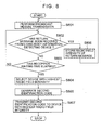
Fig. 8 is a flowchart showing operations of the detecting device
identifying means for identifying the living body information
detecting device currently used by means of the radio field intensity
detecting circuit 701, in the portable device configured as shown
in Fig. 7. The operations of the detecting device identifying means
are executed by the CPU 704.
-
In step S801, the detecting device identifying means transmits
a message by radio (through broadcast communication) to all the
living body information detecting devices existing in the periphery
thereof. The message is one requesting each living body information
detecting device to return a message, and a code of several bytes
or the like is used as its data format. The message returned by
each living body information detecting device contains information
on the kind and the like of the living body information detecting
device.
-
In step S802, the detecting device identifying means makes
a judgement as to whether it has successfully received the return
message from each living body information detecting device. Then,
just as it has received the return message, the detecting device
identifying means detects the radio field intensity of the return
message by the radio field intensity detecting circuit (701 in Fig.
7) . Ifthereturnmessagehasbeensuccessfullyreceived, theprocess
advances to step S806 where the field intensity of the return message
is stored in the RAM (706 in Fig. 7).
-
In the case where multiple living body information detecting
devices are present in the periphery thereof, the detecting device
identifying means receives multiple return messages. Accordingly,
in step S803, the detecting device identifying means continues the
reception of the return messages from the living body information
detecting devices until a preset reception waiting time elapses.
-
If it is judged in step S803 that the preset reception waiting
time has elapsed, the process advances to step S804 where the detecting
device identifying means identifies as the currently used device
the living information detecting device that has returned the message
with the highest radio field intensity from among the radio field
intensities of the return messages stored in step S806.
-
The operations of the detecting device identifying means
executed by the CPU 704 are now complete. In the next step S805,
the CPU 704 causes the identification code generating means to
generate an identification code (second identification code) for
the living body information detecting device identified-in step
S804. Operations of the identification code generating means are
described with reference to Fig. 9. In step S807, the second
identification code generated in step S805 is transmitted to the
living body information detecting device identified in step S804.
-
Fig. 9 is a flowchart showing operations performed by the
second-identification-code generating means in step S805 of Fig.
8. The operations of the identification code generating means are
executed by the CPU 704.
-
In step S901, the identification code generating means judges
whether the living body information detecting device to which the
second identification code is to be sent is the bed-type device.
Since the return message received from the living body information
detecting device in step S802 of Fig. 8 contains data for identifying
the kind of the living body information detecting device, the above
judgment is made by using this data.
-
If it is judged in step S901 that the living body information
detecting device is the bed-type device, the process advances to
step S904 where a code obtained by attaching the character "B",
for example, to the identification code (first identification code)
of the portable device is designated as the identification code
(second identification code) of the bed-type livingbody information
detecting device. For instance, when the identification code (first
identification code) of the portable device is "1234", "1234B" is
the identification code (second identification code) of the bed-type
living body information detecting device.
-
In step S902, the identification code generating means judges
whether the living body information detecting device to which the
second identification code is to be sent is the behavior monitor.
Since the return message received from the living body information
detecting device in step S802 of Fig. 8 contains data for identifying
the kind of the living body information detecting device, the above
judgment is made by using this data.
-
If it is judged in step S902 that the living body information
detecting device is the behavior monitor, the process advances to
step S905 where a code obtained by attaching the character "M",
for example, to the identification code (first identification code)
of the portable device is designated as the identification code
(second identification code) of the behavior monitor. For instance,
when the identification code (first identification code) of the
portable device is "1234", "1234M" is the identification code (second
identification code) of the behavior monitor.
-
In step S903, the identification code generating means judges
whether the living body information detecting device to which the
second identification code is to be sent is the toilet-type device.
Since the return message received from the living body information
detecting device in step S802 of Fig. 8 contains data for identifying
the kind of the living body information detecting device, the above
judgment is made by using this data.
-
If it is judged in step S903 that the living body information
detecting device is the toilet-type device, the process advances
to step S906 where a code obtained by attaching the character "T",
for example, to the identification code (first identification code)
of the associated portable device is designated as the identification
code (second identification code) of the toilet-type living body
information detecting device. For instance, when the
identification code (first identification code) of the portable
device is "1234", "1234T" is the identification code (second
identification code) of the toilet-type living body information
detecting device.
-
Fig. 10 is a flowchart illustrating operations of the living
body information detecting device corresponding to the operations
of the detecting device identifying means.
-
In step S1001, the living body information detecting device
judges whether a message from the portable device has been received.
This message is the one transmitted by the portable device in step
801 of Fig. 8. If the message has been received, in step S1002,
the living body information detecting device transmits a return
message to the portable device from which the message has been
transmitted. The return message contains data indicative of the
kind of the living body information detecting device. The portable
device receives the return message, and the radio field intensity
of the return message is measured and stored (step S806 of Fig.
8) .
-
Of the living body information detecting devices present in
the periphery thereof, the portable device transmits to the living
body information detecting device having the highest radio field
intensity the identification code (second identification code) of
that living body information detecting device. Thus, the living
body information detecting device makes a judgment in step S1003
whether it has successfully received the second identification code.
If the second identification code has not been successfully received,
the process returns to step S1001 where the living body information
detecting device again waits for reception of a message from the
portable device. If the second identification code has been
successfully received, the living body information detecting device
designates the identification code as an identification code that
the living body information detecting device will use from then
on.
-
In step S1004, the living body information detecting device
judges whether living body information can be detected from the
living body information sensors. If the living body information
cannot be detected, the living body information detecting device
judges that the living body information detecting device is not
actually used at present by the user, and the process returns to
step S1001 where the living body information detecting device again
waits for message from the portable device.
-
If the living body information can be detected in step S1004,
in step S1005, the living body information detecting device reads
out the living body information from the living body information
sensors. Then in step S1006, the second identification code received
in step S1003 is attached to the living body information data and
the resultant data is transmitted by radio to the data collector.
-
In step 51007, the living body information detecting device
is held inwaiting for a fixed period of time. Thereafter, the process
returns to step 51004 where the living body information detecting
device again repeats the reading out of the living body information
data. The fixed period of time during which the living body
information detecting device is held in waiting in step S1007
represents the interval for reading out the living body information
data from the living body-information sensors.
Second embodiment
-
Fig. 11 shows the hardware configuration of the portable device
according to a second embodiment of the present invention.
-
A CPU 1105 controls the whole portable device in accordance
with software stored in a ROM 1106. The detecting device identifying
means for identifying the living body information detecting device
currently used by the user and the identification code generating
means for generating the second identification code for
discriminating among the living body information detecting devices
are also realizedby the above software. Thus, the operations carried
out by the detecting device identifying means and the identification
code generating means are operations executed by the CPU 1105.
-
A RAM 1107 is used to store control data for the CPU 1105.
A radio transmitter/receiver 1103 transmits/receives
messages to/from the living body information detecting devices
existing in the periphery thereof via an antenna 1104.
-
A transmission power adjusting circuit 1102 changes the
transmission power of the radio transmitter/receiver 1103 upon
command from the CPU 1105.
-
A reception sensitivity adjusting circuit 1101 changes the
reception sensitivity of the radio transmitter/receiver 1103 upon
command from the CPU 1105.
-
The CPU 1105 changes the transmission power and reception
sensitivity of the radio transmitter/receiver 1103 by using the
transmission power adjusting circuit 1102 and the reception
sensitivity adjusting circuit 1101, respectively, to identify the
living body information detecting device currently used.
-
Fig. 12 is a flowchart illustrating operations of the detecting
device identifying means for identifying the living body information
detecting device currently used, in the portable device configured
as shown in Fig. 11. The operations of the detecting device
identifying means are executed by the CPU 1105.
-
In step S1201, the detecting device identifying means sets
the transmission power to a value reduced by a preset value A. In
step S1202, the detecting device identifyingmeans sets the reception
sensitivity to a value reduced by a preset value B.
-
In step S1203, the detectingdevice identifyingmeans transmits
a message by radio (through broadcast communication) to all the
living body information detecting devices existing in the periphery
thereof. The message is one requesting each living body information
detecting device to return a message, and a code of several bytes
or the like is used as its data format. The message returned by
each living body information detecting device contains information
on the kind and the like of the living body information detecting
device.
-
In step 1204, the detecting device identifying means receives
the return message from the living body information detecting device.
-
In step S1205, the detecting device identifying means judges
whether it has successfully received the message from the living
body information detecting device. If the message has not been
successfully received in step S1205, the detecting device
identifying means judges that the transmission power and the
reception sensitivity are too low, and hence sets the transmission
power to a value increased by a preset value C and sets the reception
sensitivity to a value increased by a preset value D, respectively
in steps S1206 and S1207. Then the process advances to step S1203
where transmission of the message is performed again.
-
If the return message from the living body information
detecting device has been successfully received in step 51205, the
process advances to step 51208 where the detecting device identifying
means judges whether the number of the living body information
detecting devices from which it has successfully received the return
message is one. If it is judged in step S1208 that there are more
than one living body information detecting devices from which it
has successfully received the return message, the process returns
to step S1201, and after making the transmission power and the
reception sensitivity lower in steps S1201 and 51202, respectively,
the detecting device identifying means again transmits a message
to the living body information detecting devices present in the
periphery thereof in step S1203.
-
If it is judged in step S1208 that the number of the living
body information detecting devices from which the message has been
successfully received is one, this may be regarded as indicating
that the nearest of the living body information detecting devices
has been detected. The detecting device identifying means
identifies that living body information detecting device as the
living body information detecting device that is currently used
by the user.
-
The operations of the detecting device identifying means
executed by the CPU 1105 are now complete. In the next step 51209,
the CPU 1105 causes the identification code generating means to
generate an identification code (second identification code) for
the identified living body information detecting device. Then in
step S1210, the CPU 1105 transmits the second identification code
generated in step S1209 to the identified living body information
detecting device. The operations of the identification code
generating means are the same as those of Fig. 9.
-
In this embodiment, the operations performed by the living
body information detecting device are the same as those shown in
the flowchart of Fig. 10.
Third embodiment
-
Fig. 13 shows the hardware configuration of the portable device
according to a third embodiment of the present invention.
-
The portable device of this embodiment has a function of
detecting living body information. Herein, the description is
directed to a case where a pulse sensor 1301 that detects the pulse
and an acceleration sensor 1303 that detects the acceleration of
a user are used. Examples of other sensors used include those for
detecting body temperature, blood flow, and the like.
-
The pulse wave detected by the pulse sensor 1301 is converted
into digital data in apulse sensorprocessing circuit 1302. Further,
the acceleration detected by the acceleration sensor 1303 is
converted into digital data in an acceleration sensor processing
circuit 1304. Those sensor information data are temporarily stored
in a RAM 1312 by means of a program stored in a ROM 1311 and due
to control by a CPU 1310 that controls the whole portable device.
-
The CPU 1310 controls the whole portable device in accordance
with software stored in the ROM 1311.
-
By using a radio transmitter/receiver 1305 and an antenna 1306,
the CPU 1310 transmits by radio the living body information data
temporarily stored in the RAM 1312 to the data collector, exchanges
information with the living body information detecting devices
present in the periphery thereof, or transmits the second
identification code.
-
The identification code generating means for generating the
second identification code used to discriminate among the living
body information detecting devices is also realized by the software.
Thus, the operations carried out by the identification code
generating means are operations executed by the CPU 1310.
-
With a timer 1313, the current time can be called up by the
CPU 1310. When each sensor samples data, the CPU 1310 calls up the
time indicated by the timer 1313 and sets it as the sampling time.
The sampling time is stored together with the sampling data of each
sensor.
-
Fig. 14 is a flowchart illustrating operations of the portable
device in the case where the living body information detecting device
identifies the user by itself, in which the portable device generates
and transmits the second identification code.
-
In step S1401, the portable device detects living body
information with the pulse sensor, the acceleration sensor, and
the like, and in step S1402, the portable device transmits the living
body information data by radio to the data collector.
-
In step 51403, the portable device judges whether a
transmission request for the living body information data has been
made by the living body information detecting device located in
the periphery thereof. When starting detection of living body
information with its own sensor, the living body information
detecting device located in the periphery requests the portable
device located in the periphery thereof to transmit the living body
information data detected on the portable device side. The
transmission request for the living body information data mentioned
above is made for both the pulse and the acceleration or individually
for each of the pulse and acceleration.
-
If it is judged in step S1403 that there has been the transmission
request for living body information data from the living body
information detecting device present in the periphery, the process
advances to step S1404 where the portable device transmits the living
body information data to that living body information detecting
device.
-
In step S1405, the portable device judges whether the living
body information detecting device present in the periphery thereof
has made a transmission request for the identification code (second
identification code) of that living body information detecting
device. Upon finding a match between the characteristics of the
living body information data transmitted from the portable device
and those of the living body information data detected by itself,
the living body information detecting device in the periphery
requests the portable device to transmit an identification code
(second identification code) which the living body information
detecting device will use from then on.
-
If it is judged in step S1405 that there has been a transmission
request for the second identification code from the living body
information detecting device present in the periphery, the process
advances to step S1406 where the identification code generating
means operated by the CPU 1310 of the portable device generates
the identification code (second identification code) for the living
body information detecting device. Then, in step S1407, the second
identification code is transmitted to that living body information
detecting device.
-
In step S1408, the portable device judges whether a living
body information detection stop request has been made from the living
body information detecting device to which the second identification
code has been transmitted. After receiving the second
identification code from the portable device, the living body
information detecting device transmits the living body information
detection stop request by radio to the portable device to achieve
power saving for the portable device.
-
If it is judged in step S1408 that the portable device has
received the living body information detection stop request, the
power source of the sensor-related circuit is shut off to save power
consumption in step S1409.
-
In step S1410, the portable device judges whether there has
been a living body information detection start request from the
living body information detecting device. When unable to detect
living body information with its own sensors, the living body
information detecting device transmits the living body information
detection start request to the portable device. If the living body
information detection start request has been made, the portable
device turns on the power source of the sensor-related circuit in
step 51411 so that the process returns to step S1401 to start detection
of living body information again.
-
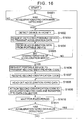
Fig. 15 is a flowchart showing operations of the bed-type or
toilet-type living body information detecting device for identifying
the user by itself and acquiring the second identification code
from the portable device owned by the user.
-
In step S1501, the living body information detecting device
judges whether its own living body information sensor has started
detection ofliving bodyinformation. If the livingbody information
sensor has started detection of living body information, in the
case of the bed-type living body information detecting device, it
is judged that the user has lain down on the bed; in the case of
the toilet-type living body information detecting device, it is
judged that the user has sat down on the toilet stool. Thus, the
process advances to step S1502 where the living body information
detecting device searches for a portable device present in the
periphery thereof. Then, the living body information detecting
device requests the portable device thus searched out in step S1503
to transmit pulse data detected by the portable device, and receives
the pulse data from the portable device in step S1504.
-
In step S1505, the living body information detecting device
judges whether there is a match between the characteristics of the
pulse data detected by the living body information detecting device
and those of the pulse data received from the portable device. In
this case, the above-mentioned match between the characteristics
of the respective pulse data is judged to have occurred when the
difference between numerical values respectively detected by the
living body information detecting device and the portable device,
the numerical values each representing the characteristics of the
pulse data, such as the pulse rate, cycle, phase, or the like, is
smaller than a predetermined value.
-
If it is judged in step S1505 that the characteristics of the
respective pulse data do not match, the process returns to step
S1502 where the living body information detecting device makes a
search for another portable device present in the periphery thereof.
-
If it is judged in step 51505 that there is a match between
the characteristics of the respective pulse data, the-process
advances to step S1506 where the living body information detecting
device requests the portable device to transmit an identification
code (second identification code) which the living body information
detecting device will use from then on.
-
In step S1507, the living body information detecting device
receives the second identification code from the portable device.
Then, in step S1508, the living body information detecting device
transmits a living body information detection stop request to the
portable device. This is performed to save power of the portable
device by detecting living body information on the bed-type device
or toilet-type device side.
-
In step S1509, the living body information detecting device
reads out living body information data from the living body
information sensors such as the pulse sensor.
-
In step S1510, the living body information detecting device
attaches the second identification code received in step S1507 to
the living body information data thus read out, and transmits the
resultant data to the data collector.
-
In step S1511, the living body information detecting device
is held in waiting for a fixed period of time. The fixed period
of time represents the sampling interval for detecting living body
information.
-
In step S1512, the living body information detecting device
checks whether it can detect living body information. If living
body information can be detected, the process returns to step S1509
where the living body information detecting device reads out living
body information data again.
-
If it is judged in step S1512 that living body information
cannot be detected, this may mean that the subject has moved away
from the bed or the toilet-type device or an abnormality has occurred.
The process advances to step S1513 in such a case.
-
In step S1513, the living body information detecting device
transmits a living body information detection start request to the
portable device.
-
In step S1514, the living body information detecting device
transmits to the portable device a transmission request for the
living body information data such as the pulse rate detected by
the portable device.
-
In step 51515, the living body information detecting device
receives the living body information data from the portable device.
-
In step S1516, the living body information detecting device
judges whether the living body information data such as pulse rate
received from the portable device is normal. If the living body
information data such as pulse rate is normal, the process advances
to step S1518 where it is judged that the user has moved away from
the bed-type device or the toilet-type device. If the living body
information data such as pulse rate is abnormal, the process advances
to step S1517 where the information on the occurrence of abnormality
is transmitted by radio to the data collector.
-
Fig. 16 is a flowchart illustrating operations of the behavior
monitor for identifying the user by itself and acquiring the second
identification code from the portable device owned by the user.
-
In step S1601, the behavior monitor judges whether the
acceleration sensor or the gyro sensor has started detection of
acceleration data or gyro data. If the detection of the acceleration
data or gyro data has been started, it is possible to judge that
the user has started using the behavior monitor. Thus, the process
advances to step S1602 where the behavior monitor searches for a
portable device present in the vicinity thereof. Then, the behavior
monitor requests the portable device thus searched out in step S1603
to transmit the acceleration data detected by the portable device,
and receives acceleration data form the portable device in step
S1604.
-
In step S1605, the behavior monitor judges whether there is
a match between the characteristics of the acceleration data detected
by the behavior monitor and those of the acceleration data received
from the portable device. In this case, the above match between
the characteristics of the respective acceleration data is judged
to have occurred when the difference between numerical values
respectively detected by the behavior monitor and the portable device,
the numerical values each representing the characteristics of the
acceleration data, such as the acceleration, cycle, phase, or the
like, is smaller than a predetermined value.
-
If it is judged in step S1605 that the characteristics of the
respective acceleration data do not match, the process returns to
step S1602 where the behavior monitor performs detection of another
portable device present in the periphery thereof.
-
If it is judged in step S1605 that a match is found between
the characteristics of the respective acceleration data, the process
advances to step S1606 where the behavior monitor requests the
portable device to transmit the second identification code.
-
In step S1607, the behavior monitor receives the second
identification code from the portable device.
-
In step S1608, the behavior monitor reads out living body
information data from the acceleration or gyro sensor.
-
In step S1609, the behavior monitor attaches the second
identification code received in step S1607 to the living body
information data thus read out, and transmits the resultant data
to the data collector.
-
In step S1610, the behavior monitor is held in waiting for
a fixed period of time. The fixed period of time represents the
sampling interval for detecting data.
-
In step 51611, the behavior monitor checks whether it can detect
the acceleration or gyro data. If the acceleration or gyro data
can be detected, the process returns to step S1608 where the behavior
monitor reads out the acceleration or gyro data again.
-
If the acceleration or gyro data cannot be read out in step
S1608, the process returns to step S1601 to wait for the detection
of the acceleration or gyro data.
-
While in the third embodiment the living body information
detecting device receives living body information data from the
portable device and compares the living body information data with
the living body information data detected by its own sensors to
thereby identify the user, the identification of the user may be
performed by the portable device. In that case, the portable device
receives living body information data from the living body
information detecting device and compares the living body
information data with the living body information data detected
by the sensors of the portable device to thereby identify the user.
-
Note that a configuration is also possible in which the program
installed in the above-described living body information detecting
device for realizing the functions performed by the CPU is stored
in a computer-readable recording medium, and the program recorded
in the recording medium is read and executed by a device equipped
with sensors and capable of reading and executing the program, thereby
using the device as the living body information detecting device
of the present invention.
-
Further, a configuration is also possible in which the program
installed in the portable device for realizing the functions
performed by the CPU is stored in a computer-readable recording
medium, and the program recorded in the recording medium is read
and executed by a device capable of reading and executing the program,
thereby using the device as the portable device of the present
invention. In this case, using a device equipped with sensors and
capable of reading and executing the program enables identification
of the user to be performed with the living body information detecting
device as in the third embodiment of the present invention.