EP1477106B1 - High temperature and pressure steam sterilization container for an endoscope and endoscope cleaning and sterilizing device - Google Patents
High temperature and pressure steam sterilization container for an endoscope and endoscope cleaning and sterilizing device Download PDFInfo
- Publication number
- EP1477106B1 EP1477106B1 EP02758873A EP02758873A EP1477106B1 EP 1477106 B1 EP1477106 B1 EP 1477106B1 EP 02758873 A EP02758873 A EP 02758873A EP 02758873 A EP02758873 A EP 02758873A EP 1477106 B1 EP1477106 B1 EP 1477106B1
- Authority
- EP
- European Patent Office
- Prior art keywords
- endoscope
- tray
- cleaning
- sterilization
- pipe line
- Prior art date
- Legal status (The legal status is an assumption and is not a legal conclusion. Google has not performed a legal analysis and makes no representation as to the accuracy of the status listed.)
- Expired - Fee Related
Links
Images


Classifications
-
- A—HUMAN NECESSITIES
- A61—MEDICAL OR VETERINARY SCIENCE; HYGIENE
- A61L—METHODS OR APPARATUS FOR STERILISING MATERIALS OR OBJECTS IN GENERAL; DISINFECTION, STERILISATION OR DEODORISATION OF AIR; CHEMICAL ASPECTS OF BANDAGES, DRESSINGS, ABSORBENT PADS OR SURGICAL ARTICLES; MATERIALS FOR BANDAGES, DRESSINGS, ABSORBENT PADS OR SURGICAL ARTICLES
- A61L2/00—Methods or apparatus for disinfecting or sterilising materials or objects other than foodstuffs or contact lenses; Accessories therefor
- A61L2/24—Apparatus using programmed or automatic operation
-
- A—HUMAN NECESSITIES
- A61—MEDICAL OR VETERINARY SCIENCE; HYGIENE
- A61B—DIAGNOSIS; SURGERY; IDENTIFICATION
- A61B1/00—Instruments for performing medical examinations of the interior of cavities or tubes of the body by visual or photographical inspection, e.g. endoscopes; Illuminating arrangements therefor
- A61B1/00142—Instruments for performing medical examinations of the interior of cavities or tubes of the body by visual or photographical inspection, e.g. endoscopes; Illuminating arrangements therefor with means for preventing contamination, e.g. by using a sanitary sheath
- A61B1/00144—Hygienic packaging
-
- A—HUMAN NECESSITIES
- A61—MEDICAL OR VETERINARY SCIENCE; HYGIENE
- A61B—DIAGNOSIS; SURGERY; IDENTIFICATION
- A61B1/00—Instruments for performing medical examinations of the interior of cavities or tubes of the body by visual or photographical inspection, e.g. endoscopes; Illuminating arrangements therefor
- A61B1/12—Instruments for performing medical examinations of the interior of cavities or tubes of the body by visual or photographical inspection, e.g. endoscopes; Illuminating arrangements therefor with cooling or rinsing arrangements
- A61B1/121—Instruments for performing medical examinations of the interior of cavities or tubes of the body by visual or photographical inspection, e.g. endoscopes; Illuminating arrangements therefor with cooling or rinsing arrangements provided with means for cleaning post-use
- A61B1/123—Instruments for performing medical examinations of the interior of cavities or tubes of the body by visual or photographical inspection, e.g. endoscopes; Illuminating arrangements therefor with cooling or rinsing arrangements provided with means for cleaning post-use using washing machines
-
- A—HUMAN NECESSITIES
- A61—MEDICAL OR VETERINARY SCIENCE; HYGIENE
- A61B—DIAGNOSIS; SURGERY; IDENTIFICATION
- A61B1/00—Instruments for performing medical examinations of the interior of cavities or tubes of the body by visual or photographical inspection, e.g. endoscopes; Illuminating arrangements therefor
- A61B1/12—Instruments for performing medical examinations of the interior of cavities or tubes of the body by visual or photographical inspection, e.g. endoscopes; Illuminating arrangements therefor with cooling or rinsing arrangements
- A61B1/121—Instruments for performing medical examinations of the interior of cavities or tubes of the body by visual or photographical inspection, e.g. endoscopes; Illuminating arrangements therefor with cooling or rinsing arrangements provided with means for cleaning post-use
- A61B1/125—Instruments for performing medical examinations of the interior of cavities or tubes of the body by visual or photographical inspection, e.g. endoscopes; Illuminating arrangements therefor with cooling or rinsing arrangements provided with means for cleaning post-use using fluid circuits
-
- A—HUMAN NECESSITIES
- A61—MEDICAL OR VETERINARY SCIENCE; HYGIENE
- A61L—METHODS OR APPARATUS FOR STERILISING MATERIALS OR OBJECTS IN GENERAL; DISINFECTION, STERILISATION OR DEODORISATION OF AIR; CHEMICAL ASPECTS OF BANDAGES, DRESSINGS, ABSORBENT PADS OR SURGICAL ARTICLES; MATERIALS FOR BANDAGES, DRESSINGS, ABSORBENT PADS OR SURGICAL ARTICLES
- A61L2/00—Methods or apparatus for disinfecting or sterilising materials or objects other than foodstuffs or contact lenses; Accessories therefor
- A61L2/02—Methods or apparatus for disinfecting or sterilising materials or objects other than foodstuffs or contact lenses; Accessories therefor using physical phenomena
- A61L2/04—Heat
- A61L2/06—Hot gas
- A61L2/07—Steam
-
- A—HUMAN NECESSITIES
- A61—MEDICAL OR VETERINARY SCIENCE; HYGIENE
- A61L—METHODS OR APPARATUS FOR STERILISING MATERIALS OR OBJECTS IN GENERAL; DISINFECTION, STERILISATION OR DEODORISATION OF AIR; CHEMICAL ASPECTS OF BANDAGES, DRESSINGS, ABSORBENT PADS OR SURGICAL ARTICLES; MATERIALS FOR BANDAGES, DRESSINGS, ABSORBENT PADS OR SURGICAL ARTICLES
- A61L2/00—Methods or apparatus for disinfecting or sterilising materials or objects other than foodstuffs or contact lenses; Accessories therefor
- A61L2/16—Methods or apparatus for disinfecting or sterilising materials or objects other than foodstuffs or contact lenses; Accessories therefor using chemical substances
- A61L2/18—Liquid substances or solutions comprising solids or dissolved gases
-
- A—HUMAN NECESSITIES
- A61—MEDICAL OR VETERINARY SCIENCE; HYGIENE
- A61L—METHODS OR APPARATUS FOR STERILISING MATERIALS OR OBJECTS IN GENERAL; DISINFECTION, STERILISATION OR DEODORISATION OF AIR; CHEMICAL ASPECTS OF BANDAGES, DRESSINGS, ABSORBENT PADS OR SURGICAL ARTICLES; MATERIALS FOR BANDAGES, DRESSINGS, ABSORBENT PADS OR SURGICAL ARTICLES
- A61L2/00—Methods or apparatus for disinfecting or sterilising materials or objects other than foodstuffs or contact lenses; Accessories therefor
- A61L2/26—Accessories or devices or components used for biocidal treatment
-
- A—HUMAN NECESSITIES
- A61—MEDICAL OR VETERINARY SCIENCE; HYGIENE
- A61B—DIAGNOSIS; SURGERY; IDENTIFICATION
- A61B90/00—Instruments, implements or accessories specially adapted for surgery or diagnosis and not covered by any of the groups A61B1/00 - A61B50/00, e.g. for luxation treatment or for protecting wound edges
- A61B90/70—Cleaning devices specially adapted for surgical instruments
- A61B2090/701—Cleaning devices specially adapted for surgical instruments for flexible tubular instruments, e.g. endoscopes
-
- A—HUMAN NECESSITIES
- A61—MEDICAL OR VETERINARY SCIENCE; HYGIENE
- A61L—METHODS OR APPARATUS FOR STERILISING MATERIALS OR OBJECTS IN GENERAL; DISINFECTION, STERILISATION OR DEODORISATION OF AIR; CHEMICAL ASPECTS OF BANDAGES, DRESSINGS, ABSORBENT PADS OR SURGICAL ARTICLES; MATERIALS FOR BANDAGES, DRESSINGS, ABSORBENT PADS OR SURGICAL ARTICLES
- A61L2202/00—Aspects relating to methods or apparatus for disinfecting or sterilising materials or objects
- A61L2202/10—Apparatus features
- A61L2202/12—Apparatus for isolating biocidal substances from the environment
- A61L2202/122—Chambers for sterilisation
-
- A—HUMAN NECESSITIES
- A61—MEDICAL OR VETERINARY SCIENCE; HYGIENE
- A61L—METHODS OR APPARATUS FOR STERILISING MATERIALS OR OBJECTS IN GENERAL; DISINFECTION, STERILISATION OR DEODORISATION OF AIR; CHEMICAL ASPECTS OF BANDAGES, DRESSINGS, ABSORBENT PADS OR SURGICAL ARTICLES; MATERIALS FOR BANDAGES, DRESSINGS, ABSORBENT PADS OR SURGICAL ARTICLES
- A61L2202/00—Aspects relating to methods or apparatus for disinfecting or sterilising materials or objects
- A61L2202/10—Apparatus features
- A61L2202/17—Combination with washing or cleaning means
-
- A—HUMAN NECESSITIES
- A61—MEDICAL OR VETERINARY SCIENCE; HYGIENE
- A61L—METHODS OR APPARATUS FOR STERILISING MATERIALS OR OBJECTS IN GENERAL; DISINFECTION, STERILISATION OR DEODORISATION OF AIR; CHEMICAL ASPECTS OF BANDAGES, DRESSINGS, ABSORBENT PADS OR SURGICAL ARTICLES; MATERIALS FOR BANDAGES, DRESSINGS, ABSORBENT PADS OR SURGICAL ARTICLES
- A61L2202/00—Aspects relating to methods or apparatus for disinfecting or sterilising materials or objects
- A61L2202/20—Targets to be treated
- A61L2202/24—Medical instruments, e.g. endoscopes, catheters, sharps
Definitions
- the present invention relates to a high temperature and pressure steam sterilization container for an endoscope, and an endoscope cleaning and sterilizing device in which autoclave sterilization (high temperature and pressure steam sterilization) is performed.
- an endoscope has been broadly used in a medical field.
- an elongated insertion portion is inserted into a body cavity.> Accordingly, a deep part or the like in the body cavity is observed. Furthermore, when a treatment tool is used as required, a medical treatment and the like can be carried out. It is indispensable to securely disinfect and sterilize these endoscopes for medicine after use.
- autoclave sterilization high temperature and pressure steam sterilization
- the above-described autoclave sterilization does not involve any laborious operation in a sterilization treatment.
- the treated endoscope apparatuses can be used immediately after the sterilization treatment, and additionally a running cost is low.
- an autoclave sterilization device is described in Jpn. Pat. Appln. KOKAI Publication No. JP 5-285103 .
- the device is described in which the endoscope capable of performing high temperature and pressure steam sterilization is projected to perform the autoclave sterilization (high temperature and pressure steam sterilization).
- the above-described environmental condition of the autoclave sterilization is very severe for an electronic endoscope which is a precision electronic apparatus including image pickup devices such as CCD.
- an electronic endoscope which has resistance to the condition and which is capable of performing the autoclave sterilization (high temperature and pressure steam sterilization)
- various measures have to be taken such as a high-pressure measure, a high-temperature measure, and a steam measure.
- An elongated flexible tubular portion is disposed behind a tip hard portion disposed in a tip of the endoscope insertion portion. Moreover, the flexible tubular portion tends to be easily affected by high pressure, high temperature, or steam as compared with the tip hard portion, and a further advanced measure is required.
- the endoscope not only the endoscope but also the other peripherals of the endoscope are disposed together in a tray and projected into an autoclave sterilization device.
- the peripherals of the endoscope to be projected into the autoclave sterilization device include various buttons for feeding air or water and the like, detached from the endoscope, a water proof cap to be attached to the endoscope, and treatment tools such as forceps.
- the measure against the high pressure, high temperature, or steam is required to be taken in the constitution of the endoscope insertion portion itself as described above at the time of the autoclave sterilization treatment. Furthermore, in addition to this measure, it is also important to devise a projection mode of an object to be sterilized/treated during the projection into the autoclave sterilization device, so that the endoscope insertion portion is prevented from being damaged by the peripherals of the endoscope.
- a capacity of a sterilization treatment chamber is comparatively small in the conventional autoclave sterilization device having such a size that the device can be disposed in an endoscopic inspection chamber. Therefore, when the endoscope including the elongated soft insertion portion is projected into the sterilization treatment chamber, the insertion portion needs to be bundled in a round shape and projected.
- the endoscope needs to be cleaned before the autoclave sterilization treatment. At this time, to clean the endoscope in an automatic cleaner, the endoscope has to be stored in a predetermined mode also in the cleaner.
- a user stores and cleans the endoscope in the predetermined mode in the cleaner. Thereafter, the endoscope is taken out of the cleaner, and set in the tray (or container) for the autoclave sterilization treatment. Also at this time, an operation for storing the endoscope in the predetermined mode in the tray (or container) for the autoclave sterilization treatment needs to be performed, and therefore the operation of the autoclave sterilization treatment becomes laborious.
- the present invention has been developed in consideration of these circumstances, and an object thereof is to provide a high temperature and pressure steam sterilization container for an endoscope, and an endoscope cleaning and sterilizing device in which an operation is facilitated in a case where a high temperature and pressure steam sterilization treatment is performed after cleaning the endoscope used in an endoscopic inspection.
- another object of the present invention is to provide an endoscope cleaning and sterilizing device whose entire cost is reduced and which is entirely miniaturized so that the endoscope cleaning and sterilizing device can be disposed even in a general consultation room where diagnosis by the endoscope is conducted and which is capable of reducing a time required for operations of cleaning, disinfecting, and sterilizing the endoscope or the like, performed between cases of endoscopic diagnosis and which is capable of enhancing efficiency of the endoscopic diagnosis.
- Another object is to provide an endoscope cleaning and sterilizing device capable of easily maintaining a sterilized state of an endoscope subjected to the respective cleaning, disinfecting, and sterilizing operations.
- the document JP 2002 045335 A discloses an endoscope cleaning and sterilizing device comprising a container, a cleaning section and a high temperature and pressure steam sterilization section.
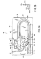
- FIG. 1 is a schematic constitution diagram of a whole endoscope device including a first embodiment of the present invention
- FIG. 2 is an outline view of an endoscope cleaning and sterilizing system of the present embodiment.
- an endoscope device 1 including the first embodiment of the present invention is mainly constituted of an endoscope 2, a light source device 3, a video processor 5, and a monitor 6.
- the endoscope 2 includes image pickup means (not shown).
- the light source device 3 is detachably attached to the endoscope 2 to supply an illuminative light to a light guide disposed in the endoscope 2.
- the video processor 5 is connected to the endoscope 2 via a signal cable 4 to control the image pickup means of the endoscope 2, and further processes a signal obtained from the image pickup means to output a standard video signal.
- the monitor 6 inputs the video signal from the video processor 5 to display an endoscope image.
- the endoscope 2 is constituted to be cleaned after used in observation or treatment, and can further be sterilized in autoclave sterilization (high temperature and pressure steam sterilization) after cleaned.
- the endoscope 2 is provided with an elongated insertion portion 7 having flexibility.
- An operation portion 8 is disposed on a base-end side of the insertion portion 7. Furthermore, a side portion of the operation portion 8 is connected to one end of a universal cord 9 having flexibility.
- a connector portion 10 is disposed on the other end of the universal cord 9. This connector portion 10 is detachably connectable to the light source device 3.
- An electric connector portion 11 is disposed on the side portion of this connector portion 10. This electric connector portion 11 is detachably connectable to one end of the signal cable 4. The other end of the signal cable 4 is connectable to the video processor 5.
- the electric connector portion 11 is provided with a ventilation portion (not shown) which connects the inside of the endoscope 2 to the outside.
- An insertion portion side bend preventive member 12 is disposed in a connecting portion between the insertion portion 7 and the operation portion 8.
- This bend preventive member 12 includes an elastic member which prevents a rapid bend of the connecting portion between the insertion portion 7 and the operation portion 8.
- an operation portion side bend preventive member 13 is disposed in the connecting portion between the operation portion 8 and the universal cord 9.
- a connector portion side bend preventive member 14 is disposed in the connecting portion between the universal cord 9 and the connector portion 10.
- the insertion portion 7 is constituted of an elongated flexible tubular portion 15, a curved portion 16, and a tip portion 17.
- the flexible tubular portion 15 is a soft portion having the flexibility.
- the curved portion 16 is disposed on the tip side of the flexible tubular portion 15. The curved portion 16 can be curved by a remote operation from the operation portion 8.
- the tip portion 17 is disposed on the tip of the curved portion 16, and is provided with an optical observation system, an optical illuminating system, a solution feeding port and air or water feeding nozzle, a suction port and the like.
- a pipe line for air or water feed, or a treatment tool passing channel which also serves as a suction pipe line and the like are disposed in the insertion portion 7.
- the tip of the pipe line for air or water feed is connected to a solution feeding port and air or water feeding nozzle of the tip portion 17.
- the tips of the suction pipe line and treatment tool passing channel are connected to the suction port.
- the operation portion 8 is provided with an air or water feed operation button 21, a suction operation button 22, two curving operation knob 23, a plurality of remote switches 24, and a treatment tool insertion port 25.
- the air or water feed operation button 21 switches and operates the air or water feed in the pipe line for air or water feed in the insertion portion 7.
- the suction operation button 22 switches and operates a suction operation from a suction pipe line.
- Two curving operation knobs 23 are coaxially disposed in two upper and lower stages. Moreover, one curving operation knob 23 curves and operates the curved portion 16, for example, in a vertical direction. The other curving operation knob 23 curves and operates the curved portion 16, for example, in a right or left direction.
- the plurality of remote switches 24 remotely operate the video processor 5.
- the treatment tool insertion port 25 is an opening communicating with the base end of the treatment tool passing channel.
- a cleaning solution or gas is spouted toward an observation window of the optical observation system (not shown) from the solution feeding port and air or water feeding nozzle (not shown) of the tip portion 17 by the switching operation of the air or water feeding by the air or water feeding operation button 21.
- a solution in a body cavity is sucked from the suction port (not shown) of the tip portion 17 by the operation of the suction operation button 22.
- a treatment tool is passed through the treatment tool passing channel (not shown) disposed in the insertion portion 7 from the treatment tool insertion port 25 of the operation portion 8.
- this treatment tool is extended to the outside of the channel from the suction port (not shown) of the tip portion 17 which is the opening on the tip side of the treatment tool passing channel.
- the connector portion 10 is further provided with a gas supply cap 26, a water feeding tank pressurizing cap 28 and solution supply cap 29, a suction cap 30, and an injection cap 31.
- the gas supply cap 26 is detachably connected to a gas supply source (not shown) built in the light source device 3.
- the water feed tank pressurizing cap 28 and solution supply cap 29 are detachably connected to a water feed tank 27 which is a solution supply source.
- the suction cap 30 is connected to a suction source (not shown). Moreover, a suction force from the suction source is exerted onto the suction port of the tip portion 17 via the suction cap 30 and suction pipe line to perform the suction via the suction port of the tip portion 17.
- the injection cap 31 is connected to water feeding means (not shown). Moreover, water is fed via the solution feeding port of the tip portion 17 via the injection cap 31 and the pipe line for air or water feeding from the water feeding means.
- the connector portion 10 is further provided with an earth terminal cap 32.
- the earth terminal cap 32 returns a leak current to a high frequency treatment device in a case where a high frequency leak current is generated in the endoscope during a high frequency treatment.
- a regulating portion (not shown) is formed in accordance with the shape of the endoscope 2 in the connector portion 10.
- the regulating portion is formed in such a manner that the respective portions of the endoscope 2 are stored in predetermined positions.
- the regulating portion is provided with an insertion portion regulating portion (not shown) in which the insertion portion 7 is stored.
- the electric connector portion 11 is detachably connectable to a waterproof cap provided with a pressure adjustment valve (hereinafter referred to as the waterproof cap) 33.
- This waterproof cap 33 is provided with the pressure adjustment valve (not shown).
- a container case for sterilization 34 which stores the endoscope 2 is used.
- the container case 34 is constituted of a tray 35 which is a high temperature and pressure steam sterilization container for the endoscope, and a back lid member 36.
- a containing concave portion which stores the endoscope insertion portion as described later is formed in the tray 35.
- a plurality of ventilation ports are disposed in these tray 35 and back lid member 36. Moreover, vapor is capable of passing in the container case 34 through these ventilation ports at the time of the autoclave sterilization (high temperature and pressure steam sterilization).
- a temperature condition of the sterilization process of the autoclave sterilization differs with a type of an autoclave sterilization device (not shown) or a time of the sterilization process.
- the temperature condition is set in a range of about 115°C to 138°C.
- the condition can be set to about 142°C in some of the sterilization devices.
- a time condition differs with the temperature condition of the sterilization process.
- the condition is set to about 3 to 60 minutes.
- the condition may also be set to about 100 minutes depending on the type of the sterilization device.
- the pressure in a sterilization chamber in this process is set to about +0.2 MPa with respect to an atmospheric pressure.
- the autoclave sterilization (high temperature and pressure steam sterilization) process of the general pre-vacuum type includes a pre-vacuum process and a sterilization process.
- the pre-vacuum process the inside of the sterilization chamber in which a sterilization object apparatus is stored is brought into a reduced pressure state before the sterilization process.
- a high pressure and temperature steam is fed into the sterilization chamber to perform the sterilization after the pre-vacuum process.
- the pressure in the sterilization chamber in the pre-vacuum process is generally set to about -0.07 MPa to 0.09 MPa with respect to an atmospheric pressure.
- a drying process is sometimes included after the sterilization process.
- the inside of the sterilization chamber is brought into the reduced pressure state again after the sterilization process. Accordingly, the sterilization object apparatus after the sterilization is dried.
- the pressure inside the sterilization chamber is reduced to discharge steam from the sterilization chamber, and the drying of the sterilization object apparatus in the sterilization chamber is promoted.
- the pressure in the sterilization chamber in this process is generally set to about -0.07 MPa to 0.09 MPa with respect to the atmospheric pressure.
- the waterproof cap 33 is attached to the electric connector portion 11. At this time, the pressure adjustment valve (not shown) of the waterproof cap 33 is closed. Moreover, in this state, the ventilation port of the electric connector portion 11 is blocked by the waterproof cap 33, and the inside of the endoscope 2 is sealed and closed from the outside in a watertight manner.
- the pressure in the sterilization chamber decreases and a pressure difference is made such that the pressure of the outside of the endoscope 2 is lower than that of the inside.
- the pressure adjustment valve of the waterproof cap 33 opens by the pressure difference at this time. Therefore, the inside of the endoscope 2 communicates with the outside via the ventilation port of the electric connector portion 11. Accordingly, a large difference is prevented from being made between the pressure inside the endoscope 2 and that in the sterilization chamber. As a result, the endoscope 2 does not break by the pressure difference between the inside and the outside.
- the sterilization chamber is pressurized.
- the pressure adjustment valve of the waterproof cap 33 closes. Accordingly, the high pressure and temperature steam does not positively enter the endoscope 2 via the waterproof cap 33 and the ventilation port of the electric connector portion 11.
- an outer shell of the flexible tubular portion 15 is formed of a macromolecular material.
- the connecting portion of an exterior member of the endoscope 2 is provided with an O ring and the like formed of a fluorine or silicon rubber which is sealing means.
- the high temperature and pressure steam gradually enters the endoscope 2 from the outer shell of the flexible tubular portion 15 or the O ring or the like of the connecting portion of the exterior member of the endoscope 2.
- the pressure in the sterilization chamber decreases and the pressure difference is made such that the pressure of the outside of the endoscope 2 is lower than that of the inside.
- the pressure adjustment valve of the waterproof cap 33 opens substantially simultaneously with the generation of the pressure difference. Therefore, the inside of the endoscope 2 communicates with the outside via the ventilation port of the electric connector portion 11 to prevent the large difference from being made between the pressure inside the endoscope 2 and that in the sterilization chamber. Accordingly, the endoscope 2 does not break by the pressure difference between the inside and the outside.
- the pressure reducing process ends, the inside of the sterilization chamber is pressurized to make the pressure difference such that the pressure inside the endoscope 2 is higher than that of the outside, and the pressure adjustment valve then closes.
- the inside of the endoscope 2 communicates with the outside via the ventilation port of the electric connector portion 11 to bring the inside of the endoscope 2 into the atmospheric pressure. Accordingly, a load by the pressure generated in the exterior member of the endoscope 2 is eliminated.
- the endoscope 2 is stored in the tray 35 which is a container for performing the autoclave sterilization (high temperature and pressure steam sterilization) with respect to the above-described endoscope 2, and is stored in an endoscope cleaner described later in this state, so that the endoscope 2 can be cleaned.
- the endoscope cleaning and sterilizing system of the present embodiment is provided with an endoscope cleaner 40 for cleaning the endoscope 2, and an autoclave device 50 for performing the autoclave sterilization (high temperature and pressure steam sterilization) of the endoscope 2.
- the endoscope cleaner 40 is provided with a cleaning bath 41 whose upper surface is opened in an upper part of a cleaner main body 40a.
- a waterproof lid 42 is openably and closably disposed facing the cleaning bath 41 in the upper surface opening of the cleaning bath 41.
- the waterproof lid 42 is closed in a state in which the tray 35 including the endoscope 2 stored therein is stored in the cleaning bath 41, and accordingly the sealing is possible.
- a water injection port 43, a treatment channel cleaning tool 44, an air or water feeding cleaning tool 45, and a water discharge tool 46 are disposed on the side wall inside the cleaning bath 41.
- the water injection port 43 guides liquids such as the cleaning solution and water into the cleaning bath 41.
- the treatment channel cleaning tool 44 is detachably attached to the treatment tool insertion port 25 of the endoscope 2.
- the inside of the treatment tool passing channel of the endoscope 2 is cleaned by the treatment channel cleaning tool 44.
- the air or water feeding cleaning tool 45 is detachably attached to an air or water feeding cylinder after the air or water feeding operation button 21 and suction operation button 22 of the endoscope 2 are removed.
- the inside of the air or water feeding pipe line of the endoscope 2 is cleaned by the air or water feeding cleaning tool 45.
- the water discharge tool 46 discharges the liquids such as the cleaning solution and water inside the cleaning bath 41.
- a cleaning tool for constituting further pipe lines and the like other than these lines may also be disposed in the side wall inside the cleaning bath 41 in accordance with a function of the endoscope.
- the tray 35 is stored in the cleaning bath 41 of the endoscope cleaner 40 in a state in which the endoscope 2 is stored. In this state, the endoscope cleaner 40 is capable of cleaning the endoscope 2 in the tray 35.
- the autoclave device 50 is provided with a chamber 51 in which the front surface of an autoclave device main body 50a is opened.
- An openable closing door 52 is disposed in the front surface opening of the chamber 51.
- the tray 35 in which the endoscope 2 is stored is stored in the chamber 51 and the opening and closing door 52 is sealed and closed in an airtight manner. The autoclave sterilization (high temperature and pressure steam sterilization) is performed in this state.
- the autoclave device 50 is further provided with a water storage tank (not shown), a steam generation device, a suction pump, a plurality of switch valves, a control device and the like.
- a water storage tank water for the high temperature and pressure steam is stored.
- the steam generation device generates the high temperature and pressure steam with the water of this water storage tank.
- the suction pump exhausts the steam in the chamber 51 or another gas in the pressure reducing process and the like.
- the plurality of switch valves switch these operations.
- the control device controls the flow of the steam or another fluid.
- the tray 35 in which the endoscope 2 is stored is stored in the chamber 51 of the autoclave device 50, and the autoclave sterilization (high temperature and pressure steam sterilization) of the endoscope 2 can be performed in the tray 35. It is to be noted that the tray 35 is formed of a material having resistance to the high temperature and pressure steam at the autoclave sterilization (high temperature and pressure steam sterilization) time.
- FIG. 3A shows a state in which the endoscope 2 is stored in the tray 35 and the tray 35 is stored in the cleaning bath 41 of the endoscope cleaner 40.
- an endoscope storage portion 61 which is a containing concave portion for storing the endoscope 2 is formed in the tray 35.
- the bottom and side surfaces of the endoscope storage portion 61 are substantially smooth surfaces.
- a depth of the endoscope storage portion 61 in the tray 35 is set to be sufficiently larger than a height (width) of the flexible tubular portion 15, universal cord 9, operation portion 8, and connector portion 10 of the endoscope 2. Accordingly, when the flexible tubular portion 15, universal cord 9, operation portion 8, and connector portion 10 of the endoscope 2 are stored in the endoscope storage portion 61 of the tray 35, each portion of the endoscope 2 is sufficiently lower than an upper surface position of a peripheral wall portion 35a of the endoscope storage portion 61.
- the flexible tubular portion 15 of the endoscope insertion portion 7 is rounded and disposed in the endoscope storage portion 61. This is because the endoscope 2 has varieties of short and long flexible tubular portions 15. Moreover, to dispose the endoscope 2 in the endoscope storage portion 61, a device type including the long flexible tubular portion 15 cannot be stored in the comparatively small-sized autoclave sterilization device 50.
- the flexible tubular portion 15 of the insertion portion 7 is formed of a soft resin. Therefore, when the autoclave sterilization (high temperature and pressure steam sterilization) is performed in the autoclave device 50 in a state in which the flexible tubular portion 15 of the insertion portion 7 is rounded and stored and disposed in the endoscope storage portion 61 of the tray 35, there is a possibility that the flexible tubular portion 15 has some curl. Therefore, a substantially straight flexible tubular portion storage concave portion 61a is formed in the endoscope storage portion 61. A tip side portion of the flexible tubular portion 15, that is, the tip portion 17 of the endoscope insertion portion 7 from a portion shown by an arrow A in FIG.
- the endoscope insertion portion 7 has a length, for example, of about 133 cm to 168 cm in the endoscope for a lower digestive duct.
- the endoscope insertion portion 7 is inserted by about 70 cm from the tip portion 17.
- the portion of about 70 cm from the tip portion 17 is an important portion to be inserted into almost all patients.
- the portion on the tip side of the flexible tubular portion 15, that is, the portion of about 70 cm from the tip portion 17 is stored in the substantially straight form in the flexible tubular portion storage concave portion 61a of the endoscope storage portion 61, the portion of the flexible tubular portion 15 on the tip side is prevented from being curled.
- a small matter containing concave portion 61c is formed in the vicinity of the storage of the connector portion 10 of the endoscope 2 in the endoscope storage portion 61 of the present embodiment.
- small matters such as the air or water feeding operation button 21 detached from the endoscope 2, the suction operation button 22, and a treatment tool plug 25a to be attached to the treatment tool insertion port 25 at an inspection time are stored.
- these small matters do not have to be necessarily stored and disposed in the endoscope storage portion 61 together with the endoscope 2.
- the small matter containing portion may also be disposed in a place separate from the endoscope storage portion 61 in the tray 35.
- the treatment tools such as forceps are stored in the tray 35, and may also be subjected to the autoclave sterilization (high temperature and pressure steam sterilization) and cleaned together with the endoscope 2.
- an inclined portion 61d is formed by inclining a floor surface of the endoscope storage portion 61 in a slant shape along the peripheral wall portion 35a with respect to a horizontal surface in the vicinity of an operation portion containing concave portion 61b in which the operation portion 8 of the endoscope 2 is stored in the endoscope storage portion 61. Furthermore, when the operation portion 8 of the endoscope 2 is stored in the operation portion containing concave portion 61b of the endoscope storage portion 61, the operation portion 8 is disposed in a tilted state by the inclined portion 61d.
- the operation portion is stored and disposed in such a manner that the opening of the treatment tool insertion port 25 of the endoscope operation portion 8 and the opening of the air or water feeding cylinder after removing the air or water feeding operation button 21 and suction operation button 22 are directed obliquely upwards from a horizontal direction.
- the operation portion is stored and disposed in such a manner that the treatment tool insertion port 25 opening of the operation portion 8 or the air or water feeding cylinder opening is directed in a gravity direction (vertical downward direction) or obliquely upwards from the horizontal direction with respect to the gravity direction (vertical downward direction).
- each pipe line of the endoscope 2 to be stored in the autoclave device 50 has not heretofore been considered.
- the autoclave sterilization is performed with respect to the endoscope 2 that can be autoclave-sterilized without the pre-vacuum process, and when all the openings of the respective pipe lines of the endoscope 2 are directed in the gravity direction, there is possibility that the steam does not sufficiently spread in the pipe lines.
- the treatment tool insertion port 25 opening of the operation portion 8 or the air or water feeding cylinder opening is directed in the gravity direction (vertical downward direction) or obliquely upwards from the horizontal direction with respect to the gravity direction (vertical downward direction) by the inclined portion 61d of the operation portion containing concave portion 61b. Therefore, the steam easily enters the pipe line of the endoscope 2 and sufficiently spreads by the gravity.
- the opening of the other end of the channel is disposed, for example, in the tip portion 17.
- the inclined portion is disposed in the floor surface of the storage concave portion, and accordingly for the similar reason the operation portion is stored and disposed in such a manner that the opening is directed in the gravity direction (vertical downward direction) or obliquely upwards from the horizontal direction with respect to the gravity direction (vertical downward direction). Accordingly, in the present embodiment, the steam sufficiently spreads in the pipe line in the endoscope 2 even in the autoclave sterilization without pre-vacuum process.
- handles 62 are disposed on the opposite ends of the upper surface of the tray 35. When these handles 62 are grasped, the tray 35 is easily transported.
- the treatment tool insertion port 25 of the endoscope 2 is connected to the treatment channel cleaning tool discharge tool 46, and the air or water feeding cylinder after removing the air or water feeding operation button 21 and suction operation button 22 is connected to the air or water feeding cleaning tool 46.
- the tip of the discharge tool 46 is laid on the bottom surface of the concave portion of the endoscope storage portion 61.
- the user detaches the air or water feeding operation button 21 and suction operation button 22 from the endoscope 2 after ending endoscopic inspection. Moreover, the endoscope 2 and the members and the like detached from the endoscope 2 are stored in predetermined places of the endoscope storage portion 61 of the tray 35. At this time, the small matters such as the air or water feeding operation button 21, suction operation button 22, and treatment tool plug 25a to be attached to the treatment tool insertion port 25 at the inspection time are stored in the small matter containing concave portion 61c.
- the tray 35 is stored in the cleaning bath 41 of the endoscope cleaner 40.
- the user connects the air or water feeding cylinder from which the air or water feeding operation button 21 and suction operation button 22 of the endoscope 2 have been removed to the air or water feeding cleaning tool 45.
- the treatment channel cleaning tool 44 is attached to the treatment tool insertion port 25 of the endoscope 2, and the water discharge tool 46 is disposed in the predetermined place of the endoscope storage portion 61 of the cleaning bath 41.
- the user closes the waterproof lid 42, and operates the endoscope cleaner 40 to clean the endoscope. After the end of the cleaning, the user removes the tray 35 from the endoscope cleaner 40. Thereafter, the tray 35 may also be covered with the lid member 36, or a peel pack.
- the user stores the tray 35 in which the endoscope 2 and the members and the like detached from the endoscope 2 remain to be stored in the chamber 51 in the autoclave device 50 to perform the autoclave sterilization (high temperature and pressure steam sterilization).
- the autoclave sterilization time while the flexible tubular portion 15 of the endoscope insertion portion 2 is bent in a predetermined shape and stored in the endoscope storage portion 61 of the tray 35, the autoclave sterilization is performed. At this time, the portion of the flexible tubular portion 15 on the tip side, that is, the tip portion 17 of the endoscope insertion portion 7 from the portion shown by the arrow A in FIG. 3A is disposed in the substantially straight form in the substantially straight flexible tubular portion storage concave portion 61a of the endoscope storage portion 61.
- the chamber 51 is filled with the steam by the gravity.
- the treatment tool insertion port 25 opening of the endoscope operation portion 8 or the air or water feeding cylinder opening is directed in the gravity direction (vertical downward direction) or obliquely upwards from the horizontal direction with respect to the gravity direction (vertical downward direction)
- the steam easily enters the pipe line of the endoscope 2 by the gravity.
- the opening of the other end disposed in the tip portion 17 of the channel is directed in the gravity direction (vertical downward direction) or obliquely upwards from the horizontal direction with respect to the gravity direction (vertical downward direction), the steam sufficiently spreads.
- the treatment tool insertion port 25 opening or the opening of the air or water feeding cylinder is naturally directed in the gravity direction (vertical downward direction) or obliquely upwards from the horizontal direction with respect to the gravity direction (vertical downward direction) in the chamber 51 in the autoclave device 50.
- the endoscope 2 and the members and the like detached from the endoscope 2 are directly stored in the chamber 51 in the autoclave sterilization device 50 without using the tray 35.
- the endoscope 2 may also be tilted to dispose an installation instrument to be installed in the chamber 51 in such a manner that the treatment tool insertion port 25 opening of the endoscope operation portion 8, the air or water feeding cylinder, the opening of the other end of the channel disposed in the tip portion 17, or at least one opening of each pipe line disposed in the endoscope 2 is directed in the gravity direction (vertical downward direction) even slightly from the horizontal direction or obliquely upwards from the horizontal direction with respect to the gravity direction (vertical downward direction).
- the above-described constitution produces the following effect. That is, in the present embodiment, during the cleaning of the endoscope 2 after the end of the endoscopic inspection, the endoscope 2 and the member and the like detached beforehand from the endoscope 2 are stored beforehand in the tray 35. Thereafter, the tray 35 is set in the cleaning bath 41 of the endoscope cleaner 40 and cleaned. After the cleaning, the tray 35 is removed from the cleaning bath 41 of the endoscope cleaner 40, and the tray 35 is stored in the chamber 51 of the autoclave sterilization device 50 still in this state to perform the autoclave sterilization (high temperature and pressure steam sterilization). This saves a trouble of setting the endoscope 2 after cleaned and the member and the like detached from the endoscope 2 anew in the tray or the container before the autoclave.
- the endoscope cleaning and sterilizing system of the present embodiment it is possible to save a trouble of setting the endoscope 2 again in the predetermined shape, when the endoscope 2 is transported to the autoclave device 50 from the endoscope cleaner 40. Therefore, when the endoscope 2 used in the endoscopic inspection or the like is cleaned, and thereafter subjected to the autoclave sterilization treatment, the operation is facilitated.
- FIGS. 4 and 5 show a second embodiment of the present invention.
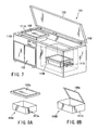
- FIG. 4 is a perspective view showing an appearance of a sterilization container according to the second embodiment of the present invention
- FIG. 5 is a plan view showing an opened state of the lid of the sterilization container of FIG. 4 .
- the tray 35 in which the endoscope storage portion 61 is disposed as the concave portion is used as the high temperature and pressure steam sterilization container for the endoscope to constitute the endoscope cleaning and sterilizing system.
- a sterilization container 70 shown in FIG. 4 is used as the high temperature and pressure steam sterilization container for the endoscope to constitute the endoscope cleaning and sterilizing system. Since the other constitution is similar to the above-described first embodiment, the description is omitted, and the same constitution is denoted with the same reference numerals for the description.
- the sterilization container 70 which is the high temperature and pressure steam sterilization container for the endoscope, a container main body 70a and a lid 70b are disposed.
- the container main body 70a is sealed by the lid 70b and constituted so that the steam is capable of entering but the liquid is incapable of entering the container. Therefore, the sterilization container 70 is capable of holding the sterilization in the sealed state as it is after the autoclave sterilization.
- the sterilization container 70 is formed of a material having resistance to the high temperature and pressure steam at the autoclave sterilization (high temperature and pressure steam sterilization) time.
- the endoscope storage portion 61 similar to that of the above-described first embodiment is disposed in the container main body 70a of the sterilization container 70.
- the endoscope 2 and the member and the like detached from the endoscope 2 are stored in this endoscope storage portion 61.
- a water injection cap 71, a treatment channel cleaning cap 72, an air or water feeding cleaning cap 73, and a water discharge cap 74 are protruded from the side wall surface of the container main body 70a. Outer end portions of these water injection cap 71, treatment channel cleaning cap 72, air or water feeding cleaning cap 73, and water discharge cap 74 are detachably connectable to the water injection port 43 of the endoscope cleaning device 40 of the first embodiment, and caps corresponding to the treatment channel cleaning tool 44, air or water feeding cleaning tool 45, and water discharge tool 46.
- Inner end portions of these caps are extended into the container main body 70a as shown in FIG. 5 , and are shaped in the same manner as in the water injection port 43, treatment channel cleaning tool 44, air or water feeding cleaning tool 45, and water discharge tool 46 of the endoscope cleaning device 40 described in the above-described first embodiment. It is to be noted that, additionally, further cleaning tools for cleaning separate pipe lines and the like may also be disposed in the sterilization container 70 in accordance with the function of the endoscope.
- a steam injection cap 75 and steam discharge cap 76 for use at an autoclave treatment time are protruded from the side wall surface of the container main body 70a.
- the outer end portions of these steam injection cap 75 and steam discharge cap 76 are detachably connectable to caps for steam injection and discharge (not shown) disposed in the autoclave device 50.
- the inner end portions of these steam injection cap 75 and steam discharge cap 76 have shapes suitable for the steam injection and discharge.
- handles 77 are disposed on the opposite ends of the container main body 70a. When these handles 77 are grasped, the sterilization container 70 is easily transported.
- the function of the present embodiment constituted as described above will be described.
- the endoscope 2 and the member and the like detached from the endoscope 2 are stored in the predetermined places of the endoscope storage portion 61 of the sterilization container 70.
- the sterilization container 70 is stored in the cleaning bath 41 of the endoscope cleaning device 40. At this time, the sterilization container 70 is pushed and stored into the cleaning bath 41 of the endoscope cleaning device 40. Then, the caps corresponding to the water injection port 43, treatment channel cleaning tool 44, air or water feeding cleaning tool 45, and water discharge tool 46 of the endoscope cleaning device 40 are easily (naturally) connected to the water injection cap 71, treatment channel cleaning cap 72, air or water feeding cleaning cap 73, and water discharge cap 74.
- the user closes the lid 70b, and operates the endoscope cleaning device 40 to clean the endoscope. After ending the cleaning, the user removes the sterilization container 70 from the endoscope cleaning device 40.
- the user stores the sterilization container 70 in which the endoscope 2 and the member and the like detached from the endoscope 2 remain to be stored in the chamber 51 in the autoclave device 50.
- the sterilization container 70 is pushed and stored in the chamber 51 in the autoclave device 50, the caps for steam injection and discharge of the autoclave device 50 are easily (naturally) connected to the steam injection cap 75 and steam discharge cap 76.
- the autoclave sterilization (high temperature and pressure steam sterilization) is performed in this state.
- the sterilization container 70 of the present embodiment itself has a function of cleaning bath 41 in the endoscope cleaning device 40, and also has a function of the chamber 51 in the autoclave device 50. Needless to say, the sterilization container 70 is locked not to break the sealed and closed state of the sterilization container 70 while the cleaning and autoclave sterilization are performed.
- the sterilization container 70 of the present embodiment is capable of performing the cleaning and sterilizing without being opened, after the endoscope 2 and the member and the like detached from the endoscope 2 are stored in the sterilization container 70. Thereafter, the members can be stored while the sterilization is held. Therefore, when the endoscope 2 used in the endoscopic inspection or the like is cleaned, and thereafter subjected to the autoclave sterilization treatment, the operation is facilitated.
- the sterilization container 70 of the present embodiment itself serves as the chamber 51 in the autoclave device 50. Therefore, since the device can be operated with a minimum steam amount necessary for sterilizing the endoscope 2 and the member and the like detached from the endoscope 2, a series of sterilization cycle can be shortened.
- the endoscope cleaning and sterilizing system of the second embodiment further saves a user's trouble as compared with the above-described first embodiment.
- FIG. 6 is an explanatory view showing a hanger device disposed in a trolley 80.
- apparatuses necessary for constructing an endoscope image are stored in the trolley 80.
- a hanger 90 from which the endoscope 2 is hung on standby immediately before the inspection is attached to a part of the trolley 80.
- the hanger 90 is constituted of a head portion 91 and a base portion 92.
- the head portion 91 is constituted of a connecting portion 93 and an endoscope attaching portion 94. This head portion 91 has a resistance to the autoclave sterilization.
- the connecting portion 93 of the head portion 91 is detachably attached to the base portion 92.
- the endoscope attaching portion 94 is detached from the base portion 92 together with the endoscope 2 after the endoscopic inspection, cleaned, and autoclaved and sterilized. Furthermore, after the sterilization, the endoscope attaching portion 94 attached to the endoscope 2 is connected to the base portion 92.
- the endoscope 2 is hung from the hanger on standby immediately before the inspection in many cases.
- this sterilized endoscope 2 is hung, there is also a possibility of contamination by the hanger.
- the hanger has not heretofore been autoclaved and sterilized together with the endoscope which can be autoclaved and sterilized.
- the hanger 90 of FIG. 6 when the sterilized endoscope 2 is on standby immediately before the inspection, the hanger 90 from which the endoscope 2 is to be hung is constituted in such a manner that the head portion 91 may be autoclaved and sterilized together with the endoscope 2 so as to prevent the contamination by the hanger 90.
- the endoscope 2 is detached from the endoscope attaching portion 94 and used. In this manner, the endoscope 2 (operation portion 8 or insertion portion 7) does not contact the member which has not been autoclaved and sterilized until the endoscopic inspection.
- the hanger 90 from which the endoscope 2 is to be hung can be autoclaved and sterilized together with the endoscope 2, and accordingly there is not a possibility that the endoscope 2 on standby is contaminated immediately before the inspection.
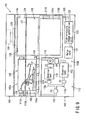
- FIG. 7 shows the appearance of an endoscope cleaning, disinfecting and sterilizing device 101 which is a reproducing treatment device of the used endoscope of the present embodiment.
- This endoscope cleaning, disinfecting and sterilizing device 101 is provided with a device main body 102 having a substantial box shape.
- An openable and closable lid body 103 is disposed on the upper surface of the device main body 102.
- This lid body 103 is rotatably connected to a back wall portion of the device main body 102 via a hinge portion 104.
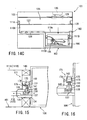
- a substantially L-shaped endoscope treatment chamber 102A is disposed on an upper-part side, and a machine chamber 102B is disposed on a lower side of the endoscope treatment chamber 102A in the device main body 102. Furthermore, a tray 106 is disposed in the endoscope treatment chamber 102A. Materials to be cleaned and sterilized such as an endoscope 105 which is a treatment object are stored in the tray 106.
- the tray 106 includes a tray 106A of a lid separated type as shown in FIG. 8A , and a tray 106B of a lid integral structure type as shown in FIG. 8B .
- a tray main body 107a having a substantial box shape whose upper surface is opened, and a tray lid 108a having the separated structure are combined and constituted.
- the upper surface opening of the tray main body 107a is opened and closed by the tray lid 108a having the separated structure.
- a tray lid 108b is rotatably connected and constituted to one side portion of the upper surface opening of a tray main body 107b having the substantial box shape whose upper surface is opened via a hinge portion in the tray 106B of the lid integral structure type.
- either of the tray 106A of the lid separated type or the tray 106B of the lid integral structure type may be used in the tray 106.
- a tray moving path 109 bent in a substantial L shape is disposed in the endoscope treatment chamber 102A of the device main body 102.
- This tray moving path 109 is constituted of a transverse moving path 109a and a vertical moving path 109b.
- the transverse moving path 109a holds the tray 106 so that the tray is movable in a transverse direction (right or left direction) in FIG. 9 .
- the vertical moving path 109b holds the tray 106 so that the tray is movable in a longitudinal direction (vertical direction) on a right end portion side of the transverse moving path 109a in FIG. 9 .
- a first treatment section (first treatment means) 110A is formed in a left-side portion (side portion of the vertical moving path 109b) in FIG. 9 in the transverse moving path 109a.
- the first treatment section 110A cleans or cleans and disinfects the endoscope 105 in the tray 106.
- a tray connecting portion 111A is disposed in the side wall portion of the first treatment section 110A. The tray connecting portion 111A is detachably connected to the tray 106.
- a second treatment section (second treatment means) 110B is disposed in a portion of the vertical moving path 109b below the transverse moving path 109a in FIG. 9 .
- the second treatment section 110B is a chamber for sterilization, which sterilizes the endoscope 105 cleaned or cleaned and disinfected in the first treatment section 110A.
- a tray connecting portion 111B and a discharge portion are disposed in the side wall portion of the second treatment section 110B.
- the tray connecting portion 111B is detachably connected to the tray 106.
- the discharge port (not shown) is constituted in the same manner as in a discharge port 119 of the first treatment section 110A. Moreover, this discharge port is detachably connected to a solution discharge valve 133 of the tray 106. It is to be noted that the discharge port 119 of the second treatment section 110B is connected to a discharge pipe line (not shown).
- a first treatment unit 112 is disposed in a portion under the transverse moving path 109a in the first treatment section 110A.
- a cleaning tank 113 and a chemical tank 114 are disposed in the first treatment unit 112.
- a cleaning solution for use in the cleaning process of the first treatment section 110A is stored in the cleaning tank 113.
- An antiseptic solution for use in the disinfecting process of the first treatment section 110A is stored in the chemical tank 114.
- this first treatment unit 112 is used in cleaning or cleaning and disinfecting the endoscope 105 in the tray 106.
- fluid pipe lines 115a, 115b connected in parallel with each other are disposed in the first treatment unit 112.
- one fluid pipe line 115a is provided with the cleaning tank 113
- the other fluid pipe line 115b is provided with the chemical tank 114.
- the cleaning tank 113 on a downstream side in the fluid pipe line 115a is connected to a pump P1 on a suction port side via an electromagnetic valve V2.
- the chemical tank 114 on the downstream side in the fluid pipe line 115b is combined with the fluid pipe line 115a via an electromagnetic valve V1. This combined portion is connected to the common pump P1 on the suction port side.
- the pump P1 on a discharge port side is connected to an inlet portion of a supply pipe line 116.
- a tray side pipe line connecting portion 117a and a first main body side transmission and reception unit 117b are disposed in the tray connecting portion 111A of the first treatment section 110A of the device main body 102.
- the first main body side transmission and reception unit 117b controls the opening and closing of valves for opening and closing the pipe lines 131a, 131b described later in the tray 106.
- the tray side pipe line connecting portion 117a of the tray connecting portion 111A is connected to an outlet portion of the supply pipe line 116.
- the cleaning tank 113 on an upstream side in the fluid pipe line 115a is connected to a pump P2 on a discharge port side via an electromagnetic valve V4.
- the chemical tank 114 on the upstream side in the fluid pipe line 115b is connected to the pump P2 common to the fluid pipe line 115a on the discharge port side via an electromagnetic valve V3.
- This pump P2 on the suction port side is connected to one end of a discharge pipe line 118.
- the other end of the discharge pipe line 118 is connected to the discharge port 119 of the first treatment section 110A.
- a second treatment unit 120 is disposed in a part under the second treatment section 110B.
- the second treatment unit 120 is a sterilization unit for performing a high-pressure steam sterilization with respect to the endoscope 105 in the tray 106.
- This second treatment unit 120 is provided with a water tank 121 for autoclave and a high-pressure steam generation unit 122.
- a high-pressure steam for the autoclave is generated in the high-pressure steam generation unit 122 with respect to the water for the autoclave supplied to the high-pressure steam generation unit 122 from the water tank 121 for autoclave.
- the high-pressure steam generation unit 122 is connected to one end of a high-pressure steam supply pipe line 123.
- the tray connecting portion 111B of the second treatment section 110B is provided with a tray-side pipe line connecting portion 124a and a second main body side transmission and reception unit 124b in the same manner as in the tray connecting portion 11.1A of the first treatment section 110A.
- the second main body side transmission and reception unit 124b controls the opening and closing of valves 131c, 131d for opening and closing the pipe lines described later on the side of the chamber for sterilization disposed in the tray 106.
- the tray-side pipe line connecting portion 124a of the tray connecting portion 111B is connected to the other end of the high-pressure steam supply pipe line 123.
- a chamber lid 110C is disposed above the second treatment section 110B.
- the chamber lid 110C has a structure resistant to the high pressure in the chamber of the second treatment section 110B at the sterilization time.
- the chamber lid 110C is constituted to be automatically openable and closable by control means of the device main body 102 of the endoscope cleaning, disinfecting and sterilizing device 101.
- tray conveying means 125 is disposed in the device main body 102.
- the tray conveying means 125 conveys the tray 106 between the first treatment section 110A and the second treatment section 110B.
- the tray conveying means 125 is provided with a belt conveyor 126 and a rail 127 for conveying the tray.
- the belt conveyor 126 is disposed on the floor surface of the transverse moving path 109a.
- the rail 127 for conveying the tray is extended along a conveying direction in the transverse direction of the tray 106 in the inner wall surface of the device main body 102 to control a conveying position of the tray 106.
- a rail control unit 128 is disposed in a terminal end portion of the rail 127 for conveying the tray. The rail control unit 128 detaches the tray 106 from the rail 127 for conveying the tray.
- an adsorption member 129 and a motor 130 for lifting up and down are disposed in a ceiling part of the vertical moving path 109b.
- the adsorption member 129 temporarily holds the tray 106 in an upper part of the second treatment section 110B which is the chamber for sterilization.
- the motor 130 for lifting up and down generates a driving force for moving down the tray 106 temporarily held by the adsorption member 129 in the second treatment section 110B.
- the tray 106 is temporarily held by the adsorption member 129 in the connecting portion between the transverse moving path 109a and the vertical moving path 109b at the moving time of the tray 106.
- the tray 106 is detached from the rail 127 for conveying the tray by the rail control unit 128.
- the tray 106 temporarily held by the adsorption member 129 is moved down into the second treatment section 110B by the motor 130 for lifting up and down. Therefore, when the cleaning and disinfecting process is completed in the first treatment section 110A, the tray 106 is conveyed into the second treatment section 110B which is the chamber for sterilization by the conveying means 125.
- valves 131a to 131d for opening and closing the pipe lines are disposed in the opposite side surfaces of a tray lid 108 of the tray 106.
- two valves 131a, 131b for opening and closing the pipe lines are disposed in one side surface of the tray lid 108.
- two valves 131c, 131d for opening and closing the pipe lines are similarly disposed in the other side surface of the tray lid 108. It is to be noted that these valves 131a to 131d for opening and closing the pipe lines may also be disposed in the opposite side surfaces of the tray main body 7.
- an inclined surface 132 inclined at an appropriate angle with respect to a horizontal plane is formed in a bottom part of the tray 106.
- a solution discharge valve 133 is disposed in a lowermost part of the inclined surface 132.
- the solution discharge valve 133 discharges a waste solution while the cleaning and disinfecting is performed in the tray 106.
- the solution discharge valve 133 of the tray 106 is structured in the same manner as in the valves 131a, 131b for opening and closing the pipe lines. Moreover, the waste solution and the like in the tray 106 can be securely discharged from the solution discharge valve 133.
- FIG. 11 shows the inner structures of the respective valves 131a to 131d for opening and closing the pipe lines of the tray 106. It is to be noted that basic structures of the valves 131a to 131d for opening and closing the pipe lines are modifications of the structure of the electromagnetic valve, and all the valves have the same structure. Moreover, here the constitution of one valve 131 for opening and closing the pipe line will be described.
- reference numeral 134 denotes an opening for attaching the valve, formed in one side part of the tray 106.
- This opening 134 is connected to a pipe line constituting member 135 of the valve 131 for opening and closing the pipe line.
- a valve body 136 of the valve 131 for opening and closing the pipe line for opening and closing this pipe line is disposed midway in the pipe line of the pipe line constituting member 135.
- This valve body 136 is movably supported in a direction (opening and closing direction) crossing a center line direction of the pipe line constituting member 135 at right angles.
- a communicating port 137 is disposed in the pipe line of the pipe line constituting member 135. The communicating port 137 is opened and closed by the valve body 136 of the valve 131 for opening and closing the pipe line.
- a packing 138 for securely opening and closing the valve 131 is disposed in the valve body 136 of the valve 131 for opening and closing the pipe line. Furthermore, a plunger 139 for moving and operating the valve body 136 in the opening and closing direction is disposed in the valve 131 for opening and closing the pipe line.
- a sealing material 141 is disposed around a shaft 140 of the plunger 139. Furthermore, a coil 142 is disposed on an outer periphery of the plunger 139.
- a coil spring 143 is disposed in the upper part of the plunger 139. Moreover, usually (at a time when power is not supplied to the coil 142), as shown in FIG. 12 , the valve body 136 of the valve 131 for opening and closing the pipe line is allowed to abut on a valve seat portion of a peripheral edge of the communicating port 137 and urged in a direction for closing the communicating port 137 by a spring force of the coil spring 143. This achieves a structure in which the pipe line of the pipe line constituting member 135 is blocked midway.
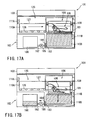
- FIG. 9 shows a state in which the tray 106 is disposed in the first treatment section 110A of the device main body 102, and the supply pipe line 116 of the tray side pipe line connecting portion 117a in the tray connecting portion 111A of the first treatment section 110A is connected to the pipe line of the pipe line constituting member 135 of the tray 106. In this state, in FIG.
- each tray side transmission and reception unit 144 for two valves 131a, 131b for opening and closing the pipe lines in the left-side surface of the tray 106 is disposed in a position corresponding to the first main body side transmission and reception unit 117b of the device main body 102. Moreover, the tray side transmission and reception unit 144 on the side of the tray 106 is controlled by the first main body side transmission and reception unit 117b. At this time, the coil 142 of the valve 131 for opening and closing the pipe line is driven by the tray side transmission and reception unit 144 to control the opening and closing operations of the respective valves 131a, 131b for opening and closing the pipe lines.
- the plunger 139 is moved in an adsorbed direction on the coil 142 side against the spring force of the coil spring 143.
- the valve body 136 of the valve 131 for opening and closing the pipe line is detached from the valve seat portion of the peripheral edge of the communicating port 137.
- the communicating port 137 is opened to release the pipe line of the pipe line constituting member 135.
- the cleaning solution or antiseptic solution is supplied into the tray 106 of the first treatment section 110A to clean and disinfect the endoscope 105 in the tray 106.
- one of the valves 131a, 131b for opening and closing the pipe lines of the tray 106 connected to the tray connecting portion 111A of the first treatment section 110A is connected to one end of a cleaning and disinfecting tube 159.
- the other end of the cleaning and disinfecting tube 159 is connected to various channels of the endoscope 105.
- the insides of various channels of the endoscope 105 can be cleaned securely at the cleaning and disinfecting time of the endoscope 105 in the first treatment section 110A.
- the solution discharge valve 133 of the tray 106 is connected to the discharge port 119 of the first treatment section 110A in a state in which the tray connecting portion 111A of the first treatment section 110A is connected to the tray 106.
- the discharge port 119 of the first treatment section 110A is connected to the discharge pipe line 118.
- the waste solution during the cleaning and disinfecting of the endoscope 105 in the tray 106 in the first treatment section 110A is discharged to the discharge pipe line 118 from the solution discharge valve 133 via the discharge port 119 of the first treatment section 110A.
- FIG. 14C shows a state in which the tray 106 moves to the second treatment section 110B.
- the high-pressure steam supply pipe line 123 of the tray-side pipe line connecting portion 124a in the tray connecting portion 111B is connected to the pipe line of the pipe line constituting member 135 of the tray 106.
- each tray side transmission and reception unit 144 for two valves 131c, 131d for opening and closing the pipe lines in the right-side surface of the tray 106 is disposed in the position corresponding to the second main body side transmission and reception unit 124b of the device main body 102.
- the tray side transmission and reception unit 144 on the tray 106 side is controlled by the second main body side transmission and reception unit 124b of the device main body 102, and the opening and closing operations of the respective valves 131c, 131d for opening and closing the pipe lines are controlled.
- the tray side transmission and reception unit 144 of the tray 106 transmits and receives power and data with respect to the first main body side transmission and reception unit 117b and second main body side transmission and reception unit 124b of the device main body 102 by a method without any electric contact. Accordingly, a driven state of each valve 131 and an operation state of each valve 131 can be detected.
- the RFID generally includes “electromagnetic coupling system”, “electrostatic coupling system”, “electromagnetic inductive system”, “microwave system”, and “optical communication system”.
- the "electromagnetic coupling system”, “electromagnetic inductive system”, and “microwave system” are capable of fulfilling more effect. It is to be noted that the application is possible even in another case.
- the tray connecting portion 111A of the first treatment section 110A in the device main body 102 and the tray connecting portion 111B of the second treatment section 110B are provided with adsorption members 145 such as an electromagnet and suction unit.
- the adsorption member 145 adsorbs the tray 106 in a state in which the tray 106 is disposed in the first treatment section 110A. Accordingly, the tray is held in a state in which the first main body side transmission and reception unit 117b is securely connected to the tray side transmission and reception unit 144.
- the adsorption member 145 adsorbs the tray 106 in a state in which the tray 106 is disposed in the second treatment section 110B. Accordingly, the tray is held in a state in which the second main body side transmission and reception unit 124b is securely connected to the tray side transmission and reception unit 144. It is to be noted that the electromagnet, suction method by a vacuum pump or the like, or mechanical holding means may also be used in the adsorption member 145.
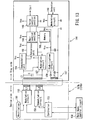
- FIG. 13 shows an electric circuit of the tray side transmission and reception unit 144 and the first main body side transmission and reception unit 117b (second main body side transmission and reception unit 124b) in the endoscope cleaning, disinfecting and sterilizing device 101.
- the tray side transmission and reception unit 144 is provided with main control sections 146 such as CPU, a transmission and reception circuit 147, a power supply circuit, a valve control section 148, and a conversion circuit 149 for converting the signal of a detection unit (not shown) disposed in the valve 131 for opening and closing the pipe line into a digital signal or the like.
- main control sections 146 such as CPU, a transmission and reception circuit 147, a power supply circuit, a valve control section 148, and a conversion circuit 149 for converting the signal of a detection unit (not shown) disposed in the valve 131 for opening and closing the pipe line into a digital signal or the like.
- the first main body side transmission and reception unit 117b (second main body side transmission and reception unit 124b) is provided with a modulation circuit 150 for preparing and transmitting the transmission signal to the tray side transmission and reception unit 144, a transmission coil L1, and an oscillation unit 151. Furthermore, a reception coil L2 for receiving the signal from the tray side transmission and reception unit 144, a demodulation circuit 152, and a controller 153 for controlling the constitution are disposed. The controller 153 is connected to a main body control circuit 158 having a function of controlling various units.
- a coil L3 for transmitting and receiving the signal; a capacitor C for resonance; a demodulation unit 154 for demodulating a reception signal; a conversion unit 155; a memory 156 in which data of the conversion unit 155 is stored; a main control section 146 for controlling the conversion unit 155 and memory 156 to control communication with the main body; and a modulation circuit 157 for the transmission.
- the signal received by a coil L4 is smoothed and rectified by a stabilization circuit 158 and supplied to each circuit to achieve the power supply for driving these circuits.
- the endoscope cleaning, disinfecting and sterilizing device 101 of the present example is used after the end of the diagnosis by the endoscope 105.
- the used endoscope 105 is set in the endoscope cleaning, disinfecting and sterilizing device 101.
- the endoscope 105 is disposed in the tray 106.
- the cleaning and disinfecting tube 159 is connected to the endoscope 105.
- the tray 106 is set in the first treatment section 110A to clean or clean and disinfect the endoscope 105 in a state in which the lid 108 of the tray 106 is closed.
- the supply pipe line 116 of the tray side pipe line connecting portion 117a in the tray connecting portion 111A of the first treatment section 110A is connected to the pipe line of the pipe line constituting member 135 of two valves 131a, 131b for opening and closing the pipe lines on the left-side surface of the tray 106.
- the tray 106 is adsorbed by the adsorption member 145 in a state in which the tray 106 is disposed in the first treatment section 110A. Accordingly, the first main body side transmission and reception unit 117b is securely connected to the tray side transmission and reception unit 144.
- an initial state is set, and the cleaning process is automatically started.
- the radio frequency identification (RFID) system automatically operates by the control signal from the main body control circuit 158 in the device main body 102. At this time, data communication is performed between the tray side transmission and reception unit 144 of the tray 106 and the first main body side transmission and reception unit 117b.
- RFID radio frequency identification
- a radio frequency signal digital-modulated by the modulation circuit 150 is applied to the transmission coil L1 in accordance with write command and write information transmitted as serial signals from the controller 153 of the first main body side transmission and reception unit 117b.
- the signal induced in the coil L3 of the tray side transmission and reception unit 144 is amplified, and demodulated to an original digital signal in the demodulation unit 154.
- digitized serial signal information is converted to a parallel signal by the conversion unit 155, and the information is stored in the data memory 156.
- the control signal is transferred to the valve control section 148 by the signal from the main control section 146.
- the coil 142 of the valve 131 for opening and closing the pipe line is driven by the control signal output from the valve control section 148.
- the valves 131a, 131b for opening and closing the pipe lines are released to secure the pipe line for the cleaning and disinfecting.
- the cleaning solution or the antiseptic solution is supplied into the tray 106 of the first treatment section 110A to clean and disinfect the endoscope 105 in the tray 106.
- the cleaning solution or the antiseptic solution is supplied into various channels of the endoscope 105 from the cleaning and disinfecting tube 159 to securely clean the inside of various channels of the endoscope 105.
- waste solution during the cleaning and disinfecting of the endoscope 105 in the tray 106 by the first treatment section 110A is discharged to the discharge pipe line 118 from the solution discharge valve 133 via the discharge port 119 of the first treatment section 110A.
- read operation information (data) of the valves 131a, 131b for opening and closing the pipe lines are transmitted to the main control section 146 and memory 156 from the detection unit via the conversion circuit 149.
- the parallel information read from the memory 156 is converted into the serial signal in synchronization with a non-modulated signal sent from the transmission coil L1.
- it is controlled whether or not the coil L3 and the tank circuit by the capacitor C for resonance are brought into a resonance state in response to the signal in the modulation circuit 157.
- it is detected whether or not to resonate the tank circuit of the tray side transmission and reception unit 144 via the reception coil L2 on the controller 153 side of the first main body side transmission and reception unit 117b to exchange the information.
- electromagnetic valves V2, V4 are switched and operated into the open state
- electromagnetic valves V1, V3 are switched and operated into the closed state
- the pumps P1, P2 are driven at the start time of the cleaning process of the endoscope 105 in the tray 106 in the first treatment section 110A.
- the cleaning section sent from the cleaning tank 113 is supplied into the tray 106 from one fluid pipe line 115a and supply pipe line 116 via various pipe lines such as the tray side pipe line connecting portion 117a in the tray connecting portion 111A of the first treatment section 110A to clean the endoscope 105 in the tray 106.
- a part of the cleaning section flows into various channels of the endoscope 105 through the cleaning and disinfecting tube 159 to clean the inside of various channels of the endoscope 105.
- the solution discharge valve 133 of the tray 106 connected to the discharge port 119 of the first treatment section 110A is held in the open state during the cleaning process of the endoscope 105. Therefore, the waste solution in the tray 106 is returned into the cleaning tank 113 via the discharge pipe line 118. Therefore, the cleaning section is circulated in the above-described path to clean the endoscope 105 in the tray 106 and the inside of the various channels of the endoscope 105 during the cleaning process.
- the driving of the pump P1 is stopped after elapse of a defined time of the cleaning process.
- the cleaning section in the tray 106 is returned into the cleaning tank 113 via the discharge pipe line 118 by the pump P2, the cleaning section is recovered, and the cleaning process ends.
- the present example includes a constitution in which the cleaning section is recovered, but a pipe line for discharging the cleaning section to the discharge port of facilities may also be disposed to discharge the solution to the outside of the device.
- the electromagnetic valves V2, V4 shown in FIG. 9 are closed, and the electromagnetic valves V1, V3 are opened.
- the pumps P1, P2 are driven to start the disinfecting process.
- the antiseptic solution sent from the chemical tank 114 is supplied into the tray 106 from one fluid pipe line 115b and supply pipe line 116 via various pipe lines such as the tray side pipe line connecting portion 117a in the tray connecting portion 111A of the first treatment section 110A to disinfect the endoscope 105 in the tray 106.
- a part of the antiseptic solution flows into various channels of the endoscope 105 through the cleaning and disinfecting tube 159 to disinfect the inside of various channels of the endoscope 105.
- the solution discharge valve 133 of the tray 106 connected to the discharge port 119 of the first treatment section 110A is held in the open state during the disinfecting process of the endoscope 105. Therefore, the waste solution in the tray 106 is returned into the chemical tank 114 via the discharge pipe line 118. Therefore, the antiseptic solution is circulated in the above-described path to disinfect the endoscope 105 in the tray 106 and the inside of the various channels of the endoscope 105 during the disinfecting process of the endoscope 105. It is to be noted that an immersed state is sometimes temporarily held without circulating the antiseptic solution by a medicinal effect of the chemical.
- the driving of the pump P1 is stopped after the elapse of the defined time of the disinfecting process.
- the antiseptic solution in the tray 106 is returned into the chemical tank 114 via the discharge pipe line 118 by the pump P2, the antiseptic solution is recovered, and the disinfecting process ends. It is to be noted that a rinsing process may also be performed after the disinfecting process.
- the data communication is started again between the tray side transmission and reception unit 144 of the tray 106 and the first main body side transmission and reception unit 117b at the time of the end of the disinfecting process. Accordingly, the tray side transmission and reception unit 144 closes the valves 131a, 131b for opening and closing the pipe lines, and also closes the pipe line of the cleaning and disinfecting tube 159. At this time, the solution discharge pipe line between the solution discharge valve 133 of the tray 106 and the discharge port 119 of the first treatment section 110A also closes. Therefore, the tray 106 is sealed in a state in which the endoscope 105 is stored, and the endoscope 105 is prevented from being contaminated from the outside of the tray 106.
- the tray 106 kept in the sealed state is conveyed on the right side by the belt conveyor 126 and rail 127 for conveying the tray constituting the tray conveying means 125 in FIG. 9 .
- the tray 106 is conveyed to an upper part position of the second treatment section 110B. It is to be noted that, as shown in FIG. 14A , when the tray 106 is conveyed to the upper part position of the second treatment section 110B, the lid for the chamber 110C is in the opened state.
- the tray 106 when the tray 106 is conveyed to the upper part position of the second treatment section 110B, the tray 106 is adsorbed by the adsorption member 129, the rail control unit 128 operates, and the tray 106 is released from the rail 127 for conveying the tray.
- the motor 130 for lifting up and down operates.
- the tray 106 adsorbed by the adsorption member 129 moves downward in the vertical moving path 109b and is conveyed into the second treatment section 110B.
- the tray 106 is set in a predetermined set position inside the second treatment section 110B.
- the high-pressure steam supply pipe line 123 of the tray-side pipe line connecting portion 124a in the tray connecting portion 111B of the second treatment section 110B is connected to the pipe line of the pipe line constituting member 135 of two valves 131c, 131d for opening and closing the pipe lines on the right-side surface of the tray 106.
- the second main body side transmission and reception unit 124b is securely connected to the tray side transmission and reception unit 144 in a state in which the tray 106 is disposed in the second treatment section 110B.
- the solution discharge valve 133 of the tray 106 is connected to the discharge port of the second treatment section 110B, and the discharge port of the second treatment section 110B is connected to the discharge pipe line.
- the adsorption member 129 operates, and the tray 106 is released from the adsorption member 129. Thereafter, as shown in FIG. 14C , the chamber lid 110C closes, and the preparation for the sterilizing process in the second treatment section 110B is completed.
- the chamber lid 110C is fixed by a lid fixing member 60 for the chamber in a state in which the lid is capable of securely bearing the high pressure.
- the next sterilizing process is started in this state.
- the data communication is started between the tray side transmission and reception unit 144 of the tray 106 and the second main body side transmission and reception unit 124b, and the valves 131c, 131d for opening and closing the pipe lines are released by the tray side transmission and reception unit 144.
- the solution discharge valve 133 of the tray 106 is controlled in the closed state.
- the water in the water tank 121 for autoclave is supplied to the high-pressure steam generation unit 122, and is converted to the high-pressure steam by the high-pressure steam generation unit 122.
- the high-pressure steam supplied from the high-pressure steam generation unit 122 is supplied into the tray 106 of the second treatment section 110B via the high-pressure steam supply pipe line 123, and the endoscope 105 in the tray 106 and the inside of various channels of the endoscope 105 are subjected to the sterilization treatment for the defined time.
- the solution discharge valve 133 is released, and the high-pressure steam used in the sterilization treatment is discharged to the solution discharge pipe line via the solution discharge valve 133 from the tray 106, and thereafter discharged to an outside discharge port.
- the tray 106 is removed from the second treatment section 110B and conveyed to the initial first treatment section 110A by the tray conveying means 125, and the endoscope 105 in the tray 106 is dried.
- a series of the respective processes of the cleaning and disinfecting and sterilizing treatment of the endoscope 105 in the curved portion 16 are all completed.
- the vacuum pump or drying means by hot air is incorporated in the present device, and a drying process may also be incorporated before or after the sterilization treatment.
- the above-described constitution produces the following effect. That is, in the endoscope cleaning, disinfecting and sterilizing device 101, the first treatment unit 112 for cleaning or cleaning and disinfecting the endoscope 105 and the second treatment unit 120 for sterilizing the endoscope 105 are integrated and incorporated in the device main body 102, and therefore cost of the whole device can be reduced. Furthermore, all the processes of the cleaning and disinfecting and sterilizing treatment of the endoscope 105 are controlled by the main body control circuit 158 of the endoscope cleaning, disinfecting and sterilizing device, 101, and all the cleaning and disinfecting and sterilizing can be automatically performed.
- the whole device can be miniaturized as compared with a case where the treatment unit for cleaning or cleaning and disinfecting the endoscope 105 is independently separated from the treatment unit for sterilizing the endoscope 105. Therefore, the device 1 which easily performs the respective cleaning and disinfecting and sterilizing operations can be installed even in a general consultation room where the diagnosis is conducted with the endoscope 105.
- the endoscope 105 when the endoscope 105 is conveyed between the first treatment section 110A and second treatment section 110B by the tray conveying means 125 in the device main body 102, a time required for the respective cleaning and disinfecting and sterilizing operations of the endoscope 105 or the like performed between cases of the endoscopic diagnosis can be reduced, and efficiency of the endoscopic diagnosis can be enhanced. Furthermore, since the endoscope 105 does not have to be set up every cleaning and disinfecting and sterilizing operation process of the endoscope 105 or the like as in the related art, the number of user's reprocesses can be largely reduced.
- the tray 106 for the cleaning and disinfecting and sterilizing is used in common in the device main body 102, and all the cleaning, disinfecting, and sterilizing treatments can be automatically performed, the whole device can be miniaturized, and product cost can be largely reduced. Furthermore, since the tray 106 is detachably attached to the device main body 102, it is possible to hold the state of the endoscope 105 without changing the state in and after all the cleaning, disinfecting, and sterilizing processes.
- the tray 106 is detachably attached to the device main body 102, a plurality of endoscopes and the like can be treated in order in the same device 101. Therefore, operation ratio of the device 101 can be enhanced, and a running cost of the whole reprocess can be largely reduced. Furthermore, since the tray 106 for the cleaning and disinfecting and sterilizing is used in common, and all the cleaning, disinfecting, and sterilizing operation processes of the endoscope 105 and the like can be automatically performed, a reprocess time is reduced, a reprocess between the cases is possible, and the endoscopic inspection can be conducted with good efficiency.
- the cleaning section for use during the cleaning of the endoscope 105 is generally water, or water mixed with detergent for use, but instead of a method of storage in the cleaning tank 113, a water supply pipe line may also be connected directly to a city water pipe line or the like in the method.
- the cleaning and disinfecting processes are performed in the first treatment section 110A, but disinfecting means and disinfecting process are omitted, and only the cleaning and sterilizing processes may be performed in the device.
- FIGS. 15 and 16 show a further example.
- the constitution of each valve 131 for opening and closing the pipe line of the tray 106 in the endoscope cleaning, disinfecting and sterilizing device 101 is modified as follows.
- the constitution has been described in which the electric circuit applying the radio frequency identification (RFID) using the radio waves is disposed as the driving mechanism of the valve 131 for opening and closing the pipe line between the main body side transmission and reception units 117b, 124b and the tray side transmission and reception unit 144.
- a mechanical driving mechanism 171 of the valve 131 for opening and closing the pipe line is disposed.
- a cam member 172 is fixed to the shaft 140 of the plunger 139 for opening and closing the valve body 136 in the valve 131 for opening and closing the pipe line.
- a semicircular cam surface 173 is formed in this cam member 172.
- a pin insertion port 174 is formed in the side surface of the pipe line constituting member 135 of the valve 131 for opening and closing the pipe line. As shown in FIG. 16 , the pin insertion port 174 is disposed in a portion which is detached from or faces the cam surface 173 of the cam member 172 in a state in which the valve body 136 of the valve 131 for opening and closing the pipe line is allowed to abut on the valve seat portion of the peripheral edge of the communicating port 137 and is urged in a direction for closing the communicating port 137 by the spring force of the coil spring 143.
- a cam driving pin 175 is protruded from the wall surface in the vicinity of the tray side pipe line connecting portion 117a in the tray connecting portion 111A of the first treatment section 110A of the endoscope cleaning, disinfecting and sterilizing device 101 (tray-side pipe line connecting portion 124a in the tray connecting portion 111B of the second treatment section 110B).
- the cam driving pin 175 is detachably inserted into the pin insertion port 174 of the pipe line constituting member 135 of the valve 131 for opening and closing the pipe line.
- the tip portion of the cam driving pin 175 abuts on the cam surface 173 of the cam member 172.
- the shaft 140 of the plunger 139 moves in the upward direction in FIG. 15 by a cam function of the cam surface 173 of the cam member 172 to switch the valve 131 for opening and closing the pipe line into the released state.
- the endoscope 105 After the end of the diagnosis by the endoscope 105, the endoscope 105 is attached to the tray 106, and the tube for cleaning and disinfecting 159 is connected to the endoscope 105. Thereafter, the tray 106 is set in the first treatment section 110A to clean or clean and disinfect the endoscope 105 in a state in which the lid 108 of the tray 106 is closed.
- the supply pipe line 116 of the tray side pipe line connecting portion 117a in the tray connecting portion 111A of the first treatment section 110A is connected to the pipe line of the pipe line constituting member 135 of two valves 131a, 131b for opening and closing the pipe lines on the left-side surface of the tray 106. Furthermore, the cam driving pin 175 in the vicinity of the tray side pipe line connecting portion 117a in the tray connecting portion 111A of the first treatment section 110A of the endoscope cleaning, disinfecting and sterilizing device 101 is inserted into the pin insertion port 174.
- the tip portion of the cam driving pin 175 inserted in the pin insertion port 174 abuts on the cam surface 173 of the cam member 172, accordingly the shaft 140 of the plunger 139 moves in the upward direction in FIG. 15 by the cam function of the cam surface 173 of the cam member 172, and the valve 131 for opening and closing the pipe line is switched into the released state. Accordingly, the pipe line for the cleaning and disinfecting is secured. Moreover, the pipe line of the cleaning and disinfecting tube 159 is also secured. Furthermore, the valve 131 for opening and closing the pipe line is similarly switched in the released state also in the portion of the solution discharge valve 133 to secure the solution discharge pipe line. In this state, the cleaning and disinfecting processes are performed in the same manner.
- the tray 106 is removed from the first treatment section 110A by the tray conveying means 125.
- the cam driving pin 175 is pulled from the pin insertion port 174. Therefore, in this state, as shown in FIG. 16 , the valve body 136 of the valve 131 for opening and closing the pipe line is allowed to abut on the valve seat portion of the peripheral edge of the communicating port 137, and the communicating port 137 is closed by the spring force of the coil spring 143.
- the pipe line of the cleaning and disinfecting tube 159 is also closed.
- the solution discharge valve 133 is also closed, and the tray 106 is sealed and closed in a state in which the endoscope 105 is stored, the endoscope 105 is prevented from being contaminated from the outside of the tray 106.
- the tray 106 is conveyed to the second treatment section 110B by the tray conveying means 125.
- the high-pressure steam supply pipe line 123 of the tray-side pipe line connecting portion 124a in the tray connecting portion 111B of the second treatment section 110B is connected to the pipe line of the pipe line constituting member 135 of two valves 131c, 131d for opening and closing the pipe lines on the right-side surface of the tray 106.
- the cam driving pin 175 in the vicinity of the tray-side pipe line connecting portion 124a in the tray connecting portion 111B of the second treatment section 110B is inserted into the pin insertion port 174.
- the shaft 140 of the plunger 139 moves in the upward direction in FIG. 15 by the cam function of the cam surface 173 of the cam member 172 to switch the valve 131 for opening and closing the pipe line into the released state, the pipe line for supplying the high-pressure steam is secured, and the preparation for the sterilizing process is completed. Thereafter, the processes similar to those above are performed, and all the processes are completed.
- the mechanical driving mechanism 171 of the valve 131 for opening and closing the pipe line is disposed, the electric driving circuit is not used as the driving mechanism of the valve 131 for opening and closing the pipe line, and therefore heat resistance is also enhanced. Furthermore, the electric circuit in the vicinity of the second treatment section 110B as the sterilization chamber which easily reaches at the high temperature can be reduced, therefore the sterilization treatment at the high temperature (e.g., about 140°C) is further possible, and the time reduction, sterilization capability enhancement and the like of the sterilization treatment can be achieved with the raising of the sterilization temperature.
- the high temperature e.g., about 140°C
- valve 131 for opening and closing the pipe line can be simplified, further miniaturization is possible by reduction of constituting components, and further the reduction of the cost of the device 101 is possible.
- FIGS. 17A to 17C show a further example, not forming part of the claimed invention.
- the constitution of means for lifting up and down the tray 106 in the vertical moving path 109b of the tray moving path 109 in the endoscope cleaning, disinfecting and sterilizing device 101 ( FIG. 7 to FIGS. 14A to 14C ) is modified as follows.
- a float 181 is disposed to float the tray 106 using buoyancy of the liquid in the second treatment section 110B. Furthermore, a connection portion 183 connected to one end of a liquid pipe line 182 is disposed in the bottom part of the second treatment section 110B. An electromagnetic valve 184 for controlling the supply and discharge of the liquid into the second treatment section 110B is disposed in the connection portion 183.
- the other end of the liquid pipe line 182 is connected to a fluid tank 186 for storing the liquid via a fluid pump 185. Furthermore, when the fluid pump 185 is driven, the liquid is supplied into the second treatment section 110B from the fluid tank 186 and the liquid is discharged from the second treatment section 110B. Furthermore, the supply and discharge of the liquid into the second treatment section 110B is controlled by the electromagnetic valve 184. Accordingly, increase or decrease of the liquid to be supplied into the second treatment section 110B is adjusted, and the height of the float 181 in the second treatment section 110B is adjusted.
- the tray 106 conveyed on the second treatment section 110B side from the first treatment section 110A is laid on the float 181 in the second treatment section 110B.
- the supply and discharge of the liquid in the second treatment section 110B are controlled by the electromagnetic valve 184, and accordingly the tray 106 is lifted up and down in the vertical moving path 109b of the tray moving path 109.
- the electromagnetic valve 184 is released, and the fluid pump 185 operates. Accordingly, the liquid stored in the fluid tank 186 is supplied into the second treatment section 110B to raise the float 181. At this time, the float 181 is raised to a position substantially horizontal with respect to the belt conveyor 126.
- the tray conveying means 125 conveys the tray 106 above the second treatment section 110B. Moreover, when the rail control unit 128 releases the tray 106 in the terminal end position of the rail 127 for conveying the tray, as shown in FIG. 17A , the tray 106 is laid on the float 181.
- the tray 106 is set in the predetermined set position inside the second treatment section 110B, and the sterilizing process is executed in the same manner as before.
- the liquid is supplied into the second treatment section 110B by the fluid pump 185, the liquid level in the second treatment section 110B is accordingly raised, the tray 106 on the float 181 is lifted up, and an operation of returning the tray 106 to the initial position is performed.
- the above-described constitution produces the following effect. That is, when the liquid surface in the second treatment section 110B is adjusted using a fluid control technique, the tray 106 in the second treatment section 110B is accordingly lifted up and down. Therefore, as compared with the use of complicated mechanical tray lifting-up and down means, the device 101 can be miniaturized, the cost can be reduced, and quality can be stabilized.
- the fluid tank 186 is usable in common for the cleaning section, water for generating the high-pressure steam and the like. Therefore, by the reduction of the constituting components, the device 101 can further be miniaturized, and the cost reduction can be effectively realized.
- FIG. 18 shows a further example, not forming part of the claimed invention.
- the constitutions of the tray 106 and device main body 102 in the endoscope cleaning, disinfecting and sterilizing device 101 are modified as follows.
- a tray 191 which also serves as the sterilization chamber is disposed above the substantially box-shaped device main body 102. Furthermore, the lid body 103 of the device main body 102 is integrated with a tray lid 192 of the tray 191.
- the second main body side transmission and reception unit 124b is disposed in the vicinity of the tray 191. It is to be noted that the tray conveying means 125 is omitted, and the other structure and constitution of the valve 131 for opening and closing the pipe line of the tray main body, various transmission and reception units, cleaning unit, and sterilizing unit are similar to those mentioned before.
- the tray main body of the tray 191 is detachably connected to the device main body 102. Moreover, a preliminary tray 191 is attached to the device main body 102, and it is possible to further enhance the efficiency in all the processes.
- the tray 191 which also serves as the sterilization chamber is disposed in the upper part of the device main body 102, and the lid body 103 of the device main body 102 is integrated with the tray lid 192 of the tray 191. Therefore, the whole endoscope cleaning, disinfecting and sterilizing device 101 can further be miniaturized, and the cost reduction can be achieved.
- the endoscope 105 can be easily removed from the tray 191, and the number of user's disinfecting and sterilizing treatment processes can further be reduced.
- FIGS. 19 and 20A to 20C show a further example, not forming part of the claimed invention.
- the constitution of the valve 131 for opening and closing the pipe line of the tray 106 in the endoscope cleaning, disinfecting and sterilizing device 101 is modified as follows.
- a check valve 201 which opens by application of the pressure from the outside is disposed in the tray 106.
- the check valve 201 is provided with a cylindrical casing 203.
- the casing 203 is protruded outwards from the periphery of a liquid inflow hole 202 formed in the side wall of the tray 106.
- a tapered valve receiving portion 204 is formed in the tip portion of the casing 203.
- a ball-shaped valve body 205 and a coil spring 206 are disposed in the casing 203.
- the valve body 205 opens and closes a tip opening 204a of the valve receiving portion 204.
- the coil spring 206 urges the valve body 205 can be held the tip opening 204a of the valve receiving portion 204 is closed.
- tray connecting connectors 207 shown in FIGS. 20A, 20B are disposed in the first and second treatment sections 110A and 110B of the device main body 102.
- a connector main body 208 detachably connected to the casing 203 of the check valve 201 is disposed in the connector 207.
- a bar-shaped operation rod 209 is protruded from an axial center portion of the connector main body 208. This operation rod 209 is inserted into the tip opening 204a of the valve receiving portion 204.
- the check valve 201 of the tray 106 is inserted into and connected to the connector 207 of the first treatment section 110A or the second treatment section 110B.
- the operation rod 209 of the connector 207 is inserted into the tip opening 204a of the valve receiving portion 204 in the check valve 201.
- the valve body 205 of the check valve 201 is pushed in a direction far from the tip opening 204a of the valve receiving portion 204 against the spring force of the coil spring 206. Therefore, since the tip opening 204a of the valve receiving portion 204 is released, the check valve 201 is switched and operated in the open state to secure the flow path of the tray 106.
- the above-described constitution produces the following effect. That is, the check valve 201 which opens by the application of the pressure from the outside is disposed in the tray 106. Therefore, even without the electric control means such as the first main body side transmission and reception unit 117b and second main body side transmission and reception unit 124b, liquid or gas or steam for the cleaning or disinfecting or sterilizing can be easily supplied into the tray 106, and the constitution can be simplified.
- the valve body 205 can be held by the spring force of the coil spring 206 in the check valve 201 in a state in which the tip opening 204a of the valve receiving portion 204 is closed. As a result, foreign matters can be prevented from being mixed into the tray 106.
- the check valve 201 of the tray 106 may also be structured to open when the connector 207 of the device main body 102 is inserted and to close when the connector is pulled out.
- the valve may also be structured to open by a pressing force from the pressurized and fed liquid or gas or steam and to close when any pressure is not applied.
- FIG. 21 shows a modification of this example.
- a membrane filter film 211 in which micro holes having a hole diameter (e.g., about 0.2 micron) incapable of passing bacteria are formed is attached so as to cover the liquid inflow hole 202 of the tray 106.
- the tray 106 is set in the first treatment section 110A or the second treatment section 110B of the device main body 102, only the pressurized and fed liquid or gas or steam passes through the membrane filter film 211 to flow in the liquid inflow hole 202 of the tray 106.
- FIGS. 22A to 22C show an example not forming part of the claimed invention.
- the constitution of the endoscope cleaning, disinfecting and sterilizing device 101 is modified as follows.
- a bag 222 is disposed, and the whole tray 106 is covered with a film 221 (material or the like of a commercially available sterilized pack) capable of passing gas or steam but incapable of passing the foreign matters such as bacteria and dust.
- a film 221 material or the like of a commercially available sterilized pack
- the whole tray 106 is constituted to be covered with the bag 222.
- a thermally welded portion 223 is disposed in the peripheral edge of an opening 222a of the bag 222.
- the bag 222 is on standby in the terminal end position of a conveying track of the tray 106 conveyed by the belt conveyor 126 from the first treatment section 110A. Moreover, after the tray 106 conveyed by the belt conveyor 126 is contained in the bag 222, the opening 222a of the bag 222 is closed and the thermally welded portion 223 is thermally welded to seal the bag.
- the whole tray 106 is not sealed by the film 221 during the cleaning and disinfecting processes. Therefore, the endoscope 105 in the tray 106 may be subjected to spray cleaning of the cleaning section or immersion disinfection in the antiseptic solution in an open environment. Furthermore, during the conveying of the tray 106 between the first and second treatment sections 110A and 110B of the device main body 102, or after conveying the tray 106 into the second treatment section 110B, the tray 106 is contained in the bag 222, the opening 222a of the bag 222 is closed in this state, and the thermally welded portion 223 is thermally welded to seal the bag. Therefore, the whole tray 106 can be covered and sealed with the film 221 capable of passing the gas or steam but incapable of passing the foreign matters such as bacteria and dust before the injection of the high-pressure steam, and it is possible to maintain cleanness after the sterilization treatment.
- FIGS. 23A to 23C show a modification of this example.
- only an upper surface opening 106a of the tray 106 is automatically covered with a sheet film 231.
- a thermally welded portion 232 disposed in the peripheral edge of the sheet film 231 is thermally welded to the peripheral edge of the upper surface opening 106a of the tray 106 to achieve a sealed constitution.
Abstract
Description
- The present invention relates to a high temperature and pressure steam sterilization container for an endoscope, and an endoscope cleaning and sterilizing device in which autoclave sterilization (high temperature and pressure steam sterilization) is performed.
- In general, an endoscope has been broadly used in a medical field. For the endoscope, an elongated insertion portion is inserted into a body cavity.> Accordingly, a deep part or the like in the body cavity is observed. Furthermore, when a treatment tool is used as required, a medical treatment and the like can be carried out. It is indispensable to securely disinfect and sterilize these endoscopes for medicine after use.
- In recent years, autoclave sterilization (high temperature and pressure steam sterilization) has become a mainstream as means for sterilizing endoscope apparatuses. The above-described autoclave sterilization does not involve any laborious operation in a sterilization treatment. Furthermore, the treated endoscope apparatuses can be used immediately after the sterilization treatment, and additionally a running cost is low.
- As the autoclave sterilization treatment, for example, an autoclave sterilization device is described in Jpn. Pat. Appln. KOKAI Publication No.
JP 5-285103 - As a typical environmental condition of the autoclave sterilization treatment, there is U.S. standard ANSI/AAMI ST37-1992 authorized by U.S. Standards Association and issued by Medical Devices Development Association. The environmental condition standardized here include a sterilization process at 132°C for four minutes for a pre-vacuum type or a sterilization process at 132°C for ten minutes for a gravity type.
- The above-described environmental condition of the autoclave sterilization is very severe for an electronic endoscope which is a precision electronic apparatus including image pickup devices such as CCD. To realize the electronic endoscope which has resistance to the condition and which is capable of performing the autoclave sterilization (high temperature and pressure steam sterilization), unlike an endoscope usable only in another disinfecting and sterilizing means, various measures have to be taken such as a high-pressure measure, a high-temperature measure, and a steam measure.
- Especially, since the endoscope insertion portion is to be inserted into a patient's body, various subtle characteristics such as flexibility and snapping property are required. An elongated flexible tubular portion is disposed behind a tip hard portion disposed in a tip of the endoscope insertion portion. Moreover, the flexible tubular portion tends to be easily affected by high pressure, high temperature, or steam as compared with the tip hard portion, and a further advanced measure is required.
- Moreover, during the autoclave sterilization treatment, not only the endoscope but also the other peripherals of the endoscope are disposed together in a tray and projected into an autoclave sterilization device. Here, examples of the peripherals of the endoscope to be projected into the autoclave sterilization device include various buttons for feeding air or water and the like, detached from the endoscope, a water proof cap to be attached to the endoscope, and treatment tools such as forceps.
- Furthermore, to perform the autoclave sterilization treatment in a state in which the above-described peripherals of the endoscope including the treatment tools such as the forceps are superposed upon soft portions such as the endoscope insertion portion and a universal cord or they contact one another, there is also a possibility that the soft endoscope insertion portion is contacted and pressed by the treatment tools.
- Therefore, the measure against the high pressure, high temperature, or steam is required to be taken in the constitution of the endoscope insertion portion itself as described above at the time of the autoclave sterilization treatment. Furthermore, in addition to this measure, it is also important to devise a projection mode of an object to be sterilized/treated during the projection into the autoclave sterilization device, so that the endoscope insertion portion is prevented from being damaged by the peripherals of the endoscope.
- However, a capacity of a sterilization treatment chamber is comparatively small in the conventional autoclave sterilization device having such a size that the device can be disposed in an endoscopic inspection chamber. Therefore, when the endoscope including the elongated soft insertion portion is projected into the sterilization treatment chamber, the insertion portion needs to be bundled in a round shape and projected.
- In this manner, in the above-described conventional autoclave sterilization device, when the insertion portion of the endoscope is projected in an excessively small round state, the soft insertion portion is probably damaged. For example, there is also a possibility that an influence of bend deformation by heat is exerted. Therefore, it is important to store the endoscope in a predetermined shape in the tray or a container.
- In general, the endoscope needs to be cleaned before the autoclave sterilization treatment. At this time, to clean the endoscope in an automatic cleaner, the endoscope has to be stored in a predetermined mode also in the cleaner.
- That is, a user stores and cleans the endoscope in the predetermined mode in the cleaner. Thereafter, the endoscope is taken out of the cleaner, and set in the tray (or container) for the autoclave sterilization treatment. Also at this time, an operation for storing the endoscope in the predetermined mode in the tray (or container) for the autoclave sterilization treatment needs to be performed, and therefore the operation of the autoclave sterilization treatment becomes laborious.
- The present invention has been developed in consideration of these circumstances, and an object thereof is to provide a high temperature and pressure steam sterilization container for an endoscope, and an endoscope cleaning and sterilizing device in which an operation is facilitated in a case where a high temperature and pressure steam sterilization treatment is performed after cleaning the endoscope used in an endoscopic inspection.
- Moreover, another object of the present invention is to provide an endoscope cleaning and sterilizing device whose entire cost is reduced and which is entirely miniaturized so that the endoscope cleaning and sterilizing device can be disposed even in a general consultation room where diagnosis by the endoscope is conducted and which is capable of reducing a time required for operations of cleaning, disinfecting, and sterilizing the endoscope or the like, performed between cases of endoscopic diagnosis and which is capable of enhancing efficiency of the endoscopic diagnosis.
- Furthermore, another object is to provide an endoscope cleaning and sterilizing device capable of easily maintaining a sterilized state of an endoscope subjected to the respective cleaning, disinfecting, and sterilizing operations.
- The document
JP 2002 045335 A - The objects above are obtained with a device according to the appended claims.
-
-
FIG. 1 is a schematic constitution diagram of a whole endoscope device including a high temperature and pressure steam sterilization container for an endoscope of a first embodiment of the present invention; -
FIG. 2 is an explanatory view showing an outline of an endoscope cleaning and sterilizing system of the present embodiment; -
FIG. 3A is a plan view showing a tray in which an endoscope is stored; -
FIG. 3B is a vertical sectional view showing an inclined section of a floor surface in the vicinity of an operation section in an endoscope storage portion of the tray; -
FIG. 4 is a perspective view showing an appearance of a sterilization container according to a second embodiment of the present invention; -
FIG. 5 is a plan view showing an opened state of a lid of the sterilization container in which the endoscope is stored; -
FIG. 6 is a front view showing a state in which the endoscope is hung and supported from a hanger device of a trolley; -
FIG. 7 is a perspective view showing a schematic constitution of a whole cleaning, disinfecting and sterilizing device of a third embodiment of the present invention; -
FIG. 8A is a perspective view showing a tray main body of a structure type in which a tray lower unit is separated from a tray lid in the cleaning, disinfecting and sterilizing device of the third embodiment; -
FIG. 8B is a perspective view showing the tray main body of a structure type in which the tray main body is integrated with the lid; -
FIG. 9 is a vertical sectional view showing a schematic constitution inside the cleaning, disinfecting and sterilizing device of the third embodiment; -
FIG. 10A is a vertical sectional view showing an inner constitution of the tray main body in the cleaning, disinfecting and sterilizing device of the third embodiment; -
FIG. 10B is a side view showing one side surface of the tray main body; -
FIG. 10C is a side view showing the other side surface of the tray main body; -
FIG. 11 is a vertical sectional view of a main part showing an open state of a valve for opening and closing the pipe line of the tray main body in the cleaning, disinfecting and sterilizing device of the third embodiment; -
FIG. 12 is a vertical sectional view of the main part showing a closed state of the valve for opening and closing the pipe line of the tray main body in the cleaning, disinfecting and sterilizing device of the third embodiment; -
FIG. 13 is a schematic constitution diagram showing an electric circuit of a tray side transmission and reception unit and a main body side transmission and reception unit in the cleaning, disinfecting and sterilizing device of the third embodiment; -
FIG. 14A is a vertical sectional view of the main part showing a state in which the tray main body in the cleaning, disinfecting and sterilizing device of the third embodiment is conveyed to a sterilization unit section; -
FIG. 14B is a vertical sectional view of the main part showing an operation state of a motor for lifting up and down; -
FIG. 14C is a vertical sectional view of the main part showing a state in which the tray main body is conveyed into a chamber for sterilization; -
FIG. 15 is a vertical sectional view of the main part showing the open state of the valve for opening and closing the pipe line in the cleaning, disinfecting and sterilizing device of a fourth embodiment of the present invention; -
FIG. 16 is a vertical sectional view of the main part showing the closed state of the valve for opening and closing the pipe line in the cleaning, disinfecting and sterilizing device of the fourth embodiment; -
FIG. 17A is a vertical sectional view of the main part showing a state in which the tray main body in the cleaning, disinfecting and sterilizing device of a fifth embodiment of the present invention is conveyed to the sterilization unit section; -
FIG. 17B is a vertical sectional view of the main part showing an operation state of a float for lifting up and down; -
FIG. 17C is a vertical sectional view of the main part showing a state in which the tray main body is conveyed into the chamber for sterilization; -
FIG. 18 is a perspective view showing the cleaning, disinfecting and sterilizing device of a sixth embodiment of the present invention; -
FIG. 19 is a vertical sectional view of the main part showing the closed state of a check valve of the tray main body in the cleaning, disinfecting and sterilizing device of a seventh embodiment of the present invention; -
FIG. 20A is a plan view showing a connector on a device side in the cleaning, disinfecting and sterilizing device of the seventh embodiment; -
FIG. 20B is a vertical sectional view of the connector on the device side; -
FIG. 20C is a vertical sectional view of the main part showing the open state of the check valve of the tray main body; -
FIG. 21 is a vertical sectional view of the main part showing a modification of the check valve of the tray main body in the cleaning, disinfecting and sterilizing device of the seventh embodiment; -
FIG. 22A is a side view showing the tray main body on a belt conveyor in the cleaning, disinfecting and sterilizing device of an eighth embodiment of the present invention; -
FIG. 22B is a vertical sectional view showing a bag-shaped film with which the tray main body is covered; -
FIG. 22C is a vertical sectional view showing a sealed of the tray main body covered with the bag-shaped film; -
FIG. 23A is a side view of the tray main body on the belt conveyor showing a modification of the cleaning, disinfecting and sterilizing device of the eighth embodiment; -
FIG. 23B is a vertical sectional view showing a sheet film with which an opening of the tray main body is covered; and -
FIG. 23C is a vertical sectional view showing the sealed state of the tray main body covered with the sheet film. - A first embodiment of the present invention will be described hereinafter with reference to
FIGS. 1 to 3B .FIG. 1 is a schematic constitution diagram of a whole endoscope device including a first embodiment of the present invention, andFIG. 2 is an outline view of an endoscope cleaning and sterilizing system of the present embodiment. - As shown in
FIG. 1 , an endoscope device 1 including the first embodiment of the present invention is mainly constituted of anendoscope 2, alight source device 3, avideo processor 5, and amonitor 6. Theendoscope 2 includes image pickup means (not shown). Thelight source device 3 is detachably attached to theendoscope 2 to supply an illuminative light to a light guide disposed in theendoscope 2. Thevideo processor 5 is connected to theendoscope 2 via asignal cable 4 to control the image pickup means of theendoscope 2, and further processes a signal obtained from the image pickup means to output a standard video signal. Themonitor 6 inputs the video signal from thevideo processor 5 to display an endoscope image. - It is to be noted that the
endoscope 2 is constituted to be cleaned after used in observation or treatment, and can further be sterilized in autoclave sterilization (high temperature and pressure steam sterilization) after cleaned. - The
endoscope 2 is provided with anelongated insertion portion 7 having flexibility. Anoperation portion 8 is disposed on a base-end side of theinsertion portion 7. Furthermore, a side portion of theoperation portion 8 is connected to one end of auniversal cord 9 having flexibility. Aconnector portion 10 is disposed on the other end of theuniversal cord 9. Thisconnector portion 10 is detachably connectable to thelight source device 3. - An
electric connector portion 11 is disposed on the side portion of thisconnector portion 10. Thiselectric connector portion 11 is detachably connectable to one end of thesignal cable 4. The other end of thesignal cable 4 is connectable to thevideo processor 5. - The
electric connector portion 11 is provided with a ventilation portion (not shown) which connects the inside of theendoscope 2 to the outside. - An insertion portion side bend
preventive member 12 is disposed in a connecting portion between theinsertion portion 7 and theoperation portion 8. This bendpreventive member 12 includes an elastic member which prevents a rapid bend of the connecting portion between theinsertion portion 7 and theoperation portion 8. Similarly, an operation portion side bendpreventive member 13 is disposed in the connecting portion between theoperation portion 8 and theuniversal cord 9. Furthermore, a connector portion side bendpreventive member 14 is disposed in the connecting portion between theuniversal cord 9 and theconnector portion 10. - The
insertion portion 7 is constituted of an elongated flexibletubular portion 15, acurved portion 16, and atip portion 17. The flexibletubular portion 15 is a soft portion having the flexibility. Thecurved portion 16 is disposed on the tip side of the flexibletubular portion 15. Thecurved portion 16 can be curved by a remote operation from theoperation portion 8. - The
tip portion 17 is disposed on the tip of thecurved portion 16, and is provided with an optical observation system, an optical illuminating system, a solution feeding port and air or water feeding nozzle, a suction port and the like. - Furthermore, a pipe line for air or water feed, or a treatment tool passing channel which also serves as a suction pipe line and the like are disposed in the
insertion portion 7. Here, the tip of the pipe line for air or water feed is connected to a solution feeding port and air or water feeding nozzle of thetip portion 17. The tips of the suction pipe line and treatment tool passing channel are connected to the suction port. - The
operation portion 8 is provided with an air or waterfeed operation button 21, asuction operation button 22, two curvingoperation knob 23, a plurality ofremote switches 24, and a treatmenttool insertion port 25. The air or waterfeed operation button 21 switches and operates the air or water feed in the pipe line for air or water feed in theinsertion portion 7. Thesuction operation button 22 switches and operates a suction operation from a suction pipe line. Two curving operation knobs 23 are coaxially disposed in two upper and lower stages. Moreover, one curvingoperation knob 23 curves and operates thecurved portion 16, for example, in a vertical direction. The other curvingoperation knob 23 curves and operates thecurved portion 16, for example, in a right or left direction. The plurality ofremote switches 24 remotely operate thevideo processor 5. The treatmenttool insertion port 25 is an opening communicating with the base end of the treatment tool passing channel. - Moreover, a cleaning solution or gas is spouted toward an observation window of the optical observation system (not shown) from the solution feeding port and air or water feeding nozzle (not shown) of the
tip portion 17 by the switching operation of the air or water feeding by the air or waterfeeding operation button 21. A solution in a body cavity is sucked from the suction port (not shown) of thetip portion 17 by the operation of thesuction operation button 22. Furthermore, a treatment tool is passed through the treatment tool passing channel (not shown) disposed in theinsertion portion 7 from the treatmenttool insertion port 25 of theoperation portion 8. Moreover, this treatment tool is extended to the outside of the channel from the suction port (not shown) of thetip portion 17 which is the opening on the tip side of the treatment tool passing channel. - The
connector portion 10 is further provided with agas supply cap 26, a water feedingtank pressurizing cap 28 andsolution supply cap 29, asuction cap 30, and aninjection cap 31. Thegas supply cap 26 is detachably connected to a gas supply source (not shown) built in thelight source device 3. The water feedtank pressurizing cap 28 andsolution supply cap 29 are detachably connected to awater feed tank 27 which is a solution supply source. Thesuction cap 30 is connected to a suction source (not shown). Moreover, a suction force from the suction source is exerted onto the suction port of thetip portion 17 via thesuction cap 30 and suction pipe line to perform the suction via the suction port of thetip portion 17. Theinjection cap 31 is connected to water feeding means (not shown). Moreover, water is fed via the solution feeding port of thetip portion 17 via theinjection cap 31 and the pipe line for air or water feeding from the water feeding means. - Moreover, the
connector portion 10 is further provided with anearth terminal cap 32. Theearth terminal cap 32 returns a leak current to a high frequency treatment device in a case where a high frequency leak current is generated in the endoscope during a high frequency treatment. - Furthermore, a regulating portion (not shown) is formed in accordance with the shape of the
endoscope 2 in theconnector portion 10. The regulating portion is formed in such a manner that the respective portions of theendoscope 2 are stored in predetermined positions. Moreover, the regulating portion is provided with an insertion portion regulating portion (not shown) in which theinsertion portion 7 is stored. - The
electric connector portion 11 is detachably connectable to a waterproof cap provided with a pressure adjustment valve (hereinafter referred to as the waterproof cap) 33. Thiswaterproof cap 33 is provided with the pressure adjustment valve (not shown). - Moreover, during the autoclave sterilization (high temperature and pressure steam sterilization) treatment of the
endoscope 2, a container case forsterilization 34 which stores theendoscope 2 is used. - The
container case 34 is constituted of atray 35 which is a high temperature and pressure steam sterilization container for the endoscope, and aback lid member 36. A containing concave portion which stores the endoscope insertion portion as described later is formed in thetray 35. A plurality of ventilation ports (not shown) are disposed in thesetray 35 and backlid member 36. Moreover, vapor is capable of passing in thecontainer case 34 through these ventilation ports at the time of the autoclave sterilization (high temperature and pressure steam sterilization). - As described above, in U.S. standards ANSI/AAMI ST37-1992 which is a typical treatment condition of the high temperature and pressure steam sterilization, a sterilization process at 132°C for four minutes for a pre-vacuum type, and a sterilization process at 132°C for ten minutes for a gravity type are set.
- A temperature condition of the sterilization process of the autoclave sterilization (high temperature and pressure steam sterilization) differs with a type of an autoclave sterilization device (not shown) or a time of the sterilization process. Moreover, in general, the temperature condition is set in a range of about 115°C to 138°C. The condition can be set to about 142°C in some of the sterilization devices. A time condition differs with the temperature condition of the sterilization process. In general, the condition is set to about 3 to 60 minutes. The condition may also be set to about 100 minutes depending on the type of the sterilization device. The pressure in a sterilization chamber in this process is set to about +0.2 MPa with respect to an atmospheric pressure.
- The autoclave sterilization (high temperature and pressure steam sterilization) process of the general pre-vacuum type includes a pre-vacuum process and a sterilization process. In the pre-vacuum process, the inside of the sterilization chamber in which a sterilization object apparatus is stored is brought into a reduced pressure state before the sterilization process. In the sterilization process, a high pressure and temperature steam is fed into the sterilization chamber to perform the sterilization after the pre-vacuum process.
- In the former pre-vacuum process, steam is permeated into details of the sterilization object apparatus at the time of the latter sterilization process. Here, the pressure inside the sterilization chamber is reduced so that the high pressure and temperature steam spreads entirely in the sterilization object apparatus. The pressure in the sterilization chamber in the pre-vacuum process is generally set to about -0.07 MPa to 0.09 MPa with respect to an atmospheric pressure.
- A drying process is sometimes included after the sterilization process. In this drying process, the inside of the sterilization chamber is brought into the reduced pressure state again after the sterilization process. Accordingly, the sterilization object apparatus after the sterilization is dried.
- In this drying process, the pressure inside the sterilization chamber is reduced to discharge steam from the sterilization chamber, and the drying of the sterilization object apparatus in the sterilization chamber is promoted. The pressure in the sterilization chamber in this process is generally set to about -0.07 MPa to 0.09 MPa with respect to the atmospheric pressure.
- During the autoclave sterilization (high temperature and pressure steam sterilization) of the
endoscope 2, thewaterproof cap 33 is attached to theelectric connector portion 11. At this time, the pressure adjustment valve (not shown) of thewaterproof cap 33 is closed. Moreover, in this state, the ventilation port of theelectric connector portion 11 is blocked by thewaterproof cap 33, and the inside of theendoscope 2 is sealed and closed from the outside in a watertight manner. - In a sterilization method including the pre-vacuum process, in this pre-vacuum process the pressure in the sterilization chamber decreases and a pressure difference is made such that the pressure of the outside of the
endoscope 2 is lower than that of the inside. The pressure adjustment valve of thewaterproof cap 33 opens by the pressure difference at this time. Therefore, the inside of theendoscope 2 communicates with the outside via the ventilation port of theelectric connector portion 11. Accordingly, a large difference is prevented from being made between the pressure inside theendoscope 2 and that in the sterilization chamber. As a result, theendoscope 2 does not break by the pressure difference between the inside and the outside. - In the sterilization process, the sterilization chamber is pressurized. At this time, when the pressure difference is made such that the outside of the
endoscope 2 has a pressure higher than that of the inside, the pressure adjustment valve of thewaterproof cap 33 closes. Accordingly, the high pressure and temperature steam does not positively enter theendoscope 2 via thewaterproof cap 33 and the ventilation port of theelectric connector portion 11. - However, an outer shell of the flexible
tubular portion 15 is formed of a macromolecular material. The connecting portion of an exterior member of theendoscope 2 is provided with an O ring and the like formed of a fluorine or silicon rubber which is sealing means. Moreover, the high temperature and pressure steam gradually enters theendoscope 2 from the outer shell of the flexibletubular portion 15 or the O ring or the like of the connecting portion of the exterior member of theendoscope 2. - At this time, a pressure reduced in the pre-vacuum process and a pressure added in the sterilization process act on the exterior member of the
endoscope 2 in an added state. Therefore, a pressure directed to the inside from the outside is generated in the exterior member of theendoscope 2. - In a method including a pressure reducing process after the sterilization process, in the pressure reducing process, the pressure in the sterilization chamber decreases and the pressure difference is made such that the pressure of the outside of the
endoscope 2 is lower than that of the inside. At this time, the pressure adjustment valve of thewaterproof cap 33 opens substantially simultaneously with the generation of the pressure difference. Therefore, the inside of theendoscope 2 communicates with the outside via the ventilation port of theelectric connector portion 11 to prevent the large difference from being made between the pressure inside theendoscope 2 and that in the sterilization chamber. Accordingly, theendoscope 2 does not break by the pressure difference between the inside and the outside. - Furthermore, the pressure reducing process ends, the inside of the sterilization chamber is pressurized to make the pressure difference such that the pressure inside the
endoscope 2 is higher than that of the outside, and the pressure adjustment valve then closes. - As described above, when all the processes of the high temperature and pressure steam sterilization end, the pressure directed to the inside from the outside is generated in the exterior member of the
endoscope 2 because of the reduced pressure in the pressure reducing process. - Moreover, when the
waterproof cap 33 is removed from theelectric connector portion 11, the inside of theendoscope 2 communicates with the outside via the ventilation port of theelectric connector portion 11 to bring the inside of theendoscope 2 into the atmospheric pressure. Accordingly, a load by the pressure generated in the exterior member of theendoscope 2 is eliminated. - In the present embodiment, the
endoscope 2 is stored in thetray 35 which is a container for performing the autoclave sterilization (high temperature and pressure steam sterilization) with respect to the above-describedendoscope 2, and is stored in an endoscope cleaner described later in this state, so that theendoscope 2 can be cleaned. - Moreover, as shown in
FIG. 2 , the endoscope cleaning and sterilizing system of the present embodiment is provided with an endoscope cleaner 40 for cleaning theendoscope 2, and anautoclave device 50 for performing the autoclave sterilization (high temperature and pressure steam sterilization) of theendoscope 2. Theendoscope cleaner 40 is provided with a cleaningbath 41 whose upper surface is opened in an upper part of a cleanermain body 40a. Awaterproof lid 42 is openably and closably disposed facing the cleaningbath 41 in the upper surface opening of the cleaningbath 41. Moreover, thewaterproof lid 42 is closed in a state in which thetray 35 including theendoscope 2 stored therein is stored in the cleaningbath 41, and accordingly the sealing is possible. - Moreover, a
water injection port 43, a treatmentchannel cleaning tool 44, an air or waterfeeding cleaning tool 45, and awater discharge tool 46 are disposed on the side wall inside the cleaningbath 41. Thewater injection port 43 guides liquids such as the cleaning solution and water into the cleaningbath 41. As shown inFIG. 3A , the treatmentchannel cleaning tool 44 is detachably attached to the treatmenttool insertion port 25 of theendoscope 2. Moreover, the inside of the treatment tool passing channel of theendoscope 2 is cleaned by the treatmentchannel cleaning tool 44. The air or waterfeeding cleaning tool 45 is detachably attached to an air or water feeding cylinder after the air or waterfeeding operation button 21 andsuction operation button 22 of theendoscope 2 are removed. Moreover, the inside of the air or water feeding pipe line of theendoscope 2 is cleaned by the air or waterfeeding cleaning tool 45. Thewater discharge tool 46 discharges the liquids such as the cleaning solution and water inside the cleaningbath 41. - It is to be noted that a cleaning tool for constituting further pipe lines and the like other than these lines may also be disposed in the side wall inside the cleaning
bath 41 in accordance with a function of the endoscope. - The
tray 35 is stored in the cleaningbath 41 of the endoscope cleaner 40 in a state in which theendoscope 2 is stored. In this state, theendoscope cleaner 40 is capable of cleaning theendoscope 2 in thetray 35. - Moreover, the
autoclave device 50 is provided with achamber 51 in which the front surface of an autoclave devicemain body 50a is opened. Anopenable closing door 52 is disposed in the front surface opening of thechamber 51. Moreover, thetray 35 in which theendoscope 2 is stored is stored in thechamber 51 and the opening and closingdoor 52 is sealed and closed in an airtight manner. The autoclave sterilization (high temperature and pressure steam sterilization) is performed in this state. - It is to be noted that the
autoclave device 50 is further provided with a water storage tank (not shown), a steam generation device, a suction pump, a plurality of switch valves, a control device and the like. In the water storage tank, water for the high temperature and pressure steam is stored. The steam generation device generates the high temperature and pressure steam with the water of this water storage tank. The suction pump exhausts the steam in thechamber 51 or another gas in the pressure reducing process and the like. The plurality of switch valves switch these operations. The control device controls the flow of the steam or another fluid. - The
tray 35 in which theendoscope 2 is stored is stored in thechamber 51 of theautoclave device 50, and the autoclave sterilization (high temperature and pressure steam sterilization) of theendoscope 2 can be performed in thetray 35. It is to be noted that thetray 35 is formed of a material having resistance to the high temperature and pressure steam at the autoclave sterilization (high temperature and pressure steam sterilization) time. -
FIG. 3A shows a state in which theendoscope 2 is stored in thetray 35 and thetray 35 is stored in the cleaningbath 41 of theendoscope cleaner 40. As shown inFIG. 3A , anendoscope storage portion 61 which is a containing concave portion for storing theendoscope 2 is formed in thetray 35. The bottom and side surfaces of theendoscope storage portion 61 are substantially smooth surfaces. When theendoscope 2 is stored in theendoscope storage portion 61 with some clearance, the storedendoscope operation portion 8 is not slid largely, and storage mode (bent shape) of theuniversal cord 9 or the flexibletubular portion 15 is automatically determined. - It is to be noted that a depth of the
endoscope storage portion 61 in thetray 35 is set to be sufficiently larger than a height (width) of the flexibletubular portion 15,universal cord 9,operation portion 8, andconnector portion 10 of theendoscope 2. Accordingly, when the flexibletubular portion 15,universal cord 9,operation portion 8, andconnector portion 10 of theendoscope 2 are stored in theendoscope storage portion 61 of thetray 35, each portion of theendoscope 2 is sufficiently lower than an upper surface position of aperipheral wall portion 35a of theendoscope storage portion 61. - Moreover, the flexible
tubular portion 15 of theendoscope insertion portion 7 is rounded and disposed in theendoscope storage portion 61. This is because theendoscope 2 has varieties of short and long flexibletubular portions 15. Moreover, to dispose theendoscope 2 in theendoscope storage portion 61, a device type including the long flexibletubular portion 15 cannot be stored in the comparatively small-sizedautoclave sterilization device 50. - Furthermore, the flexible
tubular portion 15 of theinsertion portion 7 is formed of a soft resin. Therefore, when the autoclave sterilization (high temperature and pressure steam sterilization) is performed in theautoclave device 50 in a state in which the flexibletubular portion 15 of theinsertion portion 7 is rounded and stored and disposed in theendoscope storage portion 61 of thetray 35, there is a possibility that the flexibletubular portion 15 has some curl. Therefore, a substantially straight flexible tubular portion storageconcave portion 61a is formed in theendoscope storage portion 61. A tip side portion of the flexibletubular portion 15, that is, thetip portion 17 of theendoscope insertion portion 7 from a portion shown by an arrow A inFIG. 3A is disposed in a substantially straight form in the flexible tubular portion storageconcave portion 61a. Accordingly, even when the flexibletubular portion 15 of theendoscope insertion portion 7 obtains some curl by the autoclave sterilization treatment, as little trouble as possible is caused in an insertion property of theendoscope insertion portion 7 in an inspection. - It is to be noted that the
endoscope insertion portion 7 has a length, for example, of about 133 cm to 168 cm in the endoscope for a lower digestive duct. In general, when theendoscope insertion portion 7 is inserted into a cecum portion from anus of large intestine, and when an excessive deflection of theendoscope insertion portion 7 is removed as much as possible, it is said that theendoscope insertion portion 7 is inserted by about 70 cm from thetip portion 17. Moreover, the portion of about 70 cm from thetip portion 17 is an important portion to be inserted into almost all patients. - Therefore, in the present embodiment, when the portion on the tip side of the flexible
tubular portion 15, that is, the portion of about 70 cm from thetip portion 17 is stored in the substantially straight form in the flexible tubular portion storageconcave portion 61a of theendoscope storage portion 61, the portion of the flexibletubular portion 15 on the tip side is prevented from being curled. - Moreover, a small matter containing
concave portion 61c is formed in the vicinity of the storage of theconnector portion 10 of theendoscope 2 in theendoscope storage portion 61 of the present embodiment. In the small matter containingconcave portion 61c, small matters such as the air or waterfeeding operation button 21 detached from theendoscope 2, thesuction operation button 22, and atreatment tool plug 25a to be attached to the treatmenttool insertion port 25 at an inspection time are stored. - It is to be noted that these small matters do not have to be necessarily stored and disposed in the
endoscope storage portion 61 together with theendoscope 2. For example, when the autoclave sterilization (high temperature and pressure steam sterilization) and the cleaning are possible, the small matter containing portion may also be disposed in a place separate from theendoscope storage portion 61 in thetray 35. Furthermore, the treatment tools such as forceps are stored in thetray 35, and may also be subjected to the autoclave sterilization (high temperature and pressure steam sterilization) and cleaned together with theendoscope 2. - Moreover, as shown in
FIG. 3B , aninclined portion 61d is formed by inclining a floor surface of theendoscope storage portion 61 in a slant shape along theperipheral wall portion 35a with respect to a horizontal surface in the vicinity of an operation portion containingconcave portion 61b in which theoperation portion 8 of theendoscope 2 is stored in theendoscope storage portion 61. Furthermore, when theoperation portion 8 of theendoscope 2 is stored in the operation portion containingconcave portion 61b of theendoscope storage portion 61, theoperation portion 8 is disposed in a tilted state by theinclined portion 61d. Accordingly, the operation portion is stored and disposed in such a manner that the opening of the treatmenttool insertion port 25 of theendoscope operation portion 8 and the opening of the air or water feeding cylinder after removing the air or waterfeeding operation button 21 andsuction operation button 22 are directed obliquely upwards from a horizontal direction. At this time, the operation portion is stored and disposed in such a manner that the treatmenttool insertion port 25 opening of theoperation portion 8 or the air or water feeding cylinder opening is directed in a gravity direction (vertical downward direction) or obliquely upwards from the horizontal direction with respect to the gravity direction (vertical downward direction). - It is to be noted that the directions of opposite ends of each pipe line of the
endoscope 2 to be stored in theautoclave device 50 have not heretofore been considered. Here, for example, supposing that the autoclave sterilization is performed with respect to theendoscope 2 that can be autoclave-sterilized without the pre-vacuum process, and when all the openings of the respective pipe lines of theendoscope 2 are directed in the gravity direction, there is possibility that the steam does not sufficiently spread in the pipe lines. - On the other hand, in the present embodiment, the treatment
tool insertion port 25 opening of theoperation portion 8 or the air or water feeding cylinder opening is directed in the gravity direction (vertical downward direction) or obliquely upwards from the horizontal direction with respect to the gravity direction (vertical downward direction) by theinclined portion 61d of the operation portion containingconcave portion 61b. Therefore, the steam easily enters the pipe line of theendoscope 2 and sufficiently spreads by the gravity. The opening of the other end of the channel is disposed, for example, in thetip portion 17. Similarly in this case, the inclined portion is disposed in the floor surface of the storage concave portion, and accordingly for the similar reason the operation portion is stored and disposed in such a manner that the opening is directed in the gravity direction (vertical downward direction) or obliquely upwards from the horizontal direction with respect to the gravity direction (vertical downward direction). Accordingly, in the present embodiment, the steam sufficiently spreads in the pipe line in theendoscope 2 even in the autoclave sterilization without pre-vacuum process. - Moreover, handles 62 are disposed on the opposite ends of the upper surface of the
tray 35. When these handles 62 are grasped, thetray 35 is easily transported. - Furthermore, when the
tray 35 is stored in the cleaningbath 41, the treatmenttool insertion port 25 of theendoscope 2 is connected to the treatment channel cleaningtool discharge tool 46, and the air or water feeding cylinder after removing the air or waterfeeding operation button 21 andsuction operation button 22 is connected to the air or waterfeeding cleaning tool 46. The tip of thedischarge tool 46 is laid on the bottom surface of the concave portion of theendoscope storage portion 61. - Next, a function of the endoscope cleaning and sterilizing system constituted as described above will be described.
- The user detaches the air or water
feeding operation button 21 andsuction operation button 22 from theendoscope 2 after ending endoscopic inspection. Moreover, theendoscope 2 and the members and the like detached from theendoscope 2 are stored in predetermined places of theendoscope storage portion 61 of thetray 35. At this time, the small matters such as the air or waterfeeding operation button 21,suction operation button 22, andtreatment tool plug 25a to be attached to the treatmenttool insertion port 25 at the inspection time are stored in the small matter containingconcave portion 61c. - Thereafter, the
tray 35 is stored in the cleaningbath 41 of theendoscope cleaner 40. Moreover, the user connects the air or water feeding cylinder from which the air or waterfeeding operation button 21 andsuction operation button 22 of theendoscope 2 have been removed to the air or waterfeeding cleaning tool 45. Furthermore, the treatmentchannel cleaning tool 44 is attached to the treatmenttool insertion port 25 of theendoscope 2, and thewater discharge tool 46 is disposed in the predetermined place of theendoscope storage portion 61 of the cleaningbath 41. - After ending preparation for the cleaning of the endoscope in this manner, the user closes the
waterproof lid 42, and operates the endoscope cleaner 40 to clean the endoscope. After the end of the cleaning, the user removes thetray 35 from theendoscope cleaner 40. Thereafter, thetray 35 may also be covered with thelid member 36, or a peel pack. - Subsequently, the user stores the
tray 35 in which theendoscope 2 and the members and the like detached from theendoscope 2 remain to be stored in thechamber 51 in theautoclave device 50 to perform the autoclave sterilization (high temperature and pressure steam sterilization). - At this autoclave sterilization time, while the flexible
tubular portion 15 of theendoscope insertion portion 2 is bent in a predetermined shape and stored in theendoscope storage portion 61 of thetray 35, the autoclave sterilization is performed. At this time, the portion of the flexibletubular portion 15 on the tip side, that is, thetip portion 17 of theendoscope insertion portion 7 from the portion shown by the arrow A inFIG. 3A is disposed in the substantially straight form in the substantially straight flexible tubular portion storageconcave portion 61a of theendoscope storage portion 61. Therefore, even if a bent predetermined portion of the flexibletubular portion 15 has some curl, a main portion largely influencing the inserting property of the flexibletubular portion 15 on the tip side is kept to be substantially straight, and therefore the inserting property of theendoscope insertion portion 7 is not adversely affected. - Moreover, for the
autoclave device 50, for a device which does not include the pre-vacuum process as the case may be, or in a case where the pre-vacuum process can be performed but the user sets the device not to perform the pre-vacuum process, thechamber 51 is filled with the steam by the gravity. - At this time, as described above, since the treatment
tool insertion port 25 opening of theendoscope operation portion 8 or the air or water feeding cylinder opening is directed in the gravity direction (vertical downward direction) or obliquely upwards from the horizontal direction with respect to the gravity direction (vertical downward direction), the steam easily enters the pipe line of theendoscope 2 by the gravity. Since the opening of the other end disposed in thetip portion 17 of the channel is directed in the gravity direction (vertical downward direction) or obliquely upwards from the horizontal direction with respect to the gravity direction (vertical downward direction), the steam sufficiently spreads. - Since the upward direction of the
tray 35 is clear for the user, the user holds thehandles 62 of thetray 35 to move thetray 35 into thechamber 51 as it is. Then, the treatmenttool insertion port 25 opening or the opening of the air or water feeding cylinder is naturally directed in the gravity direction (vertical downward direction) or obliquely upwards from the horizontal direction with respect to the gravity direction (vertical downward direction) in thechamber 51 in theautoclave device 50. - It is to be noted that the
endoscope 2 and the members and the like detached from theendoscope 2 are directly stored in thechamber 51 in theautoclave sterilization device 50 without using thetray 35. In this case, theendoscope 2 may also be tilted to dispose an installation instrument to be installed in thechamber 51 in such a manner that the treatmenttool insertion port 25 opening of theendoscope operation portion 8, the air or water feeding cylinder, the opening of the other end of the channel disposed in thetip portion 17, or at least one opening of each pipe line disposed in theendoscope 2 is directed in the gravity direction (vertical downward direction) even slightly from the horizontal direction or obliquely upwards from the horizontal direction with respect to the gravity direction (vertical downward direction). - Then, the above-described constitution produces the following effect. That is, in the present embodiment, during the cleaning of the
endoscope 2 after the end of the endoscopic inspection, theendoscope 2 and the member and the like detached beforehand from theendoscope 2 are stored beforehand in thetray 35. Thereafter, thetray 35 is set in the cleaningbath 41 of theendoscope cleaner 40 and cleaned. After the cleaning, thetray 35 is removed from the cleaningbath 41 of theendoscope cleaner 40, and thetray 35 is stored in thechamber 51 of theautoclave sterilization device 50 still in this state to perform the autoclave sterilization (high temperature and pressure steam sterilization). This saves a trouble of setting theendoscope 2 after cleaned and the member and the like detached from theendoscope 2 anew in the tray or the container before the autoclave. - As a result, in the endoscope cleaning and sterilizing system of the present embodiment, it is possible to save a trouble of setting the
endoscope 2 again in the predetermined shape, when theendoscope 2 is transported to theautoclave device 50 from theendoscope cleaner 40. Therefore, when theendoscope 2 used in the endoscopic inspection or the like is cleaned, and thereafter subjected to the autoclave sterilization treatment, the operation is facilitated. - Moreover,
FIGS. 4 and 5 show a second embodiment of the present invention.FIG. 4 is a perspective view showing an appearance of a sterilization container according to the second embodiment of the present invention, andFIG. 5 is a plan view showing an opened state of the lid of the sterilization container ofFIG. 4 . - In the first embodiment, the
tray 35 in which theendoscope storage portion 61 is disposed as the concave portion is used as the high temperature and pressure steam sterilization container for the endoscope to constitute the endoscope cleaning and sterilizing system. On the other hand, in the second embodiment, asterilization container 70 shown inFIG. 4 is used as the high temperature and pressure steam sterilization container for the endoscope to constitute the endoscope cleaning and sterilizing system. Since the other constitution is similar to the above-described first embodiment, the description is omitted, and the same constitution is denoted with the same reference numerals for the description. - As shown in
FIG. 4 , in thesterilization container 70 which is the high temperature and pressure steam sterilization container for the endoscope, a containermain body 70a and alid 70b are disposed. The containermain body 70a is sealed by thelid 70b and constituted so that the steam is capable of entering but the liquid is incapable of entering the container. Therefore, thesterilization container 70 is capable of holding the sterilization in the sealed state as it is after the autoclave sterilization. It is to be noted that thesterilization container 70 is formed of a material having resistance to the high temperature and pressure steam at the autoclave sterilization (high temperature and pressure steam sterilization) time. - As shown in
FIG. 5 , theendoscope storage portion 61 similar to that of the above-described first embodiment is disposed in the containermain body 70a of thesterilization container 70. Theendoscope 2 and the member and the like detached from theendoscope 2 are stored in thisendoscope storage portion 61. - A
water injection cap 71, a treatmentchannel cleaning cap 72, an air or waterfeeding cleaning cap 73, and awater discharge cap 74 are protruded from the side wall surface of the containermain body 70a. Outer end portions of thesewater injection cap 71, treatmentchannel cleaning cap 72, air or waterfeeding cleaning cap 73, andwater discharge cap 74 are detachably connectable to thewater injection port 43 of theendoscope cleaning device 40 of the first embodiment, and caps corresponding to the treatmentchannel cleaning tool 44, air or waterfeeding cleaning tool 45, andwater discharge tool 46. - Inner end portions of these caps are extended into the container
main body 70a as shown inFIG. 5 , and are shaped in the same manner as in thewater injection port 43, treatmentchannel cleaning tool 44, air or waterfeeding cleaning tool 45, andwater discharge tool 46 of theendoscope cleaning device 40 described in the above-described first embodiment. It is to be noted that, additionally, further cleaning tools for cleaning separate pipe lines and the like may also be disposed in thesterilization container 70 in accordance with the function of the endoscope. - Moreover, a
steam injection cap 75 andsteam discharge cap 76 for use at an autoclave treatment time are protruded from the side wall surface of the containermain body 70a. The outer end portions of thesesteam injection cap 75 andsteam discharge cap 76 are detachably connectable to caps for steam injection and discharge (not shown) disposed in theautoclave device 50. - The inner end portions of these
steam injection cap 75 andsteam discharge cap 76 have shapes suitable for the steam injection and discharge. - Moreover, handles 77 are disposed on the opposite ends of the container
main body 70a. When these handles 77 are grasped, thesterilization container 70 is easily transported. - Next, the function of the present embodiment constituted as described above will be described. In the present embodiment, after the end of the endoscopic inspection, the
endoscope 2 and the member and the like detached from theendoscope 2 are stored in the predetermined places of theendoscope storage portion 61 of thesterilization container 70. - Thereafter, the
sterilization container 70 is stored in the cleaningbath 41 of theendoscope cleaning device 40. At this time, thesterilization container 70 is pushed and stored into the cleaningbath 41 of theendoscope cleaning device 40. Then, the caps corresponding to thewater injection port 43, treatmentchannel cleaning tool 44, air or waterfeeding cleaning tool 45, andwater discharge tool 46 of theendoscope cleaning device 40 are easily (naturally) connected to thewater injection cap 71, treatmentchannel cleaning cap 72, air or waterfeeding cleaning cap 73, andwater discharge cap 74. - After ending the preparation for the endoscope cleaning in this manner, the user closes the
lid 70b, and operates theendoscope cleaning device 40 to clean the endoscope. After ending the cleaning, the user removes thesterilization container 70 from theendoscope cleaning device 40. - Thereafter, the user stores the
sterilization container 70 in which theendoscope 2 and the member and the like detached from theendoscope 2 remain to be stored in thechamber 51 in theautoclave device 50. At this time, when thesterilization container 70 is pushed and stored in thechamber 51 in theautoclave device 50, the caps for steam injection and discharge of theautoclave device 50 are easily (naturally) connected to thesteam injection cap 75 andsteam discharge cap 76. The autoclave sterilization (high temperature and pressure steam sterilization) is performed in this state. - As described above, the
sterilization container 70 of the present embodiment itself has a function of cleaningbath 41 in theendoscope cleaning device 40, and also has a function of thechamber 51 in theautoclave device 50. Needless to say, thesterilization container 70 is locked not to break the sealed and closed state of thesterilization container 70 while the cleaning and autoclave sterilization are performed. - Then, the above-described constitution produces the following effect. That is, the
sterilization container 70 of the present embodiment is capable of performing the cleaning and sterilizing without being opened, after theendoscope 2 and the member and the like detached from theendoscope 2 are stored in thesterilization container 70. Thereafter, the members can be stored while the sterilization is held. Therefore, when theendoscope 2 used in the endoscopic inspection or the like is cleaned, and thereafter subjected to the autoclave sterilization treatment, the operation is facilitated. - Moreover, for the
sterilization container 70 of the present embodiment, thesterilization container 70 itself serves as thechamber 51 in theautoclave device 50. Therefore, since the device can be operated with a minimum steam amount necessary for sterilizing theendoscope 2 and the member and the like detached from theendoscope 2, a series of sterilization cycle can be shortened. - As a result, the endoscope cleaning and sterilizing system of the second embodiment further saves a user's trouble as compared with the above-described first embodiment.
- Moreover,
FIG. 6 is an explanatory view showing a hanger device disposed in atrolley 80. - As shown in
FIG. 6 , apparatuses necessary for constructing an endoscope image, such as thevideo processor 5 and monitor 6, are stored in thetrolley 80. Ahanger 90 from which theendoscope 2 is hung on standby immediately before the inspection is attached to a part of thetrolley 80. - The
hanger 90 is constituted of ahead portion 91 and abase portion 92. Thehead portion 91 is constituted of a connectingportion 93 and anendoscope attaching portion 94. Thishead portion 91 has a resistance to the autoclave sterilization. The connectingportion 93 of thehead portion 91 is detachably attached to thebase portion 92. - For the
hanger 90 constituted in this manner, theendoscope attaching portion 94 is detached from thebase portion 92 together with theendoscope 2 after the endoscopic inspection, cleaned, and autoclaved and sterilized. Furthermore, after the sterilization, theendoscope attaching portion 94 attached to theendoscope 2 is connected to thebase portion 92. - Additionally, in general, after the sterilization, the
endoscope 2 is hung from the hanger on standby immediately before the inspection in many cases. When this sterilizedendoscope 2 is hung, there is also a possibility of contamination by the hanger. The hanger has not heretofore been autoclaved and sterilized together with the endoscope which can be autoclaved and sterilized. - Then, for the
hanger 90 ofFIG. 6 , when the sterilizedendoscope 2 is on standby immediately before the inspection, thehanger 90 from which theendoscope 2 is to be hung is constituted in such a manner that thehead portion 91 may be autoclaved and sterilized together with theendoscope 2 so as to prevent the contamination by thehanger 90. - Moreover, in the endoscopic inspection, the
endoscope 2 is detached from theendoscope attaching portion 94 and used. In this manner, the endoscope 2 (operation portion 8 or insertion portion 7) does not contact the member which has not been autoclaved and sterilized until the endoscopic inspection. - As a result, the
hanger 90 from which theendoscope 2 is to be hung can be autoclaved and sterilized together with theendoscope 2, and accordingly there is not a possibility that theendoscope 2 on standby is contaminated immediately before the inspection. - Next, an example, not forming part of the claimed invention will be described with reference to
FIG. 7 to FIGS. 14A to 14C.FIG. 7 shows the appearance of an endoscope cleaning, disinfecting and sterilizingdevice 101 which is a reproducing treatment device of the used endoscope of the present embodiment. This endoscope cleaning, disinfecting and sterilizingdevice 101 is provided with a devicemain body 102 having a substantial box shape. An openable andclosable lid body 103 is disposed on the upper surface of the devicemain body 102. Thislid body 103 is rotatably connected to a back wall portion of the devicemain body 102 via ahinge portion 104. - Moreover, as shown in
FIG. 9 , a substantially L-shapedendoscope treatment chamber 102A is disposed on an upper-part side, and amachine chamber 102B is disposed on a lower side of theendoscope treatment chamber 102A in the devicemain body 102. Furthermore, atray 106 is disposed in theendoscope treatment chamber 102A. Materials to be cleaned and sterilized such as anendoscope 105 which is a treatment object are stored in thetray 106. - The
tray 106 includes atray 106A of a lid separated type as shown inFIG. 8A , and atray 106B of a lid integral structure type as shown inFIG. 8B . Here, in thetray 106A of the lid separated type, a traymain body 107a having a substantial box shape whose upper surface is opened, and atray lid 108a having the separated structure are combined and constituted. The upper surface opening of the traymain body 107a is opened and closed by thetray lid 108a having the separated structure. - Furthermore, one side portion of a
tray lid 108b is rotatably connected and constituted to one side portion of the upper surface opening of a traymain body 107b having the substantial box shape whose upper surface is opened via a hinge portion in thetray 106B of the lid integral structure type. Moreover, either of thetray 106A of the lid separated type or thetray 106B of the lid integral structure type may be used in thetray 106. - Moreover, a
tray moving path 109 bent in a substantial L shape is disposed in theendoscope treatment chamber 102A of the devicemain body 102. Thistray moving path 109 is constituted of a transverse movingpath 109a and a vertical movingpath 109b. The transverse movingpath 109a holds thetray 106 so that the tray is movable in a transverse direction (right or left direction) inFIG. 9 . The vertical movingpath 109b holds thetray 106 so that the tray is movable in a longitudinal direction (vertical direction) on a right end portion side of the transverse movingpath 109a inFIG. 9 . - Here, a first treatment section (first treatment means) 110A is formed in a left-side portion (side portion of the vertical moving
path 109b) inFIG. 9 in the transverse movingpath 109a. Thefirst treatment section 110A cleans or cleans and disinfects theendoscope 105 in thetray 106. Atray connecting portion 111A is disposed in the side wall portion of thefirst treatment section 110A. Thetray connecting portion 111A is detachably connected to thetray 106. - Furthermore, a second treatment section (second treatment means) 110B is disposed in a portion of the vertical moving
path 109b below the transverse movingpath 109a inFIG. 9 . Thesecond treatment section 110B is a chamber for sterilization, which sterilizes theendoscope 105 cleaned or cleaned and disinfected in thefirst treatment section 110A. - A
tray connecting portion 111B and a discharge portion (not shown) are disposed in the side wall portion of thesecond treatment section 110B. Thetray connecting portion 111B is detachably connected to thetray 106. The discharge port (not shown) is constituted in the same manner as in adischarge port 119 of thefirst treatment section 110A. Moreover, this discharge port is detachably connected to asolution discharge valve 133 of thetray 106. It is to be noted that thedischarge port 119 of thesecond treatment section 110B is connected to a discharge pipe line (not shown). - Moreover, a
first treatment unit 112 is disposed in a portion under the transverse movingpath 109a in thefirst treatment section 110A. Acleaning tank 113 and achemical tank 114 are disposed in thefirst treatment unit 112. A cleaning solution for use in the cleaning process of thefirst treatment section 110A is stored in thecleaning tank 113. An antiseptic solution for use in the disinfecting process of thefirst treatment section 110A is stored in thechemical tank 114. Moreover, thisfirst treatment unit 112 is used in cleaning or cleaning and disinfecting theendoscope 105 in thetray 106. - Furthermore,
fluid pipe lines first treatment unit 112. Moreover, onefluid pipe line 115a is provided with thecleaning tank 113, and the otherfluid pipe line 115b is provided with thechemical tank 114. Here, thecleaning tank 113 on a downstream side in thefluid pipe line 115a is connected to a pump P1 on a suction port side via an electromagnetic valve V2. It is to be noted that thechemical tank 114 on the downstream side in thefluid pipe line 115b is combined with thefluid pipe line 115a via an electromagnetic valve V1. This combined portion is connected to the common pump P1 on the suction port side. - Moreover, the pump P1 on a discharge port side is connected to an inlet portion of a
supply pipe line 116. Here, as shown inFIG. 11 , a tray side pipeline connecting portion 117a and a first main body side transmission andreception unit 117b are disposed in thetray connecting portion 111A of thefirst treatment section 110A of the devicemain body 102. The first main body side transmission andreception unit 117b controls the opening and closing of valves for opening and closing thepipe lines tray 106. Moreover, the tray side pipeline connecting portion 117a of thetray connecting portion 111A is connected to an outlet portion of thesupply pipe line 116. - Furthermore, the
cleaning tank 113 on an upstream side in thefluid pipe line 115a is connected to a pump P2 on a discharge port side via an electromagnetic valve V4. It is to be noted that thechemical tank 114 on the upstream side in thefluid pipe line 115b is connected to the pump P2 common to thefluid pipe line 115a on the discharge port side via an electromagnetic valve V3. This pump P2 on the suction port side is connected to one end of adischarge pipe line 118. The other end of thedischarge pipe line 118 is connected to thedischarge port 119 of thefirst treatment section 110A. - Moreover, a
second treatment unit 120 is disposed in a part under thesecond treatment section 110B. Thesecond treatment unit 120 is a sterilization unit for performing a high-pressure steam sterilization with respect to theendoscope 105 in thetray 106. Thissecond treatment unit 120 is provided with awater tank 121 for autoclave and a high-pressuresteam generation unit 122. Moreover, a high-pressure steam for the autoclave is generated in the high-pressuresteam generation unit 122 with respect to the water for the autoclave supplied to the high-pressuresteam generation unit 122 from thewater tank 121 for autoclave. - Furthermore, the high-pressure
steam generation unit 122 is connected to one end of a high-pressure steamsupply pipe line 123. Here, thetray connecting portion 111B of thesecond treatment section 110B is provided with a tray-side pipeline connecting portion 124a and a second main body side transmission andreception unit 124b in the same manner as in the tray connecting portion 11.1A of thefirst treatment section 110A. The second main body side transmission andreception unit 124b controls the opening and closing ofvalves tray 106. Moreover, the tray-side pipeline connecting portion 124a of thetray connecting portion 111B is connected to the other end of the high-pressure steamsupply pipe line 123. - It is to be noted that a chamber lid 110C is disposed above the
second treatment section 110B. The chamber lid 110C has a structure resistant to the high pressure in the chamber of thesecond treatment section 110B at the sterilization time. Moreover, the chamber lid 110C is constituted to be automatically openable and closable by control means of the devicemain body 102 of the endoscope cleaning, disinfecting and sterilizingdevice 101. - Moreover, tray conveying means 125 is disposed in the device
main body 102. The tray conveying means 125 conveys thetray 106 between thefirst treatment section 110A and thesecond treatment section 110B. The tray conveying means 125 is provided with abelt conveyor 126 and arail 127 for conveying the tray. Thebelt conveyor 126 is disposed on the floor surface of the transverse movingpath 109a. Therail 127 for conveying the tray is extended along a conveying direction in the transverse direction of thetray 106 in the inner wall surface of the devicemain body 102 to control a conveying position of thetray 106. Furthermore, arail control unit 128 is disposed in a terminal end portion of therail 127 for conveying the tray. Therail control unit 128 detaches thetray 106 from therail 127 for conveying the tray. - Moreover, an
adsorption member 129 and amotor 130 for lifting up and down are disposed in a ceiling part of the vertical movingpath 109b. Theadsorption member 129 temporarily holds thetray 106 in an upper part of thesecond treatment section 110B which is the chamber for sterilization. Themotor 130 for lifting up and down generates a driving force for moving down thetray 106 temporarily held by theadsorption member 129 in thesecond treatment section 110B. - Furthermore, the
tray 106 is temporarily held by theadsorption member 129 in the connecting portion between the transverse movingpath 109a and the vertical movingpath 109b at the moving time of thetray 106. In this state, thetray 106 is detached from therail 127 for conveying the tray by therail control unit 128. Furthermore, in this state, thetray 106 temporarily held by theadsorption member 129 is moved down into thesecond treatment section 110B by themotor 130 for lifting up and down. Therefore, when the cleaning and disinfecting process is completed in thefirst treatment section 110A, thetray 106 is conveyed into thesecond treatment section 110B which is the chamber for sterilization by the conveyingmeans 125. - Moreover, as shown in
FIG. 10A , a plurality ofvalves 131a to 131d for opening and closing the pipe lines are disposed in the opposite side surfaces of atray lid 108 of thetray 106. Here, as shown inFIG. 10B , twovalves tray lid 108. As shown inFIG. 10C , twovalves tray lid 108. It is to be noted that thesevalves 131a to 131d for opening and closing the pipe lines may also be disposed in the opposite side surfaces of the traymain body 7. - Furthermore, an
inclined surface 132 inclined at an appropriate angle with respect to a horizontal plane is formed in a bottom part of thetray 106. Asolution discharge valve 133 is disposed in a lowermost part of theinclined surface 132. Thesolution discharge valve 133 discharges a waste solution while the cleaning and disinfecting is performed in thetray 106. It is to be noted that thesolution discharge valve 133 of thetray 106 is structured in the same manner as in thevalves tray 106 can be securely discharged from thesolution discharge valve 133. - Moreover,
FIG. 11 shows the inner structures of therespective valves 131a to 131d for opening and closing the pipe lines of thetray 106. It is to be noted that basic structures of thevalves 131a to 131d for opening and closing the pipe lines are modifications of the structure of the electromagnetic valve, and all the valves have the same structure. Moreover, here the constitution of onevalve 131 for opening and closing the pipe line will be described. - In
FIG. 11 ,reference numeral 134 denotes an opening for attaching the valve, formed in one side part of thetray 106. Thisopening 134 is connected to a pipeline constituting member 135 of thevalve 131 for opening and closing the pipe line. Avalve body 136 of thevalve 131 for opening and closing the pipe line for opening and closing this pipe line is disposed midway in the pipe line of the pipeline constituting member 135. Thisvalve body 136 is movably supported in a direction (opening and closing direction) crossing a center line direction of the pipeline constituting member 135 at right angles. Furthermore, a communicatingport 137 is disposed in the pipe line of the pipeline constituting member 135. The communicatingport 137 is opened and closed by thevalve body 136 of thevalve 131 for opening and closing the pipe line. - Moreover, a packing 138 for securely opening and closing the
valve 131 is disposed in thevalve body 136 of thevalve 131 for opening and closing the pipe line. Furthermore, aplunger 139 for moving and operating thevalve body 136 in the opening and closing direction is disposed in thevalve 131 for opening and closing the pipe line. A sealingmaterial 141 is disposed around ashaft 140 of theplunger 139. Furthermore, acoil 142 is disposed on an outer periphery of theplunger 139. - Furthermore, a
coil spring 143 is disposed in the upper part of theplunger 139. Moreover, usually (at a time when power is not supplied to the coil 142), as shown inFIG. 12 , thevalve body 136 of thevalve 131 for opening and closing the pipe line is allowed to abut on a valve seat portion of a peripheral edge of the communicatingport 137 and urged in a direction for closing the communicatingport 137 by a spring force of thecoil spring 143. This achieves a structure in which the pipe line of the pipeline constituting member 135 is blocked midway. - Moreover, the
valve 131 for opening and closing the pipe line is integrated with a tray side transmission andreception unit 144 on which means for driving thecoil 142 is mounted.FIG. 9 shows a state in which thetray 106 is disposed in thefirst treatment section 110A of the devicemain body 102, and thesupply pipe line 116 of the tray side pipeline connecting portion 117a in thetray connecting portion 111A of thefirst treatment section 110A is connected to the pipe line of the pipeline constituting member 135 of thetray 106. In this state, inFIG. 10A , each tray side transmission andreception unit 144 for twovalves tray 106 is disposed in a position corresponding to the first main body side transmission andreception unit 117b of the devicemain body 102. Moreover, the tray side transmission andreception unit 144 on the side of thetray 106 is controlled by the first main body side transmission andreception unit 117b. At this time, thecoil 142 of thevalve 131 for opening and closing the pipe line is driven by the tray side transmission andreception unit 144 to control the opening and closing operations of therespective valves - Here, when the
coil 142 is driven, theplunger 139 is moved in an adsorbed direction on thecoil 142 side against the spring force of thecoil spring 143. With this operation, as shown inFIG. 11 , thevalve body 136 of thevalve 131 for opening and closing the pipe line is detached from the valve seat portion of the peripheral edge of the communicatingport 137. As a result, the communicatingport 137 is opened to release the pipe line of the pipeline constituting member 135. In this state, the cleaning solution or antiseptic solution is supplied into thetray 106 of thefirst treatment section 110A to clean and disinfect theendoscope 105 in thetray 106. - Moreover, one of the
valves tray 106 connected to thetray connecting portion 111A of thefirst treatment section 110A is connected to one end of a cleaning and disinfectingtube 159. The other end of the cleaning and disinfectingtube 159 is connected to various channels of theendoscope 105. Moreover, the insides of various channels of theendoscope 105 can be cleaned securely at the cleaning and disinfecting time of theendoscope 105 in thefirst treatment section 110A. - Furthermore, the
solution discharge valve 133 of thetray 106 is connected to thedischarge port 119 of thefirst treatment section 110A in a state in which thetray connecting portion 111A of thefirst treatment section 110A is connected to thetray 106. At this time, thedischarge port 119 of thefirst treatment section 110A is connected to thedischarge pipe line 118. Moreover, the waste solution during the cleaning and disinfecting of theendoscope 105 in thetray 106 in thefirst treatment section 110A is discharged to thedischarge pipe line 118 from thesolution discharge valve 133 via thedischarge port 119 of thefirst treatment section 110A. - Moreover,
FIG. 14C shows a state in which thetray 106 moves to thesecond treatment section 110B. At this time, the high-pressure steamsupply pipe line 123 of the tray-side pipeline connecting portion 124a in thetray connecting portion 111B is connected to the pipe line of the pipeline constituting member 135 of thetray 106. In this state, inFIG. 10A , each tray side transmission andreception unit 144 for twovalves tray 106 is disposed in the position corresponding to the second main body side transmission andreception unit 124b of the devicemain body 102. Moreover, the tray side transmission andreception unit 144 on thetray 106 side is controlled by the second main body side transmission andreception unit 124b of the devicemain body 102, and the opening and closing operations of therespective valves - Moreover, the tray side transmission and
reception unit 144 of thetray 106 transmits and receives power and data with respect to the first main body side transmission andreception unit 117b and second main body side transmission andreception unit 124b of the devicemain body 102 by a method without any electric contact. Accordingly, a driven state of eachvalve 131 and an operation state of eachvalve 131 can be detected. - A basic principle of the method of transmission and reception without any electric contact is application of radio frequency identification (RFID) using radio waves. Here, the RFID generally includes "electromagnetic coupling system", "electrostatic coupling system", "electromagnetic inductive system", "microwave system", and "optical communication system". As the application of the present example, the "electromagnetic coupling system", "electromagnetic inductive system", and "microwave system" are capable of fulfilling more effect. It is to be noted that the application is possible even in another case.
- Moreover, in the present example, the
tray connecting portion 111A of thefirst treatment section 110A in the devicemain body 102 and thetray connecting portion 111B of thesecond treatment section 110B are provided withadsorption members 145 such as an electromagnet and suction unit. Moreover, as shown inFIG. 11 , theadsorption member 145 adsorbs thetray 106 in a state in which thetray 106 is disposed in thefirst treatment section 110A. Accordingly, the tray is held in a state in which the first main body side transmission andreception unit 117b is securely connected to the tray side transmission andreception unit 144. Similarly, theadsorption member 145 adsorbs thetray 106 in a state in which thetray 106 is disposed in thesecond treatment section 110B. Accordingly, the tray is held in a state in which the second main body side transmission andreception unit 124b is securely connected to the tray side transmission andreception unit 144. It is to be noted that the electromagnet, suction method by a vacuum pump or the like, or mechanical holding means may also be used in theadsorption member 145. - Moreover,
FIG. 13 shows an electric circuit of the tray side transmission andreception unit 144 and the first main body side transmission andreception unit 117b (second main body side transmission andreception unit 124b) in the endoscope cleaning, disinfecting and sterilizingdevice 101. Here, the tray side transmission andreception unit 144 is provided withmain control sections 146 such as CPU, a transmission andreception circuit 147, a power supply circuit, avalve control section 148, and aconversion circuit 149 for converting the signal of a detection unit (not shown) disposed in thevalve 131 for opening and closing the pipe line into a digital signal or the like. - Furthermore, the first main body side transmission and
reception unit 117b (second main body side transmission andreception unit 124b) is provided with amodulation circuit 150 for preparing and transmitting the transmission signal to the tray side transmission andreception unit 144, a transmission coil L1, and an oscillation unit 151. Furthermore, a reception coil L2 for receiving the signal from the tray side transmission andreception unit 144, ademodulation circuit 152, and acontroller 153 for controlling the constitution are disposed. Thecontroller 153 is connected to a mainbody control circuit 158 having a function of controlling various units. - Furthermore, on the tray side transmission and
reception unit 144 side, there are disposed: a coil L3 for transmitting and receiving the signal; a capacitor C for resonance; ademodulation unit 154 for demodulating a reception signal; aconversion unit 155; amemory 156 in which data of theconversion unit 155 is stored; amain control section 146 for controlling theconversion unit 155 andmemory 156 to control communication with the main body; and amodulation circuit 157 for the transmission. Moreover, the signal received by a coil L4 is smoothed and rectified by astabilization circuit 158 and supplied to each circuit to achieve the power supply for driving these circuits. - Next, the function of the above-described constitution will be described. The endoscope cleaning, disinfecting and sterilizing
device 101 of the present example is used after the end of the diagnosis by theendoscope 105. Here, after the diagnosis by theendoscope 105 ends, the usedendoscope 105 is set in the endoscope cleaning, disinfecting and sterilizingdevice 101. At this time, theendoscope 105 is disposed in thetray 106. Subsequently, the cleaning and disinfectingtube 159 is connected to theendoscope 105. - Thereafter, the
tray 106 is set in thefirst treatment section 110A to clean or clean and disinfect theendoscope 105 in a state in which thelid 108 of thetray 106 is closed. At this time, thesupply pipe line 116 of the tray side pipeline connecting portion 117a in thetray connecting portion 111A of thefirst treatment section 110A is connected to the pipe line of the pipeline constituting member 135 of twovalves tray 106. - Furthermore, as shown in
FIG. 11 , thetray 106 is adsorbed by theadsorption member 145 in a state in which thetray 106 is disposed in thefirst treatment section 110A. Accordingly, the first main body side transmission andreception unit 117b is securely connected to the tray side transmission andreception unit 144. When the power of thedevice 101 is turned on in this state, an initial state is set, and the cleaning process is automatically started. - Moreover, at an on-operation time of the power supply of the device
main body 102, the radio frequency identification (RFID) system automatically operates by the control signal from the mainbody control circuit 158 in the devicemain body 102. At this time, data communication is performed between the tray side transmission andreception unit 144 of thetray 106 and the first main body side transmission andreception unit 117b. - At a data write operation time, a radio frequency signal digital-modulated by the
modulation circuit 150 is applied to the transmission coil L1 in accordance with write command and write information transmitted as serial signals from thecontroller 153 of the first main body side transmission andreception unit 117b. At this time, the signal induced in the coil L3 of the tray side transmission andreception unit 144 is amplified, and demodulated to an original digital signal in thedemodulation unit 154. - Subsequently, digitized serial signal information is converted to a parallel signal by the
conversion unit 155, and the information is stored in thedata memory 156. Furthermore, the control signal is transferred to thevalve control section 148 by the signal from themain control section 146. Moreover, thecoil 142 of thevalve 131 for opening and closing the pipe line is driven by the control signal output from thevalve control section 148. At this time, thevalves tray 106 of thefirst treatment section 110A to clean and disinfect theendoscope 105 in thetray 106. At this time, the cleaning solution or the antiseptic solution is supplied into various channels of theendoscope 105 from the cleaning and disinfectingtube 159 to securely clean the inside of various channels of theendoscope 105. - Furthermore, the waste solution during the cleaning and disinfecting of the
endoscope 105 in thetray 106 by thefirst treatment section 110A is discharged to thedischarge pipe line 118 from thesolution discharge valve 133 via thedischarge port 119 of thefirst treatment section 110A. - Moreover, read operation information (data) of the
valves main control section 146 andmemory 156 from the detection unit via theconversion circuit 149. Here, the parallel information read from thememory 156 is converted into the serial signal in synchronization with a non-modulated signal sent from the transmission coil L1. Furthermore, it is controlled whether or not the coil L3 and the tank circuit by the capacitor C for resonance are brought into a resonance state in response to the signal in themodulation circuit 157. Moreover, it is detected whether or not to resonate the tank circuit of the tray side transmission andreception unit 144 via the reception coil L2 on thecontroller 153 side of the first main body side transmission andreception unit 117b to exchange the information. - Moreover, electromagnetic valves V2, V4 are switched and operated into the open state, electromagnetic valves V1, V3 are switched and operated into the closed state, and the pumps P1, P2 are driven at the start time of the cleaning process of the
endoscope 105 in thetray 106 in thefirst treatment section 110A. At the driving time of these pumps P1 and P2, the cleaning section sent from thecleaning tank 113 is supplied into thetray 106 from onefluid pipe line 115a andsupply pipe line 116 via various pipe lines such as the tray side pipeline connecting portion 117a in thetray connecting portion 111A of thefirst treatment section 110A to clean theendoscope 105 in thetray 106. At this time, a part of the cleaning section flows into various channels of theendoscope 105 through the cleaning and disinfectingtube 159 to clean the inside of various channels of theendoscope 105. - Furthermore, the
solution discharge valve 133 of thetray 106 connected to thedischarge port 119 of thefirst treatment section 110A is held in the open state during the cleaning process of theendoscope 105. Therefore, the waste solution in thetray 106 is returned into thecleaning tank 113 via thedischarge pipe line 118. Therefore, the cleaning section is circulated in the above-described path to clean theendoscope 105 in thetray 106 and the inside of the various channels of theendoscope 105 during the cleaning process. - Moreover, the driving of the pump P1 is stopped after elapse of a defined time of the cleaning process. Moreover, while the cleaning section in the
tray 106 is returned into thecleaning tank 113 via thedischarge pipe line 118 by the pump P2, the cleaning section is recovered, and the cleaning process ends. It is to be noted that the present example includes a constitution in which the cleaning section is recovered, but a pipe line for discharging the cleaning section to the discharge port of facilities may also be disposed to discharge the solution to the outside of the device. - Moreover, when the cleaning process ends, the electromagnetic valves V2, V4 shown in
FIG. 9 are closed, and the electromagnetic valves V1, V3 are opened. In this state, the pumps P1, P2 are driven to start the disinfecting process. In the disinfecting process, the antiseptic solution sent from thechemical tank 114 is supplied into thetray 106 from onefluid pipe line 115b andsupply pipe line 116 via various pipe lines such as the tray side pipeline connecting portion 117a in thetray connecting portion 111A of thefirst treatment section 110A to disinfect theendoscope 105 in thetray 106. At this time, a part of the antiseptic solution flows into various channels of theendoscope 105 through the cleaning and disinfectingtube 159 to disinfect the inside of various channels of theendoscope 105. - Furthermore, the
solution discharge valve 133 of thetray 106 connected to thedischarge port 119 of thefirst treatment section 110A is held in the open state during the disinfecting process of theendoscope 105. Therefore, the waste solution in thetray 106 is returned into thechemical tank 114 via thedischarge pipe line 118. Therefore, the antiseptic solution is circulated in the above-described path to disinfect theendoscope 105 in thetray 106 and the inside of the various channels of theendoscope 105 during the disinfecting process of theendoscope 105. It is to be noted that an immersed state is sometimes temporarily held without circulating the antiseptic solution by a medicinal effect of the chemical. - Moreover, the driving of the pump P1 is stopped after the elapse of the defined time of the disinfecting process. Moreover, while the antiseptic solution in the
tray 106 is returned into thechemical tank 114 via thedischarge pipe line 118 by the pump P2, the antiseptic solution is recovered, and the disinfecting process ends. It is to be noted that a rinsing process may also be performed after the disinfecting process. - Furthermore, the data communication is started again between the tray side transmission and
reception unit 144 of thetray 106 and the first main body side transmission andreception unit 117b at the time of the end of the disinfecting process. Accordingly, the tray side transmission andreception unit 144 closes thevalves tube 159. At this time, the solution discharge pipe line between thesolution discharge valve 133 of thetray 106 and thedischarge port 119 of thefirst treatment section 110A also closes. Therefore, thetray 106 is sealed in a state in which theendoscope 105 is stored, and theendoscope 105 is prevented from being contaminated from the outside of thetray 106. - Moreover, after the end of the disinfecting process, the
tray 106 kept in the sealed state is conveyed on the right side by thebelt conveyor 126 andrail 127 for conveying the tray constituting the tray conveying means 125 inFIG. 9 . Moreover, as shown inFIG. 14A , thetray 106 is conveyed to an upper part position of thesecond treatment section 110B. It is to be noted that, as shown inFIG. 14A , when thetray 106 is conveyed to the upper part position of thesecond treatment section 110B, the lid for the chamber 110C is in the opened state. - Moreover, when the
tray 106 is conveyed to the upper part position of thesecond treatment section 110B, thetray 106 is adsorbed by theadsorption member 129, therail control unit 128 operates, and thetray 106 is released from therail 127 for conveying the tray. - Subsequently, the
motor 130 for lifting up and down operates. As shown inFIG. 14B , thetray 106 adsorbed by theadsorption member 129 moves downward in the vertical movingpath 109b and is conveyed into thesecond treatment section 110B. Moreover, thetray 106 is set in a predetermined set position inside thesecond treatment section 110B. At this time, the high-pressure steamsupply pipe line 123 of the tray-side pipeline connecting portion 124a in thetray connecting portion 111B of thesecond treatment section 110B is connected to the pipe line of the pipeline constituting member 135 of twovalves tray 106. - Furthermore, the second main body side transmission and
reception unit 124b is securely connected to the tray side transmission andreception unit 144 in a state in which thetray 106 is disposed in thesecond treatment section 110B. At this time, thesolution discharge valve 133 of thetray 106 is connected to the discharge port of thesecond treatment section 110B, and the discharge port of thesecond treatment section 110B is connected to the discharge pipe line. - Moreover, when the
tray 106 is set in the set position in thesecond treatment section 110B, theadsorption member 129 operates, and thetray 106 is released from theadsorption member 129. Thereafter, as shown inFIG. 14C , the chamber lid 110C closes, and the preparation for the sterilizing process in thesecond treatment section 110B is completed. Here, the chamber lid 110C is fixed by a lid fixing member 60 for the chamber in a state in which the lid is capable of securely bearing the high pressure. - The next sterilizing process is started in this state. At this time, the data communication is started between the tray side transmission and
reception unit 144 of thetray 106 and the second main body side transmission andreception unit 124b, and thevalves reception unit 144. During the sterilizing process, thesolution discharge valve 133 of thetray 106 is controlled in the closed state. - Next, the water in the
water tank 121 for autoclave is supplied to the high-pressuresteam generation unit 122, and is converted to the high-pressure steam by the high-pressuresteam generation unit 122. Moreover, the high-pressure steam supplied from the high-pressuresteam generation unit 122 is supplied into thetray 106 of thesecond treatment section 110B via the high-pressure steamsupply pipe line 123, and theendoscope 105 in thetray 106 and the inside of various channels of theendoscope 105 are subjected to the sterilization treatment for the defined time. When the sterilization treatment is completed, thesolution discharge valve 133 is released, and the high-pressure steam used in the sterilization treatment is discharged to the solution discharge pipe line via thesolution discharge valve 133 from thetray 106, and thereafter discharged to an outside discharge port. - Moreover, when the sterilization treatment is completed, the
tray 106 is removed from thesecond treatment section 110B and conveyed to the initialfirst treatment section 110A by the tray conveying means 125, and theendoscope 105 in thetray 106 is dried. Here, a series of the respective processes of the cleaning and disinfecting and sterilizing treatment of theendoscope 105 in thecurved portion 16 are all completed. It is to be noted that although not shown, the vacuum pump or drying means by hot air is incorporated in the present device, and a drying process may also be incorporated before or after the sterilization treatment. - Then, the above-described constitution produces the following effect. That is, in the endoscope cleaning, disinfecting and sterilizing
device 101, thefirst treatment unit 112 for cleaning or cleaning and disinfecting theendoscope 105 and thesecond treatment unit 120 for sterilizing theendoscope 105 are integrated and incorporated in the devicemain body 102, and therefore cost of the whole device can be reduced. Furthermore, all the processes of the cleaning and disinfecting and sterilizing treatment of theendoscope 105 are controlled by the mainbody control circuit 158 of the endoscope cleaning, disinfecting and sterilizing device, 101, and all the cleaning and disinfecting and sterilizing can be automatically performed. Therefore, the whole device can be miniaturized as compared with a case where the treatment unit for cleaning or cleaning and disinfecting theendoscope 105 is independently separated from the treatment unit for sterilizing theendoscope 105. Therefore, the device 1 which easily performs the respective cleaning and disinfecting and sterilizing operations can be installed even in a general consultation room where the diagnosis is conducted with theendoscope 105. - Moreover, when the
endoscope 105 is conveyed between thefirst treatment section 110A andsecond treatment section 110B by the tray conveying means 125 in the devicemain body 102, a time required for the respective cleaning and disinfecting and sterilizing operations of theendoscope 105 or the like performed between cases of the endoscopic diagnosis can be reduced, and efficiency of the endoscopic diagnosis can be enhanced. Furthermore, since theendoscope 105 does not have to be set up every cleaning and disinfecting and sterilizing operation process of theendoscope 105 or the like as in the related art, the number of user's reprocesses can be largely reduced. - Furthermore, since the
tray 106 for the cleaning and disinfecting and sterilizing is used in common in the devicemain body 102, and all the cleaning, disinfecting, and sterilizing treatments can be automatically performed, the whole device can be miniaturized, and product cost can be largely reduced. Furthermore, since thetray 106 is detachably attached to the devicemain body 102, it is possible to hold the state of theendoscope 105 without changing the state in and after all the cleaning, disinfecting, and sterilizing processes. - Moreover, since the
tray 106 is detachably attached to the devicemain body 102, a plurality of endoscopes and the like can be treated in order in thesame device 101. Therefore, operation ratio of thedevice 101 can be enhanced, and a running cost of the whole reprocess can be largely reduced. Furthermore, since thetray 106 for the cleaning and disinfecting and sterilizing is used in common, and all the cleaning, disinfecting, and sterilizing operation processes of theendoscope 105 and the like can be automatically performed, a reprocess time is reduced, a reprocess between the cases is possible, and the endoscopic inspection can be conducted with good efficiency. - It is to be noted that the cleaning section for use during the cleaning of the
endoscope 105 is generally water, or water mixed with detergent for use, but instead of a method of storage in thecleaning tank 113, a water supply pipe line may also be connected directly to a city water pipe line or the like in the method. - Moreover, the cleaning and disinfecting processes are performed in the
first treatment section 110A, but disinfecting means and disinfecting process are omitted, and only the cleaning and sterilizing processes may be performed in the device. - Furthermore,
FIGS. 15 and 16 show a further example. In the example, the constitution of eachvalve 131 for opening and closing the pipe line of thetray 106 in the endoscope cleaning, disinfecting and sterilizing device 101 (seeFIG. 7 to FIGS. 14A to 14C ) is modified as follows. - That is, the constitution has been described in which the electric circuit applying the radio frequency identification (RFID) using the radio waves is disposed as the driving mechanism of the
valve 131 for opening and closing the pipe line between the main body side transmission andreception units reception unit 144. Instead of this constitution, amechanical driving mechanism 171 of thevalve 131 for opening and closing the pipe line is disposed. - In the
driving mechanism 171 of thevalve 131 for opening and closing the pipe line, acam member 172 is fixed to theshaft 140 of theplunger 139 for opening and closing thevalve body 136 in thevalve 131 for opening and closing the pipe line. Asemicircular cam surface 173 is formed in thiscam member 172. - A
pin insertion port 174 is formed in the side surface of the pipeline constituting member 135 of thevalve 131 for opening and closing the pipe line. As shown inFIG. 16 , thepin insertion port 174 is disposed in a portion which is detached from or faces thecam surface 173 of thecam member 172 in a state in which thevalve body 136 of thevalve 131 for opening and closing the pipe line is allowed to abut on the valve seat portion of the peripheral edge of the communicatingport 137 and is urged in a direction for closing the communicatingport 137 by the spring force of thecoil spring 143. - Furthermore, a
cam driving pin 175 is protruded from the wall surface in the vicinity of the tray side pipeline connecting portion 117a in thetray connecting portion 111A of thefirst treatment section 110A of the endoscope cleaning, disinfecting and sterilizing device 101 (tray-side pipeline connecting portion 124a in thetray connecting portion 111B of thesecond treatment section 110B). Thecam driving pin 175 is detachably inserted into thepin insertion port 174 of the pipeline constituting member 135 of thevalve 131 for opening and closing the pipe line. Moreover, when thecam driving pin 175 is inserted into thepin insertion port 174, the tip portion of thecam driving pin 175 abuts on thecam surface 173 of thecam member 172. At this time, theshaft 140 of theplunger 139 moves in the upward direction inFIG. 15 by a cam function of thecam surface 173 of thecam member 172 to switch thevalve 131 for opening and closing the pipe line into the released state. - Next, the function will be described. After the end of the diagnosis by the
endoscope 105, theendoscope 105 is attached to thetray 106, and the tube for cleaning and disinfecting 159 is connected to theendoscope 105. Thereafter, thetray 106 is set in thefirst treatment section 110A to clean or clean and disinfect theendoscope 105 in a state in which thelid 108 of thetray 106 is closed. - At this time, the
supply pipe line 116 of the tray side pipeline connecting portion 117a in thetray connecting portion 111A of thefirst treatment section 110A is connected to the pipe line of the pipeline constituting member 135 of twovalves tray 106. Furthermore, thecam driving pin 175 in the vicinity of the tray side pipeline connecting portion 117a in thetray connecting portion 111A of thefirst treatment section 110A of the endoscope cleaning, disinfecting and sterilizingdevice 101 is inserted into thepin insertion port 174. Here, the tip portion of thecam driving pin 175 inserted in thepin insertion port 174 abuts on thecam surface 173 of thecam member 172, accordingly theshaft 140 of theplunger 139 moves in the upward direction inFIG. 15 by the cam function of thecam surface 173 of thecam member 172, and thevalve 131 for opening and closing the pipe line is switched into the released state. Accordingly, the pipe line for the cleaning and disinfecting is secured. Moreover, the pipe line of the cleaning and disinfectingtube 159 is also secured. Furthermore, thevalve 131 for opening and closing the pipe line is similarly switched in the released state also in the portion of thesolution discharge valve 133 to secure the solution discharge pipe line. In this state, the cleaning and disinfecting processes are performed in the same manner. - Moreover, after the cleaning and disinfecting processes are completed, the
tray 106 is removed from thefirst treatment section 110A by thetray conveying means 125. At this time, with the operation for removing thetray 106 from thefirst treatment section 110A, thecam driving pin 175 is pulled from thepin insertion port 174. Therefore, in this state, as shown inFIG. 16 , thevalve body 136 of thevalve 131 for opening and closing the pipe line is allowed to abut on the valve seat portion of the peripheral edge of the communicatingport 137, and the communicatingport 137 is closed by the spring force of thecoil spring 143. At this time, the pipe line of the cleaning and disinfectingtube 159 is also closed. Furthermore, since thesolution discharge valve 133 is also closed, and thetray 106 is sealed and closed in a state in which theendoscope 105 is stored, theendoscope 105 is prevented from being contaminated from the outside of thetray 106. - Thereafter, the
tray 106 is conveyed to thesecond treatment section 110B by thetray conveying means 125. Moreover, when thetray 106 is attached to thesecond treatment section 110B in the same manner as before, the high-pressure steamsupply pipe line 123 of the tray-side pipeline connecting portion 124a in thetray connecting portion 111B of thesecond treatment section 110B is connected to the pipe line of the pipeline constituting member 135 of twovalves tray 106. At this time, thecam driving pin 175 in the vicinity of the tray-side pipeline connecting portion 124a in thetray connecting portion 111B of thesecond treatment section 110B is inserted into thepin insertion port 174. Accordingly, theshaft 140 of theplunger 139 moves in the upward direction inFIG. 15 by the cam function of thecam surface 173 of thecam member 172 to switch thevalve 131 for opening and closing the pipe line into the released state, the pipe line for supplying the high-pressure steam is secured, and the preparation for the sterilizing process is completed. Thereafter, the processes similar to those above are performed, and all the processes are completed. - Then, the
mechanical driving mechanism 171 of thevalve 131 for opening and closing the pipe line is disposed, the electric driving circuit is not used as the driving mechanism of thevalve 131 for opening and closing the pipe line, and therefore heat resistance is also enhanced. Furthermore, the electric circuit in the vicinity of thesecond treatment section 110B as the sterilization chamber which easily reaches at the high temperature can be reduced, therefore the sterilization treatment at the high temperature (e.g., about 140°C) is further possible, and the time reduction, sterilization capability enhancement and the like of the sterilization treatment can be achieved with the raising of the sterilization temperature. - Furthermore, since the structure of the
valve 131 for opening and closing the pipe line can be simplified, further miniaturization is possible by reduction of constituting components, and further the reduction of the cost of thedevice 101 is possible. - Moreover,
FIGS. 17A to 17C show a further example, not forming part of the claimed invention. The constitution of means for lifting up and down thetray 106 in the vertical movingpath 109b of thetray moving path 109 in the endoscope cleaning, disinfecting and sterilizing device 101 (FIG. 7 to FIGS. 14A to 14C ) is modified as follows. - That is, as shown in
FIG. 17A , afloat 181 is disposed to float thetray 106 using buoyancy of the liquid in thesecond treatment section 110B. Furthermore, aconnection portion 183 connected to one end of aliquid pipe line 182 is disposed in the bottom part of thesecond treatment section 110B. Anelectromagnetic valve 184 for controlling the supply and discharge of the liquid into thesecond treatment section 110B is disposed in theconnection portion 183. - Moreover, the other end of the
liquid pipe line 182 is connected to afluid tank 186 for storing the liquid via afluid pump 185. Furthermore, when thefluid pump 185 is driven, the liquid is supplied into thesecond treatment section 110B from thefluid tank 186 and the liquid is discharged from thesecond treatment section 110B. Furthermore, the supply and discharge of the liquid into thesecond treatment section 110B is controlled by theelectromagnetic valve 184. Accordingly, increase or decrease of the liquid to be supplied into thesecond treatment section 110B is adjusted, and the height of thefloat 181 in thesecond treatment section 110B is adjusted. - Moreover, the
tray 106 conveyed on thesecond treatment section 110B side from thefirst treatment section 110A is laid on thefloat 181 in thesecond treatment section 110B. Moreover, while thetray 106 is floated on the liquid by the buoyancy of thefloat 181, the supply and discharge of the liquid in thesecond treatment section 110B are controlled by theelectromagnetic valve 184, and accordingly thetray 106 is lifted up and down in the vertical movingpath 109b of thetray moving path 109. - Next, the function will be described. When the cleaning and disinfecting process is completed in the same manner as before in the
first treatment section 110A, theelectromagnetic valve 184 is released, and thefluid pump 185 operates. Accordingly, the liquid stored in thefluid tank 186 is supplied into thesecond treatment section 110B to raise thefloat 181. At this time, thefloat 181 is raised to a position substantially horizontal with respect to thebelt conveyor 126. - Thereafter, the tray conveying means 125 conveys the
tray 106 above thesecond treatment section 110B. Moreover, when therail control unit 128 releases thetray 106 in the terminal end position of therail 127 for conveying the tray, as shown inFIG. 17A , thetray 106 is laid on thefloat 181. - Next, when the
fluid pump 185 is driven in a direction for recovering the liquid in thesecond treatment section 110B, as shown inFIG. 17B , a liquid level in thesecond treatment section 110B lowers, and thetray 106 is conveyed below thesecond treatment section 110B. - Moreover, as shown in
FIG. 17C , thetray 106 is set in the predetermined set position inside thesecond treatment section 110B, and the sterilizing process is executed in the same manner as before. - Moreover, after the end of the sterilizing process, the liquid is supplied into the
second treatment section 110B by thefluid pump 185, the liquid level in thesecond treatment section 110B is accordingly raised, thetray 106 on thefloat 181 is lifted up, and an operation of returning thetray 106 to the initial position is performed. - Then, the above-described constitution produces the following effect. That is, when the liquid surface in the
second treatment section 110B is adjusted using a fluid control technique, thetray 106 in thesecond treatment section 110B is accordingly lifted up and down. Therefore, as compared with the use of complicated mechanical tray lifting-up and down means, thedevice 101 can be miniaturized, the cost can be reduced, and quality can be stabilized. - Moreover, the
fluid tank 186 is usable in common for the cleaning section, water for generating the high-pressure steam and the like. Therefore, by the reduction of the constituting components, thedevice 101 can further be miniaturized, and the cost reduction can be effectively realized. - Furthermore,
FIG. 18 shows a further example, not forming part of the claimed invention. The constitutions of thetray 106 and devicemain body 102 in the endoscope cleaning, disinfecting and sterilizing device 101 (seeFIG. 7 to FIGS. 14A to 14C ) are modified as follows. - That is, a
tray 191 which also serves as the sterilization chamber is disposed above the substantially box-shaped devicemain body 102. Furthermore, thelid body 103 of the devicemain body 102 is integrated with atray lid 192 of thetray 191. - Moreover, the second main body side transmission and
reception unit 124b is disposed in the vicinity of thetray 191. It is to be noted that the tray conveying means 125 is omitted, and the other structure and constitution of thevalve 131 for opening and closing the pipe line of the tray main body, various transmission and reception units, cleaning unit, and sterilizing unit are similar to those mentioned before. - Furthermore, the tray main body of the
tray 191 is detachably connected to the devicemain body 102. Moreover, apreliminary tray 191 is attached to the devicemain body 102, and it is possible to further enhance the efficiency in all the processes. - Then, constituted as described above, the
tray 191 which also serves as the sterilization chamber is disposed in the upper part of the devicemain body 102, and thelid body 103 of the devicemain body 102 is integrated with thetray lid 192 of thetray 191. Therefore, the whole endoscope cleaning, disinfecting and sterilizingdevice 101 can further be miniaturized, and the cost reduction can be achieved. - Furthermore, after the completion of the sterilization, the
endoscope 105 can be easily removed from thetray 191, and the number of user's disinfecting and sterilizing treatment processes can further be reduced. - Moreover,
FIGS. 19 and 20A to 20C show a further example, not forming part of the claimed invention. The constitution of thevalve 131 for opening and closing the pipe line of thetray 106 in the endoscope cleaning, disinfecting and sterilizing device 101 (seeFIG. 7 to FIGS. 14A to 14C ) is modified as follows. - That is, a
check valve 201 which opens by application of the pressure from the outside is disposed in thetray 106. Thecheck valve 201 is provided with acylindrical casing 203. Thecasing 203 is protruded outwards from the periphery of aliquid inflow hole 202 formed in the side wall of thetray 106. A taperedvalve receiving portion 204 is formed in the tip portion of thecasing 203. - Furthermore, a ball-shaped
valve body 205 and acoil spring 206 are disposed in thecasing 203. Thevalve body 205 opens and closes a tip opening 204a of thevalve receiving portion 204. Thecoil spring 206 urges thevalve body 205 can be held the tip opening 204a of thevalve receiving portion 204 is closed. - Moreover,
tray connecting connectors 207 shown inFIGS. 20A, 20B are disposed in the first andsecond treatment sections main body 102. A connectormain body 208 detachably connected to thecasing 203 of thecheck valve 201 is disposed in theconnector 207. A bar-shapedoperation rod 209 is protruded from an axial center portion of the connectormain body 208. Thisoperation rod 209 is inserted into the tip opening 204a of thevalve receiving portion 204. - Furthermore, when the
tray 106 is set in thefirst treatment section 110A or thesecond treatment section 110B of the devicemain body 102, as shown inFIG. 20C , thecheck valve 201 of thetray 106 is inserted into and connected to theconnector 207 of thefirst treatment section 110A or thesecond treatment section 110B. At this time, theoperation rod 209 of theconnector 207 is inserted into the tip opening 204a of thevalve receiving portion 204 in thecheck valve 201. Accordingly, thevalve body 205 of thecheck valve 201 is pushed in a direction far from the tip opening 204a of thevalve receiving portion 204 against the spring force of thecoil spring 206. Therefore, since the tip opening 204a of thevalve receiving portion 204 is released, thecheck valve 201 is switched and operated in the open state to secure the flow path of thetray 106. - Then, the above-described constitution produces the following effect. That is, the
check valve 201 which opens by the application of the pressure from the outside is disposed in thetray 106. Therefore, even without the electric control means such as the first main body side transmission andreception unit 117b and second main body side transmission andreception unit 124b, liquid or gas or steam for the cleaning or disinfecting or sterilizing can be easily supplied into thetray 106, and the constitution can be simplified. Furthermore, in a case other than the case where thetray 106 is set in thefirst treatment section 110A or thesecond treatment section 110B of the devicemain body 102, thevalve body 205 can be held by the spring force of thecoil spring 206 in thecheck valve 201 in a state in which the tip opening 204a of thevalve receiving portion 204 is closed. As a result, foreign matters can be prevented from being mixed into thetray 106. - It is to be noted that the
check valve 201 of thetray 106 may also be structured to open when theconnector 207 of the devicemain body 102 is inserted and to close when the connector is pulled out. The valve may also be structured to open by a pressing force from the pressurized and fed liquid or gas or steam and to close when any pressure is not applied. - Moreover,
FIG. 21 shows a modification of this example. In the present modification, amembrane filter film 211 in which micro holes having a hole diameter (e.g., about 0.2 micron) incapable of passing bacteria are formed is attached so as to cover theliquid inflow hole 202 of thetray 106. Moreover, when thetray 106 is set in thefirst treatment section 110A or thesecond treatment section 110B of the devicemain body 102, only the pressurized and fed liquid or gas or steam passes through themembrane filter film 211 to flow in theliquid inflow hole 202 of thetray 106. - Moreover,
FIGS. 22A to 22C show an example not forming part of the claimed invention. The constitution of the endoscope cleaning, disinfecting and sterilizing device 101 (seeFIG. 7 to FIGS. 14A to 14C ) is modified as follows. - That is, a
bag 222 is disposed, and thewhole tray 106 is covered with a film 221 (material or the like of a commercially available sterilized pack) capable of passing gas or steam but incapable of passing the foreign matters such as bacteria and dust. Moreover, during the conveying of thetray 106 between the first andsecond treatment sections main body 102, or after conveying thetray 106 into thesecond treatment section 110B, thewhole tray 106 is constituted to be covered with thebag 222. Here, a thermally weldedportion 223 is disposed in the peripheral edge of anopening 222a of thebag 222. - Moreover, the
bag 222 is on standby in the terminal end position of a conveying track of thetray 106 conveyed by thebelt conveyor 126 from thefirst treatment section 110A. Moreover, after thetray 106 conveyed by thebelt conveyor 126 is contained in thebag 222, theopening 222a of thebag 222 is closed and the thermally weldedportion 223 is thermally welded to seal the bag. - Then, the
whole tray 106 is not sealed by thefilm 221 during the cleaning and disinfecting processes. Therefore, theendoscope 105 in thetray 106 may be subjected to spray cleaning of the cleaning section or immersion disinfection in the antiseptic solution in an open environment. Furthermore, during the conveying of thetray 106 between the first andsecond treatment sections main body 102, or after conveying thetray 106 into thesecond treatment section 110B, thetray 106 is contained in thebag 222, theopening 222a of thebag 222 is closed in this state, and the thermally weldedportion 223 is thermally welded to seal the bag. Therefore, thewhole tray 106 can be covered and sealed with thefilm 221 capable of passing the gas or steam but incapable of passing the foreign matters such as bacteria and dust before the injection of the high-pressure steam, and it is possible to maintain cleanness after the sterilization treatment. - Moreover,
FIGS. 23A to 23C show a modification of this example. In the present modification, only an upper surface opening 106a of thetray 106 is automatically covered with asheet film 231. Moreover, a thermally weldedportion 232 disposed in the peripheral edge of thesheet film 231 is thermally welded to the peripheral edge of the upper surface opening 106a of thetray 106 to achieve a sealed constitution.
Claims (4)
- An endoscope cleaning and sterilizing device in which an endoscope is cleaned and subjected to a high temperature and pressure steam sterilization, the device comprising:a container (34) in which the endoscope (2) is stored and subjected to the high temperature and pressure steam sterilization;a cleaning section (40) to store the container (34) in a state in which theendoscope is stored and to clean the endoscope in the container; anda high temperature and pressure steam sterilization section (50) to store the container (34) in a state in which the endoscope remains to be stored and to subject the endoscope (2) in the container to the high temperature andpressure steam sterilization,characterized in that said device comprises a posture adjustment portion (61d) to store the endoscope (2) in a state in which at least one of the openings (25) of a pipeline constituting body is directed and disposed in a direction other than a gravity direction.
- The endoscope cleaning and sterilizing device according to claim 1 wherein said posture adjustment portion (61d) is formed in said container (34, 35).
- The endoscope cleaning and sterilizing device according to claim 1 or 2, wherein the device comprise a hanger device from which the endoscope is to be hung, and
the hanger device comprises a hanger base portion, and a hanger head detachably attached to the hanger base portion and capable of being subjected to the high temperature and pressure steam sterilization. - The endoscope cleaning and sterilizing device according to claim 1, wherein the hanger head is detachably attached to the hanger base portion in a combined state with the endoscope.
Applications Claiming Priority (1)
| Application Number | Priority Date | Filing Date | Title |
|---|---|---|---|
| PCT/JP2002/008568 WO2004017824A1 (en) | 2001-02-28 | 2002-08-26 | High temperature high pressure steam sterilization container for endoscope and sterilizer for cleaning endoscope |
Publications (3)
| Publication Number | Publication Date |
|---|---|
| EP1477106A1 EP1477106A1 (en) | 2004-11-17 |
| EP1477106A4 EP1477106A4 (en) | 2006-03-29 |
| EP1477106B1 true EP1477106B1 (en) | 2008-06-11 |
Family
ID=33018116
Family Applications (1)
| Application Number | Title | Priority Date | Filing Date |
|---|---|---|---|
| EP02758873A Expired - Fee Related EP1477106B1 (en) | 2002-08-26 | 2002-08-26 | High temperature and pressure steam sterilization container for an endoscope and endoscope cleaning and sterilizing device |
Country Status (6)
| Country | Link |
|---|---|
| US (1) | US20050000553A1 (en) |
| EP (1) | EP1477106B1 (en) |
| JP (2) | JP2002253648A (en) |
| CN (1) | CN100441139C (en) |
| DE (1) | DE60227112D1 (en) |
| WO (1) | WO2004017824A1 (en) |
Cited By (53)
| Publication number | Priority date | Publication date | Assignee | Title |
|---|---|---|---|---|
| US8029504B2 (en) | 2007-02-15 | 2011-10-04 | Ethicon Endo-Surgery, Inc. | Electroporation ablation apparatus, system, and method |
| US8037591B2 (en) | 2009-02-02 | 2011-10-18 | Ethicon Endo-Surgery, Inc. | Surgical scissors |
| US8070759B2 (en) | 2008-05-30 | 2011-12-06 | Ethicon Endo-Surgery, Inc. | Surgical fastening device |
| US8075572B2 (en) | 2007-04-26 | 2011-12-13 | Ethicon Endo-Surgery, Inc. | Surgical suturing apparatus |
| US8100922B2 (en) | 2007-04-27 | 2012-01-24 | Ethicon Endo-Surgery, Inc. | Curved needle suturing tool |
| US8114072B2 (en) | 2008-05-30 | 2012-02-14 | Ethicon Endo-Surgery, Inc. | Electrical ablation device |
| US8114119B2 (en) | 2008-09-09 | 2012-02-14 | Ethicon Endo-Surgery, Inc. | Surgical grasping device |
| US8157834B2 (en) | 2008-11-25 | 2012-04-17 | Ethicon Endo-Surgery, Inc. | Rotational coupling device for surgical instrument with flexible actuators |
| US8172772B2 (en) | 2008-12-11 | 2012-05-08 | Ethicon Endo-Surgery, Inc. | Specimen retrieval device |
| US8211125B2 (en) | 2008-08-15 | 2012-07-03 | Ethicon Endo-Surgery, Inc. | Sterile appliance delivery device for endoscopic procedures |
| US8241204B2 (en) | 2008-08-29 | 2012-08-14 | Ethicon Endo-Surgery, Inc. | Articulating end cap |
| US8252057B2 (en) | 2009-01-30 | 2012-08-28 | Ethicon Endo-Surgery, Inc. | Surgical access device |
| US8262655B2 (en) | 2007-11-21 | 2012-09-11 | Ethicon Endo-Surgery, Inc. | Bipolar forceps |
| US8262563B2 (en) | 2008-07-14 | 2012-09-11 | Ethicon Endo-Surgery, Inc. | Endoscopic translumenal articulatable steerable overtube |
| US8262680B2 (en) | 2008-03-10 | 2012-09-11 | Ethicon Endo-Surgery, Inc. | Anastomotic device |
| US8317806B2 (en) | 2008-05-30 | 2012-11-27 | Ethicon Endo-Surgery, Inc. | Endoscopic suturing tension controlling and indication devices |
| US8337394B2 (en) | 2008-10-01 | 2012-12-25 | Ethicon Endo-Surgery, Inc. | Overtube with expandable tip |
| US8353487B2 (en) | 2009-12-17 | 2013-01-15 | Ethicon Endo-Surgery, Inc. | User interface support devices for endoscopic surgical instruments |
| US8361112B2 (en) | 2008-06-27 | 2013-01-29 | Ethicon Endo-Surgery, Inc. | Surgical suture arrangement |
| US8361066B2 (en) | 2009-01-12 | 2013-01-29 | Ethicon Endo-Surgery, Inc. | Electrical ablation devices |
| US8403926B2 (en) | 2008-06-05 | 2013-03-26 | Ethicon Endo-Surgery, Inc. | Manually articulating devices |
| US8409200B2 (en) | 2008-09-03 | 2013-04-02 | Ethicon Endo-Surgery, Inc. | Surgical grasping device |
| US8480689B2 (en) | 2008-09-02 | 2013-07-09 | Ethicon Endo-Surgery, Inc. | Suturing device |
| US8480657B2 (en) | 2007-10-31 | 2013-07-09 | Ethicon Endo-Surgery, Inc. | Detachable distal overtube section and methods for forming a sealable opening in the wall of an organ |
| US8496574B2 (en) | 2009-12-17 | 2013-07-30 | Ethicon Endo-Surgery, Inc. | Selectively positionable camera for surgical guide tube assembly |
| US8506564B2 (en) | 2009-12-18 | 2013-08-13 | Ethicon Endo-Surgery, Inc. | Surgical instrument comprising an electrode |
| US8529563B2 (en) | 2008-08-25 | 2013-09-10 | Ethicon Endo-Surgery, Inc. | Electrical ablation devices |
| US8568410B2 (en) | 2007-08-31 | 2013-10-29 | Ethicon Endo-Surgery, Inc. | Electrical ablation surgical instruments |
| US8579897B2 (en) | 2007-11-21 | 2013-11-12 | Ethicon Endo-Surgery, Inc. | Bipolar forceps |
| US8608652B2 (en) | 2009-11-05 | 2013-12-17 | Ethicon Endo-Surgery, Inc. | Vaginal entry surgical devices, kit, system, and method |
| US8652150B2 (en) | 2008-05-30 | 2014-02-18 | Ethicon Endo-Surgery, Inc. | Multifunction surgical device |
| US8679003B2 (en) | 2008-05-30 | 2014-03-25 | Ethicon Endo-Surgery, Inc. | Surgical device and endoscope including same |
| US8771260B2 (en) | 2008-05-30 | 2014-07-08 | Ethicon Endo-Surgery, Inc. | Actuating and articulating surgical device |
| US8828031B2 (en) | 2009-01-12 | 2014-09-09 | Ethicon Endo-Surgery, Inc. | Apparatus for forming an anastomosis |
| US8888792B2 (en) | 2008-07-14 | 2014-11-18 | Ethicon Endo-Surgery, Inc. | Tissue apposition clip application devices and methods |
| US8906035B2 (en) | 2008-06-04 | 2014-12-09 | Ethicon Endo-Surgery, Inc. | Endoscopic drop off bag |
| US8939897B2 (en) | 2007-10-31 | 2015-01-27 | Ethicon Endo-Surgery, Inc. | Methods for closing a gastrotomy |
| US8986199B2 (en) | 2012-02-17 | 2015-03-24 | Ethicon Endo-Surgery, Inc. | Apparatus and methods for cleaning the lens of an endoscope |
| US9005198B2 (en) | 2010-01-29 | 2015-04-14 | Ethicon Endo-Surgery, Inc. | Surgical instrument comprising an electrode |
| US9028483B2 (en) | 2009-12-18 | 2015-05-12 | Ethicon Endo-Surgery, Inc. | Surgical instrument comprising an electrode |
| US9049987B2 (en) | 2011-03-17 | 2015-06-09 | Ethicon Endo-Surgery, Inc. | Hand held surgical device for manipulating an internal magnet assembly within a patient |
| US9078662B2 (en) | 2012-07-03 | 2015-07-14 | Ethicon Endo-Surgery, Inc. | Endoscopic cap electrode and method for using the same |
| US9226772B2 (en) | 2009-01-30 | 2016-01-05 | Ethicon Endo-Surgery, Inc. | Surgical device |
| US9233241B2 (en) | 2011-02-28 | 2016-01-12 | Ethicon Endo-Surgery, Inc. | Electrical ablation devices and methods |
| US9254169B2 (en) | 2011-02-28 | 2016-02-09 | Ethicon Endo-Surgery, Inc. | Electrical ablation devices and methods |
| US9277957B2 (en) | 2012-08-15 | 2016-03-08 | Ethicon Endo-Surgery, Inc. | Electrosurgical devices and methods |
| US9314620B2 (en) | 2011-02-28 | 2016-04-19 | Ethicon Endo-Surgery, Inc. | Electrical ablation devices and methods |
| US9427255B2 (en) | 2012-05-14 | 2016-08-30 | Ethicon Endo-Surgery, Inc. | Apparatus for introducing a steerable camera assembly into a patient |
| US9545290B2 (en) | 2012-07-30 | 2017-01-17 | Ethicon Endo-Surgery, Inc. | Needle probe guide |
| US9572623B2 (en) | 2012-08-02 | 2017-02-21 | Ethicon Endo-Surgery, Inc. | Reusable electrode and disposable sheath |
| US10092291B2 (en) | 2011-01-25 | 2018-10-09 | Ethicon Endo-Surgery, Inc. | Surgical instrument with selectively rigidizable features |
| US10098527B2 (en) | 2013-02-27 | 2018-10-16 | Ethidcon Endo-Surgery, Inc. | System for performing a minimally invasive surgical procedure |
| US10314649B2 (en) | 2012-08-02 | 2019-06-11 | Ethicon Endo-Surgery, Inc. | Flexible expandable electrode and method of intraluminal delivery of pulsed power |
Families Citing this family (62)
| Publication number | Priority date | Publication date | Assignee | Title |
|---|---|---|---|---|
| JP2002253648A (en) * | 2001-02-28 | 2002-09-10 | Olympus Optical Co Ltd | Recycling device for spent endoscope |
| JP3691764B2 (en) * | 2001-03-07 | 2005-09-07 | オリンパス株式会社 | Autoclave equipment |
| JP4727845B2 (en) * | 2001-05-25 | 2011-07-20 | オリンパス株式会社 | Washing sterilizer |
| KR100593777B1 (en) * | 2001-12-07 | 2006-06-30 | 올림푸스 가부시키가이샤 | High Pressure Steam Sterilizers and Sterilization Methods for Medical Devices |
| JP2003260118A (en) * | 2002-03-11 | 2003-09-16 | Olympus Optical Co Ltd | Sterilization apparatus |
| US6884392B2 (en) * | 2002-11-12 | 2005-04-26 | Minntech Corporation | Apparatus and method for steam reprocessing flexible endoscopes |
| JP2006025883A (en) * | 2004-07-12 | 2006-02-02 | Pentax Corp | Endoscope holder and endoscope cart equipped with endoscope holder |
| JP4700397B2 (en) * | 2005-04-25 | 2011-06-15 | オリンパスメディカルシステムズ株式会社 | Endoscope cleaning and disinfection device |
| JP2007020729A (en) * | 2005-07-13 | 2007-02-01 | Olympus Medical Systems Corp | Medical device cleaning and disinfecting system |
| JP2007054343A (en) * | 2005-08-25 | 2007-03-08 | Pentax Corp | Tray for steam sterilization of endoscope |
| JP4912669B2 (en) * | 2005-11-11 | 2012-04-11 | オリンパスメディカルシステムズ株式会社 | Endoscope cleaning and disinfection device |
| JP2007190176A (en) * | 2006-01-19 | 2007-08-02 | Saraya Kk | Method of sterilizing article, method of sterilizing and preserving article, sterilizing apparatus, and sterilizing and preserving container |
| JP4624935B2 (en) * | 2006-02-02 | 2011-02-02 | オリンパスメディカルシステムズ株式会社 | Endoscope cleaning and disinfection device |
| US7757543B2 (en) * | 2006-07-13 | 2010-07-20 | Advanced Cardiovascular Systems, Inc. | Radio frequency identification monitoring of stents |
| JP2008148763A (en) * | 2006-12-14 | 2008-07-03 | Olympus Medical Systems Corp | Endoscope washing and disinfecting apparatus |
| ITUD20070015A1 (en) * | 2007-01-26 | 2008-07-27 | Internat Steel Co S P A | WASHING DEVICE FOR MEDICAL INSTRUMENTS |
| US8220471B2 (en) * | 2007-03-02 | 2012-07-17 | Safety-Kleen Systems, Inc. | Multipurpose aqueous parts washer |
| US8225804B2 (en) * | 2007-03-02 | 2012-07-24 | Safety-Kleen Systems, Inc. | Multipurpose aqueous parts washer |
| US20080210260A1 (en) * | 2007-03-02 | 2008-09-04 | Safety-Kleen Systems, Inc. | Multipurpose Aqueous Parts Washer |
| US20080236621A1 (en) * | 2007-03-30 | 2008-10-02 | Szu-Min Lin | Integrated washer and sterilizer |
| US20090112063A1 (en) * | 2007-10-31 | 2009-04-30 | Bakos Gregory J | Endoscopic overtubes |
| JP5165399B2 (en) * | 2008-01-21 | 2013-03-21 | オリンパスメディカルシステムズ株式会社 | Endoscope cleaning disinfection device |
| US8287816B2 (en) * | 2008-04-18 | 2012-10-16 | American Sterilizer Company | Mobile device for transporting, tracking, and processing medical instruments |
| EP2291109B1 (en) * | 2008-05-23 | 2012-07-11 | Soluscope | System and method for storing a medical endoscope |
| DE102009036564A1 (en) | 2009-08-10 | 2011-02-17 | Olympus Winter & Ibe Gmbh | Connection device for use in a cleaning room in a cleaning device for cleaning surgical instruments |
| US20110098704A1 (en) | 2009-10-28 | 2011-04-28 | Ethicon Endo-Surgery, Inc. | Electrical ablation devices |
| IT1396812B1 (en) * | 2009-11-18 | 2012-12-14 | Steelco S R L Unipersonale Ora Steelco Spa | DEVICE FOR THE TRANSPORT OF MEDICAL INSTRUMENTS. |
| WO2013011724A1 (en) * | 2011-07-15 | 2013-01-24 | オリンパスメディカルシステムズ株式会社 | Endoscope washer disinfector |
| DE102011087220A1 (en) * | 2011-11-28 | 2013-05-29 | Olympus Winter & Ibe Gmbh | Transport carriage for transporting endoscope for diagnosis and implementing therapy for disease in patient, has retaining unit vertically movable by pneumatically operated lifting device for transport container |
| DE102012200331A1 (en) * | 2012-01-11 | 2013-07-11 | Melag Medizintechnik Ohg | Container for medical or dental instruments for mounting in an autoclave and method for instrument preparation |
| US20140058202A1 (en) * | 2012-08-21 | 2014-02-27 | Robert Rife | Bronchoscope cleaning device and method |
| JP5969899B2 (en) * | 2012-11-16 | 2016-08-17 | 株式会社Ihiシバウラ | Endoscope cleaning device |
| ITBO20120678A1 (en) * | 2012-12-18 | 2014-06-19 | Medical Devices Group S R L | STERILIZING MACHINE FOR REPROCESSING AN ENDOSCOPE |
| US10881997B2 (en) | 2014-01-29 | 2021-01-05 | Turbett Surgical, Inc. | Method of sterilization verification |
| US9616368B2 (en) | 2014-01-29 | 2017-04-11 | Turbett Surgical LLC | Sterilizing method and apparatus |
| US10391435B2 (en) | 2014-01-29 | 2019-08-27 | Turbett Surgical LLC | Sterilizing method and apparatus |
| US9724438B2 (en) | 2014-01-29 | 2017-08-08 | Turbett Surgical LLC | Sterilizing method and apparatus |
| WO2016017482A1 (en) * | 2014-07-28 | 2016-02-04 | オリンパス株式会社 | Control device for stereoscopic viewing device, stereoscopic viewing system, and control method for stereoscopic viewing device |
| JP6611279B2 (en) * | 2015-03-31 | 2019-11-27 | ターベット サージカル,インコーポレイテッド | Sterilization method and apparatus |
| CN104815813B (en) * | 2015-04-18 | 2017-04-12 | 冯永青 | Through-connection box for full-automatic soft type endoscope cleaning machine |
| EP3158918A4 (en) * | 2015-05-27 | 2018-05-02 | Olympus Corporation | Endoscope reprocessor |
| US20170281815A1 (en) * | 2016-04-04 | 2017-10-05 | Symmetry Medical Manufacturing, Inc. | Fabric Sterilization Tote Apparatus and Related Methods |
| US10139104B2 (en) * | 2016-06-02 | 2018-11-27 | Steris Instrument Management Services, Inc. | Hand held flow-through steam system |
| WO2018055796A1 (en) * | 2016-09-21 | 2018-03-29 | オリンパス株式会社 | Endoscope reprocessor and endoscope drainage method |
| US11298437B2 (en) * | 2016-11-15 | 2022-04-12 | Ideate Medical | Apparatus and method for sterilization of an article |
| CN108310399A (en) * | 2017-01-16 | 2018-07-24 | 深圳市先赞科技有限公司 | A kind of medical endoscope Double-sterilization method |
| US10668176B2 (en) * | 2017-12-01 | 2020-06-02 | Asp Global Manufacturing Gmbh | Sterilization tray |
| US10814027B2 (en) | 2017-12-07 | 2020-10-27 | Asp Global Manufacturing Gmbh | Sterilization-assistance device |
| US10967084B2 (en) | 2017-12-15 | 2021-04-06 | Asp Global Manufacturing Gmbh | Flow restrictor |
| US11191859B2 (en) | 2017-12-29 | 2021-12-07 | Asp Global Manufacturing Gmbh | Sterilization tray |
| US20190201568A1 (en) * | 2017-12-29 | 2019-07-04 | Ethicon, Inc. | Sterilization tray |
| JP6827149B2 (en) * | 2018-05-08 | 2021-02-10 | 株式会社タカシン | Cleaning system, cleaning unit and cleaning method |
| CN108836487A (en) * | 2018-07-18 | 2018-11-20 | 哈尔滨工业大学(威海) | Scope function counter, scope transhipment and decontamination system and method |
| EP3646773A1 (en) * | 2018-11-05 | 2020-05-06 | VSZ GmbH Versorgungs- und Servicezentrum für Medizinischen Bedarf GmbH | Method for the cleaning, purification and testing of hollow body instruments, in particular endoscopes |
| CN109759378B (en) * | 2019-01-14 | 2020-05-19 | 中国人民解放军陆军特色医学中心 | Endoscope sterilizing machine |
| CN110487106A (en) * | 2019-07-30 | 2019-11-22 | 广州特种承压设备检测研究院 | A kind of heat exchanger cleaning device based on industrial endoscope |
| DE102020124876A1 (en) * | 2020-09-24 | 2022-03-24 | Miele & Cie. Kg | Coupling device for coupling items to be cleaned for a cleaning device, method for operating a coupling device and cleaning device |
| US11766309B2 (en) * | 2021-03-09 | 2023-09-26 | ClearCam Inc. | Articles, kits and methods adapted for facilitating adjustability of operative apparatuses |
| CN113210328B (en) * | 2021-05-21 | 2022-06-24 | 河南科技大学第一附属医院 | Endoscope cleaning and disinfecting equipment for gastroenterology and working method thereof |
| CN113456862B (en) * | 2021-06-24 | 2022-07-01 | 刘鹏 | Medical equipment pipeline sterilizing machine |
| US20230285620A1 (en) * | 2022-03-08 | 2023-09-14 | IDEATE Medical Inc. | Sterilization apparatus and associated container |
| WO2024010992A1 (en) * | 2022-07-08 | 2024-01-11 | Medivators Inc. | Guided connection for endoscope reprocessing |
Family Cites Families (38)
| Publication number | Priority date | Publication date | Assignee | Title |
|---|---|---|---|---|
| US4478011A (en) * | 1981-08-03 | 1984-10-23 | Norton Co. | Hand sander |
| JPS60104916A (en) * | 1983-11-14 | 1985-06-10 | Fuji Photo Optical Co Ltd | Endoscope |
| JPH04806Y2 (en) * | 1987-01-28 | 1992-01-13 | ||
| US4934392A (en) * | 1987-11-20 | 1990-06-19 | Shubert Systems Limited | Cleaning apparatus |
| JPH0641523Y2 (en) * | 1988-02-09 | 1994-11-02 | オリンパス光学工業株式会社 | Storage case for endoscope |
| JP2532711Y2 (en) * | 1990-07-04 | 1997-04-16 | 大日本印刷株式会社 | Endoscope cleaning tray |
| US5279799A (en) * | 1990-10-23 | 1994-01-18 | Hamo Ag | Apparatus for cleaning and testing endoscopes |
| US5109637A (en) * | 1990-11-29 | 1992-05-05 | Calafut Edward J | Abrading implement |
| KR950011757B1 (en) * | 1990-12-28 | 1995-10-10 | 마쓰다 가부시끼가이샤 | Grinding method and apparatus of automobil badness painting |
| JPH04277180A (en) * | 1991-02-28 | 1992-10-02 | Hitachi Ltd | Fluid pressure elevator |
| JP3045578B2 (en) * | 1991-09-20 | 2000-05-29 | オリンパス光学工業株式会社 | Endoscope maintenance system |
| JPH0591977A (en) * | 1991-10-03 | 1993-04-16 | Olympus Optical Co Ltd | Washing and disinfection system for endoscope |
| US5609561A (en) * | 1992-06-09 | 1997-03-11 | Olympus Optical Co., Ltd | Electronic type endoscope in which image pickup unit is dismounted to execute disinfection/sterilization processing |
| JP3144711B2 (en) * | 1992-08-14 | 2001-03-12 | オリンパス光学工業株式会社 | Bend protection |
| US5266275A (en) * | 1992-09-04 | 1993-11-30 | Faddis Chris G | Ozone sterilization system secondary safety chamber |
| DE4323815C2 (en) * | 1993-07-15 | 1997-09-25 | Siemens Ag | Method and device for the hygienic preparation of medical, in particular dental, instruments |
| JPH0779907A (en) * | 1993-09-16 | 1995-03-28 | Fuji Photo Optical Co Ltd | Holder for endoscope |
| JP3284704B2 (en) * | 1993-10-14 | 2002-05-20 | 富士写真光機株式会社 | Endoscope cleaning equipment |
| US5540901A (en) * | 1994-03-15 | 1996-07-30 | Riley Medical, Inc. | Sterilization tray system for surgical instruments |
| US6368556B1 (en) * | 1994-06-28 | 2002-04-09 | Akeda Dental A/S | Apparatus for operational cleaning of dental handpieces |
| JPH119541A (en) * | 1997-06-27 | 1999-01-19 | Olympus Optical Co Ltd | Apparatus for rinsing/disinfecting endoscope |
| US5932171A (en) * | 1997-08-13 | 1999-08-03 | Steris Corporation | Sterilization apparatus utilizing catholyte and anolyte solutions produced by electrolysis of water |
| US6685895B1 (en) * | 1997-12-17 | 2004-02-03 | Ethicon, Inc. | Method and apparatus for processing device with reduced occlusion |
| JP2000000292A (en) * | 1998-06-16 | 2000-01-07 | Hitachi Zosen Corp | Sterilization treatment apparatus |
| JP3961677B2 (en) * | 1998-07-10 | 2007-08-22 | ペンタックス株式会社 | Autoclave device for endoscope sterilization |
| US6041794A (en) * | 1998-07-23 | 2000-03-28 | Ethicon, Inc. | Connector without occlusion |
| US6312646B2 (en) * | 1998-08-17 | 2001-11-06 | Enviromedical Systems, Inc. | Sterilization of elongate lumens |
| JP4112086B2 (en) * | 1998-08-26 | 2008-07-02 | オリンパス株式会社 | Endoscope tray |
| NL1010130C2 (en) * | 1998-09-18 | 2000-03-27 | Johannes Antonius Ir Walta | System for cleaning, disinfecting and / or drying endoscopes. |
| JP2000300515A (en) * | 1999-04-22 | 2000-10-31 | Olympus Optical Co Ltd | Washing/disinfection/sterilization system |
| JP3490933B2 (en) * | 1999-06-07 | 2004-01-26 | ペンタックス株式会社 | Swallowable endoscope device |
| JP2001112857A (en) * | 1999-08-10 | 2001-04-24 | Daito Kanaami Kk | Container for medical equipment |
| US6558620B1 (en) * | 2000-02-07 | 2003-05-06 | Steris Inc. | Liquid cleaning and sterilization method |
| US6534000B1 (en) * | 2000-04-28 | 2003-03-18 | Steri Source, Inc. | Sterilization cassette and method |
| JP3790920B2 (en) * | 2000-06-30 | 2006-06-28 | オリンパス株式会社 | High temperature high pressure steam sterilization container |
| JP3854045B2 (en) * | 2000-07-25 | 2006-12-06 | オリンパス株式会社 | Endoscope |
| JP3833879B2 (en) * | 2000-08-04 | 2006-10-18 | オリンパス株式会社 | Endoscope device |
| JP2002253648A (en) * | 2001-02-28 | 2002-09-10 | Olympus Optical Co Ltd | Recycling device for spent endoscope |
-
2001
- 2001-02-28 JP JP2001055612A patent/JP2002253648A/en not_active Abandoned
- 2001-02-28 JP JP2001055146A patent/JP3905320B2/en not_active Expired - Fee Related
-
2002
- 2002-08-26 EP EP02758873A patent/EP1477106B1/en not_active Expired - Fee Related
- 2002-08-26 DE DE60227112T patent/DE60227112D1/en not_active Expired - Lifetime
- 2002-08-26 CN CNB02826309XA patent/CN100441139C/en not_active Expired - Fee Related
- 2002-08-26 WO PCT/JP2002/008568 patent/WO2004017824A1/en active IP Right Grant
-
2004
- 2004-07-28 US US10/900,929 patent/US20050000553A1/en not_active Abandoned
Cited By (70)
| Publication number | Priority date | Publication date | Assignee | Title |
|---|---|---|---|---|
| US8029504B2 (en) | 2007-02-15 | 2011-10-04 | Ethicon Endo-Surgery, Inc. | Electroporation ablation apparatus, system, and method |
| US10478248B2 (en) | 2007-02-15 | 2019-11-19 | Ethicon Llc | Electroporation ablation apparatus, system, and method |
| US8449538B2 (en) | 2007-02-15 | 2013-05-28 | Ethicon Endo-Surgery, Inc. | Electroporation ablation apparatus, system, and method |
| US8425505B2 (en) | 2007-02-15 | 2013-04-23 | Ethicon Endo-Surgery, Inc. | Electroporation ablation apparatus, system, and method |
| US9375268B2 (en) | 2007-02-15 | 2016-06-28 | Ethicon Endo-Surgery, Inc. | Electroporation ablation apparatus, system, and method |
| US8075572B2 (en) | 2007-04-26 | 2011-12-13 | Ethicon Endo-Surgery, Inc. | Surgical suturing apparatus |
| US8100922B2 (en) | 2007-04-27 | 2012-01-24 | Ethicon Endo-Surgery, Inc. | Curved needle suturing tool |
| US8568410B2 (en) | 2007-08-31 | 2013-10-29 | Ethicon Endo-Surgery, Inc. | Electrical ablation surgical instruments |
| US8480657B2 (en) | 2007-10-31 | 2013-07-09 | Ethicon Endo-Surgery, Inc. | Detachable distal overtube section and methods for forming a sealable opening in the wall of an organ |
| US8939897B2 (en) | 2007-10-31 | 2015-01-27 | Ethicon Endo-Surgery, Inc. | Methods for closing a gastrotomy |
| US8579897B2 (en) | 2007-11-21 | 2013-11-12 | Ethicon Endo-Surgery, Inc. | Bipolar forceps |
| US8262655B2 (en) | 2007-11-21 | 2012-09-11 | Ethicon Endo-Surgery, Inc. | Bipolar forceps |
| US8262680B2 (en) | 2008-03-10 | 2012-09-11 | Ethicon Endo-Surgery, Inc. | Anastomotic device |
| US8679003B2 (en) | 2008-05-30 | 2014-03-25 | Ethicon Endo-Surgery, Inc. | Surgical device and endoscope including same |
| US8771260B2 (en) | 2008-05-30 | 2014-07-08 | Ethicon Endo-Surgery, Inc. | Actuating and articulating surgical device |
| US8317806B2 (en) | 2008-05-30 | 2012-11-27 | Ethicon Endo-Surgery, Inc. | Endoscopic suturing tension controlling and indication devices |
| US8652150B2 (en) | 2008-05-30 | 2014-02-18 | Ethicon Endo-Surgery, Inc. | Multifunction surgical device |
| US8114072B2 (en) | 2008-05-30 | 2012-02-14 | Ethicon Endo-Surgery, Inc. | Electrical ablation device |
| US8070759B2 (en) | 2008-05-30 | 2011-12-06 | Ethicon Endo-Surgery, Inc. | Surgical fastening device |
| US8906035B2 (en) | 2008-06-04 | 2014-12-09 | Ethicon Endo-Surgery, Inc. | Endoscopic drop off bag |
| US8403926B2 (en) | 2008-06-05 | 2013-03-26 | Ethicon Endo-Surgery, Inc. | Manually articulating devices |
| US8361112B2 (en) | 2008-06-27 | 2013-01-29 | Ethicon Endo-Surgery, Inc. | Surgical suture arrangement |
| US10105141B2 (en) | 2008-07-14 | 2018-10-23 | Ethicon Endo-Surgery, Inc. | Tissue apposition clip application methods |
| US8888792B2 (en) | 2008-07-14 | 2014-11-18 | Ethicon Endo-Surgery, Inc. | Tissue apposition clip application devices and methods |
| US8262563B2 (en) | 2008-07-14 | 2012-09-11 | Ethicon Endo-Surgery, Inc. | Endoscopic translumenal articulatable steerable overtube |
| US8211125B2 (en) | 2008-08-15 | 2012-07-03 | Ethicon Endo-Surgery, Inc. | Sterile appliance delivery device for endoscopic procedures |
| US8529563B2 (en) | 2008-08-25 | 2013-09-10 | Ethicon Endo-Surgery, Inc. | Electrical ablation devices |
| US8241204B2 (en) | 2008-08-29 | 2012-08-14 | Ethicon Endo-Surgery, Inc. | Articulating end cap |
| US8480689B2 (en) | 2008-09-02 | 2013-07-09 | Ethicon Endo-Surgery, Inc. | Suturing device |
| US8409200B2 (en) | 2008-09-03 | 2013-04-02 | Ethicon Endo-Surgery, Inc. | Surgical grasping device |
| US8114119B2 (en) | 2008-09-09 | 2012-02-14 | Ethicon Endo-Surgery, Inc. | Surgical grasping device |
| US8337394B2 (en) | 2008-10-01 | 2012-12-25 | Ethicon Endo-Surgery, Inc. | Overtube with expandable tip |
| US9220526B2 (en) | 2008-11-25 | 2015-12-29 | Ethicon Endo-Surgery, Inc. | Rotational coupling device for surgical instrument with flexible actuators |
| US8157834B2 (en) | 2008-11-25 | 2012-04-17 | Ethicon Endo-Surgery, Inc. | Rotational coupling device for surgical instrument with flexible actuators |
| US10314603B2 (en) | 2008-11-25 | 2019-06-11 | Ethicon Llc | Rotational coupling device for surgical instrument with flexible actuators |
| US8172772B2 (en) | 2008-12-11 | 2012-05-08 | Ethicon Endo-Surgery, Inc. | Specimen retrieval device |
| US8361066B2 (en) | 2009-01-12 | 2013-01-29 | Ethicon Endo-Surgery, Inc. | Electrical ablation devices |
| US9011431B2 (en) | 2009-01-12 | 2015-04-21 | Ethicon Endo-Surgery, Inc. | Electrical ablation devices |
| US10004558B2 (en) | 2009-01-12 | 2018-06-26 | Ethicon Endo-Surgery, Inc. | Electrical ablation devices |
| US8828031B2 (en) | 2009-01-12 | 2014-09-09 | Ethicon Endo-Surgery, Inc. | Apparatus for forming an anastomosis |
| US9226772B2 (en) | 2009-01-30 | 2016-01-05 | Ethicon Endo-Surgery, Inc. | Surgical device |
| US8252057B2 (en) | 2009-01-30 | 2012-08-28 | Ethicon Endo-Surgery, Inc. | Surgical access device |
| US8037591B2 (en) | 2009-02-02 | 2011-10-18 | Ethicon Endo-Surgery, Inc. | Surgical scissors |
| US8608652B2 (en) | 2009-11-05 | 2013-12-17 | Ethicon Endo-Surgery, Inc. | Vaginal entry surgical devices, kit, system, and method |
| US8496574B2 (en) | 2009-12-17 | 2013-07-30 | Ethicon Endo-Surgery, Inc. | Selectively positionable camera for surgical guide tube assembly |
| US8353487B2 (en) | 2009-12-17 | 2013-01-15 | Ethicon Endo-Surgery, Inc. | User interface support devices for endoscopic surgical instruments |
| US9028483B2 (en) | 2009-12-18 | 2015-05-12 | Ethicon Endo-Surgery, Inc. | Surgical instrument comprising an electrode |
| US8506564B2 (en) | 2009-12-18 | 2013-08-13 | Ethicon Endo-Surgery, Inc. | Surgical instrument comprising an electrode |
| US10098691B2 (en) | 2009-12-18 | 2018-10-16 | Ethicon Endo-Surgery, Inc. | Surgical instrument comprising an electrode |
| US9005198B2 (en) | 2010-01-29 | 2015-04-14 | Ethicon Endo-Surgery, Inc. | Surgical instrument comprising an electrode |
| US10092291B2 (en) | 2011-01-25 | 2018-10-09 | Ethicon Endo-Surgery, Inc. | Surgical instrument with selectively rigidizable features |
| US9254169B2 (en) | 2011-02-28 | 2016-02-09 | Ethicon Endo-Surgery, Inc. | Electrical ablation devices and methods |
| US10278761B2 (en) | 2011-02-28 | 2019-05-07 | Ethicon Llc | Electrical ablation devices and methods |
| US10258406B2 (en) | 2011-02-28 | 2019-04-16 | Ethicon Llc | Electrical ablation devices and methods |
| US9314620B2 (en) | 2011-02-28 | 2016-04-19 | Ethicon Endo-Surgery, Inc. | Electrical ablation devices and methods |
| US9233241B2 (en) | 2011-02-28 | 2016-01-12 | Ethicon Endo-Surgery, Inc. | Electrical ablation devices and methods |
| US9049987B2 (en) | 2011-03-17 | 2015-06-09 | Ethicon Endo-Surgery, Inc. | Hand held surgical device for manipulating an internal magnet assembly within a patient |
| US9883910B2 (en) | 2011-03-17 | 2018-02-06 | Eticon Endo-Surgery, Inc. | Hand held surgical device for manipulating an internal magnet assembly within a patient |
| US8986199B2 (en) | 2012-02-17 | 2015-03-24 | Ethicon Endo-Surgery, Inc. | Apparatus and methods for cleaning the lens of an endoscope |
| US10206709B2 (en) | 2012-05-14 | 2019-02-19 | Ethicon Llc | Apparatus for introducing an object into a patient |
| US9427255B2 (en) | 2012-05-14 | 2016-08-30 | Ethicon Endo-Surgery, Inc. | Apparatus for introducing a steerable camera assembly into a patient |
| US9078662B2 (en) | 2012-07-03 | 2015-07-14 | Ethicon Endo-Surgery, Inc. | Endoscopic cap electrode and method for using the same |
| US9788888B2 (en) | 2012-07-03 | 2017-10-17 | Ethicon Endo-Surgery, Inc. | Endoscopic cap electrode and method for using the same |
| US9545290B2 (en) | 2012-07-30 | 2017-01-17 | Ethicon Endo-Surgery, Inc. | Needle probe guide |
| US10492880B2 (en) | 2012-07-30 | 2019-12-03 | Ethicon Llc | Needle probe guide |
| US9572623B2 (en) | 2012-08-02 | 2017-02-21 | Ethicon Endo-Surgery, Inc. | Reusable electrode and disposable sheath |
| US10314649B2 (en) | 2012-08-02 | 2019-06-11 | Ethicon Endo-Surgery, Inc. | Flexible expandable electrode and method of intraluminal delivery of pulsed power |
| US9277957B2 (en) | 2012-08-15 | 2016-03-08 | Ethicon Endo-Surgery, Inc. | Electrosurgical devices and methods |
| US9788885B2 (en) | 2012-08-15 | 2017-10-17 | Ethicon Endo-Surgery, Inc. | Electrosurgical system energy source |
| US10098527B2 (en) | 2013-02-27 | 2018-10-16 | Ethidcon Endo-Surgery, Inc. | System for performing a minimally invasive surgical procedure |
Also Published As
| Publication number | Publication date |
|---|---|
| DE60227112D1 (en) | 2008-07-24 |
| JP2002253648A (en) | 2002-09-10 |
| US20050000553A1 (en) | 2005-01-06 |
| WO2004017824A1 (en) | 2004-03-04 |
| CN1610517A (en) | 2005-04-27 |
| JP2002253477A (en) | 2002-09-10 |
| EP1477106A1 (en) | 2004-11-17 |
| CN100441139C (en) | 2008-12-10 |
| JP3905320B2 (en) | 2007-04-18 |
| EP1477106A4 (en) | 2006-03-29 |
Similar Documents
| Publication | Publication Date | Title |
|---|---|---|
| EP1477106B1 (en) | High temperature and pressure steam sterilization container for an endoscope and endoscope cleaning and sterilizing device | |
| KR100591093B1 (en) | Automated endoscope reprocessor | |
| JP5165479B2 (en) | Endoscope cleaning disinfection device | |
| US6797245B2 (en) | Apparatus for washing and disinfecting-sterilizing endoscope | |
| US7651672B2 (en) | Cabinet type endoscope processor | |
| WO2003072146A1 (en) | Sterilizer and sterilization container | |
| KR100593777B1 (en) | High Pressure Steam Sterilizers and Sterilization Methods for Medical Devices | |
| CA2625484A1 (en) | Endoscope reprocessing apparatus | |
| CN103269638A (en) | Endoscope washing and sterilizing device | |
| US20070154371A1 (en) | Endoscope processing cabinet | |
| JP4668453B2 (en) | Autoclave equipment | |
| US7850603B2 (en) | Endoscope for sterilizing built-in elongated channel with high-temperature and high-pressure vapor | |
| JP2002017824A (en) | High-temperature and high-pressure steam sterilizing vessel | |
| JP4727845B2 (en) | Washing sterilizer | |
| JP2009131295A (en) | Simple washing system for endoscope and case unit for simple washing | |
| JP4678980B2 (en) | Endoscope cooling device | |
| CN101227930B (en) | Cold sterilizer | |
| JP2000300515A (en) | Washing/disinfection/sterilization system | |
| JP3038040B2 (en) | Endoscope storage case and endoscope disinfection device | |
| JP2009131294A (en) | Endoscope carrying case | |
| KR200431574Y1 (en) | Portable sterilizer | |
| JP2009119137A (en) | Liquid filtering device and apparatus for washing and sterilizing endoscope equipped with the liquid filtering device | |
| JP2009000357A (en) | Adapter for cleaning endoscope | |
| JP2010201052A (en) | Endoscope |
Legal Events
| Date | Code | Title | Description |
|---|---|---|---|
| PUAI | Public reference made under article 153(3) epc to a published international application that has entered the european phase |
Free format text: ORIGINAL CODE: 0009012 |
|
| 17P | Request for examination filed |
Effective date: 20040726 |
|
| AK | Designated contracting states |
Kind code of ref document: A1 Designated state(s): DE FR GB |
|
| RIC1 | Information provided on ipc code assigned before grant |
Ipc: A61B 1/12 19680901ALI20051116BHEP Ipc: A61L 2/18 19800101ALI20051116BHEP Ipc: A61L 2/07 20000101AFI20051116BHEP |
|
| A4 | Supplementary search report drawn up and despatched |
Effective date: 20060210 |
|
| 17Q | First examination report despatched |
Effective date: 20060707 |
|
| GRAP | Despatch of communication of intention to grant a patent |
Free format text: ORIGINAL CODE: EPIDOSNIGR1 |
|
| RIC1 | Information provided on ipc code assigned before grant |
Ipc: A61L 2/07 20060101AFI20071120BHEP Ipc: A61L 2/26 20060101ALI20071120BHEP Ipc: A61B 1/12 20060101ALI20071120BHEP Ipc: A61L 2/18 20060101ALI20071120BHEP |
|
| RTI1 | Title (correction) |
Free format text: HIGH TEMPERATURE HIGH PRESSURE STEAM STERILIZATION CONTAINER FOR AN ENDOSCOPE |
|
| GRAS | Grant fee paid |
Free format text: ORIGINAL CODE: EPIDOSNIGR3 |
|
| GRAA | (expected) grant |
Free format text: ORIGINAL CODE: 0009210 |
|
| AK | Designated contracting states |
Kind code of ref document: B1 Designated state(s): DE FR GB |
|
| REG | Reference to a national code |
Ref country code: GB Ref legal event code: FG4D |
|
| RTI1 | Title (correction) |
Free format text: HIGH TEMPERATURE AND PRESSURE STEAM STERILIZATION CONTAINER FOR AN ENDOSCOPE AND ENDOSCOPE CLEANING AND STERILIZING DEVICE |
|
| REF | Corresponds to: |
Ref document number: 60227112 Country of ref document: DE Date of ref document: 20080724 Kind code of ref document: P |
|
| PLBE | No opposition filed within time limit |
Free format text: ORIGINAL CODE: 0009261 |
|
| STAA | Information on the status of an ep patent application or granted ep patent |
Free format text: STATUS: NO OPPOSITION FILED WITHIN TIME LIMIT |
|
| 26N | No opposition filed |
Effective date: 20090312 |
|
| PGFP | Annual fee paid to national office [announced via postgrant information from national office to epo] |
Ref country code: GB Payment date: 20120822 Year of fee payment: 11 |
|
| PGFP | Annual fee paid to national office [announced via postgrant information from national office to epo] |
Ref country code: FR Payment date: 20120823 Year of fee payment: 11 |
|
| GBPC | Gb: european patent ceased through non-payment of renewal fee |
Effective date: 20130826 |
|
| REG | Reference to a national code |
Ref country code: FR Ref legal event code: ST Effective date: 20140430 |
|
| PG25 | Lapsed in a contracting state [announced via postgrant information from national office to epo] |
Ref country code: GB Free format text: LAPSE BECAUSE OF NON-PAYMENT OF DUE FEES Effective date: 20130826 |
|
| PG25 | Lapsed in a contracting state [announced via postgrant information from national office to epo] |
Ref country code: FR Free format text: LAPSE BECAUSE OF NON-PAYMENT OF DUE FEES Effective date: 20130902 |
|
| PGFP | Annual fee paid to national office [announced via postgrant information from national office to epo] |
Ref country code: DE Payment date: 20170822 Year of fee payment: 16 |
|
| REG | Reference to a national code |
Ref country code: DE Ref legal event code: R119 Ref document number: 60227112 Country of ref document: DE |
|
| PG25 | Lapsed in a contracting state [announced via postgrant information from national office to epo] |
Ref country code: DE Free format text: LAPSE BECAUSE OF NON-PAYMENT OF DUE FEES Effective date: 20190301 |