EP1476209B1 - Device for administering of medication in fluid form - Google Patents
Device for administering of medication in fluid form Download PDFInfo
- Publication number
- EP1476209B1 EP1476209B1 EP03706332A EP03706332A EP1476209B1 EP 1476209 B1 EP1476209 B1 EP 1476209B1 EP 03706332 A EP03706332 A EP 03706332A EP 03706332 A EP03706332 A EP 03706332A EP 1476209 B1 EP1476209 B1 EP 1476209B1
- Authority
- EP
- European Patent Office
- Prior art keywords
- medication
- fluid
- communication
- valve
- infusion
- Prior art date
- Legal status (The legal status is an assumption and is not a legal conclusion. Google has not performed a legal analysis and makes no representation as to the accuracy of the status listed.)
- Expired - Lifetime
Links
- 229940079593 drug Drugs 0.000 title claims abstract description 122
- 239000003814 drug Substances 0.000 title claims abstract description 122
- 239000012530 fluid Substances 0.000 title claims abstract description 86
- 238000004891 communication Methods 0.000 claims abstract description 98
- 230000007423 decrease Effects 0.000 claims abstract description 6
- 230000001105 regulatory effect Effects 0.000 claims abstract description 4
- 239000012528 membrane Substances 0.000 claims description 41
- 238000001514 detection method Methods 0.000 claims description 29
- 238000011144 upstream manufacturing Methods 0.000 claims description 11
- 238000004590 computer program Methods 0.000 claims description 5
- 238000013500 data storage Methods 0.000 claims description 2
- 229920001971 elastomer Polymers 0.000 claims 1
- 239000000806 elastomer Substances 0.000 claims 1
- 238000001802 infusion Methods 0.000 abstract description 54
- NOESYZHRGYRDHS-UHFFFAOYSA-N insulin Chemical compound N1C(=O)C(NC(=O)C(CCC(N)=O)NC(=O)C(CCC(O)=O)NC(=O)C(C(C)C)NC(=O)C(NC(=O)CN)C(C)CC)CSSCC(C(NC(CO)C(=O)NC(CC(C)C)C(=O)NC(CC=2C=CC(O)=CC=2)C(=O)NC(CCC(N)=O)C(=O)NC(CC(C)C)C(=O)NC(CCC(O)=O)C(=O)NC(CC(N)=O)C(=O)NC(CC=2C=CC(O)=CC=2)C(=O)NC(CSSCC(NC(=O)C(C(C)C)NC(=O)C(CC(C)C)NC(=O)C(CC=2C=CC(O)=CC=2)NC(=O)C(CC(C)C)NC(=O)C(C)NC(=O)C(CCC(O)=O)NC(=O)C(C(C)C)NC(=O)C(CC(C)C)NC(=O)C(CC=2NC=NC=2)NC(=O)C(CO)NC(=O)CNC2=O)C(=O)NCC(=O)NC(CCC(O)=O)C(=O)NC(CCCNC(N)=N)C(=O)NCC(=O)NC(CC=3C=CC=CC=3)C(=O)NC(CC=3C=CC=CC=3)C(=O)NC(CC=3C=CC(O)=CC=3)C(=O)NC(C(C)O)C(=O)N3C(CCC3)C(=O)NC(CCCCN)C(=O)NC(C)C(O)=O)C(=O)NC(CC(N)=O)C(O)=O)=O)NC(=O)C(C(C)CC)NC(=O)C(CO)NC(=O)C(C(C)O)NC(=O)C1CSSCC2NC(=O)C(CC(C)C)NC(=O)C(NC(=O)C(CCC(N)=O)NC(=O)C(CC(N)=O)NC(=O)C(NC(=O)C(N)CC=1C=CC=CC=1)C(C)C)CC1=CN=CN1 NOESYZHRGYRDHS-UHFFFAOYSA-N 0.000 description 26
- 239000007788 liquid Substances 0.000 description 17
- 102000004877 Insulin Human genes 0.000 description 13
- 108090001061 Insulin Proteins 0.000 description 13
- 229940125396 insulin Drugs 0.000 description 13
- 239000000463 material Substances 0.000 description 9
- 206010012601 diabetes mellitus Diseases 0.000 description 7
- FAPWRFPIFSIZLT-UHFFFAOYSA-M Sodium chloride Chemical compound [Na+].[Cl-] FAPWRFPIFSIZLT-UHFFFAOYSA-M 0.000 description 6
- 238000002483 medication Methods 0.000 description 6
- WQZGKKKJIJFFOK-GASJEMHNSA-N Glucose Natural products OC[C@H]1OC(O)[C@H](O)[C@@H](O)[C@@H]1O WQZGKKKJIJFFOK-GASJEMHNSA-N 0.000 description 5
- 239000008103 glucose Substances 0.000 description 5
- 239000007787 solid Substances 0.000 description 5
- 235000012054 meals Nutrition 0.000 description 4
- 244000043261 Hevea brasiliensis Species 0.000 description 2
- 241000124008 Mammalia Species 0.000 description 2
- XUIMIQQOPSSXEZ-UHFFFAOYSA-N Silicon Chemical compound [Si] XUIMIQQOPSSXEZ-UHFFFAOYSA-N 0.000 description 2
- 230000000903 blocking effect Effects 0.000 description 2
- 239000008280 blood Substances 0.000 description 2
- 210000004369 blood Anatomy 0.000 description 2
- 230000000694 effects Effects 0.000 description 2
- 238000003475 lamination Methods 0.000 description 2
- 229920003052 natural elastomer Polymers 0.000 description 2
- 229920001194 natural rubber Polymers 0.000 description 2
- 229910052710 silicon Inorganic materials 0.000 description 2
- 239000010703 silicon Substances 0.000 description 2
- 239000000758 substrate Substances 0.000 description 2
- 229920003051 synthetic elastomer Polymers 0.000 description 2
- 239000005061 synthetic rubber Substances 0.000 description 2
- 230000004308 accommodation Effects 0.000 description 1
- 239000003570 air Substances 0.000 description 1
- 230000003110 anti-inflammatory effect Effects 0.000 description 1
- 238000010276 construction Methods 0.000 description 1
- 230000001276 controlling effect Effects 0.000 description 1
- 230000002498 deadly effect Effects 0.000 description 1
- 239000013013 elastic material Substances 0.000 description 1
- 230000009931 harmful effect Effects 0.000 description 1
- 229940088597 hormone Drugs 0.000 description 1
- 239000005556 hormone Substances 0.000 description 1
- 239000000644 isotonic solution Substances 0.000 description 1
- 230000004060 metabolic process Effects 0.000 description 1
- 239000003921 oil Substances 0.000 description 1
- 230000003287 optical effect Effects 0.000 description 1
- 229920001296 polysiloxane Polymers 0.000 description 1
- 150000003839 salts Chemical class 0.000 description 1
- 238000007789 sealing Methods 0.000 description 1
- 239000011343 solid material Substances 0.000 description 1
- 239000000243 solution Substances 0.000 description 1
- XLYOFNOQVPJJNP-UHFFFAOYSA-N water Substances O XLYOFNOQVPJJNP-UHFFFAOYSA-N 0.000 description 1
Images

Classifications
-
- A—HUMAN NECESSITIES
- A61—MEDICAL OR VETERINARY SCIENCE; HYGIENE
- A61M—DEVICES FOR INTRODUCING MEDIA INTO, OR ONTO, THE BODY; DEVICES FOR TRANSDUCING BODY MEDIA OR FOR TAKING MEDIA FROM THE BODY; DEVICES FOR PRODUCING OR ENDING SLEEP OR STUPOR
- A61M5/00—Devices for bringing media into the body in a subcutaneous, intra-vascular or intramuscular way; Accessories therefor, e.g. filling or cleaning devices, arm-rests
- A61M5/14—Infusion devices, e.g. infusing by gravity; Blood infusion; Accessories therefor
- A61M5/168—Means for controlling media flow to the body or for metering media to the body, e.g. drip meters, counters ; Monitoring media flow to the body
- A61M5/16877—Adjusting flow; Devices for setting a flow rate
- A61M5/16881—Regulating valves
-
- A—HUMAN NECESSITIES
- A61—MEDICAL OR VETERINARY SCIENCE; HYGIENE
- A61M—DEVICES FOR INTRODUCING MEDIA INTO, OR ONTO, THE BODY; DEVICES FOR TRANSDUCING BODY MEDIA OR FOR TAKING MEDIA FROM THE BODY; DEVICES FOR PRODUCING OR ENDING SLEEP OR STUPOR
- A61M5/00—Devices for bringing media into the body in a subcutaneous, intra-vascular or intramuscular way; Accessories therefor, e.g. filling or cleaning devices, arm-rests
- A61M5/14—Infusion devices, e.g. infusing by gravity; Blood infusion; Accessories therefor
- A61M5/141—Infusion devices, e.g. infusing by gravity; Blood infusion; Accessories therefor with capillaries for restricting fluid flow
-
- A—HUMAN NECESSITIES
- A61—MEDICAL OR VETERINARY SCIENCE; HYGIENE
- A61M—DEVICES FOR INTRODUCING MEDIA INTO, OR ONTO, THE BODY; DEVICES FOR TRANSDUCING BODY MEDIA OR FOR TAKING MEDIA FROM THE BODY; DEVICES FOR PRODUCING OR ENDING SLEEP OR STUPOR
- A61M5/00—Devices for bringing media into the body in a subcutaneous, intra-vascular or intramuscular way; Accessories therefor, e.g. filling or cleaning devices, arm-rests
- A61M5/14—Infusion devices, e.g. infusing by gravity; Blood infusion; Accessories therefor
- A61M5/142—Pressure infusion, e.g. using pumps
- A61M5/14244—Pressure infusion, e.g. using pumps adapted to be carried by the patient, e.g. portable on the body
- A61M5/14276—Pressure infusion, e.g. using pumps adapted to be carried by the patient, e.g. portable on the body specially adapted for implantation
-
- A—HUMAN NECESSITIES
- A61—MEDICAL OR VETERINARY SCIENCE; HYGIENE
- A61M—DEVICES FOR INTRODUCING MEDIA INTO, OR ONTO, THE BODY; DEVICES FOR TRANSDUCING BODY MEDIA OR FOR TAKING MEDIA FROM THE BODY; DEVICES FOR PRODUCING OR ENDING SLEEP OR STUPOR
- A61M5/00—Devices for bringing media into the body in a subcutaneous, intra-vascular or intramuscular way; Accessories therefor, e.g. filling or cleaning devices, arm-rests
- A61M5/14—Infusion devices, e.g. infusing by gravity; Blood infusion; Accessories therefor
- A61M5/142—Pressure infusion, e.g. using pumps
- A61M5/145—Pressure infusion, e.g. using pumps using pressurised reservoirs, e.g. pressurised by means of pistons
- A61M5/148—Pressure infusion, e.g. using pumps using pressurised reservoirs, e.g. pressurised by means of pistons flexible, e.g. independent bags
-
- A—HUMAN NECESSITIES
- A61—MEDICAL OR VETERINARY SCIENCE; HYGIENE
- A61M—DEVICES FOR INTRODUCING MEDIA INTO, OR ONTO, THE BODY; DEVICES FOR TRANSDUCING BODY MEDIA OR FOR TAKING MEDIA FROM THE BODY; DEVICES FOR PRODUCING OR ENDING SLEEP OR STUPOR
- A61M5/00—Devices for bringing media into the body in a subcutaneous, intra-vascular or intramuscular way; Accessories therefor, e.g. filling or cleaning devices, arm-rests
- A61M5/14—Infusion devices, e.g. infusing by gravity; Blood infusion; Accessories therefor
- A61M5/168—Means for controlling media flow to the body or for metering media to the body, e.g. drip meters, counters ; Monitoring media flow to the body
- A61M5/16804—Flow controllers
-
- A—HUMAN NECESSITIES
- A61—MEDICAL OR VETERINARY SCIENCE; HYGIENE
- A61M—DEVICES FOR INTRODUCING MEDIA INTO, OR ONTO, THE BODY; DEVICES FOR TRANSDUCING BODY MEDIA OR FOR TAKING MEDIA FROM THE BODY; DEVICES FOR PRODUCING OR ENDING SLEEP OR STUPOR
- A61M5/00—Devices for bringing media into the body in a subcutaneous, intra-vascular or intramuscular way; Accessories therefor, e.g. filling or cleaning devices, arm-rests
- A61M5/14—Infusion devices, e.g. infusing by gravity; Blood infusion; Accessories therefor
- A61M2005/1401—Functional features
- A61M2005/1405—Patient controlled analgesia [PCA]
-
- A—HUMAN NECESSITIES
- A61—MEDICAL OR VETERINARY SCIENCE; HYGIENE
- A61M—DEVICES FOR INTRODUCING MEDIA INTO, OR ONTO, THE BODY; DEVICES FOR TRANSDUCING BODY MEDIA OR FOR TAKING MEDIA FROM THE BODY; DEVICES FOR PRODUCING OR ENDING SLEEP OR STUPOR
- A61M2205/00—General characteristics of the apparatus
- A61M2205/02—General characteristics of the apparatus characterised by a particular materials
- A61M2205/0244—Micromachined materials, e.g. made from silicon wafers, microelectromechanical systems [MEMS] or comprising nanotechnology
-
- A—HUMAN NECESSITIES
- A61—MEDICAL OR VETERINARY SCIENCE; HYGIENE
- A61M—DEVICES FOR INTRODUCING MEDIA INTO, OR ONTO, THE BODY; DEVICES FOR TRANSDUCING BODY MEDIA OR FOR TAKING MEDIA FROM THE BODY; DEVICES FOR PRODUCING OR ENDING SLEEP OR STUPOR
- A61M2205/00—General characteristics of the apparatus
- A61M2205/02—General characteristics of the apparatus characterised by a particular materials
- A61M2205/0272—Electro-active or magneto-active materials
- A61M2205/0294—Piezoelectric materials
-
- A—HUMAN NECESSITIES
- A61—MEDICAL OR VETERINARY SCIENCE; HYGIENE
- A61M—DEVICES FOR INTRODUCING MEDIA INTO, OR ONTO, THE BODY; DEVICES FOR TRANSDUCING BODY MEDIA OR FOR TAKING MEDIA FROM THE BODY; DEVICES FOR PRODUCING OR ENDING SLEEP OR STUPOR
- A61M2205/00—General characteristics of the apparatus
- A61M2205/33—Controlling, regulating or measuring
- A61M2205/3306—Optical measuring means
-
- A—HUMAN NECESSITIES
- A61—MEDICAL OR VETERINARY SCIENCE; HYGIENE
- A61M—DEVICES FOR INTRODUCING MEDIA INTO, OR ONTO, THE BODY; DEVICES FOR TRANSDUCING BODY MEDIA OR FOR TAKING MEDIA FROM THE BODY; DEVICES FOR PRODUCING OR ENDING SLEEP OR STUPOR
- A61M2205/00—General characteristics of the apparatus
- A61M2205/33—Controlling, regulating or measuring
- A61M2205/3331—Pressure; Flow
-
- A—HUMAN NECESSITIES
- A61—MEDICAL OR VETERINARY SCIENCE; HYGIENE
- A61M—DEVICES FOR INTRODUCING MEDIA INTO, OR ONTO, THE BODY; DEVICES FOR TRANSDUCING BODY MEDIA OR FOR TAKING MEDIA FROM THE BODY; DEVICES FOR PRODUCING OR ENDING SLEEP OR STUPOR
- A61M5/00—Devices for bringing media into the body in a subcutaneous, intra-vascular or intramuscular way; Accessories therefor, e.g. filling or cleaning devices, arm-rests
- A61M5/14—Infusion devices, e.g. infusing by gravity; Blood infusion; Accessories therefor
- A61M5/142—Pressure infusion, e.g. using pumps
- A61M5/145—Pressure infusion, e.g. using pumps using pressurised reservoirs, e.g. pressurised by means of pistons
- A61M5/148—Pressure infusion, e.g. using pumps using pressurised reservoirs, e.g. pressurised by means of pistons flexible, e.g. independent bags
- A61M5/152—Pressure infusion, e.g. using pumps using pressurised reservoirs, e.g. pressurised by means of pistons flexible, e.g. independent bags pressurised by contraction of elastic reservoirs
-
- A—HUMAN NECESSITIES
- A61—MEDICAL OR VETERINARY SCIENCE; HYGIENE
- A61M—DEVICES FOR INTRODUCING MEDIA INTO, OR ONTO, THE BODY; DEVICES FOR TRANSDUCING BODY MEDIA OR FOR TAKING MEDIA FROM THE BODY; DEVICES FOR PRODUCING OR ENDING SLEEP OR STUPOR
- A61M5/00—Devices for bringing media into the body in a subcutaneous, intra-vascular or intramuscular way; Accessories therefor, e.g. filling or cleaning devices, arm-rests
- A61M5/14—Infusion devices, e.g. infusing by gravity; Blood infusion; Accessories therefor
- A61M5/168—Means for controlling media flow to the body or for metering media to the body, e.g. drip meters, counters ; Monitoring media flow to the body
- A61M5/16804—Flow controllers
- A61M5/16813—Flow controllers by controlling the degree of opening of the flow line
-
- A—HUMAN NECESSITIES
- A61—MEDICAL OR VETERINARY SCIENCE; HYGIENE
- A61M—DEVICES FOR INTRODUCING MEDIA INTO, OR ONTO, THE BODY; DEVICES FOR TRANSDUCING BODY MEDIA OR FOR TAKING MEDIA FROM THE BODY; DEVICES FOR PRODUCING OR ENDING SLEEP OR STUPOR
- A61M5/00—Devices for bringing media into the body in a subcutaneous, intra-vascular or intramuscular way; Accessories therefor, e.g. filling or cleaning devices, arm-rests
- A61M5/14—Infusion devices, e.g. infusing by gravity; Blood infusion; Accessories therefor
- A61M5/168—Means for controlling media flow to the body or for metering media to the body, e.g. drip meters, counters ; Monitoring media flow to the body
- A61M5/16831—Monitoring, detecting, signalling or eliminating infusion flow anomalies
- A61M5/16854—Monitoring, detecting, signalling or eliminating infusion flow anomalies by monitoring line pressure
Definitions
- the present invention relates to a device for administering a medication and more specifically to a safe construction for administering a medication in fluid form and in particular to a device for administering a medication with a sensitive structure. Furthermore the present invention is a device as defined in the claims.
- Administering systems for continuous administering of a medication in fluid form are known in the art, and used in hospitals.
- the purpose for such devices is to give the patient the freedom of movement, even though he is connected to a device for administering of a medication e.g. by infusion.
- the adjustment of the rate of discharge from such devices takes place only by adjusting the dosage by hand, and is done by the personnel at the hospital as a part of the treatment of the patient.
- Administering systems for controlled administering of fluid based medication, outside hospitals is also known in the art such as in EP-A-39124 . Such systems may work by moving a piston in controlled steps, leading to infusion in batches. A plurality of pump devices for administering of insulin to diabetic patient used to day is based on infusion in controlled steps. The medication is administered into tissue, from which the medication diffuses into the blood.
- a further object of a preferred embodiment of the present invention may be to provide a device which may be able to administer medication in two types of doses - a basal dose and a bolus dose. Furthermore it may be an object of a preferred embodiment of the present invention to provide a device wherein the flow of medication in the device may be monitored.
- the present invention relates to a device according to claim 1 for administering of a medication in fluid form, said device comprising an outlet means and a storage means for storage of a fluid, said device further comprising,
- the device may comprise a separate container for storage and supply of a medication in fluid form.
- Said container may comprise a fluid chamber and a medication chamber being arranged relatively to each other so that when volume of the fluid chamber increases the volume of the medication chamber decreases, the medication chamber and the fluid chamber preferably being separated by a membrane.
- the container may comprise any feature or element of the second aspect of the present application.
- the membrane may define a seal between a supply-side-chamber and a discharge-side-chamber.
- the supply-side-chamber and/or the discharge-side-chamber may be part of the detection means.
- the discharge-side-chamber of a first detection means may be a supply-side-chamber of a second detection means or vice versa.
- the membrane may comprise an elastic material. Such a material may comprise a natural rubber material and/or a synthetic rubber material.
- the container may be arranged downstream at least one restricting means and upstream the outlet means. In one embodiment the container may be arranged downstream all the restricting means and upstream the outlet means. In the latter embodiment the fluid chamber may be in fluid communication with any restricting means and outlet means may be in communication with the medication chamber.
- An advantage of the above mentioned container may be seen as eliminating any passing of the medication through a restricting means.
- any other fluid e.g. a saline solution may be used to pressurise the medication chamber of the container.
- the fluid of the device may contain a medication or may be any other fluid such as a saline solution.
- the device may be adapted to restrict the rate at which a medication is administered e.g. discharged thought the outlet of the device.
- the outlet may be connected to a cannula or tube connected to a cannula.
- At least a part of the device may be adapted to be positioned in a body of a mammal e.g. a human being, for shorter or longer period.
- a cannula is placed in the human body and the rest of the device is placed outside the body.
- the storage means may be adapted for accommodation in a human body and thus refilling of the storage means may be done by means of a needle inserted through the skin of the human being or mammal.
- the medication comprised in the fluid may be insulin or hormones or an anti-inflammatoric medication.
- the two communications may be in individual fluid communication with the storage means and the outlet means. In some embodiments a part of each of the two communications may be provided by the same tube such that said tube branch out into two separate communications. The two communications may branch out and merge in different locations on the individual communications.
- the restricting means may be provided by small tubes e.g. capillaries adapted to restrict the flow.
- all restriction means are provided as capillaries.
- the capillaries may have different internal diameters so as to allow different flow rates.
- at least one of the capillaries is provided by a piezo electric element adapted to change the internal diameter such that the flow rate of said capillary may be varied. Such a piezo electric element may be annular.
- the cross-sectional area of at least one of the capillaries may be between 10 ⁇ m 2 and 50 ⁇ m 2 , such as between 15 ⁇ m 2 and 30 ⁇ m 2 , such as 20 ⁇ m 2 .
- the length of the capillaries may be used to design the desired pressure drop over the capillay.
- the small capillaries of the present invention e.g. the capillary used for the basal dose, may have a length of between 30 mm and 100 mm, such as between 40 mm and 80 mm, such as between 50 mm and 70 mm, such as 66 mm.
- the capillary may be U-shaped or define any other shape reducing the physical extend of the capillary.
- the length of the larger capillary e.g. the capillary upstream the holding means may be 3-10 times shorter than the aforementioned capillary, such as between 5 and 8 times shorter.
- the length of the capillary may be adapted to the individual which is to use the device.
- the size of the capillary may be chosen with regard to data of the person such as size, weight, metabolism, the average size of means eaten be the person etc.
- the capillaries may be provided in units of 10 mm such that joining the capillaries in series may provide a desired length. Thus the ends of units may be adapted of attachment to each other.
- the capillaries and the valve means may be provided in a surface of a substrate comprising silicon. Thus the first and/or the second individual communication may be provided in the silicon substrate.
- the system preferable comprises one valve.
- the valve may be arranged in one of the two communications or a valve may be provided in each of the two communications. By providing a valve it may be possible to control the administering of medication even more precisely as the flow in one or both of the individual communications may be shut off and turned on in any desired pattern.
- a restricting means is defined as a means for restricting the flow rate.
- a restricting means may vary the flow rate and thus be adjustable.
- a valve means is defined as a means which is able to shut off the flow completely.
- a valve may be set in any position between two opposite positions, the open position and the closed position. I.e. the valve may be set in any intermediate position.
- a valve may thus be seen as a restricting means which can be shut off.
- a communication is defined as any path wherein a fluid may flow.
- At least one of the individual communications comprises a holding means.
- Said holding means may be adapted to store a predetermined amount of medication of fluid such that a larger dose of medication or fluid may be administered.
- both the individual communications may comprise separate holding means such that the two communications may be used for administering a larger dose.
- the two individual communications comprises different types of medications larger doses of each of the two medications may be administered individually.
- one of the two communications may be in fluid connection with fluid comprising insulin while the other communication is in fluid communication with a glucose solution. Should an overdose of insulin be administered the holding member of the communication comprising glucose may be used to eliminate the undesired effects to the overdose.
- the two communications may comprise any dope and anti-dope.
- the device may comprise means for pressurising said storage means.
- Such means may be an elastic member provided around the storage means.
- the means for pressurising may be provided as electrically actuated actuation means or a pressure compartment adapted to apply a pressure on the storage means.
- At least one of said restricting means may comprise detection means adapted to supervise the flow in the restricting means.
- the detection means may be an impeller or any other device for supervising a flow.
- the detection means may be adapted to detect a pressure difference between a supply-side and a discharge-side of the restricting means.
- the supply-side may in some embodiments be seen as directly at the inlet, while in other embodiments the supply-side may be seen as an area in the vicinity of the inlet. In yet other embodiments the supply-side may be seen as anywhere between the inlet and another element in the communication e.g. the first upstream element.
- the discharge-side may in some embodiments be seen as directly at the outlet, while in other embodiments the discharge-side may be seen as an area in the vicinity of the outlet. In yet other embodiments the discharge-side may be seen as anywhere between the outlet and another element in the communication e.g. the first downstream element.
- restricting means are provided with a detecting means whereas in other embodiments all restricting means are provided with detection means.
- a control means may be possible for a control means to monitor the amount of medication or fluid which is administered.
- the detection means may comprise a membrane adapted to move between a first position and a second position, each side of said membrane may be in fluid communication with an inlet and/or an outlet of a restricting means. Thus the position of the membrane may be used as an indicator for the pressure difference between the first and the second position.
- At least one of the detection means may be arranged such that the pressure difference over two restricting means and/or valves may be determined.
- each detecting means may be in fluid communication with a supply-side and a discharge-side of one of the restricting means, such that the pressure difference over one restricting means is determined.
- the two individual communications may define a first and a second communication and wherein the first communication may be adapted for administering of a basal rate medication and the second communication may be adapted for administering of a bolus rate of medication.
- the second communication is adapted for dosing of a bolus rate of medication it may comprise the holding means.
- the holding means may be filled up and as a restricting means may be provided upstream the holding means the filling rate may be low.
- the bolus rate of medication may be administered.
- the holding means may comprise a chargeable accumulator adapted to be charged with fluid.
- At least one of the aforementioned valve means may comprise:
- the device may further comprise control means adapted to control the administering of medication.
- control means may comprise a first computer system, the computer system comprising input means for collecting data in a first format, processing means for processing the data, output means for presenting data in a second format, and data storage means having stored therein a computer program.
- the computer system may comprise an operating system.
- the data collected in the first format may be data form the detection means indication weather or not the flow in the system is according to the specification.
- the data in the first format may be information e.g. provided by the user, about administering of the bolus rate and/or the basal rate.
- the data in the second format may be an alarm signal indicating that one of the restricting means and/or one of the valves is out of order.
- the data in the second format may be control information used to control the valve and/or the holding means. Accordingly in some embodiments the control means may be adapted to control the storage means and/or the holding means and/or at least one valve of the device for administration.
- the control means may by operable by means of a separate control unit in wired and/or wireless connection with the device.
- the computer program may be adapted to perform the steps of:
- the computer program may be adapted to remove the pressure on the holding means, so as to allow said means to be filled with a new bolus rate.
- Medication may be infused at a rate controlled by one of the two communications, and the holding means may give the possibility of infusing a bolus rate of medication for a short period.
- the continuously rate of infusion the device is able to discharge, in case of all control are lost, is balanced to the patient, whereby the worst case fault situation is unable to harm the patient.
- the restricting means of the infusion device may be supplied with detection means, supervising the infusion of medication.
- the control system receives information to evaluate the infusion situation, and hereby may be able to detect an infusion failure.
- a membrane may form the detection means, where each side of the membrane may be in fluid communication with each side of the restricting means.
- each side of the membrane may be in fluid communication with each side of the restricting means.
- separate pressure detectors may form detection means, each may be in pressure communication with supply side or discharge side of one of said restricting means.
- a membrane on the detecting means may seal a closed area comprising liquid, and an elastic element may give the membrane and the liquid the possibility of moving in accordance with a pressure rise on the side of the membrane facing away from said liquid, and the movement of liquid may be detectable.
- the medication may be kept inside the infusion communication, and only the pressure may be transported, via the membrane, to the liquid. This gives access to different ways for detecting the movement of the liquid, as no considerations regarding the impact from the medications itself has to be taken, besides from the choose of membrane material.
- capillaries may form the restricting means in the infusion device.
- the rate of infusion may be well defined in relation to the pressure acting on each side of a restricting means.
- the infusion device may contain storage means for medication, this storage means for medication may be pressurised by fluid from a separate part of the infusion device, whereby the rate at which medication discharge through the outlet means may depend on the rate at which fluid pressurise the storage means for medication.
- this storage means for medication may be pressurised by fluid from a separate part of the infusion device, whereby the rate at which medication discharge through the outlet means may depend on the rate at which fluid pressurise the storage means for medication.
- the medication may be infused directly from the storage compartment to the outlet of the infusion device, without passing any valves and restricting means. For sensitive medications this could be of advantage.
- one of the two individual communications may restrict the rate at which medication from one storage means for medication discharges, and the other of the two individual communications may restrict the rate at which medication from another storage means for medication discharge.
- one of the two individual communications may restrict the rate at which medication from one storage means for medication discharges
- the other of the two individual communications may restrict the rate at which medication from another storage means for medication discharge.
- the two individual communications may form a first communication for basal rate of infusion of medication and a second communication for bolus rate of infusion of medication, and where the holding means may be contained in the second communication.
- the medication may hereby able to infuse at controlled rates, depending on the actually and present need.
- the device for infusion of medication in general contains:
- Said restricting means may be supplied with detection means, whereby infusion of medication is supervised.
- Said detection means may be formed by a membrane, each side of said membrane being in fluid communication with each side of said restricting means, whereby the direction of the deflection of said membrane will indicate the direction of pressure over said restricting means.
- the separate pressure detectors may form said detection means, each in pressure communication with supply side or discharge side of one of said restricting means.
- a membrane may seal a closed area containing liquid, and that an elastic element may give said membrane and said liquid the possibility of moving in accordance with a pressure rise on the side of the membrane facing away from said liquid, said moving of liquid being detectable.
- Said restricting means may be formed by capillaries.
- Said fluid in said storage means may be the medication.
- the device may contain storage means for medication, said storage means for medication being pressurised by fluid from said storage means for fluid, whereby the rate at which medication discharge through said outlet means may depend on the rate at which fluid pressurise said storage means for medication.
- One of said two individual communication may restrict the rate at which medication from one storage means for medication discharges, and the other of said two individual communication may restrict the rate at which medication from another storage means for medication discharge.
- Said two individual communications may form a first communication for basal rate of infusion of medication and a second communication for bolus rate of infusion of medication and where said holding means may be contained in said second communication.
- Said holding means may form a chargeable accumulator, charge with fluid from said storage means over said separate restricting means; while said valves means in second communication is closed.
- An opening of said valve means in said second communication may allow said holding means to perform said bolus rate of infusion of medication, while said holding means depressurise through said valve means in second communication, where after the rate of infusion of medication in said second communication may drop to a lower level controlled by said separate restricting means.
- Said valve means may be formed by an elastomere material, which actuation from an actuator will deform into a part of said communication, whereby flow of fluid may be prevented.
- the first element is a primary deformable element
- the second element is a primary deformable element
- both the first and the second elements are primary deformable elements.
- a half circle may be defined in both the elements such that the two half circles together define a circle.
- the primary deformable elements may be adpated to be changed between two positions a first position wherein the cross-sectional area is as big as possible and a second position wherein the cross-sectional area is as small as possible e.g. close to zero.
- At least a part of the primary deformable element in the first position encircles at least a part of the passage.
- the element When force is applied to the deformable element, the element may change from the first position to the second position or any intermediate position.
- the force applied to the deformable element may be used to control the cross-sectional area of the passage.
- a force in the direction of the centre of the passage may be applied in order to change the cross-sectional area of said passage.
- forces may applied on two sides of the primary deformable element.
- a force zone may then be defined between the forces and in some embodiments the passage may not be defined in the force zone.
- the primary deformable element may be deformed in a first direction when a force is applied in a second direction, the first direction being transverse to the second direction.
- a secondary deformable element may encircle the primary deformable element.
- the secondary deformable element may be harder than the primary deformable element.
- the secondary deformable element may be adapted to work as an outer wall of the primary element.
- the secondary deformable element may in some embodiments be hard enough to retain its shape without any support from other elements. In other embodiments the secondary deformable element may not be hard enough to retain its shape without any support and therefore a supporting element may be provided around the second deformable element.
- the softer the primary element is the easier it may be for the element to block the passage.
- the primary deformable element may be an oil or water or air.
- the primary and/or the secondary element may comprise an elastomere e.g. silicone. When choosing the elastomere it is essential that the elastomere and the medication may work together without damaging each other.
- a membrane may be provided between the first and the second element.
- Such a membrane may be adapted to provide a seal such that the primary element and/or the secondary element may not come in contact with the content of the passage e.g. a medication on fluid form.
- the membrane may provide a seal between the first and the second element.
- the membrane may comprise a natural rubber material and/or a synthetic rubber material.
- the area of the passage may be between 0,1 mm 2 and 1 mm 2 , such as between 0,2 mm 2 and 0,7 mm 2 , such as between 0,25 mm 2 and 0,5 mm 2 . It may be desirable to choose a cross-sectional area at any place of the individual communications, which is as small as possible as the total volume in the two individual communications may then be limited. The smaller the total volume of the individual communications is the easier it may be to control the system. On the other hand the cross-sectional areas may not be so small that the resistance in the system is too big. Only in the restricting means the resistance may be desired to be small.
- a device may be provided in which a valve means may be formed by an elastomere material, which under actuation from an actuator may deform into a part of said communication, whereby flow of fluid may be prevented.
- the system comprises a container for storage and supply of a medication in fluid form, said container comprising a first and a second chamber being arranged relatively to each other so that when volume of the first chamber increases the volume of the second chamber decreases.
- first chamber and the second chamber are interconnected by a hydraulic system e.g. comprising a saline solution.
- a hydraulic system e.g. comprising a saline solution.
- the hydraulic liquid may be used to change the volumes of the two chambers e.g. by moving pistons in each chamber.
- a sidewall separating the first and second chamber may movable.
- a bag-like element defining the secondary chamber may be provided in a large chamber.
- the part of the large chamber, which is not filled with the bag-like element, may define the primary chamber.
- the primary chamber When the primary chamber is filled with a fluid the secondary chamber in the bag-like element collapses and fluid in the bag may be administered.
- the bag-like element defines the primary chamber and the rest of the large chamber defines the secondary element.
- the first chamber may be a fluid chamber adapted for storage of a fluid e.g. a saline solution and the second chamber may be a medication chamber for storage of medication.
- a fluid e.g. a saline solution
- the second chamber may be a medication chamber for storage of medication.
- the saline solution may be an isotonic solution which does not change the balance of salts on the blood.
- an infusion device for administering of medication in fluid form, e.g. infusion of insulin to a diabetic patient.
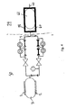
- the device comprises a storage compartment 1, in which the medication is contained.
- the storage compartment 1 is made as a sealed bag with an outlet 3, through which medication can be discharged from the bag simply by adding a force external to the sides of the bag.
- the compartment 1 is surrounded by an elastomere pressure jacket 2, which will apply a nearly constant force to the compartment, until being empty of medication.
- the pressure of the medication at the outlet 3 is hereby held constant, until the compartment 1 is emptied for medication.
- the outlet 3 is in connection with an outlet 4 from the device, from where the medication is administered e.g. infused.
- the outlet 4 is in fluid communication with the compartment 1 over two individual communications 5 and 6, each having a valve 7 and 8 and a capillary 9 and 10.
- the capillary 9 has a small diameter, which will correspond to a low rate of discharge of medication, referred to as the basal rate. For diabetic patients this corresponds to the low rate of insulin discharge, which will balance the glucose level under normal conditions between meals. Adjustment of rate of discharge through capillary 9 can take place by adjustment of the valve 7.
- the valve 7 may be controlled between a fully open and a fully closed position, like a pulse modulation with adjustable duty rate in a fixed duty cycle. A high duty rate will then correspond to a high rate of discharge, however still within the basal rate.
- the capillary 10 in communication 6 has a diameter larger than the diameter of the capillary 9.
- the capillary 10 is able to discharge medication at a rate referred to as the bolus rate.
- the bolus rate For diabetic patients this corresponds to the high rate of insulin discharge, which will balance the glucose level during and right after meals.
- Adjustment of rate of discharge through capillary 10 can take place by adjustment of the valve 8.
- the valve 8 may be controlled between a fully open and a fully closed position, like a pulse modulation with adjustable duty rate in a fixed duty cycle. A high duty rate will then correspond to a high rate of discharge, and a low duty rate to a low rate of discharge, however still within the bolus rate.
- valve 7 In case of a valve failure of valve 7, causing the valve to jam in open position, the control of the basal rate will be lost. This may, related to infusion of insulin, cause a slightly over dosing of insulin between the meals, but will have no harmful effect on the diabetic patient. If the failure however was on valve 8, still jam in open position, the bolus rate of discharge will have a deadly effect on the diabetic patient.
- the communication 6 comprises a separate capillary 11, which will restrict the rate of discharge from compartment 1 through communication 6 to outlet 4, in case the valve 8 is jam in open position.
- the effect of the valve 8 being jam in open position will now be an uncontrolled bolus rate of discharge, but restricted to a low value.
- the capillary 11 may restrict the rate of discharge to a value correspond to the normal bolus infusion over a day, if this was to be infused continuously.
- valve 8 Under normal operation of the communication 6, valve 8 will be closed for a long period between the meals. In this period medication discharge from compartment 1, through capillary 11 to compartment 12, which is a small sealed bag in fluid communication with compartment 1, and with an elastomere pressure jacket 13, surrounding the compartment 12.
- This compartment 12 with pressure jacket 13 is referred to as a holding device, and works as an accumulator in hydraulic systems.
- the pressure in compartment 1 and compartment 12 will equalise during the close period for valve 8, and as valve 8 is opened the bolus rate of discharge will be high, as only capillary 10 restricts the rate of discharge from compartment 12 to outlet 4 in fig. 1 .
- a valve failure will an uncontrolled rate of discharge as result, but the rate of discharge will be restricted to a normal level of infusion over a day.
- the patient might feel a slightly uncomfortably, but will in no way be harmed by the valve failure.
- the device of fig. 1 is a wet disposable device, containing the medication in fluid form (e.g. insulin), the tubing, the capillaries, the valves and the holding device.
- the wet disposable device may contain other needed elements of the infusion device, such as actuating means for the valves and the elastomere pressure jackets.
- the wet device is disposable, all elements, which are not in direct contact with the medication, could be contained in a control device, and the control device and the wet device could connected in a way that makes reuse of the control device possible. As only the wet device is part of this invention, the control device shall not be further described.
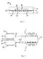
- fig. 2 is shown a infusion device similar to the device of fig. 1 .
- each of the capillaries 9 and 10 are divided into two series connected capillaries, 9a, 9b and 10a, 10b respectively. Except from 9a, 9b, 10a and 10b all reference numbers from fig. 1 apply to to fig. 2 .
- the two series connected capillaries, 9a, 9b and 10a, 10b, of fig. 2 are each supplied with a detection device 14 and 15.
- the detection devices 14 and 15 are identical, and only detection device 14 is to be explained in details.
- connection 16 is in fluid communication with compartment 19 in the detector device 14, see fig. 3 , the connection 17 with compartment 20 and the connection 18 with compartment 21.
- the compartments 19-21 are formed by lamination of to parts 22 and 23, with deflectable membranes 24 and 25 between.
- the structure of the surface of each of the two parts is, on the side facing the membranes 24 and 25, such that the compartments 19-21 will be formed as the lamination has taken place.
- Each membrane 24 and 25 is able to deflect upwards, indicated as position 26, or downwards, indicated as position 27.
- Detection means is able to detect between even position, upward position and downward position, and able to detect on each membrane separately. This detection means could simply be an optical detector, which sees the direction of a deflection. A normal infusion will have a pressure drop between compartment 19 and 20, and between compartment 20 and 21, as result. Normal infusion will therefore be detected as an upward deflection of membrane 24 and a downward deflection of membrane 25.
- the communications 5 and 6 of figs. 1 and 2 consists of fluid channels, by which the storage compartment communicates with capillaries and valves.
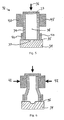
- the valves 7 and 8 have the purpose of blocking one such fluid channel, which is shown at figs. 5 and 6 .
- the valves which are provided according to the second aspect of the present invention, are used in embodiments according to the first aspect of the invention.
- the valve 32 of fig. 5 is formed as a block, which is placed over a fluid channel 33, made by removing of material from a solid block 34 or by mounding a block 34 with the channel 33.
- This solid block 34 is an infusion manifold of the infusion device of figs. 1 or 2 .
- a membrane 35 Between the solid block 34 and the valve block 32 is provided a membrane 35, which is able to deflect into the fluid channel 33. This deflection is indicated at fig. 6 .
- the valve block 32 is held against the solid block 34 by a force 36, which is acting on a solid material part 37.
- the valve member 38 is formed by a soft elastomere, contained within a case of a hard but deformable elastomere 39.
- the hard elastomere 39 is held in shape by a solid ring member 40 at the lower end, and by a moveable ring member 41 at the upper end.
- a force 42 is applied to the ring member 41, the hard elastomere 39 is deformed, and the soft elastomere 38 is pressed towards the membrane 35 and into the fluid channel 33. Fluid passage is hereby prevented, as the valve member is closed.
- fig. 7 an infusion device like that of fig. 2 is shown, but with the medication contained in two compartments, 1a and 1b.
- Each of the two compartments 1a and 1b are supplied with a elastomere pressure jacket 2a and 2 b, and have a separate outlet 3a and 3b.
- the medication discharged from outlet 4 through communication 5 can hereby be different from the medication discharged from outlet 4 through communication 6.
- the basal rate of infusion could be with one type of insulin
- the bolus rate of infusion could be with a more power full or with a faster acting type of insulin, whereby a detected drop in the glucose level for the patient quickly could be compensated with infusion of a bolus rate.
- the device may comprise a separate container 28 for storage and supply of a medication in fluid form.
- Said container may comprise a fluid chamber 60 and a medication chamber 61 being arranged relatively to each other so that when volume of the fluid chamber 60 increases the volume of the medication chamber 61 decreases.
- the container may comprise any feature or element of the second aspect of the present application.
- the container 28 may be arranged downstream at least one restricting means (9-11) and upstream the outlet means 62. In the preferred embodiment the container 28 is arranged downstream all the restricting means (9-11) and upstream the outlet means (62).
- Fig. 4 shows the overall infusion device of the invention, having a storage compartment 61 for medication, and being in connection with an outlet 4 from the device, is shown.
- the storage compartment 1 is made as a sealed bag with an outlet 3, where the medication can be discharged from the bag simply by adding a external force to the bag. This external force is applied by pressurising the container 28.
- the device may comprise a separate container for storage and Supply of a medication in fluid form.
- Said container may comprise a fluid chamber and a medication chamber being arranged relatively to each other so that when volume of the fluid chamber increases the volume of the medication chamber decreases.
- the container may comprise any feature or element of the second aspect of the present application.
- the container may be arranged downstream at least one restricting means and upstream the outlet means. In one embodiment the container may be arranged downstream all the restricting means and upstream the outlet means. In the latter embodiment the fluid chamber may be in fluid communication with any restricting means and outlet means may be in communication with the medication chamber.
- Position 30 indicates the part of the infusion device for pressurising the container 28, and is the device shown in fig. 2 .
- the fluid in compartment 31 is not a medication, but a suitable fluid for pressurising the container 28 e.g. a saline solution.
- a suitable fluid for pressurising the container 28 e.g. a saline solution.
- the function of device part 30 is similar to that of fig. 2 , and shall therefore not be described further.
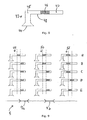
- Fig. 8 shows an alternative pressure detecting device 43 to that of fig. 3 .
- a membrane 44 seals a pipe-shaped element 48, whereby a closed compartment inside the pipe-shaped element exists.
- One part 45 of the closed compartment is filled with a liquid, and another part 47 is filled with air.
- a plunger element 46 seals the air-part 47 from the liquid part 45, and pressure acting on the membrane 44 will thus move the plunger element 46, until a force equilibrium between membrane 44 and air-part 47 arises. Detecting the movement of the plunger element 46 will therefore correspond to detecting the pressure acting on the membrane.
- the air-part 47 could be formed by a sealed bellow, whereby leaking of air into the liquid-part 45 is prevented. It could also be formed simply by a spring element, whereby only leaking of liquid into the spring-part 47 is to be prevented. Of importance is only that liquid-part 45 is movable within certain limitations.
- the plunger element could be a second liquid, with different colour than and not miscible with the liquid-part 45.
- the interface between the two liquids detectable, and will move due to pressure variations on the membrane 44.
- a sealing element between liquid-part 45 and air-part 47 will however still be needed, as totally filling of the pipe-shaped element 48 with liquid will make moving of the interface impossible.
- Fig. 9 indicates in picture A to E different detections results by use of the pressure detection device of fig. 8 .
- the infusion communication 5, with the restricting element 9a and 9b, is supplied with a total of three pressure detectors 43, indicated as detector 49, 50 and 51.
- the detections results will hereby be: Pictur e Detector 49 Detector 50 Detector 51 situatio n A Centred Centred Left No flow B Right Centred Left 9a blocked C Right Right Left 9b blocked D Right Right Right Back pressure E Right Right Centred Normal flow.
Abstract
Description
- The present invention relates to a device for administering a medication and more specifically to a safe construction for administering a medication in fluid form and in particular to a device for administering a medication with a sensitive structure. Furthermore the present invention is a device as defined in the claims.
- Administering systems for continuous administering of a medication in fluid form are known in the art, and used in hospitals. The purpose for such devices is to give the patient the freedom of movement, even though he is connected to a device for administering of a medication e.g. by infusion. The adjustment of the rate of discharge from such devices takes place only by adjusting the dosage by hand, and is done by the personnel at the hospital as a part of the treatment of the patient.
- Administering systems for controlled administering of fluid based medication, outside hospitals is also known in the art such as in
EP-A-39124 - It may be an object of a preferred embodiment of the present invention to provide a device for continuous administering of fluid based medication, wherein the administering is controllable, and where the infusion during any fault situation in the device is unable to harm the patient.
- A further object of a preferred embodiment of the present invention may be to provide a device which may be able to administer medication in two types of doses - a basal dose and a bolus dose. Furthermore it may be an object of a preferred embodiment of the present invention to provide a device wherein the flow of medication in the device may be monitored.
- According to a first aspect the present invention relates to a device according to
claim 1 for administering of a medication in fluid form, said device comprising an outlet means and a storage means for storage of a fluid, said device further comprising, - two individual communications each of which being in fluid communication with the storage means and the outlet means,
- each communication comprising at least one flow restricting means,
- at least one valve means arranged down stream the storage means and upstream at least one flow restricting means, and
- As the medication to be administered may have a molecule structure which is so fragile that it may not be passed through the restricting means the device may comprise a separate container for storage and supply of a medication in fluid form. Said container may comprise a fluid chamber and a medication chamber being arranged relatively to each other so that when volume of the fluid chamber increases the volume of the medication chamber decreases, the medication chamber and the fluid chamber preferably being separated by a membrane. The container may comprise any feature or element of the second aspect of the present application.
- It is desirable that the fluids on each side of the membrane are not in fluid connection. Thus the membrane may define a seal between a supply-side-chamber and a discharge-side-chamber. The supply-side-chamber and/or the discharge-side-chamber may be part of the detection means. In some embodiments the discharge-side-chamber of a first detection means may be a supply-side-chamber of a second detection means or vice versa. In order to determine the pressure difference between the two chambers, the membrane may comprise an elastic material. Such a material may comprise a natural rubber material and/or a synthetic rubber material.
- The container may be arranged downstream at least one restricting means and upstream the outlet means. In one embodiment the container may be arranged downstream all the restricting means and upstream the outlet means. In the latter embodiment the fluid chamber may be in fluid communication with any restricting means and outlet means may be in communication with the medication chamber.
- An advantage of the above mentioned container may be seen as eliminating any passing of the medication through a restricting means. Thus any other fluid e.g. a saline solution may be used to pressurise the medication chamber of the container.
- The fluid of the device may contain a medication or may be any other fluid such as a saline solution. The device may be adapted to restrict the rate at which a medication is administered e.g. discharged thought the outlet of the device. The outlet may be connected to a cannula or tube connected to a cannula.
- At least a part of the device may be adapted to be positioned in a body of a mammal e.g. a human being, for shorter or longer period. In some embodiments only a cannula is placed in the human body and the rest of the device is placed outside the body. In some embodiments the storage means may be adapted for accommodation in a human body and thus refilling of the storage means may be done by means of a needle inserted through the skin of the human being or mammal.
- The medication comprised in the fluid may be insulin or hormones or an anti-inflammatoric medication. The two communications may be in individual fluid communication with the storage means and the outlet means. In some embodiments a part of each of the two communications may be provided by the same tube such that said tube branch out into two separate communications. The two communications may branch out and merge in different locations on the individual communications.
- The restricting means may be provided by small tubes e.g. capillaries adapted to restrict the flow. In an embodiment all restriction means are provided as capillaries. The capillaries may have different internal diameters so as to allow different flow rates. In an embodiment at least one of the capillaries is provided by a piezo electric element adapted to change the internal diameter such that the flow rate of said capillary may be varied. Such a piezo electric element may be annular.
- The cross-sectional area of at least one of the capillaries may be between 10 µm2 and 50 µm2, such as between 15 µm2 and 30 µm2, such as 20 µm2. The length of the capillaries may be used to design the desired pressure drop over the capillay. Thus the small capillaries of the present invention e.g. the capillary used for the basal dose, may have a length of between 30 mm and 100 mm, such as between 40 mm and 80 mm, such as between 50 mm and 70 mm, such as 66 mm. In order to reduce the physical extend of the capillary the capillary may be U-shaped or define any other shape reducing the physical extend of the capillary.
- The length of the larger capillary e.g. the capillary upstream the holding means may be 3-10 times shorter than the aforementioned capillary, such as between 5 and 8 times shorter. The length of the capillary may be adapted to the individual which is to use the device. The size of the capillary may be chosen with regard to data of the person such as size, weight, metabolism, the average size of means eaten be the person etc.
- In an embodiment the capillaries may be provided in units of 10 mm such that joining the capillaries in series may provide a desired length. Thus the ends of units may be adapted of attachment to each other. According to the first aspect of the invention the capillaries and the valve means may be provided in a surface of a substrate comprising silicon. Thus the first and/or the second individual communication may be provided in the silicon substrate.
- The system preferable comprises one valve. The valve may be arranged in one of the two communications or a valve may be provided in each of the two communications. By providing a valve it may be possible to control the administering of medication even more precisely as the flow in one or both of the individual communications may be shut off and turned on in any desired pattern.
- In the present application a restricting means is defined as a means for restricting the flow rate. A restricting means may vary the flow rate and thus be adjustable.
- In the present application a valve means is defined as a means which is able to shut off the flow completely. Thus a valve may be set in any position between two opposite positions, the open position and the closed position. I.e. the valve may be set in any intermediate position. A valve may thus be seen as a restricting means which can be shut off.
- In the present invention a communication is defined as any path wherein a fluid may flow.
- At least one of the individual communications comprises a holding means. Said holding means may be adapted to store a predetermined amount of medication of fluid such that a larger dose of medication or fluid may be administered. In some embodiments both the individual communications may comprise separate holding means such that the two communications may be used for administering a larger dose. Thus if the two individual communications comprises different types of medications larger doses of each of the two medications may be administered individually. As an example one of the two communications may be in fluid connection with fluid comprising insulin while the other communication is in fluid communication with a glucose solution. Should an overdose of insulin be administered the holding member of the communication comprising glucose may be used to eliminate the undesired effects to the overdose. The two communications may comprise any dope and anti-dope.
- The device may comprise means for pressurising said storage means. Such means may be an elastic member provided around the storage means. In other embodiments the means for pressurising may be provided as electrically actuated actuation means or a pressure compartment adapted to apply a pressure on the storage means.
- It may be desirable to be able to monitor the administering of medication. Thus at least one of said restricting means may comprise detection means adapted to supervise the flow in the restricting means. The detection means may be an impeller or any other device for supervising a flow. In an embodiment the detection means may be adapted to detect a pressure difference between a supply-side and a discharge-side of the restricting means.
- The supply-side may in some embodiments be seen as directly at the inlet, while in other embodiments the supply-side may be seen as an area in the vicinity of the inlet. In yet other embodiments the supply-side may be seen as anywhere between the inlet and another element in the communication e.g. the first upstream element.
- The discharge-side may in some embodiments be seen as directly at the outlet, while in other embodiments the discharge-side may be seen as an area in the vicinity of the outlet. In yet other embodiments the discharge-side may be seen as anywhere between the outlet and another element in the communication e.g. the first downstream element.
- In some embodiments only some of the restricting means are provided with a detecting means whereas in other embodiments all restricting means are provided with detection means.
- As the flow is monitored it may be possible for a control means to monitor the amount of medication or fluid which is administered.
- The detection means may comprise a membrane adapted to move between a first position and a second position, each side of said membrane may be in fluid communication with an inlet and/or an outlet of a restricting means. Thus the position of the membrane may be used as an indicator for the pressure difference between the first and the second position.
- In some embodiments at least one of the detection means may be arranged such that the pressure difference over two restricting means and/or valves may be determined. In other embodiments each detecting means may be in fluid communication with a supply-side and a discharge-side of one of the restricting means, such that the pressure difference over one restricting means is determined.
- In one embodiment the two individual communications may define a first and a second communication and wherein the first communication may be adapted for administering of a basal rate medication and the second communication may be adapted for administering of a bolus rate of medication. As the second communication is adapted for dosing of a bolus rate of medication it may comprise the holding means. Thus while the valve is closed the holding means may be filled up and as a restricting means may be provided upstream the holding means the filling rate may be low. When the valve is opened and the holding means is emptied the bolus rate of medication may be administered.
- The holding means may comprise a chargeable accumulator adapted to be charged with fluid.
- At least one of the aforementioned valve means may comprise:
- a passage defined by at least a first element and a second element,
- In an embodiment of the first aspect of the present application the device may further comprise control means adapted to control the administering of medication. Such a control means may comprise a first computer system, the computer system comprising input means for collecting data in a first format, processing means for processing the data, output means for presenting data in a second format, and data storage means having stored therein a computer program.
- The computer system may comprise an operating system. The data collected in the first format may be data form the detection means indication weather or not the flow in the system is according to the specification. The data in the first format may be information e.g. provided by the user, about administering of the bolus rate and/or the basal rate.
- The data in the second format may be an alarm signal indicating that one of the restricting means and/or one of the valves is out of order. The data in the second format may be control information used to control the valve and/or the holding means. Accordingly in some embodiments the control means may be adapted to control the storage means and/or the holding means and/or at least one valve of the device for administration.
- The control means may by operable by means of a separate control unit in wired and/or wireless connection with the device.
- The computer program may be adapted to perform the steps of:
- a opening of the valve means in the second communication
- applying a pressure on the holding means so as to administer the bolus rate
- closing the valve means in the second communication.
- Furthermore the computer program may be adapted to remove the pressure on the holding means, so as to allow said means to be filled with a new bolus rate.
- Medication may be infused at a rate controlled by one of the two communications, and the holding means may give the possibility of infusing a bolus rate of medication for a short period. The continuously rate of infusion the device is able to discharge, in case of all control are lost, is balanced to the patient, whereby the worst case fault situation is unable to harm the patient.
- The restricting means of the infusion device may be supplied with detection means, supervising the infusion of medication. Hereby may be achieved that the control system receives information to evaluate the infusion situation, and hereby may be able to detect an infusion failure.
- In a specific embodiment of the invention, a membrane may form the detection means, where each side of the membrane may be in fluid communication with each side of the restricting means. Hereby may be achieved that the direction of the deflection of said membrane may indicate the direction of pressure over said restricting means.
- In another specific embodiment of the invention, separate pressure detectors may form detection means, each may be in pressure communication with supply side or discharge side of one of said restricting means. Hereby is achieved that the pressure detection can take place locally in the infusion communication pad, without any additional fluid communications being needed.
- A membrane on the detecting means may seal a closed area comprising liquid, and an elastic element may give the membrane and the liquid the possibility of moving in accordance with a pressure rise on the side of the membrane facing away from said liquid, and the movement of liquid may be detectable. Hereby may be achieved that the medication may be kept inside the infusion communication, and only the pressure may be transported, via the membrane, to the liquid. This gives access to different ways for detecting the movement of the liquid, as no considerations regarding the impact from the medications itself has to be taken, besides from the choose of membrane material.
- In a further specific embodiment, capillaries may form the restricting means in the infusion device. Hereby may be achieved that the rate of infusion may be well defined in relation to the pressure acting on each side of a restricting means.
- The infusion device may contain storage means for medication, this storage means for medication may be pressurised by fluid from a separate part of the infusion device, whereby the rate at which medication discharge through the outlet means may depend on the rate at which fluid pressurise the storage means for medication. Hereby may be achieved that the medication may be infused directly from the storage compartment to the outlet of the infusion device, without passing any valves and restricting means. For sensitive medications this could be of advantage.
- In a specific embodiment of the invention, one of the two individual communications may restrict the rate at which medication from one storage means for medication discharges, and the other of the two individual communications may restrict the rate at which medication from another storage means for medication discharge. Hereby may be achieved that medication of different strength or different response time may be discharged from the device.
- It may be seen as an advantage that the two individual communications may form a first communication for basal rate of infusion of medication and a second communication for bolus rate of infusion of medication, and where the holding means may be contained in the second communication. The medication may hereby able to infuse at controlled rates, depending on the actually and present need.
- The device for infusion of medication in general contains:
- storage means for storage of fluid,
- outlet means for infusion of medication,
- means for pressurising said storage means,
- means for restricting the rate at which medication discharge through said outlet means,
- valve means disposed intermediate said storage means and said restricting means,
- Said restricting means may be supplied with detection means, whereby infusion of medication is supervised.
- Said detection means may be formed by a membrane, each side of said membrane being in fluid communication with each side of said restricting means, whereby the direction of the deflection of said membrane will indicate the direction of pressure over said restricting means.
- The separate pressure detectors may form said detection means, each in pressure communication with supply side or discharge side of one of said restricting means.
- A membrane may seal a closed area containing liquid, and that an elastic element may give said membrane and said liquid the possibility of moving in accordance with a pressure rise on the side of the membrane facing away from said liquid, said moving of liquid being detectable.
- Said restricting means may be formed by capillaries.
- Said fluid in said storage means may be the medication.
- The device may contain storage means for medication, said storage means for medication being pressurised by fluid from said storage means for fluid, whereby the rate at which medication discharge through said outlet means may depend on the rate at which fluid pressurise said storage means for medication.
- One of said two individual communication may restrict the rate at which medication from one storage means for medication discharges, and the other of said two individual communication may restrict the rate at which medication from another storage means for medication discharge.
- Said two individual communications may form a first communication for basal rate of infusion of medication and a second communication for bolus rate of infusion of medication and where said holding means may be contained in said second communication.
- Said holding means may form a chargeable accumulator, charge with fluid from said storage means over said separate restricting means; while said valves means in second communication is closed.
- An opening of said valve means in said second communication may allow said holding means to perform said bolus rate of infusion of medication, while said holding means depressurise through said valve means in second communication, where after the rate of infusion of medication in said second communication may drop to a lower level controlled by said separate restricting means.
- Said valve means may be formed by an elastomere material, which actuation from an actuator will deform into a part of said communication, whereby flow of fluid may be prevented.
- An embodiment of the present invention relates also to a flow regulating device comprising:
- a passage defined by at least a first element and a second element,
- In some embodiments the first element is a primary deformable element, while in others the second element is a primary deformable element. Yet in other embodiments both the first and the second elements are primary deformable elements. In the latter case a half circle may be defined in both the elements such that the two half circles together define a circle. When the two elements are deformed the cross-sectional area of the circle may be deformed.
- The primary deformable elements may be adpated to be changed between two positions a first position wherein the cross-sectional area is as big as possible and a second position wherein the cross-sectional area is as small as possible e.g. close to zero.
- In an embodiment at least a part of the primary deformable element in the first position encircles at least a part of the passage.
- When force is applied to the deformable element, the element may change from the first position to the second position or any intermediate position. Thus the force applied to the deformable element may be used to control the cross-sectional area of the passage.
- In some embodiments a force in the direction of the centre of the passage may be applied in order to change the cross-sectional area of said passage. In other embodiments forces may applied on two sides of the primary deformable element. A force zone may then be defined between the forces and in some embodiments the passage may not be defined in the force zone. Thus the primary deformable element may be deformed in a first direction when a force is applied in a second direction, the first direction being transverse to the second direction.
- A secondary deformable element may encircle the primary deformable element. The secondary deformable element may be harder than the primary deformable element. Thus the secondary deformable element may be adapted to work as an outer wall of the primary element. The secondary deformable element may in some embodiments be hard enough to retain its shape without any support from other elements. In other embodiments the secondary deformable element may not be hard enough to retain its shape without any support and therefore a supporting element may be provided around the second deformable element. The softer the primary element is the easier it may be for the element to block the passage. In some embodiments the primary deformable element may be an oil or water or air. In some embodiments the primary and/or the secondary element may comprise an elastomere e.g. silicone. When choosing the elastomere it is essential that the elastomere and the medication may work together without damaging each other.
- A membrane may be provided between the first and the second element. Such a membrane may be adapted to provide a seal such that the primary element and/or the secondary element may not come in contact with the content of the passage e.g. a medication on fluid form. Thus the membrane may provide a seal between the first and the second element. The membrane may comprise a natural rubber material and/or a synthetic rubber material.
- The area of the passage may be between 0,1 mm2 and 1 mm2, such as between 0,2 mm2 and 0,7 mm2, such as between 0,25 mm2 and 0,5 mm2. It may be desirable to choose a cross-sectional area at any place of the individual communications, which is as small as possible as the total volume in the two individual communications may then be limited. The smaller the total volume of the individual communications is the easier it may be to control the system. On the other hand the cross-sectional areas may not be so small that the resistance in the system is too big. Only in the restricting means the resistance may be desired to be small.
- A device may be provided in which a valve means may be formed by an elastomere material, which under actuation from an actuator may deform into a part of said communication, whereby flow of fluid may be prevented.
- The system comprises a container for storage and supply of a medication in fluid form, said container comprising a first and a second chamber being arranged relatively to each other so that when volume of the first chamber increases the volume of the second chamber decreases.
- In an embodiment the first chamber and the second chamber are interconnected by a hydraulic system e.g. comprising a saline solution. Thus the hydraulic liquid may be used to change the volumes of the two chambers e.g. by moving pistons in each chamber.
- Furthermore at least a part of a sidewall separating the first and second chamber may movable. Thus in one embodiment only one wall separates the first and the second chamber and said wall may work as a piston.
- In other embodiments at least a part of a sidewall separating the first and second chamber may be flexible. Thus a bag-like element defining the secondary chamber may be provided in a large chamber. The part of the large chamber, which is not filled with the bag-like element, may define the primary chamber. When the primary chamber is filled with a fluid the secondary chamber in the bag-like element collapses and fluid in the bag may be administered. In some embodiments the bag-like element defines the primary chamber and the rest of the large chamber defines the secondary element.
- The first chamber may be a fluid chamber adapted for storage of a fluid e.g. a saline solution and the second chamber may be a medication chamber for storage of medication. The saline solution may be an isotonic solution which does not change the balance of salts on the blood.
- In general it may be seen as an advantage to choose elements and fluids which does not damage each other and which may be inserted or administered in the human body.
- An embodiment of the invention will now be described in details with reference to the drawing in which:
-
Fig. 1 shows a device according to the first aspect of the invention, -
Fig. 2 shows a device for administering of medication comprising flow detectors, -
Fig. 3 shows a flow a flow detector according to the first aspect of the invention, -
Fig. 4 shows a principal embodiment of the invention, where the medication itself is contained separate from the infusion control system, -
Figs. 5 and 6 show a flow regulating device according to the second aspect of the invention, -
Fig. 6 shows a detailed view of an embodiment of a valve for the infusion control system, shown in closed position, -
Fig. 7 shows an embodiment wherein medication is discharged from two separate compartments, -
Fig. 8 shows a embodiment of a pressure detection means, and -
Fig. 9 A principal view of a flow detector, showing different possible detecting results in picture A-E. - In
fig. 1 is shown an infusion device for administering of medication in fluid form, e.g. infusion of insulin to a diabetic patient. The device comprises astorage compartment 1, in which the medication is contained. Thestorage compartment 1 is made as a sealed bag with anoutlet 3, through which medication can be discharged from the bag simply by adding a force external to the sides of the bag. - The
compartment 1 is surrounded by anelastomere pressure jacket 2, which will apply a nearly constant force to the compartment, until being empty of medication. The pressure of the medication at theoutlet 3 is hereby held constant, until thecompartment 1 is emptied for medication. Theoutlet 3 is in connection with anoutlet 4 from the device, from where the medication is administered e.g. infused. - The
outlet 4 is in fluid communication with thecompartment 1 over twoindividual communications capillary 9 and 10. The capillary 9 has a small diameter, which will correspond to a low rate of discharge of medication, referred to as the basal rate. For diabetic patients this corresponds to the low rate of insulin discharge, which will balance the glucose level under normal conditions between meals. Adjustment of rate of discharge through capillary 9 can take place by adjustment of the valve 7. In some embodiments the valve 7 may be controlled between a fully open and a fully closed position, like a pulse modulation with adjustable duty rate in a fixed duty cycle. A high duty rate will then correspond to a high rate of discharge, however still within the basal rate. - The capillary 10 in
communication 6 has a diameter larger than the diameter of the capillary 9. Thus the capillary 10 is able to discharge medication at a rate referred to as the bolus rate. For diabetic patients this corresponds to the high rate of insulin discharge, which will balance the glucose level during and right after meals. Adjustment of rate of discharge throughcapillary 10 can take place by adjustment of the valve 8. In some embodiments the valve 8 may be controlled between a fully open and a fully closed position, like a pulse modulation with adjustable duty rate in a fixed duty cycle. A high duty rate will then correspond to a high rate of discharge, and a low duty rate to a low rate of discharge, however still within the bolus rate. - In case of a valve failure of valve 7, causing the valve to jam in open position, the control of the basal rate will be lost. This may, related to infusion of insulin, cause a slightly over dosing of insulin between the meals, but will have no harmful effect on the diabetic patient. If the failure however was on valve 8, still jam in open position, the bolus rate of discharge will have a deadly effect on the diabetic patient.
- In order to prevent the bolus rate of discharge to be uncontrolled, the
communication 6 comprises aseparate capillary 11, which will restrict the rate of discharge fromcompartment 1 throughcommunication 6 tooutlet 4, in case the valve 8 is jam in open position. The effect of the valve 8 being jam in open position will now be an uncontrolled bolus rate of discharge, but restricted to a low value. The capillary 11 may restrict the rate of discharge to a value correspond to the normal bolus infusion over a day, if this was to be infused continuously. - Under normal operation of the
communication 6, valve 8 will be closed for a long period between the meals. In this period medication discharge fromcompartment 1, throughcapillary 11 tocompartment 12, which is a small sealed bag in fluid communication withcompartment 1, and with an elastomere pressure jacket 13, surrounding thecompartment 12. Thiscompartment 12 with pressure jacket 13 is referred to as a holding device, and works as an accumulator in hydraulic systems. The pressure incompartment 1 andcompartment 12 will equalise during the close period for valve 8, and as valve 8 is opened the bolus rate of discharge will be high, as only capillary 10 restricts the rate of discharge fromcompartment 12 tooutlet 4 infig. 1 . - A valve failure will an uncontrolled rate of discharge as result, but the rate of discharge will be restricted to a normal level of infusion over a day. The patient might feel a slightly uncomfortably, but will in no way be harmed by the valve failure.
- The device of
fig. 1 is a wet disposable device, containing the medication in fluid form (e.g. insulin), the tubing, the capillaries, the valves and the holding device. The wet disposable device may contain other needed elements of the infusion device, such as actuating means for the valves and the elastomere pressure jackets. As the wet device is disposable, all elements, which are not in direct contact with the medication, could be contained in a control device, and the control device and the wet device could connected in a way that makes reuse of the control device possible. As only the wet device is part of this invention, the control device shall not be further described. - In
fig. 2 is shown a infusion device similar to the device offig. 1 . Infig. 2 each of thecapillaries 9 and 10 are divided into two series connected capillaries, 9a, 9b and 10a, 10b respectively. Except from 9a, 9b, 10a and 10b all reference numbers fromfig. 1 apply to tofig. 2 . The two series connected capillaries, 9a, 9b and 10a, 10b, offig. 2 are each supplied with adetection device detection devices only detection device 14 is to be explained in details. - Flow of medication over capillary 9a will have a pressure drop as consequence, and this pressure drop is detected between
connection connection connection 16 is in fluid communication withcompartment 19 in thedetector device 14, seefig. 3 , theconnection 17 withcompartment 20 and theconnection 18 withcompartment 21. - The compartments 19-21 are formed by lamination of to
parts deflectable membranes 24 and 25 between. The structure of the surface of each of the two parts is, on the side facing themembranes 24 and 25, such that the compartments 19-21 will be formed as the lamination has taken place. - Each
membrane 24 and 25 is able to deflect upwards, indicated asposition 26, or downwards, indicated asposition 27. Detection means is able to detect between even position, upward position and downward position, and able to detect on each membrane separately. This detection means could simply be an optical detector, which sees the direction of a deflection. A normal infusion will have a pressure drop betweencompartment compartment membrane 24 and a downward deflection of membrane 25. - The table below indicates all possible detections results, and the situation leading to the result.
Membrane 24Membrane 25 Situation Even Even No flow Upward Even 9a blocked Downward Even Error Even Upward Back pressure Upward Upward Leak Downward Upward Back flow Even Downward 9b blocked Upward Downward Normal flow Downward Downward Error - The
communications figs. 1 and 2 consists of fluid channels, by which the storage compartment communicates with capillaries and valves. The valves 7 and 8 have the purpose of blocking one such fluid channel, which is shown atfigs. 5 and 6 . The valves, which are provided according to the second aspect of the present invention, are used in embodiments according to the first aspect of the invention. - The
valve 32 offig. 5 is formed as a block, which is placed over afluid channel 33, made by removing of material from asolid block 34 or by mounding ablock 34 with thechannel 33. Thissolid block 34 is an infusion manifold of the infusion device offigs. 1 or 2 . Between thesolid block 34 and thevalve block 32 is provided amembrane 35, which is able to deflect into thefluid channel 33. This deflection is indicated atfig. 6 . - The
valve block 32 is held against thesolid block 34 by aforce 36, which is acting on asolid material part 37. Thevalve member 38 is formed by a soft elastomere, contained within a case of a hard butdeformable elastomere 39. Thehard elastomere 39 is held in shape by asolid ring member 40 at the lower end, and by amoveable ring member 41 at the upper end. As aforce 42 is applied to thering member 41, thehard elastomere 39 is deformed, and thesoft elastomere 38 is pressed towards themembrane 35 and into thefluid channel 33. Fluid passage is hereby prevented, as the valve member is closed. - In
fig. 7 an infusion device like that offig. 2 is shown, but with the medication contained in two compartments, 1a and 1b. Each of the two compartments 1a and 1b are supplied with aelastomere pressure jacket 2a and 2 b, and have aseparate outlet 3a and 3b. The medication discharged fromoutlet 4 throughcommunication 5 can hereby be different from the medication discharged fromoutlet 4 throughcommunication 6. For diabetic patient, the basal rate of infusion could be with one type of insulin, and the bolus rate of infusion could be with a more power full or with a faster acting type of insulin, whereby a detected drop in the glucose level for the patient quickly could be compensated with infusion of a bolus rate. - In
figs. 1, 2 and7 an infusion device where the medication itself is forced through capillaries, valves and pressure variations has been shown. Some medications consist of molecules with a very sensitive structure, i.e. insulin. Those medications may be too sensitive to cope with the influences from the infusion device offigs. 1 and 2 . - As the medication to be administered may have a molecule structure which is so fragile that it may not be passed through the restricting means the device may comprise a
separate container 28 for storage and supply of a medication in fluid form. Said container may comprise afluid chamber 60 and amedication chamber 61 being arranged relatively to each other so that when volume of thefluid chamber 60 increases the volume of themedication chamber 61 decreases. The container may comprise any feature or element of the second aspect of the present application. - The
container 28 may be arranged downstream at least one restricting means (9-11) and upstream the outlet means 62. In the preferred embodiment thecontainer 28 is arranged downstream all the restricting means (9-11) and upstream the outlet means (62). -
Fig. 4 shows the overall infusion device of the invention, having astorage compartment 61 for medication, and being in connection with anoutlet 4 from the device, is shown. Thestorage compartment 1 is made as a sealed bag with anoutlet 3, where the medication can be discharged from the bag simply by adding a external force to the bag. This external force is applied by pressurising thecontainer 28. - As the medication to be administered may have a molecule structure which is so fragile that it may not be passed through the restricting means the device may comprise a separate container for storage and Supply of a medication in fluid form. Said container may comprise a fluid chamber and a medication chamber being arranged relatively to each other so that when volume of the fluid chamber increases the volume of the medication chamber decreases. The container may comprise any feature or element of the second aspect of the present application.
- The container may be arranged downstream at least one restricting means and upstream the outlet means. In one embodiment the container may be arranged downstream all the restricting means and upstream the outlet means. In the latter embodiment the fluid chamber may be in fluid communication with any restricting means and outlet means may be in communication with the medication chamber.
- Controlling the pressure in the
container 28 controls the rate of infusion of medication fromcompartment 1, and medication is therefore only contained in a small part of the infusion device, this part being indicated asposition 29.Position 30 indicates the part of the infusion device for pressurising thecontainer 28, and is the device shown infig. 2 . The fluid incompartment 31 is not a medication, but a suitable fluid for pressurising thecontainer 28 e.g. a saline solution. Apart from that, the function ofdevice part 30 is similar to that offig. 2 , and shall therefore not be described further. -
Fig. 8 shows an alternative pressure detecting device 43 to that offig. 3 . Amembrane 44 seals a pipe-shapedelement 48, whereby a closed compartment inside the pipe-shaped element exists. Onepart 45 of the closed compartment is filled with a liquid, and anotherpart 47 is filled with air. Aplunger element 46 seals the air-part 47 from theliquid part 45, and pressure acting on themembrane 44 will thus move theplunger element 46, until a force equilibrium betweenmembrane 44 and air-part 47 arises. Detecting the movement of theplunger element 46 will therefore correspond to detecting the pressure acting on the membrane. - The air-
part 47 could be formed by a sealed bellow, whereby leaking of air into the liquid-part 45 is prevented. It could also be formed simply by a spring element, whereby only leaking of liquid into the spring-part 47 is to be prevented. Of importance is only that liquid-part 45 is movable within certain limitations. - The plunger element could be a second liquid, with different colour than and not miscible with the liquid-
part 45. Hereby is the interface between the two liquids detectable, and will move due to pressure variations on themembrane 44. A sealing element between liquid-part 45 and air-part 47 will however still be needed, as totally filling of the pipe-shapedelement 48 with liquid will make moving of the interface impossible. -
Fig. 9 indicates in picture A to E different detections results by use of the pressure detection device offig. 8 . Theinfusion communication 5, with the restricting element 9a and 9b, is supplied with a total of three pressure detectors 43, indicated asdetector Pictur e Detector 49 Detector 50Detector 51Situatio n A Centred Centred Left No flow B Right Centred Left 9a blocked C Right Right Left 9b blocked D Right Right Right Back pressure E Right Right Centred Normal flow.
Claims (20)
- Device for administering of a medication in fluid form, said device comprising an outlet means (4) and a storage means (31) for storage of a fluid, said device further comprising,- two individual communications (5, 6) each of which being in fluid communication with said storage means (31) and said outlet means (4),- each communication comprising at least one flow restricting means (9, 10, 11),- at least one valve means (7, 8) down stream the storage means and upstream at least one flow restricting means (9, 10, 11),wherein the device downstream of said communications (5, 6) further comprises a container (28) for storage and supply of a medication in fluid form, said container comprising a fluid chamber (60)and a medication chamber (61) being arranged relative to each other so that when volume of the fluid chamber increases then the volume of the medication chamber (1) decreases, and where at least one of said individual communications comprises a holding means (12) intermediate the storage means (31) and the valve means (8), said holding means (12) being in fluid communication with said storage means (31) over at least one restricting means (11).
- A device according to claim 1, wherein each of the two individual communications (5, 6) comprises at least one valve means (7, 8).
- A device according to any of claims 1-2, further comprising means (2) for pressurizing said storage means (31).
- A device according to any of claims 1-3, wherein at least one of said restricting means (9, 10) comprises detection means (14, 15) adapted to supervise the flow in the restricting means (9, 10).
- A device according to claim 4, wherein the detection means (14, 15) is adapted to detect a pressure difference between a supply-side and a discharge-side of the restricting means (9, 10).
- A device according to claim 1, wherein said holding means comprises a chargeable accumulator (13) adapted to be charged with fluid.
- A device according to any of the preceding claims, wherein at least one of the valve means (7, 8) comprises:- a passage (33) defined by at least a first element (38) and a second element (34),wherein at least one of the first (38) and second element (34) is adapted to be elastically deformed so as to change the cross sectional area of the passage (33).
- A device according to any of the preceding claims, further comprising control means adapted to control the administering of medication.
- A device according to claim 8, wherein the control means comprises- a first computer system with an operating system, the computer system comprising input means for collecting data in a first format, processing means for processing the date, output means for presenting data in a second format, and data storage means having stored therein a computer program.
- A device according to claim 8 or 9, wherein the control is adapted to control the storage means (31) and/or holding means (12) and/or at least one valve (7,8) of the device for administration.
- A device according to any of claims 8-10, wherein the control means is operable by means of a separate control unit.
- A device according to claim 11, wherein the control unit and the control means are adapted for wireless communication
- A device according to any of claims 8-12, wherein the computer program is adapted to perform the steps of:- an opening of the valve means (8) in the second communication (6)- applying a pressure on the holding means (12) so as to administer the bolus rate- closing the valve means (8) in the second communication (6).
- A device according to claim 1, where at least one of the valves (7, 8) is a flow regulating device comprising- a passage (33) defined by at least a first element (38) and a second element (34),wherein at least one of the first (38) and second element (34) is a primary deformable element adapted, when affected by a force in a first direction (42), to be elastically deformed in a second direction (36), so as to change the cross sectional area of the passage (33), said first direction (42) being transverse to said second direction (36).
- A device according to claim 14, wherein the primary deformable element is deformed when a force is applied to a side of said element.
- A device according to any of claims 14-15, wherein a secondary deformable element (39) encircles the primary deformable element.
- A device according to claim 16 , wherein the secondary deformable element is harder than the primary deformable element.
- A device according to claim 16, wherein the primary deformable element and/or the secondary comprises an elastomer.
- A device according to any of claims 14-18, further comprising a membrane (35) provided between the first (38) and the second element (34).
- A device according to any of claims 14-19, wherein the area of the passage (33) is between 0.1 mm2 and 1 mm2.
Priority Applications (1)
| Application Number | Priority Date | Filing Date | Title |
|---|---|---|---|
| EP08013595A EP2077130A3 (en) | 2002-02-18 | 2003-02-18 | Device for administering of medication in fluid form |
Applications Claiming Priority (5)
| Application Number | Priority Date | Filing Date | Title |
|---|---|---|---|
| DKPA200200240 | 2002-02-18 | ||
| DK200200240 | 2002-02-18 | ||
| DK200200970 | 2002-06-25 | ||
| DKPA200200970 | 2002-06-25 | ||
| PCT/DK2003/000107 WO2003068294A2 (en) | 2002-02-18 | 2003-02-18 | Device for administering of medication in fluid form |
Related Child Applications (1)
| Application Number | Title | Priority Date | Filing Date |
|---|---|---|---|
| EP08013595A Division EP2077130A3 (en) | 2002-02-18 | 2003-02-18 | Device for administering of medication in fluid form |
Publications (2)
| Publication Number | Publication Date |
|---|---|
| EP1476209A2 EP1476209A2 (en) | 2004-11-17 |
| EP1476209B1 true EP1476209B1 (en) | 2008-07-30 |
Family
ID=27735960
Family Applications (2)
| Application Number | Title | Priority Date | Filing Date |
|---|---|---|---|
| EP08013595A Withdrawn EP2077130A3 (en) | 2002-02-18 | 2003-02-18 | Device for administering of medication in fluid form |
| EP03706332A Expired - Lifetime EP1476209B1 (en) | 2002-02-18 | 2003-02-18 | Device for administering of medication in fluid form |
Family Applications Before (1)
| Application Number | Title | Priority Date | Filing Date |
|---|---|---|---|
| EP08013595A Withdrawn EP2077130A3 (en) | 2002-02-18 | 2003-02-18 | Device for administering of medication in fluid form |
Country Status (9)
| Country | Link |
|---|---|
| US (3) | US7517335B2 (en) |
| EP (2) | EP2077130A3 (en) |
| JP (1) | JP4002892B2 (en) |
| CN (2) | CN101380492B (en) |
| AT (1) | ATE402724T1 (en) |
| AU (1) | AU2003208305A1 (en) |
| DE (1) | DE60322512D1 (en) |
| RU (1) | RU2279898C2 (en) |
| WO (1) | WO2003068294A2 (en) |
Families Citing this family (49)
| Publication number | Priority date | Publication date | Assignee | Title |
|---|---|---|---|---|
| US20080172026A1 (en) | 2006-10-17 | 2008-07-17 | Blomquist Michael L | Insulin pump having a suspension bolus |
| EP3572106A1 (en) | 2003-04-23 | 2019-11-27 | Valeritas, Inc. | Hydraulically actuated pump for long duration medicament administration |
| US7351240B2 (en) * | 2004-05-28 | 2008-04-01 | Ethicon Endo—Srugery, Inc. | Thermodynamically driven reversible infuser pump for use as a remotely controlled gastric band |
| US7374565B2 (en) * | 2004-05-28 | 2008-05-20 | Ethicon Endo-Surgery, Inc. | Bi-directional infuser pump with volume braking for hydraulically controlling an adjustable gastric band |
| US9089636B2 (en) | 2004-07-02 | 2015-07-28 | Valeritas, Inc. | Methods and devices for delivering GLP-1 and uses thereof |
| WO2006037330A1 (en) * | 2004-10-08 | 2006-04-13 | Danfoss A/S | A pumping system and a method for controlling a fluid flow in a pumping system |
| US20090211657A1 (en) * | 2004-12-08 | 2009-08-27 | Danfoss A/S | Bubble-tolerant micro-mixers |
| WO2006131115A1 (en) * | 2005-06-04 | 2006-12-14 | Danfoss A/S | Connector for a flow system |
| CA2646324C (en) | 2006-03-30 | 2016-06-07 | Valeritas, Llc | Multi-cartridge fluid delivery device |
| US7875004B2 (en) * | 2006-06-08 | 2011-01-25 | Medingo Ltd. | Method and system for detecting an occlusion in a tube |
| DE102007047351A1 (en) * | 2007-10-02 | 2009-04-09 | B. Braun Melsungen Ag | System and method for monitoring and controlling blood glucose levels |
| DE102007049446A1 (en) | 2007-10-16 | 2009-04-23 | Cequr Aps | Catheter introducer |
| US8986253B2 (en) | 2008-01-25 | 2015-03-24 | Tandem Diabetes Care, Inc. | Two chamber pumps and related methods |
| US8065924B2 (en) * | 2008-05-23 | 2011-11-29 | Hospira, Inc. | Cassette for differential pressure based medication delivery flow sensor assembly for medication delivery monitoring and method of making the same |
| US8408421B2 (en) | 2008-09-16 | 2013-04-02 | Tandem Diabetes Care, Inc. | Flow regulating stopcocks and related methods |
| US8650937B2 (en) | 2008-09-19 | 2014-02-18 | Tandem Diabetes Care, Inc. | Solute concentration measurement device and related methods |
| CA3149758A1 (en) | 2009-01-12 | 2010-07-15 | Becton, Dickinson And Company | Infusion set and/or patch pump having at least one of an in-dwelling rigid catheter with flexible features and/or a flexible catheter attachment |
| US8230744B2 (en) | 2009-05-06 | 2012-07-31 | Cequr Sa | Low-dead volume microfluidic circuit and methods |
| EP3284494A1 (en) | 2009-07-30 | 2018-02-21 | Tandem Diabetes Care, Inc. | Portable infusion pump system |
| US8547239B2 (en) | 2009-08-18 | 2013-10-01 | Cequr Sa | Methods for detecting failure states in a medicine delivery device |
| JP2012061053A (en) * | 2010-09-14 | 2012-03-29 | Yuuki Kitaoka | Administration apparatus, method of operating the same, and administration method |
| JP2012066004A (en) * | 2010-09-27 | 2012-04-05 | Ricoh Co Ltd | Solution sending system, solution sending method and program |
| US9211378B2 (en) | 2010-10-22 | 2015-12-15 | Cequr Sa | Methods and systems for dosing a medicament |
| US9180242B2 (en) | 2012-05-17 | 2015-11-10 | Tandem Diabetes Care, Inc. | Methods and devices for multiple fluid transfer |
| US9555186B2 (en) | 2012-06-05 | 2017-01-31 | Tandem Diabetes Care, Inc. | Infusion pump system with disposable cartridge having pressure venting and pressure feedback |
| US9572931B2 (en) | 2012-06-26 | 2017-02-21 | Ambu A/S | Device, system and method for self-administration of a treatment fluid |
| US9173998B2 (en) | 2013-03-14 | 2015-11-03 | Tandem Diabetes Care, Inc. | System and method for detecting occlusions in an infusion pump |
| US20150133861A1 (en) | 2013-11-11 | 2015-05-14 | Kevin P. McLennan | Thermal management system and method for medical devices |
| WO2015102987A1 (en) * | 2013-12-31 | 2015-07-09 | Biogen Ma Inc. | Infusion pump drive with compression spring |
| WO2015187802A1 (en) | 2014-06-03 | 2015-12-10 | Amgen Inc. | Devices and methods for assisting a user of a drug delivery device |
| US10143795B2 (en) | 2014-08-18 | 2018-12-04 | Icu Medical, Inc. | Intravenous pole integrated power, control, and communication system and method for an infusion pump |
| US10799630B2 (en) | 2014-12-19 | 2020-10-13 | Amgen Inc. | Drug delivery device with proximity sensor |
| ES2785311T3 (en) | 2014-12-19 | 2020-10-06 | Amgen Inc | Mobile button drug delivery device or user interface field |
| EP3280471A2 (en) | 2015-04-08 | 2018-02-14 | Cequr SA | Combined medicament fill and cannula insertion device |
| NZ737340A (en) | 2015-05-26 | 2019-06-28 | Icu Medical Inc | Disposable infusion fluid delivery device for programmable large volume drug delivery |
| US10258741B2 (en) | 2016-12-28 | 2019-04-16 | Cequr Sa | Microfluidic flow restrictor and system |
| US20210030952A1 (en) | 2018-02-16 | 2021-02-04 | Cequr Sa | Devices and methods for flow restriction in a microfluidic circuit for drug delivery |
| WO2019211407A1 (en) | 2018-05-02 | 2019-11-07 | Cequr Sa | Devices and methods for providing a bolus dose in a microfluidic circuit of a pump |
| DE102018211140A1 (en) * | 2018-07-05 | 2020-01-09 | B. Braun Melsungen Ag | Medical pump device for conveying a medical fluid |
| CN109821096B (en) * | 2019-03-01 | 2021-02-19 | 浙江师范大学 | Portable medicine injector |
| EP3705148A1 (en) | 2019-03-04 | 2020-09-09 | Avoset Health Ltd. | In cycle pressure measurement |
| EP3934716A1 (en) | 2019-03-05 | 2022-01-12 | Eitan Medical Ltd. | Anti-free-flow valve |
| USD939079S1 (en) | 2019-08-22 | 2021-12-21 | Icu Medical, Inc. | Infusion pump |
| CN110960747B (en) * | 2019-12-19 | 2021-08-06 | 山东大学齐鲁医院 | High-precision analgesia pump and working method |
| CN110975058B (en) * | 2019-12-19 | 2021-08-10 | 齐鲁理工学院 | Automatically-adjustable analgesia pump and working method |
| CN110898290B (en) * | 2019-12-31 | 2021-07-30 | 山东大学齐鲁医院 | Multifunctional portable infusion device and working method |
| CN111068173B (en) * | 2020-01-03 | 2022-07-29 | 上海旭润医学科技有限责任公司 | Disposable wearable micro-flow continuous drug delivery system |
| CN112274725B (en) * | 2020-12-24 | 2021-03-09 | 时新(上海)产品设计有限公司 | Medium infusion structure, medium infusion method, microdose secretion pump and insulin pump |
| CN114321223B (en) * | 2021-12-03 | 2023-12-22 | 武汉航空仪表有限责任公司 | Mechanical descent speed control device |
Family Cites Families (117)
| Publication number | Priority date | Publication date | Assignee | Title |
|---|---|---|---|---|
| GB1029233A (en) | 1961-08-30 | 1966-05-11 | Ass Eng Ltd | Electrochemical hole boring machine |
| ZA726230B (en) * | 1971-09-28 | 1973-05-30 | Bestnu Eng Ltd | Intravenous fluids administration apparatus |
| DE2513467C3 (en) * | 1975-03-26 | 1979-10-31 | Siemens Ag, 1000 Berlin Und 8000 Muenchen | Device for infusing liquids into the human or animal body |
| US4055175A (en) * | 1976-05-07 | 1977-10-25 | Miles Laboratories, Inc. | Blood glucose control apparatus |
| US4193397A (en) * | 1977-12-01 | 1980-03-18 | Metal Bellows Corporation | Infusion apparatus and method |
| US4209014A (en) * | 1977-12-12 | 1980-06-24 | Canadian Patents And Development Limited | Dispensing device for medicaments |
| AU530314B2 (en) * | 1978-09-01 | 1983-07-14 | Advanced Medical Technologies, Inc. | Apparatus for controlling the flow of intravenous fluid to patient |
| US4265241A (en) * | 1979-02-28 | 1981-05-05 | Andros Incorporated | Implantable infusion device |
| US4525165A (en) * | 1979-04-27 | 1985-06-25 | The Johns Hopkins University | Fluid handling system for medication infusion system |
| US4299220A (en) * | 1979-05-03 | 1981-11-10 | The Regents Of The University Of Minnesota | Implantable drug infusion regulator |
| CA1154345A (en) | 1980-03-07 | 1983-09-27 | Elton M. Tucker | Controlled infusion apparatus and method |
| JPS56136562U (en) | 1980-03-19 | 1981-10-16 | ||
| US4431425A (en) * | 1981-04-28 | 1984-02-14 | Quest Medical, Inc. | Flow fault sensing system |
| US4443218A (en) * | 1982-09-09 | 1984-04-17 | Infusaid Corporation | Programmable implantable infusate pump |
| US4447224A (en) * | 1982-09-20 | 1984-05-08 | Infusaid Corporation | Variable flow implantable infusion apparatus |
| US4557726A (en) * | 1982-12-27 | 1985-12-10 | Consolidated Controls Corporation | Precision medication dispensing system and method |
| US4486190A (en) * | 1982-12-27 | 1984-12-04 | Consolidated Controls Corporation | Precision medication dispensing system and method |
| US4604089A (en) * | 1983-08-15 | 1986-08-05 | Codman & Shurtleff, Inc. | Pressure regulated irrigation system for arthroscopy |
| US4569675A (en) * | 1983-09-12 | 1986-02-11 | Infusaid Corporation | Transcutaneous infusion system |
| US4575041A (en) * | 1985-01-17 | 1986-03-11 | Hu Liang Tung | Liquid flow controller |
| US4671320A (en) * | 1985-07-19 | 1987-06-09 | Victor Grifols Lucas | Adjustable valve for liquids for equipment having a medical application |
| US4714462A (en) * | 1986-02-03 | 1987-12-22 | Intermedics Infusaid, Inc. | Positive pressure programmable infusion pump |
| CA1272423A (en) | 1986-02-25 | 1990-08-07 | Peter C. Lord | Soft cannula subcutaneous injection set and method of making same |
| US4755173A (en) * | 1986-02-25 | 1988-07-05 | Pacesetter Infusion, Ltd. | Soft cannula subcutaneous injection set |
| US4778451A (en) * | 1986-03-04 | 1988-10-18 | Kamen Dean L | Flow control system using boyle's law |
| US6406276B1 (en) | 1986-03-04 | 2002-06-18 | Deka Products Limited Partnership | Constant-pressure fluid supply system with multiple fluid capability |
| US4868585A (en) * | 1986-03-24 | 1989-09-19 | Tokyo Electric Co., Ltd. | Ink dot printer |
| EP0239721A3 (en) | 1986-04-03 | 1987-12-23 | VEB Transformatoren- und Röntgenwerk "Hermann Matern" | Injection device and method of introding cannulae |
| US4715852A (en) * | 1986-07-21 | 1987-12-29 | Eaton Corporation | Implanted medication infusion device |
| IL80731A0 (en) | 1986-11-23 | 1987-02-27 | Bron Dan | Hydraulic syringe pump |
| US4886499A (en) * | 1986-12-18 | 1989-12-12 | Hoffmann-La Roche Inc. | Portable injection appliance |
| JPS63197464U (en) | 1987-06-10 | 1988-12-20 | ||
| US4730635A (en) * | 1987-08-19 | 1988-03-15 | Hall Surgical | Valve and method |
| US5248301A (en) * | 1987-12-03 | 1993-09-28 | Medfusion, Inc. | Transcutaneous infusion apparatus and methods of manufacture and use |
| US4820273A (en) * | 1988-03-01 | 1989-04-11 | Eaton Corporation | Implantable medication infusion device and bolus generator therefor |
| US5033714A (en) * | 1988-03-14 | 1991-07-23 | Baxter International Inc. | Systems having fixed and variable flow rate control mechanisms |
| US4931050A (en) * | 1988-04-13 | 1990-06-05 | Shiley Infusaid Inc. | Constant pressure variable flow pump |
| DE3816128C1 (en) | 1988-05-11 | 1989-09-28 | Mc Medizingeraete Gmbh, 8755 Alzenau, De | |
| JPH0515590Y2 (en) | 1988-12-28 | 1993-04-23 | ||
| US4968301A (en) * | 1989-02-02 | 1990-11-06 | Imed Corporation | Disposable infusion device |
| US5011477A (en) * | 1989-04-21 | 1991-04-30 | Baxter International Inc. | Continuous/bolus infusor |
| JPH02307477A (en) * | 1989-05-22 | 1990-12-20 | Kobayashi Shogo | Continuous injector for medical fluid |
| DE69025311T2 (en) * | 1989-08-25 | 1996-08-22 | Nippon Telegraph & Telephone | CONTROL METHOD OF A RADIO CHANNEL SWITCH |
| JPH03165872A (en) | 1989-08-28 | 1991-07-17 | Nippon Paint Co Ltd | Treatment of plastic molded product before coating and degreasing detergent for same treatment |
| US5067943A (en) * | 1989-09-26 | 1991-11-26 | Infusaid, Inc. | Pressure regulator for implantable pump |
| FR2653661A1 (en) * | 1989-10-26 | 1991-05-03 | Faure Jean Marie | PACKAGING FOR THE ADMINISTRATION OF STERILE LIQUIDS, ESPECIALLY PHARMACEUTICAL LIQUIDS. |
| CA2053854C (en) * | 1990-02-28 | 1999-07-13 | Osamu Tsukada | Infuser with balloon for continuously infusing solution of medicine |
| US5039279A (en) * | 1990-03-15 | 1991-08-13 | Abbott Laboratories | Sensor for detecting fluid flow from a positive displacement pump |
| US5085644A (en) * | 1990-04-02 | 1992-02-04 | Pudenz-Schulte Medical Research Corporation | Sterilizable medication infusion device with dose recharge restriction |
| US5152753A (en) | 1990-04-02 | 1992-10-06 | Pudenz-Schulte Medical Research Corporation | Medication infusion device with dose recharge restriction |
| JPH0451966A (en) * | 1990-06-19 | 1992-02-20 | Toichi Ishikawa | Medical fluid continuous injector |
| US5176662A (en) * | 1990-08-23 | 1993-01-05 | Minimed Technologies, Ltd. | Subcutaneous injection set with improved cannula mounting arrangement |
| ATE188616T1 (en) * | 1991-03-22 | 2000-01-15 | Deka Products Lp | CONTINUOUS PRESSURE FLUID DELIVERY SYSTEM WITH MULTI-FLUID CAPABILITY |
| JP2712907B2 (en) | 1991-07-10 | 1998-02-16 | 株式会社ニッショー | Apparatus for self-injecting a drug solution and device using the same |
| JP3328300B2 (en) * | 1991-07-18 | 2002-09-24 | アイシン精機株式会社 | Fluid control device |
| US5176358A (en) | 1991-08-08 | 1993-01-05 | Honeywell Inc. | Microstructure gas valve control |
| US5312361A (en) | 1991-09-13 | 1994-05-17 | Zadini Filiberto P | Automatic cannulation device |
| US5224934A (en) * | 1991-12-06 | 1993-07-06 | Block Medical, Inc. | Patient controlled bolus dosage infuser |
| DE4200595C2 (en) | 1992-01-13 | 1994-10-13 | Michail Efune | Assembly for the infusion set for an insulin pump |
| IT1255014B (en) | 1992-03-27 | 1995-10-13 | Instrumentation Lab Spa | FLUIDS HANDLING AND INTERCEPTION DEVICES |
| US5257980A (en) | 1993-04-05 | 1993-11-02 | Minimed Technologies, Ltd. | Subcutaneous injection set with crimp-free soft cannula |
| TW360548B (en) | 1993-04-08 | 1999-06-11 | Powderject Res Ltd | Products for therapeutic use |
| BR9407238A (en) * | 1993-08-11 | 1996-09-24 | Thomas John Berrigan | Implantable drug delivery device |
| ES2215165T3 (en) * | 1993-09-27 | 2004-10-01 | Eastland Technology Australia Ltd. | A PERFUSION TEAM. |
| DE4333736A1 (en) | 1993-10-04 | 1995-04-06 | Anschuetz & Co Gmbh | Infusion pump |
| DE69431994T2 (en) | 1993-10-04 | 2003-10-30 | Res Int Inc | MICRO-MACHINED FLUID TREATMENT DEVICE WITH FILTER AND CONTROL VALVE |
| US5997501A (en) | 1993-11-18 | 1999-12-07 | Elan Corporation, Plc | Intradermal drug delivery device |
| CA2159052C (en) | 1994-10-28 | 2007-03-06 | Rainer Alex | Injection device |
| JPH08128389A (en) * | 1994-11-01 | 1996-05-21 | Hitachi Ltd | Method and apparatus for controllably driving valve and fluid supply controller |
| US5575770A (en) * | 1995-04-05 | 1996-11-19 | Therex Corporation | Implantable drug infusion system with safe bolus capability |
| US5584813A (en) * | 1995-06-07 | 1996-12-17 | Minimed Inc. | Subcutaneous injection set |
| DE19536856C2 (en) | 1995-10-03 | 1997-08-21 | Danfoss As | Micromixer and mixing process |
| US5776103A (en) * | 1995-10-11 | 1998-07-07 | Science Incorporated | Fluid delivery device with bolus injection site |
| US6068751A (en) | 1995-12-18 | 2000-05-30 | Neukermans; Armand P. | Microfluidic valve and integrated microfluidic system |
| US5830187A (en) | 1995-12-22 | 1998-11-03 | Science Incorporated | Fluid delivery device with conformable ullage and fill assembly |
| JP3269073B2 (en) | 1996-10-15 | 2002-03-25 | ニプロ株式会社 | Multi-stage flow switching device |
| US5851197A (en) * | 1997-02-05 | 1998-12-22 | Minimed Inc. | Injector for a subcutaneous infusion set |
| US6607509B2 (en) * | 1997-12-31 | 2003-08-19 | Medtronic Minimed, Inc. | Insertion device for an insertion set and method of using the same |
| IL120654A (en) * | 1997-04-11 | 2001-08-08 | Nestle Sa | Administration of two liquids to a patient |
| US6764461B2 (en) | 1997-12-01 | 2004-07-20 | Scimed Life Systems, Inc. | Catheter system for the delivery of a low volume bolus |
| GB9804483D0 (en) | 1998-03-02 | 1998-04-29 | Central Research Lab Ltd | Apparatus for and method of controlling the rate of flow of fluid along a pathway |
| US6056718A (en) | 1998-03-04 | 2000-05-02 | Minimed Inc. | Medication infusion set |
| US5993425A (en) | 1998-04-15 | 1999-11-30 | Science Incorporated | Fluid dispenser with reservoir fill assembly |
| TW406018B (en) * | 1998-05-21 | 2000-09-21 | Elan Corp Plc | Improved adhesive system for medical devices |
| DE19824016C1 (en) | 1998-05-29 | 2000-02-03 | Fresenius Ag | Implantable device for applying an active solution |
| FR2781378B1 (en) | 1998-07-23 | 2001-02-16 | Stephane Chanut | PROTECTED AND EASILY EXTRACTED NEEDLE DEVICE |
| US6062261A (en) | 1998-12-16 | 2000-05-16 | Lockheed Martin Energy Research Corporation | MicrofluIdic circuit designs for performing electrokinetic manipulations that reduce the number of voltage sources and fluid reservoirs |
| DE19912434B4 (en) | 1999-03-19 | 2013-10-24 | Roche Diagnostics Gmbh | Infusion device, catheter device and catheter head |
| US6471675B1 (en) * | 1999-04-30 | 2002-10-29 | Medtronic, Inc. | Passive flow control devices for implantable pumps |
| US6764472B1 (en) * | 2000-01-11 | 2004-07-20 | Bard Access Systems, Inc. | Implantable refillable infusion device |
| DE10008825C2 (en) | 2000-02-25 | 2002-11-21 | Disetronic Licensing Ag | micro perfusion |
| US6485461B1 (en) * | 2000-04-04 | 2002-11-26 | Insulet, Inc. | Disposable infusion device |
| US6659982B2 (en) | 2000-05-08 | 2003-12-09 | Sterling Medivations, Inc. | Micro infusion drug delivery device |
| CA2420048C (en) | 2000-08-18 | 2009-10-27 | Becton, Dickinson And Company | Constant rate fluid delivery device with selectable flow rate and titratable bolus button |
| US6669669B2 (en) * | 2001-10-12 | 2003-12-30 | Insulet Corporation | Laminated patient infusion device |
| US6416495B1 (en) | 2000-10-10 | 2002-07-09 | Science Incorporated | Implantable fluid delivery device for basal and bolus delivery of medicinal fluids |
| US6666845B2 (en) | 2001-01-04 | 2003-12-23 | Advanced Neuromodulation Systems, Inc. | Implantable infusion pump |
| US6579267B2 (en) | 2001-01-05 | 2003-06-17 | Applied Diabetes Research, Inc. | Pivoting joint infusion assembly |
| EP1381408A4 (en) | 2001-02-22 | 2007-06-13 | Insulet Corp | Modular infusion device and method |
| US6620151B2 (en) * | 2001-03-01 | 2003-09-16 | Advanced Neuromodulation Systems, Inc. | Non-constant pressure infusion pump |
| US6802823B2 (en) | 2001-08-22 | 2004-10-12 | Breg, Inc. | Medication delivery system having selective automated or manual discharge |
| US6830562B2 (en) * | 2001-09-27 | 2004-12-14 | Unomedical A/S | Injector device for placing a subcutaneous infusion set |
| US7291126B2 (en) * | 2001-11-26 | 2007-11-06 | Nilimedix Ltd. | Drug delivery device and method |
| US6960192B1 (en) * | 2002-04-23 | 2005-11-01 | Insulet Corporation | Transcutaneous fluid delivery system |
| US20040059316A1 (en) * | 2002-07-31 | 2004-03-25 | Smedegaard Jorgen K. | Medical delivery device |
| ATE355128T1 (en) | 2002-09-06 | 2006-03-15 | Epigem Ltd | MODULAR MICROFLUID SYSTEM |
| EP1403209A1 (en) | 2002-09-24 | 2004-03-31 | The Technology Partnership Limited | Fluid routing device |
| US20050266582A1 (en) | 2002-12-16 | 2005-12-01 | Modlin Douglas N | Microfluidic system with integrated permeable membrane |
| US6923791B2 (en) * | 2003-03-31 | 2005-08-02 | Sterling Medivations, Inc. | Infusion device having offset flow path |
| US6926694B2 (en) | 2003-05-09 | 2005-08-09 | Medsolve Technologies, Llc | Apparatus and method for delivery of therapeutic and/or diagnostic agents |
| USD515288S1 (en) | 2003-10-17 | 2006-02-21 | Tod's S.P.A. | Shoe |
| KR20060099520A (en) * | 2003-10-21 | 2006-09-19 | 노보 노르디스크 에이/에스 | Medical skin mountable device |
| US7731691B2 (en) * | 2003-11-10 | 2010-06-08 | Smiths Medical Asd, Inc. | Subcutaneous infusion device and device for insertion of a cannula of an infusion device and method |
| EP1804859A1 (en) | 2004-09-22 | 2007-07-11 | Novo Nordisk A/S | Medical device with cannula inserter |
| US8114064B2 (en) | 2006-03-16 | 2012-02-14 | Calibra Medical, Inc. | Infusion device with piston pump |
| US20080119822A1 (en) | 2006-11-17 | 2008-05-22 | Tyco Healthcare Group Lp | Enteral fluid delivery system and method for opeating the same |
| US10154804B2 (en) | 2007-01-31 | 2018-12-18 | Medtronic Minimed, Inc. | Model predictive method and system for controlling and supervising insulin infusion |
-
2003
- 2003-02-18 AU AU2003208305A patent/AU2003208305A1/en not_active Abandoned
- 2003-02-18 WO PCT/DK2003/000107 patent/WO2003068294A2/en active IP Right Grant
- 2003-02-18 AT AT03706332T patent/ATE402724T1/en not_active IP Right Cessation
- 2003-02-18 EP EP08013595A patent/EP2077130A3/en not_active Withdrawn
- 2003-02-18 CN CN2008101294793A patent/CN101380492B/en not_active Expired - Fee Related
- 2003-02-18 CN CNB038041235A patent/CN100418588C/en not_active Expired - Fee Related
- 2003-02-18 RU RU2004128441/14A patent/RU2279898C2/en not_active IP Right Cessation
- 2003-02-18 EP EP03706332A patent/EP1476209B1/en not_active Expired - Lifetime
- 2003-02-18 DE DE60322512T patent/DE60322512D1/en not_active Expired - Lifetime
- 2003-02-18 JP JP2003567474A patent/JP4002892B2/en not_active Expired - Fee Related
- 2003-02-18 US US10/503,845 patent/US7517335B2/en not_active Expired - Fee Related
-
2008
- 2008-08-21 US US12/195,791 patent/US8945064B2/en not_active Expired - Fee Related
-
2015
- 2015-01-08 US US14/592,370 patent/US20150190574A1/en not_active Abandoned
Also Published As
| Publication number | Publication date |
|---|---|
| CN101380492A (en) | 2009-03-11 |
| CN101380492B (en) | 2013-05-22 |
| US20150190574A1 (en) | 2015-07-09 |
| RU2004128441A (en) | 2005-04-10 |
| US7517335B2 (en) | 2009-04-14 |
| AU2003208305A1 (en) | 2003-09-04 |
| RU2279898C2 (en) | 2006-07-20 |
| US20090054867A1 (en) | 2009-02-26 |
| EP1476209A2 (en) | 2004-11-17 |
| CN1642588A (en) | 2005-07-20 |
| CN100418588C (en) | 2008-09-17 |
| EP2077130A2 (en) | 2009-07-08 |
| AU2003208305A8 (en) | 2003-09-04 |
| US8945064B2 (en) | 2015-02-03 |
| JP2005517472A (en) | 2005-06-16 |
| WO2003068294A3 (en) | 2003-12-31 |
| WO2003068294A2 (en) | 2003-08-21 |
| DE60322512D1 (en) | 2008-09-11 |
| US20050165384A1 (en) | 2005-07-28 |
| EP2077130A3 (en) | 2009-09-23 |
| ATE402724T1 (en) | 2008-08-15 |
| JP4002892B2 (en) | 2007-11-07 |
Similar Documents
| Publication | Publication Date | Title |
|---|---|---|
| EP1476209B1 (en) | Device for administering of medication in fluid form | |
| JP5097831B2 (en) | Bubble confirmation method in a medicine dispensing device | |
| EP2698178B1 (en) | Pump engine with metering system for dispensing liquid medication | |
| US8016790B2 (en) | Infusion status indicator | |
| EP2272422B1 (en) | Fluid valve which blocks output by high pressure input | |
| US8162923B2 (en) | Disposable infusion device with automatic unlocking mechanism | |
| AU621750B2 (en) | Continuous/bolus infusor | |
| US8377043B2 (en) | Fluid delivery apparatus with bellows reservoir | |
| US20070287960A1 (en) | Disposable infusion device with medicament level indicator | |
| JP2023161011A (en) | Reservoir having low liquid amount sensor | |
| DK161496B (en) | Implantable flow regulator for the infusion of medicinal drugs and implantable apparatus for infusion of medicinal drugs and comprising such a regulator | |
| EP0143503B1 (en) | Implantable hand-operable dispensers for fluid medicaments | |
| US20070156090A1 (en) | Fluid delivery apparatus | |
| WO2021119101A1 (en) | Flowrate control for self-pressurized reservoir of a device for delivering medication |
Legal Events
| Date | Code | Title | Description |
|---|---|---|---|
| PUAI | Public reference made under article 153(3) epc to a published international application that has entered the european phase |
Free format text: ORIGINAL CODE: 0009012 |
|
| 17P | Request for examination filed |
Effective date: 20040813 |
|
| AK | Designated contracting states |
Kind code of ref document: A2 Designated state(s): AT BE BG CH CY CZ DE DK EE ES FI FR GB GR HU IE IT LI LU MC NL PT SE SI SK TR |
|
| AX | Request for extension of the european patent |
Extension state: AL LT LV MK RO |
|
| 17Q | First examination report despatched |
Effective date: 20060801 |
|
| 17Q | First examination report despatched |
Effective date: 20060801 |
|
| GRAP | Despatch of communication of intention to grant a patent |
Free format text: ORIGINAL CODE: EPIDOSNIGR1 |
|
| GRAS | Grant fee paid |
Free format text: ORIGINAL CODE: EPIDOSNIGR3 |
|
| GRAA | (expected) grant |
Free format text: ORIGINAL CODE: 0009210 |
|
| AK | Designated contracting states |
Kind code of ref document: B1 Designated state(s): AT BE BG CH CY CZ DE DK EE ES FI FR GB GR HU IE IT LI LU MC NL PT SE SI SK TR |
|
| REG | Reference to a national code |
Ref country code: GB Ref legal event code: FG4D |
|
| REG | Reference to a national code |
Ref country code: CH Ref legal event code: EP |
|
| REF | Corresponds to: |
Ref document number: 60322512 Country of ref document: DE Date of ref document: 20080911 Kind code of ref document: P |
|
| REG | Reference to a national code |
Ref country code: IE Ref legal event code: FG4D |
|
| REG | Reference to a national code |
Ref country code: GB Ref legal event code: 732E |
|
| PG25 | Lapsed in a contracting state [announced via postgrant information from national office to epo] |
Ref country code: NL Free format text: LAPSE BECAUSE OF FAILURE TO SUBMIT A TRANSLATION OF THE DESCRIPTION OR TO PAY THE FEE WITHIN THE PRESCRIBED TIME-LIMIT Effective date: 20080730 Ref country code: PT Free format text: LAPSE BECAUSE OF FAILURE TO SUBMIT A TRANSLATION OF THE DESCRIPTION OR TO PAY THE FEE WITHIN THE PRESCRIBED TIME-LIMIT Effective date: 20081230 Ref country code: ES Free format text: LAPSE BECAUSE OF FAILURE TO SUBMIT A TRANSLATION OF THE DESCRIPTION OR TO PAY THE FEE WITHIN THE PRESCRIBED TIME-LIMIT Effective date: 20081110 |
|
| PG25 | Lapsed in a contracting state [announced via postgrant information from national office to epo] |
Ref country code: FI Free format text: LAPSE BECAUSE OF FAILURE TO SUBMIT A TRANSLATION OF THE DESCRIPTION OR TO PAY THE FEE WITHIN THE PRESCRIBED TIME-LIMIT Effective date: 20080730 Ref country code: SI Free format text: LAPSE BECAUSE OF FAILURE TO SUBMIT A TRANSLATION OF THE DESCRIPTION OR TO PAY THE FEE WITHIN THE PRESCRIBED TIME-LIMIT Effective date: 20080730 Ref country code: BG Free format text: LAPSE BECAUSE OF FAILURE TO SUBMIT A TRANSLATION OF THE DESCRIPTION OR TO PAY THE FEE WITHIN THE PRESCRIBED TIME-LIMIT Effective date: 20081030 Ref country code: AT Free format text: LAPSE BECAUSE OF FAILURE TO SUBMIT A TRANSLATION OF THE DESCRIPTION OR TO PAY THE FEE WITHIN THE PRESCRIBED TIME-LIMIT Effective date: 20080730 |
|
| RAP2 | Party data changed (patent owner data changed or rights of a patent transferred) |
Owner name: CEQUR APS |
|
| PG25 | Lapsed in a contracting state [announced via postgrant information from national office to epo] |
Ref country code: BE Free format text: LAPSE BECAUSE OF FAILURE TO SUBMIT A TRANSLATION OF THE DESCRIPTION OR TO PAY THE FEE WITHIN THE PRESCRIBED TIME-LIMIT Effective date: 20080730 |
|
| PG25 | Lapsed in a contracting state [announced via postgrant information from national office to epo] |
Ref country code: DK Free format text: LAPSE BECAUSE OF FAILURE TO SUBMIT A TRANSLATION OF THE DESCRIPTION OR TO PAY THE FEE WITHIN THE PRESCRIBED TIME-LIMIT Effective date: 20080730 Ref country code: EE Free format text: LAPSE BECAUSE OF FAILURE TO SUBMIT A TRANSLATION OF THE DESCRIPTION OR TO PAY THE FEE WITHIN THE PRESCRIBED TIME-LIMIT Effective date: 20080730 |
|
| PG25 | Lapsed in a contracting state [announced via postgrant information from national office to epo] |
Ref country code: CZ Free format text: LAPSE BECAUSE OF FAILURE TO SUBMIT A TRANSLATION OF THE DESCRIPTION OR TO PAY THE FEE WITHIN THE PRESCRIBED TIME-LIMIT Effective date: 20080730 Ref country code: SK Free format text: LAPSE BECAUSE OF FAILURE TO SUBMIT A TRANSLATION OF THE DESCRIPTION OR TO PAY THE FEE WITHIN THE PRESCRIBED TIME-LIMIT Effective date: 20080730 |
|
| PLBE | No opposition filed within time limit |
Free format text: ORIGINAL CODE: 0009261 |
|
| STAA | Information on the status of an ep patent application or granted ep patent |
Free format text: STATUS: NO OPPOSITION FILED WITHIN TIME LIMIT |
|
| 26N | No opposition filed |
Effective date: 20090506 |
|
| REG | Reference to a national code |
Ref country code: FR Ref legal event code: TP |
|
| PG25 | Lapsed in a contracting state [announced via postgrant information from national office to epo] |
Ref country code: MC Free format text: LAPSE BECAUSE OF NON-PAYMENT OF DUE FEES Effective date: 20090228 |
|
| REG | Reference to a national code |
Ref country code: CH Ref legal event code: PL |
|
| PG25 | Lapsed in a contracting state [announced via postgrant information from national office to epo] |
Ref country code: LI Free format text: LAPSE BECAUSE OF NON-PAYMENT OF DUE FEES Effective date: 20090228 Ref country code: CH Free format text: LAPSE BECAUSE OF NON-PAYMENT OF DUE FEES Effective date: 20090228 |
|
| REG | Reference to a national code |
Ref country code: IE Ref legal event code: MM4A |
|
| PG25 | Lapsed in a contracting state [announced via postgrant information from national office to epo] |
Ref country code: IE Free format text: LAPSE BECAUSE OF NON-PAYMENT OF DUE FEES Effective date: 20090218 Ref country code: SE Free format text: LAPSE BECAUSE OF FAILURE TO SUBMIT A TRANSLATION OF THE DESCRIPTION OR TO PAY THE FEE WITHIN THE PRESCRIBED TIME-LIMIT Effective date: 20081030 |
|
| REG | Reference to a national code |
Ref country code: GB Ref legal event code: 732E Free format text: REGISTERED BETWEEN 20100729 AND 20100804 |
|
| PG25 | Lapsed in a contracting state [announced via postgrant information from national office to epo] |
Ref country code: GR Free format text: LAPSE BECAUSE OF FAILURE TO SUBMIT A TRANSLATION OF THE DESCRIPTION OR TO PAY THE FEE WITHIN THE PRESCRIBED TIME-LIMIT Effective date: 20081031 |
|
| REG | Reference to a national code |
Ref country code: FR Ref legal event code: TP |
|
| PG25 | Lapsed in a contracting state [announced via postgrant information from national office to epo] |
Ref country code: LU Free format text: LAPSE BECAUSE OF NON-PAYMENT OF DUE FEES Effective date: 20090218 |
|
| PG25 | Lapsed in a contracting state [announced via postgrant information from national office to epo] |
Ref country code: HU Free format text: LAPSE BECAUSE OF FAILURE TO SUBMIT A TRANSLATION OF THE DESCRIPTION OR TO PAY THE FEE WITHIN THE PRESCRIBED TIME-LIMIT Effective date: 20090131 |
|
| PG25 | Lapsed in a contracting state [announced via postgrant information from national office to epo] |
Ref country code: TR Free format text: LAPSE BECAUSE OF FAILURE TO SUBMIT A TRANSLATION OF THE DESCRIPTION OR TO PAY THE FEE WITHIN THE PRESCRIBED TIME-LIMIT Effective date: 20080730 |
|
| PG25 | Lapsed in a contracting state [announced via postgrant information from national office to epo] |
Ref country code: CY Free format text: LAPSE BECAUSE OF FAILURE TO SUBMIT A TRANSLATION OF THE DESCRIPTION OR TO PAY THE FEE WITHIN THE PRESCRIBED TIME-LIMIT Effective date: 20080730 |
|
| REG | Reference to a national code |
Ref country code: FR Ref legal event code: PLFP Year of fee payment: 14 |
|
| REG | Reference to a national code |
Ref country code: FR Ref legal event code: PLFP Year of fee payment: 15 |
|
| PGFP | Annual fee paid to national office [announced via postgrant information from national office to epo] |
Ref country code: DE Payment date: 20170227 Year of fee payment: 15 Ref country code: FR Payment date: 20170223 Year of fee payment: 15 |
|
| PGFP | Annual fee paid to national office [announced via postgrant information from national office to epo] |
Ref country code: GB Payment date: 20170227 Year of fee payment: 15 |
|
| PGFP | Annual fee paid to national office [announced via postgrant information from national office to epo] |
Ref country code: IT Payment date: 20170223 Year of fee payment: 15 |
|
| REG | Reference to a national code |
Ref country code: DE Ref legal event code: R119 Ref document number: 60322512 Country of ref document: DE |
|
| GBPC | Gb: european patent ceased through non-payment of renewal fee |
Effective date: 20180218 |
|
| REG | Reference to a national code |
Ref country code: FR Ref legal event code: ST Effective date: 20181031 |
|
| PG25 | Lapsed in a contracting state [announced via postgrant information from national office to epo] |
Ref country code: DE Free format text: LAPSE BECAUSE OF NON-PAYMENT OF DUE FEES Effective date: 20180901 |
|
| PG25 | Lapsed in a contracting state [announced via postgrant information from national office to epo] |
Ref country code: IT Free format text: LAPSE BECAUSE OF NON-PAYMENT OF DUE FEES Effective date: 20180218 Ref country code: GB Free format text: LAPSE BECAUSE OF NON-PAYMENT OF DUE FEES Effective date: 20180218 Ref country code: FR Free format text: LAPSE BECAUSE OF NON-PAYMENT OF DUE FEES Effective date: 20180228 |