EP1469800B1 - Spinal fusion implant having deployable bone engaging projections - Google Patents
Spinal fusion implant having deployable bone engaging projections Download PDFInfo
- Publication number
- EP1469800B1 EP1469800B1 EP03705644A EP03705644A EP1469800B1 EP 1469800 B1 EP1469800 B1 EP 1469800B1 EP 03705644 A EP03705644 A EP 03705644A EP 03705644 A EP03705644 A EP 03705644A EP 1469800 B1 EP1469800 B1 EP 1469800B1
- Authority
- EP
- European Patent Office
- Prior art keywords
- implant
- housing
- rotatable member
- bone
- engaging projections
- Prior art date
- Legal status (The legal status is an assumption and is not a legal conclusion. Google has not performed a legal analysis and makes no representation as to the accuracy of the status listed.)
- Expired - Lifetime
Links
Images


Classifications
-
- A—HUMAN NECESSITIES
- A61—MEDICAL OR VETERINARY SCIENCE; HYGIENE
- A61F—FILTERS IMPLANTABLE INTO BLOOD VESSELS; PROSTHESES; DEVICES PROVIDING PATENCY TO, OR PREVENTING COLLAPSING OF, TUBULAR STRUCTURES OF THE BODY, e.g. STENTS; ORTHOPAEDIC, NURSING OR CONTRACEPTIVE DEVICES; FOMENTATION; TREATMENT OR PROTECTION OF EYES OR EARS; BANDAGES, DRESSINGS OR ABSORBENT PADS; FIRST-AID KITS
- A61F2/00—Filters implantable into blood vessels; Prostheses, i.e. artificial substitutes or replacements for parts of the body; Appliances for connecting them with the body; Devices providing patency to, or preventing collapsing of, tubular structures of the body, e.g. stents
- A61F2/02—Prostheses implantable into the body
- A61F2/30—Joints
- A61F2/44—Joints for the spine, e.g. vertebrae, spinal discs
- A61F2/4455—Joints for the spine, e.g. vertebrae, spinal discs for the fusion of spinal bodies, e.g. intervertebral fusion of adjacent spinal bodies, e.g. fusion cages
- A61F2/447—Joints for the spine, e.g. vertebrae, spinal discs for the fusion of spinal bodies, e.g. intervertebral fusion of adjacent spinal bodies, e.g. fusion cages substantially parallelepipedal, e.g. having a rectangular or trapezoidal cross-section
-
- A—HUMAN NECESSITIES
- A61—MEDICAL OR VETERINARY SCIENCE; HYGIENE
- A61F—FILTERS IMPLANTABLE INTO BLOOD VESSELS; PROSTHESES; DEVICES PROVIDING PATENCY TO, OR PREVENTING COLLAPSING OF, TUBULAR STRUCTURES OF THE BODY, e.g. STENTS; ORTHOPAEDIC, NURSING OR CONTRACEPTIVE DEVICES; FOMENTATION; TREATMENT OR PROTECTION OF EYES OR EARS; BANDAGES, DRESSINGS OR ABSORBENT PADS; FIRST-AID KITS
- A61F2/00—Filters implantable into blood vessels; Prostheses, i.e. artificial substitutes or replacements for parts of the body; Appliances for connecting them with the body; Devices providing patency to, or preventing collapsing of, tubular structures of the body, e.g. stents
- A61F2/02—Prostheses implantable into the body
- A61F2/30—Joints
- A61F2/44—Joints for the spine, e.g. vertebrae, spinal discs
- A61F2/4455—Joints for the spine, e.g. vertebrae, spinal discs for the fusion of spinal bodies, e.g. intervertebral fusion of adjacent spinal bodies, e.g. fusion cages
-
- A—HUMAN NECESSITIES
- A61—MEDICAL OR VETERINARY SCIENCE; HYGIENE
- A61F—FILTERS IMPLANTABLE INTO BLOOD VESSELS; PROSTHESES; DEVICES PROVIDING PATENCY TO, OR PREVENTING COLLAPSING OF, TUBULAR STRUCTURES OF THE BODY, e.g. STENTS; ORTHOPAEDIC, NURSING OR CONTRACEPTIVE DEVICES; FOMENTATION; TREATMENT OR PROTECTION OF EYES OR EARS; BANDAGES, DRESSINGS OR ABSORBENT PADS; FIRST-AID KITS
- A61F2/00—Filters implantable into blood vessels; Prostheses, i.e. artificial substitutes or replacements for parts of the body; Appliances for connecting them with the body; Devices providing patency to, or preventing collapsing of, tubular structures of the body, e.g. stents
- A61F2/02—Prostheses implantable into the body
- A61F2/30—Joints
- A61F2/46—Special tools or methods for implanting or extracting artificial joints, accessories, bone grafts or substitutes, or particular adaptations therefor
- A61F2/4603—Special tools or methods for implanting or extracting artificial joints, accessories, bone grafts or substitutes, or particular adaptations therefor for insertion or extraction of endoprosthetic joints or of accessories thereof
- A61F2/4611—Special tools or methods for implanting or extracting artificial joints, accessories, bone grafts or substitutes, or particular adaptations therefor for insertion or extraction of endoprosthetic joints or of accessories thereof of spinal prostheses
-
- A—HUMAN NECESSITIES
- A61—MEDICAL OR VETERINARY SCIENCE; HYGIENE
- A61B—DIAGNOSIS; SURGERY; IDENTIFICATION
- A61B90/00—Instruments, implements or accessories specially adapted for surgery or diagnosis and not covered by any of the groups A61B1/00 - A61B50/00, e.g. for luxation treatment or for protecting wound edges
- A61B90/08—Accessories or related features not otherwise provided for
- A61B2090/0801—Prevention of accidental cutting or pricking
- A61B2090/08021—Prevention of accidental cutting or pricking of the patient or his organs
-
- A—HUMAN NECESSITIES
- A61—MEDICAL OR VETERINARY SCIENCE; HYGIENE
- A61F—FILTERS IMPLANTABLE INTO BLOOD VESSELS; PROSTHESES; DEVICES PROVIDING PATENCY TO, OR PREVENTING COLLAPSING OF, TUBULAR STRUCTURES OF THE BODY, e.g. STENTS; ORTHOPAEDIC, NURSING OR CONTRACEPTIVE DEVICES; FOMENTATION; TREATMENT OR PROTECTION OF EYES OR EARS; BANDAGES, DRESSINGS OR ABSORBENT PADS; FIRST-AID KITS
- A61F2/00—Filters implantable into blood vessels; Prostheses, i.e. artificial substitutes or replacements for parts of the body; Appliances for connecting them with the body; Devices providing patency to, or preventing collapsing of, tubular structures of the body, e.g. stents
- A61F2/02—Prostheses implantable into the body
- A61F2/30—Joints
- A61F2/44—Joints for the spine, e.g. vertebrae, spinal discs
- A61F2/442—Intervertebral or spinal discs, e.g. resilient
-
- A—HUMAN NECESSITIES
- A61—MEDICAL OR VETERINARY SCIENCE; HYGIENE
- A61F—FILTERS IMPLANTABLE INTO BLOOD VESSELS; PROSTHESES; DEVICES PROVIDING PATENCY TO, OR PREVENTING COLLAPSING OF, TUBULAR STRUCTURES OF THE BODY, e.g. STENTS; ORTHOPAEDIC, NURSING OR CONTRACEPTIVE DEVICES; FOMENTATION; TREATMENT OR PROTECTION OF EYES OR EARS; BANDAGES, DRESSINGS OR ABSORBENT PADS; FIRST-AID KITS
- A61F2/00—Filters implantable into blood vessels; Prostheses, i.e. artificial substitutes or replacements for parts of the body; Appliances for connecting them with the body; Devices providing patency to, or preventing collapsing of, tubular structures of the body, e.g. stents
- A61F2/02—Prostheses implantable into the body
- A61F2/30—Joints
- A61F2/46—Special tools or methods for implanting or extracting artificial joints, accessories, bone grafts or substitutes, or particular adaptations therefor
- A61F2/4603—Special tools or methods for implanting or extracting artificial joints, accessories, bone grafts or substitutes, or particular adaptations therefor for insertion or extraction of endoprosthetic joints or of accessories thereof
-
- A—HUMAN NECESSITIES
- A61—MEDICAL OR VETERINARY SCIENCE; HYGIENE
- A61F—FILTERS IMPLANTABLE INTO BLOOD VESSELS; PROSTHESES; DEVICES PROVIDING PATENCY TO, OR PREVENTING COLLAPSING OF, TUBULAR STRUCTURES OF THE BODY, e.g. STENTS; ORTHOPAEDIC, NURSING OR CONTRACEPTIVE DEVICES; FOMENTATION; TREATMENT OR PROTECTION OF EYES OR EARS; BANDAGES, DRESSINGS OR ABSORBENT PADS; FIRST-AID KITS
- A61F2/00—Filters implantable into blood vessels; Prostheses, i.e. artificial substitutes or replacements for parts of the body; Appliances for connecting them with the body; Devices providing patency to, or preventing collapsing of, tubular structures of the body, e.g. stents
- A61F2/02—Prostheses implantable into the body
- A61F2/28—Bones
- A61F2002/2835—Bone graft implants for filling a bony defect or an endoprosthesis cavity, e.g. by synthetic material or biological material
-
- A—HUMAN NECESSITIES
- A61—MEDICAL OR VETERINARY SCIENCE; HYGIENE
- A61F—FILTERS IMPLANTABLE INTO BLOOD VESSELS; PROSTHESES; DEVICES PROVIDING PATENCY TO, OR PREVENTING COLLAPSING OF, TUBULAR STRUCTURES OF THE BODY, e.g. STENTS; ORTHOPAEDIC, NURSING OR CONTRACEPTIVE DEVICES; FOMENTATION; TREATMENT OR PROTECTION OF EYES OR EARS; BANDAGES, DRESSINGS OR ABSORBENT PADS; FIRST-AID KITS
- A61F2/00—Filters implantable into blood vessels; Prostheses, i.e. artificial substitutes or replacements for parts of the body; Appliances for connecting them with the body; Devices providing patency to, or preventing collapsing of, tubular structures of the body, e.g. stents
- A61F2/02—Prostheses implantable into the body
- A61F2/30—Joints
- A61F2002/30001—Additional features of subject-matter classified in A61F2/28, A61F2/30 and subgroups thereof
- A61F2002/30108—Shapes
- A61F2002/3011—Cross-sections or two-dimensional shapes
- A61F2002/30138—Convex polygonal shapes
- A61F2002/30143—Convex polygonal shapes hexagonal
-
- A—HUMAN NECESSITIES
- A61—MEDICAL OR VETERINARY SCIENCE; HYGIENE
- A61F—FILTERS IMPLANTABLE INTO BLOOD VESSELS; PROSTHESES; DEVICES PROVIDING PATENCY TO, OR PREVENTING COLLAPSING OF, TUBULAR STRUCTURES OF THE BODY, e.g. STENTS; ORTHOPAEDIC, NURSING OR CONTRACEPTIVE DEVICES; FOMENTATION; TREATMENT OR PROTECTION OF EYES OR EARS; BANDAGES, DRESSINGS OR ABSORBENT PADS; FIRST-AID KITS
- A61F2/00—Filters implantable into blood vessels; Prostheses, i.e. artificial substitutes or replacements for parts of the body; Appliances for connecting them with the body; Devices providing patency to, or preventing collapsing of, tubular structures of the body, e.g. stents
- A61F2/02—Prostheses implantable into the body
- A61F2/30—Joints
- A61F2002/30001—Additional features of subject-matter classified in A61F2/28, A61F2/30 and subgroups thereof
- A61F2002/30108—Shapes
- A61F2002/30199—Three-dimensional shapes
- A61F2002/30205—Three-dimensional shapes conical
- A61F2002/3021—Three-dimensional shapes conical frustoconical
-
- A—HUMAN NECESSITIES
- A61—MEDICAL OR VETERINARY SCIENCE; HYGIENE
- A61F—FILTERS IMPLANTABLE INTO BLOOD VESSELS; PROSTHESES; DEVICES PROVIDING PATENCY TO, OR PREVENTING COLLAPSING OF, TUBULAR STRUCTURES OF THE BODY, e.g. STENTS; ORTHOPAEDIC, NURSING OR CONTRACEPTIVE DEVICES; FOMENTATION; TREATMENT OR PROTECTION OF EYES OR EARS; BANDAGES, DRESSINGS OR ABSORBENT PADS; FIRST-AID KITS
- A61F2/00—Filters implantable into blood vessels; Prostheses, i.e. artificial substitutes or replacements for parts of the body; Appliances for connecting them with the body; Devices providing patency to, or preventing collapsing of, tubular structures of the body, e.g. stents
- A61F2/02—Prostheses implantable into the body
- A61F2/30—Joints
- A61F2002/30001—Additional features of subject-matter classified in A61F2/28, A61F2/30 and subgroups thereof
- A61F2002/30108—Shapes
- A61F2002/30199—Three-dimensional shapes
- A61F2002/30205—Three-dimensional shapes conical
- A61F2002/30217—Three-dimensional shapes conical hollow cones, e.g. tubular-like cones
-
- A—HUMAN NECESSITIES
- A61—MEDICAL OR VETERINARY SCIENCE; HYGIENE
- A61F—FILTERS IMPLANTABLE INTO BLOOD VESSELS; PROSTHESES; DEVICES PROVIDING PATENCY TO, OR PREVENTING COLLAPSING OF, TUBULAR STRUCTURES OF THE BODY, e.g. STENTS; ORTHOPAEDIC, NURSING OR CONTRACEPTIVE DEVICES; FOMENTATION; TREATMENT OR PROTECTION OF EYES OR EARS; BANDAGES, DRESSINGS OR ABSORBENT PADS; FIRST-AID KITS
- A61F2/00—Filters implantable into blood vessels; Prostheses, i.e. artificial substitutes or replacements for parts of the body; Appliances for connecting them with the body; Devices providing patency to, or preventing collapsing of, tubular structures of the body, e.g. stents
- A61F2/02—Prostheses implantable into the body
- A61F2/30—Joints
- A61F2002/30001—Additional features of subject-matter classified in A61F2/28, A61F2/30 and subgroups thereof
- A61F2002/30108—Shapes
- A61F2002/30199—Three-dimensional shapes
- A61F2002/30224—Three-dimensional shapes cylindrical
- A61F2002/30235—Three-dimensional shapes cylindrical tubular, e.g. sleeves
-
- A—HUMAN NECESSITIES
- A61—MEDICAL OR VETERINARY SCIENCE; HYGIENE
- A61F—FILTERS IMPLANTABLE INTO BLOOD VESSELS; PROSTHESES; DEVICES PROVIDING PATENCY TO, OR PREVENTING COLLAPSING OF, TUBULAR STRUCTURES OF THE BODY, e.g. STENTS; ORTHOPAEDIC, NURSING OR CONTRACEPTIVE DEVICES; FOMENTATION; TREATMENT OR PROTECTION OF EYES OR EARS; BANDAGES, DRESSINGS OR ABSORBENT PADS; FIRST-AID KITS
- A61F2/00—Filters implantable into blood vessels; Prostheses, i.e. artificial substitutes or replacements for parts of the body; Appliances for connecting them with the body; Devices providing patency to, or preventing collapsing of, tubular structures of the body, e.g. stents
- A61F2/02—Prostheses implantable into the body
- A61F2/30—Joints
- A61F2002/30001—Additional features of subject-matter classified in A61F2/28, A61F2/30 and subgroups thereof
- A61F2002/30108—Shapes
- A61F2002/30199—Three-dimensional shapes
- A61F2002/30261—Three-dimensional shapes parallelepipedal
-
- A—HUMAN NECESSITIES
- A61—MEDICAL OR VETERINARY SCIENCE; HYGIENE
- A61F—FILTERS IMPLANTABLE INTO BLOOD VESSELS; PROSTHESES; DEVICES PROVIDING PATENCY TO, OR PREVENTING COLLAPSING OF, TUBULAR STRUCTURES OF THE BODY, e.g. STENTS; ORTHOPAEDIC, NURSING OR CONTRACEPTIVE DEVICES; FOMENTATION; TREATMENT OR PROTECTION OF EYES OR EARS; BANDAGES, DRESSINGS OR ABSORBENT PADS; FIRST-AID KITS
- A61F2/00—Filters implantable into blood vessels; Prostheses, i.e. artificial substitutes or replacements for parts of the body; Appliances for connecting them with the body; Devices providing patency to, or preventing collapsing of, tubular structures of the body, e.g. stents
- A61F2/02—Prostheses implantable into the body
- A61F2/30—Joints
- A61F2002/30001—Additional features of subject-matter classified in A61F2/28, A61F2/30 and subgroups thereof
- A61F2002/30316—The prosthesis having different structural features at different locations within the same prosthesis; Connections between prosthetic parts; Special structural features of bone or joint prostheses not otherwise provided for
- A61F2002/30329—Connections or couplings between prosthetic parts, e.g. between modular parts; Connecting elements
- A61F2002/30331—Connections or couplings between prosthetic parts, e.g. between modular parts; Connecting elements made by longitudinally pushing a protrusion into a complementarily-shaped recess, e.g. held by friction fit
- A61F2002/30332—Conically- or frustoconically-shaped protrusion and recess
-
- A—HUMAN NECESSITIES
- A61—MEDICAL OR VETERINARY SCIENCE; HYGIENE
- A61F—FILTERS IMPLANTABLE INTO BLOOD VESSELS; PROSTHESES; DEVICES PROVIDING PATENCY TO, OR PREVENTING COLLAPSING OF, TUBULAR STRUCTURES OF THE BODY, e.g. STENTS; ORTHOPAEDIC, NURSING OR CONTRACEPTIVE DEVICES; FOMENTATION; TREATMENT OR PROTECTION OF EYES OR EARS; BANDAGES, DRESSINGS OR ABSORBENT PADS; FIRST-AID KITS
- A61F2/00—Filters implantable into blood vessels; Prostheses, i.e. artificial substitutes or replacements for parts of the body; Appliances for connecting them with the body; Devices providing patency to, or preventing collapsing of, tubular structures of the body, e.g. stents
- A61F2/02—Prostheses implantable into the body
- A61F2/30—Joints
- A61F2002/30001—Additional features of subject-matter classified in A61F2/28, A61F2/30 and subgroups thereof
- A61F2002/30316—The prosthesis having different structural features at different locations within the same prosthesis; Connections between prosthetic parts; Special structural features of bone or joint prostheses not otherwise provided for
- A61F2002/30329—Connections or couplings between prosthetic parts, e.g. between modular parts; Connecting elements
- A61F2002/30331—Connections or couplings between prosthetic parts, e.g. between modular parts; Connecting elements made by longitudinally pushing a protrusion into a complementarily-shaped recess, e.g. held by friction fit
- A61F2002/30354—Cylindrically-shaped protrusion and recess, e.g. cylinder of circular basis
-
- A—HUMAN NECESSITIES
- A61—MEDICAL OR VETERINARY SCIENCE; HYGIENE
- A61F—FILTERS IMPLANTABLE INTO BLOOD VESSELS; PROSTHESES; DEVICES PROVIDING PATENCY TO, OR PREVENTING COLLAPSING OF, TUBULAR STRUCTURES OF THE BODY, e.g. STENTS; ORTHOPAEDIC, NURSING OR CONTRACEPTIVE DEVICES; FOMENTATION; TREATMENT OR PROTECTION OF EYES OR EARS; BANDAGES, DRESSINGS OR ABSORBENT PADS; FIRST-AID KITS
- A61F2/00—Filters implantable into blood vessels; Prostheses, i.e. artificial substitutes or replacements for parts of the body; Appliances for connecting them with the body; Devices providing patency to, or preventing collapsing of, tubular structures of the body, e.g. stents
- A61F2/02—Prostheses implantable into the body
- A61F2/30—Joints
- A61F2002/30001—Additional features of subject-matter classified in A61F2/28, A61F2/30 and subgroups thereof
- A61F2002/30316—The prosthesis having different structural features at different locations within the same prosthesis; Connections between prosthetic parts; Special structural features of bone or joint prostheses not otherwise provided for
- A61F2002/30329—Connections or couplings between prosthetic parts, e.g. between modular parts; Connecting elements
- A61F2002/30331—Connections or couplings between prosthetic parts, e.g. between modular parts; Connecting elements made by longitudinally pushing a protrusion into a complementarily-shaped recess, e.g. held by friction fit
- A61F2002/30362—Connections or couplings between prosthetic parts, e.g. between modular parts; Connecting elements made by longitudinally pushing a protrusion into a complementarily-shaped recess, e.g. held by friction fit with possibility of relative movement between the protrusion and the recess
- A61F2002/30364—Rotation about the common longitudinal axis
- A61F2002/30365—Rotation about the common longitudinal axis with additional means for limiting said rotation
-
- A—HUMAN NECESSITIES
- A61—MEDICAL OR VETERINARY SCIENCE; HYGIENE
- A61F—FILTERS IMPLANTABLE INTO BLOOD VESSELS; PROSTHESES; DEVICES PROVIDING PATENCY TO, OR PREVENTING COLLAPSING OF, TUBULAR STRUCTURES OF THE BODY, e.g. STENTS; ORTHOPAEDIC, NURSING OR CONTRACEPTIVE DEVICES; FOMENTATION; TREATMENT OR PROTECTION OF EYES OR EARS; BANDAGES, DRESSINGS OR ABSORBENT PADS; FIRST-AID KITS
- A61F2/00—Filters implantable into blood vessels; Prostheses, i.e. artificial substitutes or replacements for parts of the body; Appliances for connecting them with the body; Devices providing patency to, or preventing collapsing of, tubular structures of the body, e.g. stents
- A61F2/02—Prostheses implantable into the body
- A61F2/30—Joints
- A61F2002/30001—Additional features of subject-matter classified in A61F2/28, A61F2/30 and subgroups thereof
- A61F2002/30316—The prosthesis having different structural features at different locations within the same prosthesis; Connections between prosthetic parts; Special structural features of bone or joint prostheses not otherwise provided for
- A61F2002/30535—Special structural features of bone or joint prostheses not otherwise provided for
- A61F2002/30579—Special structural features of bone or joint prostheses not otherwise provided for with mechanically expandable devices, e.g. fixation devices
-
- A—HUMAN NECESSITIES
- A61—MEDICAL OR VETERINARY SCIENCE; HYGIENE
- A61F—FILTERS IMPLANTABLE INTO BLOOD VESSELS; PROSTHESES; DEVICES PROVIDING PATENCY TO, OR PREVENTING COLLAPSING OF, TUBULAR STRUCTURES OF THE BODY, e.g. STENTS; ORTHOPAEDIC, NURSING OR CONTRACEPTIVE DEVICES; FOMENTATION; TREATMENT OR PROTECTION OF EYES OR EARS; BANDAGES, DRESSINGS OR ABSORBENT PADS; FIRST-AID KITS
- A61F2/00—Filters implantable into blood vessels; Prostheses, i.e. artificial substitutes or replacements for parts of the body; Appliances for connecting them with the body; Devices providing patency to, or preventing collapsing of, tubular structures of the body, e.g. stents
- A61F2/02—Prostheses implantable into the body
- A61F2/30—Joints
- A61F2002/30001—Additional features of subject-matter classified in A61F2/28, A61F2/30 and subgroups thereof
- A61F2002/30316—The prosthesis having different structural features at different locations within the same prosthesis; Connections between prosthetic parts; Special structural features of bone or joint prostheses not otherwise provided for
- A61F2002/30535—Special structural features of bone or joint prostheses not otherwise provided for
- A61F2002/30593—Special structural features of bone or joint prostheses not otherwise provided for hollow
-
- A—HUMAN NECESSITIES
- A61—MEDICAL OR VETERINARY SCIENCE; HYGIENE
- A61F—FILTERS IMPLANTABLE INTO BLOOD VESSELS; PROSTHESES; DEVICES PROVIDING PATENCY TO, OR PREVENTING COLLAPSING OF, TUBULAR STRUCTURES OF THE BODY, e.g. STENTS; ORTHOPAEDIC, NURSING OR CONTRACEPTIVE DEVICES; FOMENTATION; TREATMENT OR PROTECTION OF EYES OR EARS; BANDAGES, DRESSINGS OR ABSORBENT PADS; FIRST-AID KITS
- A61F2/00—Filters implantable into blood vessels; Prostheses, i.e. artificial substitutes or replacements for parts of the body; Appliances for connecting them with the body; Devices providing patency to, or preventing collapsing of, tubular structures of the body, e.g. stents
- A61F2/02—Prostheses implantable into the body
- A61F2/30—Joints
- A61F2/30767—Special external or bone-contacting surface, e.g. coating for improving bone ingrowth
- A61F2/30771—Special external or bone-contacting surface, e.g. coating for improving bone ingrowth applied in original prostheses, e.g. holes or grooves
- A61F2002/30772—Apertures or holes, e.g. of circular cross section
- A61F2002/30777—Oblong apertures
-
- A—HUMAN NECESSITIES
- A61—MEDICAL OR VETERINARY SCIENCE; HYGIENE
- A61F—FILTERS IMPLANTABLE INTO BLOOD VESSELS; PROSTHESES; DEVICES PROVIDING PATENCY TO, OR PREVENTING COLLAPSING OF, TUBULAR STRUCTURES OF THE BODY, e.g. STENTS; ORTHOPAEDIC, NURSING OR CONTRACEPTIVE DEVICES; FOMENTATION; TREATMENT OR PROTECTION OF EYES OR EARS; BANDAGES, DRESSINGS OR ABSORBENT PADS; FIRST-AID KITS
- A61F2/00—Filters implantable into blood vessels; Prostheses, i.e. artificial substitutes or replacements for parts of the body; Appliances for connecting them with the body; Devices providing patency to, or preventing collapsing of, tubular structures of the body, e.g. stents
- A61F2/02—Prostheses implantable into the body
- A61F2/30—Joints
- A61F2/30767—Special external or bone-contacting surface, e.g. coating for improving bone ingrowth
- A61F2/30771—Special external or bone-contacting surface, e.g. coating for improving bone ingrowth applied in original prostheses, e.g. holes or grooves
- A61F2002/30772—Apertures or holes, e.g. of circular cross section
- A61F2002/30784—Plurality of holes
- A61F2002/30785—Plurality of holes parallel
-
- A—HUMAN NECESSITIES
- A61—MEDICAL OR VETERINARY SCIENCE; HYGIENE
- A61F—FILTERS IMPLANTABLE INTO BLOOD VESSELS; PROSTHESES; DEVICES PROVIDING PATENCY TO, OR PREVENTING COLLAPSING OF, TUBULAR STRUCTURES OF THE BODY, e.g. STENTS; ORTHOPAEDIC, NURSING OR CONTRACEPTIVE DEVICES; FOMENTATION; TREATMENT OR PROTECTION OF EYES OR EARS; BANDAGES, DRESSINGS OR ABSORBENT PADS; FIRST-AID KITS
- A61F2/00—Filters implantable into blood vessels; Prostheses, i.e. artificial substitutes or replacements for parts of the body; Appliances for connecting them with the body; Devices providing patency to, or preventing collapsing of, tubular structures of the body, e.g. stents
- A61F2/02—Prostheses implantable into the body
- A61F2/30—Joints
- A61F2/30767—Special external or bone-contacting surface, e.g. coating for improving bone ingrowth
- A61F2/30771—Special external or bone-contacting surface, e.g. coating for improving bone ingrowth applied in original prostheses, e.g. holes or grooves
- A61F2002/30772—Apertures or holes, e.g. of circular cross section
- A61F2002/30784—Plurality of holes
- A61F2002/30787—Plurality of holes inclined obliquely with respect to each other
-
- A—HUMAN NECESSITIES
- A61—MEDICAL OR VETERINARY SCIENCE; HYGIENE
- A61F—FILTERS IMPLANTABLE INTO BLOOD VESSELS; PROSTHESES; DEVICES PROVIDING PATENCY TO, OR PREVENTING COLLAPSING OF, TUBULAR STRUCTURES OF THE BODY, e.g. STENTS; ORTHOPAEDIC, NURSING OR CONTRACEPTIVE DEVICES; FOMENTATION; TREATMENT OR PROTECTION OF EYES OR EARS; BANDAGES, DRESSINGS OR ABSORBENT PADS; FIRST-AID KITS
- A61F2/00—Filters implantable into blood vessels; Prostheses, i.e. artificial substitutes or replacements for parts of the body; Appliances for connecting them with the body; Devices providing patency to, or preventing collapsing of, tubular structures of the body, e.g. stents
- A61F2/02—Prostheses implantable into the body
- A61F2/30—Joints
- A61F2/30767—Special external or bone-contacting surface, e.g. coating for improving bone ingrowth
- A61F2/30771—Special external or bone-contacting surface, e.g. coating for improving bone ingrowth applied in original prostheses, e.g. holes or grooves
- A61F2002/30772—Apertures or holes, e.g. of circular cross section
- A61F2002/30784—Plurality of holes
- A61F2002/30789—Plurality of holes perpendicular with respect to each other
-
- A—HUMAN NECESSITIES
- A61—MEDICAL OR VETERINARY SCIENCE; HYGIENE
- A61F—FILTERS IMPLANTABLE INTO BLOOD VESSELS; PROSTHESES; DEVICES PROVIDING PATENCY TO, OR PREVENTING COLLAPSING OF, TUBULAR STRUCTURES OF THE BODY, e.g. STENTS; ORTHOPAEDIC, NURSING OR CONTRACEPTIVE DEVICES; FOMENTATION; TREATMENT OR PROTECTION OF EYES OR EARS; BANDAGES, DRESSINGS OR ABSORBENT PADS; FIRST-AID KITS
- A61F2/00—Filters implantable into blood vessels; Prostheses, i.e. artificial substitutes or replacements for parts of the body; Appliances for connecting them with the body; Devices providing patency to, or preventing collapsing of, tubular structures of the body, e.g. stents
- A61F2/02—Prostheses implantable into the body
- A61F2/30—Joints
- A61F2/30767—Special external or bone-contacting surface, e.g. coating for improving bone ingrowth
- A61F2/30771—Special external or bone-contacting surface, e.g. coating for improving bone ingrowth applied in original prostheses, e.g. holes or grooves
- A61F2002/30841—Sharp anchoring protrusions for impaction into the bone, e.g. sharp pins, spikes
- A61F2002/30845—Sharp anchoring protrusions for impaction into the bone, e.g. sharp pins, spikes with cutting edges
-
- A—HUMAN NECESSITIES
- A61—MEDICAL OR VETERINARY SCIENCE; HYGIENE
- A61F—FILTERS IMPLANTABLE INTO BLOOD VESSELS; PROSTHESES; DEVICES PROVIDING PATENCY TO, OR PREVENTING COLLAPSING OF, TUBULAR STRUCTURES OF THE BODY, e.g. STENTS; ORTHOPAEDIC, NURSING OR CONTRACEPTIVE DEVICES; FOMENTATION; TREATMENT OR PROTECTION OF EYES OR EARS; BANDAGES, DRESSINGS OR ABSORBENT PADS; FIRST-AID KITS
- A61F2/00—Filters implantable into blood vessels; Prostheses, i.e. artificial substitutes or replacements for parts of the body; Appliances for connecting them with the body; Devices providing patency to, or preventing collapsing of, tubular structures of the body, e.g. stents
- A61F2/02—Prostheses implantable into the body
- A61F2/30—Joints
- A61F2/44—Joints for the spine, e.g. vertebrae, spinal discs
- A61F2002/448—Joints for the spine, e.g. vertebrae, spinal discs comprising multiple adjacent spinal implants within the same intervertebral space or within the same vertebra, e.g. comprising two adjacent spinal implants
-
- A—HUMAN NECESSITIES
- A61—MEDICAL OR VETERINARY SCIENCE; HYGIENE
- A61F—FILTERS IMPLANTABLE INTO BLOOD VESSELS; PROSTHESES; DEVICES PROVIDING PATENCY TO, OR PREVENTING COLLAPSING OF, TUBULAR STRUCTURES OF THE BODY, e.g. STENTS; ORTHOPAEDIC, NURSING OR CONTRACEPTIVE DEVICES; FOMENTATION; TREATMENT OR PROTECTION OF EYES OR EARS; BANDAGES, DRESSINGS OR ABSORBENT PADS; FIRST-AID KITS
- A61F2/00—Filters implantable into blood vessels; Prostheses, i.e. artificial substitutes or replacements for parts of the body; Appliances for connecting them with the body; Devices providing patency to, or preventing collapsing of, tubular structures of the body, e.g. stents
- A61F2/02—Prostheses implantable into the body
- A61F2/30—Joints
- A61F2/46—Special tools or methods for implanting or extracting artificial joints, accessories, bone grafts or substitutes, or particular adaptations therefor
- A61F2/4603—Special tools or methods for implanting or extracting artificial joints, accessories, bone grafts or substitutes, or particular adaptations therefor for insertion or extraction of endoprosthetic joints or of accessories thereof
- A61F2002/4625—Special tools or methods for implanting or extracting artificial joints, accessories, bone grafts or substitutes, or particular adaptations therefor for insertion or extraction of endoprosthetic joints or of accessories thereof with relative movement between parts of the instrument during use
- A61F2002/4627—Special tools or methods for implanting or extracting artificial joints, accessories, bone grafts or substitutes, or particular adaptations therefor for insertion or extraction of endoprosthetic joints or of accessories thereof with relative movement between parts of the instrument during use with linear motion along or rotating motion about the instrument axis or the implantation direction, e.g. telescopic, along a guiding rod, screwing inside the instrument
-
- A—HUMAN NECESSITIES
- A61—MEDICAL OR VETERINARY SCIENCE; HYGIENE
- A61F—FILTERS IMPLANTABLE INTO BLOOD VESSELS; PROSTHESES; DEVICES PROVIDING PATENCY TO, OR PREVENTING COLLAPSING OF, TUBULAR STRUCTURES OF THE BODY, e.g. STENTS; ORTHOPAEDIC, NURSING OR CONTRACEPTIVE DEVICES; FOMENTATION; TREATMENT OR PROTECTION OF EYES OR EARS; BANDAGES, DRESSINGS OR ABSORBENT PADS; FIRST-AID KITS
- A61F2220/00—Fixations or connections for prostheses classified in groups A61F2/00 - A61F2/26 or A61F2/82 or A61F9/00 or A61F11/00 or subgroups thereof
- A61F2220/0025—Connections or couplings between prosthetic parts, e.g. between modular parts; Connecting elements
- A61F2220/0033—Connections or couplings between prosthetic parts, e.g. between modular parts; Connecting elements made by longitudinally pushing a protrusion into a complementary-shaped recess, e.g. held by friction fit
-
- A—HUMAN NECESSITIES
- A61—MEDICAL OR VETERINARY SCIENCE; HYGIENE
- A61F—FILTERS IMPLANTABLE INTO BLOOD VESSELS; PROSTHESES; DEVICES PROVIDING PATENCY TO, OR PREVENTING COLLAPSING OF, TUBULAR STRUCTURES OF THE BODY, e.g. STENTS; ORTHOPAEDIC, NURSING OR CONTRACEPTIVE DEVICES; FOMENTATION; TREATMENT OR PROTECTION OF EYES OR EARS; BANDAGES, DRESSINGS OR ABSORBENT PADS; FIRST-AID KITS
- A61F2230/00—Geometry of prostheses classified in groups A61F2/00 - A61F2/26 or A61F2/82 or A61F9/00 or A61F11/00 or subgroups thereof
- A61F2230/0002—Two-dimensional shapes, e.g. cross-sections
- A61F2230/0017—Angular shapes
-
- A—HUMAN NECESSITIES
- A61—MEDICAL OR VETERINARY SCIENCE; HYGIENE
- A61F—FILTERS IMPLANTABLE INTO BLOOD VESSELS; PROSTHESES; DEVICES PROVIDING PATENCY TO, OR PREVENTING COLLAPSING OF, TUBULAR STRUCTURES OF THE BODY, e.g. STENTS; ORTHOPAEDIC, NURSING OR CONTRACEPTIVE DEVICES; FOMENTATION; TREATMENT OR PROTECTION OF EYES OR EARS; BANDAGES, DRESSINGS OR ABSORBENT PADS; FIRST-AID KITS
- A61F2230/00—Geometry of prostheses classified in groups A61F2/00 - A61F2/26 or A61F2/82 or A61F9/00 or A61F11/00 or subgroups thereof
- A61F2230/0063—Three-dimensional shapes
- A61F2230/0067—Three-dimensional shapes conical
-
- A—HUMAN NECESSITIES
- A61—MEDICAL OR VETERINARY SCIENCE; HYGIENE
- A61F—FILTERS IMPLANTABLE INTO BLOOD VESSELS; PROSTHESES; DEVICES PROVIDING PATENCY TO, OR PREVENTING COLLAPSING OF, TUBULAR STRUCTURES OF THE BODY, e.g. STENTS; ORTHOPAEDIC, NURSING OR CONTRACEPTIVE DEVICES; FOMENTATION; TREATMENT OR PROTECTION OF EYES OR EARS; BANDAGES, DRESSINGS OR ABSORBENT PADS; FIRST-AID KITS
- A61F2230/00—Geometry of prostheses classified in groups A61F2/00 - A61F2/26 or A61F2/82 or A61F9/00 or A61F11/00 or subgroups thereof
- A61F2230/0063—Three-dimensional shapes
- A61F2230/0069—Three-dimensional shapes cylindrical
-
- A—HUMAN NECESSITIES
- A61—MEDICAL OR VETERINARY SCIENCE; HYGIENE
- A61F—FILTERS IMPLANTABLE INTO BLOOD VESSELS; PROSTHESES; DEVICES PROVIDING PATENCY TO, OR PREVENTING COLLAPSING OF, TUBULAR STRUCTURES OF THE BODY, e.g. STENTS; ORTHOPAEDIC, NURSING OR CONTRACEPTIVE DEVICES; FOMENTATION; TREATMENT OR PROTECTION OF EYES OR EARS; BANDAGES, DRESSINGS OR ABSORBENT PADS; FIRST-AID KITS
- A61F2230/00—Geometry of prostheses classified in groups A61F2/00 - A61F2/26 or A61F2/82 or A61F9/00 or A61F11/00 or subgroups thereof
- A61F2230/0063—Three-dimensional shapes
- A61F2230/0082—Three-dimensional shapes parallelepipedal
-
- Y—GENERAL TAGGING OF NEW TECHNOLOGICAL DEVELOPMENTS; GENERAL TAGGING OF CROSS-SECTIONAL TECHNOLOGIES SPANNING OVER SEVERAL SECTIONS OF THE IPC; TECHNICAL SUBJECTS COVERED BY FORMER USPC CROSS-REFERENCE ART COLLECTIONS [XRACs] AND DIGESTS
- Y10—TECHNICAL SUBJECTS COVERED BY FORMER USPC
- Y10S—TECHNICAL SUBJECTS COVERED BY FORMER USPC CROSS-REFERENCE ART COLLECTIONS [XRACs] AND DIGESTS
- Y10S606/00—Surgery
- Y10S606/907—Composed of particular material or coated
- Y10S606/909—Bone
Landscapes
- Health & Medical Sciences (AREA)
- Engineering & Computer Science (AREA)
- Biomedical Technology (AREA)
- Orthopedic Medicine & Surgery (AREA)
- Neurology (AREA)
- Transplantation (AREA)
- Heart & Thoracic Surgery (AREA)
- Oral & Maxillofacial Surgery (AREA)
- Cardiology (AREA)
- Vascular Medicine (AREA)
- Life Sciences & Earth Sciences (AREA)
- Animal Behavior & Ethology (AREA)
- General Health & Medical Sciences (AREA)
- Public Health (AREA)
- Veterinary Medicine (AREA)
- Physical Education & Sports Medicine (AREA)
- Prostheses (AREA)
Abstract
Description
- Push-in spinal fusion implants (allowing for the growth of bone from adjacent vertebral body to adjacent vertebral body through the implant) having upper and lower surfaces adapted for placement by linear insertion within a disc space and in contact with the adjacent vertebral bodies are known in the related art. Such a push-in spinal fusion implant was invented by Michelson and is disclosed in
U.S. Patent 5,776,199, filed June 28, 1988 . Push-in spinal fusion implants offer the advantage of being easily positioned in the implantation space and of having the ability to have varying height to width ratios. - Lordotic or tapered, push-in spinal fusion implants are also known in the art. By way of example, Michelson has invented such implants as disclosed in
U.S. Patent 5,609,635, filed June 7, 1995 . Lordotic or tapered, spinal fusion implants may more easily restore or enhance spinal lordosis. - Spinal fusion implants having projections that can be deployed after the implant has been inserted into the disc space are also known in the related art. An example of a spinal fusion implant having deployable projections was invented by Michelson and also is disclosed in
U.S. patent 5,776,199 . - Other examples of implants having deployable projections include, but are not limited to,
U.S. Patent No. 6,179,873 to Zientek and International Publication No.WO 01/01894 A1 to Bolger et al. U.S. Patent 6,210,442 to Wing et al. ,U.S. Patent No. 6,090,143 to Meriwether et al. , andU.S. Patent 5,888,228 to Knothe et al . - None of the related art implants have a rotatable internal member with bone engaging projections that are retracted within the interior of the implant to permit the implant to be inserted into the disc space and then deployed to extend through the exterior of the implant to penetrably engage the adjacent vertebral bodies, while permitting bone growth from adjacent vertebral body to adjacent vertebral body through the interior of the implant and the interior of the internal rotatable member substantially unimpeded by the internal rotatable member and bone engaging projections.
- There exists a need for a spinal fusion implant providing for all of the aforementioned features in combination.
-
EP 0 951 879 A2 discloses a device for connecting vertebrae of the vertebral column, comprising an implant adapted to be placed between the vertebrae, wherein the implant has a hollow space and openings for permitting bone tissue to grow therethrough for connecting the vertebrae, and a locking device for securing the implant transversely of the longitudinal direction of the vertebral column, the locking device comprising an insert insertable into the implant and having a hooking device adapted for engagement in the soft bone tissue. - In accordance with the present invention, as embodied and broadly described herein, there is provided a spinal fusion implant according to claim 1. Further embodiments of the spinal fusion implant of the present invention are described in the dependent claims. The internal rotatable member may be inserted into the housing prior to insertion of the implant into the disc space, or alternatively, the housing may be inserted into the disc space and the internal rotatable member can be subsequently inserted into the housing. The implant is preferably inserted into the disc space by linear insertion without substantial rotation of the implant. Alternatively, the implant be can be rotated at least in part generally less than 180 degrees during its implantation into the disc space and is not screwed into the disc space. After insertion, the internal rotatable member is rotated to a deployed position so that the bone engaging projections extend through the exterior of the housing to penetrably engage the adjacent vertebral bodies to resist expulsion of the implant from the disc space, to gain access to the more vascular bone of the vertebral bodies further from the bone surfaces adjacent the disc space, to stabilize the adjacent vertebral bodies relative to the implant, and to stabilize the vertebral bodies relative to each other. The spinal implant is configured to permit bone growth from adjacent vertebral body to adjacent vertebral body through the housing and through the interior of the internal rotatable member preferably substantially unimpeded by further internal mechanisms.
- The spinal implant of the present invention has an external housing having a hollow interior and a substantially hollow rotatable member therein. The implant and each of the hollow components, that is the housing and the internal rotatable member, are adapted to hold fusion promoting substances, such as but not limited to bone. The housing preferably has relatively thin walls, openings, and except for the openings preferably a relatively smooth exterior. The rotatable member has an open interior configured to hold bone growth promoting material and at least one aperture therethrough in communication with the open interior to permit for the growth of bone therethrough. The rotatable member preferably, but not necessarily, has a generally cylindrical or frusto-conical configuration, is preferably thin-walled, and is preferably in contact with the external housing, but is free to rotate therein sufficient for its intended purpose. The rotatable member has bone engaging projections adapted to penetrably engage the bone of the adjacent vertebral bodies by rotating the rotatable member. The rotatable member is adapted to rotate within the hollow interior of the implant between a retracted position and a deployed position. The bone engaging projections extend through at least some of the openings in the upper and lower surfaces of the implant so as to penetrate the vertebral bodies adjacent the disc space to be fused deep to the adjacent superficial endplate surfaces when deployed.
- In an embodiment, the bone engaging projections have a blade-like configuration oriented transverse to the longitudinal axis of the rotatable member with a leading edge and a trailing edge angled relative to each other to form an apex adapted to penetrate the bone of a vertebral body. The bone engaging projections are oriented on opposite sides of the rotational member and may, but need not, be diametrically opposite one another. The bone engaging projections may be arranged such that at least the apexes of two opposite bone engaging projections are on opposite sides of a mid-line passing therethrough. Such an over-center arrangement of the bone engaging projections creates a more stable configuration of the implant when the bone engaging projections are fully deployed. Greater energy is required to de-rotate the rotatable member with opposed bone engaging projections in an over-center arrangement as the apex of each bone engaging projection has to be moved through the mid-line to move from a deployed to a retracted position.
- The spinal implants of the present invention have upper and lower surfaces that are generally parallel or angled relative to one another. The spinal implants of the present invention has a cross-section transverse to the longitudinal axis of the implant that is generally square, rectangular, or any other configuration suitable for its intended purpose. The spinal implants of the present invention has the width equal to the height, the width greater than the height, or the width less than the height. The spinal implants of the present invention has one rotatable member with bone engaging projections. The rotatable member can have a generally cylindrical configuration, a generally frusto-conical configuration, or any other configuration suitable for the intended purpose.
-
-
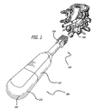
Fig. 1 is a rear perspective view of a lumbar segment of a spine with the dural sac retracted to the left showing a prepared recipient implantation site with a guard for providing guided access to the disc space and an embodiment of an inserter instrument and an embodiment of an implant in accordance with the present invention attached thereto approaching the disc space between the adjacent vertebral bodies. -
Fig. 2 is a fragmented side elevation view of the inserter instrument and implant ofFig. 1 . -
Fig. 3 is a cross sectional view of the implant ofFig. 1 taken along line 3-3 ofFig. 2 . -
Fig. 4 is an exploded perspective view of the trailing end of the implant ofFig. 1 and the rotatable member having deployable bone engaging projections. -
Fig. 5 is a partial perspective view of the leading end of the implant and the inserter instrument ofFig. 1 shown with bone engaging projections in a deployed position. -
Fig. 6 is an exploded perspective view of the leading end of implant ofFig. 1 . -
Fig. 7 is a cross sectional end view of another embodiment of an implant with the bone engaging projections in a retracted position in accordance with the present invention. -
Fig. 8 is a cross sectional side view of the implant ofFig. 7 taken along line 8-8 ofFig. 7 . -
Fig. 9 is a cross sectional end view of the implant ofFig. 7 with the bone engaging projections in a deployed position. -
Fig. 10 is a cross sectional top view of another embodiment of an implant. -
Fig. 11 is a cross sectional trailing end view of the implant ofFig. 10 with the bone engaging projections in a retracted position. -
Fig. 12 is a cross sectional end view of the implant ofFig. 10 with bone engaging projections in a deployed position. -
Fig. 13 is a front perspective view of another embodiment of an implant in accordance with the present invention with the bone engaging projections in a retracted position. -
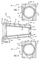
Fig. 14A is a cross sectional view along line 14-14 ofFig. 13 . -
Fig. 14B is a cross sectional view similar toFig. 14A of an alternative embodiment of an implant. -
Fig. 15 is a cross sectional view along line 14-4 ofFig. 13 with the bone engaging projections in a deployed position. -
Fig. 16 is a front perspective view of another embodiment of an implant with the bone engaging projections in a retracted position. -
Fig. 17 is a cross sectional view along line 17-17 ofFig. 16 . -
Fig. 18 is a cross sectional view along line 17-17 ofFig. 16 with the bone engaging projections in a deployed position. -
Fig. 19 is a fragmented cross sectional view along line 19-19 ofFig. 18 . -
Fig. 20 is an enlarged fragmentary view of a rotatable member and a bone engaging projection of another preferred embodiment of an implant in accordance with the present invention. -
Fig. 21 is an enlarged fragmentary view of a rotatable member and a bone engaging projection of yet another preferred embodiment of an implant in accordance with the present invention. -
Fig. 22 is a front perspective view of another preferred embodiment of an implant with the bone engaging projections in a retracted position. -
Fig. 23 is an exploded side elevation view of the implant ofFig. 22 . -
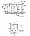
Fig. 24 is a top plan view in partial cross section of another preferred embodiment of an implant with the bone engaging projections in a retracted position. -
Fig. 25 a partial cross sectional end view along line 24--24 ofFig. 25 with the bone engaging projections in a retracted position shown in solid line and in a deployed position shown in hidden line. - Reference will now be made in detail to the present preferred embodiments (exemplary embodiments) of the invention, examples of which are illustrated in the accompanying drawings. Wherever possible, the same reference numbers will be used throughout the drawings to refer to the same or like parts.
-
Figs. 1-6 show a preferred embodiment of aspinal implant 100 and a preferred embodiment of animplant inserter 200 in accordance with the present invention.Implant 100 has anexternal housing 101 with aleading end 102 for insertion first into the disc space between two adjacent vertebral bodies of the human spine, a trailingend 104 oppositeleading end 102, anupper surface 106, alower surface 108, andsides 110, 112 between upper andlower surfaces end 102 may be tapered to facilitate insertion ofimplant 100 into the disc space.Housing 101 ofimplant 100 preferably has at least a portion along its longitudinal axis L that has a generally square cross section transverse to the longitudinal axis L. It is appreciated thathousing 101 can have a generally rectangular cross section or other cross-sectional configuration suitable for its intended purpose.Housing 101 preferably has ahollow interior 114 configured to hold bone growth promoting material. In this embodiment, upper andlower surfaces lower surfaces housing 101 preferably each have at least oneopening 116 in communication withhollow interior 114 and adapted to permit the growth of bone from adjacent vertebral body to adjacent vertebral body throughhousing 101. Upper andlower surfaces openings 118 configured to permit the passage therethrough ofbone engaging projections 132 described below fromhollow interior 114 to the exterior ofhousing 101.Sides 110, 112 ofimplant 100 can also haveopenings 116. -
Implant 100 has an internalrotatable member 120 configured to be preferably at least in part withinhollow interior 114 ofhousing 101 and as shown in this embodiment is insertable withinhollow interior 114 by the user. While in this embodiment,rotatable member 120 is shown entirely withinhollow interior 114 ofhousing 101, it is appreciated that the rotatable member need not be entirely withinhollow interior 114. For example, the rotatable member may have an external flange that is at least in part outside ofhollow interior 114.Rotatable member 120 is preferably substantially hollow and has aleading end 122, a trailingend 124, an exterior surface 126, and anopen interior 128. Trailingend 124 preferably is configured to cooperatively engage an instrument for rotatingrotatable member 120 such as, for example, inserter 200 (described below). For example, the inner perimeter of trailingend 124 can be hex-shaped or have any other configuration suitable for cooperatively engaging an instrument for rotatingrotatable member 120. Exterior surface 126 ofrotatable member 120 preferably has at least oneopening 130 that permits bone to grow therethrough. Preferably, at least one ofopenings 130 inrotatable member 120 is configured to generally align with at least one ofopenings 116 inhousing 101 to allow bone to grow from adjacent vertebral body to adjacent vertebral body thoughhousing 101 and throughrotatable member 120. - The upper and lower surfaces of
rotatable member 120 have at least onebone engaging projection 132 adapted to penetrably engage the bone of the adjacent vertebral bodies.Bone engaging projections 132 are preferably configured such that whenrotatable member 120 is in a retracted position,implant 100 may be linearly inserted into the disc space. Afterimplant 100 is inserted into the disc space,rotatable member 120 is moved to a deployed position so thatbone engaging projections 132 penetrably engage the endplates of an adjacent vertebral body and prevent expulsion ofimplant 100 from the disc space. - In an embodiment,
bone engaging projections 132 have a blade-like configuration oriented transverse to the longitudinal axis ofrotatable member 120 with a leading edge and a trailing edge angled relative to each other to form an apex adapted to penetrate the bone of a vertebral body. The blade-likebone engaging projections 132 are preferably of appropriate thickness, shape and sharpness to penetrate the vertebral bodies adjacent the disc space to be fused deep to the adjacent superficial endplate surfaces when the implant is in the deployed position.Bone engaging projections 132 are preferably oriented on opposite sides ofrotational member 120 and may, but need not, be diametrically opposite one another.Bone engaging projections 132 may be arranged such that at least the apexes of two oppositebone engaging projections 132 are on opposite sides of a mid-line passing therethrough. Such an over-center arrangement ofbone engaging projections 132 creates a more stable configuration of the implant when the bone engaging projections are fully deployed. Greater energy is required to de-rotate a rotatable member with opposed bone engaging projections when in an over-center arrangement as the apex of each bone engaging projection has to be moved through the mid-line to move from a deployed to a retracted position. - As will be appreciated by those skilled in the art, bone engaging projections other than blades may be employed that are suitable for the intended purpose. The number and orientation of the bone engaging projections along
rotatable member 120 may be varied without departing from the broad scope of the present invention. For example, at least two of the bone engaging projections may be arranged at an angle to the outer surface ofrotatable member 120, the angle may be 90 degrees or an angle other than 90 degrees to enhance the resistance ofimplant 100 to expulsion from the disc space. As another example,bone engaging projections 132 may also be oriented parallel to one another along at least a portion of the longitudinal axis ofimplant 100. - As shown in
Fig. 3 ,interior surface 134 ofhollow interior 114 ofhousing 101 preferably forms a pair of opposed abutment surfaces 136. Abutment surfaces 136 are configured to support and permitrotatable member 120 to rotate withinhollow interior 114 from a retracted to a deployed position to deploybone engaging projections 132. The rotation ofrotatable member 120 is limited whenbone engaging projections 132 contact abutment surfaces 136. The rotation ofrotatable member 120 can be limited to approximately 180 degrees or less about its axis of rotation so that it takes a half turn or less of the rotatable member to deploy the bone engaging projections. By way of example only and not limitation, the rotation ofrotatable member 120 can be limited to a range of approximately 25 degrees to approximately 65 degrees to move bone engaging projections from a retracted to a deployed position. Abutment surfaces 136 also may be configured to limit the rotation ofrotatable member 120 to approximately 90 degrees or less about its axis of rotation so that it takes a quarter turn or less of the rotatable member to deploy the bone engaging projections.Interior surface 134 ofhollow interior 114 preferably hasspaces 135 within thehollow interior 114 ofhousing 101 configured to receivebone engaging projections 132 in the retracted position such that the apex of each bone engaging projection is substantially in a corner ofhollow interior 114. In this position, the bone engaging projections are retained substantially within the hollow interior ofhousing 101. - Abutment surfaces 136 also preferably form a
shoulder 138 withinhollow interior 114 proximate trailingend 104 ofhousing 101 that is configured to permit and support the insertion ofrotatable member 120 intohollow interior 114 and retainrotatable member 120 therein in the deployed position.Shoulder 138 also is preferably configured to contact implant anengagement surface 212 ofinserter 200 as will be described below. The interior surface ofhollow interior 114 also preferably has a pair ofopposed grooves 140 proximate trailingend 104 that are adapted to engagetabs 214 ofinserter 200. It is appreciated that trailingend 104 may have any configuration known to those skilled in the art suitable for cooperatively engaging an appropriate insertion instrument. - As shown in
Figs. 5 and 6 ,rotatable member 120 is insertable intohollow interior 114 ofhousing 101. Afterrotatable member 120 is inserted intohollow interior 114 andimplant 100 is inserted into the disc space,rotatable member 120 is rotated such thatbone engaging projections 132 extend throughopenings 118 to project above upper andlower surfaces housing 101. It is appreciated that upper andlower surfaces openings 118 can be in the form of slots wherein the slots are configured to be in close tolerance withbone engaging projections 132 so as to supportbone engaging projections 132 when deployed. - As shown in
Fig. 4 ,hollow interior 114 ofhousing 101 andopen interior 128 ofrotatable member 120 are configured to hold bone growth materials therein. Examples of such bone growth materials include, but are not limited to, any of, or any combination of, bone in any of its forms, materials derived from bone, bone morphogenetic proteins, mineralizing proteins, genetic materials coding for the production of bone or any substance capable of inducing the formation of bone or useful for achieving fusion for the intended purpose. The rotation ofrotatable member 120, when rotated between a retracted and a deployed position, does not substantially displace bone growth material from withinhollow interior 114 ofhousing 101 and/oropen interior 128 ofrotatable member 120. Accordingly,implant 100 androtatable member 120 can be loaded with bone growth material prior to insertion of the implant into the disc space and prior to deployment of the bone engagement projections. Alternatively,housing 101 androtatable member 120 can be loaded with bone growth material after insertion of the implant at least in part within the disc space either before or after rotation ofrotatable member 120 and may be further loaded after deployment of the bone engaging projections as desired. -
Figs. 1 ,2 and5 show apreferred implant inserter 200 for use with the implant of the present invention.Inserter 200 preferably has anouter shaft 202 with adistal end 204, aproximal end 206, and a reduced diametermedial portion 208.Distal end 204 preferably has ahead portion 210 with animplant engagement surface 212 located distally thereto.Head portion 210 preferably has a cross section transverse to the longitudinal axis ofinserter 200 corresponding to the transverse cross sectional configuration of at least the outer perimeter of trailingend 104 ofimplant 100. -
Implant engagement surface 212 is preferably sized and shaped to cooperatively contactshoulder 138 ofhollow interior 114 ofhousing 101.Implant engagement surface 212 also preferably has opposedtabs 214 that are adapted to snap intogrooves 140 ofhousing 101. -
Head portion 210 also preferably has a pair oflongitudinal recesses 216 extending between anupper surface 218 and alower surface 220 ofhead portion 210.Recesses 216permit head portion 210 to be resiliently compressed so thattabs 214 may be inserted intogrooves 140 of housing and then locked into place when released.Outer shaft 202 also preferably has ahandle 222 at itsproximal end 206. -
Inserter 200 also has aninner shaft 224 that is rotatable withinouter shaft 202.Inner shaft 224 has adistal end 226 and aproximal end 228.Distal end 226 ofinner shaft 224 hasrotational engagement surface 230 that is preferably configured to cooperatively engage trailingend 124 ofrotatable member 120. In a preferred embodiment,rotational engagement surface 230 is hex-shaped.Proximal end 228 ofinserter 200 preferably has ahandle 232 with an outer perimeter corresponding to the outer perimeter ofhandle 222 ofouter shaft 202. Handle 232 is preferably proximal ofhandle 222 so that the surgeon may rotateinner shaft 224 viahandle 232 while holdinghandle 222. In a preferred embodiment,inserter 200 preferably stabilizeshousing 101 ofimplant 100 while rotatingrotatable member 120 to deploybone engaging projections 132.Inserter 200 is preferably a combination holder, driver, extractor, housing stabilizer, and rotator all in one. - While a preferred embodiment of an
inserter 200 is shown, it is appreciated that any other inserter suitable for the intended purpose known to those skilled in the art may be used to insert the implants of the present invention. - In
Figs. 7-9 , another preferred embodiment of the implant of the present invention is shown and generally referred to by thereference number 300.Implant 300 is similar to implant 100 but has a height that is greater than its width.Implant 300 preferably has ahousing 301 with upper andlower surfaces lower surfaces implant 300. Similarly, sides 310, 312 can be angled relative to one another. It is appreciated that implant upper andlower surfaces -
Implant 300 has arotatable member 320 that is preferably frustoconical in shape.Rotatable member 320 hasbone engaging projections 332 adapted to penetrably engage the bone of the adjacent vertebral bodies.Bone engaging projections 332 are preferably configured such that in a retracted position,implant 300 may be linearly inserted into the disc space. Afterimplant 300 is inserted into the disc space,bone engaging projections 332 are moved to a deployed position to penetrably engage the endplates of each adjacent vertebral body and prevent the expulsion ofimplant 300 from the disc space. The rotation ofrotatable member 320 can be limited to approximately 180 degrees or less about its axis of rotation so that it takes a half turn or less of the rotatable member to deploy the bone engaging projections. By way of example only and not limitation, the rotation ofrotatable member 320 can be limited to a range of approximately 25 degrees to approximately 65 degrees to move bone engaging projections from a retracted to a deployed position. - To support and facilitate the rotation of
rotatable member 320, hollow 314 ofhousing 301 preferably has asecond shoulder 342 proximate to afirst shoulder 338.First shoulder 338 is preferably configured for engagement with the distal end of a suitably configuredinserter 200.Second shoulder 342 supports a trailingend 324 ofrotatable member 320. Aleading end 322 ofrotatable member 320 preferably has acylindrical extension 344 for insertion into anopening 346 at leadingend 302 ofhousing 301.Cylindrical extension 344 serves as an axle to support leadingend 322 and permit rotation ofrotatable member 320 within hollow 314 ofimplant 300.Rotatable member 320 may have openings in its surface along its longitudinal axis to permit bone to grow throughrotatable member 320 and have an open interior. - In
Figs. 10-12 , another for insertion into the spine from an anterior approach is shown and generally referred to by thereference number 400.Implant 400 is similar to implant 300 except that it has a width greater than its height and has tworotatable members 420 withinhollow interior 414 ofhousing 401.Housing 101 preferably has upper and lower surfaces 406, 408 that are angled with respect to one another and an overall width that is generally greater than one half the width of the disc space into which implant 400 is to be inserted. - Trailing
end 404 ofhousing 401 may have an anatomical configuration to utilize the apophyseal rim bone around the perimeter of each vertebral body to help support the implant, and/or avoid the need to deeply countersink the implant so as to avoid a lateral corner of the implant from protruding beyond the perimeter of the vertebral bodies. Examples of such configurations are inU.S. Patent 6,241,770 to Michelson , entitled "Implant with Anatomically Conformed Trailing End," the disclosure of which is hereby incorporated by reference.Housing 401 hasinternal openings 446 proximateleading end 402 configured to supportrotatable members 420 and are preferably configured to have awider diameter portion 452 and a reduceddiameter portion 454.Wider diameter portion 452 is configured to receive andsupport leading end 422 of arotatable member 420 while reduceddiameter portion 454 acts as a stop to preventrotatable member 420 from moving toward leadingend 402 ofhousing 401. - Rotatable
members 420 are positioned to either side of the mid-longitudinal axis ofhousing 401. The rotatable members may be adapted to rotate in the same or opposite directions. - In
Figs. 13, 14A and 15 , another preferred embodiment of the implant of the present invention is shown and generally referred to by thereference number 500.Implant 500 has anexternal housing 501 with aleading end 502 for insertion first into the disc space between two adjacent vertebral bodies of the human spine, a trailingend 504 oppositeleading end 502, anupper surface 506, alower surface 508, andsides lower surfaces Housing 501 ofimplant 500 has ahollow interior 514 configured to hold bone growth promoting material. In this embodiment, upper andlower surfaces arcuate portion 507 and at least anon-arcuate portion 509 nearsides Non-arcuate portions 509 of upper andlower surfaces implant 500 in inserted into the disc space.Arcuate portions 507 of upper andlower surfaces - Upper and
lower surfaces implant 500 preferably each have at least oneopening 516 in communication withhollow interior 514 ofhousing 501 and adapted to permit the growth of bone from adjacent vertebral body to adjacent vertebral body throughimplant 500. Upper andlower surfaces openings 518 configured to permit the passage therethrough ofbone engaging projections 532 described below fromhollow interior 514 to the exterior ofhousing 501.Sides implant 500 can also haveopenings 516. -
Implant 500 has an internalrotatable member 520 configured to be inserted intohollow interior 514 ofhousing 501 preferably through an opening at trailingend 504 ofimplant housing 501. Alternatively,housing 501 ofimplant 500 need not be one piece, such as forexample housing 501 may be split into upper and lower portions. With the upper and lower portions apart,rotatable member 520 can be placed intohollow interior 514 and thenhousing 501 can be reassembled by putting together upper and lower portions andimplant 500 can then be inserted into the disc space. In this manner,bone engaging projections 532 may be at least in part within the thickness of the wall ofhousing 501 when inopenings 518 and not extend beyond the exterior ofimplant 500 in the retracted position. -
Rotatable member 520 is preferably substantially hollow and has a leading end 522, a trailing end 524, an exterior surface 526, and an open interior 528. Trailing end 524 preferably is configured to cooperatively engage an instrument for rotatingrotatable member 520 such as, for example, an inserter similar toinserter 200 described above. Exterior surface 526 ofrotatable member 520 preferably has at least one opening 530 that permits bone to grow therethrough. Preferably, at least one of openings 530 inrotatable member 520 is configured to generally align with at least one ofopenings 516 inhousing 501 to allow bone to grow from adjacent vertebral body to adjacent vertebral body throughhousing 501 and throughrotatable member 520. - The upper and lower surfaces of
rotatable member 520 have at least onebone engaging projection 532 adapted to penetrably engage the bone of the adjacent vertebral bodies similar tobone engaging projections 132 described above.Bone engaging projections 532 are preferably configured such that whenrotatable member 520 is in a retracted position,implant 500 may be linearly inserted into the disc space. Afterimplant 500 is inserted into the disc space,rotatable member 520 is moved to a deployed position so thatbone engaging projections 532 penetrably engage into the adjacent vertebral bodies. The rotation ofrotatable member 520 can be limited to approximately 180 degrees or less about its axis of rotation so that it takes a half turn or less of the rotatable member to deploy the bone engaging projections. By way of example only and not limitation, the rotation ofrotatable member 520 can be limited to a range of approximately 45 degrees to approximately 100 degrees to move bone engaging projections from a retracted to a deployed position. -
Bone engaging projections 532 are preferably oriented on opposite sides ofrotational member 520 and may, but need not, be diametrically opposite one another.Bone engaging projections 532 may be arranged such that at least the apexes of two oppositebone engaging projections 532 are on opposite sides of a mid-line passing therethrough. Such an over-center arrangement ofbone engaging projections 532 creates a more stable configuration of the implant when the bone engaging projections are fully deployed. Greater energy is required to de-rotate a rotatable member with opposed bone engaging projections when in an over-center arrangement as the apex of each bone engaging projection has to be moved through the mid-line to move from a deployed to a retracted position. - As shown in
Fig. 14A , interior surface 534 ofhollow interior 514 ofhousing 501 preferably forms a pair of opposed abutment surfaces 536. Abutment surfaces 536 are configured to support and permitrotatable member 520 to rotate withinhollow interior 514 from a retracted to a deployed position to deploybone engaging projections 532. The rotation ofrotatable member 520 is limited whenbone engaging projections 532 contact abutment surfaces 536. The rotation ofrotatable member 520 can be limited to approximately 180 degrees or less about its axis of rotation so that it takes a half turn or less of the rotatable member to deploy the bone engaging projections. Abutment surfaces 536 also may be configured to limit the rotation ofrotatable member 520 to approximately 90 degrees or less about its axis of rotation so that it takes a quarter turn or less of the rotatable member to deploy the bone engaging projections. Interior surface 534 ofhollow interior 514 preferably has spaces configured to receivebone engaging projections 532 in the retracted position such that the apex of each bone engaging projection is substantially in a corner ofhollow interior 514. In this position, the bone engaging projections are retained substantially within the hollow interior ofhousing 501. - In
Fig. 14B , another is shown and generally referred to by the reference number 500'. Implant 500' is similar toimplant 500, except that upper and lower surfaces 506', 508' each preferably having at least two arcuate portions 507' and at least some non-arcuate portion 509' either between or lateral to arcuate portions 507' and/ornear sides 510', 512'. Non-arcuate portions 509' of upper and lower surfaces 506', 508' are adapted to be oriented toward the vertebral bodies and, if still present, the endplates adjacent the disc space and are configured to support the adjacent vertebral bodies when implant 500' is inserted into the disc space. Arcuate portions 507' of upper and lower surfaces 506', 508' are preferably located on opposite sides of the mid-longitudinal axis of implant 500'. Such a configuration helps to further reduce or eliminate any potential rocking motion that might otherwise occur with an implant having a centrally placed single arcuate portion. Arcuate portions 507' may be generally parallel to each other or at an angle to each other. Having two or more arcuate portions 507' provides for more surface area of implant 500' to contact the bone of the adjacent vertebral bodies and may also provide for access to the vascular bone of the adjacent vertebral bodies. Implant 500' having at least two arcuate portions 507' has a height that is less than an implant with a single arcuate portion having the same combined width of two arcuate portions 507'. Furthermore, implant 500' having at least two arcuate portions 507' provides the added advantage of utilizing the stronger more dense bone of the adjacent vertebral bodies located closer to the disc space. - Implant 500' preferably has at least two internal rotatable members 520' configured to be inserted into hollow interior 514' of housing 501' preferably through an opening at one of the trailing and leading ends of implant housing 501' or the implant may be opened, such as by way of example only by having the upper and lower portions of the housing configured to be separable, to permit the placement of rotatable members 520' into hollow interior 514'. Then, housing 501' can be reassembled by putting together upper and lower portions and implant 500' can then be inserted into the disc space.
- In
Figs. 16-19 , another implant is shown and generally referred to by thereference number 600.Implant 600 is similar to implant 500 except for the configuration ofbone engaging projections 632.Bone engaging projections 632 preferably have a base portion that extends fromrotatable member 620 and terminates in a larger dimension upper portion. The upper portion ofbone engaging projection 632 preferably has a transverse cross sectional dimension that is greater than the transverse cross sectional dimension of the base portion. By way of example only and not limitation, the base portion and the upper portion ofbone engaging projection 632 can have a T-shaped cross section as shown inFig. 19 . The transverse cross sectional configuration ofbone engaging projections 632 can have other configurations, including but not limited to, C-shaped, V-shaped, W-shaped, Y-shaped, and any other configuration suitable for the intended purpose.Bone engaging projections 632 preferably have aleading edge 633 that is at least in part curved and the upper portion ofbone engaging projection 632 is preferably tapered proximateleading edge 633 to facilitate penetration ofbone engaging projection 632 into the bone of the vertebral bodies. Similarly,openings 618 preferably have a configuration shaped to permitbone engaging projections 632 to extend from hollow interior 614 ofhousing 601 and throughopenings 618 when deployed. -
Implant 600 is inserted into the disc space andbone engaging projections 632 are deployed to penetrably engage the bone of the adjacent vertebral bodies. The configuration ofbone engaging projections 632 provide for increased stability of the implant relative to the adjacent vertebral bodies and of the vertebral bodies relative to each other. Further, the configuration ofbone engaging projections 632 limit the ability of the vertebral bodies to move apart from one another to further enhance stability. - As shown in
Fig. 20 , in a further variation, the upper portion of the T-shaped configuration of bone engaging projections 632' increases in thickness at least in part from leading edge 633' to trailing edge 635' so that it is closer to the housing ofimplant 600 in the deployed position and brings the vertebral bodies closer together so as to compressively load the vertebral bodies towards the implant when the bone engaging projections are fully deployed. In this configuration the upper portion of bone engaging projection 632' has a decreased distance from housing of the implant at its trailing edge than at its leading edge when the bone engaging projections are in the deployed position. - As shown in
Fig. 21 , in a further alternative configuration,bone engaging projections 632" have a lower portion opposite the upper portion of the T-shaped configuration. The lower portion of the T-shaped configuration has an arc of radius that is less than the arc of radius of the upper portion of the T-shaped configuration resulting in a decreased distance from the housing of the implantproximate trailing edge 635" than proximateleading edge 633" whenbone engaging projections 632" are in the deployed position. Such a configuration ofbone engaging projections 632" provides for the compressive loading of the vertebral bodies towards the implant when the bone engaging projections are fully deployed. - In
Figs. 22 and 23 , another implant is shown and generally referred to by thereference number 700.Implant 700 is similar to implant 600 except for the configuration ofhousing 701. Each of upper andlower surfaces housing 701 preferably has an open area in communication withhollow interior 714 ofhousing 701. The open area preferably forms a window 703 (a large opening) in each of upper andlower surfaces rotatable member 720.Rotatable member 720 is exposed to the adjacent vertebral bodies throughwindows 703.Rotatable member 720 may project at least in part through thewindows 703 to contact the adjacent vertebral bodies. In a preferred embodiment,rotatable member 720 may protrude at least in part throughwindows 703 to be flush with the exterior ofhousing 701.Housing 701 is preferably configured to be opened to receiverotatable member 720 therein and closed to holdrotatable member 720 at least in part withinhousing 701. By way of example only and not limitation,housing 701 may be separable into upper and lower portions atseam 705. - In
Figs. 24 and 25 , another implant is shown and generally referred to by thereference number 800.Implant 800 is similar to implant 100 except that it preferably has at least two internalrotatable members 820 for deployingbone engaging projections 832 through upper and lower surfaces 806, 808 of housing 801. Rotatablemembers 820 are preferably at least in part within hollow interior 814 of housing 801 proximate upper and lower surfaces 806, 808, respectively. Rotatablemembers 820 are preferably held in rotational relationship to housing 801 bysupport structures 809. Each ofrotatable members 820 preferably have at least oneend 824 configured to cooperatively engage an instrument for rotatingrotational members 820 to deploybone engaging projections 832. The rotation ofrotatable member 820 can be in the preferred range of approximately 200 degrees to approximately 25 degrees about its axis of rotation so that it takes less than a full turn of the rotatable member to deploy the bone engaging projections. By way of example only and not limitation,rotational member 820 can be rotated more than 180 degrees, for example approximately 195 degrees, to deploybone engaging projections 832 in an over center position. Whilerotational members 820 can be solid or at least in part hollow, in this instance a generally solid configuration is preferred so that each ofrotational members 820 preferably has a relatively small cross sectional dimension transverse to its longitudinal axis such thatrotational members 820 occupy only a small portion of the interior of housing 801. - Housing 801 of
implant 800 preferably has at least a portion along its longitudinal axis that has a generally square cross section transverse to the longitudinal axis. It is appreciated that housing 801 can have a generally rectangular cross section or other cross-sectional configuration suitable for its intended purpose. The implant may be inserted into the disc space on its side and then flipped 90 degrees to orient the upper and lower surfaces of the implant toward the adjacent vertebral bodies, respectively. Such an implant would preferably have a reduced dimension between a pair of diagonally opposed corners. For example, such an implant could have diagonal corners that are rounded to facilitate the 90 degree rotation of the implant between the adjacent vertebral bodies as taught by Michelson inU.S. Application No. 09/429,628 for a "Self-Broaching, Rotatable, Push-In Interbody Spinal Fusion Implant and Method for Deployment Thereof", the portions of the specification directed to the reduced dimension between a pair diagonally opposed corners. Upper and lower surfaces 806, 808 ofimplant 800 are preferably at least in part non-arcuate and are generally parallel to each other along at least a portion of the longitudinal axis ofimplant 800. Alternatively, upper and lower surfaces 806, 808 can be angled relative to one another along at least a portion of the longitudinal axis ofimplant 800. -
Figs. 1-5 show various steps of a preferred method for insertingimplant 100 from a posterior approach to the spine and using associated instrumentation disclosed herein. - By way of example and not limitation, preferred steps of methods for installing the implants of the present invention include but are not limited to the steps summarized below.
- 1. Identifying the disc space to be operated upon;
- 2. Providing access to the disc space;
- 3. Utilizing a guard or retractor to provide protected access to the disc space;
- 4. Removing sufficient disc material to allow an implant to be inserted at least in part within and across the height of the disc space;
- 5. Distracting the disc space between the vertebral bodies to generally restore the height of the disc space with or without the use of a distractor;
- 6. Utilizing a guard with disc penetrating extensions to provide protected access to the disc and to distract the vertebral bodies adjacent the disc space;
- 7. Working upon the endplates of the adjacent vertebral bodies, which may include for example scraping the endplates, decorticating the endplates, or cutting away at least a portion of the endplates;
- 8. Attaching the implant to an implant inserter;
- 9. Inserting the implant at least in part into the disc space;
- 10. Loading the implant with bone growth promoting material: (i) prior to implantation of the implant, (ii) after implantation of the implant, or (iii) both prior to implantation and after implantation of the implant;
- 11. Packing bone growth promoting material around the implant and pushing bone through the implant and into the area around the implant;
- 12. Rotating the hollow internal member to deploy the bone engaging projections to penetrably engage the vertebral bodies adjacent the disc space, which may include rotating the internal member less than 180 degrees;
- 13. Removing the inserter from the implant; and/or
- 14. Repeating the procedure at same disc level if necessary.
- The methods for installing the implants of the present invention are not limited to the steps identified above, need not include all the steps recited above, and need not be performed in the order listed above. By way of example only and not limitation, two implants may be inserted into the disc space before either has its internal rotatable member rotated to deploy the bone engaging projections, or the implant may be inserted into the disc space prior to being packed with bone growth promoting material or prior to the bone growth promoting material being forced through the openings in the implant. Other methods for installing implants known to those skilled in the art may be used to install the implants of the present invention may be used without departing from the scope of the present invention.
- Preferred instruments and methods of preparing the disc space are disclosed and taught by Michelson in
U.S. Patent No. 6,159,214 entitled "Milling Instrumentation and Method for Preparing a Space Between Adjacent Vertebral Bodies";U.S. Patent Application No. 60/255,463 entitled "Spinal Interspace Shaper";U.S. Patent No. 6,083,228 entitled "Device and Method for Preparing a Space Between Adjacent Vertebrae to Receive an Insert";U.S. Patent No. 6,224,607 entitled "Instrument and Method for Creating an Intervertebral Space for Receiving an Implant"; and WIPO publicationWO 99/63891 - It is appreciated that other instruments and methods may be used to prepare the disc space to receive the implant of the present invention.
- Where it is desirable, the surgeon may utilize a guard such as
guard 500 shown inFig. 1 for protecting adjacent delicate neurological structures.Guard 500 may be left in place after the preparation of the disc space such that the described operation can be performed throughguard 500 and be removed at its completion. The implantation space may have any configuration suitable to receive the implant to be inserted therein. - Prior to preparing the disc space, if it is desirable, the surgeon may distract the vertebral bodies with a distractor having disc penetrating extensions such as that taught by Michelson in
U.S. Patent No. 5,484,437 entitled "Apparatus and Method of Inserting Spinal Implants" andU.S. Patent No. 5,797,909 (the '909 patent), entitled "Apparatus for Inserting Spinal Implants" . - If necessary, the surgeon may impart an angulation to the adjacent vertebral bodies with a distractor having disc penetrating extensions with angled upper and lower surfaces such as that taught in the '909 patent to Michelson.
- As shown in
Figs. 2 and5 ,rotatable member 120 may be inserted intohollow interior 114 ofimplant 100 anddistal end 204 ofinserter 200 is cooperatively engaged to trailingend 104 ofimplant 100 such thattabs 214 ofimplant engagement surface 212 are engaged withgrooves 140 ofimplant 100. It is appreciated thatrotatable member 120 may be inserted intohollow interior 114 ofhousing 101 afterimplant 100 is inserted into the disc space.Implant 100 is inserted into the disc space preferably by linear insertion without substantial rotation ofimplant 100 to the appropriate depth as desired by the surgeon. Alternatively, the implant be can be rotated at least in part during its implantation into the disc space, but is not screwed into the disc space. For example, the implant may be inserted into the disc space on its side and then rotated 90 degrees to place the upper and lower surfaces ofhousing 101 in contact with the adjacent vertebral bodies, respectively.Bone engaging projections 132 can then be deployed. Trailingend 104 ofimplant 100 preferably does not protrude beyond the posterior aspects of the adjacent vertebral bodies, and preferably no substantial portion ofimplant 100 protrudes from the outer perimeter of the adjacent vertebral bodies. During insertion ofimplant 100,bone engaging projections 132 are retained in the retracted position to facilitate linear insertion ofimplant 100 into the disc space. - After
implant 100 is properly positioned in the implantation space, thebone engaging projections 132 can be deployed. In a preferred embodiment,inner shaft 224 ofinserter 200 is rotated by the surgeon to rotaterotatable member 120 ofimplant 100 from a retracted position to a deployed position so thatbone engaging projections 132 extend through upper andlower surfaces implant 100 to penetrably engage the end plates of the adjacent vertebral bodies and prevent the expulsion of the implant from the disc space. In a preferred embodiment,rotatable member 120 is rotated one half turn or less to deploy the bone engaging projections. -
Implant inserter 200 is detached fromimplant 100 and removed. A cap may be installed to close at least part of the implant's trailing end to prevent bone from growing into the spinal canal, or to limit adhesions of the neurological structures at the canal floor, or to otherwise protect the neurological structures. One of the purposes for a cap includes restricting the passage of fusion-promoting materials so that they remain loaded within the implant. - Preferably prior to insertion,
hollow interior 114 ofimplant 100 andopen interior 128 ofrotatable member 120 may be loaded with fusion promoting materials including any of, or any combination of, bone in any of its forms, materials derived from bone, bone morphogenetic proteins, mineralizing proteins, genetic materials coding for the production of bone or any substance capable of inducing the formation of bone or useful for achieving fusion for the intended purpose. The fusion promoting materials may be loaded or preferably compressively loaded intohollow interior 114 ofimplant 100 and/oropen interior 128 ofrotatable member 120 by use of an instrument such as, for example, a tamp, press, or piston at any time during the procedure as desired by the surgeon. Additionally, scar tissue-inhibiting and/or antimicrobial materials may be applied to the implant. - When said methods and instrumentation are used to install such implants posteriorly, the technique may further include the application of scar tissue inhibiting substances posterior to the implant trailing end and at the floor of the spinal canal.
- When performing the procedure from a posterior approach to the spine, it is generally preferred that the procedure be performed on both sides of the saggital midline of the disc space and that two
implants 100, each having a width less than half the width of the disc space be inserted from a posterior to anterior approach either generally parallel or alternatively from a generally posterior to anterior approach in a "toed-in" configuration. Having completed the procedure on a first side, the procedure is then repeated as already described on the opposite side of the saggital midline of the same disc space leading to the implantation of twoimplants 100 in the same disc space. - If
implants 300 are being inserted into the disc space, then the procedure may preferably include distracting the adjacent vertebral bodies to impart an angulation to the adjacent vertebral bodies with a distractor such as that taught in the '909 patent to Michelson to accommodate the insertion of each ofimplants 300. In another alternative method, both implants may be implanted from an anterior approach to the spine using many of the same steps already described. - When performing the method from the anterior approach, a plurality of
implants 100 or 300 (for example two or three) or a single implant such asimplant 400 may be used as the spinal cord is not in the path of insertion of the implant. When using a laparoscope or when it is difficult to mobilize the great vessels two or more smaller implants may be used in order to use a smaller working space. - The various features of the preferred embodiments of the present inventions described herein are combinable with one another and are not limited to a particular embodiment of the implant for which the features are described. By way of example only and not limitation, it is appreciated that for any of the embodiments of the implants of the present invention, the external housing may be formed of two or more pieces that can be separated to permit insertion of the internal rotatable member within the housing and then reassembled for installation into the disc space; and the various embodiments of the bone engaging projections described herein may be utilized with any of the embodiments of the implants of the present invention.
- The spinal fusion implant of the present invention may comprise of any artificial or naturally occurring implant material suitable for implantation in a human being. The implant of the present invention can be formed of a material such as metal including, but not limited to, titanium and its alloys, surgical grade plastics, composites, ceramics, or other materials suitable for use as a spinal fusion implant. The implant of the present invention can comprise at least in part of a material that is resorbable by the human body. The implant of the present invention can be formed at least in part of a porous material or can be formed at least in part of a material that intrinsically participates in the growth of bone from one of adjacent vertebral bodies to the other of adjacent vertebral bodies.
- Further, the implant of the present invention may be comprised of, treated with, coated, or filled with a fusion promoting substance. The implant may be used in combination with a fusion promoting substance including, but not limited to, bone, bone derived products, demineralized bone matrix, ossifying proteins, bone morphogenetic proteins, hydroxyapatite, and genes coding for the production of bone.
- Where such implants are for posterior implantation, the trailing ends of such implants may be treated with, coated with, or used in combination with substances to inhibit scar tissue formation in the spinal canal. The implants of the present invention may be adapted to facilitate the electrostimulation of the implant or a portion thereof and/or of the fusion area into which they are inserted and the proximate bone thereabout. The implant of the present invention may be comprised at least in part of, coated with, or used in combination with materials to make it antimicrobial, such as, but not limited to, antibiotics, silver ions or any other substance suitable for the intended purpose.
- There is disclosed in the above description and the drawings implants and instruments and methods for use therewith, which fully and effectively accomplish the objectives of this invention. However, it will be apparent that variations and modifications of the disclosed embodiments may be made without departing from the principles of the invention.
Claims (24)
- An interbody spinal fusion implant (100, 300) for implantation at least in part within and across the generally restored height of a disc space between two adjacent vertebral bodies of a human spine, said spinal implant (100, 300) comprising:a housing (101, 301) having a leading end (102, 302) for insertion first into the disc space, a trailing end (104, 304) opposite said leading end, a mid-longitudinal axis between said leading end (102, 302) and said trailing end (104, 304) of said housing (101, 301), an upper surface (106, 306) adapted to contact one of the adjacent vertebral bodies, a lower surface (108, 308) opposite said upper surface (106, 306) adapted to contact another one of the adjacent vertebral bodies, a height between said upper (106, 306) and lower (108, 308) surfaces, and a hollow interior (114, 314) configured to hold bone growth promoting material therein, said upper (106, 306) and lower (108, 308) surfaces each having at least one opening (116, 316) therein in communication with said hollow interior (114, 314) and with each other to permit for the growth of bone from adjacent vertebral body to adjacent vertebral body through said housing (101, 301), said hollow interior (114, 314) having a maximum width perpendicular to the height and the mid-longitudinal axis of said housing (101, 301); andan internal rotatable member (120, 320) configured to be at least in part within said hollow interior (114, 314) of said housing (101, 301), said rotatable member (120, 320) having a leading end (122, 322), a trailing end (124, 324), a mid-longitudinal axis between said leading end (122, 322) and said trailing end (124, 324) of said rotatable member (120, 320), a top, and a bottom, each of said top and said bottom of said rotatable member (120, 320) including at least one bone engaging projection (132, 332) adapted to penetrably engage the bone of the adjacent vertebral bodies by rotating said bone engaging projection (132, 332) about the mid-longitudinal axis of said rotatable member (120, 320), said rotatable member (120, 320) being adapted to rotate at least in part within said hollow interior (114, 314) of said housing (101, 301) between a retracted position and a deployed position, said bone engaging projections (132, 332) extending through said upper (106, 306) and lower surfaces (108, 308) of said housing (101, 301) so as to penetrably engage the bone of the adjacent vertebral bodies when in the deployed position, said rotatable member (120, 320) having a first dimension measured from one of said bone engaging projections (132, 332) on said top to the mid-longitudinal axis along a line perpendicular to the mid-longitudinal axis and a second dimension measured from one of said bone engaging projections (132, 332) on said bottom to the mid-longitudinal axis along a line perpendicular to the mid-longitudinal axis, the sum of said first and second dimensions being greater than the maximum height of said hollow interior (114, 314) of said housing (101, 301), characterised by said top and said bottom of the internal rotatable member including at least one aperture (130, 330) therein in communication with each other to permit for the growth of bone from vertebral body to vertebral body therethrough and the interior (114, 314) of said housing (101, 301) being configured to limit the degree of rotation of said rotatable member (120,320) within said housing.
- The implant (100, 300) of claim 1, wherein said rotatable member (120, 320) is substantially hollow and has an open interior (128, 328) between said top and said bottom.
- The implant (100, 300) of any one of the above claims, wherein said bone engaging projections (132, 332) have a leading edge, when in the deployed position said leading edge of at least two of said bone engaging projections on said top and said bottom of said rotatable member (120, 320), respectively, are oriented in an over-center position.
- The implant (100, 300) of any one of the above claims, wherein at least one of said bone engaging projections (132, 332) has a base portion extending from said rotatable member (120, 320) and terminating in an upper portion having a length and width, said upper portion having a width that is greater than the width of said base portion.
- The implant (100, 300) of any one of the above claims, wherein at least one of said bone engaging projections (132, 332) has a sharp leading edge adapted to cut into bone.
- The implant:(100, 300) of any one of the above claims, wherein said housing (101, 301) and said rotatable member (120, 320) cooperate so as to limit rotation of said rotatable member (120, 320) to no more than 180 degrees.
- The implant (100, 300) of any one of the above claims, wherein said housing (101, 301) and said rotatable member (120, 320) cooperate so as to limit rotation of said rotatable member (120, 320) to no more than 90 degrees.
- The implant (100, 300) of any one of the above claims, wherein said rotatable member (120, 320) is at least in part cylindrical.
- The implant (100, 300) of any one of claims 1 -7, wherein said rotatable member (120, 320) is at least in part frustoconical.
- The implant (100, 300) of claim 1, wherein at least a portion of said apertures (130, 330) of said rotatable member (120, 320) when in said deployed position are configured to generally align with at least a portion of said openings (116, 316) of said housing (101, 301) to allow bone to grow from adjacent vertebral body to adjacent vertebral body through said housing (101, 301) of said implant (100, 300) and through said rotatable member(120, 320).
- The implant (100, 300) of any one of the above claims, wherein said housing (101, 301) has a transverse cross section that is at least in part generally square along at least a portion of the mid-longitudinal axis of said housing(101 301).
- The implant (100, 300) of any one of the above claims, wherein said upper (106, 306) and lower (108, 308) surfaces of said housing (101, 301) are at least in part angled to each other.
- The implant (100, 300) of any one of claims 1 -10, further comprising at least one arcuate portion in said upper (106, 306) and lower (108, 308) surfaces of said housing (101, 301), respectively.
- The implant (100, 300) of any one of claims 1 -10, wherein at least one of said upper (106, 306) and said lower (108, 308) surfaces of said housing (101, 301) is at least in part non-arcuate from side to side.
- The implant (100, 300) of any one of the above claims, wherein at least one of said leading (102, 302) and said trailing (104, 304) ends of said housing (101, 301) is open to permit for loading of bone growth promoting material inside of said housing (101, 301), further comprising an end cap for closing said open end of said housing (101, 301).
- The implant (100, 300) of any one of the above claims, wherein at least one of said leading (102, 302) and said trailing (104, 304) ends of said housing (101, 301) is configured to permit said rotatable member (120, 320) to be inserted at least in part within said hollow interior (114, 314) of said housing (101, 301).
- The implant (100, 300) of any one of the above claims, wherein said hollow interior (114, 314) of said housing (101, 301) includes at least one abutment surface (135, 335) adapted to contact a portion of said rotatable member (120, 320) to limit the rotation of said rotatable member (120, 320).
- The implant (100, 300) of claim 1, wherein said implant (100, 300) has a height as measured from said upper surface (106, 306) to said lower surface (108, 308) and a width that is greater than the height of said implant (100, 300).
- The implant (100, 300) of claim 1, wherein said implant (100, 300) has a height as measured from said upper surface (106, 306) to said lower surface (108, 308) that is greater than the width of said implant (100, 300).
- The implant (100, 300) of any one of the above claims, in combination with a bone growth promoting material.
- The implant (100, 300) of claim 20, wherein said bone growth promoting material is selected from one of bone, bone derived products, demineralized bone matrix, ossifying proteins, bone morphogenetic protein, hydroxyapatite, and genes coding for the production of bone.
- The implant (100, 300) of any one of the above claims, wherein said implant (100, 300) is at least in part resorbable.
- The implant (100, 300) of any one of the above claims, in combination with a chemical substance adapted to inhibit scar formation.
- The implant (100, 300) of any one of the above claims, in combination with an antimicrobial material.
Applications Claiming Priority (3)
| Application Number | Priority Date | Filing Date | Title |
|---|---|---|---|
| US62805 | 1987-06-15 | ||
| US10/062,805 US6923830B2 (en) | 2002-02-02 | 2002-02-02 | Spinal fusion implant having deployable bone engaging projections |
| PCT/US2003/000042 WO2003065930A2 (en) | 2002-02-02 | 2003-01-23 | Spinal fusion implant having deployable bone engaging projections |
Publications (3)
| Publication Number | Publication Date |
|---|---|
| EP1469800A2 EP1469800A2 (en) | 2004-10-27 |
| EP1469800A4 EP1469800A4 (en) | 2007-01-03 |
| EP1469800B1 true EP1469800B1 (en) | 2009-04-15 |
Family
ID=27658608
Family Applications (1)
| Application Number | Title | Priority Date | Filing Date |
|---|---|---|---|
| EP03705644A Expired - Lifetime EP1469800B1 (en) | 2002-02-02 | 2003-01-23 | Spinal fusion implant having deployable bone engaging projections |
Country Status (9)
| Country | Link |
|---|---|
| US (8) | US6923830B2 (en) |
| EP (1) | EP1469800B1 (en) |
| JP (1) | JP4295625B2 (en) |
| AT (1) | ATE428382T1 (en) |
| AU (1) | AU2003207437B2 (en) |
| CA (1) | CA2474732C (en) |
| DE (1) | DE60327165D1 (en) |
| ES (1) | ES2322573T3 (en) |
| WO (1) | WO2003065930A2 (en) |
Cited By (3)
| Publication number | Priority date | Publication date | Assignee | Title |
|---|---|---|---|---|
| US9216096B2 (en) | 2010-03-16 | 2015-12-22 | Pinnacle Spine Group, Llc | Intervertebral implants and related tools |
| US9380932B1 (en) | 2011-11-02 | 2016-07-05 | Pinnacle Spine Group, Llc | Retractor devices for minimally invasive access to the spine |
| US10070970B2 (en) | 2013-03-14 | 2018-09-11 | Pinnacle Spine Group, Llc | Interbody implants and graft delivery systems |
Families Citing this family (394)
| Publication number | Priority date | Publication date | Assignee | Title |
|---|---|---|---|---|
| US7959652B2 (en) * | 2005-04-18 | 2011-06-14 | Kyphon Sarl | Interspinous process implant having deployable wings and method of implantation |
| US7201751B2 (en) * | 1997-01-02 | 2007-04-10 | St. Francis Medical Technologies, Inc. | Supplemental spine fixation device |
| US6695842B2 (en) * | 1997-10-27 | 2004-02-24 | St. Francis Medical Technologies, Inc. | Interspinous process distraction system and method with positionable wing and method |
| US6068630A (en) * | 1997-01-02 | 2000-05-30 | St. Francis Medical Technologies, Inc. | Spine distraction implant |
| US8128661B2 (en) * | 1997-01-02 | 2012-03-06 | Kyphon Sarl | Interspinous process distraction system and method with positionable wing and method |
| US20080215058A1 (en) * | 1997-01-02 | 2008-09-04 | Zucherman James F | Spine distraction implant and method |
| US20080086212A1 (en) * | 1997-01-02 | 2008-04-10 | St. Francis Medical Technologies, Inc. | Spine distraction implant |
| US7306628B2 (en) | 2002-10-29 | 2007-12-11 | St. Francis Medical Technologies | Interspinous process apparatus and method with a selectably expandable spacer |
| FR2897259B1 (en) | 2006-02-15 | 2008-05-09 | Ldr Medical Soc Par Actions Si | INTERSOMATIC TRANSFORAMINAL CAGE WITH INTERBREBAL FUSION GRAFT AND CAGE IMPLANTATION INSTRUMENT |
| US7641657B2 (en) | 2003-06-10 | 2010-01-05 | Trans1, Inc. | Method and apparatus for providing posterior or anterior trans-sacral access to spinal vertebrae |
| WO2004049915A2 (en) | 2000-02-16 | 2004-06-17 | Trans1 Inc. | Method and apparatus for spinal distraction and fusion |
| US7727263B2 (en) | 2000-02-16 | 2010-06-01 | Trans1, Inc. | Articulating spinal implant |
| US6558390B2 (en) | 2000-02-16 | 2003-05-06 | Axiamed, Inc. | Methods and apparatus for performing therapeutic procedures in the spine |
| FR2808995B1 (en) | 2000-05-18 | 2003-02-21 | Aesculap Sa | INTERSOMATIC CAGE WITH UNIFIED GRAFT |
| US20020169507A1 (en) | 2000-12-14 | 2002-11-14 | David Malone | Interbody spine fusion cage |
| FR2824261B1 (en) | 2001-05-04 | 2004-05-28 | Ldr Medical | INTERVERTEBRAL DISC PROSTHESIS AND IMPLEMENTATION METHOD AND TOOLS |
| FR2827156B1 (en) * | 2001-07-13 | 2003-11-14 | Ldr Medical | VERTEBRAL CAGE DEVICE WITH MODULAR FASTENING |
| FR2828398B1 (en) * | 2001-08-08 | 2003-09-19 | Jean Taylor | VERTEBRA STABILIZATION ASSEMBLY |
| CA2356535A1 (en) * | 2001-09-04 | 2003-03-04 | Sylvio Quesnel | Intervertebral fusion device |
| US20080121343A1 (en) | 2003-12-31 | 2008-05-29 | Microfabrica Inc. | Electrochemical Fabrication Methods Incorporating Dielectric Materials and/or Using Dielectric Substrates |
| US6923830B2 (en) * | 2002-02-02 | 2005-08-02 | Gary K. Michelson | Spinal fusion implant having deployable bone engaging projections |
| US20040010312A1 (en) * | 2002-07-09 | 2004-01-15 | Albert Enayati | Intervertebral prosthesis |
| US20050143825A1 (en) * | 2002-07-09 | 2005-06-30 | Albert Enayati | Intervertebral prosthesis |
| FR2844179B1 (en) * | 2002-09-10 | 2004-12-03 | Jean Taylor | POSTERIOR VERTEBRAL SUPPORT KIT |
| US7549999B2 (en) * | 2003-05-22 | 2009-06-23 | Kyphon Sarl | Interspinous process distraction implant and method of implantation |
| US8048117B2 (en) | 2003-05-22 | 2011-11-01 | Kyphon Sarl | Interspinous process implant and method of implantation |
| US20060264939A1 (en) * | 2003-05-22 | 2006-11-23 | St. Francis Medical Technologies, Inc. | Interspinous process implant with slide-in distraction piece and method of implantation |
| US8147548B2 (en) | 2005-03-21 | 2012-04-03 | Kyphon Sarl | Interspinous process implant having a thread-shaped wing and method of implantation |
| US8070778B2 (en) * | 2003-05-22 | 2011-12-06 | Kyphon Sarl | Interspinous process implant with slide-in distraction piece and method of implantation |
| US7749252B2 (en) * | 2005-03-21 | 2010-07-06 | Kyphon Sarl | Interspinous process implant having deployable wing and method of implantation |
| US20080021468A1 (en) * | 2002-10-29 | 2008-01-24 | Zucherman James F | Interspinous process implants and methods of use |
| FR2846550B1 (en) | 2002-11-05 | 2006-01-13 | Ldr Medical | INTERVERTEBRAL DISC PROSTHESIS |
| US7828849B2 (en) | 2003-02-03 | 2010-11-09 | Warsaw Orthopedic, Inc. | Expanding interbody implant and articulating inserter and method |
| US20050049590A1 (en) * | 2003-03-07 | 2005-03-03 | Neville Alleyne | Spinal implant with securement spikes |
| WO2004084742A1 (en) | 2003-03-24 | 2004-10-07 | Theken Surgical Llc | Spinal implant adjustment device |
| ATE311836T1 (en) | 2003-05-14 | 2005-12-15 | Kilian Kraus | HEIGHT-ADJUSTABLE IMPLANT FOR INSERTION BETWEEN VERTEBRATE BODY AND HANDLING TOOL |
| US20050033429A1 (en) * | 2003-08-05 | 2005-02-10 | Kuo Robert W. H. | Spinal expansion apparatus |
| EP2305155A3 (en) | 2003-10-23 | 2015-01-14 | TRANS1, Inc. | Tools and tool kits for performing minimally invasive procedures on the spine |
| US7862586B2 (en) | 2003-11-25 | 2011-01-04 | Life Spine, Inc. | Spinal stabilization systems |
| DE20320974U1 (en) | 2003-12-11 | 2005-08-25 | Deltacor Gmbh | Surgical backbone implant is positioned between adjacent vertebrae and consists of two concentric cylinders with interlocking fingers in cruciform array, where the cylinder inner faces bear a thread |
| BRPI0507468A (en) | 2004-02-04 | 2007-07-10 | Ldr Medical | intervertebral disc prosthesis |
| FR2865629B1 (en) | 2004-02-04 | 2007-01-26 | Ldr Medical | INTERVERTEBRAL DISC PROSTHESIS |
| CN100591305C (en) * | 2004-02-13 | 2010-02-24 | 小弗朗茨·科波夫 | Intervertebral implant and surgical method for spondyilodesis of a lumbar vertebral column |
| EP1570813A1 (en) * | 2004-03-05 | 2005-09-07 | Cervitech, Inc. | Cervical intervertebral disc prosthesis with anti-luxation means, and instrument |
| FR2869528B1 (en) | 2004-04-28 | 2007-02-02 | Ldr Medical | INTERVERTEBRAL DISC PROSTHESIS |
| US7585316B2 (en) | 2004-05-21 | 2009-09-08 | Warsaw Orthopedic, Inc. | Interspinous spacer |
| US7887587B2 (en) | 2004-06-04 | 2011-02-15 | Synthes Usa, Llc | Soft tissue spacer |
| US7297162B2 (en) * | 2004-06-09 | 2007-11-20 | Zimmer Spine, Inc. | Expandable helical cage |
| US7641690B2 (en) * | 2004-08-23 | 2010-01-05 | Abdou M Samy | Bone fixation and fusion device |
| WO2006034436A2 (en) | 2004-09-21 | 2006-03-30 | Stout Medical Group, L.P. | Expandable support device and method of use |
| EP1639968A1 (en) * | 2004-09-23 | 2006-03-29 | Cervitech, Inc. | Implant with a part to be inserted and anchored in a bone cavity |
| EP1639969A1 (en) * | 2004-09-23 | 2006-03-29 | Cervitech, Inc. | Intravertebral prosthesis for bridging a vertebrae |
| WO2006050493A2 (en) * | 2004-11-03 | 2006-05-11 | The Regents Of The University Of Michigan | Biodegradable implant for intertransverse process fusion |
| US20060095136A1 (en) * | 2004-11-03 | 2006-05-04 | Mcluen Design, Inc. | Bone fusion device |
| US8597360B2 (en) | 2004-11-03 | 2013-12-03 | Neuropro Technologies, Inc. | Bone fusion device |
| WO2006058221A2 (en) | 2004-11-24 | 2006-06-01 | Abdou Samy M | Devices and methods for inter-vertebral orthopedic device placement |
| US7736380B2 (en) | 2004-12-21 | 2010-06-15 | Rhausler, Inc. | Cervical plate system |
| EP1674053A1 (en) * | 2004-12-22 | 2006-06-28 | Hermann, Werner | Implant for bone or cartilage replacement, with fixing element |
| FR2879436B1 (en) | 2004-12-22 | 2007-03-09 | Ldr Medical | INTERVERTEBRAL DISC PROSTHESIS |
| FR2880795B1 (en) * | 2005-01-17 | 2008-01-18 | Hassan Razian | PERFECTED BLADE CUTTER FOR BLADE |
| US7988709B2 (en) * | 2005-02-17 | 2011-08-02 | Kyphon Sarl | Percutaneous spinal implants and methods |
| US20070276493A1 (en) * | 2005-02-17 | 2007-11-29 | Malandain Hugues F | Percutaneous spinal implants and methods |
| US8096994B2 (en) | 2005-02-17 | 2012-01-17 | Kyphon Sarl | Percutaneous spinal implants and methods |
| US7998174B2 (en) | 2005-02-17 | 2011-08-16 | Kyphon Sarl | Percutaneous spinal implants and methods |
| US8157841B2 (en) * | 2005-02-17 | 2012-04-17 | Kyphon Sarl | Percutaneous spinal implants and methods |
| US20070276372A1 (en) * | 2005-02-17 | 2007-11-29 | Malandain Hugues F | Percutaneous Spinal Implants and Methods |
| US20070055237A1 (en) * | 2005-02-17 | 2007-03-08 | Edidin Avram A | Percutaneous spinal implants and methods |
| US8097018B2 (en) * | 2005-02-17 | 2012-01-17 | Kyphon Sarl | Percutaneous spinal implants and methods |
| US8038698B2 (en) * | 2005-02-17 | 2011-10-18 | Kphon Sarl | Percutaneous spinal implants and methods |
| US20060184248A1 (en) * | 2005-02-17 | 2006-08-17 | Edidin Avram A | Percutaneous spinal implants and methods |
| US8057513B2 (en) * | 2005-02-17 | 2011-11-15 | Kyphon Sarl | Percutaneous spinal implants and methods |
| US20080039944A1 (en) * | 2005-02-17 | 2008-02-14 | Malandain Hugues F | Percutaneous Spinal Implants and Methods |
| US20080288078A1 (en) * | 2005-02-17 | 2008-11-20 | Kohm Andrew C | Percutaneous spinal implants and methods |
| US8029567B2 (en) * | 2005-02-17 | 2011-10-04 | Kyphon Sarl | Percutaneous spinal implants and methods |
| US8100943B2 (en) | 2005-02-17 | 2012-01-24 | Kyphon Sarl | Percutaneous spinal implants and methods |
| US8007521B2 (en) * | 2005-02-17 | 2011-08-30 | Kyphon Sarl | Percutaneous spinal implants and methods |
| US8034080B2 (en) * | 2005-02-17 | 2011-10-11 | Kyphon Sarl | Percutaneous spinal implants and methods |
| US8673006B2 (en) * | 2005-03-24 | 2014-03-18 | Igip, Llc | Spinal implant |
| US8226718B2 (en) * | 2005-03-24 | 2012-07-24 | Cardinal Spine, Llc | Spinal implant and method of using spinal implant |
| US8246683B2 (en) * | 2005-03-24 | 2012-08-21 | Cardinal Spine, Llc | Spinal implant |
| US9456907B1 (en) | 2005-03-24 | 2016-10-04 | Igip, Llc | Extendable spinal implant |
| US8986383B2 (en) | 2005-03-24 | 2015-03-24 | Igip, Llc | End cap and connector for a spinal implant |
| US8361149B2 (en) | 2005-03-24 | 2013-01-29 | Cardinal Spine, Llc | Wedge-like spinal implant |
| US8016887B1 (en) | 2005-03-24 | 2011-09-13 | Cardinal Spine, Llc | Spinal implant with overlay |
| US7435261B1 (en) * | 2005-03-24 | 2008-10-14 | Frank Castro | Spinal implant and method of using spinal implant |
| US20060217731A1 (en) * | 2005-03-28 | 2006-09-28 | Sdgi Holdings, Inc. | X-ray and fluoroscopic visualization slots |
| US20060241757A1 (en) * | 2005-03-31 | 2006-10-26 | Sdgi Holdings, Inc. | Intervertebral prosthetic device for spinal stabilization and method of manufacturing same |
| US8034079B2 (en) * | 2005-04-12 | 2011-10-11 | Warsaw Orthopedic, Inc. | Implants and methods for posterior dynamic stabilization of a spinal motion segment |
| US7727233B2 (en) * | 2005-04-29 | 2010-06-01 | Warsaw Orthopedic, Inc. | Spinous process stabilization devices and methods |
| US8585765B2 (en) | 2005-05-06 | 2013-11-19 | Titan Spine, Llc | Endplate-preserving spinal implant having a raised expulsion-resistant edge |
| US8562684B2 (en) | 2005-05-06 | 2013-10-22 | Titan Spine, Llc | Endplate-preserving spinal implant with an integration plate having a roughened surface topography |
| US8992622B2 (en) | 2005-05-06 | 2015-03-31 | Titan Spine, Llc | Interbody spinal implant having a roughened surface topography |
| US11096796B2 (en) | 2005-05-06 | 2021-08-24 | Titan Spine, Llc | Interbody spinal implant having a roughened surface topography on one or more internal surfaces |
| US8617248B2 (en) | 2005-05-06 | 2013-12-31 | Titan Spine, Llc | Spinal implant having variable ratios of the integration surface area to the axial passage area |
| US8758442B2 (en) | 2005-05-06 | 2014-06-24 | Titan Spine, Llc | Composite implants having integration surfaces composed of a regular repeating pattern |
| US8814939B2 (en) | 2005-05-06 | 2014-08-26 | Titan Spine, Llc | Implants having three distinct surfaces |
| US8591590B2 (en) | 2005-05-06 | 2013-11-26 | Titan Spine, Llc | Spinal implant having a transverse aperture |
| US8551176B2 (en) | 2005-05-06 | 2013-10-08 | Titan Spine, Llc | Spinal implant having a passage for enhancing contact between bone graft material and cortical endplate bone |
| US8435302B2 (en) | 2005-05-06 | 2013-05-07 | Titan Spine, Llc | Instruments and interbody spinal implants enhancing disc space distraction |
| US20120312779A1 (en) | 2005-05-06 | 2012-12-13 | Titian Spine, LLC | Methods for manufacturing implants having integration surfaces |
| US8585767B2 (en) | 2005-05-06 | 2013-11-19 | Titan Spine, Llc | Endplate-preserving spinal implant with an integration plate having durable connectors |
| US8262737B2 (en) * | 2005-05-06 | 2012-09-11 | Titan Spine, Llc | Composite interbody spinal implant having openings of predetermined size and shape |
| US9168147B2 (en) | 2005-05-06 | 2015-10-27 | Titan Spine, Llc | Self-deploying locking screw retention device |
| US8758443B2 (en) | 2005-05-06 | 2014-06-24 | Titan Spine, Llc | Implants with integration surfaces having regular repeating surface patterns |
| US8545568B2 (en) | 2005-05-06 | 2013-10-01 | Titan Spine, Llc | Method of using instruments and interbody spinal implants to enhance distraction |
| US8480749B2 (en) | 2005-05-06 | 2013-07-09 | Titan Spine, Llc | Friction fit and vertebral endplate-preserving spinal implant |
| US8403991B2 (en) | 2005-05-06 | 2013-03-26 | Titan Spine Llc | Implant with critical ratio of load bearing surface area to central opening area |
| US9125756B2 (en) | 2005-05-06 | 2015-09-08 | Titan Spine, Llc | Processes for producing regular repeating patterns on surfaces of interbody devices |
| US8562685B2 (en) | 2005-05-06 | 2013-10-22 | Titan Spine, Llc | Spinal implant and integration plate for optimizing vertebral endplate contact load-bearing edges |
| US8585766B2 (en) | 2005-05-06 | 2013-11-19 | Titan Spine, Llc | Endplate-preserving spinal implant with an integration plate having durable connectors |
| US8795367B2 (en) * | 2005-06-03 | 2014-08-05 | Arthrodisc, L.L.C. | Minimally invasive apparatus to manipulate and revitalize spinal column disc |
| US7951199B2 (en) * | 2005-06-15 | 2011-05-31 | Miller Jimmy D | Lateral expandable interbody fusion cage |
| FR2887434B1 (en) | 2005-06-28 | 2008-03-28 | Jean Taylor | SURGICAL TREATMENT EQUIPMENT OF TWO VERTEBRATES |
| FR2887762B1 (en) | 2005-06-29 | 2007-10-12 | Ldr Medical Soc Par Actions Si | INTERVERTEBRAL DISC PROSTHESIS INSERTION INSTRUMENTATION BETWEEN VERTEBRATES |
| EP1903949A2 (en) | 2005-07-14 | 2008-04-02 | Stout Medical Group, L.P. | Expandable support device and method of use |
| US8623088B1 (en) | 2005-07-15 | 2014-01-07 | Nuvasive, Inc. | Spinal fusion implant and related methods |
| FR2891135B1 (en) | 2005-09-23 | 2008-09-12 | Ldr Medical Sarl | INTERVERTEBRAL DISC PROSTHESIS |
| US9271843B2 (en) | 2005-09-27 | 2016-03-01 | Henry F. Fabian | Spine surgery method and implant |
| US8236058B2 (en) * | 2005-09-27 | 2012-08-07 | Fabian Henry F | Spine surgery method and implant |
| US8357181B2 (en) * | 2005-10-27 | 2013-01-22 | Warsaw Orthopedic, Inc. | Intervertebral prosthetic device for spinal stabilization and method of implanting same |
| FR2893838B1 (en) | 2005-11-30 | 2008-08-08 | Ldr Medical Soc Par Actions Si | PROSTHESIS OF INTERVERTEBRAL DISC AND INSTRUMENTATION OF INSERTION OF THE PROSTHESIS BETWEEN VERTEBRATES |
| US7678114B2 (en) * | 2005-12-20 | 2010-03-16 | Warsaw Orthopedic, Inc. | Vertebral implant inserter and method of use |
| DE102005061932A1 (en) | 2005-12-23 | 2007-07-05 | Biedermann Motech Gmbh | Placeholder for implantation to the human vertebrae has three tubular bodies having different lengths and diameters that are inserted and connected to each other by pins so that they project over the edges of the next larger tubular body |
| US7594932B2 (en) * | 2005-12-29 | 2009-09-29 | International Spinal Innovations, Llc | Apparatus for anterior intervertebral spinal fixation and fusion |
| US7935148B2 (en) * | 2006-01-09 | 2011-05-03 | Warsaw Orthopedic, Inc. | Adjustable insertion device for a vertebral implant |
| US8083795B2 (en) * | 2006-01-18 | 2011-12-27 | Warsaw Orthopedic, Inc. | Intervertebral prosthetic device for spinal stabilization and method of manufacturing same |
| US20070173823A1 (en) | 2006-01-18 | 2007-07-26 | Sdgi Holdings, Inc. | Intervertebral prosthetic device for spinal stabilization and method of implanting same |
| US20070191838A1 (en) * | 2006-01-27 | 2007-08-16 | Sdgi Holdings, Inc. | Interspinous devices and methods of use |
| US7691130B2 (en) | 2006-01-27 | 2010-04-06 | Warsaw Orthopedic, Inc. | Spinal implants including a sensor and methods of use |
| US7682376B2 (en) * | 2006-01-27 | 2010-03-23 | Warsaw Orthopedic, Inc. | Interspinous devices and methods of use |
| EP1988855A2 (en) * | 2006-02-27 | 2008-11-12 | Synthes GmbH | Intervertebral implant with fixation geometry |
| US8262698B2 (en) * | 2006-03-16 | 2012-09-11 | Warsaw Orthopedic, Inc. | Expandable device for insertion between anatomical structures and a procedure utilizing same |
| AU2007238092A1 (en) | 2006-04-12 | 2007-10-25 | Spinalmotion, Inc. | Posterior spinal device and method |
| FR2899788B1 (en) * | 2006-04-13 | 2008-07-04 | Jean Taylor | TREATMENT EQUIPMENT FOR VERTEBRATES, COMPRISING AN INTEREPINOUS IMPLANT |
| US8118844B2 (en) | 2006-04-24 | 2012-02-21 | Warsaw Orthopedic, Inc. | Expandable device for insertion between anatomical structures and a procedure utilizing same |
| US20070270961A1 (en) * | 2006-04-25 | 2007-11-22 | Sdgi Holdings, Inc. | Spinal implant with deployable and retractable barbs |
| US8048118B2 (en) | 2006-04-28 | 2011-11-01 | Warsaw Orthopedic, Inc. | Adjustable interspinous process brace |
| US20070270824A1 (en) * | 2006-04-28 | 2007-11-22 | Warsaw Orthopedic, Inc. | Interspinous process brace |
| WO2007131002A2 (en) | 2006-05-01 | 2007-11-15 | Stout Medical Group, L.P. | Expandable support device and method of use |
| US8062337B2 (en) | 2006-05-04 | 2011-11-22 | Warsaw Orthopedic, Inc. | Expandable device for insertion between anatomical structures and a procedure utilizing same |
| US20070276496A1 (en) * | 2006-05-23 | 2007-11-29 | Sdgi Holdings, Inc. | Surgical spacer with shape control |
| US8147517B2 (en) * | 2006-05-23 | 2012-04-03 | Warsaw Orthopedic, Inc. | Systems and methods for adjusting properties of a spinal implant |
| US8303601B2 (en) | 2006-06-07 | 2012-11-06 | Stryker Spine | Collet-activated distraction wedge inserter |
| USD741488S1 (en) | 2006-07-17 | 2015-10-20 | Nuvasive, Inc. | Spinal fusion implant |
| US8048119B2 (en) * | 2006-07-20 | 2011-11-01 | Warsaw Orthopedic, Inc. | Apparatus for insertion between anatomical structures and a procedure utilizing same |
| US9526525B2 (en) | 2006-08-22 | 2016-12-27 | Neuropro Technologies, Inc. | Percutaneous system for dynamic spinal stabilization |
| US20080086115A1 (en) * | 2006-09-07 | 2008-04-10 | Warsaw Orthopedic, Inc. | Intercostal spacer device and method for use in correcting a spinal deformity |
| US8715350B2 (en) | 2006-09-15 | 2014-05-06 | Pioneer Surgical Technology, Inc. | Systems and methods for securing an implant in intervertebral space |
| US8377133B2 (en) * | 2006-09-15 | 2013-02-19 | Pioneer Surgical Technology, Inc. | Systems and methods for sizing, inserting and securing an implant in intervertebral space |
| EP2066267A4 (en) * | 2006-09-15 | 2013-03-06 | Pioneer Surgical Technology Inc | Systems and methods for sizing, inserting and securing an implant intervertebral space |
| US20080161821A1 (en) * | 2006-10-16 | 2008-07-03 | Warsaw Orthopedic, Inc. | Surgical Tool for Insertion of Spinal Prosthesis |
| US8097019B2 (en) | 2006-10-24 | 2012-01-17 | Kyphon Sarl | Systems and methods for in situ assembly of an interspinous process distraction implant |
| FR2908035B1 (en) * | 2006-11-08 | 2009-05-01 | Jean Taylor | INTEREPINE IMPLANT |
| US7879104B2 (en) * | 2006-11-15 | 2011-02-01 | Warsaw Orthopedic, Inc. | Spinal implant system |
| US20080114455A1 (en) * | 2006-11-15 | 2008-05-15 | Warsaw Orthopedic, Inc. | Rotating Interspinous Process Devices and Methods of Use |
| US11395626B2 (en) | 2006-12-07 | 2022-07-26 | DePuy Synthes Products, Inc. | Sensor for intervertebral fusion indicia |
| US7955392B2 (en) | 2006-12-14 | 2011-06-07 | Warsaw Orthopedic, Inc. | Interspinous process devices and methods |
| US20080177389A1 (en) * | 2006-12-21 | 2008-07-24 | Rob Gene Parrish | Intervertebral disc spacer |
| CN101224143B (en) * | 2007-01-18 | 2011-03-30 | 杨崇光 | Double elasticity coefficient backbone replacement device |
| US8465546B2 (en) | 2007-02-16 | 2013-06-18 | Ldr Medical | Intervertebral disc prosthesis insertion assemblies |
| US8491656B2 (en) * | 2007-04-05 | 2013-07-23 | George R. Schoedinger, III | Arthrodesis of vertebral bodies |
| FR2916956B1 (en) | 2007-06-08 | 2012-12-14 | Ldr Medical | INTERSOMATIC CAGE, INTERVERTEBRAL PROSTHESIS, ANCHORING DEVICE AND IMPLANTATION INSTRUMENTATION |
| US8545562B1 (en) | 2007-07-02 | 2013-10-01 | Theken Spine, Llc | Deployable member for use with an intervertebral cage |
| US8292958B1 (en) | 2007-07-02 | 2012-10-23 | Theken Spine, Llc | Spinal cage having deployable member |
| US8142508B1 (en) | 2007-07-02 | 2012-03-27 | Theken Spine, Llc | Spinal cage having deployable member which is removable |
| US10342674B2 (en) | 2007-07-02 | 2019-07-09 | Theken Spine, Llc | Spinal cage having deployable member |
| US8864829B1 (en) | 2007-07-02 | 2014-10-21 | Theken Spine, Llc | Spinal cage having deployable member |
| US8556947B2 (en) * | 2007-07-13 | 2013-10-15 | Stryker Trauma Gmbh | Device for fixation of bone fractures |
| US20090030421A1 (en) * | 2007-07-23 | 2009-01-29 | Depuy Spine, Inc. | Implant engagement method and device |
| CA2694734A1 (en) | 2007-07-27 | 2009-02-05 | R Tree Innovations, Llc | Inter-body implantation system and method |
| US8808380B2 (en) * | 2007-08-27 | 2014-08-19 | William Casey Fox | Method and apparatus for an osteotomy fixation or arthrodesis cage |
| US8328818B1 (en) * | 2007-08-31 | 2012-12-11 | Globus Medical, Inc. | Devices and methods for treating bone |
| US8167950B2 (en) | 2007-10-11 | 2012-05-01 | International Spinal Innovations, Llc | Minimally invasive lateral intervertbral fixation system, device and method |
| US9101410B1 (en) | 2007-10-24 | 2015-08-11 | Robert E. Urrea | Facet joint fusion device and method for using same |
| US8267997B2 (en) | 2007-11-12 | 2012-09-18 | Theken Spine, Llc | Vertebral interbody compression implant |
| US8597336B2 (en) * | 2007-12-28 | 2013-12-03 | Howmedica Osteonics Corp. | Apparatus for discrete tissue anchoring for soft tissue repair and method of use |
| CN102626338B (en) | 2008-01-14 | 2014-11-26 | 康文图斯整形外科公司 | Apparatus and methods for fracture repair |
| US20090198245A1 (en) * | 2008-02-04 | 2009-08-06 | Phan Christopher U | Tools and methods for insertion and removal of medical implants |
| US20090198338A1 (en) * | 2008-02-04 | 2009-08-06 | Phan Christopher U | Medical implants and methods |
| US20090198339A1 (en) * | 2008-02-06 | 2009-08-06 | Nuvasive, Inc. | Systems and methods for spinal fusion |
| US8088163B1 (en) | 2008-02-06 | 2012-01-03 | Kleiner Jeffrey B | Tools and methods for spinal fusion |
| US8083796B1 (en) * | 2008-02-29 | 2011-12-27 | Nuvasive, Inc. | Implants and methods for spinal fusion |
| US8114136B2 (en) * | 2008-03-18 | 2012-02-14 | Warsaw Orthopedic, Inc. | Implants and methods for inter-spinous process dynamic stabilization of a spinal motion segment |
| US8333804B1 (en) | 2008-03-27 | 2012-12-18 | Spinelogik, Inc. | Intervertebral fusion device and method of use |
| US8313528B1 (en) | 2008-03-27 | 2012-11-20 | Spinelogik, Inc. | Intervertebral fusion device and method of use |
| US20090270873A1 (en) * | 2008-04-24 | 2009-10-29 | Fabian Henry F | Spine surgery method and inserter |
| WO2009137506A1 (en) * | 2008-05-05 | 2009-11-12 | Pioneer Surgical Technology, Inc | Motion preserving artificial intervertebral disc device |
| AU2009252835A1 (en) * | 2008-05-26 | 2009-12-03 | Medtech Research | Intersomatic cage |
| US8414607B1 (en) | 2008-06-23 | 2013-04-09 | Microfabrica Inc. | Miniature shredding tool for use in medical applications and methods for making |
| US10939934B2 (en) | 2008-06-23 | 2021-03-09 | Microfabrica Inc. | Miniature shredding tools for use in medical applications, methods for making, and procedures for using |
| US8795278B2 (en) | 2008-06-23 | 2014-08-05 | Microfabrica Inc. | Selective tissue removal tool for use in medical applications and methods for making and using |
| US9451977B2 (en) | 2008-06-23 | 2016-09-27 | Microfabrica Inc. | MEMS micro debrider devices and methods of tissue removal |
| US8475458B2 (en) * | 2008-06-23 | 2013-07-02 | Microfabrica Inc. | Miniature shredding tool for use in medical applications and methods for making |
| US9814484B2 (en) | 2012-11-29 | 2017-11-14 | Microfabrica Inc. | Micro debrider devices and methods of tissue removal |
| JP5330772B2 (en) * | 2008-08-29 | 2013-10-30 | ルネサスエレクトロニクス株式会社 | Semiconductor integrated circuit and operation method thereof |
| US8328872B2 (en) | 2008-09-02 | 2012-12-11 | Globus Medical, Inc. | Intervertebral fusion implant |
| US8709083B2 (en) | 2009-06-04 | 2014-04-29 | William E. Duffield | Intervertebral fusion implant |
| US8777990B2 (en) | 2008-09-08 | 2014-07-15 | Howmedica Osteonics Corp. | Knotless suture anchor for soft tissue repair and method of use |
| US8808294B2 (en) | 2008-09-09 | 2014-08-19 | William Casey Fox | Method and apparatus for a multiple transition temperature implant |
| USD853560S1 (en) | 2008-10-09 | 2019-07-09 | Nuvasive, Inc. | Spinal implant insertion device |
| US20100106252A1 (en) * | 2008-10-29 | 2010-04-29 | Kohm Andrew C | Spinal implants having multiple movable members |
| US8114131B2 (en) * | 2008-11-05 | 2012-02-14 | Kyphon Sarl | Extension limiting devices and methods of use for the spine |
| US20100145460A1 (en) | 2008-11-07 | 2010-06-10 | Mcdonough William P | Zero-profile interbody spacer and coupled plate assembly |
| US8187304B2 (en) * | 2008-11-10 | 2012-05-29 | Malek Michel H | Facet fusion system |
| US20100211176A1 (en) | 2008-11-12 | 2010-08-19 | Stout Medical Group, L.P. | Fixation device and method |
| US9451942B2 (en) * | 2008-11-12 | 2016-09-27 | Howmedica Osteonics Corp. | Insertion tool for knotless suture anchor for soft tissue repair and method of use |
| WO2010056895A1 (en) | 2008-11-12 | 2010-05-20 | Stout Medical Group, L.P. | Fixation device and method |
| US8062374B2 (en) * | 2008-12-01 | 2011-11-22 | Custom Spine, Inc. | Compliant interbody fusion device with deployable bone anchors |
| US8366748B2 (en) | 2008-12-05 | 2013-02-05 | Kleiner Jeffrey | Apparatus and method of spinal implant and fusion |
| US9717403B2 (en) | 2008-12-05 | 2017-08-01 | Jeffrey B. Kleiner | Method and apparatus for performing retro peritoneal dissection |
| US8864654B2 (en) | 2010-04-20 | 2014-10-21 | Jeffrey B. Kleiner | Method and apparatus for performing retro peritoneal dissection |
| AU2009335771B2 (en) * | 2008-12-18 | 2015-01-29 | 4-Web, Inc. | Truss implant |
| US20110270397A1 (en) * | 2009-01-06 | 2011-11-03 | Jean-Marc Mac-Thiong | Spinal covering device |
| US8182533B2 (en) * | 2009-01-19 | 2012-05-22 | Richard Perkins | Annular repair device and method |
| USD656610S1 (en) | 2009-02-06 | 2012-03-27 | Kleiner Jeffrey B | Spinal distraction instrument |
| US9247943B1 (en) | 2009-02-06 | 2016-02-02 | Kleiner Intellectual Property, Llc | Devices and methods for preparing an intervertebral workspace |
| US8821555B2 (en) | 2009-02-11 | 2014-09-02 | Howmedica Osteonics Corp. | Intervertebral implant with integrated fixation |
| US8641766B2 (en) | 2009-04-15 | 2014-02-04 | DePuy Synthes Products, LLC | Arcuate fixation member |
| US9408715B2 (en) | 2009-04-15 | 2016-08-09 | DePuy Synthes Products, Inc. | Arcuate fixation member |
| WO2010127359A1 (en) * | 2009-05-01 | 2010-11-04 | Vg Innovations, Inc. | Method and apparatus for spinal interbody fusion |
| US8372117B2 (en) * | 2009-06-05 | 2013-02-12 | Kyphon Sarl | Multi-level interspinous implants and methods of use |
| US8157842B2 (en) * | 2009-06-12 | 2012-04-17 | Kyphon Sarl | Interspinous implant and methods of use |
| US8828082B2 (en) | 2009-07-09 | 2014-09-09 | R Tree Innovations, Llc | Inter-body implant |
| WO2011019699A2 (en) | 2009-08-10 | 2011-02-17 | Howmedica Osteonics Corp | Intervertebral implant with integrated fixation |
| WO2011022521A2 (en) | 2009-08-18 | 2011-02-24 | Microfabrica Inc. | Concentric cutting devices for use in minimally invasive medical procedures |
| US9814494B2 (en) | 2009-09-03 | 2017-11-14 | Minsurg International, Inc. | Surgical implant device and surgical implant insertion assembly for the translation and fusion of a facet joint of the spine |
| US20120035727A1 (en) * | 2009-09-03 | 2012-02-09 | Lins Robert E | Surgical implant device for the translation and fusion of a facet joint of the spine |
| US8814907B2 (en) * | 2009-09-03 | 2014-08-26 | Lrad, Llc | Surgical implant device for the translation and fusion of a facet joint of the spine |
| US8403988B2 (en) | 2009-09-11 | 2013-03-26 | Depuy Spine, Inc. | Minimally invasive intervertebral staple distraction devices |
| US9615933B2 (en) * | 2009-09-15 | 2017-04-11 | DePuy Synthes Products, Inc. | Expandable ring intervertebral fusion device |
| EP3011934B1 (en) * | 2009-09-17 | 2017-12-13 | LDR Holding Corporation | Intervertebral implant having extendable bone fixation members |
| US20170238984A1 (en) | 2009-09-18 | 2017-08-24 | Spinal Surgical Strategies, Llc | Bone graft delivery device with positioning handle |
| US10973656B2 (en) | 2009-09-18 | 2021-04-13 | Spinal Surgical Strategies, Inc. | Bone graft delivery system and method for using same |
| US9173694B2 (en) | 2009-09-18 | 2015-11-03 | Spinal Surgical Strategies, Llc | Fusion cage with combined biological delivery system |
| US8906028B2 (en) | 2009-09-18 | 2014-12-09 | Spinal Surgical Strategies, Llc | Bone graft delivery device and method of using the same |
| US9060877B2 (en) | 2009-09-18 | 2015-06-23 | Spinal Surgical Strategies, Llc | Fusion cage with combined biological delivery system |
| USD750249S1 (en) | 2014-10-20 | 2016-02-23 | Spinal Surgical Strategies, Llc | Expandable fusion cage |
| US9629729B2 (en) | 2009-09-18 | 2017-04-25 | Spinal Surgical Strategies, Llc | Biological delivery system with adaptable fusion cage interface |
| US9186193B2 (en) | 2009-09-18 | 2015-11-17 | Spinal Surgical Strategies, Llc | Fusion cage with combined biological delivery system |
| USD723682S1 (en) | 2013-05-03 | 2015-03-03 | Spinal Surgical Strategies, Llc | Bone graft delivery tool |
| US10245159B1 (en) | 2009-09-18 | 2019-04-02 | Spinal Surgical Strategies, Llc | Bone graft delivery system and method for using same |
| US8685031B2 (en) | 2009-09-18 | 2014-04-01 | Spinal Surgical Strategies, Llc | Bone graft delivery system |
| US20110077686A1 (en) * | 2009-09-29 | 2011-03-31 | Kyphon Sarl | Interspinous process implant having a compliant spacer |
| USD731063S1 (en) | 2009-10-13 | 2015-06-02 | Nuvasive, Inc. | Spinal fusion implant |
| US8771317B2 (en) * | 2009-10-28 | 2014-07-08 | Warsaw Orthopedic, Inc. | Interspinous process implant and method of implantation |
| US9033993B2 (en) | 2009-11-03 | 2015-05-19 | Howmedica Osteonics Corp. | Intervertebral implant with integrated fixation |
| WO2011057032A2 (en) * | 2009-11-06 | 2011-05-12 | Mark Crawford | Spinal surgery apparatus and method |
| US8764806B2 (en) | 2009-12-07 | 2014-07-01 | Samy Abdou | Devices and methods for minimally invasive spinal stabilization and instrumentation |
| US9480511B2 (en) | 2009-12-17 | 2016-11-01 | Engage Medical Holdings, Llc | Blade fixation for ankle fusion and arthroplasty |
| WO2011080535A1 (en) | 2009-12-31 | 2011-07-07 | Lrd Medical | Anchoring device, intervertebral implant and implantation instrument |
| US8317831B2 (en) * | 2010-01-13 | 2012-11-27 | Kyphon Sarl | Interspinous process spacer diagnostic balloon catheter and methods of use |
| US9421109B2 (en) | 2010-01-13 | 2016-08-23 | Jcbd, Llc | Systems and methods of fusing a sacroiliac joint |
| US9333090B2 (en) | 2010-01-13 | 2016-05-10 | Jcbd, Llc | Systems for and methods of fusing a sacroiliac joint |
| US9788961B2 (en) | 2010-01-13 | 2017-10-17 | Jcbd, Llc | Sacroiliac joint implant system |
| US9554909B2 (en) | 2012-07-20 | 2017-01-31 | Jcbd, Llc | Orthopedic anchoring system and methods |
| US8114132B2 (en) | 2010-01-13 | 2012-02-14 | Kyphon Sarl | Dynamic interspinous process device |
| US9381045B2 (en) | 2010-01-13 | 2016-07-05 | Jcbd, Llc | Sacroiliac joint implant and sacroiliac joint instrument for fusing a sacroiliac joint |
| ES2614919T3 (en) | 2010-01-13 | 2017-06-02 | Jcbd, Llc | Fixation and fusion system of the sacroiliac joint |
| US9427324B1 (en) | 2010-02-22 | 2016-08-30 | Spinelogik, Inc. | Intervertebral fusion device and method of use |
| US8147526B2 (en) | 2010-02-26 | 2012-04-03 | Kyphon Sarl | Interspinous process spacer diagnostic parallel balloon catheter and methods of use |
| US9155631B2 (en) | 2010-04-08 | 2015-10-13 | Globus Medical Inc. | Intervertbral implant |
| US8535380B2 (en) | 2010-05-13 | 2013-09-17 | Stout Medical Group, L.P. | Fixation device and method |
| US8814908B2 (en) | 2010-07-26 | 2014-08-26 | Warsaw Orthopedic, Inc. | Injectable flexible interspinous process device system |
| US9402734B2 (en) | 2010-07-30 | 2016-08-02 | Igip, Llc | Spacer for spinal implant |
| EP2608747A4 (en) | 2010-08-24 | 2015-02-11 | Flexmedex Llc | Support device and method for use |
| US20120116457A1 (en) * | 2010-11-06 | 2012-05-10 | Limited Liability Company; | Stabilizer for assisting stabilization of a spinal implant and method of using the stabilizer |
| US9149286B1 (en) | 2010-11-12 | 2015-10-06 | Flexmedex, LLC | Guidance tool and method for use |
| EP3178448B1 (en) | 2010-12-16 | 2018-08-01 | Engage Medical Holdings, LLC | Arthroplasty systems |
| WO2012088238A2 (en) | 2010-12-21 | 2012-06-28 | Synthes Usa, Llc | Intervertebral implants, systems, and methods of use |
| US20120197402A1 (en) * | 2011-01-27 | 2012-08-02 | Warsaw Orthopedic, Inc | Intervertebral implant with rotating member |
| US8545563B2 (en) | 2011-02-02 | 2013-10-01 | DePuy Synthes Product, LLC | Intervertebral implant having extendable bone fixation members |
| US8454694B2 (en) | 2011-03-03 | 2013-06-04 | Warsaw Orthopedic, Inc. | Interbody device and plate for spinal stabilization and instruments for positioning same |
| US8591548B2 (en) | 2011-03-31 | 2013-11-26 | Warsaw Orthopedic, Inc. | Spinous process fusion plate assembly |
| US8591549B2 (en) | 2011-04-08 | 2013-11-26 | Warsaw Orthopedic, Inc. | Variable durometer lumbar-sacral implant |
| US9421112B2 (en) * | 2011-07-14 | 2016-08-23 | Tria Spine Meikal Ltd. Sti. | Fixation system for spinal cages |
| US10420654B2 (en) | 2011-08-09 | 2019-09-24 | Neuropro Technologies, Inc. | Bone fusion device, system and method |
| WO2013023096A1 (en) | 2011-08-09 | 2013-02-14 | Neuropro Technologies, Inc. | Bone fusion device, system and method |
| WO2013023098A1 (en) | 2011-08-09 | 2013-02-14 | Neuropro Spinal Jaxx Inc. | Bone fusion device, apparatus and method |
| JP2014529445A (en) | 2011-08-23 | 2014-11-13 | フレックスメデックス,エルエルシー | Tissue removal apparatus and method |
| US9539109B2 (en) | 2011-09-16 | 2017-01-10 | Globus Medical, Inc. | Low profile plate |
| US10881526B2 (en) | 2011-09-16 | 2021-01-05 | Globus Medical, Inc. | Low profile plate |
| US9681959B2 (en) | 2011-09-16 | 2017-06-20 | Globus Medical, Inc. | Low profile plate |
| US10245155B2 (en) | 2011-09-16 | 2019-04-02 | Globus Medical, Inc. | Low profile plate |
| US9848994B2 (en) | 2011-09-16 | 2017-12-26 | Globus Medical, Inc. | Low profile plate |
| US9149365B2 (en) | 2013-03-05 | 2015-10-06 | Globus Medical, Inc. | Low profile plate |
| US9237957B2 (en) | 2011-09-16 | 2016-01-19 | Globus Medical, Inc. | Low profile plate |
| US8845728B1 (en) | 2011-09-23 | 2014-09-30 | Samy Abdou | Spinal fixation devices and methods of use |
| US8454700B2 (en) | 2011-10-04 | 2013-06-04 | Zimmer Spine, Inc. | Interbody vertebral spacer |
| US9254130B2 (en) | 2011-11-01 | 2016-02-09 | Hyun Bae | Blade anchor systems for bone fusion |
| US9615856B2 (en) | 2011-11-01 | 2017-04-11 | Imds Llc | Sacroiliac fusion cage |
| US8992619B2 (en) | 2011-11-01 | 2015-03-31 | Titan Spine, Llc | Microstructured implant surfaces |
| US9526627B2 (en) | 2011-11-17 | 2016-12-27 | Exactech, Inc. | Expandable interbody device system and method |
| WO2013106726A1 (en) | 2012-01-12 | 2013-07-18 | Wyatt Drake Geist | Access assembly for anterior and lateral spinal procedures |
| US8961570B2 (en) | 2012-01-24 | 2015-02-24 | Warsaw Othopedic, Inc. | Spinal correction system and method |
| US8512409B1 (en) | 2012-02-10 | 2013-08-20 | Integral Spine Solutions, Inc. | Implant with outwardly extending fixation elements |
| US20130226240A1 (en) | 2012-02-22 | 2013-08-29 | Samy Abdou | Spinous process fixation devices and methods of use |
| FR2987256B1 (en) | 2012-02-24 | 2014-08-08 | Ldr Medical | ANCHORING DEVICE FOR INTERVERTEBRAL IMPLANT, INTERVERTEBRAL IMPLANT AND IMPLANTATION INSTRUMENTATION |
| EP2827806B1 (en) | 2012-03-20 | 2020-06-24 | Titan Spine, Inc. | Process of fabricating bioactive spinal implant endplates |
| US10238382B2 (en) | 2012-03-26 | 2019-03-26 | Engage Medical Holdings, Llc | Blade anchor for foot and ankle |
| US9693876B1 (en) | 2012-03-30 | 2017-07-04 | Ali H. MESIWALA | Spinal fusion implant and related methods |
| US8900310B2 (en) | 2012-04-05 | 2014-12-02 | Zimmer Spine, Inc. | Interbody spacer |
| US10159583B2 (en) | 2012-04-13 | 2018-12-25 | Neuropro Technologies, Inc. | Bone fusion device |
| US9532883B2 (en) | 2012-04-13 | 2017-01-03 | Neuropro Technologies, Inc. | Bone fusion device |
| US20130325071A1 (en) | 2012-05-30 | 2013-12-05 | Marcin Niemiec | Aligning Vertebral Bodies |
| US8986307B2 (en) | 2012-07-10 | 2015-03-24 | X-Spine Systems, Inc. | Surgical instrument with pivotable implant holder |
| US9585764B2 (en) * | 2012-07-26 | 2017-03-07 | Warsaw Orthopedic, Inc. | Bone implant device |
| US9326861B2 (en) | 2012-08-03 | 2016-05-03 | Globus Medical, Inc. | Stabilizing joints |
| US9198767B2 (en) | 2012-08-28 | 2015-12-01 | Samy Abdou | Devices and methods for spinal stabilization and instrumentation |
| US9987142B2 (en) | 2012-08-31 | 2018-06-05 | Institute for Musculoskeletal Science and Education, Ltd. | Fixation devices for anterior lumbar or cervical interbody fusion |
| CA2889063C (en) | 2012-09-25 | 2021-10-26 | 4Web, Inc. | Programmable implants and methods of using programmable implants to repair bone structures |
| EP2716261A1 (en) | 2012-10-02 | 2014-04-09 | Titan Spine, LLC | Implants with self-deploying anchors |
| US9498349B2 (en) | 2012-10-09 | 2016-11-22 | Titan Spine, Llc | Expandable spinal implant with expansion wedge and anchor |
| US9320617B2 (en) | 2012-10-22 | 2016-04-26 | Cogent Spine, LLC | Devices and methods for spinal stabilization and instrumentation |
| US10105239B2 (en) | 2013-02-14 | 2018-10-23 | Globus Medical, Inc. | Devices and methods for correcting vertebral misalignment |
| US9585765B2 (en) | 2013-02-14 | 2017-03-07 | Globus Medical, Inc | Devices and methods for correcting vertebral misalignment |
| US10117754B2 (en) | 2013-02-25 | 2018-11-06 | Globus Medical, Inc. | Expandable intervertebral implant |
| WO2014159225A2 (en) | 2013-03-14 | 2014-10-02 | Baxano Surgical, Inc. | Spinal implants and implantation system |
| US9186258B2 (en) | 2013-03-15 | 2015-11-17 | Globus Medical, Inc. | Expandable intervertebral implant |
| US9034045B2 (en) | 2013-03-15 | 2015-05-19 | Globus Medical, Inc | Expandable intervertebral implant |
| US9539103B2 (en) | 2013-03-15 | 2017-01-10 | Globus Medical, Inc. | Expandable intervertebral implant |
| US9826986B2 (en) | 2013-07-30 | 2017-11-28 | Jcbd, Llc | Systems for and methods of preparing a sacroiliac joint for fusion |
| CA2906531C (en) | 2013-03-15 | 2020-10-06 | Neuropro Technologies, Inc. | Bodiless bone fusion device, apparatus and method |
| JP6573598B2 (en) | 2013-03-15 | 2019-09-11 | フォー−ウェブ・インコーポレイテッド | Traumatic fracture repair system and method |
| US9456906B2 (en) | 2013-03-15 | 2016-10-04 | Globus Medical, Inc. | Expandable intervertebral implant |
| US9233009B2 (en) | 2013-03-15 | 2016-01-12 | Globus Medical, Inc. | Expandable intervertebral implant |
| WO2014145527A2 (en) * | 2013-03-15 | 2014-09-18 | Lifenet Health | Medical implant for fixation and integration with hard tissue |
| US9149367B2 (en) | 2013-03-15 | 2015-10-06 | Globus Medical Inc | Expandable intervertebral implant |
| US9510872B2 (en) | 2013-03-15 | 2016-12-06 | Jcbd, Llc | Spinal stabilization system |
| US10245087B2 (en) | 2013-03-15 | 2019-04-02 | Jcbd, Llc | Systems and methods for fusing a sacroiliac joint and anchoring an orthopedic appliance |
| US9474622B2 (en) | 2013-03-15 | 2016-10-25 | Globus Medical, Inc | Expandable intervertebral implant |
| US9572677B2 (en) | 2013-03-15 | 2017-02-21 | Globus Medical, Inc. | Expandable intervertebral implant |
| US9717539B2 (en) | 2013-07-30 | 2017-08-01 | Jcbd, Llc | Implants, systems, and methods for fusing a sacroiliac joint |
| FR3005569B1 (en) | 2013-05-16 | 2021-09-03 | Ldr Medical | VERTEBRAL IMPLANT, VERTEBRAL IMPLANT FIXATION DEVICE AND IMPLANTATION INSTRUMENTATION |
| WO2015009874A1 (en) | 2013-07-16 | 2015-01-22 | Microfabrica Inc. | Counterfeiting deterent and security devices systems and methods |
| WO2015017593A1 (en) | 2013-07-30 | 2015-02-05 | Jcbd, Llc | Systems for and methods of fusing a sacroiliac joint |
| US9730802B1 (en) | 2014-01-14 | 2017-08-15 | Nuvasive, Inc. | Spinal fusion implant and related methods |
| FR3016793B1 (en) | 2014-01-30 | 2021-05-07 | Ldr Medical | ANCHORING DEVICE FOR SPINAL IMPLANT, SPINAL IMPLANT AND IMPLANTATION INSTRUMENTATION |
| US9615935B2 (en) | 2014-01-30 | 2017-04-11 | Titan Spine, Llc | Thermally activated shape memory spring assemblies for implant expansion |
| US10398565B2 (en) | 2014-04-24 | 2019-09-03 | Choice Spine, Llc | Limited profile intervertebral implant with incorporated fastening and locking mechanism |
| US9517144B2 (en) | 2014-04-24 | 2016-12-13 | Exactech, Inc. | Limited profile intervertebral implant with incorporated fastening mechanism |
| FR3020756B1 (en) | 2014-05-06 | 2022-03-11 | Ldr Medical | VERTEBRAL IMPLANT, VERTEBRAL IMPLANT FIXATION DEVICE AND IMPLANT INSTRUMENTATION |
| US9968461B2 (en) | 2014-05-15 | 2018-05-15 | Globus Medical, Inc. | Standalone interbody implants |
| US11160666B2 (en) | 2014-05-15 | 2021-11-02 | Globus Medical, Inc. | Laterally insertable intervertebral spinal implant |
| US9486327B2 (en) | 2014-05-15 | 2016-11-08 | Globus Medical, Inc. | Standalone interbody implants |
| US9675465B2 (en) | 2014-05-15 | 2017-06-13 | Globus Medical, Inc. | Standalone interbody implants |
| US9545320B2 (en) | 2014-05-15 | 2017-01-17 | Globus Medical, Inc. | Standalone interbody implants |
| US9801546B2 (en) | 2014-05-27 | 2017-10-31 | Jcbd, Llc | Systems for and methods of diagnosing and treating a sacroiliac joint disorder |
| US9867718B2 (en) | 2014-10-22 | 2018-01-16 | DePuy Synthes Products, Inc. | Intervertebral implants, systems, and methods of use |
| AU2016200179B2 (en) | 2015-01-14 | 2020-09-17 | Stryker European Operations Holdings Llc | Spinal implant with porous and solid surfaces |
| AU2016200195B2 (en) | 2015-01-14 | 2020-07-02 | Stryker European Operations Holdings Llc | Spinal implant with fluid delivery capabilities |
| WO2016172026A1 (en) | 2015-04-20 | 2016-10-27 | The Board Of Regents Of The University Of Texas System | Clec11a is a bone growth agent |
| CA2930123A1 (en) | 2015-05-18 | 2016-11-18 | Stryker European Holdings I, Llc | Partially resorbable implants and methods |
| CN104856785B (en) * | 2015-06-02 | 2017-11-07 | 北京纳通科技集团有限公司 | A kind of Invasive lumbar fusion device |
| EP3313326B1 (en) | 2015-06-25 | 2024-01-03 | Institute For Musculoskeletal Science And Education, Ltd. | Interbody fusion device and system for implantation |
| US10188524B2 (en) * | 2015-08-28 | 2019-01-29 | Aesculap Implant Systems, Llc | Rotational drive mechanism, tool and methods for using same |
| US10034768B2 (en) | 2015-09-02 | 2018-07-31 | Globus Medical, Inc. | Implantable systems, devices and related methods |
| WO2017053813A1 (en) | 2015-09-24 | 2017-03-30 | Integrity Implants, Inc. | Access assembly for anterior and lateral spinal procedures |
| US10857003B1 (en) | 2015-10-14 | 2020-12-08 | Samy Abdou | Devices and methods for vertebral stabilization |
| USD797290S1 (en) | 2015-10-19 | 2017-09-12 | Spinal Surgical Strategies, Llc | Bone graft delivery tool |
| US10905484B2 (en) * | 2016-02-18 | 2021-02-02 | K2M, Inc. | Surgical fixation assemblies and methods of use |
| US10390955B2 (en) | 2016-09-22 | 2019-08-27 | Engage Medical Holdings, Llc | Bone implants |
| US10307265B2 (en) * | 2016-10-18 | 2019-06-04 | Institute for Musculoskeletal Science and Education, Ltd. | Implant with deployable blades |
| US10744000B1 (en) | 2016-10-25 | 2020-08-18 | Samy Abdou | Devices and methods for vertebral bone realignment |
| US10405992B2 (en) | 2016-10-25 | 2019-09-10 | Institute for Musculoskeletal Science and Education, Ltd. | Spinal fusion implant |
| US10449060B2 (en) | 2016-10-25 | 2019-10-22 | Institute for Musculoskeletal Science and Education, Ltd. | Spinal fusion implant |
| US10973648B1 (en) | 2016-10-25 | 2021-04-13 | Samy Abdou | Devices and methods for vertebral bone realignment |
| US10729560B2 (en) | 2017-01-18 | 2020-08-04 | Neuropro Technologies, Inc. | Bone fusion system, device and method including an insertion instrument |
| US10111760B2 (en) | 2017-01-18 | 2018-10-30 | Neuropro Technologies, Inc. | Bone fusion system, device and method including a measuring mechanism |
| US10213321B2 (en) | 2017-01-18 | 2019-02-26 | Neuropro Technologies, Inc. | Bone fusion system, device and method including delivery apparatus |
| US10973657B2 (en) * | 2017-01-18 | 2021-04-13 | Neuropro Technologies, Inc. | Bone fusion surgical system and method |
| US10111755B2 (en) | 2017-02-24 | 2018-10-30 | Warsaw, Orthopedic, Inc. | Expanding interbody implant and articulating inserter and methods of use |
| US10456272B2 (en) | 2017-03-03 | 2019-10-29 | Engage Uni Llc | Unicompartmental knee arthroplasty |
| US11540928B2 (en) | 2017-03-03 | 2023-01-03 | Engage Uni Llc | Unicompartmental knee arthroplasty |
| US10631881B2 (en) | 2017-03-09 | 2020-04-28 | Flower Orthopedics Corporation | Plating depth gauge and countersink instrument |
| US10376385B2 (en) | 2017-04-05 | 2019-08-13 | Globus Medical, Inc. | Decoupled spacer and plate and method of installing the same |
| US11452608B2 (en) | 2017-04-05 | 2022-09-27 | Globus Medical, Inc. | Decoupled spacer and plate and method of installing the same |
| US10470894B2 (en) | 2017-04-06 | 2019-11-12 | Warsaw Orthopedic, Inc. | Expanding interbody implant and articulating inserter and methods of use |
| US11234831B2 (en) | 2017-04-24 | 2022-02-01 | University Of Maryland, Baltimore | Cloward-style cervical mesh cage with lateral stabilizers |
| WO2019010252A2 (en) | 2017-07-04 | 2019-01-10 | Conventus Orthopaedics, Inc. | Apparatus and methods for treatment of a bone |
| EP3654875A4 (en) * | 2017-07-18 | 2021-04-14 | Blue Sky Technologies, LLC | Joint arthrodesis system |
| US11419736B2 (en) | 2017-07-18 | 2022-08-23 | Blue Sky Technologies, LLC | Joint implant |
| CA3074834A1 (en) | 2017-09-08 | 2019-03-14 | Pioneer Surgical Technology, Inc. | Intervertebral implants, instruments, and methods |
| US10603055B2 (en) | 2017-09-15 | 2020-03-31 | Jcbd, Llc | Systems for and methods of preparing and fusing a sacroiliac joint |
| EP3459502A1 (en) | 2017-09-20 | 2019-03-27 | Stryker European Holdings I, LLC | Spinal implants |
| USD907771S1 (en) | 2017-10-09 | 2021-01-12 | Pioneer Surgical Technology, Inc. | Intervertebral implant |
| US10973658B2 (en) | 2017-11-27 | 2021-04-13 | Titan Spine, Inc. | Rotating implant and associated instrumentation |
| US11135070B2 (en) | 2018-02-14 | 2021-10-05 | Titan Spine, Inc. | Modular adjustable corpectomy cage |
| US11944552B2 (en) * | 2018-03-08 | 2024-04-02 | Nexus Spine, LLC | Stand-alone interbody fusion |
| US10849758B2 (en) | 2018-08-22 | 2020-12-01 | Institute for Musculoskeletal Science and Education, Ltd. | Spinal fusion implant |
| US11179248B2 (en) | 2018-10-02 | 2021-11-23 | Samy Abdou | Devices and methods for spinal implantation |
| US11013519B2 (en) * | 2018-11-27 | 2021-05-25 | DePuy Synthes Products, Inc. | Orthopaedic surgical instrument for manipulating a medical device |
| FR3092246B1 (en) * | 2019-02-04 | 2023-03-24 | Razian Hassan | Interosseous cage |
| US11883303B2 (en) | 2019-12-30 | 2024-01-30 | Vertebration, Inc. | Spine surgery method and instrumentation |
| ES2947171T3 (en) * | 2020-07-21 | 2023-08-02 | Razian Hassan | interosseous cage |
Family Cites Families (53)
| Publication number | Priority date | Publication date | Assignee | Title |
|---|---|---|---|---|
| US138146A (en) * | 1873-04-22 | Improvement in breech-loading ordnance | ||
| US68977A (en) * | 1867-09-17 | godfrey | ||
| US161445A (en) * | 1875-03-30 | Improvement in grain-drill teeth | ||
| US12871A (en) * | 1855-05-15 | Petefls pkotd-lithoqrapher | ||
| US128717A (en) * | 1872-07-09 | Improvement in boats | ||
| US2248054A (en) * | 1939-06-07 | 1941-07-08 | Becker Joseph | Screw driver |
| US2406952A (en) | 1943-06-07 | 1946-09-03 | Josepho Anatol Marco | Safety screw driver |
| US4877020A (en) | 1984-11-30 | 1989-10-31 | Vich Jose M O | Apparatus for bone graft |
| US4743256A (en) * | 1985-10-04 | 1988-05-10 | Brantigan John W | Surgical prosthetic implant facilitating vertebral interbody fusion and method |
| US5484437A (en) | 1988-06-13 | 1996-01-16 | Michelson; Gary K. | Apparatus and method of inserting spinal implants |
| CN1128944A (en) | 1988-06-13 | 1996-08-14 | 卡林技术公司 | Apparatus and method of inserting spinal implants |
| CA1333209C (en) | 1988-06-28 | 1994-11-29 | Gary Karlin Michelson | Artificial spinal fusion implants |
| US5609635A (en) | 1988-06-28 | 1997-03-11 | Michelson; Gary K. | Lordotic interbody spinal fusion implants |
| ATE164304T1 (en) | 1992-04-28 | 1998-04-15 | Donald R Huene | ABSORBABLE BONE SCREW AND TOOL FOR INSTALLING THE SAME |
| DE9413471U1 (en) * | 1994-08-20 | 1995-12-21 | Schaefer Micomed Gmbh | Ventral intervertebral implant |
| US5885299A (en) * | 1994-09-15 | 1999-03-23 | Surgical Dynamics, Inc. | Apparatus and method for implant insertion |
| US5910143A (en) | 1994-12-16 | 1999-06-08 | Exactech, Inc. | Intramedullary alignment guide tool |
| WO1996027348A1 (en) | 1995-03-08 | 1996-09-12 | Synthes Ag, Chur | Intervertebral implant |
| US5782919A (en) * | 1995-03-27 | 1998-07-21 | Sdgi Holdings, Inc. | Interbody fusion device and method for restoration of normal spinal anatomy |
| US5702391A (en) | 1995-05-16 | 1997-12-30 | Lin; Chih-I | Intervertebral fusion device |
| DE19529605C2 (en) | 1995-08-11 | 1997-10-09 | Bernhard Zientek | Intervertebral implant |
| US5683394A (en) | 1995-09-29 | 1997-11-04 | Advanced Spine Fixation Systems, Inc. | Fusion mass constrainer |
| JP3621424B2 (en) * | 1995-10-20 | 2005-02-16 | ジンテーズ アクチエンゲゼルシャフト クール | Intervertebral implant with cage and rotating body |
| US5649931A (en) * | 1996-01-16 | 1997-07-22 | Zimmer, Inc. | Orthopaedic apparatus for driving and/or removing a bone screw |
| US5707373A (en) | 1996-04-26 | 1998-01-13 | Ikonos Corporation | Bone fastener and instrument for insertion thereof |
| US5800550A (en) | 1996-03-13 | 1998-09-01 | Sertich; Mario M. | Interbody fusion cage |
| CA2199462C (en) | 1996-03-14 | 2006-01-03 | Charles J. Winslow | Method and instrumentation for implant insertion |
| WO1997046165A1 (en) | 1996-06-04 | 1997-12-11 | Tuerkmen Cengiz | Surgical instrument for the fusion of vertebrae |
| DE29612269U1 (en) | 1996-07-15 | 1996-09-12 | Aesculap Ag | Vertebral fusion implant |
| US6159214A (en) | 1996-07-31 | 2000-12-12 | Michelson; Gary K. | Milling instrumentation and method for preparing a space between adjacent vertebral bodies |
| US6190414B1 (en) * | 1996-10-31 | 2001-02-20 | Surgical Dynamics Inc. | Apparatus for fusion of adjacent bone structures |
| ES2150405T1 (en) | 1997-04-25 | 2000-12-01 | Stryker France Sa | INTERSOMATIC IMPLANTS IN TWO PARTS. |
| DE19753685C1 (en) | 1997-12-03 | 1999-09-16 | Biedermann Motech Gmbh | Intravertebral surgical implant |
| DE19818143A1 (en) | 1998-04-23 | 1999-10-28 | Medinorm Ag | Device for connecting vertebrae of the spine |
| US6083228A (en) | 1998-06-09 | 2000-07-04 | Michelson; Gary K. | Device and method for preparing a space between adjacent vertebrae to receive an insert |
| FR2782632B1 (en) * | 1998-08-28 | 2000-12-29 | Materiel Orthopedique En Abreg | EXPANSIBLE INTERSOMATIC FUSION CAGE |
| US6090143A (en) | 1998-09-21 | 2000-07-18 | Meriwether; Michael W. | Box cage for intervertebral body fusion |
| ATE293411T1 (en) | 1998-10-30 | 2005-05-15 | Michelson Gary K | SELF-REAVING, ROTATABLE, INSERTABLE SPONDYLOSUS IMPLANT |
| ATE464847T1 (en) | 1999-01-25 | 2010-05-15 | Warsaw Orthopedic Inc | INSTRUMENT FOR CREATION OF AN INTERVERBEL SPACE FOR ACCOMMODATION OF AN IMPLANT |
| US6113638A (en) * | 1999-02-26 | 2000-09-05 | Williams; Lytton A. | Method and apparatus for intervertebral implant anchorage |
| US6241770B1 (en) | 1999-03-05 | 2001-06-05 | Gary K. Michelson | Interbody spinal fusion implant having an anatomically conformed trailing end |
| FR2795627A1 (en) | 1999-07-01 | 2001-01-05 | Vanacker Gerard | INTERSOMATIC CAGE OF IMMOBILIZATION OF THE RACHIS |
| US6770096B2 (en) | 1999-07-01 | 2004-08-03 | Spinevision S.A. | Interbody spinal stabilization cage and spinal stabilization method |
| US20020128717A1 (en) * | 2000-03-09 | 2002-09-12 | Alfaro Arthur A. | Anterior lumbar spacer |
| US6821298B1 (en) * | 2000-04-18 | 2004-11-23 | Roger P. Jackson | Anterior expandable spinal fusion cage system |
| US6773460B2 (en) | 2000-12-05 | 2004-08-10 | Roger P. Jackson | Anterior variable expandable fusion cage |
| US6692501B2 (en) * | 2000-12-14 | 2004-02-17 | Gary K. Michelson | Spinal interspace shaper |
| DE10065232C2 (en) * | 2000-12-27 | 2002-11-14 | Ulrich Gmbh & Co Kg | Implant for insertion between the vertebral body and surgical instrument for handling the implant |
| JP2002260959A (en) * | 2001-03-01 | 2002-09-13 | Nec Corp | Multilayer capacitor, its manufacturing method and semiconductor device comprising it, electronic circuit board |
| US6451057B1 (en) * | 2001-10-29 | 2002-09-17 | Chen Po-Quang | Spinal plate element adjusting device having a threaded engagement |
| US6923830B2 (en) * | 2002-02-02 | 2005-08-02 | Gary K. Michelson | Spinal fusion implant having deployable bone engaging projections |
| US20040010261A1 (en) * | 2002-07-12 | 2004-01-15 | Hoag Stephen H. | Tool for releasably gripping an orthopedic implant |
| US7004946B2 (en) * | 2002-10-30 | 2006-02-28 | Symmetry Medical, Inc. | Acetabular cup impactor |
-
2002
- 2002-02-02 US US10/062,805 patent/US6923830B2/en not_active Expired - Lifetime
-
2003
- 2003-01-23 CA CA002474732A patent/CA2474732C/en not_active Expired - Fee Related
- 2003-01-23 JP JP2003565360A patent/JP4295625B2/en not_active Expired - Fee Related
- 2003-01-23 AU AU2003207437A patent/AU2003207437B2/en not_active Ceased
- 2003-01-23 AT AT03705644T patent/ATE428382T1/en not_active IP Right Cessation
- 2003-01-23 DE DE60327165T patent/DE60327165D1/en not_active Expired - Lifetime
- 2003-01-23 EP EP03705644A patent/EP1469800B1/en not_active Expired - Lifetime
- 2003-01-23 ES ES03705644T patent/ES2322573T3/en not_active Expired - Lifetime
- 2003-01-23 WO PCT/US2003/000042 patent/WO2003065930A2/en active Application Filing
- 2003-12-24 US US10/746,183 patent/US7112206B2/en not_active Expired - Lifetime
- 2003-12-24 US US10/746,184 patent/US6767367B1/en not_active Expired - Lifetime
- 2003-12-24 US US10/746,180 patent/US6981975B2/en not_active Expired - Fee Related
-
2006
- 2006-09-25 US US11/527,377 patent/US7771475B2/en not_active Expired - Fee Related
-
2010
- 2010-08-10 US US12/806,314 patent/US7972365B2/en not_active Expired - Fee Related
-
2011
- 2011-03-17 US US13/050,761 patent/US8579982B2/en not_active Expired - Fee Related
-
2013
- 2013-11-12 US US14/077,306 patent/US8845738B2/en not_active Expired - Fee Related
Cited By (5)
| Publication number | Priority date | Publication date | Assignee | Title |
|---|---|---|---|---|
| US9216096B2 (en) | 2010-03-16 | 2015-12-22 | Pinnacle Spine Group, Llc | Intervertebral implants and related tools |
| US9649203B2 (en) | 2010-03-16 | 2017-05-16 | Pinnacle Spine Group, Llc | Methods of post-filling an intervertebral implant |
| US9788973B2 (en) | 2010-03-16 | 2017-10-17 | Pinnacle Spine Group, Llc | Spinal implant |
| US9380932B1 (en) | 2011-11-02 | 2016-07-05 | Pinnacle Spine Group, Llc | Retractor devices for minimally invasive access to the spine |
| US10070970B2 (en) | 2013-03-14 | 2018-09-11 | Pinnacle Spine Group, Llc | Interbody implants and graft delivery systems |
Also Published As
| Publication number | Publication date |
|---|---|
| US6981975B2 (en) | 2006-01-03 |
| JP2005538749A (en) | 2005-12-22 |
| EP1469800A2 (en) | 2004-10-27 |
| US20110166655A1 (en) | 2011-07-07 |
| AU2003207437A1 (en) | 2003-09-02 |
| US7972365B2 (en) | 2011-07-05 |
| US20040138751A1 (en) | 2004-07-15 |
| US20100305702A1 (en) | 2010-12-02 |
| ATE428382T1 (en) | 2009-05-15 |
| US6923830B2 (en) | 2005-08-02 |
| JP4295625B2 (en) | 2009-07-15 |
| US20040138752A1 (en) | 2004-07-15 |
| DE60327165D1 (en) | 2009-05-28 |
| WO2003065930A2 (en) | 2003-08-14 |
| WO2003065930A3 (en) | 2003-12-11 |
| EP1469800A4 (en) | 2007-01-03 |
| US8845738B2 (en) | 2014-09-30 |
| CA2474732A1 (en) | 2003-08-14 |
| US7112206B2 (en) | 2006-09-26 |
| US20040138672A1 (en) | 2004-07-15 |
| ES2322573T3 (en) | 2009-06-23 |
| US6767367B1 (en) | 2004-07-27 |
| US8579982B2 (en) | 2013-11-12 |
| US20030149484A1 (en) | 2003-08-07 |
| US20140067074A1 (en) | 2014-03-06 |
| CA2474732C (en) | 2009-09-08 |
| US7771475B2 (en) | 2010-08-10 |
| US20070055376A1 (en) | 2007-03-08 |
| AU2003207437B2 (en) | 2008-03-20 |
Similar Documents
| Publication | Publication Date | Title |
|---|---|---|
| EP1469800B1 (en) | Spinal fusion implant having deployable bone engaging projections | |
| US6447547B1 (en) | Artificial spinal fusion implants | |
| US7922729B2 (en) | Instrumentation for inserting and deploying an expandable interbody spinal fusion implant | |
| EP0840580B1 (en) | Lordotic interbody spinal fusion implants | |
| EP1302182A2 (en) | Translateral spinal implant | |
| EP1504735B1 (en) | Instrumentation for inserting and deploying an expandable interbody spinal fusion implant | |
| AU2007202404A1 (en) | Instrumentation with inwardly movable extensions for inserting an expandable interbody spinal fusion implant | |
| AU733248B2 (en) | Translateral spinal implant | |
| AU2002236928A1 (en) | Instrumentation and method for inserting and deploying an expandable interbody spinal fusion implant | |
| AU2002236928A2 (en) | Instrumentation and method for inserting and deploying an expandable interbody spinal fusion implant |
Legal Events
| Date | Code | Title | Description |
|---|---|---|---|
| PUAI | Public reference made under article 153(3) epc to a published international application that has entered the european phase |
Free format text: ORIGINAL CODE: 0009012 |
|
| 17P | Request for examination filed |
Effective date: 20040730 |
|
| AK | Designated contracting states |
Kind code of ref document: A2 Designated state(s): AT BE BG CH CY CZ DE DK EE ES FI FR GB GR HU IE IT LI LU MC NL PT SE SI SK TR |
|
| AX | Request for extension of the european patent |
Extension state: AL LT LV MK RO |
|
| RAP1 | Party data changed (applicant data changed or rights of an application transferred) |
Owner name: SDGI HOLDINGS, INC. |
|
| RIN1 | Information on inventor provided before grant (corrected) |
Inventor name: MICHELSON, GARY KARLIN |
|
| RAP1 | Party data changed (applicant data changed or rights of an application transferred) |
Owner name: WARSAW ORTHOPEDIC, INC. |
|
| A4 | Supplementary search report drawn up and despatched |
Effective date: 20061201 |
|
| 17Q | First examination report despatched |
Effective date: 20070824 |
|
| RTI1 | Title (correction) |
Free format text: SPINAL FUSION IMPLANT HAVING DEPLOYABLE BONE ENGAGING PROJECTIONS |
|
| GRAP | Despatch of communication of intention to grant a patent |
Free format text: ORIGINAL CODE: EPIDOSNIGR1 |
|
| GRAS | Grant fee paid |
Free format text: ORIGINAL CODE: EPIDOSNIGR3 |
|
| GRAA | (expected) grant |
Free format text: ORIGINAL CODE: 0009210 |
|
| AK | Designated contracting states |
Kind code of ref document: B1 Designated state(s): AT BE BG CH CY CZ DE DK EE ES FI FR GB GR HU IE IT LI LU MC NL PT SE SI SK TR |
|
| REG | Reference to a national code |
Ref country code: CH Ref legal event code: EP Ref country code: GB Ref legal event code: FG4D |
|
| REG | Reference to a national code |
Ref country code: IE Ref legal event code: FG4D |
|
| REF | Corresponds to: |
Ref document number: 60327165 Country of ref document: DE Date of ref document: 20090528 Kind code of ref document: P |
|
| REG | Reference to a national code |
Ref country code: CH Ref legal event code: NV Representative=s name: PATENTANWAELTE SCHAAD, BALASS, MENZL & PARTNER AG |
|
| REG | Reference to a national code |
Ref country code: ES Ref legal event code: FG2A Ref document number: 2322573 Country of ref document: ES Kind code of ref document: T3 |
|
| NLV1 | Nl: lapsed or annulled due to failure to fulfill the requirements of art. 29p and 29m of the patents act | ||
| PG25 | Lapsed in a contracting state [announced via postgrant information from national office to epo] |
Ref country code: AT Free format text: LAPSE BECAUSE OF FAILURE TO SUBMIT A TRANSLATION OF THE DESCRIPTION OR TO PAY THE FEE WITHIN THE PRESCRIBED TIME-LIMIT Effective date: 20090415 Ref country code: PT Free format text: LAPSE BECAUSE OF FAILURE TO SUBMIT A TRANSLATION OF THE DESCRIPTION OR TO PAY THE FEE WITHIN THE PRESCRIBED TIME-LIMIT Effective date: 20090915 Ref country code: FI Free format text: LAPSE BECAUSE OF FAILURE TO SUBMIT A TRANSLATION OF THE DESCRIPTION OR TO PAY THE FEE WITHIN THE PRESCRIBED TIME-LIMIT Effective date: 20090415 |
|
| PG25 | Lapsed in a contracting state [announced via postgrant information from national office to epo] |
Ref country code: NL Free format text: LAPSE BECAUSE OF FAILURE TO SUBMIT A TRANSLATION OF THE DESCRIPTION OR TO PAY THE FEE WITHIN THE PRESCRIBED TIME-LIMIT Effective date: 20090415 Ref country code: SE Free format text: LAPSE BECAUSE OF FAILURE TO SUBMIT A TRANSLATION OF THE DESCRIPTION OR TO PAY THE FEE WITHIN THE PRESCRIBED TIME-LIMIT Effective date: 20090715 Ref country code: SI Free format text: LAPSE BECAUSE OF FAILURE TO SUBMIT A TRANSLATION OF THE DESCRIPTION OR TO PAY THE FEE WITHIN THE PRESCRIBED TIME-LIMIT Effective date: 20090415 |
|
| PG25 | Lapsed in a contracting state [announced via postgrant information from national office to epo] |
Ref country code: DK Free format text: LAPSE BECAUSE OF FAILURE TO SUBMIT A TRANSLATION OF THE DESCRIPTION OR TO PAY THE FEE WITHIN THE PRESCRIBED TIME-LIMIT Effective date: 20090415 Ref country code: EE Free format text: LAPSE BECAUSE OF FAILURE TO SUBMIT A TRANSLATION OF THE DESCRIPTION OR TO PAY THE FEE WITHIN THE PRESCRIBED TIME-LIMIT Effective date: 20090415 Ref country code: CZ Free format text: LAPSE BECAUSE OF FAILURE TO SUBMIT A TRANSLATION OF THE DESCRIPTION OR TO PAY THE FEE WITHIN THE PRESCRIBED TIME-LIMIT Effective date: 20090415 |
|
| PLBE | No opposition filed within time limit |
Free format text: ORIGINAL CODE: 0009261 |
|
| STAA | Information on the status of an ep patent application or granted ep patent |
Free format text: STATUS: NO OPPOSITION FILED WITHIN TIME LIMIT |
|
| PG25 | Lapsed in a contracting state [announced via postgrant information from national office to epo] |
Ref country code: SK Free format text: LAPSE BECAUSE OF FAILURE TO SUBMIT A TRANSLATION OF THE DESCRIPTION OR TO PAY THE FEE WITHIN THE PRESCRIBED TIME-LIMIT Effective date: 20090415 Ref country code: BE Free format text: LAPSE BECAUSE OF FAILURE TO SUBMIT A TRANSLATION OF THE DESCRIPTION OR TO PAY THE FEE WITHIN THE PRESCRIBED TIME-LIMIT Effective date: 20090415 |
|
| 26N | No opposition filed |
Effective date: 20100118 |
|
| PG25 | Lapsed in a contracting state [announced via postgrant information from national office to epo] |
Ref country code: BG Free format text: LAPSE BECAUSE OF FAILURE TO SUBMIT A TRANSLATION OF THE DESCRIPTION OR TO PAY THE FEE WITHIN THE PRESCRIBED TIME-LIMIT Effective date: 20090715 |
|
| PG25 | Lapsed in a contracting state [announced via postgrant information from national office to epo] |
Ref country code: MC Free format text: LAPSE BECAUSE OF NON-PAYMENT OF DUE FEES Effective date: 20100131 |
|
| PG25 | Lapsed in a contracting state [announced via postgrant information from national office to epo] |
Ref country code: GR Free format text: LAPSE BECAUSE OF FAILURE TO SUBMIT A TRANSLATION OF THE DESCRIPTION OR TO PAY THE FEE WITHIN THE PRESCRIBED TIME-LIMIT Effective date: 20090716 |
|
| PG25 | Lapsed in a contracting state [announced via postgrant information from national office to epo] |
Ref country code: IE Free format text: LAPSE BECAUSE OF NON-PAYMENT OF DUE FEES Effective date: 20100123 |
|
| PG25 | Lapsed in a contracting state [announced via postgrant information from national office to epo] |
Ref country code: IT Free format text: LAPSE BECAUSE OF FAILURE TO SUBMIT A TRANSLATION OF THE DESCRIPTION OR TO PAY THE FEE WITHIN THE PRESCRIBED TIME-LIMIT Effective date: 20090415 |
|
| PG25 | Lapsed in a contracting state [announced via postgrant information from national office to epo] |
Ref country code: CY Free format text: LAPSE BECAUSE OF FAILURE TO SUBMIT A TRANSLATION OF THE DESCRIPTION OR TO PAY THE FEE WITHIN THE PRESCRIBED TIME-LIMIT Effective date: 20090415 |
|
| PG25 | Lapsed in a contracting state [announced via postgrant information from national office to epo] |
Ref country code: LU Free format text: LAPSE BECAUSE OF NON-PAYMENT OF DUE FEES Effective date: 20100123 Ref country code: HU Free format text: LAPSE BECAUSE OF FAILURE TO SUBMIT A TRANSLATION OF THE DESCRIPTION OR TO PAY THE FEE WITHIN THE PRESCRIBED TIME-LIMIT Effective date: 20091016 |
|
| PG25 | Lapsed in a contracting state [announced via postgrant information from national office to epo] |
Ref country code: TR Free format text: LAPSE BECAUSE OF FAILURE TO SUBMIT A TRANSLATION OF THE DESCRIPTION OR TO PAY THE FEE WITHIN THE PRESCRIBED TIME-LIMIT Effective date: 20090415 |
|
| PGFP | Annual fee paid to national office [announced via postgrant information from national office to epo] |
Ref country code: ES Payment date: 20140127 Year of fee payment: 12 |
|
| PGFP | Annual fee paid to national office [announced via postgrant information from national office to epo] |
Ref country code: GB Payment date: 20140127 Year of fee payment: 12 |
|
| GBPC | Gb: european patent ceased through non-payment of renewal fee |
Effective date: 20150123 |
|
| PG25 | Lapsed in a contracting state [announced via postgrant information from national office to epo] |
Ref country code: GB Free format text: LAPSE BECAUSE OF NON-PAYMENT OF DUE FEES Effective date: 20150123 |
|
| REG | Reference to a national code |
Ref country code: FR Ref legal event code: PLFP Year of fee payment: 14 |
|
| REG | Reference to a national code |
Ref country code: ES Ref legal event code: FD2A Effective date: 20160226 |
|
| PG25 | Lapsed in a contracting state [announced via postgrant information from national office to epo] |
Ref country code: ES Free format text: LAPSE BECAUSE OF NON-PAYMENT OF DUE FEES Effective date: 20150124 |
|
| REG | Reference to a national code |
Ref country code: FR Ref legal event code: PLFP Year of fee payment: 15 |
|
| REG | Reference to a national code |
Ref country code: FR Ref legal event code: PLFP Year of fee payment: 16 |
|
| PGFP | Annual fee paid to national office [announced via postgrant information from national office to epo] |
Ref country code: FR Payment date: 20191219 Year of fee payment: 18 |
|
| PGFP | Annual fee paid to national office [announced via postgrant information from national office to epo] |
Ref country code: CH Payment date: 20191224 Year of fee payment: 18 |
|
| REG | Reference to a national code |
Ref country code: CH Ref legal event code: PL |
|
| PG25 | Lapsed in a contracting state [announced via postgrant information from national office to epo] |
Ref country code: FR Free format text: LAPSE BECAUSE OF NON-PAYMENT OF DUE FEES Effective date: 20210131 |
|
| PG25 | Lapsed in a contracting state [announced via postgrant information from national office to epo] |
Ref country code: CH Free format text: LAPSE BECAUSE OF NON-PAYMENT OF DUE FEES Effective date: 20210131 Ref country code: LI Free format text: LAPSE BECAUSE OF NON-PAYMENT OF DUE FEES Effective date: 20210131 |
|
| PGFP | Annual fee paid to national office [announced via postgrant information from national office to epo] |
Ref country code: DE Payment date: 20211215 Year of fee payment: 20 |
|
| REG | Reference to a national code |
Ref country code: DE Ref legal event code: R071 Ref document number: 60327165 Country of ref document: DE |