EP1466720A2 - Fluid filled unit formation machine and process - Google Patents
Fluid filled unit formation machine and process Download PDFInfo
- Publication number
- EP1466720A2 EP1466720A2 EP20040252036 EP04252036A EP1466720A2 EP 1466720 A2 EP1466720 A2 EP 1466720A2 EP 20040252036 EP20040252036 EP 20040252036 EP 04252036 A EP04252036 A EP 04252036A EP 1466720 A2 EP1466720 A2 EP 1466720A2
- Authority
- EP
- European Patent Office
- Prior art keywords
- web
- nozzle
- pouches
- cooling
- drum
- Prior art date
- Legal status (The legal status is an assumption and is not a legal conclusion. Google has not performed a legal analysis and makes no representation as to the accuracy of the status listed.)
- Granted
Links
Images


Classifications
-
- B—PERFORMING OPERATIONS; TRANSPORTING
- B31—MAKING ARTICLES OF PAPER, CARDBOARD OR MATERIAL WORKED IN A MANNER ANALOGOUS TO PAPER; WORKING PAPER, CARDBOARD OR MATERIAL WORKED IN A MANNER ANALOGOUS TO PAPER
- B31D—MAKING ARTICLES OF PAPER, CARDBOARD OR MATERIAL WORKED IN A MANNER ANALOGOUS TO PAPER, NOT PROVIDED FOR IN SUBCLASSES B31B OR B31C
- B31D5/00—Multiple-step processes for making three-dimensional articles ; Making three-dimensional articles
- B31D5/0039—Multiple-step processes for making three-dimensional articles ; Making three-dimensional articles for making dunnage or cushion pads
- B31D5/0073—Multiple-step processes for making three-dimensional articles ; Making three-dimensional articles for making dunnage or cushion pads including pillow forming
-
- B—PERFORMING OPERATIONS; TRANSPORTING
- B29—WORKING OF PLASTICS; WORKING OF SUBSTANCES IN A PLASTIC STATE IN GENERAL
- B29C—SHAPING OR JOINING OF PLASTICS; SHAPING OF MATERIAL IN A PLASTIC STATE, NOT OTHERWISE PROVIDED FOR; AFTER-TREATMENT OF THE SHAPED PRODUCTS, e.g. REPAIRING
- B29C49/00—Blow-moulding, i.e. blowing a preform or parison to a desired shape within a mould; Apparatus therefor
- B29C49/42—Component parts, details or accessories; Auxiliary operations
- B29C49/58—Blowing means
-
- B—PERFORMING OPERATIONS; TRANSPORTING
- B29—WORKING OF PLASTICS; WORKING OF SUBSTANCES IN A PLASTIC STATE IN GENERAL
- B29C—SHAPING OR JOINING OF PLASTICS; SHAPING OF MATERIAL IN A PLASTIC STATE, NOT OTHERWISE PROVIDED FOR; AFTER-TREATMENT OF THE SHAPED PRODUCTS, e.g. REPAIRING
- B29C65/00—Joining or sealing of preformed parts, e.g. welding of plastics materials; Apparatus therefor
- B29C65/02—Joining or sealing of preformed parts, e.g. welding of plastics materials; Apparatus therefor by heating, with or without pressure
- B29C65/18—Joining or sealing of preformed parts, e.g. welding of plastics materials; Apparatus therefor by heating, with or without pressure using heated tools
- B29C65/24—Joining or sealing of preformed parts, e.g. welding of plastics materials; Apparatus therefor by heating, with or without pressure using heated tools characterised by the means for heating the tool
- B29C65/30—Electrical means
- B29C65/305—Electrical means involving the use of cartridge heaters
-
- B—PERFORMING OPERATIONS; TRANSPORTING
- B29—WORKING OF PLASTICS; WORKING OF SUBSTANCES IN A PLASTIC STATE IN GENERAL
- B29C—SHAPING OR JOINING OF PLASTICS; SHAPING OF MATERIAL IN A PLASTIC STATE, NOT OTHERWISE PROVIDED FOR; AFTER-TREATMENT OF THE SHAPED PRODUCTS, e.g. REPAIRING
- B29C66/00—General aspects of processes or apparatus for joining preformed parts
- B29C66/01—General aspects dealing with the joint area or with the area to be joined
- B29C66/03—After-treatments in the joint area
- B29C66/034—Thermal after-treatments
- B29C66/0342—Cooling, e.g. transporting through welding and cooling zone
-
- B—PERFORMING OPERATIONS; TRANSPORTING
- B29—WORKING OF PLASTICS; WORKING OF SUBSTANCES IN A PLASTIC STATE IN GENERAL
- B29C—SHAPING OR JOINING OF PLASTICS; SHAPING OF MATERIAL IN A PLASTIC STATE, NOT OTHERWISE PROVIDED FOR; AFTER-TREATMENT OF THE SHAPED PRODUCTS, e.g. REPAIRING
- B29C66/00—General aspects of processes or apparatus for joining preformed parts
- B29C66/01—General aspects dealing with the joint area or with the area to be joined
- B29C66/05—Particular design of joint configurations
- B29C66/10—Particular design of joint configurations particular design of the joint cross-sections
- B29C66/11—Joint cross-sections comprising a single joint-segment, i.e. one of the parts to be joined comprising a single joint-segment in the joint cross-section
- B29C66/112—Single lapped joints
- B29C66/1122—Single lap to lap joints, i.e. overlap joints
-
- B—PERFORMING OPERATIONS; TRANSPORTING
- B29—WORKING OF PLASTICS; WORKING OF SUBSTANCES IN A PLASTIC STATE IN GENERAL
- B29C—SHAPING OR JOINING OF PLASTICS; SHAPING OF MATERIAL IN A PLASTIC STATE, NOT OTHERWISE PROVIDED FOR; AFTER-TREATMENT OF THE SHAPED PRODUCTS, e.g. REPAIRING
- B29C66/00—General aspects of processes or apparatus for joining preformed parts
- B29C66/01—General aspects dealing with the joint area or with the area to be joined
- B29C66/05—Particular design of joint configurations
- B29C66/20—Particular design of joint configurations particular design of the joint lines, e.g. of the weld lines
- B29C66/23—Particular design of joint configurations particular design of the joint lines, e.g. of the weld lines said joint lines being multiple and parallel or being in the form of tessellations
- B29C66/232—Particular design of joint configurations particular design of the joint lines, e.g. of the weld lines said joint lines being multiple and parallel or being in the form of tessellations said joint lines being multiple and parallel, i.e. the joint being formed by several parallel joint lines
-
- B—PERFORMING OPERATIONS; TRANSPORTING
- B29—WORKING OF PLASTICS; WORKING OF SUBSTANCES IN A PLASTIC STATE IN GENERAL
- B29C—SHAPING OR JOINING OF PLASTICS; SHAPING OF MATERIAL IN A PLASTIC STATE, NOT OTHERWISE PROVIDED FOR; AFTER-TREATMENT OF THE SHAPED PRODUCTS, e.g. REPAIRING
- B29C66/00—General aspects of processes or apparatus for joining preformed parts
- B29C66/40—General aspects of joining substantially flat articles, e.g. plates, sheets or web-like materials; Making flat seams in tubular or hollow articles; Joining single elements to substantially flat surfaces
- B29C66/41—Joining substantially flat articles ; Making flat seams in tubular or hollow articles
- B29C66/43—Joining a relatively small portion of the surface of said articles
- B29C66/431—Joining the articles to themselves
- B29C66/4312—Joining the articles to themselves for making flat seams in tubular or hollow articles, e.g. transversal seams
-
- B—PERFORMING OPERATIONS; TRANSPORTING
- B29—WORKING OF PLASTICS; WORKING OF SUBSTANCES IN A PLASTIC STATE IN GENERAL
- B29C—SHAPING OR JOINING OF PLASTICS; SHAPING OF MATERIAL IN A PLASTIC STATE, NOT OTHERWISE PROVIDED FOR; AFTER-TREATMENT OF THE SHAPED PRODUCTS, e.g. REPAIRING
- B29C66/00—General aspects of processes or apparatus for joining preformed parts
- B29C66/40—General aspects of joining substantially flat articles, e.g. plates, sheets or web-like materials; Making flat seams in tubular or hollow articles; Joining single elements to substantially flat surfaces
- B29C66/41—Joining substantially flat articles ; Making flat seams in tubular or hollow articles
- B29C66/43—Joining a relatively small portion of the surface of said articles
- B29C66/439—Joining sheets for making inflated articles without using a mould
-
- B—PERFORMING OPERATIONS; TRANSPORTING
- B29—WORKING OF PLASTICS; WORKING OF SUBSTANCES IN A PLASTIC STATE IN GENERAL
- B29C—SHAPING OR JOINING OF PLASTICS; SHAPING OF MATERIAL IN A PLASTIC STATE, NOT OTHERWISE PROVIDED FOR; AFTER-TREATMENT OF THE SHAPED PRODUCTS, e.g. REPAIRING
- B29C66/00—General aspects of processes or apparatus for joining preformed parts
- B29C66/80—General aspects of machine operations or constructions and parts thereof
- B29C66/81—General aspects of the pressing elements, i.e. the elements applying pressure on the parts to be joined in the area to be joined, e.g. the welding jaws or clamps
- B29C66/814—General aspects of the pressing elements, i.e. the elements applying pressure on the parts to be joined in the area to be joined, e.g. the welding jaws or clamps characterised by the design of the pressing elements, e.g. of the welding jaws or clamps
- B29C66/8141—General aspects of the pressing elements, i.e. the elements applying pressure on the parts to be joined in the area to be joined, e.g. the welding jaws or clamps characterised by the design of the pressing elements, e.g. of the welding jaws or clamps characterised by the surface geometry of the part of the pressing elements, e.g. welding jaws or clamps, coming into contact with the parts to be joined
- B29C66/81427—General aspects of the pressing elements, i.e. the elements applying pressure on the parts to be joined in the area to be joined, e.g. the welding jaws or clamps characterised by the design of the pressing elements, e.g. of the welding jaws or clamps characterised by the surface geometry of the part of the pressing elements, e.g. welding jaws or clamps, coming into contact with the parts to be joined comprising a single ridge, e.g. for making a weakening line; comprising a single tooth
-
- B—PERFORMING OPERATIONS; TRANSPORTING
- B29—WORKING OF PLASTICS; WORKING OF SUBSTANCES IN A PLASTIC STATE IN GENERAL
- B29C—SHAPING OR JOINING OF PLASTICS; SHAPING OF MATERIAL IN A PLASTIC STATE, NOT OTHERWISE PROVIDED FOR; AFTER-TREATMENT OF THE SHAPED PRODUCTS, e.g. REPAIRING
- B29C66/00—General aspects of processes or apparatus for joining preformed parts
- B29C66/80—General aspects of machine operations or constructions and parts thereof
- B29C66/81—General aspects of the pressing elements, i.e. the elements applying pressure on the parts to be joined in the area to be joined, e.g. the welding jaws or clamps
- B29C66/814—General aspects of the pressing elements, i.e. the elements applying pressure on the parts to be joined in the area to be joined, e.g. the welding jaws or clamps characterised by the design of the pressing elements, e.g. of the welding jaws or clamps
- B29C66/8145—General aspects of the pressing elements, i.e. the elements applying pressure on the parts to be joined in the area to be joined, e.g. the welding jaws or clamps characterised by the design of the pressing elements, e.g. of the welding jaws or clamps characterised by the constructional aspects of the pressing elements, e.g. of the welding jaws or clamps
- B29C66/81457—General aspects of the pressing elements, i.e. the elements applying pressure on the parts to be joined in the area to be joined, e.g. the welding jaws or clamps characterised by the design of the pressing elements, e.g. of the welding jaws or clamps characterised by the constructional aspects of the pressing elements, e.g. of the welding jaws or clamps comprising a block or layer of deformable material, e.g. sponge, foam, rubber
-
- B—PERFORMING OPERATIONS; TRANSPORTING
- B29—WORKING OF PLASTICS; WORKING OF SUBSTANCES IN A PLASTIC STATE IN GENERAL
- B29C—SHAPING OR JOINING OF PLASTICS; SHAPING OF MATERIAL IN A PLASTIC STATE, NOT OTHERWISE PROVIDED FOR; AFTER-TREATMENT OF THE SHAPED PRODUCTS, e.g. REPAIRING
- B29C66/00—General aspects of processes or apparatus for joining preformed parts
- B29C66/80—General aspects of machine operations or constructions and parts thereof
- B29C66/81—General aspects of the pressing elements, i.e. the elements applying pressure on the parts to be joined in the area to be joined, e.g. the welding jaws or clamps
- B29C66/814—General aspects of the pressing elements, i.e. the elements applying pressure on the parts to be joined in the area to be joined, e.g. the welding jaws or clamps characterised by the design of the pressing elements, e.g. of the welding jaws or clamps
- B29C66/8145—General aspects of the pressing elements, i.e. the elements applying pressure on the parts to be joined in the area to be joined, e.g. the welding jaws or clamps characterised by the design of the pressing elements, e.g. of the welding jaws or clamps characterised by the constructional aspects of the pressing elements, e.g. of the welding jaws or clamps
- B29C66/81463—General aspects of the pressing elements, i.e. the elements applying pressure on the parts to be joined in the area to be joined, e.g. the welding jaws or clamps characterised by the design of the pressing elements, e.g. of the welding jaws or clamps characterised by the constructional aspects of the pressing elements, e.g. of the welding jaws or clamps comprising a plurality of single pressing elements, e.g. a plurality of sonotrodes, or comprising a plurality of single counter-pressing elements, e.g. a plurality of anvils, said plurality of said single elements being suitable for making a single joint
- B29C66/81465—General aspects of the pressing elements, i.e. the elements applying pressure on the parts to be joined in the area to be joined, e.g. the welding jaws or clamps characterised by the design of the pressing elements, e.g. of the welding jaws or clamps characterised by the constructional aspects of the pressing elements, e.g. of the welding jaws or clamps comprising a plurality of single pressing elements, e.g. a plurality of sonotrodes, or comprising a plurality of single counter-pressing elements, e.g. a plurality of anvils, said plurality of said single elements being suitable for making a single joint one placed behind the other in a single row in the feed direction
-
- B—PERFORMING OPERATIONS; TRANSPORTING
- B29—WORKING OF PLASTICS; WORKING OF SUBSTANCES IN A PLASTIC STATE IN GENERAL
- B29C—SHAPING OR JOINING OF PLASTICS; SHAPING OF MATERIAL IN A PLASTIC STATE, NOT OTHERWISE PROVIDED FOR; AFTER-TREATMENT OF THE SHAPED PRODUCTS, e.g. REPAIRING
- B29C66/00—General aspects of processes or apparatus for joining preformed parts
- B29C66/80—General aspects of machine operations or constructions and parts thereof
- B29C66/81—General aspects of the pressing elements, i.e. the elements applying pressure on the parts to be joined in the area to be joined, e.g. the welding jaws or clamps
- B29C66/816—General aspects of the pressing elements, i.e. the elements applying pressure on the parts to be joined in the area to be joined, e.g. the welding jaws or clamps characterised by the mounting of the pressing elements, e.g. of the welding jaws or clamps
- B29C66/8161—General aspects of the pressing elements, i.e. the elements applying pressure on the parts to be joined in the area to be joined, e.g. the welding jaws or clamps characterised by the mounting of the pressing elements, e.g. of the welding jaws or clamps said pressing elements being supported or backed-up by springs or by resilient material
-
- B—PERFORMING OPERATIONS; TRANSPORTING
- B29—WORKING OF PLASTICS; WORKING OF SUBSTANCES IN A PLASTIC STATE IN GENERAL
- B29C—SHAPING OR JOINING OF PLASTICS; SHAPING OF MATERIAL IN A PLASTIC STATE, NOT OTHERWISE PROVIDED FOR; AFTER-TREATMENT OF THE SHAPED PRODUCTS, e.g. REPAIRING
- B29C66/00—General aspects of processes or apparatus for joining preformed parts
- B29C66/80—General aspects of machine operations or constructions and parts thereof
- B29C66/81—General aspects of the pressing elements, i.e. the elements applying pressure on the parts to be joined in the area to be joined, e.g. the welding jaws or clamps
- B29C66/818—General aspects of the pressing elements, i.e. the elements applying pressure on the parts to be joined in the area to be joined, e.g. the welding jaws or clamps characterised by the cooling constructional aspects, or by the thermal or electrical insulating or conducting constructional aspects of the welding jaws or of the clamps ; comprising means for compensating for the thermal expansion of the welding jaws or of the clamps
- B29C66/8181—General aspects of the pressing elements, i.e. the elements applying pressure on the parts to be joined in the area to be joined, e.g. the welding jaws or clamps characterised by the cooling constructional aspects, or by the thermal or electrical insulating or conducting constructional aspects of the welding jaws or of the clamps ; comprising means for compensating for the thermal expansion of the welding jaws or of the clamps characterised by the cooling constructional aspects
-
- B—PERFORMING OPERATIONS; TRANSPORTING
- B29—WORKING OF PLASTICS; WORKING OF SUBSTANCES IN A PLASTIC STATE IN GENERAL
- B29C—SHAPING OR JOINING OF PLASTICS; SHAPING OF MATERIAL IN A PLASTIC STATE, NOT OTHERWISE PROVIDED FOR; AFTER-TREATMENT OF THE SHAPED PRODUCTS, e.g. REPAIRING
- B29C66/00—General aspects of processes or apparatus for joining preformed parts
- B29C66/80—General aspects of machine operations or constructions and parts thereof
- B29C66/83—General aspects of machine operations or constructions and parts thereof characterised by the movement of the joining or pressing tools
- B29C66/834—General aspects of machine operations or constructions and parts thereof characterised by the movement of the joining or pressing tools moving with the parts to be joined
- B29C66/8341—Roller, cylinder or drum types; Band or belt types; Ball types
- B29C66/83431—Roller, cylinder or drum types; Band or belt types; Ball types rollers, cylinders or drums cooperating with bands or belts
- B29C66/83433—Roller, cylinder or drum types; Band or belt types; Ball types rollers, cylinders or drums cooperating with bands or belts the contact angle between said rollers, cylinders or drums and said bands or belts being a non-zero angle
-
- B—PERFORMING OPERATIONS; TRANSPORTING
- B65—CONVEYING; PACKING; STORING; HANDLING THIN OR FILAMENTARY MATERIAL
- B65D—CONTAINERS FOR STORAGE OR TRANSPORT OF ARTICLES OR MATERIALS, e.g. BAGS, BARRELS, BOTTLES, BOXES, CANS, CARTONS, CRATES, DRUMS, JARS, TANKS, HOPPERS, FORWARDING CONTAINERS; ACCESSORIES, CLOSURES, OR FITTINGS THEREFOR; PACKAGING ELEMENTS; PACKAGES
- B65D75/00—Packages comprising articles or materials partially or wholly enclosed in strips, sheets, blanks, tubes, or webs of flexible sheet material, e.g. in folded wrappers
- B65D75/40—Packages formed by enclosing successive articles, or increments of material, in webs, e.g. folded or tubular webs, or by subdividing tubes filled with liquid, semi-liquid, or plastic materials
- B65D75/42—Chains of interconnected packages
-
- B—PERFORMING OPERATIONS; TRANSPORTING
- B65—CONVEYING; PACKING; STORING; HANDLING THIN OR FILAMENTARY MATERIAL
- B65D—CONTAINERS FOR STORAGE OR TRANSPORT OF ARTICLES OR MATERIALS, e.g. BAGS, BARRELS, BOTTLES, BOXES, CANS, CARTONS, CRATES, DRUMS, JARS, TANKS, HOPPERS, FORWARDING CONTAINERS; ACCESSORIES, CLOSURES, OR FITTINGS THEREFOR; PACKAGING ELEMENTS; PACKAGES
- B65D75/00—Packages comprising articles or materials partially or wholly enclosed in strips, sheets, blanks, tubes, or webs of flexible sheet material, e.g. in folded wrappers
- B65D75/52—Details
- B65D75/527—Tear-lines for separating a package into individual packages
-
- B—PERFORMING OPERATIONS; TRANSPORTING
- B65—CONVEYING; PACKING; STORING; HANDLING THIN OR FILAMENTARY MATERIAL
- B65D—CONTAINERS FOR STORAGE OR TRANSPORT OF ARTICLES OR MATERIALS, e.g. BAGS, BARRELS, BOTTLES, BOXES, CANS, CARTONS, CRATES, DRUMS, JARS, TANKS, HOPPERS, FORWARDING CONTAINERS; ACCESSORIES, CLOSURES, OR FITTINGS THEREFOR; PACKAGING ELEMENTS; PACKAGES
- B65D81/00—Containers, packaging elements, or packages, for contents presenting particular transport or storage problems, or adapted to be used for non-packaging purposes after removal of contents
- B65D81/02—Containers, packaging elements, or packages, for contents presenting particular transport or storage problems, or adapted to be used for non-packaging purposes after removal of contents specially adapted to protect contents from mechanical damage
- B65D81/05—Containers, packaging elements, or packages, for contents presenting particular transport or storage problems, or adapted to be used for non-packaging purposes after removal of contents specially adapted to protect contents from mechanical damage maintaining contents at spaced relation from package walls, or from other contents
- B65D81/051—Containers, packaging elements, or packages, for contents presenting particular transport or storage problems, or adapted to be used for non-packaging purposes after removal of contents specially adapted to protect contents from mechanical damage maintaining contents at spaced relation from package walls, or from other contents using pillow-like elements filled with cushioning material, e.g. elastic foam, fabric
- B65D81/052—Containers, packaging elements, or packages, for contents presenting particular transport or storage problems, or adapted to be used for non-packaging purposes after removal of contents specially adapted to protect contents from mechanical damage maintaining contents at spaced relation from package walls, or from other contents using pillow-like elements filled with cushioning material, e.g. elastic foam, fabric filled with fluid, e.g. inflatable elements
-
- B—PERFORMING OPERATIONS; TRANSPORTING
- B29—WORKING OF PLASTICS; WORKING OF SUBSTANCES IN A PLASTIC STATE IN GENERAL
- B29C—SHAPING OR JOINING OF PLASTICS; SHAPING OF MATERIAL IN A PLASTIC STATE, NOT OTHERWISE PROVIDED FOR; AFTER-TREATMENT OF THE SHAPED PRODUCTS, e.g. REPAIRING
- B29C35/00—Heating, cooling or curing, e.g. crosslinking or vulcanising; Apparatus therefor
- B29C35/16—Cooling
- B29C2035/1658—Cooling using gas
-
- B—PERFORMING OPERATIONS; TRANSPORTING
- B29—WORKING OF PLASTICS; WORKING OF SUBSTANCES IN A PLASTIC STATE IN GENERAL
- B29C—SHAPING OR JOINING OF PLASTICS; SHAPING OF MATERIAL IN A PLASTIC STATE, NOT OTHERWISE PROVIDED FOR; AFTER-TREATMENT OF THE SHAPED PRODUCTS, e.g. REPAIRING
- B29C49/00—Blow-moulding, i.e. blowing a preform or parison to a desired shape within a mould; Apparatus therefor
- B29C49/42—Component parts, details or accessories; Auxiliary operations
- B29C49/58—Blowing means
- B29C49/60—Blow-needles
- B29C2049/6018—Constructional features of the air outlet
- B29C2049/6027—Constructional features of the air outlet having several air outlets e.g. for directing the blowing fluid in different directions
-
- B—PERFORMING OPERATIONS; TRANSPORTING
- B29—WORKING OF PLASTICS; WORKING OF SUBSTANCES IN A PLASTIC STATE IN GENERAL
- B29C—SHAPING OR JOINING OF PLASTICS; SHAPING OF MATERIAL IN A PLASTIC STATE, NOT OTHERWISE PROVIDED FOR; AFTER-TREATMENT OF THE SHAPED PRODUCTS, e.g. REPAIRING
- B29C49/00—Blow-moulding, i.e. blowing a preform or parison to a desired shape within a mould; Apparatus therefor
- B29C49/42—Component parts, details or accessories; Auxiliary operations
- B29C49/58—Blowing means
- B29C49/60—Blow-needles
- B29C2049/6018—Constructional features of the air outlet
- B29C2049/6036—Constructional features of the air outlet the air outlet being located distant from the end of the needle
-
- B—PERFORMING OPERATIONS; TRANSPORTING
- B29—WORKING OF PLASTICS; WORKING OF SUBSTANCES IN A PLASTIC STATE IN GENERAL
- B29C—SHAPING OR JOINING OF PLASTICS; SHAPING OF MATERIAL IN A PLASTIC STATE, NOT OTHERWISE PROVIDED FOR; AFTER-TREATMENT OF THE SHAPED PRODUCTS, e.g. REPAIRING
- B29C2793/00—Shaping techniques involving a cutting or machining operation
- B29C2793/0045—Perforating
-
- B—PERFORMING OPERATIONS; TRANSPORTING
- B29—WORKING OF PLASTICS; WORKING OF SUBSTANCES IN A PLASTIC STATE IN GENERAL
- B29C—SHAPING OR JOINING OF PLASTICS; SHAPING OF MATERIAL IN A PLASTIC STATE, NOT OTHERWISE PROVIDED FOR; AFTER-TREATMENT OF THE SHAPED PRODUCTS, e.g. REPAIRING
- B29C2793/00—Shaping techniques involving a cutting or machining operation
- B29C2793/0081—Shaping techniques involving a cutting or machining operation before shaping
-
- B—PERFORMING OPERATIONS; TRANSPORTING
- B29—WORKING OF PLASTICS; WORKING OF SUBSTANCES IN A PLASTIC STATE IN GENERAL
- B29C—SHAPING OR JOINING OF PLASTICS; SHAPING OF MATERIAL IN A PLASTIC STATE, NOT OTHERWISE PROVIDED FOR; AFTER-TREATMENT OF THE SHAPED PRODUCTS, e.g. REPAIRING
- B29C2793/00—Shaping techniques involving a cutting or machining operation
- B29C2793/009—Shaping techniques involving a cutting or machining operation after shaping
-
- B—PERFORMING OPERATIONS; TRANSPORTING
- B29—WORKING OF PLASTICS; WORKING OF SUBSTANCES IN A PLASTIC STATE IN GENERAL
- B29C—SHAPING OR JOINING OF PLASTICS; SHAPING OF MATERIAL IN A PLASTIC STATE, NOT OTHERWISE PROVIDED FOR; AFTER-TREATMENT OF THE SHAPED PRODUCTS, e.g. REPAIRING
- B29C49/00—Blow-moulding, i.e. blowing a preform or parison to a desired shape within a mould; Apparatus therefor
- B29C49/02—Combined blow-moulding and manufacture of the preform or the parison
- B29C49/06905—Using combined techniques for making the preform
- B29C49/0691—Using combined techniques for making the preform using sheet like material, e.g. sheet blow-moulding from joined sheets
-
- B—PERFORMING OPERATIONS; TRANSPORTING
- B29—WORKING OF PLASTICS; WORKING OF SUBSTANCES IN A PLASTIC STATE IN GENERAL
- B29C—SHAPING OR JOINING OF PLASTICS; SHAPING OF MATERIAL IN A PLASTIC STATE, NOT OTHERWISE PROVIDED FOR; AFTER-TREATMENT OF THE SHAPED PRODUCTS, e.g. REPAIRING
- B29C65/00—Joining or sealing of preformed parts, e.g. welding of plastics materials; Apparatus therefor
- B29C65/74—Joining or sealing of preformed parts, e.g. welding of plastics materials; Apparatus therefor by welding and severing, or by joining and severing, the severing being performed in the area to be joined, next to the area to be joined, in the joint area or next to the joint area
- B29C65/745—Joining or sealing of preformed parts, e.g. welding of plastics materials; Apparatus therefor by welding and severing, or by joining and severing, the severing being performed in the area to be joined, next to the area to be joined, in the joint area or next to the joint area using a single unit having both a severing tool and a welding tool
-
- B—PERFORMING OPERATIONS; TRANSPORTING
- B29—WORKING OF PLASTICS; WORKING OF SUBSTANCES IN A PLASTIC STATE IN GENERAL
- B29C—SHAPING OR JOINING OF PLASTICS; SHAPING OF MATERIAL IN A PLASTIC STATE, NOT OTHERWISE PROVIDED FOR; AFTER-TREATMENT OF THE SHAPED PRODUCTS, e.g. REPAIRING
- B29C66/00—General aspects of processes or apparatus for joining preformed parts
- B29C66/70—General aspects of processes or apparatus for joining preformed parts characterised by the composition, physical properties or the structure of the material of the parts to be joined; Joining with non-plastics material
- B29C66/71—General aspects of processes or apparatus for joining preformed parts characterised by the composition, physical properties or the structure of the material of the parts to be joined; Joining with non-plastics material characterised by the composition of the plastics material of the parts to be joined
-
- B—PERFORMING OPERATIONS; TRANSPORTING
- B29—WORKING OF PLASTICS; WORKING OF SUBSTANCES IN A PLASTIC STATE IN GENERAL
- B29C—SHAPING OR JOINING OF PLASTICS; SHAPING OF MATERIAL IN A PLASTIC STATE, NOT OTHERWISE PROVIDED FOR; AFTER-TREATMENT OF THE SHAPED PRODUCTS, e.g. REPAIRING
- B29C66/00—General aspects of processes or apparatus for joining preformed parts
- B29C66/80—General aspects of machine operations or constructions and parts thereof
- B29C66/81—General aspects of the pressing elements, i.e. the elements applying pressure on the parts to be joined in the area to be joined, e.g. the welding jaws or clamps
- B29C66/814—General aspects of the pressing elements, i.e. the elements applying pressure on the parts to be joined in the area to be joined, e.g. the welding jaws or clamps characterised by the design of the pressing elements, e.g. of the welding jaws or clamps
- B29C66/8141—General aspects of the pressing elements, i.e. the elements applying pressure on the parts to be joined in the area to be joined, e.g. the welding jaws or clamps characterised by the design of the pressing elements, e.g. of the welding jaws or clamps characterised by the surface geometry of the part of the pressing elements, e.g. welding jaws or clamps, coming into contact with the parts to be joined
- B29C66/81411—General aspects of the pressing elements, i.e. the elements applying pressure on the parts to be joined in the area to be joined, e.g. the welding jaws or clamps characterised by the design of the pressing elements, e.g. of the welding jaws or clamps characterised by the surface geometry of the part of the pressing elements, e.g. welding jaws or clamps, coming into contact with the parts to be joined characterised by its cross-section, e.g. transversal or longitudinal, being non-flat
- B29C66/81421—General aspects of the pressing elements, i.e. the elements applying pressure on the parts to be joined in the area to be joined, e.g. the welding jaws or clamps characterised by the design of the pressing elements, e.g. of the welding jaws or clamps characterised by the surface geometry of the part of the pressing elements, e.g. welding jaws or clamps, coming into contact with the parts to be joined characterised by its cross-section, e.g. transversal or longitudinal, being non-flat being convex or concave
- B29C66/81423—General aspects of the pressing elements, i.e. the elements applying pressure on the parts to be joined in the area to be joined, e.g. the welding jaws or clamps characterised by the design of the pressing elements, e.g. of the welding jaws or clamps characterised by the surface geometry of the part of the pressing elements, e.g. welding jaws or clamps, coming into contact with the parts to be joined characterised by its cross-section, e.g. transversal or longitudinal, being non-flat being convex or concave being concave
-
- B—PERFORMING OPERATIONS; TRANSPORTING
- B29—WORKING OF PLASTICS; WORKING OF SUBSTANCES IN A PLASTIC STATE IN GENERAL
- B29K—INDEXING SCHEME ASSOCIATED WITH SUBCLASSES B29B, B29C OR B29D, RELATING TO MOULDING MATERIALS OR TO MATERIALS FOR MOULDS, REINFORCEMENTS, FILLERS OR PREFORMED PARTS, e.g. INSERTS
- B29K2023/00—Use of polyalkenes or derivatives thereof as moulding material
- B29K2023/04—Polymers of ethylene
- B29K2023/06—PE, i.e. polyethylene
-
- B—PERFORMING OPERATIONS; TRANSPORTING
- B29—WORKING OF PLASTICS; WORKING OF SUBSTANCES IN A PLASTIC STATE IN GENERAL
- B29L—INDEXING SCHEME ASSOCIATED WITH SUBCLASS B29C, RELATING TO PARTICULAR ARTICLES
- B29L2022/00—Hollow articles
- B29L2022/02—Inflatable articles
-
- B—PERFORMING OPERATIONS; TRANSPORTING
- B29—WORKING OF PLASTICS; WORKING OF SUBSTANCES IN A PLASTIC STATE IN GENERAL
- B29L—INDEXING SCHEME ASSOCIATED WITH SUBCLASS B29C, RELATING TO PARTICULAR ARTICLES
- B29L2031/00—Other particular articles
- B29L2031/712—Containers; Packaging elements or accessories, Packages
- B29L2031/7138—Shock absorbing
-
- B—PERFORMING OPERATIONS; TRANSPORTING
- B29—WORKING OF PLASTICS; WORKING OF SUBSTANCES IN A PLASTIC STATE IN GENERAL
- B29L—INDEXING SCHEME ASSOCIATED WITH SUBCLASS B29C, RELATING TO PARTICULAR ARTICLES
- B29L2031/00—Other particular articles
- B29L2031/737—Articles provided with holes, e.g. grids, sieves
-
- B—PERFORMING OPERATIONS; TRANSPORTING
- B31—MAKING ARTICLES OF PAPER, CARDBOARD OR MATERIAL WORKED IN A MANNER ANALOGOUS TO PAPER; WORKING PAPER, CARDBOARD OR MATERIAL WORKED IN A MANNER ANALOGOUS TO PAPER
- B31D—MAKING ARTICLES OF PAPER, CARDBOARD OR MATERIAL WORKED IN A MANNER ANALOGOUS TO PAPER, NOT PROVIDED FOR IN SUBCLASSES B31B OR B31C
- B31D2205/00—Multiple-step processes for making three-dimensional articles
- B31D2205/0005—Multiple-step processes for making three-dimensional articles for making dunnage or cushion pads
- B31D2205/0011—Multiple-step processes for making three-dimensional articles for making dunnage or cushion pads including particular additional operations
- B31D2205/0052—Perforating; Forming lines of weakness
-
- Y—GENERAL TAGGING OF NEW TECHNOLOGICAL DEVELOPMENTS; GENERAL TAGGING OF CROSS-SECTIONAL TECHNOLOGIES SPANNING OVER SEVERAL SECTIONS OF THE IPC; TECHNICAL SUBJECTS COVERED BY FORMER USPC CROSS-REFERENCE ART COLLECTIONS [XRACs] AND DIGESTS
- Y10—TECHNICAL SUBJECTS COVERED BY FORMER USPC
- Y10T—TECHNICAL SUBJECTS COVERED BY FORMER US CLASSIFICATION
- Y10T156/00—Adhesive bonding and miscellaneous chemical manufacture
- Y10T156/10—Methods of surface bonding and/or assembly therefor
- Y10T156/1052—Methods of surface bonding and/or assembly therefor with cutting, punching, tearing or severing
- Y10T156/1056—Perforating lamina
-
- Y—GENERAL TAGGING OF NEW TECHNOLOGICAL DEVELOPMENTS; GENERAL TAGGING OF CROSS-SECTIONAL TECHNOLOGIES SPANNING OVER SEVERAL SECTIONS OF THE IPC; TECHNICAL SUBJECTS COVERED BY FORMER USPC CROSS-REFERENCE ART COLLECTIONS [XRACs] AND DIGESTS
- Y10—TECHNICAL SUBJECTS COVERED BY FORMER USPC
- Y10T—TECHNICAL SUBJECTS COVERED BY FORMER US CLASSIFICATION
- Y10T156/00—Adhesive bonding and miscellaneous chemical manufacture
- Y10T156/10—Methods of surface bonding and/or assembly therefor
- Y10T156/1052—Methods of surface bonding and/or assembly therefor with cutting, punching, tearing or severing
- Y10T156/1062—Prior to assembly
-
- Y—GENERAL TAGGING OF NEW TECHNOLOGICAL DEVELOPMENTS; GENERAL TAGGING OF CROSS-SECTIONAL TECHNOLOGIES SPANNING OVER SEVERAL SECTIONS OF THE IPC; TECHNICAL SUBJECTS COVERED BY FORMER USPC CROSS-REFERENCE ART COLLECTIONS [XRACs] AND DIGESTS
- Y10—TECHNICAL SUBJECTS COVERED BY FORMER USPC
- Y10T—TECHNICAL SUBJECTS COVERED BY FORMER US CLASSIFICATION
- Y10T156/00—Adhesive bonding and miscellaneous chemical manufacture
- Y10T156/10—Methods of surface bonding and/or assembly therefor
- Y10T156/1052—Methods of surface bonding and/or assembly therefor with cutting, punching, tearing or severing
- Y10T156/1084—Methods of surface bonding and/or assembly therefor with cutting, punching, tearing or severing of continuous or running length bonded web
-
- Y—GENERAL TAGGING OF NEW TECHNOLOGICAL DEVELOPMENTS; GENERAL TAGGING OF CROSS-SECTIONAL TECHNOLOGIES SPANNING OVER SEVERAL SECTIONS OF THE IPC; TECHNICAL SUBJECTS COVERED BY FORMER USPC CROSS-REFERENCE ART COLLECTIONS [XRACs] AND DIGESTS
- Y10—TECHNICAL SUBJECTS COVERED BY FORMER USPC
- Y10T—TECHNICAL SUBJECTS COVERED BY FORMER US CLASSIFICATION
- Y10T156/00—Adhesive bonding and miscellaneous chemical manufacture
- Y10T156/12—Surface bonding means and/or assembly means with cutting, punching, piercing, severing or tearing
-
- Y—GENERAL TAGGING OF NEW TECHNOLOGICAL DEVELOPMENTS; GENERAL TAGGING OF CROSS-SECTIONAL TECHNOLOGIES SPANNING OVER SEVERAL SECTIONS OF THE IPC; TECHNICAL SUBJECTS COVERED BY FORMER USPC CROSS-REFERENCE ART COLLECTIONS [XRACs] AND DIGESTS
- Y10—TECHNICAL SUBJECTS COVERED BY FORMER USPC
- Y10T—TECHNICAL SUBJECTS COVERED BY FORMER US CLASSIFICATION
- Y10T156/00—Adhesive bonding and miscellaneous chemical manufacture
- Y10T156/17—Surface bonding means and/or assemblymeans with work feeding or handling means
- Y10T156/1702—For plural parts or plural areas of single part
- Y10T156/1712—Indefinite or running length work
Definitions
- This invention relates to machines and processes for producing dunnage and other fluid filled units.
- Patent 6,199,349 issued March 13, 2001 under the title Dunnage Material and Process discloses a chain of interconnected plastic pouches which are fed along a path of travel to a fill and seal station. As each pouch is positioned at the fill station the pouches are sequentially opened by directing a flow of air through a pouch fill opening to open and then fill the pouch. Each filled pouch is then sealed to create an hermetically closed, inflated dunnage unit. Improvements on the pouches of the Lerner Patent are disclose in copending applications serial no. 09/735,345 filed December 12, 2000 and serial no. 09/979,256 filed November 21, 2001 and respectively is entitled Dunnage Inflation (the Lerner Applications). The system of the Lerner Patent and Applications is not suitable for packaging liquids.
- dunnage unit Formation machine An improved accumulator and dispenser for receiving dunnage units manufactured by a dunnage unit Formation machine is disclose in U.S. Application Serial No. 09/735,111 filed December 12, 2000 by Rick S. Wehrmann under the title Apparatus and Process for Dispensing Dunnage.
- a forming machine for making fluid filled units comprising:
- the machine and process of the preferred embodiment provide enhanced production of dunnage units similar to those produced by the systems of the Lerner Patent and Applications but at greatly improved production rates. Unlike those systems, the machine and process of the preferred embodiment are also capable of producing liquid filled units.
- an improved forming machine for making fluid filled units is disclosed.
- the preferred embodiment of the machine includes a rotatable drum having a spaced pair of cylindrically contoured surfaces.
- An elongated nozzle may extend generally tangentially between and from the cylindrical surfaces. In use, the nozzle may be inserted into a web at a transversely centered position as the web is fed upwardly and around the drum.
- the web is described and claimed in a concurrently filed application.
- web pouches are filled with fluid and the web is separated into two chains of filled pouches as the nozzle assembly separates the web along longitudinal lines of weakness.
- a plurality of heat shoes may be provided. Each heat shoe may have a spaced pair of arcuate web engaging surfaces which may be complemental with the cylindrical drum surfaces. Downstream from the heat shoes in the direction of web travel, a plurality of cooling shoes may be provided. The cooling shoes like the heating shoes may have pairs of arcuate surfaces which may be complemental with the drum's cylindrical surfaces. The shoes may be effective to clamp a pair of metal transport belts against the web and in turn the web against the rotating drum as spaced sets of seals are formed. The seals may complete fluid filled pouches and may convert the filled pouches into dunnage or liquid filled units. The units may be separated following their exit from the last of the cooling shoes.
- dunnage units may be produced at the rate of eight cubic feet per minute. This contrasts sharply with the machine of the Lerner Patents which produces dunnage units at the rate of three cubic feet per minute. Indeed the system of the preferred embodiment produces dunnage units on demand at rates sufficiently fast to obviate the need for a device such as that taught in The Dispenser Patent.
- One of features of a dunnage only embodiment of the machine of the preferred embodiment is efficient way in which it utilizes air under pressure. Pressurized air may be fed to chambers within the cooling shoes where it may be allowed to expand. As the air expands in the cooling shoe chambers, it may absorb heat, enabling the shoes effectively to freeze seals of dunnage units being formed.
- the drum in the disclosed embodiments is in fact a slightly spaced pair of disks mounted on a driven rotatable shaft.
- the drum shaft is tubular. Air exhausted from the cooling shoes may be fed to the tubular shaft and thence through an axially centered shaft outlet to a connected nozzle. Air supplied to the nozzle may further expand as the pouches are inflated. In the preferred embodiment, the result is even though the air expands as pouches are inflated, the air within the pouches may be warmer than ambient.
- advantages of the preferred embodiment are that it provides an improved dunnage formation machine and process of formation of fluid filled units.
- the preferred embodiment of the machine is sterilzable so that beverages such as water and fruit juice may be packaged using the novel web, machine and process.
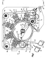
- a dunnage formation machine is shown generally at 10.
- the machine includes a rotatable drum 12 which is driven by a motor 14 via a gear box 15 and a belt and pulley arrangement 16, Figure 2.
- the drum is comprised of spaced annular disks 18.
- a web 20 is fed from a supply, not shown. As is best seen in Figure 1, the web 20 passes over a guide roll 22 and thence under a guide roll 24 to an inflation station 25. The web 20 is fed around the disks 18 to pass under, in the disclose embodiment, three heat shoes 26 which shoes heat metal transport belts 27 to seal layers of the web. The heat softened web portions and the transport belts then pass under cooling shoes 28 which freeze the seals being formed. As the now inflated and sealed web passes from the cooling shoes individual dunnage units 30 are dispensed.
- the machine 10 will be housed within a cabinet which is not shown for clarity of illustration.
- the cabinet includes access doors with an electrical interlock. When the doors are open the machine may be jogged for set up, but the machine will not operate to produce dunnage units unless the doors are closed and latched.
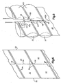
- the web is formed of a heat sealable plastic such as polyethylene.
- the web includes superposed top and bottom layers connected together at spaced side edges 32. Each of the side edges is a selected one of a fold or a seal such that the superposed layers are hermetically connected along the side edges 32.
- each transverse seal extends from an associated side edge 32 toward a longitudinally extending pair of lines of weakness 35.
- the longitudinal lines of weakness 35 are superposed one over the other in the top and bottom layers of the web and are located midway between the side edges.
- Each transverse seal 34 terminates in spaced relationship with the longitudinal lines of weakness which preferably are in the form of uniform, small perforations.
- the transverse seal pairs 34 together with the side edges 32 delineate two chains of centrally open side connected, inflatable pouches 37.
- transverse lines of weakness 36 are provided.
- the pouches are separable along the transverse lines 36.
- the transverse lines are preferably perforations but in contrast to the to the longitudinal line perforations each has substantial length.
- the perforations of the transverse lines 36 in a further contrast with the perforations of the longitudinal lines 35, are not of uniform dimension longitudinally of the lines. Rather, as is best seen in Figure 8, a pair of small or short perforations 38 is provided in each line. The small perforations 38 of each pair are disposed on opposite sides of and closely spaced from the longitudinal lines 34.
- Each transverse line of weakness also includes a pair of intermediate length perforations 40 which are spaced and positioned on opposite sides of the small perforations 38.
- the intermediate perforations extend from unsealed portions of the superposed layers into the respective seals of the associated transverse seal pair. The remaining perforations of each line are longer than the intermediate perforations 40.
- the disks 18 are mounted on a tubular shaft 42.
- the shaft 42 is journaled at 44 for rotation driven by the belt and pulley arrangement 16.
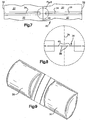
- the shaft 42 carries a stationary, tubular, nozzle support 45 which extends from around the shaft 42 radially outwardly.
- a nozzle assembly 46 is carried by a support arm 45A, Figure 6.
- the nozzle assembly 46 includes an inflation nozzle 48.
- the nozzle 48 is an elongated tube with a closed, generally conical, lead end portion 49.
- the nozzle 48 when in use extends into the web at a central location transversely speaking.
- the web transverse lines of weakness are spaced slightly more than a one half the circumference of the nozzle so that the web layers fit closely around the nozzle to minimize leakage of air exiting side passages 51 of the nozzle to inflate the pouches 37.
- the nozzle assembly 46 includes a web retainer 50 which guides the web against the nozzle 48.
- the retainer also functions to cause the web to be longitudinally split along the longitudinal lines of weakness 35 into two strips of inflated pouches.
- each of the heat shoes 26 has a mirror image pair of heat conductive bodies 52.
- the bodies 52 together define a cylindrical aperture 54, which houses a heating element, not shown.
- Each heat body 52 includes a seal leg 55 having an arcuate surface substantially complemental with a cylindrical surface of an associated one of the disks 18.
- the disk surfaces are defined by thermally conductive silicone rubber inserts 18s, Figure 3A.
- springs 56 bias the legs 55 against the transport belts 27 as the web passes under the heat shoes due to rotation of the drum 12 and its disks 18.
- the cooling shoes 38 are mounted identically to the heat shoes.
- Each cooling shoe 28 includes an expansion chamber 58, Figure 4.
- An air supply not shown, is connected to a chamber inlet 60. Air under pressure is fed through the inlet 60 into the chamber 58 where the air expands absorbing heat and thus cooling the shoe. Exhaust air from the chamber passes through an exit 62. Cooling shoe legs 63 are biased against the web to freeze the heat softened plastic and complete seals.
- cooling shoe exhaust air then passes through a conduit 64 to the tubular shaft 42. Air from the cooling shoes is fed via the conduit 64 and the shaft 42 to a passage 65 in the nozzle support 45. The passage 65 is connected to the nozzle 48. Thus air from the cooling shoes is directed to and through the nozzle 48 and the exit passages 51 into the pouches.
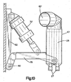
- cooling shoes 28' as shown in Figure 10 are employed has a jacket 67 which surrounds a body having cooling fins shown in dotted lines in Figure 10.
- An inlet 60' is provided at the top of the jacket. Air flowing from the inlet passes over the fins cooling them and the exits from the bottom of the jacket.
- Each of the shoes 28' is vented to atmosphere through an outlet 67.
- the nozzle 48 is directly connected to a supply of fluid under pressure and the shaft 42 may be made of solid material.
- a pair of hold down belts 66 are mounted on a set of pulleys 68.
- the belts 66 are reeved around a major portion of the disks 18.
- the belts 66 function to clamp portions of the web 20 against the disks on opposite sides of the shoe legs 55. While test have shown that the machine is fully operable without the belts 66, they are optionally provided to isolate pressurized air in the inflated pouches 37 from the heating and cooling shoes.
- a fixed separator 69 is provided. As the inflated pouches approach the exit from the downstream cooling shoe the fixed separator functions to cam them radially outwardly sequentially to separate each dunnage unit from the next trailing unit along the connecting transverse line of weakness except for a small portion under the transport belts 27.
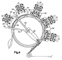
- a separator wheel 74 is provided, Figure 1.
- the wheel 74 is rotated clockwise as seen in Figure 1 such that arms 76 are effective to engage completed dunnage units 30 sequentially to complete the separation of each dunnage unit from the web along its trailing transverse line of weakness 36.
- the separator wheel is effective to tear the last small connection of each pouch which was under an associated one of the transport belts as the pouch was substantially separated by the fixed separator 69.
- each of the shoes 26, 28 is mounted on an associated radially disposed shaft 71.
- Clamping arrangements shown generally at 72 are provided to fix each of the shafts 71 in an adjusted position radially of and relative to the drum 12.
- each shaft 71 carries a yoke 73.
- the springs 56 span between yoke pins 75 and shoe pins 75 to bias the shoes against a web 20.
- a cylinder 70 is provided for elevating a connected yoke and shoe for machine set up and service.
- each shoe is pivotally mounted on an arm 78.
- the arm is also pivotally mounted at 80 on a frame 82.
- a cylinder 70' spans between the arm and the frame for elevating the connected shoe for set up and service and for urging the shoes 28 into their operating positions.
- the heat shoes 26 are, in the now preferred arrangement, identically mounted.
- the shoes are elevated by energizing the cylinders 70 of Figures 1 and 4 or 70' of Figure 10.
- a web 20 is fed along a path of travel over the guide roll 22 and under the guide roll 24 and thence threaded over the inflation nozzle 48.
- the web is then fed under the transport belts and the retainer 50.
- the web is split by the nozzle support 55.
- the split of the web is along the longitudinal line of weakness but the transverse lines of weakness remain intact at this time.
- the web portions at opposite ends of the small perforations 38 are of sufficient size and strength to avoid a longitudinal split of the web as the web is fed over the nozzle. Since the transverse seals of each pair are spaced only very slightly more than one half the circumference of the nozzle the web closely surrounds the nozzle to minimize air leakage when the pouches are inflated.
- the heating and cooling shoes are elevated by actuating either the cylinders 70 or 70'.
- the web is then fed sequentially, and one at a time, under the heating shoes 26 and the cooling shoes 28. Since the web has been split by the nozzle support 55, there are in fact two parallel paths of travel each with an associated transport belt 27 and chain of side connected and inflated pouches.
- the heat shoe elements will be energized. Air will be supplied to the cooling shoes 28 and the nozzle 48. Next the motor 14 will be energized to commence machine operation.
- one of the outstanding features of the invention is that the web closely surrounds and slides along the nozzle. The close surrounding is assured by the transverse seals being spaced a distance substantially equal to one half the circumference of the nozzle 48.
- the two web layers together delineate a nozzle receiving space which will closely surround an inserted nozzle.
- the pouches 37 on opposed sides of the nozzle will be filled efficiently by fluid under pressure exiting the nozzle passages 51 in opposed streams. Where dunnage units are being formed the fluid will be air.
- the web is then split by the nozzle support into two chains of side connected and fluid filled pouches respectively traveling along associated ones of the two paths of travel.
- Each of the chains is fed under spaced legs 55 of the heating shoes 26 to effect heat seals.
- the seals are frozen and the pouches are separated along most of the length of transverse lines of weakness by the separator. Facile separation is assured by the long perforations because the remaining connections of the web across the transverse seals are short in transverse dimension and few in number.
- the pouches exit the last of the cooling shoes, they have been formed into finished dunnage units 30.
- the finished units 30 are sequentially completely separated from the web by the arms 76 of the separation wheel 74.
Abstract
Description
- This invention relates to machines and processes for producing dunnage and other fluid filled units.
- U.S. Patents Re 36,501 reissued January 18, 2000 and RE 36,759 reissued July 4, 2000 respectively entitled "Method for Producing Inflated Dunnage" and "Inflated Dunnage and Method for its Production" and based on original patents respectively issued September 3, 1996 and December 2, 1997 to Gregory A. Hoover et al. (the Hoover Patents) disclose a method for producing dunnage utilizing preopened bags on a roll. The preopened bags utilized in the Hoover patents are of a type disclose in U.S. Patent 3,254,828 issued June 2, 1996 to Hershey Lerner and entitled "Flexible container Strips" (the Autobag patent). The preferred bags of the Hoover patents are unique in that the so called tack of outer bag surfaces is greater than the tack of the inner surfaces to facilitate bag opening while producing dunnage units which stick to one another when in use.
- Patent 6,199,349 issued March 13, 2001 under the title Dunnage Material and Process (the Lerner Patent) discloses a chain of interconnected plastic pouches which are fed along a path of travel to a fill and seal station. As each pouch is positioned at the fill station the pouches are sequentially opened by directing a flow of air through a pouch fill opening to open and then fill the pouch. Each filled pouch is then sealed to create an hermetically closed, inflated dunnage unit. Improvements on the pouches of the Lerner Patent are disclose in copending applications serial no. 09/735,345 filed December 12, 2000 and serial no. 09/979,256 filed November 21, 2001 and respectively is entitled Dunnage Inflation (the Lerner Applications). The system of the Lerner Patent and Applications is not suitable for packaging liquids. Moreover, since the production of dunnage units by the process described is relatively slow, and accumulator is desirable. An improved accumulator and dispenser for receiving dunnage units manufactured by a dunnage unit Formation machine is disclose in U.S. Application Serial No. 09/735,111 filed December 12, 2000 by Rick S. Wehrmann under the title Apparatus and Process for Dispensing Dunnage.
- Accordingly, it would be desirable to provide an improved system for filing pouches with fluid to produce with fluid to produce dunnage or liquid filled units at high rates of speed.
- According to one aspect of this invention, there is provided a forming machine for making fluid filled units comprising:
- a) a rotatable drum including a spaced pair of cylindrical work piece supporting surfaces;
- b) coacting means for pressing work pieces against the surfaces;
- c) heating and cooling shoes operably connected to the drum at a sealing station and coactable with the belt and surfaces for sealing a plastic web held between the belts and the drum;
- d) a supply line for gas under pressure connected to the cooling shoe for effecting cooling by allowing expansion of the supplied gas in a chamber in the cooling shoe;
- e) a fluid nozzle positioned upstream from the shoes in a direction opposite drum rotation for fluid filling pouches in such web as such web is fed from a supply to the sealing station; and
- f) characterized by the nozzle having fluid exit ports disposed in opposite sides of the nozzle for emitting pouch filling in opposed directions into pouches spaced axially of the drum.
-
- According to another aspect of this invention, there is provided a process of forming fluid filled units comprising:
- a) feeding a web having a series of side connected pouches from a supply to a fill station;
- b) fluid filling the pouches as the web is fed through the fill station by directing fluid under pressure through a fill nozzle into the web pouches;
- c) sealing the pouches to form filled units by engaging the web with a moving support cylndrical surface surface and passing engaged web portions under coacting heating and cooling shoes each having arcuate surfaces complemental with the support; and
- d) characterized by maintaining the web in close surrounding relationship with the nozzle during the filling step to limit the loss of fluid under pressure from the web.
-
- The machine and process of the preferred embodiment provide enhanced production of dunnage units similar to those produced by the systems of the Lerner Patent and Applications but at greatly improved production rates. Unlike those systems, the machine and process of the preferred embodiment are also capable of producing liquid filled units. Specifically, an improved forming machine for making fluid filled units is disclosed. The preferred embodiment of the machine includes a rotatable drum having a spaced pair of cylindrically contoured surfaces. An elongated nozzle may extend generally tangentially between and from the cylindrical surfaces. In use, the nozzle may be inserted into a web at a transversely centered position as the web is fed upwardly and around the drum. The web is described and claimed in a concurrently filed application. In the preferred embodiment, as the web passes over the nozzle, web pouches are filled with fluid and the web is separated into two chains of filled pouches as the nozzle assembly separates the web along longitudinal lines of weakness.
- A plurality of heat shoes may be provided. Each heat shoe may have a spaced pair of arcuate web engaging surfaces which may be complemental with the cylindrical drum surfaces. Downstream from the heat shoes in the direction of web travel, a plurality of cooling shoes may be provided. The cooling shoes like the heating shoes may have pairs of arcuate surfaces which may be complemental with the drum's cylindrical surfaces. The shoes may be effective to clamp a pair of metal transport belts against the web and in turn the web against the rotating drum as spaced sets of seals are formed. The seals may complete fluid filled pouches and may convert the filled pouches into dunnage or liquid filled units. The units may be separated following their exit from the last of the cooling shoes.
- Tests of dunnage manufacture have shown that with pouches having four inch square external dimensions, dunnage units may be produced at the rate of eight cubic feet per minute. This contrasts sharply with the machine of the Lerner Patents which produces dunnage units at the rate of three cubic feet per minute. Indeed the system of the preferred embodiment produces dunnage units on demand at rates sufficiently fast to obviate the need for a device such as that taught in The Dispenser Patent.
- One of features of a dunnage only embodiment of the machine of the preferred embodiment is efficient way in which it utilizes air under pressure. Pressurized air may be fed to chambers within the cooling shoes where it may be allowed to expand. As the air expands in the cooling shoe chambers, it may absorb heat, enabling the shoes effectively to freeze seals of dunnage units being formed.
- The drum in the disclosed embodiments is in fact a slightly spaced pair of disks mounted on a driven rotatable shaft. In the dunnage only embodiment the drum shaft is tubular. Air exhausted from the cooling shoes may be fed to the tubular shaft and thence through an axially centered shaft outlet to a connected nozzle. Air supplied to the nozzle may further expand as the pouches are inflated. In the preferred embodiment, the result is even though the air expands as pouches are inflated, the air within the pouches may be warmer than ambient. In this embodiment, as the air within the pouches, and thus the dunnage units being formed reaches equilibrium with the ambient temperature, pressure within the units will decrease sufficiently to assure that the finished dunnage units, while solidly filled, are filled at controlled pressure low enough to minimize the potential for rupture when compressed in use.
- Accordingly advantages of the preferred embodiment are that it provides an improved dunnage formation machine and process of formation of fluid filled units.
-
- Figure 1 is an elevational view of the unit formation machine of the present invention;
- Figure 2 is a plan view of the machine of Figure 1 as seen from the plane indicated by the line 2-2 of Figure 1 showing a web being fed into the machine;
- Figure 3 is an enlarged sectional view of a heat shoe and a portion of the drum as seen from the plane indicated by the line 3-3 of Figure 1;
- Figure 3a is a further enlarged view of the shoe and the drum as seen from the same plane as Figure 3;
- Figure 4 is a view showing a dunnage embodiment of the machine with components which delineate a air flow path from a supply to and through the cooling shoes and then the inflation nozzle;
- Figure 5 is a perspective view of a section of the novel and improved web;
- Figure 6 is a perspective view showing a section of a web as the web pouches are inflated and the web is separated into parallel rows of inflated pouches;
- Figure 7 is an enlarged plan view of a portion of the web including a transverse pair of heat seals;
- Figure 8 is a further enlarged fragmentary view of a central part of the web as located by the circle in Figure 7;
- Figure 9 is a perspective view showing a pair of completed fluid filled units following separation and as they exit the machine; and,
- Figure 10 is an enlarged view of a preferred support embodiment and a shoe which arrangement is for supporting the shoes in their use positions and for moving them to out of the way positions for machine set up and service.
-
- While the following description describes a dunnage formation system, it should be recognized the preferred embodiment of the machine is sterilzable so that beverages such as water and fruit juice may be packaged using the novel web, machine and process.
- Referring now to the drawings and Figures 1 and 2 in particular, a dunnage formation machine is shown generally at 10. The machine includes a
rotatable drum 12 which is driven by amotor 14 via agear box 15 and a belt andpulley arrangement 16, Figure 2. In the preferred and disclose arrangement, the drum is comprised of spacedannular disks 18. - When the machine is in use a
web 20 is fed from a supply, not shown. As is best seen in Figure 1, theweb 20 passes over aguide roll 22 and thence under aguide roll 24 to aninflation station 25. Theweb 20 is fed around thedisks 18 to pass under, in the disclose embodiment, threeheat shoes 26 which shoes heatmetal transport belts 27 to seal layers of the web. The heat softened web portions and the transport belts then pass under coolingshoes 28 which freeze the seals being formed. As the now inflated and sealed web passes from the cooling shoesindividual dunnage units 30 are dispensed. - In practice the
machine 10 will be housed within a cabinet which is not shown for clarity of illustration. The cabinet includes access doors with an electrical interlock. When the doors are open the machine may be jogged for set up, but the machine will not operate to produce dunnage units unless the doors are closed and latched. - Referring now to Figures 5-9, the novel and improved web for forming dunnage units is disclose. The web is formed of a heat sealable plastic such as polyethylene. The web includes superposed top and bottom layers connected together at spaced side edges 32. Each of the side edges is a selected one of a fold or a seal such that the superposed layers are hermetically connected along the side edges 32.
- A plurality of transverse seal pairs 34 are provided. As best seen in Figures 5-7, each transverse seal extends from an associated
side edge 32 toward a longitudinally extending pair of lines ofweakness 35. The longitudinal lines ofweakness 35 are superposed one over the other in the top and bottom layers of the web and are located midway between the side edges. Eachtransverse seal 34 terminates in spaced relationship with the longitudinal lines of weakness which preferably are in the form of uniform, small perforations. The transverse seal pairs 34 together with the side edges 32 delineate two chains of centrally open side connected,inflatable pouches 37. - As is best seen in Figures 7 and 8, transverse lines of
weakness 36 are provided. The pouches are separable along thetransverse lines 36. Like the longitudinal lines ofweakness 35 the transverse lines are preferably perforations but in contrast to the to the longitudinal line perforations each has substantial length. The perforations of thetransverse lines 36, in a further contrast with the perforations of thelongitudinal lines 35, are not of uniform dimension longitudinally of the lines. Rather, as is best seen in Figure 8, a pair of small orshort perforations 38 is provided in each line. Thesmall perforations 38 of each pair are disposed on opposite sides of and closely spaced from thelongitudinal lines 34. Each transverse line of weakness also includes a pair ofintermediate length perforations 40 which are spaced and positioned on opposite sides of thesmall perforations 38. The intermediate perforations extend from unsealed portions of the superposed layers into the respective seals of the associated transverse seal pair. The remaining perforations of each line are longer than theintermediate perforations 40. - In the embodiment of Figure 1, the
disks 18 are mounted on atubular shaft 42. Theshaft 42 is journaled at 44 for rotation driven by the belt andpulley arrangement 16. Theshaft 42 carries a stationary, tubular,nozzle support 45 which extends from around theshaft 42 radially outwardly. Anozzle assembly 46 is carried by a support arm 45A, Figure 6. Thenozzle assembly 46 includes aninflation nozzle 48. As is best seen in Figure 6, thenozzle 48 is an elongated tube with a closed, generally conical,lead end portion 49. Thenozzle 48 when in use extends into the web at a central location transversely speaking. The web transverse lines of weakness are spaced slightly more than a one half the circumference of the nozzle so that the web layers fit closely around the nozzle to minimize leakage of air exitingside passages 51 of the nozzle to inflate thepouches 37. - The
nozzle assembly 46 includes aweb retainer 50 which guides the web against thenozzle 48. The retainer also functions to cause the web to be longitudinally split along the longitudinal lines ofweakness 35 into two strips of inflated pouches. - As is best seen in Figures 3 and 3A, each of the heat shoes 26 has a mirror image pair of heat
conductive bodies 52. Thebodies 52 together define acylindrical aperture 54, which houses a heating element, not shown. Eachheat body 52 includes aseal leg 55 having an arcuate surface substantially complemental with a cylindrical surface of an associated one of thedisks 18. In the disclose embodiment the disk surfaces are defined by thermally conductive silicone rubber inserts 18s, Figure 3A. In the embodiment of Figures 3 and 3A, springs 56 bias thelegs 55 against thetransport belts 27 as the web passes under the heat shoes due to rotation of thedrum 12 and itsdisks 18. The cooling shoes 38 are mounted identically to the heat shoes. - Each cooling
shoe 28 includes anexpansion chamber 58, Figure 4. An air supply, not shown, is connected to achamber inlet 60. Air under pressure is fed through theinlet 60 into thechamber 58 where the air expands absorbing heat and thus cooling the shoe. Exhaust air from the chamber passes through anexit 62. Cooling shoe legs 63 are biased against the web to freeze the heat softened plastic and complete seals. - In the embodiment of Figures 1-4 cooling shoe exhaust air then passes through a
conduit 64 to thetubular shaft 42. Air from the cooling shoes is fed via theconduit 64 and theshaft 42 to apassage 65 in thenozzle support 45. Thepassage 65 is connected to thenozzle 48. Thus air from the cooling shoes is directed to and through thenozzle 48 and theexit passages 51 into the pouches. - With the now preferred and sterilizable embodiment, cooling shoes 28' as shown in Figure 10 are employed has a
jacket 67 which surrounds a body having cooling fins shown in dotted lines in Figure 10. An inlet 60'is provided at the top of the jacket. Air flowing from the inlet passes over the fins cooling them and the exits from the bottom of the jacket. Each of the shoes 28' is vented to atmosphere through anoutlet 67. Thenozzle 48 is directly connected to a supply of fluid under pressure and theshaft 42 may be made of solid material. - A pair of hold down
belts 66 are mounted on a set ofpulleys 68. Thebelts 66 are reeved around a major portion of thedisks 18. As is best seen in Figures 3 and 3A, thebelts 66 function to clamp portions of theweb 20 against the disks on opposite sides of theshoe legs 55. While test have shown that the machine is fully operable without thebelts 66, they are optionally provided to isolate pressurized air in theinflated pouches 37 from the heating and cooling shoes. - A fixed
separator 69 is provided. As the inflated pouches approach the exit from the downstream cooling shoe the fixed separator functions to cam them radially outwardly sequentially to separate each dunnage unit from the next trailing unit along the connecting transverse line of weakness except for a small portion under thetransport belts 27. - A
separator wheel 74 is provided, Figure 1. Thewheel 74 is rotated clockwise as seen in Figure 1 such thatarms 76 are effective to engage completeddunnage units 30 sequentially to complete the separation of each dunnage unit from the web along its trailing transverse line ofweakness 36. Thus, the separator wheel is effective to tear the last small connection of each pouch which was under an associated one of the transport belts as the pouch was substantially separated by the fixedseparator 69. - In the embodiment of Figure 1, each of the
shoes shaft 71. Clamping arrangements shown generally at 72 are provided to fix each of theshafts 71 in an adjusted position radially of and relative to thedrum 12. As is best seen in Figure 3, eachshaft 71 carries ayoke 73. Thesprings 56 span between yoke pins 75 and shoe pins 75 to bias the shoes against aweb 20. Acylinder 70 is provided for elevating a connected yoke and shoe for machine set up and service. - In the now preferred embodiment of Figure 10, each shoe is pivotally mounted on an
arm 78. The arm is also pivotally mounted at 80 on aframe 82. A cylinder 70' spans between the arm and the frame for elevating the connected shoe for set up and service and for urging theshoes 28 into their operating positions. The heat shoes 26 are, in the now preferred arrangement, identically mounted. - In operation, the shoes are elevated by energizing the
cylinders 70 of Figures 1 and 4 or 70' of Figure 10. Aweb 20 is fed along a path of travel over theguide roll 22 and under theguide roll 24 and thence threaded over theinflation nozzle 48. The web is then fed under the transport belts and theretainer 50. As the machine is jogged to feed the web around thediscs 18 and the heating andcooling shoes nozzle support 55. The split of the web is along the longitudinal line of weakness but the transverse lines of weakness remain intact at this time. Thus, the web portions at opposite ends of thesmall perforations 38 are of sufficient size and strength to avoid a longitudinal split of the web as the web is fed over the nozzle. Since the transverse seals of each pair are spaced only very slightly more than one half the circumference of the nozzle the web closely surrounds the nozzle to minimize air leakage when the pouches are inflated. - Next the heating and cooling shoes are elevated by actuating either the
cylinders 70 or 70'. The web is then fed sequentially, and one at a time, under the heating shoes 26 and the cooling shoes 28. Since the web has been split by thenozzle support 55, there are in fact two parallel paths of travel each with an associatedtransport belt 27 and chain of side connected and inflated pouches. - Once the web has been fed around the drum to an exit location near the
separator wheel 74 and the machine has been jogged until the operator is satisfied the feed is complete and the machine is ready. the heat shoe elements will be energized. Air will be supplied to the cooling shoes 28 and thenozzle 48. Next themotor 14 will be energized to commence machine operation. - As we have suggested, one of the outstanding features of the invention is that the web closely surrounds and slides along the nozzle. The close surrounding is assured by the transverse seals being spaced a distance substantially equal to one half the circumference of the
nozzle 48. Thus, the two web layers together delineate a nozzle receiving space which will closely surround an inserted nozzle. As the web advances thepouches 37 on opposed sides of the nozzle will be filled efficiently by fluid under pressure exiting thenozzle passages 51 in opposed streams. Where dunnage units are being formed the fluid will be air. The web is then split by the nozzle support into two chains of side connected and fluid filled pouches respectively traveling along associated ones of the two paths of travel. - Each of the chains is fed under spaced
legs 55 of the heating shoes 26 to effect heat seals. As the web passes under cooling shoe legs 63 the seals are frozen and the pouches are separated along most of the length of transverse lines of weakness by the separator. Facile separation is assured by the long perforations because the remaining connections of the web across the transverse seals are short in transverse dimension and few in number. - When the pouches exit the last of the cooling shoes, they have been formed into
finished dunnage units 30. Thefinished units 30 are sequentially completely separated from the web by thearms 76 of theseparation wheel 74. - While the system as disclosed and described in the detailed description is directed to dunnage, again, as previously indicated, units filled with fluids other than than air such as water and fruit juices can be produced with the same machine machine, process and web.
- Although the invention has been described in its preferred form with a certain degree of particularity, it is understood that the present disclosure of the preferred form has been made only by way of example and that numerous changes in the details of construction, operation and the combination and arrangement of parts may be resorted to without departing from the spirit and the scope of the invention as hereinafter claimed.
- Whilst endeavouring in the foregoing specification to draw attention to those features of the invention believed to be of particular importance it should be understood that the Applicant claims protection in respect of any patentable feature or combination of features hereinbefore referred to and/or shown in the drawings whether or not particular emphasis has been placed thereon.
Claims (28)
- A forming machine for making fluid filled units comprising:a) a rotatable drum including a spaced pair of cylindrical work piece supporting surfaces;b) coating means for pressing work pieces against the surfaces;c) heating and cooling shoes operably connected to the drum at a sealing station and coactable with the belt and surfaces for sealing a plastic web held between the belts and the surfaces as the web is fed under the shoes by the belts and the drum;d) a supply line for gas under pressure connected to the cooling shoe for effecting cooling by allowing expansion of the supplied gas in a chamber in the cooling shoe;e) a fluid nozzle positioned upstream from the shoes in a direction opposite drum rotation for fluid filling pouches in such web as such web is fed from a supply to the sealing station; andf) characterized by the nozzle having fluid exit ports disposed in opposite sides of the nozzle for emitting pouch filling in opposed directions into pouchss spaced axially of the drum.
- A machine according to claim 1 wherein the fluid is a gas and further including a further supply line connecting an outlet from the cooling shoe chamber to the nozzle for supplying gas to the nozzle.
- A machine according to claim 1 or claim 2 further including a separator down stream from the station for separating each of formed units from the web.
- A machine according to any of claims 1-3 wherein each shoe has a spaced pair of tracks each coactable with an associated belt whereby to concurrently seal pairs of oppositely directed pouches when the machine is in use.
- A machine according to claim 4 wherein the tracks are arcuate.
- A machine according to any of the preceding claims wherein the drum is rotatable wheel having a pair of closely spaced, relatively narrow, cylindrical , web engaging surfaces, the surfaces being axially spaced.
- A machine according to claim 6 wherein the heating and cooling shoes each have a spaced pair of arcuate, belt engaging surfaces, each of the shoe surfaces being in closely spaced concentric relationship with an associated belt and an associated wheel surface along a web feed path for effecting seals in multi-layered webs transported by the belts and the wheel in engagement with each of the surfaces.
- A machine according to any of the preceding claims wherein the nozzle has a cylindrical section and a generally conical tip, the section including opposed sets of axially spaced exit apertures for directing fluid under pressure into opposed and spaced pairs of pouches.
- A machine according to any of the preceding claims wherein the nozzle is sized for close insertion into a surrounding web.
- A machine according to any of claims 6 to 9 wherein the belts, the wheel and the shoe surfaces define axially spaced pairs of path segments whereby the machine is configured such that the segments form a spaced pair of seals in a web transported by wheel rotation.
- A machine according to any of the preceding claims further including an air supply connected to the cooling shoes and communicating with air expansion spaces each within an associated one of the cooling shoes.
- A machine according to claim 11 wherein a further conduit is connected to an outlet from at least one of the cooling shoe spaces and to the nozzle whereby to provide, pouch inflating air to a web when the machine is in use to form dunnage units.
- A machine according to any of the preceding claims wherein the drum is comprised of an axially spaced pair of discs and the nozzle is mounted generally tangentially of the drum with an elongate body intersected by an imaginary plane normal to said axis at a location midway between the discs.
- A machine according to any of the preceding claims wherein the drum is mounted on a hollow shaft and the cooling shoe has an outlet in communication with the nozzle via the hollow shaft.
- A machine according to any of the preceding claims wherein a web retainer is connected to the nozzle for maintaining the web substantially in contact with the nozzle when the machine is not in use.
- machine according to any of the preceding claims wherein the nozzle and the retainer are parts of a nozzle assembly, the assembly being adapted to separate a web along longitudinal line of weakness in the web to form two webs each of side connected fillable pouches.
- A process of forming fluid filled units comprising:a) feeding a web having a series of side connected pouches from a supply to a fill station;b) fluid filling the pouches as the web is fed through the fill station by directing fluid under pressure through a fill nozzle into the web pouches;c) sealing the pouches to form filled units by engaging the web with a moving support cylindrical surface and passing engaged web portions under coacting heating and cooling shoes each having arcuate surfaces complemental with the support; andd) characterized by maintaining the web in close surrounding relationship with the nozzle during the filling step to limit the loss of fluid under pressure from the web.
- A process according to claim 17 wherein the support surface is in the form of a rotating drum and the sealing step is effected by feeding the web from the fill station around the drum.
- A process according to claim 17 or 18 wherein the fluid is air and the cooling shoe is cooled by allowing air under pressure to expand in a chamber within the cooling shoe.
- A process according to claim 19 wherein output from the cooling shoe is fed to the nozzle whereby to inflate the pouches with air at temperatures warmer than air ambient to dunnage units being formed.
- A process according to any of claims 17-20 wherein there are spaced pairs of side connected pouches and the pouches of each pair are concurrently formed into dunnage units.
- A process according to any of claims 16-21 including the steps of inserting the fill nozzle into a space between two layers of a plastic web in which spaced pairs of transverse pairs of seals delineate the sides of the space, the transverse dimension of the space when flattened being slightly greater than one half the circumference of the fill nozzle whereby the inserted nozzle is closely surrounded by the two layers.
- A process according to claim 22 wherein the web is separated into spaced chains of filled pouches following the filling step by engaging a longitudinal line of weakness in the web as it is advanced.
- A process according to claim 23 wherein the step of engaging the longitudinal line of weakness is performed by engaging the web with a nozzle support.
- A process according to claim 23 or 24 wherein the chains respectively engage spaced discs and are fed by the discs and coacting heat transfer belts under heating and cooling shoes to perform the sealing step.
- A process according to any of claims 17 to 25 wherein the nozzle has a generally cylindrical section with spaced rows of opposed air outlets for inflating the transversely spaced pouches which pouches are arranged in transversely spaced rows.
- A process according to any of the preceding claims wherein each completed unit is substantially separated along its trailing transverse perforations while a seal portion of the trailing unit is between an associated transport belt and an associated disc.
- A process according to claim 27 wherein the substantial separation is accomplished by passing the filled pouches over a fixed separator.
Applications Claiming Priority (2)
| Application Number | Priority Date | Filing Date | Title |
|---|---|---|---|
| US10/408,947 US6889739B2 (en) | 2003-04-08 | 2003-04-08 | Fluid filled unit formation machine and process |
| US408947 | 2003-04-08 |
Publications (3)
| Publication Number | Publication Date |
|---|---|
| EP1466720A2 true EP1466720A2 (en) | 2004-10-13 |
| EP1466720A3 EP1466720A3 (en) | 2006-05-24 |
| EP1466720B1 EP1466720B1 (en) | 2019-06-12 |
Family
ID=32869186
Family Applications (1)
| Application Number | Title | Priority Date | Filing Date |
|---|---|---|---|
| EP04252036.1A Expired - Lifetime EP1466720B1 (en) | 2003-04-08 | 2004-04-06 | Process for forming fluid filled units and series of fluid filled units |
Country Status (5)
| Country | Link |
|---|---|
| US (4) | US6889739B2 (en) |
| EP (1) | EP1466720B1 (en) |
| CA (1) | CA2463389C (en) |
| ES (1) | ES2744812T3 (en) |
| MX (1) | MXPA04003279A (en) |
Cited By (12)
| Publication number | Priority date | Publication date | Assignee | Title |
|---|---|---|---|---|
| WO2007070240A1 (en) * | 2005-12-12 | 2007-06-21 | Automated Packaging Systems, Inc. | Web and method for making fluid filled units |
| US7571584B2 (en) | 2004-06-01 | 2009-08-11 | Automated Packaging Systems, Inc. | Web and method for making fluid filled units |
| US7718028B2 (en) | 2003-04-08 | 2010-05-18 | Automated Packaging Systems, Inc. | Fluid filled unit formation process |
| US7757459B2 (en) | 2004-06-01 | 2010-07-20 | Automated Packaging Systems, Inc. | Web and method for making fluid filled units |
| US7767288B2 (en) | 2003-04-08 | 2010-08-03 | Automated Packaging Systems, Inc. | Web for fluid filled unit formation |
| USD630945S1 (en) | 2009-02-27 | 2011-01-18 | Automated Packaging Systems, Inc. | Inflatable packing material |
| US8354150B2 (en) | 2007-10-31 | 2013-01-15 | Automated Packaging Systems, Inc. | Web and method for making fluid filled units |
| US9205622B2 (en) | 2009-02-27 | 2015-12-08 | Automated Packaging Systems, Inc. | Web and method for making fluid filled units |
| US9266300B2 (en) | 2011-07-07 | 2016-02-23 | Automated Packaging Systems, Inc. | Air cushion inflation machine |
| US9844911B2 (en) | 2013-11-21 | 2017-12-19 | Automated Packaging Systems, Inc. | Air cushion inflation machine |
| CN111070703A (en) * | 2020-01-03 | 2020-04-28 | 陈海华 | Automatic production process of sphygmomanometer pressurization air bag |
| US10647460B2 (en) | 2013-03-15 | 2020-05-12 | Automated Packaging Systems, Llc | On-demand inflatable packaging |
Families Citing this family (43)
| Publication number | Priority date | Publication date | Assignee | Title |
|---|---|---|---|---|
| US20030095696A1 (en) * | 2001-09-14 | 2003-05-22 | Reeves Anthony P. | System, method and apparatus for small pulmonary nodule computer aided diagnosis from computed tomography scans |
| GB2387423B (en) * | 2002-04-12 | 2005-06-22 | Green Light Packaging Ltd | Apparatus and method for forming void-fill packaging |
| AU2005203038A1 (en) * | 2004-07-15 | 2006-02-02 | Sealed Air Corporation (Us) | High-speed apparatus and method for forming inflated chambers |
| US7578333B2 (en) * | 2004-07-20 | 2009-08-25 | Pregis Corporation | Machine and methods for the manufacture of air-filled cushions |
| US8020358B2 (en) * | 2004-11-02 | 2011-09-20 | Sealed Air Corporation (Us) | Apparatus and method for forming inflated containers |
| US7165375B2 (en) * | 2005-02-05 | 2007-01-23 | Sealed Air Corporation (Us) | Inflation device for forming inflated containers |
| US7225599B2 (en) * | 2005-04-05 | 2007-06-05 | Sealed Air Corporation | Apparatus and method for forming inflated articles |
| US20090293427A1 (en) * | 2005-08-01 | 2009-12-03 | Automated Packaging Systems, Inc. | Web and method for making fluid filled units |
| US8157141B2 (en) * | 2006-06-14 | 2012-04-17 | Cryovac, Inc. | System and method for detecting and registering serrated bags |
| US8549822B2 (en) * | 2006-07-17 | 2013-10-08 | Automated Packaging Systems, Inc. | Packaging machine and process |
| PL2404833T3 (en) | 2006-10-04 | 2014-11-28 | Pregis Innovative Packaging | Automated air-pillow dispenser |
| AU2007334053B2 (en) * | 2006-12-15 | 2011-04-21 | Ccl Label Gmbh | Stretch film sleeve label applicator |
| US7503156B2 (en) * | 2007-01-11 | 2009-03-17 | Ralph Eibert | Method and apparatus for making dunnage |
| EP1978770A1 (en) * | 2007-04-05 | 2008-10-08 | Matsushita Electric Industrial Co., Ltd. | Management of mobile terminals in a communication system allowing for multiple-tracking area registration |
| US8567159B2 (en) | 2007-04-12 | 2013-10-29 | Sealed Air Corporation (Us) | Apparatus and method for making inflated articles |
| US7490449B1 (en) | 2007-08-13 | 2009-02-17 | Ralph Eibert | Method and apparatus for making dunnage |
| US9254940B2 (en) * | 2008-05-28 | 2016-02-09 | MaBelle Bray | Multi-compartment resealable storage bag and container |
| US20170021973A1 (en) * | 2008-05-28 | 2017-01-26 | MaBelle Bray | Multi-Compartment Resealable Storage Bag And Container |
| US7950433B2 (en) * | 2009-02-12 | 2011-05-31 | Sealed Air Corporation (Us) | Machine for inflating and sealing an inflatable web |
| EP2521648B1 (en) * | 2010-01-06 | 2019-02-27 | Pregis Innovative Packaging LLC | Packaging pillow device with upstream components |
| US9623622B2 (en) | 2010-02-24 | 2017-04-18 | Michael Baines | Packaging materials and methods |
| CH703963A2 (en) * | 2010-10-25 | 2012-04-30 | Guy Borgeat | Machine inflation automatic filling gas cushion, in particular air, for packaging, and its use to inflate and fill the bags. |
| SE535972C2 (en) * | 2011-06-22 | 2013-03-12 | Pronova Ab | Apparatus and method of packing goods in an inflatable bag |
| KR20160053944A (en) | 2013-09-10 | 2016-05-13 | 오토메이티드 패키징 시스템즈, 인코포레이티드 | Web for making fluid filled units |
| US10500808B2 (en) * | 2014-02-24 | 2019-12-10 | Pregis Innovative Packaging Llc | Inflation and sealing device with release features |
| WO2016044767A1 (en) * | 2014-09-19 | 2016-03-24 | Chan Simon Cs | Dunnage system |
| USD790231S1 (en) * | 2015-01-28 | 2017-06-27 | Hojeon Limited | Fabric |
| USD790230S1 (en) * | 2015-01-28 | 2017-06-27 | Hojeon Limited | Fabric |
| USD790229S1 (en) * | 2015-01-28 | 2017-06-27 | Hojeon Limited | Fabric |
| CN106079583B (en) * | 2015-05-22 | 2021-03-09 | 聂会平 | Operating system of air charging device of air buffer body and operating method thereof |
| CN107215006A (en) | 2016-03-21 | 2017-09-29 | 陈泽生 | Paper material, devices, systems, and methods needed for paper washer manufacturing system |
| WO2019161007A1 (en) | 2018-02-14 | 2019-08-22 | Automated Packaging Systems, Inc. | Methods and machines for making padded envelopes from on-demand inflatable packaging |
| BR112020016669A2 (en) | 2018-02-14 | 2020-12-15 | Pregis Innovative Packaging Llc. | INFLATION APPLIANCE AND BLANK SEAL |
| US10518497B2 (en) * | 2018-02-14 | 2019-12-31 | Pregis Innovative Packaging Llc | Heating device for a heating and sealing system |
| CN111902259B (en) * | 2018-02-14 | 2023-04-04 | 普里吉斯创新包装有限责任公司 | Device for forming protective packaging |
| US11065095B2 (en) | 2018-07-06 | 2021-07-20 | Instant Systems, Inc. | Sample container with peelable seal and access port |
| US11078001B2 (en) * | 2018-08-14 | 2021-08-03 | Pregis Innovative Packaging Llc | Inflatable packaging with tear initiation feature |
| EP3860831A4 (en) * | 2018-10-04 | 2023-06-07 | Automated Packaging Systems, LLC. | Air cushion inflation machine |
| EP3976499A1 (en) | 2019-06-03 | 2022-04-06 | Automated Packaging Systems, LLC. | On-demand inflatable packaging |
| US11890819B2 (en) * | 2021-03-24 | 2024-02-06 | Instant Systems, Inc. | Multi-chamber container for biological materials and compounded pharmaceuticals |
| EP4079649B1 (en) * | 2021-04-19 | 2023-12-27 | Fameccanica.Data S.p.A. | A dosing apparatus, and machine and method for producing unit dose articles |
| TWM617980U (en) * | 2021-07-23 | 2021-10-01 | 林浚瑋 | Improved structure of air pillar bag |
| CN117208349B (en) * | 2023-11-07 | 2024-01-19 | 山西柏生元生物技术有限公司 | Chinese-medicinal material packing processing apparatus |
Citations (4)
| Publication number | Priority date | Publication date | Assignee | Title |
|---|---|---|---|---|
| US3254828A (en) | 1963-12-18 | 1966-06-07 | Automated Packaging Corp | Flexible container strips |
| USRE36501E (en) | 1994-10-04 | 2000-01-18 | Hoover; Gregory A. | Method for producing inflated dunnage |
| USRE36759E (en) | 1994-10-04 | 2000-07-04 | Automated Packaging Systems, Inc. | Inflated dunnage and method for its production |
| US6199349B1 (en) | 1999-05-20 | 2001-03-13 | Automated Packaging Systems, Inc. | Dunnage material and process |
Family Cites Families (142)
| Publication number | Priority date | Publication date | Assignee | Title |
|---|---|---|---|---|
| US454180A (en) * | 1891-06-16 | mclennan | ||
| US329156A (en) * | 1885-10-27 | Combination square and gage | ||
| US3033257A (en) * | 1957-08-21 | 1962-05-08 | H G Weber And Company Inc | Bag forming tube and method of forming and accumulating the same |
| NL281183A (en) | 1962-07-19 | |||
| US3298156A (en) | 1964-01-07 | 1967-01-17 | Automated Packaging Corp | Method and apparatus for packaging |
| US3254820A (en) | 1964-06-15 | 1966-06-07 | Du Pont | Shock absorbing system for yarn delivery apparatus |
| US3389534A (en) | 1965-09-16 | 1968-06-25 | John M. Pendleton | Machine for making cushioning packaging material or the like |
| US3414140A (en) | 1966-08-01 | 1968-12-03 | Interlake Steel Corp | Dunnage |
| US3358823A (en) | 1967-01-16 | 1967-12-19 | Allen D Paxton | Gusset bottom bags in roll form and method of making same |
| US3477196A (en) | 1967-04-27 | 1969-11-11 | Automated Packaging Corp | Mechanism for automatically feeding,loading,and sealing bags |
| US3462027A (en) | 1967-08-14 | 1969-08-19 | Edmund C Puckhaber | Dunnage device |
| US3575757A (en) | 1967-12-08 | 1971-04-20 | Reinforced Air Corp | Process for making inflated articles |
| US3616155A (en) | 1968-06-26 | 1971-10-26 | Sealed Air Corp | Cellular laminate made from two thermoplastic sheets having polyvinylidene chloride coatings on facing sides of the sheets |
| US3523055A (en) | 1968-08-19 | 1970-08-04 | Jerome H Lemelson | Composite material,apparatus and method for producing same |
| US3577305A (en) * | 1968-08-22 | 1971-05-04 | Theodore G Hines | Thermal and air shock insulating structure |
| US3660189A (en) * | 1969-04-28 | 1972-05-02 | Constantine T Troy | Closed cell structure and methods and apparatus for its manufacture |
| US3575781A (en) * | 1969-05-16 | 1971-04-20 | Stauffer Hoechst Polymer Corp | Plastic film wrapping material |
| BE754395A (en) | 1969-08-04 | 1971-02-04 | Basf Ag | METHOD AND DEVICE FOR MAKING OR CLOSING BAGS BY WELDING PORTIONS OF THERMOPLASTIC SHEATH |
| US3650877A (en) * | 1969-10-06 | 1972-03-21 | Arpax Co | Cushioning dunnage product |
| US3585858A (en) * | 1969-11-28 | 1971-06-22 | Avco Corp | Signal error compensated fluidic oscillator temperature sensors |
| US3667593A (en) | 1970-03-30 | 1972-06-06 | John M Pendleton | Flowable dunnage apparatus and method of packaging with flowable and compliable inflated dunnage material |
| US3618286A (en) * | 1970-06-08 | 1971-11-09 | Hercules Membrino | Bag filling sealing and separating system |
| US3837990A (en) | 1970-06-19 | 1974-09-24 | Connell R Mc | Reinforced cushioning material |
| US3802974A (en) | 1970-12-01 | 1974-04-09 | L Emmel | Method and apparatus for insulating electrically conductive elements |
| US3730240A (en) | 1971-03-16 | 1973-05-01 | Metatronics Manuf Corp | Inflatable insulation for packaging |
| US3744211A (en) | 1971-04-09 | 1973-07-10 | Dow Chemical Co | Automatic bag filling method |
| US3837991A (en) | 1971-05-03 | 1974-09-24 | Kimberly Clark Co | Plastic cushioning reinforced material |
| US3791573A (en) * | 1971-11-15 | 1974-02-12 | Basic Packaging Sys Inc | Bag construction |
| US3795163A (en) | 1971-12-16 | 1974-03-05 | Dow Chemical Co | Method of selectively cutting and perforating superposed panels of material |
| US3817803A (en) | 1972-06-19 | 1974-06-18 | Fmc Corp | Method of making a cellular cushioning structure |
| US3813845A (en) | 1972-06-23 | 1974-06-04 | Gen Films Inc | Filling and sealing system |
| US3941306A (en) | 1972-06-23 | 1976-03-02 | Weikert Roy J | System of interconnected, sealed and unsealed bags |
| US4014154A (en) | 1973-02-28 | 1977-03-29 | Automated Packaging Systems, Inc. | Packaging method and apparatus |
| US3808981A (en) * | 1973-03-02 | 1974-05-07 | Interlake Inc | Disposable inflatable dunnage |
| US4021283A (en) | 1974-01-24 | 1977-05-03 | Weikert Roy J | Method of making aseptic packaging |
| US4069306A (en) | 1974-03-14 | 1978-01-17 | Pharmacia Aktiebolag | X-ray contrast preparation containing a hydrophilic polymer containing amino groups |
| US3938298A (en) | 1974-05-20 | 1976-02-17 | Minnesota Mining And Manufacturing Company | System for inflation and sealing of air cushions |
| US3939995A (en) | 1974-11-01 | 1976-02-24 | International Paper Company | Valve placement in a multi-ply, inflatable bag |
| US4169002A (en) | 1975-12-24 | 1979-09-25 | Minnesota Mining And Manufacturing Company | Method for forming air inflated cushioning material |
| US4017351A (en) | 1975-12-24 | 1977-04-12 | Minnesota Mining And Manufacturing Company | System and device for inflating and sealing air inflated cushioning material |
| US4096306A (en) * | 1975-12-24 | 1978-06-20 | Minnesota Mining And Manufacturing Company | Strip material used in forming air inflated cushioning material |
| US4044693A (en) | 1976-03-12 | 1977-08-30 | Guardpack, Incorporated | Inflatable dunnage with tie-downs |
| US4040526A (en) | 1976-03-26 | 1977-08-09 | International Paper Company | Dunnage bag |
| US4148069A (en) * | 1977-02-14 | 1979-04-03 | Harris Corporation | Automatic cable loss compensator for use in a television camera system |
| US4076872A (en) * | 1977-03-16 | 1978-02-28 | Stephen Lewicki | Inflatable cellular assemblies of plastic material |
| US4146069A (en) | 1977-07-29 | 1979-03-27 | Signode Corporation | Apparatus for rapidly inflating and pressurizing a dunnage bag |
| US4102364A (en) | 1977-07-29 | 1978-07-25 | Signode Corporation | Method of dunnage bag inflation |
| US4103471A (en) * | 1977-09-01 | 1978-08-01 | International Paper Company | Atmosphere exchanging and bag sealing machine and method |
| US4201029A (en) | 1978-08-14 | 1980-05-06 | Automated Packaging Systems, Inc. | Method and apparatus for packaging |
| US4314865A (en) * | 1979-09-14 | 1982-02-09 | Ranpak Corp. | Method of making cushioning dunnage |
| US4306656A (en) | 1980-02-19 | 1981-12-22 | Dahlem A Richard | Medical pouches and a method of manufacturing such pouches |
| US4354004A (en) | 1981-09-28 | 1982-10-12 | Shell Oil Company | Film compositions from olefin polymer blends |
| US4847126A (en) * | 1982-07-01 | 1989-07-11 | Hiroshi Yamashiro | Elongated plastic material |
| CA1188557A (en) * | 1982-10-04 | 1985-06-11 | Roderick A. Bolton | Method for making partially separated multibags |
| US4631901A (en) | 1982-12-16 | 1986-12-30 | Mpr Corporation | Apparatus and method for packaging a product in individual packets |
| US4545180A (en) | 1982-12-16 | 1985-10-08 | Mpr Corporation | Method and apparatus for making and filling packets with a product |
| JPS60134874A (en) | 1983-11-11 | 1985-07-18 | オリヒロ株式会社 | Method and device for manufacturing cushioning material |
| US4518654A (en) | 1983-12-23 | 1985-05-21 | Mobil Oil Corporation | One-sided cling stretch wrap |
| US4597244A (en) * | 1984-07-27 | 1986-07-01 | M & D Balloons, Inc. | Method for forming an inflated wrapping |
| US4576669A (en) * | 1984-11-09 | 1986-03-18 | Caputo Garry L | "On demand" apparatus and method for producing air-cushioning product |
| US4676376A (en) * | 1985-10-04 | 1987-06-30 | Petoskey Plastics, Inc. | Temporary protective seat cover |
| US4616472A (en) | 1985-10-10 | 1986-10-14 | W. R. Grace & Co., Cryovac Div. | Method and apparatus for loading side-seal bags |
| US4619635A (en) | 1985-11-04 | 1986-10-28 | Ranpak Corp. | Automatic feed circuit for dunnage converter |
| ATE67977T1 (en) | 1985-11-08 | 1991-10-15 | Minigrip Europe Gmbh | RECLOSABLE FLEXIBLE CONTAINER. |
| US4831033A (en) * | 1987-04-16 | 1989-05-16 | City Of Hope | Use of amodiaquin in treatment of nervous system degeneration |
| US5188691A (en) * | 1987-07-27 | 1993-02-23 | Caputo Gary L | Apparatus and method for producing air cushion product |
| US4874093A (en) | 1987-08-25 | 1989-10-17 | Pharo Daniel A | Clam-like packaging system |
| US4918904A (en) * | 1987-08-25 | 1990-04-24 | Pharo Daniel A | Method for forming clam-like packaging system |
| US4793123A (en) | 1987-11-16 | 1988-12-27 | Pharo Daniel A | Rolled-up packaging system and method |
| ATE117260T1 (en) * | 1988-05-13 | 1995-02-15 | Pathold Investments Co | PERFORATED MATERIAL. |
| US4904092A (en) | 1988-10-19 | 1990-02-27 | Mobil Oil Corporation | Roll of thermoplastic bags |
| US4931033A (en) | 1989-02-01 | 1990-06-05 | Equitable Bag Co., Inc. | Plastic bag construction |
| US4922687A (en) | 1989-04-24 | 1990-05-08 | Hewlett-Packard Company | Automated packaging loose fill system |
| DE3922802A1 (en) | 1989-07-11 | 1991-01-24 | Becker Rolf | INFLATABLE FILM BAG, ESPECIALLY FOR PACKAGING PURPOSES AND METHOD FOR THE PRODUCTION THEREOF |
| US4945714A (en) * | 1989-11-14 | 1990-08-07 | Package Machinery Company, Bodolay/Pratt Division | Form, fill, seal and separate packaging machine for reclosable containers |
| US5070675A (en) | 1990-01-29 | 1991-12-10 | Jen-Wei Lin | Inflating and heat sealing apparatus for plastic packing bags |
| US5141494A (en) | 1990-02-15 | 1992-08-25 | Danforth Biomedical, Inc. | Variable wire diameter angioplasty dilatation balloon catheter |
| EP0487788B1 (en) * | 1990-11-28 | 1996-02-28 | Crescent Holding N.V. | Method and apparatus to implement double opposed containers fed as a continuous band to filling stations and apt to be sealed by welding, as well as the packages thus obtained |
| US5094657A (en) * | 1990-11-29 | 1992-03-10 | Cloud Corporation | Method and apparatus for continuously forming and sealing low density polyethylene bags at high speed |
| US5383837A (en) * | 1991-04-05 | 1995-01-24 | Patriot Packaging Corporation | Method and apparatus for making improved dunnage |
| US5181614A (en) | 1991-04-05 | 1993-01-26 | Ridley Watts | Coil dunnage and package using same |
| US5257492A (en) | 1991-04-05 | 1993-11-02 | Patriot Packaging Corporation | Dunnage, method and apparatus for making, and package using same |
| US5117608A (en) * | 1991-04-10 | 1992-06-02 | R. A. Jones & Co. Inc. | Pouch profile detector |
| ATE125486T1 (en) | 1991-05-03 | 1995-08-15 | Michel Chappuis | PADDING ELEMENT FOR PACKAGING BODIES AND DEVICE FOR PRODUCING A PADDING ELEMENT. |
| US5203761A (en) | 1991-06-17 | 1993-04-20 | Sealed Air Corporation | Apparatus for fabricating dunnage material from continuous web material |
| US5216868A (en) | 1992-01-28 | 1993-06-08 | Andrew K. Cooper | Packaging product and machine for making same |
| US5272856A (en) | 1992-07-30 | 1993-12-28 | Air Packaging Technologies, Inc. | Packaging device that is flexible, inflatable and reusable and shipping method using the device |
| US5289671A (en) | 1992-09-30 | 1994-03-01 | Automated Packaging Systems, Inc. | Packaging machine and method |
| US5394676A (en) | 1992-09-30 | 1995-03-07 | Automated Packaging Systems, Inc. | Packaging machine and method |
| US5470300A (en) | 1992-09-09 | 1995-11-28 | Ro-An Industries Corporation | Web registration system and method |
| US5307969A (en) * | 1992-11-27 | 1994-05-03 | Menendez Vincent M | Bag dispensing apparatus |
| SE501545C2 (en) * | 1993-05-05 | 1995-03-13 | Jan Jostler | Path for packaging materials and ways to open and fill packaging pockets in the path |
| US5454642A (en) | 1993-07-16 | 1995-10-03 | Novus Packaging Corporation | Inflatable flat bag packaging cushion and methods of operating and making the same |
| US5824392A (en) | 1994-03-24 | 1998-10-20 | Idemitsu Petrochemical Co., Ltd. | Method of producing an air cushion and an apparatus for the same |
| WO1996003603A1 (en) | 1994-07-21 | 1996-02-08 | Nicholas Paolo De Luca | Flutter valve assembly for inflatable packaging |
| US5693163A (en) | 1994-10-04 | 1997-12-02 | Hoover; Gregory A. | Inflated dunnage and method for its production |
| US5651237A (en) | 1995-06-06 | 1997-07-29 | Novus Packaging Corporation | Apparatus and methodology for packaging items incorporating an inflatable packaging system |
| US5626758A (en) * | 1995-08-08 | 1997-05-06 | Rensselaer Polytechnic Institute | Coiled membrane filtration system |
| US5699653A (en) | 1995-11-06 | 1997-12-23 | Cloud Corporation | Pouch machine for making maximum volume pouch |
| US6151716A (en) | 1996-06-11 | 2000-11-28 | Patterson; Melanie S. | Disposable paper bib |
| US20010014980A1 (en) | 1996-06-11 | 2001-08-23 | Melanie Patterson | Disposable paper bib |
| US5810200A (en) | 1996-08-09 | 1998-09-22 | The Procter & Gamble Company | Pop-up tissue package |
| US5921390A (en) | 1997-04-11 | 1999-07-13 | Simhaee; Ebrahim | Continuous roll of plastic bags |
| US6228454B1 (en) | 1998-02-02 | 2001-05-08 | Fort James Corporation | Sheet material having weakness zones and a system for dispensing the material |
| US6015047A (en) * | 1998-04-08 | 2000-01-18 | Greenland; Steven J. | Inflatable package cushioning and method of using same |
| US6015357A (en) * | 1998-12-02 | 2000-01-18 | Rizza; Joseph D. | Broadhead for use as both an expandable blade head and a fixed blade head |
| US6116000A (en) | 1998-12-08 | 2000-09-12 | Novus Packaging Corporation | Method of and apparatus for manufacturing air-filled sheet plastic and the like |
| US6519916B1 (en) | 1998-12-21 | 2003-02-18 | Free-Flow Packaging International, Inc. | System and method for conveying air-filled packing cushions |
| US6209286B1 (en) | 1999-03-09 | 2001-04-03 | Novus Packaging Corporation | Machine and method for manufacturing a continuous production of pneumatically filled inflatable packaging pillows |
| US7536837B2 (en) | 1999-03-09 | 2009-05-26 | Free-Flow Packaging International, Inc. | Apparatus for inflating and sealing pillows in packaging cushions |
| US6751926B1 (en) | 1999-05-11 | 2004-06-22 | Andrew Cooper | Packaging filler product and machine for producing same |
| US6460313B1 (en) * | 1999-05-24 | 2002-10-08 | Andrew Cooper | Packaging filler product and machine for producing same |
| US20010000719A1 (en) | 1999-05-20 | 2001-05-03 | Automated Packaging Systems, Inc. | Dunnage material and process |
| US6527147B2 (en) | 2000-12-12 | 2003-03-04 | Automated Packaging Systems, Inc. | Apparatus and process for dispensing dunnage |
| US6948296B1 (en) | 1999-05-20 | 2005-09-27 | Automated Packaging Systems, Inc. | Dunnage material and process |
| ATE272484T1 (en) | 1999-06-22 | 2004-08-15 | Soudan Patrimonium & Consult | APPARATUS AND METHOD FOR CONTINUOUSLY PRODUCING FOAM PILLOWS FOR PACKAGING PURPOSES |
| ATE508949T1 (en) | 2000-01-20 | 2011-05-15 | Free Flow Packaging Int Inc | APPARATUS FOR PRODUCING PNEUMATICALLY FILLED PACKAGING PILLOWS |
| US6488222B1 (en) | 2000-08-18 | 2002-12-03 | Larry G. West | Bag dispensing system and C-fold bag used therewith |
| DE50009687D1 (en) | 2000-09-27 | 2005-04-07 | Johannes Loersch | GAS-FILLED FILLING BODIES |
| CA2428246C (en) | 2000-11-08 | 2008-04-15 | Sharp Packaging Systems, Inc. | Continuous strip bag feeder and loader with integrated printer assembly |
| USD512311S1 (en) | 2000-11-21 | 2005-12-06 | Free-Flow Packaging International, Inc. | Inflatable packing material |
| US6410119B1 (en) | 2000-11-21 | 2002-06-25 | Free-Flow Packaging International, Inc. | Inflatable, cushioning, bubble wrap product having multiple, interconnected, bubble structures |
| USD490711S1 (en) * | 2000-11-21 | 2004-06-01 | Free-Flow Packaging International, Inc. | Inflatable packing material |
| US6550229B2 (en) | 2001-01-12 | 2003-04-22 | Sealed Air Corporation (Us) | Device for sealing two plies of film together, particularly for enclosing a foamable composition in a flexible container |
| US6367975B1 (en) | 2001-05-24 | 2002-04-09 | Automated Packaging Systems, Inc. | Packaging web and process |
| US6635145B2 (en) | 2001-06-11 | 2003-10-21 | Andrew Cooper | Packaging filler product |
| USD480971S1 (en) | 2002-09-17 | 2003-10-21 | Free-Flow Packaging International, Inc. | Inflatable packing material |
| USD480646S1 (en) | 2002-09-17 | 2003-10-14 | Free-Flow Packaging International, Inc. | Inflatable packing material |
| US6955846B2 (en) * | 2003-04-08 | 2005-10-18 | Automated Packaging Systems | Web for fluid filled unit information |
| US6889739B2 (en) | 2003-04-08 | 2005-05-10 | Automated Packaging Systems, Inc. | Fluid filled unit formation machine and process |
| US8277910B2 (en) | 2003-06-28 | 2012-10-02 | Air-Paq, Inc. | Structure of fluid container and method and apparatus for producing the fluid container |
| US7897219B2 (en) | 2004-06-01 | 2011-03-01 | Automated Packaging Systems, Inc. | Web and method for making fluid filled units |
| HUE032732T2 (en) | 2004-06-01 | 2017-10-30 | Automated Packaging Systems Inc | Machine for making fluid filled units |
| US7571584B2 (en) | 2004-06-01 | 2009-08-11 | Automated Packaging Systems, Inc. | Web and method for making fluid filled units |
| US8020358B2 (en) * | 2004-11-02 | 2011-09-20 | Sealed Air Corporation (Us) | Apparatus and method for forming inflated containers |
| US7553772B1 (en) * | 2005-01-31 | 2009-06-30 | Lsi Corporation | Process and apparatus for simultaneous light and radical surface treatment of integrated circuit structure |
| US7165375B2 (en) * | 2005-02-05 | 2007-01-23 | Sealed Air Corporation (Us) | Inflation device for forming inflated containers |
| US7533772B2 (en) | 2005-10-20 | 2009-05-19 | Air- Paq, Inc. | Structure of air-packing device |
| USD599118S1 (en) | 2007-10-10 | 2009-09-01 | Free-Flow Packaging International, Inc. | Inflatable packing material |
| WO2009058749A1 (en) * | 2007-10-31 | 2009-05-07 | Automated Packaging Systems, Inc. | Web and method for making fluid filled units |
| USD596031S1 (en) * | 2008-10-03 | 2009-07-14 | Automated Packaging Systems, Inc. | Inflatable packing material |
| USD603705S1 (en) * | 2009-02-27 | 2009-11-10 | Automated Packaging Systems, Inc. | Inflatable packing material |
-
2003
- 2003-04-08 US US10/408,947 patent/US6889739B2/en not_active Expired - Lifetime
-
2004
- 2004-04-06 EP EP04252036.1A patent/EP1466720B1/en not_active Expired - Lifetime
- 2004-04-06 ES ES04252036T patent/ES2744812T3/en not_active Expired - Lifetime
- 2004-04-06 CA CA2463389A patent/CA2463389C/en not_active Expired - Fee Related
- 2004-04-06 MX MXPA04003279A patent/MXPA04003279A/en active IP Right Grant
-
2005
- 2005-04-21 US US11/111,164 patent/US7125463B2/en not_active Expired - Lifetime
-
2006
- 2006-07-31 US US11/496,645 patent/US7718028B2/en active Active
- 2006-07-31 US US11/496,654 patent/US8038348B2/en active Active
Patent Citations (4)
| Publication number | Priority date | Publication date | Assignee | Title |
|---|---|---|---|---|
| US3254828A (en) | 1963-12-18 | 1966-06-07 | Automated Packaging Corp | Flexible container strips |
| USRE36501E (en) | 1994-10-04 | 2000-01-18 | Hoover; Gregory A. | Method for producing inflated dunnage |
| USRE36759E (en) | 1994-10-04 | 2000-07-04 | Automated Packaging Systems, Inc. | Inflated dunnage and method for its production |
| US6199349B1 (en) | 1999-05-20 | 2001-03-13 | Automated Packaging Systems, Inc. | Dunnage material and process |
Cited By (26)
| Publication number | Priority date | Publication date | Assignee | Title |
|---|---|---|---|---|
| US7767288B2 (en) | 2003-04-08 | 2010-08-03 | Automated Packaging Systems, Inc. | Web for fluid filled unit formation |
| US8038348B2 (en) | 2003-04-08 | 2011-10-18 | Automated Packaging, Systems, Inc. | Fluid filled units |
| US7718028B2 (en) | 2003-04-08 | 2010-05-18 | Automated Packaging Systems, Inc. | Fluid filled unit formation process |
| US8425994B2 (en) | 2004-06-01 | 2013-04-23 | Automated Packaging Systems, Inc. | Web and method for making fluid filled units |
| US10730260B2 (en) | 2004-06-01 | 2020-08-04 | Automated Packaging Systems, Llc | Web and method for making fluid filled units |
| US7897220B2 (en) | 2004-06-01 | 2011-03-01 | Automated Packaging Systems, Inc. | Web and method for making fluid filled units |
| US7897219B2 (en) | 2004-06-01 | 2011-03-01 | Automated Packaging Systems, Inc. | Web and method for making fluid filled units |
| US10391733B2 (en) | 2004-06-01 | 2019-08-27 | Automated Packaging Systems, Inc. | Method for making fluid filled units |
| US7571584B2 (en) | 2004-06-01 | 2009-08-11 | Automated Packaging Systems, Inc. | Web and method for making fluid filled units |
| US7757459B2 (en) | 2004-06-01 | 2010-07-20 | Automated Packaging Systems, Inc. | Web and method for making fluid filled units |
| US8357439B2 (en) | 2004-06-01 | 2013-01-22 | Automated Packaging Systems, Inc. | Web and method for making fluid filled units |
| WO2007070240A1 (en) * | 2005-12-12 | 2007-06-21 | Automated Packaging Systems, Inc. | Web and method for making fluid filled units |
| US9550339B2 (en) | 2007-10-31 | 2017-01-24 | Automated Packaging Systems, Inc. | Web and method for making fluid filled units |
| US8354150B2 (en) | 2007-10-31 | 2013-01-15 | Automated Packaging Systems, Inc. | Web and method for making fluid filled units |
| US9283729B2 (en) | 2007-10-31 | 2016-03-15 | Automated Packaging Systems, Inc. | Web and method for making fluid filled units |
| US10618243B2 (en) | 2007-10-31 | 2020-04-14 | Automated Packaging Systems, Llc | Web and method for making fluid filled units |
| US9205622B2 (en) | 2009-02-27 | 2015-12-08 | Automated Packaging Systems, Inc. | Web and method for making fluid filled units |
| USD646972S1 (en) | 2009-02-27 | 2011-10-18 | Automated Packaging Systems, Inc. | Inflatable packing material |
| US9598216B2 (en) | 2009-02-27 | 2017-03-21 | Automated Packaging Systems, Inc. | Web and method for making fluid filled units |
| USD630945S1 (en) | 2009-02-27 | 2011-01-18 | Automated Packaging Systems, Inc. | Inflatable packing material |
| US9266300B2 (en) | 2011-07-07 | 2016-02-23 | Automated Packaging Systems, Inc. | Air cushion inflation machine |
| US10377098B2 (en) | 2011-07-07 | 2019-08-13 | Automated Packaging Systems, Inc. | Air cushion inflation machine |
| US10647460B2 (en) | 2013-03-15 | 2020-05-12 | Automated Packaging Systems, Llc | On-demand inflatable packaging |
| US9844911B2 (en) | 2013-11-21 | 2017-12-19 | Automated Packaging Systems, Inc. | Air cushion inflation machine |
| CN111070703A (en) * | 2020-01-03 | 2020-04-28 | 陈海华 | Automatic production process of sphygmomanometer pressurization air bag |
| CN111070703B (en) * | 2020-01-03 | 2021-12-17 | 山东航和医疗设备有限公司 | Automatic production process of sphygmomanometer pressurization air bag |
Also Published As
| Publication number | Publication date |
|---|---|
| US8038348B2 (en) | 2011-10-18 |
| CA2463389C (en) | 2011-08-09 |
| US20060266461A1 (en) | 2006-11-30 |
| US7125463B2 (en) | 2006-10-24 |
| CA2463389A1 (en) | 2004-10-08 |
| ES2744812T3 (en) | 2020-02-26 |
| US6889739B2 (en) | 2005-05-10 |
| US7718028B2 (en) | 2010-05-18 |
| MXPA04003279A (en) | 2005-03-31 |
| EP1466720A3 (en) | 2006-05-24 |
| US20040200561A1 (en) | 2004-10-14 |
| US20060262997A1 (en) | 2006-11-23 |
| US20050188659A1 (en) | 2005-09-01 |
| EP1466720B1 (en) | 2019-06-12 |
Similar Documents
| Publication | Publication Date | Title |
|---|---|---|
| EP1466720A2 (en) | Fluid filled unit formation machine and process | |
| CA2463357C (en) | Web for fluid filled unit formation | |
| US11667451B2 (en) | Apparatus and method for making inflated articles | |
| ES2336584T3 (en) | APPARATUS AND METHOD FOR FORMING INFLATED PACKAGES. | |
| ES2332738T3 (en) | APPARATUS AND METHOD FOR FORMING INFLATED ARTICLES. | |
| US4017351A (en) | System and device for inflating and sealing air inflated cushioning material | |
| US4169002A (en) | Method for forming air inflated cushioning material | |
| US4049854A (en) | System for inflation and sealing of air cushions | |
| US4096306A (en) | Strip material used in forming air inflated cushioning material | |
| US7578333B2 (en) | Machine and methods for the manufacture of air-filled cushions | |
| EP1385696B1 (en) | Apparatus and method for forming inflated chambers | |
| CA2595753A1 (en) | Inflation device for forming inflated containers | |
| EP2141007B1 (en) | Inflation and sealing device with rotary cutter | |
| CN109153213A (en) | Dummy roll |
Legal Events
| Date | Code | Title | Description |
|---|---|---|---|
| PUAI | Public reference made under article 153(3) epc to a published international application that has entered the european phase |
Free format text: ORIGINAL CODE: 0009012 |
|
| AK | Designated contracting states |
Kind code of ref document: A2 Designated state(s): AT BE BG CH CY CZ DE DK EE ES FI FR GB GR HU IE IT LI LU MC NL PL PT RO SE SI SK TR |
|
| AX | Request for extension of the european patent |
Extension state: AL HR LT LV MK |
|
| PUAL | Search report despatched |
Free format text: ORIGINAL CODE: 0009013 |
|
| AK | Designated contracting states |
Kind code of ref document: A3 Designated state(s): AT BE BG CH CY CZ DE DK EE ES FI FR GB GR HU IE IT LI LU MC NL PL PT RO SE SI SK TR |
|
| AX | Request for extension of the european patent |
Extension state: AL HR LT LV MK |
|
| 17P | Request for examination filed |
Effective date: 20061122 |
|
| AKX | Designation fees paid |
Designated state(s): AT BE BG CH CY CZ DE DK EE ES FI FR GB GR HU IE IT LI LU MC NL PL PT RO SE SI SK TR |
|
| 17Q | First examination report despatched |
Effective date: 20110719 |
|
| STAA | Information on the status of an ep patent application or granted ep patent |
Free format text: STATUS: EXAMINATION IS IN PROGRESS |
|
| GRAP | Despatch of communication of intention to grant a patent |
Free format text: ORIGINAL CODE: EPIDOSNIGR1 |
|
| STAA | Information on the status of an ep patent application or granted ep patent |
Free format text: STATUS: GRANT OF PATENT IS INTENDED |
|
| INTG | Intention to grant announced |
Effective date: 20181204 |
|
| RIC1 | Information provided on ipc code assigned before grant |
Ipc: B31D 5/00 20170101AFI20040817BHEP |
|
| GRAS | Grant fee paid |
Free format text: ORIGINAL CODE: EPIDOSNIGR3 |
|
| GRAA | (expected) grant |
Free format text: ORIGINAL CODE: 0009210 |
|
| STAA | Information on the status of an ep patent application or granted ep patent |
Free format text: STATUS: THE PATENT HAS BEEN GRANTED |
|
| AK | Designated contracting states |
Kind code of ref document: B1 Designated state(s): AT BE BG CH CY CZ DE DK EE ES FI FR GB GR HU IE IT LI LU MC NL PL PT RO SE SI SK TR |
|
| REG | Reference to a national code |
Ref country code: GB Ref legal event code: FG4D |
|
| REG | Reference to a national code |
Ref country code: CH Ref legal event code: EP |
|
| REG | Reference to a national code |
Ref country code: AT Ref legal event code: REF Ref document number: 1142037 Country of ref document: AT Kind code of ref document: T Effective date: 20190615 |
|
| REG | Reference to a national code |
Ref country code: DE Ref legal event code: R096 Ref document number: 602004054031 Country of ref document: DE |
|
| REG | Reference to a national code |
Ref country code: IE Ref legal event code: FG4D |
|
| REG | Reference to a national code |
Ref country code: NL Ref legal event code: FP |
|
| REG | Reference to a national code |
Ref country code: SE Ref legal event code: TRGR |
|
| PG25 | Lapsed in a contracting state [announced via postgrant information from national office to epo] |
Ref country code: FI Free format text: LAPSE BECAUSE OF FAILURE TO SUBMIT A TRANSLATION OF THE DESCRIPTION OR TO PAY THE FEE WITHIN THE PRESCRIBED TIME-LIMIT Effective date: 20190612 |
|
| PG25 | Lapsed in a contracting state [announced via postgrant information from national office to epo] |
Ref country code: BG Free format text: LAPSE BECAUSE OF FAILURE TO SUBMIT A TRANSLATION OF THE DESCRIPTION OR TO PAY THE FEE WITHIN THE PRESCRIBED TIME-LIMIT Effective date: 20190912 Ref country code: GR Free format text: LAPSE BECAUSE OF FAILURE TO SUBMIT A TRANSLATION OF THE DESCRIPTION OR TO PAY THE FEE WITHIN THE PRESCRIBED TIME-LIMIT Effective date: 20190913 |
|
| PG25 | Lapsed in a contracting state [announced via postgrant information from national office to epo] |
Ref country code: RO Free format text: LAPSE BECAUSE OF FAILURE TO SUBMIT A TRANSLATION OF THE DESCRIPTION OR TO PAY THE FEE WITHIN THE PRESCRIBED TIME-LIMIT Effective date: 20190612 Ref country code: SK Free format text: LAPSE BECAUSE OF FAILURE TO SUBMIT A TRANSLATION OF THE DESCRIPTION OR TO PAY THE FEE WITHIN THE PRESCRIBED TIME-LIMIT Effective date: 20190612 Ref country code: EE Free format text: LAPSE BECAUSE OF FAILURE TO SUBMIT A TRANSLATION OF THE DESCRIPTION OR TO PAY THE FEE WITHIN THE PRESCRIBED TIME-LIMIT Effective date: 20190612 Ref country code: PT Free format text: LAPSE BECAUSE OF FAILURE TO SUBMIT A TRANSLATION OF THE DESCRIPTION OR TO PAY THE FEE WITHIN THE PRESCRIBED TIME-LIMIT Effective date: 20191014 |
|
| REG | Reference to a national code |
Ref country code: ES Ref legal event code: FG2A Ref document number: 2744812 Country of ref document: ES Kind code of ref document: T3 Effective date: 20200226 |
|
| REG | Reference to a national code |
Ref country code: DE Ref legal event code: R097 Ref document number: 602004054031 Country of ref document: DE |
|
| PLBE | No opposition filed within time limit |
Free format text: ORIGINAL CODE: 0009261 |
|
| STAA | Information on the status of an ep patent application or granted ep patent |
Free format text: STATUS: NO OPPOSITION FILED WITHIN TIME LIMIT |
|
| PG25 | Lapsed in a contracting state [announced via postgrant information from national office to epo] |
Ref country code: PL Free format text: LAPSE BECAUSE OF FAILURE TO SUBMIT A TRANSLATION OF THE DESCRIPTION OR TO PAY THE FEE WITHIN THE PRESCRIBED TIME-LIMIT Effective date: 20190612 Ref country code: DK Free format text: LAPSE BECAUSE OF FAILURE TO SUBMIT A TRANSLATION OF THE DESCRIPTION OR TO PAY THE FEE WITHIN THE PRESCRIBED TIME-LIMIT Effective date: 20190612 |
|
| 26N | No opposition filed |
Effective date: 20200313 |
|
| PG25 | Lapsed in a contracting state [announced via postgrant information from national office to epo] |
Ref country code: CZ Free format text: LAPSE BECAUSE OF FAILURE TO SUBMIT A TRANSLATION OF THE DESCRIPTION OR TO PAY THE FEE WITHIN THE PRESCRIBED TIME-LIMIT Effective date: 20190612 Ref country code: SI Free format text: LAPSE BECAUSE OF FAILURE TO SUBMIT A TRANSLATION OF THE DESCRIPTION OR TO PAY THE FEE WITHIN THE PRESCRIBED TIME-LIMIT Effective date: 20190612 |
|
| PG25 | Lapsed in a contracting state [announced via postgrant information from national office to epo] |
Ref country code: MC Free format text: LAPSE BECAUSE OF FAILURE TO SUBMIT A TRANSLATION OF THE DESCRIPTION OR TO PAY THE FEE WITHIN THE PRESCRIBED TIME-LIMIT Effective date: 20190612 |
|
| REG | Reference to a national code |
Ref country code: CH Ref legal event code: PL |
|
| REG | Reference to a national code |
Ref country code: NL Ref legal event code: MM Effective date: 20200501 |
|
| PG25 | Lapsed in a contracting state [announced via postgrant information from national office to epo] |
Ref country code: CH Free format text: LAPSE BECAUSE OF NON-PAYMENT OF DUE FEES Effective date: 20200430 Ref country code: LI Free format text: LAPSE BECAUSE OF NON-PAYMENT OF DUE FEES Effective date: 20200430 Ref country code: SE Free format text: LAPSE BECAUSE OF NON-PAYMENT OF DUE FEES Effective date: 20200407 Ref country code: LU Free format text: LAPSE BECAUSE OF NON-PAYMENT OF DUE FEES Effective date: 20200406 |
|
| REG | Reference to a national code |
Ref country code: BE Ref legal event code: MM Effective date: 20200430 |
|
| PG25 | Lapsed in a contracting state [announced via postgrant information from national office to epo] |
Ref country code: BE Free format text: LAPSE BECAUSE OF NON-PAYMENT OF DUE FEES Effective date: 20200430 |
|
| PG25 | Lapsed in a contracting state [announced via postgrant information from national office to epo] |
Ref country code: NL Free format text: LAPSE BECAUSE OF NON-PAYMENT OF DUE FEES Effective date: 20200501 |
|
| PG25 | Lapsed in a contracting state [announced via postgrant information from national office to epo] |
Ref country code: IE Free format text: LAPSE BECAUSE OF NON-PAYMENT OF DUE FEES Effective date: 20200406 |
|
| REG | Reference to a national code |
Ref country code: AT Ref legal event code: MM01 Ref document number: 1142037 Country of ref document: AT Kind code of ref document: T Effective date: 20200406 |
|
| PG25 | Lapsed in a contracting state [announced via postgrant information from national office to epo] |
Ref country code: AT Free format text: LAPSE BECAUSE OF NON-PAYMENT OF DUE FEES Effective date: 20200406 |
|
| REG | Reference to a national code |
Ref country code: ES Ref legal event code: FD2A Effective date: 20210831 |
|
| PG25 | Lapsed in a contracting state [announced via postgrant information from national office to epo] |
Ref country code: IT Free format text: LAPSE BECAUSE OF NON-PAYMENT OF DUE FEES Effective date: 20200406 |
|
| PG25 | Lapsed in a contracting state [announced via postgrant information from national office to epo] |
Ref country code: ES Free format text: LAPSE BECAUSE OF NON-PAYMENT OF DUE FEES Effective date: 20200407 |
|
| PG25 | Lapsed in a contracting state [announced via postgrant information from national office to epo] |
Ref country code: CY Free format text: LAPSE BECAUSE OF FAILURE TO SUBMIT A TRANSLATION OF THE DESCRIPTION OR TO PAY THE FEE WITHIN THE PRESCRIBED TIME-LIMIT Effective date: 20190612 |
|
| PG25 | Lapsed in a contracting state [announced via postgrant information from national office to epo] |
Ref country code: HU Free format text: LAPSE BECAUSE OF FAILURE TO SUBMIT A TRANSLATION OF THE DESCRIPTION OR TO PAY THE FEE WITHIN THE PRESCRIBED TIME-LIMIT; INVALID AB INITIO Effective date: 20040406 |
|
| P01 | Opt-out of the competence of the unified patent court (upc) registered |
Effective date: 20230424 |
|
| PGFP | Annual fee paid to national office [announced via postgrant information from national office to epo] |
Ref country code: FR Payment date: 20230425 Year of fee payment: 20 Ref country code: DE Payment date: 20230427 Year of fee payment: 20 |
|
| PGFP | Annual fee paid to national office [announced via postgrant information from national office to epo] |
Ref country code: GB Payment date: 20230427 Year of fee payment: 20 |