EP1466646A1 - Security device against free flow - Google Patents
Security device against free flow Download PDFInfo
- Publication number
- EP1466646A1 EP1466646A1 EP03405252A EP03405252A EP1466646A1 EP 1466646 A1 EP1466646 A1 EP 1466646A1 EP 03405252 A EP03405252 A EP 03405252A EP 03405252 A EP03405252 A EP 03405252A EP 1466646 A1 EP1466646 A1 EP 1466646A1
- Authority
- EP
- European Patent Office
- Prior art keywords
- crushing
- flexible conduit
- liquid
- jaws
- pressure
- Prior art date
- Legal status (The legal status is an assumption and is not a legal conclusion. Google has not performed a legal analysis and makes no representation as to the accuracy of the status listed.)
- Withdrawn
Links
Images

Classifications
-
- A—HUMAN NECESSITIES
- A61—MEDICAL OR VETERINARY SCIENCE; HYGIENE
- A61M—DEVICES FOR INTRODUCING MEDIA INTO, OR ONTO, THE BODY; DEVICES FOR TRANSDUCING BODY MEDIA OR FOR TAKING MEDIA FROM THE BODY; DEVICES FOR PRODUCING OR ENDING SLEEP OR STUPOR
- A61M39/00—Tubes, tube connectors, tube couplings, valves, access sites or the like, specially adapted for medical use
- A61M39/22—Valves or arrangement of valves
- A61M39/28—Clamping means for squeezing flexible tubes, e.g. roller clamps
- A61M39/281—Automatic tube cut-off devices, e.g. squeezing tube on detection of air
-
- A—HUMAN NECESSITIES
- A61—MEDICAL OR VETERINARY SCIENCE; HYGIENE
- A61M—DEVICES FOR INTRODUCING MEDIA INTO, OR ONTO, THE BODY; DEVICES FOR TRANSDUCING BODY MEDIA OR FOR TAKING MEDIA FROM THE BODY; DEVICES FOR PRODUCING OR ENDING SLEEP OR STUPOR
- A61M2202/00—Special media to be introduced, removed or treated
- A61M2202/04—Liquids
- A61M2202/0468—Liquids non-physiological
- A61M2202/0482—Enteral feeding product
-
- A—HUMAN NECESSITIES
- A61—MEDICAL OR VETERINARY SCIENCE; HYGIENE
- A61M—DEVICES FOR INTRODUCING MEDIA INTO, OR ONTO, THE BODY; DEVICES FOR TRANSDUCING BODY MEDIA OR FOR TAKING MEDIA FROM THE BODY; DEVICES FOR PRODUCING OR ENDING SLEEP OR STUPOR
- A61M5/00—Devices for bringing media into the body in a subcutaneous, intra-vascular or intramuscular way; Accessories therefor, e.g. filling or cleaning devices, arm-rests
- A61M5/14—Infusion devices, e.g. infusing by gravity; Blood infusion; Accessories therefor
- A61M5/142—Pressure infusion, e.g. using pumps
- A61M5/14212—Pumping with an aspiration and an expulsion action
- A61M5/14232—Roller pumps
Definitions
- the present invention relates to a new device device to stop the free flow of a liquid in a flexible duct.
- U.S. Patent No. 6,461,335 or No. 6,494,864 by example describes a valve placed inside the duct flexible arranged to open automatically under the effect of the tensile force transmitted to the part of the duct flexible upstream of the valve by liquid pressure when the pump is working properly, and close again as soon as this pressure is below a certain threshold.
- the positioning of this valve inside the duct flexible is not easy to achieve under conditions sterile.
- U.S. Patent No. 4,689,043 provides a device to be positioned around the flexible duct comprising crushing means thereof, which can be actuated by a handle so as to close off the duct when the pump does not work correctly. This device is structured complicated and is not automated.
- U.S. Patent No. 5,423,759 describes another device which includes means for crushing the duct flexible, arranged to seal the duct as soon as the pressure liquid is less than a given value, and a sensor electronic pressure which measures this pressure in upstream of the device, compare it to a reference value and sends signals to control the crushing means.
- This device includes an electronic part capable of and costly.
- the problem or object of the invention is to provide a safety device against free flow which does not not have the above-mentioned drawbacks.
- the invention relates to a safety device for stop the free flow of a liquid in a conduit flexible which includes means for crushing the duct flexible, characterized in that these means of crushing the flexible conduit are elastic means calibrated so as not to allow the passage of liquid only when the pressure of the liquid exceeds a given value.
- the calibrated elastic means include a pair of arms elastic, each of these arms carrying a jaw of crushing and a support surface. These elastic arms are subjected to an initial bending preload sufficient for the crushing jaws to block the flexible duct. These bearing surfaces located near the inlet of the device and in contact with the flexible conduit transmit to the elastic arms a force proportional to the pressure of the liquid upstream of the device.
- the crush jaws only open when this force exceeds the initial bending preload of the arms. We chooses this prestress so as not to allow this opening only when the liquid pressure exceeds a given threshold value, between pressure free flow and liquid pressure when the pump is working properly. So the device will stop the liquid in case of free flow and will let it pass when the pump is working properly.
- the initial bending preload of the arms depends of their geometry and properties, in particular the modulus of elasticity of the material which constitutes them. We has formulas for calculating dimensions arms for a given material.
- the device can be made of a material plastic such as polypropylene, polyethylene high density, polystyrene, polyvinyl chloride, a styrene-butadiene copolymer or an acrylonitrile-butadiene-styrene copolymer. It is then conveniently manufactured by injection molding.
- a material plastic such as polypropylene, polyethylene high density, polystyrene, polyvinyl chloride, a styrene-butadiene copolymer or an acrylonitrile-butadiene-styrene copolymer.
- the device can also be made of a metal such than aluminum or stainless steel, in particular stainless spring steel.
- It can in particular be made from a wire stainless steel with spring, or be formed or folded from a metal sheet or sheet.
- the security device includes gripping elements for manual action on the jaws of crushing so as to temporarily allow the passage of the liquid, for example to allow priming of the administration line.
- the device includes means for precisely controlling the opening crushing jaws so as to regulate the liquid flow.
- These means may include, for example a finger driven by a slide that fits between the crushing jaws.
- the same device can then serve either to regulate the flow of liquid, in a similar manner roller clamp, when not in use no pump, either to protect against free flow when using a pump.
- the security device of the invention can be used in all applications where a risk exists in liquid passing below a given value of pressure.
- the use of the device of the invention presents a particular interest in the medical field in particular for administering saline solutions to patients glucose, aqueous nutritious or medicinal formulations, saline or glucose solution, or solution isotonic enterally or parenterally.
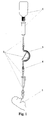
- Figure 1 shows a raised liquid tank 1 from which a flexible conduit 2 leaves, a segment of which passes through a peristaltic pump 3 which sends a controlled flow of liquid to patient 5 and another segment passes in the safety device according to the invention 4 located between pump 3 and patient 5.
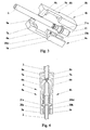
- the safety device 4 shown in the figures 3 and 4 comprises two substantially symmetrical halves 4a, 4b, which each have a parallelepipedic body 5a, 5b. These bodies 5a, 5b are assembled as illustrated by the Figure 4 and fixed to each other by appropriate means such as by welding, clipping or screwing for example. Each parallelepiped body 5a, 5b is integral with a elastic arm 6a, 6b carrying at its end a jaw of substantially triangular section 7a, 7b defining a crushing line transverse to flexible conduit 2.
- Each elastic arm still has a bearing surface 8a, 8b intended to deform the section of the flexible conduit 2 so to have a large contact surface between this flexible conduit 2 and the bearing surfaces 8a, 8b, to allow good transmission of duct pressure flexible 2 with elastic arms 6a, 6b.
- Two gripping elements 9a, 9b extend along two lateral edges respective opposites of the bearing surfaces 8a, 8b.
- Each parallelepipedic body 5a, 5b has a semi-cylindrical recess 20a, 20b whose longitudinal profile is substantially complementary to that of a connector 21 intended to join two segments of the flexible conduit 2.
- This connector 21 has an annular flange 21a intended to be housed in a corresponding portion 20a 1 , 20b 1 of the semi-cylindrical recesses 20a, 20b to form an anchorage between the safety device and the flexible conduit 2.
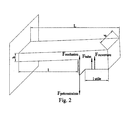
- the dimensions of the elastic arms 6a, 6b can be calculated from the following equations. The main forces and other parameters important for this calculation are shown in Figure 2.
- ⁇ M ext 0 in which F preload : initial tension force generated by bending the arm
- F occlusion force necessary to ensure occlusion
- F tube force due to the slight tightening applied to the tube
- F opening force due to the pressure applied to the flat surface
- L total length of the moving part 1: flexible arm length l useful : length of the surface allowing the opening
- the gripping elements 9a, 9b allow, if necessary, to manually separate the jaws 7a, 7b from way to open the safety device momentarily and reversibly, for example to expel air during priming of the liquid administration line (priming).
- the device 10 according to the second embodiment shown in Figures 5 and 6 has a hollow body elongated 17 of rectangular U-shaped section, intended to receive the flexible conduit 2.
- This elongated hollow body 17 ends at one end with two elastic arms 11a, 11b which have a pair of jaws 12a, 12b, of section substantially triangular, each defining a line of transverse crushing to the flexible duct 2.
- a pair of bearing surfaces 13a, 13b extend beyond the jaws 12a, 12b. These bearing surfaces 13a, 13b are intended to slightly deform the section of flexible conduit 2 so to have a large contact surface between this flexible conduit 2 and these bearing surfaces 13a, 13b, for allow good transmission of duct pressure flexible 2 with elastic arms 11a, 11b.
- a slide 16 comprising a gripping projection 16a is slidably mounted on the elongated body 17 and closes the opening of its U-shaped section.
- This slide 16 carries a substantially triangular finger 15 capable of being inserted between the jaws 12a, 12b during the movement of the slide 16 in the direction of the jaws 12a, 12b so to spread them manually.
- This device can be used either to adjust with precision the flow of the liquid using the slide 16 and of the triangular finger 15, analogously to the pliers roller clamps used conventionally, either to stop the free flow depending on the pressure exerted by the flexible conduit 2 via bearing surfaces 13a, 13b.
- This result could also be obtained for example by conforming the side faces of the triangular finger 15 so as to induce a slight torsion when it acts on the elastic arms 11a, 11b.
- the device safety according to the invention could comprise a single arm elastic 6a or 6b, 11a or 11b.
- the elastic arms can be either manually deformable beyond the elastic limit, either breakable manually to remove the function device security, in case you want to use the tubing with which the safety device is associated with gravity flow and not by a pump.
- the safety device described in both forms of execution is shown to work in one direction flow in conduit 2.
- the surface of these second bearing surfaces could be different, so that conduit 2 opens at different pressures depending on the direction of the flow in this conduit 2.
Abstract
Description
La présente invention concerne un nouveau dispositif de sécurité pour arrêter l'écoulement libre d'un liquide dans un conduit souple.The present invention relates to a new device device to stop the free flow of a liquid in a flexible duct.
Il est connu d'administrer à des patients des liquides ou fluides, notamment des solutions salines, de formulations aqueuses nutritives ou médicamenteuses par voie entérale (c'est-à-dire par l'intermédiaire du système digestif, par exemple par injection dans l'estomac) ou par voie parentérale (évitant le système digestif, par exemple par injection i.v.). Ces liquides sont en général fournis aux patients à partir d'un réservoir surélevé par rapport au patient par l'intermédiaire d'un conduit souple, le débit étant régulé soit uniquement au moyen d'une pince à galet (roller clamp) lorsque l'écoulement se fait par gravité, soit au moyen d'une pompe d'infusion, souvent une pompe péristaltique, qui dose l'injection au cours du temps.It is known to administer fluids to patients or fluids, including saline solutions, nutritious or medicinal aqueous formulations by enteral route (i.e. via the system digestive, for example by injection into the stomach) or by parenteral route (avoiding the digestive system, for example by i.v. injection). These liquids are generally provided to patients from a tank raised above to the patient through a flexible conduit, the flow rate being regulated either only by means of pliers roller clamp when the flow is done by gravity, either by means of an infusion pump, often a peristaltic pump, which doses the injection during time.
Dans le cas de l'utilisation d'une pompe péristaltique il existe un risque lié au positionnement du conduit souple dans la tête de la pompe. Si celui-ci est mal placé ou s'il sort de son logement, le débit n'est plus contrôlé et le liquide peut s'écouler librement par gravité, avec parfois des conséquences très graves pour le patient, par exemple le surdosage d'un médicament ou la suralimentation avec un débordement de l'estomac vers les voies respiratoires. Ce risque existe également lors d'une administration par gravité dans le cas où l'utilisateur oublie de fermer la pince à galet. When using a peristaltic pump there is a risk linked to the positioning of the flexible duct in the pump head. If this one is badly placed or if comes out of its housing, the flow is no longer controlled and the liquid can flow freely by gravity, sometimes with very serious consequences for the patient, for example overdosing on a drug or overeating with a overflow from the stomach to the respiratory tract. This risk also exists during administration by severity in case the user forgets to close the roller clamp.
Pour remédier au risque d'écoulement libre, diverses solutions ont été proposées.To remedy the risk of free flow, various solutions have been proposed.
Le brevet américain No. 6,461,335 ou No. 6,494,864 par exemple décrit une valve placée à l'intérieur du conduit souple agencée pour s'ouvrir automatiquement sous l'effet de la force de traction transmise à la partie du conduit souple en amont de la valve par la pression du liquide lorsque la pompe fonctionne correctement, et se refermer dès que cette pression est inférieure à un certain seuil. Le positionnement de cette valve à l'intérieur du conduit souple n'est pas facile à réaliser dans des conditions stériles.U.S. Patent No. 6,461,335 or No. 6,494,864 by example describes a valve placed inside the duct flexible arranged to open automatically under the effect of the tensile force transmitted to the part of the duct flexible upstream of the valve by liquid pressure when the pump is working properly, and close again as soon as this pressure is below a certain threshold. The positioning of this valve inside the duct flexible is not easy to achieve under conditions sterile.
Le brevet américain No. 4,689,043 propose un dispositif à positionner autour du conduit souple comportant des moyens d'écrasement de celui-ci, qui sont actionnables par une poignée de façon à obturer le conduit lorsque la pompe ne fonctionne pas correctement. Ce dispositif est de structure compliquée et n'est pas automatisé.U.S. Patent No. 4,689,043 provides a device to be positioned around the flexible duct comprising crushing means thereof, which can be actuated by a handle so as to close off the duct when the pump does not work correctly. This device is structured complicated and is not automated.
Le brevet américain No. 5,423,759 décrit un autre dispositif qui comporte des moyens d'écrasement du conduit souple, agencés pour obturer le conduit dès que la pression du liquide est inférieure à une valeur donnée, et un capteur de pression électronique qui mesure cette pression en amont du dispositif, la compare à une valeur de référence et envoie des signaux pour piloter les moyens d'écrasement. Ce dispositif comporte une partie électronique susceptible de dérèglements et coûteuse.U.S. Patent No. 5,423,759 describes another device which includes means for crushing the duct flexible, arranged to seal the duct as soon as the pressure liquid is less than a given value, and a sensor electronic pressure which measures this pressure in upstream of the device, compare it to a reference value and sends signals to control the crushing means. This device includes an electronic part capable of and costly.
Le problème ou but de l'invention est de proposer un dispositif de sécurité contre l'écoulement libre qui ne présente pas les inconvénients sus-mentionnés. The problem or object of the invention is to provide a safety device against free flow which does not not have the above-mentioned drawbacks.
Ce problème est résolu par l'invention telle que définie par le jeu de revendications ci-joint.This problem is solved by the invention such that defined by the attached set of claims.
L'invention concerne un dispositif de sécurité pour arrêter l'écoulement libre d'un liquide dans un conduit souple qui comporte des moyens d'écrasement du conduit souple, caractérisé en ce que ces moyens d'écrasement du conduit souple sont des moyens élastiques calibrés pour ne permettre le passage du liquide que lorsque la pression du liquide dépasse une valeur donnée.The invention relates to a safety device for stop the free flow of a liquid in a conduit flexible which includes means for crushing the duct flexible, characterized in that these means of crushing the flexible conduit are elastic means calibrated so as not to allow the passage of liquid only when the pressure of the liquid exceeds a given value.
Selon le mode d'exécution préféré de l'invention, les moyens élastiques calibrés comprennent une paire de bras élastiques, chacun de ces bras portant une mâchoire d'écrasement et une surface d'appui. Ces bras élastiques sont soumis à une précontrainte initiale de flexion suffisante pour que les mâchoires d'écrasement obturent le conduit souple. Ces surfaces d'appui situées près de l'entrée du dispositif et en contact avec le conduit souple transmettent au bras élastiques une force proportionnelle à la pression du liquide en amont du dispositif. Les mâchoires d'écrasement ne s'ouvrent que lorsque cette force dépasse la précontrainte initiale de flexion des bras. On choisit cette précontrainte de façon à ne permettre cette ouverture que lorsque la pression du liquide dépasse une valeur seuil donnée, comprise entre la pression d'écoulement libre et la pression du liquide lorsque la pompe fonctionne correctement. Ainsi le dispositif arrêtera le liquide en cas d'écoulement libre et le laissera passer lorsque la pompe fonctionne correctement.According to the preferred embodiment of the invention, the calibrated elastic means include a pair of arms elastic, each of these arms carrying a jaw of crushing and a support surface. These elastic arms are subjected to an initial bending preload sufficient for the crushing jaws to block the flexible duct. These bearing surfaces located near the inlet of the device and in contact with the flexible conduit transmit to the elastic arms a force proportional to the pressure of the liquid upstream of the device. The crush jaws only open when this force exceeds the initial bending preload of the arms. We chooses this prestress so as not to allow this opening only when the liquid pressure exceeds a given threshold value, between pressure free flow and liquid pressure when the pump is working properly. So the device will stop the liquid in case of free flow and will let it pass when the pump is working properly.
La précontrainte initiale de flexion des bras dépend de leur géométrie et des propriétés, en particulier du module d'élasticité de la matière qui les constitue. On dispose de formules permettant de calculer les dimensions des bras pour une matière donnée.The initial bending preload of the arms depends of their geometry and properties, in particular the modulus of elasticity of the material which constitutes them. We has formulas for calculating dimensions arms for a given material.
Le dispositif peut être constitué d'une matière plastique telle que le polypropylène, le polyéthylène de haute densité, le polystyrène, le chlorure de polyvinyl, un copolymère styrène-butadiène ou un copolymère acrylonitrile-butadiène-styrène. Il est alors commodément fabriqué par moulage par injection.The device can be made of a material plastic such as polypropylene, polyethylene high density, polystyrene, polyvinyl chloride, a styrene-butadiene copolymer or an acrylonitrile-butadiene-styrene copolymer. It is then conveniently manufactured by injection molding.
Le dispositif peut aussi être constitué d'un métal tel que l'aluminium ou l'acier inoxydable, en particulier l'acier à ressort inoxydable.The device can also be made of a metal such than aluminum or stainless steel, in particular stainless spring steel.
Il peut notamment être fabriqué à partir d'un fil d'acier inoxydable à ressort, ou encore être formé ou plié à partir d'une tôle ou d'une feuille métallique.It can in particular be made from a wire stainless steel with spring, or be formed or folded from a metal sheet or sheet.
De préférence le dispositif de sécurité comporte des éléments de préhension pour agir manuellement sur les mâchoires d'écrasement de façon à permettre temporairement le passage du liquide, par exemple pour permettre l'amorçage de la ligne d'administration.Preferably the security device includes gripping elements for manual action on the jaws of crushing so as to temporarily allow the passage of the liquid, for example to allow priming of the administration line.
Selon un mode d'exécution avantageux le dispositif comporte des moyens pour maítriser de façon précise l'ouverture des mâchoires d'écrasement de façon à réguler le débit du liquide. Ces moyens peuvent comprendre par exemple un doigt entraíné par une coulisse qui s'insère entre les mâchoires d'écrasement. Le même dispositif pourra alors servir soit à réguler le débit de liquide, de façon analogue à une pince à galet (roller clamp), lorsqu'on n'utilise pas de pompe, soit à protéger contre l'écoulement libre lorsqu'on utilise une pompe. According to an advantageous embodiment, the device includes means for precisely controlling the opening crushing jaws so as to regulate the liquid flow. These means may include, for example a finger driven by a slide that fits between the crushing jaws. The same device can then serve either to regulate the flow of liquid, in a similar manner roller clamp, when not in use no pump, either to protect against free flow when using a pump.
Le dispositif de sécurité de l'invention peut être utilisé dans toutes les applications où un risque existe en cas de passage de liquide au dessous d'une valeur donnée de la pression.The security device of the invention can be used in all applications where a risk exists in liquid passing below a given value of pressure.
L'utilisation du dispositif de l'invention présente un intérêt particulier dans le domaine médical en particulier pour l'administration à des patients de solutions salines glucosées, de formulations aqueuses nutritives ou médicamenteuses, de solution saline ou glucosée, ou de solution isotonique par voie entérale ou parentérale.The use of the device of the invention presents a particular interest in the medical field in particular for administering saline solutions to patients glucose, aqueous nutritious or medicinal formulations, saline or glucose solution, or solution isotonic enterally or parenterally.
Son utilisation est également avantageuse dans le domaine vétérinaire, l'agriculture, la chimie, le traitement de l'eau potable etc...Its use is also advantageous in the veterinary, agriculture, chemistry, treatment potable water etc ...
D'autres particularités et avantages de la présente
invention apparaítront dans la description qui va suivre,
qui sera faite à l'aide des desseins annexés qui
illustrent, schématiquement et à titre d'exemple, deux
formes d'exécution du dispositif de sécurité contre
l'écoulement libre de cette invention.
La figure 1 montre un réservoir de liquide 1 surélevé duquel sort un conduit souple 2 dont un segment passe dans une pompe péristaltique 3 qui envoie un débit contrôlé de liquide vers le patient 5 et dont un autre segment passe dans le dispositif de sécurité selon l'invention 4 situé entre la pompe 3 et le patient 5.Figure 1 shows a raised liquid tank 1 from which a flexible conduit 2 leaves, a segment of which passes through a peristaltic pump 3 which sends a controlled flow of liquid to patient 5 and another segment passes in the safety device according to the invention 4 located between pump 3 and patient 5.
Le dispositif de sécurité 4 représenté sur les figures 3 et 4 comprend deux moitiés sensiblement symétriques 4a, 4b, qui comportent chacune un corps parallélépipédique 5a, 5b. Ces corps 5a, 5b sont assemblés comme illustré par la figure 4 et fixés l'un à l'autre par des moyens appropriés tels que par soudage, clipsage ou vissage par exemple. Chaque corps parallélépipédique 5a, 5b est solidaire d'un bras élastique 6a, 6b portant à son extrémité une mâchoire de section sensiblement triangulaire 7a, 7b définissant une ligne d'écrasement transversale au conduit souple 2. Chaque bras élastique présente encore une surface d'appui 8a, 8b destinée à déformer la section du conduit souple 2 de manière à avoir une grande surface de contact entre ce conduit souple 2 et les surfaces d'appui 8a, 8b, pour permettre une bonne transmission de la pression du conduit souple 2 aux bras élastiques 6a, 6b. Deux éléments de préhension 9a, 9b s'étendent le long de deux bords latéraux opposés respectifs des surfaces d'appui 8a, 8b.The safety device 4 shown in the figures 3 and 4 comprises two substantially symmetrical halves 4a, 4b, which each have a parallelepipedic body 5a, 5b. These bodies 5a, 5b are assembled as illustrated by the Figure 4 and fixed to each other by appropriate means such as by welding, clipping or screwing for example. Each parallelepiped body 5a, 5b is integral with a elastic arm 6a, 6b carrying at its end a jaw of substantially triangular section 7a, 7b defining a crushing line transverse to flexible conduit 2. Each elastic arm still has a bearing surface 8a, 8b intended to deform the section of the flexible conduit 2 so to have a large contact surface between this flexible conduit 2 and the bearing surfaces 8a, 8b, to allow good transmission of duct pressure flexible 2 with elastic arms 6a, 6b. Two gripping elements 9a, 9b extend along two lateral edges respective opposites of the bearing surfaces 8a, 8b.
Chaque corps parallélépipédique 5a, 5b comporte un évidement semi-cylindrique 20a, 20b dont le profil longitudinal est sensiblement complémentaire de celui d'un raccord 21 destiné à réunir deux segments du conduit souple 2. Ce raccord 21 présente une collerette annulaire 21a destinée à être logée dans une portion correspondante 20a1, 20b1 des évidements semi-cylindriques 20a, 20b pour former un ancrage entre le dispositif de sécurité et le conduit souple 2.Each parallelepipedic body 5a, 5b has a semi-cylindrical recess 20a, 20b whose longitudinal profile is substantially complementary to that of a connector 21 intended to join two segments of the flexible conduit 2. This connector 21 has an annular flange 21a intended to be housed in a corresponding portion 20a 1 , 20b 1 of the semi-cylindrical recesses 20a, 20b to form an anchorage between the safety device and the flexible conduit 2.
Comme illustré par la figure 4, lorsque le dispositif est monté et traversé par le conduit souple 2 et que les deux mâchoires 7a, 7b écrasent ce conduit souple 2, les deux bras flexibles 6a, 6b sont soumis à une précontrainte initiale de flexion, suffisante pour obturer le conduit souple 2 lorsque la pression du liquide dans ce conduit souple en amont des mâchoires 7a, 7b (en haut sur la figure 4) ne dépasse pas une valeur seuil correspondant à la pression de l'écoulement libre du liquide dans ce conduit souple 2.As illustrated in Figure 4, when the device is mounted and traversed by the flexible conduit 2 and that the two jaws 7a, 7b crush this flexible conduit 2, the two flexible arms 6a, 6b are preloaded initial bending, sufficient to seal the duct flexible 2 when the pressure of the liquid in this conduit flexible upstream of the jaws 7a, 7b (top in the figure 4) does not exceed a threshold value corresponding to the pressure of the free flow of liquid in this conduit flexible 2.
Lorsque la pompe fonctionne correctement, la pression en amont du dispositif de sécurité est transmise aux bras élastiques 6a, 6b, par l'intermédiaire du conduit souple 2 en contact avec les surfaces d'appui 8a, 8b. Cette pression doit développer une force suffisante pour écarter les mâchoires 7a, 7b et ouvrir le conduit souple afin de laisser passer le liquide.When the pump is working properly, the pressure upstream of the safety device is transmitted to the arms elastic 6a, 6b, via flexible conduit 2 in contact with the bearing surfaces 8a, 8b. This pressure must develop sufficient force to spread the jaws 7a, 7b and open the flexible conduit to let the liquid pass.
Les dimensions des bras élastiques 6a, 6b peuvent être
calculées à partir des équations suivantes. Les principales
forces et autres paramètres importants pour ce calcul sont
représentés sur la Figure 2.

Fprécontrainte : force de tension initiale générée par la
flexion du bras
Focclusion : force nécessaire pour assurer l'occlusion
Ftube : force due au léger serrage appliqué sur le tube
Fouverture : force due à la pression appliquée sur la
surface plane
L : longueur totale de la partie mobile
1 : longueur du bras flexible
lutile : longueur de la surface qui permet l'ouvertureThe dimensions of the elastic arms 6a, 6b can be calculated from the following equations. The main forces and other parameters important for this calculation are shown in Figure 2.
F preload : initial tension force generated by bending the arm
F occlusion : force necessary to ensure occlusion
F tube : force due to the slight tightening applied to the tube
F opening : force due to the pressure applied to the flat surface
L: total length of the moving part
1: flexible arm length
l useful : length of the surface allowing the opening
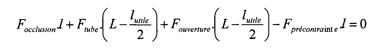
Les dimensions du bras flexible sont calculées à
l'aide de l'équation suivante :
E est le module d'élasticité et f est la flexion
(déplacement vers le haut le long de l'axe FPR-FOC).The dimensions of the flexible arm are calculated using the following equation:
E is the modulus of elasticity and f is the flexion (displacement upwards along the axis F PR -F OC ).
Les éléments de préhension 9a, 9b permettent, si nécessaire, d'écarter manuellement les mâchoires 7a,7b de façon à ouvrir le dispositif de sécurité momentanément et de manière réversible, par exemple pour chasser l'air lors de l'amorçage de la ligne d'administration du liquide (priming).The gripping elements 9a, 9b allow, if necessary, to manually separate the jaws 7a, 7b from way to open the safety device momentarily and reversibly, for example to expel air during priming of the liquid administration line (priming).
Le dispositif 10 selon la seconde forme d'exécution représentée par les figures 5 et 6 comporte un corps creux allongé 17 de section rectangulaire en forme de U, destiné à recevoir le conduit souple 2. Ce corps creux allongé 17 se termine à une extrémité par deux bras élastique 11a, 11b qui présentent une paire de mâchoires 12a, 12b, de section sensiblement triangulaire, définissant chacune une ligne d'écrasement transversale au conduit souple 2. Une paire de surfaces d'appui 13a, 13b s'étendent au-delà des mâchoires 12a, 12b. Ces surfaces d'appui 13a, 13b sont destinée à déformer légèrement la section du conduit souple 2 de manière à avoir une grande surface de contact entre ce conduit souple 2 et ces surfaces d'appui 13a, 13b, pour permettre une bonne transmission de la pression du conduit souple 2 aux bras élastiques 11a, 11b.The device 10 according to the second embodiment shown in Figures 5 and 6 has a hollow body elongated 17 of rectangular U-shaped section, intended to receive the flexible conduit 2. This elongated hollow body 17 ends at one end with two elastic arms 11a, 11b which have a pair of jaws 12a, 12b, of section substantially triangular, each defining a line of transverse crushing to the flexible duct 2. A pair of bearing surfaces 13a, 13b extend beyond the jaws 12a, 12b. These bearing surfaces 13a, 13b are intended to slightly deform the section of flexible conduit 2 so to have a large contact surface between this flexible conduit 2 and these bearing surfaces 13a, 13b, for allow good transmission of duct pressure flexible 2 with elastic arms 11a, 11b.
Une coulisse 16 comportant une saillie de préhension 16a est montée coulissante sur le corps allongé 17 et ferme l'ouverture de sa section en U. Cette coulisse 16 porte un doigt sensiblement triangulaire 15 susceptible de s'insérer entre les mâchoires 12a, 12b lors du déplacement de la coulisse 16 en direction des mâchoires 12a, 12b de manière à les écarter manuellement.A slide 16 comprising a gripping projection 16a is slidably mounted on the elongated body 17 and closes the opening of its U-shaped section. This slide 16 carries a substantially triangular finger 15 capable of being inserted between the jaws 12a, 12b during the movement of the slide 16 in the direction of the jaws 12a, 12b so to spread them manually.
Ce dispositif peut s'utiliser soit pour régler avec précision le débit du liquide à l'aide de la coulisse 16 et du doigt triangulaire 15, de façon analogue aux pinces à roulette (roller clamps) utilisées de façon conventionnelle, soit pour arrêter l'écoulement libre en fonction de la pression exercée par le conduit souple 2 par l'intermédiaire des surfaces d'appui 13a, 13b.This device can be used either to adjust with precision the flow of the liquid using the slide 16 and of the triangular finger 15, analogously to the pliers roller clamps used conventionally, either to stop the free flow depending on the pressure exerted by the flexible conduit 2 via bearing surfaces 13a, 13b.
Dans une variante, on pourrait soit conformer les mâchoires 12a, 12b de manière à ce qu'elles forment entre elles un très léger angle de quelques degrés, de préférence 2° ou 3°, qui permette la fermeture du conduit 2, mais permet de l'ouvrir plus à une extrémité de la section qu'à l'autre extrémité de cette même section. Ceci permet d'assurer un très faible écoulement. Ce résultat pourrait aussi être obtenu par exemple en conformant les faces latérales du doigt triangulaire 15 de manière à induire une légère torsion lorsqu'il agit sur les bras élastiques 11a, 11b.Alternatively, one could either conform the jaws 12a, 12b so that they form between they a very slight angle of a few degrees, preferably 2 ° or 3 °, which allows the closing of the duct 2, but allows it to be opened more at one end of the section than at the other end of this same section. This ensures very low flow. This result could also be obtained for example by conforming the side faces of the triangular finger 15 so as to induce a slight torsion when it acts on the elastic arms 11a, 11b.
Dans le cas d'une utilisation de cette seconde forme d'exécution en tant que dispositif de sécurité pour prévenir l'écoulement intempestif du liquide, le doigt 15 n'est pas inséré entre les mâchoires 12a, 12b et le dispositif fonctionne de façon très semblable au dispositif 4 selon la première forme d'exécution.In the case of use of this second form as a safety device to prevent inadvertent flow of liquid, finger 15 is not inserted between the jaws 12a, 12b and the device works very similar to device 4 according to the first embodiment.
Dans une variante non représentée le dispositif de sécurité selon l'invention pourrait comporter un seul bras élastique 6a ou 6b, 11a ou 11b.In a variant not shown the device safety according to the invention could comprise a single arm elastic 6a or 6b, 11a or 11b.
En variante de la première forme d'exécution illustrée par les figures 3 et 4, les bras élastiques peuvent être soit déformables manuellement au-delà de la limite élastique, soit cassables manuellement pour supprimer la fonction de sécurité du dispositif, au cas où on voudrait utiliser la tubulure à laquelle le dispositif de sécurité est associé avec un écoulement par gravité et non par une pompe.As a variant of the first illustrated embodiment by Figures 3 and 4, the elastic arms can be either manually deformable beyond the elastic limit, either breakable manually to remove the function device security, in case you want to use the tubing with which the safety device is associated with gravity flow and not by a pump.
Le dispositif de sécurité décrit dans les deux formes d'exécution est représenté pour fonctionner dans un sens d'écoulement dans le conduit 2. On pourrait aussi imaginer une variante où il fonctionnerait dans les deux sens en disposant une seconde paire de surfaces d'appui 8a, 8b, 13a, 13b de l'autre côté des mâchoires 7a, 7b, respectivement 12a, 12b. La surface de ces secondes surfaces d'appui pourrait être différente, de manière à ce que le conduit 2 s'ouvre à des pressions différentes suivant le sens de l'écoulement dans ce conduit 2.The safety device described in both forms of execution is shown to work in one direction flow in conduit 2. One could also imagine a variant where it would work both ways in having a second pair of bearing surfaces 8a, 8b, 13a, 13b on the other side of the jaws 7a, 7b, respectively 12a, 12b. The surface of these second bearing surfaces could be different, so that conduit 2 opens at different pressures depending on the direction of the flow in this conduit 2.
Claims (11)
Priority Applications (1)
| Application Number | Priority Date | Filing Date | Title |
|---|---|---|---|
| EP03405252A EP1466646A1 (en) | 2003-04-10 | 2003-04-10 | Security device against free flow |
Applications Claiming Priority (1)
| Application Number | Priority Date | Filing Date | Title |
|---|---|---|---|
| EP03405252A EP1466646A1 (en) | 2003-04-10 | 2003-04-10 | Security device against free flow |
Publications (1)
| Publication Number | Publication Date |
|---|---|
| EP1466646A1 true EP1466646A1 (en) | 2004-10-13 |
Family
ID=32865105
Family Applications (1)
| Application Number | Title | Priority Date | Filing Date |
|---|---|---|---|
| EP03405252A Withdrawn EP1466646A1 (en) | 2003-04-10 | 2003-04-10 | Security device against free flow |
Country Status (1)
| Country | Link |
|---|---|
| EP (1) | EP1466646A1 (en) |
Cited By (6)
| Publication number | Priority date | Publication date | Assignee | Title |
|---|---|---|---|---|
| EP2008681A1 (en) | 2007-06-29 | 2008-12-31 | F.Hoffmann-La Roche Ag | Device for preventing free flow in a catheter |
| EP2218476A1 (en) * | 2009-02-11 | 2010-08-18 | F. Hoffmann-La Roche AG | Leaf spring valve and cone membrane valve |
| US8377001B2 (en) | 2010-10-01 | 2013-02-19 | Abbott Laboratories | Feeding set for a peristaltic pump system |
| US8377000B2 (en) | 2010-10-01 | 2013-02-19 | Abbott Laboratories | Enteral feeding apparatus having a feeding set |
| US8689439B2 (en) | 2010-08-06 | 2014-04-08 | Abbott Laboratories | Method for forming a tube for use with a pump delivery system |
| WO2019048255A1 (en) * | 2017-09-11 | 2019-03-14 | Fresenius Vial Sas | Pinch clamp device |
Citations (4)
| Publication number | Priority date | Publication date | Assignee | Title |
|---|---|---|---|---|
| EP0423978A2 (en) * | 1989-10-20 | 1991-04-24 | Minnesota Mining And Manufacturing Company | Free flow prevention system for infusion pump |
| US5154704A (en) * | 1990-10-31 | 1992-10-13 | Kent Archibald G | IV clamp with tube clip |
| US6142979A (en) * | 1995-03-27 | 2000-11-07 | Zevex | Pinch clip occluder system for infusion sets |
| US6454742B1 (en) * | 2000-03-01 | 2002-09-24 | Sherwood Services, Ag | Valve cuff for a fluid administration system |
-
2003
- 2003-04-10 EP EP03405252A patent/EP1466646A1/en not_active Withdrawn
Patent Citations (4)
| Publication number | Priority date | Publication date | Assignee | Title |
|---|---|---|---|---|
| EP0423978A2 (en) * | 1989-10-20 | 1991-04-24 | Minnesota Mining And Manufacturing Company | Free flow prevention system for infusion pump |
| US5154704A (en) * | 1990-10-31 | 1992-10-13 | Kent Archibald G | IV clamp with tube clip |
| US6142979A (en) * | 1995-03-27 | 2000-11-07 | Zevex | Pinch clip occluder system for infusion sets |
| US6454742B1 (en) * | 2000-03-01 | 2002-09-24 | Sherwood Services, Ag | Valve cuff for a fluid administration system |
Cited By (13)
| Publication number | Priority date | Publication date | Assignee | Title |
|---|---|---|---|---|
| US8382720B2 (en) | 2007-06-29 | 2013-02-26 | Roche Diagnostics International Ag | Device for preventing a free catheter flow |
| WO2009003560A1 (en) * | 2007-06-29 | 2009-01-08 | F.Hoffmann-La Roche Ag | Device for preventing a free catheter flow |
| US8114056B2 (en) | 2007-06-29 | 2012-02-14 | Roche Diagnostics International Ag | Device for preventing a free catheter flow |
| EP2008681A1 (en) | 2007-06-29 | 2008-12-31 | F.Hoffmann-La Roche Ag | Device for preventing free flow in a catheter |
| EP2218476A1 (en) * | 2009-02-11 | 2010-08-18 | F. Hoffmann-La Roche AG | Leaf spring valve and cone membrane valve |
| US8251959B2 (en) | 2009-02-11 | 2012-08-28 | Roche Diagnostics International Ag | Leaf spring valve and cone membrane valve |
| US8689439B2 (en) | 2010-08-06 | 2014-04-08 | Abbott Laboratories | Method for forming a tube for use with a pump delivery system |
| US8377000B2 (en) | 2010-10-01 | 2013-02-19 | Abbott Laboratories | Enteral feeding apparatus having a feeding set |
| US8377001B2 (en) | 2010-10-01 | 2013-02-19 | Abbott Laboratories | Feeding set for a peristaltic pump system |
| WO2019048255A1 (en) * | 2017-09-11 | 2019-03-14 | Fresenius Vial Sas | Pinch clamp device |
| CN111093752A (en) * | 2017-09-11 | 2020-05-01 | 费森尤斯维尔公司 | Throttle clamp |
| US11629790B2 (en) | 2017-09-11 | 2023-04-18 | Fresenius Vial Sas | Pinch clamp device |
| CN111093752B (en) * | 2017-09-11 | 2023-11-21 | 费森尤斯维尔公司 | Throttle clamp |
Similar Documents
| Publication | Publication Date | Title |
|---|---|---|
| EP0927306B1 (en) | Portable peristaltic pump | |
| EP0927307B1 (en) | Miniature peristaltic pump | |
| EP2648635B1 (en) | Device for tensioning a flexible band | |
| FR2492261A1 (en) | CONNECTION FOR THE ESTABLISHMENT OF CONNECTIONS IN PIPING SYSTEMS USED IN MEDICINE | |
| FR2561924A1 (en) | FLOW CONTROL DEVICE | |
| FR2609141A1 (en) | STOP VALVE ACTUATED BY A CANE GUE | |
| FR2611162A1 (en) | GUIDE BLADE TUBE CUTTER FOR CYLINDRICAL OR NON-PLASTIC PIPE TUBES | |
| EP0546966A1 (en) | Sampling and infusion connection | |
| EP1466646A1 (en) | Security device against free flow | |
| CA2872742A1 (en) | Linear peristaltic pump | |
| CN107206224A (en) | The transfusion pump cassette of the online current limiter bypassed with finger | |
| EP0532391B1 (en) | Pliers for compressing a pipe, such as a gas duct | |
| FR2902977A1 (en) | SAFETY SUCKET HOLDER | |
| EP2387435B1 (en) | Pinching closed a collapsible tube for biopharmaceutical use | |
| EP0932423B1 (en) | Miniature peristaltic pump for medical use | |
| FR2978919A1 (en) | MULTIVOIE PILOT BOX | |
| EP1023914B1 (en) | Clamping device to compress a flexible tube | |
| FR3093928A1 (en) | Clamp to reshape a flexible tube forming part of a medical device | |
| WO2016174632A1 (en) | Device for protecting and holding in position a probe that is intended to be placed inside the body of a patient in communication with the outside | |
| WO2023031067A1 (en) | Device for guiding a syringe | |
| FR2590642A1 (en) | REMOVABLE DISPENSER VALVE FOR LIQUID CONTAINERS | |
| WO2011121513A1 (en) | Oral accessibility device | |
| EP0718005B1 (en) | Infusion device | |
| BE827002A (en) | ROLLER CLAMP FOR A FLOW CONTROL | |
| FR2788985A1 (en) | Automatic safety device for pre-filled syringe comprises cylinder, sprung vanes and reinforced clip, all in one piece |
Legal Events
| Date | Code | Title | Description |
|---|---|---|---|
| PUAI | Public reference made under article 153(3) epc to a published international application that has entered the european phase |
Free format text: ORIGINAL CODE: 0009012 |
|
| AK | Designated contracting states |
Kind code of ref document: A1 Designated state(s): AT BE BG CH CY CZ DE DK EE ES FI FR GB GR HU IE IT LI LU MC NL PT RO SE SI SK TR |
|
| AX | Request for extension of the european patent |
Extension state: AL LT LV MK |
|
| AKX | Designation fees paid | ||
| REG | Reference to a national code |
Ref country code: DE Ref legal event code: 8566 |
|
| STAA | Information on the status of an ep patent application or granted ep patent |
Free format text: STATUS: THE APPLICATION IS DEEMED TO BE WITHDRAWN |
|
| 18D | Application deemed to be withdrawn |
Effective date: 20050414 |