BACKGROUND OF THE INVENTION
-
The present invention relates to the
integration of business applications in an integrated
business solutions computing environment. More
specifically, the present invention relates to a
dynamic user interface for integrating such business
applications.
-
Businesses have typically used a variety of
mechanisms to control and analyze business operations
such as accounting, payroll, human resources,
employee tracking, customer relations tracking, etc.
Tools which provide these functions are often
implemented using computer software. For example, a
software package may manage business accounting,
another software package might be responsible for
receiving new orders, yet another software package
will track warehouse inventory and still another
package may handle order fulfillment and shipment. In
another example, a business software package operated
by one business will need to exchange data with a
software package operated by another business to
allow a business-to-business transaction to occur.
-
When business tools are implemented in
software, it is not unusual for proprietary software
packages to be responsible for each individual
business task. However, this implementation is
cumbersome and requires the same data to be entered
in differing formats among the various business
applications. In order to improve efficiency,
integration applications have been developed which
are used to integrate various elements of one
business application with elements of another
business application.
-
For example, if a software package which is
used to obtain new orders includes objects (or
"entities") having data fields of the form
CustomerNameLast and CustomerNameFirst, it is
straightforward to map those entries to accounting
software having entities the data fields
BillingAddressFirst and BillingAddressLast. In such
an integration system, the relationship between
entities in one system (i.e., computer system or
application) and entities in another system can be
stored in tables. A system administrator can
configure entity mapping between the systems by
selecting between the various entities of the two
systems.
-
In order to facilitate the entity mapping
configuration performed by the system administrator,
user interfaces are used which present the entity
tables in a user friendly format. However, such a
user interface is typically a custom solution which
must be specifically coded for each integration
application.
SUMMARY OF THE INVENTION
-
A method of providing a dynamic user
interface for mapping entities between a plurality of
business applications in an integrated business
solutions computing environment is provided. A first
system specific assembly and first user interface
configuration data is retrieved for a first entity.
A second system specific assembly is retrieved for a
second entity of a second application. A dynamic user
interface is generated based upon the first system
specific assembly, first user interface configuration
data and second system specific assembly. A dynamic
user interface and system for generating such an
interface are also provided.
BRIEF DESCRIPTION OF THE DRAWINGS
-
- FIG. 1 is one exemplary embodiment of an
environment in which the present invention can be
used.
- FIG. 2 is a schematic diagram which
illustrates operation of the user interface generator
of the present invention.
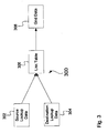
- FIG. 3 is a block diagram showing the
joining of source lookup data, destination lookup
data and a link table into grid data.
- FIG. 4 is a schematic diagram showing an
example data store of the present invention.
- FIG. 5 is a screen shot which illustrates a
user interface for configuring an entity of a
business application.
- FIG. 6 is a screen shot showing a user
interface for mapping entities.
- FIG. 7 is a screen shot showing a user
interface for configuring the mapping shown in FIG.
6.
- FIG. 8 is a screen shot showing a user
interface for controlling the publication of
entities.
-
DETAILED DESCRIPTION OF THE PREFERRED EMBODIMENTS
-
FIG. 1 illustrates an example of a suitable
computing system environment 100 on which the
invention may be implemented. The computing system
environment 100 is only one example of a suitable
computing environment and is not intended to suggest
any limitation as to the scope of use or
functionality of the invention. Neither should the
computing environment 100 be interpreted as having
any dependency or requirement relating to any one or
combination of components illustrated in the
exemplary operating environment 100.
-
The invention is operational with numerous
other general purpose or special purpose computing
system environments or configurations. Examples of
well-known computing systems, environments, and/or
configurations that may be suitable for use with the
invention include, but are not limited to, personal
computers, server computers, hand-held or laptop
devices, multiprocessor systems, microprocessor-based
systems, set top boxes, programmable consumer
electronics, network PCs, minicomputers, mainframe
computers, telephony systems, distributed computing
environments that include any of the above systems or
devices, and the like.
-
The invention may be described in the
general context of computer-executable instructions,
such as program modules, being executed by a
computer. Generally, program modules include
routines, programs, objects, components, data
structures, etc. that perform particular tasks or
implement particular abstract data types. The
invention may also be practiced in distributed
computing environments where tasks are performed by
remote processing devices that are linked through a
communications network. In a distributed computing
environment, program modules may be located in both
local and remote computer storage media including
memory storage devices.
-
With reference to FIG. 1, an exemplary
system for implementing the invention includes a
general-purpose computing device in the form of a
computer 110. Components of computer 110 may
include, but are not limited to, a processing unit
120, a system memory 130, and a system bus 121 that
couples various system components including the
system memory to the processing unit 120. The system
bus 121 may be any of several types of bus structures
including a memory bus or memory controller, a
peripheral bus, and a local bus using any of a
variety of bus architectures. By way of example, and
not limitation, such architectures include Industry
Standard Architecture (ISA) bus, Micro Channel
Architecture (MCA) bus, Enhanced ISA (EISA) bus,
Video Electronics Standards Association (VESA) local
bus, and Peripheral Component Interconnect (PCI) bus
also known as Mezzanine bus.
-
Computer 110 typically includes a variety
of computer readable media. Computer readable media
can be any available media that can be accessed by
computer 110 and includes both volatile and
nonvolatile media, removable and non-removable media.
By way of example, and not limitation, computer
readable media may comprise computer storage media
and communication media. Computer storage media
includes both volatile and nonvolatile, removable and
non-removable media implemented in any method or
technology for storage of information such as
computer readable instructions, data structures,
program modules or other data. Computer storage
media includes, but is not limited to, RAM, ROM,
EEPROM, flash memory or other memory technology, CD-ROM,
digital versatile disks (DVD) or other optical
disk storage, magnetic cassettes, magnetic tape,
magnetic disk storage or other magnetic storage
devices, or any other medium which can be used to
store the desired information and which can be
accessed by computer 110. Communication media
typically embodies computer readable instructions,
data structures, program modules or other data in a
modulated data signal such as a carrier wave or other
transport mechanism and includes any information
delivery media. The term "modulated data signal"
means a signal that has one or more of its
characteristics set or changed in such a manner as to
encode information in the signal. By way of example,
and not limitation, communication media includes
wired media such as a wired network or direct-wired
connection, and wireless media such as acoustic, RF,
infrared and other wireless media. Combinations of
any of the above should also be included within the
scope of computer readable media.
-
The system memory 130 includes computer
storage media in the form of volatile and/or
nonvolatile memory such as read only memory (ROM) 131
and random access memory (RAM) 132. A basic
input/output system 133 (BIOS), containing the basic
routines that help to transfer information between
elements within computer 110, such as during start-up,
is typically stored in ROM 131. RAM 132
typically contains data and/or program modules that
are immediately accessible to and/or presently being
operated on by processing unit 120. By way of
example, and not limitation, FIG. 1 illustrates
operating system 134, application programs 135, other
program modules 136, and program data 137.
-
The computer 110 may also include other
removable/non-removable volatile/nonvolatile computer
storage media. By way of example only, FIG. 1
illustrates a hard disk drive 141 that reads from or
writes to non-removable, nonvolatile magnetic media,
a magnetic disk drive 151 that reads from or writes
to a removable, nonvolatile magnetic disk 152, and an
optical disk drive 155 that reads from or writes to a
removable, nonvolatile optical disk 156 such as a CD
ROM or other optical media. Other removable/non-removable,
volatile/nonvolatile computer storage
media that can be used in the exemplary operating
environment include, but are not limited to, magnetic
tape cassettes, flash memory cards, digital versatile
disks, digital video tape, solid state RAM, solid
state ROM, and the like. The hard disk drive 141 is
typically connected to the system bus 121 through a
non-removable memory interface such as interface 140,
and magnetic disk drive 151 and optical disk drive
155 are typically connected to the system bus 121 by
a removable memory interface, such as interface 150.
-
The drives and their associated computer
storage media discussed above and illustrated in FIG.
1, provide storage of computer readable instructions,
data structures, program modules and other data for
the computer 110. In FIG. 1, for example, hard disk
drive 141 is illustrated as storing operating system
144, application programs 145, other program modules
146, and program data 147. Note that these
components can either be the same as or different
from operating system 134, application programs 135,
other program modules 136, and program data 137.
Operating system 144, application programs 145, other
program modules 146, and program data 147 are given
different numbers here to illustrate that, at a
minimum, they are different copies.
-
A user may enter commands and information
into the computer 110 through input devices such as a
keyboard 162, a microphone 163, and a pointing device
161, such as a mouse, trackball or touch pad. Other
input devices (not shown) may include a joystick,
game pad, satellite dish, scanner, or the like. For
natural user interface applications, a user may
further communicate with the computer using speech,
handwriting, gaze (eye movement), and other gestures.
To facilitate a natural user interface, a computer
may include microphones, writing pads, cameras,
motion sensors, and other devices for capturing user
gestures. These and other input devices are often
connected to the processing unit 120 through a user
input interface 160 that is coupled to the system
bus, but may be connected by other interface and bus
structures, such as a parallel port, game port or a
universal serial bus (USB). A monitor 191 or other
type of display device is also connected to the
system bus 121 via an interface, such as a video
interface 190. In addition to the monitor, computers
may also include other peripheral output devices such
as speakers 197 and printer 196, which may be
connected through an output peripheral interface 190.
-
The computer 110 may operate in a networked
environment using logical connections to one or more
remote computers, such as a remote computer 180. The
remote computer 180 may be a personal computer, a
hand-held device, a server, a router, a network PC, a
peer device or other common network node, and
typically includes many or all of the elements
described above relative to the computer 110. The
logical connections depicted in FIG. 1 include a
local area network (LAN) 171 and a wide area network
(WAN) 173, but may also include other networks. Such
networking environments are commonplace in offices,
enterprise-wide computer networks, intranets and the
Internet.
-
When used in a LAN networking environment,
the computer 110 is connected to the LAN 171 through
a network interface or adapter 170. When used in a
WAN networking environment, the computer 110
typically includes a modem 172 or other means for
establishing communications over the WAN 173, such as
the Internet. The modem 172, which may be internal
or external, may be connected to the system bus 121
via the user input interface 160, or other
appropriate mechanism. In a networked environment,
program modules depicted relative to the computer
110, or portions thereof, may be stored in the remote
memory storage device. By way of example, and not
limitation, FIG. 1 illustrates remote application
programs 185 as residing on remote computer 180. It
will be appreciated that the network connections
shown are exemplary and other means of establishing, a
communications link between the computers may be
used.
-
FIG. 2 is a simplified block diagram which
graphically illustrates an integration engine or user
interface generator 200 for generating a user interface
for mapping entities between two business systems in
accordance with the present invention. As used herein,
a "system" can refer to different computer systems such
as single computer system 110 and 180 shown in FIG. 1,
or different business applications such as application
programs 135 running on a single computer system 110.
In the example of FIG. 2, mapping between System 1 and
System 2 is illustrated. System 1 includes two
entities, Entity 1 and Entity 2. Similarly, System 2
includes two entities, Entity 1 and Entity 2. FIG. 2
also illustrates a System Mapping 202 which maps
between System 1 and System 2 and Entity Mappings 204
and 206 which map between each system's Entity 1 and
each system's Entity 2. Further, each System, each
Entity and each Map 202, 204 and 206 includes
Configuration Data which is associated with a system
level, an Entity level, a System mapping level and an.
Entity mapping level. Similarly, each System, Entity
and Map includes User Interface Configuration Data
which can be, for example, an XML text string. The
configuration illustrated in FIG. 2 can be implemented
through known techniques, such as data base tables,
which store and define the relationships between the
Systems, Entities, Maps, Configuration Data and User
Interface Configuration Data.
-
In general, engine 200 relates entities on
one system to entities on another system and provides a
dynamic user interface for controlling this
relationship. For example, if System 1 receives a sales
order from System 2, and Entity 2 relates to inventory
methods, the Configuration Data for Entity 2 can define
how inventory is allocated when a sales order is
received from System 2. The Configuration Data is such
that it can be assigned to a particular System or
Entity, but also assigned based upon how it is mapped
to another System or Entity.
-
FIG. 2 also illustrates an example in which
Entity 2 of System 1 is mapped to a second entity,
Entity 3 of System 2 based upon Map 208. For example,
the shipping method of System 1 can map to a shipping
method associated with an account, a shipping method
associated with a contact, a shipping method associated
with an order and a shipping method associated with an
invoice on System 2. In that case, a single entity in
system 1 is mapped to multiple entities in system 2.
-
The User Interface Configuration Data
(represented by the "UI CONFIG" boxes in FIG. 2)
associated with each node provides the particular user
interface for that System, Entity or Map. For example,
the User Interface Configuration Data for System 1 and
System 2 can be in the form of user selectable tabs
which are defined in a markup language such as XML.
When System 1 is selected, its User Interface
Configuration Data brings up a set of tabs which allow
an administrator to configure Entity 1, Entity 2 or
Maps 202, 204 and 206 for System 1 relative to System
2.
-
The particular user interface can be
selected as desired, for example, textboxes, dropdown
lists, checkboxes, radio buttons, tabs, etc. An example.
of user interface configuration data XML fragment is as
follows:
-
In this string, the <tab> entry refers to a particular
tab on the user interface, for example, a tab which
identifies System 1. The <field> entry provides the
particular user input form described above. The
<lookup> section of the XML string fragment describes
the specific lookup to a system. For example, if the
user interface is to display a list of shipping methods
which are available, the <lookup> section defines this
list. When a particular <field> requires a shipping
method list, it refers to the <lookup> section to
obtain the list.
-
In order for the information set forth in
FIG. 2 to dynamically generate a user interface, the
system and entity names are obtained in a user friendly
format. This can be achieved using a standardized
interface referred to herein as ISystemProxy. This
interface is implemented for each system, such as with
DLLs. For example, if customer A in
System 1 has been
linked to customer B in
System 2, the particular key
values of the two Entities are typically not user
friendly (they could be 32 bit GUIDS, for example).
Similarly, the two Systems may reside on different
physical servers and may not allow their data to be
exposed using normal database connections. The
ISystemProxy has methods that can be invoked to query
the integration engine illustrated in FIG. 2 for a list
of entities that have been linked. Each System is then
queried for a list of entities which are returned as,
for example, XML files. The ISystemProxy can be
implemented in a custom DLL for each particular System
and provides a standardized interface for loading the
tables of the
integration engine 200 with system
specific data. However, the data store of the present
invention can be populated using any appropriate
technique including hard coding the system specific
data during authoring or deployment. For example, the
tables can be populated by submitting an XML string of
the format:
-
The entity name entry is the name of an Entity or table
definition. For example, for every shipping method
contained in a System, an XML string in the format of
String 2 can be provided to the integration engine 200.
The value attribute provides the identification key of
a particular shipping method, for example "1". The
display attribute provides a user friendly
identification of the key, for example "UPS", "Federal
Express", etc.
-
During operation, the integration engine 200
takes source pick list data, for example the XML string
from System 1, and destination pick list data, for
example an XML string from System 2, and places those
lists into a temporary table. Then, the Entity in
System 1 defined in accordance with the String 2 entry
is joined with the appropriate entity or entities in
System 2 based upon the Entity Maps 204, 206, 208.
Using pick lists or other techniques, the
administrator can then map a shipping method from one
System to a shipping method of another System. For
example, a shipping method 1 may correspond to UPS
shipping for System 1 whereas shipping method B can
correspond to UPS shipping for System 2. When the
administrator selects Entity 1 (shipping methods) for
System 1, a popup window or other input field is
provided with a pick list of selectable fields for
the available entities on System 2.
-
FIG. 3 is a block diagram 300 in which
source lookup data stored in table 302 and destination
lookup data stored in table 304 is joined based upon
the relationships defined in a link table 306. The link
table sets forth the mapping illustrated by Entity Maps
204, 206 and 208 in FIG. 2. For example, if the source
and destination lookup data is stored in a SQL
database, this joining can be through a SQL query. The
joined data is stored in table 308 as grid data and can
comprise a plurality of data tables.
-
In some instances the administrator may
change the configuration of an Entity. For example,
assume
Entity 1 for
System 1 is of the following form:
Subsequently, assume the administrator changes
Entity
1 to include a city field such as:
The dynamic user interface of the invention generates
the modified XML string which is returned to
engine
200. The new Entity format can be conveyed to
System
2, or at least an indication provided to
System 2
that the Entity is changed.
-
FIG. 4 is a block diagram of a system
specific data store configuration 400 in one specific
exemplary embodiment. An integration system master
table 402 includes a primary key (PK) associated with
the System ID. The actual system name is associated
with a unique index, U2. Table 402 also contains
other information such as display information,
default configuration and XML configuration.
-
Table 404 provides integration system
entity information including entity type, the source
schema name, the system schema name, publication
information, etc. and includes a foreign key (FK1)
which identifies a particular System ID. An
integration entity configuration table 406 is keyed
to a foreign key (FK1) and provides an entity
identification node name to identify a particular
node in the data store 400 and its configuration
data. Integration entity map table 408 provides the
mapping data used to map between two entities in two
systems. Source and destination entities are
identified with foreign keys. Table 410 provides
specific mapping configuration data for a node in the
data 400. Integration system map table 412 and
integration system map configuration table 414 are
used to map between two systems. They are linked to
an overall integration master table 416. Integration
system configuration table 418 maintains node
configuration data for a system. The actual linking
between entities is provided by integration entity
instance table 420 and integration entity instance
link table 422. Table 420 identifies a particular
entity and table 422 provides the link between
entities. An archive table (not shown) can also be
used to store historical data and track changes to
the entity links.
-
One embodiment of primary steps to generate
and display the dynamic user interface of the
invention are as follows:
Primary Display Steps
-
- 1. Extract XML configuration node from appropriate
system table.
- 2. For each tab group identified in the node: ,
- a. For each section in the tab group:
- i. For each field in the section:
- 1. Determine UI type.
- 2. If lookup data required, call
appropriate system proxy and
retrieve XML lookup data.
- 3. Create appropriate UI widget.
- 4. If UI type is list-type (dropdown,
list table), add each node
from XML lookup data.
- 5. If UI type is linked entity
table, call table generator.
- a. Load linked entity records.
- b. Load source system entity
records.
- c. Load destination system
entity records.
- d. Combine record sets.
- 6. Return Dynamic HTML code from UI
Widget.
- 7. Return code.
- ii. Return section code.
- b. Return tab group code.
- 3. Pass page code to browser.
-
-
In the above steps, an XML configuration node is
extracted from the appropriate system table set forth
in FIG. 4. Based upon the extracted XML configuration
node data, each tab group of the user interface is
identified for the node (as shown in FIGS. 5 and 6).
For each section in the tab group, and for each field
in the section, the particular user interface type is
determined. If lookup data is required, a system
proxy is called which provides XML lookup data for
the particular field, the appropriate user interface
is created. In operation, input field of the dynamic
user interface (pick list, button, etc.) is based
upon the determined user interface type and any
lookup data which was obtained. If the user interface
is a list type (a dropdown list, table, etc.) each
particular node is added from the XML lookup data. On
the otherhand, if the user interface type is a linked
entity table, a table generator routine is called in
which all the linked entity records are loaded, the
source system entities are loaded, and the
destination system entities are loaded (for example
through querying proxies). These record sets are then
joined. Next, dynamic HTML code is generated to link
the appropriate system specific data and the
appropriate user interface. The final page is
assembled and passed to the browser.
-
Once an administrator has entered
configuration data into the user interface defined by
the dynamic XML page, that configuration data must be
submitted to the integration engine such that entries
in the tables set forth in FIG. 4 can be populated.
During such a save operation, the following general
steps are performed:
Save Steps
-
- 1. Receive XML node of data to be saved.
- 2. For each node.
- a. Determine save type.
- i. If integration configuration, or
- ii. If system default data
- 1. Save data value to appropriate
config table and record
- iii. If new entity link, pass data to
platform to create links.
- iv. If system configuration, load system
proxy, and pass data to appropriate
interface method.
-
-
In the save steps set forth above, if a field has
changed, an XML node is received for the new data to
be saved. For each node received, the particular save
type is determined (for example, integration,
configuration or system default data) and the data
value is saved into the appropriate configuration
table shown in FIG. 4. If a new entity link is
created, an XML string is passed to the integration
engine to create the appropriate link by populating
the appropriate link instance in the data store 400
shown in FIG. 4. If the new entry relates to system
configuration, a system proxy is called for the
appropriate system and the data is passed to the
system using the appropriate interface technique.
-
The pick list data can be obtained using
any appropriate technique including hard coding the
data store with system specific data or other input
techniques. However, an automated technique can be
used in which a server proxy is defined for each
system and used to return pick list data for that
system. The server proxy operates in accordance with
a standardized interface. As one example, a retrieve
pick list call can be made to a server proxy of the
form:
RetrievePickList (String ConfigData)
String 5
-
The config data can be, for example, one large XML
string which is comprised of all of the data for a
particular node. The string will contain data for at
least one lookup node. The data can be generated
using the appropriate query technique for a given
system, for example by using a SQL query. In such a
configuration, the string is parsed to identify the
lookup node and then a connection string is retrieved
from the config data. One example connection string
could be of the form, server=server A; database 2.
The RetrievePickList then returns the large XML
string. However, this can be configured as
appropriate for a particular system, for example by
parsing out the server name and passing the entity to
the appropriate server. The XML string is also
updated to include the appropriate entity name used
by the integration engine for a particular entity. In
general, all of the configuration data is passed so
that any desired data can be parsed from the string.
-
The present invention provides a dynamic
user interface for configuring business systems using
an XML string generated from a system specific
assembly. Further, system specific assemblies can be
formed for any system, and the integration engine can
be used across multiple platforms. An interface to
exchange data is implemented on each system in
accordance with an interface specification. The
integration engine can then query the interface and
be used to populate the assembly. This allows the
interface to be designed generically and the system
data that is automatically retrieved is used to
populate the assembly as desired. The XML code is
used as a description of the user interface. This can
be combined with a system interface to interrogate
each system in the integration.
-
FIG. 5 is a screen shot showing an example
user interface in accordance with the present
invention. In FIG. 5, a plurality of tabs are
arranged vertically to allow an administrator to
select a particular system. Within the selected
system, specific tabs are arranged horizontally to
allow the configuration and mapping of entities. In
the example of FIG. 5, Sales Document configuration
is selected which allows the administrator to select
default sales document type identification, how a
credit limit is handled, what order types are to be
published from the system and what invoices are to be
published. The page also allows the administrator to
select how sales documents are to be batched, the
frequency for how sales documents are batched, when
sales documents are batched and how inventory
transactions are handled.
-
FIG. 6 shows a horizontal tab selected
which graphically illustrates the mapping of payment
terms between systems (the "Mapped Entities"). In
FIG. 7, various payment term values from one system
are mapped to or linked to payment term values in
another system. A dropdown list allows a system
administrator to select from other field names. Note
that this table can also be viewed from the
destination system perspective in which the source
fields and destination fields are reversed.
-
FIG. 8 shows one embodiment of the dialog
of the user interface which allows an administrator
to select which entities are published. Note that if
one entity is not published, another entity may also
not be published. For example, if the address entity
is not published, the publishing of the orders entity
is no longer valid and so the orders entity will also
not be published.
-
Although the dynamic user interface of the
present invention can be generated as desired, one
example user interface configuration XML instance for
such a dynamic user interface is as follows:
-
The data set forth in Tables of FIG. 4 can be in
accordance with any desired format. The following are
sample configuration node records for a system-level
configuration:
-
One example pick list schema along with sample data
is as follows:
-
The present invention provides a dynamic
user interface for configuring the relationship
between systems. The system provides for the storage
of an XML layout of the user interface on an
application service provider (ASP) page. The user
interface can comprise a plurality of tabs with
various user interface inputs located under each tab.
Each of the inputs of the user interface input can be
customized as a text box, label, checkbox, dropdown,
table list, etc. Further, each object can be
customized as to the target of its action. For
example data can be targeted at the configuration
data stored as integration meta data, default data
passed to the integrated systems, or the creation of
linked records in the integration itself. The present
invention provides a combination of a markup language
description (such as XML) of the user interface and a
system specific assembly which is used to manage
certain retrieval and configuration methods. The
system specific assembly can be generated using any
appropriate technique including automated techniques
using system proxies. This provides a single
interface to manage integration between multiple
systems.
-
In the present invention, the user
interface generator can be hosted in a web
application. Illustratively, the user interface is
designed to be similar to the user interface used to
configure the systems being integrated. The
integration engine includes a set of tables that
contain a list of the systems that are integrated,
the unique entities within those systems that are
integrated, and the attributes of each of those
entities. Each of these tables has a text field
containing the user interface configuration in an XML
string. Further, each of the tables also has a joined
one-to-many table that contains a list of
configuration nodes that may be used by the
integration itself, or passed on to that entity every
time a document is posted to it. Further, each
integrated system can provide a system specific
assembly that implements a specific interface. This
interface controls retrieving entity schema and
information, retrieving pick list data (for example
as XML), a generic query used to return data (for
example as XML) and a method to control the
publication of data, for example.
-
The XML configuration field for each of the
systems is passed to a main component of the user
interface generator. The generator then proceeds to
read each node and generate the appropriate user
interface control. If the configuration is for a
specific entity-to-entity mapping, an entry can be
made in the XML configuration data that defines the
source system, source entity and destination entity.
The engine will then retrieve the appropriate
configuration from that map, generate the appropriate
user interface information and return the user
interface information inside the main user interface
XML string.
-
When an administrator chooses to save any
changes from the user interface, another component is
passed an XML string from the browser which contains
the nodes that have actually been changed on the
client. The implementation of this function can be
through any appropriate technique such as code
operated on a virtual machine. Upon receiving this
data set, the user interface integration engine loops
through, each node and determines what type of save
operation should be performed. If the save is for
integration specific data, the data is passed to the
integration platform to save in a storage operation.
If the data to be saved is for creating a new link
between entities, then that data is passed to another
components in the integration platform that creates
those links. Finally, if the data to be saved is
system default data, it is stored in the meta data to
be passed to the appropriate document.
-
With the present invention, a system
specific assembly is used by a user interface
generator to generate a dynamic user interface. The
system specific assembly is a set of information
which describes a particular system to be integrated.
New systems can be added to the integration by simply
adding new assemblies for each system. The assembly
can be individually coded or can be automatically
generated using a proxy through a common interface.
The interface illustratively utilizes XML as a
descriptor, however, other techniques can be used
such as XSL (extensible stylesheet language), etc.
-
Although the present invention has been
described with reference to preferred embodiments,
workers skilled in the art will recognize that
changes may be made in form and detail without
departing from the spirit and scope of the invention.