EP1463304A2 - Relay unit for the remote control of a focus lens - Google Patents
Relay unit for the remote control of a focus lens Download PDFInfo
- Publication number
- EP1463304A2 EP1463304A2 EP04251486A EP04251486A EP1463304A2 EP 1463304 A2 EP1463304 A2 EP 1463304A2 EP 04251486 A EP04251486 A EP 04251486A EP 04251486 A EP04251486 A EP 04251486A EP 1463304 A2 EP1463304 A2 EP 1463304A2
- Authority
- EP
- European Patent Office
- Prior art keywords
- control
- focus lens
- switching
- signals
- unit
- Prior art date
- Legal status (The legal status is an assumption and is not a legal conclusion. Google has not performed a legal analysis and makes no representation as to the accuracy of the status listed.)
- Granted
Links
Images


Classifications
-
- H—ELECTRICITY
- H04—ELECTRIC COMMUNICATION TECHNIQUE
- H04N—PICTORIAL COMMUNICATION, e.g. TELEVISION
- H04N23/00—Cameras or camera modules comprising electronic image sensors; Control thereof
- H04N23/60—Control of cameras or camera modules
- H04N23/67—Focus control based on electronic image sensor signals
Definitions
- the present invention relates to relay units and more specifically to relay units for optical devices for use in television cameras, video cameras, television lens, video lens, or the like, which perform automatic focal point detection focus control (hereafter referred to as "AF control").
- AF control automatic focal point detection focus control
- AF control automatic focal point detection control
- the AF control method extracts and evaluates signals corresponding to the sharpness of the subject from picture signals before automatic focal point detection is performed.
- reference numeral 600 denotes a camera with a non-detachable lens unit
- 102 denotes evaluation value generating means for extracting a sharpness evaluation value from the picture signals output from later-described process means 202
- 103 denotes AF driving control means for generating motor control signals such that the sharpness evaluation value generated by the evaluation value generating means 102 is maximized.
- Reference numeral 105 denotes a motor operated under the control of the AF driving control means 103
- 106 denotes a focus lens which is driven along the optical axis by the motor 105.
- Reference numeral 201 denotes a CCD
- 202 denotes process means for converting the output signals of the CCD into a picture format such as NTSC signals or the like
- 203 denotes recording/reproducing means for recording the picture signals, which are the output of the process means 202, on a recording medium, and reproducing the pictures recorded therein.
- the optical flux which has passed through the focus lens 106 is imaged on the imaging face of the CCD 201 for photoelectric conversion by the CCD.
- a held sample is then input to the process means 202, where input signals are converted into a picture format such as NTSC signals or the like, and output to the evaluation value generating means 102 and the recording/reproducing means 203.
- the evaluation value generating means 102 generates sharpness evaluation values for the picture signals output to the evaluation value generating means 102, the sharpness evaluation values relating to the frequency component of the picture being obtained by filter processing or the like and generated in increments of vertical synchronization cycles of the picture signals, and output to the AF driving control means 103.
- motor control signals are generated which move the focus lens 106 to a position wherein the sharpness evaluation value is maximum, sequentially comparing the sharpness evaluation value in increments of vertical synchronization cycles while driving the motor 105, so that the focus lens 106 is moved to the focal point.
- the recording/reproducing means 203 records the output of the process means 202 in the recording medium, and also reproduce the pictures recorded therein.
- the movement direction of the focus lens 106 is determined by moving the focus lens 106 by a small amount. That is, the focal point may either be at the far side of the near side of the current position of the focus lens 106 or the near side of the focus lens.
- the focus lens 106 is moved at a specific speed in order to detect the peak value of the sharpness evaluation value, following the results of determining the direction for driving. This is referred to as "hill-climbing determination".
- the direction of moving the focus lens 106 is reversed, and the focus lens 106 is guided in increments of minute amounts of movement so that the sharpness evaluation value is maximized. This is referred to as "peak determination". Following the peak determination, the sharpness evaluation value is read and compared with the value immediately following the peak determination, and the value has changed, the AF operations are reactivated.
- remote systems are known for monitoring and/or taking pictures of ceremonies or other solemn services or gatherings, etc., by using television cameras, video cameras, television lenses, video lenses, and so forth.
- Such remote systems are not equipped with AF control, and thus require an operator to operate switches and dials to perform functions such as zooming, iris control, focus, and so forth.
- a remote system uses a 12-pin electric interface between the remote control unit and the camera.
- the electric interface has pins assigned to zoom, iris, and focus command signals, control mode signals (switching between speed control and position control), electric power source, ground, and so forth.
- control mode signals switching between speed control and position control
- electric power source ground, and so forth.
- all 12 pins are in use, i.e., there are no more pins available.
- FIG. 7 An example of operations of this remote system is described with reference to Fig. 7.
- the components in Fig. 7 denoted by the reference numerals 105, 106, 201, 202, and 203, in Fig. 6, have already been described above, and accordingly description thereof will be omitted here.
- reference numeral 100 denotes an exchangeable lens unit
- 200 denotes a camera unit
- 400 denotes a remote control unit for supplying to the lens unit 100: command signals for controlling an unshown zoom lens unit, iris unit, and focus lens 106; and switching signals for switching between either speed control or positional control to control the unshown zoom lens unit, iris unit, and focus lens 106.
- Reference numeral 500 denotes a remote control cable connecting the lens unit 100 and the remote control unit 400.
- reference numeral 107 denotes a remote control input terminal for inputting to the lens unit 100 the command signals and switching signals from the remote control unit 400
- 109 denotes MF driving control means for generating motor control signals for driving a motor 105 from manual focus command signals (hereafter referred to as "MF command signals") input from the remote control unit 400
- 211 denotes S/P (Speed/Positional) switching signal determining means for outputting S/P switching command signals to the MF driving control means to control the focus lens 106 with either speed control or positional control, based on S/P switching signals output from S/P switching signal input means 402.
- reference numeral 401 denotes MF command signal generating means comprising switches and dials and the like for generating MF command signals
- 402 denotes S/P switching signal input means to switch between control of the focus lens 106 with either speed control or positional control
- 403 denotes a remote control output terminal for outputting the MF command signals and S/P switching signals from the remote control unit 400 to the lens unit 100.
- operating the MF command signal generating means 401 causes MF command signals proportionate to the operations thereof to be output, and input to the MF driving control means 109 via the remote control input terminal 107.
- S/P switching signals for switching between speed or positional control of focus lens 106 are output at the S/P switching signal input means 702, and input to the S/P switching signal determining means 211 via the remote control output terminal 403, the remote control cable 500, and the remote control input terminal 107.
- the S/P switching signal determining means 211 determination is made regarding whether to control the focus lens 106 with speed control or with positional control, and the determination results are output to the MF driving control means 109 as S/P switching command signals.
- the MF command signals are handled as speed control commands signals, motor control signals are generated for driving the motor 105 at a speed commanded by the MF command signals, and the motor 105 is driven so as to move the focus lens 106.
- the MF command signals are handled as positional control commands signals, motor control signals are generated for driving the motor 105 to the position commanded by the MF command signals, and the motor 105 is driven so as to move the focus lens 106.
- the present invention has been made in light of the above-described problems, and accordingly, it is a first concern of the present invention to provide a remote system with AF control.
- This AF control enables switching between AF or MF control of the focus lens 106.
- the AF control unit is provided on the side of the remote control unit 400, which enables remote operations of the lens unit 100 simply by replacing the lens unit 100 with an AF control device. This allows switching between AF or MF of the focus lens 106 despite the non-availability of pins in the electric interface between the remote control unit and the optical device.
- a relay unit connected between a remote control unit and an optical device having a focus lens.
- the relay control unit comprises first switching signal input means for switching control of the focus lens between either an automatic focal point detection control or remote control from the remote control unit.
- a remote system with AF control which has a switching means for switching between AF control and MF control of the focal lens.
- an optical device comprises: focal point detection focus control means for controlling a focus lens by automatic focal point detection focus control; and switching signal input means for switching between whether to control the focus lens by automatic focal point detection focus control or to control the focus lens by remote command control from remote command control means disposed outside of the optical device.
- a relay unit locatable between a remote control unit and an optical device having a focus lens includes a first switching signal input means for switching control of said focus lens between an automatic focal point detection focus control means and a remote control unit.
- the automatic focal point detection focus control means performs automatic focal point detection focusing and the remote control unit provides remote commands to control the focus lens.
- a relay unit having an input terminal for receiving a manual focus command signal and a speed/position switching signal. These signals may emanate from a remote control unit coupled to the relay unit, for example.
- the relay unit also has an output terminal for providing said manual focus command signal and said speed/position switching signal to a focus lens of an optical device.
- Another feature of the relay unit is that it has a switching signal input means for controlling the focus lens by switching between automatic focal point detection control and manual focus control of the focus lens.
- Fig. 1 is a block diagram of a first embodiment of the present invention.
- Fig. 2 is a block diagram of a second embodiment of the present invention.
- Fig. 3 is a multiplex signal diagram of signals from a relay unit.
- Fig. 4 is a block diagram of a third embodiment of the present invention.
- Fig. 5 is a block diagram of a fourth embodiment of the present invention.
- Fig. 6 is a first block diagram of a conventional example.
- Fig. 7 is a second block diagram of a conventional example.
- Fig. 8 is a block diagram of a fifth embodiment of the present invention.
- Fig. 9 is a switching signal diagram of signals from the relay unit.
- Fig. 10 is a block diagram of a sixth embodiment of the present invention.
- Fig. 11 is a block diagram of a seventh embodiment of the present invention.
- Fig. 12 is a block diagram illustrating eighth and ninth embodiments of the present invention.
- Fig. 13 is a block diagram of a conventional example.
- FIG. 1 illustrates the configuration of an optical device to which the first embodiment of the present invention has been applied.
- reference numeral 100 denotes an exchangeable lens unit
- 200 denotes a camera unit
- 300 denotes a picture coaxial cable.
- the reference numeral 400 denotes a remote control unit for supplying the lens unit 100 with control signals for controlling a zoom lens unit and iris unit (not shown), and focus lens 106 within the lens unit 100.
- the remote control unit 400 also supplies switching signals for switching between control of the zoom lens unit, iris unit, and focus lens 106 between speed control and positional control.
- the reference numeral 500 denotes a remote control cable for connecting the remote control unit 400 with a relay unit 700, which in turn is situated between the remote control unit 400 and the lens unit 100 and multiplexes switching signals for switching control of the focus lens 106 between AF control or MF control upon S/P switching signals which are the output from S/P switching signal input means 402, and displays whether the focus lens 106 is being controlled with AF control or MF control
- 800 denotes a relay unit cable for connecting the relay unit 700 and the lens unit 100.
- reference numeral 101 denotes a picture input terminal for inputting picture signals via a picture coaxial cable 300
- 102 denotes evaluation value generating means for extracting a sharpness evaluation value from the picture signals input from the picture input terminal 101
- 103 denotes AF driving control means for generating motor control signals such that the sharpness evaluation value generated by the evaluation value generating means 102 is maximized.
- Reference numeral 104 denotes AF/MF switching means controlled by switching signal determining means 108, for switching between whether to drive the later-described motor 105 with motor control signals from the AF driving control means 103 or with motor control signals from the MF driving control means 109, 105 denotes a motor operated under the control of signals from the AF driving control means 103 or the later-described MF driving control means 109, and 106 denotes a focus lens which moves along the optical axis by being driven by the motor 105.
- Reference numeral 107 denotes a remote control input terminal for inputting MF command signals and multiplex signals from the relay unit 700 to the lens unit 100
- 108 denotes switching signal determining means for determining whether multiplex signals from later-described AF/MF switching signal input means 701 are AF control or MF control, and in the event of MF control whether speed control or positional control of the focus lens 106 is to be performed, outputting S/P switching command signals commanding later-described MF driving control means whether to control the focus lens 106 with speed control or positional control and also switching the AF/MF switching means 104 according to whether the focus lens 106 is to be controlled with speed control or positional control.
- Reference numeral 109 denotes MF driving control means for generating motor control signals for driving the motor 105 with MF control signals to control the focus lens 106 with one or the other of speed control or positional control, based on S/P switching command signals from the switching signal determining means 108.
- reference numeral 201 denotes a CCD
- 202 denotes process means for converting the output signals of the CCD into a picture format such as NTSC signals or the like
- 203 denotes recording/reproducing means for recording the picture signals, which are the output of the process means 202, on a recording medium, and reproducing the pictures recorded therein.
- Reference numeral 204 denotes output switching means for selecting one of the process means 202 and recording/reproducing means 203 for output of the picture signals
- 205 denotes a picture output terminal for outputting picture signals which are the output of the output switching means.
- reference numeral 401 denotes MF command signal generating means configured of switches and dials for generating MF command signals
- 402 denotes S/P switching signal input means for switching between whether the focus lens 106 is to be controlled with speed control or positional control when under MF control
- 403 denotes a remote control output terminal for outputting the MF command signals and S/P switching signals from the remote control unit 400 to the relay unit 700.
- reference numeral 701 denotes AF/MF switching signal input means for switching between whether to control the focus lens 106 with AF control or MF control
- 702 denotes AF/MF setting state display means for displaying which setting the AF/MF switching signal input means 701 are set to, i.e., whether to control the focus lens 106 with AF control or MF control
- 703 denotes a relay unit input terminal for inputting the MF command signals and S/P switching signals from the remote control unit 400 into the relay unit 700
- 704 denotes a relay unit output terminal for outputting the MF command signals and multiplex signals from the relay unit 700 to the lens unit 100.
- the optical flux through the focus lens 106 is imaged on the imaging face of the CCD 201, subjected to photoelectric conversion by the CCD 201, and a held sample is input to process means 202.
- the input signals are converted into a picture format such as NTSC signals or the like, and output to the output switching means 204 and recording/reproducing means 203.
- the output switching means 204 output the output for the process means 202 to the picture output terminal 205, and the recording/reproducing means 203 record the output of the process means 202 to the recording medium.
- the recording/reproducing means 203 reproduce the picture signals recorded in the recording medium, and upon the picture signals being reproduced in a stable manner, the output switching means 204 output the picture signals of the recording/reproducing means 203 to the picture output terminal 205.
- Picture signals are input to the picture input terminal 101 of the lens 100 from the picture output terminal 205 of the camera 200 via the picture coaxial cable 300.
- the evaluation value generating means 102 generates sharpness evaluation values for the picture signals input to the picture input terminal 101, relating to the frequency component of the picture being obtained by filter processing or the like and generated in increments of vertical synchronization cycles of the picture signals, and output the sharpness evaluation values to the AF driving control means 103.
- the AF/MF switching signal input means 701 of the relay unit 700 is set to drive the focus lens 106 with AF control, so AF control is displayed on the AF/MF setting state display means 702, and regardless of the state of the S/P switching signal input means 402 a multiplex signal Vref3, which differs from Vref1 or Vref2 is output from the AF/MF switching signal input means 701 to the lens unit 100 and input to the switching signal determining means 108 via the relay unit output terminal 704, relay unit cable 800, and remote control input terminal 107.
- the switching signal determining means 108 determine the multiplex signals Vref3, and accordingly switch the AF/MF switching means 104 to the A side so as to control the focus lens 106 with AF control. Accordingly, the motor 105 is driven by motor control signals from the AF driving control means 103, and thus the focus lens 106 is moved.
- the switching signal determining means 108 determine that the MF command signals from the MF command signal generating means 401 have changed, and switch the AF/MF switching means 104 to the B side.
- the switching signal determining means 108 in the event the multiplex signal input from the S/P switching signal input means 402 prior to the AF/MF switching signal input means 701 being switched to the AF control via the remote control output terminal 403, remote control cable 500, relay unit input terminal 703, AF/MF switching signal input means 701, relay unit output terminal 704, relay unit cable 800, and remote control input terminal 107, is Vref1 which is different to Vref2 and Vref3, control of the focus lens 106 is performed with speed control, and in the event that the multiplex signal is Vref2 which is different to Vref1 and Vref3, S/P switching command signals are output to the MF driving control means 109 based on information stored beforehand regarding signals which indicate that control of the focus lens 106 is to be performed with positional control.
- the MF driving control means 109 handle the MF command signals as speed control command signals, generate motor control signals for driving the motor 105 at a speed specified with the MF command signals, and drive the motor 105 to move the focus lens 106.
- the MF driving control means 109 handle the MF command signals as positional control command signals, generate motor control signals for driving the motor 105 to the position specified with the MF command signals, and drive the motor 105 to move the focus lens 106.
- MF command signal generating means 401 configured of switches and dials and the like causes MF command signals proportionate to the operations thereof to be output from the MF command signal generating means 401, and input to the switching signal determining means 108 and the MF driving control means 109 via the remote control output terminal 403, remote control cable 500, relay unit input terminal 703, relay unit output terminal 704, relay unit cable 800, and remote control input terminal 107.
- S/P switching signals for switching between whether to control the focus lens 106 with speed control or with positional control are input to the AF/MF switching signal input means 701 via the remote control output terminal 403, remote control cable 500, and relay unit input terminal 703.
- the AF/MF switching signal input means 701 are set to control the focus lens 106 with MF control, so the S/P switching signals Vref1 and Vref2 from the S/P switching signal input means 402 are output as a multiplexed signal, and input to the switching signal determining means 108 via the relay unit output terminal 704, relay unit cable 800, and remote control input terminal 107.
- the AF/MF switching signal input means 701 are set to control the focus lens 106 with MF control
- the AF/MF setting state display means 702 displays MF control.
- the switching signal determining means 108 in the event that the input multiplexed signals are Vref1 which is different to Vref2 and Vref3, the AF/MF switching means 104 are switched to the B side so as to control the focus lens 106 with MF control, determination is made to control the focus lens 106 with speed control, and an S/P switching command signal for controlling the focus lens 106 with speed control is output to the MF driving control means 109.
- the switching signal determining means 108 in the event that the input multiplexed signals are Vref2 which is different to Vref1 and Vref3, the AF/MF switching means 104 are switched to the B side so as to control the focus lens 106 with MF control, determination is made to control the focus lens 106 with positional control, and an S/P switching command signal for controlling the focus lens 106 with positional control is output to the MF driving control means 109.
- the MF driving control means 109 handle the MF command signals as speed control command signals, generate motor control signals for driving the motor 105 at a speed specified with the MF command signals, and drive the motor 105 to move the focus lens 106.
- the MF driving control means 109 handle the MF command signals as positional control command signals, generate motor control signals for driving the motor 105 to the position specified with the MF command signals, and drive the motor 105 to move the focus lens 106.
- AF/MF setting state display means 702 display whether the AF/MF switching signal input means 701 are set to AF control or MF control
- an arrangement may be made wherein the AF/MF setting state display means 702 display whether the focus lens 106 is being controlled with AF control or MF control.
- relay unit cable 800 is connected to the remote control input terminal 107 of the lens unit 100
- the present invention is not restricted to this configuration, and the relay unit cable 800 may be connected to the remote control input terminal of the camera unit 200.
- this arrangement wherein relay unit cable 800 is connected to the remote control input terminal of the camera unit 200 can also be applied to the following second through ninth embodiments, as well.
- the remote system with AF control is arranged so as to allow switching means for switching between whether to control the focus lens with AF control or with MF control to be provided to the side of the remote control unit which enables remote operations of the lens unit simply by replacing the lens unit with an article capable of handing AF control, thereby enabling including of switching means for switching between whether to control the focus lens with AF control or with MF control to be provided to the side of the remote control unit even though there are no available pins in the electric interface between the remote control unit and the optical device, further enabling MF control when under AF control, thereby making the remote system more useful.
- Fig. 2 illustrates the configuration of an optical device to which the second embodiment of the present invention has been applied.
- the components denoted by the reference numerals 100 through 109, 200 through 205, 300, 400 through 403, 500, 700, 703, 704, and 800 have already been described above, so description thereof will be omitted.
- Reference numeral 705 denotes AF/MF switching MOM signal input means which switch between whether to perform control of the focus lens 106 with AF control or MF control by momentary action
- 706 denotes AF/MF state display means for displaying whether the control of the focus lens 106 is being performed with AF control or with MF control.
- the solid line represents the multiplex signal output from the relay unit 700
- the dotted line represents the voltage level of the switching signal
- the one-dash broken lines represent the S/P switching signal state within the multiplex signal
- the two-dash broken lines represent the focus lens control state within the multiplex signal.
- Vref1 which is different to Vref2 and Vref3, and Vref2 which is different to Vref1 and Vref3, are output as the output signals of the S/P switching signal input means 402.
- Vref1 is a signal indicating that the control of the focus lens 106 is to be performed with speed control
- Vref2 is a signal indicating that the control of the focus lens 106 is to be performed with positional control.
- the AF/MF switching MOM signal input means 705 go to Vref3 with momentary action
- the AF/MF switching means 104 switch according to determination and instruction of the switching signal determining means 108, thereby alternating between AF control and MF control.
- the regions a and c are where the focus lens 106 is being controlled under MF control, and the region b is where the focus lens 106 is being controlled under AF control.
- MF control is executed by MF command signals from the MF command signal generating means 401 in the S/P switching signal state.
- MF control is executed by MF command signals from the MF command signal generating means 401 in the S/P switching signal state.
- the optical flux through the focus lens 106 is imaged on the imaging face of the CCD 201, subjected to photoelectric conversion by the CCD 201, and a held sample is input to process means 202.
- the input signals are converted into a picture format such as NTSC signals or the like, and output to the output switching means 204 and recording/reproducing means 203.
- the output switching means 204 output the output for the process means 202 to the picture output terminal 205, and the recording/reproducing means 203 record the output of the process means 202 to the recording medium.
- the recording/reproducing means 203 reproduce the picture signals recorded in the recording medium, and upon the picture signals being reproduced in a stable manner, the output switching means 204 output the picture signals of the recording/reproducing means 203 to the picture output terminal 205.
- Picture signals are input to the picture input terminal 101 of the lens 100 from the picture output terminal 205 of the camera 200 via the picture coaxial cable 300.
- the evaluation value generating means 102 generates sharpness evaluation values for the picture signals input to the picture input terminal 101, relating to the frequency component of the picture being obtained by filter processing or the like and generated in increments of vertical synchronization cycles of the picture signals, and output the sharpness evaluation values to the AF driving control means 103.
- the AF/MF switching means 104 are set to the A side, so the motor control signals output from the AF driving control means 103 drive the motor 105 via the AF/MF switching means 104, thereby moving the focus lens 106. In this case, control of the focus lens 106 is set to be performed under AF control, so the AF/MF state display means 706 make a display indicating AF control.
- the switching signal determining means 108 determine that the MF command signals from the MF command signal generating means 401 have changed, and switch the AF/MF switching means 104 to the B side.
- the switching signal determining means 108 in the event the multiplex signal input from the S/P switching signal input means 402 via the remote control output terminal 403, remote control cable 500, relay unit input terminal 703, AF/MF switching MOM signal input means 705, relay unit output terminal 704, relay unit cable 800, and remote control input terminal 107, is Vref1 which is different to Vref2 and Vref3, control of the focus lens 106 is performed with speed control, and in the event that the multiplex signal is Vref2 which is different to Vref1 and Vref3, S/P switching command signals are output to the MF driving control means 109 whereby control of the focus lens 106 is performed with positional control.
- the MF driving control means 109 handle the MF command signals as speed control command signals, generate motor control signals for driving the motor 105 at a speed specified with the MF command signals, and drive the motor 105 to move the focus lens 106.
- the MF driving control means 109 handle the MF command signals as positional control command signals, generate motor control signals for driving the motor 105 to the position specified with the MF command signals, and drive the motor 105 to move the focus lens 106.
- control of the focus lens 106 is set to MF control, so the AF/MF state display means 706 means make a display indicating MF control.
- MF command signal generating means 401 configured of switches and dials and the like causes MF command signals proportionate to the operations thereof to be output from the MF command signals generating means 401, and input to the switching signal determining means 108 and the MF driving control means 109 via the remote control output terminal 403, remote control cable 500, relay unit input terminal 703, relay unit output terminal 704, relay unit cable 800, and remote control input terminal 107.
- S/P switching signals for switching between whether to control the focus lens 106 with speed control or with positional control are input to the AF/MF switching MOM signal input means 705 via the remote control output terminal 403, remote control cable 500, and relay unit input terminal 703.
- the input S/P switching signals Vref1 and Vref2 are output as a multiplexed signal, and input to the switching signal determining means 108 via the relay unit output terminal 704, relay unit cable 800, and remote control input terminal 107.
- the AF/MF switching means 104 are switched to the B side so as to control the focus lens 106 with MF control, determination is made to control the focus lens 106 with speed control, and an S/P switching command signal for controlling the focus lens 106 with speed control is output to the MF driving control means 109.
- the switching signal determining means 108 in the event that the input multiplexed signals are Vref2 which is different to Vref1 and Vref3, the AF/MF switching means 104 are switched to the B side so as to control the focus lens 106 with MF control, determination is made to control the focus lens 106 with positional control, and an S/P switching command signal for controlling the focus lens 106 with positional control is output to the MF driving control means 109.
- the MF driving control means 109 handle the MF command signals as speed control command signals, generate motor control signals for driving the motor 105 at a speed specified with the MF command signals, and drive the motor 105 to move the focus lens 106.
- the MF driving control means 109 handle the MF command signals as positional control command signals, generate motor control signals for driving the motor 105 to the position specified with the MF command signals, and drive the motor 105 to move the focus lens 106.
- control of the focus lens 106 is set to MF control by the AF/MF switching MOM signal input means 705, so the AF/MF state display means 706 means make a display indicating MF control.
- an arrangement may be made wherein in the event that the MF command signal generating means 401 are operated while controlling the focus lens 106 with AF control, whether to control the focus lens 106 control to speed control or position control is set according to the state of the S/P switching signal output from the S/P switching signal input means 402, an arrangement may be made wherein in the event that the MF command signal generating means 401 are operated while controlling the focus lens 106 with AF control, whether to control the focus lens 106 control to speed control or position control is set to a fixed option, i.e., only one of speed control or position control.
- AF/MF setting state display means 702 display whether the focus lens 106 is being controlled with AF control or MF control
- an arrangement may be made wherein the AF/MF setting state display means 702 display whether the AF/MF switching MOM signal input means 705 have set the control of the focus lens 106 to AF control or to MF control.
- the remote system with AF control is arranged so as to allow switching means for switching between whether to control the focus lens with AF control or with MF control to be provided to the side of the remote control unit which enables remote operations of the lens unit simply by replacing the lens unit with an article capable of handing AF control, thereby enabling including of switching means for switching between whether to control the focus lens with AF control or with MF control to be provided to the side of the remote control unit even though there are no available pins in the electric interface between the remote control unit and the optical device, further enabling MF control when under AF control, thereby making the remote system more useful.
- MF control is performed based on S/P command signals recorded beforehand prior to the AF/MF switching signal input means being switched to AF control.
- S/P switching setting means for switching between whether to control the focus lens with speed control or positional control in the event that the MF command signal generating means are operated while the focus lens of the lens unit is being controlled with AF control will be described as the third embodiment of the optical device.
- Fig. 4 illustrates the configuration of an optical device to which the third embodiment of the present invention has been applied.
- the components denoted by the reference numerals 100 through 109, 200 through 205, 300, 400 through 403, 500, 700 through 704, and 800 have already been described above, so description thereof will be omitted.
- Reference numeral 110 denotes S/P switching setting means for switching between whether to perform MF control of the focus lens with speed control or positional control in the event that the MF command signal generating means 401 are operated while the focus lens 106 is being controlled with AF control.
- the actions in the event that the settings of the AF/MF switching signal input means 701 are to control the focus lens 106 with AF control, and the MF command signal generating means 401 are not operated, and the actions in the event that the settings are for the focus lens 106 to be controlled with MF control by the AF/MF switching signal input means 701, are the same as those in the first embodiment, so description thereof will be omitted. Rather, the actions in a case wherein the settings of the AF/MF switching signal input means 701 are to control the focus lens 106 with AF control, and the MF command signal generating means 401 are operated, will be described.
- the switching signal determining means 108 determines that the MF command signal from the MF command signal generating means 401 has changed, and the AF/MF switching means 104 are switched to the B side.
- the MF driving control means 109 handle the MF command signals as speed control command signals, generate motor control signals for driving the motor 105 at a speed specified with the MF command signals, and drive the motor 105 to move the focus lens 106.
- the MF driving control means 109 handle the MF command signals as positional control command signals, generate motor control signals for driving the motor 105 to the position specified with the MF command signals, and drive the motor 105 to move the focus lens 106.
- the embodiment may be similarly applied to an integrally formed camera unit having a non-detachable lens unit.
- the remote system with AF control is arranged so as to allow switching means for switching between whether to control the focus lens with AF control or with MF control to be provided to the side of the remote control unit which enables remote operations of the lens unit simply by replacing the lens unit with an article capable of handing AF control, thereby enabling including of switching means for switching between whether to control the focus lens with AF control or with MF control to be provided to the side of the remote control unit even though there are no available pins in the electric interface between the remote control unit and the optical device, further enabling MF control when under AF control, thereby making the remote system more useful.
- the MF command signal generating means 401 disposed in the remote control unit 400 has a mechanical effective rotational angle, and is a dial for generating MF positional command signals
- the movable range of the MF command signal generating means 401 is limited.
- the rotational angle of the dial corresponds to the position of the focus lens 106 on a one-to-one basis.
- the MF command signal generating means 401 which perform MF control while the focus lens 106 is being controlled with AF control is preferably MF speed command signals generating means. This holds the true for the above-described first through third embodiments and the following fifth through ninth embodiments as well.
- the relay unit 700 is provided with AF-MF speed command signal generating means 707 for generating MF speed command signals which are valid only in the event that the focus lens 106 is being controlled with AF control will be described as the fourth embodiment of the optical device.
- Fig. 5 illustrates the configuration of an optical device to which the fourth embodiment of the present invention has been applied.
- the components denoted by the reference numerals 100 through 109, 200 through 205, 300, 400 through 403, 500, 700 through 704, and 800 have already been described above, so description thereof will be omitted.
- Reference numeral 707 denotes AF-MF speed command signal generating means disposed within the relay unit 700 for generating AF-MF speed command signals, for controlling the speed of the focus lens 106, which are valid only in the event that the focus lens 106 is being controlled with AF control.
- the optical flux through the focus lens 106 is imaged on the imaging face of the CCD 201, subjected to photoelectric conversion by the CCD 201, and a held sample is input to process means 202.
- the input signals are converted into a picture format such as NTSC signals or the like, and output to the output switching means 204 and recording/reproducing means 203.
- the output switching means 204 output the output for the process means 202 to the picture output terminal 205, and the recording/reproducing means 203 record the output of the process means 202 to the recording medium.
- the recording/reproducing means 203 reproduce the picture signals recorded in the recording medium, and upon the picture signals being reproduced in a stable manner, the output switching means 204 output the picture signals of the recording/reproducing means 203 to the picture output terminal 205.
- Picture signals are input to the picture input terminal 101 of the lens 100 from the picture output terminal 205 of the camera 200 via the picture coaxial cable 300.
- the evaluation value generating means 102 generates sharpness evaluation values for the picture signals input to the picture input terminal 101, relating to the frequency component of the picture being obtained by filter processing or the like and generated in increments of vertical synchronization cycles of the picture signals, and output the sharpness evaluation values to the AF driving control means 103.
- the AF/MF switching signal input means 701 of the relay unit 700 are set so as to drive the focus lens 106 with AF control, so AF control is displayed on the AF/MF setting state display means 702, and the multiplex switching signal Vref3 which is different from Vref1 and Vref2 is output to the lens unit 100 from the AF/MF switching signal input means 701 regardless'of the state of the S/P switching signal input means 402, and input to the switching signal determining means 108 via the relay unit output terminal 704, relay unit cable 800, and remote control input terminal 107.
- the input multiplexed signals are Vref3, so the AF/MF switching means 104 are switched to the A side so as to control the focus lens 106 with AF control.
- the motor 105 is driven by motor control signals from the AF driving control means 103, thereby moving the focus lens 106.
- the AF-MF speed command signal generating means 707 are operated.
- the switching signal determining means 108 determines that the multiplex command signals from the MF command signal generating means 401 have changed, and the AF/MF switching means 104 are switched to the B side. At the same time, at the switching signal determining means 108, the S/P switching command signal for controlling the focus lens 106 with speed control is output to the MF driving control means 109.
- the S/P switching command signals indicate that the focus lens 106 is to be controlled by speed control, so the MF driving control means 109 handle the multiplex command signals as speed control command signals, generate motor control signals for driving the motor 105 at a speed specified with the MF command signals, and drive the motor 105 to move the focus lens 106.
- the AF/MF switching signal input means 701 are set so as to drive the focus lens 106 with MF control, so MF command signals are output as mult'iplex command signals from the MF command signal generating means 401, and input to the switching signal determining means 108 and MF driving control means 109 via the relay unit output terminal 704, relay unit cable 800, and remote control input terminal 107.
- S/P switching signals for switching between whether to control the focus lens 106 with speed control or with positional control are input to the AF/MF switching signal input means 701 via the remote control output terminal 403, remote control cable 500, and relay unit input terminal 703.
- control of the focus lens 106 is set to MF control, so the input S/P switching signals Vref1 and Vref2 are output from the S/P switching signal input means 402 as a multiplexed signal, and input to the switching signal determining means 108 via the relay unit output terminal 704, relay unit cable 800, and remote control input terminal 107.
- the AF/MF switching signal input means 701 are set to control the focus lens 106 with MF control, so MF control is displayed at the AF/MF setting state display means 702.
- the switching signal determining means 108 in the event that the input multiplexed signals are Vref1 which is different to Vref2 and Vref3, the AF/MF switching means 104 are switched to the B side so as to control the focus lens 106 with MF control, determination is made to control the focus lens 106 with speed control, and an S/P switching command signal for controlling the focus lens 106 with speed control is output to the MF driving control means 109.
- the switching signal determining means 108 in the event that the input multiplexed signals are Vref2 which is different to Vref1 and Vref3, the AF/MF switching means 104 are switched to the B side so as to control the focus lens 106 with MF control, determination is made to control the focus lens 106 with positional control, and an S/P switching command signal for controlling the focus lens 106 with positional control is output to the MF driving control means 109.
- the MF driving control means 109 handle the MF command signals as speed control command signals, generate motor control signals for driving the motor 105 at a speed specified with the MF command signals, and drive the motor 105 to move the focus lens 106.
- the MF driving control means 109 handle the MF command signals as positional control command signals, generate motor control signals for driving the motor 105 to the position specified with the MF command signals, and drive the motor 105 to move the focus lens 106.
- AF/MF setting state display means 702 display whether the AF/MF switching signal input means 701 are set to AF control or MF control
- an arrangement may be made wherein the AF/MF setting state display means 702 display whether the focus lens 106 is being controlled with AF control or MF control.
- the embodiment may be similarly applied to an integrally-formed camera unit having a non-detachable lens unit.
- the remote system with AF control is arranged so as to allow switching means for switching between whether to control the focus lens with AF control or with MF control to be provided to the side of the remote control unit which enables remote operations of the lens unit simply by replacing the lens unit with an article capable of handing AF control, thereby enabling including of switching means for switching between whether to control the focus lens with AF control or with MF control to be provided to the side of the remote control unit even though there are no available pins in the electric interface between the remote control unit and the optical device, further enabling MF control when under AF control, thereby making the remote system more useful.
- FIG. 8 illustrates the configuration of an optical device to which the fifth embodiment of the present invention has been applied.
- reference numeral 100 denotes an exchangeable lens unit
- 200 denotes a camera unit
- 300 denotes a picture coaxial cable
- 400 denotes a remote control unit for supplying the lens unit 100 with control signals for controlling an unshown zoom lens unit, iris unit, and focus lens 106 within the lens unit 100, and with switching signals for switching between whether to control the unshown zoom lens unit, iris unit, and focus lens 106 with speed control or with positional control
- 500 denotes a remote control cable for connecting the remote control unit 400 with a later-described relay unit 700, which in turn is situated between the remote control unit 400 and the lens unit 100 and multiplexes switching signals regarding whether to control the focus lens 106 with AF control or MF control upon MF command signals which are the output from the MF command signal generating means 401, and displays whether the focus lens 106 is being controlled with AF control or MF control
- 800 denotes a relay unit capable for connecting the relay unit 700 and the lens unit 100.
- reference numeral 101 denotes a picture input terminal for inputting picture signals via a picture coaxial cable 300
- 102 denotes evaluation value generating means for extracting a sharpness evaluation value from the picture signals output from process means 202
- 103 denotes AF driving control means for generating motor control signals such that the sharpness evaluation value generated by the evaluation value generating means 102 is maximized.
- Reference numeral 104 denotes AF/MF switching means controlled by later-described switching signal determining means 108, for switching between whether to drive the focus lens 106 with motor control signals from the AF driving control means 103 or with motor control signals from the later-described MF driving control means 109, 105 denotes a motor operated with motor control signals from the AF driving control means 103 or the later-described MF driving control means 109, and 106 denotes a focus lens which moves along the optical axis by being driven by the motor 105.
- Reference numeral 107 denotes a remote control input terminal for inputting S/P switching signals and multiplex signals from the relay unit 700 to the lens unit 100
- 108 denotes switching signal determining means for determining whether multiplex signals from later-described AF/MF switching signal input means 701 are AF control or MF control, and in the event of MF control whether speed control or positional control of the focus lens 106 is to be performed, outputting S/P switching command signals commanding whether to control the focus lens 106 with speed control or positional control to the MF driving control means 109 and also switching the AF/MF switching means according to whether the focus lens 106 is to be controlled with AF control or MF control.
- Reference numeral 109 denotes MF driving control means for generating motor control signals for driving the motor 105 with MF control signals to control the focus lens 106 with one or the other of speed control and positional control, based on S/P switching command signals from the switching signal determining means 108.
- reference numeral 204 denotes output switching means for selecting one of the process means 202 and recording/reproducing means 203 for output of the picture signals
- 205 denotes a picture output terminal for outputting picture signals which are the output of the output switching means 204.
- reference numeral 401 denotes MF command signal generating means configured of switches and dials for generating MF command signals
- 402 denotes S/P switching signal input means for switching between whether the focus lens 106 is to be controlled with speed control or positional control
- 403 denotes a remote control output terminal for outputting the MF command signals and S/P switching signals from the remote control unit 400 to the relay unit 700.
- reference numeral 701 denotes AF/MF switching signal input means for switching between whether to control the focus lens 106 with AF control or MF control
- 702 denotes AF/MF setting state display means for displaying which setting the AF/MF switching signal input means 701 are set to, i.e., whether to control the focus lens 106 with AF control or MF control
- 703 denotes a relay unit input terminal for inputting the MF command signals and S/P switching signals from the remote control unit 400 into the relay unit 700
- 704 denotes a relay unit output terminal for outputting the multiplex signals and S/P switching signals from the relay unit 700 to the lens unit 100.
- the optical flux through the focus lens 106 is imaged on the imaging face of the CCD 201, subjected to photoelectric conversion by the CCD 201, and a held sample is input to process means 202.
- the input signals are converted into a picture format such as NTSC signals or the like, and output to the evaluation value generating means 102 and recording/reproducing means 203.
- the evaluation value generating means 102 generates sharpness evaluation values for the picture signals input thereto, relating to the frequency component of the picture being obtained by filter processing or the like and generated in increments of vertical synchronization cycles of the picture signals, and output the sharpness evaluation values to the AF driving control means 103.
- the AF/MF switching signal input means 701 of the relay unit 700 are set to drive the focus lens 106 with control signals from the AF driving control means 103, so level signals outside of the output range of the MF command signal generating means 401 are output from the AF/MF switching signal input means 701.
- speed control is performed with +5.0 V serving as a stop signal and the focus lens 106 is subjected to speed control toward the infinity side in the event that the signal is between +5.0 V to +7.5 V and toward the close-up side in the event that the signal is between +5.0 V to +2.5 V.
- the speed is greater the farther the value is from +5.0 V, so the focus lens 106 is driven at maximum speed in the event that the value is +7.5 V or +2.5 V.
- the signal whereby the AF/MF switching signal input means 701 sets the control signals from the AF driving control means 103 as the control signals for driving the focus lens 106 is 0 V.
- the AF/MF switching signal input means 701 are set to control the focus lens 106 with AF control, so AF control is displayed on the AF/MF setting state display means 702.
- the level signals outside of the output range of the MF command signal generating means 401 are input to the switching signal determining means 108 via the relay unit output terminal 704, relay unit cable 800, and remote control input terminal 107, whereby the switching signal determining means 108 determine that the signals are level signals outside of the output range of the MF command signal generating means 401, and accordingly switch the AF/MF switching means 104 to the A side. Accordingly, the motor 105 is driven by motor control signals from the AF driving control means 103, and thus the focus lens 106 is moved.
- the AF/MF switching signal input means 701 are set to drive the focus lens 106 with motor control signals from the MF driving control means 109, so the MF command signals from the MF command signal generating means 401 are output as multiplex command signals, and input to the switching signal determining means 108 and MF driving control means 109 via the relay unit output terminal 704, relay unit cable 800, and remote control input terminal 107.
- the AF/MF switching signal input means 701 are set to control the focus lens 106 with MF control, so MF control is displayed on the AF/MF setting state display means 702.
- S/P switching signals for setting whether to control the focus lens with speed control or with positional control are output from the S/P switching signal input means 402, and input to the switching signal determining means 108 via the remote control output terminal 403, remote control cable 500, relay unit input terminal 703, relay unit output terminal 704, relay unit cable 800, and remote control input terminal 107.
- the S/P switching signal output is Vref1 in the event of controlling the focus lens 106 with speed control, and Vref2 in the event of controlling the focus lens 106 with positional control.
- the switching signal determining means 108 determine that the input multiplex signals are level signals within the output range of the MF command signal generating means 401, switch the AF/MF switching means 104 to the B side, and in the event that the input S/P switching signal Vref2 determines that control of the focus lens 106 is to be made with positional control, and outputs a S/P switching command signal of positional control of the focus lens 106 to the MF driving control means 109.
- the MF driving control means 109 handle the MF command signals as speed control command signals, generate motor control signals for driving the motor 105 at a speed specified with the MF command signals, and drive the motor 105 to move the focus lens 106.
- the MF driving control means 109 handle the MF command signals as positional control command signals, generate motor control signals for driving the motor 105 to the position specified with the MF command signals, and drive the motor 105 to move the focus lens 106.
- the embodiment may be similarly applied to an integrally formed camera unit having a non-detachable lens unit.
- the remote system with AF control is arranged so as to allow switching means for switching between whether to control the focus lens with AF control or with MF control to be provided to the side of the remote control unit which enables remote operations of the lens unit simply by replacing the lens unit with an article capable of handing AF control, thereby enabling including of switching means for switching between whether to control the focus lens with AF control or with MF control to be provided to the side of the remote control unit even though there are no available pins in the electric interface between the remote control unit and the optical device, further enabling MF control when under AF control, thereby making the remote system more useful.
- An optical device having a configuration wherein the AF/MF switching signal input means of the fifth embodiment performs momentary actions, whereby MF command signals are input to the lens unit even in the event of controlling the focus lens with AF control, with MF control being given priority in the event that the MF command signal generating means are operated while controlling the focus lens under AF control, AF control then being performed at the point that the operations of the MF command signal generating means end, will be described as a sixth embodiment.
- Fig. 10 illustrates the configuration of an optical device to which the sixth embodiment of the present invention has been applied.
- the components denoted by the reference numerals 100 through 109, 200 through 205, 300, 400 through 403, 500, 700, 703, 704, and 800 have already been described above, so description thereof will be omitted.
- Reference numeral 705 denotes AF/MF switching MOM signal input means which switch between whether to perform control of the focus lens 106 with AF control or MF control by momentary action
- 706 denotes AF/MF state display means for displaying whether the control of the focus lens 106 is being performed with AF control or with MF control.
- the solid line represents the multiplex signal output from the relay unit 700
- the dotted line represents the voltage level of the multiplex signal
- the one-dash broken lines represent the state of the MF command signals output from the MF command signal generating means 401 within the remote control unit 400
- the two-dash broken lines represent the AF action state under operations of the AF/MF switching MOM signal input means within the relay unit 700.
- speed control is performed with +5.0 V serving as a stop signal and the focus lens 106 is subjected to speed control toward the infinity side in the event that the signal is between +5.0 V to +7.5 V and toward the close-up side in the event that the signal is between +5.0 V to +2.5 V.
- the speed is greater the farther the value is from +5.0 V, so the focus lens 106 is driven at maximum speed in the event that the value is +7.5 V or +2.5 V.
- the symbols A, C, and E represent a state wherein the focus lens 106 is stopped due to the remote control output signal being +5.0 V
- B represents a state wherein the focus lens 106 is driven toward the infinity side at full speed due to the remote control output signal being +7.5 V
- D represents a state wherein the focus lens 106 is driven toward the close-up side at intermediate speed due to the remote control output signal being +3.75 V.
- the regions a and c are where AF is off, and the region b is where AF is on.
- the optical flux through the focus lens'106 is imaged on the imaging face of the CCD 201, subjected to photoelectric conversion by the CCD 201, and a held sample is input to process means 202.
- the input signals are converted into a picture format such as NTSC signals or the like, and output to the evaluation value generating means 102 and recording/reproducing means 203.
- Picture signals are input to the picture input terminal 101 of the lens 100 from the picture output terminal 205 of the camera 200 via the picture coaxial cable 300.
- the evaluation value generating means 102 generates sharpness evaluation values for the picture signals input to the picture input terminal 101, relating to the frequency component of the picture being obtained by filter processing or the like and generated in increments of vertical synchronization cycles of the picture signals, and output the sharpness evaluation values to the AF driving control means 103.
- the AF/MF switching means 104 are set to the A side, so the motor control signals output from the AF driving control means 103 drive the motor 105 via the AF/MF switching means 104, thereby moving the focus lens 106.
- control of the focus lens 106 is set to be performed under AF control by the AF/MF switching MOM signal input means 705 being operated, so the AF/MF state display means 706 make a display indicating AF control.
- MF command signal generating means 401 configured of switches and dials and the like causes MF command signals proportionate to the operations thereof to be output, and input to the remote control output terminal 403, remote control cable 500, relay unit input terminal 703, and AF/MF switching MOM signal input means 705.
- the AF/MF switching MOM signal input means 705 is set such that the control signals for driving the focus lens 106 are the control signals from the MF driving control means 109, so the MF command signals from the MF command signal generating means 401 are output as multiplex command signals, and input to the switching signal determining means 108 and MF driving control means 109 via the relay unit output terminal 704, relay unit cable 800, and remote control input terminal 107.
- the AF/MF switching MOM signal input means 705 are set to control the focus lens 106 with MF control, so MF control is displayed on the AF/MF switching state display means 706.
- S/P switching signals for setting whether to control the focus lens with speed control or with positional control are output from the S/P switching signal input means 402, and input to the switching signal determining means 108 via the remote control output terminal 403, remote control cable 500, relay unit input terminal 703, relay unit output terminal 704, relay unit cable 800, and remote control input terminal 107.
- the S/P switching signal output is Vref1 in the event of controlling the focus lens 106 with speed control, and Vref2 in the event of controlling the focus lens 106 with positional control.
- the switching signal determining means 108 determine that the input multiplex signals are level signals within the output range of the MF command signal generating means 401, switch the AF/MF switching means 104 to the B side, and in the event that the input S/P switching signal Vref2 determines that control of the focus lens 106 is to be made with positional control, and outputs a S/P switching command signal of positional control of the focus lens 106 to the MF driving control means 109.
- the MF driving control means 109 handle the MF command signals as speed control command signals, generate motor control signals for driving the motor 105 at a speed specified with the MF command signals, and drive the motor 105 to move the focus lens 106.
- the MF driving control means 109 handle the MF command signals as positional control command signals, generate motor control signals for driving the motor 105 to the position specified with the MF command signals, and drive the motor 105 to move the focus lens 106.
- Operating the MF command signal generating means 401 configured of switches and dials and the like causes MF command signals proportionate to the operations thereof to be output, and input to the MF driving control means 109 via the remote control output terminal 403, remote control cable 500, and remote control input terminal 107.
- the AF/MF switching means 104 are switched to the B side, so the motor 105 is driven by motor control signals from the MF driving control means 109, whereby the focus lens 106 is moved.
- the embodiment may be similarly applied to an integrally formed camera unit having a non-detachable lens unit.
- the remote system with AF control is arranged so as to allow switching means for switching between whether to control the focus lens with AF control or with MF control to be provided to the side of the remote control unit which enables remote operations of the lens unit simply by replacing the lens unit with an article capable of handing AF control, thereby enabling including of switching means for switching between whether to control the focus lens with AF control or with MF control to be provided to the side of the remote control unit even though there are no available pins in the electric interface between the remote control unit and the optical device, further enabling MF control when under AF control, thereby making the remote system more useful.
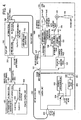
- FIG. 11 illustrates the configuration of an image-taking device to which the seventh embodiment of the present invention has been applied.
- reference numeral 100 denotes an exchangeable lens unit
- 200 denotes a camera unit
- 300 denotes a picture coaxial cable
- 400 denotes a remote control unit for supplying the lens unit 100 with control signals for controlling an unshown zoom lens unit, iris unit, and focus lens 106 within the lens unit 100, and with switching signals for switching between whether to control the unshown zoom lens unit, iris unit, and focus lens 106 with speed control or with positional control
- 500 denotes a remote control cable for connecting the remote control unit 400 with the lens unit 100.
- reference numeral 101 denotes a picture input terminal for inputting picture signals via a picture coaxial cable 300
- 102 denotes evaluation value generating means for extracting a sharpness evaluation value from the picture signals input from the picture input terminal 101
- 103 denotes AF driving control means for generating motor control signals such that the sharpness evaluation value generated by the evaluation value generating means 102 is maximized.
- Reference numeral 104 denotes AF/MF switching means controlled by later-described switching signal determining means 108, for switching between whether to drive the later-described motor 105 with motor control signals from the AF driving control means 103 or with motor control signals from the later-described MF driving control means 109, 105 denotes a motor operated by motor control signals from the AF driving control means 103 or the later-described MF driving control means 109, and 106 denotes a focus lens which moves along the optical axis by being driven by the motor 105.
- Reference numeral 107 denotes a remote control input terminal for inputting MF command signals and S/P switching signals from the remote control,unit 400 to the lens unit 100
- 108 denotes switching signal determining means for determining whether signals from later-described control setting means 110 are AF control or MF control, and in the event of MF control whether speed control or positional control of the focus lens 106 is to be performed, outputting S/P switching command signals commanding whether to control the focus lens 106 with speed control or positional control and also switching the AF/MF switching means 104 according to whether the focus lens 106 is to be controlled with AF control or MF control.
- Reference numeral 109 denotes MF driving control means for generating motor control signals for driving the motor 105 with MF control signals to control the focus lens 106 with one or the other of speed control or positional control, based on S/P switching command signals from the switching signal determining means 108, 110 denotes AF/MF control setting means for setting whether to control the focus lens 106 with AF control or MF control, and 111 denotes AF/MF control setting state display means for displaying the setting state of the AF/MF control setting means 110.
- reference numeral 201 denotes a CCD
- 202 denotes process means for converting the output signals of the CCD into a picture format such as NTSC signals or the like
- 203 denotes recording/reproducing means for recording the picture signals, which are the output of the process means 202, on a recording medium, and reproducing the pictures recorded therein.
- Reference numeral 204 denotes output switching means for selecting one of the process means 202 and recording/reproducing means 203 for output of the picture signals
- 205 denotes a picture output terminal for outputting picture signals which are the output of the output switching means 204.
- reference numeral 401 denotes MF command signal generating means configured of switches and dials for generating MF command signals
- 402 denotes S/P switching signal input means for switching between whether the focus lens 106 is to be controlled with speed control or positional control when under MF control
- 403 denotes a remote control output terminal for outputting the MF command signals and S/P switching signals from the remote control unit 400 to the lens unit 100.
- the optical flux through the focus lens 106 is imaged on the imaging face of the CCD 201, subjected to photoelectric conversion by the CCD 201, and a held sample is input to the process means 202.
- the input signals are converted into a picture format such as NTSC signals or the like, and output to the output switching means 204 and recording/reproducing means 203.
- the output switching means 204 output the output for the process means 202 to the picture output terminal 205, and the recording/reproducing means 203 record the output of the process means 202 to the recording medium.
- the recording/reproducing means 203 reproduce the picture signals recorded in the recording medium, and upon the picture signals being reproduced in a stable manner, the output switching means 204 output the picture signals of the recording/reproducing means 203 to the picture output terminal 205.
- Picture signals are input to the picture input terminal 101 of the lens 100 from the picture output terminal 205 of the camera 200 via the picture coaxial cable 300.
- the evaluation value generating means 102 generates sharpness evaluation values for the picture signals input to the picture input terminal 101, relating to the frequency component of the picture being obtained by filter processing or the like and generated in increments of vertical synchronization cycles of the picture signals, and output the sharpness evaluation values to the AF driving control means 103.
- the AF/MF control setting means 110 is set to drive the focus lens 106 with AF control, so Vref3 is input to the switching signal determining means 108 and the AF/MF control setting state display means 111 display AF control.
- the signal from the AF/MF control setting means 110 is Vref3, so the switching signal determining means 108 switch the AF/MF switching means 104 to the A side so as to control the focus lens 106 with AF control.
- the motor 105 is driven by motor control signals from the AF driving control means 103, and thus the focus lens 106 is moved.
- MF command signal generating means 401 configured of switches and dials and the like causes MF command signals proportionate to the operations thereof to be output, and input to the MF driving control means 109 via the remote control output terminal 403, remote control cable 500, and remote control input terminal 107.
- S/P switching signals for switching between whether to control the focus lens 106 with speed control or with positional control are input to the switching signal determining means 108 via the remote control output terminal 403, remote control cable 500, and remote control input terminal 107.
- the AF/MF control setting means 110 are set to control the focus lens 106 with MF control, so Vref3 is not input to the switching signal determining means 108, and the AF/MF control setting state display means 111 display MF control.
- Vref3 is not input from the AF/MF control setting means 110, so the AF/MF switching means 104 are switched to the B side so as to control the focus lens 106 with MF control.
- the input S/P switching signal is Vref1 determination is made to control the focus lens 106 with speed control, and an S/P switching command signal for controlling the focus lens 106 with speed control is output to the MF driving control means 109, and in the event that the input S/P switching signal is Vref2, determination is made to control the focus lens 106 with positional control, and an S/P switching command signal for controlling the focus lens 106 with positional control is output to the MF driving control means 109.
- the MF driving control means 109 handle the MF command signals as speed control command signals, generate motor control signals for driving the motor 105 at a speed specified with the MF command signals, and drive the motor 105 to move the focus lens 106.
- the MF driving control means 109 handle the MF command signals as positional control command signals, generate motor control signals for driving the motor 105 to the position specified with the MF command signals, and drive the motor 105 to move the focus lens 106.
- the embodiment may be similarly applied to an integrally formed camera unit having a non-detachable lens unit.
- the remote system with AF control is arranged so as to allow switching means for switching between whether to control the focus lens 106 with AF control or with MF control to be provided on the lens unit, even though there are no available pins in the electric interface between the remote control unit and the optical device, thereby making the remote system more useful.
- an optical device with a configuration comprising command/switching signal determining means for switching the control of the focus lens to MF control upon the MF command signals generating means being operated even though the AF/MF control setting means are set to AF control for controlling the focus lens will be described as an eighth embodiment.
- Fig. 12 illustrates the configuration of an optical device to which the eighth embodiment of the present invention has been applied.
- the components denoted by the reference numerals 100 through 107, 109, 110, 200 through 205, 300, 400 through 403, and 500 have already been described above, so description thereof will be omitted.
- Reference numeral 112 denotes command/switching signal determining means for determining whether a signal from the AF/MF control setting means 110 is for AF control or MF control, and further in the event that the signal is for AF control, determining whether or not the MF command signal generating means 401 have been operated, and in the event that the signal is for MF control, determining whether to control the focus lens 106 with speed control or with positional control, and further yet outputting S/P switching command signals to the MF driving control means 109 indicating whether to control the focus lens 106 with speed control or with positional control, and switching the AF/MF switching means 104 according to whether the focus lens 106 is to be controlled with AF control or with MF control.
- Reference numeral 113 denotes AF/MF control state display means for displaying whether the focus lens 106 is being controlled with AF control or with MF control.
- the optical flux through the focus lens 106 is imaged on the imaging face of the CCD 201, subjected to photoelectric conversion by the CCD 201, and a held sample is input to process means 202.
- the input signals are converted into a picture format such as NTSC signals or the like, and output to the output switching means 204 and recording/reproducing means 203.
- the output switching means 204 provides the output to the process means 202 to the picture output terminal 205, and the recording/reproducing means 203 record the output of the process means 202 to the recording medium.
- the recording/reproducing means 203 reproduce the picture signals recorded in the recording medium, and upon the picture signals being reproduced in a stable manner, the output switching means 204 output the picture signals of the recording/reproducing means 203 to the picture output terminal 205.
- Picture signals are input to the picture input terminal 101 of the lens 100 from the picture output terminal 205 of the camera 200 via the picture coaxial cable 300.
- the evaluation value generating means 102 generates sharpness evaluation values for the picture signals input to the picture input terminal 101, relating to the frequency component of the picture being obtained by filter processing or the like and generated in increments of vertical synchronization cycles of the picture signals, and output the sharpness evaluation values to the AF driving control means 103.
- the AF/MF control setting means 110 is set to drive the focus lens 106 with AF control, so Vref3 is input to the command/switching signal determining means 112.
- the signal from the AF/MF control setting means 110 is Vref3, so the command/switching signal determining means 112 switch the AF/MF switching means 104 to the A side so as to control the focus lens 106 with AF control and the AF/MF control state display means 113 display AF control.
- the motor 105 is driven by motor control signals from the AF driving control means 103, and thus the focus lens 106 is moved.
- the command/switching signal determining means 112 determine that the MF command signal from the MF command signal generating means 401 has changed, the AF/MF switching means 104 are switched to the B side, and MF control is displayed at the AF/MF control state display means 113.
- the command/switching signal determining means 112 output S/P switching command signals to the MF driving control means 109 so that control of the focus lens 106 is performed with speed control, and in the event that the S/P switching setting signal is Vref2, with positional control.
- the MF driving control means 109 handle the MF command signals as speed control command signals, generate motor control signals for driving the motor 105 at a speed specified with the MF command signals, and drive the motor 105 to move the focus lens 106.
- the MF driving control means 109 handle the MF command signals as positional control command signals, generate motor control signals for driving the motor 105 to the position specified with the MF command signals, and drive the motor 105 to move the focus lens 106.
- MF command signal generating means 401 configured of switches and dials and the like causes MF command signals proportionate to the operations thereof to be output, and input to the input to the MF driving control means 109 via the remote control output terminal 403, remote control cable 500, and remote control input terminal 107.
- S/P switching signals for switching between whether to control the focus lens 106 with speed control or with positional control are input to the command/switching signal determining means 112 via the remote control output terminal 403, remote control cable 500, and remote control input terminal 107.
- the AF/MF control setting means 110 are set to control the focus lens 106 with MF control, so Vref3 is not input to the command/switching signal determining means 112.
- Vref3 is not input from the AF/MF control setting means 110, so the AF/MF switching means 104 are switched to the B side so as to control the focus lens 106 with MF control and the AF/MF control state display means 113 display MF control.
- the input S/P switching signal is Vref1
- determination is made to control the focus lens 106 with speed control, and an S/P switching command signal for controlling the focus lens 106 with speed control is output to the MF driving control means 109
- determination is made to control the focus lens 106 with positional control, and an S/P switching command signal for controlling the focus lens 106 with positional control is output to the MF driving control means 109.
- the MF driving control means 109 handle the MF command signals as speed control command signals, generate motor control signals for driving the motor 105 at a speed specified with the MF command signals, and drive the motor 105 to move the focus lens 106.
- the MF driving control means 109 handle the MF command signals as positional control command signals, generate motor control signals for driving the motor 105 to the position specified with the MF command signals, and drive the motor 105 to move the focus lens 106.
- the embodiment may be similarly applied to an integrally formed camera unit having a non-detachable lens unit.
- AF/MF control state display means 113 display whether the focus lens 106 is being controlled with AF control or with MF control
- an arrangement may be made wherein the AF/MF control state display means 113 display whether the AF/MF control setting means 110 are set to AF control or to MF control.
- the remote system with AF control is arranged so as to allow switching means for switching between whether to control the focus lens with AF control or with MF control to be provided on the lens unit, even though there are no available pins in the electric interface between the remote control unit and the optical device, further enabling MF control when under AF control, thereby making the remote system more useful.
- the eighth embodiment has been described as an arrangement wherein, even in the event that the settings of the AF/MF control setting means are to control the focus lens with AF control, operating the MF command signal generating means switches the control of the focus lens to MF control by setting the S/P switching signal input means.
- a ninth embodiment will be descried as an optical device wherein in the event that the MF command signal generating means are operated under settings of the AF/MF control setting means to control the focus lens with AF control, the control of the focus lens to MF control is set to MF control only in the event that the setting of the S/P switching signal input means are to control the focus lens with speed control.
- Fig. 12 illustrates the configuration of an optical device to which the ninth embodiment of the present invention has been applied.
- the components denoted by the reference numerals 100 through 107, 109, 110, 112, 113, 200 through 205, 300, 400 through 403, and 500 have already been described above, so description thereof will be omitted.
- the MF command signal generating means 401 are operated while the focus lens 106 is being controlled with AF control, and in the event that the command/switching signal determining means 112 determines that the MF command signal from the MF command signal generating means 401 has changed and the S/P switching signal input from the S/P switching signal input means 402 is Vref1 the AF/MF switching means 104 are switched to the B side, and MF control is displayed at the AF/MF control state display means 113. In the event that the S/P switching signal input from the S/P switching signal input means 402 is Vref3, or the MF command signal generating means 401 have not been operated, the AF/MF switching means 104 go to the A side.
- the command/switching signal determining means 112 output a S/P switching command signal to the MF driving control means 109 to control the focus lens 106 with speed control.
- the MF driving control means 109 handle the MF command signals as speed control command signals, generate motor control signals for driving the motor 105 at a speed specified with the MF command signals, and drive the motor 105 to move the focus lens 106.
- the focus lens 106 is being controlled with MF control, so the AF/MF control state display means 113 display MF control.
- the embodiment may be similarly applied to an integrally formed camera unit having a non-detachable lens unit.
- AF/MF control state display means 113 display whether the focus lens 106 is being controlled with AF control or with MF control
- an arrangement may be made wherein the AF/MF control state display means 113 display whether the AF/MF control setting means 110 are set to AF control or to MF control.
- the remote system with AF control is arranged so as to allow switching means for switching control of the focus lens between AF control and MF control to be provided on the lens unit, even though there are no available pins in the electric interface between the remote control unit and the optical device, further enabling MF control when under AF control, thereby making the remote system more useful.
Abstract
Description
- The present invention relates to relay units and more specifically to relay units for optical devices for use in television cameras, video cameras, television lens, video lens, or the like, which perform automatic focal point detection focus control (hereafter referred to as "AF control").
- In recent years, automatic focal point detection control (AF) control has become indispensable to picture-taking devices such as consumer-grade video cameras or the like. The AF control method extracts and evaluates signals corresponding to the sharpness of the subject from picture signals before automatic focal point detection is performed.
- An example of operations of such an AF control system is described with reference to Fig. 6. In Fig. 6,
reference numeral 600 denotes a camera with a non-detachable lens unit, 102 denotes evaluation value generating means for extracting a sharpness evaluation value from the picture signals output from later-described process means 202, and 103 denotes AF driving control means for generating motor control signals such that the sharpness evaluation value generated by the evaluation value generating means 102 is maximized.Reference numeral 105 denotes a motor operated under the control of the AF driving control means 103, and 106 denotes a focus lens which is driven along the optical axis by themotor 105.Reference numeral 201 denotes a CCD, 202 denotes process means for converting the output signals of the CCD into a picture format such as NTSC signals or the like, and 203 denotes recording/reproducing means for recording the picture signals, which are the output of the process means 202, on a recording medium, and reproducing the pictures recorded therein. - In the above-described configuration, the optical flux which has passed through the
focus lens 106 is imaged on the imaging face of theCCD 201 for photoelectric conversion by the CCD. A held sample is then input to the process means 202, where input signals are converted into a picture format such as NTSC signals or the like, and output to the evaluation value generating means 102 and the recording/reproducing means 203. The evaluation value generating means 102 generates sharpness evaluation values for the picture signals output to the evaluation value generating means 102, the sharpness evaluation values relating to the frequency component of the picture being obtained by filter processing or the like and generated in increments of vertical synchronization cycles of the picture signals, and output to the AF driving control means 103. At the AF driving control means 103, motor control signals are generated which move thefocus lens 106 to a position wherein the sharpness evaluation value is maximum, sequentially comparing the sharpness evaluation value in increments of vertical synchronization cycles while driving themotor 105, so that thefocus lens 106 is moved to the focal point. The recording/reproducing means 203 records the output of the process means 202 in the recording medium, and also reproduce the pictures recorded therein. - An example of such AF driving will be described. The movement direction of the
focus lens 106 is determined by moving thefocus lens 106 by a small amount. That is, the focal point may either be at the far side of the near side of the current position of thefocus lens 106 or the near side of the focus lens. By slightly moving thefocus lens 106, and considering the change in the sharpness evaluation value, such movement direction is determined. Subsequently, thefocus lens 106 is moved at a specific speed in order to detect the peak value of the sharpness evaluation value, following the results of determining the direction for driving. This is referred to as "hill-climbing determination". After exceeding the peak value, the direction of moving thefocus lens 106 is reversed, and thefocus lens 106 is guided in increments of minute amounts of movement so that the sharpness evaluation value is maximized. This is referred to as "peak determination". Following the peak determination, the sharpness evaluation value is read and compared with the value immediately following the peak determination, and the value has changed, the AF operations are reactivated. - The video AF actions of a camera system having such an exchangeable lens configuration is described in detail in Japanese Unexamined Patent Application Publication No. 9-065184.
- Also, "remote systems" are known for monitoring and/or taking pictures of ceremonies or other solemn services or gatherings, etc., by using television cameras, video cameras, television lenses, video lenses, and so forth. Such remote systems are not equipped with AF control, and thus require an operator to operate switches and dials to perform functions such as zooming, iris control, focus, and so forth.
- A remote system uses a 12-pin electric interface between the remote control unit and the camera. The electric interface has pins assigned to zoom, iris, and focus command signals, control mode signals (switching between speed control and position control), electric power source, ground, and so forth. In may such remote systems, all 12 pins are in use, i.e., there are no more pins available.
- An example of operations of this remote system is described with reference to Fig. 7. The components in Fig. 7 denoted by the
reference numerals - In Fig. 7,
reference numeral 100 denotes an exchangeable lens unit, 200 denotes a camera unit, and 400 denotes a remote control unit for supplying to the lens unit 100: command signals for controlling an unshown zoom lens unit, iris unit, andfocus lens 106; and switching signals for switching between either speed control or positional control to control the unshown zoom lens unit, iris unit, andfocus lens 106.Reference numeral 500 denotes a remote control cable connecting thelens unit 100 and theremote control unit 400. - In the
lens unit 100,reference numeral 107 denotes a remote control input terminal for inputting to thelens unit 100 the command signals and switching signals from theremote control unit motor 105 from manual focus command signals (hereafter referred to as "MF command signals") input from theremote control unit focus lens 106 with either speed control or positional control, based on S/P switching signals output from S/P switching signal input means 402. - In the
remote control unit 400,reference numeral 401 denotes MF command signal generating means comprising switches and dials and the like for generating MF command signals, 402 denotes S/P switching signal input means to switch between control of thefocus lens 106 with either speed control or positional control, and 403 denotes a remote control output terminal for outputting the MF command signals and S/P switching signals from theremote control unit 400 to thelens unit 100. - In the above-described configuration, operating the MF command signal generating means 401 causes MF command signals proportionate to the operations thereof to be output, and input to the MF driving control means 109 via the remote
control input terminal 107. Also, S/P switching signals for switching between speed or positional control offocus lens 106 are output at the S/P switching signal input means 702, and input to the S/P switching signal determining means 211 via the remotecontrol output terminal 403, theremote control cable 500, and the remotecontrol input terminal 107. At the S/P switching signal determining means 211, determination is made regarding whether to control thefocus lens 106 with speed control or with positional control, and the determination results are output to the MF driving control means 109 as S/P switching command signals. At the MF driving control means 109, in the event that the S/P switching command signals are for controlling thefocus lens 106 with speed control, the MF command signals are handled as speed control commands signals, motor control signals are generated for driving themotor 105 at a speed commanded by the MF command signals, and themotor 105 is driven so as to move thefocus lens 106. On the other hand, in the event that the S/P switching command signals are for controlling thefocus lens 106 with positional control, the MF command signals are handled as positional control commands signals, motor control signals are generated for driving themotor 105 to the position commanded by the MF command signals, and themotor 105 is driven so as to move thefocus lens 106. - However, with the above-described conventional example, in the event that the remote system has AF control, simply replacing the
lens unit 100 with a lens unit capable of handling AF control does not provide the remote control unit 400 (which also enables remote operations of the lens unit 100) with switching means to determine whether thefocus lens 106 is to be driven by AF control or MF control. - Also, with the remote system, there are no pins available in the electric interface between the
remote control unit 400 and thelens unit 100, so pins cannot be assigned to switching signals to drive thefocus lens 106 either by AF control or by MF control from theremote control unit 400. - The present invention has been made in light of the above-described problems, and accordingly, it is a first concern of the present invention to provide a remote system with AF control. This AF control enables switching between AF or MF control of the
focus lens 106. the AF control unit is provided on the side of theremote control unit 400, which enables remote operations of thelens unit 100 simply by replacing thelens unit 100 with an AF control device. This allows switching between AF or MF of thefocus lens 106 despite the non-availability of pins in the electric interface between the remote control unit and the optical device. - According to a first aspect of the present invention, a relay unit connected between a remote control unit and an optical device having a focus lens is provided. The relay control unit comprises first switching signal input means for switching control of the focus lens between either an automatic focal point detection control or remote control from the remote control unit.
- According to this arrangement, a remote system with AF control is provided which has a switching means for switching between AF control and MF control of the focal lens.
- According to another aspect of the present invention, an optical device comprises: focal point detection focus control means for controlling a focus lens by automatic focal point detection focus control; and switching signal input means for switching between whether to control the focus lens by automatic focal point detection focus control or to control the focus lens by remote command control from remote command control means disposed outside of the optical device.
- According to another aspect, a relay unit locatable between a remote control unit and an optical device having a focus lens is provided. The relay unit includes a first switching signal input means for switching control of said focus lens between an automatic focal point detection focus control means and a remote control unit.
The automatic focal point detection focus control means performs automatic focal point detection focusing and the remote control unit provides remote commands to control the focus lens. - According to another aspect, a relay unit having an input terminal for receiving a manual focus command signal and a speed/position switching signal is provided. These signals may emanate from a remote control unit coupled to the relay unit, for example. The relay unit also has an output terminal for providing said manual focus command signal and said speed/position switching signal to a focus lens of an optical device. Another feature of the relay unit is that it has a switching signal input means for controlling the focus lens by switching between automatic focal point detection control and manual focus control of the focus lens.
- This enables an arrangement wherein switching means for switching between whether to drive the focus lens with AF control or with MF control to be provided to a lens unit of a remote system with AF control even though there are no available pins in the electric interface between the remote control unit and the optical device, thereby making the remote system more useful.
- Further features and advantages of the present invention will become apparent from the following description of the preferred embodiments with reference to the attached drawings.
- Fig. 1 is a block diagram of a first embodiment of the present invention.
- Fig. 2 is a block diagram of a second embodiment of the present invention.
- Fig. 3 is a multiplex signal diagram of signals from a relay unit.
- Fig. 4 is a block diagram of a third embodiment of the present invention.
- Fig. 5 is a block diagram of a fourth embodiment of the present invention.
- Fig. 6 is a first block diagram of a conventional example.
- Fig. 7 is a second block diagram of a conventional example.
- Fig. 8 is a block diagram of a fifth embodiment of the present invention.
- Fig. 9 is a switching signal diagram of signals from the relay unit.
- Fig. 10 is a block diagram of a sixth embodiment of the present invention.
- Fig. 11 is a block diagram of a seventh embodiment of the present invention.
- Fig. 12 is a block diagram illustrating eighth and ninth embodiments of the present invention.
- Fig. 13 is a block diagram of a conventional example.
- A description will now be made of embodiments of the present invention.
- A first embodiment of the present invention will now be described. Fig. 1 illustrates the configuration of an optical device to which the first embodiment of the present invention has been applied.
- In Fig. 1,
reference numeral 100 denotes an exchangeable lens unit, 200 denotes a camera unit, 300 denotes a picture coaxial cable. Thereference numeral 400 denotes a remote control unit for supplying thelens unit 100 with control signals for controlling a zoom lens unit and iris unit (not shown), and focuslens 106 within thelens unit 100. Theremote control unit 400 also supplies switching signals for switching between control of the zoom lens unit, iris unit, and focuslens 106 between speed control and positional control.
Thereference numeral 500 denotes a remote control cable for connecting theremote control unit 400 with arelay unit 700, which in turn is situated between theremote control unit 400 and thelens unit 100 and multiplexes switching signals for switching control of thefocus lens 106 between AF control or MF control upon S/P switching signals which are the output from S/P switching signal input means 402, and displays whether thefocus lens 106 is being controlled with AF control or MF control, and 800 denotes a relay unit cable for connecting therelay unit 700 and thelens unit 100. - In the
lens unit 100,reference numeral 101 denotes a picture input terminal for inputting picture signals via a picturecoaxial cable picture input terminal Reference numeral 104 denotes AF/MF switching means controlled by switching signal determining means 108, for switching between whether to drive the later-describedmotor 105 with motor control signals from the AF driving control means 103 or with motor control signals from the MF driving control means 109, 105 denotes a motor operated under the control of signals from the AF driving control means 103 or the later-described MF driving control means 109, and 106 denotes a focus lens which moves along the optical axis by being driven by themotor 105. -
Reference numeral 107 denotes a remote control input terminal for inputting MF command signals and multiplex signals from therelay unit 700 to thelens unit focus lens 106 is to be performed, outputting S/P switching command signals commanding later-described MF driving control means whether to control thefocus lens 106 with speed control or positional control and also switching the AF/MF switching means 104 according to whether thefocus lens 106 is to be controlled with speed control or positional control.Reference numeral 109 denotes MF driving control means for generating motor control signals for driving themotor 105 with MF control signals to control thefocus lens 106 with one or the other of speed control or positional control, based on S/P switching command signals from the switching signal determining means 108. - In the
camera 200,reference numeral 201 denotes a CCD, 202 denotes process means for converting the output signals of the CCD into a picture format such as NTSC signals or the like, and 203 denotes recording/reproducing means for recording the picture signals, which are the output of the process means 202, on a recording medium, and reproducing the pictures recorded therein.Reference numeral 204 denotes output switching means for selecting one of the process means 202 and recording/reproducingmeans 203 for output of the picture signals, and 205 denotes a picture output terminal for outputting picture signals which are the output of the output switching means. - In the
remote control unit 400,reference numeral 401 denotes MF command signal generating means configured of switches and dials for generating MF command signals, 402 denotes S/P switching signal input means for switching between whether thefocus lens 106 is to be controlled with speed control or positional control when under MF control, and 403 denotes a remote control output terminal for outputting the MF command signals and S/P switching signals from theremote control unit 400 to therelay unit 700. - In the
relay unit 700,reference numeral 701 denotes AF/MF switching signal input means for switching between whether to control thefocus lens 106 with AF control or MF control, 702 denotes AF/MF setting state display means for displaying which setting the AF/MF switching signal input means 701 are set to, i.e., whether to control thefocus lens 106 with AF control or MF control, 703 denotes a relay unit input terminal for inputting the MF command signals and S/P switching signals from theremote control unit 400 into therelay unit relay unit 700 to thelens unit 100. - Now, the manner in which the above-described configuration acts in the event of the AF/MF switching signal input means 701 being set so that the
focus lens 106 is controlled by AF control in a case wherein the MF command signal generating means 401 have not been operated, will be described. - The optical flux through the
focus lens 106 is imaged on the imaging face of theCCD 201, subjected to photoelectric conversion by theCCD 201, and a held sample is input to process means 202. At the process means 202, the input signals are converted into a picture format such as NTSC signals or the like, and output to the output switching means 204 and recording/reproducingmeans 203. In a recording state, the output switching means 204 output the output for the process means 202 to thepicture output terminal 205, and the recording/reproducingmeans 203 record the output of the process means 202 to the recording medium. In a reproducing state, the recording/reproducingmeans 203 reproduce the picture signals recorded in the recording medium, and upon the picture signals being reproduced in a stable manner, the output switching means 204 output the picture signals of the recording/reproducingmeans 203 to thepicture output terminal 205. - Picture signals are input to the
picture input terminal 101 of thelens 100 from thepicture output terminal 205 of thecamera 200 via the picturecoaxial cable 300. The evaluation value generating means 102 generates sharpness evaluation values for the picture signals input to thepicture input terminal 101, relating to the frequency component of the picture being obtained by filter processing or the like and generated in increments of vertical synchronization cycles of the picture signals, and output the sharpness evaluation values to the AF driving control means 103. - On the other hand, the AF/MF switching signal input means 701 of the
relay unit 700 is set to drive thefocus lens 106 with AF control, so AF control is displayed on the AF/MF setting state display means 702, and regardless of the state of the S/P switching signal input means 402 a multiplex signal Vref3, which differs from Vref1 or Vref2 is output from the AF/MF switching signal input means 701 to thelens unit 100 and input to the switching signal determining means 108 via the relayunit output terminal 704,relay unit cable 800, and remotecontrol input terminal 107. The switching signal determining means 108 determine the multiplex signals Vref3, and accordingly switch the AF/MF switching means 104 to the A side so as to control thefocus lens 106 with AF control. Accordingly, themotor 105 is driven by motor control signals from the AF driving control means 103, and thus thefocus lens 106 is moved. - Next, description will be made regarding actions in a case wherein, in the above state, the MF command signal generating means 401 are operated. In the event that the MF command signal generating means 401 are operated while the
focus lens 106 is being controlled by AF control, the switching signal determining means 108 determine that the MF command signals from the MF command signal generating means 401 have changed, and switch the AF/MF switching means 104 to the B side. At the same time, at the switching signal determining means 108, in the event the multiplex signal input from the S/P switching signal input means 402 prior to the AF/MF switching signal input means 701 being switched to the AF control via the remotecontrol output terminal 403,remote control cable 500, relayunit input terminal 703, AF/MF switching signal input means 701, relayunit output terminal 704,relay unit cable 800, and remotecontrol input terminal 107, is Vref1 which is different to Vref2 and Vref3, control of thefocus lens 106 is performed with speed control, and in the event that the multiplex signal is Vref2 which is different to Vref1 and Vref3, S/P switching command signals are output to the MF driving control means 109 based on information stored beforehand regarding signals which indicate that control of thefocus lens 106 is to be performed with positional control. In the event that the S/P switching command signals indicate that thefocus lens 106 is to be controlled by speed control, the MF driving control means 109 handle the MF command signals as speed control command signals, generate motor control signals for driving themotor 105 at a speed specified with the MF command signals, and drive themotor 105 to move thefocus lens 106. On the other hand, in the event that the S/P switching command signals indicate that thefocus lens 106 is to be controlled by positional control, the MF driving control means 109 handle the MF command signals as positional control command signals, generate motor control signals for driving themotor 105 to the position specified with the MF command signals, and drive themotor 105 to move thefocus lens 106. - Finally, description will be made regarding the actions in a case wherein the
focus lens 106 has been set to being driven by MF control by the AF/MF switching signal input means 701. Operating the MF command signal generating means 401 configured of switches and dials and the like causes MF command signals proportionate to the operations thereof to be output from the MF command signal generating means 401, and input to the switching signal determining means 108 and the MF driving control means 109 via the remotecontrol output terminal 403,remote control cable 500, relayunit input terminal 703, relayunit output terminal 704,relay unit cable 800, and remotecontrol input terminal 107. - On the other hand, at the S/P switching signal input means 402, S/P switching signals for switching between whether to control the
focus lens 106 with speed control or with positional control are input to the AF/MF switching signal input means 701 via the remotecontrol output terminal 403,remote control cable 500, and relayunit input terminal 703. The AF/MF switching signal input means 701 are set to control thefocus lens 106 with MF control, so the S/P switching signals Vref1 and Vref2 from the S/P switching signal input means 402 are output as a multiplexed signal, and input to the switching signal determining means 108 via the relayunit output terminal 704,relay unit cable 800, and remotecontrol input terminal 107. Also, since the AF/MF switching signal input means 701 are set to control thefocus lens 106 with MF control, the AF/MF setting state display means 702 displays MF control. At the switching signal determining means 108, in the event that the input multiplexed signals are Vref1 which is different to Vref2 and Vref3, the AF/MF switching means 104 are switched to the B side so as to control thefocus lens 106 with MF control, determination is made to control thefocus lens 106 with speed control, and an S/P switching command signal for controlling thefocus lens 106 with speed control is output to the MF driving control means 109. Also at the switching signal determining means 108, in the event that the input multiplexed signals are Vref2 which is different to Vref1 and Vref3, the AF/MF switching means 104 are switched to the B side so as to control thefocus lens 106 with MF control, determination is made to control thefocus lens 106 with positional control, and an S/P switching command signal for controlling thefocus lens 106 with positional control is output to the MF driving control means 109. In the event that the S/P switching command signals indicate that thefocus lens 106 is to be controlled by speed control, the MF driving control means 109 handle the MF command signals as speed control command signals, generate motor control signals for driving themotor 105 at a speed specified with the MF command signals, and drive themotor 105 to move thefocus lens 106. On the other hand, in the event that the S/P switching command signals indicate that thefocus lens 106 is to be controlled by positional control, the MF driving control means 109 handle the MF command signals as positional control command signals, generate motor control signals for driving themotor 105 to the position specified with the MF command signals, and drive themotor 105 to move thefocus lens 106. - With the present embodiment, although a description has been made regarding an arrangement wherein, in the event that the MF command signal generating means 401 are operated while performing AF control of the
focus lens 106, MF control of thefocus lens 106 is performed, an arrangement may also be made wherein, in the event that the MF command signal generating means 401 are operated while performing AF control of thefocus lens 106, AF control of thefocus lens 106 is performed. - Also, with the present embodiment, although a description has been made regarding an arrangement wherein, in the event that the MF command signal generating means 401 are operated while controlling the
focus lens 106 with AF control, whether to control thefocus lens 106 control to speed control or position control is set according to the state of the S/P switching signal prior to the AF/MF switching signal input means 701 being switched to AF control, an arrangement may be made wherein in the event that the MF command signal generating means 401 are operated while controlling thefocus lens 106 with AF control, whether to control thefocus lens 106 control to speed control or position control is set to a fixed option, i.e., only one of speed control or position control. - Further, with the present embodiment, although a description has been made regarding an arrangement wherein the AF/MF setting state display means 702 display whether the AF/MF switching signal input means 701 are set to AF control or MF control, an arrangement may be made wherein the AF/MF setting state display means 702 display whether the
focus lens 106 is being controlled with AF control or MF control. - Moreover, with the present embodiment, although a description has been made regarding application to an exchangeable lens which is detachable from the camera unit, the embodiment may be similarly applied to an integrally-formed camera unit having a non-detachable lens unit.
- Moreover, with the present embodiment, although a description has been made with regard to an arraignment wherein the
relay unit cable 800 is connected to the remotecontrol input terminal 107 of thelens unit 100, the present invention is not restricted to this configuration, and therelay unit cable 800 may be connected to the remote control input terminal of thecamera unit 200. Note that this arrangement whereinrelay unit cable 800 is connected to the remote control input terminal of thecamera unit 200 can also be applied to the following second through ninth embodiments, as well. - According to such a configuration, the remote system with AF control is arranged so as to allow switching means for switching between whether to control the focus lens with AF control or with MF control to be provided to the side of the remote control unit which enables remote operations of the lens unit simply by replacing the lens unit with an article capable of handing AF control, thereby enabling including of switching means for switching between whether to control the focus lens with AF control or with MF control to be provided to the side of the remote control unit even though there are no available pins in the electric interface between the remote control unit and the optical device, further enabling MF control when under AF control, thereby making the remote system more useful.
- Of the first embodiment, the configuration wherein S/P switching signals can be input to the lens unit even in the event that the control of the focus lens is AF control due to the momentary action of the AF/MF switching signal input means, whereby MF control is given priority while the MF command signal generating means are operating under AF control of the focus lens and AF control is performed following operation of the MF command signal generating means, with speed control or position control to be performed for the focus lens being switchable at that time, will be described as the second embodiment of the optical device.
- The second embodiment of the present invention will now be described. Fig. 2 illustrates the configuration of an optical device to which the second embodiment of the present invention has been applied. The components denoted by the
reference numerals 100 through 109, 200 through 205, 300, 400 through 403, 500, 700, 703, 704, and 800 have already been described above, so description thereof will be omitted. -
Reference numeral 705 denotes AF/MF switching MOM signal input means which switch between whether to perform control of thefocus lens 106 with AF control or MF control by momentary action, and 706 denotes AF/MF state display means for displaying whether the control of thefocus lens 106 is being performed with AF control or with MF control. - The S/P switching signal state and focus lens control state output from the S/P switching signal input means 402 indicated by the multiplex signal output from the
relay unit 700 in the above-described configuration will be described with reference to Fig. 3. In this drawing, the solid line represents the multiplex signal output from therelay unit 700, the dotted line represents the voltage level of the switching signal, the one-dash broken lines represent the S/P switching signal state within the multiplex signal, and the two-dash broken lines represent the focus lens control state within the multiplex signal. - Vref1 which is different to Vref2 and Vref3, and Vref2 which is different to Vref1 and Vref3, are output as the output signals of the S/P switching signal input means 402. Here, Vref1 is a signal indicating that the control of the
focus lens 106 is to be performed with speed control, and Vref2 is a signal indicating that the control of thefocus lens 106 is to be performed with positional control. Also, each time the AF/MF switching MOM signal input means 705 go to Vref3 with momentary action, the AF/MF switching means 104 switch according to determination and instruction of the switching signal determining means 108, thereby alternating between AF control and MF control. - First, the S/P switching signal state sectioned off by the one-dash broken lines will be described. In the regions A and C, speed control is selected for the control of the
focus lens 106 since the multiplex signal is Vref1, and in the region B, positional control is selected for the control of thefocus lens 106 since the multiplex signal is Vref2. - Next, the focus lens control state sectioned off by the two-dash broken line will be described. The regions a and c are where the
focus lens 106 is being controlled under MF control, and the region b is where thefocus lens 106 is being controlled under AF control. - In the state that the
focus lens 106 is being controlled under MF control, MF control is executed by MF command signals from the MF command signal generating means 401 in the S/P switching signal state. However, even in the state that thefocus lens 106 is being controlled under AF control, in the event that the MF command signal generating means 401 are operated, MF control is executed by MF command signals from the MF command signal generating means 401 in the S/P switching signal state. - Now, the actions of the
focus lens 106 being driven under AF control by operating the AF/MF switching MOM signal input means 705 in a case wherein the MF command signal generating means 401 is not operated will be described. - The optical flux through the
focus lens 106 is imaged on the imaging face of theCCD 201, subjected to photoelectric conversion by theCCD 201, and a held sample is input to process means 202. At the process means 202, the input signals are converted into a picture format such as NTSC signals or the like, and output to the output switching means 204 and recording/reproducingmeans 203. In the recording state, the output switching means 204 output the output for the process means 202 to thepicture output terminal 205, and the recording/reproducingmeans 203 record the output of the process means 202 to the recording medium. In the reproducing state, the recording/reproducingmeans 203 reproduce the picture signals recorded in the recording medium, and upon the picture signals being reproduced in a stable manner, the output switching means 204 output the picture signals of the recording/reproducingmeans 203 to thepicture output terminal 205. - Picture signals are input to the
picture input terminal 101 of thelens 100 from thepicture output terminal 205 of thecamera 200 via the picturecoaxial cable 300. The evaluation value generating means 102 generates sharpness evaluation values for the picture signals input to thepicture input terminal 101, relating to the frequency component of the picture being obtained by filter processing or the like and generated in increments of vertical synchronization cycles of the picture signals, and output the sharpness evaluation values to the AF driving control means 103. The AF/MF switching means 104 are set to the A side, so the motor control signals output from the AF driving control means 103 drive themotor 105 via the AF/MF switching means 104, thereby moving thefocus lens 106. In this case, control of thefocus lens 106 is set to be performed under AF control, so the AF/MF state display means 706 make a display indicating AF control. - Next, description will be made regarding actions in a case wherein, in the above state, the MF command signal generating means 401 are operated. In the event that the MF command signal generating means 401 are operated while the
focus lens 106 is being controlled by AF control, the switching signal determining means 108 determine that the MF command signals from the MF command signal generating means 401 have changed, and switch the AF/MF switching means 104 to the B side. At the same time, at the switching signal determining means 108, in the event the multiplex signal input from the S/P switching signal input means 402 via the remotecontrol output terminal 403,remote control cable 500, relayunit input terminal 703, AF/MF switching MOM signal input means 705, relayunit output terminal 704,relay unit cable 800, and remotecontrol input terminal 107, is Vref1 which is different to Vref2 and Vref3, control of thefocus lens 106 is performed with speed control, and in the event that the multiplex signal is Vref2 which is different to Vref1 and Vref3, S/P switching command signals are output to the MF driving control means 109 whereby control of thefocus lens 106 is performed with positional control. In the event that the S/P switching command signals indicate that thefocus lens 106 is to be controlled by speed control, the MF driving control means 109 handle the MF command signals as speed control command signals, generate motor control signals for driving themotor 105 at a speed specified with the MF command signals, and drive themotor 105 to move thefocus lens 106. On the other hand, in the event that the S/P switching command signals indicate that thefocus lens 106 is to be controlled by positional control, the MF driving control means 109 handle the MF command signals as positional control command signals, generate motor control signals for driving themotor 105 to the position specified with the MF command signals, and drive themotor 105 to move thefocus lens 106. In this case, control of thefocus lens 106 is set to MF control, so the AF/MF state display means 706 means make a display indicating MF control. - Finally, description will be made regarding the actions in a case wherein the
focus lens 106 has been set to being driven by MF control by the AF/MF switching MOM signal input means 705. Operating the MF command signal generating means 401 configured of switches and dials and the like causes MF command signals proportionate to the operations thereof to be output from the MF command signals generating means 401, and input to the switching signal determining means 108 and the MF driving control means 109 via the remotecontrol output terminal 403,remote control cable 500, relayunit input terminal 703, relayunit output terminal 704,relay unit cable 800, and remotecontrol input terminal 107. - On the other hand, at the S/P switching signal input means 402, S/P switching signals for switching between whether to control the
focus lens 106 with speed control or with positional control are input to the AF/MF switching MOM signal input means 705 via the remotecontrol output terminal 403,remote control cable 500, and relayunit input terminal 703. At the AF/MF switching MOM signal input means 705, the input S/P switching signals Vref1 and Vref2 are output as a multiplexed signal, and input to the switching signal determining means 108 via the relayunit output terminal 704,relay unit cable 800, and remotecontrol input terminal 107. At the switching signal determining means 108, in the event that the input multiplexed signals are Vref1 which is different to Vref2 and Vref3, the AF/MF switching means 104 are switched to the B side so as to control thefocus lens 106 with MF control, determination is made to control thefocus lens 106 with speed control, and an S/P switching command signal for controlling thefocus lens 106 with speed control is output to the MF driving control means 109. Also at the switching signal determining means 108, in the event that the input multiplexed signals are Vref2 which is different to Vref1 and Vref3, the AF/MF switching means 104 are switched to the B side so as to control thefocus lens 106 with MF control, determination is made to control thefocus lens 106 with positional control, and an S/P switching command signal for controlling thefocus lens 106 with positional control is output to the MF driving control means 109. In the event that the S/P switching command signals indicate that thefocus lens 106 is to be controlled by speed control, the MF driving control means 109 handle the MF command signals as speed control command signals, generate motor control signals for driving themotor 105 at a speed specified with the MF command signals, and drive themotor 105 to move thefocus lens 106. On the other hand, in the event that the S/P switching command signals indicate that thefocus lens 106 is to be controlled by positional control, the MF driving control means 109 handle the MF command signals as positional control command signals, generate motor control signals for driving themotor 105 to the position specified with the MF command signals, and drive themotor 105 to move thefocus lens 106. In this case, control of thefocus lens 106 is set to MF control by the AF/MF switching MOM signal input means 705, so the AF/MF state display means 706 means make a display indicating MF control. - With the present embodiment, although a description has been made regarding an arrangement wherein, in the event that the MF command signal generating means 401 are operated while performing AF control of the
focus lens 106, MF control of the focus lens is performed, an arrangement may also be made wherein, in the event that the MF command signal generating means 401 are operated while performing AF control of thefocus lens 106, AF control of the focus lens is performed. - Also, with the present embodiment, although a description has been made regarding an arrangement wherein, in the event that the MF command signal generating means 401 are operated while controlling the
focus lens 106 with AF control, whether to control thefocus lens 106 control to speed control or position control is set according to the state of the S/P switching signal output from the S/P switching signal input means 402, an arrangement may be made wherein in the event that the MF command signal generating means 401 are operated while controlling thefocus lens 106 with AF control, whether to control thefocus lens 106 control to speed control or position control is set to a fixed option, i.e., only one of speed control or position control. - Further, with the present embodiment, although a description has been made regarding an arrangement wherein the AF/MF setting state display means 702 display whether the
focus lens 106 is being controlled with AF control or MF control, an arrangement may be made wherein the AF/MF setting state display means 702 display whether the AF/MF switching MOM signal input means 705 have set the control of thefocus lens 106 to AF control or to MF control. - Moreover, with the present embodiment, although a description has been made regarding application to an exchangeable lens which is detachable from the camera unit, the embodiment may be similarly applied to an integrally-formed camera unit having a non-detachable lens unit.
- According to such a configuration, the advantages of the above-described first embodiment can be had, i.e., the remote system with AF control is arranged so as to allow switching means for switching between whether to control the focus lens with AF control or with MF control to be provided to the side of the remote control unit which enables remote operations of the lens unit simply by replacing the lens unit with an article capable of handing AF control, thereby enabling including of switching means for switching between whether to control the focus lens with AF control or with MF control to be provided to the side of the remote control unit even though there are no available pins in the electric interface between the remote control unit and the optical device, further enabling MF control when under AF control, thereby making the remote system more useful.
- With the first embodiment, in the event that the MF command signal generating means are operated while control of the focus lens is being performed under AF control, MF control is performed based on S/P command signals recorded beforehand prior to the AF/MF switching signal input means being switched to AF control. A configuration comprising S/P switching setting means for switching between whether to control the focus lens with speed control or positional control in the event that the MF command signal generating means are operated while the focus lens of the lens unit is being controlled with AF control will be described as the third embodiment of the optical device.
- The third embodiment of the present invention will now be described. Fig. 4 illustrates the configuration of an optical device to which the third embodiment of the present invention has been applied. The components denoted by the
reference numerals 100 through 109, 200 through 205, 300, 400 through 403, 500, 700 through 704, and 800 have already been described above, so description thereof will be omitted. -
Reference numeral 110 denotes S/P switching setting means for switching between whether to perform MF control of the focus lens with speed control or positional control in the event that the MF command signal generating means 401 are operated while thefocus lens 106 is being controlled with AF control. - In the above-described configuration, the actions in the event that the settings of the AF/MF switching signal input means 701 are to control the
focus lens 106 with AF control, and the MF command signal generating means 401 are not operated, and the actions in the event that the settings are for thefocus lens 106 to be controlled with MF control by the AF/MF switching signal input means 701, are the same as those in the first embodiment, so description thereof will be omitted. Rather, the actions in a case wherein the settings of the AF/MF switching signal input means 701 are to control thefocus lens 106 with AF control, and the MF command signal generating means 401 are operated, will be described. - In the event that the MF command signal generating means 401 are operated while the
focus lens 106 is being controlled with AF control, the switching signal determining means 108 determines that the MF command signal from the MF command signal generating means 401 has changed, and the AF/MF switching means 104 are switched to the B side. At the same time, in the event that the S/P switching setting signal input from the S/P switching setting means 110 is Vref1 which is different to Vref2, control of thefocus lens 106 is performed with speed control, and in the event that the S/P switching setting signal input from the S/P switching setting means 110 is Vref2 which is different to Vref1, an S/P switching command signals for performing control of thefocus lens 106 with positional control is output to the MF driving control means 109. At the MF driving control means 109, in the event that the S/P switching command signals indicate that thefocus lens 106 is to be controlled by speed control, the MF driving control means 109 handle the MF command signals as speed control command signals, generate motor control signals for driving themotor 105 at a speed specified with the MF command signals, and drive themotor 105 to move thefocus lens 106. On the other hand, in the event that the S/P switching command signals indicate that thefocus lens 106 is to be controlled by positional control, the MF driving control means 109 handle the MF command signals as positional control command signals, generate motor control signals for driving themotor 105 to the position specified with the MF command signals, and drive themotor 105 to move thefocus lens 106. - With the present embodiment, although a description has been made regarding application to an exchangeable lens, which is detachable from the camera unit, the embodiment may be similarly applied to an integrally formed camera unit having a non-detachable lens unit.
- According to such a configuration, the advantages of the above-described embodiments can be had, i.e., the remote system with AF control is arranged so as to allow switching means for switching between whether to control the focus lens with AF control or with MF control to be provided to the side of the remote control unit which enables remote operations of the lens unit simply by replacing the lens unit with an article capable of handing AF control, thereby enabling including of switching means for switching between whether to control the focus lens with AF control or with MF control to be provided to the side of the remote control unit even though there are no available pins in the electric interface between the remote control unit and the optical device, further enabling MF control when under AF control, thereby making the remote system more useful.
- In the event that the MF command signal generating means 401 disposed in the
remote control unit 400 has a mechanical effective rotational angle, and is a dial for generating MF positional command signals, the movable range of the MF command signal generating means 401 is limited.
In this case, the rotational angle of the dial corresponds to the position of thefocus lens 106 on a one-to-one basis. In the event of performing MF control from the MF command signal generating means 401 while thefocus lens 106 is being controlled by AF, the position of thefocus lens 106 before MF control and the position following MF control will not match. Accordingly, the MF command signal generating means 401 which perform MF control while thefocus lens 106 is being controlled with AF control is preferably MF speed command signals generating means. This holds the true for the above-described first through third embodiments and the following fifth through ninth embodiments as well. While thefocus lens 106 is controlled with MF control in the event that the MF command signal generating means 401 are operated while thefocus lens 106 is being controlled with AF control, a configuration wherein therelay unit 700 is provided with AF-MF speed command signal generating means 707 for generating MF speed command signals which are valid only in the event that thefocus lens 106 is being controlled with AF control will be described as the fourth embodiment of the optical device. - The fourth embodiment of the present invention will now be described. Fig. 5 illustrates the configuration of an optical device to which the fourth embodiment of the present invention has been applied. The components denoted by the
reference numerals 100 through 109, 200 through 205, 300, 400 through 403, 500, 700 through 704, and 800 have already been described above, so description thereof will be omitted. -
Reference numeral 707 denotes AF-MF speed command signal generating means disposed within therelay unit 700 for generating AF-MF speed command signals, for controlling the speed of thefocus lens 106, which are valid only in the event that thefocus lens 106 is being controlled with AF control. - In the above-described configuration, the actions under the settings that the AF/MF switching signal input means 701 are to control the
focus lens 106 with AF control, in the event that the AF-MF speed command signal generating means 707 are not operated, will be described. - The optical flux through the
focus lens 106 is imaged on the imaging face of theCCD 201, subjected to photoelectric conversion by theCCD 201, and a held sample is input to process means 202. At the process means 202, the input signals are converted into a picture format such as NTSC signals or the like, and output to the output switching means 204 and recording/reproducingmeans 203. In the recording state, the output switching means 204 output the output for the process means 202 to thepicture output terminal 205, and the recording/reproducingmeans 203 record the output of the process means 202 to the recording medium. In the reproducing state, the recording/reproducingmeans 203 reproduce the picture signals recorded in the recording medium, and upon the picture signals being reproduced in a stable manner, the output switching means 204 output the picture signals of the recording/reproducingmeans 203 to thepicture output terminal 205. - Picture signals are input to the
picture input terminal 101 of thelens 100 from thepicture output terminal 205 of thecamera 200 via the picturecoaxial cable 300. The evaluation value generating means 102 generates sharpness evaluation values for the picture signals input to thepicture input terminal 101, relating to the frequency component of the picture being obtained by filter processing or the like and generated in increments of vertical synchronization cycles of the picture signals, and output the sharpness evaluation values to the AF driving control means 103. - On the other hand, the AF/MF switching signal input means 701 of the
relay unit 700 are set so as to drive thefocus lens 106 with AF control, so AF control is displayed on the AF/MF setting state display means 702, and the multiplex switching signal Vref3 which is different from Vref1 and Vref2 is output to thelens unit 100 from the AF/MF switching signal input means 701 regardless'of the state of the S/P switching signal input means 402, and input to the switching signal determining means 108 via the relayunit output terminal 704,relay unit cable 800, and remotecontrol input terminal 107. At the switching signal determining means 108, the input multiplexed signals are Vref3, so the AF/MF switching means 104 are switched to the A side so as to control thefocus lens 106 with AF control. Thus, themotor 105 is driven by motor control signals from the AF driving control means 103, thereby moving thefocus lens 106. - Next, description will be made regarding actions in a case wherein, in the above state, the AF-MF speed command signal generating means 707 are operated. Operating the AF-MF speed command signal generating means 707 of the
relay unit 700, configured of switches and the like, causes AF-MF command signals proportionate to the operations of the AF-MF speed command signal generating means 707 to be output, and input as multiplex command signals from the AF/MF switching signal input means 701 to the switching signal determining means 108 and the MF driving control means 109 via the relayunit output terminal 704,relay unit cable 800, and remotecontrol input terminal 107. In the event that the AF-MF speed command signal generating means 707 are operated while thefocus lens 106 is being controlled with AF control, the switching signal determining means 108 determines that the multiplex command signals from the MF command signal generating means 401 have changed, and the AF/MF switching means 104 are switched to the B side. At the same time, at the switching signal determining means 108, the S/P switching command signal for controlling thefocus lens 106 with speed control is output to the MF driving control means 109. The S/P switching command signals indicate that thefocus lens 106 is to be controlled by speed control, so the MF driving control means 109 handle the multiplex command signals as speed control command signals, generate motor control signals for driving themotor 105 at a speed specified with the MF command signals, and drive themotor 105 to move thefocus lens 106. - Finally, description will be made regarding the actions in a case wherein the
focus lens 106 has been set to being driven by MF control by the AF/MF switching signal input means 701. Operating the MF command signal generating means 401 configured of switches and dials and the like causes MF command signals proportionate to the operations thereof to be output, and input to the input to the AF/MF switching signal input means 701 via the remotecontrol output terminal 403,remote control cable 500, and relayunit input terminal 703. The AF/MF switching signal input means 701 are set so as to drive thefocus lens 106 with MF control, so MF command signals are output as mult'iplex command signals from the MF command signal generating means 401, and input to the switching signal determining means 108 and MF driving control means 109 via the relayunit output terminal 704,relay unit cable 800, and remotecontrol input terminal 107. - On the other hand, at the S/P switching signal input means 402, S/P switching signals for switching between whether to control the
focus lens 106 with speed control or with positional control are input to the AF/MF switching signal input means 701 via the remotecontrol output terminal 403,remote control cable 500, and relayunit input terminal 703. At the AF/MF switching signal input means 701, control of thefocus lens 106 is set to MF control, so the input S/P switching signals Vref1 and Vref2 are output from the S/P switching signal input means 402 as a multiplexed signal, and input to the switching signal determining means 108 via the relayunit output terminal 704,relay unit cable 800, and remotecontrol input terminal 107. Also, the AF/MF switching signal input means 701 are set to control thefocus lens 106 with MF control, so MF control is displayed at the AF/MF setting state display means 702. At the switching signal determining means 108, in the event that the input multiplexed signals are Vref1 which is different to Vref2 and Vref3, the AF/MF switching means 104 are switched to the B side so as to control thefocus lens 106 with MF control, determination is made to control thefocus lens 106 with speed control, and an S/P switching command signal for controlling thefocus lens 106 with speed control is output to the MF driving control means 109. Also at the switching signal determining means 108, in the event that the input multiplexed signals are Vref2 which is different to Vref1 and Vref3, the AF/MF switching means 104 are switched to the B side so as to control thefocus lens 106 with MF control, determination is made to control thefocus lens 106 with positional control, and an S/P switching command signal for controlling thefocus lens 106 with positional control is output to the MF driving control means 109. In the event that the S/P switching command signals indicate that thefocus lens 106 is to be controlled by speed control, the MF driving control means 109 handle the MF command signals as speed control command signals, generate motor control signals for driving themotor 105 at a speed specified with the MF command signals, and drive themotor 105 to move thefocus lens 106. On the other hand, in the event that the S/P switching command signals indicate that thefocus lens 106 is to be controlled by positional control, the MF driving control means 109 handle the MF command signals as positional control command signals, generate motor control signals for driving themotor 105 to the position specified with the MF command signals, and drive themotor 105 to move thefocus lens 106. - With the present embodiment, although a description has been made regarding an arrangement wherein MF speed command signals, which are valid only in the event that the
focus lens 106 is being controlled with AF control, control thefocus lens 106 with speed control, an arrangement may be made wherein MF speed command signals which are valid only in the event that thefocus lens 106 is being controlled with AF control, control thefocus lens 106 with positional control. - With the present embodiment, although a description has been made regarding an arrangement wherein MF speed command signals, which are valid only in the event that the
focus lens 106 is being controlled with AF control, control thefocus lens 106 with speed control, an arrangement may be made wherein setting means having the functions equivalent to the S/P switching setting means described in the third embodiment are disposed within thelens unit 100, so that MF speed command signals which are valid only in the event that thefocus lens 106 is being controlled with AF control, control thefocus lens 106 with either speed control or positional control. - Also, with the present embodiment, although a description has been made regarding an arrangement wherein the AF/MF setting state display means 702 display whether the AF/MF switching signal input means 701 are set to AF control or MF control, an arrangement may be made wherein the AF/MF setting state display means 702 display whether the
focus lens 106 is being controlled with AF control or MF control. - Further, with the present embodiment, although a description has been made regarding application to an exchangeable lens which is detachable from the camera unit, the embodiment may be similarly applied to an integrally-formed camera unit having a non-detachable lens unit.
- According to such a configuration, the advantages of the above-described embodiments can be had, i.e., the remote system with AF control is arranged so as to allow switching means for switching between whether to control the focus lens with AF control or with MF control to be provided to the side of the remote control unit which enables remote operations of the lens unit simply by replacing the lens unit with an article capable of handing AF control, thereby enabling including of switching means for switching between whether to control the focus lens with AF control or with MF control to be provided to the side of the remote control unit even though there are no available pins in the electric interface between the remote control unit and the optical device, further enabling MF control when under AF control, thereby making the remote system more useful.
- A fifth embodiment of the present invention will now be described. Fig. 8 illustrates the configuration of an optical device to which the fifth embodiment of the present invention has been applied.
- In Fig. 8,
reference numeral 100 denotes an exchangeable lens unit, 200 denotes a camera unit, 300 denotes a picture coaxial cable, 400 denotes a remote control unit for supplying thelens unit 100 with control signals for controlling an unshown zoom lens unit, iris unit, and focuslens 106 within thelens unit 100, and with switching signals for switching between whether to control the unshown zoom lens unit, iris unit, and focuslens 106 with speed control or with positional control, 500 denotes a remote control cable for connecting theremote control unit 400 with a later-describedrelay unit 700, which in turn is situated between theremote control unit 400 and thelens unit 100 and multiplexes switching signals regarding whether to control thefocus lens 106 with AF control or MF control upon MF command signals which are the output from the MF command signal generating means 401, and displays whether thefocus lens 106 is being controlled with AF control or MF control, and 800 denotes a relay unit capable for connecting therelay unit 700 and thelens unit 100. - In the
lens unit 100,reference numeral 101 denotes a picture input terminal for inputting picture signals via a picturecoaxial cable Reference numeral 104 denotes AF/MF switching means controlled by later-described switching signal determining means 108, for switching between whether to drive thefocus lens 106 with motor control signals from the AF driving control means 103 or with motor control signals from the later-described MF driving control means 109, 105 denotes a motor operated with motor control signals from the AF driving control means 103 or the later-described MF driving control means 109, and 106 denotes a focus lens which moves along the optical axis by being driven by themotor 105.Reference numeral 107 denotes a remote control input terminal for inputting S/P switching signals and multiplex signals from therelay unit 700 to thelens unit focus lens 106 is to be performed, outputting S/P switching command signals commanding whether to control thefocus lens 106 with speed control or positional control to the MF driving control means 109 and also switching the AF/MF switching means according to whether thefocus lens 106 is to be controlled with AF control or MF control.Reference numeral 109 denotes MF driving control means for generating motor control signals for driving themotor 105 with MF control signals to control thefocus lens 106 with one or the other of speed control and positional control, based on S/P switching command signals from the switching signal determining means 108. - In the
camera 200,reference numeral 204 denotes output switching means for selecting one of the process means 202 and recording/reproducingmeans 203 for output of the picture signals, and 205 denotes a picture output terminal for outputting picture signals which are the output of the output switching means 204. - In the
remote control unit 400,reference numeral 401 denotes MF command signal generating means configured of switches and dials for generating MF command signals, 402 denotes S/P switching signal input means for switching between whether thefocus lens 106 is to be controlled with speed control or positional control, and 403 denotes a remote control output terminal for outputting the MF command signals and S/P switching signals from theremote control unit 400 to therelay unit 700. - In the
relay unit 700,reference numeral 701 denotes AF/MF switching signal input means for switching between whether to control thefocus lens 106 with AF control or MF control, 702 denotes AF/MF setting state display means for displaying which setting the AF/MF switching signal input means 701 are set to, i.e., whether to control thefocus lens 106 with AF control or MF control, 703 denotes a relay unit input terminal for inputting the MF command signals and S/P switching signals from theremote control unit 400 into therelay unit relay unit 700 to thelens unit 100. - Now, the manner in which the above-described configuration acts in the event of the AF/MF switching signal input means 701 being set so that the control signal for driving the
focus lens 106 is driven by the control signal from the AF driving control means 103, will be described. - The optical flux through the
focus lens 106 is imaged on the imaging face of theCCD 201, subjected to photoelectric conversion by theCCD 201, and a held sample is input to process means 202. At the process means 202, the input signals are converted into a picture format such as NTSC signals or the like, and output to the evaluation value generating means 102 and recording/reproducingmeans 203. The evaluation value generating means 102 generates sharpness evaluation values for the picture signals input thereto, relating to the frequency component of the picture being obtained by filter processing or the like and generated in increments of vertical synchronization cycles of the picture signals, and output the sharpness evaluation values to the AF driving control means 103. - On the other hand, the AF/MF switching signal input means 701 of the
relay unit 700 are set to drive thefocus lens 106 with control signals from the AF driving control means 103, so level signals outside of the output range of the MF command signal generating means 401 are output from the AF/MF switching signal input means 701. For example, in the event of controlling thefocus lens 106 with speed control in a MF command signal output range of the MF command signal generating means 401 of +2.5 V to +7.5 V, speed control is performed with +5.0 V serving as a stop signal and thefocus lens 106 is subjected to speed control toward the infinity side in the event that the signal is between +5.0 V to +7.5 V and toward the close-up side in the event that the signal is between +5.0 V to +2.5 V. Further, the speed is greater the farther the value is from +5.0 V, so thefocus lens 106 is driven at maximum speed in the event that the value is +7.5 V or +2.5 V. - Now, with the above-described arrangement, the signal whereby the AF/MF switching signal input means 701 sets the control signals from the AF driving control means 103 as the control signals for driving the
focus lens 106 is 0 V. The AF/MF switching signal input means 701 are set to control thefocus lens 106 with AF control, so AF control is displayed on the AF/MF setting state display means 702. The level signals outside of the output range of the MF command signal generating means 401 are input to the switching signal determining means 108 via the relayunit output terminal 704,relay unit cable 800, and remotecontrol input terminal 107, whereby the switching signal determining means 108 determine that the signals are level signals outside of the output range of the MF command signal generating means 401, and accordingly switch the AF/MF switching means 104 to the A side. Accordingly, themotor 105 is driven by motor control signals from the AF driving control means 103, and thus thefocus lens 106 is moved. - Next, description will be made regarding actions in a case wherein the S/P switching signal input means 402 are set to drive the
focus lens 106 with motor control signals from the MF driving control means 109. Operating the MF command signal generating means 401 configured of switches and dials and the like causes MF command signals proportionate to the operations thereof to be output, and input to the input means 701 via the remotecontrol output terminal 403,remote control cable 500, and relayunit input terminal 703. The AF/MF switching signal input means 701 are set to drive thefocus lens 106 with motor control signals from the MF driving control means 109, so the MF command signals from the MF command signal generating means 401 are output as multiplex command signals, and input to the switching signal determining means 108 and MF driving control means 109 via the relayunit output terminal 704,relay unit cable 800, and remotecontrol input terminal 107. The AF/MF switching signal input means 701 are set to control thefocus lens 106 with MF control, so MF control is displayed on the AF/MF setting state display means 702. Also, in the event that MF control is being performed to control the focus lens, S/P switching signals for setting whether to control the focus lens with speed control or with positional control are output from the S/P switching signal input means 402, and input to the switching signal determining means 108 via the remotecontrol output terminal 403,remote control cable 500, relayunit input terminal 703, relayunit output terminal 704,relay unit cable 800, and remotecontrol input terminal 107. Here, let us say that the S/P switching signal output is Vref1 in the event of controlling thefocus lens 106 with speed control, and Vref2 in the event of controlling thefocus lens 106 with positional control. The switching signal determining means 108 determine that the input multiplex signals are level signals within the output range of the MF command signal generating means 401, switch the AF/MF switching means 104 to the B side, and in the event that the input S/P switching signal Vref2 determines that control of thefocus lens 106 is to be made with positional control, and outputs a S/P switching command signal of positional control of thefocus lens 106 to the MF driving control means 109. In the event that the S/P switching command signals indicate that thefocus lens 106 is to be controlled by speed control, the MF driving control means 109 handle the MF command signals as speed control command signals, generate motor control signals for driving themotor 105 at a speed specified with the MF command signals, and drive themotor 105 to move thefocus lens 106. On the other hand, in the event that the S/P switching command signals indicate that thefocus lens 106 is to be controlled by positional control, the MF driving control means 109 handle the MF command signals as positional control command signals, generate motor control signals for driving themotor 105 to the position specified with the MF command signals, and drive themotor 105 to move thefocus lens 106. - With the present embodiment, although a description has been made regarding application to an exchangeable lens, which is detachable from the camera unit, the embodiment may be similarly applied to an integrally formed camera unit having a non-detachable lens unit.
- According to such a configuration, the advantages of the above-described embodiments can be had, i.e., the remote system with AF control is arranged so as to allow switching means for switching between whether to control the focus lens with AF control or with MF control to be provided to the side of the remote control unit which enables remote operations of the lens unit simply by replacing the lens unit with an article capable of handing AF control, thereby enabling including of switching means for switching between whether to control the focus lens with AF control or with MF control to be provided to the side of the remote control unit even though there are no available pins in the electric interface between the remote control unit and the optical device, further enabling MF control when under AF control, thereby making the remote system more useful.
- An optical device, having a configuration wherein the AF/MF switching signal input means of the fifth embodiment performs momentary actions, whereby MF command signals are input to the lens unit even in the event of controlling the focus lens with AF control, with MF control being given priority in the event that the MF command signal generating means are operated while controlling the focus lens under AF control, AF control then being performed at the point that the operations of the MF command signal generating means end, will be described as a sixth embodiment.
- The sixth embodiment of the present invention will now be described with reference to the drawings. Fig. 10 illustrates the configuration of an optical device to which the sixth embodiment of the present invention has been applied. The components denoted by the
reference numerals 100 through 109, 200 through 205, 300, 400 through 403, 500, 700, 703, 704, and 800 have already been described above, so description thereof will be omitted. -
Reference numeral 705 denotes AF/MF switching MOM signal input means which switch between whether to perform control of thefocus lens 106 with AF control or MF control by momentary action, and 706 denotes AF/MF state display means for displaying whether the control of thefocus lens 106 is being performed with AF control or with MF control. - With the above configuration, an example of the MF command signals from the MF command signal generating means 401 being speed control will be described with reference to Fig. 9, for each control state of the
focus lens 106, i.e., AF control and MF control. In this drawing, the solid line represents the multiplex signal output from therelay unit 700, the dotted line represents the voltage level of the multiplex signal, the one-dash broken lines represent the state of the MF command signals output from the MF command signal generating means 401 within theremote control unit 400, and the two-dash broken lines represent the AF action state under operations of the AF/MF switching MOM signal input means within therelay unit 700. - In the event of controlling the
focus lens 106 with speed control in a MF command signal output range of the MF command signal generating means 401 of +2.5 V to +7.5 V, speed control is performed with +5.0 V serving as a stop signal and thefocus lens 106 is subjected to speed control toward the infinity side in the event that the signal is between +5.0 V to +7.5 V and toward the close-up side in the event that the signal is between +5.0 V to +2.5 V. The speed is greater the farther the value is from +5.0 V, so thefocus lens 106 is driven at maximum speed in the event that the value is +7.5 V or +2.5 V. Each time the AF/MF switching MOM signal input means 705 go to 0 V in the momentary action, the AF/MF switching means 104 switch under determination made by the switching signal determining means 108, and AF control and MF control is alternately repeated. - First, the MF command signal state sectioned off by the single-dash broken line will be described. The symbols A, C, and E represent a state wherein the
focus lens 106 is stopped due to the remote control output signal being +5.0 V, B represents a state wherein thefocus lens 106 is driven toward the infinity side at full speed due to the remote control output signal being +7.5 V, and D represents a state wherein thefocus lens 106 is driven toward the close-up side at intermediate speed due to the remote control output signal being +3.75 V. - Next, the AF action state sectioned off by the two-dash broken line will be described. The regions a and c are where AF is off, and the region b is where AF is on.
- Finally, the control state of the
focus lens 106 will be described. In the regions a and c, AF is off so thefocus lens 106 is in the MF control state, in the region portion D in the region b thefocus lens 106 is in the MF control state because the MF command signal generating means 401 has been operated and MF command signals are being output, and in portions other than the region portion D in the region b thefocus lens 106 is in the AF control state. - Now, the actions in the event that the
focus lens 106 is set to be driven with AF control by the AF/MF switching MOM signal input means 705 being operated, will be described. - The optical flux through the focus lens'106 is imaged on the imaging face of the
CCD 201, subjected to photoelectric conversion by theCCD 201, and a held sample is input to process means 202. At the process means 202, the input signals are converted into a picture format such as NTSC signals or the like, and output to the evaluation value generating means 102 and recording/reproducingmeans 203. Picture signals are input to thepicture input terminal 101 of thelens 100 from thepicture output terminal 205 of thecamera 200 via the picturecoaxial cable 300. The evaluation value generating means 102 generates sharpness evaluation values for the picture signals input to thepicture input terminal 101, relating to the frequency component of the picture being obtained by filter processing or the like and generated in increments of vertical synchronization cycles of the picture signals, and output the sharpness evaluation values to the AF driving control means 103. The AF/MF switching means 104 are set to the A side, so the motor control signals output from the AF driving control means 103 drive themotor 105 via the AF/MF switching means 104, thereby moving thefocus lens 106. In this case, control of thefocus lens 106 is set to be performed under AF control by the AF/MF switching MOM signal input means 705 being operated, so the AF/MF state display means 706 make a display indicating AF control. - Next, a case wherein the
focus lens 106 is set to be driven with MF control by the AF/MF switching MOM signal input means 705 will be described. Operating the MF command signal generating means 401 configured of switches and dials and the like causes MF command signals proportionate to the operations thereof to be output, and input to the remotecontrol output terminal 403,remote control cable 500, relayunit input terminal 703, and AF/MF switching MOM signal input means 705. The AF/MF switching MOM signal input means 705 is set such that the control signals for driving thefocus lens 106 are the control signals from the MF driving control means 109, so the MF command signals from the MF command signal generating means 401 are output as multiplex command signals, and input to the switching signal determining means 108 and MF driving control means 109 via the relayunit output terminal 704,relay unit cable 800, and remotecontrol input terminal 107. The AF/MF switching MOM signal input means 705 are set to control thefocus lens 106 with MF control, so MF control is displayed on the AF/MF switching state display means 706. Also, in the event that MF control is being performed to control the focus lens, S/P switching signals for setting whether to control the focus lens with speed control or with positional control are output from the S/P switching signal input means 402, and input to the switching signal determining means 108 via the remotecontrol output terminal 403,remote control cable 500, relayunit input terminal 703, relayunit output terminal 704,relay unit cable 800, and remotecontrol input terminal 107. Here, let us say that the S/P switching signal output is Vref1 in the event of controlling thefocus lens 106 with speed control, and Vref2 in the event of controlling thefocus lens 106 with positional control. The switching signal determining means 108 determine that the input multiplex signals are level signals within the output range of the MF command signal generating means 401, switch the AF/MF switching means 104 to the B side, and in the event that the input S/P switching signal Vref2 determines that control of thefocus lens 106 is to be made with positional control, and outputs a S/P switching command signal of positional control of thefocus lens 106 to the MF driving control means 109. In the event that the S/P switching command signals indicate that thefocus lens 106 is to be controlled by speed control, the MF driving control means 109 handle the MF command signals as speed control command signals, generate motor control signals for driving themotor 105 at a speed specified with the MF command signals, and drive themotor 105 to move thefocus lens 106. On the other hand, in the event that the S/P switching command signals indicate that thefocus lens 106 is to be controlled by positional control, the MF driving control means 109 handle the MF command signals as positional control command signals, generate motor control signals for driving themotor 105 to the position specified with the MF command signals, and drive themotor 105 to move thefocus lens 106. Operating the MF command signal generating means 401 configured of switches and dials and the like causes MF command signals proportionate to the operations thereof to be output, and input to the MF driving control means 109 via the remotecontrol output terminal 403,remote control cable 500, and remotecontrol input terminal 107. The AF/MF switching means 104 are switched to the B side, so themotor 105 is driven by motor control signals from the MF driving control means 109, whereby thefocus lens 106 is moved. - With the present embodiment, although a description has been made regarding application to an exchangeable lens, which is detachable from the camera unit, the embodiment may be similarly applied to an integrally formed camera unit having a non-detachable lens unit.
- According to such a configuration, the advantages of the above-described embodiments can be had, i.e., the remote system with AF control is arranged so as to allow switching means for switching between whether to control the focus lens with AF control or with MF control to be provided to the side of the remote control unit which enables remote operations of the lens unit simply by replacing the lens unit with an article capable of handing AF control, thereby enabling including of switching means for switching between whether to control the focus lens with AF control or with MF control to be provided to the side of the remote control unit even though there are no available pins in the electric interface between the remote control unit and the optical device, further enabling MF control when under AF control, thereby making the remote system more useful.
- A seventh embodiment of the present invention will now be described with reference to the drawings. Fig. 11 illustrates the configuration of an image-taking device to which the seventh embodiment of the present invention has been applied.
- In Fig. 11,
reference numeral 100 denotes an exchangeable lens unit, 200 denotes a camera unit, 300 denotes a picture coaxial cable, 400 denotes a remote control unit for supplying thelens unit 100 with control signals for controlling an unshown zoom lens unit, iris unit, and focuslens 106 within thelens unit 100, and with switching signals for switching between whether to control the unshown zoom lens unit, iris unit, and focuslens 106 with speed control or with positional control, and 500 denotes a remote control cable for connecting theremote control unit 400 with thelens unit 100. - In the
lens unit 100,reference numeral 101 denotes a picture input terminal for inputting picture signals via a picturecoaxial cable picture input terminal Reference numeral 104 denotes AF/MF switching means controlled by later-described switching signal determining means 108, for switching between whether to drive the later-describedmotor 105 with motor control signals from the AF driving control means 103 or with motor control signals from the later-described MF driving control means 109, 105 denotes a motor operated by motor control signals from the AF driving control means 103 or the later-described MF driving control means 109, and 106 denotes a focus lens which moves along the optical axis by being driven by themotor 105.
Reference numeral 107 denotes a remote control input terminal for inputting MF command signals and S/P switching signals from the remote control,unit 400 to thelens unit focus lens 106 is to be performed, outputting S/P switching command signals commanding whether to control thefocus lens 106 with speed control or positional control and also switching the AF/MF switching means 104 according to whether thefocus lens 106 is to be controlled with AF control or MF control.Reference numeral 109 denotes MF driving control means for generating motor control signals for driving themotor 105 with MF control signals to control thefocus lens 106 with one or the other of speed control or positional control, based on S/P switching command signals from the switching signal determining means 108, 110 denotes AF/MF control setting means for setting whether to control thefocus lens 106 with AF control or MF control, and 111 denotes AF/MF control setting state display means for displaying the setting state of the AF/MF control setting means 110. - In the
camera 200,reference numeral 201 denotes a CCD, 202 denotes process means for converting the output signals of the CCD into a picture format such as NTSC signals or the like, and 203 denotes recording/reproducing means for recording the picture signals, which are the output of the process means 202, on a recording medium, and reproducing the pictures recorded therein.Reference numeral 204 denotes output switching means for selecting one of the process means 202 and recording/reproducingmeans 203 for output of the picture signals, and 205 denotes a picture output terminal for outputting picture signals which are the output of the output switching means 204. - In the
remote control unit 400,reference numeral 401 denotes MF command signal generating means configured of switches and dials for generating MF command signals, 402 denotes S/P switching signal input means for switching between whether thefocus lens 106 is to be controlled with speed control or positional control when under MF control, and 403 denotes a remote control output terminal for outputting the MF command signals and S/P switching signals from theremote control unit 400 to thelens unit 100. - First, the actions of the above-described configuration in the event that the settings of the AF/MF control setting means 110 are to control the
focus lens 106 with AF control, will be described. The optical flux through thefocus lens 106 is imaged on the imaging face of theCCD 201, subjected to photoelectric conversion by theCCD 201, and a held sample is input to the process means 202. At the process means 202, the input signals are converted into a picture format such as NTSC signals or the like, and output to the output switching means 204 and recording/reproducingmeans 203. In a recording state, the output switching means 204 output the output for the process means 202 to thepicture output terminal 205, and the recording/reproducingmeans 203 record the output of the process means 202 to the recording medium. In a reproducing state, the recording/reproducingmeans 203 reproduce the picture signals recorded in the recording medium, and upon the picture signals being reproduced in a stable manner, the output switching means 204 output the picture signals of the recording/reproducingmeans 203 to thepicture output terminal 205. - Picture signals are input to the
picture input terminal 101 of thelens 100 from thepicture output terminal 205 of thecamera 200 via the picturecoaxial cable 300. The evaluation value generating means 102 generates sharpness evaluation values for the picture signals input to thepicture input terminal 101, relating to the frequency component of the picture being obtained by filter processing or the like and generated in increments of vertical synchronization cycles of the picture signals, and output the sharpness evaluation values to the AF driving control means 103. - On the other hand, the AF/MF control setting means 110 is set to drive the
focus lens 106 with AF control, so Vref3 is input to the switching signal determining means 108 and the AF/MF control setting state display means 111 display AF control. The signal from the AF/MF control setting means 110 is Vref3, so the switching signal determining means 108 switch the AF/MF switching means 104 to the A side so as to control thefocus lens 106 with AF control. Accordingly, themotor 105 is driven by motor control signals from the AF driving control means 103, and thus thefocus lens 106 is moved. - Next, description will be made regarding the actions in a case wherein the
focus lens 106 has been set to being driven by MF control by the AF/MF control setting means 110. Operating the MF command signal generating means 401 configured of switches and dials and the like causes MF command signals proportionate to the operations thereof to be output, and input to the MF driving control means 109 via the remotecontrol output terminal 403,remote control cable 500, and remotecontrol input terminal 107. - On the other hand, at the S/P switching signal input means 402, S/P switching signals for switching between whether to control the
focus lens 106 with speed control or with positional control are input to the switching signal determining means 108 via the remotecontrol output terminal 403,remote control cable 500, and remotecontrol input terminal 107. Also, the AF/MF control setting means 110 are set to control thefocus lens 106 with MF control, so Vref3 is not input to the switching signal determining means 108, and the AF/MF control setting state display means 111 display MF control. At the switching signal determining means 108, Vref3 is not input from the AF/MF control setting means 110, so the AF/MF switching means 104 are switched to the B side so as to control thefocus lens 106 with MF control. In the event that the input S/P switching signal is Vref1 determination is made to control thefocus lens 106 with speed control, and an S/P switching command signal for controlling thefocus lens 106 with speed control is output to the MF driving control means 109, and in the event that the input S/P switching signal is Vref2, determination is made to control thefocus lens 106 with positional control, and an S/P switching command signal for controlling thefocus lens 106 with positional control is output to the MF driving control means 109. In the event that the S/P switching command signals indicate that thefocus lens 106 is to be controlled by speed control, the MF driving control means 109 handle the MF command signals as speed control command signals, generate motor control signals for driving themotor 105 at a speed specified with the MF command signals, and drive themotor 105 to move thefocus lens 106. On the other hand, in the event that the S/P switching command signals indicate that thefocus lens 106 is to be controlled by positional control, the MF driving control means 109 handle the MF command signals as positional control command signals, generate motor control signals for driving themotor 105 to the position specified with the MF command signals, and drive themotor 105 to move thefocus lens 106. - With the present embodiment, although a description has been made regarding application to an exchangeable lens, which is detachable from the camera unit, the embodiment may be similarly applied to an integrally formed camera unit having a non-detachable lens unit.
- According to such a configuration, the remote system with AF control is arranged so as to allow switching means for switching between whether to control the
focus lens 106 with AF control or with MF control to be provided on the lens unit, even though there are no available pins in the electric interface between the remote control unit and the optical device, thereby making the remote system more useful. - While the seventh embodiment has been described as an arrangement wherein whether to perform AF control or MF control of the focus lens is switched by the settings of the AF/MF control setting means, an optical device with a configuration comprising command/switching signal determining means for switching the control of the focus lens to MF control upon the MF command signals generating means being operated even though the AF/MF control setting means are set to AF control for controlling the focus lens will be described as an eighth embodiment.
- The eighth embodiment of the present invention will now be described with reference to the drawings. Fig. 12 illustrates the configuration of an optical device to which the eighth embodiment of the present invention has been applied. The components denoted by the
reference numerals 100 through 107, 109, 110, 200 through 205, 300, 400 through 403, and 500 have already been described above, so description thereof will be omitted. -
Reference numeral 112 denotes command/switching signal determining means for determining whether a signal from the AF/MF control setting means 110 is for AF control or MF control, and further in the event that the signal is for AF control, determining whether or not the MF command signal generating means 401 have been operated, and in the event that the signal is for MF control, determining whether to control thefocus lens 106 with speed control or with positional control, and further yet outputting S/P switching command signals to the MF driving control means 109 indicating whether to control thefocus lens 106 with speed control or with positional control, and switching the AF/MF switching means 104 according to whether thefocus lens 106 is to be controlled with AF control or with MF control. Reference numeral 113 denotes AF/MF control state display means for displaying whether thefocus lens 106 is being controlled with AF control or with MF control. - With the above-described configuration, the actions in the event that the settings of the AF/MF control setting means 110 are to control the
focus lens 106 with AF control, and the MF command signal generating means 401 are not operated, will be described. - The optical flux through the
focus lens 106 is imaged on the imaging face of theCCD 201, subjected to photoelectric conversion by theCCD 201, and a held sample is input to process means 202. At the process means 202, the input signals are converted into a picture format such as NTSC signals or the like, and output to the output switching means 204 and recording/reproducingmeans 203.
In a recording state, the output switching means 204 provides the output to the process means 202 to thepicture output terminal 205, and the recording/reproducingmeans 203 record the output of the process means 202 to the recording medium. In a reproducing state, the recording/reproducingmeans 203 reproduce the picture signals recorded in the recording medium, and upon the picture signals being reproduced in a stable manner, the output switching means 204 output the picture signals of the recording/reproducingmeans 203 to thepicture output terminal 205. - Picture signals are input to the
picture input terminal 101 of thelens 100 from thepicture output terminal 205 of thecamera 200 via the picturecoaxial cable 300. The evaluation value generating means 102 generates sharpness evaluation values for the picture signals input to thepicture input terminal 101, relating to the frequency component of the picture being obtained by filter processing or the like and generated in increments of vertical synchronization cycles of the picture signals, and output the sharpness evaluation values to the AF driving control means 103. - On the other hand, the AF/MF control setting means 110 is set to drive the
focus lens 106 with AF control, so Vref3 is input to the command/switching signal determining means 112. The signal from the AF/MF control setting means 110 is Vref3, so the command/switching signal determining means 112 switch the AF/MF switching means 104 to the A side so as to control thefocus lens 106 with AF control and the AF/MF control state display means 113 display AF control. Accordingly, themotor 105 is driven by motor control signals from the AF driving control means 103, and thus thefocus lens 106 is moved. - Next, the actions in a case wherein the MF command signal generating means 401 are operated in the above state will be described. In the event that the MF command signal generating means 401 are operated while the
focus lens 106 is being controlled with AF control, the command/switching signal determining means 112 determine that the MF command signal from the MF command signal generating means 401 has changed, the AF/MF switching means 104 are switched to the B side, and MF control is displayed at the AF/MF control state display means 113.
At the same time, in the event that the S/P switching setting signal input from the S/P switching signal input means 402 via the remotecontrol output terminal 403,remote control cable 500, and remotecontrol input terminal 107 is Vref1 the command/switching signal determining means 112 output S/P switching command signals to the MF driving control means 109 so that control of thefocus lens 106 is performed with speed control, and in the event that the S/P switching setting signal is Vref2, with positional control.
At the MF driving control means 109, in the event that the S/P switching command signals indicate that thefocus lens 106 is to be controlled by speed control, the MF driving control means 109 handle the MF command signals as speed control command signals, generate motor control signals for driving themotor 105 at a speed specified with the MF command signals, and drive themotor 105 to move thefocus lens 106. On the other hand, in the event that the S/P switching command signals indicate that thefocus lens 106 is to be controlled by positional control, the MF driving control means 109 handle the MF command signals as positional control command signals, generate motor control signals for driving themotor 105 to the position specified with the MF command signals, and drive themotor 105 to move thefocus lens 106. - Finally, a description will be made regarding the actions in a case wherein the
focus lens 106 has been set to being driven by MF control by the AF/MF control setting means 110. Operating the MF command signal generating means 401 configured of switches and dials and the like causes MF command signals proportionate to the operations thereof to be output, and input to the input to the MF driving control means 109 via the remotecontrol output terminal 403,remote control cable 500, and remotecontrol input terminal 107. - On the other hand, at the S/P switching signal input means 402, S/P switching signals for switching between whether to control the
focus lens 106 with speed control or with positional control are input to the command/switching signal determining means 112 via the remotecontrol output terminal 403,remote control cable 500, and remotecontrol input terminal 107. Also, the AF/MF control setting means 110 are set to control thefocus lens 106 with MF control, so Vref3 is not input to the command/switching signal determining means 112.
At the command/switching signal determining means 112, Vref3 is not input from the AF/MF control setting means 110, so the AF/MF switching means 104 are switched to the B side so as to control thefocus lens 106 with MF control and the AF/MF control state display means 113 display MF control.
In the event that the input S/P switching signal is Vref1, determination is made to control thefocus lens 106 with speed control, and an S/P switching command signal for controlling thefocus lens 106 with speed control is output to the MF driving control means 109, and in the event that the input S/P switching signal is Vref2, determination is made to control thefocus lens 106 with positional control, and an S/P switching command signal for controlling thefocus lens 106 with positional control is output to the MF driving control means 109.
In the event that the S/P switching command signals indicate that thefocus lens 106 is to be controlled by speed control, the MF driving control means 109 handle the MF command signals as speed control command signals, generate motor control signals for driving themotor 105 at a speed specified with the MF command signals, and drive themotor 105 to move thefocus lens 106. On the other hand, in the event that the S/P switching command signals indicate that thefocus lens 106 is to be controlled by positional control, the MF driving control means 109 handle the MF command signals as positional control command signals, generate motor control signals for driving themotor 105 to the position specified with the MF command signals, and drive themotor 105 to move thefocus lens 106. - With the present embodiment, although a description has been made regarding application to an exchangeable lens, which is detachable from the camera unit, the embodiment may be similarly applied to an integrally formed camera unit having a non-detachable lens unit.
- Also, with the present embodiment, although a description has been made regarding an arrangement wherein the AF/MF control state display means 113 display whether the
focus lens 106 is being controlled with AF control or with MF control, an arrangement may be made wherein the AF/MF control state display means 113 display whether the AF/MF control setting means 110 are set to AF control or to MF control. - According to such a configuration, the advantages of the preceding embodiment can be had, i.e., the remote system with AF control is arranged so as to allow switching means for switching between whether to control the focus lens with AF control or with MF control to be provided on the lens unit, even though there are no available pins in the electric interface between the remote control unit and the optical device, further enabling MF control when under AF control, thereby making the remote system more useful.
- The eighth embodiment has been described as an arrangement wherein, even in the event that the settings of the AF/MF control setting means are to control the focus lens with AF control, operating the MF command signal generating means switches the control of the focus lens to MF control by setting the S/P switching signal input means. A ninth embodiment will be descried as an optical device wherein in the event that the MF command signal generating means are operated under settings of the AF/MF control setting means to control the focus lens with AF control, the control of the focus lens to MF control is set to MF control only in the event that the setting of the S/P switching signal input means are to control the focus lens with speed control.
- The ninth embodiment of the present invention will now be described with reference to the drawings. Fig. 12 illustrates the configuration of an optical device to which the ninth embodiment of the present invention has been applied. The components denoted by the
reference numerals 100 through 107, 109, 110, 112, 113, 200 through 205, 300, 400 through 403, and 500 have already been described above, so description thereof will be omitted. - Also, the actions in the event that the settings of the AF/MF control setting means 110 are to control the
focus lens 106 with AF control, and the MF command signal generating means 401 are not operated, and the actions in the event that the settings of the AF/MF control setting means 110 are to control thefocus lens 106 with MF control, have been described in the eighth embodiment, and accordingly description thereof will be omitted here. Instead, the actions of the above configuration in the event that the settings of the AF/MF control setting means 110 are to control thefocus lens 106 with AF control, and the MF command signal generating means 401 are operated, will be described. - In a case wherein the MF command signal generating means 401 are operated while the
focus lens 106 is being controlled with AF control, and in the event that the command/switching signal determining means 112 determines that the MF command signal from the MF command signal generating means 401 has changed and the S/P switching signal input from the S/P switching signal input means 402 is Vref1 the AF/MF switching means 104 are switched to the B side, and MF control is displayed at the AF/MF control state display means 113.
In the event that the S/P switching signal input from the S/P switching signal input means 402 is Vref3, or the MF command signal generating means 401 have not been operated, the AF/MF switching means 104 go to the A side. At the same time, in the event that the S/P switching signal input from the S/P switching signal input means 402 via the remotecontrol output terminal 403,remote control cable 500, and remotecontrol input terminal 107, is Vref1, the command/switching signal determining means 112 output a S/P switching command signal to the MF driving control means 109 to control thefocus lens 106 with speed control. At the MF driving control means 109, in the event that the S/P switching command signals indicate that thefocus lens 106 is to be controlled by speed control, the MF driving control means 109 handle the MF command signals as speed control command signals, generate motor control signals for driving themotor 105 at a speed specified with the MF command signals, and drive themotor 105 to move thefocus lens 106. In this case, thefocus lens 106 is being controlled with MF control, so the AF/MF control state display means 113 display MF control. - With the present embodiment, although a description has been made regarding application to an exchangeable lens, which is detachable from the camera unit, the embodiment may be similarly applied to an integrally formed camera unit having a non-detachable lens unit.
- Also, with the present embodiment, although a description has been made regarding an arrangement wherein the AF/MF control state display means 113 display whether the
focus lens 106 is being controlled with AF control or with MF control, an arrangement may be made wherein the AF/MF control state display means 113 display whether the AF/MF control setting means 110 are set to AF control or to MF control. - According to such a configuration, the advantages of the preceding embodiments can be had, i.e., the remote system with AF control is arranged so as to allow switching means for switching control of the focus lens between AF control and MF control to be provided on the lens unit, even though there are no available pins in the electric interface between the remote control unit and the optical device, further enabling MF control when under AF control, thereby making the remote system more useful.
- While the present invention has been described with reference to present embodiments, it is to be understood that the invention is not limited to the disclosed embodiments. On the contrary, the invention is intended to cover various modifications and equivalent arrangements included within the spirit and scope of the appended claims. The scope of the following claims is to be accorded the broadest interpretation so as to encompass all such modifications and equivalent structures and functions.
Claims (19)
- A relay unit comprising:an input terminal communicably coupable to a remote control unit, for receiving signals from said remote control unit;an output terminal communicably couplable to an optical unit having a focus lens, the output terminal for providing said signals from the remote control unit, to the optical unit; andfirst switching signal input means for controlling the focus lens by switching between automatic focal point detection focusing and remote commands from said remote control unit.
- A relay unit according to Claim 1, wherein said input terminal is communicably coupable to a second switching signal input means for controlling the focus lens by switching between speed control and positional control of the focus lens.
- A relay unit according to Claim 1, wherein said input terminal is communicably coupable to a first remote command generating means for performing remote operations to control the focus lens.
- A relay unit according to Claim 2, wherein output signals from said first switching signal input means are multiplexed with switching signals output from said second switching signal input means.
- A relay unit according to Claim 3, wherein output signals from said first switching signal input means are multiplexed with remote command control signals output from said first remote command generating means.
- A relay unit according to Claim 1, comprising setting state display means for displaying the setting state of said first switching signal input means.
- A relay unit according to Claim 1, wherein said first switching signal input means switch control of said focus lens between automatic focal point detection focusing of an automatic focal point detection focus control means and control of said focus lens by remote commands from said remote control unit, by momentary action.
- A relay unit according to Claim 1, further comprising second remote command generating means of which remote command control is valid only in a mode wherein said focus lens is controlled by automatic focal point detection focusing of an automatic focal point detection focus control means.
- A relay unit according to Claim 8, wherein said second remote command generating means are means for generating speed command signals for controlling said focus lens with speed commands.
- A relay unit according to Claim 3, wherein, in the mode wherein said focus lens is controlled by automatic focal point detection focusing of said automatic focal point detection focus control means, said first remote command generating means generate speed command signals or controlling said focus lens with speed commands.
- A system for selectively controlling focal point detection, the system comprising:focal point detection focus control means for controlling a focus lens by automatic focal point detection focus control; andswitching signal input means for switching control of said focus lens between automatic focal point detection focus control and control of said focus lens by remote command control from a remote command control means.
- A focal point detection system comprising:wherein the relay unit further comprises a first switching signal input means for controlling the focus lens by switching between automatic focal point detection control and manual focus control of the focus lens.an optical unit having a focusing lens;a remote control unit for remotely controlling the focusing lens in the optical unit; anda relay unit communicably coupled between the remote control unit and the optical unit,
- A focal point detection system according to Claim, 12, further comprising a second switching signal input means for controlling the focus lens by switching between speed control and position control of the focus lens.
- A focal point detection system according to Claim 12, further comprising a third switching signal input means for switching between using the remote control for either speed control or positional control of said focus lens, only in a mode wherein said focus lens is controlled by automatic focal point detection focusing of said automatic focal point detection focus control means.
- A focal point detection system according to Claim 12, wherein said optical unit is a lens unit.
- A focal point detection system according to Claim 15, further comprising a camera unit, wherein said camera unit and said lens are communicably coupled to the relay unit.
- A focal point detection system according to Claim 15, wherein said remote control unit further comprises a second switching signal input means for controlling the focus lens by switching between speed control and positional control of the focus lens.
- A relay unit system comprising:an input terminal for receiving a manual focus command signal and a speed/position switching signal;an output terminal for providing said manual focus command signal and said speed/position switching signal to a focus lens of an optical device; andswitching signal input means for controlling the focus lens by switching between automatic focal point detection control and manual focus control of the focus lens.
- The relay unit system of Claim 18 further comprising a remote control unit for providing said manual focus command signal and said speed/position to the relay unit for transfer to the optical device.
Applications Claiming Priority (4)
| Application Number | Priority Date | Filing Date | Title |
|---|---|---|---|
| JP2003082788A JP4314045B2 (en) | 2003-03-25 | 2003-03-25 | Relay unit |
| JP2003082788 | 2003-03-25 | ||
| JP2003134510 | 2003-05-13 | ||
| JP2003134510A JP2004341038A (en) | 2003-05-13 | 2003-05-13 | Optical device |
Publications (3)
| Publication Number | Publication Date |
|---|---|
| EP1463304A2 true EP1463304A2 (en) | 2004-09-29 |
| EP1463304A3 EP1463304A3 (en) | 2004-12-15 |
| EP1463304B1 EP1463304B1 (en) | 2007-05-09 |
Family
ID=32829035
Family Applications (1)
| Application Number | Title | Priority Date | Filing Date |
|---|---|---|---|
| EP04251486A Expired - Fee Related EP1463304B1 (en) | 2003-03-25 | 2004-03-16 | Relay unit for the remote control of a focus lens |
Country Status (3)
| Country | Link |
|---|---|
| US (1) | US7456895B2 (en) |
| EP (1) | EP1463304B1 (en) |
| DE (1) | DE602004006334T2 (en) |
Cited By (2)
| Publication number | Priority date | Publication date | Assignee | Title |
|---|---|---|---|---|
| CN102353333A (en) * | 2011-06-29 | 2012-02-15 | 安徽电气工程职业技术学院 | Large-measuring-range high-precision micro-nano scanning probe |
| CN105554396A (en) * | 2016-01-29 | 2016-05-04 | 深圳市凯立德科技股份有限公司 | Focus distance adjusting method and device |
Families Citing this family (4)
| Publication number | Priority date | Publication date | Assignee | Title |
|---|---|---|---|---|
| JP2004325801A (en) * | 2003-04-24 | 2004-11-18 | Canon Inc | Optical system |
| JP4834009B2 (en) * | 2008-02-13 | 2011-12-07 | 富士フイルム株式会社 | TV camera system |
| JP5495773B2 (en) * | 2009-12-22 | 2014-05-21 | キヤノン株式会社 | IMAGING DEVICE AND IMAGING DEVICE CONTROL METHOD |
| JP5873207B1 (en) * | 2015-07-15 | 2016-03-01 | 株式会社日本ビデオシステム | System camera lens adapter |
Citations (10)
| Publication number | Priority date | Publication date | Assignee | Title |
|---|---|---|---|---|
| US4029917A (en) * | 1976-06-21 | 1977-06-14 | A P Products Incorporated | Molded multiple switch mechanism |
| US4281912A (en) * | 1979-04-21 | 1981-08-04 | Nippon Kogaku K.K. | Control circuit for camera or motor drive device |
| US4556907A (en) * | 1983-04-15 | 1985-12-03 | Asahi Kogaku Kogyo Kabushiki Kaisha | Video camera operating device |
| US4703319A (en) * | 1985-09-06 | 1987-10-27 | High Resolution Sciences, Inc | Select switch box for white on black and black on white CRT data display |
| US5517236A (en) * | 1994-06-22 | 1996-05-14 | Philips Electronics North America Corporation | Video surveillance system |
| JPH1020845A (en) * | 1996-06-28 | 1998-01-23 | Pentel Kk | Automatic video signal discrimination circuit |
| US5758206A (en) * | 1996-01-12 | 1998-05-26 | Canon Kabushiki Kaisha | Lens position control device for a zoom lens |
| EP0888002A2 (en) * | 1997-06-26 | 1998-12-30 | Canon Kabushiki Kaisha | Interchangeable lens for a TV camera |
| JP2000091039A (en) * | 1998-09-11 | 2000-03-31 | Sony Corp | Adapter device |
| US6330648B1 (en) * | 1996-05-28 | 2001-12-11 | Mark L. Wambach | Computer memory with anti-virus and anti-overwrite protection apparatus |
Family Cites Families (5)
| Publication number | Priority date | Publication date | Assignee | Title |
|---|---|---|---|---|
| US4763154A (en) * | 1985-12-27 | 1988-08-09 | Ricoh Company, Ltd. | Focus detecting device and image signal amplifier circuit therefor |
| US5896171A (en) * | 1996-02-06 | 1999-04-20 | Canon Kabushiki Kaisha | Video signal processing apparatus to multiplex a video and control signal |
| JP3618924B2 (en) * | 1996-09-09 | 2005-02-09 | キヤノン株式会社 | Imaging device and photographing lens used therefor |
| JP3840704B2 (en) * | 1996-09-17 | 2006-11-01 | フジノン株式会社 | Lens control device |
| US6219098B1 (en) * | 1996-09-24 | 2001-04-17 | Fuji Photo Optical Co., Ltd. | TV camera lens with flange back length controller |
-
2004
- 2004-03-16 DE DE602004006334T patent/DE602004006334T2/en not_active Expired - Lifetime
- 2004-03-16 EP EP04251486A patent/EP1463304B1/en not_active Expired - Fee Related
- 2004-03-22 US US10/806,684 patent/US7456895B2/en not_active Expired - Fee Related
Patent Citations (10)
| Publication number | Priority date | Publication date | Assignee | Title |
|---|---|---|---|---|
| US4029917A (en) * | 1976-06-21 | 1977-06-14 | A P Products Incorporated | Molded multiple switch mechanism |
| US4281912A (en) * | 1979-04-21 | 1981-08-04 | Nippon Kogaku K.K. | Control circuit for camera or motor drive device |
| US4556907A (en) * | 1983-04-15 | 1985-12-03 | Asahi Kogaku Kogyo Kabushiki Kaisha | Video camera operating device |
| US4703319A (en) * | 1985-09-06 | 1987-10-27 | High Resolution Sciences, Inc | Select switch box for white on black and black on white CRT data display |
| US5517236A (en) * | 1994-06-22 | 1996-05-14 | Philips Electronics North America Corporation | Video surveillance system |
| US5758206A (en) * | 1996-01-12 | 1998-05-26 | Canon Kabushiki Kaisha | Lens position control device for a zoom lens |
| US6330648B1 (en) * | 1996-05-28 | 2001-12-11 | Mark L. Wambach | Computer memory with anti-virus and anti-overwrite protection apparatus |
| JPH1020845A (en) * | 1996-06-28 | 1998-01-23 | Pentel Kk | Automatic video signal discrimination circuit |
| EP0888002A2 (en) * | 1997-06-26 | 1998-12-30 | Canon Kabushiki Kaisha | Interchangeable lens for a TV camera |
| JP2000091039A (en) * | 1998-09-11 | 2000-03-31 | Sony Corp | Adapter device |
Non-Patent Citations (2)
| Title |
|---|
| PATENT ABSTRACTS OF JAPAN vol. 1998, no. 05, 30 April 1998 (1998-04-30) -& JP 10 020845 A (PENTEL KK), 23 January 1998 (1998-01-23) * |
| PATENT ABSTRACTS OF JAPAN vol. 2000, no. 06, 22 September 2000 (2000-09-22) -& JP 2000 091039 A (SONY CORP), 31 March 2000 (2000-03-31) * |
Cited By (2)
| Publication number | Priority date | Publication date | Assignee | Title |
|---|---|---|---|---|
| CN102353333A (en) * | 2011-06-29 | 2012-02-15 | 安徽电气工程职业技术学院 | Large-measuring-range high-precision micro-nano scanning probe |
| CN105554396A (en) * | 2016-01-29 | 2016-05-04 | 深圳市凯立德科技股份有限公司 | Focus distance adjusting method and device |
Also Published As
| Publication number | Publication date |
|---|---|
| EP1463304B1 (en) | 2007-05-09 |
| EP1463304A3 (en) | 2004-12-15 |
| US20040189859A1 (en) | 2004-09-30 |
| DE602004006334T2 (en) | 2007-09-13 |
| DE602004006334D1 (en) | 2007-06-21 |
| US7456895B2 (en) | 2008-11-25 |
Similar Documents
| Publication | Publication Date | Title |
|---|---|---|
| US7973851B2 (en) | Auto-focus system | |
| EP2339827A2 (en) | Autofocus system | |
| JP5705883B2 (en) | Lens device | |
| JP5241881B2 (en) | Digital camera | |
| US7782385B2 (en) | AF-area display apparatus and AF-area operation apparatus | |
| US20110199498A1 (en) | Image pickup apparatus | |
| WO2002099496A1 (en) | Focused state sensor | |
| US7456895B2 (en) | Relay unit | |
| JP4733075B2 (en) | Digital camera | |
| JP2005140943A (en) | Focusing-assisting device, drive unit, photographic lens, and photographic system | |
| US7796879B2 (en) | Autofocus system | |
| JP2010243922A (en) | Imaging apparatus and method of controlling the same | |
| JP4497838B2 (en) | Imaging device | |
| US7280148B2 (en) | Optical control system | |
| JP4314045B2 (en) | Relay unit | |
| CN112153276B (en) | Image pickup apparatus | |
| WO2006123752A1 (en) | Imaging device | |
| JP2006195342A (en) | Autofocus area operation apparatus | |
| JP4834009B2 (en) | TV camera system | |
| JP2004341038A (en) | Optical device | |
| CN112153276A (en) | Image pickup apparatus | |
| JP2006145872A (en) | Auto focus area display device | |
| JPH09200589A (en) | Image pickup device | |
| JPH11341332A (en) | Electronic image-pickup device |
Legal Events
| Date | Code | Title | Description |
|---|---|---|---|
| PUAI | Public reference made under article 153(3) epc to a published international application that has entered the european phase |
Free format text: ORIGINAL CODE: 0009012 |
|
| AK | Designated contracting states |
Kind code of ref document: A2 Designated state(s): AT BE BG CH CY CZ DE DK EE ES FI FR GB GR HU IE IT LI LU MC NL PL PT RO SE SI SK TR |
|
| AX | Request for extension of the european patent |
Extension state: AL HR LT LV MK |
|
| PUAL | Search report despatched |
Free format text: ORIGINAL CODE: 0009013 |
|
| RTI1 | Title (correction) |
Free format text: RELAY UNIT FOR THE REMOTE CONTROL OF A FOCUS LENS |
|
| AK | Designated contracting states |
Kind code of ref document: A3 Designated state(s): AT BE BG CH CY CZ DE DK EE ES FI FR GB GR HU IE IT LI LU MC NL PL PT RO SE SI SK TR |
|
| AX | Request for extension of the european patent |
Extension state: AL HR LT LV MK |
|
| 17P | Request for examination filed |
Effective date: 20050429 |
|
| AKX | Designation fees paid |
Designated state(s): DE FR GB NL |
|
| GRAP | Despatch of communication of intention to grant a patent |
Free format text: ORIGINAL CODE: EPIDOSNIGR1 |
|
| GRAS | Grant fee paid |
Free format text: ORIGINAL CODE: EPIDOSNIGR3 |
|
| GRAA | (expected) grant |
Free format text: ORIGINAL CODE: 0009210 |
|
| AK | Designated contracting states |
Kind code of ref document: B1 Designated state(s): DE FR GB NL |
|
| REG | Reference to a national code |
Ref country code: GB Ref legal event code: FG4D |
|
| REF | Corresponds to: |
Ref document number: 602004006334 Country of ref document: DE Date of ref document: 20070621 Kind code of ref document: P |
|
| ET | Fr: translation filed | ||
| PLBE | No opposition filed within time limit |
Free format text: ORIGINAL CODE: 0009261 |
|
| STAA | Information on the status of an ep patent application or granted ep patent |
Free format text: STATUS: NO OPPOSITION FILED WITHIN TIME LIMIT |
|
| 26N | No opposition filed |
Effective date: 20080212 |
|
| REG | Reference to a national code |
Ref country code: FR Ref legal event code: PLFP Year of fee payment: 13 |
|
| PGFP | Annual fee paid to national office [announced via postgrant information from national office to epo] |
Ref country code: NL Payment date: 20160208 Year of fee payment: 13 Ref country code: GB Payment date: 20160329 Year of fee payment: 13 Ref country code: FR Payment date: 20160324 Year of fee payment: 13 |
|
| PGFP | Annual fee paid to national office [announced via postgrant information from national office to epo] |
Ref country code: DE Payment date: 20160331 Year of fee payment: 13 |
|
| REG | Reference to a national code |
Ref country code: DE Ref legal event code: R119 Ref document number: 602004006334 Country of ref document: DE |
|
| REG | Reference to a national code |
Ref country code: NL Ref legal event code: MM Effective date: 20170401 |
|
| GBPC | Gb: european patent ceased through non-payment of renewal fee |
Effective date: 20170316 |
|
| REG | Reference to a national code |
Ref country code: FR Ref legal event code: ST Effective date: 20171130 |
|
| PG25 | Lapsed in a contracting state [announced via postgrant information from national office to epo] |
Ref country code: DE Free format text: LAPSE BECAUSE OF NON-PAYMENT OF DUE FEES Effective date: 20171003 Ref country code: NL Free format text: LAPSE BECAUSE OF NON-PAYMENT OF DUE FEES Effective date: 20170401 Ref country code: FR Free format text: LAPSE BECAUSE OF NON-PAYMENT OF DUE FEES Effective date: 20170331 |
|
| PG25 | Lapsed in a contracting state [announced via postgrant information from national office to epo] |
Ref country code: GB Free format text: LAPSE BECAUSE OF NON-PAYMENT OF DUE FEES Effective date: 20170316 |