EP1463190A1 - Reliable board mounted power module - Google Patents
Reliable board mounted power module Download PDFInfo
- Publication number
- EP1463190A1 EP1463190A1 EP20040250978 EP04250978A EP1463190A1 EP 1463190 A1 EP1463190 A1 EP 1463190A1 EP 20040250978 EP20040250978 EP 20040250978 EP 04250978 A EP04250978 A EP 04250978A EP 1463190 A1 EP1463190 A1 EP 1463190A1
- Authority
- EP
- European Patent Office
- Prior art keywords
- power
- controller
- power train
- transformer
- output
- Prior art date
- Legal status (The legal status is an assumption and is not a legal conclusion. Google has not performed a legal analysis and makes no representation as to the accuracy of the status listed.)
- Ceased
Links
Images


Classifications
-
- H—ELECTRICITY
- H02—GENERATION; CONVERSION OR DISTRIBUTION OF ELECTRIC POWER
- H02J—CIRCUIT ARRANGEMENTS OR SYSTEMS FOR SUPPLYING OR DISTRIBUTING ELECTRIC POWER; SYSTEMS FOR STORING ELECTRIC ENERGY
- H02J9/00—Circuit arrangements for emergency or stand-by power supply, e.g. for emergency lighting
- H02J9/04—Circuit arrangements for emergency or stand-by power supply, e.g. for emergency lighting in which the distribution system is disconnected from the normal source and connected to a standby source
- H02J9/06—Circuit arrangements for emergency or stand-by power supply, e.g. for emergency lighting in which the distribution system is disconnected from the normal source and connected to a standby source with automatic change-over, e.g. UPS systems
- H02J9/062—Circuit arrangements for emergency or stand-by power supply, e.g. for emergency lighting in which the distribution system is disconnected from the normal source and connected to a standby source with automatic change-over, e.g. UPS systems for AC powered loads
-
- F—MECHANICAL ENGINEERING; LIGHTING; HEATING; WEAPONS; BLASTING
- F42—AMMUNITION; BLASTING
- F42B—EXPLOSIVE CHARGES, e.g. FOR BLASTING, FIREWORKS, AMMUNITION
- F42B12/00—Projectiles, missiles or mines characterised by the warhead, the intended effect, or the material
- F42B12/02—Projectiles, missiles or mines characterised by the warhead, the intended effect, or the material characterised by the warhead or the intended effect
- F42B12/36—Projectiles, missiles or mines characterised by the warhead, the intended effect, or the material characterised by the warhead or the intended effect for dispensing materials; for producing chemical or physical reaction; for signalling ; for transmitting information
- F42B12/46—Projectiles, missiles or mines characterised by the warhead, the intended effect, or the material characterised by the warhead or the intended effect for dispensing materials; for producing chemical or physical reaction; for signalling ; for transmitting information for dispensing gases, vapours, powders or chemically-reactive substances
-
- F—MECHANICAL ENGINEERING; LIGHTING; HEATING; WEAPONS; BLASTING
- F42—AMMUNITION; BLASTING
- F42B—EXPLOSIVE CHARGES, e.g. FOR BLASTING, FIREWORKS, AMMUNITION
- F42B12/00—Projectiles, missiles or mines characterised by the warhead, the intended effect, or the material
- F42B12/02—Projectiles, missiles or mines characterised by the warhead, the intended effect, or the material characterised by the warhead or the intended effect
- F42B12/36—Projectiles, missiles or mines characterised by the warhead, the intended effect, or the material characterised by the warhead or the intended effect for dispensing materials; for producing chemical or physical reaction; for signalling ; for transmitting information
- F42B12/40—Projectiles, missiles or mines characterised by the warhead, the intended effect, or the material characterised by the warhead or the intended effect for dispensing materials; for producing chemical or physical reaction; for signalling ; for transmitting information of target-marking, i.e. impact-indicating type
-
- H—ELECTRICITY
- H02—GENERATION; CONVERSION OR DISTRIBUTION OF ELECTRIC POWER
- H02M—APPARATUS FOR CONVERSION BETWEEN AC AND AC, BETWEEN AC AND DC, OR BETWEEN DC AND DC, AND FOR USE WITH MAINS OR SIMILAR POWER SUPPLY SYSTEMS; CONVERSION OF DC OR AC INPUT POWER INTO SURGE OUTPUT POWER; CONTROL OR REGULATION THEREOF
- H02M1/00—Details of apparatus for conversion
- H02M1/10—Arrangements incorporating converting means for enabling loads to be operated at will from different kinds of power supplies, e.g. from ac or dc
Definitions
- This invention relates to highly reliable power supplies and more specifically to highly reliable board mounted power modules.
- circuitry As a result of the increasing scale of integration which has been encountered during the past decades, a very large amount of circuitry can be mounted on a single circuit board. The amount of this circuitry is so great that every effort must be made to avoid a failure of a circuit board.
- a circuit board which contains a large body of critical circuitry there is the case of a circuit board used as an interface for DS3 signals in a telecommunications network using digital (pulse code modulation) signals. This single board interfaces 672 voice channels. The loss of all these channels is, of course, highly undesirable.
- a major weak link in any such circuit board is the power supply.
- each such board has its own power supply driven from a single battery source.
- diodes may be inserted between the two power supplies and the load.
- a problem with this arrangement is that it is very difficult to detect diode failures, and it is therefore a source of potential problem if other failures occur.
- This particular problem has been solved in accordance with the teachings of U.S. Patent 6,157,308 which places the isolating diodes in close proximity to a controllable heater source and observing the voltage across the diode when the diode is heated.
- Another problem related to diodes is that the two power system's return currents can intermix, causing potential isolation issues which in turn can reduce system reliability.
- this arrangement fully isolates the two input power trains of the power supply from each other (since they are connected to separate windings of the power transformer) and requires only a single output power train.
- this arrangement costs only about 30 percent more than a single power supply and is therefore much less expensive than a pair of power supplies provided for duplication and isolation purposes.
- redundancy is achieved without the use of diodes and at the same time the arrangement offers superb fault isolation capabilities.
- the power supply is controlled by a program controlled controller.
- This controller provides a pair of signals, one for each of the input power trains, to control the amount of energy that each input power train supplies to the primaries of the transformer.
- the controller can be arranged to have the power supply draw all input current from only one of the input power trains connected to one of the battery distribution systems. This is desirable if one of the input power sources fails or is removed from service for maintenance. In case a unit has been placed in the maintenance mode and there is a failure in the power system currently driving that unit, then the controller can automatically revert to a state in which the non-failing power distribution system is used.
- the controller can also be arranged to draw equal energy from each of the input power trains; this mode of operation increases the lifetime of the power supply since then under normal conditions, each single power supply is operating at 50% loading capacity.
- equal energy mode the current drawn from each power source is inversely proportional to its voltage.
- second mode - equal current the two input power trains draw identical current from both sources, regardless of their voltage.
- the controllers can also be used to detect alarm signals by detecting over- or under-voltage or current.
- a group of controllers are interconnected by a data link and are connected through that data link to a master controller (for controlling, for example, a shelf of circuit boards).
- a master controller for controlling, for example, a shelf of circuit boards.
- Such master controllers can be interconnected by another data link and connected to an office energy management controller for controlling an entire system.
- communications among the control circuits can be used for passing alarm signals or balancing the load between the two power distribution systems, across collections of multiple boards, shelves or frames, and to respond to maintenance requests.
- a problem of the type of power supplies illustrated in the preferred embodiment is that when a system or a board is started up, it is necessary to provide power to a board controller to bootstrap the main power system's controller and other small loads on the board.
- this power supply is duplicated, each unit being connected to one of the two power distribution feeders.
- These power units which typically supply only about 10 watts, have duplicated, isolated inputs and paralleled outputs, and are used to power the control unit.
- FIG. 1 is a simplified diagram of a simplex prior art power system. Power is supplied from a first source (6, 7) and a second source (8, 9). The duplicated power feed protects against a failure of one of the power feed systems, and the isolation diodes (2, 3, 4, 5) prevent a failure of one of the power feed systems from affecting the other.
- the power module (1) is described in more detain in FIG. 4.
- FIG. 2 is a simplified diagram of a duplex prior art power supply using the same power module (1) as in FIG. 1. This arrangement protects against a failure of one of the power modules, as well as protecting against a failure of one of the power feed systems. It does not incur the problems associated with diodes, but does require paying the cost of two complete power modules.
- FIG. 3 is a simplified diagram of a power supply system using a new power module (10) in accordance with Applicants' invention.
- the new power module (10) is fed by both of the power supply feed systems, and uses a transformer to protect each of the power supply feed systems against a failure in the other.
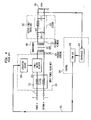
- FIG. 4 is a block diagram of a simplex power supply of a type well known in the prior art. This type of unit is discussed extensively, for example, in C. Y. Zhao et al.: "Secondary Side Synchronous Post Regulator Provides Precision Regulation And High Efficiency For Multiple Output Isolated Power Supplies", Linear Technology, vol. 12, no. 4, pp. 28-32, December 2002. Only those elements of the power supply necessary for understanding the architecture of Applicants' invention are shown.
- An input power train (101) connected to a source of power at its input and connected to a winding of a transformer at its output, is controlled by lead (131) from controller (130). The input power train provides energy to the primary winding (121) of transformer system (106).
- the amount of energy transferred from the input power train (101) to the output power train (102), is controlled by a pulse width modulation (PWM) signal from unit (118) within control (130); this signal via lead (131) drives an isolation device (116) such as a light emitting diode, a transformer, or a capacitor, which in turn controls a power switch element (115) that opens or closes a connection from filter (111) to primary winding (121) in response to the PWM control signal from controller (130).
- PWM pulse width modulation
- the output of transformer unit (106) is connected to an output power train (102) whose output is connected to the load (109) being powered by the power unit.
- the output winding (122) of the transformer is connected to a pair of rectifying diodes (104) and (105) whose outputs are connected to a filter (103) and thence to the load (109).
- the control unit (130), controlled by controller (119), provides feedback from the output of the output power train and the signal that is received from this output is used to modulate the PWM circuit (118) which as previously described controls the amount of energy supplied by the input driver to primary winding (121) and produces the desired output voltage at load (109).
- FIG. 5 is a block diagram illustrating Applicants' invention.
- a second input power train (210) similar to input power train (101) has been added.
- Input power train (210) is connected to a second primary winding of a transformer (225).
- Transformer (225) now has two primary windings (221) and (211) and one output winding (222).
- the control (220) now is required to control two separate input power trains, units (101) and (210). Consequently, control (220) has two PWM units (221) and (222) for driving these two input power trains.
- this overall arrangement isolates the two input power trains from each other, and from the output power train, and permits both input power trains, on a load sharing basis or individually, to drive the output power train (102).
- Control unit 220 is controlled by a programmed controller. When the power unit is initially turned on, it is necessary to bootstrap the control unit (220). This is accomplished with the help of a special source of power. This source is also highly reliable being supplied by duplicated low power units (260) and (262) whose outputs are fed to the control unit (220) over bootstrap power output (264). Bootstrap power output (264) permits a small amount of power to be sent to some additional loads on the board that need to operate even though the main output power train (102) is de-energized. This power is valuable for running small, continuous loads (265), for example, real-time clocks.
- the two low power units receive power from the two power distribution buses (201, 202) and (203, 204).
- the bootstrap arrangement allows the programmed controller to access the power control data link to receive instructions from a master controller (240) (discussed below). Each of the two bootstrap power units (260, 262) can supply enough power to drive control circuit (220).
- FIG. 6 illustrates that the programmed controller is connected to a power control data link (244) which permits the programmed controller to communicate with similar units also connected to the power control data link.
- Information exchanged between the programmed controllers can indicate the desirability of, for example, taking more power from the power distribution source supplying input power train (101).
- the power control data link can also communicate with a master controller (240) to convey information such as an alarm indication, indications that one or both power distribution sources have too high or too low a voltage, power outage, temperature, output current.
- a plurality of master controllers 240,...,242 are connected via another data link (252) to an office energy management controller (250) for overall control of the power system for an entire wirecenter.
- an alternative embodiment can use three (or more) input power trains and primary windings, for still higher reliability, especially if three or more main power distribution systems exist.
- the power control data link is an industry standard IIC bus.
- the output voltage is 12 volts and the acceptable input voltage is in the range of 36 to 72 volts.
Abstract
Description
- This invention relates to highly reliable power supplies and more specifically to highly reliable board mounted power modules.
- As a result of the increasing scale of integration which has been encountered during the past decades, a very large amount of circuitry can be mounted on a single circuit board. The amount of this circuitry is so great that every effort must be made to avoid a failure of a circuit board. As an example of a circuit board which contains a large body of critical circuitry, there is the case of a circuit board used as an interface for DS3 signals in a telecommunications network using digital (pulse code modulation) signals. This single board interfaces 672 voice channels. The loss of all these channels is, of course, highly undesirable.
- A major weak link in any such circuit board is the power supply. Typically, each such board has its own power supply driven from a single battery source.
- In the prior art, the most common arrangement for providing this highly reliable power is to have two separate power supplies and to simply parallel their outputs. If one power supply fails, power is still provided from the other supply. This is expensive in material cost and in board area. This arrangement has been used, for example, in the above-mentioned board for interfacing with DS3 signals in the No. 4ESS® formerly manufactured by Lucent Technologies Inc.
- To provide fault isolation, diodes may be inserted between the two power supplies and the load. A problem with this arrangement is that it is very difficult to detect diode failures, and it is therefore a source of potential problem if other failures occur. This particular problem has been solved in accordance with the teachings of U.S. Patent 6,157,308 which places the isolating diodes in close proximity to a controllable heater source and observing the voltage across the diode when the diode is heated.
- Another problem related to diodes is that the two power system's return currents can intermix, causing potential isolation issues which in turn can reduce system reliability.
- Both of the above arrangements are expensive and still have the disadvantage that problems in one of the duplicated power supplies cannot be fully isolated from the other power supply and can cause the board to fail.
- The above problems are essentially solved and an advance is made over the teachings of the prior art in accordance with this invention wherein redundancy is introduced into a single power supply by duplicating the input power train of one power supply and feeding each of the duplicated power trains to two separate primary windings of a three winding transformer. The secondary (or third winding) of the transformer is then connected to the output power train.
- Advantageously, this arrangement fully isolates the two input power trains of the power supply from each other (since they are connected to separate windings of the power transformer) and requires only a single output power train.
- Advantageously, this arrangement costs only about 30 percent more than a single power supply and is therefore much less expensive than a pair of power supplies provided for duplication and isolation purposes.
- Advantageously, redundancy is achieved without the use of diodes and at the same time the arrangement offers superb fault isolation capabilities.
- In accordance with Applicants' preferred embodiment, the power supply is controlled by a program controlled controller. This controller provides a pair of signals, one for each of the input power trains, to control the amount of energy that each input power train supplies to the primaries of the transformer. The controller can be arranged to have the power supply draw all input current from only one of the input power trains connected to one of the battery distribution systems. This is desirable if one of the input power sources fails or is removed from service for maintenance. In case a unit has been placed in the maintenance mode and there is a failure in the power system currently driving that unit, then the controller can automatically revert to a state in which the non-failing power distribution system is used.
- The controller can also be arranged to draw equal energy from each of the input power trains; this mode of operation increases the lifetime of the power supply since then under normal conditions, each single power supply is operating at 50% loading capacity. In equal energy mode, the current drawn from each power source is inversely proportional to its voltage. In a second mode - equal current, the two input power trains draw identical current from both sources, regardless of their voltage. An advantage with this mode is that currents are evenly distributed in the DC distribution system. Voltage transients are also minimized when the load current changes from two power sources to one.
- The controllers can also be used to detect alarm signals by detecting over- or under-voltage or current.
- In accordance with one preferred embodiment, a group of controllers are interconnected by a data link and are connected through that data link to a master controller (for controlling, for example, a shelf of circuit boards). Such master controllers, in turn, can be interconnected by another data link and connected to an office energy management controller for controlling an entire system.
- Advantageously, communications among the control circuits can be used for passing alarm signals or balancing the load between the two power distribution systems, across collections of multiple boards, shelves or frames, and to respond to maintenance requests.
- A problem of the type of power supplies illustrated in the preferred embodiment is that when a system or a board is started up, it is necessary to provide power to a board controller to bootstrap the main power system's controller and other small loads on the board. In accordance with Applicants' preferred embodiment this power supply is duplicated, each unit being connected to one of the two power distribution feeders. These power units, which typically supply only about 10 watts, have duplicated, isolated inputs and paralleled outputs, and are used to power the control unit.
-
- FIG. 1 is a simplified block diagram of a simplex unit of a type known in the prior art;
- FIG. 2 is a simplified block diagram of a duplex unit of the prior art;
- FIG. 3 is a simplified block diagram of a unit in accordance with Applicants' invention;
- FIG. 4 is a more detailed block diagram of a prior art simplex unit;
- FIG. 5 is a more detailed block diagram of a unit in accordance with Applicants' invention; and
- FIG. 6 is a block diagram illustrating interconnections among power units.
-
- FIG. 1 is a simplified diagram of a simplex prior art power system. Power is supplied from a first source (6, 7) and a second source (8, 9). The duplicated power feed protects against a failure of one of the power feed systems, and the isolation diodes (2, 3, 4, 5) prevent a failure of one of the power feed systems from affecting the other. The power module (1) is described in more detain in FIG. 4.
- FIG. 2 is a simplified diagram of a duplex prior art power supply using the same power module (1) as in FIG. 1. This arrangement protects against a failure of one of the power modules, as well as protecting against a failure of one of the power feed systems. It does not incur the problems associated with diodes, but does require paying the cost of two complete power modules.
- FIG. 3 is a simplified diagram of a power supply system using a new power module (10) in accordance with Applicants' invention. The new power module (10) is fed by both of the power supply feed systems, and uses a transformer to protect each of the power supply feed systems against a failure in the other.
- FIG. 4 is a block diagram of a simplex power supply of a type well known in the prior art. This type of unit is discussed extensively, for example, in C. Y. Zhao et al.: "Secondary Side Synchronous Post Regulator Provides Precision Regulation And High Efficiency For Multiple Output Isolated Power Supplies", Linear Technology, vol. 12, no. 4, pp. 28-32, December 2002. Only those elements of the power supply necessary for understanding the architecture of Applicants' invention are shown. An input power train (101) connected to a source of power at its input and connected to a winding of a transformer at its output, is controlled by lead (131) from controller (130). The input power train provides energy to the primary winding (121) of transformer system (106). The amount of energy transferred from the input power train (101) to the output power train (102), is controlled by a pulse width modulation (PWM) signal from unit (118) within control (130); this signal via lead (131) drives an isolation device (116) such as a light emitting diode, a transformer, or a capacitor, which in turn controls a power switch element (115) that opens or closes a connection from filter (111) to primary winding (121) in response to the PWM control signal from controller (130). The reason for using an isolation device (116) is to provide isolation between the control unit (130) and the power switch element (115) controlling the insertion of energy into primary winding (121).
- The output of transformer unit (106) is connected to an output power train (102) whose output is connected to the load (109) being powered by the power unit. The output winding (122) of the transformer is connected to a pair of rectifying diodes (104) and (105) whose outputs are connected to a filter (103) and thence to the load (109). The control unit (130), controlled by controller (119), provides feedback from the output of the output power train and the signal that is received from this output is used to modulate the PWM circuit (118) which as previously described controls the amount of energy supplied by the input driver to primary winding (121) and produces the desired output voltage at load (109).
- FIG. 5 is a block diagram illustrating Applicants' invention. In addition to input power train (101) and output power train (102), a second input power train (210) similar to input power train (101) has been added. Input power train (210) is connected to a second primary winding of a transformer (225). Transformer (225) now has two primary windings (221) and (211) and one output winding (222). The control (220) now is required to control two separate input power trains, units (101) and (210). Consequently, control (220) has two PWM units (221) and (222) for driving these two input power trains. Advantageously, this overall arrangement isolates the two input power trains from each other, and from the output power train, and permits both input power trains, on a load sharing basis or individually, to drive the output power train (102).
-
Control unit 220 is controlled by a programmed controller. When the power unit is initially turned on, it is necessary to bootstrap the control unit (220). This is accomplished with the help of a special source of power. This source is also highly reliable being supplied by duplicated low power units (260) and (262) whose outputs are fed to the control unit (220) over bootstrap power output (264). Bootstrap power output (264) permits a small amount of power to be sent to some additional loads on the board that need to operate even though the main output power train (102) is de-energized. This power is valuable for running small, continuous loads (265), for example, real-time clocks. The two low power units receive power from the two power distribution buses (201, 202) and (203, 204). The bootstrap arrangement allows the programmed controller to access the power control data link to receive instructions from a master controller (240) (discussed below). Each of the two bootstrap power units (260, 262) can supply enough power to drive control circuit (220). - FIG. 6 illustrates that the programmed controller is connected to a power control data link (244) which permits the programmed controller to communicate with similar units also connected to the power control data link. Information exchanged between the programmed controllers can indicate the desirability of, for example, taking more power from the power distribution source supplying input power train (101). The power control data link can also communicate with a master controller (240) to convey information such as an alarm indication, indications that one or both power distribution sources have too high or too low a voltage, power outage, temperature, output current. In addition, a plurality of
master controllers 240,...,242 are connected via another data link (252) to an office energy management controller (250) for overall control of the power system for an entire wirecenter. - While the preferred embodiment shows two input power trains and two primary windings, an alternative embodiment can use three (or more) input power trains and primary windings, for still higher reliability, especially if three or more main power distribution systems exist.
- In Applicants' preferred embodiment, the power control data link is an industry standard IIC bus. The output voltage is 12 volts and the acceptable input voltage is in the range of 36 to 72 volts.
- The above description is of one preferred embodiment of Applicants' invention. Other embodiments will be apparent to those of ordinary skill in the art without departing from the scope of the invention. The invention is limited only by the attached claims.
Claims (10)
- A highly reliable power supply unit comprising:a transformer having a first and a second primary winding and one secondary winding;a first power train unit connected to a first source of power, the output of said first power train unit being connected to said first primary winding of said transformer;a second power train unit connected to a second source of power, the output of said second power train unit being connected to said second primary winding of said transformer;an output power train unit connected to a secondary winding of said transformer, said output power train receiving an input from said secondary winding and converting said input into a reliable output power source.
- The apparatus of claim 1 further comprising a controller for controlling said first and said second power train units to supply energy to said first and said second primary winding.
- The apparatus of claim 2 wherein said controller operates under program control and is arranged to provide separate signals to said first and said second power train units and to vary an amount of energy supplied by said first and said second power train units.
- The apparatus of claim 2 further comprising a duplicated power supply for supplying power to said controller.
- The apparatus of claim 4 wherein said duplicated power supply for said controller supplies power for initial bootstrap operation when said reliable power supply is turned on.
- The apparatus of claim 2 wherein a control lead for controlling said first or said second power train unit is isolated from said controller supplying said control signal.
- The apparatus of claim 2 further comprising a data bus connected to said controller for communicating with controllers of other reliable power supply units.
- The apparatus of claim 2 further comprising a data bus connected to said controller for communicating with a master controller for controlling a plurality of controllers of reliable power supplies.
- The apparatus of claim 8 further comprising an office energy management controller for communicating with and for controlling a plurality of master controllers.
- The apparatus of claim 8 wherein said controller is used for detecting alarm conditions.
Applications Claiming Priority (2)
| Application Number | Priority Date | Filing Date | Title |
|---|---|---|---|
| US10/400,012 US6774507B1 (en) | 2003-03-26 | 2003-03-26 | Reliable DC power supply |
| US400012 | 2003-03-26 |
Publications (1)
| Publication Number | Publication Date |
|---|---|
| EP1463190A1 true EP1463190A1 (en) | 2004-09-29 |
Family
ID=32824984
Family Applications (1)
| Application Number | Title | Priority Date | Filing Date |
|---|---|---|---|
| EP20040250978 Ceased EP1463190A1 (en) | 2003-03-26 | 2004-02-24 | Reliable board mounted power module |
Country Status (7)
| Country | Link |
|---|---|
| US (1) | US6774507B1 (en) |
| EP (1) | EP1463190A1 (en) |
| JP (1) | JP4676153B2 (en) |
| KR (1) | KR101125685B1 (en) |
| CN (1) | CN1538806B (en) |
| BR (1) | BRPI0400318A (en) |
| MX (1) | MXPA04002691A (en) |
Cited By (2)
| Publication number | Priority date | Publication date | Assignee | Title |
|---|---|---|---|---|
| WO2007055998A2 (en) * | 2005-11-08 | 2007-05-18 | Eveready Battery Company, Inc. | Enhanced portable battery powered electrical appliance |
| WO2008151859A1 (en) * | 2007-06-14 | 2008-12-18 | Siemens Aktiengesellschaft | Inverter compound with an intermediate circuit transmitting energy and communication data |
Families Citing this family (8)
| Publication number | Priority date | Publication date | Assignee | Title |
|---|---|---|---|---|
| JP2006280179A (en) * | 2005-03-30 | 2006-10-12 | Honda Motor Co Ltd | Dc-stabilizing power supply |
| US8212401B2 (en) * | 2007-08-03 | 2012-07-03 | Stratascale, Inc. | Redundant isolation and bypass of critical power equipment |
| US8294297B2 (en) * | 2007-08-03 | 2012-10-23 | Ragingwire Enterprise Solutions, Inc. | Scalable distributed redundancy |
| JP5800427B2 (en) | 2011-12-28 | 2015-10-28 | 三菱日立パワーシステムズ株式会社 | Power supply apparatus and power supply switching method |
| US9509222B2 (en) * | 2012-05-04 | 2016-11-29 | Control Techniques Limited | Power conversion system |
| GB2501773A (en) * | 2012-05-04 | 2013-11-06 | Control Tech Ltd | Dual primary switch mode power supply having individual primary control |
| CN104377688A (en) * | 2014-11-12 | 2015-02-25 | 南车株洲电力机车研究所有限公司 | Power control system and train control device |
| CN106882084B (en) * | 2017-03-20 | 2023-09-22 | 中铁二院工程集团有限责任公司 | Main wiring structure of high-speed rail transformer station based on three single-phase traction transformers |
Citations (9)
| Publication number | Priority date | Publication date | Assignee | Title |
|---|---|---|---|---|
| US3398292A (en) * | 1965-07-19 | 1968-08-20 | North Electric Co | Current supply apparatus |
| US5459652A (en) * | 1994-01-28 | 1995-10-17 | Compaq Computer Corp. | Boot strap circuit for power up control of power supplies |
| US5483463A (en) * | 1993-07-30 | 1996-01-09 | Controlled Power Company | Uninterruptible power supply (UPS) and method |
| US5708579A (en) * | 1996-05-02 | 1998-01-13 | Chrysler Corporation | Gate driver supply |
| US5751564A (en) * | 1994-08-10 | 1998-05-12 | Dien; Ghing-Hsin | Dual/multiple voltage level input switching power supply |
| US6157308A (en) * | 1999-06-10 | 2000-12-05 | Lucent Technologies Inc. | Detecting hidden faults in reliable power systems |
| US6275958B1 (en) * | 1998-10-28 | 2001-08-14 | International Business Machines Corporation | Fault detection in a redundant power converter |
| US20030033463A1 (en) * | 2001-08-10 | 2003-02-13 | Garnett Paul J. | Computer system storage |
| US6650028B1 (en) * | 2001-11-27 | 2003-11-18 | Verilink, Inc. | Dual isolated input power supply |
Family Cites Families (4)
| Publication number | Priority date | Publication date | Assignee | Title |
|---|---|---|---|---|
| US5657214A (en) * | 1991-06-03 | 1997-08-12 | Sundstrand Corporation | Stepped waveform PWM inverter |
| JP3008081B2 (en) * | 1996-03-18 | 2000-02-14 | 株式会社日本プロテクター | Uninterruptible switching regulator |
| US6198178B1 (en) * | 1999-12-21 | 2001-03-06 | International Power Systems, Inc. | Step wave power converter |
| JP2002152993A (en) * | 2000-11-14 | 2002-05-24 | Toshiba Battery Co Ltd | Uninterruptible power supply |
-
2003
- 2003-03-26 US US10/400,012 patent/US6774507B1/en not_active Expired - Lifetime
-
2004
- 2004-02-24 EP EP20040250978 patent/EP1463190A1/en not_active Ceased
- 2004-03-19 BR BRPI0400318 patent/BRPI0400318A/en not_active Application Discontinuation
- 2004-03-19 KR KR1020040018945A patent/KR101125685B1/en active IP Right Grant
- 2004-03-22 MX MXPA04002691A patent/MXPA04002691A/en unknown
- 2004-03-23 CN CN2004100302667A patent/CN1538806B/en not_active Expired - Fee Related
- 2004-03-26 JP JP2004092388A patent/JP4676153B2/en not_active Expired - Fee Related
Patent Citations (9)
| Publication number | Priority date | Publication date | Assignee | Title |
|---|---|---|---|---|
| US3398292A (en) * | 1965-07-19 | 1968-08-20 | North Electric Co | Current supply apparatus |
| US5483463A (en) * | 1993-07-30 | 1996-01-09 | Controlled Power Company | Uninterruptible power supply (UPS) and method |
| US5459652A (en) * | 1994-01-28 | 1995-10-17 | Compaq Computer Corp. | Boot strap circuit for power up control of power supplies |
| US5751564A (en) * | 1994-08-10 | 1998-05-12 | Dien; Ghing-Hsin | Dual/multiple voltage level input switching power supply |
| US5708579A (en) * | 1996-05-02 | 1998-01-13 | Chrysler Corporation | Gate driver supply |
| US6275958B1 (en) * | 1998-10-28 | 2001-08-14 | International Business Machines Corporation | Fault detection in a redundant power converter |
| US6157308A (en) * | 1999-06-10 | 2000-12-05 | Lucent Technologies Inc. | Detecting hidden faults in reliable power systems |
| US20030033463A1 (en) * | 2001-08-10 | 2003-02-13 | Garnett Paul J. | Computer system storage |
| US6650028B1 (en) * | 2001-11-27 | 2003-11-18 | Verilink, Inc. | Dual isolated input power supply |
Non-Patent Citations (1)
| Title |
|---|
| YAOW-MING CHEN; YUAN-CHUAN LIU; FENG-YU WU: "Multi-Input DC/DC Converter Based on the Multiwinding Transformer for Renewable Energy Applications", IEEE TRANSACTIONS ON INDUSTRY APPLICATIONS, IEEE SERVICE CENTER, PISCATAWAY, NJ, US, vol. 38, no. 4, July 2002 (2002-07-01), pages 1096 - 1104, XP011073486 * |
Cited By (6)
| Publication number | Priority date | Publication date | Assignee | Title |
|---|---|---|---|---|
| WO2007055998A2 (en) * | 2005-11-08 | 2007-05-18 | Eveready Battery Company, Inc. | Enhanced portable battery powered electrical appliance |
| WO2007055998A3 (en) * | 2005-11-08 | 2007-12-21 | Eveready Battery Inc | Enhanced portable battery powered electrical appliance |
| US7688029B2 (en) | 2005-11-08 | 2010-03-30 | Eveready Battery Company, Inc. | Portable battery powered appliance and method of operation |
| US8044634B2 (en) | 2005-11-08 | 2011-10-25 | Eveready Battery Company, Inc. | Enhanced portable battery powered electrical appliance |
| US8648567B2 (en) | 2005-11-08 | 2014-02-11 | Eveready Battery Co., Inc. | Enhanced portable battery powered electrical appliance |
| WO2008151859A1 (en) * | 2007-06-14 | 2008-12-18 | Siemens Aktiengesellschaft | Inverter compound with an intermediate circuit transmitting energy and communication data |
Also Published As
| Publication number | Publication date |
|---|---|
| CN1538806B (en) | 2010-06-16 |
| JP2004295892A (en) | 2004-10-21 |
| BRPI0400318A (en) | 2005-05-24 |
| KR101125685B1 (en) | 2012-03-27 |
| MXPA04002691A (en) | 2005-08-26 |
| KR20040084672A (en) | 2004-10-06 |
| US6774507B1 (en) | 2004-08-10 |
| CN1538806A (en) | 2004-10-20 |
| JP4676153B2 (en) | 2011-04-27 |
Similar Documents
| Publication | Publication Date | Title |
|---|---|---|
| US6850048B2 (en) | Power supply controller | |
| US10003200B2 (en) | Decentralized module-based DC data center | |
| CA2771838C (en) | Emergency power supply apparatus | |
| EP1833138B1 (en) | Nested redundant uninterruptible power supply apparatus and methods | |
| US4400792A (en) | Dual-channel data processing system for railroad safety purposes | |
| EP0243061B1 (en) | Off-line switcher with battery reserve | |
| US4607330A (en) | Fault-tolerant power supply system | |
| US7266709B2 (en) | Method and system for controlling an array of point-of-load regulators and auxiliary devices | |
| US6774507B1 (en) | Reliable DC power supply | |
| US20040010649A1 (en) | User-configurable power architecture with hot-pluggable power modules | |
| KR101971242B1 (en) | Power supply | |
| US5790394A (en) | Dual AC power supply input module | |
| US7999410B2 (en) | System for high reliability power distribution within an electronics equipment cabinet | |
| EP1990892B1 (en) | Battery discharge current sharing in a tightly regulated power system | |
| AU2012312714B2 (en) | Parallel control and protection for UPS | |
| KR100321976B1 (en) | Fault tolerant voltage regulator module circuit for intel processors | |
| US6630750B2 (en) | Spare bus power plant | |
| EP3262735B1 (en) | Emergency supply unit | |
| US20030168913A1 (en) | Power system with load matrix | |
| US8154887B2 (en) | Dual isolated input single power supply topology | |
| KR100644335B1 (en) | A uninterruptible power supply of the mode of the dual | |
| US6650028B1 (en) | Dual isolated input power supply | |
| US20070176493A1 (en) | Method and system for powering a patient monitoring system | |
| KR20030054643A (en) | Control apparatus for supply power in double power supply system | |
| CN218783622U (en) | Power supply apparatus and power supply system |
Legal Events
| Date | Code | Title | Description |
|---|---|---|---|
| PUAI | Public reference made under article 153(3) epc to a published international application that has entered the european phase |
Free format text: ORIGINAL CODE: 0009012 |
|
| 17P | Request for examination filed |
Effective date: 20040306 |
|
| AK | Designated contracting states |
Kind code of ref document: A1 Designated state(s): AT BE BG CH CY CZ DE DK EE ES FI FR GB GR HU IE IT LI LU MC NL PT RO SE SI SK TR |
|
| AX | Request for extension of the european patent |
Extension state: AL LT LV MK |
|
| 17Q | First examination report despatched |
Effective date: 20050112 |
|
| AKX | Designation fees paid |
Designated state(s): AT BE BG CH CY CZ DE DK EE ES FI FR GB GR HU IE IT LI LU MC NL PT RO SE SI SK TR |
|
| 17Q | First examination report despatched |
Effective date: 20050112 |
|
| APBK | Appeal reference recorded |
Free format text: ORIGINAL CODE: EPIDOSNREFNE |
|
| APBN | Date of receipt of notice of appeal recorded |
Free format text: ORIGINAL CODE: EPIDOSNNOA2E |
|
| APBR | Date of receipt of statement of grounds of appeal recorded |
Free format text: ORIGINAL CODE: EPIDOSNNOA3E |
|
| APAF | Appeal reference modified |
Free format text: ORIGINAL CODE: EPIDOSCREFNE |
|
| APAF | Appeal reference modified |
Free format text: ORIGINAL CODE: EPIDOSCREFNE |
|
| RAP3 | Party data changed (applicant data changed or rights of an application transferred) |
Owner name: LUCENT TECHNOLOGIES INC. |
|
| APBT | Appeal procedure closed |
Free format text: ORIGINAL CODE: EPIDOSNNOA9E |
|
| STAA | Information on the status of an ep patent application or granted ep patent |
Free format text: STATUS: THE APPLICATION HAS BEEN REFUSED |
|
| 18R | Application refused |
Effective date: 20120124 |