EP1457496A1 - high density immobilization of nucleic acids - Google Patents
high density immobilization of nucleic acids Download PDFInfo
- Publication number
- EP1457496A1 EP1457496A1 EP04075083A EP04075083A EP1457496A1 EP 1457496 A1 EP1457496 A1 EP 1457496A1 EP 04075083 A EP04075083 A EP 04075083A EP 04075083 A EP04075083 A EP 04075083A EP 1457496 A1 EP1457496 A1 EP 1457496A1
- Authority
- EP
- European Patent Office
- Prior art keywords
- fluid
- housing
- dispensing
- vesicles
- interior volume
- Prior art date
- Legal status (The legal status is an assumption and is not a legal conclusion. Google has not performed a legal analysis and makes no representation as to the accuracy of the status listed.)
- Granted
Links
- 0 *C(c1cc(O)c(*)cc1[N+]([O-])=O)O* Chemical compound *C(c1cc(O)c(*)cc1[N+]([O-])=O)O* 0.000 description 3
Images


Classifications
-
- B—PERFORMING OPERATIONS; TRANSPORTING
- B01—PHYSICAL OR CHEMICAL PROCESSES OR APPARATUS IN GENERAL
- B01L—CHEMICAL OR PHYSICAL LABORATORY APPARATUS FOR GENERAL USE
- B01L3/00—Containers or dishes for laboratory use, e.g. laboratory glassware; Droppers
- B01L3/02—Burettes; Pipettes
- B01L3/0241—Drop counters; Drop formers
- B01L3/0244—Drop counters; Drop formers using pins
-
- B—PERFORMING OPERATIONS; TRANSPORTING
- B01—PHYSICAL OR CHEMICAL PROCESSES OR APPARATUS IN GENERAL
- B01J—CHEMICAL OR PHYSICAL PROCESSES, e.g. CATALYSIS OR COLLOID CHEMISTRY; THEIR RELEVANT APPARATUS
- B01J19/00—Chemical, physical or physico-chemical processes in general; Their relevant apparatus
- B01J19/0046—Sequential or parallel reactions, e.g. for the synthesis of polypeptides or polynucleotides; Apparatus and devices for combinatorial chemistry or for making molecular arrays
-
- B—PERFORMING OPERATIONS; TRANSPORTING
- B01—PHYSICAL OR CHEMICAL PROCESSES OR APPARATUS IN GENERAL
- B01L—CHEMICAL OR PHYSICAL LABORATORY APPARATUS FOR GENERAL USE
- B01L3/00—Containers or dishes for laboratory use, e.g. laboratory glassware; Droppers
- B01L3/02—Burettes; Pipettes
- B01L3/0241—Drop counters; Drop formers
- B01L3/0262—Drop counters; Drop formers using touch-off at substrate or container
-
- B—PERFORMING OPERATIONS; TRANSPORTING
- B01—PHYSICAL OR CHEMICAL PROCESSES OR APPARATUS IN GENERAL
- B01L—CHEMICAL OR PHYSICAL LABORATORY APPARATUS FOR GENERAL USE
- B01L3/00—Containers or dishes for laboratory use, e.g. laboratory glassware; Droppers
- B01L3/02—Burettes; Pipettes
- B01L3/0241—Drop counters; Drop formers
- B01L3/0268—Drop counters; Drop formers using pulse dispensing or spraying, eg. inkjet type, piezo actuated ejection of droplets from capillaries
-
- C—CHEMISTRY; METALLURGY
- C07—ORGANIC CHEMISTRY
- C07F—ACYCLIC, CARBOCYCLIC OR HETEROCYCLIC COMPOUNDS CONTAINING ELEMENTS OTHER THAN CARBON, HYDROGEN, HALOGEN, OXYGEN, NITROGEN, SULFUR, SELENIUM OR TELLURIUM
- C07F9/00—Compounds containing elements of Groups 5 or 15 of the Periodic System
- C07F9/02—Phosphorus compounds
- C07F9/06—Phosphorus compounds without P—C bonds
- C07F9/22—Amides of acids of phosphorus
- C07F9/24—Esteramides
- C07F9/2404—Esteramides the ester moiety containing a substituent or a structure which is considered as characteristic
- C07F9/2408—Esteramides the ester moiety containing a substituent or a structure which is considered as characteristic of hydroxyalkyl compounds
-
- C—CHEMISTRY; METALLURGY
- C07—ORGANIC CHEMISTRY
- C07F—ACYCLIC, CARBOCYCLIC OR HETEROCYCLIC COMPOUNDS CONTAINING ELEMENTS OTHER THAN CARBON, HYDROGEN, HALOGEN, OXYGEN, NITROGEN, SULFUR, SELENIUM OR TELLURIUM
- C07F9/00—Compounds containing elements of Groups 5 or 15 of the Periodic System
- C07F9/02—Phosphorus compounds
- C07F9/06—Phosphorus compounds without P—C bonds
- C07F9/22—Amides of acids of phosphorus
- C07F9/24—Esteramides
- C07F9/2404—Esteramides the ester moiety containing a substituent or a structure which is considered as characteristic
- C07F9/2429—Esteramides the ester moiety containing a substituent or a structure which is considered as characteristic of arylalkanols
-
- C—CHEMISTRY; METALLURGY
- C07—ORGANIC CHEMISTRY
- C07H—SUGARS; DERIVATIVES THEREOF; NUCLEOSIDES; NUCLEOTIDES; NUCLEIC ACIDS
- C07H21/00—Compounds containing two or more mononucleotide units having separate phosphate or polyphosphate groups linked by saccharide radicals of nucleoside groups, e.g. nucleic acids
-
- C—CHEMISTRY; METALLURGY
- C12—BIOCHEMISTRY; BEER; SPIRITS; WINE; VINEGAR; MICROBIOLOGY; ENZYMOLOGY; MUTATION OR GENETIC ENGINEERING
- C12Q—MEASURING OR TESTING PROCESSES INVOLVING ENZYMES, NUCLEIC ACIDS OR MICROORGANISMS; COMPOSITIONS OR TEST PAPERS THEREFOR; PROCESSES OF PREPARING SUCH COMPOSITIONS; CONDITION-RESPONSIVE CONTROL IN MICROBIOLOGICAL OR ENZYMOLOGICAL PROCESSES
- C12Q1/00—Measuring or testing processes involving enzymes, nucleic acids or microorganisms; Compositions therefor; Processes of preparing such compositions
- C12Q1/68—Measuring or testing processes involving enzymes, nucleic acids or microorganisms; Compositions therefor; Processes of preparing such compositions involving nucleic acids
- C12Q1/6813—Hybridisation assays
- C12Q1/6816—Hybridisation assays characterised by the detection means
-
- C—CHEMISTRY; METALLURGY
- C12—BIOCHEMISTRY; BEER; SPIRITS; WINE; VINEGAR; MICROBIOLOGY; ENZYMOLOGY; MUTATION OR GENETIC ENGINEERING
- C12Q—MEASURING OR TESTING PROCESSES INVOLVING ENZYMES, NUCLEIC ACIDS OR MICROORGANISMS; COMPOSITIONS OR TEST PAPERS THEREFOR; PROCESSES OF PREPARING SUCH COMPOSITIONS; CONDITION-RESPONSIVE CONTROL IN MICROBIOLOGICAL OR ENZYMOLOGICAL PROCESSES
- C12Q1/00—Measuring or testing processes involving enzymes, nucleic acids or microorganisms; Compositions therefor; Processes of preparing such compositions
- C12Q1/68—Measuring or testing processes involving enzymes, nucleic acids or microorganisms; Compositions therefor; Processes of preparing such compositions involving nucleic acids
- C12Q1/6813—Hybridisation assays
- C12Q1/6827—Hybridisation assays for detection of mutation or polymorphism
-
- C—CHEMISTRY; METALLURGY
- C12—BIOCHEMISTRY; BEER; SPIRITS; WINE; VINEGAR; MICROBIOLOGY; ENZYMOLOGY; MUTATION OR GENETIC ENGINEERING
- C12Q—MEASURING OR TESTING PROCESSES INVOLVING ENZYMES, NUCLEIC ACIDS OR MICROORGANISMS; COMPOSITIONS OR TEST PAPERS THEREFOR; PROCESSES OF PREPARING SUCH COMPOSITIONS; CONDITION-RESPONSIVE CONTROL IN MICROBIOLOGICAL OR ENZYMOLOGICAL PROCESSES
- C12Q1/00—Measuring or testing processes involving enzymes, nucleic acids or microorganisms; Compositions therefor; Processes of preparing such compositions
- C12Q1/68—Measuring or testing processes involving enzymes, nucleic acids or microorganisms; Compositions therefor; Processes of preparing such compositions involving nucleic acids
- C12Q1/6813—Hybridisation assays
- C12Q1/6834—Enzymatic or biochemical coupling of nucleic acids to a solid phase
- C12Q1/6837—Enzymatic or biochemical coupling of nucleic acids to a solid phase using probe arrays or probe chips
-
- C—CHEMISTRY; METALLURGY
- C12—BIOCHEMISTRY; BEER; SPIRITS; WINE; VINEGAR; MICROBIOLOGY; ENZYMOLOGY; MUTATION OR GENETIC ENGINEERING
- C12Q—MEASURING OR TESTING PROCESSES INVOLVING ENZYMES, NUCLEIC ACIDS OR MICROORGANISMS; COMPOSITIONS OR TEST PAPERS THEREFOR; PROCESSES OF PREPARING SUCH COMPOSITIONS; CONDITION-RESPONSIVE CONTROL IN MICROBIOLOGICAL OR ENZYMOLOGICAL PROCESSES
- C12Q1/00—Measuring or testing processes involving enzymes, nucleic acids or microorganisms; Compositions therefor; Processes of preparing such compositions
- C12Q1/68—Measuring or testing processes involving enzymes, nucleic acids or microorganisms; Compositions therefor; Processes of preparing such compositions involving nucleic acids
- C12Q1/6844—Nucleic acid amplification reactions
- C12Q1/6858—Allele-specific amplification
-
- C—CHEMISTRY; METALLURGY
- C12—BIOCHEMISTRY; BEER; SPIRITS; WINE; VINEGAR; MICROBIOLOGY; ENZYMOLOGY; MUTATION OR GENETIC ENGINEERING
- C12Q—MEASURING OR TESTING PROCESSES INVOLVING ENZYMES, NUCLEIC ACIDS OR MICROORGANISMS; COMPOSITIONS OR TEST PAPERS THEREFOR; PROCESSES OF PREPARING SUCH COMPOSITIONS; CONDITION-RESPONSIVE CONTROL IN MICROBIOLOGICAL OR ENZYMOLOGICAL PROCESSES
- C12Q1/00—Measuring or testing processes involving enzymes, nucleic acids or microorganisms; Compositions therefor; Processes of preparing such compositions
- C12Q1/68—Measuring or testing processes involving enzymes, nucleic acids or microorganisms; Compositions therefor; Processes of preparing such compositions involving nucleic acids
- C12Q1/6869—Methods for sequencing
- C12Q1/6872—Methods for sequencing involving mass spectrometry
-
- C—CHEMISTRY; METALLURGY
- C12—BIOCHEMISTRY; BEER; SPIRITS; WINE; VINEGAR; MICROBIOLOGY; ENZYMOLOGY; MUTATION OR GENETIC ENGINEERING
- C12Q—MEASURING OR TESTING PROCESSES INVOLVING ENZYMES, NUCLEIC ACIDS OR MICROORGANISMS; COMPOSITIONS OR TEST PAPERS THEREFOR; PROCESSES OF PREPARING SUCH COMPOSITIONS; CONDITION-RESPONSIVE CONTROL IN MICROBIOLOGICAL OR ENZYMOLOGICAL PROCESSES
- C12Q1/00—Measuring or testing processes involving enzymes, nucleic acids or microorganisms; Compositions therefor; Processes of preparing such compositions
- C12Q1/68—Measuring or testing processes involving enzymes, nucleic acids or microorganisms; Compositions therefor; Processes of preparing such compositions involving nucleic acids
- C12Q1/6876—Nucleic acid products used in the analysis of nucleic acids, e.g. primers or probes
- C12Q1/6883—Nucleic acid products used in the analysis of nucleic acids, e.g. primers or probes for diseases caused by alterations of genetic material
- C12Q1/6886—Nucleic acid products used in the analysis of nucleic acids, e.g. primers or probes for diseases caused by alterations of genetic material for cancer
-
- G—PHYSICS
- G01—MEASURING; TESTING
- G01N—INVESTIGATING OR ANALYSING MATERIALS BY DETERMINING THEIR CHEMICAL OR PHYSICAL PROPERTIES
- G01N35/00—Automatic analysis not limited to methods or materials provided for in any single one of groups G01N1/00 - G01N33/00; Handling materials therefor
- G01N35/10—Devices for transferring samples or any liquids to, in, or from, the analysis apparatus, e.g. suction devices, injection devices
- G01N35/1065—Multiple transfer devices
- G01N35/1067—Multiple transfer devices for transfer to or from containers having different spacing
-
- B—PERFORMING OPERATIONS; TRANSPORTING
- B01—PHYSICAL OR CHEMICAL PROCESSES OR APPARATUS IN GENERAL
- B01J—CHEMICAL OR PHYSICAL PROCESSES, e.g. CATALYSIS OR COLLOID CHEMISTRY; THEIR RELEVANT APPARATUS
- B01J2219/00—Chemical, physical or physico-chemical processes in general; Their relevant apparatus
- B01J2219/00274—Sequential or parallel reactions; Apparatus and devices for combinatorial chemistry or for making arrays; Chemical library technology
- B01J2219/00277—Apparatus
- B01J2219/00279—Features relating to reactor vessels
- B01J2219/00306—Reactor vessels in a multiple arrangement
- B01J2219/00313—Reactor vessels in a multiple arrangement the reactor vessels being formed by arrays of wells in blocks
- B01J2219/00315—Microtiter plates
- B01J2219/00317—Microwell devices, i.e. having large numbers of wells
-
- B—PERFORMING OPERATIONS; TRANSPORTING
- B01—PHYSICAL OR CHEMICAL PROCESSES OR APPARATUS IN GENERAL
- B01J—CHEMICAL OR PHYSICAL PROCESSES, e.g. CATALYSIS OR COLLOID CHEMISTRY; THEIR RELEVANT APPARATUS
- B01J2219/00—Chemical, physical or physico-chemical processes in general; Their relevant apparatus
- B01J2219/00274—Sequential or parallel reactions; Apparatus and devices for combinatorial chemistry or for making arrays; Chemical library technology
- B01J2219/00277—Apparatus
- B01J2219/00351—Means for dispensing and evacuation of reagents
- B01J2219/00387—Applications using probes
-
- B—PERFORMING OPERATIONS; TRANSPORTING
- B01—PHYSICAL OR CHEMICAL PROCESSES OR APPARATUS IN GENERAL
- B01J—CHEMICAL OR PHYSICAL PROCESSES, e.g. CATALYSIS OR COLLOID CHEMISTRY; THEIR RELEVANT APPARATUS
- B01J2219/00—Chemical, physical or physico-chemical processes in general; Their relevant apparatus
- B01J2219/00274—Sequential or parallel reactions; Apparatus and devices for combinatorial chemistry or for making arrays; Chemical library technology
- B01J2219/00277—Apparatus
- B01J2219/00457—Dispensing or evacuation of the solid phase support
- B01J2219/00459—Beads
- B01J2219/00468—Beads by manipulation of individual beads
-
- B—PERFORMING OPERATIONS; TRANSPORTING
- B01—PHYSICAL OR CHEMICAL PROCESSES OR APPARATUS IN GENERAL
- B01J—CHEMICAL OR PHYSICAL PROCESSES, e.g. CATALYSIS OR COLLOID CHEMISTRY; THEIR RELEVANT APPARATUS
- B01J2219/00—Chemical, physical or physico-chemical processes in general; Their relevant apparatus
- B01J2219/00274—Sequential or parallel reactions; Apparatus and devices for combinatorial chemistry or for making arrays; Chemical library technology
- B01J2219/00277—Apparatus
- B01J2219/00497—Features relating to the solid phase supports
- B01J2219/005—Beads
-
- B—PERFORMING OPERATIONS; TRANSPORTING
- B01—PHYSICAL OR CHEMICAL PROCESSES OR APPARATUS IN GENERAL
- B01J—CHEMICAL OR PHYSICAL PROCESSES, e.g. CATALYSIS OR COLLOID CHEMISTRY; THEIR RELEVANT APPARATUS
- B01J2219/00—Chemical, physical or physico-chemical processes in general; Their relevant apparatus
- B01J2219/00274—Sequential or parallel reactions; Apparatus and devices for combinatorial chemistry or for making arrays; Chemical library technology
- B01J2219/00277—Apparatus
- B01J2219/00497—Features relating to the solid phase supports
- B01J2219/00504—Pins
-
- B—PERFORMING OPERATIONS; TRANSPORTING
- B01—PHYSICAL OR CHEMICAL PROCESSES OR APPARATUS IN GENERAL
- B01J—CHEMICAL OR PHYSICAL PROCESSES, e.g. CATALYSIS OR COLLOID CHEMISTRY; THEIR RELEVANT APPARATUS
- B01J2219/00—Chemical, physical or physico-chemical processes in general; Their relevant apparatus
- B01J2219/00274—Sequential or parallel reactions; Apparatus and devices for combinatorial chemistry or for making arrays; Chemical library technology
- B01J2219/00277—Apparatus
- B01J2219/00497—Features relating to the solid phase supports
- B01J2219/00511—Walls of reactor vessels
-
- B—PERFORMING OPERATIONS; TRANSPORTING
- B01—PHYSICAL OR CHEMICAL PROCESSES OR APPARATUS IN GENERAL
- B01J—CHEMICAL OR PHYSICAL PROCESSES, e.g. CATALYSIS OR COLLOID CHEMISTRY; THEIR RELEVANT APPARATUS
- B01J2219/00—Chemical, physical or physico-chemical processes in general; Their relevant apparatus
- B01J2219/00274—Sequential or parallel reactions; Apparatus and devices for combinatorial chemistry or for making arrays; Chemical library technology
- B01J2219/00277—Apparatus
- B01J2219/00497—Features relating to the solid phase supports
- B01J2219/00513—Essentially linear supports
- B01J2219/0052—Essentially linear supports in the shape of elongated tubes
-
- B—PERFORMING OPERATIONS; TRANSPORTING
- B01—PHYSICAL OR CHEMICAL PROCESSES OR APPARATUS IN GENERAL
- B01J—CHEMICAL OR PHYSICAL PROCESSES, e.g. CATALYSIS OR COLLOID CHEMISTRY; THEIR RELEVANT APPARATUS
- B01J2219/00—Chemical, physical or physico-chemical processes in general; Their relevant apparatus
- B01J2219/00274—Sequential or parallel reactions; Apparatus and devices for combinatorial chemistry or for making arrays; Chemical library technology
- B01J2219/00277—Apparatus
- B01J2219/00497—Features relating to the solid phase supports
- B01J2219/00527—Sheets
-
- B—PERFORMING OPERATIONS; TRANSPORTING
- B01—PHYSICAL OR CHEMICAL PROCESSES OR APPARATUS IN GENERAL
- B01J—CHEMICAL OR PHYSICAL PROCESSES, e.g. CATALYSIS OR COLLOID CHEMISTRY; THEIR RELEVANT APPARATUS
- B01J2219/00—Chemical, physical or physico-chemical processes in general; Their relevant apparatus
- B01J2219/00274—Sequential or parallel reactions; Apparatus and devices for combinatorial chemistry or for making arrays; Chemical library technology
- B01J2219/00583—Features relative to the processes being carried out
- B01J2219/00585—Parallel processes
-
- B—PERFORMING OPERATIONS; TRANSPORTING
- B01—PHYSICAL OR CHEMICAL PROCESSES OR APPARATUS IN GENERAL
- B01J—CHEMICAL OR PHYSICAL PROCESSES, e.g. CATALYSIS OR COLLOID CHEMISTRY; THEIR RELEVANT APPARATUS
- B01J2219/00—Chemical, physical or physico-chemical processes in general; Their relevant apparatus
- B01J2219/00274—Sequential or parallel reactions; Apparatus and devices for combinatorial chemistry or for making arrays; Chemical library technology
- B01J2219/00583—Features relative to the processes being carried out
- B01J2219/00596—Solid-phase processes
-
- B—PERFORMING OPERATIONS; TRANSPORTING
- B01—PHYSICAL OR CHEMICAL PROCESSES OR APPARATUS IN GENERAL
- B01J—CHEMICAL OR PHYSICAL PROCESSES, e.g. CATALYSIS OR COLLOID CHEMISTRY; THEIR RELEVANT APPARATUS
- B01J2219/00—Chemical, physical or physico-chemical processes in general; Their relevant apparatus
- B01J2219/00274—Sequential or parallel reactions; Apparatus and devices for combinatorial chemistry or for making arrays; Chemical library technology
- B01J2219/00583—Features relative to the processes being carried out
- B01J2219/00603—Making arrays on substantially continuous surfaces
- B01J2219/00605—Making arrays on substantially continuous surfaces the compounds being directly bound or immobilised to solid supports
- B01J2219/0061—The surface being organic
-
- B—PERFORMING OPERATIONS; TRANSPORTING
- B01—PHYSICAL OR CHEMICAL PROCESSES OR APPARATUS IN GENERAL
- B01J—CHEMICAL OR PHYSICAL PROCESSES, e.g. CATALYSIS OR COLLOID CHEMISTRY; THEIR RELEVANT APPARATUS
- B01J2219/00—Chemical, physical or physico-chemical processes in general; Their relevant apparatus
- B01J2219/00274—Sequential or parallel reactions; Apparatus and devices for combinatorial chemistry or for making arrays; Chemical library technology
- B01J2219/00583—Features relative to the processes being carried out
- B01J2219/00603—Making arrays on substantially continuous surfaces
- B01J2219/00605—Making arrays on substantially continuous surfaces the compounds being directly bound or immobilised to solid supports
- B01J2219/00612—Making arrays on substantially continuous surfaces the compounds being directly bound or immobilised to solid supports the surface being inorganic
-
- B—PERFORMING OPERATIONS; TRANSPORTING
- B01—PHYSICAL OR CHEMICAL PROCESSES OR APPARATUS IN GENERAL
- B01J—CHEMICAL OR PHYSICAL PROCESSES, e.g. CATALYSIS OR COLLOID CHEMISTRY; THEIR RELEVANT APPARATUS
- B01J2219/00—Chemical, physical or physico-chemical processes in general; Their relevant apparatus
- B01J2219/00274—Sequential or parallel reactions; Apparatus and devices for combinatorial chemistry or for making arrays; Chemical library technology
- B01J2219/00583—Features relative to the processes being carried out
- B01J2219/00603—Making arrays on substantially continuous surfaces
- B01J2219/00605—Making arrays on substantially continuous surfaces the compounds being directly bound or immobilised to solid supports
- B01J2219/00614—Delimitation of the attachment areas
- B01J2219/00621—Delimitation of the attachment areas by physical means, e.g. trenches, raised areas
-
- B—PERFORMING OPERATIONS; TRANSPORTING
- B01—PHYSICAL OR CHEMICAL PROCESSES OR APPARATUS IN GENERAL
- B01J—CHEMICAL OR PHYSICAL PROCESSES, e.g. CATALYSIS OR COLLOID CHEMISTRY; THEIR RELEVANT APPARATUS
- B01J2219/00—Chemical, physical or physico-chemical processes in general; Their relevant apparatus
- B01J2219/00274—Sequential or parallel reactions; Apparatus and devices for combinatorial chemistry or for making arrays; Chemical library technology
- B01J2219/00583—Features relative to the processes being carried out
- B01J2219/00603—Making arrays on substantially continuous surfaces
- B01J2219/00605—Making arrays on substantially continuous surfaces the compounds being directly bound or immobilised to solid supports
- B01J2219/00623—Immobilisation or binding
- B01J2219/00626—Covalent
-
- B—PERFORMING OPERATIONS; TRANSPORTING
- B01—PHYSICAL OR CHEMICAL PROCESSES OR APPARATUS IN GENERAL
- B01J—CHEMICAL OR PHYSICAL PROCESSES, e.g. CATALYSIS OR COLLOID CHEMISTRY; THEIR RELEVANT APPARATUS
- B01J2219/00—Chemical, physical or physico-chemical processes in general; Their relevant apparatus
- B01J2219/00274—Sequential or parallel reactions; Apparatus and devices for combinatorial chemistry or for making arrays; Chemical library technology
- B01J2219/00583—Features relative to the processes being carried out
- B01J2219/00603—Making arrays on substantially continuous surfaces
- B01J2219/00605—Making arrays on substantially continuous surfaces the compounds being directly bound or immobilised to solid supports
- B01J2219/00632—Introduction of reactive groups to the surface
- B01J2219/00637—Introduction of reactive groups to the surface by coating it with another layer
-
- B—PERFORMING OPERATIONS; TRANSPORTING
- B01—PHYSICAL OR CHEMICAL PROCESSES OR APPARATUS IN GENERAL
- B01J—CHEMICAL OR PHYSICAL PROCESSES, e.g. CATALYSIS OR COLLOID CHEMISTRY; THEIR RELEVANT APPARATUS
- B01J2219/00—Chemical, physical or physico-chemical processes in general; Their relevant apparatus
- B01J2219/00274—Sequential or parallel reactions; Apparatus and devices for combinatorial chemistry or for making arrays; Chemical library technology
- B01J2219/00583—Features relative to the processes being carried out
- B01J2219/00603—Making arrays on substantially continuous surfaces
- B01J2219/00646—Making arrays on substantially continuous surfaces the compounds being bound to beads immobilised on the solid supports
- B01J2219/00648—Making arrays on substantially continuous surfaces the compounds being bound to beads immobilised on the solid supports by the use of solid beads
-
- B—PERFORMING OPERATIONS; TRANSPORTING
- B01—PHYSICAL OR CHEMICAL PROCESSES OR APPARATUS IN GENERAL
- B01J—CHEMICAL OR PHYSICAL PROCESSES, e.g. CATALYSIS OR COLLOID CHEMISTRY; THEIR RELEVANT APPARATUS
- B01J2219/00—Chemical, physical or physico-chemical processes in general; Their relevant apparatus
- B01J2219/00274—Sequential or parallel reactions; Apparatus and devices for combinatorial chemistry or for making arrays; Chemical library technology
- B01J2219/00583—Features relative to the processes being carried out
- B01J2219/00603—Making arrays on substantially continuous surfaces
- B01J2219/00659—Two-dimensional arrays
-
- B—PERFORMING OPERATIONS; TRANSPORTING
- B01—PHYSICAL OR CHEMICAL PROCESSES OR APPARATUS IN GENERAL
- B01J—CHEMICAL OR PHYSICAL PROCESSES, e.g. CATALYSIS OR COLLOID CHEMISTRY; THEIR RELEVANT APPARATUS
- B01J2219/00—Chemical, physical or physico-chemical processes in general; Their relevant apparatus
- B01J2219/00274—Sequential or parallel reactions; Apparatus and devices for combinatorial chemistry or for making arrays; Chemical library technology
- B01J2219/00718—Type of compounds synthesised
- B01J2219/0072—Organic compounds
- B01J2219/00722—Nucleotides
-
- B—PERFORMING OPERATIONS; TRANSPORTING
- B01—PHYSICAL OR CHEMICAL PROCESSES OR APPARATUS IN GENERAL
- B01J—CHEMICAL OR PHYSICAL PROCESSES, e.g. CATALYSIS OR COLLOID CHEMISTRY; THEIR RELEVANT APPARATUS
- B01J2219/00—Chemical, physical or physico-chemical processes in general; Their relevant apparatus
- B01J2219/00274—Sequential or parallel reactions; Apparatus and devices for combinatorial chemistry or for making arrays; Chemical library technology
- B01J2219/00718—Type of compounds synthesised
- B01J2219/0072—Organic compounds
- B01J2219/00725—Peptides
-
- B—PERFORMING OPERATIONS; TRANSPORTING
- B01—PHYSICAL OR CHEMICAL PROCESSES OR APPARATUS IN GENERAL
- B01L—CHEMICAL OR PHYSICAL LABORATORY APPARATUS FOR GENERAL USE
- B01L2200/00—Solutions for specific problems relating to chemical or physical laboratory apparatus
- B01L2200/02—Adapting objects or devices to another
- B01L2200/025—Align devices or objects to ensure defined positions relative to each other
-
- B—PERFORMING OPERATIONS; TRANSPORTING
- B01—PHYSICAL OR CHEMICAL PROCESSES OR APPARATUS IN GENERAL
- B01L—CHEMICAL OR PHYSICAL LABORATORY APPARATUS FOR GENERAL USE
- B01L2300/00—Additional constructional details
- B01L2300/08—Geometry, shape and general structure
- B01L2300/0832—Geometry, shape and general structure cylindrical, tube shaped
- B01L2300/0838—Capillaries
-
- B—PERFORMING OPERATIONS; TRANSPORTING
- B01—PHYSICAL OR CHEMICAL PROCESSES OR APPARATUS IN GENERAL
- B01L—CHEMICAL OR PHYSICAL LABORATORY APPARATUS FOR GENERAL USE
- B01L2400/00—Moving or stopping fluids
- B01L2400/04—Moving fluids with specific forces or mechanical means
- B01L2400/0403—Moving fluids with specific forces or mechanical means specific forces
- B01L2400/0433—Moving fluids with specific forces or mechanical means specific forces vibrational forces
- B01L2400/0439—Moving fluids with specific forces or mechanical means specific forces vibrational forces ultrasonic vibrations, vibrating piezo elements
-
- B—PERFORMING OPERATIONS; TRANSPORTING
- B01—PHYSICAL OR CHEMICAL PROCESSES OR APPARATUS IN GENERAL
- B01L—CHEMICAL OR PHYSICAL LABORATORY APPARATUS FOR GENERAL USE
- B01L2400/00—Moving or stopping fluids
- B01L2400/04—Moving fluids with specific forces or mechanical means
- B01L2400/0475—Moving fluids with specific forces or mechanical means specific mechanical means and fluid pressure
- B01L2400/0487—Moving fluids with specific forces or mechanical means specific mechanical means and fluid pressure fluid pressure, pneumatics
-
- C—CHEMISTRY; METALLURGY
- C07—ORGANIC CHEMISTRY
- C07B—GENERAL METHODS OF ORGANIC CHEMISTRY; APPARATUS THEREFOR
- C07B2200/00—Indexing scheme relating to specific properties of organic compounds
- C07B2200/11—Compounds covalently bound to a solid support
-
- C—CHEMISTRY; METALLURGY
- C40—COMBINATORIAL TECHNOLOGY
- C40B—COMBINATORIAL CHEMISTRY; LIBRARIES, e.g. CHEMICAL LIBRARIES
- C40B40/00—Libraries per se, e.g. arrays, mixtures
- C40B40/04—Libraries containing only organic compounds
- C40B40/06—Libraries containing nucleotides or polynucleotides, or derivatives thereof
-
- C—CHEMISTRY; METALLURGY
- C40—COMBINATORIAL TECHNOLOGY
- C40B—COMBINATORIAL CHEMISTRY; LIBRARIES, e.g. CHEMICAL LIBRARIES
- C40B40/00—Libraries per se, e.g. arrays, mixtures
- C40B40/04—Libraries containing only organic compounds
- C40B40/10—Libraries containing peptides or polypeptides, or derivatives thereof
-
- C—CHEMISTRY; METALLURGY
- C40—COMBINATORIAL TECHNOLOGY
- C40B—COMBINATORIAL CHEMISTRY; LIBRARIES, e.g. CHEMICAL LIBRARIES
- C40B60/00—Apparatus specially adapted for use in combinatorial chemistry or with libraries
- C40B60/14—Apparatus specially adapted for use in combinatorial chemistry or with libraries for creating libraries
-
- G—PHYSICS
- G01—MEASURING; TESTING
- G01N—INVESTIGATING OR ANALYSING MATERIALS BY DETERMINING THEIR CHEMICAL OR PHYSICAL PROPERTIES
- G01N35/00—Automatic analysis not limited to methods or materials provided for in any single one of groups G01N1/00 - G01N33/00; Handling materials therefor
- G01N2035/00178—Special arrangements of analysers
- G01N2035/00237—Handling microquantities of analyte, e.g. microvalves, capillary networks
-
- G—PHYSICS
- G01—MEASURING; TESTING
- G01N—INVESTIGATING OR ANALYSING MATERIALS BY DETERMINING THEIR CHEMICAL OR PHYSICAL PROPERTIES
- G01N35/00—Automatic analysis not limited to methods or materials provided for in any single one of groups G01N1/00 - G01N33/00; Handling materials therefor
- G01N35/10—Devices for transferring samples or any liquids to, in, or from, the analysis apparatus, e.g. suction devices, injection devices
- G01N2035/1027—General features of the devices
- G01N2035/1034—Transferring microquantities of liquid
- G01N2035/1037—Using surface tension, e.g. pins or wires
-
- G—PHYSICS
- G01—MEASURING; TESTING
- G01N—INVESTIGATING OR ANALYSING MATERIALS BY DETERMINING THEIR CHEMICAL OR PHYSICAL PROPERTIES
- G01N35/00—Automatic analysis not limited to methods or materials provided for in any single one of groups G01N1/00 - G01N33/00; Handling materials therefor
- G01N35/10—Devices for transferring samples or any liquids to, in, or from, the analysis apparatus, e.g. suction devices, injection devices
- G01N35/1065—Multiple transfer devices
- G01N35/1067—Multiple transfer devices for transfer to or from containers having different spacing
- G01N2035/1069—Multiple transfer devices for transfer to or from containers having different spacing by adjusting the spacing between multiple probes of a single transferring head
-
- G—PHYSICS
- G01—MEASURING; TESTING
- G01N—INVESTIGATING OR ANALYSING MATERIALS BY DETERMINING THEIR CHEMICAL OR PHYSICAL PROPERTIES
- G01N35/00—Automatic analysis not limited to methods or materials provided for in any single one of groups G01N1/00 - G01N33/00; Handling materials therefor
- G01N35/10—Devices for transferring samples or any liquids to, in, or from, the analysis apparatus, e.g. suction devices, injection devices
- G01N35/1065—Multiple transfer devices
- G01N35/1074—Multiple transfer devices arranged in a two-dimensional array
Definitions
- nucleic acid hybridization has become a powerful tool for the detection, isolation and analysis of specific oligonucleotide sequences.
- hybridization assays utilize an oligodeoxynucleotide probe that has been immobilized on a solid support; as for example in the reverse dot blot procedure (Saiki, R. K., Walsh, P.S., Levenson, C. H., and Erlich, H. A. (1989) Proc. Natl. Acad. Sci. USA 86, 6230).
- SBH sequencing by hybridization
- PSBH positional SBH
- the immobilized DNA must be stable and not desorb during hybridization, washing or analysis.
- the density of the immobilized oligodeoxynucleotide must be sufficient for the ensuing analyses.
- the immobilization process should not interfere with the ability of the immobilized probes to hybridize and to be substrates for enzymatic solid phase synthesis. For the majority of applications, it is best for only one point of the DNA to be immobilized, ideally a terminus.
- a method for achieving higher densities of immobilized nucleic acids on a surface is needed.
- a method for achieving higher densities of surface immobilized nucleic acids which permits use, manipulation and further reaction of the immobilized nucleic acids, as well as analysis of the reactions, is needed.
- DNA sequences may predispose an individual to any of a number of genetic diseases, such as diabetes, arteriosclerosis, obesity, certain autoimmune diseases and cancer. Accordingly, the analysis of DNA is a difficult but worthy pursuit that promises to yield information fundamental to the treatment of many life threatening diseases.
- genomic DNA includes both coding and non-coding sequences (e.g., exons and introns).
- traditional techniques for analyzing chemical structures such as the manual pipeting of source material to create samples for analysis, are of minimal value.
- scientists have developed parallel processing protocols for DNA diagnostics.
- a robotic arm that carries at its proximal end a pin tool device that consists of a matrix of pin elements.
- the individual pins of the matrix are spaced apart from each other to allow each pin to be dipped within a well of a microtiter plate.
- the robotic arm dips the pins into the wells of the microtiter plate thereby wetting each of the pin elements with sample material.
- the robotic arm then moves the pin tool device to a position above a target surface and lowers the pin tool to the surface contacting the pins against the target to form a matrix of spots thereon. Accordingly, the pin tool expedites the production of samples by dispensing sample material in parallel.
- nucleic acid sequences can be identified by hybridization with a probe which is complementary to the sequence to be identified.
- the nucleic acid fragment is labeled with a sensitive reporter function that can be radioactive, fluorescent, or chemiluminescent.
- a sensitive reporter function can be radioactive, fluorescent, or chemiluminescent.
- Radioactive labels can be hazardous and the signals they produce decay over time.
- Nonisotopic (e.g. fluorescent) labels suffer from a lack of sensitivity and fading of the signal when high intensity lasers are employed during the identification process.
- labeling is a laborious and time consuming error prone procedure. Consequently, the process of preparing and analyzing arrays of a biochemical sample material is complex and error prone.
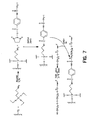
- Processes for immobilizing a high density of nucleic acids on a surface which are based on rapidly reacting a free thiol group of a modified surface or modified nucleic acid, under appropriate conditions, with a thiol-reactive functionality of the other component (surface or nucleic acid) are provided.
- This reaction may be direct or through a bifunctional cross-linking reagent.
- the modified nucleic acid includes a thiol group and the cross-linking reagent contains an iodoacetyl group.
- Solid supports to which are linked “beads” which are linked to nucleic acid molecules are also provided.
- the beads are not necessarily spherical, but refer to particles that are conjugated to the solid support to thereby increase the surface area of the solid support and/or to provide an alternative surface for conjuation of nucleic acids or other molecules.
- the beads are preferably of a size of about 1 ⁇ m to 100 ⁇ m.
- Compositions containing at least one bead conjugated to a solid support and further conjugated to at least one molecule, particularly a nucleic acid are provided.
- the bead is formed from any suitable matrix material known to those of skill in the art, including those that are swellable and nonswellable.
- the solid support is any support known to those of skill in the art for use as a support matrix in chemical syntheses and analyses.
- the nucleic acid is linked to the "bead” via a sulfur atom as described herein.
- the beads may be conjugated on the solid support in wells or pits on the surface, or the beads may be arranged in the form of an array on the support.
- the bead is made of a material selected from materials that serve as solid supports for synthesis and for assays including but not limited to: silica gel, glass, magnet, polystyrene/1 % divinylbenzene resins, such as Wang resins, which are Fmoc-amino acid-4-(hydroxy-methyl)phenoxymethylcopoly(styrene-1% divinylbenzene (DVD)) resin, chlorotrityl (2-chlorotritylchloride copolystyrene-DVB resin) resin, Merrifield (chloromethylated copolystyrene-DVB) resin metal, plastic, cellulose, cross-linked dextrans, such as those sold under the tradename Sephadex (Pharmacia) and agarose gel, such as gels sold under the tradename Sepharose (Pharmacia), which is a hydrogen bonded polysaccharide-type agarose gel, and other such resins and solid phase supports known to those of skill
- the solid support is in any desired form, including, but not limited to: a bead, capillary, plate, membrane, wafer, comb, pin, a wafer with pits, an array of pits or nanoliter wells and other geometries and forms known to those of skill in the art.
- kits for immobilized nucleic acids on an insoluble support can comprise an appropriate amount of: i) a thiol-reactive cross-linking reagent; and ii) a surface-modifying reagent for modifying a surface with functionality which can react with the thiol-reactive cross-linking reagent.
- the kit can optionally include an insoluble support, e.g., a solid surface, magnetic microbeads or silicon wafers, for use in immobilizing nucleic acids.
- the kit can also optionally include appropriate buffers as well as instructions for use.
- nucleic acids immobilized on a surface using the methods provided herein can be used in a variety of solid phase nucleic acid chemistry applications, including but not limited to nucleic acid synthesis (chemical and enzymatic), hybridization and/or extension, and in diagnostic methods based in nucleic acid detection and polymorphism analyses (see, e.g., U.S. Patent No. 5,605,798).
- nucleic acid molecules in which the nucleic acid molecules are immobilized on a surface either by reacting a thiol-containing derivative of the nucleic acid molecule with an insoluble support containing a thiol-reactive group or by reacting a thiol-containing insoluble support with a thiol-reactive group-containing derivative of the nucleic acid molecule and thereafter further reacting the immobilized nucleic acid molecules.
- the immobilized nucleic acid is further reacted by hybridizing with a nucleic acid that is complementary to the immobilized nucleic acid or a portion thereof.
- hybridization reactions can be used to detect the presence of a specific nucleic acid in a sample. This is of particular use in the detection of pathogens in a sample, such as a biological sample, that may be employed in the diagnosis of diseases.
- a target nucleic acid in a sample wherein a thiol-containing nucleic acid complementary to the target nucleic acid is immobilized to a surface using the processes described herein and the sample is contacted with the surface under conditions whereby target nucleic acid in the sample hybridizes to the immobilized nucleic acid.
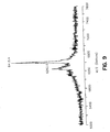
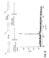
- the hybridized target nucleic acid may be detected using a variety of methods, the preferred method being mass spectrometry. Further provided herein are methods of detecting alterations (e.g., deletions, insertions and conversions) in the nucleotide sequence of the target nucleic acid.
- the molecular weight of the hybridized target nucleic acid is compared to the molecular weight expected for the target nucleic acid sequence. Deviations of the measured molecular weight from the expected molecular weight are indicative of an alteration in the nucleotide sequence of the target nucleic acid.
- the target nucleic acid is immobilized to a surface containing thiol-reactive groups.
- the target nucleic acid prior to immobilization, is amplified in a reaction in which an oligonucleotide primer contains a 3'- or 5'-disulfide linkage and the resulting product is reduced to generate a thiol-containing nucleic acid.
- the thiol-containing nucleic acid is immobilized to a surface containing thiol-reactive groups and is contacted with a single-stranded nucleic acid that is complementary to the immobilized nucleic acid or a portion thereof.
- Hybridization of the single-stranded nucleic acid may be detected by a variety of methods.
- the single-stranded nucleic acid may be labeled with a readily detectable moiety, e.g., radioactive or chemiluminescent labels.
- the single-stranded nucleic acid is detected by mass spectrometry.
- the immobilized nucleic acid is further reacted by extension of a nucleic acid that is hybridized to the immobilized nucleic acid or a portion thereof.
- Extension reactions such as these can be used, for example, in methods of sequencing DNA molecules that are immobilized to an insoluble support using the processes described herein.
- a thiol-containing derivative of the DNA molecule is immobilized on the surface of an insoluble support containing thiol-reactive groups and hybridized with a single-stranded nucleic acid complementary to a portion of the immobilized DNA molecule prior to carrying out DNA synthesis in the presence of one or more dideoxynucleotides.
- Extension of a nucleic acid primer that is hybridized to a nucleic acid immobilized to a surface as provided herein also can be used in the detection of nucleotide sequence alterations (e.g. , deletions, insertions, conversions) of a target nucleic acid. Accordingly, provided herein are methods of detecting alterations in a target nucleic acid sequence in which a single-stranded nucleic acid is hybridized to a thiol-containing target nucleic acid immobilized to a solid support according to the processes provided herein and the hybridized single-stranded nucleic acid is extended by addition of nucleotides to the 3' end of the molecule.
- nucleotide sequence alterations e.g. , deletions, insertions, conversions
- the extension product is characterized by, for example, mass spectrometry to determine whether its characteristics differ from those expected of a sequence complementary to the immobilized target nucleic acid.
- mass spectrometry to determine whether its characteristics differ from those expected of a sequence complementary to the immobilized target nucleic acid.
- the molecular weight of the extension product determined by mass spectrometry is compared to the expected molecular weight of a nucleic acid complementary to the target nucleic acid. Deviations from the expected molecular weight are indicative of an alteration in the sequence of the target nucleic acid.
- the target nucleic acid may be amplified prior to immobilization to a thiol-reactive surface in a reaction in which an oligonucleotide primer contains a 3'- or 5'-disulfide linkage.
- the resulting product is reduced to generate a thiol-containing target nucleic acid.
- the thiol-containing target nucleic acid is then immobilized to a surface containing thiol-reactive groups and the single-stranded complementary nucleic acid is hybridized thereto and extended.
- a single-stranded nucleic acid complementary to the target nucleic acid is immobilized to a surface through a linkage that includes a thiol group-thiol reactive functionality bond and a cleavable linker moiety.
- the sample containing target nucleic acid is contacted with the surface under conditions whereby the target hybridizes with the immobilized single-stranded nucleic acid.
- the immobilized single-stranded nucleic acid is extended by addition of nucleotides to the 3' end of the molecule.
- the double-stranded molecule is denatured and the single-stranded immobilized extension product is cleaved from the surface at the position of the linker.
- the extension product is characterized by, for example, mass spectrometry to determine whether its characteristics differ from those expected of a sequence complementary to the immobilized target nucleic acid.
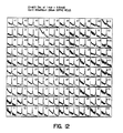
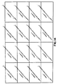
- Methods of forming an array of nucleic acids on a surface of a substrate by contacting thiol-containing nucleic acids with an insoluble support containing thiol-reactive groups positioned in an ordered arrangement on the surface of the support are also provided herein.
- an insoluble support containing thiol functionalities positioned in an ordered arrangement on the surface of the support is contacted with nucleic acids containing a thiol-reactive group.
- Systems and methods for preparing a sample for analysis are generally less expensive to employ and conserve reagent materials while allowing for the rapid production of highly reproducible sample arrays.
- serial and parallel dispensing tools that can be employed to generate multi-element arrays of sample material on a substrate surface.
- the substrate surfaces can be flat or geometrically altered to include wells of receiving material.
- the tool is one that allows the parallel development of a sample array.
- the tool can be understood as an assembly of vesicle elements, or pins, wherein each of the pins can include a narrow interior chamber suitable for holding nanoliter volumes of fluid.
- Each of the pins can fit inside a housing that itself has an interior chamber.
- the interior housing can be connected to a pressure source that will control the pressure within the interior housing chamber to regulate the flow of fluid through the interior chamber of the pins. This allows for the controlled dispensing of defined volumes of fluid from the vesicles.
- the tool includes a jet assembly that can include a capillary pin having an interior chamber, and a transducer element mounted to the pin and capable of driving fluid through the interior chamber of the pin to eject fluid from the pin.
- the tool can dispense a spot of fluid to a substrate surface by spraying the fluid from the pin.
- the transducer can cause a drop of fluid to extend from the capillary so that fluid can be passed to the substrate by contacting the drop to the surface of the substrate.
- the tool can form an array of sample material by dispensing sample material in a series of steps, while moving the pin to different locations above the substrate surface to form the sample array.
- the prepared sample arrays are passed to a plate assembly that disposes the sample arrays for analysis by mass spectrometry.
- a mass spectrometer is provided that generates a set of spectra signal which can be understood as indicative of the composition of the sample material under analysis.
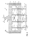
- the dispensing apparatus for dispensing defined volumes of fluid, including nanovolumes and subnanovolumes of fluid, in chemical or biological procedures onto the surface of a substrate can include a housing having a plurality of sides and a bottom portion having formed therein a plurality of apertures, the walls and bottom portion of the housing defining an interior volume; one or more fluid transmitting vesicles, or pins, mounted within the apertures, having a nanovolume sized fluid holding chamber for holding nanovolumes of fluid, the fluid holding chamber being disposed in fluid communication with the interior volume of the housing, and a dispensing element that is in communication with the interior volume of the housing for selectively dispensing nanovolumes of fluid from the nanovolume sized fluid transmitting vesicles when the fluid is loaded into the fluid holding chambers of the vesicles.
- this allows the dispensing element to dispense nanovolumes of the fluid onto the surface of the substrate when the apparatus is disposed over and in registration with the substrate.
- the fluid transmitting vesicle has an open proximal end and a distal tip portion that extends beyond the housing bottom portion when mounted within the apertures.
- the open proximal end can dispose the fluid holding chamber in fluid communication with the interior volume when mounted with the apertures.
- the plurality of fluid transmitting vesicles are removably and replaceably mounted within the apertures of the housing, or alternatively can include a glue seal for fixedly mounting the vesicles within the housing.
- the fluid holding chamber includes a narrow bore dimensionally adapted for being filled with the fluid through capillary action, and can be sized to fill substantially completely with the fluid through capillary action.
- the plurality of fluid transmitting vesicles comprise an array of fluid delivering needles, which can be formed of metal, glass, silica, polymeric material, or any other suitable material.
- the housing can include a top portion, and mechanical biasing elements for mechanically biasing the plurality of fluid transmitting vesicles into sealing contact with the housing bottom portion.
- each fluid transmitting vesicle has a proximal end portion that includes a flange, and further includes a seal element disposed between the flange and an inner surface of the housing bottom portion for forming a seal between the interior volume and an external environment.
- the biasing elements can be mechanical and can include a plurality of spring elements each of which is coupled at one end to the proximal end of each of the plurality of fluid transmitting vesicles, and at another end to an inner surface of the housing top portion. The springs can apply a mechanical biasing force to the vesicle proximal end to form the seal.
- the housing further includes a top portion, and securing element for securing the housing top portion to the housing bottom portion.
- the securing element can comprise a plurality of fastener-receiving apertures formed within one of the top and bottom portions of the housing, and a plurality of fasteners for mounting within the apertures for securing together the housing top and bottom portions.
- the dispensing element can comprise a pressure source fluidly coupled to the interior volume of the housing for disposing the interior volume at a selected pressure condition.
- the dispensing element can include a pressure controller that can vary the pressure source to dispose the interior volume of the housing at varying pressure conditions. This allows the controller varying element to dispose the interior volume at a selected pressure condition sufficient to offset the capillary action to fill the fluid holding chamber of each vesicle to a predetermined height corresponding to a predetermined fluid amount.
- the controller can further include a fluid selection element for selectively discharging a selected nanovolume fluid amount from the chamber of each vesicle.
- a pressure controller is included that operates under the controller of a computer program operating on a data processing system to provide variable control over the pressure applied to the interior chamber of the housing.
- the fluid transmitting vesicle can have a proximal end that opens onto the interior volume of the housing, and the fluid holding chamber of the vesicles are sized to substantially completely fill with the fluid through capillary action without forming a meniscus at the proximal open end.
- the apparatus can have plural vesicles, wherein a first portion of the plural vesicles include fluid holding chambers of a first size and a second portion including fluid holding chambers of a second size, whereby plural fluid volumes can be dispensed.
- the dispensing apparatus can include a fluid selection element that has a pressure source coupled to the housing and in communication with the interior volume for disposing the interior volume at a selected pressure condition, and an adjustment element that couples to the pressure source for varying the pressure within the interior volume of the housing to apply a positive pressure in the fluid chamber of each of the fluid transmitting vesicles to vary the amount of fluid dispensed therefrom.
- the selection element and adjustment element can be computer programs operating on a data processing system that directs the operation of a pressure controller connected to the interior chamber.
- the apparatus provided herein is for dispensing a fluid in chemical or biological procedures into one or more wells of a multi-well substrate.
- the apparatus can include a housing having a plurality of sides and a bottom portion having formed therein a plurality of apertures, the walls and bottom portion defining an interior volume, a plurality of fluid transmitting vesicles, mounted within the apertures, having a fluid holding chamber disposed in communication with the interior volume of the housing, and a fluid selection and dispensing means in communication with the interior volume of the housing for variably selecting am amount of the fluid loaded within the fluid holding chambers of the vesicles to be dispensed from a single set of the plurality of fluid transmitting vesicles. Accordingly, the dispensing means dispenses a selected amount of the fluid into the wells of the multi-well substrate when the apparatus is disposed over and in registration with the substrate.
- a fluid dispensing apparatus for dispensing fluid in chemical or biological procedures into one or more wells of a multi-well substrate, that comprises a housing having a plurality of sides and top and bottom portions, the bottom portion having formed therein a plurality of apertures, the walls and top and bottom portions of the housing defining an interior volume, a plurality of fluid transmitting vesicles, mounted within the apertures, having a fluid holding chamber sized to hold nanovolumes of the fluid, the fluid holding chamber being disposed in fluid communication with the volume of the housing, and mechanical biasing element for mechanically biasing the plurality of fluid transmitting vesicles into sealing contact with the housing bottom portion.
- General methods for preparing an array of sample material on a surface of a substrate as described herein include the steps of providing a vesicle having an interior chamber containing a fluid, disposing the vesicle adjacent a first location on the surface of the substrate, controlling the vessel for delivering a nanoliter volume of a fluid at the first location of the surface of the substrate, and moving the vesicle to a set of positions adjacent to the surface substrate whereby fluid is dispensed at each location of the set of positions for forming an array of sample material.
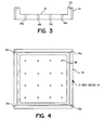
- Substrates employed during the general processes of preparing an array of sample material described herein can include flat surfaces for receiving the sample material as well as having the surfaces that include wells formed on the surface for defining locations for receiving the fluid that can be ejected from the chambers of the vesicles.
- Such substrates can be silicon, metal, plastic, a membrane, polymeric material, a metal-grafted polymer, as well as a substrate that is functionalized chemically, functionalized with beads, functionalized with dendrite trees of captured material, or any combinations of the above or any similar suitable material for receiving the dispensed fluid.
- the apparatus can dispense both an analyte material as well as a support material, such as a matrix material, that aids in the analysis of the analyte.
- the methods provided herein can include the steps of depositing a matrix material onto the substance of the substrate. Further the methods can also include a step of waiting a predetermined period of time to allow a solvent of the matrix material to evaporate. Once the solvent of the matrix material has evaporated, the methods herein can include a step of ejecting a volume of analyte fluid into the evaporated matrix material to dissolve with the matrix material and to form a crystalline structure on the substrate surface. It is understood that this step of redissolving the matrix material with the analyte material aids in the analysis of the composition of the material during certain analytical processes, such as mass spectrometry.
- the methods herein can include a step of dispensing a mixture that consists of the analyte material and the matrix material, as well as other material compositions. In this way the matrix and the analyte are delivered to the surface of the substrate as one volume of material.
- the prepared arrays of sample material can be provided to a diagnostic tool for determining information that is representative of the composition of the sample material.
- the diagnostic tool can include a mass spectrometer.
- the mass spectrometers can be time of flight mass spectrometers, fourier transform mass spectrometers or any other suitable type of mass spectrometer that allows the analysis of composition of the sample array.
- the step of providing a vesicle having an interior chamber includes the step of providing a vesicle having a piezo electric element for causing fluid to move through the chamber.
- This method can also include the step of moving the vesicle by rasterizing the vesicle across the surface of the substrate, to form the array of sample material.
- the vesicle that is employed during the processing includes a vesicle assembly that has a plurality of vesicles arranged into a matrix for dispensing fluid to a first plurality of locations on the substrate surface.
- the method provides for forming a matrix of a sample material on the substrate surface.
- Offset printing can also be employed to form a large matrix of sample material by employing multiple printing steps with the vesicle matrix.
- Other printing techniques can be employed by the present invention without departing from the scope thereof.
- fluid can be dispensed to the surface of the substrate by contacting the vesicle against the surface of the substrate to spot the surface of the substrate with sample material.
- the methods provide for another non-contact printing approach wherein the processes of the invention cause a drop of fluid to be formed on at the distal tip of the vesicle. It is the drop of fluid that is contacted against the surface of the substrate for delivering sampling material thereto. This provides for the controlled delivery for the known volume of fluid without resulting in the contacting of the vesicle against the surface of the substrate.
- vesicles are provided having an interior chamber that is dimensionally adapted to allow filling of the chamber by capillary action.
- methods for analyzing a material comprise the steps of providing a vesicle suitable for carrying a fluid having the material therein, disposing the vesicle adjacent a first location of the surface of the substrate, controlling the vesicle to deliver a nanoliter volume of the fluid to provide a defined and controlled volume of fluid at the first location of the surface of the substrate, moving the vesicle to a second position adjacent a second location on the surface on the substrate to dispense a defined and controlled volume of the material along an array of locations along the substrate surface, and performing mass spectrometry analysis of the material at each location of the array.
- These methods can include the step of mixing a matrix material and an analyte material to form the fluid being delivered to the substrate surface.
- this embodiment can include the steps of filling a chamber contained within the vesicle with a matrix material and dispensing the matrix material to the array of locations. Subsequently, analyte can be dispensed.
- the step of performing mass spectrometry can include the step of performing a matrix assisted laser desorption ionization mass spectrometry, as well as time of flight mass spectrometry, or a fourier transform spectrometry.
- apparatus for forming an array of a sample material on a surface of a substrate will compromise a vesicle having a distal end suitable for carrying a fluid thereon, a movable arm having a distal portion mounted to the vesicle, a controller for moving the arm to dispose the vesicle adjacent a first location on the surface on the substrate and for controlling the vesicle to provide a nanoliter volume of the fluid at the first location of the surface of the substrate, and a diagnostic tool for analyzing the material to generate a composition signal that is representative of the chemical composition of the material.
- the vesicle can compromise a solid shaft of material as well as a vesicle having an interior chamber suitable for carrying fluid as well as a chamber for carrying a fluid in a transducer element for ejecting fluid from that chamber.
- substrates having a surface for carrying an array of a matrix material and formed according to a process comprising the steps of a providing a vesicle suitable for transferring a fluid containing a matrix material, disposing the vesicle adjacent a first location on the surface on the substrate, controlling the vesicle to deliver the fluid to the first location of the surface of the substrate, and moving a vesicle to a set of positions adjacent the surface of the substrate and delivering fluid at each of these locations to form an array of matrix material.
- This substrate itself can be a flat silicon chip as well as a any other suitable material, and can be pitted, include wells, and have wells that have rough interior surfaces.
- the methods of forming an array of nucleic acids on a surface of a substrate as provided herein include contacting predetermined positions of the surface of an insoluble support with thiol-containing nucleic acid solutions dispensed to the positions with a vesicle having an interior chamber containing the respective solutions whereby the predetermined positions incorporate thiol-reactive groups.
- the entire surface of the substrate is derivatized with the thiol-reactive groups and thiol-containing nucleic acid is dispensed to predetermined positions on the surface in an array-forming manner.
- nucleic acid refers to oligonucleotides or polynucleotides such as deoxyribonucleic acid (DNA) and ribonucleic acid (RNA) as well as analogs of either RNA or DNA, for example, made from nucleotide analogs, any of which are in single or double-stranded form.
- Nucleic acid molecules can be synthetic or can be isolated from a particular biological sample using any number of procedures which are well-known in the art, the particular procedure chosen being appropriate for the particluar biological sample.
- nucleotides include nucleoside mono-, di-, and triphosphates. Nucleotides also include modified nucleotides such as phosphorothioate nucleotides and deazapurine nucleotides. A complete set of chain-elongating nucleotides refers to four different nucleotides that can hybridize to each of the four different bases comprising the DNA template.
- nucleic acid synthesis refers to any process by which oligonucleotides or polynucleotides are generated, including, but not limited to processes involving chemical or enzymatic reactions.
- the term "array” refers to an ordered arrangement of members or positions.
- the array may contain any number of members or positions and can be in any variety of shapes.
- the array is two-dimensional and contains n x m members, wherein m and n are integers that can be the same or different.
- n and m are each 4 or a multiple thereof.
- cross-linking agent is art-recognized, and, as used herein, refers to reagents which can immobilize a nucleic acid to an insoluble-support, preferably through covalent bonds.
- appropriate "cross-linking agents” for use herein includes a variety of agents that are capable of reacting with a functional group present on a surface of the insoluble support and with a functional group present in the nucleic acid molecule.
- Reagents capable of such reactivity include homo- and heterobifunctional reagents, many of which are known in the art. Heterobifunctional reagents are preferred.
- thiol-reactive functionality refers to a functionality which is capable of rapid reaction with a nucleophilic thiol moiety to produce a covalent bond (e.g., a disulfide or thioether bond).
- thiol groups are good nucleophiles, and preferred thiol-reactive functionalities are reactive electrophiles.
- thiol-reactive functionalities include, for example, haloacetyls (preferably iodoacetyl), diazoketones, epoxy ketones, ⁇ , ⁇ -unsaturated carbonyls (e.g., ⁇ , ⁇ -enones) and other reactive Michael acceptors (including maleimide), acid halides, benzyl halides, and the like.
- a free thiol group of a disulfide can react with a free thiol group (i.e., by disulfide bond formation, including by disulfide exchange).
- a “thiol-reactive" cross-linking agent refers to a cross-linking reagent (or surface) which includes, or can be modified to include, at least one thiol-reactive functionality. It will be understood that reaction of a thiol group can be temporarily prevented by blocking with an appropriate protecting group, as is conventional in the art (see e.g., T.W. Greene and P.G.M. Wuts "Protective Groups in Organic Synthesis," 2nd ed. John Wiley & Sons, (1991)).
- a selectively cleavable linker is a linker that is cleaved under selected conditions, such as a photocleavable linker, a chemically cleavable linker and an enzymatically cleavable linker (i.e., a restriction endonuclease site or a ribonucleotide/RNase digestion).
- the linker is interposed between the support and immobilized DNA.
- protein As used herein, the terms “protein”, “polypeptide” and “peptide” are used interchangeably when referring to a translated nucleic acid (e.g. a gene product).
- sample shall refer to a composition containing a material to be detected.
- the sample is a "biological sample” (i.e., any material obtained from a living source (e.g. human, animal, plant, bacteria, fungi, protist, virus).
- the biological sample can be in any form, including solid materials (e.g. tissue, cell pellets and biopsies) and biological fluids (e.g. urine, blood, saliva, amniotic fluid and mouth wash (containing buccal cells)).
- solid materials e.g. tissue, cell pellets and biopsies
- biological fluids e.g. urine, blood, saliva, amniotic fluid and mouth wash (containing buccal cells).
- solid materials are mixed with a fluid.
- substrate shall mean an insoluble support onto which a sample is deposited according to the materials as described herein.
- appropriate substrates include beads (e.g., silica gel, controlled pore glass, magnetic, Sephadex/Sepharose, cellulose), capillaries, flat supports such as glass fiber filters, glass surfaces, metal surfaces (steel, gold, silver, aluminum, copper and silicon), plastic materials including multiwell plates or membranes (e.g., of polyethylene, polypropylene, polyamide, polyvinylidenedifluoride), pins (e.g., arrays of pins suitable for combinatorial synthesis or analysis or beads in pits of flat surfaces such as wafers (e.g., silicon wafers) with or without plates.
- beads e.g., silica gel, controlled pore glass, magnetic, Sephadex/Sepharose, cellulose
- capillaries flat supports such as glass fiber filters, glass surfaces, metal surfaces (steel, gold, silver, aluminum, copper and silicon), plastic materials including multiwell plates or membrane
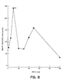
- preferred substrates are those which can support linkage of nucleic acids thereto at high densities, preferrably such that the covalently bound nucleic acids are present on the substrate at a density of at least about 20 fmol/mm 2 , more preferably at least about 75 fmol/mm 2 , still more preferably at least about 85 fmol/mm 2 , yet more preferably at least about 100 fmol/mm 2 , and most preferably at least about 150 fmol/mm 2 .
- silicon whereas less preferred substrates include polymeric materials such as polyacrylamide.
- Substrates for use in methods of producing arrays provided herein include any of a wide variety of insoluble support materials including, but not limited to silica gel, controlled pore glass, cellulose, glass fiber filters, glass surfaces, metal surfaces (steel, gold, silver, aluminum, silicon and copper), plastic materials (e.g., of polyethylene, polypropylene, polyamide, polyvinyldenedifluoride) and silicon.
- insoluble support materials including, but not limited to silica gel, controlled pore glass, cellulose, glass fiber filters, glass surfaces, metal surfaces (steel, gold, silver, aluminum, silicon and copper), plastic materials (e.g., of polyethylene, polypropylene, polyamide, polyvinyldenedifluoride) and silicon.
- nucleic acid molecules are immobilized on the insoluble support either directly or by means of cross-linking agents.
- a modified nucleic acid is reacted directly with a appropriately functionalized surface to yield immobilized nucleic acid.
- a iodoacetyl-modified surface or other thiol-reactive surface functionality
- the cross-linking agent is selected to provide a high density of nucleic acids immobilized on the insoluble support.
- the high density of immobilized nucleic acids described herein is due, at least in part, to a relatively rapid reaction occurring between the cross-linking agent and the nucleic acid (e.g., a thiol-modified nucleic acid), compared to other reactions previously used to immobilize nucleic acids.
- high density may at least in part be due to a close spacing of the reactive groups (e.g., amino groups of other reactive functionality) on the functionalized insoluble support.
- reagents for modifying the surface will generally be selected to provide closely-spaced functionalities on the functionalized support.
- the cross-linking agent (and other reagents used to functionalize the support surface or the nucleic acid molecule) can be selected to provide any desired spacing of the immobilized nucleic acid molecules from the support surface, and to provide any desired spacing of the immobilized nucleic acids from each other.
- steric encumbrance of the nucleic acid molecules can be reduced or eliminated by choice of an appropriate cross-linking agent.
- the cross-linking reagent can be selected to provide multiple reactive functionalities as used in dendrimer synthesis for attachment of multiple nucleic acids to a single cross-linking moiety.
- the cross-linking agent is selected to be highly reactive with the nucleic acid molecule, to provide rapid, complete, and/or selective reaction.
- the reaction volume of the reagents e.g., the thiol group and the thiol-reactive functionality
- nucleic acids for use herein are "thiol-modified nucleic acids," i.e., nucleic acids derivatized to contain at least one reactive thiol moiety.
- nucleic acids containing at least one reactive thiol are preferably made by treating a nucleic acid containing a 3' or 5' disulfide with a reducing agent, which preferably will not compete in subsequent reactions (i.e. will not react with an iodoacetimido functionality.
- Disulfide-derivatized nucleic acids can be synthesized according to a variety of methods.
- a nucleic acid can be modified at the 3'- or 5'-terminus by reaction with a disulfide-containing modifying a reagent.
- a thiolated primer can by enzymatically or non-enzymatically attached to the nucleic acid.
- a 5'-phosphoramidate functionality can also provide an attachment point for a thiol or disulfide-containing cytosine or deoxycytosine.
- reducing agents appropriate for reduction of a disulfide-modified nucleic acid include: tris-(2-carboxyethyl)phosphine (TCEP) (preferably a concentration in the range of 1-100mM (most preferably about 10mM)) is reacted at a pH in the range of 3-6 (most preferably about 4.5), a temperature in the range of 20-45°C (most preferably about 37°C) for a time period in the range of about 1 to about 10 hrs (most preferably for about 5 hrs); dithiothreitol (preferably a concentration in the range of 25 to 100mM (depending on whether the reactant is isolated) is reacted at a pH in the range of 6-10 (most preferably about 8) and at a temperature in the range of 25-45°C (most preferably about 37°C)) for a time in the range of about 1 to about 10 hrs (most preferably about 5 hrs).
- TCEP tris-(2-carboxyethyl
- TCE provides an advantage in the low pH at which it is reactive. This low pH effectively protonates thiols, thus suppressing nucleophilic reactions of thiols and resulting in fewer side reactions than with other disulfide reducing agents which are employed at higher pH.
- a preferred bifunctional cross-linking agent is N-succinimidyl(4-iodacetyl) aminobenzoate (SIAB).
- Other crosslinking agents include, but are not limited to, dimaleimide, dithio-bis-nitrobenzoic acid (DTNB), N-succinimidyl-S-acetyl-thioacetate (SATA), N-succinimidyl-3-(2-pyridyldithiol propionate (SPDP), succinimidyl 4-(N-maleimidomethyl)cyclohexane-1-carboxylate (SMCC) ad 6-hydrazinonicotimide (HYNIC) may also be used in the novel process.
- cross-linking reagents see, e.g., Wong "Chemistry of Protein Conjugation and Cross- Linking," CRC Press (1991), and Hermanson, "Bioconjugate Techniques” Academic Press (1995).
- the nucleic acid is immobilized using the photocleavable linker moiety that is cleaved during mass spectrometry.
- exemplary photolabile cross-linker include, but are not limited to, 3-amino-(2-nitrophenyl)propionic acid (Brown et al. (1995) Molecular Diversity, pp.4-12 and Rothschild et al. (1996) Nucleic Acids Res. 24: 361-66).
- a single-stranded nucleic acid complementary to the target nucleic acid is immobilized to a surface through a linkage that includes a thiol group-thiol reactive functionality bond and a cleavable, preferably a selectively cleavable, linker moiety.
- a target detection site can be directly linked to a solid support via a reversible or irreversible bond between an appropriate functionality (L') on the target nucleic acid molecule (T) and an appropriate functionality (L) on the capture molecule.
- a reversible linkage can be such that it is cleaved under the conditions of mass spectrometry (i.e., a photocleavable bond such as a charge transfer complex or a labile bond being formed between relatively stable organic radicals).
- Photocleavable linkers are linkers that are cleaved upon exposure to light (see, e.g., Goldmacher et al. (1992) Bioconj. Chem. 3 :104-107), thereby releasing the targeted agent upon exposure to light.
- Photocleavable linkers that are cleaved upon exposure to light are known (see, e.g., Hazum et al. (1981) in Pept., Proc. Eur. Pept. Symp., 16th, Brunfeldt, K (Ed), pp. 105-110, which describes the use of a nitrobenzyl group as a photocleavable protective group for cysteine; Yen et al. (1989) Makromol.
- Chem 190 :69-82 which describes water soluble photocleavable copolymers, including hydroxypropylmethacrylamide copolymer, glycine copolymer, fluorescein copolymer and methylrhodamine copolymer; Goldmacher et al. (1992) Bioconj. Chem. 3 :104-107, which describes a cross-linker and reagent that undergoes photolytic degradation upon exposure to near UV light (350 nm); and Senter et al. (1985) Photochem. Photobiol 42 :231-237, which describes nitrobenzyloxycarbonyl chloride cross linking reagents that produce photocleavable linkages), thereby releasing the targeted agent upon exposure to light.
- the nucleic acid is immobilized using the photocleavable linker moiety that is cleaved during mass spectrometry.
- the linkage can be formed with L' being a quaternary ammonium group, in which case, preferably, the surface of the solid support carries negative charges which repel the negatively charged nucleic acid backbone and thus facilitate the desorption required for analysis by a mass spectrometer. Desorption can occur either by the heat created by the laser pulse and/or, depending on L,' by specific absorption of laser energy which is in resonance with the L' chromophore.
- the L-L' chemistry can be of a type of disulfide bond (chemically cleavable, for example, by mercaptoethanol or dithioerythrol), a biotin/streptavidin system, a heterobifunctional derivative of a trityl ether group (see, e.g., Köster et al.
- the functionalities, L and L,' can also form a charge transfer complex and thereby form the temporary L-L' linkage. Since in many cases the "charge-transfer band" can be determined by UV/vis spectrometry (see, e.g., Organic Charge Transfer Complexes by R. Foster, Academic Press, 1969), the laser energy can be tuned to the corresponding energy of the charge-transfer wavelength and, thus, a specific desorption off the solid support can be initiated. Those skilled in the art will recognize that several combinations can serve this purpose and that the donor functionality can be either on the solid support or coupled to the nucleic acid molecule to be detected or vice versa.
- a reversible L-L' linkage can be generated by homolytically forming relatively stable radicals. Under the influence of the laser pulse, desorption (as discussed above) as well as ionization will take place at the radical position.
- desorption as discussed above
- ionization will take place at the radical position.
- other organic radicals can be selected and that, in relation to the dissociation energies needed to homolytically cleave the bond between them, a corresponding laser wavelength can be selected (see e.g., Reactive Molecules by C. Wentrup, John Wiley & Sons, 1984).
- a single stranded DNA molecule immobilized via its 5-end to a solid support is unilaterally degraded with a 3'-processive exonuclease and the molecular weight of the degraded nucleotide is determined sequentially.
- Reverse Sanger sequencing reveals the nucleotide sequence of the immobilized DNA.
- this cleavage can be selected to occur during the ionization and volatizing steps of MALDI-TOF.
- This also applies when using a 5'-processive exonuclease and the DNA is immobilized through the 3'-end to the solid support.
- the target nucleic acid is amplified or obtained (the target sequence or surrounding DNA sequence must be known to make primers to amplify or isolated); 2) the primer nucleic acid is immobilized to the solid support and the target nucleic acid is hybridized thereto (this is for detecting the presence of or sequencing a target sequence in a sample); or 3) a double stranded DNA (amplified or isolated) is immobilized through linkage to one predetermined strand, the DNA is denatured to eliminate the duplex and then a high concentration of a complementary primer or DNA with identity upstream from the target site is added and a strand displacement occurs and the primer is hybridized to the immobilized strand.
- the inclusion of the cleavable linker allows the primer DNA to be immobilized at the 5'-end so that free 3'-OH is available for nucleic acid synthesis (extension) and the sequence of the "hybridized" target DNA can be determined because the hybridized template can be removed by denaturation and the extended DNA products cleaved from the solid support for MALDI-TOF MS.
- the immobilized DNA strand can be elongated when hybridized to the template and cleaved from the support.
- extension reactions can be performed using an immobilized primer of a known, upstreamn DNA sequence complementary to an invariable region of a target sequence.
- the nucleic acid from the person is obtained and the DNA sequence of a variable region (deletion, insertion, missense mutation that cause genetic predisposition or diseases, or the presence of viral/bacterial or fungal DNA) not only is detected, but the actual sequence and position of the mutation is also determined.
- the target DNA must be immobilized and the primer annealed. This requires amplifying a larger DNA based on known sequence and then sequencing the immobilized fragments (i.e., the extended fragments are hybridized but not immobilized to the support as described above). In these cases, it is not desirable to include a linker because the MALDI-TOF spectrum is of the hybridized DNA; it is not necessary to cleave the immobilized template.
- linker known to those of skill in the art for immobilizing nucleic acids to solid supports may be used herein to link the nucleic acid to a solid support.
- the preferred linkers herein are the selectively cleavable linkers, particularly those exemplified herein.
- Other linkers include, acid cleavable linkers, such as bismaleimideothoxy propane, acid-labile trityl linkers.
- Acid cleavable linkers, photocleavable and heat sensitive linkers may also be used, particularly where it may be necessary to cleave the targeted agent to permit it to be more readily accessible to reaction.
- Acid cleavable linkers include, but are not limited to, bismaleimideothoxy propane; and adipic acid dihydrazide linkers (see, e.g., Fattom et al. (1992) Infection & Immun. 60 :584-589) and acid labile transferrin conjugates that contain a sufficient portion of transferrin to permit entry into the intracellular transferrin cycling pathway (see, e.g., Welhöner et al. (1991) J. Biol. Chem. 266 :4309-4314).
- Photocleavable linkers are provided.
- photocleavable linkers as their phosphoramidite derivatives are provided for use in solid phase synthesis of oligonucleotides.
- the linkers contain o-nitrobenzyl moieties and phosphate linkages which allow for complete photolytic cleavage of the conjugates within minutes upon UV irradiation.
- the UV wavelengths used are selected so that the irradiation will not damage the oligonucleotides and are preferrably about 350-380 nm, more preferably 365 nm.
- the photocleavable linkers provided herein possess comparable coupling efficiency as compared to commonly used phosphoramidite monomers (see, Sinha et al. (1983) Tetrahedron Lett.
- the photocleavable linkers have formula I: where R 20 is ⁇ -(4,4'-dimethoxytrityloxy)alkyl or ⁇ -hydroxyalkyl; R 21 is selected from hydrogen, alkyl, aryl, alkoxycarbonyl, aryloxycarbonyl and carboxy; R 22 is hydrogen or (dialkylamino)( ⁇ -cyanoalkoxy)P-; t is 0-3; and R 50 is alkyl, alkoxy, aryl or aryloxy.
- the photocleavable linkers have formula II: where R 20 is ⁇ -(4,4'-dimethoxytrityloxy)alky), ⁇ -hydroxyalkyl or alkyl; R 21 is selected from hydrogen, alkyl, aryl, alkoxycarbonyl, aryloxycarbonyl and carboxy; R 22 is hydrogen or (dialkylamino)( ⁇ -cyanoalkoxy)P-; and X 20 is hydrogen, alkyl or OR 20 .
- R 20 is 3-(4,4'-dimethoxytrityloxy)propyl, 3-hydroxypropyl or methyl;
- R 21 is selected from hydrogen, methyl and carboxy;
- R 22 is hydrogen or (diisopropylamino)(2-cyanoethoxy)P-;
- X 20 is hydrogen, methyl or OR 20 .
- R 20 is 3-(4,4'-dimethoxytrityloxy)propyl; R 21 is methyl; R 22 is (diisopropylamino)(2-cyanoethoxy)P-; and
- X 20 is hydrogen.
- R 20 is methyl; R 21 is methyl; R 22 is (diisopropylamino)(2-cyanoethoxy)P-; and X 20 is 3-(4,4'-dimethoxytrityloxy)propoxy.
- the photocleavable linkers have formula III.
- R 23 is hydrogen or (dialkylamino)( ⁇ -cyanoalkoxy)P-; and R 24 is selected from ⁇ -hydroxyalkoxy, ⁇ -(4,4'-dimethoxytrityloxy)alkoxy, ⁇ -hydroxyalkyl and ⁇ -(4,4'-dimethoxytrityloxy)alkyl, and is unsubstituted or substituted on the alkyl or alkoxy chain with one or more alkyl groups; r and s are each independently O-4; and R 50 is alkyl, alkoxy, aryl or aryloxy.
- R 24 is ⁇ -hydroxyalkyl or ⁇ -(4,4'-dimethoxytrityloxy)alkyl, and is substituted on the alkyl chain with a methyl group.
- R 23 is hydrogen or (diisopropylamino)(2-cyanoethoxy)P-; and R 24 is selected from 3-hydroxypropoxy, 3-(4,4'-dimethoxytrityloxy)propoxy, 4-hydroxybutyl, 3-hydroxy-1-propyl, 1-hydroxy-2-propyl, 3-hydroxy-2-methyl-1-propyl, 2-hydroxyethyl, hydroxymethyl, 4-14,4'-dimethoxytrityloxy)butyl, 3-(4,4'-dimethoxytrityloxy)-1-propyl, 2-(4,4'-dimethoxytrityloxy)ethyl, 1-(4,4'-dimethoxytrityloxy)-2-propyl, 3-(4,4'-dimethoxytriyloxy)-2-methyl-1-propyl and 4,4'-dimethyoxytrityloxymethyl.
- R 23 is (diisopropylamino)(2-cyanoethoxy)P-; r and s are 0; and R 24 is selected from 3-(4,4'-dimethoxytrityloxy)propoxy, 4-(4,4'-dimethoxytrityloxy)butyl, 3-(4,4'-dimethoxytrityloxy)propyl, 2-(4,4'-dimethoxytrityloxy)ethyl, 1-(4,4'-dimethoxytrityloxy)-2-propyl, 3-(4,4'-dimethoxytriyloxy)-2-methyl-1-propyl and 4,4'-dimethyoxytrityloxymethyl.
- R 24 is most preferably 3-(4,4'-dimethoxytrityloxy)propoxy.
- Photocleavable linkers of formulae I or II may be prepared by the methods described below, by minor modification of the methods by choosing the appropriate starting materials or by any other methods known to those of skill in the art.
- the linkers may be prepared in the following manner. Alkylation of 5-hydroxy-2-nitrobenzaldehyde with an ⁇ -hydroxyalkyl halide, e.g., 3-hydroxypropyl bromide, followed by protection of the resulting alcohol as, e.g., a silyl ether, provides a 5-( ⁇ -silyloxyalkoxy)-2-nitrobenzaldehyde. Addition of an organometallic to the aldehyde affords a benzylic alcohol.
- an ⁇ -hydroxyalkyl halide e.g., 3-hydroxypropyl bromide
- Organometallics which may be used include trialkylaluminums (for linkers where R 21 is alkyl), such as trimethylaluminum, borohydrides (for linkers where R 21 is hydrogen), such as sodium borohydride, or metal cyanides (for linkers where R 21 is carboxy or alkoxycarbonyl), such as potassium cyanide.
- borohydrides for linkers where R 21 is hydrogen
- metal cyanides for linkers where R 21 is carboxy or alkoxycarbonyl
- potassium cyanide such as potassium cyanide.
- the product of the reaction, a cyanohydrin would then be hydrolyzed under either acidic or basic conditions in the presence of either water or an alcohol to afford the compounds of interest.
- the silyl group of the side chain of the resulting benzylic alcohols may then be exchanged for a 4,4'-dimethoxytriyl group by desilylation with, e.g., tetrabutylammonium fluoride, to give the corresponding alcohol, followed by reaction with 4,4'-dimethoxytrityl chloride.
- Reaction with, e.g., 2-cyanoethyl diisopropylchlorophosphoramidite affords the linkers where R 22 is (dialkylaminol( ⁇ -cyanoalkoxy)P-.
- This compound is then alkylated at the 4-hydroxyl by reaction with an ⁇ -hydroxyalkyl halide, e.g., 3-hydroxypropyl bromide, to give a 4-( ⁇ -hydroxyalkoxy)-3-alkoxyacetophenone.
- the side chain alcohol is then protected as an ester, e.g., an acetate.
- This compound is then nitrated at the 5-position with, e.g., concentrated nitric acid to provide the corresponding 2-nitroacetophenones.
- Photocleavable linkers of formula III may be prepared by the methods described below, by minor modification of the methods by choosing appropriate starting materials, or by other methods known to those of skill in the art.
- photocleavable linkers of formula III are prepared from ⁇ -hydroxyalkyl- or alkoxyaryl compounds, in particular ⁇ -hydroxy-alkyl or alkoxy-benzenes. These compounds are commercially available, or may be prepared from an ⁇ -hydroxyalkyl halide (e.g. , 3-hydroxypropyl bromide) and either phenyllithium (for the ⁇ -hydroxyalkylbenzenes) or phenol (for the ⁇ -hydroxyalkoxybenzenes).
- ⁇ -hydroxyalkyl- or alkoxyaryl compounds in particular ⁇ -hydroxy-alkyl or alkoxy-benzenes.
- linkers of formula II where R 23 is (dialkylaminol( ⁇ -cyanoalkoxy)P-.
- Other photocleavable linkers of formula III may be prepared by substituting 2-phenyl-1-propanol or 2-phenylmethyl-1-propanol for the ⁇ -hydroxy-alkyl or alkoxy-benzenes in the above synthesis.
- a variety of chemically cleavable linkers may be used to introduce a cleavable bond between the immobilized nucleic acid and the solid support.
- Acid-labile linkers are presently preferred chemically cleavable linkers for mass spectrometry, especially MALDI-TOF MS, because the acid labile bond is cleaved during conditioning of the nucleic acid upon addition of the 3-HPA matrix solution.
- the acid labile bond can be introduced as a separate linker group, e.g., the acid labile trityl groups or may be incorporated in a synthetic nucleic acid linker by introducing one or more silyl internucleoside bridges using diisopropylsilyl, thereby forming diisopropylsilyl-linked oligonucleotide analogs.
- the diisopropylsilyl bridge replaces the phoshodiester bond in the DNA backbone and under mildly acidic conditions, such as 1.5% trifluoroacetic acid (TFA) or 3-HPA/1% TFA MALDI-TOF matrix solution, results in the introduction of one or more intra-strand breaks in the DNA molecule.
- oligonucleotide precursors and analogs are known to those of skill in the art (see e.g., Saha et al. (1993) J. Org. Chem. 58 :7827-7831). These oligonucleotide analogs may be readily prepared using solid state oligonucleotide synthesis methods using diisopropylsilyl derivatized deoxyribonucleosides.
- nucleic acids modified at positions other than the 3'- or 5'- terminus can be used. Modification of the sugar moiety of a nucleotide at positions other than the 3' and 5' position is possible through concentional methods.
- nucleic acid bases can be modified, e.g., by modification of C-5 of dT with a linker arm, e.g., as described in F. Eckstein, ed., "Oligonucleotides and Analogues: A Practical Approach," IRL Press (1991).
- a linker arm can be modified to include a thiol moiety.
- backbone-modified nucleic acids e.g., phosoroamidate DNA
- the thiol group can be attached to the nitrogen center provided by the modified phosphate backbone.
- modification of a nucleic acid does not substantially impair the ability of the nucleic acid or nucleic sequence to hybridize to its complement.
- any modification should preferably avoid substantially modifying the functionalities of the nucleic acid which are responsible for Watson-Crick base pairing.
- the nucleic acid can be modified such that a non-terminal thiol group is present, and the nucleic acid, when immobilized to the support, is capable of self-complementary base pairing to form a "hairpin" structure having a duplex region.
- insoluble supports and substrates for use herein include, but are not limited to, beads (silica gel, controlled pore glass, magnetic beads, Sephadex/Sepharose beads, cellulose beads, etc.), capillaries, flat supports such as glass fiber filters, glass surfaces, metal surfaces (steel, gold, silver, aluminum, silicon and copper), plastic materials including multiwell plates or membranes (e.g., of polyethylene, polypropylene, polyamide, polyvinyldenedifluoride), wafers, combs, pins (e.g., arrays of pins suitable for combinatorial synthesis or analysis) or beads in pits of flat surfaces such as wafers (e.g., silicon wafers), with or without filter plates.
- beads silicon gel, controlled pore glass, magnetic beads, Sephadex/Sepharose beads, cellulose beads, etc.
- capillaries flat supports such as glass fiber filters, glass surfaces, metal surfaces (steel, gold, silver, aluminum, silicon and copper), plastic materials including multiwell plates or membranes (e
- the nucleic acids can be analyzed by any of a variety of means including, for example, spectrometric techniques such as UV/VIS, IR, fluorescence, chemiluminescence, or NMR spectroscopy, mass spectrometry, or other methods know in the art, or combinations thereof.
- spectrometric techniques such as UV/VIS, IR, fluorescence, chemiluminescence, or NMR spectroscopy, mass spectrometry, or other methods know in the art, or combinations thereof.
- Preferred mass spectrometer formats include the ionization (I) techniques, such as matrix assisted laser desorption (MALDI), continuous or pulsed electrospray (ESI) and related methods (e.g.
- lonstray or Thermospray or massive cluster impact (MCI); these ion sources can be matched with detection formats including linear or reflectron time-of-flight (TOF), single or multiple quadruple, single or multiple magnetic sector, Fourier Transform ion cyclotron resonance (FTICR), ion trap, and combinations thereof to yield a hybrid detector (e.g., ion-trap/time-of-flight).
- TOF linear or reflectron time-of-flight
- FTICR Fourier Transform ion cyclotron resonance
- ion trap e.g., ion-trap/time-of-flight
- hybrid detector e.g., ion-trap/time-of-flight
- MALDI matrix/wavelength combinations
- ESI solvent combinations
- FIG. 1 illustrates one system for preparing arrays of sample material for analysis by a diagnostic tool.
- Fig. 1 depicts a system 10 that includes a data processor 12, a motion controller 14, a robotic arm assembly 16, a monitor element 18A, a central processing unit 18B, a microliter plate of source material 20, a stage housing 22, a robotic arm 24, a stage 26, a pressure controller 28, a conduit 30, a mounting assembly 32, a pin assembly 38, and substrate elements 34.
- the robotic assembly 16 can include a moveable mount element 40 and a horizontal slide groove 42.
- the robotic arm 24 can optionally pivot about a pin 36 to increase the travel range of the arm 24 so that arm 24 can disposes the pin assembly 38 above the source plate 20.
- the data processor 12 depicted in Fig. 1 can be a conventional digital data processing system such as an IBM PC compatible computer system that is suitable for processing data and for executing program instructions that will provide information for controlling the movement and operation of the robotic assembly 16. It will be apparent to one skilled in the art that the data processor unit 12 can be any type of system suitable for processing a program of instructions signals that will operate the robotic assembly that is integrated into the robotic housing 16. Optionally the data processor 12 can be a micro-controlled assembly that is integrated into robotic housing 16. In further alternative embodiments, the system 10 need not be programmable and can be a singleboard computer having a firmware memory for storing instructions for operating the robotic assembly 16.
- a controller 14 that electronically couples between the data processor 12 and the robotic assembly 16.
- the depicted controller 14 is a motion controller that drives the motor elements of the robotic assembly 16 for positioning the robotic arm 24 at a selected location. Additionally, the controller 14 can provide instructions to the robotic assembly 16 to direct the pressure controller 28 to control the volume of fluid ejected from the individual pin elements of the depicted pin assembly 38.
- the design and construction of the depicted motion controller 14 follows from principles well known in the art of electrical engineering, and any controller element suitable for driving the robotic assembly 16 can be practiced without departing from the scope thereof.
- the robotic assembly 16 depicted in Fig. 1 electronically couples to the controller 14.
- the depicted robotic assembly 16 is a gantry system that includes an XY table for moving the robotic arm about a XY plane, and further includes a Z axis actuator for moving the robotic arm orthogonally to that XY plane.
- the robotic assembly 16 depicted in Fig. 1 includes an arm 24 that mounts to the XY stage which moves the arm within a plane defined by the XY access.
- the XY table is mounted to the Z actuator to move the entire table along the Z axis orthogonal to the XY plane.
- the robotic assembly provides three degrees of freedom that allows the pin assembly 38 to be disposed to any location above the substrates 34 and the source plate 20 which are shown in Fig. 1 as sitting on the stage 26 mounted to the robotic assembly 16.
- the depicted robotic assembly 16 follows from principles well known in the art of electrical engineering and is just one example of a robotic assembly suitable for moving a pin assembly to locations adjacent a substrate and source plate such as the depicted substrate 34. Accordingly, it will be apparent to one of ordinary skill in the art that alternative robotic systems can be practiced following the descriptions herein without departing from the scope thereof.
- Fig. 1 depicts an embodiment of a robotic assembly 16 that includes a pressure controller 28 that connects via a conduit 30 to the mount 32 that connects to the pin assembly 38.
- the mount 32 has an interior channel for fluidicly coupling the conduit 30 to the pin assembly 38.
- the pressure controller 28 is fluidicly coupled by the conduit 30 and the mount 32 to the pin assembly 38.
- the controller 14 can send signals to the pressure controller 28 to control selectively a fluid pressure delivered to the pin assembly 38.
- Fig. 2 depicts one embodiment of a pin assembly 50 suitable for practice with the system depicted in Fig. 1 which includes the pressure controller 28.
- the pin assembly 50 includes a housing formed from an upper portion 52 and a lower portion 54 that are joined together by the crews 56A and 56B to define an interior chamber volume 58.
- Fig. 2 further depicts that to fluidicly seal the interior chamber volume 58 the housing can include a seal element depicted in Fig. 2 as an O-ring gasket 60 that sites between the upper block and the lower block 54 and surrounds completely the perimeter of the interior chamber volume 58.
- Fig. 2 depicts one embodiment of a pin assembly 50 suitable for practice with the system depicted in Fig. 1 which includes the pressure controller 28.
- the pin assembly 50 includes a housing formed from an upper portion 52 and a lower portion 54 that are joined together by the crews 56A and 56B to define an interior chamber volume 58.
- Fig. 2 further depicts that to fluidicly seal the interior chamber volume 58 the housing can
- the pin assembly 50 includes a plurality of vesicles 62A-62D, each of which include an axial bore extending therethrough to form the depicted holding chambers 64A-64D.
- Each of the depicted vesicles extends through a respective aperture 68A-68D disposed within the lower block 54 of the housing.
- each of the vesicles 62A-62D has an upper flange portion that sits against a seal element 70A-70D to form a fluid-tight seal between the vesicle and the lower block 54 to prevent fluid from passing through the apertures 68A-68D.
- the depicted pin assembly 50 further includes a set of biasing elements 74A-74D depicted in Fig. 2 as springs which, in the depicted embodiments, are in a compressed state to force the flange element of the vesicles 62A-62D against their respective seal elements 70A-70D. As shown in Fig.
- the biasing elements 74A-74D extend between the vesicles and the upper block 52.
- Each of the springs 74A-74D can be fixedly mounted to a mounting pad 76A-76D where the spring elements can attach to the upper block 52.
- the upper block 52 further includes an aperture 78 depicted in Fig. 2 as a centrally disposed aperture that includes a threaded bore for receiving a swagelok 80 that can be rotatably mounted within the aperture 78.
- the swagelok 80 attaches by a conduit to a valve 82 than can connect the swagelok 80 to a conduit 84 that can be coupled to a pressure source, or alternatively can couple the swagelok 80 to a conduit 86 that provides for venting of the interior chamber 58.
- a central bore 88 extends through the swagelok 80 and couples to the tubing element which further connects to the valve 82 to thereby fluidicly and selectively couple the interior chamber volume 58 to either a pressure source, or a venting outlet.
- the pin assembly 50 described above and depicted in Fig. 2 disposed above a substrate element 90 that includes a plurality of wells 92 that are etched into the upper surface of the substrate 90.
- the pitch of the vesicles 62A-62D is such that each vesicle is spaced from the adjacent vesicles by a distance that is an integral multiple of the pitch distance between wells 92 etched into the upper surface of the substrate 90. As will be seen from the following description, this spacing facilitates the parallel dispensing of fluid, such that fluid can be dispensed into a plurality of wells in a single operation.
- Each of the vesicles can be made from stainless steel, silica, polymeric material or any other material suitable for holding fluid sample.
- 16 vesicles are employed in the assembly, which are made of hardened beryllium copper, gold plated over nickel plate. They are 43.2 mm long and the shaft of the vesicle is graduated to 0.46.mm outer diameter with a concave tip. Such a pin was chosen since the pointing accuracy can be approximately 501 micrometers.
- any suitable pin style can be employed for the device, including but not limited to flat, star-shaped, concave, pointed solid, pointed semi-hollow, angled on one or both sides, or other such geometries.
- Fig. 3 shows from a side perspective the lower block 54 of the pin assembly 50 depicted in Fig. 2.
- Fig. 3 shows approximate dimensions for one pin assembly.
- the lower block 54 has a bottom plate 98 and a surrounding shoulder 100.
- the bottom plate 98 is approximately 3mm in thickness and the shoulder 100 is approximately 5mm in thickness.
- Fig. 4 shows from an overhead perspective the general structure and dimensions for one lower block 54 suitable for use with the pin assembly for use with the pin assembly 50 shown in Fig. 2.
- the lower block 54 includes a four-by-four matrix of apertures 68 to provide 16 apertures each suitable for receiving a vesicle.
- the spacing between the aperture 68 is typically an integral multiple of the distance between wells on a substrate surface as well as the wells of a source plate. Accordingly, a pin assembly having the lower block 54 as depicted in Fig. 4 can dispense fluid in up to 16 wells simultaneously.
- Fig. 4 shows from an overhead perspective the general structure and dimensions for one lower block 54 suitable for use with the pin assembly for use with the pin assembly 50 shown in Fig. 2.
- the lower block 54 includes a four-by-four matrix of apertures 68 to provide 16 apertures each suitable for receiving a vesicle.
- the spacing between the aperture 68 is typically an integral multiple of the distance between wells on a substrate surface as well as the
- each side of block 54 is generally 22 mm in length and the pitch between aperture 68 is approximately 4.5mm.
- Such a pitch is suitable for use with a substrate where fluid is to be dispensed at locations approximately 500 ⁇ m apart, as exemplified by the substrate 90 of Fig. 2.
- the lower block 54 can include an optional O-ring groove 94 adapted for receiving an O-ring seal element, such as the seal element 60 depicted in Fig. 2. It is understood that such a groove element 94 can enhance and improve the fluid seal formed by the seal element 60.
- the pinblock can be manufactured of stainless steel as this material can be drilled accurately to about + 25 ⁇ m, but a variety of probe materials can also be used, such as G10 laminate, PMMA or other suitable material.
- the pin block can contain any number of apertures and is shown with 16 receptacles which hold the 16 pins in place. To increase the pointing accuracy of each pin, an optional alignment place can be placed below the block so that about 6mm of the pin tip is left exposed to enable dipping into the wells of a microtiter plate.
- the layout of the probes in the depicted tool is designed to coordinate with a 384-well microtiter plate, thus the center-to-center spacing of the probes in 4.5mm.
- the robotic assembly 16 employs a pin tool assembly 38 that is configured similarly as the pin tool assembly 50 depicted in Figure 2.
- the pressure controller 28 selectively controls the pressure within chamber 58.
- a control program operates on the data processor 12 to control the robotic assembly 16 in a way that the assembly 16 prints an array of elements on the substrates 34.
- the program can direct the robotic assembly 16 to move the pin assembly 38 to be disposed above the source plate 20.
- the robotic assembly 16 will then dip the pin assembly into the source plate 20 which can be a 384 well DNA source plate.
- the pin assembly can include 16 different pins such that the pin assembly 50 will dip 16 pins into different 16 wells of the 384 well DNA source plate 20.
- the data processor 12 will direct the motion controller 14 to operate the robotic assembly 16 to move the pin assembly to a position above the surface of the substrate 34.
- the substrate 34 can be any substrate suitable for receiving a sample of material and can be formed of silicon, plastic, metal, or any other such suitable material.
- the substrate will have a flat surface, but can alternatively include a pitted surface, a surface etched with wells or any other suitable surface typography.
- the program operating on data processor 12 can then direct the robotic assembly, through the motion controller 14, to direct the pressure controller 28 to generate a positive pressure within the interior chamber volume 58.
- the positive interior pressure will force fluid from the holding chambers of vesicles 62 to eject fluid from the vesicles and into a respective well 92 of the substrate 90.
- the program operating on data processor 12 can also direct the controller 14 to control the pressure controller 28 to control filling the holding chambers with source material from the source plate 20.
- the pressure controller 28 can generate a negative pressure within the interior chamber volume 58 of the pin assembly. This will cause fluid to be drawn up into the holding chambers of the vesicles 62A-62D.
- the pressure controller 28 can regulate the pressure either by open-loop or closed-loop control to avoid having fluid overdrawn through the holding chambers and spilled into the interior chamber volume 58. Loop control systems for controlling pressure are well known in the art and any suitable controller can be employed. Such spillage could cause cross-contamination, particularly if the source material drawn from the source plate 20 varies from well to well.
- each of the holding chambers 64A-64D is sufficiently small to allow the chambers to be filled by capillary action.
- the pin assembly can consist of an array of narrow bore needles, such as stainless steel needles, that extend through the apertures of the lower block 54. The needles that are dipped into source solutions will be filled by capillary action.
- the vesicles of the pin assembly can be provided with different sized interior chambers for holding and dispensing different volumes of fluid.
- a small positive pressure can be provided within the interior chamber volume 58 by the pressure controller 28.
- the downward force created by the positive pressure can be used to counter the upward capillary force. In this way, the volume of fluid that is drawn by capillary force into the holding chambers of the vesicles can be controlled.
- Fig. 5B shows that fluid within the holding chambers of the needle can be dispensed by a small positive pressure introduced through the central bore 88 extending through a swagelok 80.
- a small positive pressure introduced through the central bore 88 extending through a swagelok 80.
- fluid can be ejected either as a spray or by droplet formation at the needle tip. It is understood that the rate of dispensing, droplet versus spray, depends in part upon the pressure applied by the pressure controller 28. In one practice, pressure is applied in the range of between 10 and 1,000 Torr of atmospheric pressure.
- the data processor 12 can run a computer program that controls and regulates the volume of fluid dispensed.
- the program can direct the controller 28 to eject a defined volume of fluid, either by generating a spray or by forming a drop that sits at the end of the vesicle, and can be contacted with the substrate surface for dispensing the fluid thereto.
- Figures 5C and 5D show the earlier steps shown in Figs. 5A-5B can again be performed, this time at a position on the substrate surface that is offset from the earlier position.
- the pin tool is offset by a distance equal to the distance between two wells 92. It will be apparent that other offset printing techniques can be employed without departing from the scope of the invention.
- deposition of sample material onto substrate surface can include techniques that employ pin tool assemblies that have solid pin elements extending from a block wherein a robotic assembly dips the solid pin elements of the pin assembly into a source of sample material to wet the distal ends of the pins with the sample materials. Subsequently the robotic assembly can move the pin assembly to a location above the substrate and then lower the pin assembly against the surface of the substrate to contact the individual wetted pins against the surface for spotting material of the substrate surface.
- Figures 6A and 6B depict another alternative system for dispensing material on or to the surface of the substrate.
- Figure 6A depicts a jet printing device 110 which includes a capillary element 112, a transducer element 114 and orifice (not shown) 118, a fluid conduit 122, and a mount 124 connecting to a robotic arm assembly, such as the robotic arm 24 depicted in Figure 1.
- the jet assembly 110 is suitable for ejecting from the orifice 118 a series of drops 120 of a sample material for dispensing sample material onto the surface 128.
- the capillary 112 of the jet assembly 110 can be a glass capillary, a plastic capillary, or any other suitable housing that can carry a fluid sample and that will allow the fluid sample to be ejected by the action of a transducer element, such as the transducer element 114.
- the transducer element 114 depicted in Figure 6A is a piezo electric transducer element which forms around the parameter of the capillary 112 and can transform an electrical pulse received from the pulse generator within a robotic assembly 16 to cause fluid to eject from the orifice 118 of the capillary 112.
- One such jet assembly having a piezoelectric transducer element is manufactured by MicroFab Technology, Inc., of Germany.
- any jet assembly that is suitable for dispensing defined and controlled the volumes of fluid can be used herein including those that use piezoelectric transducers, electric transducers, electrorestrictive transducers, magnetorestrictive transducers, electromechanical transducers, or any other suitable transducer element.
- the capillary 112 has a fluid conduit 122 for receiving fluid material.
- fluid can be drawn into the capillary by action of a vacuum pressure that will draw fluid through the orifice 118 when the orifice 118 is submerged in a source of fluid material.
- Other embodiments of the jet assembly 110 can be practiced with the invention without departing from the scope thereof.
- Figure 6B illustrates a further alternative assembly suitable for p being carried on the robotic arm of a robotic assembly, such as the assembly 16 depicted in Figure 1.
- Figure 6B illustrates four jet assemblies connected together, 130A-130D. Similar to the pin assembly in Figure 2, the jet assembly depicted in Figure 6B can be employed for the parallel dispensing of fluid material. It will be obvious to one of ordinary skill in the art of electrical engineering, that each of the jet assemblies 130A-130D can be operated independently of the others, for allowing the selective dispensing of fluid from select ones of the jet assemblies. Moreover, each of the jet assemblies 130A-130D can be independently controlled to select the volume of fluid that is dispensed from each respected one of the assembly 130A-130D. Other modifications and alterations can be made to the assembly depicted in Figure 6B without departing from the scope of the invention.
- sample arrays can be formed on a substrate surface according to any of the techniques discussed above.
- the sample arrays are then analyzed by mass spectrometry to collect spectra data that is representative of the composition of the samples in the array.
- mass spectrometry provides processes that allow for rapidly dispensing definite and controlled volumes of analyte material.
- these processes allow for dispensing sub to low nanoliter volumes of fluid.
- These low volume deposition techniques generate sample arrays well suited for analysis by mass spectrometry.
- the low volumes yield reproducibility of spot characteristics, such as evaporation rates and reduced dependence on atmospheric conditions such as ambient temperature and light.
- the arrays can be prepared by loading oligonucleotides (0.1-50 ng/III) of different sequences or concentrations into the wells of a 96 well microtiter source plate 20; the first well can be reserved for holding a matrix solution.
- a substrate 34 such as a pitted silicon chip substrate, can be placed on the stage 26 of the robotics assembly 16 and can be aligned manually to orient the matrix of wells about a set of reference axes.
- the control program executing on the data processor 12 can receive the coordinates of the first well of the source plate 20.
- the robotic arm 12 can dip the pin assembly 38 into source plate 20 such that each of the 16 pins is dipped into one of the wells.
- Each vesicle can fill by capillary action so that the full volume of the holding chamber contains fluid.
- the program executing on the data processor 12 can direct the pressure controller to fill the interior chamber 58 of the pin assembly 38 with a positive bias pressure that will counteract, in part, the force of the capillary action to limit or reduce the volume of fluid that is drawn into the holding chamber.
- the pin assembly 38 can be dipped into the same 16 wells of the source plate 20 and spotted on a second target substrate. This cycle can be repeated on as many target substrates as desired.
- the robotic arm 12 can dip the pin assembly 38 in a washing solution, and then dip the pin assembly into 16 different wells of the source plate 20, and spot onto the substrate target offset a distance from the initial set of 16 spots. Again this can be repeated for as many target substrates as desired.
- process suitable for forming arrays can be practiced with the present invention without departing from the scope thereof.
- Oligonucleotides of different sequences or concentrations can be loaded into the wells of up to three different 384-well microtiter source plates; one set of 16 wells can be reserved for matrix solution. The wells of two plates are filled with washing solution. Five microtiter plates can be loaded onto the stage of the robotic assembly 16. A plurality of target substrates can be placed abutting an optional set of banking or registration pins disposed on the stage 26 and provided for aligning the target substrates along a set of reference axes. If the matrix and oligonucleotide are not pre-mixed, the pin assembly can be employed to first spot matrix solution on all desired target substrates.
- oligonucleotide solution can be spotted in the same pattern as the matrix material to re-dissolve the matrix.
- a sample array can be made by placing the oligonucleotide solution on the wafer first, followed by the matrix solution, or by pre-mixing the matrix and oligonucleotide solutions.
- sample loaded substrates can be placed onto a MALDI-TOF source plate and held there with a set of beveled screw mounted polycarbonate supports.
- the plate can be transferred on the end of a probe to be held onto a 1 ⁇ m resolution, 1 " travel xy stage (Newport) in the source region of a time-of-flight mass spectrometer.
- any suitable mass spectrometry tool can be employed with the present invention without departing from the scope thereof.
- Preferred mass spectrometer formats for use with the arrays decsribed herein include ionization (I) techniques including but not limited to matrix assisted laser desorption (MALDI), continuous or pulsed electrospray (ESI) and related methods (e.g. lonspray or Thermospray), or massive cluster impact (MCI); those ion sources can be matched with detection formats including linear or non-linear reflectron time-of-flight (TOF), single or multiple quadruple, single or multiple magnetic sector, Fourier Transform ion cyclotron resonance (FTICR), ion trap, and combinations thereof (e.g., ion-trap/time-of-flight).
- I ionization
- MALDI matrix assisted laser desorption
- ESI continuous or pulsed electrospray
- MCI massive cluster impact
- those ion sources can be matched with detection formats including linear or non-linear reflectron time-of-flight (TOF), single or multiple quadruple,
- MALDI matrix/wavelength combinations
- ESI solvent combinations
- Subattomole levels of protein have been detected for example, using ESI (Valaskovic, G. A. et al., (1996) Science 273 : 1199-1202) or MALDI (Li, L. et al., (1996) J. Am. Chem. Soc 118: 1662-1663) mass spectrometry.
- a nucleic acid molecule can be covalently immobilized on a silica support by functionalization of the support with an amino functionality (e.g., by derivatization of the support with a reagent such as 3-aminopropyl-triethoxysilane (Aldrich Chemical Co., Milwaukee, Wl); see Figure 7).
- a reagent such as 3-aminopropyl-triethoxysilane (Aldrich Chemical Co., Milwaukee, Wl); see Figure 7).
- Other functionalized oxysilanes or orthosilicates can be used, and are commercially available (e.g., from Gelest, Inc., Tullytown, PA).
- 3-mercaptopropyltriethoxysilane can be used to functionalize a silicon surface with thiol groups.
- the amino-functionalized silica can then be reacted with a heterobifunctional reagent such as N-succinimidyl (4-iodacetyl) aminobenzoate (SIAB) (Pierce, Rockford, IL).
- a heterobifunctional reagent such as N-succinimidyl (4-iodacetyl) aminobenzoate (SIAB) (Pierce, Rockford, IL).
- SUBS N-succinimidyl (4-iodacetyl) aminobenzoate
- Other homo- and heterobifunctional reagents which can be employed are available commercially, e.g., from Pierce.
- a nucleic acid functionalized with a thiol group e.g., at the 5'-terminus
- a nucleic acid functionalized with a thiol group is covalently bound to the derivatived silica support by reaction of the thiol functionality of the nucleic acid molecule
- the nucleic acid can be reacted with the cross-linking reagent to form a cross-linker/nucleic acid conjugate, which is then reacted with a functionalized support to provide an immobilized nucleic acid.
- the cross-linker can be combined with the nucleic acid and a functionalized solid support in one pot to provide substantially simultaneous reaction of the cross-linking reagent with the nucleic acid and the solid support.
- the methods provided herein are useful for producing spatially-addressable arrays of nucleic acids immobilized on insoluble supports.
- the methods can be used to provide arrays of different nucleic acids immobilized on pins arranged in an array.
- a photo-cleavable protecting group on the insoluble support can be selectively cleaved (e.g., by photolithography) to provide portions of a surface activated for immobilization of a nucleic acid.
- a silicon surface, modified by treatment with 3-mercaptopropyltriethoxysilane to provide thiol groups can be blocked with a photocleavable protecting group (for examples of photocleavable protecting groups, see, e.g., PCT Publication WO 92/10092, or McCray et al ..(1989) Ann. Rev. Biophys. Biophys. Chem. 18 :239-270), and be selectively deblocked by irradiation of selected areas of the surface, e.g., by use of a photolithography mask.
- a photocleavable protecting group for examples of photocleavable protecting groups, see, e.g., PCT Publication WO 92/10092, or McCray et al ..(1989) Ann. Rev. Biophys. Biophys. Chem. 18 :239-270
- a nucleic acid modified to contain a thiol-reactive group can then be attached directly to the support, or, alternatively, a thiol-reactive cross-linking reagent can be reacted with the thiol-modified support, followed by (or substantially simultaneously with) reaction with a nucleic acid to provide immobilized nucleic acids.
- a nucleic acid base or sequence, once immobilized on a support according to the methods described herein, can be further modified according to known methods. for example, the nucleic acid sequence can be lengthened by performing solid-phase nucleic acid synthesis according to conventional techniques, including combinatorial techniques.
- Insoluble supports comprising nucleic acids are provided herein.
- the nucleic acids are covalently bound to a surface of the insoluble support through at least one sulfur atom, i.e., the nucleic acids are covalently bound to the surface through a linker moiety which includes at least one sulfur atom.
- Such covalently bound nucleic acids are readily produced by the methods described herein.
- the insoluble supports can be used in a variety of applications including those that involve hybridization and sequencing. Exemplary applications are illustrated in the Examples.
- the covalently bound nucleic acids are a present on the surface of the insoluble support at a density of at least about 20 fmol/mm 2 , more preferably at least about 75 fmol/mm 2 , still more preferably at least about fmol/mm , yet more preferably at least about 100 fmol/mm 2 , and most preferably at least about 150 fmol/mm 2 .
- combinatorial libraries of immobilized nucleic acids, covalently bound to a solid support as described above are provided.
- kits for immobilized nucleic acids on a solid support comprises an appropriate amount of: i) a thiol-reactive cross-linking reagent; and ii) a surface-modifying reagent for modifying a surface with a functionality (preferably other than a thiol) which can react with the thiol-reactive cross-linking reagent.
- the kit can optionally include an insoluble support, e.g., a solid surface, e.g., magnetic microbeads, for use in immobilized nucleic acids.
- the kit can also include a reagent for modifying a nucleic acid with a thiol functionality.
- the kit comprises a reagent for modifying the surface of a support with a thiol moiety, and a thiol-reactive cross-linking reagent which can react with a thiol moiety of a support.
- the kit also includes an insoluble support, e.g., a solid surface, e.g., magnetic microbeads, for use in immobilizing nucleic acids.
- kits described herein can also optionally include appropriate buffers; containers for holding the reagents; and/or instructions for use.
- the insoluble supports covalently bound with nucleic acids can be used in a variety of solid phase nucleic acid chemistry applications, including but not limited to nucleic acid synthesis (chemically and enzymatically), hybridization and/or extension, and in diagnostic methods based in nucleic acid detection and polymorphism analyses (see, e.g., U.S. Patent No. 5,605,798).
- nucleic acid molecules in which the nucleic acid molecules are immobilized on a surface either by reacting a thiol-containing derivative of the nucleic acid molecule with an insoluble support containing a thiol-reactive group or by reacting a thiol-containing insoluble support with a thiol-reactive group-containing derivative of the nucleic acid molecule and thereafter further reacting the immobilized nucleic acid molecules.
- the immobilized nucleic acid is further reacted by hybridizing with a nucleic acid that is complementary to the immobilized nucleic acid or a portion thereof.
- the immobilized nucleic acid is further reacted by extension of a nucleic acid that is hybridized to the immobilized nucleic acid or a portion thereof. Extension reactions such as these can be used, for example, in methods of sequencing DNA molecules that are immobilized to an insoluble support using the processes described herein.
- a thiol-containing derivative of the DNA molecule is immobilized on the surface of an insoluble support containing thiol-reactive groups and hybridized with a single-stranded nucleic acid complementary to a portion of the immobilized DNA prior to carrying out DNA synthesis in the presence of one or more dideoxynucleotides.
- Silicon wafers were washed with ethanol, flamed over bunsen burner, and immersed in an anhydrous solution of 25% (by volume) 3-aminopropyltriethoxysilane in toluene for 3 hours. The silane solution was then removed, and the wafers were washed three times with toluene and three times with dimethyl sulfoxide (DMSO). The wafers were then incubated in a 10mM anhydrous solution of N-succinimidyl (4-iodoacetyl) aminobenzoate (SIAB) (Pierce Chemical, Rockford, IL) in anhydrous DMSO. Following the reaction, the SIAB solution was removed, and the wafers were washed three times with DMSO.
- SIAB N-succinimidyl (4-iodoacetyl) aminobenzoate
- the disulfide-containing oligodeoxynucleotide (31.5nmol, 0.5mM) was incubated with dithiothreitol (DTT) (Pierce Chemical, Rockford, IL) (6.2mmol, 100 mM) as pH 8.0 and 37°C.
- DTT dithiothreitol
- the free thiol-containing oligodeoxynucleotide was isolated using a Chromaspin-10 column (Clontech, Palo Alto, CA) since DTT may compete in the subsequent reaction.
- TCEP tris-(2-carboxyethyl) phosphine
- radiolabeled probes were employed.
- the 3'-terminus was radiolabeled using terminal transferase enzyme and a radiolabeled dideoxynucleoside triphosphate; in a standard reaction, 15pmol (0.6 ⁇ M) of the 5'-disulfide-containing oligodeoxynucleotide was incubated with 50 ⁇ Ci (16.5pmol, 0.66 ⁇ M) of [ ⁇ - 32 P] dideoxyadenosine-5'triphosphate (ddATP) (Amersham, Arlington Height, IL) in the presence of 0.2mM 2-mercaptoethanol.
- ddATP dideoxyadenosine-5'triphosphate
- the 5'-terminus was radiolabeled using T4 polynucleotide kinase and a radiolabeled nucleoside triphosphate.
- the disulfide-containing oligodeoxynucleotide of choice was added to a trace amount of the same species than had been radiolabeled as described above.
- the disulfide was cleaved, the probe was immobilized on iodoacetamido-functionalized wafers, the wafers were washed, and then exposed to a phosphorimager screen (Molecular Dynamics, Sunnyvale, CA).
- a phosphorimager screen Molecular Dynamics, Sunnyvale, CA.
- reference spots were made on polystyrene in which the molar amount of oligodeoxynucleotide was known; these reference spots were exposed to the phosphorimager screen as well.
- the quantity (in moles) of oligodeoxynucleotide bound to each chip was determined by comparing the counts to the specific activities of the references.
- immobilization of the probe was first carried out as described above except that the probe was labeled with 35 S rather than 32 P. The density of immobilized probe was determined with the phosphorimager. Next, the same wafer was incubated in TE buffer, 1M NaCl, and its complementary strand (10 ⁇ M) which had been radiolabeled with 32 p. Hybridization was carried out as previously described. Following a wash to remove non-specific binding, the wafer and reference were exposed to a phosphorimager screen with a piece of copper foil between the screen and the wafer. The copper foil serves to block the signal from 35 S, while allowing the 32 P signal to pass freely. The molar amount of hybridized oligonucleotide is then determined, thus revealing the percent of covalently immobilized probe that is available for hybridization.
- wafers containing non-radiolabeled immobilized oligodeoxynucleotide (name: TCUC; sequence: GAATTCGAGCTCGGTACCCGG; molecular weight; 6455Da; SEQ ID NO. 1) were synthesized, and a complementary sequence (name: MJM6; sequence: CCGGGTACCGAGCTCGAATTC; molecular weight: 6415Da; SEQ ID NO. 2) was hybridized.
- the wafers were washed in 50mM ammonium citrate buffer for cation exchange to remove sodium and potassium ions on the DNA backbone (Pieles, U. et al., (1993) Nucl. Acids Res., 21:3191-3196).
- the reflectron possesses a 5 keV ion source and 20 keV post-acceleration; a nitrogen laser was employed; and all spectra were taken in the positive ion mode.
- a silicon wafer was reacted with 3-aminopropyltriethoxysilane to produce a uniform layer of primary amino groups on the surface.
- the surface was then exposed to a heterobifunctional crosslinker resulting in iodoacetamido groups on the surface. It was possible to determine the optimal reaction time of this reaction in solution using TLC.
- the SIAB crosslinker was visualized under long wave ultraviolet light (302nm) to reveal a spot with an R, value of 0.58.
- 3-aminopropyltriethoxysilane was not active under ultraviolet light, therefore, ninhydrin was used to reveal a purple spot indicating the presence of a primary amine at the baseline.
- a microscale reaction was run using a slight molar excess of SIAB in comparison to 3-aminopropyltriethoxysilane; TLC analysis after approximately one minute revealed a new spot visible under long wave ultraviolet light with an R f value of 0.28. There was no evidence of a purple spot upon spraying with ninhydrin, thus all the 3-aminopropyltriethoxysilane starting material had been consumed in the reaction. UV light also revealed the excess SIAB which remained following the reaction. From these results, it was determined the reaction is complete after approximately one minute. In all cases, the iodoacetamido-functionalized wafers were used immediately to minimize hydrolysis of the labile iodoacetamido-functionality. Additionally, all further wafer manipulations were performed in the dark since the iodoacetamido-functionality is light sensitive.
- Disulfide reduction of the modified oligonucleotide was monitored by observing a shift in retention time on reverse-phase FPLC. It was determined that after five hours in the presence of DTT (100mM) or TCEP (10mM), the disulfide was fully reduced to a free thiol. If the DTT reaction was allowed to proceed for a longer time, an oligonucleotide dimer formed in which pairs of free thiols had reacted. Such dimerization was also observed when the DTT was removed following the completion of the cleavage reaction. This dimerization was not observed when TCEP was employed as the cleavage reagent since this reaction is performed at pH 4.5, thus the free thiols were fully protonated inhibiting dimerization.
- the modified oligonucleotide was incubated with the iodacetamido-functionalized wafers. To ensure complete thiol deprotonation, the coupling reaction was performed at pH 8.0. The probe surface density achieved by this chemistry of silicon wafers was analyzed using radiolabeled probes and a phosphorimager. The probe surface density was also monitored as a function of the TCEP concentration used in the disulfide cleavage reaction ( Figure 8). Using 10mM TCEP to cleave the disulfide and the other reaction conditions described above, it was possible to reproducibly yield a surface density of 250 fmol per square mm of surface.
- Wafers were functionalized with probes, complementary sequences were hybridized, and the samples were analyzed under standard MALDI conditions as described above. Analysis revealed that only the annealed strand (MJM6) was observed in the mass spectrum with an experimental mass-to-charge ratio of 6415.4; the theoretical mass-to-charge ratio is 6415 ( Figure 9). Since there was no signal at a mass-to-charge ratio of 6455, it was determined that the wafer-conjugated strand (TCUC) was not desorbed thus the iodoacetamido linkage was stable enough to withstand the laser and remain intact. There was an additional signal observed at a mass-to-charge ration of 6262.0.
- the SIAB-conjugated silicon wafers were also used to analyze speciic free thiol-containing DNA fragments of a particular amplified DNA target sequence.
- a 23-mer oligodeoxynucleotide containing a 5'-disulfide linkage [purchased from Operon Technologies; SEQ ID NO: 3] that is complementary to the 3'-region of a 112 bp human genomic DNA template [Genebank Acc.
- the PCR amplification reactions were performed using the Amplitaq GoldKit [Perkin Elmer Cataolog No. N808-0249]. Briefly, 200 ng 112 bp human genomic DNA template was incubated with 10 ⁇ M of 23-mer primer and 8 ⁇ M of commercially available 49-mer primer, 10 mM dNTPs, 1 unit of Amplitaq Gold DNA polymerase in the buffer provided by the manufacturer and PCR was performed in a thermocycler.
- the 5'-disulfide bond of the resulting PCR product was fully reduced using 10 mM TCEP as described in EXAMPLE 1 to generate a free 5'-thiol group.
- the DNA strand containing free-thiol group was conjugated to the surface of the silicon wafer through the SIAB linker essentially as outlined in Figure 7.
- the silicon wafer conjugated with the 135 bp thiol-containing DNA was incubated with a complementary 12-mer oligonucleotide [SEQ ID NO: 7] and specifically hybridized DNA fragments were detected using MALDI-TOF MS analysis.
- the mass spectrum revealed a signal with an observed experimental mass-to-charge ratio of 3618.33; the theoretical mass-to-charge ratio of the 12-mer oligomer sequence is 3622.4 Da.
- a specific DNA target molecule that contain a 5'-disulfide linkage can be amplified.
- the molecules are immobilized on a SIAB-derivatized silicon wafer using the methods described herein and specific complementary oligonucleotides may be hybridized to these target molecules and detected using MALDI-TOF MS analysis.
- This example describes the hybridization of an immobilized template, primer extension and mass spectrometry for detection of the wildtype and mutant Apolipoprotein E gene for diagnostic purposes.
- This example demonstrates that immobilized DNA molecules containing a specific sequence can be detected and distinguished using primer extension of unlabeled allele specific primers and analysis of the extension products using mass spectrometry.
- a 50 base synthetic DNA template complementary to the coding sequence of allele 3 of the wildtype apolipoprotein E gene: or complement to the mutant apolipoprotein E gene carrying a G ⁇ A transition at codon 158: containing a 3'-free thiol group was coupled to separate SIAB-derivatized silicon wafers essentially as outlined in Figure 7 and as described in Examples 1 and 2.
- a 21-mer oligonucleotide primer: 5'-GAT GCC GAT GAC CTG CAG AAG-3' (SEQ ID NO: 19] was hybridized to each of the immobilized templates and the primer was extended using a commercially available kit [e.g., Sequenase or Thermosequenase, U.S. Biochemical Corp].
- Sequenase DNA polymerase or Thermosequenase DNA polymerase in the presence of three deoxyribonucleoside triphosphates (dNTPs; dATP, dGTP, dTTP) and dideoxyribonucleoside cytosine triphosphate (ddCTP) in buffer according to the instructions provided by the manufacturer resulted in a single base extension of the 21-mer primer bound to the immobilized template encoding the wildtype apolipoprotein E gene and a three base extension of the 21-mer primer bound to the immobilized template encoding the mutant form of apolipoprotein E gene.
- dNTPs deoxyribonucleoside triphosphates
- ddCTP dideoxyribonucleoside cytosine triphosphate
- the wafers were analyzed by mass spectrometry as described herein.
- the wildtype apolipoprotein E sequence results in a mass spectrum that distinguishes the primer with a single base extension (22-mer) with a mass-to-charge ratio of 6771.17 Da (the theoretical mass to charge ratio is 6753.5 Da) from the original 21-mer primer with a mass-to-charge ratio of 6499.64 Da.
- the mutant apolipoprotein E sequence results in a mass spectrum that distinguishes the primer with a three base extension (24-mer) with a mass-to-charge ratio of 7386.9 (the theoretical mass charge is 7386.9) from the original 21-mer primer with a mass to charge ration of 6499.64 Da.
- Robot-driven serial and parallel pL-nL dispensing tools were used to generate 10-10 3 element DNA arrays on ⁇ 1 " square chips with flat or geometrically altered (e.g. with wells) surfaces for matrix assisted laser desorption ionization mass spectrometry analysis.
- a 'piezoelectric pipette' 70 ⁇ m id capillary dispenses single or multiple -0.2 nL droplets of matrix, and then analyte, onto the chip; spectra from as low as 0.2 fmol of a 36-mer DNA have been acquired using this procedure.
- micro-crystals of 3-hydroxypicolinic acid matrix containing the analyte are routinely produced resulting in higher reproducibility than routinely obtained with larger volume preparations; all of 100 five fmol spots of a 23-mer in 800 ⁇ m wells yielded easily interpreted mass spectra, with 99/100 parent ion signals having signal to noise ratio of > 5.
- probes from 384 well microtiter plate are dispensed 16 at a time into chip wells or onto flat surfaces using an array of spring loaded pins which transfer ⁇ 20 nL to the chip by surface contact; MS analysis of array elements deposited with the parallel method are comparable in terms of sensitivity and resolution to those made with the serial method.
- the experimental system developed from a system purchased from Microdrop GmbH, Norderstedt Germany and can include a piezoelectric element driver which sends a pulsed signal to a piezoelectric element bonded to and surrounding a glass capillary which holds the solution to be dispensed; a pressure transducer to load (by negative pressure) or empty (by positive pressure) the capillary; a robotic xyz stage and robot driver to maneuver the capillary for loading, unloading, dispensing, and cleaning, a stroboscope and driver pulsed at the frequency of the piezo element to enable viewing of 'suspended' droplet characteristics; separate stages for source and designation plates or sample targets (i.e. Si chip); a camera mounted to the robotic arm to view loading to designation plate; and a data station which controls the pressure unit, xyz robot, and piezoelectric driver.
- a piezoelectric element driver which sends a pulsed signal to a piezoelectric element bonded to and surrounding a glass capillary which
- the robotic pintool consists of 16 probes housed in a probe block and mounted on an X Y, Z robotic stage.
- the robotic stage was a gantry system which enables the placement of sample trays below the arms of the robot.
- the gantry unit itself is composed of X and Y arms which move 250 and 400 mm, respectively, guided by brushless linear servo motors with positional feedback provided by linear optical encoders.
- a lead screw driven Z axis (50 mm vertical travel) is mounted to the xy axis slide of the gantry unit and is controlled by an in-line rotary servo motor with positional feedback by a motor-mounted rotary optical encoder.
- the work area of the system is equipped with a slide-out tooling plate that holds five microtiter plates (most often, 2 plates of wash solution and 3 plates of sample for a maximum of 1152 different oligonucleotide solutions) and up to ten 20x20 mm wafers.
- the wafers are placed precisely in the plate against two banking pins and held secure by vacuum.
- the entire system is enclosed in plexi-glass housing for safety and mounted onto a steel support frame for thermal and vibrational damping.
- Motion control is accomplished by employing a commercial motion controller which was a 3-axis servo controller and is integrated to a computer; programming code for specific applications is written as needed.
- Samples were dispensed with the serial system onto several surfaces which served as targets in the MALDI TOF analysis including [1] A flat stainless steel sample target as supplied for routine use in a Thermo Bioanalysis Vision 2000; [2] the same design stainless steel target with micromachined nanopits; [3] flat silicon (Si) wafers; [4] polished flat Si wafers; [5] Si wafers with rough (3-6 pLm features) pits; [6](a) 12x12 or ((b) 18x18) mm Si chips with (a) 10x10 (or (b) 16x16) arrays of chemically etched wells, each 800x80011m on a side with depths ranging from 99-400 (or(b) 120) micrometer, pitch (a) 1.0 (or(b) 1.125) mm; [7] 15x15 mm Si chips with 28x28 arrays of chemically etched wells, each 450x450 micrometer on a side with depths ranging from 48-300 micrometer
- Oligonucleotides (0.1-50 ng/microliter of different sequence or concentrations were loaded into wells of a 96 well microtiter plate; the first well was reserved for matrix solution. A pitted chip (target 6a in MALDI targets' section) was placed on the stage and aligned manually. Into the (Windows-based) robot control software were entered the coordinates of the first well, the array size (ie number of spots in x and y) and spacing between elements, and the number of 0.2 nL drops per array element. The capillary was filled with ⁇ 10 microL rinse H 2 O, automatically moved in view of a strobe light-illuminated camera for checking tip integrity and cleanliness while in continuous pulse mode, and emptied.
- the capillary was then filled with matrix solution, again checked at the stroboscope, and then used to spot an array onto flat or pitted surfaces.
- matrix solution typically a 10x10 array of 0.2-20 nL droplets were dispensed.
- the capillary was emptied by application of positive pressure, optionally rinsed with H 2 O, and led to the source oligo plate where ⁇ 5 ⁇ L of 0.05-2.0 ⁇ M synthetic oligo were drawn.
- the capillary was then rastered in series over each of the matrix spots with 0.2-20 nL aqueous solution added to each.
- Parallel Programs were written to control array making by offset printing; to make an array of 64 elements on 10 wafers, for example, the tool was dipped into 16 wells of a 3 84 well DNA source plate, moved to the target (e.g. Si, plastic, metal), and the sample spotted by surface contact. The tool was then dipped into the same 16 wells and spotted on the second target; this cycle was repeated on all ten wafers.
- the target e.g. Si, plastic, metal
- olegonucleotides of different sequences or concentrations were loaded into the wells of up to three different 384-well microtiter plates, one set of 16 wells was reserved for matrix solution. The wells of two plates were filled with washing solution. The five microtiter plates were loaded onto the slide-out tooling plate. Ten wafers were placed abutting the banking pins on the tooling plate, and the vacuum turned on. In cases where matrix and oligonucleotide were not pre-mixed, the pintool was used to spot matrix solution first on all desired array elements of the ten wafers.
- a 16 x 16 array was created, thus the tool must spot each of the ten wafers 16 times, with an offset of 1.125mm.
- the oligonucleotide solution was spotted in the same pattern to re-dissolve the matrix.
- an array could be made by placing the oligonucleotide solution on the wafer first, followed by the matrix solution, or by pre-mixing the matrix and oligonucleotide solutions.
- loaded chips were held onto a MALDI-TOF source plate with a set of beveled screw mounted polycarbonated supports.
- the plate was transferred on the end of a probe to be held onto a 1 ⁇ m resolution, 1 " travel xy stage (Newport) in the source region of a time-of-flight mass spectrometer.
- the instrument normally operated with 18-26 kV extraction, could be operated in linear or curved field reflectron mode, and in continuous or delayed extraction mode.
- Mass spectra were also obtained from DNAs microdispensed into the wells of a silicon chip.
- Figure 11 shows a 12x12mm silicon chip with 100 chemically etched wells; mask dimensions and etch time were set such that fustum (i.e., inverted flat top pyramidal) geometry wells with 800x800 ⁇ m (top surface) and 100 ⁇ m depth were obtained.
- the wells can be roughed or pitted.
- the chip edge was aligned against a raised surface on the stage to define the x and y coordinate systems with respect to the capillary. (Alternatives include optical alignment, artificial intelligence pattern recognition routines, and dowel-pin based manual alignment).
- each well was dispensed 20 droplets ( ⁇ 5 nL) of 3-HPA matrix solution without analyte; for the 50% CH 3 CN solution employed, evaporation times for each droplet were on the order of 5-10 seconds.
- each microdispensed matrix droplet as viewed under a 120X stereomicroscope generally appeared as an amorphous and 'milky' flat disk; such appearances are consistent with those of droplets from which the Figure 3b spectrum was obtained.
- Arrays were made with offset printing as described above.
- the velocity of the X and Y stages are 35 inches/sec, and the velocity of the Z stage is 5.5 inches/sec. It is possible to move the X and Y stages at maximum velocity to decrease the cycle times, however the speed of the Z stage is to be decreased prior to surface contact with the wafer to avoid damaging it.
- the approximate cycle time to spot 16 elements (one tool impression of the same solutions) on all ten wafers is 20 seconds, so to make an array of 256 elements would take ⁇ 5.3 minutes.
- an additional washing step much be incorporated to clean the pin tip prior to dipping in another solution, thus the cycle time would increase to 25 seconds or 6.7 minutes to make 10 wafers.
- an array of DNA oligomers amenable to MALDI-TOF mass spectrometry analysis was created on a silicon wafer having a plurality of locations, e.g., depressions or patches, on its surface.
- a free thiol-containing oligonucleotide primer was immobilized only at the selected locations of the wafer [e.g., see Figure 14]. Each location of the array contained one of three different oligomers.
- Three sets of complementary oligodeoxynucleotide pairs were synthesized in which one member of the complementary oligonucleotide pair contains a 3'- or 5'-disulfide linkage [purchased from Operon Technologies or Oligos, Etc.].
- Oligomer 1 [d(CTGATGCGTCGGATCATCTTTTTT-SS); SEQ ID NO: 8] contains a 3'-disulfide linkage whereas Oligomer 2 [d(SS-CCTCTTGGGAACTGTGTAGTATT); a 5'-disulfide derivative of SEQ ID NO: 3] and Oligomer 3 [d(SS-GAATTCGAGCTCGGTACCCGG); a 5'-disulfide derivative of SEQ ID NO: 1] each contain a 5'-disulfide linkage.
- the oligonucleotides complementary to Oligomers 1-3 were designed to be of different lengths that are easily resolvable from one another during MALDI-TOF MS analysis.
- a 23-mer oligonucleotide [SEQ ID NO: 9] was synthesized complementary to a portion of Oligomer 1
- a 12-mer oligonucleotide [SEQ ID NO: 7] was synthesized complementary to a portion of Oligomer 2
- a 21-mer [SEQ ID NO: 2; sequence denoted "MJM6" in EXAMPLE 1] was synthesized complementary to a portion of Oligomer 3.
- a fourth 29-mer oligonucleotide [SEQ ID NO: 10] was synthesized that lacks complementarity to any of the three oligomers. This fourth oligonucleotide was used as a negative control.
- a 2 X 2 cm 2 silicon wafer having 256 individual depressions or wells in the form of a 16 X 16 well array was purchased from a commercial supplier [Accelerator Technology Corp., College Station, Texas ].
- the wells were 800 X 800 ⁇ m 2 , 120 ⁇ m deep, on a 1.125 pitch.
- the silicon wafer was reacted with 3-aminopropyltriethoxysilane to produce a uniform layer of primary amines on the surface and then exposed to the heterobifunctional crosslinker SIAB resulting in iodoacetamido functionalities on the surface [e.g., see Figure 7].
- the disulfide bond of each oligomer was fully reduced using 10 mM TCEP as depicted in EXAMPLE 1, and the DNA resuspended at a final concentration of 10 ⁇ M in a solution of 100 mM phosphate buffer, pH 8.0.
- the free-thiol group of the oligomer was coupled to the iodoacetamido functionality at 16 locations on the wafer using the probe coupling conditions essentially as described in Figure 7.
- the entire surface of the wafer was not flushed with an oligonucleotide solution but, instead, an ⁇ 30-nl aliquot of a predetermined modified oligomer was added in parallel to each of 16 locations (i.e., depressions) of the 256 wells on the wafer to create a 4 x 4 array of immobilied DNA using a pin tool as described herein (see e.g., the Detailed Description and Example 4 provided herein).
- one of modified Oligomers 1-3 was covalently immobilized to each of 16 separate wells of the 256 wells on the silicon wafer thereby creating a 4 x 4 array of immobilized DNA.
- Oligomer 1 was conjugated at a well position in the upper left hand corner of the 4 x 4 array and Oligomer 2 was conjugated to the adjacent location, and so forth.
- An illustration of the completed array is shown in Figure 14.
- the three complementary oligonucleotides and the negative control oligonucleotide were mixed at a final concentration of 10 ⁇ M for each oligonucleotide in 1 ml of TE buffer [10 mM Tris-HCI, pH 8.0, 1 mM EDTA] supplemented with 1 M NaCl, and the solution was heated at 65°C for 10 min. Immediately thereafter, the entire surface of the silicon wafer was flushed with 800 ⁇ l of the heated oligonucleotide solution.
- the complementary oligonucleotides were annealed to the immobilized oligomers by incubating the silicon array at ambient temperature for 1 hr, followed by incubation at 4°C for at least 10 min.
- the oligonucleotide solution can be added to the wafer which is then heated and allowed to cool for hybridization.
- An illustration of the complementary oligonucleotides annealed to the specific oligomers covalently immobilized at each location is shown in Figure 15.
- the hybridized array was then washed with a solution of 50 mM ammonium citrate buffer for cation exchange to remove sodium and potassium ions on the DNA backbone (Pieles, U. et al., (1993) Nucl. Acids Res., 21:3191-3196).
- a 6-nl aliquot of a matrix solution of 3-hydroxypicolinic acid [0.7 M 3-hydroxypicolinic acid-10 % ammonium citrate in 50 % acetonitrile; see Wu et al., Rapid Commun. Mass Spectrom. 7 :142-146 (1993)] was added to each location of the array using a piezoelectric pipette as described herein.
- the solution was allowed to dry at ambient temperature and thereafter a 6-nl aliquot of water was added to each location using a piezoelectric pipette to resuspend the dried matrix-DNA complex, such that upon drying at ambient temperature the matrix-DNA complex forms a uniform crystalline surface on the bottom surface of each location.
- the MALDI-TOF MS analysis was performed in series on each of the 16 locations of the hybridization array illustrated in Figure 1 5 essentially as described in EXAMPLE 1.
- the resulting mass spectrum of oligonucleotides that specifically hybridized to each of the 16 locations of the DNA hybridization array is shown in Figure 16.
- the mass spectrum revealed a specific signal at each location representative of observed experimental mass-to-charge ratio corresponding to the specific complementary nucleotide sequence.
- the mass spectrum revealed a predominate signal with an observed experimental mass-to-charge ratio of 7072.4 approximately equal to that of the 23-mer; the theoretical mass-to-charge ratio of the 23-mer is 7072.6 Da.
- specific hybridization of the 12-mer oligonucleotide to the array observed experimental mass-to-charge ratio of 3618.33 Da (theoretical 3622.4 Da) was detected only at those locations conjugated with Oligomer 2 whereas specific hybridization of MJM6 (observed experimental mass-to-charge ratio of 6415.4) was detected only at those locations of the array conjugated with Oligomer 3 [theoretical 6407.2 Da].
- a 2 X 2 cm 2 silicon wafer having 256 individual depressions or wells that form a 16 X 16 array of wells was purchased from a commercial supplier [Accelerator Technology Corp., College Station, Texas ].
- the wells were 800 X 800 ⁇ m 2 , 120 ⁇ m deep, on a 1.125 pitch.
- the silicon wafer was reacted with 3-aminopropyltriethoxysilane to produce a uniform layer of primary amines on the surface and then exposed to the heterobifunctional crosslinker SIAB resulting in iodoacetamido functionalities on the surface [e.g., see Figure 7].
- Oligomers 1-3 were immobilized to 64 locations forming an 8 X 8 array on the 256 well silicon wafer, hybridized to complementary oligonucleotides and analyzed by MALDI-TOF MS analysis.
- Figure 17 shows the mass spectrum of the 64-location DNA array analyzed in series by MALDI-TOF analysis. As shown for the 16-location array, specific hybridization of the complementary oligonucleotide to each of the immobilized thiol-containing oligomers was observed in each of the locations of the DNA array.
- SIAB-derivatized silicon wafers can also be employed for primer extension reactions of the immobilized DNA template using the procedures essentially described in U.S. Patent NO. 5,605,798.
- a 27-mer oligonucleotide [SEQ ID NO: 11] containing a 3'-free thiol group was coupled to a SIAB-derivatized silicon wafer as described above, for example, in Example 1.
- a 12-mer oligonucleotide primer [SEQ ID NO: 12] was hybridized to the immobilized oligonucleotide and the primer was extended using a commercially available kit [e.g., Sequenase or ThermoSequenase, U.S. Biochemical Corp].
- Sequenase DNA polymerase or ThermoSequenase DNA polymerase in the presence of three deoxyribonucleoside triphosphates (dNTPs; dATP, dGTP, dCTP) and dideoxyribonucleoside thymidine triphosphate (ddTTP) in buffer according to the instructions provided by the manufacturer resulted in a 3-base extension of the 12-mer primer while still bound to the silicon wafer.
- the wafer was then analyzed by MALDI-TOF mass spectrometry as described above. As shown in Figure 18, the mass spectrum results clearly distinguish the 15-mer [SEQ ID NO: 13] from the original unextended 12-mer thus indicating that specific extension can be performed on the surface of a silicon wafer and detected using MALDI-TOF MS analysis.
- SIAB-derivatized silicon wafers were conjugated to the 3'-end of two free thiol-containing oligonucleotides of identical DNA sequence except for a 3-base poly dT spacer sequence incorporated at the 3'-end [SEQ ID NOs: 8 & 11]. These two oligonuclotides were synthesized and each was separately immobilized to the surface of a silicon wafer through the SIAB cross-linker [e.g., see Figure 7].
- Each wafer was incubated with a 12-mer oligonucleotide [SEQ ID NOs: 12, 14 and 15] complementary to portions of the nucleotide sequences common to both of the oligonucleotides by denaturing at 75 °C and slow cooling the silicon wafer.
- the wafers were then analyzed by MALDI-TOF mass spectrometry as described above.
- This example describes immobilization of a 24-mer primer and the specific hybridization of one strand of a duplex DNA molecule, thereby permitting amplification of a selected target molecule in solution phase and permitting detection of the double stranded molecule.
- a 24-mer DNA primer CTGATGCGTC GGATCATCTT TTTT [SEQ ID NO: 8], containing a 3'-free thiol group was coupled to a SIAB-derivatized silicon wafer essentially as outlined in Figure 7 and described in Examples 1 and 2.
- An 18-mer synthetic oligonucleotide 5'-CTGATGCGTCGGATCATC-3' (SEQ ID NO: 16] was premixed with a 12-mer oligonucleotide 5'-GATGATCCGACG-3' (SEQ ID NO: 12] that has a sequence that is complementary to 12 base portion of the 18-mer oligonucleotide.
- the oligonucleotide mix was heated to 75°C and cooled slowly to room temperature to faciliate the formation of a duplex molecule:
- the specific hybridization of the 12-mer strand of the duplex molecule to the immobilized 24-mer primer was carried out by mixing 1 ⁇ M of the duplex molecule using the hybridization conditions described in Example 6.
- the wafers were analyzed by mass spectrometry as described above. Specific hybridization was detected in a mass spectrum of the 12-mer with a mass-to-charge ratio of 3682.78 Da.
- 3-Bromo-1-propanol (3.34 g, 24 mmol) was refluxed in 80 ml of anhydrous acetonitrile with 5-hydroxy-2-nitrobenzaldehyde (3.34 g, 20 mmol), K 2 CO 3 (3.5 g), and Kl (100 mg) overnight (15 h).
- the reaction mixture was cooled to room temperature and 150 ml of methylene chloride was added.
- the mixture was filtered and the solid residue was washed with methylene chloride.
- the combined organic solution was evaporated to dryness and redissolved in 100 ml methylene chloride. The resulted solution was washed with saturated NaCl solution and dried over sodium sulfate.
- 1-(2-Nitro-5-(3-O-4,4'-dimethoxytritylpropoxy)phenyl)ethanol 400 mg, 0.74 mmol was dried under high vacuum and was dissolved in 20 ml of anhydrous methylene chloride. To this solution, it was added 0.5 ml N,N-diisopropylethylamine and 0.3 ml (1.34 mmol) of 2-cyanoethyl-N,N-diisopropylchlorophosphoramidite: The reaction mixture was stirred at room temperature for 30 min and 0.5 ml of methanol was added to stop the reaction. The mixture was washed with saturated sodium bicarbonate solution and was dried over sodium sulfate.
- 3-Bromo-1-propanol (53 ml, 33 mmol) was refluxed in 100 ml of anhydrous acetonitrile with 4-hydroxy-3-methoxyacetophenone (5 g, 30 mmol), K 2 CO 3 (5 g), and Kl (300 mg) overnight (15 h).
- Methylenechloride (150 ml) was added to the reaction mixture after cooling to room temperature. The mixture was filtered and the solid residue was washed with methylene chloride. The combined organic solution was evaporated to dryness and redissolved in 100 ml methylene chloride. The resulted solution was washed with saturated NaCl solution and dried over sodium sulfate.
- Desired product 4-(3-acetoxypropoxy)-3-methoxy-6-nitroacetophenone: R f 0.29 (dichloromethane/methanol, 99/1). UV (methanol), maximum: 344, 300, 246, 213 nm; minimum: 320, 270, 227 nm.
- 1-(4-(3-O-4, 4'-Dimethoxytritylpropoxyl-3-methoxy-6-nitrophenyl)ethanol 200 mg, 3.5 mmol was dried under high vacuum and was dissolved in 15 ml of anhydrous methylene chloride. To this solution, it was added 0.5 ml N,N-diisopropylethylamine and 0.2 ml (0.89 mmol) of 2-cyanoethy)-N,N-diisopropylchlorophosphoramidite. The reaction mixture was stirred at room temperature for 30 min and 0.5 ml of methanol was added to stop the reaction. The mixture was washed with saturated sodium bicarbonate solution and was dried over sodium sulfate.
- the oligonucleotide conjugates containing photocleavable linker were prepared by solid phase nucleic acid synthesis (see: Sinha et al. Tetrahedron Lett. 1983, 24, 5843-5846; Sinha et al. Nucleic Acids Res. 1984, 12 , 4539-4557; Beaucage et al. Tetrahedron 1993, 49, 6123-6194; and Matteucci et al. J. Am. Chem. Soc. 1981, 103, 3185-3191) under standard conditions. In addition a longer coupling time period was employed for the incorporation of photocleavable unit and the 5' terminal amino group.
- the coupling efficiency was detected by measuring the absorbance of released DMT cation and the results indicated a comparable coupling efficiency of phosphoramidite 1-(2-nitro-5-(3-O-4,4'-dimethoxytritylpropoxy) phenyl)-1-O-((2-cyanoethoxy)-diisopropylaminophosphino)ethane or 1-(4-(3-O-4,4'-dimethoxytritylpropoxy)-3-methoxy-6-nitrophenyl)-1-O-((2-cyanoethoxy)-diisopropylaminophosphino)ethane with those of common nucleoside phosphoramodites.
- the resulting mixture was analyzed by HPLC (trityl-off) using 0.1 M triethylammonium acetate, pH 7.0 and a gradient of acetonitrile. Analysis showed that the conjugate was cleaved from the linder within minutes upon UV irradiation.
Abstract
Description
- For U.S. National Stage purposes, this application is a continuation-in-part of a U.S. application filed as attorney docket no. 7352-2001 B on October 8, 1997, to Maryanne J. O'Donnell-Maloney, Charles R. Cantor, Daniel P. Little and Hubert Köster, entitled "Methods of High Density Immobilization of Nucleic Acids and Uses Thereof" which is a continuation-in-part of U.S. application Serial No. 08/746,055, filed November 6, 1996, to Maryanne J. O'Donnell-Maloney, Charles R. Cantor and Hubert Köster, entitled "High Density Immobilization of Nucleic Acid Molecules". This application is also a continuation-in-part of U.S. application Serial No. 08/746,055, U.S. application Serial No. 08/786,988, filed January 23, 1997, to Daniel P. Little, Maryanne J. O'Donnell-Maloney, Charles R. Cantor and Hubert Köster, entitled "Systems and Methods for Preparing and Analyzing Low Volume Analyte Array Elements" and U.S. application Serial No. 08/787,639, filed January 23, 1997, to Daniel P. Little and Hubert Köster, entitled "Systems and Methods for Preparing Low Volume Analyte Array Elements". For international purposes, benefit of priority is claimed to each of these applications.
- This application is related to U.S. Patent Nos. 5,547,835, 5,622,824, 5,605,798.
- Where permitted the subject matter of each of the above-noted patent applications and patents is herein incorporated in its entirety.
- In the fields of molecular biology and biochemistry, as well as in the diagnosis of diseases, nucleic acid hybridization has become a powerful tool for the detection, isolation and analysis of specific oligonucleotide sequences. Typically, such hybridization assays utilize an oligodeoxynucleotide probe that has been immobilized on a solid support; as for example in the reverse dot blot procedure (Saiki, R. K., Walsh, P.S., Levenson, C. H., and Erlich, H. A. (1989) Proc. Natl. Acad. Sci. USA 86, 6230). More recently, arrays of immobilized DNA probes attached to a solid surface have been developed for sequencing by hybridization (SBH) (Drmanac, R., Labat, I., Brukner, I., and Crkvenjakov, R. (1989) Genomics, 4, 114-128), (Strezoska, Z., Pauneska, T., Radosavljevic, D., Labat, I., Drmanac, R., and Crkvenjakov, R. (1991) Proc. Natl. Acad. Sci. USA, 88, 10089-10093). SBH uses an ordered array of immobilized oligodeoxynucleotides on a solid support. A sample of unknown DNA is applied to the array, and the hybridization pattern is observed and analyzed to produce many short bits of sequence information simultaneously. An enhanced version of SBH, termed positional SBH (PSBH), has been developed which uses duplex probes containing single-stranded 3'-overhangs. (Broude, N.E., Sano, T., Smith, C.L., and Cantor, C.R. (1994) Proc. Natl. Acad, Sci. USA, 91, 3072-3076). It is now possible to combine a PSBH capture approach with conventional Sanger sequencing to produce sequencing ladders detectable, for example by gel electrophoresis (Fu, D., Broude, N.E., Köster, H., Smith, C.L. and Cantor, C.R. (1995) Proc. Natl. Acad. Sci. USA 92, 10162-10166).
- For the arrays utilized in these schemes, there are a number of criteria which must be met for successful performance. For example, the immobilized DNA must be stable and not desorb during hybridization, washing or analysis. The density of the immobilized oligodeoxynucleotide must be sufficient for the ensuing analyses. There must be minimal non-specific binding of the DNA to the surface. In addition, the immobilization process should not interfere with the ability of the immobilized probes to hybridize and to be substrates for enzymatic solid phase synthesis. For the majority of applications, it is best for only one point of the DNA to be immobilized, ideally a terminus.
- In recent years, a number of methods for the covalent immobilization of DNA to solid supports have been developed which attempt to meet all the criteria listed above. For example, appropriately modified DNA has been covalently attached to flat surfaces functionalized with amino acids (Running, J.A., and Urdea, M.S. (1990) Biotechniques, 8, 276-277), (Newton, C. R., et al., (1993) Nucl. Acids. Res., 21, 1155-1162.), (Nikiforov, T.T., and Rogers, Y.H. (1995) Anal. Biochem., 227, 201-209), carboxyl groups, (Zhang, Y., et al., (1991) Nucl. Acids. Res., 19 3929-3933), epoxy groups (Lamture, J.B. et al., (1994) Nucl. Acids. Res., 22, 2121-2125), (Eggers, M.D., et al., (1994) BioTechniques, 17, 516-524) or amino groups (Rasmussen, S.R., et al., (1991) Anal. Biochem., 198, 138-142). Although many of these methods were quite successful for their respective applications, the density of oligonucleotide bound (maximum of approximately 20 fmol of DNA per square millimeter of surface) (Lamture, J.B., et al., (1994) Nucl. Acids. Res. 22, 2121-2125), (Eggers, M.D., et al., (1994) BioTechniques, 17, 516-524), was far less than the theoretical packing limit of DNA.
- Therefore, a method for achieving higher densities of immobilized nucleic acids on a surface is needed. In particular, a method for achieving higher densities of surface immobilized nucleic acids which permits use, manipulation and further reaction of the immobilized nucleic acids, as well as analysis of the reactions, is needed.
- In connection with the need for improved nucleic acid immobilization methods for use, for example, in analytical and diagnostic systems, is the need to develop sophisticated laboratory tools that will automate and expedite the testing and analysis of biological samples. At the forefront of recent efforts to develop better analytical tools is the goal of expediting the analysis of complex biochemical structures. This is particularly true for human genomic DNA, which is comprised of at least about one hundred thousand genes located on twenty four chromosomes. Each gene codes for a specific protein, which fulfills a specific biochemical function within a living cell. Changes in a DNA sequence are known as mutations and can result in proteins with altered or in some cases even lost biochemical activities; this in turn can cause a genetic disease. More than 3,000 genetic diseases are currently known. In addition, growing evidence indicates that certain DNA sequences may predispose an individual to any of a number of genetic diseases, such as diabetes, arteriosclerosis, obesity, certain autoimmune diseases and cancer. Accordingly, the analysis of DNA is a difficult but worthy pursuit that promises to yield information fundamental to the treatment of many life threatening diseases.
- Unfortunately, the analysis of DNA is made particularly cumbersome due to size and the fact that genomic DNA includes both coding and non-coding sequences (e.g., exons and introns). As such, traditional techniques for analyzing chemical structures, such as the manual pipeting of source material to create samples for analysis, are of minimal value. To address the scale of the necessary analysis, scientists have developed parallel processing protocols for DNA diagnostics.
- For example, scientists have developed robotic devices that eliminate the need for manual pipeting and spotting by providing a robotic arm that carries at its proximal end a pin tool device that consists of a matrix of pin elements. The individual pins of the matrix are spaced apart from each other to allow each pin to be dipped within a well of a microtiter plate. The robotic arm dips the pins into the wells of the microtiter plate thereby wetting each of the pin elements with sample material. The robotic arm then moves the pin tool device to a position above a target surface and lowers the pin tool to the surface contacting the pins against the target to form a matrix of spots thereon. Accordingly, the pin tool expedites the production of samples by dispensing sample material in parallel.
- Although this pin tool technique works well to expedite the production of sample arrays, it suffers from several drawbacks. First during the spotting operation, the pin tool actually contacts the surface of the substrate. Given that each pin tool requires a fine point in order that a small spot size is printed onto the target, the continuous contact of the pin tool against the target surface will wear and deform the fine and delicate points of the pin tool. This leads to errors which reduce accuracy and productivity.
- An alternative technique developed by scientists employs chemical attachment of sample material to the substrate surface. In one particular process, DNA is synthesized in situ on a substrate surface to produce a set of spatially distinct and diverse chemical products. Such techniques are essentially photolithographic in that they combine solid phase chemistry, photolabile protecting groups and photo activated lithography. Although these systems work well to generate arrays of sample material, they are chemically intensive, time consuming, and expensive.
- It is further troubling that neither of the above techniques provide sufficient control over the volume of sample material that is dispensed onto the surface of the substrate. Consequently, error can arise from the failure of these techniques to provide sample arrays with well controlled and accurately reproduced sample volumes. In an attempt to circumvent this problem, the preparation process will often dispense generous amounts of reagent materials. Although this can ensure sufficient sample volumes, it is wasteful of sample materials, which are often expensive and of limited availability.
- Even after the samples are prepared, scientists still must confront the need for sophisticated diagnostic methods to analyze the prepared samples. To this end, scientists employ several techniques for identifying materials such as DNA. For example, nucleic acid sequences can be identified by hybridization with a probe which is complementary to the sequence to be identified. Typically, the nucleic acid fragment is labeled with a sensitive reporter function that can be radioactive, fluorescent, or chemiluminescent. Although these techniques can work well, they do suffer from certain drawbacks. Radioactive labels can be hazardous and the signals they produce decay over time. Nonisotopic (e.g. fluorescent) labels suffer from a lack of sensitivity and fading of the signal when high intensity lasers are employed during the identification process. In addition, labeling is a laborious and time consuming error prone procedure. Consequently, the process of preparing and analyzing arrays of a biochemical sample material is complex and error prone.
- Therefore, it is an object herein to provide improved systems and methods for preparing arrays of sample material. It is a further object to provide systems that allow for the rapid production of sample arrays. It is a further object herein to provide supports to which high densities of nucleic acids molecules are linked.
- Processes for immobilizing a high density of nucleic acids on a surface, which are based on rapidly reacting a free thiol group of a modified surface or modified nucleic acid, under appropriate conditions, with a thiol-reactive functionality of the other component (surface or nucleic acid) are provided. This reaction may be direct or through a bifunctional cross-linking reagent. In a preferred embodiment, the modified nucleic acid includes a thiol group and the cross-linking reagent contains an iodoacetyl group.
- Solid supports to which are linked "beads" which are linked to nucleic acid molecules are also provided. The beads are not necessarily spherical, but refer to particles that are conjugated to the solid support to thereby increase the surface area of the solid support and/or to provide an alternative surface for conjuation of nucleic acids or other molecules. The beads are preferably of a size of about 1 µm to 100 µm.
Compositions containing at least one bead conjugated to a solid support and further conjugated to at least one molecule, particularly a nucleic acid are provided. The bead is formed from any suitable matrix material known to those of skill in the art, including those that are swellable and nonswellable. The solid support is any support known to those of skill in the art for use as a support matrix in chemical syntheses and analyses. In such instances, the nucleic acid is linked to the "bead" via a sulfur atom as described herein. In certain embodiments, the beads may be conjugated on the solid support in wells or pits on the surface, or the beads may be arranged in the form of an array on the support. - Preferably the bead is made of a material selected from materials that serve as solid supports for synthesis and for assays including but not limited to: silica gel, glass, magnet, polystyrene/1 % divinylbenzene resins, such as Wang resins, which are Fmoc-amino acid-4-(hydroxy-methyl)phenoxymethylcopoly(styrene-1% divinylbenzene (DVD)) resin, chlorotrityl (2-chlorotritylchloride copolystyrene-DVB resin) resin, Merrifield (chloromethylated copolystyrene-DVB) resin metal, plastic, cellulose, cross-linked dextrans, such as those sold under the tradename Sephadex (Pharmacia) and agarose gel, such as gels sold under the tradename Sepharose (Pharmacia), which is a hydrogen bonded polysaccharide-type agarose gel, and other such resins and solid phase supports known to those of skill in the art. In a preferred embodiment, the bead is of a size in the range of about 0.1 to 500 µm, more preferably about 1 to 100 µm, in diameter.
- The solid support is in any desired form, including, but not limited to: a bead, capillary, plate, membrane, wafer, comb, pin, a wafer with pits, an array of pits or nanoliter wells and other geometries and forms known to those of skill in the art.
- In another aspect, kits for immobilized nucleic acids on an insoluble support are provided. In one embodiment, the kit can comprise an appropriate amount of: i) a thiol-reactive cross-linking reagent; and ii) a surface-modifying reagent for modifying a surface with functionality which can react with the thiol-reactive cross-linking reagent. The kit can optionally include an insoluble support, e.g., a solid surface, magnetic microbeads or silicon wafers, for use in immobilizing nucleic acids. The kit can also optionally include appropriate buffers as well as instructions for use.
- Use of these processes for immobilizing nucleic acid molecules onto a solid support results in at least 12.5-fold higher immobilization than previously reported techniques. The processes are therefore particularly useful for forming nucleic acid launching pads for mass spectrometry.
- The nucleic acids immobilized on a surface using the methods provided herein can be used in a variety of solid phase nucleic acid chemistry applications, including but not limited to nucleic acid synthesis (chemical and enzymatic), hybridization and/or extension, and in diagnostic methods based in nucleic acid detection and polymorphism analyses (see, e.g., U.S. Patent No. 5,605,798). Accordingly, further provided herein are methods of reacting nucleic acid molecules in which the nucleic acid molecules are immobilized on a surface either by reacting a thiol-containing derivative of the nucleic acid molecule with an insoluble support containing a thiol-reactive group or by reacting a thiol-containing insoluble support with a thiol-reactive group-containing derivative of the nucleic acid molecule and thereafter further reacting the immobilized nucleic acid molecules.
- In a particular embodiment of the methods of reacting immobilized nucleic acids, the immobilized nucleic acid is further reacted by hybridizing with a nucleic acid that is complementary to the immobilized nucleic acid or a portion thereof. Such hybridization reactions can be used to detect the presence of a specific nucleic acid in a sample. This is of particular use in the detection of pathogens in a sample, such as a biological sample, that may be employed in the diagnosis of diseases.
- Therefore, also provided herein are methods of detecting a target nucleic acid in a sample wherein a thiol-containing nucleic acid complementary to the target nucleic acid is immobilized to a surface using the processes described herein and the sample is contacted with the surface under conditions whereby target nucleic acid in the sample hybridizes to the immobilized nucleic acid. The hybridized target nucleic acid may be detected using a variety of methods, the preferred method being mass spectrometry. Further provided herein are methods of detecting alterations (e.g., deletions, insertions and conversions) in the nucleotide sequence of the target nucleic acid. In these methods, the molecular weight of the hybridized target nucleic acid, as determined by mass spectrometry, is compared to the molecular weight expected for the target nucleic acid sequence. Deviations of the measured molecular weight from the expected molecular weight are indicative of an alteration in the nucleotide sequence of the target nucleic acid.
- In other methods of detecting a target nucleic acid in a sample as provided herein, the target nucleic acid is immobilized to a surface containing thiol-reactive groups. In these methods, prior to immobilization, the target nucleic acid is amplified in a reaction in which an oligonucleotide primer contains a 3'- or 5'-disulfide linkage and the resulting product is reduced to generate a thiol-containing nucleic acid. The thiol-containing nucleic acid is immobilized to a surface containing thiol-reactive groups and is contacted with a single-stranded nucleic acid that is complementary to the immobilized nucleic acid or a portion thereof. Hybridization of the single-stranded nucleic acid may be detected by a variety of methods. For example, the single-stranded nucleic acid may be labeled with a readily detectable moiety, e.g., radioactive or chemiluminescent labels. In a preferred embodiment, the single-stranded nucleic acid is detected by mass spectrometry.
- In another embodiment of the methods of reacting immobilized nucleic acids, the immobilized nucleic acid is further reacted by extension of a nucleic acid that is hybridized to the immobilized nucleic acid or a portion thereof. Extension reactions such as these can be used, for example, in methods of sequencing DNA molecules that are immobilized to an insoluble support using the processes described herein. Thus, also provided herein are methods of determining the sequence of a DNA molecule on a substrate in which a thiol-containing derivative of the DNA molecule is immobilized on the surface of an insoluble support containing thiol-reactive groups and hybridized with a single-stranded nucleic acid complementary to a portion of the immobilized DNA molecule prior to carrying out DNA synthesis in the presence of one or more dideoxynucleotides.
- Extension of a nucleic acid primer that is hybridized to a nucleic acid immobilized to a surface as provided herein also can be used in the detection of nucleotide sequence alterations (e.g., deletions, insertions, conversions) of a target nucleic acid. Accordingly, provided herein are methods of detecting alterations in a target nucleic acid sequence in which a single-stranded nucleic acid is hybridized to a thiol-containing target nucleic acid immobilized to a solid support according to the processes provided herein and the hybridized single-stranded nucleic acid is extended by addition of nucleotides to the 3' end of the molecule. The extension product is characterized by, for example, mass spectrometry to determine whether its characteristics differ from those expected of a sequence complementary to the immobilized target nucleic acid. Thus, for example, the molecular weight of the extension product determined by mass spectrometry is compared to the expected molecular weight of a nucleic acid complementary to the target nucleic acid. Deviations from the expected molecular weight are indicative of an alteration in the sequence of the target nucleic acid.
- In particular embodiments of the methods of detecting alterations in a target nucleic acid sequence provided herein, the target nucleic acid may be amplified prior to immobilization to a thiol-reactive surface in a reaction in which an oligonucleotide primer contains a 3'- or 5'-disulfide linkage. The resulting product is reduced to generate a thiol-containing target nucleic acid. The thiol-containing target nucleic acid is then immobilized to a surface containing thiol-reactive groups and the single-stranded complementary nucleic acid is hybridized thereto and extended.
- In a further embodiment of the methods of detecting alterations in a target nucleic acid sequence provided herein, a single-stranded nucleic acid complementary to the target nucleic acid is immobilized to a surface through a linkage that includes a thiol group-thiol reactive functionality bond and a cleavable linker moiety. The sample containing target nucleic acid is contacted with the surface under conditions whereby the target hybridizes with the immobilized single-stranded nucleic acid. The immobilized single-stranded nucleic acid is extended by addition of nucleotides to the 3' end of the molecule. Following extension, the double-stranded molecule is denatured and the single-stranded immobilized extension product is cleaved from the surface at the position of the linker. The extension product is characterized by, for example, mass spectrometry to determine whether its characteristics differ from those expected of a sequence complementary to the immobilized target nucleic acid.
- It is understood that all applications of the solid phase nucleic acid chemistry based on nucleic acids immobilized to a solid substrate according to the processes provided herein can be conducted with thiol-containing nucleic acids and a thiol-reactive surface as well as with thiol-reactive nucleic acids and a thiol-containing support.
- Methods of forming an array of nucleic acids on a surface of a substrate by contacting thiol-containing nucleic acids with an insoluble support containing thiol-reactive groups positioned in an ordered arrangement on the surface of the support are also provided herein. In an alternative method of forming an array of nucleic acids on a surface of a substrate as provided herein, an insoluble support containing thiol functionalities positioned in an ordered arrangement on the surface of the support is contacted with nucleic acids containing a thiol-reactive group.
- Further provided herein are systems and methods for preparing a sample for analysis, and more specifically to systems and methods for dispensing low volumes of fluid material onto a substrate surface for generating an array of samples for diagnostic analysis. Systems and methods provided herein for preparing arrays of sample material are generally less expensive to employ and conserve reagent materials while allowing for the rapid production of highly reproducible sample arrays.
- Provided herein with respect to systems and methods for dispensing low volumes of fluid material onto a substrate surface are serial and parallel dispensing tools that can be employed to generate multi-element arrays of sample material on a substrate surface. The substrate surfaces can be flat or geometrically altered to include wells of receiving material.
- In one embodiment, the tool is one that allows the parallel development of a sample array. To this end, the tool can be understood as an assembly of vesicle elements, or pins, wherein each of the pins can include a narrow interior chamber suitable for holding nanoliter volumes of fluid. Each of the pins can fit inside a housing that itself has an interior chamber. The interior housing can be connected to a pressure source that will control the pressure within the interior housing chamber to regulate the flow of fluid through the interior chamber of the pins. This allows for the controlled dispensing of defined volumes of fluid from the vesicles.
- In an alternative embodiment, the tool includes a jet assembly that can include a capillary pin having an interior chamber, and a transducer element mounted to the pin and capable of driving fluid through the interior chamber of the pin to eject fluid from the pin. In this way, the tool can dispense a spot of fluid to a substrate surface by spraying the fluid from the pin. Alternatively, the transducer can cause a drop of fluid to extend from the capillary so that fluid can be passed to the substrate by contacting the drop to the surface of the substrate.
- Further, the tool can form an array of sample material by dispensing sample material in a series of steps, while moving the pin to different locations above the substrate surface to form the sample array. In a further embodiment, the prepared sample arrays are passed to a plate assembly that disposes the sample arrays for analysis by mass spectrometry. To this end, a mass spectrometer is provided that generates a set of spectra signal which can be understood as indicative of the composition of the sample material under analysis.
- In one aspect, the dispensing apparatus provided herein for dispensing defined volumes of fluid, including nanovolumes and subnanovolumes of fluid, in chemical or biological procedures onto the surface of a substrate can include a housing having a plurality of sides and a bottom portion having formed therein a plurality of apertures, the walls and bottom portion of the housing defining an interior volume; one or more fluid transmitting vesicles, or pins, mounted within the apertures, having a nanovolume sized fluid holding chamber for holding nanovolumes of fluid, the fluid holding chamber being disposed in fluid communication with the interior volume of the housing, and a dispensing element that is in communication with the interior volume of the housing for selectively dispensing nanovolumes of fluid from the nanovolume sized fluid transmitting vesicles when the fluid is loaded into the fluid holding chambers of the vesicles. As described herein, this allows the dispensing element to dispense nanovolumes of the fluid onto the surface of the substrate when the apparatus is disposed over and in registration with the substrate.
- In one embodiment the fluid transmitting vesicle has an open proximal end and a distal tip portion that extends beyond the housing bottom portion when mounted within the apertures. In this way the open proximal end can dispose the fluid holding chamber in fluid communication with the interior volume when mounted with the apertures. Optionally, the plurality of fluid transmitting vesicles are removably and replaceably mounted within the apertures of the housing, or alternatively can include a glue seal for fixedly mounting the vesicles within the housing.
- In one embodiment the fluid holding chamber includes a narrow bore dimensionally adapted for being filled with the fluid through capillary action, and can be sized to fill substantially completely with the fluid through capillary action.
- In one embodiment, the plurality of fluid transmitting vesicles comprise an array of fluid delivering needles, which can be formed of metal, glass, silica, polymeric material, or any other suitable material.
- In one embodiment the housing can include a top portion, and mechanical biasing elements for mechanically biasing the plurality of fluid transmitting vesicles into sealing contact with the housing bottom portion. In one particular embodiment, each fluid transmitting vesicle has a proximal end portion that includes a flange, and further includes a seal element disposed between the flange and an inner surface of the housing bottom portion for forming a seal between the interior volume and an external environment. The biasing elements can be mechanical and can include a plurality of spring elements each of which is coupled at one end to the proximal end of each of the plurality of fluid transmitting vesicles, and at another end to an inner surface of the housing top portion. The springs can apply a mechanical biasing force to the vesicle proximal end to form the seal.
- In a further embodiment, the housing further includes a top portion, and securing element for securing the housing top portion to the housing bottom portion. The securing element can comprise a plurality of fastener-receiving apertures formed within one of the top and bottom portions of the housing, and a plurality of fasteners for mounting within the apertures for securing together the housing top and bottom portions.
- In one embodiment the dispensing element can comprise a pressure source fluidly coupled to the interior volume of the housing for disposing the interior volume at a selected pressure condition. Moreover, in an embodiment wherein the fluid transmitting vesicles are filled through capillary action, the dispensing element can include a pressure controller that can vary the pressure source to dispose the interior volume of the housing at varying pressure conditions. This allows the controller varying element to dispose the interior volume at a selected pressure condition sufficient to offset the capillary action to fill the fluid holding chamber of each vesicle to a predetermined height corresponding to a predetermined fluid amount. Additionally, the controller can further include a fluid selection element for selectively discharging a selected nanovolume fluid amount from the chamber of each vesicle. In one particular embodiment, a pressure controller is included that operates under the controller of a computer program operating on a data processing system to provide variable control over the pressure applied to the interior chamber of the housing.
- In one embodiment the fluid transmitting vesicle can have a proximal end that opens onto the interior volume of the housing, and the fluid holding chamber of the vesicles are sized to substantially completely fill with the fluid through capillary action without forming a meniscus at the proximal open end. Optionally, the apparatus can have plural vesicles, wherein a first portion of the plural vesicles include fluid holding chambers of a first size and a second portion including fluid holding chambers of a second size, whereby plural fluid volumes can be dispensed.
- In another embodiment, the dispensing apparatus can include a fluid selection element that has a pressure source coupled to the housing and in communication with the interior volume for disposing the interior volume at a selected pressure condition, and an adjustment element that couples to the pressure source for varying the pressure within the interior volume of the housing to apply a positive pressure in the fluid chamber of each of the fluid transmitting vesicles to vary the amount of fluid dispensed therefrom. The selection element and adjustment element can be computer programs operating on a data processing system that directs the operation of a pressure controller connected to the interior chamber.
- In a further alternative embodiment, the apparatus provided herein is for dispensing a fluid in chemical or biological procedures into one or more wells of a multi-well substrate. The apparatus can include a housing having a plurality of sides and a bottom portion having formed therein a plurality of apertures, the walls and bottom portion defining an interior volume, a plurality of fluid transmitting vesicles, mounted within the apertures, having a fluid holding chamber disposed in communication with the interior volume of the housing, and a fluid selection and dispensing means in communication with the interior volume of the housing for variably selecting am amount of the fluid loaded within the fluid holding chambers of the vesicles to be dispensed from a single set of the plurality of fluid transmitting vesicles. Accordingly, the dispensing means dispenses a selected amount of the fluid into the wells of the multi-well substrate when the apparatus is disposed over and in registration with the substrate.
- In yet another embodiment, provided herein is a fluid dispensing apparatus for dispensing fluid in chemical or biological procedures into one or more wells of a multi-well substrate, that comprises a housing having a plurality of sides and top and bottom portions, the bottom portion having formed therein a plurality of apertures, the walls and top and bottom portions of the housing defining an interior volume, a plurality of fluid transmitting vesicles, mounted within the apertures, having a fluid holding chamber sized to hold nanovolumes of the fluid, the fluid holding chamber being disposed in fluid communication with the volume of the housing, and mechanical biasing element for mechanically biasing the plurality of fluid transmitting vesicles into sealing contact with the housing bottom portion.
- General methods for preparing an array of sample material on a surface of a substrate as described herein include the steps of providing a vesicle having an interior chamber containing a fluid, disposing the vesicle adjacent a first location on the surface of the substrate, controlling the vessel for delivering a nanoliter volume of a fluid at the first location of the surface of the substrate, and moving the vesicle to a set of positions adjacent to the surface substrate whereby fluid is dispensed at each location of the set of positions for forming an array of sample material.
- Substrates employed during the general processes of preparing an array of sample material described herein can include flat surfaces for receiving the sample material as well as having the surfaces that include wells formed on the surface for defining locations for receiving the fluid that can be ejected from the chambers of the vesicles. Such substrates can be silicon, metal, plastic, a membrane, polymeric material, a metal-grafted polymer, as well as a substrate that is functionalized chemically, functionalized with beads, functionalized with dendrite trees of captured material, or any combinations of the above or any similar suitable material for receiving the dispensed fluid.
- It is understood that in the general methods for preparing an array of sample material on a substrate surface described herein the apparatus can dispense both an analyte material as well as a support material, such as a matrix material, that aids in the analysis of the analyte. To this end the methods provided herein can include the steps of depositing a matrix material onto the substance of the substrate. Further the methods can also include a step of waiting a predetermined period of time to allow a solvent of the matrix material to evaporate. Once the solvent of the matrix material has evaporated, the methods herein can include a step of ejecting a volume of analyte fluid into the evaporated matrix material to dissolve with the matrix material and to form a crystalline structure on the substrate surface. It is understood that this step of redissolving the matrix material with the analyte material aids in the analysis of the composition of the material during certain analytical processes, such as mass spectrometry.
- In an alternative practice, the methods herein can include a step of dispensing a mixture that consists of the analyte material and the matrix material, as well as other material compositions. In this way the matrix and the analyte are delivered to the surface of the substrate as one volume of material. In a further step, the prepared arrays of sample material can be provided to a diagnostic tool for determining information that is representative of the composition of the sample material.
- Once such diagnostic tool can include a mass spectrometer. The mass spectrometers can be time of flight mass spectrometers, fourier transform mass spectrometers or any other suitable type of mass spectrometer that allows the analysis of composition of the sample array.
- In one practice of the methods, the step of providing a vesicle having an interior chamber includes the step of providing a vesicle having a piezo electric element for causing fluid to move through the chamber. This method can also include the step of moving the vesicle by rasterizing the vesicle across the surface of the substrate, to form the array of sample material.
- In an alternative practice of the methods, parallel processing protocols can be employed wherein the vesicle that is employed during the processing includes a vesicle assembly that has a plurality of vesicles arranged into a matrix for dispensing fluid to a first plurality of locations on the substrate surface. In this way in a single operation, the method provides for forming a matrix of a sample material on the substrate surface. Offset printing can also be employed to form a large matrix of sample material by employing multiple printing steps with the vesicle matrix. Other printing techniques can be employed by the present invention without departing from the scope thereof.
- In another embodiment, fluid can be dispensed to the surface of the substrate by contacting the vesicle against the surface of the substrate to spot the surface of the substrate with sample material. Alternatively, the methods provide for another non-contact printing approach wherein the processes of the invention cause a drop of fluid to be formed on at the distal tip of the vesicle. It is the drop of fluid that is contacted against the surface of the substrate for delivering sampling material thereto. This provides for the controlled delivery for the known volume of fluid without resulting in the contacting of the vesicle against the surface of the substrate.
- In further embodiments, vesicles are provided having an interior chamber that is dimensionally adapted to allow filling of the chamber by capillary action.
- In another aspect, methods are provided for analyzing a material, that comprise the steps of providing a vesicle suitable for carrying a fluid having the material therein, disposing the vesicle adjacent a first location of the surface of the substrate, controlling the vesicle to deliver a nanoliter volume of the fluid to provide a defined and controlled volume of fluid at the first location of the surface of the substrate, moving the vesicle to a second position adjacent a second location on the surface on the substrate to dispense a defined and controlled volume of the material along an array of locations along the substrate surface, and performing mass spectrometry analysis of the material at each location of the array. These methods can include the step of mixing a matrix material and an analyte material to form the fluid being delivered to the substrate surface. Alternatively, this embodiment can include the steps of filling a chamber contained within the vesicle with a matrix material and dispensing the matrix material to the array of locations. Subsequently, analyte can be dispensed. The step of performing mass spectrometry can include the step of performing a matrix assisted laser desorption ionization mass spectrometry, as well as time of flight mass spectrometry, or a fourier transform spectrometry.
- In another aspect, apparatus for forming an array of a sample material on a surface of a substrate are provided. Such apparatus will compromise a vesicle having a distal end suitable for carrying a fluid thereon, a movable arm having a distal portion mounted to the vesicle, a controller for moving the arm to dispose the vesicle adjacent a first location on the surface on the substrate and for controlling the vesicle to provide a nanoliter volume of the fluid at the first location of the surface of the substrate, and a diagnostic tool for analyzing the material to generate a composition signal that is representative of the chemical composition of the material. In this apparatus the vesicle can compromise a solid shaft of material as well as a vesicle having an interior chamber suitable for carrying fluid as well as a chamber for carrying a fluid in a transducer element for ejecting fluid from that chamber.
- Further provided herein are substrates having a surface for carrying an array of a matrix material and formed according to a process comprising the steps of a providing a vesicle suitable for transferring a fluid containing a matrix material, disposing the vesicle adjacent a first location on the surface on the substrate, controlling the vesicle to deliver the fluid to the first location of the surface of the substrate, and moving a vesicle to a set of positions adjacent the surface of the substrate and delivering fluid at each of these locations to form an array of matrix material. This substrate itself can be a flat silicon chip as well as a any other suitable material, and can be pitted, include wells, and have wells that have rough interior surfaces.
- In particular embodiments, the methods of forming an array of nucleic acids on a surface of a substrate as provided herein include contacting predetermined positions of the surface of an insoluble support with thiol-containing nucleic acid solutions dispensed to the positions with a vesicle having an interior chamber containing the respective solutions whereby the predetermined positions incorporate thiol-reactive groups. Alternatively, the entire surface of the substrate is derivatized with the thiol-reactive groups and thiol-containing nucleic acid is dispensed to predetermined positions on the surface in an array-forming manner. Also provided herein are substrates having a surface carrying an array of nucleic acids formed by the methods described herein.
- The above and further features and advantages of the instant invention will become clearer from the following Figures, Detailed Description and Claims.
-
- Figure 1 illustrates a system for preparing arrays of a sample material for analysis.
- Figure 2 illustrates a pin assembly suitable for use with the system depicted in Fig. 1 for implementing a parallel process of dispensing material to a surface of a substrate.
- Figure 3 depicts a bottom portion of the assembly shown in Fig. 2.
- Figure 4 depicts an alternative view of the bottom portion of the pin assembly depicted in Fig. 2.
- Figures 5A-5D depict a method for preparing an array of sample material.
- Figures 6A-6B depict an alternative assembly for dispensing material to the surface of a substrate.
- Figure 7 is a schematic showing covalent attachment of oligodeoxynucleotides to a silicon dioxide surface as described in the methods herein. In particular, silicon dioxide was reacted with 3-aminopropyltriethoxysilane to produce a uniform layer of primary amino groups on the surface. A heterobifunctional crosslinking agent was then reacted with the primary amine to incorporate an iodoacetamide-group. An oligodeoxynucleotide containing a 3'- or 5'-disulfide (shown as the 5') was treated with tris-(2-carboxyethyl) phosphine (TCEP) to reduce the disulfide to a free thiol, which was then coupled to the iodoacetamido-surface.
- Figure 8 is a graph which plots conjugation of oligodeoxynucleotide probes to a silicon surface as a function of TCEP concentration used in the disulfide reduction.
- Figure 9 is a matrix assisted laser desorbtion/ionization-time-of-flight (MALDI-TOF) mass spectrum of a silicon wafer with the oligodeoxynucleotide sequence denoted "TCUC" (5'-GAATTCGAGCTCGGTACCCGG-3'; SEQ ID NO 1) covalently bound essentially as described in Figure 7 and the oligodeoxynucleotide sequence denoted "MJM6" (5'-CCGGGTACCGAGCTCGAATTC-3'; SEQ ID NO 2) hybridized thereto.
- Figure 10 is a schematic of the immobilization of specific thiol-containing DNA targets generated by polymerase chain reaction (PCR) to the surface of a silicon wafer. An oligonucleotide [SEQ ID NO: 7] complementary to a portion of the DNA target sequence was hybridized to the immobilized DNA target and MALDI-TOF MS analysis was performed revealing a predominant signal at an observed mass-to-charge ratio of 3618.33 corresponding to the hybridized oligonucleotide, which has a the theoretical mass-to-charge ratio of 3622.4.
- Figure 11 depicts one embodiment of a substrate having wells etched therein that are suitable for receiving material for analysis.
- Figure 12 depicts one example of spectra obtained from a linear time of flight mass spectrometer instrument and representative of the material composition of the sample material on the surface of the substrate depicted in Fig. 11.
- Figure 13 depicts molecular weights determined for the sample material having spectra identified in Fig. 12.
- Figure 14 is a schematic of a 4 x 4 (16-location) DNA array on the
surface of a silicon wafer with the thiol-containing oligonucleotide
molecules denoted "
Oligomer 1 ", [5'-CTGGATGCGTCGGATCATCTTTTTT-(S)-3'; SEQ ID NO: 8], Oligomer 2 [5'-(S)-CCTCTTGGGAACTGTGTAGTATT-3'; SEQ ID NO:3] and "Oligomer 3" (SEQ ID NO: 1; a free thiol derivative "TCUC" oligonucleotide of EXAMPLE 1) covalently bound to 16 locations on the surface of the silicon wafer essentially as described in EXAMPLE 2. - Figure 15 is a schematic of the hybridization of specific
oligonucleotides to each of the 16 locations of the DNA hybridization
array of Figure 14 with the
Oligomer 1 complementary oligonucleotide (5'-GATGATCCGACGCATCAGAATGT-3'; SEQ ID NO: 9) bound toOligomer 1, theOligomer 2 complementary oligonucleotide (5'-AATACTACACAG-3'; SEQ ID NO: 7) bound toOligomer 2 and theOligomer 3 complementary oligonucleotide (5'-CCGGGTACCGAGCTCGAATTC-3'; SEQ ID NO: 2) bound toOligomer 3. - Figure 16 is a representative MALDI-TOF mass spectrum of a 4 x 4 (16-location) DNA array on a silicon wafer shown schematically in Figure 15. The spectrum reveals a single, predominant signal of an experimental mass-to-charge ratio in each location corresponding to the specific hybridized oligonucleotides. The 2 + indicates the position of a doubly charged molecule used as a reference standard during MALDI-TOF MS analysis. The * denotes residual amounts of contaminating oligonucleotide that remain on the surface of the chip following washing procedures. The relative position of the * signal reveals the approximate size of the contaminating oligonucleotide.
- Figure 17 is a representative MALDI-TOF mass spectrum of an 8 x 8 (64-location) DNA array. The spectrum reveals a single, predominant signal of an experimental mass-to-charge ratio corresponding to the predicted specific hybridized oligonucleotides. The * denotes residual amounts of contaminating oligonucleotide that remain on the surface of the wafer following washing procedures. The relative position of the * signal reveals the approximate size of the contaminating oligonucleotide.
- Figure 18 is an illustration of nucleotide extension of a DNA primer annealed to a thiol-containing DNA template immobilized to the surface of a SIAB-derivatized silicon wafer. A complementary 12-mer oligonucleotide primer [SEQ ID NO: 12] was hybridized to a 27-mer thiol-containing oligonucleotide [SEQ ID NO: 11] immobilized to a silicon support through the SIAB crosslinker. The silicon surface containing the immobilized DNA duplex was incubated with DNA polymerase in the presence of dATP, dCTP, dGTP and ddTTP under extension conditions and subjected to MALDI-TOF MS analysis. The mass spectrum of the silicon wafer revealed the presence of two predominant signals; one of a mass-to-charge ratio equal to the unextended 12-mer oligonucleotide as well as a signal corresponding to a 1 5-mer DNA molecule that has been extended on the wafer by 3 nucleotides to the first position in the sequence in which a ddTTP was incorporated.
- Figure 19 diagrams an experiment designed to test the effect of the distance between the SIAB-derivatized surface and the DNA duplex formed on primer extension reactions. Two thiol-containing oligonucleotides of different sequence [SEQ ID NOs: 8 & 11] were immobilized to a SIAB-derivatized silicon surface and incubated with specific oligonucleotides that form a DNA duplex with 0, 3, 6, 9 and 12 base spacers between the SIAB-derivatized surface and the DNA duplex formed by the oligonucleotide hybridized to the immobilized thiol-containing DNA. The free 3'-end of the hybridized oligonucleotide was extended using either Sequenase DNA polymerase or ThermoSequenase DNA polymerase in the presence of the three deoxynucleotide triphosphates and the corresponding diddeoxynucleotide triphosphate under extension conditions and the resulting reaction products were subjected to MALDI-TOF MS analysis.
- Figure 20 is a representative MALDI-TOF mass spectrum of the specific extension products of the primer extension experiment illustrated in Figure 19. The spectra in the left-hand column are those resulting from MALDI-TOF MS analysis of the extension reactions in which Sequenase was used. The spectra in the right-hand column are those resulting from analysis of the extension reactions in which ThermoSequenase was used. ThermoSequenase DNA polymerase was able to extend the 3'-end of the hybridized DNA primer where the distance between the DNA duplex and the surface of the derivatized silicon wafer varied between 0 to 12 nucleotides. Sequenase DNA polymerase also was able to extend the hybridized DNA where the distance between the DNA duplex and the silicon wafer was between 3 and 9 nucleotides.
-
- Unless defined otherwise, all technical and scientific terms used herein have the same meaning as is commonly understood by one of skill in the art to which this invention belongs. All patents and publications referred to herein are incorporated by reference herein.
- As used herein, the term "nucleic acid" refers to oligonucleotides or polynucleotides such as deoxyribonucleic acid (DNA) and ribonucleic acid (RNA) as well as analogs of either RNA or DNA, for example, made from nucleotide analogs, any of which are in single or double-stranded form. Nucleic acid molecules can be synthetic or can be isolated from a particular biological sample using any number of procedures which are well-known in the art, the particular procedure chosen being appropriate for the particluar biological sample.
- As used herein, nucleotides include nucleoside mono-, di-, and triphosphates. Nucleotides also include modified nucleotides such as phosphorothioate nucleotides and deazapurine nucleotides. A complete set of chain-elongating nucleotides refers to four different nucleotides that can hybridize to each of the four different bases comprising the DNA template.
- As used herein, nucleic acid synthesis refers to any process by which oligonucleotides or polynucleotides are generated, including, but not limited to processes involving chemical or enzymatic reactions.
- As used herein, the term "array" refers to an ordered arrangement of members or positions. The array may contain any number of members or positions and can be in any variety of shapes. In preferred embodiments, the array is two-dimensional and contains n x m members, wherein m and n are integers that can be the same or different. In particularly preferred embodiments, n and m are each 4 or a multiple thereof.
- The term "cross-linking agent" is art-recognized, and, as used herein, refers to reagents which can immobilize a nucleic acid to an insoluble-support, preferably through covalent bonds. Thus, appropriate "cross-linking agents" for use herein includes a variety of agents that are capable of reacting with a functional group present on a surface of the insoluble support and with a functional group present in the nucleic acid molecule. Reagents capable of such reactivity include homo- and heterobifunctional reagents, many of which are known in the art. Heterobifunctional reagents are preferred.
- As used herein, the term "thiol-reactive functionality," refers to a functionality which is capable of rapid reaction with a nucleophilic thiol moiety to produce a covalent bond (e.g., a disulfide or thioether bond). In general, thiol groups are good nucleophiles, and preferred thiol-reactive functionalities are reactive electrophiles. A variety of thiol-reactive functionalities are known in the art, and include, for example, haloacetyls (preferably iodoacetyl), diazoketones, epoxy ketones, α, β-unsaturated carbonyls (e.g., α, β-enones) and other reactive Michael acceptors (including maleimide), acid halides, benzyl halides, and the like. In certain embodiments, a free thiol group of a disulfide can react with a free thiol group (i.e., by disulfide bond formation, including by disulfide exchange). A "thiol-reactive" cross-linking agent, as used herein, refers to a cross-linking reagent (or surface) which includes, or can be modified to include, at least one thiol-reactive functionality. It will be understood that reaction of a thiol group can be temporarily prevented by blocking with an appropriate protecting group, as is conventional in the art (see e.g., T.W. Greene and P.G.M. Wuts "Protective Groups in Organic Synthesis," 2nd ed. John Wiley & Sons, (1991)).
- As used herein, a selectively cleavable linker is a linker that is cleaved under selected conditions, such as a photocleavable linker, a chemically cleavable linker and an enzymatically cleavable linker (i.e., a restriction endonuclease site or a ribonucleotide/RNase digestion). The linker is interposed between the support and immobilized DNA.
- As used herein, the terms "protein", "polypeptide" and "peptide" are used interchangeably when referring to a translated nucleic acid (e.g. a gene product).
- As used herein, "sample" shall refer to a composition containing a material to be detected. In a preferred embodiment, the sample is a "biological sample" (i.e., any material obtained from a living source (e.g. human, animal, plant, bacteria, fungi, protist, virus). The biological sample can be in any form, including solid materials (e.g. tissue, cell pellets and biopsies) and biological fluids (e.g. urine, blood, saliva, amniotic fluid and mouth wash (containing buccal cells)). Preferably solid materials are mixed with a fluid.
- As used herein, "substrate" shall mean an insoluble support onto which a sample is deposited according to the materials as described herein. Examples of appropriate substrates include beads (e.g., silica gel, controlled pore glass, magnetic, Sephadex/Sepharose, cellulose), capillaries, flat supports such as glass fiber filters, glass surfaces, metal surfaces (steel, gold, silver, aluminum, copper and silicon), plastic materials including multiwell plates or membranes (e.g., of polyethylene, polypropylene, polyamide, polyvinylidenedifluoride), pins (e.g., arrays of pins suitable for combinatorial synthesis or analysis or beads in pits of flat surfaces such as wafers (e.g., silicon wafers) with or without plates.
- In the particular methods of immobilizing nucleic acids to a substrate provided herein, preferred substrates are those which can support linkage of nucleic acids thereto at high densities, preferrably such that the covalently bound nucleic acids are present on the substrate at a density of at least about 20 fmol/mm2, more preferably at least about 75 fmol/mm2, still more preferably at least about 85 fmol/mm 2, yet more preferably at least about 100 fmol/mm2, and most preferably at least about 150 fmol/mm2. Among the most preferred substrates for use in the particular methods of immobilizing nucleic acids to substrates provided herein is silicon, whereas less preferred substrates include polymeric materials such as polyacrylamide. Substrates for use in methods of producing arrays provided herein include any of a wide variety of insoluble support materials including, but not limited to silica gel, controlled pore glass, cellulose, glass fiber filters, glass surfaces, metal surfaces (steel, gold, silver, aluminum, silicon and copper), plastic materials (e.g., of polyethylene, polypropylene, polyamide, polyvinyldenedifluoride) and silicon.
- The methods described herein provide for high density immobilization of nucleic acid molecules on a insoluble (e.g., solid) support. In general, nucleic acid molecules are immobilized on the insoluble support either directly or by means of cross-linking agents.
- In embodiments of the methods in which a cross-linking reagent is not employed, a modified nucleic acid is reacted directly with a appropriately functionalized surface to yield immobilized nucleic acid. Thus, for example, an iodoacetyl-modified surface (or other thiol-reactive surface functionality) can react with a thiol-modified nucleic acid to provide immobilized nucleic acids.
- In accordance with the methods provided herein, the cross-linking agent is selected to provide a high density of nucleic acids immobilized on the insoluble support. Without wishing to be bound by theory, it is believed that the high density of immobilized nucleic acids described herein is due, at least in part, to a relatively rapid reaction occurring between the cross-linking agent and the nucleic acid (e.g., a thiol-modified nucleic acid), compared to other reactions previously used to immobilize nucleic acids. In addition, high density may at least in part be due to a close spacing of the reactive groups (e.g., amino groups of other reactive functionality) on the functionalized insoluble support. Thus, reagents for modifying the surface will generally be selected to provide closely-spaced functionalities on the functionalized support. The cross-linking agent (and other reagents used to functionalize the support surface or the nucleic acid molecule) can be selected to provide any desired spacing of the immobilized nucleic acid molecules from the support surface, and to provide any desired spacing of the immobilized nucleic acids from each other. Thus, steric encumbrance of the nucleic acid molecules can be reduced or eliminated by choice of an appropriate cross-linking agent. In certain embodiments, the cross-linking reagent can be selected to provide multiple reactive functionalities as used in dendrimer synthesis for attachment of multiple nucleic acids to a single cross-linking moiety. Preferably, the cross-linking agent is selected to be highly reactive with the nucleic acid molecule, to provide rapid, complete, and/or selective reaction. In preferred embodiments, the reaction volume of the reagents (e.g., the thiol group and the thiol-reactive functionality) is small.
- Preferred nucleic acids for use herein are "thiol-modified nucleic acids," i.e., nucleic acids derivatized to contain at least one reactive thiol moiety. As described in further detail in Example 1, below, nucleic acids containing at least one reactive thiol are preferably made by treating a nucleic acid containing a 3' or 5' disulfide with a reducing agent, which preferably will not compete in subsequent reactions (i.e. will not react with an iodoacetimido functionality. Disulfide-derivatized nucleic acids can be synthesized according to a variety of methods. For example, a nucleic acid can be modified at the 3'- or 5'-terminus by reaction with a disulfide-containing modifying a reagent. Alternatively, a thiolated primer can by enzymatically or non-enzymatically attached to the nucleic acid. A 5'-phosphoramidate functionality can also provide an attachment point for a thiol or disulfide-containing cytosine or deoxycytosine. Examples of reducing agents appropriate for reduction of a disulfide-modified nucleic acid include: tris-(2-carboxyethyl)phosphine (TCEP) (preferably a concentration in the range of 1-100mM (most preferably about 10mM)) is reacted at a pH in the range of 3-6 (most preferably about 4.5), a temperature in the range of 20-45°C (most preferably about 37°C) for a time period in the range of about 1 to about 10 hrs (most preferably for about 5 hrs); dithiothreitol (preferably a concentration in the range of 25 to 100mM (depending on whether the reactant is isolated) is reacted at a pH in the range of 6-10 (most preferably about 8) and at a temperature in the range of 25-45°C (most preferably about 37°C)) for a time in the range of about 1 to about 10 hrs (most preferably about 5 hrs). TCE provides an advantage in the low pH at which it is reactive. This low pH effectively protonates thiols, thus suppressing nucleophilic reactions of thiols and resulting in fewer side reactions than with other disulfide reducing agents which are employed at higher pH.
- As further described in Example 1, below, a preferred bifunctional cross-linking agent is N-succinimidyl(4-iodacetyl) aminobenzoate (SIAB). Other crosslinking agents include, but are not limited to, dimaleimide, dithio-bis-nitrobenzoic acid (DTNB), N-succinimidyl-S-acetyl-thioacetate (SATA), N-succinimidyl-3-(2-pyridyldithiol propionate (SPDP), succinimidyl 4-(N-maleimidomethyl)cyclohexane-1-carboxylate (SMCC) ad 6-hydrazinonicotimide (HYNIC) may also be used in the novel process. For further examples of cross-linking reagents, see, e.g., Wong "Chemistry of Protein Conjugation and Cross- Linking," CRC Press (1991), and Hermanson, "Bioconjugate Techniques" Academic Press (1995).
- In preferred embodiments, the nucleic acid is immobilized using the photocleavable linker moiety that is cleaved during mass spectrometry. Exemplary photolabile cross-linker include, but are not limited to, 3-amino-(2-nitrophenyl)propionic acid (Brown et al. (1995) Molecular Diversity, pp.4-12 and Rothschild et al. (1996) Nucleic Acids Res. 24: 361-66).
- In a further embodiment of the methods of detecting alterations in a target nucleic acid sequence provided herein and methods of immobilization, a single-stranded nucleic acid complementary to the target nucleic acid is immobilized to a surface through a linkage that includes a thiol group-thiol reactive functionality bond and a cleavable, preferably a selectively cleavable, linker moiety.
- A target detection site can be directly linked to a solid support via a reversible or irreversible bond between an appropriate functionality (L') on the target nucleic acid molecule (T) and an appropriate functionality (L) on the capture molecule. A reversible linkage can be such that it is cleaved under the conditions of mass spectrometry (i.e., a photocleavable bond such as a charge transfer complex or a labile bond being formed between relatively stable organic radicals).
- Photocleavable linkers are linkers that are cleaved upon exposure to light (see, e.g., Goldmacher et al. (1992) Bioconj. Chem. 3:104-107), thereby releasing the targeted agent upon exposure to light. Photocleavable linkers that are cleaved upon exposure to light are known (see, e.g., Hazum et al. (1981) in Pept., Proc. Eur. Pept. Symp., 16th, Brunfeldt, K (Ed), pp. 105-110, which describes the use of a nitrobenzyl group as a photocleavable protective group for cysteine; Yen et al. (1989) Makromol. Chem 190:69-82, which describes water soluble photocleavable copolymers, including hydroxypropylmethacrylamide copolymer, glycine copolymer, fluorescein copolymer and methylrhodamine copolymer; Goldmacher et al. (1992) Bioconj. Chem. 3:104-107, which describes a cross-linker and reagent that undergoes photolytic degradation upon exposure to near UV light (350 nm); and Senter et al. (1985) Photochem. Photobiol 42:231-237, which describes nitrobenzyloxycarbonyl chloride cross linking reagents that produce photocleavable linkages), thereby releasing the targeted agent upon exposure to light. In preferred embodiments, the nucleic acid is immobilized using the photocleavable linker moiety that is cleaved during mass spectrometry.
- Furthermore, the linkage can be formed with L' being a quaternary ammonium group, in which case, preferably, the surface of the solid support carries negative charges which repel the negatively charged nucleic acid backbone and thus facilitate the desorption required for analysis by a mass spectrometer. Desorption can occur either by the heat created by the laser pulse and/or, depending on L,' by specific absorption of laser energy which is in resonance with the L' chromophore.
- Thus, the L-L' chemistry can be of a type of disulfide bond (chemically cleavable, for example, by mercaptoethanol or dithioerythrol), a biotin/streptavidin system, a heterobifunctional derivative of a trityl ether group (see, e.g., Köster et al. (1990) "A Versatile Acid-Labile Linker for Modification of Synthetic Biomolecules," Tetrahedron Letters 31:7095) that can be cleaved under mildly acidic conditions as well as under conditions of mass spectrometry, a levulinyl group cleavable under almost neutral conditions with a hydrazinium/acetate buffer, an arginine-arginine or lysine-lysine bond cleavable by an endopeptidase enzyme like trypsin or a pyrophosphate bond cleavable by a pyrophosphatase, or a ribonucleotide bond in between the oligodeoxynucleotide sequence, which can be cleaved, for example, by a ribonuclease or alkali.
- The functionalities, L and L,' can also form a charge transfer complex and thereby form the temporary L-L' linkage. Since in many cases the "charge-transfer band" can be determined by UV/vis spectrometry (see, e.g., Organic Charge Transfer Complexes by R. Foster, Academic Press, 1969), the laser energy can be tuned to the corresponding energy of the charge-transfer wavelength and, thus, a specific desorption off the solid support can be initiated. Those skilled in the art will recognize that several combinations can serve this purpose and that the donor functionality can be either on the solid support or coupled to the nucleic acid molecule to be detected or vice versa.
- In yet another approach, a reversible L-L' linkage can be generated by homolytically forming relatively stable radicals. Under the influence of the laser pulse, desorption (as discussed above) as well as ionization will take place at the radical position. Those skilled in the art will recognize that other organic radicals can be selected and that, in relation to the dissociation energies needed to homolytically cleave the bond between them, a corresponding laser wavelength can be selected (see e.g., Reactive Molecules by C. Wentrup, John Wiley & Sons, 1984).
- When performing exonuclease sequencing using MALDI-TOF MS, a single stranded DNA molecule immobilized via its 5-end to a solid support is unilaterally degraded with a 3'-processive exonuclease and the molecular weight of the degraded nucleotide is determined sequentially. Reverse Sanger sequencing reveals the nucleotide sequence of the immobilized DNA. By adding a selectively cleavable linker, not only can the mass of the free nucleotides be determined but also, upon removal of the nucleotides by washing, the mass of the remaining fragment can be detected by MALDI-TOF upon cleaving the DNA from the solid support. Using selectively cleavable linkers, such as the photocleavable and chemical cleavable linkers provided herein, this cleavage can be selected to occur during the ionization and volatizing steps of MALDI-TOF. The same rationale applies for a 5' immobilized strand of a double stranded DNA that is degraded while in a duplex. Likewise, this also applies when using a 5'-processive exonuclease and the DNA is immobilized through the 3'-end to the solid support.
- As noted, at least three version of immobilization are contemplated herein: 1) the target nucleic acid is amplified or obtained (the target sequence or surrounding DNA sequence must be known to make primers to amplify or isolated); 2) the primer nucleic acid is immobilized to the solid support and the target nucleic acid is hybridized thereto (this is for detecting the presence of or sequencing a target sequence in a sample); or 3) a double stranded DNA (amplified or isolated) is immobilized through linkage to one predetermined strand, the DNA is denatured to eliminate the duplex and then a high concentration of a complementary primer or DNA with identity upstream from the target site is added and a strand displacement occurs and the primer is hybridized to the immobilized strand.
- In the embodiments where the primer nucleic acid is immobilized on the solid support and the target nucleic acid is hybridized thereto, the inclusion of the cleavable linker allows the primer DNA to be immobilized at the 5'-end so that free 3'-OH is available for nucleic acid synthesis (extension) and the sequence of the "hybridized" target DNA can be determined because the hybridized template can be removed by denaturation and the extended DNA products cleaved from the solid support for MALDI-TOF MS. Similarly for 3), the immobilized DNA strand can be elongated when hybridized to the template and cleaved from the support. Thus, Sanger sequencing and primer oligo base extension (PROBE), discussed below, extension reactions can be performed using an immobilized primer of a known, upstreamn DNA sequence complementary to an invariable region of a target sequence. The nucleic acid from the person is obtained and the DNA sequence of a variable region (deletion, insertion, missense mutation that cause genetic predisposition or diseases, or the presence of viral/bacterial or fungal DNA) not only is detected, but the actual sequence and position of the mutation is also determined.
- In other cases, the target DNA must be immobilized and the primer annealed. This requires amplifying a larger DNA based on known sequence and then sequencing the immobilized fragments (i.e., the extended fragments are hybridized but not immobilized to the support as described above). In these cases, it is not desirable to include a linker because the MALDI-TOF spectrum is of the hybridized DNA; it is not necessary to cleave the immobilized template.
- Any linker known to those of skill in the art for immobilizing nucleic acids to solid supports may be used herein to link the nucleic acid to a solid support. The preferred linkers herein are the selectively cleavable linkers, particularly those exemplified herein. Other linkers include, acid cleavable linkers, such as bismaleimideothoxy propane, acid-labile trityl linkers.
- Acid cleavable linkers, photocleavable and heat sensitive linkers may also be used, particularly where it may be necessary to cleave the targeted agent to permit it to be more readily accessible to reaction. Acid cleavable linkers include, but are not limited to, bismaleimideothoxy propane; and adipic acid dihydrazide linkers (see, e.g., Fattom et al. (1992) Infection & Immun. 60:584-589) and acid labile transferrin conjugates that contain a sufficient portion of transferrin to permit entry into the intracellular transferrin cycling pathway (see, e.g., Welhöner et al. (1991) J. Biol. Chem. 266:4309-4314).
- Photocleavable linkers are provided. In particular, photocleavable linkers as their phosphoramidite derivatives are provided for use in solid phase synthesis of oligonucleotides. The linkers contain o-nitrobenzyl moieties and phosphate linkages which allow for complete photolytic cleavage of the conjugates within minutes upon UV irradiation. The UV wavelengths used are selected so that the irradiation will not damage the oligonucleotides and are preferrably about 350-380 nm, more preferably 365 nm. The photocleavable linkers provided herein possess comparable coupling efficiency as compared to commonly used phosphoramidite monomers (see, Sinha et al. (1983) Tetrahedron Lett. 24:5843-5846; Sinha et al. (1984) Nucleic Acids Res. 12:4539-4557; Beaucage et al. (1993) Tetrahedron 49:6123-6194; and Matteucci et al. (1981) J. Am. Chem. Soc. 103:3185-3191).
- In one embodiment, the photocleavable linkers have formula I:where R20 is ω-(4,4'-dimethoxytrityloxy)alkyl or ω-hydroxyalkyl; R21 is selected from hydrogen, alkyl, aryl, alkoxycarbonyl, aryloxycarbonyl and carboxy; R22 is hydrogen or (dialkylamino)(ω-cyanoalkoxy)P-; t is 0-3; and R50 is alkyl, alkoxy, aryl or aryloxy.

- In a preferred embodiment, the photocleavable linkers have formula II:where R20 is ω-(4,4'-dimethoxytrityloxy)alky), ω-hydroxyalkyl or alkyl; R21 is selected from hydrogen, alkyl, aryl, alkoxycarbonyl, aryloxycarbonyl and carboxy; R22 is hydrogen or (dialkylamino)(ω-cyanoalkoxy)P-; and X20 is hydrogen, alkyl or OR20.

- In particularly preferred embodiments, R20 is 3-(4,4'-dimethoxytrityloxy)propyl, 3-hydroxypropyl or methyl; R21 is selected from hydrogen, methyl and carboxy; R22 is hydrogen or (diisopropylamino)(2-cyanoethoxy)P-; and X20 is hydrogen, methyl or OR20. In a more preferred embodiment, R20 is 3-(4,4'-dimethoxytrityloxy)propyl; R21 is methyl; R22 is (diisopropylamino)(2-cyanoethoxy)P-; and X20 is hydrogen. In another more preferred embodiment, R20 is methyl; R21 is methyl; R22 is (diisopropylamino)(2-cyanoethoxy)P-; and X20 is 3-(4,4'-dimethoxytrityloxy)propoxy.
- In another embodiment, the photocleavable linkers have formula III.where R23 is hydrogen or (dialkylamino)(ω-cyanoalkoxy)P-; and R24 is selected from ω-hydroxyalkoxy, ω-(4,4'-dimethoxytrityloxy)alkoxy, ω-hydroxyalkyl and ω-(4,4'-dimethoxytrityloxy)alkyl, and is unsubstituted or substituted on the alkyl or alkoxy chain with one or more alkyl groups; r and s are each independently O-4; and R50 is alkyl, alkoxy, aryl or aryloxy. In certain embodiments, R24 is ω-hydroxyalkyl or ω-(4,4'-dimethoxytrityloxy)alkyl, and is substituted on the alkyl chain with a methyl group.

- In preferred embodiments, R23 is hydrogen or (diisopropylamino)(2-cyanoethoxy)P-; and R24 is selected from 3-hydroxypropoxy, 3-(4,4'-dimethoxytrityloxy)propoxy, 4-hydroxybutyl, 3-hydroxy-1-propyl, 1-hydroxy-2-propyl, 3-hydroxy-2-methyl-1-propyl, 2-hydroxyethyl, hydroxymethyl, 4-14,4'-dimethoxytrityloxy)butyl, 3-(4,4'-dimethoxytrityloxy)-1-propyl, 2-(4,4'-dimethoxytrityloxy)ethyl, 1-(4,4'-dimethoxytrityloxy)-2-propyl, 3-(4,4'-dimethoxytriyloxy)-2-methyl-1-propyl and 4,4'-dimethyoxytrityloxymethyl.
- In more preferred embodiments, R23 is (diisopropylamino)(2-cyanoethoxy)P-; r and s are 0; and R24 is selected from 3-(4,4'-dimethoxytrityloxy)propoxy, 4-(4,4'-dimethoxytrityloxy)butyl, 3-(4,4'-dimethoxytrityloxy)propyl, 2-(4,4'-dimethoxytrityloxy)ethyl, 1-(4,4'-dimethoxytrityloxy)-2-propyl, 3-(4,4'-dimethoxytriyloxy)-2-methyl-1-propyl and 4,4'-dimethyoxytrityloxymethyl. R24 is most preferably 3-(4,4'-dimethoxytrityloxy)propoxy.
- Photocleavable linkers of formulae I or II may be prepared by the methods described below, by minor modification of the methods by choosing the appropriate starting materials or by any other methods known to those of skill in the art.
- In the photocleavable linkers of formula II where X20 is hydrogen, the linkers may be prepared in the following manner. Alkylation of 5-hydroxy-2-nitrobenzaldehyde with an ω-hydroxyalkyl halide, e.g., 3-hydroxypropyl bromide, followed by protection of the resulting alcohol as, e.g., a silyl ether, provides a 5-(ω-silyloxyalkoxy)-2-nitrobenzaldehyde. Addition of an organometallic to the aldehyde affords a benzylic alcohol. Organometallics which may be used include trialkylaluminums (for linkers where R21 is alkyl), such as trimethylaluminum, borohydrides (for linkers where R21 is hydrogen), such as sodium borohydride, or metal cyanides (for linkers where R21 is carboxy or alkoxycarbonyl), such as potassium cyanide. In the case of the metal cyanides, the product of the reaction, a cyanohydrin, would then be hydrolyzed under either acidic or basic conditions in the presence of either water or an alcohol to afford the compounds of interest.
- The silyl group of the side chain of the resulting benzylic alcohols may then be exchanged for a 4,4'-dimethoxytriyl group by desilylation with, e.g., tetrabutylammonium fluoride, to give the corresponding alcohol, followed by reaction with 4,4'-dimethoxytrityl chloride. Reaction with, e.g., 2-cyanoethyl diisopropylchlorophosphoramidite affords the linkers where R22 is (dialkylaminol(ω-cyanoalkoxy)P-.
- A specific example of a synthesis of a photocleavable linker of formula II is shown in the following scheme, which also demonstrates use of the linker in oligonucleotide synthesis. This scheme is intended to be illustrative only and in no way limits the scope of the invention. Experimental details of these synthetic transformations are provided in the Examples.

- Synthesis of the linkers of formula II where X20 is OR20, 3,4-dihydroxyacetophenone is protected selectively at the 4-hydroxyl by reaction with, e.g., potassium carbonate and a silyl chloride. Benzoate esteres, propiophenones, butyrophenones, etc. may be used in place of the acetophenone. The resulting 4-silyloxy-3-hydroxyacetophenone is then alkylated at the with an alkyl halide (for linkers where R20 is alkyl) at the 3-hydroxyl and desilylated with, e.g., tetrabuylammonium fluoride to afford a 3-alkoxy-4-hydroxyacetophenone. This compound is then alkylated at the 4-hydroxyl by reaction with an ω-hydroxyalkyl halide, e.g., 3-hydroxypropyl bromide, to give a 4-(ω-hydroxyalkoxy)-3-alkoxyacetophenone. The side chain alcohol is then protected as an ester, e.g., an acetate. This compound is then nitrated at the 5-position with, e.g., concentrated nitric acid to provide the corresponding 2-nitroacetophenones. Saponification of the side chain ester with, e.g., potassium carbonate, and reduction of the ketone with, e.g., sodium borohydride, in either order gives a 2-nitro-4-(ω-hydroxyalkoxy)-5-alkoxybenzylic alcohol.
- Selective protection of the side chain alcohol as the corresponding 4,4'-dimethoxytrityl ether is then accomplished by reaction with 4,4'-dimethoxytrityl chloride. Further reaction with, e.g., 2-cyanoethyl diisopropylchlorophosphoramidite affords the linkers where R22 is (dialkylamino)(ω-cyanoalkoxy)P-.
- A specific example of the synthesis of a photocleavable linker of formula II is shown the following scheme. This scheme is intended to be illustrative only and in no way limit the scope of the invention. Detailed experimental procedures for the transformations shown are found in the Examples.


- Photocleavable linkers of formula III may be prepared by the methods described below, by minor modification of the methods by choosing appropriate starting materials, or by other methods known to those of skill in the art.
- In general, photocleavable linkers of formula III are prepared from ω-hydroxyalkyl- or alkoxyaryl compounds, in particular ω-hydroxy-alkyl or alkoxy-benzenes. These compounds are commercially available, or may be prepared from an ω-hydroxyalkyl halide (e.g., 3-hydroxypropyl bromide) and either phenyllithium (for the ω-hydroxyalkylbenzenes) or phenol (for the ω-hydroxyalkoxybenzenes). Acylation of the ω-hydroxyl group (e.g., as an acetate ester) followed by Friedel-Crafts acylation of the aromatic ring with 2-nitrobenzoyl chloride provides a 4-(ω-acetoxyalkyl or alkoxy)-2-nitrobenzophenone. Reduction of the ketone with, e.g., sodium borohydride, and saponification of the side chain ester are performed in either order to afford a 2-nitrophenyl-4-(hydroxy-alkyl or alkoxy)phenylmethanol. Protection of the terminal hydroxyl group as the corresponding 4,4'-dimethoxytrityl ether is achieved by reaction with 4,4'-dimethoxytrityl chloride. The benzylic hydroxyl group is then reacted with, e.g., 2-cyanoethyl diisopropylchlorophosphoramidite to afford linkers of formula II where R23 is (dialkylaminol(ω-cyanoalkoxy)P-. Other photocleavable linkers of formula III may be prepared by substituting 2-phenyl-1-propanol or 2-phenylmethyl-1-propanol for the ω-hydroxy-alkyl or alkoxy-benzenes in the above synthesis. These compounds are commercially available, but may also be prepared by reaction of, e.g., phenylmagnesium bromide or benzylmagnesium bromide, with the requisite oxirane (i.e., propylene oxide) in the presence of catalytic cuprous ion.
- A variety of chemically cleavable linkers may be used to introduce a cleavable bond between the immobilized nucleic acid and the solid support. Acid-labile linkers are presently preferred chemically cleavable linkers for mass spectrometry, especially MALDI-TOF MS, because the acid labile bond is cleaved during conditioning of the nucleic acid upon addition of the 3-HPA matrix solution. The acid labile bond can be introduced as a separate linker group, e.g., the acid labile trityl groups or may be incorporated in a synthetic nucleic acid linker by introducing one or more silyl internucleoside bridges using diisopropylsilyl, thereby forming diisopropylsilyl-linked oligonucleotide analogs. The diisopropylsilyl bridge replaces the phoshodiester bond in the DNA backbone and under mildly acidic conditions, such as 1.5% trifluoroacetic acid (TFA) or 3-HPA/1% TFA MALDI-TOF matrix solution, results in the introduction of one or more intra-strand breaks in the DNA molecule. Methods for the preparation of diisopropylsilyl-linked oligonucleotide precursors and analogs are known to those of skill in the art (see e.g., Saha et al. (1993) J. Org. Chem. 58:7827-7831). These oligonucleotide analogs may be readily prepared using solid state oligonucleotide synthesis methods using diisopropylsilyl derivatized deoxyribonucleosides.
- In certain embodiments, nucleic acids modified at positions other than the 3'- or 5'- terminus can be used. Modification of the sugar moiety of a nucleotide at positions other than the 3' and 5' position is possible through concentional methods. Also, nucleic acid bases can be modified, e.g., by modification of C-5 of dT with a linker arm, e.g., as described in F. Eckstein, ed., "Oligonucleotides and Analogues: A Practical Approach," IRL Press (1991). Such a linker arm can be modified to include a thiol moiety. Alternatively, backbone-modified nucleic acids (e.g., phosoroamidate DNA) can be used so that the thiol group can be attached to the nitrogen center provided by the modified phosphate backbone.
- In preferred embodiments, modification of a nucleic acid, e.g., as described above, does not substantially impair the ability of the nucleic acid or nucleic sequence to hybridize to its complement. Thus, any modification should preferably avoid substantially modifying the functionalities of the nucleic acid which are responsible for Watson-Crick base pairing. The nucleic acid can be modified such that a non-terminal thiol group is present, and the nucleic acid, when immobilized to the support, is capable of self-complementary base pairing to form a "hairpin" structure having a duplex region.
- Examples of insoluble supports and substrates for use herein include, but are not limited to, beads (silica gel, controlled pore glass, magnetic beads, Sephadex/Sepharose beads, cellulose beads, etc.), capillaries, flat supports such as glass fiber filters, glass surfaces, metal surfaces (steel, gold, silver, aluminum, silicon and copper), plastic materials including multiwell plates or membranes (e.g., of polyethylene, polypropylene, polyamide, polyvinyldenedifluoride), wafers, combs, pins (e.g., arrays of pins suitable for combinatorial synthesis or analysis) or beads in pits of flat surfaces such as wafers (e.g., silicon wafers), with or without filter plates.
- Once immobilized, the nucleic acids can be analyzed by any of a variety of means including, for example, spectrometric techniques such as UV/VIS, IR, fluorescence, chemiluminescence, or NMR spectroscopy, mass spectrometry, or other methods know in the art, or combinations thereof. Preferred mass spectrometer formats include the ionization (I) techniques, such as matrix assisted laser desorption (MALDI), continuous or pulsed electrospray (ESI) and related methods (e.g. lonstray or Thermospray), or massive cluster impact (MCI); these ion sources can be matched with detection formats including linear or reflectron time-of-flight (TOF), single or multiple quadruple, single or multiple magnetic sector, Fourier Transform ion cyclotron resonance (FTICR), ion trap, and combinations thereof to yield a hybrid detector (e.g., ion-trap/time-of-flight). For ionization, numerous matrix/wavelength combinations (MALDI) or solvent combinations (ESI) can be employed.
- Methods and systems for preparing arrays of sample material for analysis by a diagnostic tool are provided herein. For example, Fig. 1 illustrates one system for preparing arrays of sample material for analysis by a diagnostic tool. Fig. 1 depicts a
system 10 that includes adata processor 12, amotion controller 14, arobotic arm assembly 16, a monitor element 18A, a central processing unit 18B, a microliter plate ofsource material 20, astage housing 22, arobotic arm 24, astage 26, apressure controller 28, aconduit 30, a mountingassembly 32, apin assembly 38, andsubstrate elements 34. In the view shown by Fig. 1, it is also illustrated that therobotic assembly 16 can include amoveable mount element 40 and ahorizontal slide groove 42. Therobotic arm 24 can optionally pivot about apin 36 to increase the travel range of thearm 24 so thatarm 24 can disposes thepin assembly 38 above thesource plate 20. - The
data processor 12 depicted in Fig. 1 can be a conventional digital data processing system such as an IBM PC compatible computer system that is suitable for processing data and for executing program instructions that will provide information for controlling the movement and operation of therobotic assembly 16. It will be apparent to one skilled in the art that thedata processor unit 12 can be any type of system suitable for processing a program of instructions signals that will operate the robotic assembly that is integrated into therobotic housing 16. Optionally thedata processor 12 can be a micro-controlled assembly that is integrated intorobotic housing 16. In further alternative embodiments, thesystem 10 need not be programmable and can be a singleboard computer having a firmware memory for storing instructions for operating therobotic assembly 16. - In the embodiment depicted in Fig. 1, there is a
controller 14 that electronically couples between thedata processor 12 and therobotic assembly 16. The depictedcontroller 14 is a motion controller that drives the motor elements of therobotic assembly 16 for positioning therobotic arm 24 at a selected location. Additionally, thecontroller 14 can provide instructions to therobotic assembly 16 to direct thepressure controller 28 to control the volume of fluid ejected from the individual pin elements of the depictedpin assembly 38. The design and construction of the depictedmotion controller 14 follows from principles well known in the art of electrical engineering, and any controller element suitable for driving therobotic assembly 16 can be practiced without departing from the scope thereof. - The
robotic assembly 16 depicted in Fig. 1 electronically couples to thecontroller 14. The depictedrobotic assembly 16 is a gantry system that includes an XY table for moving the robotic arm about a XY plane, and further includes a Z axis actuator for moving the robotic arm orthogonally to that XY plane. Therobotic assembly 16 depicted in Fig. 1 includes anarm 24 that mounts to the XY stage which moves the arm within a plane defined by the XY access. In the depicted embodiment, the XY table is mounted to the Z actuator to move the entire table along the Z axis orthogonal to the XY plane. In this way, the robotic assembly provides three degrees of freedom that allows thepin assembly 38 to be disposed to any location above thesubstrates 34 and thesource plate 20 which are shown in Fig. 1 as sitting on thestage 26 mounted to therobotic assembly 16. - The depicted
robotic assembly 16 follows from principles well known in the art of electrical engineering and is just one example of a robotic assembly suitable for moving a pin assembly to locations adjacent a substrate and source plate such as the depictedsubstrate 34. Accordingly, it will be apparent to one of ordinary skill in the art that alternative robotic systems can be practiced following the descriptions herein without departing from the scope thereof. - Fig. 1 depicts an embodiment of a
robotic assembly 16 that includes apressure controller 28 that connects via aconduit 30 to themount 32 that connects to thepin assembly 38. In this embodiment themount 32 has an interior channel for fluidicly coupling theconduit 30 to thepin assembly 38. Accordingly, thepressure controller 28 is fluidicly coupled by theconduit 30 and themount 32 to thepin assembly 38. In this way thecontroller 14 can send signals to thepressure controller 28 to control selectively a fluid pressure delivered to thepin assembly 38. - Fig. 2 depicts one embodiment of a
pin assembly 50 suitable for practice with the system depicted in Fig. 1 which includes thepressure controller 28. In the depicted embodiment, thepin assembly 50 includes a housing formed from anupper portion 52 and alower portion 54 that are joined together by the crews 56A and 56B to define aninterior chamber volume 58. Fig. 2 further depicts that to fluidicly seal theinterior chamber volume 58 the housing can include a seal element depicted in Fig. 2 as an O-ring gasket 60 that sites between the upper block and thelower block 54 and surrounds completely the perimeter of theinterior chamber volume 58. Fig. 2 further depicts that thepin assembly 50 includes a plurality of vesicles 62A-62D, each of which include an axial bore extending therethrough to form the depicted holding chambers 64A-64D. Each of the depicted vesicles extends through a respective aperture 68A-68D disposed within thelower block 54 of the housing. - As further shown in the depicted embodiment, each of the vesicles 62A-62D has an upper flange portion that sits against a seal element 70A-70D to form a fluid-tight seal between the vesicle and the
lower block 54 to prevent fluid from passing through the apertures 68A-68D. To keep the seal tight, the depictedpin assembly 50 further includes a set of biasing elements 74A-74D depicted in Fig. 2 as springs which, in the depicted embodiments, are in a compressed state to force the flange element of the vesicles 62A-62D against their respective seal elements 70A-70D. As shown in Fig. 2, the biasing elements 74A-74D extend between the vesicles and theupper block 52. Each of the springs 74A-74D can be fixedly mounted to a mounting pad 76A-76D where the spring elements can attach to theupper block 52. Theupper block 52 further includes anaperture 78 depicted in Fig. 2 as a centrally disposed aperture that includes a threaded bore for receiving aswagelok 80 that can be rotatably mounted within theaperture 78. - As further depicted in Fig. 2, the
swagelok 80 attaches by a conduit to avalve 82 than can connect theswagelok 80 to aconduit 84 that can be coupled to a pressure source, or alternatively can couple theswagelok 80 to aconduit 86 that provides for venting of theinterior chamber 58. Acentral bore 88 extends through theswagelok 80 and couples to the tubing element which further connects to thevalve 82 to thereby fluidicly and selectively couple theinterior chamber volume 58 to either a pressure source, or a venting outlet. - The
pin assembly 50 described above and depicted in Fig. 2 disposed above asubstrate element 90 that includes a plurality ofwells 92 that are etched into the upper surface of thesubstrate 90. As illustrated by Fig. 2, the pitch of the vesicles 62A-62D is such that each vesicle is spaced from the adjacent vesicles by a distance that is an integral multiple of the pitch distance betweenwells 92 etched into the upper surface of thesubstrate 90. As will be seen from the following description, this spacing facilitates the parallel dispensing of fluid, such that fluid can be dispensed into a plurality of wells in a single operation. Each of the vesicles can be made from stainless steel, silica, polymeric material or any other material suitable for holding fluid sample. In one example, 16 vesicles are employed in the assembly, which are made of hardened beryllium copper, gold plated over nickel plate. They are 43.2 mm long and the shaft of the vesicle is graduated to 0.46.mm outer diameter with a concave tip. Such a pin was chosen since the pointing accuracy can be approximately 501 micrometers. However, it will be apparent that any suitable pin style can be employed for the device, including but not limited to flat, star-shaped, concave, pointed solid, pointed semi-hollow, angled on one or both sides, or other such geometries. - Fig. 3 shows from a side perspective the
lower block 54 of thepin assembly 50 depicted in Fig. 2. Fig. 3 shows approximate dimensions for one pin assembly. As shown, thelower block 54 has abottom plate 98 and asurrounding shoulder 100. Thebottom plate 98 is approximately 3mm in thickness and theshoulder 100 is approximately 5mm in thickness. - Fig. 4 shows from an overhead perspective the general structure and dimensions for one
lower block 54 suitable for use with the pin assembly for use with thepin assembly 50 shown in Fig. 2. As shown in Fig. 4, thelower block 54 includes a four-by-four matrix ofapertures 68 to provide 16 apertures each suitable for receiving a vesicle. As described above with reference to Fig. 2, the spacing between theaperture 68 is typically an integral multiple of the distance between wells on a substrate surface as well as the wells of a source plate. Accordingly, a pin assembly having thelower block 54 as depicted in Fig. 4 can dispense fluid in up to 16 wells simultaneously. Fig. 4 also shows general dimensions of onelower block 54 such that each side ofblock 54 is generally 22 mm in length and the pitch betweenaperture 68 is approximately 4.5mm. Such a pitch is suitable for use with a substrate where fluid is to be dispensed at locations approximately 500 µm apart, as exemplified by thesubstrate 90 of Fig. 2. Fig. 4 also shows that thelower block 54 can include an optional O-ring groove 94 adapted for receiving an O-ring seal element, such as theseal element 60 depicted in Fig. 2. It is understood that such agroove element 94 can enhance and improve the fluid seal formed by theseal element 60. - The pinblock can be manufactured of stainless steel as this material can be drilled accurately to about + 25 µm, but a variety of probe materials can also be used, such as G10 laminate, PMMA or other suitable material. The pin block can contain any number of apertures and is shown with 16 receptacles which hold the 16 pins in place. To increase the pointing accuracy of each pin, an optional alignment place can be placed below the block so that about 6mm of the pin tip is left exposed to enable dipping into the wells of a microtiter plate. The layout of the probes in the depicted tool is designed to coordinate with a 384-well microtiter plate, thus the center-to-center spacing of the probes in 4.5mm. An array of 4 x 4 probes was chosen since it would produce an array that would fit in less than one square inch, which is the travel range of an xy stage of a MALDI TOF MS employed by the assignee. The pintool assembly is completed with a stainless steel cover on the top side of the device which is then attached onto the Z-arm of the robot.
- With references to Fig. 5, the
robotic assembly 16 employs apin tool assembly 38 that is configured similarly as thepin tool assembly 50 depicted in Figure 2. Thepressure controller 28 selectively controls the pressure withinchamber 58. With this embodiment, a control program operates on thedata processor 12 to control therobotic assembly 16 in a way that theassembly 16 prints an array of elements on thesubstrates 34. - In a first step, Fig. 5A, the program can direct the
robotic assembly 16 to move thepin assembly 38 to be disposed above thesource plate 20. Therobotic assembly 16 will then dip the pin assembly into thesource plate 20 which can be a 384 well DNA source plate. As shown in Fig. 4 the pin assembly can include 16 different pins such that thepin assembly 50 will dip 16 pins into different 16 wells of the 384 wellDNA source plate 20. Next thedata processor 12 will direct themotion controller 14 to operate therobotic assembly 16 to move the pin assembly to a position above the surface of thesubstrate 34. Thesubstrate 34 can be any substrate suitable for receiving a sample of material and can be formed of silicon, plastic, metal, or any other such suitable material. Optionally the substrate will have a flat surface, but can alternatively include a pitted surface, a surface etched with wells or any other suitable surface typography. The program operating ondata processor 12 can then direct the robotic assembly, through themotion controller 14, to direct thepressure controller 28 to generate a positive pressure within theinterior chamber volume 58. In this practice, the positive interior pressure will force fluid from the holding chambers of vesicles 62 to eject fluid from the vesicles and into arespective well 92 of thesubstrate 90. - The program operating on
data processor 12 can also direct thecontroller 14 to control thepressure controller 28 to control filling the holding chambers with source material from thesource plate 20. Thepressure controller 28 can generate a negative pressure within theinterior chamber volume 58 of the pin assembly. This will cause fluid to be drawn up into the holding chambers of the vesicles 62A-62D. Thepressure controller 28 can regulate the pressure either by open-loop or closed-loop control to avoid having fluid overdrawn through the holding chambers and spilled into theinterior chamber volume 58. Loop control systems for controlling pressure are well known in the art and any suitable controller can be employed. Such spillage could cause cross-contamination, particularly if the source material drawn from thesource plate 20 varies from well to well. - In an alternative practice of the invention, each of the holding chambers 64A-64D is sufficiently small to allow the chambers to be filled by capillary action. In such a practice, the pin assembly can consist of an array of narrow bore needles, such as stainless steel needles, that extend through the apertures of the
lower block 54. The needles that are dipped into source solutions will be filled by capillary action. In one practice, the length of capillary which is to be filled at atmospheric pressure is determined approximately by: - In an alternative practice, to decrease the volume of liquid that is drawn into the holding chambers of the vesicles, a small positive pressure can be provided within the
interior chamber volume 58 by thepressure controller 28. The downward force created by the positive pressure can be used to counter the upward capillary force. In this way, the volume of fluid that is drawn by capillary force into the holding chambers of the vesicles can be controlled. - Fig. 5B shows that fluid within the holding chambers of the needle can be dispensed by a small positive pressure introduced through the
central bore 88 extending through aswagelok 80. By regulating the pressure pulse that is introduced into theinterior chamber volume 58, fluid can be ejected either as a spray or by droplet formation at the needle tip. It is understood that the rate of dispensing, droplet versus spray, depends in part upon the pressure applied by thepressure controller 28. In one practice, pressure is applied in the range of between 10 and 1,000 Torr of atmospheric pressure. - To this end the
data processor 12 can run a computer program that controls and regulates the volume of fluid dispensed. The program can direct thecontroller 28 to eject a defined volume of fluid, either by generating a spray or by forming a drop that sits at the end of the vesicle, and can be contacted with the substrate surface for dispensing the fluid thereto. - Figures 5C and 5D show the earlier steps shown in Figs. 5A-5B can again be performed, this time at a position on the substrate surface that is offset from the earlier position. In the depicted process, the pin tool is offset by a distance equal to the distance between two
wells 92. It will be apparent that other offset printing techniques can be employed without departing from the scope of the invention. - It will be understood that several advantages of the pin assembly depicted in Fig. 2 are achieved. For example, rinsing between dispensing events is straightforward, requiring only single or multiple pin fillings and emptying events with a rinse solution. Moreover, since all holding chambers fill to full capacity, the accuracy of the volumes dispensed varies only according to needle inner dimensions which can be carefully controlled during pin production. Further the device is cost effective, with the greatest expense attributed to the needles, however because no contact with a surface is required, the needles are exposed to little physical strain or stress, making replacement rare and providing long life.
- Alternatively, deposition of sample material onto substrate surface can include techniques that employ pin tool assemblies that have solid pin elements extending from a block wherein a robotic assembly dips the solid pin elements of the pin assembly into a source of sample material to wet the distal ends of the pins with the sample materials. Subsequently the robotic assembly can move the pin assembly to a location above the substrate and then lower the pin assembly against the surface of the substrate to contact the individual wetted pins against the surface for spotting material of the substrate surface.
- Figures 6A and 6B depict another alternative system for dispensing material on or to the surface of the substrate. In particular, Figure 6A depicts a
jet printing device 110 which includes acapillary element 112, atransducer element 114 and orifice (not shown) 118, afluid conduit 122, and amount 124 connecting to a robotic arm assembly, such as therobotic arm 24 depicted in Figure 1. As further shown in Figure 6A thejet assembly 110 is suitable for ejecting from the orifice 118 a series ofdrops 120 of a sample material for dispensing sample material onto thesurface 128. - The
capillary 112 of thejet assembly 110 can be a glass capillary, a plastic capillary, or any other suitable housing that can carry a fluid sample and that will allow the fluid sample to be ejected by the action of a transducer element, such as thetransducer element 114. Thetransducer element 114 depicted in Figure 6A is a piezo electric transducer element which forms around the parameter of the capillary 112 and can transform an electrical pulse received from the pulse generator within arobotic assembly 16 to cause fluid to eject from theorifice 118 of the capillary 112. One such jet assembly having a piezoelectric transducer element is manufactured by MicroFab Technology, Inc., of Germany. Any jet assembly, however, that is suitable for dispensing defined and controlled the volumes of fluid can be used herein including those that use piezoelectric transducers, electric transducers, electrorestrictive transducers, magnetorestrictive transducers, electromechanical transducers, or any other suitable transducer element. In the depicted embodiment, the capillary 112 has afluid conduit 122 for receiving fluid material. In an optional embodiment, fluid can be drawn into the capillary by action of a vacuum pressure that will draw fluid through theorifice 118 when theorifice 118 is submerged in a source of fluid material. Other embodiments of thejet assembly 110 can be practiced with the invention without departing from the scope thereof. - Figure 6B illustrates a further alternative assembly suitable for p being carried on the robotic arm of a robotic assembly, such as the
assembly 16 depicted in Figure 1. Figure 6B illustrates four jet assemblies connected together, 130A-130D. Similar to the pin assembly in Figure 2, the jet assembly depicted in Figure 6B can be employed for the parallel dispensing of fluid material. It will be obvious to one of ordinary skill in the art of electrical engineering, that each of thejet assemblies 130A-130D can be operated independently of the others, for allowing the selective dispensing of fluid from select ones of the jet assemblies. Moreover, each of thejet assemblies 130A-130D can be independently controlled to select the volume of fluid that is dispensed from each respected one of theassembly 130A-130D. Other modifications and alterations can be made to the assembly depicted in Figure 6B without departing from the scope of the invention. - Methods for rapidly analyzing sample materials are also provided. To this end sample arrays can be formed on a substrate surface according to any of the techniques discussed above. The sample arrays are then analyzed by mass spectrometry to collect spectra data that is representative of the composition of the samples in the array. It is understood that the above methods provide processes that allow for rapidly dispensing definite and controlled volumes of analyte material. In particular these processes allow for dispensing sub to low nanoliter volumes of fluid. These low volume deposition techniques generate sample arrays well suited for analysis by mass spectrometry. For example, the low volumes yield reproducibility of spot characteristics, such as evaporation rates and reduced dependence on atmospheric conditions such as ambient temperature and light.
- Continuing with the example shown in Fig. 5, the arrays can be prepared by loading oligonucleotides (0.1-50 ng/III) of different sequences or concentrations into the wells of a 96 well
microtiter source plate 20; the first well can be reserved for holding a matrix solution. Asubstrate 34, such as a pitted silicon chip substrate, can be placed on thestage 26 of therobotics assembly 16 and can be aligned manually to orient the matrix of wells about a set of reference axes. The control program executing on thedata processor 12 can receive the coordinates of the first well of thesource plate 20. Therobotic arm 12 can dip thepin assembly 38 intosource plate 20 such that each of the 16 pins is dipped into one of the wells. Each vesicle can fill by capillary action so that the full volume of the holding chamber contains fluid. Optionally, the program executing on thedata processor 12 can direct the pressure controller to fill theinterior chamber 58 of thepin assembly 38 with a positive bias pressure that will counteract, in part, the force of the capillary action to limit or reduce the volume of fluid that is drawn into the holding chamber. - Optionally, the
pin assembly 38 can be dipped into the same 16 wells of thesource plate 20 and spotted on a second target substrate. This cycle can be repeated on as many target substrates as desired. Next therobotic arm 12 can dip thepin assembly 38 in a washing solution, and then dip the pin assembly into 16 different wells of thesource plate 20, and spot onto the substrate target offset a distance from the initial set of 16 spots. Again this can be repeated for as many target substrates as desired. The entire cycle can be repeated to make a 2x2 array from each vesicle to produce an 8x8 array of spots (2x2 elements/vesicle x 16 vesicles = 64 total elements spotted). However, it will be apparent to anyone of ordinary skill in the art that process suitable for forming arrays can be practiced with the present invention without departing from the scope thereof. - Oligonucleotides of different sequences or concentrations can be loaded into the wells of up to three different 384-well microtiter source plates; one set of 16 wells can be reserved for matrix solution. The wells of two plates are filled with washing solution. Five microtiter plates can be loaded onto the stage of the
robotic assembly 16. A plurality of target substrates can be placed abutting an optional set of banking or registration pins disposed on thestage 26 and provided for aligning the target substrates along a set of reference axes. If the matrix and oligonucleotide are not pre-mixed, the pin assembly can be employed to first spot matrix solution on all desired target substrates. In a subsequent step the oligonucleotide solution can be spotted in the same pattern as the matrix material to re-dissolve the matrix. Alternatively, a sample array can be made by placing the oligonucleotide solution on the wafer first, followed by the matrix solution, or by pre-mixing the matrix and oligonucleotide solutions. - After depositing the sample arrays onto the surface of the substrate, the arrays can be analyzed using any of a variety of means (e.g., spectrometric techniques, such as UV/VIS, IR, fluorescence, chemiluminescence, NMR spectrometry or mass spectrometry. For example, subsequent to either dispensing process, sample loaded substrates can be placed onto a MALDI-TOF source plate and held there with a set of beveled screw mounted polycarbonate supports. In one practice, the plate can be transferred on the end of a probe to be held onto a 1µm resolution, 1 " travel xy stage (Newport) in the source region of a time-of-flight mass spectrometer. It will be apparent to one of ordinary skill in the art that any suitable mass spectrometry tool can be employed with the present invention without departing from the scope thereof.
- Preferred mass spectrometer formats for use with the arrays decsribed herein include ionization (I) techniques including but not limited to matrix assisted laser desorption (MALDI), continuous or pulsed electrospray (ESI) and related methods (e.g. lonspray or Thermospray), or massive cluster impact (MCI); those ion sources can be matched with detection formats including linear or non-linear reflectron time-of-flight (TOF), single or multiple quadruple, single or multiple magnetic sector, Fourier Transform ion cyclotron resonance (FTICR), ion trap, and combinations thereof (e.g., ion-trap/time-of-flight). For ionization, numerous matrix/wavelength combinations (MALDI) or solvent combinations (ESI) can be employed. Subattomole levels of protein have been detected for example, using ESI (Valaskovic, G. A. et al., (1996) Science 273: 1199-1202) or MALDI (Li, L. et al., (1996) J. Am. Chem. Soc 118: 1662-1663) mass spectrometry.
- Thus, it will be understood that in processes described herein a completely non-contact, high-pressure spray or partial-contact, low pressure droplet formation mode can be employed. In the latter, the only contact that will occur is between the droplet and the walls of the well or a hydrophilic flat surface of the
substrate 34. In neither practice need there be any contact between the needle tip and the surface. - In one preferred embodiment, a nucleic acid molecule can be covalently immobilized on a silica support by functionalization of the support with an amino functionality (e.g., by derivatization of the support with a reagent such as 3-aminopropyl-triethoxysilane (Aldrich Chemical Co., Milwaukee, Wl); see Figure 7). Other functionalized oxysilanes or orthosilicates can be used, and are commercially available (e.g., from Gelest, Inc., Tullytown, PA). For example, 3-mercaptopropyltriethoxysilane can be used to functionalize a silicon surface with thiol groups. The amino-functionalized silica can then be reacted with a heterobifunctional reagent such as N-succinimidyl (4-iodacetyl) aminobenzoate (SIAB) (Pierce, Rockford, IL). Other homo- and heterobifunctional reagents which can be employed are available commercially, e.g., from Pierce. Finally, a nucleic acid functionalized with a thiol group (e.g., at the 5'-terminus) is covalently bound to the derivatived silica support by reaction of the thiol functionality of the nucleic acid molecule with the iodoacetyl functionality of the support.
- In certain embodiments, the nucleic acid can be reacted with the cross-linking reagent to form a cross-linker/nucleic acid conjugate, which is then reacted with a functionalized support to provide an immobilized nucleic acid. Alternatively, the cross-linker can be combined with the nucleic acid and a functionalized solid support in one pot to provide substantially simultaneous reaction of the cross-linking reagent with the nucleic acid and the solid support. In this embodiment, it will generally be necessary to use a heterobifunctional cross-linker, i.e., a cross-linker with two different reactive functionalities capable of selective reaction with each of the nucleic acid and the functionalized solid support.
- The methods provided herein are useful for producing spatially-addressable arrays of nucleic acids immobilized on insoluble supports. For example, the methods can be used to provide arrays of different nucleic acids immobilized on pins arranged in an array. In another embodiment, a photo-cleavable protecting group on the insoluble support can be selectively cleaved (e.g., by photolithography) to provide portions of a surface activated for immobilization of a nucleic acid. For example, a silicon surface, modified by treatment with 3-mercaptopropyltriethoxysilane to provide thiol groups, can be blocked with a photocleavable protecting group (for examples of photocleavable protecting groups, see, e.g., PCT Publication WO 92/10092, or McCray et al..(1989) Ann. Rev. Biophys. Biophys. Chem. 18:239-270), and be selectively deblocked by irradiation of selected areas of the surface, e.g., by use of a photolithography mask. A nucleic acid modified to contain a thiol-reactive group can then be attached directly to the support, or, alternatively, a thiol-reactive cross-linking reagent can be reacted with the thiol-modified support, followed by (or substantially simultaneously with) reaction with a nucleic acid to provide immobilized nucleic acids. A nucleic acid base or sequence, once immobilized on a support according to the methods described herein, can be further modified according to known methods. for example, the nucleic acid sequence can be lengthened by performing solid-phase nucleic acid synthesis according to conventional techniques, including combinatorial techniques.
- Insoluble supports comprising nucleic acids are provided herein. Preferably the nucleic acids are covalently bound to a surface of the insoluble support through at least one sulfur atom, i.e., the nucleic acids are covalently bound to the surface through a linker moiety which includes at least one sulfur atom. Such covalently bound nucleic acids are readily produced by the methods described herein. The insoluble supports can be used in a variety of applications including those that involve hybridization and sequencing. Exemplary applications are illustrated in the Examples.
- In preferred embodiments, the covalently bound nucleic acids are a present on the surface of the insoluble support at a density of at least about 20 fmol/mm2, more preferably at least about 75 fmol/mm2, still more preferably at least about fmol/mm , yet more preferably at least about 100 fmol/mm2, and most preferably at least about 150 fmol/mm2.
- In another aspect, combinatorial libraries of immobilized nucleic acids, covalently bound to a solid support as described above are provided.
- In still another aspect, a kit for immobilized nucleic acids on a solid support is provided. In one embodiment, the kit comprises an appropriate amount of: i) a thiol-reactive cross-linking reagent; and ii) a surface-modifying reagent for modifying a surface with a functionality (preferably other than a thiol) which can react with the thiol-reactive cross-linking reagent. The kit can optionally include an insoluble support, e.g., a solid surface, e.g., magnetic microbeads, for use in immobilized nucleic acids. The kit can also include a reagent for modifying a nucleic acid with a thiol functionality.
- In another embodiment, the kit comprises a reagent for modifying the surface of a support with a thiol moiety, and a thiol-reactive cross-linking reagent which can react with a thiol moiety of a support. In certain embodiments, the kit also includes an insoluble support, e.g., a solid surface, e.g., magnetic microbeads, for use in immobilizing nucleic acids.
- The kits described herein can also optionally include appropriate buffers; containers for holding the reagents; and/or instructions for use.
- In yet another embodiment, the insoluble supports covalently bound with nucleic acids, e.g., the entire surface or spatially addressable or pre-addressable array formats, can be used in a variety of solid phase nucleic acid chemistry applications, including but not limited to nucleic acid synthesis (chemically and enzymatically), hybridization and/or extension, and in diagnostic methods based in nucleic acid detection and polymorphism analyses (see, e.g., U.S. Patent No. 5,605,798). Accordingly, further provided herein are methods of reacting nucleic acid molecules in which the nucleic acid molecules are immobilized on a surface either by reacting a thiol-containing derivative of the nucleic acid molecule with an insoluble support containing a thiol-reactive group or by reacting a thiol-containing insoluble support with a thiol-reactive group-containing derivative of the nucleic acid molecule and thereafter further reacting the immobilized nucleic acid molecules.
- In a particular embodiment, the immobilized nucleic acid is further reacted by hybridizing with a nucleic acid that is complementary to the immobilized nucleic acid or a portion thereof. In another embodiment, the immobilized nucleic acid is further reacted by extension of a nucleic acid that is hybridized to the immobilized nucleic acid or a portion thereof. Extension reactions such as these can be used, for example, in methods of sequencing DNA molecules that are immobilized to an insoluble support using the processes described herein. Thus, also provided herein are methods of determining the sequence of a DNA molecule on a substrate in which a thiol-containing derivative of the DNA molecule is immobilized on the surface of an insoluble support containing thiol-reactive groups and hybridized with a single-stranded nucleic acid complementary to a portion of the immobilized DNA prior to carrying out DNA synthesis in the presence of one or more dideoxynucleotides.
- The present invention is further illustrated by the following Examples, which area intended merely to further illustrate and should not be construed as limiting. The entire contents of all the of the references (including literature references, issued patents, published patent applications, and co-pending patent applications) cited throughout this application are hereby expressly incorporated by reference.
- All reagents, unless otherwise noted, were obtained from Aldrich Chemical, Milwaukee, WI.
- Silicon wafers were washed with ethanol, flamed over bunsen burner, and immersed in an anhydrous solution of 25% (by volume) 3-aminopropyltriethoxysilane in toluene for 3 hours. The silane solution was then removed, and the wafers were washed three times with toluene and three times with dimethyl sulfoxide (DMSO). The wafers were then incubated in a 10mM anhydrous solution of N-succinimidyl (4-iodoacetyl) aminobenzoate (SIAB) (Pierce Chemical, Rockford, IL) in anhydrous DMSO. Following the reaction, the SIAB solution was removed, and the wafers were washed three times with DMSO.
- Since it was impossible to monitor the condensation of SIAB and the amino group while on the solid support of the wafer, the reaction was performed in solution to determine the optimal reaction time. Thin layer chromatography (TLC) (glass backed silica plates with a 254 nm fluorescent indicator) (Baker, Phillipsburg, NF) was employed using 95:5 chloroform:methanol (Baker, Phillipsburg, NJ) which enabled separation of the two starting materials. It was possible to visualize the SIAB starting material under long wave ultraviolet light (302 nm); 3-aminopropyltriethoxysilane was not active under ultraviolet light, therefore, the plate was sprayed with a solution of ninhydrin which reacts with primary amines to reveal a purple spot upon heating. A microscale reaction was run in chloroform/DMSO using a slight molar excess of SIAB in comparison to 3-aminopropyltriethoxysilane and monitored with the above mentioned TLC conditions.
- Reduction of the disulfide from 3'- or 5'-disulfide-containing oligodeoxynucleotides (Operon Technologies, Alameda, CA or Oligo Etc., Wilsonville, OR) was monitored using reverse-phase FPLC (Pharmacia, Piscataway, NJ); a shift can be seen in the retention time of the oligodeoxynucleotide upon cleavage of the disulfide. Various reduction methods were investigated to determine the optimal conditions. In one case, the disulfide-containing oligodeoxynucleotide (31.5nmol, 0.5mM) was incubated with dithiothreitol (DTT) (Pierce Chemical, Rockford, IL) (6.2mmol, 100 mM) as pH 8.0 and 37°C. With the cleavage reaction essentially complete, the free thiol-containing oligodeoxynucleotide was isolated using a Chromaspin-10 column (Clontech, Palo Alto, CA) since DTT may compete in the subsequent reaction. Alternatively, tris-(2-carboxyethyl) phosphine (TCEP) (Pierce Chemical, Rockford, IL) has been used to cleave the disulfide. The disulfide-containing oligodeoxynucleotide (7.2nmol, 0.36mM) was incubated with TCEP in pH 4.5 buffer at 37°C. It is not necessary to isolate the product following the reaction since TCEP does not competitively react with the iodoacetamido functionality. Varying concentrations of TCEP were used for the cleavage reaction to determine the optimal conditions for the conjugation reaction.
- To each wafer which had been derivatized to contain the iodoacetamido functionality as described above was added a 10mM aqueous solution of the free-thiol containing oligodeoxynucleotide in 100mM phosphate buffer,
pH 8; the reaction was allowed to proceed for a minimum of five hours at room temperature in 100% relative humidity. Following the reaction, the oligodeoxynucleotide solution was removed, and the wafers were washed two times in 5 X SSC buffer (75mM sodium citrate, 750mM sodium chloride, pH 7) with 50% formamide (USB, Cleveland, OH) at 65°C for 1 hour each. - In order to determine the amount of DNA covalently attached to a surface or the amount of a complementary sequence hybridized, radiolabeled probes were employed. In cases where a 5'-disulfide-containing oligodeoxynucleotide was to be immobilized, the 3'-terminus was radiolabeled using terminal transferase enzyme and a radiolabeled dideoxynucleoside triphosphate; in a standard reaction, 15pmol (0.6µM) of the 5'-disulfide-containing oligodeoxynucleotide was incubated with 50µCi (16.5pmol, 0.66µM) of [α-32P] dideoxyadenosine-5'triphosphate (ddATP) (Amersham, Arlington Height, IL) in the presence of 0.2mM 2-mercaptoethanol. Upon the addition of 40 units of the terminal deoxynucleotidyl transferase enzyme (USB, Cleveland, OH), the reaction was allowed to proceed for one hour at 37°C. After this time, the reaction was stopped by immersion of the vial in 75°C water bath for ten minutes, and the product was isolated using a Chromaspin-10 column (Clontech, Palo Alto, CA). Similarly, a 5'-disulfide-containing oligodeoxynucleotide was radiolabeled with 35S.
- In cases where a 3'-disulfide-containing oligodeoxynucleotide was to be immobilized, the 5'-terminus was radiolabeled using T4 polynucleotide kinase and a radiolabeled nucleoside triphosphate. For example, 15pmol (0.6µM) of the 3'-disulfide-containing oligodeoxynucleotide was incubated with 50µCi (16.5pmol, 0.66µM) of [λ32P] adenosine-5'triphosphate (ATP) (Amersham, Arlington Height, IL) in the presence of 50mM Tris-HCI, pH 7.6, 10mM MgCl2, 10mM 2-mercaptoethanol. Following the addition of 40 units of T4 polynucleotide kinase, the reaction was allowed to proceed for 1 hour at 37°C. The reaction was stopped by immersion of the vial in a 75°C water bath for ten minutes; the product was then isolated using a Chromaspin-10 column (Clontech, Palo Alto, CA).
- To determine the density of covalently immobilized probe, the disulfide-containing oligodeoxynucleotide of choice was added to a trace amount of the same species than had been radiolabeled as described above. The disulfide was cleaved, the probe was immobilized on iodoacetamido-functionalized wafers, the wafers were washed, and then exposed to a phosphorimager screen (Molecular Dynamics, Sunnyvale, CA). For each different oligodeoxynucleotide utilized, reference spots were made on polystyrene in which the molar amount of oligodeoxynucleotide was known; these reference spots were exposed to the phosphorimager screen as well. Upon scanning the screen, the quantity (in moles) of oligodeoxynucleotide bound to each chip was determined by comparing the counts to the specific activities of the references.
- To a wafer that had been functionalized with an immobilized probe was added a solution of a complementary sequence (10µM) in 1M NaCl and TE buffer. The wafer and solution were heated to 75°C and allowed to cool to room temperature over 3 hours. After this time, the solution was removed, and the wafer was washed two times with TE buffer.
- To determine the amount of oligonucleotide hybridized, immobilization of the probe was first carried out as described above except that the probe was labeled with 35S rather than 32P. The density of immobilized probe was determined with the phosphorimager. Next, the same wafer was incubated in TE buffer, 1M NaCl, and its complementary strand (10µM) which had been radiolabeled with 32p. Hybridization was carried out as previously described. Following a wash to remove non-specific binding, the wafer and reference were exposed to a phosphorimager screen with a piece of copper foil between the screen and the wafer. The copper foil serves to block the signal from 35S, while allowing the 32P signal to pass freely. The molar amount of hybridized oligonucleotide is then determined, thus revealing the percent of covalently immobilized probe that is available for hybridization.
- As described above, wafers containing non-radiolabeled immobilized oligodeoxynucleotide (name: TCUC; sequence: GAATTCGAGCTCGGTACCCGG; molecular weight; 6455Da; SEQ ID NO. 1) were synthesized, and a complementary sequence (name: MJM6; sequence: CCGGGTACCGAGCTCGAATTC; molecular weight: 6415Da; SEQ ID NO. 2) was hybridized. The wafers were washed in 50mM ammonium citrate buffer for cation exchange to remove sodium and potassium ions on the DNA backbone (Pieles, U. et al., (1993) Nucl. Acids Res., 21:3191-3196). A matrix solution of 3-hydroxypicolinic acid (3-HPA, 0.7 M in 50% acetonitrile, 10% ammonium citrate; Wu, K.J., et al. (1993) Rapid Commun. Mass Spectrom., 7:142-146) was spotted onto the wafer and allowed to dry at ambient temperature. The wafers were attached directly to the sample probe of a Finnigan MAT (Bremen, Germany)
Vision 2000 reflectron TOF mass spectrometer using a conducting tape. The reflectron possesses a 5 keV ion source and 20 keV post-acceleration; a nitrogen laser was employed; and all spectra were taken in the positive ion mode. - Employing standard silicon dioxide modification chemistry, a silicon wafer was reacted with 3-aminopropyltriethoxysilane to produce a uniform layer of primary amino groups on the surface. As shown in Figure 7, the surface was then exposed to a heterobifunctional crosslinker resulting in iodoacetamido groups on the surface. It was possible to determine the optimal reaction time of this reaction in solution using TLC. The SIAB crosslinker was visualized under long wave ultraviolet light (302nm) to reveal a spot with an R, value of 0.58. 3-aminopropyltriethoxysilane was not active under ultraviolet light, therefore, ninhydrin was used to reveal a purple spot indicating the presence of a primary amine at the baseline. A microscale reaction was run using a slight molar excess of SIAB in comparison to 3-aminopropyltriethoxysilane; TLC analysis after approximately one minute revealed a new spot visible under long wave ultraviolet light with an Rf value of 0.28. There was no evidence of a purple spot upon spraying with ninhydrin, thus all the 3-aminopropyltriethoxysilane starting material had been consumed in the reaction. UV light also revealed the excess SIAB which remained following the reaction. From these results, it was determined the reaction is complete after approximately one minute. In all cases, the iodoacetamido-functionalized wafers were used immediately to minimize hydrolysis of the labile iodoacetamido-functionality. Additionally, all further wafer manipulations were performed in the dark since the iodoacetamido-functionality is light sensitive.
- Disulfide reduction of the modified oligonucleotide was monitored by observing a shift in retention time on reverse-phase FPLC. It was determined that after five hours in the presence of DTT (100mM) or TCEP (10mM), the disulfide was fully reduced to a free thiol. If the DTT reaction was allowed to proceed for a longer time, an oligonucleotide dimer formed in which pairs of free thiols had reacted. Such dimerization was also observed when the DTT was removed following the completion of the cleavage reaction. This dimerization was not observed when TCEP was employed as the cleavage reagent since this reaction is performed at pH 4.5, thus the free thiols were fully protonated inhibiting dimerization.
- Immediately following disulfide cleavage, the modified oligonucleotide was incubated with the iodacetamido-functionalized wafers. To ensure complete thiol deprotonation, the coupling reaction was performed at pH 8.0. The probe surface density achieved by this chemistry of silicon wafers was analyzed using radiolabeled probes and a phosphorimager. The probe surface density was also monitored as a function of the TCEP concentration used in the disulfide cleavage reaction (Figure 8). Using 10mM TCEP to cleave the disulfide and the other reaction conditions described above, it was possible to reproducibly yield a surface density of 250 fmol per square mm of surface. Identical experiments as described above were performed except that the oligonucleotide probe lacked a thiol modification; surface densities of less than 5 fmol per square mm of surface proved that non-specific binding is minimal and that probe coupling most likely occurred as proposed in Figure 7.
- After attaching 35S-labeled probes to the surface of wafers and determining conjugation density as described above, hybridization of 32P-labeled oligonucleotides was carried out; hybridization efficiency and density were determined using the phosphorimager and copper foil. It was determined experimentally that copper foil blocks 98.4% of an 35S signal, while fully allowing a 32P signal to be detected. The complementary sequence reproducibly hybridized to yield 105 fmol per square mm of surface; this corresponds to approximately 40% of the conjugated probes available for hybridization. Similarly, a non-complementary sequence was employed in this scheme yielding less than 5 fmol per square mm of surface in non-specific binding.
- It is hypothesized that stearic interference between the tightly packed oligonucleotide on the flat surface inhibits hybridization efficiencies higher that 40%. With this in mind, a spacer molecule was incorporated between the terminus of the hybridizing region of the oligonucleotide and the support. The chosen spacers were a series of poly dT sequences ranging in length from 3 to 25. Upon examination of these samples with radiolabels and the phosphorimager, it was determined that 40% was still the maximum hybridization that could be achieved.
- Wafers were functionalized with probes, complementary sequences were hybridized, and the samples were analyzed under standard MALDI conditions as described above. Analysis revealed that only the annealed strand (MJM6) was observed in the mass spectrum with an experimental mass-to-charge ratio of 6415.4; the theoretical mass-to-charge ratio is 6415 (Figure 9). Since there was no signal at a mass-to-charge ratio of 6455, it was determined that the wafer-conjugated strand (TCUC) was not desorbed thus the iodoacetamido linkage was stable enough to withstand the laser and remain intact. There was an additional signal observed at a mass-to-charge ration of 6262.0. This signal results from a depurination of guanosines since it is known that DNA is susceptible to the loss of purine bases during the MALDI process, (Nordoff, E., et al., (1992) Rapid Commun. Mass Spectrom. 6:771-776). The sample crystals on the wafer were not homogeneously distributed, thus it was necessary to hunt for a good spot . Because of this non-homogeneity, the mass resolution varied, but it generally ranged from 200-300 for the desorbed oligonucleotide in the mass spectra. In one set of experiments, non-complementary sequences were hybridized to the wafer; following a wash as previously described, analysis by MALDI-TOF MS revealed that minimal non-specific annealing had taken place since no signal was detected.
- The SIAB-conjugated silicon wafers were also used to analyze speciic free thiol-containing DNA fragments of a particular amplified DNA target sequence.
- As shown in Figure 10, a 23-mer oligodeoxynucleotide containing a 5'-disulfide linkage [purchased from Operon Technologies; SEQ ID NO: 3] that is complementary to the 3'-region of a 112 bp human genomic DNA template [Genebank Acc. No.: Z52259; SEQ ID NO: 4] was used as a primer in conjunction with a commercially available 49-mer primer, which is complementary to a portion of the 5'-end of the genomic DNA [purchased from Operon Technologies; SEQ ID NO: 5], in PCR reactions to amplify a 135 bp DNA product containing a 5'-disulfide linkage attached to only one strand of the DNA duplex [SEQ ID NO: 6].
- The PCR amplification reactions were performed using the Amplitaq GoldKit [Perkin Elmer Cataolog No. N808-0249]. Briefly, 200 ng 112 bp human genomic DNA template was incubated with 10 µM of 23-mer primer and 8µM of commercially available 49-mer primer, 10 mM dNTPs, 1 unit of Amplitaq Gold DNA polymerase in the buffer provided by the manufacturer and PCR was performed in a thermocycler.
- The 5'-disulfide bond of the resulting PCR product was fully reduced using 10 mM TCEP as described in EXAMPLE 1 to generate a free 5'-thiol group. The DNA strand containing free-thiol group was conjugated to the surface of the silicon wafer through the SIAB linker essentially as outlined in Figure 7.
- The silicon wafer conjugated with the 135 bp thiol-containing DNA was incubated with a complementary 12-mer oligonucleotide [SEQ ID NO: 7] and specifically hybridized DNA fragments were detected using MALDI-TOF MS analysis. The mass spectrum revealed a signal with an observed experimental mass-to-charge ratio of 3618.33; the theoretical mass-to-charge ratio of the 12-mer oligomer sequence is 3622.4 Da.
- Thus, a specific DNA target molecule that contain a 5'-disulfide linkage can be amplified. The molecules are immobilized on a SIAB-derivatized silicon wafer using the methods described herein and specific complementary oligonucleotides may be hybridized to these target molecules and detected using MALDI-TOF MS analysis.
- This example describes the hybridization of an immobilized template, primer extension and mass spectrometry for detection of the wildtype and mutant Apolipoprotein E gene for diagnostic purposes. This example demonstrates that immobilized DNA molecules containing a specific sequence can be detected and distinguished using primer extension of unlabeled allele specific primers and analysis of the extension products using mass spectrometry.
- A 50 base synthetic DNA template complementary to the coding sequence of
allele 3 of the wildtype apolipoprotein E gene:or complement to the mutant apolipoprotein E gene carrying a G →A transition at codon 158: containing a 3'-free thiol group was coupled to separate SIAB-derivatized silicon wafers essentially as outlined in Figure 7 and as described in Examples 1 and 2.
- A 21-mer oligonucleotide primer:
5'-GAT GCC GAT GAC CTG CAG AAG-3' (SEQ ID NO: 19] was hybridized to each of the immobilized templates and the primer was extended using a commercially available kit [e.g., Sequenase or Thermosequenase, U.S. Biochemical Corp]. The addition of Sequenase DNA polymerase or Thermosequenase DNA polymerase in the presence of three deoxyribonucleoside triphosphates (dNTPs; dATP, dGTP, dTTP) and dideoxyribonucleoside cytosine triphosphate (ddCTP) in buffer according to the instructions provided by the manufacturer resulted in a single base extension of the 21-mer primer bound to the immobilized template encoding the wildtype apolipoprotein E gene and a three base extension of the 21-mer primer bound to the immobilized template encoding the mutant form of apolipoprotein E gene. - The wafers were analyzed by mass spectrometry as described herein. The wildtype apolipoprotein E sequence results in a mass spectrum that distinguishes the primer with a single base extension (22-mer) with a mass-to-charge ratio of 6771.17 Da (the theoretical mass to charge ratio is 6753.5 Da) from the original 21-mer primer with a mass-to-charge ratio of 6499.64 Da. The mutant apolipoprotein E sequence results in a mass spectrum that distinguishes the primer with a three base extension (24-mer) with a mass-to-charge ratio of 7386.9 (the theoretical mass charge is 7386.9) from the original 21-mer primer with a mass to charge ration of 6499.64 Da.
- Robot-driven serial and parallel pL-nL dispensing tools were used to generate 10-103 element DNA arrays on < 1 " square chips with flat or geometrically altered (e.g. with wells) surfaces for matrix assisted laser desorption ionization mass spectrometry analysis. In the former, a 'piezoelectric pipette' (70 µm id capillary) dispenses single or multiple -0.2 nL droplets of matrix, and then analyte, onto the chip; spectra from as low as 0.2 fmol of a 36-mer DNA have been acquired using this procedure. Despite the fast (< 5 sec) evaporation, micro-crystals of 3-hydroxypicolinic acid matrix containing the analyte are routinely produced resulting in higher reproducibility than routinely obtained with larger volume preparations; all of 100 five fmol spots of a 23-mer in 800 µm wells yielded easily interpreted mass spectra, with 99/100 parent ion signals having signal to noise ratio of > 5. In a second approach, probes from 384 well microtiter plate are dispensed 16 at a time into chip wells or onto flat surfaces using an array of spring loaded pins which transfer ~20 nL to the chip by surface contact; MS analysis of array elements deposited with the parallel method are comparable in terms of sensitivity and resolution to those made with the serial method.
- The experimental system developed from a system purchased from Microdrop GmbH, Norderstedt Germany and can include a piezoelectric element driver which sends a pulsed signal to a piezoelectric element bonded to and surrounding a glass capillary which holds the solution to be dispensed; a pressure transducer to load (by negative pressure) or empty (by positive pressure) the capillary; a robotic xyz stage and robot driver to maneuver the capillary for loading, unloading, dispensing, and cleaning, a stroboscope and driver pulsed at the frequency of the piezo element to enable viewing of 'suspended' droplet characteristics; separate stages for source and designation plates or sample targets (i.e. Si chip); a camera mounted to the robotic arm to view loading to designation plate; and a data station which controls the pressure unit, xyz robot, and piezoelectric driver.
- The robotic pintool consists of 16 probes housed in a probe block and mounted on an X Y, Z robotic stage. The robotic stage was a gantry system which enables the placement of sample trays below the arms of the robot. The gantry unit itself is composed of X and Y arms which move 250 and 400 mm, respectively, guided by brushless linear servo motors with positional feedback provided by linear optical encoders. A lead screw driven Z axis (50 mm vertical travel) is mounted to the xy axis slide of the gantry unit and is controlled by an in-line rotary servo motor with positional feedback by a motor-mounted rotary optical encoder. The work area of the system is equipped with a slide-out tooling plate that holds five microtiter plates (most often, 2 plates of wash solution and 3 plates of sample for a maximum of 1152 different oligonucleotide solutions) and up to ten 20x20 mm wafers. The wafers are placed precisely in the plate against two banking pins and held secure by vacuum. The entire system is enclosed in plexi-glass housing for safety and mounted onto a steel support frame for thermal and vibrational damping. Motion control is accomplished by employing a commercial motion controller which was a 3-axis servo controller and is integrated to a computer; programming code for specific applications is written as needed.
- Samples were dispensed with the serial system onto several surfaces which served as targets in the MALDI TOF analysis including [1] A flat stainless steel sample target as supplied for routine use in a
Thermo Bioanalysis Vision 2000; [2] the same design stainless steel target with micromachined nanopits; [3] flat silicon (Si) wafers; [4] polished flat Si wafers; [5] Si wafers with rough (3-6 pLm features) pits; [6](a) 12x12 or ((b) 18x18) mm Si chips with (a) 10x10 (or (b) 16x16) arrays of chemically etched wells, each 800x80011m on a side with depths ranging from 99-400 (or(b) 120) micrometer, pitch (a) 1.0 (or(b) 1.125) mm; [7] 15x15 mm Si chips with 28x28 arrays of chemically etched wells, each 450x450 micrometer on a side with depths ranging from 48-300 micrometer, pitch 0.5 mm; [8]flat polycarbonate or other plastics; [9] gold and other metals; [10] membranes; [11] plastic surfaces sputtered with gold or other conducting materials. The dispensed volume is controlled from 10-10 to 10-6 L by adjusting the number of droplets dispensed. - Oligonucleotides (0.1-50 ng/microliter of different sequence or concentrations were loaded into wells of a 96 well microtiter plate; the first well was reserved for matrix solution. A pitted chip (target 6a in MALDI targets' section) was placed on the stage and aligned manually. Into the (Windows-based) robot control software were entered the coordinates of the first well, the array size (ie number of spots in x and y) and spacing between elements, and the number of 0.2 nL drops per array element. The capillary was filled with ∼10 microL rinse H2O, automatically moved in view of a strobe light-illuminated camera for checking tip integrity and cleanliness while in continuous pulse mode, and emptied. The capillary was then filled with matrix solution, again checked at the stroboscope, and then used to spot an array onto flat or pitted surfaces. For reproducibilty studies in different MS modes, typically a 10x10 array of 0.2-20 nL droplets were dispensed. The capillary was emptied by application of positive pressure, optionally rinsed with H2O, and led to the source oligo plate where ∼5µL of 0.05-2.0µM synthetic oligo were drawn. The capillary was then rastered in series over each of the matrix spots with 0.2-20 nL aqueous solution added to each.
- Parallel Programs were written to control array making by offset printing; to make an array of 64 elements on 10 wafers, for example, the tool was dipped into 16 wells of a 3 84 well DNA source plate, moved to the target (e.g. Si, plastic, metal), and the sample spotted by surface contact. The tool was then dipped into the same 16 wells and spotted on the second target; this cycle was repeated on all ten wafers. Next the tool was dipped in washing solution, then dipped into 16 different wells of the source plate, and spotted onto the target 2.25mm offset from the initial set of 16 spots; again this was repeated on all 10 wafers; the entire cycle was repeated to make a 2x2 array from each pin to produce an 8x8 array of spots (2x2 elements/
pin X 16 pins = 64 total elements spotted). - To make arrays for MS analysis, olegonucleotides of different sequences or concentrations were loaded into the wells of up to three different 384-well microtiter plates, one set of 16 wells was reserved for matrix solution. The wells of two plates were filled with washing solution. The five microtiter plates were loaded onto the slide-out tooling plate. Ten wafers were placed abutting the banking pins on the tooling plate, and the vacuum turned on. In cases where matrix and oligonucleotide were not pre-mixed, the pintool was used to spot matrix solution first on all desired array elements of the ten wafers. For this example, a 16 x 16 array was created, thus the tool must spot each of the ten
wafers 16 times, with an offset of 1.125mm. Next, the oligonucleotide solution was spotted in the same pattern to re-dissolve the matrix. Similarly, an array could be made by placing the oligonucleotide solution on the wafer first, followed by the matrix solution, or by pre-mixing the matrix and oligonucleotide solutions. - Subsequent to either dispensing scheme, loaded chips were held onto a MALDI-TOF source plate with a set of beveled screw mounted polycarbonated supports. The plate was transferred on the end of a probe to be held onto a 1 µm resolution, 1 " travel xy stage (Newport) in the source region of a time-of-flight mass spectrometer. The instrument, normally operated with 18-26 kV extraction, could be operated in linear or curved field reflectron mode, and in continuous or delayed extraction mode.
- While delivery of a saturated 3HPA solution can result in tip clogging as the solvent at the capillary-air interface evaporates, pre-mixing DNA and matrix sufficiently dilutes the matrix such that it remains in solution while stable sprays which could be maintained until the capillary was emptied were obtained; with 1:1 diluted (in H2O) matrix solution, continuous spraying for > > 10 minutes was possible. Turning off the piezo element so that the capillary sat inactive for > 5 minutes, and reactivating the piezo element also did not result in a clogged capillary.
- Initial experiments using stainless steel sample targets as provided by
Finnigan Vision 2000 MALDI-TOF system run in reflectron mode utilized a pre-mixed solution of the matrix and DNA prior to dispensing onto the sample target. In a single microtiter well, 50µL saturated matrix solution, 25µL of a 51µL solution of the 12-mer (ATCG)3, and 25µL of a 51µL solution of the 28-mer (ATCG)7 were mixed. A set of 10x10 arrays of 0.6µL drops was dispensed directly onto aFinnigan Vision 2000 sample target disk; MALDI-TOF mass spectrum was obtained from a single array element which contained 750 attomoles of each of the two oligonucleotides. Interpretable mass spectra has been obtained for DNAs as large as a 53-mer (350 amol loaded, not shown) using this method. - Mass spectra were also obtained from DNAs microdispensed into the wells of a silicon chip. Figure 11 shows a 12x12mm silicon chip with 100 chemically etched wells; mask dimensions and etch time were set such that fustum (i.e., inverted flat top pyramidal) geometry wells with 800x800µm (top surface) and 100µm depth were obtained. Optionally, the wells can be roughed or pitted. As described above, the chip edge was aligned against a raised surface on the stage to define the x and y coordinate systems with respect to the capillary. (Alternatives include optical alignment, artificial intelligence pattern recognition routines, and dowel-pin based manual alignment). Into each well was dispensed 20 droplets (∼5 nL) of 3-HPA matrix solution without analyte; for the 50% CH3CN solution employed, evaporation times for each droplet were on the order of 5-10 seconds. Upon solvent evaporation, each microdispensed matrix droplet as viewed under a 120X stereomicroscope generally appeared as an amorphous and 'milky' flat disk; such appearances are consistent with those of droplets from which the Figure 3b spectrum was obtained. Upon tip emptying, rinsing, and refilling with a 1.4µm aqueous solution of a 23-mer DNA (Mr(calc) = 6967 Da), the capillary was directed above each of the 100 spots of matrix where 5nL of the aqueous DNA solution was dispensed directly on top of the matrix droplets. Employing visualization via a CCD camera, it appeared that the aqueous analyte solution mixed with and re-dissolved the matrix (complete evaporation took ∼10 sec at ambient temperature and humidity). The amorphous matrix surfaces were converted to true micro-crystalline surfaces, with crystalline features on the order of <1µm.
- Consistent with the improved crystallization afforded by the matrix re-dissolving method, mass spectrum acquisition appeared more reproducible than with pre-mixed matrix plus analyte solutions; each of the 100 five fmol spots of the 23-mer yielded interpreted mass spectra (Figure 12), with 99/100 parent ion signals having signal to noise ratios of > 5; such reproducibility was also obtained with the flat silicon and metallic surfaces tried (not shown). The Figure 12 spectra were obtained on a linear TOF instrument operated at 26 kV. Upon internal calibration of the top left spectrum (well 'k1') using the singly and doubly charged molecular ions, and application of this calibration file to all other 99 spectra as an external calibration (Figure 13), a standard deviation of < 9 Da from the average molecular weight was obtained, corresponding to a relative standard deviation of ~0.1 %.
- Arrays were made with offset printing as described above. The velocity of the X and Y stages are 35 inches/sec, and the velocity of the Z stage is 5.5 inches/sec. It is possible to move the X and Y stages at maximum velocity to decrease the cycle times, however the speed of the Z stage is to be decreased prior to surface contact with the wafer to avoid damaging it. At such axes speeds, the approximate cycle time to spot 16 elements (one tool impression of the same solutions) on all ten wafers is 20 seconds, so to make an array of 256 elements would take ∼ 5.3 minutes. When placing different oligonucleotide solutions on the array, an additional washing step much be incorporated to clean the pin tip prior to dipping in another solution, thus the cycle time would increase to 25 seconds or 6.7 minutes to make 10 wafers.
- Sample delivery by the tool was examined using radio-labeled solutions and the phosphorimager as described previously; it was determined that each pin delivers approximately 1 nL of liquid. The spot-to-spot reproducibility is high. An array of 256 oligonucleotide elements of varying sequence and concentration was made on flat silicon wafers using the pintool, and the wafer was analyzed by MALDI-TOF MS.
- Employing the high density attachment procedure described in EXAMPLE 1, an array of DNA oligomers amenable to MALDI-TOF mass spectrometry analysis was created on a silicon wafer having a plurality of locations, e.g., depressions or patches, on its surface. To generate the array, a free thiol-containing oligonucleotide primer was immobilized only at the selected locations of the wafer [e.g., see Figure 14]. Each location of the array contained one of three different oligomers. To demonstrate that the different immobilized oligomers could be separately detected and distinguished, three distinct oligonucleotides of differing lengths that are complementary to one of the three oligomers were hybridized to the array on the wafer and analyzed by MALDI-TOF mass spectrometry.
- Three sets of complementary oligodeoxynucleotide pairs were synthesized in which one member of the complementary oligonucleotide pair contains a 3'- or 5'-disulfide linkage [purchased from Operon Technologies or Oligos, Etc.]. For example, Oligomer 1 [d(CTGATGCGTCGGATCATCTTTTTT-SS); SEQ ID NO: 8] contains a 3'-disulfide linkage whereas Oligomer 2 [d(SS-CCTCTTGGGAACTGTGTAGTATT); a 5'-disulfide derivative of SEQ ID NO: 3] and Oligomer 3 [d(SS-GAATTCGAGCTCGGTACCCGG); a 5'-disulfide derivative of SEQ ID NO: 1] each contain a 5'-disulfide linkage.
- The oligonucleotides complementary to Oligomers 1-3 were designed to be of different lengths that are easily resolvable from one another during MALDI-TOF MS analysis. For example, a 23-mer oligonucleotide [SEQ ID NO: 9] was synthesized complementary to a portion of
Oligomer 1, a 12-mer oligonucleotide [SEQ ID NO: 7] was synthesized complementary to a portion ofOligomer 2 and a 21-mer [SEQ ID NO: 2; sequence denoted "MJM6" in EXAMPLE 1] was synthesized complementary to a portion ofOligomer 3. In addition, a fourth 29-mer oligonucleotide [SEQ ID NO: 10] was synthesized that lacks complementarity to any of the three oligomers. This fourth oligonucleotide was used as a negative control. - A 2
X 2 cm2 silicon wafer having 256 individual depressions or wells in the form of a 16X 16 well array was purchased from a commercial supplier [Accelerator Technology Corp., College Station, Texas ]. The wells were 800 X 800 µm2, 120 µm deep, on a 1.125 pitch. The silicon wafer was reacted with 3-aminopropyltriethoxysilane to produce a uniform layer of primary amines on the surface and then exposed to the heterobifunctional crosslinker SIAB resulting in iodoacetamido functionalities on the surface [e.g., see Figure 7]. - To prepare the oligomers for coupling to the various locations of the silicon array, the disulfide bond of each oligomer was fully reduced using 10 mM TCEP as depicted in EXAMPLE 1, and the DNA resuspended at a final concentration of 10 µM in a solution of 100 mM phosphate buffer, pH 8.0. Immediately following disulfide bond reduction, the free-thiol group of the oligomer was coupled to the iodoacetamido functionality at 16 locations on the wafer using the probe coupling conditions essentially as described in Figure 7. To accomplish the separate coupling at 16 distinct locations of the wafer, the entire surface of the wafer was not flushed with an oligonucleotide solution but, instead, an ∼30-nl aliquot of a predetermined modified oligomer was added in parallel to each of 16 locations (i.e., depressions) of the 256 wells on the wafer to create a 4 x 4 array of immobilied DNA using a pin tool as described herein (see e.g., the Detailed Description and Example 4 provided herein).
- Thus, as shown in Figure 14, one of modified Oligomers 1-3 was covalently immobilized to each of 16 separate wells of the 256 wells on the silicon wafer thereby creating a 4 x 4 array of immobilized DNA. For example,
Oligomer 1 was conjugated at a well position in the upper left hand corner of the 4 x 4 array andOligomer 2 was conjugated to the adjacent location, and so forth. An illustration of the completed array is shown in Figure 14. - In carrying out the hybridization reaction, the three complementary oligonucleotides and the negative control oligonucleotide were mixed at a final concentration of 10 µM for each oligonucleotide in 1 ml of TE buffer [10 mM Tris-HCI, pH 8.0, 1 mM EDTA] supplemented with 1 M NaCl, and the solution was heated at 65°C for 10 min. Immediately thereafter, the entire surface of the silicon wafer was flushed with 800 µl of the heated oligonucleotide solution. The complementary oligonucleotides were annealed to the immobilized oligomers by incubating the silicon array at ambient temperature for 1 hr, followed by incubation at 4°C for at least 10 min. Alternatively, the oligonucleotide solution can be added to the wafer which is then heated and allowed to cool for hybridization. An illustration of the complementary oligonucleotides annealed to the specific oligomers covalently immobilized at each location is shown in Figure 15.
- The hybridized array was then washed with a solution of 50 mM ammonium citrate buffer for cation exchange to remove sodium and potassium ions on the DNA backbone (Pieles, U. et al., (1993) Nucl. Acids Res., 21:3191-3196). A 6-nl aliquot of a matrix solution of 3-hydroxypicolinic acid [0.7 M 3-hydroxypicolinic acid-10 % ammonium citrate in 50 % acetonitrile; see Wu et al., Rapid Commun. Mass Spectrom. 7:142-146 (1993)] was added to each location of the array using a piezoelectric pipette as described herein.
- The solution was allowed to dry at ambient temperature and thereafter a 6-nl aliquot of water was added to each location using a piezoelectric pipette to resuspend the dried matrix-DNA complex, such that upon drying at ambient temperature the matrix-DNA complex forms a uniform crystalline surface on the bottom surface of each location.
- The MALDI-TOF MS analysis was performed in series on each of the 16 locations of the hybridization array illustrated in Figure 1 5 essentially as described in EXAMPLE 1. The resulting mass spectrum of oligonucleotides that specifically hybridized to each of the 16 locations of the DNA hybridization array is shown in Figure 16. The mass spectrum revealed a specific signal at each location representative of observed experimental mass-to-charge ratio corresponding to the specific complementary nucleotide sequence.
- For example, in the locations that have only Oligomer 1 conjugated thereto, the mass spectrum revealed a predominate signal with an observed experimental mass-to-charge ratio of 7072.4 approximately equal to that of the 23-mer; the theoretical mass-to-charge ratio of the 23-mer is 7072.6 Da. Similarly, specific hybridization of the 12-mer oligonucleotide to the array, observed experimental mass-to-charge ratio of 3618.33 Da (theoretical 3622.4 Da), was detected only at those locations conjugated with
Oligomer 2 whereas specific hybridization of MJM6 (observed experimental mass-to-charge ratio of 6415.4) was detected only at those locations of the array conjugated with Oligomer 3 [theoretical 6407.2 Da]. - None of the locations of the array revealed a signal that corresponds to the negative control 29-mer oligonucleotide (theoretical mass-to-charge ratio of 8974.8) indicating that specific target DNA molecules can be hybridized to oligomers covalently immobilized to specific locations on the surface of the silicon array and a plurality of hybridization assays may be individually monitored using MALDI-TOF MS analysis.
- A 2
X 2 cm2 silicon wafer having 256 individual depressions or wells that form a 16X 16 array of wells was purchased from a commercial supplier [Accelerator Technology Corp., College Station, Texas ]. The wells were 800 X 800 µm2, 120 µm deep, on a 1.125 pitch. The silicon wafer was reacted with 3-aminopropyltriethoxysilane to produce a uniform layer of primary amines on the surface and then exposed to the heterobifunctional crosslinker SIAB resulting in iodoacetamido functionalities on the surface [e.g., see Figure 7]. - Following the procedures described above for the preparation of the 16-location DNA array, Oligomers 1-3 were immobilized to 64 locations forming an 8
X 8 array on the 256 well silicon wafer, hybridized to complementary oligonucleotides and analyzed by MALDI-TOF MS analysis. Figure 17 shows the mass spectrum of the 64-location DNA array analyzed in series by MALDI-TOF analysis. As shown for the 16-location array, specific hybridization of the complementary oligonucleotide to each of the immobilized thiol-containing oligomers was observed in each of the locations of the DNA array. - The SIAB-derivatized silicon wafers can also be employed for primer extension reactions of the immobilized DNA template using the procedures essentially described in U.S. Patent NO. 5,605,798.
- As shown in Figure 18, a 27-mer oligonucleotide [SEQ ID NO: 11] containing a 3'-free thiol group was coupled to a SIAB-derivatized silicon wafer as described above, for example, in Example 1. A 12-mer oligonucleotide primer [SEQ ID NO: 12] was hybridized to the immobilized oligonucleotide and the primer was extended using a commercially available kit [e.g., Sequenase or ThermoSequenase, U.S. Biochemical Corp]. The addition of Sequenase DNA polymerase or ThermoSequenase DNA polymerase in the presence of three deoxyribonucleoside triphosphates (dNTPs; dATP, dGTP, dCTP) and dideoxyribonucleoside thymidine triphosphate (ddTTP) in buffer according to the instructions provided by the manufacturer resulted in a 3-base extension of the 12-mer primer while still bound to the silicon wafer. The wafer was then analyzed by MALDI-TOF mass spectrometry as described above. As shown in Figure 18, the mass spectrum results clearly distinguish the 15-mer [SEQ ID NO: 13] from the original unextended 12-mer thus indicating that specific extension can be performed on the surface of a silicon wafer and detected using MALDI-TOF MS analysis.
- The effect of the distance between the SIAB-conjugated silicon surface and the duplex DNA formed by hybridization of the target DNA to the immobilized oligomer template was investigated, as well as choice of enzyme [e.g., see Figure 19].
- Two SIAB-derivatized silicon wafers were conjugated to the 3'-end of two free thiol-containing oligonucleotides of identical DNA sequence except for a 3-base poly dT spacer sequence incorporated at the 3'-end [SEQ ID NOs: 8 & 11]. These two oligonuclotides were synthesized and each was separately immobilized to the surface of a silicon wafer through the SIAB cross-linker [e.g., see Figure 7]. Each wafer was incubated with a 12-mer oligonucleotide [SEQ ID NOs: 12, 14 and 15] complementary to portions of the nucleotide sequences common to both of the oligonucleotides by denaturing at 75 °C and slow cooling the silicon wafer. The wafers were then analyzed by MALDI-TOF mass spectrometry as described above.
- As previously shown in Figure 18, a 3-base specific extension of the bound 12-mer oligonucleotide was observed using the oligomer primer where there is a 9-base spacer between the duplex and the surface [SEQ ID NO: 12]. As shown in Figure 19, similar results were observed when the DNA spacer lengths between the SIAB moiety and the DNA duplex were 0, 3, 6 and 12. The results of MALDI-TOF mass spectrometry analysis of the wafers are shown in Figure 20. In addition, Figure 19 also shows that the extension reaction may be performed using a variety of DNA polymerases. Thus, the SIAB linker may be directly coupled to the DNA template or may include a linker sequence without effecting primer extension of the hybridized DNA.
- This example describes immobilization of a 24-mer primer and the specific hybridization of one strand of a duplex DNA molecule, thereby permitting amplification of a selected target molecule in solution phase and permitting detection of the double stranded molecule.
- A 24-mer DNA primer CTGATGCGTC GGATCATCTT TTTT [SEQ ID NO: 8], containing a 3'-free thiol group was coupled to a SIAB-derivatized silicon wafer essentially as outlined in Figure 7 and described in Examples 1 and 2.
- An 18-mer synthetic oligonucleotide 5'-CTGATGCGTCGGATCATC-3' (SEQ ID NO: 16] was premixed with a 12-mer oligonucleotide 5'-GATGATCCGACG-3' (SEQ ID NO: 12] that has a sequence that is complementary to 12 base portion of the 18-mer oligonucleotide. The oligonucleotide mix was heated to 75°C and cooled slowly to room temperature to faciliate the formation of a duplex molecule:

- The specific hybridization of the 12-mer strand of the duplex molecule to the immobilized 24-mer primer was carried out by mixing 1µM of the duplex molecule using the hybridization conditions described in Example 6.
- The wafers were analyzed by mass spectrometry as described above. Specific hybridization was detected in a mass spectrum of the 12-mer with a mass-to-charge ratio of 3682.78 Da.
- 3-Bromo-1-propanol (3.34 g, 24 mmol) was refluxed in 80 ml of anhydrous acetonitrile with 5-hydroxy-2-nitrobenzaldehyde (3.34 g, 20 mmol), K2CO3 (3.5 g), and Kl (100 mg) overnight (15 h). The reaction mixture was cooled to room temperature and 150 ml of methylene chloride was added. The mixture was filtered and the solid residue was washed with methylene chloride. The combined organic solution was evaporated to dryness and redissolved in 100 ml methylene chloride. The resulted solution was washed with saturated NaCl solution and dried over sodium sulfate. 4.31 g (96%) of desired product was obtained after removal of the solvent in vacuo.
Rf = 0.33 (dichloromethane/methanol, 95/5).
UV (methanol) maximum: 313, 240 (shoulder), 215 nm; minimum: 266 nm.
1H NMR (DMSO-d6) δ 10.28 (s, 1H), 8.17 (d, 1H), 7.35 (d, 1H), 7.22 (s, 1H), 4.22(t, 2H), 3.54 (t, 2H), 1.90 (m, 2H).
13C NMR (DMSO-d6) δ 189.9, 153.0, 141.6, 134.3, 127.3, 118.4, 114.0, 66.2, 56.9, 31.7. - 2-Nitro-5-(3-hydroxypropoxy)benzaldehyde(1 g, 4.44 mmol) was dissolved in 50 ml anhydrous acetonitrile. To this solution, it was added 1 ml of triethylamine, 200 mg of imidazole, and 0.8 g (5.3 mmol) of tBDMSCI. The mixture was stirred at room temperature for 4 h. Methanol (1 ml) was added to stop the reaction. The solvent was removed in vacuo and the solid residue was redissolved in 100 ml methylene chloride. The resulted solution was washed with saturated sodium bicarbonate solution and then water. The organic phase was dried over sodium sulfate and the solvent was removed in vacuo. The crude mixture was subjected to a quick silica gel column with methylene chloride to yield 1.44 g (96%) of 2-nitro-5-(3-O-t-butyldimethylsilylpropoxy) benzaldehyde.
Rf = 0.67 (hexane/ethyl acetate, 5/1).
UV (methanol), maximum: 317, 243, 215 nm; minimum: 235, 267 nm.
1H NMR (DMSO-d6) δ 10.28 (s, 1H), 8.14 (d, 1H), 7.32 (d, 1H), 7.20 (s, 1H), 4.20 (t, 2H), 3.75 (t, 2H), 1.90 (m, 2H), 0.85 (s, 9H), 0.02 (s, 6H).
13C NMR (DMSO-d6) δ 189.6, 162.7, 141.5, 134.0, 127.1, 118.2, 113.8, 65.4, 58.5, 31.2, 25.5, -3.1, -5.7. - High vacuum dried 2-nitro-5-(3-O-t-butyldimethylsilylpropoxy)benzaldehyde (1.02 g, 3 mmol) was dissolved 50 ml of anhydrous methylene chloride. 2 M Trimethylaluminium in toluene (3 ml) was added dropwise within 10 min and keeped the reaction mixture at room temperature. It was stirred further for 10 min and the mixture was poured into 10 ml ice cooled water. The emulsion was separated from water phase and dried over 100 g of sodium sulfate to remove the remaining water. The solvent was removed in vacuo and the mixture was applied to a silica gel column with gradient methanol in methylene chloride. 0.94 g (86%) of desired product was isolated.
Rf = 0.375 (hexane/ethyl acetate, 5/1).
UV (methanol), maximum: 306, 233, 206 nm; minimum: 255, 220 nm.
1H NMR (DMSO-d6) δ 8.00 (d, 1H), 7.36 (s, 1H), 7.00 (d, 1H), 5.49 (b, OH), 5.31 (q, 1H), 4.19 (m, 2H), 3.77 (t, 2H), 1.95 (m, 2H), 1.37 (d, 3H), 0.86 (s, 9H), 0.04 (s, 6H).
13C NMR (DMSO-d6) δ 162.6, 146.2, 139.6, 126.9, 112.9, 112.5, 64.8, 63.9, 58.7, 31.5, 25.6, 24.9, -3.4, -5.8. - 1-(2-Nitro-5-(3-O-t-butyldimethylsilylpropoxy)phenyl)ethanol (0.89 g, 2.5 mmol) was dissolved in 30 ml of THE and 0.5 mmol of nBu4NF was added under stirring. The mixture was stirred at room temperature for 5 h and the solvent was removed in vacuo. The remaining residue was applied to a silica gel column with gradient methanol in methylene chloride. 1-(2-Nitro-5-(3-hydroxypropoxy)phenyl)ethanol (0.6 g (99%) was obtained.
Rf = 0.17 (dichloromethane/methanol, 95/5).
UV (methanol), maximum: 304, 232, 210 nm; minimum: 255, 219 nm.
1H NMR (DMSO-d6) δ 8.00 (d, 1H), 7.33 (s, 1H), 7.00 (d, 1H), 5.50 (d, OH), 5.28 (t, OH), 4.59 (t, 1H), 4.17 (t, 2H), 3.57 (m, 2H), 1.89 (m, 2H), 1.36 (d, 2H).
13C NMR (DMOS-d6) δ 162.8, 146.3, 139.7, 127.1, 113.1, 112.6, 65.5, 64.0, 57.0, 31.8, 25.0. - 1-(2-Nitro-5-(3-hydroxypropoxy)phenyl)ethanol (0.482 g, 2 mmol) was co-evaporated with anhydrous pyridine twice and dissolved in 20 ml anhydrous pyridine. The solution was cooled in ice-water bath and 750 mg (2.2 mmol) of DMTCI was added. The reaction mixture was stirred at room temperature overnight and 0.5 ml methanol was added to stop the reaction. The solvent was removed in vacuo and the residue was co-evaporated with toluene twice to remove trace of pyridine. The final residue was applied to a silica gel column with gradient methanol in methylene chloride containing drops of triethylamine to yield 0.96 g (89%) of the desired product 1-(2-nitro-5-(3-O-4,4'-dimethoxytritylpropoxy)phenyl)ethanol.
Rf = 0.50 (dichloromethane/methanol, 99/1).
UV (methanol), maximum: 350 (shoulder), 305, 283, 276 (shoulder), 233, 208 nm; minimum: 290, 258, 220 nm.
1H NMR (DMSO-d6) δ 8.00 (d, 1H), 6.82-7.42 (ArH), 5.52 (d, OH), 5.32 (m, 1H), 4.23 (t, 2H), 3.71 (s, 6H), 3.17 (t, 2H), 2.00 (m, 2H), 1.37 (d, 3H).
13C NMR (DMOS-d6) δ 162.5, 157.9, 157.7, 146.1, 144.9, 140.1, 139.7, 135.7, 129.5, 128.8, 127.6, 127.5, 127.3, 126.9, 126.4, 113.0, 112.8, 112.6, 85.2, 65.3, 63.9, 59.0, 54.8, 28.9, 24.9. - 1-(2-Nitro-5-(3-O-4,4'-dimethoxytritylpropoxy)phenyl)ethanol (400 mg, 0.74 mmol) was dried under high vacuum and was dissolved in 20 ml of anhydrous methylene chloride. To this solution, it was added 0.5 ml N,N-diisopropylethylamine and 0.3 ml (1.34 mmol) of 2-cyanoethyl-N,N-diisopropylchlorophosphoramidite: The reaction mixture was stirred at room temperature for 30 min and 0.5 ml of methanol was added to stop the reaction. The mixture was washed with saturated sodium bicarbonate solution and was dried over sodium sulfate. The solvent was removed in vacuo and a quick silica gel column with 1 % methanol in methylene chloride containing drops of triethylamine yield 510 mg (93%) the desired phosphoramidite.
Rf = 0.87 (dichloromethane/methanol, 99/1). - 3-Bromo-1-propanol (53 ml, 33 mmol) was refluxed in 100 ml of anhydrous acetonitrile with 4-hydroxy-3-methoxyacetophenone (5 g, 30 mmol), K2CO3 (5 g), and Kl (300 mg) overnight (15 h).
Methylenechloride (150 ml) was added to the reaction mixture after cooling to room temperature. The mixture was filtered and the solid residue was washed with methylene chloride. The combined organic solution was evaporated to dryness and redissolved in 100 ml methylene chloride. The resulted solution was washed with saturated NaCl solution and dried over sodium sulfate. 6.5 g (96.4%) of desired product was obtained after removal of the solvent in vacuo.
Rf = 0.41 (dichloromethane/methanol, 95/5).
UV (methanol), maximum: 304, 273, 227, 210 nm: minimum: 291, 244, 214 nm.
1H NMR IDMSO-d6) δ 7.64 (d, 1H), 7.46 (s, 1H), 7.04 (d, 1H), 4.58 (b, OH), 4.12 (t, 2H), 3.80 (s, 3H), 3.56 (t, 2H), 2.54 (s, 3H), 1.88 (m, 2H).
13C NMR (DMSO-d6) δ 196.3, 152.5, 148.6, 129.7, 123.1, 111.5, 110.3, 65.4, 57.2, 55.5, 31.9, 26.3. - 4-(3-Hydroxypropoxy)-3-methoxyacetophenone (3.5 g, 15.6 mmol) was dried and dissolved in 80 ml anhydrous acetonitrile. This mixture, 6 ml of triethylamine and 6 ml of acetic anhydride were added. After 4 h, 6 ml methanol was added and the solvent was removed in vacuo. The residue was dissolved in 100 ml dichloromethane and the solution was washed with dilute sodium bicarbonate solution, then water. The organic phase was dried over sodium sulfate and the solvent was removed. The solid residue was applied to a silica gel column with methylene chloride to yield 4.1 g of 4-(3-acetoxypropoxy)-3-methoxyacetophenone (98.6%).
Rf = 0.22 (dichloromethane/methanol, 99/1).
UV (methanol), maximum: 303, 273, 227, 210 nm; minimum: 290, 243, 214 nm.
1H NMR (DMSO-d6) δ 7.62 (d, 1H), 7.45 (s, 1H), 7.08 (d, 1H), 4.12 (m, 4H, 3.82 (s, 3H), 2.54 (s, 3H), 2.04 (m, 2H), 2.00 (s, 3H).
13C NMR (DMSO-d6) δ 196.3, 170.4, 152.2, 148.6, 130.0, 123.0, 111.8, 110.4, 65.2, 60.8, 55.5, 27.9, 26.3, 20.7. - 4-(3-Acetoxypropoxy)-3-methoxyacetophenone (3.99 g, 15 mmol) was added portionwise to 15 ml of 70% HNO3 in water bath and keep the reaction temperature at the room temperature. The reaction mixture was stirred at room temperature for 30 min and 30 g of crushed ice was added. This mixture was extracted with 100 ml of dichloromethane and the organic phase was washed with saturated sodium bicarbonate solution. The solution was dried over sodium sulfate and the solvent was removed in vacuo. The crude mixture was applied to a silica gel column with gradient methanol in methylene chloride to yield 3.8 g (81.5%) of desired product 4-(3-acetoxypropoxy)-3-methoxy-6-nitroacetophenone and 0.38 g (8%) of ipso-substituted product 5-(3-acetoxypropoxy)-4-methoxy-1,2-dinitrobenzene.
Side ipso-substituted product 5-(3-acetoxypropoxy)-4-methoxy-1,2-dinitrobenzene:
Rf = 0.47 (dichloromethane/methanol, 99/1).
UV (methanol), maximum: 334, 330, 270, 240, 212 nm; minimum: 310, 282, 263, 223 nm.
1H NMR (CDCl3) δ 7.36 (s, 1H), 7.34 (s, 1H), 4.28 (t, 2H), 4.18 (t, 2H), 4.02 (s, 3H), 2.20 (m, 2H), 2.08 (s, 3H).
13C NMR (CDCl3) δ 170.9, 152.2, 151.1, 117.6, 111.2, 107.9, 107.1, 66.7, 60.6, 56.9, 28.2, 20.9.
Desired product 4-(3-acetoxypropoxy)-3-methoxy-6-nitroacetophenone:
Rf = 0.29 (dichloromethane/methanol, 99/1).
UV (methanol), maximum: 344, 300, 246, 213 nm; minimum: 320, 270, 227 nm.
1H NMR (CDCl3) δ 7.62 (s, 1H), 6.74 (s, 1H), 4.28 (t, 2H), 4.20 (t, 2H), 3.96 (s, 3H), 2.48 (s, 3H), 2.20 (m, 2H), 2.08 (s, 3H).
13C NMR (CDCl3) δ 200.0, 171.0, 154.3, 148.8, 138.3, 133.0, 108.8, 108.0, 66.1, 60.8, 56.6, 30.4, 28.2, 20.9. - 4-(3-Acetoxypropoxy)-3-methoxy-6-nitroacetophenone (3.73 g, 12 mmol) was added 150 ml ethanol and 6.5 g of K2CO3. The mixture was stirred at room temperature for 4h and TLC with 5% methanol in dichloromethane indicated the completion of the reaction. To this same reaction mixture, it was added 3.5 g of NaBH4 and the mixture was stirred at room temperature for 2h. Acetone (10 ml) was added to react with the remaining NaBH4. The solvent was removed in vacuo and the residue was uptaken into 50 g of silica gel. The silica gel mixture was applied on the top of a silica gel column with 5% methanol in methylene chloride to yield 3.15 g (97%) of desired product 1-(4-(3-hydroxypropoxy)-3-methoxy-6-nitrophenyl)ethanol. Intermediate product 4-(3-hydroxypropoxy)-3-methoxy-6-nitroacetophenone after deprotection:
Rf = 0.60 (dichloromethane/methanol, 95/5).
Final product 1-(4-(3-hydroxypropoxy)-3-methoxy-6-nitrophenyl)ethanol:
Rf = 0.50 (dichloromethane/methanol, 95/5).
UV (methanol), maximum: 344, 300, 243, 219 nm: minimum: 317, 264, 233 nm.
1H NMR (DMSO-d6) δ 7.54 (s, 1H), 7.36 (s, 1H), 5.47 (d, OH), 5.27 (m, 1H), 4.55 (t, OH), 4.05 (t, 2H), 3.90 (s, 3H), 3.55 (q, 2H), 1.88 (m, 2H), 1.37 (d, 3H).
13C NMR (DMSO-d6) δ 153.4, 146.4, 138.8, 137.9, 109.0, 108.1, 68.5, 65.9, 57.2, 56.0, 31.9, 29.6. - 1-(4-(3-Hydroxypropoxy)-3-methoxy-6-nitrophenyl)ethanol (0.325 g, 1.2 mmol) was co-evaporated with anhydrous pyridine twice and dissolved in 15 ml anhydrous pyridine. The solution was cooled in ice-water bath and 450 mg (1.33 mmol) of DMTCI was added. The reaction mixture was stirred at room temperature overnight and 0.5 ml methanol was added to stop the reaction. The solvent was removed in vacuo and the residue was co-evaporated with toluene twice to remove trace of pyridine. The final residue was applied to a silica gel column with gradient methanol in methylene chloride containing drops of triethylamine to yield 605 mg (88%) of desired product 1-(4-(3-O-4,4'-dimethoxytritylpropoxy)-3-methoxy-6-nitrophenyl)ethanol.
Rf = 0.50 (dichloromethane/methanol, 95/5).
UV (methanol), maximum: 354, 302, 282, 274, 233, 209 nm; minimum: 322, 292, 263, 222 nm.
1H NMR (DMSO-d6) δ 7.54 (s, 1H), 6.8-7.4 (ArH), 5.48 (d, OH), 5.27 (m, 1H), 4.16 (t, 2H), 3.85 (s, 3H), 3.72 (s, 6H), 3.15 (t, 2H), 1.98 (t, 2H), 1.37 (d, 3H).
13C NMR (DMSO-d6) δ 157.8, 153.3, 146.1, 144.9, 138.7, 137.8, 135.7, 129.4, 128.7, 127.5, 127.4, 126.3, 112.9, 112.6, 108.9, 108.2, 85.1, 65.7, 63.7, 59.2, 55.8, 54.8, 29.0, 25.0. - 1-(4-(3-O-4, 4'-Dimethoxytritylpropoxyl-3-methoxy-6-nitrophenyl)ethanol (200 mg, 3.5 mmol) was dried under high vacuum and was dissolved in 15 ml of anhydrous methylene chloride. To this solution, it was added 0.5 ml N,N-diisopropylethylamine and 0.2 ml (0.89 mmol) of 2-cyanoethy)-N,N-diisopropylchlorophosphoramidite. The reaction mixture was stirred at room temperature for 30 min and 0.5 ml of methanol was added to stop the reaction. The mixture was washed with saturated sodium bicarbonate solution and was dried over sodium sulfate. The solvent was removed in vacuo and a quick silica gel column with 1 % methanol in methylene chloride containing drops of triethylamine yield 247 mg (91.3%) the desired phosphoramidite 1-(4-(3-O-4,4'-dimethoxytritylpropoxyl-3-methoxy-6-nitrophenyl)-1-O-((2-cyanoethoxy)-diisopropylaminophosphinolethane.
Rf = 0.87 (dichloromethane/methanol, 99/1). - The oligonucleotide conjugates containing photocleavable linker were prepared by solid phase nucleic acid synthesis (see: Sinha et al. Tetrahedron Lett. 1983, 24, 5843-5846; Sinha et al. Nucleic Acids Res. 1984, 12, 4539-4557; Beaucage et al. Tetrahedron 1993, 49, 6123-6194; and Matteucci et al. J. Am. Chem. Soc. 1981, 103, 3185-3191) under standard conditions. In addition a longer coupling time period was employed for the incorporation of photocleavable unit and the 5' terminal amino group. The coupling efficiency was detected by measuring the absorbance of released DMT cation and the results indicated a comparable coupling efficiency of phosphoramidite 1-(2-nitro-5-(3-O-4,4'-dimethoxytritylpropoxy) phenyl)-1-O-((2-cyanoethoxy)-diisopropylaminophosphino)ethane or 1-(4-(3-O-4,4'-dimethoxytritylpropoxy)-3-methoxy-6-nitrophenyl)-1-O-((2-cyanoethoxy)-diisopropylaminophosphino)ethane with those of common nucleoside phosphoramodites. Deprotection of the base protection and release of the conjugates from the solid support was carried out with concentrated ammonium at 55 °C overnight. Deprotection of the base protection of other conjugates was done by fast deprotection with AMA reagents. Purification of the MMT-on conjugates was done by HPLC (trityl-on) using 0.1 M triethylammonium acetate, pH 7.0 and a gradient of acetonitrile (5% to 25% in 20 minutes). The collected MMT or DMT protected conjugate was reduced in volume, detritylated with 80% aqueous acetic acid (40 min, 0 °C), desalted, stored at -20°C.
- In a typical case, 2 nmol of oligonucleotide conjugate containing photocleavable linker in 200 µl distilled water was irradiated with a long wavelength UV lamp (Blak Ray XX-15 UV lamp, Ultraviolet products, San Gabriel, CA) at a distance of 10 cm (emission peak 365 nm, lamp intensity = 1.1 mW/cm2 at a distance of 31 cm). The resulting mixture was analyzed by HPLC (trityl-off) using 0.1 M triethylammonium acetate, pH 7.0 and a gradient of acetonitrile. Analysis showed that the conjugate was cleaved from the linder within minutes upon UV irradiation.
- Those skilled in the art will recognize, or be able to ascertain using no more than routine experimentation, numerous equivalents to the specific procedures described herein. Such equivalents are considered to be within the scope of this invention and are covered by the following claims.


Claims (53)
- A dispensing apparatus for dispensing nanovolumes of fluid in chemical or biological procedures onto the surface of a substrate, comprising:a housing having a plurality of sides and a bottom portion having formed therein a plurality of apertures, said sides and bottom portion of said housing defining an interior volume,one or more fluid transmitting vesicles, mounted within said apertures, having a nanovolume sized fluid holding chamber for holding nanovolumes of fluid, said fluid holding chamber being disposed in fluid communication with said interior volume of said housing, anddispensing means in communication with said interior volume of said housing for selectively dispensing nanovolumes of fluid from said nanovolume sized fluid transmitting vesicles when the fluid is loaded with said fluid holding chambers of said vesicles, whereby said dispensing means dispenses nanovolumes of the fluid onto the surface of the substrate when the apparatus is disposed over and in registration with the substrate.
- The apparatus of claim 1, wherein each said fluid transmitting vesicle has an open proximal end and a distal tip portion that extends beyond said housing bottom portion when mounted within said apertures, said open proximal end disposing said fluid holding chamber in fluid communication with said interior volume when mounted with the apertures.
- The apparatus of claim 1, wherein said plurality of fluid transmitting vesicles are removably and replaceably mounted within said apertures of said housing.
- The apparatus of claim 1, wherein said plurality of fluid transmitting vesicles include a glue seal for fixedly mounting said vesicles within said housing.
- The apparatus of claim 1, wherein said fluid holding chamber includes a narrow bore dimensionally adapted for being filled with the fluid through capillary action.
- The apparatus of claim 1, wherein each said fluid holding chamber of said plurality of fluid transmitting vesicles are sized to fill substantially completely with the fluid through capillary action.
- The apparatus of claim 1, wherein said plurality of fluid transmitting vesicles comprise an array of fluid delivering needles.
- The apparatus of claim 7, wherein said fluid delivering needles are formed of metal.
- The apparatus of claim 7, wherein said fluid delivering needles are formed of glass.
- The apparatus of claim 7, wherein said fluid delivering needles are formed of silica.
- The apparatus of claim 7, wherein said fluid delivering needles are formed of polymeric material.
- The apparatus of claim 1, wherein the number of said plurality of fluid transmitting vesicles is less than or equal to the number of wells of a multi-well substrate.
- The apparatus of claim 1, wherein said housing further includes a top portion, an further comprising mechanical biasing means of mechanically biasing said plurality of fluid transmitting vesicles into sealing contact with said housing bottom portion.
- The apparatus of claim 13, wherein each said fluid transmitting vesicle has a proximal end portion that includes a flange, and further comprising a sealer element disposed between the flange and an inner surface of the housing bottom portion for forming a seal between the interior volume and an external environment.
- The apparatus of claim 14, wherein said mechanical biasing means includes a plurality of spring elements each of which are coupled at one end to said proximal end of each said plurality of fluid transmitting vesicles, and at another end to an inner surface of said housing top portion, said spring element applying a mechanical biasing force to said vesicle proximal end to form said seal.
- The apparatus of claim 1, wherein said housing further includes a top portion, and further comprising securing means for securing said housing top portion to said housing bottom portion.
- The apparatus of claim 16, wherein said securing means comprises a plurality of fastner-receiving apertures formed within one of said top and bottom portions or said housing, and a plurality of fastners for mounting within said apertures for securing together said housing top and bottom portions.
- The apparatus of claim 1, wherein said dispensing means comprises a pressure source fluidly coupled to said interior volume of said housing for disposing said interior volume at a selected pressure condition.
- The apparatus of claim 18, wherein said fluid transmitting vesicles are filled through capillary action, and wherein said dispensing means further comprises means for varying said pressure source to dispose said interior volume of said housing at varying pressure conditions, said means for varying disposing said interior volume at a selected pressure condition sufficient to offset said capillary action to fill the fluid holding chamber of each vesicle to a predetermined height corresponding to a predetermined fluid amount.
- The apparatus of claim 19, wherein said means for varying further comprises fluid selection means for selectively discharging a selected nanovolume fluid amount from said chamber of each said vesicle.
- The apparatus of claim 1, wherein said fluid transmitting vesicle has a proximal end that opens onto said interior volume of said housing, and wherein said fluid holding chamber of said vesicles are sized to substantially completely fill with the fluid through capillary action without forming a meniscus at said proximal open end.
- The apparatus of claim 1, wherein said dispensing means comprises fluid selection means for selectively varying the amount of fluid dispensed from said fluid holding chamber of each vesicle.
- The apparatus according to claim 1, having plural vesicles, wherein a first portion of said plural vesicles include fluid holding chambers of a first size and a second portion including fluid holding chambers of a second size, whereby plural fluid volumes can be dispensed.
- The apparatus of claim 2, wherein said fluid selection means comprises a pressure source coupled to said housing and in communications with said interior volume for disposing said interior volume at a selected pressure condition, and
adjustment means coupled to said pressure source for varying said pressure within said interior volume of said housing to apply a positive pressure in said fluid chamber of each said fluid transmitting vesicle to vary the amount of fluid dispensed therefrom. - A fluid dispensing apparatus for dispensing a fluid in chemical or biological procedures into one or more wells of a multi-well substrate, comprising:a housing having a plurality of sides and a bottom portion having formed therein a plurality of apertures, said sides and bottom portion defining an interior volume,a plurality of fluid transmitting vesicles, mounted within said apertures having a fluid holding chamber disposed in communication with said interior volume of said housing,a fluid selection and dispensing means in communication with said interior volume of said housing for variably selecting an amount of the fluid loaded with said fluid holding chambers of said vesicles to be dispensed from a single set of plurality of fluid transmitting vesicles, andwhereby said dispensing means dispenses a selected amount of the fluid into the wells of the multi-well substrate when the apparatus is disposed over and in registration with the substrate.
- The fluid dispensing apparatus of claim 25, wherein said fluid selection and dispensing means is adapted to select various amounts of fluid to be dispensed from said single set of vesicles.
- The fluid dispensing apparatus of claim 25, wherein said fluid selection and dispensing means comprises a pressure source fluidly coupled to said interior volume of said housing for disposing said interior volume at a selected pressure condition.
- The fluid dispensing apparatus of claim 27, further comprising means for varying the pressure within the interior volume of the housing to select the amount of fluid to dispense from said fluid transmitting vesicles.
- The fluid dispensing apparatus of claim 27, wherein said fluid transmitting vesicles are filled with the fluid through capillary action, and further comprising means for varying said pressure source to dispose said interior volume of said housing at varying pressure conditions, said means for varying disposing said interior volume at a pressure condition sufficient to offset said capillary action to fill the fluid holding chamber of each vesicle to a predetermined height corresponding to a predetermined fluid amount.
- The fluid dispensing apparatus of claim 25, wherein said fluid selection means comprises:a pressure source coupled to said housing and in communication with said interior volume for disposing said interior volume at a selected pressure condition, andadjustment means coupled to said pressure source for varying said pressure within said interior volume of said housing to apply a positive pressure in said fluid chamber of each said fluid transmitting vesicle to vary the amount of fluid dispensed therefrom.
- A fluid dispensing apparatus for dispensing fluid in chemical or biological procedures into one or more wells of a multi-well substrate, said apparatus comprising:a housing having a plurality of sides and top and bottom portions of said bottom portion having formed therein a plurality of apertures, said sides and top and bottom portions of said housing defining an interior volume,a plurality of fluid transmitting vesicles, mounted within said apertures having a fluid holding chamber sized to hold nanovolumes of the fluid, said fluid holding chamber being disposed in fluid communication with said volume of said housing andmechanical biasing means for mechanically biasing said plurality of said transmitting vesicles into sealing contact with said housing bottom portion.
- The fluid dispensing apparatus of claim 31, wherein each said fluid transmitting vesicle has a proximal end portion that includes a flange, and further comprising a sealer element disposed between the flange and an inner surface of the housing bottom portion for forming a pressure and fluid seal between the internal and external environment.
- The fluid dispensing apparatus of claim 31, wherein said mechanical biasing means includes a plurality of spring elements each of which are coupled at one end to said means includes a plurality of spring elements each of which are coupled at one end to said proximal end of said fluid transmitting vesicle, and at another end to an inner surface of said housing top portion, said spring elements applying a mechanical biasing force to said vesicle proximal end to form said fluid and pressure seal.
- The fluid dispensing apparatus of claim 31, further comprising securing means for securing said housing top portion to said housing bottom portion.
- The fluid dispensing apparatus of claim 34, wherein said securing means comprises a plurality of fastener-receiving apertures formed within one of said top and bottom portions of said housing, and a plurality of fasteners for mounting within said apertures for securing said housing top and bottom portions together.
- The fluid dispensing apparatus of claim 31, further comprising dispensing means in communication with said interior volume of said housing for selectively dispensing the fluid from said fluid transmitting vesicles when the fluid is loaded within said fluid holding chambers of said vesicles, whereby said dispensing means dispenses the fluid into the wells of the multi-well substrate when the apparatus is disposed over and in registration with the substrate.
- The fluid dispensing apparatus of claim 36, wherein said dispensing means comprises a pressure source fluidly coupled to said interior volume of said housing for disposing said interior volume at a selected pressure condition.
- The fluid dispensing apparatus of claim 31, wherein said plurality of fluid transmitting vesicles are removably and replaceably mounted within said apertures of said housing.
- The fluid dispensing apparatus of claim 31, wherein said plurality of fluid transmitting vesicles comprises an array of fluid delivering needles.
- The fluid dispensing apparatus of claim 36, wherein said fluid transmitting vesicles are filled with the fluid through capillary action, and wherein said dispensing means further comprises means for varying said pressure source to dispose said interior volume of said housing at varying pressure conditions, said means for varying disposing said interior volumes at a selected pressure condition sufficient to offset said capillary action to fill the fluid holding chamber of each vesicle to a predetermined height corresponding to a predetermined fluid amount.
- The fluid dispensing apparatus of claim 36, wherein said dispensing means comprises fluid selection means for selectively varying the amount of fluid dispensed from said fluid holding chamber of each vesicle.
- The fluid dispensing apparatus of claim 31, further comprising a pressure source coupled to the housing and in communication with the interior volume for disposing the interior volume at a selected pressure condition, and
adjustment means coupled to the pressure source for varying the pressure within the interior volume of the housing to apply a positive pressure to the fluid chamber of each the fluid transmitting vesicle to vary the amount of fluid dispensed therefrom. - The apparatus of claim 1, comprising a plurality of fluid transmitting vesicles.
- A system, comprising the apparatus of claim 1, and further comprising:a robotic arm attached to the housing, wherein the robotic arm is for holding and moving the housing to insert the vesicles into a fluid source for filling the vesicles with a nanoliter volume of fluid and for disposing said housing comprising said vesicles adjacent to the substrate to allow for dispensing fluid from the vesicles onto the surface of a substrate adjacent thereto.
- The system of claim 44, further comprising a central processing means for processing data and for executing program instructions to provide information for controlling the movement and operation of the robotic arm.
- The system of claim 44, wherein the substrate is for performing mass spectrometry on samples deposited thereon.
- A system for dispensing nanoliter volumes of fluid in chemical or biological procedures onto the surface of a substrate, comprising:a pin assembly having one or more apertures and one or more fluid transmitting pins, mounted within the apertures, wherein the pins comprise a solid shaft of material, wherein one end is for capturing a nanoliter volume of fluid thereon; anda robotic arm in contact with the pin assembly, wherein the robotic arm is for holding and moving the assembly to insert the end of the pins into a fluid source for capturing fluid on the end of the pins or to dispose the pin assembly adjacent to the surface of a substrate to dispense fluid onto the surface of a substrate by contacting the fluid on the end of the pins with the surface of the substrate.
- The apparatus of claim 47, further comprising a central processing means for processing data and for executing program instructions to provide information for controlling the movement and operation of the robotic arm.
- The apparatus of claim 47, wherein the end of the pins for capturing a nanoliter volume of fluid comprises a shape selected from the group consisting of flat, star-shaped, concave, pointed solid, pointed semi-hollow, and angled on one or both sides.
- The apparatus of claim 47, wherein the pin assembly comprises a plurality of pins in an array.
- A system for dispensing nanoliter volumes of fluid in chemical or biological procedures onto the surface of a substrate, comprising:an assembly, comprising a capillary element for containing a volume of fluid to be dispensed through an orifice of the capillary and a transducer element in contact with the capillary for effecting physical deformation of the capillary causing ejectment of a nanoliter volume of fluid from the capillary;a robotic arm for holding an assembly and for aligning the assembly adjacent to the surface of the substrate to dispense nanoliter volumes of fluid from the capillary to the surface of the substrate aligned therewith; andmounting means for securing the robotic arm to the assembly.
- The system of claim 51, further comprising a central processing means for processing data and for executing program instructions to provide information for controlling the movement and operation of the robotic arm.
- The system of claim 51, wherein the transducer element is selected from the group consisting of a piezoelectric, electric, electrorestrictive, magnetorestrictive, and electromechanical transducer.
Applications Claiming Priority (9)
| Application Number | Priority Date | Filing Date | Title |
|---|---|---|---|
| US74605596A | 1996-11-06 | 1996-11-06 | |
| US746055 | 1996-11-06 | ||
| US08/786,988 US7285422B1 (en) | 1997-01-23 | 1997-01-23 | Systems and methods for preparing and analyzing low volume analyte array elements |
| US08/787,639 US6024925A (en) | 1997-01-23 | 1997-01-23 | Systems and methods for preparing low volume analyte array elements |
| US787639 | 1997-01-23 | ||
| US786988 | 1997-01-23 | ||
| US94780197A | 1997-10-08 | 1997-10-08 | |
| US947801 | 1997-10-08 | ||
| EP97946893A EP0937096B1 (en) | 1996-11-06 | 1997-11-06 | Method of mass spectrometry analysis |
Related Parent Applications (1)
| Application Number | Title | Priority Date | Filing Date |
|---|---|---|---|
| EP97946893A Division EP0937096B1 (en) | 1996-11-06 | 1997-11-06 | Method of mass spectrometry analysis |
Publications (2)
| Publication Number | Publication Date |
|---|---|
| EP1457496A1 true EP1457496A1 (en) | 2004-09-15 |
| EP1457496B1 EP1457496B1 (en) | 2014-01-15 |
Family
ID=27505633
Family Applications (3)
| Application Number | Title | Priority Date | Filing Date |
|---|---|---|---|
| EP97946893A Expired - Lifetime EP0937096B1 (en) | 1996-11-06 | 1997-11-06 | Method of mass spectrometry analysis |
| EP04075083.8A Expired - Lifetime EP1457496B1 (en) | 1996-11-06 | 1997-11-06 | High density immobilization of nucleic acids |
| EP04075084A Expired - Lifetime EP1460083B1 (en) | 1996-11-06 | 1997-11-06 | Analysing method and apparatus |
Family Applications Before (1)
| Application Number | Title | Priority Date | Filing Date |
|---|---|---|---|
| EP97946893A Expired - Lifetime EP0937096B1 (en) | 1996-11-06 | 1997-11-06 | Method of mass spectrometry analysis |
Family Applications After (1)
| Application Number | Title | Priority Date | Filing Date |
|---|---|---|---|
| EP04075084A Expired - Lifetime EP1460083B1 (en) | 1996-11-06 | 1997-11-06 | Analysing method and apparatus |
Country Status (10)
| Country | Link |
|---|---|
| US (1) | US6818394B1 (en) |
| EP (3) | EP0937096B1 (en) |
| JP (2) | JP3516146B2 (en) |
| AT (2) | ATE316095T1 (en) |
| CA (2) | CA2702219C (en) |
| DE (3) | DE69735112T2 (en) |
| DK (1) | DK0937096T3 (en) |
| ES (1) | ES2215241T3 (en) |
| NO (1) | NO992169L (en) |
| WO (1) | WO1998020020A2 (en) |
Families Citing this family (193)
| Publication number | Priority date | Publication date | Assignee | Title |
|---|---|---|---|---|
| US5547835A (en) | 1993-01-07 | 1996-08-20 | Sequenom, Inc. | DNA sequencing by mass spectrometry |
| US5605798A (en) | 1993-01-07 | 1997-02-25 | Sequenom, Inc. | DNA diagnostic based on mass spectrometry |
| GB9425138D0 (en) | 1994-12-12 | 1995-02-08 | Dynal As | Isolation of nucleic acid |
| US6146854A (en) * | 1995-08-31 | 2000-11-14 | Sequenom, Inc. | Filtration processes, kits and devices for isolating plasmids |
| EP0898575B1 (en) | 1996-04-17 | 2004-12-29 | KÖSTER, Hubert, Dr. | A combinatorial protecting group strategy for multifunctional molecules |
| US6022688A (en) | 1996-05-13 | 2000-02-08 | Sequenom, Inc. | Method for dissociating biotin complexes |
| US5777324A (en) | 1996-09-19 | 1998-07-07 | Sequenom, Inc. | Method and apparatus for maldi analysis |
| US6133436A (en) | 1996-11-06 | 2000-10-17 | Sequenom, Inc. | Beads bound to a solid support and to nucleic acids |
| JP2001526776A (en) * | 1997-02-04 | 2001-12-18 | シークエノム・インコーポレーテツド | Reversible stoichiometric process for binding biomolecules |
| US6090251A (en) | 1997-06-06 | 2000-07-18 | Caliper Technologies, Inc. | Microfabricated structures for facilitating fluid introduction into microfluidic devices |
| US6207370B1 (en) | 1997-09-02 | 2001-03-27 | Sequenom, Inc. | Diagnostics based on mass spectrometric detection of translated target polypeptides |
| US6762019B2 (en) * | 1997-09-30 | 2004-07-13 | Surmodics, Inc. | Epoxide polymer surfaces |
| US6465178B2 (en) * | 1997-09-30 | 2002-10-15 | Surmodics, Inc. | Target molecule attachment to surfaces |
| US6780591B2 (en) | 1998-05-01 | 2004-08-24 | Arizona Board Of Regents | Method of determining the nucleotide sequence of oligonucleotides and DNA molecules |
| US7875440B2 (en) | 1998-05-01 | 2011-01-25 | Arizona Board Of Regents | Method of determining the nucleotide sequence of oligonucleotides and DNA molecules |
| JP2002515588A (en) | 1998-05-15 | 2002-05-28 | イシス・イノベイション・リミテッド | Reagents and methods |
| JP2000157272A (en) * | 1998-12-01 | 2000-06-13 | Hitachi Software Eng Co Ltd | Biochip and its production |
| DE19855469C2 (en) * | 1998-12-01 | 2001-01-11 | Michael Esrich | Method for determining the apolipoprotein E genotype in a human sample |
| US7384387B1 (en) | 1999-02-11 | 2008-06-10 | Maxygen, Inc. | High throughput mass spectrometry |
| EP1151306A1 (en) * | 1999-02-11 | 2001-11-07 | Maxygen, Inc. | High throughput mass spectrometry |
| US6225061B1 (en) | 1999-03-10 | 2001-05-01 | Sequenom, Inc. | Systems and methods for performing reactions in an unsealed environment |
| GB9906477D0 (en) * | 1999-03-19 | 1999-05-12 | Pyrosequencing Ab | Liquid dispensing apparatus |
| US20020009394A1 (en) | 1999-04-02 | 2002-01-24 | Hubert Koster | Automated process line |
| US6824987B1 (en) * | 1999-05-11 | 2004-11-30 | President And Fellows Of Harvard College | Small molecule printing |
| US7932213B2 (en) * | 1999-05-11 | 2011-04-26 | President And Fellows Of Harvard College | Small molecule printing |
| US7501245B2 (en) | 1999-06-28 | 2009-03-10 | Helicos Biosciences Corp. | Methods and apparatuses for analyzing polynucleotide sequences |
| DE19946525A1 (en) * | 1999-09-28 | 2001-05-03 | Fraunhofer Ges Forschung | Device for taking up and dispensing the smallest amounts of liquid |
| WO2001027857A2 (en) | 1999-10-13 | 2001-04-19 | Sequenom, Inc. | Methods for generating databases and databases for identifying polymorphic genetic markers |
| US7917301B1 (en) | 2000-09-19 | 2011-03-29 | Sequenom, Inc. | Method and device for identifying a biological sample |
| DE19957827C2 (en) * | 1999-11-25 | 2003-06-12 | Epigenomics Ag | Use of an oligomer array with PNA and / or DNA oligomers on a surface |
| EP1111069A1 (en) * | 1999-12-22 | 2001-06-27 | BioChip Technologies GmbH | Modified nucleic acids and their use |
| US20040048252A1 (en) * | 2000-02-03 | 2004-03-11 | Frank Breitling | Method and Device For the Synthesis and the Analysis of Suppert-Bound Arrays of Oligomers, Especially of Primer Pairs for PCR, as well as Oligomer-Carrying Supports |
| US6629626B1 (en) * | 2000-03-07 | 2003-10-07 | Dyax, Corporation | Liquid transfer device |
| US7097840B2 (en) | 2000-03-16 | 2006-08-29 | Genentech, Inc. | Methods of treatment using anti-ErbB antibody-maytansinoid conjugates |
| US20060281112A1 (en) * | 2000-03-24 | 2006-12-14 | Jose Remacle | Design of capture molecules for the detection of amplicons with high sensitivity |
| DE10017105A1 (en) * | 2000-04-06 | 2001-10-11 | Basf Ag | Method and device for producing biopolymer fields |
| AU2002245009B2 (en) * | 2000-08-15 | 2007-05-17 | Bioforce Nanoscience, Inc. | Nanoscale molecular arrayer |
| AU2002245047A1 (en) | 2000-10-30 | 2002-07-24 | Sequenom, Inc. | Method and apparatus for delivery of submicroliter volumes onto a substrate |
| JP4675486B2 (en) * | 2001-02-16 | 2011-04-20 | ポリプラスチックス株式会社 | Polyacetal resin composition |
| US7666588B2 (en) | 2001-03-02 | 2010-02-23 | Ibis Biosciences, Inc. | Methods for rapid forensic analysis of mitochondrial DNA and characterization of mitochondrial DNA heteroplasmy |
| US20030027135A1 (en) | 2001-03-02 | 2003-02-06 | Ecker David J. | Method for rapid detection and identification of bioagents |
| US20040121313A1 (en) | 2002-12-06 | 2004-06-24 | Ecker David J. | Methods for rapid detection and identification of bioagents in organs for transplantation |
| US7226739B2 (en) | 2001-03-02 | 2007-06-05 | Isis Pharmaceuticals, Inc | Methods for rapid detection and identification of bioagents in epidemiological and forensic investigations |
| CA2440656A1 (en) * | 2001-03-09 | 2002-09-19 | Apollo Biotechnology, Inc. | Conjugate probes and optical detection of analytes |
| CA2442978A1 (en) * | 2001-04-04 | 2002-10-17 | Bioprocessors Corp. | System and method for dispensing liquids |
| US20020155587A1 (en) | 2001-04-20 | 2002-10-24 | Sequenom, Inc. | System and method for testing a biological sample |
| US7217510B2 (en) | 2001-06-26 | 2007-05-15 | Isis Pharmaceuticals, Inc. | Methods for providing bacterial bioagent characterizing information |
| WO2003006676A2 (en) | 2001-07-13 | 2003-01-23 | Nanosphere, Inc. | Method for immobilizing molecules onto surfaces |
| ATE421091T1 (en) * | 2001-07-16 | 2009-01-15 | Caprotec Bioanalytics Gmbh | CAUGHT COMPOUNDS, THEIR COLLECTION AND METHODS FOR ANALYZING THE PROTEOME AND COMPLEX COMPOSITIONS |
| EP1483794A4 (en) * | 2001-07-17 | 2006-05-03 | Ciphergen Biosystems Inc | Latex based adsorbent chip |
| US7517496B2 (en) | 2001-07-17 | 2009-04-14 | Bio-Rad Laboratories, Inc. | Latex based adsorbent chip |
| US7159740B2 (en) | 2001-10-26 | 2007-01-09 | Sequenom, Inc. | Method and apparatus for parallel dispensing of defined volumes of solid particles |
| ES2364037T3 (en) | 2001-12-10 | 2011-08-23 | Novartis Ag | METHODS OF TREATMENT OF PSYCHOSIS AND SCHIZOPHRENIA BASED ON POLYMORPHISMS OF THE CNTF GEN. |
| CN1617938A (en) | 2002-01-16 | 2005-05-18 | 戴诺生物技术有限公司 | Method for isolating nucleic acids and protein from a single sample |
| ATE421088T1 (en) * | 2002-03-11 | 2009-01-15 | Caprotec Bioanalytics Gmbh | COMPOUNDS AND METHODS FOR ANALYZING THE PROTEOME |
| EP1501863A4 (en) * | 2002-05-03 | 2007-01-24 | Sequenom Inc | Kinase anchor protein muteins, peptides thereof, and related methods |
| PT1363126E (en) * | 2002-05-14 | 2006-05-31 | Univ Salamanca | DIFFERENTIAL MULTIDIMENSIONAL LEUKOCYTE ANALYSIS |
| US9388459B2 (en) * | 2002-06-17 | 2016-07-12 | Affymetrix, Inc. | Methods for genotyping |
| EP1522853A4 (en) * | 2002-06-24 | 2005-10-19 | Canon Kk | Dna microarray having standard probe and kit containing the array |
| JP2004037128A (en) * | 2002-06-28 | 2004-02-05 | Canon Inc | Method for analyzing matter on substrate by matrix assisted laser desorption/ionization time-of-flight mass spectrometry |
| US7563600B2 (en) | 2002-09-12 | 2009-07-21 | Combimatrix Corporation | Microarray synthesis and assembly of gene-length polynucleotides |
| AU2003298733B2 (en) | 2002-11-27 | 2009-06-18 | Agena Bioscience, Inc. | Fragmentation-based methods and systems for sequence variation detection and discovery |
| JP2006516193A (en) | 2002-12-06 | 2006-06-29 | アイシス・ファーマシューティカルス・インコーポレーテッド | Rapid identification of pathogens in humans and animals |
| GB0229287D0 (en) * | 2002-12-16 | 2003-01-22 | Dna Res Innovations Ltd | Polyfunctional reagents |
| US20060051879A9 (en) | 2003-01-16 | 2006-03-09 | Hubert Koster | Capture compounds, collections thereof and methods for analyzing the proteome and complex compositions |
| DE10312628A1 (en) * | 2003-03-21 | 2004-10-07 | Friz Biochem Gmbh | Method and device for wetting a substrate with a liquid |
| US8158354B2 (en) | 2003-05-13 | 2012-04-17 | Ibis Biosciences, Inc. | Methods for rapid purification of nucleic acids for subsequent analysis by mass spectrometry by solution capture |
| US7964343B2 (en) | 2003-05-13 | 2011-06-21 | Ibis Biosciences, Inc. | Method for rapid purification of nucleic acids for subsequent analysis by mass spectrometry by solution capture |
| US8088387B2 (en) | 2003-10-10 | 2012-01-03 | Immunogen Inc. | Method of targeting specific cell populations using cell-binding agent maytansinoid conjugates linked via a non-cleavable linker, said conjugates, and methods of making said conjugates |
| JP2005017155A (en) * | 2003-06-27 | 2005-01-20 | Toyobo Co Ltd | Method for manufacturing array on metal substrate |
| EP1660680B1 (en) | 2003-07-31 | 2009-03-11 | Sequenom, Inc. | Methods for high level multiplexed polymerase chain reactions and homogeneous mass extension reactions for genotyping of polymorphisms |
| US9394565B2 (en) | 2003-09-05 | 2016-07-19 | Agena Bioscience, Inc. | Allele-specific sequence variation analysis |
| US8546082B2 (en) | 2003-09-11 | 2013-10-01 | Ibis Biosciences, Inc. | Methods for identification of sepsis-causing bacteria |
| US20120122096A1 (en) | 2003-09-11 | 2012-05-17 | Rangarajan Sampath | Compositions for use in identification of bacteria |
| US8097416B2 (en) | 2003-09-11 | 2012-01-17 | Ibis Biosciences, Inc. | Methods for identification of sepsis-causing bacteria |
| US7169560B2 (en) | 2003-11-12 | 2007-01-30 | Helicos Biosciences Corporation | Short cycle methods for sequencing polynucleotides |
| US7666592B2 (en) | 2004-02-18 | 2010-02-23 | Ibis Biosciences, Inc. | Methods for concurrent identification and quantification of an unknown bioagent |
| DE602005020421D1 (en) | 2004-02-19 | 2010-05-20 | Helicos Biosciences Corp | METHOD FOR THE ANALYSIS OF POLYNUCLEOTIDE SEQUENCES |
| CA2561381C (en) | 2004-03-26 | 2015-05-12 | Sequenom, Inc. | Base specific cleavage of methylation-specific amplification products in combination with mass analysis |
| US7335897B2 (en) * | 2004-03-30 | 2008-02-26 | Purdue Research Foundation | Method and system for desorption electrospray ionization |
| EP1748846B1 (en) | 2004-04-30 | 2015-04-01 | Bioforce Nanosciences, Inc. | Method and apparatus for depositing material onto a surface |
| EP1766659A4 (en) | 2004-05-24 | 2009-09-30 | Ibis Biosciences Inc | Mass spectrometry with selective ion filtration by digital thresholding |
| US20050266411A1 (en) | 2004-05-25 | 2005-12-01 | Hofstadler Steven A | Methods for rapid forensic analysis of mitochondrial DNA |
| US7811753B2 (en) | 2004-07-14 | 2010-10-12 | Ibis Biosciences, Inc. | Methods for repairing degraded DNA |
| WO2006135400A2 (en) | 2004-08-24 | 2006-12-21 | Isis Pharmaceuticals, Inc. | Methods for rapid identification of recombinant organisms |
| CA2600184A1 (en) | 2005-03-03 | 2006-09-08 | Isis Pharmaceuticals, Inc. | Compositions for use in identification of adventitious viruses |
| US8084207B2 (en) | 2005-03-03 | 2011-12-27 | Ibis Bioscience, Inc. | Compositions for use in identification of papillomavirus |
| JP2009502137A (en) | 2005-07-21 | 2009-01-29 | アイシス ファーマシューティカルズ インコーポレイティッド | Method for rapid identification and quantification of nucleic acid variants |
| US7666593B2 (en) | 2005-08-26 | 2010-02-23 | Helicos Biosciences Corporation | Single molecule sequencing of captured nucleic acids |
| US11306351B2 (en) | 2005-12-21 | 2022-04-19 | Affymetrix, Inc. | Methods for genotyping |
| CA2635929A1 (en) * | 2006-01-03 | 2008-01-31 | David W. Barnes | Small molecule printing |
| US7544933B2 (en) * | 2006-01-17 | 2009-06-09 | Purdue Research Foundation | Method and system for desorption atmospheric pressure chemical ionization |
| US7560075B2 (en) * | 2006-01-24 | 2009-07-14 | Bio-Rad Laboratories, Inc. | Planar registration of multi-well plate from well side |
| EP2010679A2 (en) | 2006-04-06 | 2009-01-07 | Ibis Biosciences, Inc. | Compositions for the use in identification of fungi |
| US8084734B2 (en) | 2006-05-26 | 2011-12-27 | The George Washington University | Laser desorption ionization and peptide sequencing on laser induced silicon microcolumn arrays |
| JP4899681B2 (en) * | 2006-07-18 | 2012-03-21 | 富士ゼロックス株式会社 | Microchannel device |
| AU2007284651B2 (en) | 2006-08-09 | 2014-03-20 | Institute For Systems Biology | Organ-specific proteins and methods of their use |
| JP2010500171A (en) * | 2006-08-15 | 2010-01-07 | コーニンクレッカ フィリップス エレクトロニクス エヌ ヴィ | Inkjet device for producing a bioassay substrate by releasing a plurality of substances onto the substrate and method for producing such a substrate |
| US8053191B2 (en) | 2006-08-31 | 2011-11-08 | Westend Asset Clearinghouse Company, Llc | Iterative nucleic acid assembly using activation of vector-encoded traits |
| CA2663029C (en) | 2006-09-14 | 2016-07-19 | Ibis Biosciences, Inc. | Targeted whole genome amplification method for identification of pathogens |
| JPWO2008038812A1 (en) * | 2006-09-28 | 2010-01-28 | 株式会社島津製作所 | Sample preparation method for matrix-assisted laser desorption / ionization mass spectrometry and matrix-assisted laser desorption / ionization mass spectrometry |
| JP5049549B2 (en) * | 2006-10-25 | 2012-10-17 | キヤノン株式会社 | Substrate for mass spectrometry, method for producing the same, and mass spectrometer |
| WO2008104002A2 (en) | 2007-02-23 | 2008-08-28 | Ibis Biosciences, Inc. | Methods for rapid forensic dna analysis |
| US7881933B2 (en) * | 2007-03-23 | 2011-02-01 | Verizon Patent And Licensing Inc. | Age determination using speech |
| JP5151204B2 (en) * | 2007-03-27 | 2013-02-27 | 富士ゼロックス株式会社 | Microchannel device and method of manufacturing microchannel device |
| JP5036042B2 (en) * | 2007-05-28 | 2012-09-26 | 株式会社島津製作所 | Mass spectrometry sample preparation method, ribonucleic acid ionization method, ribonucleic acid mass spectrometry method, and cell-derived low molecular ribonucleic acid mass spectrometry method |
| US9598724B2 (en) | 2007-06-01 | 2017-03-21 | Ibis Biosciences, Inc. | Methods and compositions for multiple displacement amplification of nucleic acids |
| WO2009039122A2 (en) | 2007-09-17 | 2009-03-26 | Sequenom, Inc. | Integrated robotic sample transfer device |
| JP5119848B2 (en) * | 2007-10-12 | 2013-01-16 | 富士ゼロックス株式会社 | Microreactor device |
| EP2271772B1 (en) | 2008-03-11 | 2014-07-16 | Sequenom, Inc. | Nucleic acid-based tests for prenatal gender determination |
| US20090298707A1 (en) * | 2008-03-18 | 2009-12-03 | The Regents Of The University Of California | Sparse matrix system and method for identification of specific ligands or targets |
| CA2990929C (en) | 2008-03-18 | 2022-04-12 | Genentech, Inc. | Combinations of an anti-her2 antibody-drug conjugate and chemotherapeutic agents, and methods of use |
| JP2009249439A (en) | 2008-04-02 | 2009-10-29 | Lintec Corp | Modified polyvinylidene fluoride membrane, laminated membrane for protein adsorption, and manufacturing method thereof |
| WO2010033625A1 (en) | 2008-09-16 | 2010-03-25 | Ibis Biosciences, Inc. | Microplate handling systems and related computer program products and methods |
| US8476013B2 (en) | 2008-09-16 | 2013-07-02 | Sequenom, Inc. | Processes and compositions for methylation-based acid enrichment of fetal nucleic acid from a maternal sample useful for non-invasive prenatal diagnoses |
| US8550694B2 (en) | 2008-09-16 | 2013-10-08 | Ibis Biosciences, Inc. | Mixing cartridges, mixing stations, and related kits, systems, and methods |
| US8962247B2 (en) | 2008-09-16 | 2015-02-24 | Sequenom, Inc. | Processes and compositions for methylation-based enrichment of fetal nucleic acid from a maternal sample useful for non invasive prenatal diagnoses |
| EP2347254A2 (en) | 2008-09-16 | 2011-07-27 | Ibis Biosciences, Inc. | Sample processing units, systems, and related methods |
| US11865534B2 (en) | 2008-09-24 | 2024-01-09 | First Light Diagnostics, Inc. | Imaging analyzer for testing analytes |
| JP2010115624A (en) | 2008-11-14 | 2010-05-27 | Fuji Xerox Co Ltd | Microchannel device, separation device, and separation method |
| WO2010067372A1 (en) | 2008-12-11 | 2010-06-17 | Ramot At Tel-Aviv University Ltd. | Genetic markers of schizophrenia |
| US8110796B2 (en) | 2009-01-17 | 2012-02-07 | The George Washington University | Nanophotonic production, modulation and switching of ions by silicon microcolumn arrays |
| US8268264B2 (en) * | 2009-02-09 | 2012-09-18 | Caprotec Bioanalytics Gmbh | Devices, systems and methods for separating magnetic particles |
| US8158936B2 (en) | 2009-02-12 | 2012-04-17 | Ibis Biosciences, Inc. | Ionization probe assemblies |
| WO2010104798A1 (en) | 2009-03-08 | 2010-09-16 | Ibis Biosciences, Inc. | Bioagent detection methods |
| JP5003702B2 (en) | 2009-03-16 | 2012-08-15 | 富士ゼロックス株式会社 | Microfluidic device and microfluidic control method |
| ES2638779T3 (en) | 2009-03-16 | 2017-10-24 | Pangu Biopharma Limited | Compositions and procedures comprising variants of histidyl tarn synthetase splicing that have non-canonical biological activities |
| US9393564B2 (en) | 2009-03-30 | 2016-07-19 | Ibis Biosciences, Inc. | Bioagent detection systems, devices, and methods |
| EP2414513B1 (en) | 2009-03-31 | 2015-10-28 | Atyr Pharma, Inc. | Compositions and methods comprising aspartyl-trna synthetases having non-canonical biological activities |
| US9490113B2 (en) | 2009-04-07 | 2016-11-08 | The George Washington University | Tailored nanopost arrays (NAPA) for laser desorption ionization in mass spectrometry |
| WO2011008972A1 (en) | 2009-07-17 | 2011-01-20 | Ibis Biosciences, Inc. | Systems for bioagent identification |
| WO2011008971A1 (en) | 2009-07-17 | 2011-01-20 | Ibis Biosciences, Inc. | Lift and mount apparatus |
| US9416409B2 (en) | 2009-07-31 | 2016-08-16 | Ibis Biosciences, Inc. | Capture primers and capture sequence linked solid supports for molecular diagnostic tests |
| WO2011017656A2 (en) | 2009-08-06 | 2011-02-10 | Ibis Biosciences, Inc. | Non-mass determined base compositions for nucleic acid detection |
| US9890408B2 (en) | 2009-10-15 | 2018-02-13 | Ibis Biosciences, Inc. | Multiple displacement amplification |
| WO2011056872A2 (en) | 2009-11-03 | 2011-05-12 | Gen9, Inc. | Methods and microfluidic devices for the manipulation of droplets in high fidelity polynucleotide assembly |
| US9216414B2 (en) | 2009-11-25 | 2015-12-22 | Gen9, Inc. | Microfluidic devices and methods for gene synthesis |
| ES2577017T3 (en) | 2009-12-22 | 2016-07-12 | Sequenom, Inc. | Procedures and kits to identify aneuploidy |
| US9217144B2 (en) | 2010-01-07 | 2015-12-22 | Gen9, Inc. | Assembly of high fidelity polynucleotides |
| WO2011115840A2 (en) | 2010-03-14 | 2011-09-22 | Ibis Biosciences, Inc. | Parasite detection via endosymbiont detection |
| US8980253B2 (en) | 2010-04-26 | 2015-03-17 | Atyr Pharma, Inc. | Innovative discovery of therapeutic, diagnostic, and antibody compositions related to protein fragments of cysteinyl-tRNA synthetase |
| WO2011139799A2 (en) | 2010-04-27 | 2011-11-10 | Atyr Pharma, Inc. | Innovative discovery of therapeutic, diagnostic, and antibody compositions related to protein fragments of isoleucyl trna synthetases |
| US8993723B2 (en) | 2010-04-28 | 2015-03-31 | Atyr Pharma, Inc. | Innovative discovery of therapeutic, diagnostic, and antibody compositions related to protein fragments of alanyl-tRNA synthetases |
| EP2563383B1 (en) | 2010-04-29 | 2017-03-01 | Atyr Pharma, Inc. | Innovative discovery of therapeutic, diagnostic, and antibody compositions related to protein fragments of valyl trna synthetases |
| EP2563912B1 (en) | 2010-04-29 | 2018-09-05 | aTyr Pharma, Inc. | Innovative discovery of therapeutic, diagnostic, and antibody compositions related to protein fragments of asparaginyl trna synthetases |
| CN103096925A (en) | 2010-05-03 | 2013-05-08 | Atyr医药公司 | Innovative discovery of therapeutic, diagnostic, and antibody compositions related to protein fragments of arginyl-tRNA synthetases |
| WO2011140135A2 (en) | 2010-05-03 | 2011-11-10 | Atyr Pharma, Inc. | Innovative discovery of therapeutic, diagnostic, and antibody compositions related to protein fragments of methionyl-trna synthetases |
| WO2011140132A2 (en) | 2010-05-03 | 2011-11-10 | Atyr Pharma, Inc. | Innovative discovery of therapeutic, diagnostic, and antibody compositions related to protein fragments of phenylalanyl-alpha-trna synthetases |
| CN102985103A (en) | 2010-05-04 | 2013-03-20 | Atyr医药公司 | Innovative discovery of therapeutic, diagnostic, and antibody compositions related to protein fragments of p38 multi-tRNA synthetase complex |
| WO2011143482A2 (en) | 2010-05-14 | 2011-11-17 | Atyr Pharma, Inc. | Innovative discovery of therapeutic, diagnostic, and antibody compositions related to protein fragments of phenylalanyl-beta-trna synthetases |
| JP6027965B2 (en) | 2010-05-17 | 2016-11-16 | エータイアー ファーマ, インコーポレイテッド | Innovative discovery of therapeutic, diagnostic and antibody compositions related to protein fragments of leucyl-tRNA synthetase |
| AU2011258106B2 (en) | 2010-05-27 | 2017-02-23 | Pangu Biopharma Limited | Innovative discovery of therapeutic, diagnostic, and antibody compositions related to protein fragments of glutaminyl-tRNA synthetases |
| AU2011261486B2 (en) | 2010-06-01 | 2017-02-23 | Pangu Biopharma Limited | Innovative discovery of therapeutic, diagnostic, and antibody compositions related to protein fragments of lysyl-tRNA synthetases |
| AU2011289831C1 (en) | 2010-07-12 | 2017-06-15 | Pangu Biopharma Limited | Innovative discovery of therapeutic, diagnostic, and antibody compositions related to protein fragments of glycyl-tRNA synthetases |
| EP2608801B1 (en) | 2010-08-25 | 2019-08-21 | aTyr Pharma, Inc. | INNOVATIVE DISCOVERY OF THERAPEUTIC, DIAGNOSTIC, AND ANTIBODY COMPOSITIONS RELATED TO PROTEIN FRAGMENTS OF TYROSYL-tRNA SYNTHETASES |
| US10457935B2 (en) | 2010-11-12 | 2019-10-29 | Gen9, Inc. | Protein arrays and methods of using and making the same |
| ES2548400T3 (en) | 2010-11-12 | 2015-10-16 | Gen9, Inc. | Methods and devices for nucleic acid synthesis |
| US8460872B2 (en) | 2011-04-29 | 2013-06-11 | Sequenom, Inc. | Quantification of a minority nucleic acid species |
| US8642951B2 (en) | 2011-05-04 | 2014-02-04 | Agilent Technologies, Inc. | Device, system, and method for reflecting ions |
| ES2737957T3 (en) | 2011-08-26 | 2020-01-17 | Gen9 Inc | Compositions and methods for high fidelity nucleic acid assembly |
| WO2013045505A1 (en) | 2011-09-28 | 2013-04-04 | Novartis Ag | Biomarkers for raas combination therapy |
| CN104334196B (en) | 2012-02-16 | 2018-04-10 | Atyr 医药公司 | For treating the Histidyl-tRNA-synthetase of autoimmune disease and inflammatory disease |
| EP2820129A1 (en) | 2012-03-02 | 2015-01-07 | Sequenom, Inc. | Methods and processes for non-invasive assessment of genetic variations |
| US9150853B2 (en) | 2012-03-21 | 2015-10-06 | Gen9, Inc. | Methods for screening proteins using DNA encoded chemical libraries as templates for enzyme catalysis |
| CN104603286B (en) | 2012-04-24 | 2020-07-31 | Gen9股份有限公司 | Method for sorting nucleic acids and multiplex preparations in vitro cloning |
| US9920361B2 (en) | 2012-05-21 | 2018-03-20 | Sequenom, Inc. | Methods and compositions for analyzing nucleic acid |
| CN113512577A (en) | 2012-06-25 | 2021-10-19 | Gen9股份有限公司 | Methods for nucleic acid assembly and high throughput sequencing |
| AU2013290102B2 (en) | 2012-07-13 | 2018-11-15 | Sequenom, Inc. | Processes and compositions for methylation-based enrichment of fetal nucleic acid from a maternal sample useful for non-invasive prenatal diagnoses |
| WO2014021938A1 (en) * | 2012-08-02 | 2014-02-06 | The Board Of Trustees Of The Leland Stanford Junior University | Methods and apparatus for nucleic acid synthesis using oligo-templated polymerization |
| JP6321318B2 (en) * | 2012-09-14 | 2018-05-09 | 日本碍子株式会社 | Target nucleic acid detection method |
| BR112015012239B1 (en) | 2012-11-27 | 2022-07-19 | Pontificia Universidad Católica De Chile | IN VITRO METHOD OF DIAGNOSIS OF THYROID CANCER |
| EP2961386B1 (en) | 2013-02-28 | 2019-07-10 | The General Hospital Corporation | Mirna profiling compositions and methods of use |
| EP2971100A1 (en) | 2013-03-13 | 2016-01-20 | Sequenom, Inc. | Primers for dna methylation analysis |
| US9341639B2 (en) | 2013-07-26 | 2016-05-17 | Industrial Technology Research Institute | Apparatus for microfluid detection |
| EP3084003A4 (en) | 2013-12-17 | 2017-07-19 | Merck Sharp & Dohme Corp. | Ifn-gamma gene signature biomarkers of tumor response to pd-1 antagonists |
| WO2015138774A1 (en) | 2014-03-13 | 2015-09-17 | Sequenom, Inc. | Methods and processes for non-invasive assessment of genetic variations |
| CA2968406A1 (en) | 2014-12-09 | 2016-06-16 | Mark D. Ayers | System and methods for deriving gene signature biomarkers of response to pd-1 antagonists |
| EP3839510A3 (en) | 2015-04-17 | 2021-08-25 | Merck Sharp & Dohme Corp. | Blood-based biomarkers of tumor sensitivity to pd-1 antagonists |
| JP6703090B2 (en) | 2015-07-23 | 2020-06-03 | メルク・シャープ・アンド・ドーム・コーポレーションMerck Sharp & Dohme Corp. | Genetic markers associated with response to CRTH2 receptor antagonists |
| US11085039B2 (en) | 2016-12-12 | 2021-08-10 | xCella Biosciences, Inc. | Methods and systems for screening using microcapillary arrays |
| AU2017375631B2 (en) | 2016-12-12 | 2023-06-15 | xCella Biosciences, Inc. | Methods and systems for screening using microcapillary arrays |
| MX2019007012A (en) | 2016-12-14 | 2019-11-28 | Merck Sharp & Dohme | Human genetic markers associated with response to treatments that target clostridium difficile toxin b. |
| WO2018125832A1 (en) | 2016-12-30 | 2018-07-05 | xCella Biosciences, Inc. | Multi-stage sample recovery system |
| JP7239474B2 (en) * | 2017-01-13 | 2023-03-14 | ベックマン コールター, インコーポレイテッド | Motion system for tip loading |
| DE102017105600A1 (en) * | 2017-03-16 | 2018-09-20 | Bruker Daltonik Gmbh | Separation of drop liquid and enclosed sedimented material |
| CA3057157A1 (en) | 2017-04-28 | 2018-11-01 | Merck Sharp & Dohme Corp. | Biomarkers for cancer therapeutics |
| CN111356530A (en) * | 2017-08-14 | 2020-06-30 | 西格马-奥尔德里奇有限责任公司 | Multi-needle solid phase micro-extraction device |
| US10347457B1 (en) * | 2017-12-19 | 2019-07-09 | Varian Semiconductor Equipment Associates, Inc. | Dynamic temperature control of an ion source |
| US11768215B2 (en) * | 2019-01-04 | 2023-09-26 | Funai Electric Co., Ltd. | Digital dispense system cartridge |
| US11474007B2 (en) | 2019-01-04 | 2022-10-18 | Funai Electric Co., Ltd. | Digital dispense system |
| CN113658634B (en) * | 2021-08-13 | 2022-06-21 | 天津擎科生物技术有限公司 | Method and device for detecting base coupling efficiency |
| CA3230736A1 (en) * | 2021-10-25 | 2023-05-04 | Christian Korfhage | Method of mounting a biological sample on a surface |
| WO2023130072A1 (en) | 2022-01-03 | 2023-07-06 | Checkmate Pharmaceuticals, Inc. | Transcriptional biomarkers for response to innate immune activators |
Citations (8)
| Publication number | Priority date | Publication date | Assignee | Title |
|---|---|---|---|---|
| WO1989009406A1 (en) * | 1988-03-28 | 1989-10-05 | Sleytr Uwe B | Process for immobilizing or depositing molecules or substances on a support |
| EP0339781A2 (en) * | 1988-04-29 | 1989-11-02 | Beckman Instruments, Inc. | Automated capillary injector |
| EP0500506A1 (en) * | 1991-02-21 | 1992-08-26 | SEAC S.r.l. | Immunoassay apparatus |
| WO1993009668A1 (en) * | 1991-11-22 | 1993-05-27 | Affymax Technology N.V. | Combinatorial strategies for polymer synthesis |
| US5312233A (en) * | 1992-02-25 | 1994-05-17 | Ivek Corporation | Linear liquid dispensing pump for dispensing liquid in nanoliter volumes |
| WO1994011735A1 (en) * | 1992-11-09 | 1994-05-26 | Erkki Soini | Method and apparatus for bioaffinity assays |
| WO1995013538A1 (en) * | 1993-11-12 | 1995-05-18 | Operon Technologies, Inc. | Methods of producing and screening complex chemical libraries |
| US5457041A (en) * | 1994-03-25 | 1995-10-10 | Science Applications International Corporation | Needle array and method of introducing biological substances into living cells using the needle array |
Family Cites Families (183)
| Publication number | Priority date | Publication date | Assignee | Title |
|---|---|---|---|---|
| US3568735A (en) | 1968-06-26 | 1971-03-09 | Cooke Eng Co | Laboratory microtitration dispensing apparatus |
| CH543306A (en) | 1971-10-13 | 1973-10-31 | Hoffmann La Roche | Micropipettor |
| US3776700A (en) | 1971-12-08 | 1973-12-04 | Linbro Chem Co Inc | Serial dilution apparatus |
| US5283342A (en) | 1992-06-09 | 1994-02-01 | Neorx Corporation | Biotinylated small molecules |
| US3999689A (en) | 1976-01-07 | 1976-12-28 | Ciantro Steven V | Device for simultaneously delivering equal amounts of liquid |
| DE2739829C2 (en) | 1977-09-03 | 1986-04-10 | Gesellschaft für Strahlen- und Umweltforschung mbH, 8000 München | Arrangement for analyzing a sample layer by bombarding it with electromagnetic radiation |
| US4139346A (en) | 1977-11-28 | 1979-02-13 | Enzo Bio Chem Incorporated | Nucleic acid and protein binding paper |
| US4218539A (en) * | 1978-03-24 | 1980-08-19 | Weltman Joel K | Enzyme conjugates and method of preparation and use |
| US4442354A (en) | 1982-01-22 | 1984-04-10 | Atom Sciences, Inc. | Sputter initiated resonance ionization spectrometry |
| US4461328A (en) | 1982-06-04 | 1984-07-24 | Drummond Scientific Company | Pipette device |
| DE3221681A1 (en) | 1982-06-08 | 1983-12-08 | Bayer Ag, 5090 Leverkusen | Mass spectrometer with an external sample holder |
| WO1984002579A1 (en) * | 1982-12-23 | 1984-07-05 | Cooper Lipotech Inc | Lipid-vesicle-surface assay reagent and method |
| US4994373A (en) | 1983-01-27 | 1991-02-19 | Enzo Biochem, Inc. | Method and structures employing chemically-labelled polynucleotide probes |
| US4948882A (en) | 1983-02-22 | 1990-08-14 | Syngene, Inc. | Single-stranded labelled oligonucleotides, reactive monomers and methods of synthesis |
| US4548245A (en) | 1983-03-04 | 1985-10-22 | Dynatech Laboratories Incorporated | Disposable/reusable dispenser for dispensing contaminatable and noncontaminatable liquids |
| DE3329892A1 (en) | 1983-08-18 | 1985-03-07 | Köster, Hubert, Prof. Dr., 2000 Hamburg | METHOD FOR PRODUCING OLIGONUCLEOTIDES |
| US4554839A (en) | 1983-10-14 | 1985-11-26 | Cetus Corporation | Multiple trough vessel for automated liquid handling apparatus |
| US4983521A (en) | 1983-10-26 | 1991-01-08 | The Regents Of The University Of California | Transmembrane integrator sequences |
| US4582789A (en) | 1984-03-21 | 1986-04-15 | Cetus Corporation | Process for labeling nucleic acids using psoralen derivatives |
| US4729947A (en) | 1984-03-29 | 1988-03-08 | The Board Of Regents Of The University Of Nebraska | DNA sequencing |
| US4683194A (en) | 1984-05-29 | 1987-07-28 | Cetus Corporation | Method for detection of polymorphic restriction sites and nucleic acid sequences |
| US4849077A (en) | 1984-08-06 | 1989-07-18 | Akademie Der Wissenschaften Der Ddr | Process for solid phase-sequencing of nucleic acid fragments |
| US4952518A (en) | 1984-10-01 | 1990-08-28 | Cetus Corporation | Automated assay machine and assay tray |
| US5430136A (en) | 1984-10-16 | 1995-07-04 | Chiron Corporation | Oligonucleotides having selectably cleavable and/or abasic sites |
| US5118605A (en) | 1984-10-16 | 1992-06-02 | Chiron Corporation | Polynucleotide determination with selectable cleavage sites |
| US5064754A (en) | 1984-12-14 | 1991-11-12 | Mills Randell L | Genomic sequencing method |
| US5221518A (en) | 1984-12-14 | 1993-06-22 | Mills Randell L | DNA sequencing apparatus |
| US4683195A (en) | 1986-01-30 | 1987-07-28 | Cetus Corporation | Process for amplifying, detecting, and/or-cloning nucleic acid sequences |
| GB2177507B (en) | 1985-06-13 | 1989-02-15 | Mitsubishi Electric Corp | Laser mass spectroscopic analyzer |
| US4797355A (en) | 1985-06-13 | 1989-01-10 | Amgen Inc. | Methods for attaching polynucleotides to supports |
| US5047215A (en) | 1985-06-18 | 1991-09-10 | Polyfiltronics, Inc. | Multiwell test plate |
| US4948442A (en) | 1985-06-18 | 1990-08-14 | Polyfiltronics, Inc. | Method of making a multiwell test plate |
| GB8518144D0 (en) | 1985-07-18 | 1985-08-21 | Univ Belfast | Solid phase peptide synthesis |
| US4757141A (en) | 1985-08-26 | 1988-07-12 | Applied Biosystems, Incorporated | Amino-derivatized phosphite and phosphate linking agents, phosphoramidite precursors, and useful conjugates thereof |
| US4731335A (en) | 1985-09-13 | 1988-03-15 | Fisher Scientific Company | Method for treating thin samples on a surface employing capillary flow |
| US5023187A (en) | 1985-09-13 | 1991-06-11 | Fisher Scientific Company | Method and device for accelerated treatment of thin sample on surface |
| US4806546A (en) | 1985-09-30 | 1989-02-21 | Miles Inc. | Immobilization of nucleic acids on derivatized nylon supports |
| US4855225A (en) | 1986-02-07 | 1989-08-08 | Applied Biosystems, Inc. | Method of detecting electrophoretically separated oligonucleotides |
| US5108703A (en) | 1986-03-26 | 1992-04-28 | Beckman Instruments, Inc. | Automated multi-purpose analytical chemistry processing center and laboratory work station |
| FR2597260B1 (en) | 1986-04-10 | 1988-07-15 | Univ Pasteur | METHOD FOR THE AUTOMATIC DIRECT INTRODUCTION OF SAMPLES INTO A MASS SPECTROMETER, AND DEVICE FOR CARRYING OUT SAID METHOD |
| US5000921A (en) | 1986-10-24 | 1991-03-19 | Hanaway Richard W | Multiple pipette samples |
| GB8626075D0 (en) | 1986-10-31 | 1986-12-03 | Vg Instr Group | Time-of-flight mass spectrometer |
| US4877745A (en) | 1986-11-17 | 1989-10-31 | Abbott Laboratories | Apparatus and process for reagent fluid dispensing and printing |
| AU603617B2 (en) | 1986-11-17 | 1990-11-22 | Abbott Laboratories | Apparatus and process for reagent fluid dispensing and printing |
| US5175209A (en) | 1987-01-06 | 1992-12-29 | Baylor College Of Medicine | Porous wafer for segmented synthesis of biopolymers |
| IL84939A (en) | 1987-01-06 | 1991-05-12 | Baylor College Medicine | Chemically inert wafer for synthesizing biopolymers |
| US4779467A (en) | 1987-01-28 | 1988-10-25 | Rainin Instrument Co., Inc. | Liquid-end assembly for multichannel air-displacement pipette |
| US5037882A (en) | 1987-03-11 | 1991-08-06 | Steel Samuel L | Synthesis of oligonucleotide analogs |
| US4794150A (en) | 1987-03-11 | 1988-12-27 | Samuel Steel | Synthesis of peptide analogs |
| US4844298A (en) | 1987-03-11 | 1989-07-04 | Sumitomo Electric Industries, Ltd. | Apparatus for automatically dispensing accurately a predetermined quantity of liquids required to be stored at constant temperatures |
| JPS63230086A (en) * | 1987-03-17 | 1988-09-26 | Nitto Electric Ind Co Ltd | Preformed chemical mediator immobilizing carrier |
| US5149625A (en) | 1987-08-11 | 1992-09-22 | President And Fellows Of Harvard College | Multiplex analysis of DNA |
| JPS6433070U (en) | 1987-08-22 | 1989-03-01 | ||
| US4902481A (en) | 1987-12-11 | 1990-02-20 | Millipore Corporation | Multi-well filtration test apparatus |
| US5670381A (en) | 1988-01-29 | 1997-09-23 | Abbott Laboratories | Devices for performing ion-capture binding assays |
| DE3809504C1 (en) | 1988-03-22 | 1989-09-21 | Bruker - Franzen Analytik Gmbh, 2800 Bremen, De | |
| US5266684A (en) | 1988-05-02 | 1993-11-30 | The Reagents Of The University Of California | Peptide mixtures |
| EP0366770B1 (en) * | 1988-05-16 | 1994-02-09 | Vestar, Inc. | Liposomes coupled to hormones |
| WO1989012624A2 (en) * | 1988-06-14 | 1989-12-28 | Cetus Corporation | Coupling agents and sterically hindered disulfide linked conjugates prepared therefrom |
| US5003059A (en) | 1988-06-20 | 1991-03-26 | Genomyx, Inc. | Determining DNA sequences by mass spectrometry |
| US4925629A (en) | 1988-07-28 | 1990-05-15 | Bioquant, Inc. | Diagnostic device |
| WO1990001564A1 (en) * | 1988-08-09 | 1990-02-22 | Microprobe Corporation | Methods for multiple target analyses through nucleic acid hybridization |
| FR2636739B1 (en) | 1988-09-20 | 1993-02-12 | Commissariat Energie Atomique | METHOD AND INSTALLATION FOR IDENTIFYING THE BASES OF DNA |
| GB8822228D0 (en) | 1988-09-21 | 1988-10-26 | Southern E M | Support-bound oligonucleotides |
| DE3930312A1 (en) | 1988-10-24 | 1990-04-26 | Max Planck Gesellschaft | METHOD FOR DIRECTLY SEQUENCING NUCLEIC ACID CHAINS |
| US5512439A (en) | 1988-11-21 | 1996-04-30 | Dynal As | Oligonucleotide-linked magnetic particles and uses thereof |
| US5082935A (en) | 1988-12-15 | 1992-01-21 | Amoco Corporation | Diagnostic reagents made by attaching cytidine containing nucleic acid probes to amino functionalized solid supports by bisulfite mediated transamination |
| US5237016A (en) | 1989-01-05 | 1993-08-17 | Siska Diagnostics, Inc. | End-attachment of oligonucleotides to polyacrylamide solid supports for capture and detection of nucleic acids |
| US5077210A (en) * | 1989-01-13 | 1991-12-31 | Eigler Frances S | Immobilization of active agents on substrates with a silane and heterobifunctional crosslinking agent |
| US4920264A (en) | 1989-01-17 | 1990-04-24 | Sri International | Method for preparing samples for mass analysis by desorption from a frozen solution |
| JP2727625B2 (en) * | 1989-02-15 | 1998-03-11 | 株式会社島津製作所 | Nucleic acid detection method |
| JP2901004B2 (en) | 1989-04-12 | 1999-06-02 | 株式会社日立製作所 | DNA sequencing |
| DE69029873T2 (en) | 1989-05-02 | 1997-08-07 | Abbott Lab | Covalent coupling of specific binding partners to a solid phase |
| US5242974A (en) | 1991-11-22 | 1993-09-07 | Affymax Technologies N.V. | Polymer reversal on solid surfaces |
| US5143854A (en) | 1989-06-07 | 1992-09-01 | Affymax Technologies N.V. | Large scale photolithographic solid phase synthesis of polypeptides and receptor binding screening thereof |
| GB2233654A (en) | 1989-07-07 | 1991-01-16 | Nat Res Dev | Immobilised polynucleotides |
| FR2650840B1 (en) | 1989-08-11 | 1991-11-29 | Bertin & Cie | RAPID DETECTION AND / OR IDENTIFICATION OF A SINGLE BASED ON A NUCLEIC ACID SEQUENCE, AND ITS APPLICATIONS |
| GB2236186B (en) | 1989-08-22 | 1994-01-05 | Finnigan Mat Gmbh | Process and device for laser desorption of analyte molecular ions, especially of biomolecules |
| US5045694A (en) | 1989-09-27 | 1991-09-03 | The Rockefeller University | Instrument and method for the laser desorption of ions in mass spectrometry |
| US5262128A (en) | 1989-10-23 | 1993-11-16 | The United States Of America As Represented By The Department Of Health And Human Services | Array-type multiple cell injector |
| US5410068A (en) | 1989-10-23 | 1995-04-25 | Perseptive Biosystems, Inc. | Succinimidyl trityl compounds and a process for preparing same |
| WO1991011533A1 (en) | 1990-01-26 | 1991-08-08 | E.I. Du Pont De Nemours And Company | Method for isolating primer extension products from template-directed dna polymerase reactions |
| US5288644A (en) | 1990-04-04 | 1994-02-22 | The Rockefeller University | Instrument and method for the sequencing of genome |
| US5583042A (en) | 1990-04-16 | 1996-12-10 | Neose Pharmaceuticals, Inc. | Apparatus for the synthesis of saccharide compositions |
| US5195657A (en) | 1990-04-30 | 1993-03-23 | Source Scientific Systems | Manifold liquid handling device with backsip function |
| US5387505A (en) | 1990-05-04 | 1995-02-07 | Eastman Kodak Company | Preparation and isolation of single-stranded biotinylated nucleic acids by heat avidin-biotin cleavage |
| DE69032425T2 (en) | 1990-05-11 | 1998-11-26 | Microprobe Corp | Immersion test strips for nucleic acid hybridization assays and methods for covalently immobilizing oligonucleotides |
| US5135870A (en) | 1990-06-01 | 1992-08-04 | Arizona Board Of Regents | Laser ablation/ionizaton and mass spectrometric analysis of massive polymers |
| DE4019005C2 (en) | 1990-06-13 | 2000-03-09 | Finnigan Mat Gmbh | Devices for analyzing high mass ions |
| TW221493B (en) | 1990-07-10 | 1994-03-01 | Cardiovascular Diagnostics Inc | |
| DE4024545A1 (en) | 1990-08-02 | 1992-02-06 | Boehringer Mannheim Gmbh | Metered delivery of biochemical analytical soln., esp. reagent |
| US5648462A (en) | 1990-10-09 | 1997-07-15 | Setsuko Funakoshi | Peptide purification method using novel linker and solid-phase ligand |
| US5200471A (en) * | 1990-11-05 | 1993-04-06 | Minnesota Mining And Manufacturing Company | Biomolecules covalently immobilized with a high bound specific biological activity and method of preparing same |
| US5234824A (en) | 1990-11-13 | 1993-08-10 | Specialty Laboratories, Inc. | Rapid purification of DNA |
| CA2073511A1 (en) | 1990-11-14 | 1992-05-29 | Matthew R. Callstrom | Conjugates of poly(vinylsaccharide) with proteins for the stabilization of proteins |
| JPH06502766A (en) | 1990-11-14 | 1994-03-31 | アクゾ・ノベル・ナムローゼ・フェンノートシャップ | Non-isotopic detection of nucleic acids using a polystyrene support-based sandwich hybridization assay and compositions used therefor |
| WO1992013629A1 (en) | 1991-01-31 | 1992-08-20 | Wayne State University | A method for analyzing an organic sample |
| US5210412A (en) | 1991-01-31 | 1993-05-11 | Wayne State University | Method for analyzing an organic sample |
| US5198531A (en) | 1991-06-14 | 1993-03-30 | Research Diagnostic Antibodies | Polymeric resin for peptide synthesis |
| US5605662A (en) | 1993-11-01 | 1997-02-25 | Nanogen, Inc. | Active programmable electronic devices for molecular biological analysis and diagnostics |
| IL103674A0 (en) | 1991-11-19 | 1993-04-04 | Houston Advanced Res Center | Method and apparatus for molecule detection |
| CA2128016A1 (en) | 1992-01-13 | 1993-07-22 | Gregory L. Verdine | Selection of binding-molecules |
| US5171989A (en) | 1992-01-24 | 1992-12-15 | Board Of Trustees Of Leland Stanford Jr. University | Method and apparatus for continuous sample ice matrix production for laser desorption in mass spectrometry |
| DE4202123C2 (en) | 1992-01-27 | 1995-04-06 | Bruker Franzen Analytik Gmbh | Device for the mass spectrometric analysis of fast organic ions |
| US5382793A (en) | 1992-03-06 | 1995-01-17 | Hewlett-Packard Company | Laser desorption ionization mass monitor (LDIM) |
| GB9207381D0 (en) | 1992-04-03 | 1992-05-13 | Ici Plc | Synthesis of oligonucleotides |
| US5616700A (en) | 1992-04-24 | 1997-04-01 | Beckman Instruments, Inc. | Processes for synthesizing nucleotides and modified nucleotides using N.sub. |
| JP3506703B2 (en) | 1992-07-31 | 2004-03-15 | サーモ バイオスター インコーポレイテッド | Apparatus and method for detecting an object to be analyzed by optical interference |
| US5757392A (en) | 1992-09-11 | 1998-05-26 | Brother Kogyo Kabushiki Kaisha | Piezoelectric type liquid droplet ejecting device which compensates for residual pressure fluctuations |
| US5795714A (en) | 1992-11-06 | 1998-08-18 | Trustees Of Boston University | Method for replicating an array of nucleic acid probes |
| US5503980A (en) | 1992-11-06 | 1996-04-02 | Trustees Of Boston University | Positional sequencing by hybridization |
| US5547835A (en) * | 1993-01-07 | 1996-08-20 | Sequenom, Inc. | DNA sequencing by mass spectrometry |
| US5605798A (en) | 1993-01-07 | 1997-02-25 | Sequenom, Inc. | DNA diagnostic based on mass spectrometry |
| US5476925A (en) | 1993-02-01 | 1995-12-19 | Northwestern University | Oligodeoxyribonucleotides including 3'-aminonucleoside-phosphoramidate linkages and terminal 3'-amino groups |
| CA2115811A1 (en) | 1993-02-17 | 1994-08-18 | Claus Krebber | A method for in vivo selection of ligand-binding proteins |
| EP0612994A3 (en) | 1993-02-26 | 1996-03-06 | Ciba Geigy Ag | Matrix for matrix-assisted laser desorption mass spectroscopy. |
| ATE220114T1 (en) | 1993-03-19 | 2002-07-15 | Sequenom Inc | DNA SEQUENCE DETERMINATION BY MASS SPECTROMETRY THROUGH THE DEGRADATION PATH WITH EXONUCLEASE |
| US5381008A (en) | 1993-05-11 | 1995-01-10 | Mds Health Group Ltd. | Method of plasma mass analysis with reduced space charge effects |
| US5376788A (en) | 1993-05-26 | 1994-12-27 | University Of Manitoba | Apparatus and method for matrix-assisted laser desorption mass spectrometry |
| EP1347493A3 (en) | 1993-05-28 | 2005-11-23 | Baylor College Of Medicine | Method and apparatus for desorption and ionization of analytes |
| AU689116B2 (en) | 1993-06-21 | 1998-03-26 | Aventisub Ii Inc. | Selectively cleavable linkers based on iminodiacetic acid ester bonds |
| US5576419A (en) | 1993-06-30 | 1996-11-19 | Regents Of The University Of Minnesota | Mild solid-phase synthesis of aligned branched triple-helical peptides |
| WO1995002190A1 (en) | 1993-07-09 | 1995-01-19 | Baxter Diagnostics Inc. | Fluid dispensing apparatus and method |
| US5571902A (en) | 1993-07-29 | 1996-11-05 | Isis Pharmaceuticals, Inc. | Synthesis of oligonucleotides |
| JPH09501169A (en) * | 1993-08-06 | 1997-02-04 | オパーバス ホールディング ビー ヴィ | A method for highly filling vesicles with biopolymers |
| RU2041263C1 (en) | 1993-08-11 | 1995-08-09 | Геннадий Моисеевич Ершов | Method and apparatus for microdosing and dispensing of aqueous solutions onto carrier |
| US5527675A (en) | 1993-08-20 | 1996-06-18 | Millipore Corporation | Method for degradation and sequencing of polymers which sequentially eliminate terminal residues |
| US5439649A (en) | 1993-09-29 | 1995-08-08 | Biogenex Laboratories | Automated staining apparatus |
| WO1995009688A1 (en) | 1993-10-04 | 1995-04-13 | Hewlett-Packard Company | Sample preparation system and method |
| JP3488465B2 (en) | 1993-10-28 | 2004-01-19 | ヒューストン・アドバンスド・リサーチ・センター | Microfabricated flow-through porosity device for separately detecting binding reactions |
| DE4343126A1 (en) | 1993-12-17 | 1995-06-22 | Hoechst Ag | Solid phase synthesis of oligoribonucleotides |
| US5616698A (en) | 1994-01-10 | 1997-04-01 | University Of Toronto Innovations Foundation | Polymer-supported solution synthesis of oligosaccharides |
| US5648211A (en) | 1994-04-18 | 1997-07-15 | Becton, Dickinson And Company | Strand displacement amplification using thermophilic enzymes |
| AU2360195A (en) | 1994-05-05 | 1995-11-29 | Beckman Instruments, Inc. | Oligonucleotide repeat arrays |
| US5643722A (en) | 1994-05-11 | 1997-07-01 | Trustees Of Boston University | Methods for the detection and isolation of proteins |
| US5807522A (en) | 1994-06-17 | 1998-09-15 | The Board Of Trustees Of The Leland Stanford Junior University | Methods for fabricating microarrays of biological samples |
| US5679773A (en) | 1995-01-17 | 1997-10-21 | Affymax Technologies N.V | Reagants and methods for immobilized polymer synthesis and display |
| US5612474A (en) | 1994-06-30 | 1997-03-18 | Eli Lilly And Company | Acid labile immunoconjugate intermediates |
| US5498545A (en) * | 1994-07-21 | 1996-03-12 | Vestal; Marvin L. | Mass spectrometer system and method for matrix-assisted laser desorption measurements |
| GB9417211D0 (en) | 1994-08-25 | 1994-10-12 | Solicitor For The Affairs Of H | Nucleotide sequencing method |
| JP3612092B2 (en) | 1994-09-07 | 2005-01-19 | 株式会社日立製作所 | DNA separation / sorting method and analysis method |
| US5985356A (en) | 1994-10-18 | 1999-11-16 | The Regents Of The University Of California | Combinatorial synthesis of novel materials |
| US6121048A (en) | 1994-10-18 | 2000-09-19 | Zaffaroni; Alejandro C. | Method of conducting a plurality of reactions |
| US5545539A (en) | 1994-10-18 | 1996-08-13 | Genzyme Corporation | Method for nucleotide sequence amplification |
| US5504326A (en) | 1994-10-24 | 1996-04-02 | Indiana University Foundation | Spatial-velocity correlation focusing in time-of-flight mass spectrometry |
| US5512295A (en) | 1994-11-10 | 1996-04-30 | The Board Of Trustees Of The Leland Stanford Junior University | Synthetic liposomes for enhanced uptake and delivery |
| US5688642A (en) * | 1994-12-01 | 1997-11-18 | The United States Of America As Represented By The Secretary Of The Navy | Selective attachment of nucleic acid molecules to patterned self-assembled surfaces |
| US5601982A (en) | 1995-02-07 | 1997-02-11 | Sargent; Jeannine P. | Method and apparatus for determining the sequence of polynucleotides |
| US5609907A (en) | 1995-02-09 | 1997-03-11 | The Penn State Research Foundation | Self-assembled metal colloid monolayers |
| JP3592780B2 (en) | 1995-02-22 | 2004-11-24 | 富士写真フイルム株式会社 | Liquid injection device |
| JPH08233710A (en) * | 1995-02-24 | 1996-09-13 | Hitachi Ltd | Sample preparation apparatus |
| US5624711A (en) | 1995-04-27 | 1997-04-29 | Affymax Technologies, N.V. | Derivatization of solid supports and methods for oligomer synthesis |
| US5625184A (en) | 1995-05-19 | 1997-04-29 | Perseptive Biosystems, Inc. | Time-of-flight mass spectrometry analysis of biomolecules |
| US5869240A (en) | 1995-05-19 | 1999-02-09 | Perseptive Biosystems, Inc. | Methods and apparatus for sequencing polymers with a statistical certainty using mass spectrometry |
| US5830655A (en) | 1995-05-22 | 1998-11-03 | Sri International | Oligonucleotide sizing using cleavable primers |
| US5700642A (en) | 1995-05-22 | 1997-12-23 | Sri International | Oligonucleotide sizing using immobilized cleavable primers |
| US5589136A (en) | 1995-06-20 | 1996-12-31 | Regents Of The University Of California | Silicon-based sleeve devices for chemical reactions |
| US5872010A (en) | 1995-07-21 | 1999-02-16 | Northeastern University | Microscale fluid handling system |
| US5869242A (en) | 1995-09-18 | 1999-02-09 | Myriad Genetics, Inc. | Mass spectrometry to assess DNA sequence polymorphisms |
| US5654545A (en) | 1995-09-19 | 1997-08-05 | Bruker-Franzen Analytik Gmbh | Mass resolution in time-of-flight mass spectrometers with reflectors |
| US5716825A (en) | 1995-11-01 | 1998-02-10 | Hewlett Packard Company | Integrated nucleic acid analysis system for MALDI-TOF MS |
| US5742049A (en) | 1995-12-21 | 1998-04-21 | Bruker-Franzen Analytik Gmbh | Method of improving mass resolution in time-of-flight mass spectrometry |
| US5641959A (en) | 1995-12-21 | 1997-06-24 | Bruker-Franzen Analytik Gmbh | Method for improved mass resolution with a TOF-LD source |
| US5736626A (en) | 1996-01-29 | 1998-04-07 | The Perkin-Elmer Corporation | Solid support reagents for the direct synthesis of 3'-labeled polynucleotides |
| US5580434A (en) | 1996-02-29 | 1996-12-03 | Hewlett-Packard Company | Interface apparatus for capillary electrophoresis to a matrix-assisted-laser-desorption-ionization mass spectrometer |
| DE19617011C2 (en) | 1996-04-27 | 2000-11-02 | Bruker Daltonik Gmbh | Matrix component mixture for matrix-assisted laser desorption and ionization and method for preparing a matrix component mixture |
| DE19618032C2 (en) | 1996-05-04 | 2000-04-13 | Bruker Daltonik Gmbh | Prepared Maldi sample carriers that can be stored |
| US5777325A (en) | 1996-05-06 | 1998-07-07 | Hewlett-Packard Company | Device for time lag focusing time-of-flight mass spectrometry |
| US6083762A (en) | 1996-05-31 | 2000-07-04 | Packard Instruments Company | Microvolume liquid handling system |
| DE19628178C1 (en) | 1996-07-12 | 1997-09-18 | Bruker Franzen Analytik Gmbh | Loading matrix-assisted laser desorption-ionisation sample plate for mass spectrometric analysis |
| US5743960A (en) | 1996-07-26 | 1998-04-28 | Bio-Dot, Inc. | Precision metered solenoid valve dispenser |
| FR2751989B1 (en) | 1996-08-01 | 1998-10-30 | Soc D Rech Et De Dev En Activa | METHOD FOR IDENTIFYING EUKARYOTIC CELLS BY FIXING SAID CELLS ON A CARRIER AND CARRIER FOR CARRYING OUT SAID METHOD |
| US5777324A (en) | 1996-09-19 | 1998-07-07 | Sequenom, Inc. | Method and apparatus for maldi analysis |
| US5864137A (en) | 1996-10-01 | 1999-01-26 | Genetrace Systems, Inc. | Mass spectrometer |
| US5885775A (en) | 1996-10-04 | 1999-03-23 | Perseptive Biosystems, Inc. | Methods for determining sequences information in polynucleotides using mass spectrometry |
| US5900481A (en) | 1996-11-06 | 1999-05-04 | Sequenom, Inc. | Bead linkers for immobilizing nucleic acids to solid supports |
| US6024925A (en) | 1997-01-23 | 2000-02-15 | Sequenom, Inc. | Systems and methods for preparing low volume analyte array elements |
| AU5173598A (en) | 1996-11-08 | 1998-06-10 | Ikonos Corporation | Method for coating substrates |
| US5812272A (en) | 1997-01-30 | 1998-09-22 | Hewlett-Packard Company | Apparatus and method with tiled light source array for integrated assay sensing |
| FR2758884B1 (en) | 1997-01-30 | 1999-04-02 | Bio Merieux | METHOD FOR ISOLATING, IN PARTICULAR DETECTING OR QUANTIFYING AN ANALYTE IN A MEDIUM |
| DE19754978C2 (en) | 1997-12-11 | 2000-07-13 | Bruker Daltonik Gmbh | Sample holder for MALDI mass spectrometry along with the process for producing the plates and applying the samples |
| US6268131B1 (en) * | 1997-12-15 | 2001-07-31 | Sequenom, Inc. | Mass spectrometric methods for sequencing nucleic acids |
| US5969350A (en) | 1998-03-17 | 1999-10-19 | Comstock, Inc. | Maldi/LDI time-of-flight mass spectrometer |
-
1997
- 1997-11-06 CA CA2702219A patent/CA2702219C/en not_active Expired - Fee Related
- 1997-11-06 DE DE69735112T patent/DE69735112T2/en not_active Expired - Lifetime
- 1997-11-06 EP EP97946893A patent/EP0937096B1/en not_active Expired - Lifetime
- 1997-11-06 AT AT04075084T patent/ATE316095T1/en not_active IP Right Cessation
- 1997-11-06 DE DE19782096T patent/DE19782096T1/en not_active Withdrawn
- 1997-11-06 ES ES97946893T patent/ES2215241T3/en not_active Expired - Lifetime
- 1997-11-06 DE DE69727489T patent/DE69727489T2/en not_active Expired - Lifetime
- 1997-11-06 US US09/297,575 patent/US6818394B1/en not_active Expired - Fee Related
- 1997-11-06 EP EP04075083.8A patent/EP1457496B1/en not_active Expired - Lifetime
- 1997-11-06 DK DK97946893T patent/DK0937096T3/en active
- 1997-11-06 CA CA2268740A patent/CA2268740C/en not_active Expired - Fee Related
- 1997-11-06 JP JP52176598A patent/JP3516146B2/en not_active Expired - Fee Related
- 1997-11-06 EP EP04075084A patent/EP1460083B1/en not_active Expired - Lifetime
- 1997-11-06 AT AT97946893T patent/ATE259056T1/en active
- 1997-11-06 WO PCT/US1997/020195 patent/WO1998020020A2/en active IP Right Grant
-
1999
- 1999-05-04 NO NO992169A patent/NO992169L/en not_active Application Discontinuation
-
2003
- 2003-10-15 JP JP2003354910A patent/JP4006381B2/en not_active Expired - Fee Related
Patent Citations (8)
| Publication number | Priority date | Publication date | Assignee | Title |
|---|---|---|---|---|
| WO1989009406A1 (en) * | 1988-03-28 | 1989-10-05 | Sleytr Uwe B | Process for immobilizing or depositing molecules or substances on a support |
| EP0339781A2 (en) * | 1988-04-29 | 1989-11-02 | Beckman Instruments, Inc. | Automated capillary injector |
| EP0500506A1 (en) * | 1991-02-21 | 1992-08-26 | SEAC S.r.l. | Immunoassay apparatus |
| WO1993009668A1 (en) * | 1991-11-22 | 1993-05-27 | Affymax Technology N.V. | Combinatorial strategies for polymer synthesis |
| US5312233A (en) * | 1992-02-25 | 1994-05-17 | Ivek Corporation | Linear liquid dispensing pump for dispensing liquid in nanoliter volumes |
| WO1994011735A1 (en) * | 1992-11-09 | 1994-05-26 | Erkki Soini | Method and apparatus for bioaffinity assays |
| WO1995013538A1 (en) * | 1993-11-12 | 1995-05-18 | Operon Technologies, Inc. | Methods of producing and screening complex chemical libraries |
| US5457041A (en) * | 1994-03-25 | 1995-10-10 | Science Applications International Corporation | Needle array and method of introducing biological substances into living cells using the needle array |
Also Published As
| Publication number | Publication date |
|---|---|
| DE69735112T2 (en) | 2006-09-07 |
| DE69735112D1 (en) | 2006-04-06 |
| EP1460083A1 (en) | 2004-09-22 |
| DE19782096T1 (en) | 2000-03-23 |
| CA2702219C (en) | 2013-01-08 |
| CA2268740C (en) | 2010-07-20 |
| JP3516146B2 (en) | 2004-04-05 |
| DK0937096T3 (en) | 2004-06-14 |
| JP2001503760A (en) | 2001-03-21 |
| WO1998020020A3 (en) | 1998-10-22 |
| NO992169D0 (en) | 1999-05-04 |
| NO992169L (en) | 1999-07-06 |
| EP0937096B1 (en) | 2004-02-04 |
| JP4006381B2 (en) | 2007-11-14 |
| JP2004125799A (en) | 2004-04-22 |
| ATE259056T1 (en) | 2004-02-15 |
| EP0937096A2 (en) | 1999-08-25 |
| EP1457496B1 (en) | 2014-01-15 |
| CA2268740A1 (en) | 1998-05-14 |
| EP1460083B1 (en) | 2006-01-18 |
| ES2215241T3 (en) | 2004-10-01 |
| US6818394B1 (en) | 2004-11-16 |
| WO1998020020A2 (en) | 1998-05-14 |
| ATE316095T1 (en) | 2006-02-15 |
| CA2702219A1 (en) | 1998-05-14 |
| DE69727489D1 (en) | 2004-03-11 |
| DE69727489T2 (en) | 2004-11-25 |
Similar Documents
| Publication | Publication Date | Title |
|---|---|---|
| EP0937096B1 (en) | Method of mass spectrometry analysis | |
| US6268131B1 (en) | Mass spectrometric methods for sequencing nucleic acids | |
| US6024925A (en) | Systems and methods for preparing low volume analyte array elements | |
| US7390672B2 (en) | Matrix-assisted laser desorption ionization mass spectrometry substrates having low volume matrix array elements | |
| US6485913B1 (en) | Systems and methods for performing reactions in an unsealed environment | |
| US7198893B1 (en) | DNA diagnostics based on mass spectrometry | |
| AU745624B2 (en) | High density immobilization of nucleic acids | |
| AU761161B2 (en) | High density immobilization of nucleic acids | |
| DE19782096T9 (en) | Immobilization of nucleic acids in high density |
Legal Events
| Date | Code | Title | Description |
|---|---|---|---|
| PUAI | Public reference made under article 153(3) epc to a published international application that has entered the european phase |
Free format text: ORIGINAL CODE: 0009012 |
|
| 17P | Request for examination filed |
Effective date: 20040113 |
|
| AC | Divisional application: reference to earlier application |
Ref document number: 0937096 Country of ref document: EP Kind code of ref document: P |
|
| AK | Designated contracting states |
Kind code of ref document: A1 Designated state(s): AT BE CH DE DK ES FI FR GB GR IE IT LI LU MC NL PT SE |
|
| AX | Request for extension of the european patent |
Extension state: AL LT LV MK RO SI |
|
| RIN1 | Information on inventor provided before grant (corrected) |
Inventor name: KOESTER, HUBERT Inventor name: LITTLE, DANIEL P. |
|
| AKX | Designation fees paid |
Designated state(s): AT BE CH DE DK ES FI FR GB GR IE IT LI LU MC NL PT SE |
|
| AXX | Extension fees paid |
Extension state: SI Payment date: 20040113 Extension state: RO Payment date: 20040113 Extension state: MK Payment date: 20040113 Extension state: LV Payment date: 20040113 Extension state: LT Payment date: 20040113 Extension state: AL Payment date: 20040113 |
|
| GRAP | Despatch of communication of intention to grant a patent |
Free format text: ORIGINAL CODE: EPIDOSNIGR1 |
|
| INTG | Intention to grant announced |
Effective date: 20130405 |
|
| GRAP | Despatch of communication of intention to grant a patent |
Free format text: ORIGINAL CODE: EPIDOSNIGR1 |
|
| INTG | Intention to grant announced |
Effective date: 20130821 |
|
| GRAS | Grant fee paid |
Free format text: ORIGINAL CODE: EPIDOSNIGR3 |
|
| GRAA | (expected) grant |
Free format text: ORIGINAL CODE: 0009210 |
|
| AC | Divisional application: reference to earlier application |
Ref document number: 0937096 Country of ref document: EP Kind code of ref document: P |
|
| AK | Designated contracting states |
Kind code of ref document: B1 Designated state(s): AT BE CH DE DK ES FI FR GB GR IE IT LI LU MC NL PT SE |
|
| AX | Request for extension of the european patent |
Extension state: AL LT LV MK RO SI |
|
| REG | Reference to a national code |
Ref country code: GB Ref legal event code: FG4D Ref country code: CH Ref legal event code: EP |
|
| REG | Reference to a national code |
Ref country code: AT Ref legal event code: REF Ref document number: 649799 Country of ref document: AT Kind code of ref document: T Effective date: 20140215 |
|
| REG | Reference to a national code |
Ref country code: IE Ref legal event code: FG4D |
|
| REG | Reference to a national code |
Ref country code: DE Ref legal event code: R096 Ref document number: 69740688 Country of ref document: DE Effective date: 20140227 |
|
| REG | Reference to a national code |
Ref country code: NL Ref legal event code: VDEP Effective date: 20140115 |
|
| REG | Reference to a national code |
Ref country code: AT Ref legal event code: MK05 Ref document number: 649799 Country of ref document: AT Kind code of ref document: T Effective date: 20140115 |
|
| REG | Reference to a national code |
Ref country code: LT Ref legal event code: MG9D |
|
| PG25 | Lapsed in a contracting state [announced via postgrant information from national office to epo] |
Ref country code: SE Free format text: LAPSE BECAUSE OF FAILURE TO SUBMIT A TRANSLATION OF THE DESCRIPTION OR TO PAY THE FEE WITHIN THE PRESCRIBED TIME-LIMIT Effective date: 20140115 Ref country code: AT Free format text: LAPSE BECAUSE OF FAILURE TO SUBMIT A TRANSLATION OF THE DESCRIPTION OR TO PAY THE FEE WITHIN THE PRESCRIBED TIME-LIMIT Effective date: 20140115 Ref country code: PT Free format text: LAPSE BECAUSE OF FAILURE TO SUBMIT A TRANSLATION OF THE DESCRIPTION OR TO PAY THE FEE WITHIN THE PRESCRIBED TIME-LIMIT Effective date: 20140515 Ref country code: FI Free format text: LAPSE BECAUSE OF FAILURE TO SUBMIT A TRANSLATION OF THE DESCRIPTION OR TO PAY THE FEE WITHIN THE PRESCRIBED TIME-LIMIT Effective date: 20140115 Ref country code: NL Free format text: LAPSE BECAUSE OF FAILURE TO SUBMIT A TRANSLATION OF THE DESCRIPTION OR TO PAY THE FEE WITHIN THE PRESCRIBED TIME-LIMIT Effective date: 20140115 Ref country code: ES Free format text: LAPSE BECAUSE OF FAILURE TO SUBMIT A TRANSLATION OF THE DESCRIPTION OR TO PAY THE FEE WITHIN THE PRESCRIBED TIME-LIMIT Effective date: 20140115 |
|
| PG25 | Lapsed in a contracting state [announced via postgrant information from national office to epo] |
Ref country code: BE Free format text: LAPSE BECAUSE OF FAILURE TO SUBMIT A TRANSLATION OF THE DESCRIPTION OR TO PAY THE FEE WITHIN THE PRESCRIBED TIME-LIMIT Effective date: 20140115 |
|
| REG | Reference to a national code |
Ref country code: DE Ref legal event code: R097 Ref document number: 69740688 Country of ref document: DE |
|
| PG25 | Lapsed in a contracting state [announced via postgrant information from national office to epo] |
Ref country code: DK Free format text: LAPSE BECAUSE OF FAILURE TO SUBMIT A TRANSLATION OF THE DESCRIPTION OR TO PAY THE FEE WITHIN THE PRESCRIBED TIME-LIMIT Effective date: 20140115 |
|
| PLBE | No opposition filed within time limit |
Free format text: ORIGINAL CODE: 0009261 |
|
| STAA | Information on the status of an ep patent application or granted ep patent |
Free format text: STATUS: NO OPPOSITION FILED WITHIN TIME LIMIT |
|
| 26N | No opposition filed |
Effective date: 20141016 |
|
| PGFP | Annual fee paid to national office [announced via postgrant information from national office to epo] |
Ref country code: FR Payment date: 20141110 Year of fee payment: 18 Ref country code: GB Payment date: 20141105 Year of fee payment: 18 Ref country code: DE Payment date: 20141029 Year of fee payment: 18 |
|
| REG | Reference to a national code |
Ref country code: DE Ref legal event code: R097 Ref document number: 69740688 Country of ref document: DE Effective date: 20141016 |
|
| PG25 | Lapsed in a contracting state [announced via postgrant information from national office to epo] |
Ref country code: MC Free format text: LAPSE BECAUSE OF FAILURE TO SUBMIT A TRANSLATION OF THE DESCRIPTION OR TO PAY THE FEE WITHIN THE PRESCRIBED TIME-LIMIT Effective date: 20140115 Ref country code: LU Free format text: LAPSE BECAUSE OF FAILURE TO SUBMIT A TRANSLATION OF THE DESCRIPTION OR TO PAY THE FEE WITHIN THE PRESCRIBED TIME-LIMIT Effective date: 20141106 |
|
| REG | Reference to a national code |
Ref country code: CH Ref legal event code: PL |
|
| PG25 | Lapsed in a contracting state [announced via postgrant information from national office to epo] |
Ref country code: CH Free format text: LAPSE BECAUSE OF NON-PAYMENT OF DUE FEES Effective date: 20141130 Ref country code: LI Free format text: LAPSE BECAUSE OF NON-PAYMENT OF DUE FEES Effective date: 20141130 |
|
| REG | Reference to a national code |
Ref country code: IE Ref legal event code: MM4A |
|
| PG25 | Lapsed in a contracting state [announced via postgrant information from national office to epo] |
Ref country code: IE Free format text: LAPSE BECAUSE OF NON-PAYMENT OF DUE FEES Effective date: 20141106 |
|
| REG | Reference to a national code |
Ref country code: DE Ref legal event code: R119 Ref document number: 69740688 Country of ref document: DE |
|
| PG25 | Lapsed in a contracting state [announced via postgrant information from national office to epo] |
Ref country code: GR Free format text: LAPSE BECAUSE OF FAILURE TO SUBMIT A TRANSLATION OF THE DESCRIPTION OR TO PAY THE FEE WITHIN THE PRESCRIBED TIME-LIMIT Effective date: 20140416 Ref country code: IT Free format text: LAPSE BECAUSE OF FAILURE TO SUBMIT A TRANSLATION OF THE DESCRIPTION OR TO PAY THE FEE WITHIN THE PRESCRIBED TIME-LIMIT Effective date: 20140115 |
|
| GBPC | Gb: european patent ceased through non-payment of renewal fee |
Effective date: 20151106 |
|
| REG | Reference to a national code |
Ref country code: FR Ref legal event code: ST Effective date: 20160729 |
|
| PG25 | Lapsed in a contracting state [announced via postgrant information from national office to epo] |
Ref country code: GB Free format text: LAPSE BECAUSE OF NON-PAYMENT OF DUE FEES Effective date: 20151106 Ref country code: DE Free format text: LAPSE BECAUSE OF NON-PAYMENT OF DUE FEES Effective date: 20160601 |
|
| PG25 | Lapsed in a contracting state [announced via postgrant information from national office to epo] |
Ref country code: FR Free format text: LAPSE BECAUSE OF NON-PAYMENT OF DUE FEES Effective date: 20151130 |