EP1455505A1 - Foldable portable terminal with a camera module - Google Patents
Foldable portable terminal with a camera module Download PDFInfo
- Publication number
- EP1455505A1 EP1455505A1 EP04005429A EP04005429A EP1455505A1 EP 1455505 A1 EP1455505 A1 EP 1455505A1 EP 04005429 A EP04005429 A EP 04005429A EP 04005429 A EP04005429 A EP 04005429A EP 1455505 A1 EP1455505 A1 EP 1455505A1
- Authority
- EP
- European Patent Office
- Prior art keywords
- housing
- sub
- portable terminal
- hinge
- camera module
- Prior art date
- Legal status (The legal status is an assumption and is not a legal conclusion. Google has not performed a legal analysis and makes no representation as to the accuracy of the status listed.)
- Withdrawn
Links
Images


Classifications
-
- H—ELECTRICITY
- H04—ELECTRIC COMMUNICATION TECHNIQUE
- H04B—TRANSMISSION
- H04B1/00—Details of transmission systems, not covered by a single one of groups H04B3/00 - H04B13/00; Details of transmission systems not characterised by the medium used for transmission
- H04B1/38—Transceivers, i.e. devices in which transmitter and receiver form a structural unit and in which at least one part is used for functions of transmitting and receiving
- H04B1/40—Circuits
-
- H—ELECTRICITY
- H04—ELECTRIC COMMUNICATION TECHNIQUE
- H04M—TELEPHONIC COMMUNICATION
- H04M1/00—Substation equipment, e.g. for use by subscribers
- H04M1/02—Constructional features of telephone sets
- H04M1/0202—Portable telephone sets, e.g. cordless phones, mobile phones or bar type handsets
- H04M1/0206—Portable telephones comprising a plurality of mechanically joined movable body parts, e.g. hinged housings
- H04M1/0208—Portable telephones comprising a plurality of mechanically joined movable body parts, e.g. hinged housings characterized by the relative motions of the body parts
- H04M1/021—Portable telephones comprising a plurality of mechanically joined movable body parts, e.g. hinged housings characterized by the relative motions of the body parts using combined folding and rotation motions
- H04M1/0212—Portable telephones comprising a plurality of mechanically joined movable body parts, e.g. hinged housings characterized by the relative motions of the body parts using combined folding and rotation motions with a two degrees of freedom mechanism, i.e. folding around a first axis and rotating around a second axis perpendicular to the first
-
- G—PHYSICS
- G06—COMPUTING; CALCULATING OR COUNTING
- G06F—ELECTRIC DIGITAL DATA PROCESSING
- G06F1/00—Details not covered by groups G06F3/00 - G06F13/00 and G06F21/00
- G06F1/16—Constructional details or arrangements
- G06F1/1613—Constructional details or arrangements for portable computers
- G06F1/1615—Constructional details or arrangements for portable computers with several enclosures having relative motions, each enclosure supporting at least one I/O or computing function
- G06F1/1616—Constructional details or arrangements for portable computers with several enclosures having relative motions, each enclosure supporting at least one I/O or computing function with folding flat displays, e.g. laptop computers or notebooks having a clamshell configuration, with body parts pivoting to an open position around an axis parallel to the plane they define in closed position
- G06F1/162—Constructional details or arrangements for portable computers with several enclosures having relative motions, each enclosure supporting at least one I/O or computing function with folding flat displays, e.g. laptop computers or notebooks having a clamshell configuration, with body parts pivoting to an open position around an axis parallel to the plane they define in closed position changing, e.g. reversing, the face orientation of the screen with a two degrees of freedom mechanism, e.g. for folding into tablet PC like position or orienting towards the direction opposite to the user to show to a second user
-
- H—ELECTRICITY
- H04—ELECTRIC COMMUNICATION TECHNIQUE
- H04M—TELEPHONIC COMMUNICATION
- H04M1/00—Substation equipment, e.g. for use by subscribers
- H04M1/02—Constructional features of telephone sets
- H04M1/0202—Portable telephone sets, e.g. cordless phones, mobile phones or bar type handsets
- H04M1/0254—Portable telephone sets, e.g. cordless phones, mobile phones or bar type handsets comprising one or a plurality of mechanically detachable modules
-
- H—ELECTRICITY
- H04—ELECTRIC COMMUNICATION TECHNIQUE
- H04N—PICTORIAL COMMUNICATION, e.g. TELEVISION
- H04N23/00—Cameras or camera modules comprising electronic image sensors; Control thereof
- H04N23/50—Constructional details
- H04N23/51—Housings
-
- H—ELECTRICITY
- H04—ELECTRIC COMMUNICATION TECHNIQUE
- H04N—PICTORIAL COMMUNICATION, e.g. TELEVISION
- H04N7/00—Television systems
- H04N7/14—Systems for two-way working
- H04N7/141—Systems for two-way working between two video terminals, e.g. videophone
- H04N7/142—Constructional details of the terminal equipment, e.g. arrangements of the camera and the display
-
- G—PHYSICS
- G06—COMPUTING; CALCULATING OR COUNTING
- G06F—ELECTRIC DIGITAL DATA PROCESSING
- G06F2200/00—Indexing scheme relating to G06F1/04 - G06F1/32
- G06F2200/16—Indexing scheme relating to G06F1/16 - G06F1/18
- G06F2200/163—Indexing scheme relating to constructional details of the computer
- G06F2200/1632—Pen holder integrated in the computer
-
- H—ELECTRICITY
- H04—ELECTRIC COMMUNICATION TECHNIQUE
- H04M—TELEPHONIC COMMUNICATION
- H04M2250/00—Details of telephonic subscriber devices
- H04M2250/02—Details of telephonic subscriber devices including a Bluetooth interface
-
- H—ELECTRICITY
- H04—ELECTRIC COMMUNICATION TECHNIQUE
- H04M—TELEPHONIC COMMUNICATION
- H04M2250/00—Details of telephonic subscriber devices
- H04M2250/16—Details of telephonic subscriber devices including more than one display unit
-
- H—ELECTRICITY
- H04—ELECTRIC COMMUNICATION TECHNIQUE
- H04M—TELEPHONIC COMMUNICATION
- H04M2250/00—Details of telephonic subscriber devices
- H04M2250/22—Details of telephonic subscriber devices including a touch pad, a touch sensor or a touch detector
-
- H—ELECTRICITY
- H04—ELECTRIC COMMUNICATION TECHNIQUE
- H04M—TELEPHONIC COMMUNICATION
- H04M2250/00—Details of telephonic subscriber devices
- H04M2250/52—Details of telephonic subscriber devices including functional features of a camera
-
- H—ELECTRICITY
- H04—ELECTRIC COMMUNICATION TECHNIQUE
- H04N—PICTORIAL COMMUNICATION, e.g. TELEVISION
- H04N7/00—Television systems
- H04N7/14—Systems for two-way working
- H04N7/141—Systems for two-way working between two video terminals, e.g. videophone
- H04N7/142—Constructional details of the terminal equipment, e.g. arrangements of the camera and the display
- H04N2007/145—Handheld terminals
Definitions
- the present invention relates generally to a portable terminal, and in particular, to a portable terminal in which a sub-housing has a camera module installed in a direction perpendicular to a lengthwise central axis of a main housing.
- a portable terminal refers to a device by which a user wirelessly communicates with the other party, carrying it.
- the portable terminal includes HHP (Hand Held Products), CT-2 (Cordless Telephone-2), cellular phones, digital phones, PCS (Personal Communication Service), and PDA (Personal Digital Assistant). They are categorized into a bar type, a flip type, and a folder type according to their outward appearance.
- the bar type has a single housing shaped like a bar
- the flip type has a flip or cover rotatably connected to a bar-type housing by a hinge device
- the folder type has a folder rotatably connected to a bar-type housing by a hinge device.
- Each conventional portable terminal is comprised of an antenna, a data input/output device, and a data transmitter/receiver.
- the data input/output device is usually a keypad for entering data by finger touch.
- a touch pad or a touch screen is also used as the data input/output device.
- a display function is realized by use of an LCD (Liquid Crystal Display) in the data output device.
- LCD Liquid Crystal Display
- a camera lens is used in the portable terminal.
- the flip type or the folder type has been popular as a portable terminal focusing on voice or video communication. Due to the advantages of excellent sound sensitivity, small size, and light weight, the flip type and folder type are being widespread.
- a conventional folder-type portable terminal includes a main body with keys and a microphone, a folder with an LCD and a speaker, and a hinge device for mechanically connecting the main body to the folder such that the folder can rotate upward from the main body.
- a camera module is installed at a predetermined position of the hinge device, for video call.
- the camera lens integrated into the conventional portable terminal functions as a camcorder
- the object is typically photographed with the main body and the folder positioned at a right angle, and the image is displayed on the LCD of the folder. Since the camera lens is fixed to the main body, the main body and the folder must be moved together to photograph an object. Therefore, it is impossible to photograph the object at an intended height and angle in a narrow place.
- a further shortcoming of the conventional portable terminal is battery capacity, which is insufficient to photograph many still images or to photograph a moving picture for a long time when the portable terminal is used for digital camera/camcorder functionality.
- an object of the present invention to provide a portable terminal having a camera module installed in a sub-housing, perpendicular to the lengthwise central axis of a main housing in order to improve digital camera/camcorder functionality.
- a portable terminal Therein a first housing extends lengthwise, a hinge housing is installed at an end of the first housing, for defining a first hinge axis along the width direction of the first housing and a second hinge axis perpendicular to the first hinge axis, a second housing is connected to the first housing by the hinge housing, for rotating about the first hinge axis to an opened state or a closed state with respect to the first housing, and a sub-housing has a cylindrical camera module along the first hinge axis and is mounted lengthwise to an outer surface of the first housing.
- a portable terminal includes a first housing 10, a second housing 20, a hinge housing 30, and a sub-housing 40.
- a plurality of keys 11 and a microphone 12 are provided in the first housing 10.
- An LCD 21 and a speaker 22 are disposed on the second housing 20.
- the second housing 20 is connected to the first housing 10 by the hinge housing 30 such that the second housing 20 rotates about a first hinge axis A1 to an opened or closed state with respect to the first housing 10.
- the hinge housing 30 defines the first hinge axis A1, and a second hinge axis A2 about which the second housing 20 rotates perpendicularly to the first hinge axis A1.
- the sub-housing 40 is provided with a camera module 41 at a predetermined position along the first hinge axis A1 to realize video call, camera phone, and camcorder functionalities.
- the sub-housing 40 is mounted lengthwise on an outer surface of the first housing 10 with the first and second housings having respective inner surfaces that face each other when the portable terminal is in the closed state.
- a rechargeable built-in battery 50 is preferably provided in the first housing 10 to supply power.
- a center hinge arm 13 is formed at the upper center of the first housing 10.
- a pair of side hinge arms 31 protrude from both sides of the hinge housing 30 and are combined with the center hinge arm 13, for defining the first hinge axis A1 and rotating the second housing 20 about the first hinge axis A1.
- a touch pen 60 is inserted into a hole 14 of the first housing 10.
- a protrusion 61 is formed at the tip of the touch pen 60 to be caught at the entrance of the hole 14.
- the camera module 41 includes a digital camera lens 41a at an end and a viewfinder 41b at the other end to allow the user to view a captured object.
- a sub-LCD 41c is arranged lengthwise in the sub-housing 40.
- At least one operation key 41d is provided in the sub-housing to operate the camera module 41.
- a scroll key 41e is disposed at a predetermined position of the front surface of the sub-housing 40, to select a menu.
- the portable terminal is comprised of the first and second housings 10 and 20, the hinge housing 30, and the sub-housing 40.
- the second housing 20 is rotated about the first hinge axis A1 to an open state with respect to the first housing 10 and then rotated perpendicularly to the first hinge axis A1, that is, about the second hinge axis A2 with the aid of the side hinge arms 31 and the center hinge arm 13, such that the user can view the LCD 21.
- the user photographs an object captured using the camera module 41.
- the sub-housing 40 is disposed along the length of the first housing 10 and the camera module 41 is perpendicular to the lengthwise central axis of the first housing 10. Since the camera module 41 has the camera lens 41a at one end and the viewfinder 41b at the other end, the user captures the object through the viewfinder 41b and photographs the object through the camera lens 41a.
- the photographed still image or moving picture is displayed on the LCD 21 of the second housing 20.
- the user can photograph the object through the camera lens 41a, as viewed through the viewfinder 41b.
- the photographed still image or moving picture is displayed on the sub-LCD 41c arranged lengthwise in the sub-housing 40.
- the user can take out the touch pen 60 from the hole 14 of the first housing 10 and select between a menu mode and an operation mode by touching the sub-LCD 41c with the touch pen 60.
- the digital camera/camcorder functionality is improved by use of the sub-housing 40 with the camera module 41 perpendicular to the lengthwise central axis of the first housing 10.
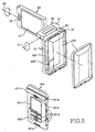
- FIGS. 4 to 8 are perspective views of a portable terminal with a detachable sub-housing according to another embodiment of the present invention. Elements having the same reference numerals as in Figs. 1 - 3 correspond to the elements described with respect to Figs. 1 - 3 and therefore have the same features and characteristics.
- the portable terminal is comprised of the first housing 10, the second housing 20, the hinge housing 30, and a sub-housing 400.
- the sub-housing 400 is detachably installed lengthwise on the first housing 10, for use as a portable video phone, a camera phone, and a camcorder.
- a first in-built battery 500 is provided in the first housing 10 to supply power.
- a cylindrical camera module 401 is installed along the first hinge axis A1 in the sub-housing 400. With the sub-housing 400 combined with the first housing 10, an object can be photographed through a camera lens 401 a in the camera module 401.
- the second housing 20 is connected to the first housing 10 by the hinge housing 30 such that the second housing 20 can rotate about the first hinge axis A1 to an opened or closed state with respect to the first housing 10.
- the pair of hinge arms 31 protrude from both sides of the hinge housing 30 and are combined with the center hinge arm at the upper center of the first housing 10.
- the side hinge arms 31 and the center hinge arm 13 enable the rotation of the second housing 20.
- the hinge housing 30 creates the second hinge axis A2 about which the second housing 20 rotates perpendicularly to the first hinge axis A1.
- the user When the user intends to photograph an object in a narrow space, he removes the sub-housing 400 from the first housing 10 as illustrated in FIGS. 4, 5 and 7.
- Each of the first housing 10 and the sub-housing 400 is provided with a short-range communication module 200 or 300, respectively.
- the short-range communication modules 200 and 300 are activated.
- the short-distance communication modules 200 and 300 are Bluetooth devices that are meant for short-range wireless communication, eliminating cables typically needed to connect such devices.
- the camera module 401 includes the camera lens 401 a at an end and a viewfinder 401 b at the other end.
- the camera module 401 photographs the object and feeds the data of the photographed still image or moving picture to the first housing 10, displaying the data on the LCD 21 of the second housing 20.
- the sub-housing 400 also has a sub-LCD 401c, the still image or moving picture is displayed on the sub-LCD 401c at the same time.
- the user can photograph the object at a desired height and a desired angle in the narrow place, viewing the LCD 21 of the second housing 20 with the first housing 10 held with his one hand and the sub-housing held with his other hand.
- the photographed still image or moving picture is then displayed on the LCD 21.
- a second large-capacity battery 100 is attached to the outer surface of the first housing 10, from which the sub-housing 400 has been removed, as shown in FIG. 5.
- the second battery 100 is removed from the first housing 10 and the sub-housing 400 is attached to the first housing 10. At the same time, the short-range communication modules 200 and 300 are deactivated.
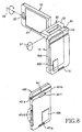
- first and second connectors 15 and 401g are formed in the first housing 10 and sub-housing 400, respectively, as illustrated in FIGS. 7 and 8, as the sub-housing 400 is mounted to the outer surface of the first housing 10, the first connector 15 electrically contact the second connector 401g and thus the short-range communication modules 200 and 300 are turned off.
- the first connector 15 includes a data terminal for data transmission and a power supply terminal for charging the first battery 500 with the second battery 100 and supplying power simultaneously.
- a microphone 401f (FIG. 8) is arranged and at least one operation key 401d is arranged on the outer surface or an edge of the sub-housing 400 to improve digital camera/camcorder functionality as the sub-housing 400 is detached.
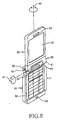
- the portable terminal can function as a mobile phone.
- the sub-housing 400 having the short-range communication module 200 and the camera module 401, is detachably configured, so that improved digital photography can be realized.
Abstract
A portable terminal is disclosed. In the portable terminal, a first housing (10)
extends lengthwise and a hinge housing (30) is installed at an end of the first housing,
for defining a first hinge axis (A1) along a width direction of the first housing and a
second hinge axis (A2) perpendicular to the first hinge axis. A second housing (20) is
connected to the first housing by the hinge housing, for rotating about the first hinge
axis to an opened state or a closed state with respect to the first housing. A subhousing (40)
has a cylindrical camera module (41) along the first hinge axis and is mounted
lengthwise to the outer surface of the first housing.
Description
- The present invention relates generally to a portable terminal, and in particular, to a portable terminal in which a sub-housing has a camera module installed in a direction perpendicular to a lengthwise central axis of a main housing.
- In general, a portable terminal refers to a device by which a user wirelessly communicates with the other party, carrying it. The portable terminal includes HHP (Hand Held Products), CT-2 (Cordless Telephone-2), cellular phones, digital phones, PCS (Personal Communication Service), and PDA (Personal Digital Assistant). They are categorized into a bar type, a flip type, and a folder type according to their outward appearance. The bar type has a single housing shaped like a bar, the flip type has a flip or cover rotatably connected to a bar-type housing by a hinge device, and the folder type has a folder rotatably connected to a bar-type housing by a hinge device.
- Each conventional portable terminal is comprised of an antenna, a data input/output device, and a data transmitter/receiver. The data input/output device is usually a keypad for entering data by finger touch. A touch pad or a touch screen is also used as the data input/output device. A display function is realized by use of an LCD (Liquid Crystal Display) in the data output device. For video calls or photography, a camera lens is used in the portable terminal. Recently, the flip type or the folder type has been popular as a portable terminal focusing on voice or video communication. Due to the advantages of excellent sound sensitivity, small size, and light weight, the flip type and folder type are being widespread. A conventional folder-type portable terminal includes a main body with keys and a microphone, a folder with an LCD and a speaker, and a hinge device for mechanically connecting the main body to the folder such that the folder can rotate upward from the main body. A camera module is installed at a predetermined position of the hinge device, for video call.
- Since a camera lens is fixed to the main body or the hinge device in the conventional portable terminal, the angle of view of the lens is limited to one direction and thus the user must often assume an inconvenient pose in order to photograph an object.
- Moreover, when the camera lens integrated into the conventional portable terminal functions as a camcorder, the object is typically photographed with the main body and the folder positioned at a right angle, and the image is displayed on the LCD of the folder. Since the camera lens is fixed to the main body, the main body and the folder must be moved together to photograph an object. Therefore, it is impossible to photograph the object at an intended height and angle in a narrow place.
- A further shortcoming of the conventional portable terminal is battery capacity, which is insufficient to photograph many still images or to photograph a moving picture for a long time when the portable terminal is used for digital camera/camcorder functionality.
- It is, therefore, an object of the present invention to provide a portable terminal having a camera module installed in a sub-housing, perpendicular to the lengthwise central axis of a main housing in order to improve digital camera/camcorder functionality.
- It is another object of the present invention to provide a portable terminal having a camera module installed in a detachable sub-housing, perpendicular to the lengthwise central axis of a main housing, so that an object can be photographed at a desired height and angle by detaching the sub-housing from the portable terminal.
- It is a further object of the present invention to provide a portable terminal having an in-built battery and a detachable large-capacity battery in order to photograph a moving object for a long time according to the capacities of the batteries.
- The above objects are achieved by a portable terminal according to claim 1. Therein a first housing extends lengthwise, a hinge housing is installed at an end of the first housing, for defining a first hinge axis along the width direction of the first housing and a second hinge axis perpendicular to the first hinge axis, a second housing is connected to the first housing by the hinge housing, for rotating about the first hinge axis to an opened state or a closed state with respect to the first housing, and a sub-housing has a cylindrical camera module along the first hinge axis and is mounted lengthwise to an outer surface of the first housing.
Further advantageous embodiments are according to the dependent claims. - The above and other objects, features and advantages of the present invention will become more apparent from the following detailed description when taken in conjunction with the accompanying drawings in which:
- FIG. 1 is a perspective view of a portable terminal with a second housing closed to a first housing according to an embodiment of the present invention;
- FIG. 2 is a perspective view of the portable terminal with the second housing opened at 90 degrees about a first hinge axis according to the embodiment of the present invention;
- FIG. 3 is a perspective view of the portable terminal with the second housing rotated about a second hinge axis according to the embodiment of the present invention;
- FIG. 4 is a perspective view of a portable terminal with a sub-housing removed from the first housing and thus short-range communication modules activated according to a second embodiment of the present invention;
- FIG. 5 is a perspective view of the portable terminal with the sub-housing removed therefrom and a large-capacity battery attached thereto according to the second embodiment of the present invention;
- FIG. 6 is a perspective view of the portable terminal operating as a mobile phone according to the second embodiment of the present invention;
- FIG. 7 is a perspective view of the portable terminal with the sub-housing removed therefrom to photograph an object according to the second embodiment of the present invention; and
- FIG. 8 is a perspective view of the portable terminal with the sub-housing removed therefrom to photograph an object at a desired height and angle according to the second embodiment of the present invention.
-
- Preferred embodiments of the present invention will be described herein below with reference to the accompanying drawings. In the following description, well-known functions or constructions are not described in detail to avoid obscuring the invention with unnecessary detail.
- Referring to FIGS. 1, 2 and 3, a portable terminal according to an embodiment of the present invention includes a
first housing 10, asecond housing 20, ahinge housing 30, and asub-housing 40. A plurality ofkeys 11 and amicrophone 12 are provided in thefirst housing 10. AnLCD 21 and aspeaker 22 are disposed on thesecond housing 20. Thesecond housing 20 is connected to thefirst housing 10 by thehinge housing 30 such that thesecond housing 20 rotates about a first hinge axis A1 to an opened or closed state with respect to thefirst housing 10. Thehinge housing 30 defines the first hinge axis A1, and a second hinge axis A2 about which thesecond housing 20 rotates perpendicularly to the first hinge axis A1.
Thesub-housing 40 is provided with acamera module 41 at a predetermined position along the first hinge axis A1 to realize video call, camera phone, and camcorder functionalities. Thesub-housing 40 is mounted lengthwise on an outer surface of thefirst housing 10 with the first and second housings having respective inner surfaces that face each other when the portable terminal is in the closed state. A rechargeable built-inbattery 50 is preferably provided in thefirst housing 10 to supply power. Acenter hinge arm 13 is formed at the upper center of thefirst housing 10. A pair of side hingearms 31 protrude from both sides of thehinge housing 30 and are combined with thecenter hinge arm 13, for defining the first hinge axis A1 and rotating thesecond housing 20 about the first hinge axis A1. Atouch pen 60 is inserted into ahole 14 of thefirst housing 10. Aprotrusion 61 is formed at the tip of thetouch pen 60 to be caught at the entrance of thehole 14. - The
camera module 41 includes adigital camera lens 41a at an end and aviewfinder 41b at the other end to allow the user to view a captured object. Asub-LCD 41c is arranged lengthwise in thesub-housing 40. At least oneoperation key 41d is provided in the sub-housing to operate thecamera module 41. Ascroll key 41e is disposed at a predetermined position of the front surface of thesub-housing 40, to select a menu. - The operation of the thus-constituted portable terminal will be described with reference to FIGS. 1, 2 and 3.
- As illustrated in FIG. 1, the portable terminal is comprised of the first and
second housings hinge housing 30, and thesub-housing 40. - In a digital camera/camcorder mode, the
second housing 20 is rotated about the first hinge axis A1 to an open state with respect to thefirst housing 10 and then rotated perpendicularly to the first hinge axis A1, that is, about the second hinge axis A2 with the aid of the side hingearms 31 and thecenter hinge arm 13, such that the user can view theLCD 21. - In this state, the user photographs an object captured using the
camera module 41. Thesub-housing 40 is disposed along the length of thefirst housing 10 and thecamera module 41 is perpendicular to the lengthwise central axis of thefirst housing 10. Since thecamera module 41 has thecamera lens 41a at one end and theviewfinder 41b at the other end, the user captures the object through theviewfinder 41b and photographs the object through thecamera lens 41a. - The photographed still image or moving picture is displayed on the
LCD 21 of thesecond housing 20. - Even if the
second housing 20 is closed to thefirst housing 10 in the reverse order to the above-described procedure, the user can photograph the object through thecamera lens 41a, as viewed through theviewfinder 41b. The photographed still image or moving picture is displayed on thesub-LCD 41c arranged lengthwise in thesub-housing 40.
Meanwhile, the user can take out thetouch pen 60 from thehole 14 of thefirst housing 10 and select between a menu mode and an operation mode by touching the sub-LCD 41c with thetouch pen 60. - In accordance with the first embodiment of the present invention, the digital camera/camcorder functionality is improved by use of the sub-housing 40 with the
camera module 41 perpendicular to the lengthwise central axis of thefirst housing 10. - FIGS. 4 to 8 are perspective views of a portable terminal with a detachable sub-housing according to another embodiment of the present invention. Elements having the same reference numerals as in Figs. 1 - 3 correspond to the elements described with respect to Figs. 1 - 3 and therefore have the same features and characteristics.
- Referring to FIG. 4, the portable terminal is comprised of the
first housing 10, thesecond housing 20, thehinge housing 30, and a sub-housing 400. - The sub-housing 400 is detachably installed lengthwise on the
first housing 10, for use as a portable video phone, a camera phone, and a camcorder. - A first in-built
battery 500 is provided in thefirst housing 10 to supply power. Acylindrical camera module 401 is installed along the first hinge axis A1 in the sub-housing 400. With the sub-housing 400 combined with thefirst housing 10, an object can be photographed through acamera lens 401 a in thecamera module 401. - The
second housing 20 is connected to thefirst housing 10 by thehinge housing 30 such that thesecond housing 20 can rotate about the first hinge axis A1 to an opened or closed state with respect to thefirst housing 10. - The pair of
hinge arms 31 protrude from both sides of thehinge housing 30 and are combined with the center hinge arm at the upper center of thefirst housing 10. The side hingearms 31 and thecenter hinge arm 13 enable the rotation of thesecond housing 20. Thehinge housing 30 creates the second hinge axis A2 about which thesecond housing 20 rotates perpendicularly to the first hinge axis A1. - When the user intends to photograph an object in a narrow space, he removes the sub-housing 400 from the
first housing 10 as illustrated in FIGS. 4, 5 and 7. Each of thefirst housing 10 and the sub-housing 400 is provided with a short-range communication module first housing 10, the short-range communication modules - The short-
distance communication modules - The
camera module 401 includes thecamera lens 401 a at an end and aviewfinder 401 b at the other end. - In this state, the
camera module 401 photographs the object and feeds the data of the photographed still image or moving picture to thefirst housing 10, displaying the data on theLCD 21 of thesecond housing 20. - Since the sub-housing 400 also has a sub-LCD 401c, the still image or moving picture is displayed on the sub-LCD 401c at the same time.
- As illustrated in FIG. 8, the user can photograph the object at a desired height and a desired angle in the narrow place, viewing the
LCD 21 of thesecond housing 20 with thefirst housing 10 held with his one hand and the sub-housing held with his other hand. The photographed still image or moving picture is then displayed on theLCD 21. - If photographing takes time, a second large-capacity battery 100 is attached to the outer surface of the
first housing 10, from which the sub-housing 400 has been removed, as shown in FIG. 5. - With both first and
second batteries 500 and 100 supplying power to thefirst housing 10, long-time digital photographing is possible through the sub-housing 400. - After the photographing is completed, the second battery 100 is removed from the
first housing 10 and the sub-housing 400 is attached to thefirst housing 10. At the same time, the short-range communication modules - Since first and
second connectors first housing 10 andsub-housing 400, respectively, as illustrated in FIGS. 7 and 8, as the sub-housing 400 is mounted to the outer surface of thefirst housing 10, thefirst connector 15 electrically contact thesecond connector 401g and thus the short-range communication modules - The
first connector 15 includes a data terminal for data transmission and a power supply terminal for charging thefirst battery 500 with the second battery 100 and supplying power simultaneously. - At appropriate positions of an outer surface of the sub-housing 400, a
microphone 401f (FIG. 8) is arranged and at least oneoperation key 401d is arranged on the outer surface or an edge of the sub-housing 400 to improve digital camera/camcorder functionality as the sub-housing 400 is detached.
As illustrated in FIG. 6, the portable terminal can function as a mobile phone. - As described above, the sub-housing 400, having the short-
range communication module 200 and thecamera module 401, is detachably configured, so that improved digital photography can be realized. - While the invention has been shown and described with reference to certain preferred embodiments thereof, it will be understood by those skilled in the art that various changes in form and details may be made therein without departing from the spirit and scope of the invention as defined by the appended claims.
Claims (15)
- Portable terminal comprising:a first housing (10);a hinge housing (30)installed at an end of the first housing (10), for defining a first hinge axis (A1) along a width direction of the first housing (10) and a second hinge axis (A2) perpendicular to the first hinge axis;a second housing (20) connected to the first housing (10) by the hinge housing (30), for rotating about the first hinge axis to an opened state or a closed state with respect to the first housing (10); anda sub-housing (40) mounted to an outer surface of the first housing (10) and having a camera module (41) along the first hinge axis (A1).
- Portable terminal of claim 1, further comprising a built-in battery (50) in the first housing (10).
- Portable terminal according to claim 1, wherein the sub-housing (400) with the camera module (401) is detachably mounted to the outer surface of the first housing (10).
- The portable terminal of claim 3, wherein the camera module (401) is installed along the first hinge axis (A1) with the sub-housing mounted to the first housing (10), and can be positioned at a desired height and angle when the sub-housing(400) is removed from the first housing (10).
- The portable terminal of claim 3 or 4, further comprising a built-in battery (500) in the first housing (10), and a detachable large-capacity battery (100) that can be attached to the first housing (10) when the sub-housing (400) is removed.
- The portable terminal of claim 5, wherein the detachable large-capacity battery (100) attaches in a position formerly occupied by the sub-housing (400).
- The portable terminal according to one of claims 3 to 6, wherein the first housing (11) comprises a first short-range communication module (200), and the sub-housing (400) further comprises a second short-range communication module (300), for short-range communication between the first housing (10) and the sub-housing (400).
- Portable terminal according to one of claims 1 to 7, wherein the hinge housing (30) comprises a center hinge arm at the upper center of the first housing (10) and a pair of side hinge arms (31) protruding from both sides of the hinge housing (30) and combined with the center hinge arm (13).
- Portable terminal according to one of claims 1 to 8, further comprising a touch pen (60) having a protrusion (61) at the top end of the touch pen (60), wherein the first housing (10) comprises a hole (14) for receiving the touch pen with the protrusion (61) of the touch pen (60) retained at the entrance of the hole (14).
- Portable terminal according to one of claims 1 to 9, wherein the camera module (41,401) comprises a camera lens (41a,401a) at an end of the camera module (41,401) and a viewfinder (41b,401b) at an other end of the camera module (41,401).
- Portable terminal according to one of claims 1 to 10, wherein the sub-housing (40) further comprises a sub-LCD (41c) and at least one operation key (41d) arranged on an edge of the sub-housing (40).
- Portable terminal of claim 8, wherein the second hinge (20) housing is rotatable about the second hinge axis(A2), with respect to the first housing (10).
- The portable terminal of claim 7, wherein as the sub-housing (400) is removed from the first housing (10), the short-range communication modules (200,300) are activated and as the sub-housing (400) is mounted to the first housing (10), the short-range communication modules (200,300) are deactivated.
- The portable terminal according to one of claims 3 to 6 or 13, wherein the sub-housing (400) further comprises a microphone (401f) positioned on the outer surface of the sub-housing (400).
- The portable terminal according to one of claims 3 to 6 or 13 to 14, wherein the first housing (10) comprises a first connector (15) and the sub-housing (400) further comprises a second connector (401b), for electric connection between the sub-housing (400) and the first housing (10) when the sub-housing (400) is mounted to the first housing (10).
Applications Claiming Priority (2)
| Application Number | Priority Date | Filing Date | Title |
|---|---|---|---|
| KR1020030014151A KR20040079203A (en) | 2003-03-06 | 2003-03-06 | Portable communication device |
| KR2003014151 | 2003-03-06 |
Publications (1)
| Publication Number | Publication Date |
|---|---|
| EP1455505A1 true EP1455505A1 (en) | 2004-09-08 |
Family
ID=32822721
Family Applications (1)
| Application Number | Title | Priority Date | Filing Date |
|---|---|---|---|
| EP04005429A Withdrawn EP1455505A1 (en) | 2003-03-06 | 2004-03-08 | Foldable portable terminal with a camera module |
Country Status (4)
| Country | Link |
|---|---|
| US (1) | US20040209645A1 (en) |
| EP (1) | EP1455505A1 (en) |
| KR (1) | KR20040079203A (en) |
| CN (1) | CN1306784C (en) |
Cited By (11)
| Publication number | Priority date | Publication date | Assignee | Title |
|---|---|---|---|---|
| EP1542434A1 (en) * | 2003-12-09 | 2005-06-15 | Lg Electronics Inc. | Detachable mobile terminal for image communication |
| WO2005119408A1 (en) * | 2004-06-01 | 2005-12-15 | Nokia Corporation | Indication system for use with portable electronic devices |
| WO2006043977A1 (en) * | 2004-10-19 | 2006-04-27 | Sony Ericsson Mobile Communications Ab | Handheld wireless communication device for displaying information on multiple display screens, method of operating the device, and computer program product for operating the device |
| WO2006071414A1 (en) * | 2004-12-23 | 2006-07-06 | Motorola, Inc. | Hinged electronic device with hinged screen |
| US7962854B2 (en) | 2004-10-19 | 2011-06-14 | Sony Ericsson Mobile Communications Ab | Systems, methods and computer program products for displaying content on multiple display screens using handheld wireless communicators |
| US8868222B2 (en) | 2008-06-11 | 2014-10-21 | Nippon Telegraph And Telephone Corporation | Audio quality estimation method, audio quality estimation apparatus, and computer readable recording medium recording a program |
| US9503625B2 (en) | 2013-04-09 | 2016-11-22 | Rui Pedro Oliveira | Attachable smartphone camera |
| USD792497S1 (en) | 2014-04-09 | 2017-07-18 | Rui Pedro Oliveira | Attachable smartphone camera |
| EP3160127A4 (en) * | 2014-06-17 | 2018-02-21 | Sony Corporation | Imaging system, imaging device, information processing device and method, and program |
| EP3691231A1 (en) * | 2019-02-01 | 2020-08-05 | Panasonic Intellectual Property Management Co., Ltd. | Function module |
| WO2021021090A1 (en) * | 2019-07-26 | 2021-02-04 | Hewlett-Packard Development Company, L.P. | Rotatable housing assemblies for cameras and antennas |
Families Citing this family (23)
| Publication number | Priority date | Publication date | Assignee | Title |
|---|---|---|---|---|
| US20040192220A1 (en) * | 2003-03-24 | 2004-09-30 | Inventec Appliances Corp. | Mechanism for switching cellular phone to digital camera |
| KR100566276B1 (en) * | 2003-10-17 | 2006-03-30 | 삼성전자주식회사 | Portable terminal and swing hinge module thereof |
| KR100630067B1 (en) * | 2004-04-29 | 2006-09-27 | 삼성전자주식회사 | Dual hinge type portable communication device with pda |
| JP4778207B2 (en) * | 2004-06-08 | 2011-09-21 | 日本電気株式会社 | HINGE MECHANISM, ELECTRONIC DEVICE INCLUDING THE HINGE MECHANISM, AND METHOD FOR ASSEMBLING THE SAME |
| JP4286735B2 (en) * | 2004-07-08 | 2009-07-01 | シャープ株式会社 | Portable device |
| KR100735266B1 (en) * | 2004-10-26 | 2007-07-03 | 삼성전자주식회사 | Mobile phone for multimedia |
| JP2006135385A (en) * | 2004-11-02 | 2006-05-25 | Canon Inc | Camera |
| TWM268831U (en) | 2004-11-19 | 2005-06-21 | Lite On Technology Corp | Portable electronic apparatus |
| TWM269695U (en) * | 2004-12-22 | 2005-07-01 | Lite On Technology Corp | Hand-held-type electronic data processor |
| US20070060216A1 (en) * | 2005-09-12 | 2007-03-15 | Cheng-Wen Huang | Portable communication apparatus |
| TWI288318B (en) * | 2005-09-14 | 2007-10-11 | Lite On Technology Corp | Portable electronic device |
| JP2007116550A (en) * | 2005-10-21 | 2007-05-10 | Kyocera Corp | Portable terminal device |
| KR100630139B1 (en) * | 2005-11-28 | 2006-10-02 | 삼성전자주식회사 | Portable terminal with dual axis hinge device |
| US8525925B2 (en) | 2008-12-29 | 2013-09-03 | Red.Com, Inc. | Modular digital camera |
| AU2009333038B2 (en) * | 2008-12-29 | 2015-12-17 | Red.Com, Llc | Modular digital camera |
| US8525924B2 (en) | 2008-12-29 | 2013-09-03 | Red.Com, Inc. | Modular motion camera |
| TWI392136B (en) * | 2009-01-06 | 2013-04-01 | Wistron Corp | Tablet personal computer and antenna module thereof |
| KR20110022365A (en) * | 2009-08-27 | 2011-03-07 | 삼성전자주식회사 | Portable terminal with dual axis |
| US9681028B2 (en) | 2013-03-15 | 2017-06-13 | Red.Com, Inc. | Digital camera with wireless connectivity |
| KR20150064955A (en) * | 2013-12-04 | 2015-06-12 | 엘지전자 주식회사 | Mobile terminal |
| ES2748454T3 (en) | 2014-04-04 | 2020-03-16 | Red Com Llc | Diffusion module for digital camera |
| CN203968178U (en) * | 2014-06-25 | 2014-11-26 | 合肥京东方显示光源有限公司 | A kind of device for mobile communication |
| US10116776B2 (en) | 2015-12-14 | 2018-10-30 | Red.Com, Llc | Modular digital camera and cellular phone |
Citations (6)
| Publication number | Priority date | Publication date | Assignee | Title |
|---|---|---|---|---|
| EP0975132A1 (en) * | 1998-07-20 | 2000-01-26 | Alcatel | Telecommunication system comprising at least a mobile phone and at least a camera unit |
| US6115618A (en) * | 1998-02-24 | 2000-09-05 | Motorola, Inc. | Portable electronic device with removable display |
| EP1096771A1 (en) * | 1999-05-06 | 2001-05-02 | Kyocera Corporation | Videophone system using cellular telephone terminal |
| US20010004269A1 (en) * | 1999-12-14 | 2001-06-21 | Junichiro Shibata | Portable terminal |
| US20010043166A1 (en) * | 1996-10-31 | 2001-11-22 | Jeffrey Jacobsen | Color display system for a camera |
| US20020051060A1 (en) * | 2000-05-12 | 2002-05-02 | Jo Wada | Portable terminal unit |
Family Cites Families (8)
| Publication number | Priority date | Publication date | Assignee | Title |
|---|---|---|---|---|
| JPH0822343A (en) * | 1994-07-07 | 1996-01-23 | Olympus Optical Co Ltd | Information processor |
| US6295088B1 (en) * | 1997-02-17 | 2001-09-25 | Nikon Corporation | Portable display device |
| US6397078B1 (en) * | 1999-08-27 | 2002-05-28 | Young S. Kim | Combined mobile telephone and personal digital assistant |
| US6549789B1 (en) * | 2000-04-28 | 2003-04-15 | Motorola Inc. | Portable electronic device with an adaptable user interface |
| JP4578727B2 (en) * | 2001-06-19 | 2010-11-10 | パナソニック株式会社 | Information terminal device provided with camera with rotation function |
| US6985579B2 (en) * | 2001-09-26 | 2006-01-10 | Siemens Communications, Inc. | Portable communication device having an output unit positionable and rotatable with respect to an input unit |
| JP2003152840A (en) * | 2001-11-13 | 2003-05-23 | Nec Corp | Mobile phone |
| JP3882687B2 (en) * | 2002-06-11 | 2007-02-21 | 日本電気株式会社 | Portable communication device |
-
2003
- 2003-03-06 KR KR1020030014151A patent/KR20040079203A/en active Search and Examination
-
2004
- 2004-03-02 US US10/791,564 patent/US20040209645A1/en not_active Abandoned
- 2004-03-05 CN CNB2004100074961A patent/CN1306784C/en not_active Expired - Fee Related
- 2004-03-08 EP EP04005429A patent/EP1455505A1/en not_active Withdrawn
Patent Citations (6)
| Publication number | Priority date | Publication date | Assignee | Title |
|---|---|---|---|---|
| US20010043166A1 (en) * | 1996-10-31 | 2001-11-22 | Jeffrey Jacobsen | Color display system for a camera |
| US6115618A (en) * | 1998-02-24 | 2000-09-05 | Motorola, Inc. | Portable electronic device with removable display |
| EP0975132A1 (en) * | 1998-07-20 | 2000-01-26 | Alcatel | Telecommunication system comprising at least a mobile phone and at least a camera unit |
| EP1096771A1 (en) * | 1999-05-06 | 2001-05-02 | Kyocera Corporation | Videophone system using cellular telephone terminal |
| US20010004269A1 (en) * | 1999-12-14 | 2001-06-21 | Junichiro Shibata | Portable terminal |
| US20020051060A1 (en) * | 2000-05-12 | 2002-05-02 | Jo Wada | Portable terminal unit |
Cited By (14)
| Publication number | Priority date | Publication date | Assignee | Title |
|---|---|---|---|---|
| EP1542434A1 (en) * | 2003-12-09 | 2005-06-15 | Lg Electronics Inc. | Detachable mobile terminal for image communication |
| US7555312B2 (en) | 2003-12-09 | 2009-06-30 | Lg Electronics, Inc. | Detachable mobile terminal for image communication and operating method thereof |
| WO2005119408A1 (en) * | 2004-06-01 | 2005-12-15 | Nokia Corporation | Indication system for use with portable electronic devices |
| WO2006043977A1 (en) * | 2004-10-19 | 2006-04-27 | Sony Ericsson Mobile Communications Ab | Handheld wireless communication device for displaying information on multiple display screens, method of operating the device, and computer program product for operating the device |
| US7962854B2 (en) | 2004-10-19 | 2011-06-14 | Sony Ericsson Mobile Communications Ab | Systems, methods and computer program products for displaying content on multiple display screens using handheld wireless communicators |
| WO2006071414A1 (en) * | 2004-12-23 | 2006-07-06 | Motorola, Inc. | Hinged electronic device with hinged screen |
| US8868222B2 (en) | 2008-06-11 | 2014-10-21 | Nippon Telegraph And Telephone Corporation | Audio quality estimation method, audio quality estimation apparatus, and computer readable recording medium recording a program |
| US9503625B2 (en) | 2013-04-09 | 2016-11-22 | Rui Pedro Oliveira | Attachable smartphone camera |
| US9961243B2 (en) | 2013-04-09 | 2018-05-01 | Rui Pedro Oliveria | Attachable smartphone camera |
| USD792497S1 (en) | 2014-04-09 | 2017-07-18 | Rui Pedro Oliveira | Attachable smartphone camera |
| EP3160127A4 (en) * | 2014-06-17 | 2018-02-21 | Sony Corporation | Imaging system, imaging device, information processing device and method, and program |
| US9973616B2 (en) | 2014-06-17 | 2018-05-15 | Sony Corporation | Imaging system, imaging device, information processing device, method, and program |
| EP3691231A1 (en) * | 2019-02-01 | 2020-08-05 | Panasonic Intellectual Property Management Co., Ltd. | Function module |
| WO2021021090A1 (en) * | 2019-07-26 | 2021-02-04 | Hewlett-Packard Development Company, L.P. | Rotatable housing assemblies for cameras and antennas |
Also Published As
| Publication number | Publication date |
|---|---|
| US20040209645A1 (en) | 2004-10-21 |
| CN1527564A (en) | 2004-09-08 |
| CN1306784C (en) | 2007-03-21 |
| KR20040079203A (en) | 2004-09-14 |
Similar Documents
| Publication | Publication Date | Title |
|---|---|---|
| EP1455505A1 (en) | Foldable portable terminal with a camera module | |
| US7151911B2 (en) | Portable communication device | |
| KR100678189B1 (en) | Portable communication device with tri-cradle function | |
| EP1653713B1 (en) | Portable and foldable communication terminal | |
| US7619686B2 (en) | Apparatus for a combination camcorder-handset device | |
| KR100630098B1 (en) | Portable digital communication device | |
| EP1610530A1 (en) | Dual-axis rotation folder-type portable apparatus | |
| US20070146977A1 (en) | Sliding and folding type portable terminal | |
| US20040203527A1 (en) | Mobile communication terminal with rotational display unit | |
| EP1675362A2 (en) | Foldable phone with a rotatable 3rd housing between the 2 folding housings | |
| EP1667409A1 (en) | Foldable phone with slidable housing to protect display and camera | |
| WO2004066616A1 (en) | Portable device with camera | |
| US7366550B2 (en) | Handheld electronic apparatus | |
| JP4199576B2 (en) | Foldable mobile terminal | |
| US7636590B2 (en) | Self-cradling type portable communication terminal | |
| JP2003018261A (en) | Portable terminal equipment | |
| JP2003283618A (en) | Portable information terminal device with camera | |
| JP4239441B2 (en) | Electronics | |
| JP2002237880A (en) | Cellular phone | |
| KR100497466B1 (en) | Mobile phone having dual camera | |
| KR100531936B1 (en) | Folder type mobile communication terminal having camera | |
| KR100705028B1 (en) | Mobile communication terminal | |
| KR101144521B1 (en) | Mobile phone with two directional self cradling | |
| KR100605492B1 (en) | Folder-type handphone having two folder body on front and back face | |
| KR200340063Y1 (en) | Folder type mobile communication terminal having camera |
Legal Events
| Date | Code | Title | Description |
|---|---|---|---|
| PUAI | Public reference made under article 153(3) epc to a published international application that has entered the european phase |
Free format text: ORIGINAL CODE: 0009012 |
|
| 17P | Request for examination filed |
Effective date: 20040308 |
|
| AK | Designated contracting states |
Kind code of ref document: A1 Designated state(s): AT BE BG CH CY CZ DE DK EE ES FI FR GB GR HU IE IT LI LU MC NL PL PT RO SE SI SK TR |
|
| AX | Request for extension of the european patent |
Extension state: AL LT LV MK |
|
| AKX | Designation fees paid |
Designated state(s): DE FR GB |
|
| 17Q | First examination report despatched |
Effective date: 20060322 |
|
| STAA | Information on the status of an ep patent application or granted ep patent |
Free format text: STATUS: THE APPLICATION IS DEEMED TO BE WITHDRAWN |
|
| 18D | Application deemed to be withdrawn |
Effective date: 20070907 |