EP1453080A1 - Process and composition for removing residues from the microstructure of an object - Google Patents
Process and composition for removing residues from the microstructure of an object Download PDFInfo
- Publication number
- EP1453080A1 EP1453080A1 EP04010688A EP04010688A EP1453080A1 EP 1453080 A1 EP1453080 A1 EP 1453080A1 EP 04010688 A EP04010688 A EP 04010688A EP 04010688 A EP04010688 A EP 04010688A EP 1453080 A1 EP1453080 A1 EP 1453080A1
- Authority
- EP
- European Patent Office
- Prior art keywords
- composition
- carbon dioxide
- residues
- additive
- solvent
- Prior art date
- Legal status (The legal status is an assumption and is not a legal conclusion. Google has not performed a legal analysis and makes no representation as to the accuracy of the status listed.)
- Granted
Links
- 239000000203 mixture Substances 0.000 title claims abstract description 26
- 238000000034 method Methods 0.000 title description 15
- CURLTUGMZLYLDI-UHFFFAOYSA-N Carbon dioxide Chemical compound O=C=O CURLTUGMZLYLDI-UHFFFAOYSA-N 0.000 claims abstract description 104
- 229910002092 carbon dioxide Inorganic materials 0.000 claims abstract description 53
- 239000001569 carbon dioxide Substances 0.000 claims abstract description 51
- 239000000654 additive Substances 0.000 claims abstract description 33
- 230000000996 additive effect Effects 0.000 claims abstract description 25
- 239000006184 cosolvent Substances 0.000 claims abstract description 20
- 239000003112 inhibitor Substances 0.000 claims abstract description 15
- 239000012530 fluid Substances 0.000 claims abstract description 7
- LFQSCWFLJHTTHZ-UHFFFAOYSA-N Ethanol Chemical compound CCO LFQSCWFLJHTTHZ-UHFFFAOYSA-N 0.000 claims description 33
- LYCAIKOWRPUZTN-UHFFFAOYSA-N Ethylene glycol Chemical compound OCCO LYCAIKOWRPUZTN-UHFFFAOYSA-N 0.000 claims description 18
- DNIAPMSPPWPWGF-UHFFFAOYSA-N Propylene glycol Chemical compound CC(O)CO DNIAPMSPPWPWGF-UHFFFAOYSA-N 0.000 claims description 18
- MOVBJUGHBJJKOW-UHFFFAOYSA-N methyl 2-amino-5-methoxybenzoate Chemical compound COC(=O)C1=CC(OC)=CC=C1N MOVBJUGHBJJKOW-UHFFFAOYSA-N 0.000 claims description 16
- 150000005846 sugar alcohols Polymers 0.000 claims description 16
- OKKJLVBELUTLKV-UHFFFAOYSA-N Methanol Chemical compound OC OKKJLVBELUTLKV-UHFFFAOYSA-N 0.000 claims description 15
- 239000008367 deionised water Substances 0.000 claims description 10
- FXHOOIRPVKKKFG-UHFFFAOYSA-N N,N-Dimethylacetamide Chemical compound CN(C)C(C)=O FXHOOIRPVKKKFG-UHFFFAOYSA-N 0.000 claims description 8
- MTHSVFCYNBDYFN-UHFFFAOYSA-N diethylene glycol Chemical compound OCCOCCO MTHSVFCYNBDYFN-UHFFFAOYSA-N 0.000 claims description 6
- 239000002904 solvent Substances 0.000 claims description 6
- SVTBMSDMJJWYQN-UHFFFAOYSA-N 2-methylpentane-2,4-diol Chemical compound CC(O)CC(C)(C)O SVTBMSDMJJWYQN-UHFFFAOYSA-N 0.000 claims description 4
- KFZMGEQAYNKOFK-UHFFFAOYSA-N Isopropanol Chemical compound CC(C)O KFZMGEQAYNKOFK-UHFFFAOYSA-N 0.000 claims description 4
- LRHPLDYGYMQRHN-UHFFFAOYSA-N N-Butanol Chemical compound CCCCO LRHPLDYGYMQRHN-UHFFFAOYSA-N 0.000 claims description 4
- ZXEKIIBDNHEJCQ-UHFFFAOYSA-N isobutanol Chemical compound CC(C)CO ZXEKIIBDNHEJCQ-UHFFFAOYSA-N 0.000 claims description 4
- YPFDHNVEDLHUCE-UHFFFAOYSA-N propane-1,3-diol Chemical compound OCCCO YPFDHNVEDLHUCE-UHFFFAOYSA-N 0.000 claims description 4
- FPGGTKZVZWFYPV-UHFFFAOYSA-M tetrabutylammonium fluoride Chemical compound [F-].CCCC[N+](CCCC)(CCCC)CCCC FPGGTKZVZWFYPV-UHFFFAOYSA-M 0.000 claims description 4
- BYEAHWXPCBROCE-UHFFFAOYSA-N 1,1,1,3,3,3-hexafluoropropan-2-ol Chemical compound FC(F)(F)C(O)C(F)(F)F BYEAHWXPCBROCE-UHFFFAOYSA-N 0.000 claims description 2
- RWLALWYNXFYRGW-UHFFFAOYSA-N 2-Ethyl-1,3-hexanediol Chemical compound CCCC(O)C(CC)CO RWLALWYNXFYRGW-UHFFFAOYSA-N 0.000 claims description 2
- FHCUSSBEGLCCHQ-UHFFFAOYSA-M 2-hydroxyethyl(trimethyl)azanium;fluoride Chemical compound [F-].C[N+](C)(C)CCO FHCUSSBEGLCCHQ-UHFFFAOYSA-M 0.000 claims description 2
- OWBTYPJTUOEWEK-UHFFFAOYSA-N butane-2,3-diol Chemical compound CC(O)C(C)O OWBTYPJTUOEWEK-UHFFFAOYSA-N 0.000 claims description 2
- SZXQTJUDPRGNJN-UHFFFAOYSA-N dipropylene glycol Chemical compound OCCCOCCCO SZXQTJUDPRGNJN-UHFFFAOYSA-N 0.000 claims description 2
- 229940113120 dipropylene glycol Drugs 0.000 claims description 2
- 229960005082 etohexadiol Drugs 0.000 claims description 2
- 229940051250 hexylene glycol Drugs 0.000 claims description 2
- QSUJAUYJBJRLKV-UHFFFAOYSA-M tetraethylazanium;fluoride Chemical compound [F-].CC[N+](CC)(CC)CC QSUJAUYJBJRLKV-UHFFFAOYSA-M 0.000 claims description 2
- POSYVRHKTFDJTR-UHFFFAOYSA-M tetrapropylazanium;fluoride Chemical compound [F-].CCC[N+](CCC)(CCC)CCC POSYVRHKTFDJTR-UHFFFAOYSA-M 0.000 claims description 2
- PUPZLCDOIYMWBV-UHFFFAOYSA-N (+/-)-1,3-Butanediol Chemical compound CC(O)CCO PUPZLCDOIYMWBV-UHFFFAOYSA-N 0.000 claims 2
- WERYXYBDKMZEQL-UHFFFAOYSA-N butane-1,4-diol Chemical compound OCCCCO WERYXYBDKMZEQL-UHFFFAOYSA-N 0.000 claims 2
- BDERNNFJNOPAEC-UHFFFAOYSA-N propan-1-ol Chemical compound CCCO BDERNNFJNOPAEC-UHFFFAOYSA-N 0.000 claims 2
- SBASXUCJHJRPEV-UHFFFAOYSA-N 2-(2-methoxyethoxy)ethanol Chemical compound COCCOCCO SBASXUCJHJRPEV-UHFFFAOYSA-N 0.000 claims 1
- ALQSHHUCVQOPAS-UHFFFAOYSA-N Pentane-1,5-diol Chemical compound OCCCCCO ALQSHHUCVQOPAS-UHFFFAOYSA-N 0.000 claims 1
- BMRWNKZVCUKKSR-UHFFFAOYSA-N butane-1,2-diol Chemical compound CCC(O)CO BMRWNKZVCUKKSR-UHFFFAOYSA-N 0.000 claims 1
- XXJWXESWEXIICW-UHFFFAOYSA-N diethylene glycol monoethyl ether Chemical compound CCOCCOCCO XXJWXESWEXIICW-UHFFFAOYSA-N 0.000 claims 1
- 229940075557 diethylene glycol monoethyl ether Drugs 0.000 claims 1
- 238000004140 cleaning Methods 0.000 description 33
- 239000003153 chemical reaction reagent Substances 0.000 description 21
- 239000000463 material Substances 0.000 description 20
- 235000012431 wafers Nutrition 0.000 description 17
- 230000006378 damage Effects 0.000 description 11
- 239000004065 semiconductor Substances 0.000 description 10
- 150000001875 compounds Chemical class 0.000 description 8
- XLYOFNOQVPJJNP-UHFFFAOYSA-N water Substances O XLYOFNOQVPJJNP-UHFFFAOYSA-N 0.000 description 8
- 150000001298 alcohols Chemical class 0.000 description 7
- ZMXDDKWLCZADIW-UHFFFAOYSA-N N,N-Dimethylformamide Chemical compound CN(C)C=O ZMXDDKWLCZADIW-UHFFFAOYSA-N 0.000 description 5
- 239000003795 chemical substances by application Substances 0.000 description 5
- 238000004519 manufacturing process Methods 0.000 description 5
- 238000011282 treatment Methods 0.000 description 5
- 238000005530 etching Methods 0.000 description 4
- 229940093476 ethylene glycol Drugs 0.000 description 4
- -1 fluoride compound Chemical class 0.000 description 4
- 238000011835 investigation Methods 0.000 description 4
- 239000007788 liquid Substances 0.000 description 4
- 239000006227 byproduct Substances 0.000 description 3
- ZHNUHDYFZUAESO-UHFFFAOYSA-N formamide Substances NC=O ZHNUHDYFZUAESO-UHFFFAOYSA-N 0.000 description 3
- 229960004063 propylene glycol Drugs 0.000 description 3
- 235000013772 propylene glycol Nutrition 0.000 description 3
- 238000003860 storage Methods 0.000 description 3
- CSCPPACGZOOCGX-UHFFFAOYSA-N Acetone Chemical compound CC(C)=O CSCPPACGZOOCGX-UHFFFAOYSA-N 0.000 description 2
- IAZDPXIOMUYVGZ-UHFFFAOYSA-N Dimethylsulphoxide Chemical compound CS(C)=O IAZDPXIOMUYVGZ-UHFFFAOYSA-N 0.000 description 2
- KRHYYFGTRYWZRS-UHFFFAOYSA-M Fluoride anion Chemical compound [F-] KRHYYFGTRYWZRS-UHFFFAOYSA-M 0.000 description 2
- PEDCQBHIVMGVHV-UHFFFAOYSA-N Glycerine Chemical compound OCC(O)CO PEDCQBHIVMGVHV-UHFFFAOYSA-N 0.000 description 2
- ATHHXGZTWNVVOU-UHFFFAOYSA-N N-methylformamide Chemical compound CNC=O ATHHXGZTWNVVOU-UHFFFAOYSA-N 0.000 description 2
- XUIMIQQOPSSXEZ-UHFFFAOYSA-N Silicon Chemical compound [Si] XUIMIQQOPSSXEZ-UHFFFAOYSA-N 0.000 description 2
- 229910052799 carbon Inorganic materials 0.000 description 2
- 230000007423 decrease Effects 0.000 description 2
- 238000001035 drying Methods 0.000 description 2
- 238000011156 evaluation Methods 0.000 description 2
- NBVXSUQYWXRMNV-UHFFFAOYSA-N fluoromethane Chemical compound FC NBVXSUQYWXRMNV-UHFFFAOYSA-N 0.000 description 2
- 239000007789 gas Substances 0.000 description 2
- 238000010438 heat treatment Methods 0.000 description 2
- 238000005259 measurement Methods 0.000 description 2
- VNWKTOKETHGBQD-UHFFFAOYSA-N methane Chemical compound C VNWKTOKETHGBQD-UHFFFAOYSA-N 0.000 description 2
- 238000012986 modification Methods 0.000 description 2
- 230000004048 modification Effects 0.000 description 2
- 230000035515 penetration Effects 0.000 description 2
- 229910052710 silicon Inorganic materials 0.000 description 2
- 239000010703 silicon Substances 0.000 description 2
- ZWVMLYRJXORSEP-UHFFFAOYSA-N 1,2,6-Hexanetriol Chemical compound OCCCCC(O)CO ZWVMLYRJXORSEP-UHFFFAOYSA-N 0.000 description 1
- OKTJSMMVPCPJKN-UHFFFAOYSA-N Carbon Chemical compound [C] OKTJSMMVPCPJKN-UHFFFAOYSA-N 0.000 description 1
- 239000002202 Polyethylene glycol Substances 0.000 description 1
- 238000004380 ashing Methods 0.000 description 1
- QVGXLLKOCUKJST-UHFFFAOYSA-N atomic oxygen Chemical compound [O] QVGXLLKOCUKJST-UHFFFAOYSA-N 0.000 description 1
- 150000007514 bases Chemical class 0.000 description 1
- 239000000919 ceramic Substances 0.000 description 1
- 238000006243 chemical reaction Methods 0.000 description 1
- 239000011248 coating agent Substances 0.000 description 1
- 238000000576 coating method Methods 0.000 description 1
- 239000000356 contaminant Substances 0.000 description 1
- 230000003247 decreasing effect Effects 0.000 description 1
- 238000010586 diagram Methods 0.000 description 1
- 239000006185 dispersion Substances 0.000 description 1
- 238000002474 experimental method Methods 0.000 description 1
- 150000002222 fluorine compounds Chemical class 0.000 description 1
- 239000007792 gaseous phase Substances 0.000 description 1
- 235000011187 glycerol Nutrition 0.000 description 1
- 229960004592 isopropanol Drugs 0.000 description 1
- 238000001459 lithography Methods 0.000 description 1
- 239000002184 metal Substances 0.000 description 1
- FGDYAAXXBPMZDU-UHFFFAOYSA-N n,n-dimethylacetamide;ethanol Chemical compound CCO.CN(C)C(C)=O FGDYAAXXBPMZDU-UHFFFAOYSA-N 0.000 description 1
- 230000003287 optical effect Effects 0.000 description 1
- 229910052760 oxygen Inorganic materials 0.000 description 1
- 239000001301 oxygen Substances 0.000 description 1
- WXZMFSXDPGVJKK-UHFFFAOYSA-N pentaerythritol Chemical compound OCC(CO)(CO)CO WXZMFSXDPGVJKK-UHFFFAOYSA-N 0.000 description 1
- 239000012071 phase Substances 0.000 description 1
- 229920002120 photoresistant polymer Polymers 0.000 description 1
- 239000004033 plastic Substances 0.000 description 1
- 239000002798 polar solvent Substances 0.000 description 1
- 229920001223 polyethylene glycol Polymers 0.000 description 1
- 229920000642 polymer Polymers 0.000 description 1
- 229920001451 polypropylene glycol Polymers 0.000 description 1
- 239000011148 porous material Substances 0.000 description 1
- 239000000047 product Substances 0.000 description 1
- 229920006395 saturated elastomer Polymers 0.000 description 1
- 238000000926 separation method Methods 0.000 description 1
- 239000007787 solid Substances 0.000 description 1
- 239000000126 substance Substances 0.000 description 1
- 239000000758 substrate Substances 0.000 description 1
- 239000004094 surface-active agent Substances 0.000 description 1
- 238000012360 testing method Methods 0.000 description 1
Images

Classifications
-
- H—ELECTRICITY
- H01—ELECTRIC ELEMENTS
- H01L—SEMICONDUCTOR DEVICES NOT COVERED BY CLASS H10
- H01L21/00—Processes or apparatus adapted for the manufacture or treatment of semiconductor or solid state devices or of parts thereof
- H01L21/02—Manufacture or treatment of semiconductor devices or of parts thereof
- H01L21/04—Manufacture or treatment of semiconductor devices or of parts thereof the devices having at least one potential-jump barrier or surface barrier, e.g. PN junction, depletion layer or carrier concentration layer
- H01L21/18—Manufacture or treatment of semiconductor devices or of parts thereof the devices having at least one potential-jump barrier or surface barrier, e.g. PN junction, depletion layer or carrier concentration layer the devices having semiconductor bodies comprising elements of Group IV of the Periodic System or AIIIBV compounds with or without impurities, e.g. doping materials
- H01L21/30—Treatment of semiconductor bodies using processes or apparatus not provided for in groups H01L21/20 - H01L21/26
- H01L21/302—Treatment of semiconductor bodies using processes or apparatus not provided for in groups H01L21/20 - H01L21/26 to change their surface-physical characteristics or shape, e.g. etching, polishing, cutting
- H01L21/304—Mechanical treatment, e.g. grinding, polishing, cutting
-
- C—CHEMISTRY; METALLURGY
- C11—ANIMAL OR VEGETABLE OILS, FATS, FATTY SUBSTANCES OR WAXES; FATTY ACIDS THEREFROM; DETERGENTS; CANDLES
- C11D—DETERGENT COMPOSITIONS; USE OF SINGLE SUBSTANCES AS DETERGENTS; SOAP OR SOAP-MAKING; RESIN SOAPS; RECOVERY OF GLYCEROL
- C11D7/00—Compositions of detergents based essentially on non-surface-active compounds
- C11D7/22—Organic compounds
- C11D7/32—Organic compounds containing nitrogen
- C11D7/3209—Amines or imines with one to four nitrogen atoms; Quaternized amines
-
- B—PERFORMING OPERATIONS; TRANSPORTING
- B08—CLEANING
- B08B—CLEANING IN GENERAL; PREVENTION OF FOULING IN GENERAL
- B08B7/00—Cleaning by methods not provided for in a single other subclass or a single group in this subclass
- B08B7/0021—Cleaning by methods not provided for in a single other subclass or a single group in this subclass by liquid gases or supercritical fluids
-
- C—CHEMISTRY; METALLURGY
- C11—ANIMAL OR VEGETABLE OILS, FATS, FATTY SUBSTANCES OR WAXES; FATTY ACIDS THEREFROM; DETERGENTS; CANDLES
- C11D—DETERGENT COMPOSITIONS; USE OF SINGLE SUBSTANCES AS DETERGENTS; SOAP OR SOAP-MAKING; RESIN SOAPS; RECOVERY OF GLYCEROL
- C11D7/00—Compositions of detergents based essentially on non-surface-active compounds
- C11D7/22—Organic compounds
- C11D7/32—Organic compounds containing nitrogen
-
- C—CHEMISTRY; METALLURGY
- C11—ANIMAL OR VEGETABLE OILS, FATS, FATTY SUBSTANCES OR WAXES; FATTY ACIDS THEREFROM; DETERGENTS; CANDLES
- C11D—DETERGENT COMPOSITIONS; USE OF SINGLE SUBSTANCES AS DETERGENTS; SOAP OR SOAP-MAKING; RESIN SOAPS; RECOVERY OF GLYCEROL
- C11D7/00—Compositions of detergents based essentially on non-surface-active compounds
- C11D7/50—Solvents
- C11D7/5004—Organic solvents
- C11D7/5022—Organic solvents containing oxygen
-
- G—PHYSICS
- G03—PHOTOGRAPHY; CINEMATOGRAPHY; ANALOGOUS TECHNIQUES USING WAVES OTHER THAN OPTICAL WAVES; ELECTROGRAPHY; HOLOGRAPHY
- G03F—PHOTOMECHANICAL PRODUCTION OF TEXTURED OR PATTERNED SURFACES, e.g. FOR PRINTING, FOR PROCESSING OF SEMICONDUCTOR DEVICES; MATERIALS THEREFOR; ORIGINALS THEREFOR; APPARATUS SPECIALLY ADAPTED THEREFOR
- G03F7/00—Photomechanical, e.g. photolithographic, production of textured or patterned surfaces, e.g. printing surfaces; Materials therefor, e.g. comprising photoresists; Apparatus specially adapted therefor
- G03F7/26—Processing photosensitive materials; Apparatus therefor
- G03F7/42—Stripping or agents therefor
- G03F7/422—Stripping or agents therefor using liquids only
- G03F7/425—Stripping or agents therefor using liquids only containing mineral alkaline compounds; containing organic basic compounds, e.g. quaternary ammonium compounds; containing heterocyclic basic compounds containing nitrogen
-
- C11D2111/22—
Definitions
- the present invention relates to a process and a composition for removing residues from the microstructure of an object.
- the present invention specifically relates to a process and a composition for removing residues, such as resists, generated during a semiconductor manufacturing process from a semiconductor wafer surface having a fine structure of convex and concave portions.
- the semiconductor wafer is dipped in an agent, such as a water solution, including a remover to remove residues from the surface of semiconductor wafer.
- an agent such as a water solution
- the present invention is objected to provide a novel and effective cleaning without significant damage to the low-k materials.
- An object of the present invention is, therefore, to provide a process and a composition for effectively removing residues from the microstructure of an object without significant damages to the low-k materials.
- a process for removing residues from the object which comprises steps of preparing a remover including carbon dioxide, an additive for removing the residues, an inhibitor for protecting low-k damage and a co-solvent for dissolving said additive in said carbon dioxide at a pressurized fluid condition, and bringing the object into contact with said remover so as to remove the residues from the object
- a composition is further provided for removing residues from the object, which comprises carbon dioxide, a fluoride containing additive, a co-solvent or mixture of co-solvents capable of dissolving the fluoride containing additive, and an inhibitor.
- the present invention is applied to the microstructure of an object, e.g., a semiconductor wafer having a fine structure of convex and concave portions on its surface, and a substrate made of a metal, plastic or ceramic which forms or remains continuous or non-continuous layer of materials different therefrom.
- an object e.g., a semiconductor wafer having a fine structure of convex and concave portions on its surface, and a substrate made of a metal, plastic or ceramic which forms or remains continuous or non-continuous layer of materials different therefrom.
- said remover used in this invention includescarbon dioxide, an additive for removing the residues, an inhibitor for suppressing residues and a co-solvent for dissolving said additive and said inhibitor in saidcarbon dioxide at a pressurized fluid condition
- the pressurized carbon dioxide has a high dispersion rate and enables the dissolved residues to disperse therein. If carbon dioxide is converted to a supercritical condition, it penetrates into fine pattern portions of the object more effectively.By this feature, the additive is conveyed into pores or concave portions on a surface of the object due to the low viscosity of carbon dioxide.
- the carbon dioxide is pressurized to 5 MPa or more, but not less than 7.1 MPa at a temperature of 31°C to convert the carbon dioxide to a supercritical fluid condition.
- the preferred fluoride compound includes at least one element selected from the group consisting oftetramethylammoniumfluoride, tetraethylammoniumfluoride, tetrapropylammoniumfluoride, tetrabutylammoniumfluoride, cholinefluoride Among these compounds, tetramethylammoniumfluoride (TMAF) is the most preferable one.
- TMAF tetramethylammoniumfluoride
- the concentration of the additive is too low, cleaning of residues is not sufficient.
- the lower limit of the additive is 0.001 wt %, preferably 0.005 wt%, and more preferably 0.01 wt%.
- the concentration is more than 0.1 wt%, low-k materials are damaged because of excessive etching of low-k materials.
- the upper range of the additive is 0.1 wt%, preferably 0.05 wt%, and more preferably 0.03 wt%.
- the remover in the present invention also includespolyhydric alcohol.
- Polyhydric alcohol act as an inhibitor that protects the low-k materials from the significant damage from the additives such as fluorides.
- additives such as fluorides.
- liquid-like residues were recognized as byproducts originated from etching reactions between some of the compounds in the remover and a part of low-k materials. Such byproducts could not be removed and appeared as liquid-like residues because such products from low-k materials were not easily dissolved into supercritical carbon dioxide.
- the remover includes polyhydric alcohols as an inhibitor to protect low-k materials from the damage.
- polyhydric alcohol might adsorb on the surface of the low-k materials and protect the surface from the attack of the chemicals.
- Polyhydric alcohols may be dihydric alcohol such as ethyleneglycol, propyleneglycol, trimethyleneglycol, diethyleneglycol, dipropyleneglycol, 1,2- , 1,3-, 1,4- or 2,3-butanediol, pentamehyleneglycol, hexyleneglycol, octyleneglycol or trihydric alcohols such as glycerin, trimethylolpropanae, 1,2,6-hexanetriol, and tetrahydric alcohols such as pentaerythritol.
- polyethyleneglycol or polypropyleneglycol may be used.
- dihydric alcohols are preferable and ethyleneglycol andpropyleneglycol are more preferable.
- the concentration of the polyhydric alcohols is too low, the protection of the low-k is not sufficient and amount of liquid-like residues increases.
- the lower range of the polyhydric alcohols is 0.005 wt%, preferably 0.007 wt%, and more preferably 0.01 wt%. However, when the concentration is higher than 0.1 wt%, the efficiency of the protection is saturated.
- the upper range of the polyhydric alocholos is 0.1 wt%, preferably 0.07 wt%, and more preferably 0.05 wt%.
- the present invention uses co-solvent to dissolve them into carbon dioxide.
- the co-solvent of the present invention is a compound having an affinity to both carbon dioxide and the additive. Sucha co-solvent dissolves or disperses the additive homogeneously in the pressurized carbon dioxidein fluid condition.
- any co-solvent is used if it can make additives and polyhydric alcohols soluble into pressurized carbon dioxide, alcohols are preferable.
- the alcohol may be any alcohol, e.g.
- ethanol methanol, npropanol, iso-propanol, n-butanol, iso-butanol, diethyleneglycolmonomethyleter, diethyleneglycolmonoethyleter, and hexafluoro isopropanol.
- methanol, ethanol andiso-propanol are preferable because they act as a good co-solvent to wide range of compounds.
- the kind and amount of the co-solvent are selected depending on the kind and amount of the additive to carbon dioxide.
- the amount of the co-solvent is preferably five times or more than that of the additive because the remover easily becomes homogeneous and transparent.
- the remover may include the co-solvent in a range of 1 wt. % to 50 wt. %. If more than 50 wt. % of the co-solvent is added, the penetration rate of the remover decreases due to less amount of carbon dioxide.
- a remover including carbon dioxide, alcohol as the co-solvent, quaternaryammoniumfluoride and/or quaternaryammoniumhydroxide as the additive because these additives are well dissolved in carbon dioxide by alcohol and are CO 2 philic.
- TMAF When TMAF is used as an additive, TMAF should beinitially dissolved into said co-solvent because TMAF is a solid at ambient temperature.
- solvents such as dimethylacetamide (DMAC) or de-ionized water (DIW) could be added to help TMAF to be dissolved into carbon dioxide more easily.
- the amount of such solvents is preferably less than 20 times of TMAF.
- a concentration of DIW should be minimized because of the damages to the low-k materials.
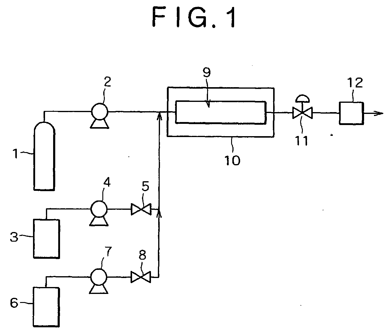
- FIG. 1 shows a simplified schematic drawing of an apparatus use for removing residues according to the present invention.
- 1 is a carbon dioxide cylinder
- 2 is a high pressure pump for carbon dioxide
- 3 is a storage tank of cleaning reagents
- 4 is a pump for cleaning reagents
- 5 is a valve
- 6 is a storage tank for rinse reagents
- 7 is a pump for rinse reagents
- 8 is a valve
- 9 is a high pressure vessel
- 10 is a thermostat.
- the microstructures for example, semiconductor wafer having residues on its surface is introduced to and placed in a high pressure vessel 9, then carbon dioxide is supplied from a carbon dioxide cylinder 1 to the high pressure vessel 9 by a high pressure pump 2.
- the high pressure vessel 9 is thermostated at a specific temperature by a thermostat 10 in order to maintain the pressurized carbon dioxide in the high pressure vessel 9 at the supercritical condition.
- High pressure vessel 9 can be replaced by that having heating unit.
- Cleaning reagents are supplied to the high pressure vessel 9 from tanks 3 by high pressure pumps 4. Cleaning step starts at the time when the cleaning reagents are fed from tank 3 to the high pressure vessel 9.
- the feed of the carbon dioxide and cleaning reagents may be continuous or batch-like.
- the removing process is performed at a temperature in the range from 31°C to 120°C, and at a pressure ranged from 5 M Pa to 30 M Pa, preferably, from 7.1 M Pa to 20 M Pa.
- the time required for removing the residues depends on the size of the object, the kind and amount of the residues, which is usually in the range from a minute to several ten minutes.
- a rinse step follows. Residues removed from surface during the cleaning step remains in the vessel 9 after the cleaning step finishes. If pure carbon dioxide is fed into such conditions, some portion of residues will deposit on the surface of the objects. Therefore, after the cleaning step, the first rinse step with the mixture of carbon dioxide and rinse agents is applied. After this first rinse step, the second rinse step with pure carbon dioxide is applied.
- Preferable rinse agents used in the first rinse step are those that can remove liquid-like residues.
- compounds having specific dielectric constant similar to water are effective for this purpose. Since the specific dielectric constant of water is 78 at 25 °C under atmospheric pressure, compounds having specific dielectric constant not smaller than 78 are used. The reason why the required specific dielectric constants are similar to that of water is that the liquid-like residues as byproducts of low-k etching have high polarity, resulting in the high affinity to the polar solvents.
- polyhydric alcohols are required in the present invention as described in the previous section.
- rinse agent having specific dielectric constant not smaller than 78 may be used with a relative longer treatment time without any addition of polyhydric alcohols in the cleaning step.
- the process time of the first rinse step for example, 5 min. or less
- the first rinse step can be done by stopping the feed of the cleaning reagents by the valve 5, followed by feed of carbon dioxide and rinse reagents to the high pressure vessel 9 to get rid of the contents of vessel 9.
- a flow meter 12 may be used to control the flow rate.
- Fluid evacuated from the cleaning step and the first rinse step can be recycled and re-used by the separation into gaseous carbon dioxide and liquid fractions by a carbon dioxide recycle process, for example, including a liquid gas separator.
- etch rate measurements of low-k films were carried out.
- Low-k films were prepared on the silicon wafer by coating the materials consisting of organic silicon followed by heating and drying.
- the film thickness of the low-k films was about 5000 ⁇ and k-value was in the range of 2 to 3.
- a wafer coated by the low-k film was set into the high pressure vessel 9. After closing the cover of the vessel 9, carbon dioxide was introduced from carbon dioxide cylinder 1 through the pump 2.
- the temperature of the vessel 9 was maintained at 50°C with a thermostat 10 and the pressure was controlled by the control valve 11.
- a rinse reagent used in the first rinse step was 0.5 wt% of de-ionized water, 4.5 wt % of ethanol and 95wt% of carbon dioxide.
- Etch rates were calculated by the difference in the film thickness before and after the treatment divided by the 10 min. Film thickness was measured by an optical measurement tool. The results are shown in table 1.
- wafers coated by the low-k film were prepared. After line and space patterns (180 nm width) were processed by the lithography on the surface, ordinary etching by fluorocarbon gases and ashing by oxygen plasma. After one minute cleaning with cleaning reagents listed in the table 2 under the same condition as the example 1, five minute or ten minute of the first rinse step using components listed in table 2, followed by ten minutes of the second rinse step with a pure carbon dioxide.
- the first rinse reagents used were 0.5 wt% of listed components, 4.5 wt% of ethanol and 95 wt% of carbon dioxide. After the release of the pressure by opening the pressure control valve 11, the treated wafer was taken and provided for the evaluation.
- the cleaning performance was evaluated by the observation of a scanning electron microscope (SEM) with amplitude of 50000. The performance was checked both residues on the surface of the line and the liquid-like residues. The criteria used for investigation was as follows; Excellent: No residues remained Good: Amount of residues was less than 1 area % on the patterned side of the wafer. NG (Not good): Amount of residues was more than 1 area %.
- the cleaning process described in the present invention provides one of the optimized cleaning processes applicable to the microstructure such as semiconductor wafers.
Abstract
Description
- The present invention relates to a process and a composition for removing residues from the microstructure of an object. The present invention specifically relates to a process and a composition for removing residues, such as resists, generated during a semiconductor manufacturing process from a semiconductor wafer surface having a fine structure of convex and concave portions.
- It is required as one step in manufacturing a semiconductor wafer to remove residues, such as photoresists, UV-hardened resists, X-ray hardened resists, ashed resists, carbon-fluorine containing polymer, plasma etch residues, and organic or inorganic contaminants from the other steps of the manufacturing process. The dry and wet removal methods are commonly used In the wet removal method, the semiconductor wafer is dipped in an agent, such as a water solution, including a remover to remove residues from the surface of semiconductor wafer.
- Recently, supercritical carbon dioxide isused as such an agent because of its low viscosity and high diffusivity. According to such properties, cleaning with supercritical carbon dioxide provides several advances in the treatment of microstructures, such as high penetration into small areas between microstructures and successfully drying microstructures because of non liquid-liquid interface in the supercritical phase.
- However, supercritical carbon dioxide is not enough by itself to remove several residues from the surface of the semiconductor wafer. To resolve this problem, several additives to supercritical carbon dioxide are proposed. As described in the Japanese unexamined patent publication No. 10-125644, methane or surfactant having CFx group is used as an additive to supercritical carbon dioxide. In Japanese unexamined patent publication No. 8-191063, dimethylsulfoxide ordimethyl-formamide is used as suchan additive. However, based on the inventors' studies, these additives are not always effective for removing residues. Especially, when the cleaning object is like a wafer which consists of low dielectric constant materials, the quality of such wafer decreased after treatments by such process using alkaline compounds and water. This might be occurred because basic compounds and water caused damages on low dielectric constant materials, especially on materials having dielectric constant lower than 4. (hereinafter referred to as low-k materials) Thus, the present invention is objected to provide a novel and effective cleaning without significant damage to the low-k materials.
- An object of the present invention is, therefore, to provide a process and a composition for effectively removing residues from the microstructure of an object without significant damages to the low-k materials.
- According to the present invention, a process is provided for removing residues from the object, which comprises steps of preparing a remover including carbon dioxide, an additive for removing the residues, an inhibitor for protecting low-k damage and a co-solvent for dissolving said additive in said carbon dioxide at a pressurized fluid condition, and bringing the object into contact with said remover so as to remove the residues from the object
- A composition is further provided for removing residues from the object, which comprises carbon dioxide, a fluoride containing additive, a co-solvent or mixture of co-solvents capable of dissolving the fluoride containing additive, and an inhibitor.
- The foregoing and additional features and characteristics of the present invention will become more apparent from the following detailed description considered with reference to the accompanying drawings in which like reference numerals designate like elements and wherein:
- FIG. 1 is a schematic diagram of an apparatus for removing residues in accordance with the present invention.
-
- The present invention is applied to the microstructure of an object, e.g., a semiconductor wafer having a fine structure of convex and concave portions on its surface, and a substrate made of a metal, plastic or ceramic which forms or remains continuous or non-continuous layer of materials different therefrom.
- First, said remover used in this invention is described. It includescarbon dioxide, an additive for removing the residues, an inhibitor for suppressing residues and a co-solvent for dissolving said additive and said inhibitor in saidcarbon dioxide at a pressurized fluid condition
The pressurized carbon dioxide has a high dispersion rate and enables the dissolved residues to disperse therein. If carbon dioxide is converted to a supercritical condition, it penetrates into fine pattern portions of the object more effectively.By this feature, the additive is conveyed into pores or concave portions on a surface of the object due to the low viscosity of carbon dioxide. The carbon dioxide is pressurized to 5 MPa or more, but not less than 7.1 MPa at a temperature of 31°C to convert the carbon dioxide to a supercritical fluid condition. - Although any additives that can remove residues from microstructures could be used, it is preferred in the present invention to use quaternaryammoniumfluorides because of their effective cleaning ability. The preferred fluoride compound includes at least one element selected from the group consisting oftetramethylammoniumfluoride, tetraethylammoniumfluoride, tetrapropylammoniumfluoride, tetrabutylammoniumfluoride, cholinefluoride Among these compounds, tetramethylammoniumfluoride (TMAF) is the most preferable one.
- If the concentration of the additive is too low, cleaning of residues is not sufficient. The lower limit of the additive is 0.001 wt %, preferably 0.005 wt%, and more preferably 0.01 wt%. However, when the concentration is more than 0.1 wt%, low-k materials are damaged because of excessive etching of low-k materials. Thus, the upper range of the additive is 0.1 wt%, preferably 0.05 wt%, and more preferably 0.03 wt%.
- The remover in the present invention also includespolyhydric alcohol. Polyhydric alcohol act as an inhibitor that protects the low-k materials from the significant damage from the additives such as fluorides. During inventors' studies, after some cleaning tests of microstructures containing of low-k films, there were some liquid-like residues. These 'liquid like residues' were recognized as byproducts originated from etching reactions between some of the compounds in the remover and a part of low-k materials. Such byproducts could not be removed and appeared as liquid-like residues because such products from low-k materials were not easily dissolved into supercritical carbon dioxide.
- By further investigations, it was found that the amount of such liquid-like residues could be reduced when polyhydric alcohols were used as a component of said remover. Therefore, in the present invention, the remover includes polyhydric alcohols as an inhibitor to protect low-k materials from the damage. Although the mechanism of the protection of low-k by polyhydric alcohol is still under investigations,polyhydric alcohol might adsorb on the surface of the low-k materials and protect the surface from the attack of the chemicals.
- Polyhydric alcohols may be dihydric alcohol such as ethyleneglycol, propyleneglycol, trimethyleneglycol, diethyleneglycol, dipropyleneglycol, 1,2- , 1,3-, 1,4- or 2,3-butanediol, pentamehyleneglycol, hexyleneglycol, octyleneglycol or trihydric alcohols such as glycerin, trimethylolpropanae, 1,2,6-hexanetriol, and tetrahydric alcohols such as pentaerythritol. Also, polyethyleneglycol or polypropyleneglycol may be used. Among these compounds, dihydric alcohols are preferable and ethyleneglycol andpropyleneglycol are more preferable.
- If the concentration of the polyhydric alcohols is too low, the protection of the low-k is not sufficient and amount of liquid-like residues increases. The lower range of the polyhydric alcohols is 0.005 wt%, preferably 0.007 wt%, and more preferably 0.01 wt%. However, when the concentration is higher than 0.1 wt%, the efficiency of the protection is saturated. Thus, the upper range of the polyhydric alocholos is 0.1 wt%, preferably 0.07 wt%, and more preferably 0.05 wt%.
- As the pressurized carbon dioxide is not enough by itself to dissolve additives and inhibitors such as TMAF andpolyhydric alcohols, the present invention uses co-solvent to dissolve them into carbon dioxide. The co-solvent of the present invention is a compound having an affinity to both carbon dioxide and the additive. Sucha co-solvent dissolves or disperses the additive homogeneously in the pressurized carbon dioxidein fluid condition. Although any co-solvent is used if it can make additives and polyhydric alcohols soluble into pressurized carbon dioxide, alcohols are preferable. The alcohol may be any alcohol, e.g. ethanol, methanol, npropanol, iso-propanol, n-butanol, iso-butanol, diethyleneglycolmonomethyleter, diethyleneglycolmonoethyleter, and hexafluoro isopropanol. Among these alcohols, methanol, ethanol andiso-propanol are preferable because they act as a good co-solvent to wide range of compounds.
- The kind and amount of the co-solvent are selected depending on the kind and amount of the additive to carbon dioxide. The amount of the co-solvent is preferably five times or more than that of the additive because the remover easily becomes homogeneous and transparent. Alternatively, the remover may include the co-solvent in a range of 1 wt. % to 50 wt. %. If more than 50 wt. % of the co-solvent is added, the penetration rate of the remover decreases due to less amount of carbon dioxide. It is preferable to use a remover including carbon dioxide, alcohol as the co-solvent, quaternaryammoniumfluoride and/or quaternaryammoniumhydroxide as the additive because these additives are well dissolved in carbon dioxide by alcohol and are CO2 philic.
- When TMAF is used as an additive, TMAF should beinitially dissolved into said co-solvent because TMAF is a solid at ambient temperature. At this time, solvents such as dimethylacetamide (DMAC) or de-ionized water (DIW) could be added to help TMAF to be dissolved into carbon dioxide more easily. The amount of such solvents is preferably less than 20 times of TMAF. Especially, a concentration of DIW should be minimized because of the damages to the low-k materials.
- The practical procedure will be described using drawings. In the below description, components of remover other than carbon dioxide, a mixture of additives, inhibitors,co-solvents is simply called 'cleaning reagents'. Figure 1 shows a simplified schematic drawing of an apparatus use for removing residues according to the present invention. In the figure, 1 is a carbon dioxide cylinder, 2 is a high pressure pump for carbon dioxide, 3 is a storage tank of cleaning reagents, 4 is a pump for cleaning reagents, 5 is a valve, 6 is a storage tank for rinse reagents, 7 is a pump for rinse reagents, 8 is a valve, 9 is a high pressure vessel, and 10 is a thermostat. Firstly, the microstructures, for example, semiconductor wafer having residues on its surface is introduced to and placed in a
high pressure vessel 9, then carbon dioxide is supplied from acarbon dioxide cylinder 1 to thehigh pressure vessel 9 by ahigh pressure pump 2. Thehigh pressure vessel 9 is thermostated at a specific temperature by athermostat 10 in order to maintain the pressurized carbon dioxide in thehigh pressure vessel 9 at the supercritical condition.High pressure vessel 9 can be replaced by that having heating unit. Cleaning reagents are supplied to thehigh pressure vessel 9 fromtanks 3 by high pressure pumps 4. Cleaning step starts at the time when the cleaning reagents are fed fromtank 3 to thehigh pressure vessel 9. The feed of the carbon dioxide and cleaning reagents may be continuous or batch-like. - The removing process is performed at a temperature in the range from 31°C to 120°C, and at a pressure ranged from 5 M Pa to 30 M Pa, preferably, from 7.1 M Pa to 20 M Pa. The time required for removing the residues depends on the size of the object, the kind and amount of the residues, which is usually in the range from a minute to several ten minutes.
- After a cleaning step, a rinse step follows. Residues removed from surface during the cleaning step remains in the
vessel 9 after the cleaning step finishes. If pure carbon dioxide is fed into such conditions, some portion of residues will deposit on the surface of the objects. Therefore, after the cleaning step, the first rinse step with the mixture of carbon dioxide and rinse agents is applied. After this first rinse step, the second rinse step with pure carbon dioxide is applied. - Preferable rinse agents used in the first rinse step are those that can remove liquid-like residues. After invertors' investigations, compounds having specific dielectric constant similar to water are effective for this purpose. Since the specific dielectric constant of water is 78 at 25 °C under atmospheric pressure, compounds having specific dielectric constant not smaller than 78 are used. The reason why the required specific dielectric constants are similar to that of water is that the liquid-like residues as byproducts of low-k etching have high polarity, resulting in the high affinity to the polar solvents.
- On the other hand, polyhydric alcohols are required in the present invention as described in the previous section. However, if the amount of the cleaning reagents is small enough to suppress the by-production due to damages of low-k materials, rinse agent having specific dielectric constant not smaller than 78 may be used with a relative longer treatment time without any addition of polyhydric alcohols in the cleaning step. However, in order to minimize the process time of the first rinse step (for example, 5 min. or less), it is preferable to minimize the by-production of liquid-like residues with addition of polyhydric alcohols.
- Practically, the first rinse step can be done by stopping the feed of the cleaning reagents by the
valve 5, followed by feed of carbon dioxide and rinse reagents to thehigh pressure vessel 9 to get rid of the contents ofvessel 9. Aflow meter 12 may be used to control the flow rate. During the first rinse step, it is preferable to decrease the feed rate of rinse reagents gradually or in a stepwise manner withvalve 8 to replace the contents by pure carbon dioxide, followed by the second rinse step with pure carbon dioxide. - Fluid evacuated from the cleaning step and the first rinse step can be recycled and re-used by the separation into gaseous carbon dioxide and liquid fractions by a carbon dioxide recycle process, for example, including a liquid gas separator.
- After the second rinse step, by releasing pressure with a
pressure control valve 11, carbon dioxide vaporize to gaseous phase. Therefore, microstructures such as semiconductor wafers can be dried without any water mark and any destructions of the pattern. - Hereinafter, the present invention is described with reference to experiments. Although the present invention has been fully described by way of example with reference to the accompanying drawings, it is to be understood that various changes and modifications will beapparent to those skilled in the art. Therefore, unless otherwise such changes and modifications depart from the scope of the present invention, they should be construed as being included therein.
- At first, in order to investigate the degree of the damage of cleaning reagent to the low-k materials, etch rate measurements of low-k films were carried out. Low-k films were prepared on the silicon wafer by coating the materials consisting of organic silicon followed by heating and drying. The film thickness of the low-k films was about 5000Å and k-value was in the range of 2 to 3. Using cleaning tools shown in the figure 1, a wafer coated by the low-k film was set into the
high pressure vessel 9. After closing the cover of thevessel 9, carbon dioxide was introduced fromcarbon dioxide cylinder 1 through thepump 2. The temperature of thevessel 9 was maintained at 50°C with athermostat 10 and the pressure was controlled by thecontrol valve 11. After the pressure reached 15 MPa, cleaning reagents were fed into thevessel 9 from thestorage tank 4 through thepump 4. After a 10 minute-treatment, 5 minutes of the first rinse step was applied, followed by 10 minutes of the second rinse step with a pure carbon dioxide. A rinse reagent used in the first rinse step was 0.5 wt% of de-ionized water, 4.5 wt % of ethanol and 95wt% of carbon dioxide. - After the second rinse step, the pressure was released by the
pressure control valve 11 and wafer was taken to be provided for further evaluation. Etch rates (Å/min) were calculated by the difference in the film thickness before and after the treatment divided by the 10 min. Film thickness was measured by an optical measurement tool. The results are shown in table 1. - The abbreviation used in table 1 are follows;
TMAF:Tetramethylammoniumfluoride, DMAC:Dimethylacetamide, DIW:de-ionized water, EG:Ethyleneglycol, PG:Propyleneglycol, EtOH:EthanolRun - Componets of remover Etch rate Å/min CO2 Additve and inhibitor Co-solvent Additional solvents TMAF EG PG EtOH DMAC DIW 1 95 0.013 0 0 4.9 0.063 0.024 240 2 95 0.013 0.012 0 4.9 0.051 0.024 230 3 95 0.013 0 0.012 4.9 0.063 0.024 155 4 95 0.013 0 0.024 4.9 0.051 0.024 148 5 95 0.005 0 0 5.1 0.066 0 53 6 95 0.005 0 0.012 4.9 0.054 0 19 7 95 0.013 0 0 4.8 0.165 0 91 8 95 0.013 0 0.03 4.8 0.135 0 67 - In the same manner described in the example 1, wafers coated by the low-k film were prepared. After line and space patterns (180 nm width) were processed by the lithography on the surface, ordinary etching by fluorocarbon gases and ashing by oxygen plasma. After one minute cleaning with cleaning reagents listed in the table 2 under the same condition as the example 1, five minute or ten minute of the first rinse step using components listed in table 2, followed by ten minutes of the second rinse step with a pure carbon dioxide. The first rinse reagents used were 0.5 wt% of listed components, 4.5 wt% of ethanol and 95 wt% of carbon dioxide. After the release of the pressure by opening the
pressure control valve 11, the treated wafer was taken and provided for the evaluation. The cleaning performance was evaluated by the observation of a scanning electron microscope (SEM) with amplitude of 50000. The performance was checked both residues on the surface of the line and the liquid-like residues. The criteria used for investigation was as follows;
Excellent: No residues remained
Good: Amount of residues was less than 1 area % on the patterned side of the wafer.
NG (Not good): Amount of residues was more than 1 area %. - The abbreviation used in table 2 are follows;
TMAF:Tetramethylammoniumfluoride, DMAC:Dimethylacetamide, H2O:water (ε=78), DIW:de-ionized water, EG:Ethyleneglycol, PG:Propyleneglycol, EtOH:Ethanol, FA:Formamide (ε=111), MF:Methylformamide (ε=182), DMF:Dimethylformamide (ε=36.7), MeOH:Methanol (ε=42), AC:Acetone (ε=21) - According to the cleaning process described in the present invention, low-k materials that are easily damaged by the cleaning reagents could be protected by the use of the cleaning reagents including inhibitors such aspolyhydric alcohols added into carbon dioxide. Besides, residues produced because of the damages of low-k materials by the cleaning reagents could be removed by a suitable selection of the rinse reagents. Therefore, the cleaning process described in the present invention provides one of the optimized cleaning processes applicable to the microstructure such as semiconductor wafers.

Claims (16)
- A composition for removing residues from the microstructure of an object comprising:carbon dioxide;an additive for removing the residues;an inhibitor for suppressing residues; anda co-solvent for dissolving said additive and said inhibitor in said carbon dioxide at a pressurized fluid condition.
- The composition of claim 1 wherein the additive comprises a quaternaryammoniumfluoride.
- The composition of claim 2 wherein the quaternaryammoniumfluoride is at least one selected from the group consisting of tetramethylammoniumfluoride, tetraethylammoniumfluoride, tetrapropylammoniumfluoride, tetrabutylammoniumfluoride and choline fluoride.
- The composition of claim 3 wherein the quaternaryammoniumfluoride is tetramethylammoniumfluoride.
- The composition of claim 2 wherein the additive further comprises a quaternaryammoniumhydroxide.
- The composition of anyone of claims 1 to 5 wherein the concentration of the additive ranges from 0.001 to 0.1 weight percent.
- The composition of anyone of claims 1 to 6 wherein the inhibitor comprises a polyhydric alcohol.
- The composition of claim 7 wherein the concentration of the polyhydric alcohol ranges from 0.005 to 0.1 weight percent.
- The composition of claim 7 or 8 wherein the polyhydric alcohol is selected from a dihydric alcohol, a trihydric alcohol or a tetrahydric alcohol.
- The composition of claim 9 wherein the polyhydric alcohol is a dihydric alcohol.
- The composition of claim 10 wherein the dihydric alcohol is selected from ethylene glycol, propylene glycol, trimethyleneglycol, diethyleneglycol, dipropyleneglycol, 1,2-butanediol, 1,3-butanediol, 1,4-butanediol, 2,3-butanediol, pentamethyleneglycol, hexyleneglycol or octyleneglycol.
- The composition of claim 11 wherein the dihydric alcohol is selected from ethylene glycol or propylene glycol.
- The composition of anyone of claims 1 to 12 wherein the co-solvent is selected from ethanol, methanol, n-propanol, isopropanol, n-butanol, isobutanol, diethyleneglycolmonomethylether, diethyleneglycolmonoethylether, hexafluoroisopropanol or mixtures thereof.
- The composition of claim 13 wherein the co-solvent comprises an additional solvent selected from dimethylacetamide or de-ionized water.
- The composition of claim 13 or 14 wherein the concentration of the co-solvent ranges from 1 to 50 weight percent.
- The composition according to anyone of the preceding claims, comprising carbon dioxide, tetramethylammoniumfluoride, ethanol, dimethylacetamide and propylene glycol.
Applications Claiming Priority (3)
| Application Number | Priority Date | Filing Date | Title |
|---|---|---|---|
| US10/152,782 US20030217764A1 (en) | 2002-05-23 | 2002-05-23 | Process and composition for removing residues from the microstructure of an object |
| US152782 | 2002-05-23 | ||
| EP03011130A EP1365441B1 (en) | 2002-05-23 | 2003-05-22 | Process and composition for removing residues from the microstructure of an object |
Related Parent Applications (1)
| Application Number | Title | Priority Date | Filing Date |
|---|---|---|---|
| EP03011130A Division EP1365441B1 (en) | 2002-05-23 | 2003-05-22 | Process and composition for removing residues from the microstructure of an object |
Publications (2)
| Publication Number | Publication Date |
|---|---|
| EP1453080A1 true EP1453080A1 (en) | 2004-09-01 |
| EP1453080B1 EP1453080B1 (en) | 2006-07-05 |
Family
ID=29400523
Family Applications (2)
| Application Number | Title | Priority Date | Filing Date |
|---|---|---|---|
| EP03011130A Expired - Lifetime EP1365441B1 (en) | 2002-05-23 | 2003-05-22 | Process and composition for removing residues from the microstructure of an object |
| EP04010688A Expired - Fee Related EP1453080B1 (en) | 2002-05-23 | 2003-05-22 | Process and composition for removing residues from the microstructure of an object |
Family Applications Before (1)
| Application Number | Title | Priority Date | Filing Date |
|---|---|---|---|
| EP03011130A Expired - Lifetime EP1365441B1 (en) | 2002-05-23 | 2003-05-22 | Process and composition for removing residues from the microstructure of an object |
Country Status (9)
| Country | Link |
|---|---|
| US (2) | US20030217764A1 (en) |
| EP (2) | EP1365441B1 (en) |
| JP (2) | JP4256722B2 (en) |
| KR (2) | KR100562597B1 (en) |
| CN (2) | CN1563315A (en) |
| AT (1) | ATE322740T1 (en) |
| DE (2) | DE60306617T2 (en) |
| SG (1) | SG128463A1 (en) |
| TW (2) | TWI249573B (en) |
Cited By (1)
| Publication number | Priority date | Publication date | Assignee | Title |
|---|---|---|---|---|
| EP1572833A1 (en) * | 2002-10-31 | 2005-09-14 | Advanced Technology Materials, Inc. | Supercritical carbon dioxide/chemical formulation for ashed and unashed aluminum post-etch residue removal |
Families Citing this family (34)
| Publication number | Priority date | Publication date | Assignee | Title |
|---|---|---|---|---|
| US7064070B2 (en) * | 1998-09-28 | 2006-06-20 | Tokyo Electron Limited | Removal of CMP and post-CMP residue from semiconductors using supercritical carbon dioxide process |
| IL152376A0 (en) * | 2000-04-25 | 2003-05-29 | Tokyo Electron Ltd | Method of depositing metal film and metal deposition cluster tool including supercritical drying/cleaning module |
| JP2002237481A (en) * | 2001-02-09 | 2002-08-23 | Kobe Steel Ltd | Method of cleaning microscopic structure |
| JP3978023B2 (en) * | 2001-12-03 | 2007-09-19 | 株式会社神戸製鋼所 | High pressure processing method |
| WO2003070846A2 (en) * | 2002-02-15 | 2003-08-28 | Supercritical Systems Inc. | Drying resist with a solvent bath and supercritical co2 |
| AU2003220039A1 (en) * | 2002-03-04 | 2003-09-22 | Supercritical Systems Inc. | Method of passivating of low dielectric materials in wafer processing |
| AU2003220443A1 (en) * | 2002-03-22 | 2003-10-13 | Supercritical Systems Inc. | Removal of contaminants using supercritical processing |
| US7169540B2 (en) * | 2002-04-12 | 2007-01-30 | Tokyo Electron Limited | Method of treatment of porous dielectric films to reduce damage during cleaning |
| US20030217764A1 (en) * | 2002-05-23 | 2003-11-27 | Kaoru Masuda | Process and composition for removing residues from the microstructure of an object |
| US20060019850A1 (en) * | 2002-10-31 | 2006-01-26 | Korzenski Michael B | Removal of particle contamination on a patterned silicon/silicon dioxide using dense fluid/chemical formulations |
| US7011716B2 (en) * | 2003-04-29 | 2006-03-14 | Advanced Technology Materials, Inc. | Compositions and methods for drying patterned wafers during manufacture of integrated circuitry products |
| US20040177867A1 (en) * | 2002-12-16 | 2004-09-16 | Supercritical Systems, Inc. | Tetra-organic ammonium fluoride and HF in supercritical fluid for photoresist and residue removal |
| US20040231707A1 (en) * | 2003-05-20 | 2004-11-25 | Paul Schilling | Decontamination of supercritical wafer processing equipment |
| US20050022850A1 (en) * | 2003-07-29 | 2005-02-03 | Supercritical Systems, Inc. | Regulation of flow of processing chemistry only into a processing chamber |
| US20050227482A1 (en) * | 2004-03-24 | 2005-10-13 | Korzenski Michael B | Composition useful for removal of bottom anti-reflection coatings from patterned ion-implanted photoresist wafers |
| US7195676B2 (en) * | 2004-07-13 | 2007-03-27 | Air Products And Chemicals, Inc. | Method for removal of flux and other residue in dense fluid systems |
| US20060081273A1 (en) * | 2004-10-20 | 2006-04-20 | Mcdermott Wayne T | Dense fluid compositions and processes using same for article treatment and residue removal |
| US7550075B2 (en) * | 2005-03-23 | 2009-06-23 | Tokyo Electron Ltd. | Removal of contaminants from a fluid |
| US20060219268A1 (en) * | 2005-03-30 | 2006-10-05 | Gunilla Jacobson | Neutralization of systemic poisoning in wafer processing |
| US7253253B2 (en) * | 2005-04-01 | 2007-08-07 | Honeywell Federal Manufacturing & Technology, Llc | Method of removing contaminants from plastic resins |
| US20070012337A1 (en) * | 2005-07-15 | 2007-01-18 | Tokyo Electron Limited | In-line metrology for supercritical fluid processing |
| US7314828B2 (en) * | 2005-07-19 | 2008-01-01 | Taiwan Semiconductor Manufacturing Company, Ltd. | Repairing method for low-k dielectric materials |
| US8772214B2 (en) | 2005-10-14 | 2014-07-08 | Air Products And Chemicals, Inc. | Aqueous cleaning composition for removing residues and method using same |
| JP4594252B2 (en) * | 2006-02-24 | 2010-12-08 | 大日本スクリーン製造株式会社 | Treatment method and stripping composition |
| WO2008143839A1 (en) * | 2007-05-15 | 2008-11-27 | Eco2 Plastics | Method and system for removing pcbs from synthetic resin materials |
| KR101706987B1 (en) * | 2009-06-10 | 2017-02-15 | 주식회사 동진쎄미켐 | Preparing method of liquid composition for stripping an organic dielectric layer |
| US8101561B2 (en) | 2009-11-17 | 2012-01-24 | Wai Mun Lee | Composition and method for treating semiconductor substrate surface |
| JP2017026645A (en) * | 2013-12-03 | 2017-02-02 | Jsr株式会社 | Resist remover and resist removing method |
| US9856440B2 (en) | 2016-03-02 | 2018-01-02 | The Procter & Gamble Company | Compositions containing anionic surfactant and a solvent comprising butanediol |
| US9840684B2 (en) | 2016-03-02 | 2017-12-12 | The Procter & Gamble Company | Compositions containing alkyl sulfates and/or alkoxylated alkyl sulfates and a solvent comprising a diol |
| US9790454B2 (en) | 2016-03-02 | 2017-10-17 | The Procter & Gamble Company | Compositions containing alkyl sulfates and/or alkoxylated alkyl sulfates and a solvent comprising a diol |
| US9896648B2 (en) | 2016-03-02 | 2018-02-20 | The Procter & Gamble Company | Ethoxylated diols and compositions containing ethoxylated diols |
| KR101966808B1 (en) * | 2016-09-30 | 2019-04-08 | 세메스 주식회사 | Anhydrous substrate cleaning compositions, substrate cleaning method and substrate treating apparatus |
| JP7284460B2 (en) * | 2019-11-20 | 2023-05-31 | 日産化学株式会社 | A method for producing a cleaning composition, a method for producing a container containing a cleaning composition, and a method for filling and storing a cleaning composition in a container |
Citations (4)
| Publication number | Priority date | Publication date | Assignee | Title |
|---|---|---|---|---|
| WO2001033613A2 (en) * | 1999-11-02 | 2001-05-10 | Tokyo Electron Limited | Removal of photoresist and residue from substrate using supercritical carbon dioxide process |
| US6306564B1 (en) * | 1997-05-27 | 2001-10-23 | Tokyo Electron Limited | Removal of resist or residue from semiconductors using supercritical carbon dioxide |
| WO2002015251A1 (en) * | 2000-08-14 | 2002-02-21 | Tokyo Electron Limited | Removal of photoresist and photoresist residue from semiconductors using supercritical carbon dioxide process |
| WO2002080233A2 (en) * | 2001-02-09 | 2002-10-10 | Kabushiki Kaisha Kobe Seiko Sho (Kobe Steel, Ltd.) | Process and apparatus for removing residues from the microstructure of an object |
Family Cites Families (31)
| Publication number | Priority date | Publication date | Assignee | Title |
|---|---|---|---|---|
| US148492A (en) * | 1874-03-10 | Improvement in corn-harvesters | ||
| US86537A (en) * | 1869-02-02 | Improvement in converting cast-iron into malleable iron | ||
| US164873A (en) * | 1875-06-22 | Improvement in blank-books | ||
| US1006573A (en) * | 1910-08-17 | 1911-10-24 | William W Lockwood | Hay-pulverizer. |
| JPS6092333A (en) | 1983-10-27 | 1985-05-23 | Teijin Ltd | Polyester film |
| JPS6379530A (en) | 1986-09-22 | 1988-04-09 | 三菱電機株式会社 | Plant culture apparatus |
| US4882765A (en) * | 1987-05-22 | 1989-11-21 | Maxwell Ray F | Data transmission system |
| JPH01170026A (en) | 1987-12-25 | 1989-07-05 | Chlorine Eng Corp Ltd | Cleaning of semiconductor substrate |
| JPH02209729A (en) | 1989-02-09 | 1990-08-21 | Matsushita Electric Ind Co Ltd | Manufacture of semiconductor device and apparatus for removing foreign substance |
| US5456759A (en) * | 1992-08-10 | 1995-10-10 | Hughes Aircraft Company | Method using megasonic energy in liquefied gases |
| US5339844A (en) * | 1992-08-10 | 1994-08-23 | Hughes Aircraft Company | Low cost equipment for cleaning using liquefiable gases |
| KR0137841B1 (en) | 1994-06-07 | 1998-04-27 | 문정환 | Method for removing a etching waste material |
| JP3265340B2 (en) | 1995-07-26 | 2002-03-11 | シャープ株式会社 | Resist removal method and resist stripper |
| US5783082A (en) * | 1995-11-03 | 1998-07-21 | University Of North Carolina | Cleaning process using carbon dioxide as a solvent and employing molecularly engineered surfactants |
| US5868856A (en) * | 1996-07-25 | 1999-02-09 | Texas Instruments Incorporated | Method for removing inorganic contamination by chemical derivitization and extraction |
| KR19980018262A (en) * | 1996-08-01 | 1998-06-05 | 윌리엄 비.켐플러 | I / O port and RAM memory addressing technology |
| FR2754464B1 (en) | 1996-10-14 | 1998-10-30 | Commissariat Energie Atomique | PROCESS AND PLANT FOR EXTRACTING ORGANIC AND / OR INORGANIC COMPOUNDS FROM WOOD WITH A SUPERCRITICAL FLUID |
| US5908510A (en) * | 1996-10-16 | 1999-06-01 | International Business Machines Corporation | Residue removal by supercritical fluids |
| US6149828A (en) * | 1997-05-05 | 2000-11-21 | Micron Technology, Inc. | Supercritical etching compositions and method of using same |
| US5983082A (en) | 1997-10-31 | 1999-11-09 | Motorola, Inc. | Phase quadrature signal generator having a variable phase shift network |
| JPH11204491A (en) | 1998-01-05 | 1999-07-30 | Lsi Logic Corp | Removing method for dry etching residues |
| US6242165B1 (en) * | 1998-08-28 | 2001-06-05 | Micron Technology, Inc. | Supercritical compositions for removal of organic material and methods of using same |
| US6277753B1 (en) * | 1998-09-28 | 2001-08-21 | Supercritical Systems Inc. | Removal of CMP residue from semiconductors using supercritical carbon dioxide process |
| US6148645A (en) * | 1999-05-14 | 2000-11-21 | Micell Technologies, Inc. | Detergent injection systems for carbon dioxide cleaning apparatus |
| AU5158800A (en) | 1999-05-28 | 2000-12-18 | Basic Resources, Inc. | Wireless transceiver network employing node-to-node data messaging |
| JP3079157B1 (en) | 1999-07-30 | 2000-08-21 | 株式会社エスア−ル開発 | Extraction and washing system using supercritical fluid as solvent |
| GB9922479D0 (en) | 1999-09-22 | 1999-11-24 | Simoco Int Ltd | Mobile radio communications |
| US6558475B1 (en) * | 2000-04-10 | 2003-05-06 | International Business Machines Corporation | Process for cleaning a workpiece using supercritical carbon dioxide |
| US6425956B1 (en) * | 2001-01-05 | 2002-07-30 | International Business Machines Corporation | Process for removing chemical mechanical polishing residual slurry |
| TW544797B (en) * | 2001-04-17 | 2003-08-01 | Kobe Steel Ltd | High-pressure processing apparatus |
| US20030217764A1 (en) * | 2002-05-23 | 2003-11-27 | Kaoru Masuda | Process and composition for removing residues from the microstructure of an object |
-
2002
- 2002-05-23 US US10/152,782 patent/US20030217764A1/en not_active Abandoned
-
2003
- 2003-05-19 SG SG200402532A patent/SG128463A1/en unknown
- 2003-05-21 CN CNA2004100621728A patent/CN1563315A/en active Pending
- 2003-05-21 CN CNB031378153A patent/CN100499018C/en not_active Expired - Fee Related
- 2003-05-22 DE DE60306617T patent/DE60306617T2/en not_active Expired - Fee Related
- 2003-05-22 DE DE60304389T patent/DE60304389T2/en not_active Expired - Lifetime
- 2003-05-22 AT AT03011130T patent/ATE322740T1/en not_active IP Right Cessation
- 2003-05-22 TW TW093118357A patent/TWI249573B/en not_active IP Right Cessation
- 2003-05-22 KR KR1020030032526A patent/KR100562597B1/en not_active IP Right Cessation
- 2003-05-22 EP EP03011130A patent/EP1365441B1/en not_active Expired - Lifetime
- 2003-05-22 EP EP04010688A patent/EP1453080B1/en not_active Expired - Fee Related
- 2003-05-22 TW TW092113865A patent/TWI231824B/en not_active IP Right Cessation
- 2003-05-23 JP JP2003146503A patent/JP4256722B2/en not_active Expired - Fee Related
-
2004
- 2004-04-13 US US10/822,804 patent/US7220714B2/en not_active Expired - Lifetime
- 2004-04-27 KR KR1020040028938A patent/KR100551864B1/en not_active IP Right Cessation
- 2004-08-27 JP JP2004249222A patent/JP2005089746A/en active Pending
Patent Citations (4)
| Publication number | Priority date | Publication date | Assignee | Title |
|---|---|---|---|---|
| US6306564B1 (en) * | 1997-05-27 | 2001-10-23 | Tokyo Electron Limited | Removal of resist or residue from semiconductors using supercritical carbon dioxide |
| WO2001033613A2 (en) * | 1999-11-02 | 2001-05-10 | Tokyo Electron Limited | Removal of photoresist and residue from substrate using supercritical carbon dioxide process |
| WO2002015251A1 (en) * | 2000-08-14 | 2002-02-21 | Tokyo Electron Limited | Removal of photoresist and photoresist residue from semiconductors using supercritical carbon dioxide process |
| WO2002080233A2 (en) * | 2001-02-09 | 2002-10-10 | Kabushiki Kaisha Kobe Seiko Sho (Kobe Steel, Ltd.) | Process and apparatus for removing residues from the microstructure of an object |
Cited By (2)
| Publication number | Priority date | Publication date | Assignee | Title |
|---|---|---|---|---|
| EP1572833A1 (en) * | 2002-10-31 | 2005-09-14 | Advanced Technology Materials, Inc. | Supercritical carbon dioxide/chemical formulation for ashed and unashed aluminum post-etch residue removal |
| EP1572833A4 (en) * | 2002-10-31 | 2006-03-15 | Advanced Tech Materials | Supercritical carbon dioxide/chemical formulation for ashed and unashed aluminum post-etch residue removal |
Also Published As
| Publication number | Publication date |
|---|---|
| DE60304389D1 (en) | 2006-05-18 |
| EP1453080B1 (en) | 2006-07-05 |
| DE60306617D1 (en) | 2006-08-17 |
| EP1365441B1 (en) | 2006-04-05 |
| KR20030091746A (en) | 2003-12-03 |
| CN100499018C (en) | 2009-06-10 |
| JP4256722B2 (en) | 2009-04-22 |
| ATE322740T1 (en) | 2006-04-15 |
| EP1365441A1 (en) | 2003-11-26 |
| DE60306617T2 (en) | 2007-07-05 |
| TW200424307A (en) | 2004-11-16 |
| KR100551864B1 (en) | 2006-02-13 |
| JP2005089746A (en) | 2005-04-07 |
| US20040192572A1 (en) | 2004-09-30 |
| DE60304389T2 (en) | 2007-02-01 |
| JP2004047980A (en) | 2004-02-12 |
| CN1563315A (en) | 2005-01-12 |
| KR20040040425A (en) | 2004-05-12 |
| KR100562597B1 (en) | 2006-03-17 |
| TWI249573B (en) | 2006-02-21 |
| US7220714B2 (en) | 2007-05-22 |
| US20030217764A1 (en) | 2003-11-27 |
| TW200400258A (en) | 2004-01-01 |
| TWI231824B (en) | 2005-05-01 |
| CN1494954A (en) | 2004-05-12 |
| SG128463A1 (en) | 2007-01-30 |
Similar Documents
| Publication | Publication Date | Title |
|---|---|---|
| US7220714B2 (en) | Process and composition for removing residues from the microstructure of an object | |
| US7119052B2 (en) | Compositions and methods for high-efficiency cleaning/polishing of semiconductor wafers | |
| EP1457550B1 (en) | Composition for removing residues from the microstructure of an object | |
| KR101449774B1 (en) | Liquid cleaner for the removal of post-etch residues | |
| US6276372B1 (en) | Process using hydroxylamine-gallic acid composition | |
| KR20050074511A (en) | Supercritical carbon dioxide/chemical formulation for removal of photoresists | |
| KR20060108436A (en) | Composition for cleaning semiconductor device and method for cleaning semiconductor device using it | |
| KR20080091844A (en) | Selective removal chemistries for semiconductor applications, methods of production and uses thereof | |
| WO1998016330A1 (en) | Cleaning wafer substrates of metal contamination while maintaining wafer smoothness | |
| KR100720249B1 (en) | Method for cleaning microstructure | |
| KR100793241B1 (en) | Composition for removing a silicon polymer and a photoresist, a method of removing layers and a method of forming a pattern using the composition | |
| KR20080046683A (en) | Process for modifying dielectric materials | |
| US6683008B1 (en) | Process of removing ion-implanted photoresist from a workpiece | |
| Le et al. | Removal of post-etch photoresist and sidewall residues using organic solvent and additive combined with physical forces | |
| US8017568B2 (en) | Cleaning residues from semiconductor structures | |
| CN1960813A (en) | Compositions and methods for drying patterned wafers during manufacture of integrated circuitry products | |
| Korzenski et al. | Chemical additive formulations for silicon surface cleaning in supercritical carbon dioxide | |
| US20040079388A1 (en) | Removing fluorine-based plasma etch residues | |
| KR20060041148A (en) | Remover solution |
Legal Events
| Date | Code | Title | Description |
|---|---|---|---|
| PUAI | Public reference made under article 153(3) epc to a published international application that has entered the european phase |
Free format text: ORIGINAL CODE: 0009012 |
|
| AC | Divisional application: reference to earlier application |
Ref document number: 1365441 Country of ref document: EP Kind code of ref document: P |
|
| AK | Designated contracting states |
Kind code of ref document: A1 Designated state(s): AT BE BG CH CY CZ DE DK EE ES FI FR GB GR HU IE IT LI LU MC NL PT RO SE SI SK TR |
|
| AX | Request for extension of the european patent |
Extension state: AL LT LV MK |
|
| RAP1 | Party data changed (applicant data changed or rights of an application transferred) |
Owner name: AIR PRODUCTS AND CHEMICALS, INC. |
|
| 17P | Request for examination filed |
Effective date: 20041111 |
|
| 17Q | First examination report despatched |
Effective date: 20050310 |
|
| AKX | Designation fees paid |
Designated state(s): DE GB IE IT NL |
|
| GRAP | Despatch of communication of intention to grant a patent |
Free format text: ORIGINAL CODE: EPIDOSNIGR1 |
|
| GRAS | Grant fee paid |
Free format text: ORIGINAL CODE: EPIDOSNIGR3 |
|
| GRAA | (expected) grant |
Free format text: ORIGINAL CODE: 0009210 |
|
| AC | Divisional application: reference to earlier application |
Ref document number: 1365441 Country of ref document: EP Kind code of ref document: P |
|
| AK | Designated contracting states |
Kind code of ref document: B1 Designated state(s): DE GB IE IT NL |
|
| PG25 | Lapsed in a contracting state [announced via postgrant information from national office to epo] |
Ref country code: IT Free format text: LAPSE BECAUSE OF FAILURE TO SUBMIT A TRANSLATION OF THE DESCRIPTION OR TO PAY THE FEE WITHIN THE PRESCRIBED TIME-LIMIT;WARNING: LAPSES OF ITALIAN PATENTS WITH EFFECTIVE DATE BEFORE 2007 MAY HAVE OCCURRED AT ANY TIME BEFORE 2007. THE CORRECT EFFECTIVE DATE MAY BE DIFFERENT FROM THE ONE RECORDED. Effective date: 20060705 |
|
| REG | Reference to a national code |
Ref country code: GB Ref legal event code: FG4D |
|
| REG | Reference to a national code |
Ref country code: IE Ref legal event code: FG4D |
|
| REF | Corresponds to: |
Ref document number: 60306617 Country of ref document: DE Date of ref document: 20060817 Kind code of ref document: P |
|
| PGFP | Annual fee paid to national office [announced via postgrant information from national office to epo] |
Ref country code: NL Payment date: 20070412 Year of fee payment: 5 |
|
| PGFP | Annual fee paid to national office [announced via postgrant information from national office to epo] |
Ref country code: IE Payment date: 20070425 Year of fee payment: 5 |
|
| PLBE | No opposition filed within time limit |
Free format text: ORIGINAL CODE: 0009261 |
|
| STAA | Information on the status of an ep patent application or granted ep patent |
Free format text: STATUS: NO OPPOSITION FILED WITHIN TIME LIMIT |
|
| 26N | No opposition filed |
Effective date: 20070410 |
|
| PGFP | Annual fee paid to national office [announced via postgrant information from national office to epo] |
Ref country code: GB Payment date: 20070410 Year of fee payment: 5 |
|
| PGFP | Annual fee paid to national office [announced via postgrant information from national office to epo] |
Ref country code: IT Payment date: 20070518 Year of fee payment: 5 |
|
| PGFP | Annual fee paid to national office [announced via postgrant information from national office to epo] |
Ref country code: DE Payment date: 20080530 Year of fee payment: 6 |
|
| GBPC | Gb: european patent ceased through non-payment of renewal fee |
Effective date: 20080522 |
|
| PG25 | Lapsed in a contracting state [announced via postgrant information from national office to epo] |
Ref country code: NL Free format text: LAPSE BECAUSE OF NON-PAYMENT OF DUE FEES Effective date: 20081201 |
|
| PG25 | Lapsed in a contracting state [announced via postgrant information from national office to epo] |
Ref country code: IE Free format text: LAPSE BECAUSE OF NON-PAYMENT OF DUE FEES Effective date: 20080522 |
|
| PG25 | Lapsed in a contracting state [announced via postgrant information from national office to epo] |
Ref country code: GB Free format text: LAPSE BECAUSE OF NON-PAYMENT OF DUE FEES Effective date: 20080522 |
|
| PG25 | Lapsed in a contracting state [announced via postgrant information from national office to epo] |
Ref country code: IT Free format text: LAPSE BECAUSE OF NON-PAYMENT OF DUE FEES Effective date: 20080522 |
|
| PG25 | Lapsed in a contracting state [announced via postgrant information from national office to epo] |
Ref country code: DE Free format text: LAPSE BECAUSE OF NON-PAYMENT OF DUE FEES Effective date: 20091201 |