EP1447766A2 - Operation ready signal light device - Google Patents
Operation ready signal light device Download PDFInfo
- Publication number
- EP1447766A2 EP1447766A2 EP04250773A EP04250773A EP1447766A2 EP 1447766 A2 EP1447766 A2 EP 1447766A2 EP 04250773 A EP04250773 A EP 04250773A EP 04250773 A EP04250773 A EP 04250773A EP 1447766 A2 EP1447766 A2 EP 1447766A2
- Authority
- EP
- European Patent Office
- Prior art keywords
- remote device
- support system
- storage location
- operator
- sequence
- Prior art date
- Legal status (The legal status is an assumption and is not a legal conclusion. Google has not performed a legal analysis and makes no representation as to the accuracy of the status listed.)
- Withdrawn
Links
Images


Classifications
-
- G—PHYSICS
- G06—COMPUTING; CALCULATING OR COUNTING
- G06Q—INFORMATION AND COMMUNICATION TECHNOLOGY [ICT] SPECIALLY ADAPTED FOR ADMINISTRATIVE, COMMERCIAL, FINANCIAL, MANAGERIAL OR SUPERVISORY PURPOSES; SYSTEMS OR METHODS SPECIALLY ADAPTED FOR ADMINISTRATIVE, COMMERCIAL, FINANCIAL, MANAGERIAL OR SUPERVISORY PURPOSES, NOT OTHERWISE PROVIDED FOR
- G06Q10/00—Administration; Management
- G06Q10/08—Logistics, e.g. warehousing, loading or distribution; Inventory or stock management
- G06Q10/087—Inventory or stock management, e.g. order filling, procurement or balancing against orders
- G06Q10/0875—Itemisation or classification of parts, supplies or services, e.g. bill of materials
Definitions
- This invention relates to a signaling system that provides rapid visual location identification for manufacturing and warehousing.
- a plurality of parts, stored on separate shelf, bin or general storage locations, are collected and combined to form a unit.
- an operator i.e., a manufacturer
- wants to assemble a unit the operator moves to a first storage location and collects a first part.
- the operator then moves to a second storage location and collects a second part.
- the operator can either combine the first and second parts or move to a third storage location and obtain a third part.
- This process continues until all parts have been collected and/or assembled together to form a unit.
- This operation is typically used in assembly or kitting, model mix and build-to-order operations, where a plurality of parts are used to either make a unit or for the collection of a plurality of individual parts for shipping to a second location for assembly.
- a large number of individual parts may be required.
- a skilled operator must identify the individual storage locations to collect these individual parts.
- the operator can use a written list to identify each part.
- using a list can be time consuming because the operator has to identify the part on the list, find the storage location, and match the part at the storage location with the list.
- a method of identifying a part with a storage location comprises:
- a part storage system comprises one or more storage locations and associated remote devices, and a support system for transmitting code sequences to the remote device(s), the or each remote device thereafter notifying an operator, the system being configured to carry out a method according to the first aspect of the invention.
- This invention provides a signaling device that illuminates when a remote signal is received to provide rapid visual location identification for manufacturing and warehousing.
- This invention may use rolling code decoder technology for storing storage location information in a remote device and location identification.
- This invention separately provides systems and methods that can use a decoder to call storage locations by visual indication to improve productivity, for ergonomic improvement and/or for inventory error reduction.
- This invention may provide systems and methods that use an integrated device design, where a generic device can be associated with its physical location remotely with operator action and then provide a visual display.
- the system and method may use pager technology for calling part locations.
- the system and method may use a teach/learn sequence where the device is associated with a physical location.
- This invention enables the use of decoder technology to create a low cost paperless process for assembly and order pickup operations.
- rapid visual identification is achieved for an assembly operation, a part collection operation and/or a put-away operation.
- the rapid visual identification is achieved by sending a signal from a support system to a remote device, where the remote device signals to the user the proper location to obtain or deposit a particular part.
- a signal is sent from the support system to the remote device by using a teach/learn sequence.
- the user enters a location identification number and a detailed description of the location of the storage device into a database by first scanning a location identifier to begin the teach/learn sequence. The location identification number and the detailed description are then scanned to associate the part with a storage location. The remote device is then activated. A signal is then sent to the remote device and the device will indicate whether it has been activated. If the remote device indicates that it has been activated, the storage location is established.
- the location indication system 100 includes one or more remote devices 110 located at each of one or more storage locations 132-144 on a shelf 130.
- the location indication system 100 also includes a support system 150 that transmits a signal using a transmitter 152 to the remote devices 110.
- the support system 150 is implemented using a programmed general purpose computer. It should be appreciated that the support system 150 can alternatively be implemented using a special purpose integrated circuit having a main or central processor section for overall, system level control, and a separate section dedicated to performing various different specific computations, functions and other processes under the control of the central processor section.
- the support system 150 can alternatively be implemented using a plurality of separate dedicated or programmable integrated or other electronic circuits or devices, such as, for example, hardwired electronic or logic circuits such as discrete element circuits, or programmable logic devices such as PLDs, PLAs, PALs or the like.
- the support system 150 can be implemented using a suitably programmed general purpose computer, for example, a microprocessor, microcontroller or other processor device (CPU or MPU), either alone or in conjunction with one or more peripheral (example integrated circuit) data and signal processing devices.
- a microprocessor, microcontroller or other processor device CPU or MPU
- CPU or MPU central processing unit
- peripheral (example integrated circuit) data and signal processing devices any device or assembly of devices on which a finite state machine capable of implementing the procedures described herein can be used as the support system 150.
- a distributed processing architecture can be used for maximum data/signal processing capability and speed.
- the support system 150 stores a plurality of information within its memory for the collection, assembly and/or put away operation for a plurality of parts. Such information includes detailed identification information for individual units and the associated parts for the assembly, collection or identification of parts for that individual unit. Also included is information regarding the exact location of a storage location 132-144 such that a user can identify a building, zone, area, rack or any other location such that the user can determine where to pick up or put away a part.
- the support system 150 sends a signal through the transmitter 152.
- the transmitter 152 thereafter sends a signal to a receiver 112 located within a particular remote device 110.
- the signal transmitter 152 will transmit a radio frequency.
- signals using other electromagnetic frequencies may be transmitted so long as such frequencies can be received by the receiver 112 of the remote device 110.
- an infrared signal may be used where beam range limits are needed.
- Figs. 2-4 shows an exemplary embodiment of a remote device 110.
- Figs. 2-4 show an exemplary embodiment of the outer structure of the remote device 110.
- Fig. 5 shows an exemplary embodiment of an electrical circuit within the device 110.
- the remote device 110 in various exemplary embodiments, includes a receiver 112, a control switch 114, and indicator light 116 and a reset switch 118.
- the receiver 112 receives a signal from the transmitter 152.
- a control switch 114 is electrically connected to the receiver 112. Upon receiving a signal from the transmitter 152, the receiver 112 will apply a forward bias to the control switch 114. The control switch 114 remains forward biased until the circuit is interrupted.
- the indicator light 116 is electrically connected to the control switch 114. Upon being placed into the forward bias condition, the control switch 114 supplies electric current to the indicator light 116, to cause the indicator light 116 to emit light.
- a cancel switch 118 is electrically connected to the indicator light 116.
- the cancel switch 118 is normally at a first position, indicated in Fig. 5, where the electrical connection of the circuit is maintained.
- the cancel switch 118 is movable to a second position to interrupt the continuity of the circuit. Once the cancel switch 118 has been moved to the second position, the electric current to the indicator light 116 has been interrupted. Thus, turning off the indicator light 116.
- a lever 120 is used to move the cancel switch 118 from the first position to the second position.
- a transmitter 128 associated with the remote device 110 sends a signal to a receiver 154 connected to the support system 150.
- the receiver 154 connected to the support system 150 receives a signal from the transmitter 128 connected to the remote device 110 with a similar signal.
- a portable transmitter can be used instead of the transmitter 128 connected to the remote device 110.
- the user can use the portable transmitter to send a signal which is received by the receiver 154 connected to the support system 150.
- an index counter 118 is located between the receiver 112 and switch 114.
- the index counter 122 indicates the number of parts required for that particular remote device 110.
- the index counter 122 is a numerical counter. However, it should be appreciated that any known or later-developed counter can be used to indicate to a user the number of parts required at a given location using the remote device 110.
- a counter 120 instead of a counter 120, multiple devices 110 may be used for the same part. Thus, in this embodiment, the number of energized indicator lights 116 will equal the total required number of that part.
- the remote device 110 is supplied with electrical power via a plug 124, which is inserted into an electrical outlet.
- the electrical outlet is a power strip 126.
- the power strip 126 is a continuous slot outlet power strip placed along the shelf edge or other location.
- a voltage current is supplied from the strip 126 to the plug 124.
- alternate power supply systems could be used to supply electrical power to the remote device 110.
- the remote device 110 can be imprinted with identification information to describe the part, including, but not limited the manufacturers part number, the user's identification number, a brief description of the part, or any other means for describing that part.
- the remote device 110 can also be imprinted with information regarding the exact location of a storage location 132-144 such that a user can identify a building, zone, area, rack and/or any other location information used to locate a part.
- a signal is sent from the transmitter 152 to the receiver 112 of a specific remote device 110 to indicate that a pick-up or a put-away operation is needed at that shelf location.
- the indicator light 116 on that remote device 110 will be turned on.
- the indicator light 116 is turned off after the pick-up or put-away operation by the operator actuating the cancel switch 118.
- the remote device 110 contains the index counter 122, the index counter 122 will display the number of signals it has received and reset when the cancel switch 118 is activated.
- Fig. 6 is a flowchart outlining one exemplary embodiment of a teach/learn operation of the location indication system.
- the teach/learn sequence is used to associate an individual part with a storage location. Once the part has been associated with a storage location, the support system can thereafter transmit signals from the transmitter to the receiver placed at that storage location.
- Operation starts at step S100, and proceeds to S105, wherein the light indication system is placed in a teach/learn mode.
- step S110 the support system goes to the first available database record in the memory of the support system in order to store information regarding an individual part with a storage location.
- steps S115 and S120 the part label and the specific storage location label are thereafter scanned to associate the part with a specific shelf location. As such, the support system stores the identification information for a particular part for a particular storage location with the first available database record located in the memory of the support system.
- step S125 the remote device is plugged into a power strip that is associated with the scanned storage location.
- step S130 after the remote device has been plugged into the power strip, a location code signal is sent from the transmitter associated with support system to activate the indicator light for that remote device.
- step S135 the newly powered remote device receives a transmitter code sequence. As such, when a remote device is plugged in, a portion of the transmitter code sequence becomes a string of zeros. The remote device recognizes that the sequence is incorrect and captures the next transmitter code sequence which is transmitted and retains that code until it is unplugged or reset. As should be appreciated, the remote device is plugged into a power strip as discussed above.
- the remote devices may be self powered with a reset button which selectively removes power from the remote device.
- the transmitter code is automatically reset with a new transmitter code sequence.
- the remote device is not retained in an inappropriate transmitter code sequence when it is relocated because the transmitter code sequence is reset.
- step S140 the support system then goes to the next available database record in the memory of the support system in order to store information regarding another individual part with another storage location.
- step S145 a determination is made as to whether another remote device is to be associated with another storage location for locating another part. If another remote device is to be added, operation returns to step S115. Otherwise, operation continues to step S150, where the teach/learn operation ends.
- the transmitter code sequence for that storage location is reset.
- that specific remote device will reset and go through the teach/learn operation outlined in Fig. 6.
- the remote devices are generic, low cost units that do not require tracking.
- a pick-up or assembly operation sequence can be initiated.
- the support system can either transmit a list of part location codes for a particular order or transmit a list for an assembly sequence.
- Fig. 7 is a flowchart outlining one exemplary embodiment of assembly operation of the location indication system.
- the assembly operation is used in model-mix and ship-to-order operations wherein an assembler may be handling the similar components sequentially.
- the assembly operation is also useful in reducing the operator training and ergonomic job rotation.
- step S200 The operation starts at step S200, and proceeds to step S205 wherein a unit is input either manually or automatically into the support system.
- the support system compares the part lists to the storage database.
- step S210 the support system matches the assembly sequence.
- the support system compares a part list to a storage database, and then filters and sorts the part list to match an assembly sequence.
- step S215 the support system selects the first part as the current part. Then, in step S220, the support system sends a signal through the transmitter to the remote device in order to obtain the current part. By sending a signal to the remote device, the indicator light for that remote device is turned on.
- step S225 the operator moves over to the remote device at the given storage location and picks up the current part. Thereafter, in step S230, the operator turns off the indicator light.
- the remote device sends a signal through the transmitter to the receiver of the support system to indicate to the support system that the current part has been picked up.
- step S240 the support system sends a signal through the transmitter to turn on the indicator light for the next remote device, if necessary. If another part is not necessary, the support system does not send a signal to the remote device.
- step S245 a determination is made by the user as to whether he believes no more parts need to be picked up, i.e., he believes the assembly sequences have been completed. If the user believes that all the parts have not been picked up, the operation proceeds to step S225 where the operator will pick up the next part. However, if the operator believes all the parts have been picked up, the operation proceeds to step S250.
- step S250 the user attempts to scan out the complete unit using a handheld scanner associated with the support system. After all the parts have been scanned into the support system, a determination is made in step S260 by the support system as to whether all the parts have been picked up. An error may occur in failing to pick up all the parts when either the operator turns on the indicator light but fails to pick up the part, has lost the part during the assembly operation, or has simply failed to scan the part when scanning out. If the support system determines all the parts have been picked up, the support system accepts the scan out at S285 and the process thereafter ends at step S290. However, if all the parts have not been picked up, the operation proceeds to step S265 where the support system refuses to scan out the unit.
- step S270 a determination is made as to whether an indicator light is on. If an indicator is on for at least one remote device, the support system maintains the indicator light on in step S275. Otherwise in step S280, the support system turns on the indicator light for the next part where the process thereafter returns to step S225.
- Fig. 7 is a flowchart outlining one exemplary embodiment of the pickup operation for line supply, kitting, indicating an order pickup for customer shipments.
- the flowchart of Fig. 8 is similar to Fig. 7, however, when using the pick up operation, a plurality of parts are picked up at a given zone, i.e., area, before moving on to another zone. Furthermore, in the pick up operation of Fig. 8, the order in which the parts are picked up are not material to the operation.
- step S300 The operation starts at step S300 and proceeds to step S305 where the system manually or automatically starts an operation.
- the support system thereafter compares the part list to the storage database S305.
- the support system will then compare the parts list to the storage database, filter and sort the parts to match the requested order.
- step S315 an operator will enter into a rack area. Then, in step S320, the apparatus scans a zone label with a handheld transmitter. In step S325, a signal is sent from the handheld transmitter to the support system to indicate the current zone in which a user is present. It should be appreciated that the zone is any sizeable area in which a plurality of shelf locations and remote devices are located.
- step S330 the support system turns on all the indicator lights for that zone. Then, in step S335, the operator will pick up a part. In step S340, the operator will turn off the indicator light for the remote device at that storage location. Thereafter, in step S345 the signal is sent by the remote device through a transmitter to the support system to indicate the part has been picked up.
- step S355 a determination is made as to whether another zone is used. If the user believes that another zone is used, the operation proceeds to step S360 where the operator will go to the next zone. Otherwise, the operation proceeds to step S365 with the user will attempt to scan out the complete unit.
- step S370 the support system determines if all of the parts have been picked up. If the support system determines that all of the parts have been picked up, the operation proceeds to step S385 where the support system accepts the scan out and the process thereafter ends at step S390. Otherwise, the operation proceeds to step S375.
- step S375 the support system 150 refuses the scan out.
- the support system refuses the scan out when either the operator fails to go to a zone, has failed to pick up a part, or has lost a part during a process of the pickup operation.
- step S380 the support system indicates the zone to the user of the missed part and the operation proceeds to step S320 where the operator will go the zone to pick up the part.
- Fig. 9 is a flowchart outlining one exemplary embodiment of a put away operation.
- the put away operation is used to restock a remote device and to avoid having parts placed at the wrong storage location.
- step S400 The put-away operation begins in step S400 and proceeds to step S405.
- step S405 the operator will scan the container label with a handheld transmitter. A signal is thereafter sent from the transmitter to the support system.
- step S410 the support system then compares the parts list to the storage database. The support system then compares the parts list to the storage location list database, filters and sorts the database to match the most efficient sequence in order to store a part at a remote device.
- the list thus created is the put away list.
- step S420 the put away list then downloaded to the handheld scanner.
- step S425 the operator will then enter into a zone.
- step S430 the operator then scans the zone label.
- step S435 the support system will then turn on the indicator light for the first or next part as the current part.
- step S440 the operator will put away the part, and in step S445, will turn off the indicator light.
- step S450 the remote device will then send a signal through a transmitter to the support system to indicate that the part has been put away.
- step S455 the support system will then turn on the indicator light for the next part, if necessary. If another part is put away, the support system will not turn on another indicator light.
- step S460 a determination is made by the user as to whether all the parts have been put away for that zone. If the user does not believe that all of the parts for that zone have been put away, the operation returns to step S440. Otherwise, the operation proceeds to step S465.
- step S465 a determination is made by the user as to whether a part has to be placed in another zone. If the user believes another zone is used, the operator, in step S470, will proceed to the next zone. Otherwise, the operation proceeds to step S475.
- step S475 the user will attempt to scan another container label for another put away operation.
- step S480 a determination is made as to whether all the parts from the previous container have been put away. If the support system determines that all the parts have been put away, the operation returns to step S495 and the process ends. Otherwise, the operation proceeds to step S485.
- step S485 the support system refuses to scan any container label because all of the parts from a previous put-away operation has not been completed. Then, in step S490, the support system indicates to the operator the remote devices in which a part was not placed. Thus, an operator can determine whether he has failed to put all the parts away or has misplaced a particular part.
Abstract
Description
- This invention relates to a signaling system that provides rapid visual location identification for manufacturing and warehousing.
- In a typical assembly operation, a plurality of parts, stored on separate shelf, bin or general storage locations, are collected and combined to form a unit. When an operator, i.e., a manufacturer, wants to assemble a unit, the operator moves to a first storage location and collects a first part. The operator then moves to a second storage location and collects a second part. Thereafter, the operator can either combine the first and second parts or move to a third storage location and obtain a third part. This process continues until all parts have been collected and/or assembled together to form a unit. This operation is typically used in assembly or kitting, model mix and build-to-order operations, where a plurality of parts are used to either make a unit or for the collection of a plurality of individual parts for shipping to a second location for assembly.
- When a unit only includes a few individual parts which are clearly distinct from each other, an operator with a minimum amount of training can easily move to the corresponding limited number of storage locations to obtain these few individual parts. Thereafter, the operator can easily assemble the few individual parts or collect the few individual parts for shipping.
- However, when a complex unit is required, a large number of individual parts may be required. To collect the large number of individual parts, a skilled operator must identify the individual storage locations to collect these individual parts. To assist the operator in identifying the parts, the operator can use a written list to identify each part. However, using a list can be time consuming because the operator has to identify the part on the list, find the storage location, and match the part at the storage location with the list.
- Operator errors are further available in collecting a part when subtle differences exist between individual parts. Thus, the operator can pick the wrong part at the wrong storage location by failing to notice the subtle difference. Furthermore, the time required to collect parts is increased because the operator needs additional time to search for the part and match the part at the storage location with the list.
- Alternatively, these operator errors also exist when restocking a storage location because the operator must identify the part, find the storage location and match the storage location with the part. The operator can thus make a mistake in placing the part at the wrong storage location.
- According to a first aspect of the present invention, a method of identifying a part with a storage location comprises:
- transmitting identification information for the part and the storage location to a support system;
- supplying power to a remote device at the storage location;
- transmitting a code sequence, associated with the transmitted identification information, from the support system to the remote device, wherein the code sequence is a random code whose sequence is changed to a different code sequence when power is removed from the remote device; and
- notifying an operator externally when attempting to locate the storage location.
-
- According to a second aspect of the present invention, a part storage system comprises one or more storage locations and associated remote devices, and a support system for transmitting code sequences to the remote device(s), the or each remote device thereafter notifying an operator, the system being configured to carry out a method according to the first aspect of the invention.
- This invention provides a signaling device that illuminates when a remote signal is received to provide rapid visual location identification for manufacturing and warehousing.
- This invention may use rolling code decoder technology for storing storage location information in a remote device and location identification.
- This invention separately provides systems and methods that can use a decoder to call storage locations by visual indication to improve productivity, for ergonomic improvement and/or for inventory error reduction.
- This invention may provide systems and methods that use an integrated device design, where a generic device can be associated with its physical location remotely with operator action and then provide a visual display.
- The system and method may use pager technology for calling part locations.
- The system and method may use a teach/learn sequence where the device is associated with a physical location.
- This invention enables the use of decoder technology to create a low cost paperless process for assembly and order pickup operations.
- In various exemplary embodiments of the systems and methods for a signaling system according to this invention, rapid visual identification is achieved for an assembly operation, a part collection operation and/or a put-away operation. The rapid visual identification is achieved by sending a signal from a support system to a remote device, where the remote device signals to the user the proper location to obtain or deposit a particular part.
- In various exemplary embodiments, a signal is sent from the support system to the remote device by using a teach/learn sequence. In using the teach/learn sequence, the user enters a location identification number and a detailed description of the location of the storage device into a database by first scanning a location identifier to begin the teach/learn sequence. The location identification number and the detailed description are then scanned to associate the part with a storage location. The remote device is then activated. A signal is then sent to the remote device and the device will indicate whether it has been activated. If the remote device indicates that it has been activated, the storage location is established.
- Various exemplary embodiments of the invention will be described in detail with reference to the following figures, where like numerals represent like elements and wherein:
- Fig. 1 illustrates a signal system according to an exemplary embodiment of the invention;
- Figs. 2-4 illustrate one exemplary embodiment of a remote device according to the invention;
- Fig. 5 illustrates one exemplary embodiment of a device circuit for the remote device according to the invention;
- Fig. 6 is a flowchart outlining one exemplary embodiment of a method for assigning a new storage location to a receiver according to this invention;
- Fig. 7 is a flowchart outlining one exemplary embodiment of a method for using the indicator system during a sequential pick-up operation according to this invention;
- Fig. 8 is a flowchart outlining one exemplary embodiment of a method for using the indication system during a non-sequential pick-up operation according to this invention; and,
- Fig. 9 is a flowchart outlining one exemplary embodiment of a method for using the indicator system during a put-away operation according to this invention.
-
- As shown in Fig. 1, the
location indication system 100 includes one or moreremote devices 110 located at each of one or more storage locations 132-144 on ashelf 130. Thelocation indication system 100 also includes asupport system 150 that transmits a signal using atransmitter 152 to theremote devices 110. - In various exemplary embodiments, the
support system 150 is implemented using a programmed general purpose computer. It should be appreciated that thesupport system 150 can alternatively be implemented using a special purpose integrated circuit having a main or central processor section for overall, system level control, and a separate section dedicated to performing various different specific computations, functions and other processes under the control of the central processor section. Thesupport system 150 can alternatively be implemented using a plurality of separate dedicated or programmable integrated or other electronic circuits or devices, such as, for example, hardwired electronic or logic circuits such as discrete element circuits, or programmable logic devices such as PLDs, PLAs, PALs or the like. Thesupport system 150 can be implemented using a suitably programmed general purpose computer, for example, a microprocessor, microcontroller or other processor device (CPU or MPU), either alone or in conjunction with one or more peripheral (example integrated circuit) data and signal processing devices. In general, any device or assembly of devices on which a finite state machine capable of implementing the procedures described herein can be used as thesupport system 150. A distributed processing architecture can be used for maximum data/signal processing capability and speed. - The
support system 150 stores a plurality of information within its memory for the collection, assembly and/or put away operation for a plurality of parts. Such information includes detailed identification information for individual units and the associated parts for the assembly, collection or identification of parts for that individual unit. Also included is information regarding the exact location of a storage location 132-144 such that a user can identify a building, zone, area, rack or any other location such that the user can determine where to pick up or put away a part. - To indicate to the user a desired
storage location 132 144, thesupport system 150 sends a signal through thetransmitter 152. Thetransmitter 152 thereafter sends a signal to areceiver 112 located within a particularremote device 110. In various exemplary embodiments, thesignal transmitter 152 will transmit a radio frequency. However, it should be appreciated that signals using other electromagnetic frequencies may be transmitted so long as such frequencies can be received by thereceiver 112 of theremote device 110. For example, an infrared signal may be used where beam range limits are needed. - Figs. 2-4 shows an exemplary embodiment of a
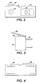
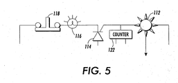
remote device 110. Figs. 2-4 show an exemplary embodiment of the outer structure of theremote device 110. Fig. 5 shows an exemplary embodiment of an electrical circuit within thedevice 110. Theremote device 110, in various exemplary embodiments, includes areceiver 112, acontrol switch 114, andindicator light 116 and areset switch 118. - The
receiver 112 receives a signal from thetransmitter 152. Acontrol switch 114 is electrically connected to thereceiver 112. Upon receiving a signal from thetransmitter 152, thereceiver 112 will apply a forward bias to thecontrol switch 114. Thecontrol switch 114 remains forward biased until the circuit is interrupted. Theindicator light 116 is electrically connected to thecontrol switch 114. Upon being placed into the forward bias condition, thecontrol switch 114 supplies electric current to theindicator light 116, to cause the indicator light 116 to emit light. - A cancel
switch 118 is electrically connected to theindicator light 116. The cancelswitch 118 is normally at a first position, indicated in Fig. 5, where the electrical connection of the circuit is maintained. The cancelswitch 118 is movable to a second position to interrupt the continuity of the circuit. Once the cancelswitch 118 has been moved to the second position, the electric current to theindicator light 116 has been interrupted. Thus, turning off theindicator light 116. In various exemplary embodiments, alever 120 is used to move the cancelswitch 118 from the first position to the second position. - After the cancel
switch 118 has been moved to the second location, atransmitter 128 associated with theremote device 110 sends a signal to areceiver 154 connected to thesupport system 150. Similarly, as discussed above for thetransmitter 152 andreceiver 112, thereceiver 154 connected to thesupport system 150 receives a signal from thetransmitter 128 connected to theremote device 110 with a similar signal. - In other exemplary embodiments, a portable transmitter can be used instead of the
transmitter 128 connected to theremote device 110. Thus, along with the cancel switch being move to the second position, the user can use the portable transmitter to send a signal which is received by thereceiver 154 connected to thesupport system 150. - In various exemplary embodiments, an
index counter 118 is located between thereceiver 112 andswitch 114. Theindex counter 122 indicates the number of parts required for that particularremote device 110. In various exemplary embodiments, theindex counter 122 is a numerical counter. However, it should be appreciated that any known or later-developed counter can be used to indicate to a user the number of parts required at a given location using theremote device 110. In further exemplary embodiments, instead of acounter 120,multiple devices 110 may be used for the same part. Thus, in this embodiment, the number of energizedindicator lights 116 will equal the total required number of that part. - In various exemplary embodiments, the
remote device 110 is supplied with electrical power via aplug 124, which is inserted into an electrical outlet. As shown in Fig. 1, in various exemplary embodiments, the electrical outlet is apower strip 126. In various exemplary embodiments, thepower strip 126 is a continuous slot outlet power strip placed along the shelf edge or other location. As should be appreciated, a voltage current is supplied from thestrip 126 to theplug 124. However, as should be appreciated, alternate power supply systems could be used to supply electrical power to theremote device 110. - The
remote device 110 can be imprinted with identification information to describe the part, including, but not limited the manufacturers part number, the user's identification number, a brief description of the part, or any other means for describing that part. Theremote device 110 can also be imprinted with information regarding the exact location of a storage location 132-144 such that a user can identify a building, zone, area, rack and/or any other location information used to locate a part. - When appropriate, a signal is sent from the
transmitter 152 to thereceiver 112 of a specificremote device 110 to indicate that a pick-up or a put-away operation is needed at that shelf location. When a signal is received, theindicator light 116 on thatremote device 110 will be turned on. Theindicator light 116 is turned off after the pick-up or put-away operation by the operator actuating the cancelswitch 118. Furthermore, if theremote device 110 contains theindex counter 122, theindex counter 122 will display the number of signals it has received and reset when the cancelswitch 118 is activated. - Fig. 6 is a flowchart outlining one exemplary embodiment of a teach/learn operation of the location indication system. The teach/learn sequence is used to associate an individual part with a storage location. Once the part has been associated with a storage location, the support system can thereafter transmit signals from the transmitter to the receiver placed at that storage location.
- Operation starts at step S100, and proceeds to S105, wherein the light indication system is placed in a teach/learn mode. In step S110, the support system goes to the first available database record in the memory of the support system in order to store information regarding an individual part with a storage location. In steps S115 and S120, the part label and the specific storage location label are thereafter scanned to associate the part with a specific shelf location. As such, the support system stores the identification information for a particular part for a particular storage location with the first available database record located in the memory of the support system.
- Then, in step S125, the remote device is plugged into a power strip that is associated with the scanned storage location. In step S130, after the remote device has been plugged into the power strip, a location code signal is sent from the transmitter associated with support system to activate the indicator light for that remote device. Also, in step S135, the newly powered remote device receives a transmitter code sequence. As such, when a remote device is plugged in, a portion of the transmitter code sequence becomes a string of zeros. The remote device recognizes that the sequence is incorrect and captures the next transmitter code sequence which is transmitted and retains that code until it is unplugged or reset. As should be appreciated, the remote device is plugged into a power strip as discussed above. Alternatively, the remote devices may be self powered with a reset button which selectively removes power from the remote device. As such, when the remote device is unplugged or reset, the transmitter code is automatically reset with a new transmitter code sequence. Thus, the remote device is not retained in an inappropriate transmitter code sequence when it is relocated because the transmitter code sequence is reset.
- Then, in step S140, the support system then goes to the next available database record in the memory of the support system in order to store information regarding another individual part with another storage location.
- In step S145, a determination is made as to whether another remote device is to be associated with another storage location for locating another part. If another remote device is to be added, operation returns to step S115. Otherwise, operation continues to step S150, where the teach/learn operation ends.
- As discussed, when a remote device is unplugged or removed from a specific remote location, the transmitter code sequence for that storage location is reset. As such, that specific remote device will reset and go through the teach/learn operation outlined in Fig. 6. As such, the remote devices are generic, low cost units that do not require tracking.
- After all the locations and parts have been recorded and the corresponding remote devices have been encoded, a pick-up or assembly operation sequence can be initiated. Depending on the request, the support system can either transmit a list of part location codes for a particular order or transmit a list for an assembly sequence.
- Fig. 7 is a flowchart outlining one exemplary embodiment of assembly operation of the location indication system. The assembly operation is used in model-mix and ship-to-order operations wherein an assembler may be handling the similar components sequentially. The assembly operation is also useful in reducing the operator training and ergonomic job rotation.
- The operation starts at step S200, and proceeds to step S205 wherein a unit is input either manually or automatically into the support system. The support system then compares the part lists to the storage database. Then, in step S210, the support system matches the assembly sequence. In matching the assembly sequence, the support system compares a part list to a storage database, and then filters and sorts the part list to match an assembly sequence.
- In step S215, the support system selects the first part as the current part. Then, in step S220, the support system sends a signal through the transmitter to the remote device in order to obtain the current part. By sending a signal to the remote device, the indicator light for that remote device is turned on.
- In step S225, the operator moves over to the remote device at the given storage location and picks up the current part. Thereafter, in step S230, the operator turns off the indicator light. By turning off the indicator light, in step S235, the remote device sends a signal through the transmitter to the receiver of the support system to indicate to the support system that the current part has been picked up. Then, in step S240, the support system sends a signal through the transmitter to turn on the indicator light for the next remote device, if necessary. If another part is not necessary, the support system does not send a signal to the remote device.
- In step S245, a determination is made by the user as to whether he believes no more parts need to be picked up, i.e., he believes the assembly sequences have been completed. If the user believes that all the parts have not been picked up, the operation proceeds to step S225 where the operator will pick up the next part. However, if the operator believes all the parts have been picked up, the operation proceeds to step S250.
- In step S250, the user attempts to scan out the complete unit using a handheld scanner associated with the support system. After all the parts have been scanned into the support system, a determination is made in step S260 by the support system as to whether all the parts have been picked up. An error may occur in failing to pick up all the parts when either the operator turns on the indicator light but fails to pick up the part, has lost the part during the assembly operation, or has simply failed to scan the part when scanning out. If the support system determines all the parts have been picked up, the support system accepts the scan out at S285 and the process thereafter ends at step S290. However, if all the parts have not been picked up, the operation proceeds to step S265 where the support system refuses to scan out the unit.
- In step S270, a determination is made as to whether an indicator light is on. If an indicator is on for at least one remote device, the support system maintains the indicator light on in step S275. Otherwise in step S280, the support system turns on the indicator light for the next part where the process thereafter returns to step S225.
- Fig. 7 is a flowchart outlining one exemplary embodiment of the pickup operation for line supply, kitting, indicating an order pickup for customer shipments. The flowchart of Fig. 8 is similar to Fig. 7, however, when using the pick up operation, a plurality of parts are picked up at a given zone, i.e., area, before moving on to another zone. Furthermore, in the pick up operation of Fig. 8, the order in which the parts are picked up are not material to the operation.
- The operation starts at step S300 and proceeds to step S305 where the system manually or automatically starts an operation. The support system thereafter compares the part list to the storage database S305. The support system will then compare the parts list to the storage database, filter and sort the parts to match the requested order.
- In step S315, an operator will enter into a rack area. Then, in step S320, the apparatus scans a zone label with a handheld transmitter. In step S325, a signal is sent from the handheld transmitter to the support system to indicate the current zone in which a user is present. It should be appreciated that the zone is any sizeable area in which a plurality of shelf locations and remote devices are located.
- In step S330, the support system turns on all the indicator lights for that zone. Then, in step S335, the operator will pick up a part. In step S340, the operator will turn off the indicator light for the remote device at that storage location. Thereafter, in step S345 the signal is sent by the remote device through a transmitter to the support system to indicate the part has been picked up.
- Then, in step S350, a determination is made as to whether the user believes all the indicator lights for that zone are off. If the user believes that an indicator light is on, the operation returns to step S335 where the operator picks up the next part. Otherwise, the operation proceeds to step S355.
- In step S355, a determination is made as to whether another zone is used. If the user believes that another zone is used, the operation proceeds to step S360 where the operator will go to the next zone. Otherwise, the operation proceeds to step S365 with the user will attempt to scan out the complete unit.
- In step S370, the support system determines if all of the parts have been picked up. If the support system determines that all of the parts have been picked up, the operation proceeds to step S385 where the support system accepts the scan out and the process thereafter ends at step S390. Otherwise, the operation proceeds to step S375.
- In step S375, the
support system 150 refuses the scan out. The support system refuses the scan out when either the operator fails to go to a zone, has failed to pick up a part, or has lost a part during a process of the pickup operation. Then, in step S380, the support system indicates the zone to the user of the missed part and the operation proceeds to step S320 where the operator will go the zone to pick up the part. - Fig. 9 is a flowchart outlining one exemplary embodiment of a put away operation. The put away operation is used to restock a remote device and to avoid having parts placed at the wrong storage location.
- The put-away operation begins in step S400 and proceeds to step S405. In step S405, the operator will scan the container label with a handheld transmitter. A signal is thereafter sent from the transmitter to the support system. In step S410, the support system then compares the parts list to the storage database. The support system then compares the parts list to the storage location list database, filters and sorts the database to match the most efficient sequence in order to store a part at a remote device. In step S415, the list thus created is the put away list.
- In step S420, the put away list then downloaded to the handheld scanner. In step S425, the operator will then enter into a zone. In step S430, the operator then scans the zone label. In step S435, the support system will then turn on the indicator light for the first or next part as the current part.
- In step S440, the operator will put away the part, and in step S445, will turn off the indicator light. In step S450, the remote device will then send a signal through a transmitter to the support system to indicate that the part has been put away.
- In step S455, the support system will then turn on the indicator light for the next part, if necessary. If another part is put away, the support system will not turn on another indicator light.
- In step S460, a determination is made by the user as to whether all the parts have been put away for that zone. If the user does not believe that all of the parts for that zone have been put away, the operation returns to step S440. Otherwise, the operation proceeds to step S465.
- In step S465, a determination is made by the user as to whether a part has to be placed in another zone. If the user believes another zone is used, the operator, in step S470, will proceed to the next zone. Otherwise, the operation proceeds to step S475.
- In step S475, the user will attempt to scan another container label for another put away operation. In step S480, a determination is made as to whether all the parts from the previous container have been put away. If the support system determines that all the parts have been put away, the operation returns to step S495 and the process ends. Otherwise, the operation proceeds to step S485.
- In step S485, the support system refuses to scan any container label because all of the parts from a previous put-away operation has not been completed. Then, in step S490, the support system indicates to the operator the remote devices in which a part was not placed. Thus, an operator can determine whether he has failed to put all the parts away or has misplaced a particular part.
Claims (10)
- A method of identifying a part with a storage location, comprising:transmitting identification information for the part and the storage location to a support system;supplying power to a remote device at the storage location;transmitting a code sequence, associated with the transmitted identification information, from the support system to the remote device, wherein the code sequence is a random code whose sequence is changed to a different code sequence when power is removed from the remote device; andnotifying an operator externally when attempting to locate the storage location.
- The method of claim 1, wherein the part is identified for an assembly operation, a part collection operation and/or a put-away operation.
- The method of claim 1 or claim 2, wherein the identification information for the part and the storage location is transmitted to a first available database record.
- The method of any of the preceding claims, wherein the random code is a rolling code sequence.
- A method according to any of the preceding claims, wherein the remote device is adapted to provide a visual and/or audible notification to the operator.
- A method according to any of the preceding claims, wherein a plurality of remote devices are provided at a corresponding plurality of storage locations, each remote device being responsive to a respective unique code sequence.
- A method according to any of the preceding claims, further comprising cancelling the notification to indicate that the part has been removed from the storage location.
- A method according to at least claim 6, further comprising transmitting code sequences to the remote devices in a predetermined sequence corresponding to the manufacturing sequence of a multi-part product.
- A method according to at least claim 6, further comprising causing the remote devices at a plurality of locations to issue notifications simultaneously.
- A part storage system comprising one or more storage locations and associated remote devices, and a support system for transmitting code sequences to the remote device(s), the or each remote device thereafter notifying an operator, the system being configured to carry out a method according to any of the preceding claims.
Applications Claiming Priority (2)
| Application Number | Priority Date | Filing Date | Title |
|---|---|---|---|
| US248763 | 1999-02-12 | ||
| US10/248,763 US6774783B1 (en) | 2003-02-14 | 2003-02-14 | Operation ready signal light device |
Publications (2)
| Publication Number | Publication Date |
|---|---|
| EP1447766A2 true EP1447766A2 (en) | 2004-08-18 |
| EP1447766A3 EP1447766A3 (en) | 2005-05-04 |
Family
ID=32680600
Family Applications (1)
| Application Number | Title | Priority Date | Filing Date |
|---|---|---|---|
| EP04250773A Withdrawn EP1447766A3 (en) | 2003-02-14 | 2004-02-12 | Operation ready signal light device |
Country Status (3)
| Country | Link |
|---|---|
| US (1) | US6774783B1 (en) |
| EP (1) | EP1447766A3 (en) |
| JP (1) | JP2004244219A (en) |
Cited By (1)
| Publication number | Priority date | Publication date | Assignee | Title |
|---|---|---|---|---|
| EP1889222A2 (en) * | 2005-05-31 | 2008-02-20 | Symbol Technologies, Inc. | Methods and apparatus for locating devices |
Families Citing this family (2)
| Publication number | Priority date | Publication date | Assignee | Title |
|---|---|---|---|---|
| AU2002256110A1 (en) * | 2001-04-09 | 2002-10-28 | John Stevens | Tote-based warehousing system and method |
| US8965794B2 (en) * | 2003-03-07 | 2015-02-24 | Hy-Ko Products | Retail identification and inventory system |
Citations (4)
| Publication number | Priority date | Publication date | Assignee | Title |
|---|---|---|---|---|
| US4510495A (en) * | 1982-08-09 | 1985-04-09 | Cornell Research Foundation, Inc. | Remote passive identification system |
| US4701849A (en) * | 1986-03-07 | 1987-10-20 | Elden Michael G | System for summoning service personnel and monitoring their response time |
| US5113349A (en) * | 1988-03-26 | 1992-05-12 | Fuji Electric Co. Ltd. | Method and system for storing/removing and distributing articles of manufacture |
| US20020109597A1 (en) * | 1995-03-29 | 2002-08-15 | Medical Tracking Systems, Inc. | Wide area multipurpose tracking system |
Family Cites Families (12)
| Publication number | Priority date | Publication date | Assignee | Title |
|---|---|---|---|---|
| US4519522A (en) * | 1981-07-06 | 1985-05-28 | Photo Vending Corporation | Apparatus and method for storing and retrieving articles |
| US4642017A (en) * | 1982-09-30 | 1987-02-10 | Amca International Corporation | Automated in-process pipe storage and retrieval system |
| JPS6183606U (en) * | 1984-11-07 | 1986-06-02 | ||
| US4796209A (en) * | 1986-06-26 | 1989-01-03 | Allegheny Ludlum Corporation | Random inventory system |
| JPH0784245B2 (en) * | 1988-07-12 | 1995-09-13 | 富士電機株式会社 | Logistics equipment |
| JPH0720762B2 (en) * | 1988-03-26 | 1995-03-08 | 富士電機株式会社 | Logistics equipment |
| JPH078684B2 (en) * | 1990-02-22 | 1995-02-01 | 株式会社クボタ | Electronic shelf label device |
| JP3178479B2 (en) * | 1992-03-06 | 2001-06-18 | ソニー株式会社 | Remote control transmitter and remote control system |
| US5812986A (en) * | 1996-02-23 | 1998-09-22 | Danelski; Darin L. | RF light directed inventory system |
| US6650225B2 (en) * | 2000-12-11 | 2003-11-18 | Asap Automation, Llc | Wireless directed inventory system |
| US6694217B2 (en) * | 2001-05-24 | 2004-02-17 | Breakthrough Logistics Corporation | Automated system for efficient article storage and self-service retrieval |
| JP2003040406A (en) * | 2001-07-26 | 2003-02-13 | Yokogawa Electric Corp | Picking system |
-
2003
- 2003-02-14 US US10/248,763 patent/US6774783B1/en not_active Expired - Fee Related
-
2004
- 2004-02-09 JP JP2004031655A patent/JP2004244219A/en active Pending
- 2004-02-12 EP EP04250773A patent/EP1447766A3/en not_active Withdrawn
Patent Citations (4)
| Publication number | Priority date | Publication date | Assignee | Title |
|---|---|---|---|---|
| US4510495A (en) * | 1982-08-09 | 1985-04-09 | Cornell Research Foundation, Inc. | Remote passive identification system |
| US4701849A (en) * | 1986-03-07 | 1987-10-20 | Elden Michael G | System for summoning service personnel and monitoring their response time |
| US5113349A (en) * | 1988-03-26 | 1992-05-12 | Fuji Electric Co. Ltd. | Method and system for storing/removing and distributing articles of manufacture |
| US20020109597A1 (en) * | 1995-03-29 | 2002-08-15 | Medical Tracking Systems, Inc. | Wide area multipurpose tracking system |
Cited By (2)
| Publication number | Priority date | Publication date | Assignee | Title |
|---|---|---|---|---|
| EP1889222A2 (en) * | 2005-05-31 | 2008-02-20 | Symbol Technologies, Inc. | Methods and apparatus for locating devices |
| EP1889222A4 (en) * | 2005-05-31 | 2010-06-23 | Symbol Technologies Inc | Methods and apparatus for locating devices |
Also Published As
| Publication number | Publication date |
|---|---|
| JP2004244219A (en) | 2004-09-02 |
| EP1447766A3 (en) | 2005-05-04 |
| US6774783B1 (en) | 2004-08-10 |
Similar Documents
| Publication | Publication Date | Title |
|---|---|---|
| US4814742A (en) | Inquiry system for detecting a selected object | |
| CA2591289C (en) | Methods and systems for locating and identifying labware using radio-frequency indentification tags | |
| US7221276B2 (en) | Systems and methods for using radio frequency identification tags to communicating sorting information | |
| CN1637757A (en) | Product identification data management system and product identification data management method | |
| WO2007131839A1 (en) | METHOD AND SYSTEMS FOR LOCALIZING OBJECTS USING PASSIVE RFID TAGs | |
| JP4853386B2 (en) | Article storage support system | |
| JP2006054118A (en) | Wiring support system | |
| EP1447766A2 (en) | Operation ready signal light device | |
| JP2008040640A (en) | Work management apparatus, work management system, work management method, and picking carriage | |
| EP0990171B1 (en) | Method and device for determining the location of objects | |
| CN108960698A (en) | The method and apparatus for indicating the storage location of material | |
| CN112389936B (en) | Intelligent goods shelf and material storage method | |
| CN113034067A (en) | Warehouse management method, computer device and readable storage medium | |
| US20110080281A1 (en) | System for Managing Mail Carriers in a Sorting Facility Using Persistent Asset Routing Terminals | |
| JPH0281899A (en) | Fork lift | |
| CN111966112A (en) | Automatic file storage, method and device for loading and unloading files and electronic equipment | |
| JPH0281900A (en) | Communication device for fork lift | |
| JP3828294B2 (en) | Information communication system in product sorting equipment and number display device in product sorting equipment | |
| CN114137866B (en) | Intelligent goods shelf fool-proof detection system and management method | |
| CN113034068B (en) | Warehouse management system and warehouse management method | |
| JP2007076885A (en) | Position guide system | |
| CN115069600A (en) | Material sorting method, device, equipment and storage medium | |
| JPH11343012A (en) | Method of and device for picking merchandise | |
| JP2008094514A (en) | Shipping instructing device | |
| CN114291475A (en) | Material access equipment and control method and device thereof |
Legal Events
| Date | Code | Title | Description |
|---|---|---|---|
| PUAI | Public reference made under article 153(3) epc to a published international application that has entered the european phase |
Free format text: ORIGINAL CODE: 0009012 |
|
| AK | Designated contracting states |
Kind code of ref document: A2 Designated state(s): AT BE BG CH CY CZ DE DK EE ES FI FR GB GR HU IE IT LI LU MC NL PT RO SE SI SK TR |
|
| AX | Request for extension of the european patent |
Extension state: AL LT LV MK |
|
| PUAL | Search report despatched |
Free format text: ORIGINAL CODE: 0009013 |
|
| AK | Designated contracting states |
Kind code of ref document: A3 Designated state(s): AT BE BG CH CY CZ DE DK EE ES FI FR GB GR HU IE IT LI LU MC NL PT RO SE SI SK TR |
|
| AX | Request for extension of the european patent |
Extension state: AL LT LV MK |
|
| 17P | Request for examination filed |
Effective date: 20051104 |
|
| AKX | Designation fees paid |
Designated state(s): DE FR GB |
|
| STAA | Information on the status of an ep patent application or granted ep patent |
Free format text: STATUS: THE APPLICATION IS DEEMED TO BE WITHDRAWN |
|
| 18D | Application deemed to be withdrawn |
Effective date: 20160421 |