EP1442848B1 - Robot hand for taking out objects with means for changing the orientation of the hand - Google Patents
Robot hand for taking out objects with means for changing the orientation of the hand Download PDFInfo
- Publication number
- EP1442848B1 EP1442848B1 EP04250500A EP04250500A EP1442848B1 EP 1442848 B1 EP1442848 B1 EP 1442848B1 EP 04250500 A EP04250500 A EP 04250500A EP 04250500 A EP04250500 A EP 04250500A EP 1442848 B1 EP1442848 B1 EP 1442848B1
- Authority
- EP
- European Patent Office
- Prior art keywords
- holding
- orientation
- robot arm
- hand
- holding means
- Prior art date
- Legal status (The legal status is an assumption and is not a legal conclusion. Google has not performed a legal analysis and makes no representation as to the accuracy of the status listed.)
- Expired - Fee Related
Links
Images


Classifications
-
- B—PERFORMING OPERATIONS; TRANSPORTING
- B25—HAND TOOLS; PORTABLE POWER-DRIVEN TOOLS; MANIPULATORS
- B25J—MANIPULATORS; CHAMBERS PROVIDED WITH MANIPULATION DEVICES
- B25J9/00—Programme-controlled manipulators
- B25J9/16—Programme controls
- B25J9/1694—Programme controls characterised by use of sensors other than normal servo-feedback from position, speed or acceleration sensors, perception control, multi-sensor controlled systems, sensor fusion
- B25J9/1697—Vision controlled systems
-
- B—PERFORMING OPERATIONS; TRANSPORTING
- B25—HAND TOOLS; PORTABLE POWER-DRIVEN TOOLS; MANIPULATORS
- B25J—MANIPULATORS; CHAMBERS PROVIDED WITH MANIPULATION DEVICES
- B25J15/00—Gripping heads and other end effectors
-
- G—PHYSICS
- G05—CONTROLLING; REGULATING
- G05B—CONTROL OR REGULATING SYSTEMS IN GENERAL; FUNCTIONAL ELEMENTS OF SUCH SYSTEMS; MONITORING OR TESTING ARRANGEMENTS FOR SUCH SYSTEMS OR ELEMENTS
- G05B2219/00—Program-control systems
- G05B2219/30—Nc systems
- G05B2219/40—Robotics, robotics mapping to robotics vision
- G05B2219/40053—Pick 3-D object from pile of objects
Definitions
- the present invention relates to an object taking-out apparatus for taking out an object using a robot hand, and more particularly, to an object taking-out apparatus provided with object holding means whose orientation is changeable according to a condition of placement of an object.
- robots have been made more intelligent to perform operations on objects. For example, an operation of taking out objects which are randomly stacked in a container or on a pallet is a typical application of a robot having a hand attached to an arm end.
- the position/orientation of each individual object is detected by means of a visual sensor or the like, and according to the detected result, the operating position/orientation of the robot is determined before taking out the objects.
- both the robot arm and the robot hand should not interfere with the container. This usually imposes limitations on the taking out of the objects. Specifically, objects that can be taken out without causing interaction such as interference are limited to those adequately spaced away from the peripheral wall of the container and not tilting toward the container wall. These requirements make it difficult to remove all the objects from the container.
- JP 2002-331480A operates to actively change the orientation of the robot arm and the rotary position of the robot wrist, so that they do not enter a preset interaction region, thereby avoiding interaction between the container and the robot arm or hand.
- this kind of prior art still cannot remove objects placed near or tilting toward the container wall and objects surrounded by other objects highly stacked around them.
- JP-A-07 116 984 an object taking-out apparatus according to the precharacterising part of attached claim 1, wherein the orientation of a robot hand can be changed to selectively take one of a plurality of orientations prior to the holding of an object to be taken out from a container containing other such objects.
- the present invention provides an object taking-out apparatus capable of substantially eliminating the problem of interaction between parts of the robot and the container, thereby greatly to reduce restriction on a placement condition of an object to be taken out from such container.
- an object taking-out apparatus for taking out an object, comprising a robot having a robot arm; a hand attached to a distal end of the robot arm and having holding means for holding an object; a visual sensor for detecting a condition of placement of an object to be taken out; and a controller for issuing commands to said hand, wherein:
- the orientation of the holding means attached to the distal end of the robot arm may be changed according to the position/orientation of an object to be taken out, presence of overlapping with another object, positional relation with the container wall, or the like, so as to alleviate object taking-out requirements, thus avoiding a condition in which an object is unable to be taken out.
- the first orientation is set such that a direction of a holding axis of the holding means is closest to a direction of a rotational axis of the distal end of the robot arm in the plurality of orientations to form a predetermined angle not equal to zero degree, e.g. equal to or less than 45 degrees, between the direction of the holding axis and the direction of the rotational axis of the distal end of the robot arm.
- the holding means has a center of holding offset from a center axis of a proximal portion thereof.
- the center of holding is not offset, the hand must be moved so that the center axis of the proximal portion coincides with the center axis of the object to be taken out. This results in a fear that the hand may interfere with the container wall, if a condition of the distance between the object center and the container wall being larger than the interaction radius of the hand, is not satisfied.
- the holding means of the hand may be caused to assume a position where a predetermined angle is formed between a holding axis of the holding means and a rotational axis of the distal end of the robot arm, whereby the necessity of bringing the hand close to the container wall is eliminated to avoid interaction therebetween.
- the predetermined angle may be an angle close to zero degree, if the object inclination is small.
- the second orientation be set to form an angle substantially equal to 90 degrees between the holding axis and the rotational axis of the robot arm end. Even if most part of a space in the vicinity of the object to be taken out is occupied by other objects, the holding means assuming the second orientation can have access to the object to be taken out through an unoccupied part of the vicinity space and hold that object without causing interaction with other objects.
- the object taking-out apparatus may be provided with a visual sensor having means for storing taught image models of an object as seen from different directions, and means for comparing a captured image of the object with the taught image models and for selecting one of the taught image models according to a degree of conformity.
- the orientation changing means can change the orientation of the holding means according to the selected taught image model before the object is held.
- a condition of how objects overlap one another may be detected by use of the visual sensor, and a held position of the object by the holding means may be changed according to the detected condition.
- the use of the visual sensor is effective especially when the object to be taken out partly overlaps another object. Specifically, the object partly overlapping another object can be held without causing interaction, by holding that part of the object which is specified in advance by the visual sensor as being able to be held.
- the visual sensor has image capturing means attached to the robot arm end through a slider mechanism that is movable in directions away from and toward the robot arm end.
- the image capturing means is moved in the direction away from the robot arm end at a time of image capturing, and moved in the direction toward the robot arm end at a time of the object being held, whereby the fear of causing interaction can be reduced.
- the visual sensor must be brought close to that object in order to take an accurate image thereof, and thus the fear of causing interaction between the hand and the highly stacked objects increases.
- the image capturing means attached to the slider mechanism can be moved in the direction away from the robot arm end at the time of image capturing, thereby preventing the interaction.
- the image capturing means can be retreated in the opposite direction, thereby preventing the image capturing from hindering the holding of the object.
- this invention makes it possible to remove objects irrespective of what conditions they are placed in, while preventing interaction between the hand and the container wall and between the visual sensor and objects other than the object to be taken out.
- the orientation of the holding means can be changed according to the position/orientation of the object to be taken out, the positional relation between the object and the container wall, the inclination of the object, the overlapping between the object and other objects, etc., whereby the object taking-out apparatus can flexibly deal with various conditions in which objects are placed.
- the efficiency and cost effectiveness of object taking-out can be improved.
- the problem of object taking-out being limited due to interaction between the hand and the container and between the visual sensor and objects can be eliminated, and as a result, damages to the hand, visual sensor, objects, etc. can also be prevented.
- reference numeral 1 denotes a vertical articulated robot (hereinafter simply referred to as robot) connected via cables 6 to a robot controller 2 for controlling the operation of the robot 1.
- the robot 1 has an arm having a distal end thereof mounted with a hand 3 and a three dimensional visual sensor.
- This visual sensor has a sensor head which includes image capturing means and which will be referred to as image capturing means 4.
- the hand 3 is provided with holding mechanism (serving as object holding means), mentioned later, which is controlled by the robot controller 2. Control signals and electric power are supplied to the hand 3 through cables 8 extending between the robot hand and the robot controller 2.
- the three dimensional visual sensor may be for example a conventional one that is a combination of a light projector for irradiating patterned light such as slit light or spot light and a CCD video camera (serving as image capturing means) for detecting reflected light.
- the CCD video camera may also be used for ordinary picture taking to obtain a two-dimensional image without light projection.
- the image capturing means (sensor head) 4 of the three dimensional visual sensor is connected through cables 9 to a control processor 5 for the visual sensor.
- the control processor 5 which may be for example a personal computer, comprises hardware and software for controlling sensing operations (light projection, image capturing, etc.) of the visual sensor, and for processing photodetection signals (video image signals) obtained by the sensing (including ordinary picture-taking), and for transmitting, as mentioned later, the desired information to the robot controller 2 through a LAN network 7.
- a large number of objects 13 to be taken out by the robot hand 3 are received and randomly stacked in a basket-like container 11 placed near the robot 1.
- the container 11 may be one having a peripheral wall 12 that defines an upper opening which is rectangular in cross section, however in general, the container shape is not limited thereto.
- the hand 3 is attached through a coupling member 31 to a mount 41 that is mounted to the distal end 10 of the robot arm.
- a telescopic mechanism is provided that has telescopic means 32 adapted to be driven for example by a pneumatic cylinder or the like.
- Holding means (hand body) 35 for griping an object is pivotally supported by rotary supports (pivotal axes) 33, 34 that are individually provided near distal ends of the coupling member 31 and the telescopic means 32.
- the holding means 35 may be in forms of such as a chuck having closing pawls for holding an object, a vacuum or magnetic suction pad for sucking an object.
- the type of holding means for use is selected in accordance with the shape, material, weight, etc. of the object to be held.
- holding means of a type having closing members 35a, 35 is used by way of example.
- electric power and commands for holding operations are supplied from the robot controller 2 to the holding means.
- the telescopic means 32 With expansion and contraction of telescopic means 32, the holding means 35 rotates around the rotary support 33 where it is coupled to the coupling member 31, to thereby change its orientation.
- the telescopic means 32 has a plurality of expansion-contraction positions which are set beforehand and between which a changeover is made in accordance with a command from the robot controller 2.
- the expansion-contraction positions include one where the holding means 35 assumes a first orientation shown in FIG. 2a and another one where it assumes a second orientation shown in FIG. 2b .
- a predetermined angle ⁇ 1 is formed between a holding axis A of the holding means 35 and a rotational axis B of the distal end 10 of the robot arm.
- the angle formed between these two axes A, B will be referred to as holding angle
- holding angles corresponding to the first and the second orientations will be referred to as first and second holding angles, respectively.
- the first holding angle is set to be larger than zero degree (for example, equal to or larger than 10 degrees) and less than or equal to 45 degrees. This setting is intended for convenience of taking-out of an object disposed in the container 11 to tilt toward the container wall 12, as will be described with reference also to FIG. 3 .
- the first holding angle when the first holding angle is set to be larger than zero degree, an object 13a tilting toward the container wall 12 can be held and taken out from the container without causing interaction.
- the first holding angle is zero, the normal line to the top surface of the object 13a coincides with the axis of the robot arm end, and if the object 13a to be taken out is disposed near the container wall 12 so that the normal line to the object 13a crosses the container wall 12, especially a lower part of the wall, there is a great fear that the robot hand 3 or the robot arm moving along its axis or the normal line to the obj ect 13a interferes with the container wall 12 except for a case where the tilting angle of the object 13a is small.
- the holding angle (an angle ⁇ 2 formed between the holding direction axis of the holding means 35 and the axis of the robot arm end 10) is about 90 degrees.
- the holding means 35 of the robot hand 3 can access an object, which is to be taken out, from a direction in which no object is present in a space near the object to be taken out, and can hold the object without causing interaction with other objects.
- the holding means 35 of the hand 3 is configured such that its holding center C is located offset from the center axis D of a proximal portion of the hand 3. This eliminates the necessity of causing the center axis of the proximal portion of the hand to coincide with that of the object at the time of object taking-out, making it possible to allow the hand to assume such a position where the proximal portion of the hand is located offset inwardly of the container, as shown in FIG. 4 in which reference numeral 13b denotes an object to be taken out using the holding means 35 and located close to the peripheral wall 12 of the container.
- the image capturing means (which may include a light projector) 4 is fixedly mounted to the mount 41 at the robot arm end 10.
- the positional relation between the holding means 35 and the image capturing means 4 is kept unchanged, except for changes in orientation of the holding means 35.
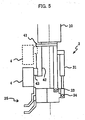
- FIG. 5 shows an example of the hand construction having such a slide mechanism, in which the image capturing means 4 of the visual sensor is not fixedly mounted to the mount 41 at the robot arm end 10, but mounted thereto through a slider mechanism 42 for moving the image capturing means 4 in a direction parallel to the axis of the robot arm end 10.
- Reference numeral 43 denotes a carrier for the image capturing means 4.
- the carrier 43 is arranged to be movable on the slider mechanism 42, thus making the image capturing means 4 movable.
- the slider mechanism 42 is connected to the robot controller 2, so that the position of the carrier 43, and by extension the position (slide position) of the image capturing means 4, is controlled in accordance with a command supplied from the robot controller 2.
- This method for interaction avoidance is effective especially when, as shown in FIG. 6 , the object 13c to be subject to the image capturing or the holding is located deeply below the surrounding objects.
- the position, shown by the solid line, of the image capturing means 4 indicates an example of the slide position for capturing the image of the object 13c
- the position shown by the dotted line of the image capturing means 4 indicates an example of the slide position for holding the object 13c.
- objects 13 in the container 11 are taken out one by one.
- the following is a typical outline of procedures, after which the objects 13 are taken out by the holding means 35 of the hand 3.
- Step S1 a determination is made as to whether or not the object attempted to be taken out is in an upright orientation.
- images of an object is taken from different directions using the image capturing means 4, and based on these images, taught image models are prepared beforehand in the control processor 5.
- the image of the object taken in the second image capturing position is compared with the taught image models, and the taught image model with the highest conformity is selected to determine whether the object is in an upright orientation or not.
- Step S2 If the result of determination at Step S1 is negative (No), whether or not the object attempted to be taken out overlaps another object is determined (Step S2). In this determination, as for objects of annular ring shape, the determination result is affirmative (Yes), if the oval arc profile of the object attempted to be taken out is disconnected by another oval arc profile. If not so, the determination result is negative.
- Step S3 inside-holding is selected (Step S3), in which the object 21 is held from inside by opening the closing members 35a, 35b (see, FIGS. 2a and 2b ) of the holding means 35. Specifically, in the inside-holding, the holding means 35 is moved close to the object 21 from above, and then the closing members 35a, 35b are opened to be brought in urged contact with the inner peripheral surface of the object 21, whereby the object 21 is held.
- Step S4 outside-holding is selected (Step S4), in which an arcuate portion of the object 22, not covered by another object 23, is held from both sides by closing the closing members 35a, 35b. Specifically, when the object 22 overlaps another object 23, the holding means 35 is moved close to the object 22 from above, and then the closing members 35a, 35b are closed to be brought in urged contact with the inner and outer peripheral surfaces of the object 22, respectively, whereby the object 22 is held.
- Step S5 whether or not an empty area is present on both sides of the object attempted to be taken out.
- an empty area is present on both sides (object 24)
- a narrow band-shaped profile representing another upright object
- object 25 it is determined that an empty area is present on one side (object 25).
- other upright objects 27, 29 are detected on both sides, it is determined that no empty area is present (object 28).
- top-holding, side-holding, and unable to hold are selected, respectively (Steps S6, S7 and S8).
- the top-holding and the side-holding belong to a so-called vertical holding.
- the holding means 35 In the top-holding, the holding means 35 is moved close to the object 24 from above, and then the closing members 35a, 35b are closed to be brought in urged contact with both end surfaces of the object 24, respectively, whereby the object 24 is held.
- the holding means 35 In the side-holding for a case where an empty space is present only on one side of the object 25, the holding means 35 is moved close to the object 25 from lateral side, utilizing the empty space, and then the closing members 35a, 35b are closed to be brought in urged contact with the inner and outer peripheral surfaces of the object 25, respectively, thus holding the object 25.
- Step S8 If the unable to hold condition is determined at Step S8, the object to be taken out at this time is changed to the second best object that can be determined according to the rules in procedure (4). Whereupon, the procedure (5) and subsequent procedures are repeated.
- Step S3 S4, S6, or S7 is reached. If Step S8 is reached for all the objects detected in procedure (3), an alarm is output and the system is caused to stop, though this situation hardly occurs.
- Step S8 is reached for all the objects detected in procedure (3), an alarm is output and the system is caused to stop, though this situation hardly occurs.
- other objects are taken out ahead of the same. In general, therefore, there is a high possibility that a space is produced at least one side of the object that was determined as being unable to hold.
- telescopic means for changing the orientation of the holding means of the hand it may be a telescopic mechanism having an electric motor serving as a drive source, instead of a hydraulic cylinder used in the embodiment.
- a mechanism having a rotary mechanism provided at one end of a coupling member and driven by an electric motor, for directly rotating the holding means to change the orientation of the same.
Description
- The present invention relates to an object taking-out apparatus for taking out an object using a robot hand, and more particularly, to an object taking-out apparatus provided with object holding means whose orientation is changeable according to a condition of placement of an object.
- Recently, robots have been made more intelligent to perform operations on objects. For example, an operation of taking out objects which are randomly stacked in a container or on a pallet is a typical application of a robot having a hand attached to an arm end. For taking out the objects which are randomly stacked and which are not subjected to positioning, the position/orientation of each individual object is detected by means of a visual sensor or the like, and according to the detected result, the operating position/orientation of the robot is determined before taking out the objects.
- In taking out objects which are randomly stacked in a container, both the robot arm and the robot hand should not interfere with the container. This usually imposes limitations on the taking out of the objects. Specifically, objects that can be taken out without causing interaction such as interference are limited to those adequately spaced away from the peripheral wall of the container and not tilting toward the container wall. These requirements make it difficult to remove all the objects from the container.
- To avoid the interaction problem, an interaction avoiding apparatus is proposed for example in
JP 2002-331480A - There is further disclosed in
JP-A-07 116 984 claim 1, wherein the orientation of a robot hand can be changed to selectively take one of a plurality of orientations prior to the holding of an object to be taken out from a container containing other such objects. - The present invention provides an object taking-out apparatus capable of substantially eliminating the problem of interaction between parts of the robot and the container, thereby greatly to reduce restriction on a placement condition of an object to be taken out from such container.
- According to the present invention there is provided an object taking-out apparatus for taking out an object, comprising a robot having a robot arm; a hand attached to a distal end of the robot arm and having holding means for holding an object; a visual sensor for detecting a condition of placement of an object to be taken out; and a controller for issuing commands to said hand, wherein:
- said hand has orientation changing means operable for changing orientation of said holding means to selectively take one of a plurality of orientations including a first orientation and a second orientation different from each other with respect to said robot arm in accordance with a command from said controller which is operable to issue the command to said hand prior to holding of the object in accordance with the condition of placement of the object to be taken out as detected by said visual sensor, thereby to change selectively the orientation of said holding means prior to the holding of the object;
- In operation, the orientation of the holding means attached to the distal end of the robot arm may be changed according to the position/orientation of an object to be taken out, presence of overlapping with another object, positional relation with the container wall, or the like, so as to alleviate object taking-out requirements, thus avoiding a condition in which an object is unable to be taken out.
- It is preferable that the first orientation is set such that a direction of a holding axis of the holding means is closest to a direction of a rotational axis of the distal end of the robot arm in the plurality of orientations to form a predetermined angle not equal to zero degree, e.g. equal to or less than 45 degrees, between the direction of the holding axis and the direction of the rotational axis of the distal end of the robot arm.
- Preferably, the holding means has a center of holding offset from a center axis of a proximal portion thereof. With this arrangement, objects even placed near the container wall can be held, without moving the hand to bring the center of the proximal portion of the hand close to the container wall. If the center of holding is not offset, the hand must be moved so that the center axis of the proximal portion coincides with the center axis of the object to be taken out. This results in a fear that the hand may interfere with the container wall, if a condition of the distance between the object center and the container wall being larger than the interaction radius of the hand, is not satisfied.
- In taking out an object tilting toward the container wall, the holding means of the hand may be caused to assume a position where a predetermined angle is formed between a holding axis of the holding means and a rotational axis of the distal end of the robot arm, whereby the necessity of bringing the hand close to the container wall is eliminated to avoid interaction therebetween. The predetermined angle may be an angle close to zero degree, if the object inclination is small.
- Next, as for the second orientation that can be assumed by the holding means, it is preferable that the second orientation be set to form an angle substantially equal to 90 degrees between the holding axis and the rotational axis of the robot arm end. Even if most part of a space in the vicinity of the object to be taken out is occupied by other objects, the holding means assuming the second orientation can have access to the object to be taken out through an unoccupied part of the vicinity space and hold that object without causing interaction with other objects.
- The object taking-out apparatus may be provided with a visual sensor having means for storing taught image models of an object as seen from different directions, and means for comparing a captured image of the object with the taught image models and for selecting one of the taught image models according to a degree of conformity. With use of this kind of visual sensor, the orientation changing means can change the orientation of the holding means according to the selected taught image model before the object is held.
- A condition of how objects overlap one another may be detected by use of the visual sensor, and a held position of the object by the holding means may be changed according to the detected condition.
- The use of the visual sensor is effective especially when the object to be taken out partly overlaps another object. Specifically, the object partly overlapping another object can be held without causing interaction, by holding that part of the object which is specified in advance by the visual sensor as being able to be held.
- The visual sensor has image capturing means attached to the robot arm end through a slider mechanism that is movable in directions away from and toward the robot arm end. The image capturing means is moved in the direction away from the robot arm end at a time of image capturing, and moved in the direction toward the robot arm end at a time of the object being held, whereby the fear of causing interaction can be reduced.
- Specifically, if the object to be taken out is surrounded by highly stacked other objects, the visual sensor must be brought close to that object in order to take an accurate image thereof, and thus the fear of causing interaction between the hand and the highly stacked objects increases. In this invention, only the image capturing means attached to the slider mechanism can be moved in the direction away from the robot arm end at the time of image capturing, thereby preventing the interaction. At the time of holding the object, the image capturing means can be retreated in the opposite direction, thereby preventing the image capturing from hindering the holding of the object.
- As described above, this invention makes it possible to remove objects irrespective of what conditions they are placed in, while preventing interaction between the hand and the container wall and between the visual sensor and objects other than the object to be taken out. Specifically, the orientation of the holding means can be changed according to the position/orientation of the object to be taken out, the positional relation between the object and the container wall, the inclination of the object, the overlapping between the object and other objects, etc., whereby the object taking-out apparatus can flexibly deal with various conditions in which objects are placed. Thus, the efficiency and cost effectiveness of object taking-out can be improved. The problem of object taking-out being limited due to interaction between the hand and the container and between the visual sensor and objects can be eliminated, and as a result, damages to the hand, visual sensor, objects, etc. can also be prevented.
- Since there is thus no fear that the position/orientation of the image capturing means may be dislocated due to such interaction, an object taking out operation can be made without interruption for recalibration of the image capturing means to correct the dislocation.
-
-
FIG. 1 is a view showing the overall arrangement of an object taking-out apparatus according to the preamble ofclaim 1 only; -
FIG. 2a is a schematic view showing the construction of a hand used in the apparatus ofFig. 1 , in a state where a holding mechanism of the hand is in a first orientation, andFIG. 2b is a view showing the holding mechanism which is in a second orientation; -
FIG. 3 is a view showing an orientation of the hand used in the apparatus ofFig. 1 for holding an object tilting toward a container wall; -
FIG. 4 is a view showing an orientation of the hand used in the apparatus ofFig. 1 for holding an object located near the container wall; -
FIG. 5 is a schematic view of a hand having a visual sensor whose image capturing means is arranged to be movable, in accordance with the present invention. -
FIG. 6 is a view for explaining how the image of an object surrounded by highly stacked objects is taken and how the object is gripped by means of the hand shown inFIG. 5 , without causing interaction between the hand and the stacked objects; and -
FIG. 7 is a view showing by way of example a flowchart of procedures for selecting a way of object holding according to results of image capturing and three-dimensional visual measurement, together with a relation between conditions of objects and ways of holding. - With reference to the appended drawings, an object taking-out apparatus according to the present invention will be explained, whereby the essential aspect of movable image capturing means is discussed only with reference to
Fig. 5 andFig. 6 . - In
FIG. 1 ,reference numeral 1 denotes a vertical articulated robot (hereinafter simply referred to as robot) connected viacables 6 to arobot controller 2 for controlling the operation of therobot 1. Therobot 1 has an arm having a distal end thereof mounted with ahand 3 and a three dimensional visual sensor. This visual sensor has a sensor head which includes image capturing means and which will be referred to as image capturing means 4. Thehand 3 is provided with holding mechanism (serving as object holding means), mentioned later, which is controlled by therobot controller 2. Control signals and electric power are supplied to thehand 3 throughcables 8 extending between the robot hand and therobot controller 2. - The three dimensional visual sensor may be for example a conventional one that is a combination of a light projector for irradiating patterned light such as slit light or spot light and a CCD video camera (serving as image capturing means) for detecting reflected light. The CCD video camera may also be used for ordinary picture taking to obtain a two-dimensional image without light projection.
- The image capturing means (sensor head) 4 of the three dimensional visual sensor is connected through cables 9 to a
control processor 5 for the visual sensor. Thecontrol processor 5, which may be for example a personal computer, comprises hardware and software for controlling sensing operations (light projection, image capturing, etc.) of the visual sensor, and for processing photodetection signals (video image signals) obtained by the sensing (including ordinary picture-taking), and for transmitting, as mentioned later, the desired information to therobot controller 2 through aLAN network 7. - In this embodiment, a large number of
objects 13 to be taken out by therobot hand 3 are received and randomly stacked in a basket-like container 11 placed near therobot 1. Thecontainer 11 may be one having aperipheral wall 12 that defines an upper opening which is rectangular in cross section, however in general, the container shape is not limited thereto. - The construction and functions of the
hand 3 will be described with reference toFIGS. 2a and 2b . - As shown in
FIGS. 2a and 2b , thehand 3 is attached through acoupling member 31 to amount 41 that is mounted to thedistal end 10 of the robot arm. In parallel to thecoupling member 31, a telescopic mechanism is provided that has telescopic means 32 adapted to be driven for example by a pneumatic cylinder or the like. Holding means (hand body) 35 for griping an object is pivotally supported by rotary supports (pivotal axes) 33, 34 that are individually provided near distal ends of thecoupling member 31 and the telescopic means 32. - The holding means 35 may be in forms of such as a chuck having closing pawls for holding an object, a vacuum or magnetic suction pad for sucking an object. The type of holding means for use is selected in accordance with the shape, material, weight, etc. of the object to be held. In this embodiment, holding means of a type having
closing members robot controller 2 to the holding means. - With expansion and contraction of telescopic means 32, the holding means 35 rotates around the
rotary support 33 where it is coupled to thecoupling member 31, to thereby change its orientation. The telescopic means 32 has a plurality of expansion-contraction positions which are set beforehand and between which a changeover is made in accordance with a command from therobot controller 2. The expansion-contraction positions include one where the holding means 35 assumes a first orientation shown inFIG. 2a and another one where it assumes a second orientation shown inFIG. 2b . - In the first orientation, a predetermined angle θ1, not equal to zero, is formed between a holding axis A of the holding means 35 and a rotational axis B of the
distal end 10 of the robot arm. Hereinafter, the angle formed between these two axes A, B will be referred to as holding angle, and holding angles corresponding to the first and the second orientations will be referred to as first and second holding angles, respectively. - Typically, the first holding angle is set to be larger than zero degree (for example, equal to or larger than 10 degrees) and less than or equal to 45 degrees. This setting is intended for convenience of taking-out of an object disposed in the
container 11 to tilt toward thecontainer wall 12, as will be described with reference also toFIG. 3 . - As shown in
FIG. 3 , when the first holding angle is set to be larger than zero degree, anobject 13a tilting toward thecontainer wall 12 can be held and taken out from the container without causing interaction. When the first holding angle is zero, the normal line to the top surface of theobject 13a coincides with the axis of the robot arm end, and if theobject 13a to be taken out is disposed near thecontainer wall 12 so that the normal line to theobject 13a crosses thecontainer wall 12, especially a lower part of the wall, there is a great fear that therobot hand 3 or the robot arm moving along its axis or the normal line to theobj ect 13a interferes with thecontainer wall 12 except for a case where the tilting angle of theobject 13a is small. - In the second orientation shown in
FIG. 2b , the holding angle (an angle θ2 formed between the holding direction axis of the holding means 35 and the axis of the robot arm end 10) is about 90 degrees. With this setting of the second orientation, the holding means 35 of therobot hand 3 can access an object, which is to be taken out, from a direction in which no object is present in a space near the object to be taken out, and can hold the object without causing interaction with other objects. - To allow the visual sensor to capture the image of an object in order to determine the position or orientation thereof, the image capturing means 4 of the visual sensor must be brought close to the object. On this occasion, the holding means 35 can assume the second orientation so as to avoid interaction with objects. As shown in
FIG. 2a , moreover, the holding means 35 of thehand 3 is configured such that its holding center C is located offset from the center axis D of a proximal portion of thehand 3. This eliminates the necessity of causing the center axis of the proximal portion of the hand to coincide with that of the object at the time of object taking-out, making it possible to allow the hand to assume such a position where the proximal portion of the hand is located offset inwardly of the container, as shown inFIG. 4 in which reference numeral 13b denotes an object to be taken out using the holding means 35 and located close to theperipheral wall 12 of the container. - In the
hand 3 having the construction shown inFIG. 3 , the image capturing means (which may include a light projector) 4 is fixedly mounted to themount 41 at therobot arm end 10. Thus, the positional relation between the holding means 35 and the image capturing means 4 is kept unchanged, except for changes in orientation of the holding means 35. With this arrangement, when the image capturing means 4 is moved close to an object whose image is to be captured, thehand 3 is automatically moved close to the object, and when the holding means 35 is moved to an object to be held, the image capturing means 4 is automatically moved close to the object. This increases the fear of causing interaction between the hand and surroundings such as objects. On the other hand, in general, it is unnecessary to move the holding means close to the object at the time of the image capturing, and to move the image capturing means close to the object at the time of the holding the same. - In this regard, the present invention proposes a slide mechanism for moving the image capturing means between the distal end and the proximal end of the hand.
FIG. 5 shows an example of the hand construction having such a slide mechanism, in which the image capturing means 4 of the visual sensor is not fixedly mounted to themount 41 at therobot arm end 10, but mounted thereto through aslider mechanism 42 for moving the image capturing means 4 in a direction parallel to the axis of therobot arm end 10. -
Reference numeral 43 denotes a carrier for the image capturing means 4. Thecarrier 43 is arranged to be movable on theslider mechanism 42, thus making the image capturing means 4 movable. Although an illustration is omitted, theslider mechanism 42 is connected to therobot controller 2, so that the position of thecarrier 43, and by extension the position (slide position) of the image capturing means 4, is controlled in accordance with a command supplied from therobot controller 2. - This makes it possible to slide, where required, the image capturing means 4 up to the position closest to the object whose image is to be captured, while suppressing the movement of the
hand 3 toward the object to a minimum, thus reducing the fear of interaction of thehand 3 with the surroundings such as objects. On the other hand, when thehand 3 is moved close to the object to be held, the image capturing means 4 is retreated up to the position most remote from the object, thereby suppressing the movement of the image capturing means 4 toward the object to a minimum. When the hand moves toward the object, therefore, the fear of interaction of the image capturing means 4 with the surroundings such as objects can be reduced. - This method for interaction avoidance is effective especially when, as shown in
FIG. 6 , theobject 13c to be subject to the image capturing or the holding is located deeply below the surrounding objects. InFIG. 6 , the position, shown by the solid line, of the image capturing means 4 indicates an example of the slide position for capturing the image of theobject 13c, whereas the position shown by the dotted line of the image capturing means 4 indicates an example of the slide position for holding theobject 13c. - By use of the object taking-out apparatus having the aforementioned constructions and functions, objects 13 in the
container 11 are taken out one by one. The following is a typical outline of procedures, after which theobjects 13 are taken out by the holding means 35 of thehand 3. - (1) The
robot 1 is moved to a first image capturing position which is a position suitable for the robot to cover, with some margin, a distribution area of the objects 13 (the inner area defined by theperipheral wall 12 of the container 11), and which is taught beforehand to therobot controller 2. - (2) At the first image capturing position, an image covering the distribution area of the
objects 13 is taken using the image capturing means 4. - (3) Using the
control processor 5 for visual sensor, an attempt is made to detect eachindividual object 13. Various methods for the individual detection of objects are known. In this embodiment, the two-dimensional object image is taught beforehand to thecontrol processor 5, and, using a matching method, one ormore objects 13 are found out and a three-dimensional measurement is performed for the individual object detection. - (4) In accordance with appropriate rules, among the detected objects, an object to be taken out at this time is selected. There are known various selection methods, and an appropriate method can be selected according to design specifications. For example, a rule may be used, in which an object located at the highest position is selected with priority. The height of each of the detected objects can be detected by sequentially irradiating slit light on the objects and by making a three-dimensional measurement, for instance. Another rule may be used, in which an object located closest to the center of the
container 11 is selected with priority. - (5) In order to obtain detailed information of the object that is about to be taken out at this time and an environmental condition around the same, a second image capturing position is determined. For example, the second capturing position can be determined by correcting a position (three-dimensional position) taught beforehand to the
robot controller 2, on the basis of two-dimensional position information of the object that is about to be taken out at this time (which information is obtainable by the image capturing at the first image capturing position, and for height information, taught data is used as it is). Alternatively, the second image capturing position may be determined using three-dimensional position data of the object about to be taken out at this time, out of pieces of such data of the individual objects obtained at procedure (4) while irradiating slit light thereon. - (6) The holding means 35 is caused to assume the second orientation where it is folded in compact, thereby avoiding interaction between objects and the
hand 3. The second orientation may also be adopted when the image capturing at procedure (3) is carried out. - (7) The image capturing means 4 of the hand shown in
FIG. 5 is slid in the direction away from the robot arm end up to the position closest to the object. In this case, this slide position is taken into account for the determination of the second image capturing position at procedure (5). - (8) The
robot 1 is caused to move to the second image capturing position. The image capturing means 4 of the hand shown inFIG. 5 is slid in the direction away from the robot arm end up to the position closest to the object, whereby the fear of interaction can be greatly reduced as explained above, even if the object about to be taken out is located deeply below the surrounding objects. - (9) Using the
control processor 5, a two-dimensional image is taken of the object about to be taken out and the environmental condition around the same. Then, a three-dimensional measurement of the object and its environment is carried out, while performing irradiation of slit light from the light projector and other operations. - (10) Results of procedure (9) are analyzed by the
control processor 5 to judge a condition of the object about to be taken out and its environment, and then a holding mode suited to the judged condition is determined. For the condition judgment, all the conceivable conditions are classified into several cases in advance, and which of these cases the condition in question belongs to is determined.FIG. 7 shows by way of example the classified cases and the main points of judgment processes (flowchart), together with types of the holding either of which is selected according to the judgment result. Here, it is assumed that objects are of annular ring shape (automotive tires, for example). - First, a determination is made as to whether or not the object attempted to be taken out is in an upright orientation (Step S1). For the determination at Step S1, images of an object is taken from different directions using the image capturing means 4, and based on these images, taught image models are prepared beforehand in the
control processor 5. The image of the object taken in the second image capturing position is compared with the taught image models, and the taught image model with the highest conformity is selected to determine whether the object is in an upright orientation or not. - If the result of determination at Step S1 is negative (No), whether or not the object attempted to be taken out overlaps another object is determined (Step S2). In this determination, as for objects of annular ring shape, the determination result is affirmative (Yes), if the oval arc profile of the object attempted to be taken out is disconnected by another oval arc profile. If not so, the determination result is negative.
- If the result of determination at Step S2 is negative, it is determined that the object attempted to be taken out is in a horizontally oriented orientation and does not overlap another object, as shown by
reference numeral 21. As the holding mode suited to the above condition, inside-holding is selected (Step S3), in which theobject 21 is held from inside by opening theclosing members FIGS. 2a and 2b ) of the holding means 35. Specifically, in the inside-holding, the holding means 35 is moved close to theobject 21 from above, and then theclosing members object 21, whereby theobject 21 is held. - If the result of determination at Step S2 is affirmative, it is determined that, as shown by
reference numeral 22, the object attempted to be taken out overlaps anotherobject 23, and is partly covered by theobject 23. As the holding mode suited to this condition, outside-holding is selected (Step S4), in which an arcuate portion of theobject 22, not covered by anotherobject 23, is held from both sides by closing theclosing members object 22 overlaps anotherobject 23, the holding means 35 is moved close to theobject 22 from above, and then theclosing members object 22, respectively, whereby theobject 22 is held. - On the other hand, if the result of determination at Step S1 is affirmative, whether or not an empty area is present on both sides of the object attempted to be taken out (Step S5). In this determination, as for objects of annular ring shape, it is determined that an empty area is present on both sides (object 24), if a narrow band-shaped profile (representing another upright object) is not detected at a height substantially equal to the height of the object attempted to be taken out. If another upright object 26 is detected on one side, it is determined that an empty area is present on one side (object 25). If other
upright objects - As the holding modes suited to these conditions, top-holding, side-holding, and unable to hold are selected, respectively (Steps S6, S7 and S8). The top-holding and the side-holding belong to a so-called vertical holding.
- In the top-holding, the holding means 35 is moved close to the
object 24 from above, and then theclosing members object 24, respectively, whereby theobject 24 is held. - In the side-holding for a case where an empty space is present only on one side of the object 25, the holding means 35 is moved close to the object 25 from lateral side, utilizing the empty space, and then the
closing members - If the unable to hold condition is determined at Step S8, the object to be taken out at this time is changed to the second best object that can be determined according to the rules in procedure (4). Whereupon, the procedure (5) and subsequent procedures are repeated.
- Subsequently, the above procedures are repeated until Step S3, S4, S6, or S7 is reached. If Step S8 is reached for all the objects detected in procedure (3), an alarm is output and the system is caused to stop, though this situation hardly occurs. When the state of unable to hold is detected, other objects are taken out ahead of the same. In general, therefore, there is a high possibility that a space is produced at least one side of the object that was determined as being unable to hold.
- (11) In accordance with the decided holding mode, the orientation of the holding means 35 is selectively determined. In case that the holding means moves to the object from above (except for the case of side-holding), the holding means is set to assume the first orientation. If holding means moves to the object from lateral side (in the case of side-holding), it is set to assume the second orientation.
- (12) The image capturing means 4 of the hand shown in
FIG. 5 is slid (retreated) in the direction toward the robot arm and up to the position most remote from the object. - (13) In accordance with the position/orientation of the object to be taken out and the decided holding mode, the operating position (robot position) for carrying out the holding operation is determined. Where required, one or more approach points short of the operating point are determined.
- (14) The
robot 1 is caused to move to the operating position, and the holding is performed, as mentioned above, according to the determined holding mode. In the case of using one or more approach points, therobot 1 is moved by way of the approach point or points to the operating position for holding. The held object is brought to a specified location, and then released from the holding means 35. - (15) After returning to procedure (1), the above procedures are repeated until no object is detected in procedure (3).
- In the above, typical embodiments have been explained. However, this invention is not limited to these embodiments. This invention is of course applicable to a case where a container having a low-profiled wall, such as tray or pallet is used, and to a case where objects are randomly stacked on a plate, table, floor, or the like.
- As for telescopic means for changing the orientation of the holding means of the hand, it may be a telescopic mechanism having an electric motor serving as a drive source, instead of a hydraulic cylinder used in the embodiment. As an alternative to the telescopic mechanism, there may be used a mechanism, having a rotary mechanism provided at one end of a coupling member and driven by an electric motor, for directly rotating the holding means to change the orientation of the same.
Claims (7)
- An object taking-out apparatus for taking out an object (13), comprising a robot (1) having a robot arm; a hand (3) attached to a distal end (10) of the robot arm and having holding means (35) for holding an object; a visual sensor for detecting a condition of placement of an object to be taken out; and a controller (2) for issuing commands to said hand (3), wherein:said hand (3) has orientation changing means (31-34) operable for changing orientation of said holding means (35) to selectively take one of a plurality of orientations including a first orientation and a second orientation different from each other with respect to said robot arm in accordance with a command from said controller (2) which is operable to issue the command to said hand (3) prior to holding of the object in accordance with the condition of placement of the object to be taken out as detected by said visual sensor, thereby to change selectively the orientation of said holding means (35) prior to the holding of the object;characterised in that said visual sensor has image capturing means (4) attached to the distal end (10) of the robot arm through a slider mechanism (42, 43) movable in directions away from and towards the distal end (10) of the robot arm, with said image capturing means (4) being moved in the direction away from the distal end (10) of the robot arm when capturing an image, and being moved in the direction toward the distal end (10) of the robot arm when said holding means (35) holds the object.
- An object taking-out apparatus according to claim 1, wherein the first orientation is set such that a direction of a holding axis (A) of said holding means (35) is closest to a direction of a rotational axis (B) of the distal end (10) of the robot arm in the plurality of orientations, to form a predetermined angle (θ1) not equal to zero degree between the direction of the holding axis (A) and the direction of the rotational axis (B) of the distal end (10) of the robot arm.
- An object taking-out apparatus according to claim 2, wherein a center (C) of holding by said holding means (35) is offset from a center axis (D) of a proximal portion thereof.
- An object taking-out apparatus according to claim 1, 2 or 3, wherein an angle equal to or less than 45 degrees is formed between a holding axis (A) of said holding means (35) and a rotational axis (B) of the distal end (10) of the robot arm when said holding means (35) takes the first orientation.
- An object taking-out apparatus according to claim 4, wherein an angle substantially equal to 90 degrees is formed between the holding axis (A) and the rotational axis (B) of the distal end (10) of the robot arm when said holding means (35) takes the second orientation.
- An object taking-out apparatus according to any preceding claim, wherein said visual sensor has means for storing taught image models of an object as seen from different directions, and means for comparing a captured image of the object with the taught image models and for selecting one of the taught image models according to a degree of conformity, and
wherein said orientation changing means (31-34) is operable to change the orientation of said holding means (35) according to the selected taught image model before holding the object. - An object taking-out apparatus according to any preceding claim, wherein said visual sensor is operable for detecting a condition of overlapping of objects, whereby a holding position of an object by said holding means (35) will be changed according to the detected condition.
Applications Claiming Priority (2)
| Application Number | Priority Date | Filing Date | Title |
|---|---|---|---|
| JP2003022373A JP3805310B2 (en) | 2003-01-30 | 2003-01-30 | Work take-out device |
| JP2003022373 | 2003-01-30 |
Publications (3)
| Publication Number | Publication Date |
|---|---|
| EP1442848A2 EP1442848A2 (en) | 2004-08-04 |
| EP1442848A3 EP1442848A3 (en) | 2006-09-13 |
| EP1442848B1 true EP1442848B1 (en) | 2008-11-19 |
Family
ID=32652897
Family Applications (1)
| Application Number | Title | Priority Date | Filing Date |
|---|---|---|---|
| EP04250500A Expired - Fee Related EP1442848B1 (en) | 2003-01-30 | 2004-01-29 | Robot hand for taking out objects with means for changing the orientation of the hand |
Country Status (4)
| Country | Link |
|---|---|
| US (1) | US7474939B2 (en) |
| EP (1) | EP1442848B1 (en) |
| JP (1) | JP3805310B2 (en) |
| DE (1) | DE602004017795D1 (en) |
Cited By (3)
| Publication number | Priority date | Publication date | Assignee | Title |
|---|---|---|---|---|
| DE102014005758B4 (en) * | 2013-04-18 | 2015-06-18 | Fanuc Corporation | A robot system comprising a robot for conveying a workpiece |
| CN108724173A (en) * | 2017-12-04 | 2018-11-02 | 北京猎户星空科技有限公司 | It is a kind of to the control method of robot motion, device, equipment and robot |
| DE102022130461B3 (en) | 2022-11-17 | 2024-01-25 | Aumann AG | Method and device for the robot-based separation of objects from a receptacle |
Families Citing this family (120)
| Publication number | Priority date | Publication date | Assignee | Title |
|---|---|---|---|---|
| JP3805310B2 (en) * | 2003-01-30 | 2006-08-02 | ファナック株式会社 | Work take-out device |
| JP3930490B2 (en) * | 2004-04-23 | 2007-06-13 | ファナック株式会社 | Article take-out device |
| SE529377C2 (en) * | 2005-10-18 | 2007-07-24 | Morphic Technologies Ab Publ | Method and arrangement for locating and picking up items from a carrier |
| US20090099688A1 (en) * | 2005-11-10 | 2009-04-16 | Hugo Salamanca | Integral robot system and method for the dislodging process and/or anode handling from casting wheels |
| US7746018B2 (en) * | 2005-11-10 | 2010-06-29 | MI Robotic Solutions | Robot system and method for reposition and/or removal of base plates from cathode stripping machines in electrometallurgical processes |
| US20100057254A1 (en) * | 2006-11-13 | 2010-03-04 | Salamanca Hugo P | Methods for using robotics in mining and post-mining processing |
| US20070152616A1 (en) * | 2005-11-10 | 2007-07-05 | Hugo Salamanca | Robot system and method for cathode selection and handling procedures after the harvest |
| US20070185610A1 (en) * | 2005-11-10 | 2007-08-09 | Hugo Salamanca | Robot system and method for the application of dislodging material and pin positioning in casting wheels |
| US20070180678A1 (en) * | 2005-11-10 | 2007-08-09 | Hugo Salamanca | Robot system and method for bolt removal from SAG and/or ball mills in ore concentration processes |
| US20070267043A1 (en) * | 2005-11-10 | 2007-11-22 | Hugo Salamanca | Robot system and method for washing and unclogging procedures of machines under maintenance |
| US20090177324A1 (en) * | 2005-11-10 | 2009-07-09 | Hugo Salamanca | Robot system and method for maxibags sampling in ore concentration processes |
| US8418830B2 (en) * | 2005-11-10 | 2013-04-16 | Mi Robotic Solutions (Mirs) | Robot system and method for removing sticks and/or foreign elements from conveyor belts |
| US20070299556A1 (en) * | 2005-11-10 | 2007-12-27 | Hugo Salamanca | Robot system and method for scrap bundling in metal smelting and refining processes |
| US20070144894A1 (en) * | 2005-11-10 | 2007-06-28 | Hugo Salamanca | Robot system and method for cathode stripping in electrometallurgical and industrial processes |
| US20090101179A1 (en) * | 2005-11-10 | 2009-04-23 | Hugo Salamanca | Robot system and method for molybdenum roasting furnaces cleaning procedures |
| US20090121061A1 (en) * | 2005-11-10 | 2009-05-14 | Hugo Salamanca | Robot system and method for unblocking the primary crusher |
| FR2896441B1 (en) * | 2006-01-23 | 2009-07-03 | Jerome Grosbois | METHOD AND SYSTEM FOR AUTOMATED REALIZATION OF WORKPIECE (S) |
| JP4087874B2 (en) | 2006-02-01 | 2008-05-21 | ファナック株式会社 | Work picking device |
| JP2007334678A (en) * | 2006-06-15 | 2007-12-27 | Fanuc Ltd | Robot simulation device |
| US7313464B1 (en) * | 2006-09-05 | 2007-12-25 | Adept Technology Inc. | Bin-picking system for randomly positioned objects |
| DE102007026956A1 (en) * | 2007-06-12 | 2008-12-18 | Kuka Innotec Gmbh | Method and system for robot-guided depalletizing of tires |
| JP2009000782A (en) * | 2007-06-21 | 2009-01-08 | Idec Corp | System for controlling robot, and robot hand |
| JP5448326B2 (en) * | 2007-10-29 | 2014-03-19 | キヤノン株式会社 | Gripping device and gripping device control method |
| DE102007060653A1 (en) * | 2007-12-15 | 2009-06-18 | Abb Ag | Position determination of an object |
| JP5082895B2 (en) * | 2008-01-31 | 2012-11-28 | セイコーエプソン株式会社 | Robot vision system |
| US9789986B2 (en) * | 2009-02-26 | 2017-10-17 | Vanrx Pharmasystems Inc. | Robotic filling systems and methods |
| US20090223592A1 (en) | 2008-03-04 | 2009-09-10 | Vanrx Pharmaceuticals, Inc. | Robotic filling systems and methods |
| JP5265296B2 (en) * | 2008-10-10 | 2013-08-14 | 本田技研工業株式会社 | Work removal method |
| DE102009001894B4 (en) * | 2009-03-26 | 2018-06-28 | pmdtechnologies ag | Robot system with 3D camera |
| IT1394181B1 (en) * | 2009-05-07 | 2012-06-01 | Marchesini Group Spa | SEGMENTATION METHOD BASED ON THE CHARACTERISTICS TO SEGMENT A PLURALITY OF DUPLICATED ARTICLES AVAILABLE TO THE REINFORCED AND GROUP THAT IMPLEMENTS THIS METHOD TO FEED A PACKAGING MACHINE |
| JP5500926B2 (en) * | 2009-09-29 | 2014-05-21 | キヤノン株式会社 | Object gripping control method and apparatus |
| JP5528095B2 (en) * | 2009-12-22 | 2014-06-25 | キヤノン株式会社 | Robot system, control apparatus and method thereof |
| JP5229253B2 (en) * | 2010-03-11 | 2013-07-03 | 株式会社安川電機 | Robot system, robot apparatus and workpiece picking method |
| JP2012016806A (en) * | 2010-07-09 | 2012-01-26 | Kobe Steel Ltd | Welding robot |
| JP5618067B2 (en) * | 2010-08-23 | 2014-11-05 | 株式会社Ihi | Bulk picking apparatus and method |
| JP5685027B2 (en) * | 2010-09-07 | 2015-03-18 | キヤノン株式会社 | Information processing apparatus, object gripping system, robot system, information processing method, object gripping method, and program |
| JP2012056017A (en) * | 2010-09-09 | 2012-03-22 | Honda Motor Co Ltd | Apparatus and method for transporting workpiece |
| JP5895337B2 (en) * | 2010-09-15 | 2016-03-30 | セイコーエプソン株式会社 | robot |
| JP5682810B2 (en) | 2010-09-15 | 2015-03-11 | セイコーエプソン株式会社 | robot |
| KR101743926B1 (en) * | 2010-09-20 | 2017-06-08 | 삼성전자주식회사 | Robot and control method thereof |
| JP5767464B2 (en) * | 2010-12-15 | 2015-08-19 | キヤノン株式会社 | Information processing apparatus, information processing apparatus control method, and program |
| JP2012152860A (en) * | 2011-01-26 | 2012-08-16 | Toyota Motor Corp | Gripping device and method for controlling the same |
| JP4975870B1 (en) * | 2011-02-09 | 2012-07-11 | ファナック株式会社 | Masking device using masking jig |
| JP5533727B2 (en) * | 2011-02-18 | 2014-06-25 | 株式会社安川電機 | Work picking system |
| JP5085749B2 (en) * | 2011-02-21 | 2012-11-28 | ファナック株式会社 | Rod-shaped member conveying device |
| DE112012002677B4 (en) | 2011-06-29 | 2018-12-06 | Mitsubishi Electric Corp. | Feeding device for components |
| JP5931497B2 (en) | 2011-08-04 | 2016-06-08 | オリンパス株式会社 | Surgery support apparatus and assembly method thereof |
| JP5953058B2 (en) | 2011-08-04 | 2016-07-13 | オリンパス株式会社 | Surgery support device and method for attaching and detaching the same |
| EP2740434A4 (en) | 2011-08-04 | 2015-03-18 | Olympus Corp | Medical manipulator and method for controlling same |
| JP6081061B2 (en) * | 2011-08-04 | 2017-02-15 | オリンパス株式会社 | Surgery support device |
| JP6021353B2 (en) | 2011-08-04 | 2016-11-09 | オリンパス株式会社 | Surgery support device |
| US9519341B2 (en) | 2011-08-04 | 2016-12-13 | Olympus Corporation | Medical manipulator and surgical support apparatus |
| JP6005950B2 (en) | 2011-08-04 | 2016-10-12 | オリンパス株式会社 | Surgery support apparatus and control method thereof |
| JP5841451B2 (en) | 2011-08-04 | 2016-01-13 | オリンパス株式会社 | Surgical instrument and control method thereof |
| JP6021484B2 (en) | 2011-08-04 | 2016-11-09 | オリンパス株式会社 | Medical manipulator |
| JP6000641B2 (en) | 2011-08-04 | 2016-10-05 | オリンパス株式会社 | Manipulator system |
| JP5936914B2 (en) | 2011-08-04 | 2016-06-22 | オリンパス株式会社 | Operation input device and manipulator system including the same |
| EP2740433B1 (en) | 2011-08-04 | 2016-04-27 | Olympus Corporation | Surgical implement and medical treatment manipulator |
| JP6009840B2 (en) | 2011-08-04 | 2016-10-19 | オリンパス株式会社 | Medical equipment |
| JP5852364B2 (en) * | 2011-08-26 | 2016-02-03 | キヤノン株式会社 | Information processing apparatus, information processing apparatus control method, and program |
| JP5447483B2 (en) * | 2011-10-04 | 2014-03-19 | 株式会社安川電機 | Robot system and method of manufacturing workpiece |
| US8930009B2 (en) * | 2011-10-20 | 2015-01-06 | Kabushiki Kaisha Yaskawa Denki | Robot system and processed object manufacturing method |
| FR2983761A1 (en) * | 2011-12-07 | 2013-06-14 | Centre Nat Recherche | Microtechnic device for e.g. handling objects, has mobile assembly comprising base with head that is moved in rotation with respect to base, where image sensor is arranged on head of mobile assembly facing actuator |
| JP5266377B2 (en) | 2011-12-19 | 2013-08-21 | ファナック株式会社 | Taking-out device having a function of correcting the posture of an article |
| JP5516610B2 (en) * | 2012-01-19 | 2014-06-11 | 株式会社安川電機 | Robot, robot hand, and holding position adjustment method of robot hand |
| KR101800189B1 (en) * | 2012-04-30 | 2017-11-23 | 삼성전자주식회사 | Apparatus and method for controlling power of surgical robot |
| JP5480340B2 (en) | 2012-07-26 | 2014-04-23 | ファナック株式会社 | Take-out robot system using roller device |
| JP5642738B2 (en) * | 2012-07-26 | 2014-12-17 | ファナック株式会社 | Apparatus and method for picking up loosely stacked articles by robot |
| JP5469216B2 (en) * | 2012-07-31 | 2014-04-16 | ファナック株式会社 | A device for picking up bulk items by robot |
| JP6195333B2 (en) * | 2012-08-08 | 2017-09-13 | キヤノン株式会社 | Robot equipment |
| DE102013013114A1 (en) * | 2012-08-17 | 2014-02-20 | Liebherr-Verzahntechnik Gmbh | Device for the automated removal of workpieces arranged in a container |
| JP5620445B2 (en) * | 2012-09-13 | 2014-11-05 | ファナック株式会社 | Article takeout device for determining holding position and posture of robot based on selection condition |
| KR102056664B1 (en) * | 2012-10-04 | 2019-12-17 | 한국전자통신연구원 | Method for work using the sensor and system for performing thereof |
| US9272421B2 (en) * | 2013-01-07 | 2016-03-01 | Milos Misha Subotincic | Visually controlled end effector |
| JP5768827B2 (en) | 2013-03-14 | 2015-08-26 | 株式会社安川電機 | Robot system and workpiece transfer method |
| JP5983506B2 (en) * | 2013-04-04 | 2016-08-31 | トヨタ自動車株式会社 | Gripping pattern detection method and robot for gripping object |
| JP5929854B2 (en) * | 2013-07-31 | 2016-06-08 | 株式会社安川電機 | Robot system and method of manufacturing workpiece |
| WO2015029142A1 (en) * | 2013-08-27 | 2015-03-05 | 株式会社安川電機 | Assembly system and production method for assembled product |
| JP5705932B2 (en) * | 2013-08-30 | 2015-04-22 | ファナック株式会社 | Magnet transfer positioning device |
| JP6429450B2 (en) * | 2013-10-31 | 2018-11-28 | キヤノン株式会社 | Information processing apparatus and information processing method |
| US9598203B2 (en) * | 2013-12-24 | 2017-03-21 | Ookuma Electronic Co., Ltd. | Injection container storage box device and injection container picking system including the device |
| JP5877857B2 (en) * | 2014-03-10 | 2016-03-08 | ファナック株式会社 | Robot simulation device for simulating workpiece removal process |
| JP5778311B1 (en) * | 2014-05-08 | 2015-09-16 | 東芝機械株式会社 | Picking apparatus and picking method |
| WO2017035016A1 (en) | 2015-08-26 | 2017-03-02 | Berkshire Grey Inc. | Systems and methods for providing contact detection in an articulated arm |
| EP3344422B1 (en) | 2015-09-01 | 2020-11-04 | Berkshire Grey, Inc. | Systems and methods for providing dynamic robotic control systems |
| US11370128B2 (en) | 2015-09-01 | 2022-06-28 | Berkshire Grey Operating Company, Inc. | Systems and methods for providing dynamic robotic control systems |
| CN108349096B (en) | 2015-09-09 | 2021-12-28 | 伯克希尔格雷股份有限公司 | System and method for providing dynamic communication lighting in a robotic environment |
| EP4235540A3 (en) | 2015-09-11 | 2023-09-27 | Berkshire Grey Operating Company, Inc. | Robotic systems and methods for identifying and processing a variety of objects |
| JP6711591B2 (en) | 2015-11-06 | 2020-06-17 | キヤノン株式会社 | Robot controller and robot control method |
| US10625432B2 (en) * | 2015-11-13 | 2020-04-21 | Berkshire Grey, Inc. | Processing systems and methods for providing processing of a variety of objects |
| US9937532B2 (en) | 2015-12-18 | 2018-04-10 | Berkshire Grey Inc. | Perception systems and methods for identifying and processing a variety of objects |
| ITUB20159767A1 (en) * | 2015-12-30 | 2017-06-30 | Tiesse Robot S P A | MANIPULATOR, IN PARTICULAR FOR THE COLLECTION OF OBJECTS LOCATED IN A BASKET |
| CN113478512A (en) | 2016-01-08 | 2021-10-08 | 伯克希尔格雷股份有限公司 | System and method for acquiring and moving objects |
| CN108778640B (en) * | 2016-01-20 | 2019-10-22 | 软机器人公司 | For grasping mobile environment, high acceleration, food operation and software robot's grasping device of automated warehouse storage system in a jumble |
| ES2924496T3 (en) | 2016-02-08 | 2022-10-07 | Berkshire Grey Operating Company Inc | Systems and methods for providing processing of a variety of objects using motion planning |
| CN105666494B (en) * | 2016-04-09 | 2017-07-14 | 福州环亚众志计算机有限公司 | Robot control method and robot system |
| CN106272421B (en) * | 2016-04-09 | 2018-07-13 | 广州佳帆计算机有限公司 | A kind of program-controlled industrial robot |
| CN105856232A (en) * | 2016-05-30 | 2016-08-17 | 先驱智能机械(深圳)有限公司 | Grabbing method and grabbing system for object |
| CN108715361A (en) * | 2016-06-13 | 2018-10-30 | 金祝英 | A kind of easing gear for harbour service |
| JP6842753B2 (en) * | 2016-11-09 | 2021-03-17 | 株式会社技研システック | Work grip position indication system and picking device |
| CN106426215B (en) * | 2016-11-25 | 2019-04-12 | 许国梁 | A kind of market hair down toy robot |
| EP3551560A1 (en) | 2016-12-09 | 2019-10-16 | Berkshire Grey Inc. | Systems and methods for processing objects provided in vehicles |
| CN110382172B (en) * | 2017-03-06 | 2023-01-31 | 株式会社富士 | Image processing apparatus and image processing data generation method |
| CN115319788A (en) | 2017-03-06 | 2022-11-11 | 伯克希尔格雷运营股份有限公司 | System and method for efficiently moving various objects |
| JP6438512B2 (en) * | 2017-03-13 | 2018-12-12 | ファナック株式会社 | ROBOT SYSTEM, MEASUREMENT DATA PROCESSING DEVICE, AND MEASUREMENT DATA PROCESSING METHOD FOR TAKE OUT WORK WITH MEASUREMENT DATA CORRECTED BY MACHINE LEARN |
| JP7031894B2 (en) | 2017-03-30 | 2022-03-08 | ソフト ロボティクス, インコーポレイテッド | User support robot control system |
| JP2018176334A (en) * | 2017-04-10 | 2018-11-15 | キヤノン株式会社 | Information processing device, measurement device, system, interference determination method and article manufacturing method |
| JP6546618B2 (en) | 2017-05-31 | 2019-07-17 | 株式会社Preferred Networks | Learning apparatus, learning method, learning model, detection apparatus and gripping system |
| CN116945132A (en) | 2017-08-02 | 2023-10-27 | 伯克希尔格雷营业股份有限公司 | System and method for acquiring and moving objects having complex outer surfaces |
| JP6902208B2 (en) * | 2017-11-14 | 2021-07-14 | オムロン株式会社 | Gripping method, gripping system and program |
| JP6914528B2 (en) * | 2017-11-21 | 2021-08-04 | ウエノテックス株式会社 | Tire moving device and waste tire disposal system |
| JP6993426B2 (en) * | 2017-11-28 | 2022-01-13 | 株式会社Fuji | Parts transfer device |
| CN108724176B (en) * | 2018-03-21 | 2021-03-05 | 北京猎户星空科技有限公司 | Robot rotation control method and device, robot and storage medium |
| CN109514530A (en) * | 2018-11-29 | 2019-03-26 | 浙江树人学院 | A kind of mechanical arm and its grasping means |
| CN109848987B (en) * | 2019-01-22 | 2022-02-01 | 天津大学 | Parallel robot vision servo control method |
| WO2021063412A1 (en) * | 2019-09-30 | 2021-04-08 | 深圳市海柔创新科技有限公司 | Cargo taking and placing control method, device, handling device and handling robot |
| WO2022020159A1 (en) | 2020-07-22 | 2022-01-27 | Berkshire Grey, Inc. | Systems and methods for object processing using a passively collapsing vacuum gripper |
| EP4035850A1 (en) | 2021-02-02 | 2022-08-03 | Pick-It nv | End effector for picking up objects |
| US11866269B2 (en) | 2021-10-06 | 2024-01-09 | Berkshire Grey Operating Company, Inc. | Dynamic processing of objects provided in elevated vehicles with evacuation systems and methods for receiving objects |
| DE102022202587A1 (en) | 2022-03-16 | 2023-09-21 | Volkswagen Aktiengesellschaft | Removal device for removing workpieces from a workpiece container |
Family Cites Families (34)
| Publication number | Priority date | Publication date | Assignee | Title |
|---|---|---|---|---|
| US4402053A (en) * | 1980-09-25 | 1983-08-30 | Board Of Regents For Education For The State Of Rhode Island | Estimating workpiece pose using the feature points method |
| US4412293A (en) * | 1981-03-30 | 1983-10-25 | Kelley Robert B | Robot system which acquires cylindrical workpieces from bins |
| US5608847A (en) * | 1981-05-11 | 1997-03-04 | Sensor Adaptive Machines, Inc. | Vision target based assembly |
| US4753569A (en) * | 1982-12-28 | 1988-06-28 | Diffracto, Ltd. | Robot calibration |
| JPS59183389A (en) | 1983-04-04 | 1984-10-18 | Atsumi Denki Kk | Infrared detection apparatus of invader |
| US4613269A (en) * | 1984-02-28 | 1986-09-23 | Object Recognition Systems, Inc. | Robotic acquisition of objects by means including histogram techniques |
| JPS60200103A (en) * | 1984-03-26 | 1985-10-09 | Hitachi Ltd | Light cutting-plate line extraction circuit |
| JPS6126106A (en) * | 1984-07-16 | 1986-02-05 | Fanuc Ltd | Correcting system of position of tool |
| JPS6171302A (en) * | 1984-09-14 | 1986-04-12 | Toshiba Corp | Access sensor for robot hand |
| JPS61281305A (en) * | 1985-06-06 | 1986-12-11 | Toyota Motor Corp | Articulated robot control device |
| US4707647A (en) * | 1986-05-19 | 1987-11-17 | Gmf Robotics Corporation | Gray scale vision method and system utilizing same |
| US5219264A (en) * | 1986-09-19 | 1993-06-15 | Texas Instruments Incorporated | Mobile robot on-board vision system |
| FR2605834B1 (en) * | 1986-11-05 | 1989-01-06 | Pellenc & Motte | ROBOTIZED MACHINE, PARTICULARLY FOR HARVESTING FRUITS |
| US5177563A (en) * | 1989-02-01 | 1993-01-05 | Texas A&M University System | Method and apparatus for locating physical objects |
| US4985846A (en) * | 1989-05-11 | 1991-01-15 | Fallon Patrick J | Acoustical/optical bin picking system |
| US5825980A (en) * | 1989-05-26 | 1998-10-20 | Canon Kabushiki Kaisha | Robot hand structure, and method of selecting hand structure |
| JP3064348B2 (en) * | 1990-08-02 | 2000-07-12 | 豊田工機株式会社 | Robot controller |
| US5325468A (en) * | 1990-10-31 | 1994-06-28 | Sanyo Electric Co., Ltd. | Operation planning system for robot |
| EP0539695B1 (en) * | 1991-09-05 | 1997-07-23 | Canon Kabushiki Kaisha | TV conference system and terminal equipment for use in the same |
| KR950010972B1 (en) * | 1991-12-07 | 1995-09-26 | 포항종합제철주식회사 | Variable mechanism determinating method of robot |
| US5321353A (en) * | 1992-05-13 | 1994-06-14 | Storage Technolgy Corporation | System and method for precisely positioning a robotic tool |
| JPH07116984A (en) * | 1993-08-30 | 1995-05-09 | Sanyo Electric Co Ltd | Robot hand and part supplier using this robot hand |
| US5471541A (en) * | 1993-11-16 | 1995-11-28 | National Research Council Of Canada | System for determining the pose of an object which utilizes range profiles and synethic profiles derived from a model |
| JP3225740B2 (en) | 1994-05-25 | 2001-11-05 | 株式会社デンソー | High-speed picking device for piled parts |
| US5838882A (en) * | 1996-10-31 | 1998-11-17 | Combustion Engineering, Inc. | Dynamic position tracking and control of robots |
| US5751610A (en) * | 1996-10-31 | 1998-05-12 | Combustion Engineering, Inc. | On-line robot work-cell calibration |
| US5944476A (en) * | 1997-03-26 | 1999-08-31 | Kensington Laboratories, Inc. | Unitary specimen prealigner and continuously rotatable multiple link robot arm mechanism |
| JPH11123681A (en) * | 1997-10-24 | 1999-05-11 | Mitsubishi Electric Corp | Picking-up device and picking-up method |
| JP3133714B2 (en) * | 1997-10-30 | 2001-02-13 | 日本たばこ産業株式会社 | Picking and feeding device for cigarette rolls |
| JP2002200588A (en) | 2000-12-28 | 2002-07-16 | Denso Corp | Device and method for detecting holding position of component holdable by robot |
| JP3782679B2 (en) * | 2001-05-09 | 2006-06-07 | ファナック株式会社 | Interference avoidance device |
| JP3702257B2 (en) * | 2002-08-23 | 2005-10-05 | ファナック株式会社 | Robot handling device |
| JP3805310B2 (en) * | 2003-01-30 | 2006-08-02 | ファナック株式会社 | Work take-out device |
| US7313464B1 (en) * | 2006-09-05 | 2007-12-25 | Adept Technology Inc. | Bin-picking system for randomly positioned objects |
-
2003
- 2003-01-30 JP JP2003022373A patent/JP3805310B2/en not_active Expired - Lifetime
-
2004
- 2004-01-29 DE DE602004017795T patent/DE602004017795D1/en not_active Expired - Lifetime
- 2004-01-29 EP EP04250500A patent/EP1442848B1/en not_active Expired - Fee Related
- 2004-01-30 US US10/767,193 patent/US7474939B2/en active Active
Cited By (3)
| Publication number | Priority date | Publication date | Assignee | Title |
|---|---|---|---|---|
| DE102014005758B4 (en) * | 2013-04-18 | 2015-06-18 | Fanuc Corporation | A robot system comprising a robot for conveying a workpiece |
| CN108724173A (en) * | 2017-12-04 | 2018-11-02 | 北京猎户星空科技有限公司 | It is a kind of to the control method of robot motion, device, equipment and robot |
| DE102022130461B3 (en) | 2022-11-17 | 2024-01-25 | Aumann AG | Method and device for the robot-based separation of objects from a receptacle |
Also Published As
| Publication number | Publication date |
|---|---|
| EP1442848A3 (en) | 2006-09-13 |
| US20040186624A1 (en) | 2004-09-23 |
| DE602004017795D1 (en) | 2009-01-02 |
| JP3805310B2 (en) | 2006-08-02 |
| JP2004230513A (en) | 2004-08-19 |
| US7474939B2 (en) | 2009-01-06 |
| EP1442848A2 (en) | 2004-08-04 |
Similar Documents
| Publication | Publication Date | Title |
|---|---|---|
| EP1442848B1 (en) | Robot hand for taking out objects with means for changing the orientation of the hand | |
| JP4390758B2 (en) | Work take-out device | |
| EP1589483B1 (en) | Object picking system | |
| JP5229253B2 (en) | Robot system, robot apparatus and workpiece picking method | |
| KR102115983B1 (en) | Apparatus for automated removal of workpieces arranged in a container | |
| US10836042B2 (en) | Robot system | |
| US9050722B2 (en) | Pickup device capable of determining holding position and posture of robot based on selection condition | |
| US7965055B2 (en) | Control device of work positioning apparatus | |
| US8315735B2 (en) | Production system having cooperating process area between human and robot | |
| US8660685B2 (en) | Robot system and workpiece picking method | |
| JP5849403B2 (en) | Robot controller, robot, and robot system | |
| US20090198377A1 (en) | Wafer position teaching method and teaching tool | |
| US20060072988A1 (en) | Transfer robot system | |
| JP5535884B2 (en) | Work removal method | |
| EP0260984B1 (en) | Mobile robot on-board vision system | |
| US9682821B2 (en) | Article transport facility | |
| KR102470613B1 (en) | Calibration method of operating device, operating device system and control device | |
| JP7376916B2 (en) | Work supply/removal system, portable robot device, and portable work stocker | |
| JP4501102B2 (en) | Teaching jig, robot taught using the same and teaching method of the robot | |
| JP3622048B2 (en) | Automated guided vehicle | |
| KR102486009B1 (en) | Depaletizing automatic system and method using robot arm | |
| WO2024004654A1 (en) | Robot system and robot | |
| JP6915085B2 (en) | Working machine and gripping position search method | |
| JP2022104677A (en) | Robot system and photographing method | |
| TW202139337A (en) | Substrate holding hand and substrate transfer robot |
Legal Events
| Date | Code | Title | Description |
|---|---|---|---|
| PUAI | Public reference made under article 153(3) epc to a published international application that has entered the european phase |
Free format text: ORIGINAL CODE: 0009012 |
|
| AK | Designated contracting states |
Kind code of ref document: A2 Designated state(s): AT BE BG CH CY CZ DE DK EE ES FI FR GB GR HU IE IT LI LU MC NL PT RO SE SI SK TR |
|
| AX | Request for extension of the european patent |
Extension state: AL LT LV MK |
|
| PUAL | Search report despatched |
Free format text: ORIGINAL CODE: 0009013 |
|
| AK | Designated contracting states |
Kind code of ref document: A3 Designated state(s): AT BE BG CH CY CZ DE DK EE ES FI FR GB GR HU IE IT LI LU MC NL PT RO SE SI SK TR |
|
| AX | Request for extension of the european patent |
Extension state: AL LT LV MK |
|
| 17P | Request for examination filed |
Effective date: 20070307 |
|
| AKX | Designation fees paid |
Designated state(s): DE |
|
| 17Q | First examination report despatched |
Effective date: 20070914 |
|
| GRAP | Despatch of communication of intention to grant a patent |
Free format text: ORIGINAL CODE: EPIDOSNIGR1 |
|
| GRAS | Grant fee paid |
Free format text: ORIGINAL CODE: EPIDOSNIGR3 |
|
| GRAA | (expected) grant |
Free format text: ORIGINAL CODE: 0009210 |
|
| AK | Designated contracting states |
Kind code of ref document: B1 Designated state(s): DE |
|
| REF | Corresponds to: |
Ref document number: 602004017795 Country of ref document: DE Date of ref document: 20090102 Kind code of ref document: P |
|
| PLBE | No opposition filed within time limit |
Free format text: ORIGINAL CODE: 0009261 |
|
| STAA | Information on the status of an ep patent application or granted ep patent |
Free format text: STATUS: NO OPPOSITION FILED WITHIN TIME LIMIT |
|
| 26N | No opposition filed |
Effective date: 20090820 |
|
| REG | Reference to a national code |
Ref country code: DE Ref legal event code: R082 Ref document number: 602004017795 Country of ref document: DE Representative=s name: HL KEMPNER PATENTANWALT, RECHTSANWALT, SOLICIT, DE |
|
| PGFP | Annual fee paid to national office [announced via postgrant information from national office to epo] |
Ref country code: DE Payment date: 20211207 Year of fee payment: 19 |
|
| REG | Reference to a national code |
Ref country code: DE Ref legal event code: R119 Ref document number: 602004017795 Country of ref document: DE |
|
| PG25 | Lapsed in a contracting state [announced via postgrant information from national office to epo] |
Ref country code: DE Free format text: LAPSE BECAUSE OF NON-PAYMENT OF DUE FEES Effective date: 20230801 |