EP1437627A1 - Toner feeder, toner, and elelctrophotographic image forming apparatus using the toner feeder and toner - Google Patents
Toner feeder, toner, and elelctrophotographic image forming apparatus using the toner feeder and toner Download PDFInfo
- Publication number
- EP1437627A1 EP1437627A1 EP20040000254 EP04000254A EP1437627A1 EP 1437627 A1 EP1437627 A1 EP 1437627A1 EP 20040000254 EP20040000254 EP 20040000254 EP 04000254 A EP04000254 A EP 04000254A EP 1437627 A1 EP1437627 A1 EP 1437627A1
- Authority
- EP
- European Patent Office
- Prior art keywords
- toner
- feeder
- pump
- parts
- feeding
- Prior art date
- Legal status (The legal status is an assumption and is not a legal conclusion. Google has not performed a legal analysis and makes no representation as to the accuracy of the status listed.)
- Granted
Links
- 238000004220 aggregation Methods 0.000 claims abstract description 24
- 230000002776 aggregation Effects 0.000 claims abstract description 24
- 108091008695 photoreceptors Proteins 0.000 claims description 6
- VYPSYNLAJGMNEJ-UHFFFAOYSA-N Silicium dioxide Chemical compound O=[Si]=O VYPSYNLAJGMNEJ-UHFFFAOYSA-N 0.000 description 33
- 239000000843 powder Substances 0.000 description 31
- 238000000034 method Methods 0.000 description 27
- 239000000203 mixture Substances 0.000 description 21
- -1 polyethylene Polymers 0.000 description 21
- 229920002545 silicone oil Polymers 0.000 description 20
- 229920001577 copolymer Polymers 0.000 description 18
- 239000010419 fine particle Substances 0.000 description 18
- 229920005989 resin Polymers 0.000 description 17
- 239000011347 resin Substances 0.000 description 17
- 239000001993 wax Substances 0.000 description 17
- 239000000377 silicon dioxide Substances 0.000 description 16
- XEKOWRVHYACXOJ-UHFFFAOYSA-N Ethyl acetate Chemical compound CCOC(C)=O XEKOWRVHYACXOJ-UHFFFAOYSA-N 0.000 description 15
- 239000003795 chemical substances by application Substances 0.000 description 15
- 239000006185 dispersion Substances 0.000 description 14
- 239000002245 particle Substances 0.000 description 14
- GWEVSGVZZGPLCZ-UHFFFAOYSA-N Titan oxide Chemical compound O=[Ti]=O GWEVSGVZZGPLCZ-UHFFFAOYSA-N 0.000 description 13
- 239000007788 liquid Substances 0.000 description 11
- 239000000049 pigment Substances 0.000 description 11
- 229920000728 polyester Polymers 0.000 description 9
- IISBACLAFKSPIT-UHFFFAOYSA-N bisphenol A Chemical compound C=1C=C(O)C=CC=1C(C)(C)C1=CC=C(O)C=C1 IISBACLAFKSPIT-UHFFFAOYSA-N 0.000 description 8
- 239000000463 material Substances 0.000 description 8
- 229910002012 Aerosil® Inorganic materials 0.000 description 7
- 239000000654 additive Substances 0.000 description 7
- 230000007423 decrease Effects 0.000 description 7
- 235000014113 dietary fatty acids Nutrition 0.000 description 7
- 239000000194 fatty acid Substances 0.000 description 7
- 229930195729 fatty acid Natural products 0.000 description 7
- 238000002844 melting Methods 0.000 description 7
- 230000008018 melting Effects 0.000 description 7
- 239000002002 slurry Substances 0.000 description 7
- IJGRMHOSHXDMSA-UHFFFAOYSA-N Atomic nitrogen Chemical compound N#N IJGRMHOSHXDMSA-UHFFFAOYSA-N 0.000 description 6
- PPBRXRYQALVLMV-UHFFFAOYSA-N Styrene Chemical compound C=CC1=CC=CC=C1 PPBRXRYQALVLMV-UHFFFAOYSA-N 0.000 description 6
- 230000002209 hydrophobic effect Effects 0.000 description 6
- 229910052751 metal Inorganic materials 0.000 description 6
- 239000002184 metal Substances 0.000 description 6
- 238000002360 preparation method Methods 0.000 description 6
- 150000003242 quaternary ammonium salts Chemical class 0.000 description 6
- XLYOFNOQVPJJNP-UHFFFAOYSA-N water Chemical compound O XLYOFNOQVPJJNP-UHFFFAOYSA-N 0.000 description 6
- RTAQQCXQSZGOHL-UHFFFAOYSA-N Titanium Chemical compound [Ti] RTAQQCXQSZGOHL-UHFFFAOYSA-N 0.000 description 5
- 230000000996 additive effect Effects 0.000 description 5
- 239000011230 binding agent Substances 0.000 description 5
- 229940125904 compound 1 Drugs 0.000 description 5
- 239000000470 constituent Substances 0.000 description 5
- 239000000975 dye Substances 0.000 description 5
- 229920001971 elastomer Polymers 0.000 description 5
- 150000004665 fatty acids Chemical class 0.000 description 5
- 150000004658 ketimines Chemical class 0.000 description 5
- 239000000696 magnetic material Substances 0.000 description 5
- 239000002798 polar solvent Substances 0.000 description 5
- 229920000642 polymer Polymers 0.000 description 5
- 239000005060 rubber Substances 0.000 description 5
- YGSDEFSMJLZEOE-UHFFFAOYSA-N salicylic acid Chemical class OC(=O)C1=CC=CC=C1O YGSDEFSMJLZEOE-UHFFFAOYSA-N 0.000 description 5
- 239000000126 substance Substances 0.000 description 5
- 239000004698 Polyethylene Substances 0.000 description 4
- KKEYFWRCBNTPAC-UHFFFAOYSA-N Terephthalic acid Chemical compound OC(=O)C1=CC=C(C(O)=O)C=C1 KKEYFWRCBNTPAC-UHFFFAOYSA-N 0.000 description 4
- XLOMVQKBTHCTTD-UHFFFAOYSA-N Zinc monoxide Chemical compound [Zn]=O XLOMVQKBTHCTTD-UHFFFAOYSA-N 0.000 description 4
- PNEYBMLMFCGWSK-UHFFFAOYSA-N aluminium oxide Inorganic materials [O-2].[O-2].[O-2].[Al+3].[Al+3] PNEYBMLMFCGWSK-UHFFFAOYSA-N 0.000 description 4
- 239000008346 aqueous phase Substances 0.000 description 4
- 239000006229 carbon black Substances 0.000 description 4
- 150000001875 compounds Chemical class 0.000 description 4
- 239000003921 oil Substances 0.000 description 4
- 230000002093 peripheral effect Effects 0.000 description 4
- 229920000573 polyethylene Polymers 0.000 description 4
- 150000003839 salts Chemical class 0.000 description 4
- 239000000243 solution Substances 0.000 description 4
- ZWEHNKRNPOVVGH-UHFFFAOYSA-N 2-Butanone Chemical compound CCC(C)=O ZWEHNKRNPOVVGH-UHFFFAOYSA-N 0.000 description 3
- 239000002253 acid Substances 0.000 description 3
- 239000007864 aqueous solution Substances 0.000 description 3
- 239000011324 bead Substances 0.000 description 3
- 230000008901 benefit Effects 0.000 description 3
- 239000004203 carnauba wax Substances 0.000 description 3
- 235000013869 carnauba wax Nutrition 0.000 description 3
- 239000003086 colorant Substances 0.000 description 3
- 238000001816 cooling Methods 0.000 description 3
- 230000005294 ferromagnetic effect Effects 0.000 description 3
- 230000005291 magnetic effect Effects 0.000 description 3
- 229910052757 nitrogen Inorganic materials 0.000 description 3
- FJKROLUGYXJWQN-UHFFFAOYSA-N papa-hydroxy-benzoic acid Natural products OC(=O)C1=CC=C(O)C=C1 FJKROLUGYXJWQN-UHFFFAOYSA-N 0.000 description 3
- 239000000123 paper Substances 0.000 description 3
- 239000012188 paraffin wax Substances 0.000 description 3
- 229960004889 salicylic acid Drugs 0.000 description 3
- 239000002904 solvent Substances 0.000 description 3
- 238000003756 stirring Methods 0.000 description 3
- OGIDPMRJRNCKJF-UHFFFAOYSA-N titanium oxide Inorganic materials [Ti]=O OGIDPMRJRNCKJF-UHFFFAOYSA-N 0.000 description 3
- YMDRKQVJDIXFSZ-UHFFFAOYSA-N 2-methylprop-2-enoic acid;oxirane Chemical compound C1CO1.CC(=C)C(O)=O YMDRKQVJDIXFSZ-UHFFFAOYSA-N 0.000 description 2
- QGZKDVFQNNGYKY-UHFFFAOYSA-O Ammonium Chemical compound [NH4+] QGZKDVFQNNGYKY-UHFFFAOYSA-O 0.000 description 2
- VTYYLEPIZMXCLO-UHFFFAOYSA-L Calcium carbonate Chemical compound [Ca+2].[O-]C([O-])=O VTYYLEPIZMXCLO-UHFFFAOYSA-L 0.000 description 2
- 239000004593 Epoxy Substances 0.000 description 2
- IAYPIBMASNFSPL-UHFFFAOYSA-N Ethylene oxide Chemical compound C1CO1 IAYPIBMASNFSPL-UHFFFAOYSA-N 0.000 description 2
- YCKRFDGAMUMZLT-UHFFFAOYSA-N Fluorine atom Chemical compound [F] YCKRFDGAMUMZLT-UHFFFAOYSA-N 0.000 description 2
- VEXZGXHMUGYJMC-UHFFFAOYSA-N Hydrochloric acid Chemical compound Cl VEXZGXHMUGYJMC-UHFFFAOYSA-N 0.000 description 2
- UQSXHKLRYXJYBZ-UHFFFAOYSA-N Iron oxide Chemical compound [Fe]=O UQSXHKLRYXJYBZ-UHFFFAOYSA-N 0.000 description 2
- 239000004594 Masterbatch (MB) Substances 0.000 description 2
- PXHVJJICTQNCMI-UHFFFAOYSA-N Nickel Chemical compound [Ni] PXHVJJICTQNCMI-UHFFFAOYSA-N 0.000 description 2
- OAICVXFJPJFONN-UHFFFAOYSA-N Phosphorus Chemical compound [P] OAICVXFJPJFONN-UHFFFAOYSA-N 0.000 description 2
- 239000004721 Polyphenylene oxide Substances 0.000 description 2
- 239000004743 Polypropylene Substances 0.000 description 2
- 239000004793 Polystyrene Substances 0.000 description 2
- GOOHAUXETOMSMM-UHFFFAOYSA-N Propylene oxide Chemical compound CC1CO1 GOOHAUXETOMSMM-UHFFFAOYSA-N 0.000 description 2
- NRCMAYZCPIVABH-UHFFFAOYSA-N Quinacridone Chemical compound N1C2=CC=CC=C2C(=O)C2=C1C=C1C(=O)C3=CC=CC=C3NC1=C2 NRCMAYZCPIVABH-UHFFFAOYSA-N 0.000 description 2
- HEMHJVSKTPXQMS-UHFFFAOYSA-M Sodium hydroxide Chemical compound [OH-].[Na+] HEMHJVSKTPXQMS-UHFFFAOYSA-M 0.000 description 2
- WGLPBDUCMAPZCE-UHFFFAOYSA-N Trioxochromium Chemical compound O=[Cr](=O)=O WGLPBDUCMAPZCE-UHFFFAOYSA-N 0.000 description 2
- 235000010724 Wisteria floribunda Nutrition 0.000 description 2
- MCMNRKCIXSYSNV-UHFFFAOYSA-N Zirconium dioxide Chemical compound O=[Zr]=O MCMNRKCIXSYSNV-UHFFFAOYSA-N 0.000 description 2
- WNLRTRBMVRJNCN-UHFFFAOYSA-N adipic acid Chemical compound OC(=O)CCCCC(O)=O WNLRTRBMVRJNCN-UHFFFAOYSA-N 0.000 description 2
- 125000001931 aliphatic group Chemical group 0.000 description 2
- ADCOVFLJGNWWNZ-UHFFFAOYSA-N antimony trioxide Chemical compound O=[Sb]O[Sb]=O ADCOVFLJGNWWNZ-UHFFFAOYSA-N 0.000 description 2
- TZCXTZWJZNENPQ-UHFFFAOYSA-L barium sulfate Chemical compound [Ba+2].[O-]S([O-])(=O)=O TZCXTZWJZNENPQ-UHFFFAOYSA-L 0.000 description 2
- 125000003178 carboxy group Chemical group [H]OC(*)=O 0.000 description 2
- 238000006243 chemical reaction Methods 0.000 description 2
- 229910000423 chromium oxide Inorganic materials 0.000 description 2
- 239000010941 cobalt Substances 0.000 description 2
- 229910017052 cobalt Inorganic materials 0.000 description 2
- GUTLYIVDDKVIGB-UHFFFAOYSA-N cobalt atom Chemical compound [Co] GUTLYIVDDKVIGB-UHFFFAOYSA-N 0.000 description 2
- 150000004696 coordination complex Chemical class 0.000 description 2
- XCJYREBRNVKWGJ-UHFFFAOYSA-N copper(II) phthalocyanine Chemical compound [Cu+2].C12=CC=CC=C2C(N=C2[N-]C(C3=CC=CC=C32)=N2)=NC1=NC([C]1C=CC=CC1=1)=NC=1N=C1[C]3C=CC=CC3=C2[N-]1 XCJYREBRNVKWGJ-UHFFFAOYSA-N 0.000 description 2
- JGFBRKRYDCGYKD-UHFFFAOYSA-N dibutyl(oxo)tin Chemical compound CCCC[Sn](=O)CCCC JGFBRKRYDCGYKD-UHFFFAOYSA-N 0.000 description 2
- 239000013013 elastic material Substances 0.000 description 2
- 239000000839 emulsion Substances 0.000 description 2
- 150000002148 esters Chemical class 0.000 description 2
- 229940117927 ethylene oxide Drugs 0.000 description 2
- 229910052731 fluorine Inorganic materials 0.000 description 2
- 239000011737 fluorine Substances 0.000 description 2
- 239000012535 impurity Substances 0.000 description 2
- UHOKSCJSTAHBSO-UHFFFAOYSA-N indanthrone blue Chemical compound C1=CC=C2C(=O)C3=CC=C4NC5=C6C(=O)C7=CC=CC=C7C(=O)C6=CC=C5NC4=C3C(=O)C2=C1 UHOKSCJSTAHBSO-UHFFFAOYSA-N 0.000 description 2
- 150000002500 ions Chemical group 0.000 description 2
- SZVJSHCCFOBDDC-UHFFFAOYSA-N iron(II,III) oxide Inorganic materials O=[Fe]O[Fe]O[Fe]=O SZVJSHCCFOBDDC-UHFFFAOYSA-N 0.000 description 2
- JEIPFZHSYJVQDO-UHFFFAOYSA-N iron(III) oxide Inorganic materials O=[Fe]O[Fe]=O JEIPFZHSYJVQDO-UHFFFAOYSA-N 0.000 description 2
- 235000010187 litholrubine BK Nutrition 0.000 description 2
- 229910001092 metal group alloy Inorganic materials 0.000 description 2
- 235000019809 paraffin wax Nutrition 0.000 description 2
- JRKICGRDRMAZLK-UHFFFAOYSA-L peroxydisulfate Chemical compound [O-]S(=O)(=O)OOS([O-])(=O)=O JRKICGRDRMAZLK-UHFFFAOYSA-L 0.000 description 2
- 235000019271 petrolatum Nutrition 0.000 description 2
- ISWSIDIOOBJBQZ-UHFFFAOYSA-N phenol group Chemical group C1(=CC=CC=C1)O ISWSIDIOOBJBQZ-UHFFFAOYSA-N 0.000 description 2
- 229920003229 poly(methyl methacrylate) Polymers 0.000 description 2
- 229920001225 polyester resin Polymers 0.000 description 2
- 239000004645 polyester resin Substances 0.000 description 2
- 229920000570 polyether Polymers 0.000 description 2
- 238000006116 polymerization reaction Methods 0.000 description 2
- 239000004926 polymethyl methacrylate Substances 0.000 description 2
- 229920000098 polyolefin Polymers 0.000 description 2
- 229920001155 polypropylene Polymers 0.000 description 2
- 229920001296 polysiloxane Polymers 0.000 description 2
- 229920002223 polystyrene Polymers 0.000 description 2
- 230000008569 process Effects 0.000 description 2
- PYWVYCXTNDRMGF-UHFFFAOYSA-N rhodamine B Chemical compound [Cl-].C=12C=CC(=[N+](CC)CC)C=C2OC2=CC(N(CC)CC)=CC=C2C=1C1=CC=CC=C1C(O)=O PYWVYCXTNDRMGF-UHFFFAOYSA-N 0.000 description 2
- 239000002356 single layer Substances 0.000 description 2
- 159000000000 sodium salts Chemical class 0.000 description 2
- 239000007787 solid Substances 0.000 description 2
- 238000012360 testing method Methods 0.000 description 2
- JOUDBUYBGJYFFP-FOCLMDBBSA-N thioindigo Chemical compound S\1C2=CC=CC=C2C(=O)C/1=C1/C(=O)C2=CC=CC=C2S1 JOUDBUYBGJYFFP-FOCLMDBBSA-N 0.000 description 2
- XOLBLPGZBRYERU-UHFFFAOYSA-N tin dioxide Chemical compound O=[Sn]=O XOLBLPGZBRYERU-UHFFFAOYSA-N 0.000 description 2
- 229910001887 tin oxide Inorganic materials 0.000 description 2
- 239000010936 titanium Substances 0.000 description 2
- 229910052719 titanium Inorganic materials 0.000 description 2
- 238000012546 transfer Methods 0.000 description 2
- AAAQKTZKLRYKHR-UHFFFAOYSA-N triphenylmethane Chemical compound C1=CC=CC=C1C(C=1C=CC=CC=1)C1=CC=CC=C1 AAAQKTZKLRYKHR-UHFFFAOYSA-N 0.000 description 2
- WFKWXMTUELFFGS-UHFFFAOYSA-N tungsten Chemical compound [W] WFKWXMTUELFFGS-UHFFFAOYSA-N 0.000 description 2
- 229910052721 tungsten Inorganic materials 0.000 description 2
- 239000010937 tungsten Substances 0.000 description 2
- 239000011787 zinc oxide Substances 0.000 description 2
- XOOUIPVCVHRTMJ-UHFFFAOYSA-L zinc stearate Chemical compound [Zn+2].CCCCCCCCCCCCCCCCCC([O-])=O.CCCCCCCCCCCCCCCCCC([O-])=O XOOUIPVCVHRTMJ-UHFFFAOYSA-L 0.000 description 2
- QBZIEGUIYWGBMY-FUZXWUMZSA-N (5Z)-5-hydroxyimino-6-oxonaphthalene-2-sulfonic acid iron Chemical compound [Fe].O\N=C1/C(=O)C=Cc2cc(ccc12)S(O)(=O)=O.O\N=C1/C(=O)C=Cc2cc(ccc12)S(O)(=O)=O.O\N=C1/C(=O)C=Cc2cc(ccc12)S(O)(=O)=O QBZIEGUIYWGBMY-FUZXWUMZSA-N 0.000 description 1
- RYHBNJHYFVUHQT-UHFFFAOYSA-N 1,4-Dioxane Chemical compound C1COCCO1 RYHBNJHYFVUHQT-UHFFFAOYSA-N 0.000 description 1
- OSNILPMOSNGHLC-UHFFFAOYSA-N 1-[4-methoxy-3-(piperidin-1-ylmethyl)phenyl]ethanone Chemical compound COC1=CC=C(C(C)=O)C=C1CN1CCCCC1 OSNILPMOSNGHLC-UHFFFAOYSA-N 0.000 description 1
- KTZVZZJJVJQZHV-UHFFFAOYSA-N 1-chloro-4-ethenylbenzene Chemical compound ClC1=CC=C(C=C)C=C1 KTZVZZJJVJQZHV-UHFFFAOYSA-N 0.000 description 1
- RNLHGQLZWXBQNY-UHFFFAOYSA-N 3-(aminomethyl)-3,5,5-trimethylcyclohexan-1-amine Chemical compound CC1(C)CC(N)CC(C)(CN)C1 RNLHGQLZWXBQNY-UHFFFAOYSA-N 0.000 description 1
- WZSFTHVIIGGDOI-UHFFFAOYSA-N 4,5,6,7-tetrachloro-3-[2-methyl-3-[(4,5,6,7-tetrachloro-3-oxoisoindol-1-yl)amino]anilino]isoindol-1-one Chemical compound ClC1=C(Cl)C(Cl)=C(Cl)C2=C1C(NC1=CC=CC(NC=3C4=C(C(=C(Cl)C(Cl)=C4Cl)Cl)C(=O)N=3)=C1C)=NC2=O WZSFTHVIIGGDOI-UHFFFAOYSA-N 0.000 description 1
- DWDURZSYQTXVIN-UHFFFAOYSA-N 4-[(4-aminophenyl)-(4-methyliminocyclohexa-2,5-dien-1-ylidene)methyl]aniline Chemical compound C1=CC(=NC)C=CC1=C(C=1C=CC(N)=CC=1)C1=CC=C(N)C=C1 DWDURZSYQTXVIN-UHFFFAOYSA-N 0.000 description 1
- LVOJOIBIVGEQBP-UHFFFAOYSA-N 4-[[2-chloro-4-[3-chloro-4-[(5-hydroxy-3-methyl-1-phenylpyrazol-4-yl)diazenyl]phenyl]phenyl]diazenyl]-5-methyl-2-phenylpyrazol-3-ol Chemical compound CC1=NN(C(O)=C1N=NC1=CC=C(C=C1Cl)C1=CC(Cl)=C(C=C1)N=NC1=C(O)N(N=C1C)C1=CC=CC=C1)C1=CC=CC=C1 LVOJOIBIVGEQBP-UHFFFAOYSA-N 0.000 description 1
- PBGKNXWGYQPUJK-UHFFFAOYSA-N 4-chloro-2-nitroaniline Chemical compound NC1=CC=C(Cl)C=C1[N+]([O-])=O PBGKNXWGYQPUJK-UHFFFAOYSA-N 0.000 description 1
- DSBIJCMXAIKKKI-UHFFFAOYSA-N 5-nitro-o-toluidine Chemical compound CC1=CC=C([N+]([O-])=O)C=C1N DSBIJCMXAIKKKI-UHFFFAOYSA-N 0.000 description 1
- RSWGJHLUYNHPMX-UHFFFAOYSA-N Abietic-Saeure Natural products C12CCC(C(C)C)=CC2=CCC2C1(C)CCCC2(C)C(O)=O RSWGJHLUYNHPMX-UHFFFAOYSA-N 0.000 description 1
- 229920000178 Acrylic resin Polymers 0.000 description 1
- 239000004925 Acrylic resin Substances 0.000 description 1
- VVAVKBBTPWYADW-UHFFFAOYSA-L Biebrich scarlet Chemical compound [Na+].[Na+].OC1=CC=C2C=CC=CC2=C1N=NC(C(=C1)S([O-])(=O)=O)=CC=C1N=NC1=CC=C(S([O-])(=O)=O)C=C1 VVAVKBBTPWYADW-UHFFFAOYSA-L 0.000 description 1
- ZOXJGFHDIHLPTG-UHFFFAOYSA-N Boron Chemical compound [B] ZOXJGFHDIHLPTG-UHFFFAOYSA-N 0.000 description 1
- OKTJSMMVPCPJKN-UHFFFAOYSA-N Carbon Chemical compound [C] OKTJSMMVPCPJKN-UHFFFAOYSA-N 0.000 description 1
- 108091005944 Cerulean Proteins 0.000 description 1
- VYZAMTAEIAYCRO-UHFFFAOYSA-N Chromium Chemical compound [Cr] VYZAMTAEIAYCRO-UHFFFAOYSA-N 0.000 description 1
- RYGMFSIKBFXOCR-UHFFFAOYSA-N Copper Chemical compound [Cu] RYGMFSIKBFXOCR-UHFFFAOYSA-N 0.000 description 1
- 229920002943 EPDM rubber Polymers 0.000 description 1
- LFQSCWFLJHTTHZ-UHFFFAOYSA-N Ethanol Chemical compound CCO LFQSCWFLJHTTHZ-UHFFFAOYSA-N 0.000 description 1
- 239000013032 Hydrocarbon resin Substances 0.000 description 1
- 235000000177 Indigofera tinctoria Nutrition 0.000 description 1
- 239000005058 Isophorone diisocyanate Substances 0.000 description 1
- VPWFPZBFBFHIIL-UHFFFAOYSA-L Lithol Rubine Chemical compound OC=1C(=CC2=CC=CC=C2C1N=NC1=C(C=C(C=C1)C)S(=O)(=O)[O-])C(=O)[O-].[Na+].[Na+] VPWFPZBFBFHIIL-UHFFFAOYSA-L 0.000 description 1
- FYYHWMGAXLPEAU-UHFFFAOYSA-N Magnesium Chemical compound [Mg] FYYHWMGAXLPEAU-UHFFFAOYSA-N 0.000 description 1
- PWHULOQIROXLJO-UHFFFAOYSA-N Manganese Chemical compound [Mn] PWHULOQIROXLJO-UHFFFAOYSA-N 0.000 description 1
- CERQOIWHTDAKMF-UHFFFAOYSA-N Methacrylic acid Chemical compound CC(=C)C(O)=O CERQOIWHTDAKMF-UHFFFAOYSA-N 0.000 description 1
- ZOKXTWBITQBERF-UHFFFAOYSA-N Molybdenum Chemical compound [Mo] ZOKXTWBITQBERF-UHFFFAOYSA-N 0.000 description 1
- 239000004677 Nylon Substances 0.000 description 1
- 240000007594 Oryza sativa Species 0.000 description 1
- 235000007164 Oryza sativa Nutrition 0.000 description 1
- 239000006004 Quartz sand Substances 0.000 description 1
- KHPCPRHQVVSZAH-HUOMCSJISA-N Rosin Natural products O(C/C=C/c1ccccc1)[C@H]1[C@H](O)[C@@H](O)[C@@H](O)[C@@H](CO)O1 KHPCPRHQVVSZAH-HUOMCSJISA-N 0.000 description 1
- 229910052581 Si3N4 Inorganic materials 0.000 description 1
- BLRPTPMANUNPDV-UHFFFAOYSA-N Silane Chemical compound [SiH4] BLRPTPMANUNPDV-UHFFFAOYSA-N 0.000 description 1
- 239000006087 Silane Coupling Agent Substances 0.000 description 1
- 235000021355 Stearic acid Nutrition 0.000 description 1
- 229920007962 Styrene Methyl Methacrylate Polymers 0.000 description 1
- HCHKCACWOHOZIP-UHFFFAOYSA-N Zinc Chemical compound [Zn] HCHKCACWOHOZIP-UHFFFAOYSA-N 0.000 description 1
- NWLCFADDJOPOQC-UHFFFAOYSA-N [Mn].[Cu].[Sn] Chemical compound [Mn].[Cu].[Sn] NWLCFADDJOPOQC-UHFFFAOYSA-N 0.000 description 1
- AUNAPVYQLLNFOI-UHFFFAOYSA-L [Pb++].[Pb++].[Pb++].[O-]S([O-])(=O)=O.[O-][Cr]([O-])(=O)=O.[O-][Mo]([O-])(=O)=O Chemical compound [Pb++].[Pb++].[Pb++].[O-]S([O-])(=O)=O.[O-][Cr]([O-])(=O)=O.[O-][Mo]([O-])(=O)=O AUNAPVYQLLNFOI-UHFFFAOYSA-L 0.000 description 1
- 238000005299 abrasion Methods 0.000 description 1
- 238000010521 absorption reaction Methods 0.000 description 1
- 239000012190 activator Substances 0.000 description 1
- 239000008186 active pharmaceutical agent Substances 0.000 description 1
- 239000001361 adipic acid Substances 0.000 description 1
- 235000011037 adipic acid Nutrition 0.000 description 1
- 125000002723 alicyclic group Chemical group 0.000 description 1
- 125000005262 alkoxyamine group Chemical group 0.000 description 1
- 125000000217 alkyl group Chemical group 0.000 description 1
- XYLMUPLGERFSHI-UHFFFAOYSA-N alpha-Methylstyrene Chemical compound CC(=C)C1=CC=CC=C1 XYLMUPLGERFSHI-UHFFFAOYSA-N 0.000 description 1
- CEGOLXSVJUTHNZ-UHFFFAOYSA-K aluminium tristearate Chemical compound [Al+3].CCCCCCCCCCCCCCCCCC([O-])=O.CCCCCCCCCCCCCCCCCC([O-])=O.CCCCCCCCCCCCCCCCCC([O-])=O CEGOLXSVJUTHNZ-UHFFFAOYSA-K 0.000 description 1
- 150000001412 amines Chemical class 0.000 description 1
- PYKYMHQGRFAEBM-UHFFFAOYSA-N anthraquinone Natural products CCC(=O)c1c(O)c2C(=O)C3C(C=CC=C3O)C(=O)c2cc1CC(=O)OC PYKYMHQGRFAEBM-UHFFFAOYSA-N 0.000 description 1
- 150000004056 anthraquinones Chemical class 0.000 description 1
- 229910000410 antimony oxide Inorganic materials 0.000 description 1
- 125000003118 aryl group Chemical group 0.000 description 1
- UHHXUPJJDHEMGX-UHFFFAOYSA-K azanium;manganese(3+);phosphonato phosphate Chemical compound [NH4+].[Mn+3].[O-]P([O-])(=O)OP([O-])([O-])=O UHHXUPJJDHEMGX-UHFFFAOYSA-K 0.000 description 1
- 239000000987 azo dye Substances 0.000 description 1
- 125000000751 azo group Chemical group [*]N=N[*] 0.000 description 1
- IRERQBUNZFJFGC-UHFFFAOYSA-L azure blue Chemical compound [Na+].[Na+].[Na+].[Na+].[Na+].[Na+].[Na+].[Na+].[Al+3].[Al+3].[Al+3].[Al+3].[Al+3].[Al+3].[S-]S[S-].[O-][Si]([O-])([O-])[O-].[O-][Si]([O-])([O-])[O-].[O-][Si]([O-])([O-])[O-].[O-][Si]([O-])([O-])[O-].[O-][Si]([O-])([O-])[O-].[O-][Si]([O-])([O-])[O-] IRERQBUNZFJFGC-UHFFFAOYSA-L 0.000 description 1
- QFFVPLLCYGOFPU-UHFFFAOYSA-N barium chromate Chemical compound [Ba+2].[O-][Cr]([O-])(=O)=O QFFVPLLCYGOFPU-UHFFFAOYSA-N 0.000 description 1
- 229910002113 barium titanate Inorganic materials 0.000 description 1
- JRPBQTZRNDNNOP-UHFFFAOYSA-N barium titanate Chemical compound [Ba+2].[Ba+2].[O-][Ti]([O-])([O-])[O-] JRPBQTZRNDNNOP-UHFFFAOYSA-N 0.000 description 1
- AYJRCSIUFZENHW-DEQYMQKBSA-L barium(2+);oxomethanediolate Chemical compound [Ba+2].[O-][14C]([O-])=O AYJRCSIUFZENHW-DEQYMQKBSA-L 0.000 description 1
- 229910052796 boron Inorganic materials 0.000 description 1
- NNBFNNNWANBMTI-UHFFFAOYSA-M brilliant green Chemical compound OS([O-])(=O)=O.C1=CC(N(CC)CC)=CC=C1C(C=1C=CC=CC=1)=C1C=CC(=[N+](CC)CC)C=C1 NNBFNNNWANBMTI-UHFFFAOYSA-M 0.000 description 1
- CQEYYJKEWSMYFG-UHFFFAOYSA-N butyl acrylate Chemical compound CCCCOC(=O)C=C CQEYYJKEWSMYFG-UHFFFAOYSA-N 0.000 description 1
- QHIWVLPBUQWDMQ-UHFFFAOYSA-N butyl prop-2-enoate;methyl 2-methylprop-2-enoate;prop-2-enoic acid Chemical compound OC(=O)C=C.COC(=O)C(C)=C.CCCCOC(=O)C=C QHIWVLPBUQWDMQ-UHFFFAOYSA-N 0.000 description 1
- 229910052793 cadmium Inorganic materials 0.000 description 1
- BDOSMKKIYDKNTQ-UHFFFAOYSA-N cadmium atom Chemical compound [Cd] BDOSMKKIYDKNTQ-UHFFFAOYSA-N 0.000 description 1
- CJOBVZJTOIVNNF-UHFFFAOYSA-N cadmium sulfide Chemical compound [Cd]=S CJOBVZJTOIVNNF-UHFFFAOYSA-N 0.000 description 1
- ZYCAIJWJKAGBLN-UHFFFAOYSA-N cadmium(2+);mercury(2+);disulfide Chemical compound [S-2].[S-2].[Cd+2].[Hg+2] ZYCAIJWJKAGBLN-UHFFFAOYSA-N 0.000 description 1
- 229910000019 calcium carbonate Inorganic materials 0.000 description 1
- AOWKSNWVBZGMTJ-UHFFFAOYSA-N calcium titanate Chemical compound [Ca+2].[O-][Ti]([O-])=O AOWKSNWVBZGMTJ-UHFFFAOYSA-N 0.000 description 1
- 229910000420 cerium oxide Inorganic materials 0.000 description 1
- 239000013522 chelant Substances 0.000 description 1
- PZTQVMXMKVTIRC-UHFFFAOYSA-L chembl2028348 Chemical compound [Ca+2].[O-]S(=O)(=O)C1=CC(C)=CC=C1N=NC1=C(O)C(C([O-])=O)=CC2=CC=CC=C12 PZTQVMXMKVTIRC-UHFFFAOYSA-L 0.000 description 1
- ZLFVRXUOSPRRKQ-UHFFFAOYSA-N chembl2138372 Chemical compound [O-][N+](=O)C1=CC(C)=CC=C1N=NC1=C(O)C=CC2=CC=CC=C12 ZLFVRXUOSPRRKQ-UHFFFAOYSA-N 0.000 description 1
- 229910052804 chromium Inorganic materials 0.000 description 1
- 239000011651 chromium Substances 0.000 description 1
- 229940090961 chromium dioxide Drugs 0.000 description 1
- IAQWMWUKBQPOIY-UHFFFAOYSA-N chromium(4+);oxygen(2-) Chemical compound [O-2].[O-2].[Cr+4] IAQWMWUKBQPOIY-UHFFFAOYSA-N 0.000 description 1
- AYTAKQFHWFYBMA-UHFFFAOYSA-N chromium(IV) oxide Inorganic materials O=[Cr]=O AYTAKQFHWFYBMA-UHFFFAOYSA-N 0.000 description 1
- 239000004927 clay Substances 0.000 description 1
- 229910000152 cobalt phosphate Inorganic materials 0.000 description 1
- 230000006835 compression Effects 0.000 description 1
- 238000007906 compression Methods 0.000 description 1
- 239000007859 condensation product Substances 0.000 description 1
- 229910052802 copper Inorganic materials 0.000 description 1
- 239000010949 copper Substances 0.000 description 1
- 239000003599 detergent Substances 0.000 description 1
- 230000006866 deterioration Effects 0.000 description 1
- 125000000118 dimethyl group Chemical group [H]C([H])([H])* 0.000 description 1
- FBNCDTLHQPLASV-UHFFFAOYSA-L disodium;5-methyl-2-[[5-(4-methyl-2-sulfonatoanilino)-9,10-dioxoanthracen-1-yl]amino]benzenesulfonate Chemical compound [Na+].[Na+].[O-]S(=O)(=O)C1=CC(C)=CC=C1NC1=CC=CC2=C1C(=O)C1=CC=CC(NC=3C(=CC(C)=CC=3)S([O-])(=O)=O)=C1C2=O FBNCDTLHQPLASV-UHFFFAOYSA-L 0.000 description 1
- 239000012153 distilled water Substances 0.000 description 1
- 238000009826 distribution Methods 0.000 description 1
- 230000001804 emulsifying effect Effects 0.000 description 1
- YQGOJNYOYNNSMM-UHFFFAOYSA-N eosin Chemical compound [Na+].OC(=O)C1=CC=CC=C1C1=C2C=C(Br)C(=O)C(Br)=C2OC2=C(Br)C(O)=C(Br)C=C21 YQGOJNYOYNNSMM-UHFFFAOYSA-N 0.000 description 1
- 239000003822 epoxy resin Substances 0.000 description 1
- PLYDMIIYRWUYBP-UHFFFAOYSA-N ethyl 4-[[2-chloro-4-[3-chloro-4-[(3-ethoxycarbonyl-5-oxo-1-phenyl-4h-pyrazol-4-yl)diazenyl]phenyl]phenyl]diazenyl]-5-oxo-1-phenyl-4h-pyrazole-3-carboxylate Chemical compound CCOC(=O)C1=NN(C=2C=CC=CC=2)C(=O)C1N=NC(C(=C1)Cl)=CC=C1C(C=C1Cl)=CC=C1N=NC(C(=N1)C(=O)OCC)C(=O)N1C1=CC=CC=C1 PLYDMIIYRWUYBP-UHFFFAOYSA-N 0.000 description 1
- 239000004811 fluoropolymer Substances 0.000 description 1
- 229920002313 fluoropolymer Polymers 0.000 description 1
- 239000006260 foam Substances 0.000 description 1
- 125000000524 functional group Chemical group 0.000 description 1
- 230000005484 gravity Effects 0.000 description 1
- LNEPOXFFQSENCJ-UHFFFAOYSA-N haloperidol Chemical compound C1CC(O)(C=2C=CC(Cl)=CC=2)CCN1CCCC(=O)C1=CC=C(F)C=C1 LNEPOXFFQSENCJ-UHFFFAOYSA-N 0.000 description 1
- 238000010438 heat treatment Methods 0.000 description 1
- RBTKNAXYKSUFRK-UHFFFAOYSA-N heliogen blue Chemical compound [Cu].[N-]1C2=C(C=CC=C3)C3=C1N=C([N-]1)C3=CC=CC=C3C1=NC([N-]1)=C(C=CC=C3)C3=C1N=C([N-]1)C3=CC=CC=C3C1=N2 RBTKNAXYKSUFRK-UHFFFAOYSA-N 0.000 description 1
- 229910001291 heusler alloy Inorganic materials 0.000 description 1
- 229920006270 hydrocarbon resin Polymers 0.000 description 1
- 125000002887 hydroxy group Chemical group [H]O* 0.000 description 1
- KQSBZNJFKWOQQK-UHFFFAOYSA-N hystazarin Natural products O=C1C2=CC=CC=C2C(=O)C2=C1C=C(O)C(O)=C2 KQSBZNJFKWOQQK-UHFFFAOYSA-N 0.000 description 1
- 229940097275 indigo Drugs 0.000 description 1
- COHYTHOBJLSHDF-UHFFFAOYSA-N indigo powder Natural products N1C2=CC=CC=C2C(=O)C1=C1C(=O)C2=CC=CC=C2N1 COHYTHOBJLSHDF-UHFFFAOYSA-N 0.000 description 1
- 229910010272 inorganic material Inorganic materials 0.000 description 1
- 239000011147 inorganic material Substances 0.000 description 1
- 235000000396 iron Nutrition 0.000 description 1
- DCYOBGZUOMKFPA-UHFFFAOYSA-N iron(2+);iron(3+);octadecacyanide Chemical compound [Fe+2].[Fe+2].[Fe+2].[Fe+3].[Fe+3].[Fe+3].[Fe+3].N#[C-].N#[C-].N#[C-].N#[C-].N#[C-].N#[C-].N#[C-].N#[C-].N#[C-].N#[C-].N#[C-].N#[C-].N#[C-].N#[C-].N#[C-].N#[C-].N#[C-].N#[C-] DCYOBGZUOMKFPA-UHFFFAOYSA-N 0.000 description 1
- WTFXARWRTYJXII-UHFFFAOYSA-N iron(2+);iron(3+);oxygen(2-) Chemical compound [O-2].[O-2].[O-2].[O-2].[Fe+2].[Fe+3].[Fe+3] WTFXARWRTYJXII-UHFFFAOYSA-N 0.000 description 1
- 239000012948 isocyanate Substances 0.000 description 1
- 150000002513 isocyanates Chemical class 0.000 description 1
- NIMLQBUJDJZYEJ-UHFFFAOYSA-N isophorone diisocyanate Chemical compound CC1(C)CC(N=C=O)CC(C)(CN=C=O)C1 NIMLQBUJDJZYEJ-UHFFFAOYSA-N 0.000 description 1
- 150000002576 ketones Chemical class 0.000 description 1
- MOUPNEIJQCETIW-UHFFFAOYSA-N lead chromate Chemical compound [Pb+2].[O-][Cr]([O-])(=O)=O MOUPNEIJQCETIW-UHFFFAOYSA-N 0.000 description 1
- XMFOQHDPRMAJNU-UHFFFAOYSA-N lead(ii,iv) oxide Chemical compound O1[Pb]O[Pb]11O[Pb]O1 XMFOQHDPRMAJNU-UHFFFAOYSA-N 0.000 description 1
- 239000004571 lime Substances 0.000 description 1
- 229910052749 magnesium Inorganic materials 0.000 description 1
- 239000011777 magnesium Substances 0.000 description 1
- 239000000395 magnesium oxide Substances 0.000 description 1
- CPLXHLVBOLITMK-UHFFFAOYSA-N magnesium oxide Inorganic materials [Mg]=O CPLXHLVBOLITMK-UHFFFAOYSA-N 0.000 description 1
- AXZKOIWUVFPNLO-UHFFFAOYSA-N magnesium;oxygen(2-) Chemical compound [O-2].[Mg+2] AXZKOIWUVFPNLO-UHFFFAOYSA-N 0.000 description 1
- 229910052748 manganese Inorganic materials 0.000 description 1
- 239000011572 manganese Substances 0.000 description 1
- 238000004519 manufacturing process Methods 0.000 description 1
- 239000000434 metal complex dye Substances 0.000 description 1
- 229910044991 metal oxide Inorganic materials 0.000 description 1
- 150000004706 metal oxides Chemical class 0.000 description 1
- 150000002739 metals Chemical class 0.000 description 1
- 125000005641 methacryl group Chemical group 0.000 description 1
- ADFPJHOAARPYLP-UHFFFAOYSA-N methyl 2-methylprop-2-enoate;styrene Chemical compound COC(=O)C(C)=C.C=CC1=CC=CC=C1 ADFPJHOAARPYLP-UHFFFAOYSA-N 0.000 description 1
- BFXIKLCIZHOAAZ-UHFFFAOYSA-N methyltrimethoxysilane Chemical compound CO[Si](C)(OC)OC BFXIKLCIZHOAAZ-UHFFFAOYSA-N 0.000 description 1
- 239000010445 mica Substances 0.000 description 1
- 229910052618 mica group Inorganic materials 0.000 description 1
- 239000004200 microcrystalline wax Substances 0.000 description 1
- 238000012986 modification Methods 0.000 description 1
- 230000004048 modification Effects 0.000 description 1
- 229910052750 molybdenum Inorganic materials 0.000 description 1
- 239000011733 molybdenum Substances 0.000 description 1
- VLAPMBHFAWRUQP-UHFFFAOYSA-L molybdic acid Chemical compound O[Mo](O)(=O)=O VLAPMBHFAWRUQP-UHFFFAOYSA-L 0.000 description 1
- VENDXQNWODZJGB-UHFFFAOYSA-N n-(4-amino-5-methoxy-2-methylphenyl)benzamide Chemical compound C1=C(N)C(OC)=CC(NC(=O)C=2C=CC=CC=2)=C1C VENDXQNWODZJGB-UHFFFAOYSA-N 0.000 description 1
- CTIQLGJVGNGFEW-UHFFFAOYSA-L naphthol yellow S Chemical compound [Na+].[Na+].C1=C(S([O-])(=O)=O)C=C2C([O-])=C([N+]([O-])=O)C=C([N+]([O-])=O)C2=C1 CTIQLGJVGNGFEW-UHFFFAOYSA-L 0.000 description 1
- 229910052759 nickel Inorganic materials 0.000 description 1
- 150000002825 nitriles Chemical class 0.000 description 1
- 229920001778 nylon Polymers 0.000 description 1
- QIQXTHQIDYTFRH-UHFFFAOYSA-N octadecanoic acid Chemical class CCCCCCCCCCCCCCCCCC(O)=O QIQXTHQIDYTFRH-UHFFFAOYSA-N 0.000 description 1
- BMMGVYCKOGBVEV-UHFFFAOYSA-N oxo(oxoceriooxy)cerium Chemical compound [Ce]=O.O=[Ce]=O BMMGVYCKOGBVEV-UHFFFAOYSA-N 0.000 description 1
- VTRUBDSFZJNXHI-UHFFFAOYSA-N oxoantimony Chemical compound [Sb]=O VTRUBDSFZJNXHI-UHFFFAOYSA-N 0.000 description 1
- RVTZCBVAJQQJTK-UHFFFAOYSA-N oxygen(2-);zirconium(4+) Chemical compound [O-2].[O-2].[Zr+4] RVTZCBVAJQQJTK-UHFFFAOYSA-N 0.000 description 1
- 238000012856 packing Methods 0.000 description 1
- WOTPFVNWMLFMFW-ISLYRVAYSA-N para red Chemical compound OC1=CC=C2C=CC=CC2=C1\N=N\C1=CC=C(N(=O)=O)C=C1 WOTPFVNWMLFMFW-ISLYRVAYSA-N 0.000 description 1
- 125000002080 perylenyl group Chemical group C1(=CC=C2C=CC=C3C4=CC=CC5=CC=CC(C1=C23)=C45)* 0.000 description 1
- CSHWQDPOILHKBI-UHFFFAOYSA-N peryrene Natural products C1=CC(C2=CC=CC=3C2=C2C=CC=3)=C3C2=CC=CC3=C1 CSHWQDPOILHKBI-UHFFFAOYSA-N 0.000 description 1
- 239000003208 petroleum Substances 0.000 description 1
- LGRFSURHDFAFJT-UHFFFAOYSA-N phthalic anhydride Chemical compound C1=CC=C2C(=O)OC(=O)C2=C1 LGRFSURHDFAFJT-UHFFFAOYSA-N 0.000 description 1
- 229920001490 poly(butyl methacrylate) polymer Polymers 0.000 description 1
- 229920003216 poly(methylphenylsiloxane) Polymers 0.000 description 1
- 229920002285 poly(styrene-co-acrylonitrile) Polymers 0.000 description 1
- 229920002037 poly(vinyl butyral) polymer Polymers 0.000 description 1
- 229920006122 polyamide resin Polymers 0.000 description 1
- 229920000647 polyepoxide Polymers 0.000 description 1
- 229920005862 polyol Polymers 0.000 description 1
- 150000003077 polyols Chemical class 0.000 description 1
- 229920002635 polyurethane Polymers 0.000 description 1
- 239000004814 polyurethane Substances 0.000 description 1
- 229920005749 polyurethane resin Polymers 0.000 description 1
- 229920002689 polyvinyl acetate Polymers 0.000 description 1
- 239000011118 polyvinyl acetate Substances 0.000 description 1
- 239000004800 polyvinyl chloride Substances 0.000 description 1
- 229920000915 polyvinyl chloride Polymers 0.000 description 1
- 229920002102 polyvinyl toluene Polymers 0.000 description 1
- 239000000047 product Substances 0.000 description 1
- 229960003351 prussian blue Drugs 0.000 description 1
- 239000013225 prussian blue Substances 0.000 description 1
- 238000010298 pulverizing process Methods 0.000 description 1
- 125000001453 quaternary ammonium group Chemical group 0.000 description 1
- 235000012752 quinoline yellow Nutrition 0.000 description 1
- 239000004172 quinoline yellow Substances 0.000 description 1
- 229940051201 quinoline yellow Drugs 0.000 description 1
- IZMJMCDDWKSTTK-UHFFFAOYSA-N quinoline yellow Chemical compound C1=CC=CC2=NC(C3C(C4=CC=CC=C4C3=O)=O)=CC=C21 IZMJMCDDWKSTTK-UHFFFAOYSA-N 0.000 description 1
- 239000001022 rhodamine dye Substances 0.000 description 1
- 235000009566 rice Nutrition 0.000 description 1
- 229940058287 salicylic acid derivative anticestodals Drugs 0.000 description 1
- 150000003872 salicylic acid derivatives Chemical class 0.000 description 1
- 238000007493 shaping process Methods 0.000 description 1
- 229910000077 silane Inorganic materials 0.000 description 1
- HBMJWWWQQXIZIP-UHFFFAOYSA-N silicon carbide Chemical compound [Si+]#[C-] HBMJWWWQQXIZIP-UHFFFAOYSA-N 0.000 description 1
- 229910010271 silicon carbide Inorganic materials 0.000 description 1
- HQVNEWCFYHHQES-UHFFFAOYSA-N silicon nitride Chemical compound N12[Si]34N5[Si]62N3[Si]51N64 HQVNEWCFYHHQES-UHFFFAOYSA-N 0.000 description 1
- ZIWRUEGECALFST-UHFFFAOYSA-M sodium 4-(4-dodecoxysulfonylphenoxy)benzenesulfonate Chemical compound [Na+].CCCCCCCCCCCCOS(=O)(=O)c1ccc(Oc2ccc(cc2)S([O-])(=O)=O)cc1 ZIWRUEGECALFST-UHFFFAOYSA-M 0.000 description 1
- 235000011121 sodium hydroxide Nutrition 0.000 description 1
- RYYKJJJTJZKILX-UHFFFAOYSA-M sodium octadecanoate Chemical compound [Na+].CCCCCCCCCCCCCCCCCC([O-])=O RYYKJJJTJZKILX-UHFFFAOYSA-M 0.000 description 1
- 241000894007 species Species 0.000 description 1
- VEALVRVVWBQVSL-UHFFFAOYSA-N strontium titanate Chemical compound [Sr+2].[O-][Ti]([O-])=O VEALVRVVWBQVSL-UHFFFAOYSA-N 0.000 description 1
- 229920003048 styrene butadiene rubber Polymers 0.000 description 1
- 150000003440 styrenes Chemical class 0.000 description 1
- PXQLVRUNWNTZOS-UHFFFAOYSA-N sulfanyl Chemical class [SH] PXQLVRUNWNTZOS-UHFFFAOYSA-N 0.000 description 1
- IHBMMJGTJFPEQY-UHFFFAOYSA-N sulfanylidene(sulfanylidenestibanylsulfanyl)stibane Chemical compound S=[Sb]S[Sb]=S IHBMMJGTJFPEQY-UHFFFAOYSA-N 0.000 description 1
- 125000001273 sulfonato group Chemical group [O-]S(*)(=O)=O 0.000 description 1
- 150000003505 terpenes Chemical class 0.000 description 1
- 235000007586 terpenes Nutrition 0.000 description 1
- 239000004408 titanium dioxide Substances 0.000 description 1
- 150000004992 toluidines Chemical class 0.000 description 1
- KHPCPRHQVVSZAH-UHFFFAOYSA-N trans-cinnamyl beta-D-glucopyranoside Natural products OC1C(O)C(O)C(CO)OC1OCC=CC1=CC=CC=C1 KHPCPRHQVVSZAH-UHFFFAOYSA-N 0.000 description 1
- CPUDPFPXCZDNGI-UHFFFAOYSA-N triethoxy(methyl)silane Chemical compound CCO[Si](C)(OCC)OCC CPUDPFPXCZDNGI-UHFFFAOYSA-N 0.000 description 1
- SRPWOOOHEPICQU-UHFFFAOYSA-N trimellitic anhydride Chemical compound OC(=O)C1=CC=C2C(=O)OC(=O)C2=C1 SRPWOOOHEPICQU-UHFFFAOYSA-N 0.000 description 1
- UJMBCXLDXJUMFB-UHFFFAOYSA-K trisodium;5-oxo-1-(4-sulfonatophenyl)-4-[(4-sulfonatophenyl)diazenyl]-4h-pyrazole-3-carboxylate Chemical compound [Na+].[Na+].[Na+].[O-]C(=O)C1=NN(C=2C=CC(=CC=2)S([O-])(=O)=O)C(=O)C1N=NC1=CC=C(S([O-])(=O)=O)C=C1 UJMBCXLDXJUMFB-UHFFFAOYSA-K 0.000 description 1
- 239000002966 varnish Substances 0.000 description 1
- 125000000391 vinyl group Chemical group [H]C([*])=C([H])[H] 0.000 description 1
- 229920002554 vinyl polymer Polymers 0.000 description 1
- 238000004804 winding Methods 0.000 description 1
- 229910052725 zinc Inorganic materials 0.000 description 1
- 239000011701 zinc Substances 0.000 description 1
- 229910001928 zirconium oxide Inorganic materials 0.000 description 1
- 229910000859 α-Fe Inorganic materials 0.000 description 1
Images


Classifications
-
- G—PHYSICS
- G03—PHOTOGRAPHY; CINEMATOGRAPHY; ANALOGOUS TECHNIQUES USING WAVES OTHER THAN OPTICAL WAVES; ELECTROGRAPHY; HOLOGRAPHY
- G03G—ELECTROGRAPHY; ELECTROPHOTOGRAPHY; MAGNETOGRAPHY
- G03G9/00—Developers
- G03G9/08—Developers with toner particles
- G03G9/0827—Developers with toner particles characterised by their shape, e.g. degree of sphericity
-
- G—PHYSICS
- G03—PHOTOGRAPHY; CINEMATOGRAPHY; ANALOGOUS TECHNIQUES USING WAVES OTHER THAN OPTICAL WAVES; ELECTROGRAPHY; HOLOGRAPHY
- G03G—ELECTROGRAPHY; ELECTROPHOTOGRAPHY; MAGNETOGRAPHY
- G03G15/00—Apparatus for electrographic processes using a charge pattern
- G03G15/06—Apparatus for electrographic processes using a charge pattern for developing
- G03G15/08—Apparatus for electrographic processes using a charge pattern for developing using a solid developer, e.g. powder developer
- G03G15/0822—Arrangements for preparing, mixing, supplying or dispensing developer
-
- G—PHYSICS
- G03—PHOTOGRAPHY; CINEMATOGRAPHY; ANALOGOUS TECHNIQUES USING WAVES OTHER THAN OPTICAL WAVES; ELECTROGRAPHY; HOLOGRAPHY
- G03G—ELECTROGRAPHY; ELECTROPHOTOGRAPHY; MAGNETOGRAPHY
- G03G9/00—Developers
- G03G9/08—Developers with toner particles
- G03G9/0821—Developers with toner particles characterised by physical parameters
-
- G—PHYSICS
- G03—PHOTOGRAPHY; CINEMATOGRAPHY; ANALOGOUS TECHNIQUES USING WAVES OTHER THAN OPTICAL WAVES; ELECTROGRAPHY; HOLOGRAPHY
- G03G—ELECTROGRAPHY; ELECTROPHOTOGRAPHY; MAGNETOGRAPHY
- G03G9/00—Developers
- G03G9/08—Developers with toner particles
- G03G9/0825—Developers with toner particles characterised by their structure; characterised by non-homogenuous distribution of components
Definitions
- the present invention relates to an image forming apparatus such as printers, facsimiles and copiers using electrophotographic image forming methods, and more particularly to a toner feeder, a toner, and an electrophotographic image forming apparatus using the toner feeder and toner.
- toner feeding methods are conventionally known:
- Each of the above-mentioned (1) and (2) has a large limitation to a location of the sender and receiver, and have many problems such as unsuitableness for a long-distance feeding.
- the above-mentioned toner feeding method (3) having fewer such problems attracts attention.
- the toner feeding method (3) can enlarge layout freedom and save space of a place where the electrophotographic image forming apparatus is used.
- a full-color electrophotographic image forming apparatus using 4 color toners and the toner feeding method (3) has an advantage in terms of the layout and space-saving.
- the toner feeding method (3) does not always have no problem. As a sender and a receiver are connected with a pipe, etc., it is probable that a toner blockage in the pipe occurs. When the toner blockage occurs, a toner cannot be fed, resulting in a fatal problem for a whole system. The pipe needs to be shortened to prevent occurrence of the toner blockage, resulting a limitation to the layout freedom. In addition, even though the toner feeding method (3) does not have the toner blockage problem, it has an unstable toner feeding speed, resulting in a problem of complicated control thereof. Further, when the toner passes through the powder pump, the toner deteriorates due to friction therewith and produces foggy images
- an object of the present invention is to provide a toner feeder, a toner and an electrophotographic image forming apparatus using the toner feeder and toner, which enlarge layout freedom and simply control feeding a stable amount of a toner without toner blockage and without producing foggy images.
- a toner having an aggregation not greater than 20 % and a circularity not less than 0.93.
- a toner feeder which includes a container containing the toner; a pipe feeding the toner through; and a pump feeding the toner from the container.
- an electrophotographic image forming apparatus including the toner feeder is provided.
- the present invention provides a toner feeder, a toner and an electrophotographic image forming apparatus using the toner feeder and toner, which enlarge layout freedom and simply control feeding a stable amount of a toner without toner blockage and without producing foggy images.
- the toner feeder of the present invention has a large layout freedom, can freely be handled in an electrophotographic image forming apparatus and can simply be installed therein.
- the toner feeder has a simple structure and can be downsized to save space, and deteriorates a toner less because of giving less stress thereto.
- the toner of the present invention having a small aggregation has good fluidity, and can be fed through a long feeding pipe without blockage thereof.
- the toner of the present invention having a specific circularity can avoid packing (concavities and convexities of the toners engage with one another) in the feeding pipe and the toner blockage therein does not occur.
- the toner has less concavity and convexity and a feeding speed thereof becomes stable. Even when a two-component developer is used, a toner concentration in an image developer can be controlled by an operation time of a powder pump because of the stability of the feeding speed.
- the electrophotographic image forming apparatus of the present invention has a large layout freedom, and can simply and stably feed a toner without the toner blockage.
- a toner concentration in an image developer can be controlled by an operation time of a powder pump because of the stability of the feeding speed.
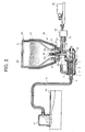
- FIG. 1 and 2 shows a schematic view illustrating an embodiment of the toner feeder arranged in an electrophotographic image forming apparatus of the present invention.
- a toner container 71 is connected to a toner receiver 74 with a toner feeding pipe 72, and a toner is fed to the toner receiver 74 from the toner container 71 with a pressure applied by a powder pump 73.
- a discharge powder pump 73 installed close to the toner container 71 applies a pressure to the toner feeding pipe 72 to feed the toner.
- a suction powder pump installed close to the toner container 71 applies a suction pressure to the toner feeding pipe 72 to feed the toner.
- either the discharge or the suction powder pump can be used to feed the toner.
- the toner container 71 may be detachable with the toner feeding pipe 72.
- a detachable toner cartridge is used as the toner container 71 to simply and conveniently feed new toner.
- the toner container 71 may be fixed. Not only the new toner but also the toner collected by a cleaner on a photoreceptor of the electrophotographic image forming apparatus in the toner container 71 can be used in the present invention.
- a connection point of the toner feeding pipe 72 with the toner container 71 is preferably located on a bottom face thereof because the toner easily enters the toner feeding pipe 72 by gravitation.
- a bottom 75 of the toner container 71 is conically or multi-pyramidically tapered toward the connection point with the toner feeding pipe 72 such that the toner less remains in the toner container 71.
- the toner When air is taken in the toner container 71 or a stirring blade therein stirs the toner, the toner is fluidized and easily enters toner feeding pipe 72. Particularly when air is taken in through an air intake 76 located on the toner feeding pipe 72 close to the toner container 71 as shown in Figs. 1 and 2, the toner stably enters the toner feeding pipe 72.
- the toner feeding pipe 72 can be formed by a material with elasticity or a material without elasticity.
- the toner feeding pipe 72 can flexibly be handled like a rubber tube in an electrophotographic image forming apparatus and can easily be installed therein.
- the toner feeding pipe 72 preferably has an inner cross-sectional area of from 0.05 to 1.00 cm 2 , and more preferably from 0.1 to 0. 5 cm 2 .
- an inner volume thereof is too large for the air or toner amount flown by a powder pump and a pressure in the toner feeding pipe 72 decreases, and therefore the toner is not smoothly fed.
- the toner feeding pipe 72 is too thin, a friction between the toner and an inner wall of the toner feeding pipe 72 becomes large, and therefore the toner is not smoothly fed, either.
- the inner wall of the toner feeding pipe 72 preferably has a high smoothness and less friction resistance to decrease the friction with the toner.
- a cross section of the toner feeding pipe 72 may have any shape, and preferably has a circularity because the inner wall area is small and the toner feeding resistance decreases.
- the toner feeding pipe 72 preferably has a length not longer than 2 m, and more preferably not longer than 1 m.
- numeral 77 is an air filter.
- the powder pump 73 is a discharge pump and the powder pump 73' is a suction pump. Any pumps generating a compression pressure or a suction pressure can be used, and a piston pump with a valve can also be used.
- a powder pump commonly known as a mohno pump using a screw pump having a female screw stator having a double pitch spiral groove inside and a male screw rotor rotatably inserted in the stator is preferably used because it has a simple structure, a small size, does not burden and deteriorate the toner.
- Fig. 4 is a perspective view illustrating a partial cross section of an embodiment of a discharge screw pump of the present invention.
- Fig. 3 is a schematic view illustrating a cross section of an embodiment of the toner feeder of the present invention, including the discharge screw pump.
- a screw pump 1 has a female screw stator 2 formed of an elastic material such as rubbers, which has a double pitch spiral groove inside and a male screw rotor 3 formed of a metal and a resin, etc., which is rotatably inserted in the stator.
- the stator 2 has its periphery covered by a holder 4 supported by a side board 11, and a gap 5 is formed between an inner surface of the holder 4 and a peripheral surface of the stator 2.
- the gap 5 is connected to a toner discharge opening 6 located in the downstream of the rotor 3, and the holder 4 has an air supply opening 7 connected to the gap 5.
- An air supply tube 33 is fitted into the air supply opening 7 from an air pump 30, and air from the air pump 30 is supplied to the toner discharge opening 6 from the air supply opening 7 through the gap 5.
- the rotor 3 is connected to a shaft of a feeding screw 10 with a spring pin 12, etc., and is rotated while the feeding screw 10 is rotated by a drive unit (not shown).
- a discharge pressure is generated to feed the toner fed by the feeding screw 10.
- air is supplied from the air pump 30 to the toner discharge opening 6 from the air supply opening 7 through the gap 5 to fluidize the toner, and smoothly and reliably discharge the toner in the direction of an arrow with a discharge pressure of the screw pump 1.
- a feeding tube 13 having an end fitted into a toner receiver 81 of an image developer 80 and the other end fitted into the toner discharge opening 6.
- the feeding tube 13 is preferably formed of a flexible rubber tube having an inner diameter of from 3 to 7 mm, such as polyurethane, nitrile, EPDM and silicone. Free piping can be made with the flexible tube.
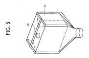
- a toner container 20 is a bag-in-box type container including an outer box 21 as a protection case and a flexible and deformable toner bag 22 detachably contained in the outer box 21.
- the outer box 21 is formed of a paper with a stiffness, a cardboard, a resin, etc. and has an inner space so as to contain the toner bag 22 leaving no space therebetween.
- the toner container 20 not only protects the flexible toner bag 22 containing the toner in the outer box 21 but also improves easiness of handling and storing the container.
- the toner bag 22 is a closed bag without air out or in, which is formed of a single layer or a multilayer of a flexible sheet material such as polyester and polyethylene films having a thickness of from about 80 to 125 ⁇ m.
- the toner bag 22 has a toner discharge hole 24 on the bottom, which is fixed by a mouth piece 23 formed of resins such as polyethylene and nylon.
- the toner discharge hole 24 fixed by the mouth piece 23 has a single layer or a multilayer seal 25 having a role of a self-closing valve.
- the seal 25 is formed of an elastic material such as unbreathable foam sponges.
- the toner bag 22 is tapered toward the toner discharge hole 24 such that the toner does not remain.
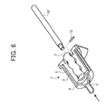
- a setting portion 50 where the toner container is installed has a container holder 51 and a nozzle 52 inserted into the seal 25.
- the nozzle 52 is a linear cylinder having a socket 54 following to a tip 53.
- the nozzle 52 has a single-lumen structure inside, having a toner route 55 following to the socket 54.
- a case 14 is formed to temporarily store the toner.
- the side board forms a part of the case 14.
- a filter 15 preventing increase of the pressure therein is formed and the feeding screw 10 is located therein.
- Air is supplied to the toner container 20 from the air pump 30 through an air tube 31 and the nozzle 52.
- the air supplied in the toner container 20 stirs and fluidized the toner therein, prevents a bridge phenomenon of the toner and decreases a residual amount of the toner in the container.
- a breathable filter 26 can be formed on top of the toner container 20.
- the breathable filter 26 can prevents a pressure in the toner container 20 from returning to normal.
- the air pump 30 has a selector valve 32 before the toner container 20 and the screw pump 1 to supply air to both thereof.
- the thus structured toner feeder is used as a toner feeding apparatus feeding a toner to the image developer 80.
- Fig. 6 is a perspective view illustrating a partial cross section of an embodiment of a suction screw pump of the present invention.
- the suction screw pump 1' in Fig. 6 is a same discharge screw pump in Fig. 4 except that the feeding screw 10 is replaced by a shaft 10' and the holder 4 does not have the air supply opening 7.
- the shaft 10' is rotated in the reverse direction of the feeding screw 10 to generate a suction pressure at a toner suction opening 6.
- the toner suctioned from the toner suction opening 6 is discharged in the direction of the shaft 10'.
- the rotor 3 and stator 2 have reverse winding directions.
- the above-mentioned uniaxial eccentric screw pump has the stator 2 made of a rubber, in which the metallic or resin rotor 3 rotates while frictionizes the stator 2 inside. Therefore, an inner diameter of the stator 2 is gradually expanded due to an abrasion as time passes and the discharge or suction pressure thereof decreases.
- Fig. 7 is a schematic view illustrating a cross section of the screw pump of the present invention, in which the rotor 3 is inserted into the stator 2.
- Each D1, D2 and D3 is used as an interlocking amount between the rotor 3 and stator 2 as a matter of convenience.
- D1 is an interlocking amount between a cross section of the rotor 3 and a minimum inner diameter of the stator 2.
- D3 is an interlocking amount between the cross section of the rotor 3 and an end R of the stator 2.
- D2 is an interlocking amount between a spiral outer diameter of the rotor 3 and an inner diameter of the stator 2.
- interlocking amounts D1, D2 and D3 are essential for the discharge and suction pressure of the screw pumps 1 and 1' respectively.
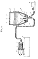
- Fig. 8 is a schematic view illustrating a cross section of an embodiment of the toner feeder of the present invention, including the suction screw pump in Fig. 6.
- the toner feeder has a same structure as the toner feeder in Fig. 3 except that the pump is located at the toner receiver 81 of the image developer 80 and the holder 4 does not have an air supply opening 7.
- the toner for use in the present invention preferably has an aggregation not greater than 20 % and a circularity not les than 0.93, and more preferably an aggregation not greater than 15 % and a circularity not les than 0.95.
- the aggregation and circularity are measured as follows.
- a sieve S1 having an opening of 150 ⁇ m, a sieve S2 having an opening of 75 ⁇ m and a sieve S3 having an opening of 45 ⁇ m are lined in this order from above.
- 2 g of a toner are put on the sieve S1 having an opening of 150 ⁇ m and vibrated for 30 sec at an amplitude of 1mm to measure each weight W1, W2 and W3 of the toner remaining on each of the sieves S1, S2 and S3.
- the circularity is measured by a flow-type particle image analyzer FPIA-2000 from SYSMEX CORPORATION.
- the toner is diluted by distilled water, and a detergent DRYWELL from Fuji Photo Film Co., Ltd. is added to the mixture and the mixture is dispersed by an ultrasonic washer.
- the circularity is determined by dividing a peripheral length equivalent to a projected area of the toner with a peripheral length P of a projection image of the toner.
- the flow-type particle image analyzer FPIA-2000 from SYSMEX CORPORATION automatically reads and processes projection images of not less than 1,000 toners to determine an average. Namely, the circularity is 1 or less. The closer to 1, the closer to a sphere. The smaller, the more angular.
- the aggregation is a standard to see aggregation between powders. The lower, the more difficult to aggregate.
- the aggregation is typically related with fluidity of the powder. The lower the aggregation, the better the fluidity. As a matter of course, as the toner is transported in a long tube, the better the fluidity, the better the powder transportation without blockage thereof. However, only the good fluidity is not sufficient and the circularity is essential in the present invention.
- the toner in the toner feeding tube is tightly packed because a bulk thereof becomes small due to a discharge, a suction pressure or a supply air.
- the toners tangle each other (concavities and convexities of the toners are engaged each other) and become difficult to break. Therefore, the toner blockage is a made in the toner feeding tube and has a fatal influence upon a whole system. Even when the toner blockage is not made, transport resistance of the toner becomes large and transport speed thereof largely changes, resulting in difficulty or instability of controlling the system.
- the toner amount according to an output power of the powder pump is stably transported.
- the toner concentration in a two-component image developer which needs controlling the toner concentration can be controlled by adjusting the operation time of the powder pump.
- the powder pump through which the toner passes needs closeness to generate a pressure and the toner is necessarily frictionized with a part thereof. Some toners are stuck in the frictionized part and deteriorate. The deteriorated toner is not charged well in an image developer and causes foggy images.
- the toner of the present invention having an aggregation not greater than 20% and a circularity not less than 0. 94 can prevent the foggy image. It is considered that this is because the toner having a shape close to a sphere and a low aggregation easily tumbles and is difficult to be stuck in the frictionized part of the powder pump.
- a method of adding an external additive is effectively used to make the aggregation of the resultant toner not greater than 20%.
- an inorganic material having a particle size not greater than 0.1 ⁇ m and a hydrophobized surface is preferably used as the external additive to make the aggregation of the resultant toner small.
- the method is not limited thereto to make the aggregation of the resultant toner small in the present invention.
- a pulverization method thereof needs to be controlled when the toner is a pulverized toner.
- a method of heating the toner can also be used to make the toner close to a sphere.
- a polymerization method of producing a toner typically includes a process of shaping the toner, in which a circularity of the resultant toner can be controlled.
- the typical pulverized toner has a circularity not greater than 0.92.
- the toner for use in the present invention is a dry toner capable of being used for both a one-component developer and a two-component developer, and has a volume-average particle diameter of from 3 to 15 ⁇ m.
- the toner of the present invention typically includes a binder resin and a colorant, and optionally includes a charge controlling agent, a wax, a magnetic material, an external additive, etc.
- binder resins for use in the present invention include styrene polymers and substituted styrene polymers such as polystyrene, poly-p-chlorostyrene and polyvinyltoluene; styrene copolymers such as styrene-p-chlorostyrene copolymers, styrene-propylene copolymers, styrene-vinyltoluene copolymers, styrene-vinylnaphthalene copolymers, styrene-methyl acrylate copolymers, styrene-ethyl acrylate copolymers, styrene-butyl acrylate copolymers, styrene-octyl acrylate copolymers, styrene-methyl methacrylate copolymers, styrene-ethyl methacryl
- colorants for use in the toner of the present invention include any known dyes and pigments such as carbon black, Nigrosine dyes, black iron oxide, Naphthol Yellow S, Hansa Yellow (10G, 5G and G), Cadmium Yellow, yellow iron oxide, loess, chrome yellow, Titan Yellow, polyazo yellow, Oil Yellow, Hansa Yellow (GR, A, RN and R), Pigment Yellow L, Benzidine Yellow (G and GR) , Permanent Yellow (NCG) , Vulcan Fast Yellow (5G and R), Tartrazine Lake, Quinoline Yellow Lake, Anthrazane Yellow BGL, isoindolinone yellow, red iron oxide, red lead, orange lead, cadmium red, cadmiummercuryred, antimony orange, Permanent Red 4R, Para Red, Fire Red, p-chloro-o-nitroaniline red, Lithol Fast Scarlet G, Brilliant Fast Scarlet, Brilliant Carmine BS, Permanent Red (F2R, F4R, FRL, FRLL and F4
- the content of the colorant in the toner is preferably from 0 to 50 parts by weight per 100 parts by weight of the binder resin.
- a content of polar solvent soluble constituents in impurities included in the pigment is preferably small.
- the toner of the present invention may optionally include a charge controlling agent.
- the charge controlling agent include any known charge controlling agents such as Nigrosine dyes, triphenylmethane dyes, metal complex dyes including chromium, chelate compounds of molybdic acid, Rhodamine dyes, alkoxyamines, quaternary ammonium salts (including fluorine-modified quaternary ammonium salts), alkylamides, phosphor and compounds including phosphor, tungsten and compounds including tungsten, fluorine-containing activators, metal salts of salicylic acid, salicylic acid derivatives, etc.
- the content of the charge controlling agent is determined depending on the species of the binder resin used, whether or not an additive is added and toner manufacturing method (such as dispersion method) used, and is not particularly limited.
- the content of the charge controlling agent is typically from 0.1 to 10 parts by weight, and preferably from 0.2 to 5 parts by weight, per 100 parts by weight of the binder resin included in the toner.
- the content is too high, the toner has too large charge quantity, and thereby the electrostatic force of a developing roller attracting the toner increases, resulting in deterioration of the fluidity of the toner and decrease of the image density of toner images.
- the charging controlling agents include many polar solvent soluble constituents in their main components or impurities. Materials including less polar solvent soluble constituents are preferably used for the charge controlling agents to decrease polar solvent soluble constituents in the resultant toner.
- the toner of the present invention may optionally include an external additive.
- an external additive Any known inorganic fine particles and hydrophobized inorganic fine particles can be used as external additives.
- Specific examples of the external additives include silicafine particles, hydrophobized silica, fatty acid metallic salts such as zinc stearate and aluminium stearate, metal oxides such as titania, alumina, tin oxide and antimony oxide, fluoropolymers, etc.
- hydrophobized silica, titania and alumina fine particles are preferably used.
- silica fine particles include HDK H 2000, HDK H 2000/4, HDK H 2050EP and HVK21 from Hoechst AG; andR972, R974, RX200, RY200, R202, R805 and R812 from Nippon. Aerosil Co.
- titania fine particles include P-25 from Nippon Aerosil Co.; ST-30 and STT-65C-S from Titan Kogyo K.K.; TAF-140 from Fuji Titanium Industry Co., Ltd.; MT150W, MT-500B and MT-600b from Tayca Corp., etc.
- hydrophobized titanium oxide fine particles include T-805 from Nippon Aerosil Co.; STT-30A and STT-65S-S from Titan Kogyo K. K. ; TAF-500T and TAF-1500T from Fuj i Titanium Industry Co., Ltd.; MT-100S and MT100T from Tayca Corp.; IT-S from Ishihara Sangyo Kaisha Ltd., etc.
- hydrophobized silica fine particles titania fine particles or alumina fine particles, hydrophilic fine particles are subjected to silane coupling agents such as methyltrimethoxy silane, methyltriethoxy silane and octylmethoxy silane.
- silane coupling agents such as methyltrimethoxy silane, methyltriethoxy silane and octylmethoxy silane.
- Inorganic fine particles optionally subjected to a silicone oil upon application of heat is preferably used.
- silicone oil examples include dimethyl silicone oil, methylphenyl silicone oil, chlorphenyl silicone oil, methylhydrogen silicone oil, alkyl modified silicone oil, fluorine modified silicone oil, polyether modified silicone oil, alcoholmodifiedsiliconeoil, aminomodifiedsiliconeoil, epoxy modified silicone oil, epoxy-polyether modified silicone oil, phenol modified silicone oil, carboxyl modified silicone oil, mercapto modified silicone oil, acryl modified silicone oil, methacryl modified silicone oil, ⁇ -methylstyrene modified silicone oil, etc.
- the inorganic fine particles include silica, alumina, titanium oxide, barium titanate, magnesium titanate, calcium titanate, strontium titanate, zinc oxide, tin oxide, quartz sand, clay, mica, sand-lime, diatom earth, chromium oxide, cerium oxide, red iron oxide, antimony trioxide, magnesium oxide, zirconium oxide, barium sulfate, barium carbonate, calcium carbonate, silicon carbide, silicon nitride, etc.
- the silica and titanium dioxide are preferably used.
- a content of the inorganic fine particles is preferably from 0.1 to 5 % by weight, and more preferably from 0.3 to 3 % by weight based on total weight of the toner.
- the toner or developer of the present invention preferably includes a wax to have releasability.
- the wax preferably has a melting point of from 40 to 10°C, and more preferably from 50 to 110°C. When the melting point is too high, low-temperature fixability of the resultant toner is occasionally insufficient. When the melting point is too low, offset resistance and durability of the resultant toner occasionally deteriorates.
- the melting point of the wax can be measure by a differential scanning calorimeter. Namely, a melting peak point of a sample of a few mg heated at a specific programming speed such as 10 °C /min is a melting point.
- a content of the wax is preferably from 0 to 20 parts by weight, and more preferably from 0 to 10 parts by weight.
- the wax examples include a solid paraffin wax, a micro wax, a rice wax, a fatty acid amide wax, a fatty acid wax, aliphatic mono ketone, a fatty acid metal salt wax, a fatty acid ester wax, a partially saponified fatty acid ester was, a silicone varnish, higher alcohol, a carnauba wax, etc.
- Polyolefin such as low-molecular-weight polyethylene and polypropylene can also be used.
- the polyolefin preferably has a melting point of from 70 to 150 °C, and more preferably from 120 to 150 °C when measured by a ring and ball method.
- a cleanability improver is preferably included in the toner or developer or added to a surface thereof to remove the toner or developer remaining on a photoreceptor and a first transfer medium after transfer.
- the cleanability improvers include fatty acid metal salts such as zinc stearate, sodium stearate and stearic acids; and polymer fine particles formed by a soap-free emulsifying polymerization method, such as polymethylmethacrylate fine particles and polystyrene fine particles.
- the polymer fine particles preferably has a comparatively narrow particle diameter distribution and a volume-average particle diameter of from 0.01 to 1 ⁇ m.
- a content of the cleanability improver is preferably from 0 to 5 parts by weight, and more preferably from 0 to 1 parts by weight.
- the toner of the present invention may include a magnetic material and can be used as a magnetic toner. Magnetic fine particles are included in the toner particles to prepare a magnetic toner.
- the specific examples of the magnetic materials include ferromagnetic metals or metal alloys such as irons such as ferrite and magnetite, nickel and cobalt or compounds including these elements; metal alloys without ferromagnetic elements, which become ferromagnetic when properly heated and are named Heusler alloys including manganese and copper such as manganese-copper-aluminium and manganese-copper tin; chromium dioxide, etc.
- the magnetic material is uniformly dispersed and included as a fine powder having an average particle diameter of from 0.1 to 1 ⁇ m.
- a content of the magnetic material is preferably from 10 to 70 parts by weight, and more preferably 20 to 50 parts by weight per 100 parts by weight of the toner.
- the mixture was kneaded upon application of heat by a two-roll mixer and extended upon application of pressure and cooled to prepare a mixture 1.
- the mixture 1 was pulverized by a pulverizer I-type mill using a collision board with a jet mill from Nippon Pneumatic Mfg. Co., Ltd., and classified by a spiral flow wind-force DS classifier from Nippon Pneumatic Mfg. Co., Ltd. to prepare a powder 1 having a volume-average particle diameter of about 6 ⁇ m.
- 1.0 % by weight of a hydrophobic silica H2000 from Clariant (Japan) KK was mixed by a mixer with the powder 1 to prepare a toner 1.
- Example 2 The procedures of preparation for the toner 1 in Example 1 were repeated except for changing the hydrophobic silica to silica treated with an silicone oil RY50 from Nippon Aerosil Co. to prepare a toner 2.
- Example 1 The procedures of preparation for the toner 1 in Example 1 were repeated except for changing the pulverizer to a mechanical pulverizer Turbo Mill from TUROBO KOGYO CO., LTD. to prepare a toner 3.
- Example 3 The procedures of preparation for the toner 3 in Example 3 were repeated except for changing the hydrophobic silica to silica treated with an silicone oil RY50 from Nippon Aerosil Co. to prepare a toner 4.
- the particulate dispersion liquid 1 was measured by LA-920 to find a volume-average particle diameter thereof was 105 nm.
- Apart of the particulate dispersion liquid 1 was dried to isolate a resin component therefrom.
- the resin component had a Tg of 59 °C and a weight-average molecular weight of 150,000.
- the prepolymer 1 includes a free isocyanate in an amount of 1.53 % by weight.
- ketimine compound 1 170 parts of isophorondiamine and 75 parts of methyl ethyl ketone were reacted at 50 °C for 5 hrs in a reaction vessel including a stirrer and a thermometer to prepare a [ketimine compound 1].
- the ketimine compound 1 had an amine value of 418.
- the low-molecular-weight polyester 1 had a number-average molecular weight of 2,500, a weight-average molecular weight of 6,700, a Tg of 43 °C and an acid value of 25.
- 1,200 parts of water, 540 parts of carbon black Pintex 35 having a n oil absorption of 42 ml/100 mg and a pH of 9.5 from degussa AG, 1,200 parts of a polyester resin were mixed by a Henschel mixer from Mitsui Mining Co., Ltd. After the mixture was kneaded upon application of heat by a two-roll mill at 150 °C for 3 min, the mixture was extended upon application of pressure and pulverized by a pulverizer to prepare a master batch 1.
- 378 parts of the low-molecular-weight polyester 1, 110 parts of carnauba wax, 22 parts of charge controlling agent (salicylic acid metal complex E-84 from Orient Chemical Industries Co., Ltd.) and 947 parts of ethyl acetate were mixed in a reaction vessel including a stirrer and a thermometer. The mixture was heated to have a temperature of 80 °C while stirred. After the temperature of 80 °C was maintained for 5 hrs, the mixture was cooled to have a temperature of 30 °C in an hour. Then, 500 parts of the master batch 1 and 500 parts of ethyl acetate were added to the mixture and mixed for 1 hr to prepare a material solution 1.
- 1, 324 parts of the material solution 1 were put in another container, the carbon black and wax were dispersed using a beads mill Ultra Visco Mill from IMECS CO., LTD., at a liquid feeding speed of 1 kg/hr and a disc peripheral speed of 6m/sec and three passes, in which 0.5 mm zirconia beads are used at 80 % by volume.
- 1,324 parts of an ethyl acetate solution of the low-molecular-weight polyester 1 having a concentration of 65 % were added to the material solution 1 and the mixture was stirred by the beads mill once in the same conditions to prepare a[ pigment/wax dispersion liquid 1] .
- the pigment/ wax dispersion liquid 1 had a concentration of a solid content of 50 % at 130 °C for 30 min.
- the emulsified slurry 1 was put in a vessel including a stirrer and a thermometer. After a solvent was removed from the emulsified slurry 1 at 30 °C for 8 hrs, the slurry was aged at 45 °C for 4 hrs to prepare a dispersion slurry 1.
- the dispersion slurry 1 had a volume-average particle diameter of 5.99 ⁇ m, and a number-average particle diameter of 5.70 ⁇ m when measured by Multisizer II.
- Example 5 The procedures of preparation for the toner 5 in Example 5 were repeated except for changing the hydrophobic silica to silica treated with an silicone oil RY50 from Nippon Aerosil Co. to prepare a toner 6.
- Example 5 The procedures of preparation for the toner 5 in Example 5 were repeated except for increasing the rotational speed of the T.K. homomixer and a temperature when the solvent is removed to prepare a toner 7 having a smaller circularity.
- Example 7 The procedures of preparation for the toner 7 in Example 7 were repeated except for changing the hydrophobic silica to silica treated with an silicone oil RY50 from Nippon Aerosil Co. to prepare a toner 8.
- Toner 2 35 0.915 ⁇ ⁇ Ex. 3 Toner 3 11 0.942 ⁇ o ⁇ Ex. 4 Toner 4 32 0.942 ⁇ ⁇ Ex. 5 Toner 5 14 0.973 ⁇ o ⁇ Ex. 6 Toner 6 27 0.973 ⁇ ⁇ Ex. 7 Toner 7 18 0.895 ⁇ ⁇ Ex. 8 Toner 8 32 0.896 ⁇ ⁇ Toner Before fed After fed by the feeder in Fig. 3 After fed by the feeder in Fig. 8 Ex. 1 Toner 1 0.00 0.05 0.03 Ex. 2 Toner 2 0.05 - - Ex. 3 Toner 3 0.00 0.00 0.00 Ex. 4 Toner 4 0.05 0.11 0.08 Ex. 5 Toner 5 0.00 0.00 0.00 Ex. 6 Toner 6 0.05 0.21 0.07 Ex. 7 Toner 7 0.00 0.16 0.06 Ex. 8 Toner 8 0.05 - 0.21
- Each of the toners 3 and 5 having an aggregation of not greater than 20 % and a circularity not less than 0.93 could stably fed in the toner feeder in Fig. 3, and also could stably fed in the toner feeder in Fig. 8 and an operation time, i.e., 0.1 to 1 sec of the powder pump was almost proportional to a fed amount of the toner. No foggy image was produced before and after the toner was fed.
- each toner 1 and 7 having an aggregation of not greater than 20 % but a circularity less than 0.93 in a bottle could fed in the toner feeders in Figs. 3 and 8, but the toner feeding occasionally stopped. No foggy image was produced before the toner was fed, but foggy images were produced after fed.
- all of each toner 4 and 6 having a circularity not less than 0. 93 but an aggregation of greater than 20 % in a bottle could fed in the toner feeders in Figs. 3 and 8, but the toner feeding occasionally stopped. Foggy images were produced before the toner was fed, and foggy images became worse after fed.
- Each of the toners 2 and 8 having a different aggregation % and a different circularity from those of the present invention could not fed at all in the toner feeder in Fig. 3, and toner blockage was made in the tube and the toner cold not fed on the way in the toner feeder in Fig. 8. Foggy images were produced before the toner was fed, and foggy images became worse after fed.
Abstract
Description
- The present invention relates to an image forming apparatus such as printers, facsimiles and copiers using electrophotographic image forming methods, and more particularly to a toner feeder, a toner, and an electrophotographic image forming apparatus using the toner feeder and toner.
- For example, the following toner feeding methods are conventionally known:
- (1) a method of feeding a toner with a coil screw arranged in a pipe formed between a sender and a receiver; (2) a method of feeding a toner mostly by gravity while closely locating a sender and a receiver above and below; and (3) a method of feeding a toner from a sender to receiver optionally located through a pipe with a pressure applied by a powder pump, as disclosed in, e.g., Japanese Laid-Open Patent Publications Nos. 2002-139906 and 2002-139902.
-
- Each of the above-mentioned (1) and (2) has a large limitation to a location of the sender and receiver, and have many problems such as unsuitableness for a long-distance feeding. Now, the above-mentioned toner feeding method (3) having fewer such problems attracts attention. Particularly, as an electrophotographic image forming apparatus has a large volume of a toner container, the toner feeding method (3) can enlarge layout freedom and save space of a place where the electrophotographic image forming apparatus is used. Particularly, a full-color electrophotographic image forming apparatus using 4 color toners and the toner feeding method (3) has an advantage in terms of the layout and space-saving.
- However, even the toner feeding method (3) does not always have no problem. As a sender and a receiver are connected with a pipe, etc., it is probable that a toner blockage in the pipe occurs. When the toner blockage occurs, a toner cannot be fed, resulting in a fatal problem for a whole system. The pipe needs to be shortened to prevent occurrence of the toner blockage, resulting a limitation to the layout freedom. In addition, even though the toner feeding method (3) does not have the toner blockage problem, it has an unstable toner feeding speed, resulting in a problem of complicated control thereof. Further, when the toner passes through the powder pump, the toner deteriorates due to friction therewith and produces foggy images
- Because of these reasons, a need exists for a toner feeder, a toner and an electrophotographic image forming apparatus using the toner feeder and toner, which enlarge layout freedom and simply control feeding a stable amount of a toner without toner blockage.
- Accordingly, an object of the present invention is to provide a toner feeder, a toner and an electrophotographic image forming apparatus using the toner feeder and toner, which enlarge layout freedom and simply control feeding a stable amount of a toner without toner blockage and without producing foggy images.
- Briefly this object and other objects of the present invention as hereinafter will become more readily apparent can be attained by a toner having an aggregation not greater than 20 % and a circularity not less than 0.93.
- In another aspect of the present invention, a toner feeder is provided, which includes a container containing the toner; a pipe feeding the toner through; and a pump feeding the toner from the container.
- In yet another aspect of the present invention, an electrophotographic image forming apparatus including the toner feeder is provided.
- These and other objects, features and advantages of the present invention will become apparent upon consideration of the following description of the preferred embodiments of the present invention taken in conjunction with the accompanying drawings.
- Various other objects, features and attendant advantages of the present invention will be more fully appreciated as the same becomes better understood from the detailed description when considered in connection with the accompanying drawing (s) in which like reference characters designate like corresponding parts throughout and wherein:
- Fig. 1 is a schematic view illustrating an embodiment of the toner feeder of the present invention, using a discharge powder pump;
- Fig. 2 is a schematic view illustrating an embodiment of the toner feeder of the present invention, using a suction powder pump;
- Fig. 3 is a schematic view illustrating a cross section of an embodiment of the toner feeder of the present invention, in which a discharge screw pump is arranged;
- Fig. 4 is a perspective view illustrating a partial cross section of an embodiment of a discharge screw pump arranged in the toner feeder of the present invention;
- Fig. 5 is a perspective view illustrating a toner container in the toner feeder of the present invention for explaining a breathable filter formed in the toner container;
- Fig. 6 is a perspective view illustrating a partial cross section of an embodiment of a suction screw pump arranged in the toner feeder of the present invention;
- Fig. 7 (A, B and C) is a schematic view illustrating a cross section of the screw pump of the present invention, in which a rotor is inserted into a stator; and
- Fig. 8 is a schematic view illustrating a cross section of an embodiment of the toner feeder of the present invention, in which a suction screw pump is arranged.
-
- Generally, the present invention provides a toner feeder, a toner and an electrophotographic image forming apparatus using the toner feeder and toner, which enlarge layout freedom and simply control feeding a stable amount of a toner without toner blockage and without producing foggy images.
- The toner feeder of the present invention has a large layout freedom, can freely be handled in an electrophotographic image forming apparatus and can simply be installed therein. In addition, the toner feeder has a simple structure and can be downsized to save space, and deteriorates a toner less because of giving less stress thereto.
- The toner of the present invention having a small aggregation has good fluidity, and can be fed through a long feeding pipe without blockage thereof. In addition, the toner of the present invention having a specific circularity can avoid packing (concavities and convexities of the toners engage with one another) in the feeding pipe and the toner blockage therein does not occur. Further, the toner has less concavity and convexity and a feeding speed thereof becomes stable. Even when a two-component developer is used, a toner concentration in an image developer can be controlled by an operation time of a powder pump because of the stability of the feeding speed.
- The electrophotographic image forming apparatus of the present invention has a large layout freedom, and can simply and stably feed a toner without the toner blockage. In addition, even when a two-component developer is used, a toner concentration in an image developer can be controlled by an operation time of a powder pump because of the stability of the feeding speed.
- Hereinafter, embodiments of the present invention will be explained, referring to the drawings.
- Each of the Figs. 1 and 2 shows a schematic view illustrating an embodiment of the toner feeder arranged in an electrophotographic image forming apparatus of the present invention.
- In Figs. 1 and 2, a
toner container 71 is connected to atoner receiver 74 with atoner feeding pipe 72, and a toner is fed to thetoner receiver 74 from thetoner container 71 with a pressure applied by apowder pump 73. In Fig. 1, adischarge powder pump 73 installed close to thetoner container 71 applies a pressure to thetoner feeding pipe 72 to feed the toner. In Fig. 2, a suction powder pump installed close to thetoner container 71 applies a suction pressure to thetoner feeding pipe 72 to feed the toner. In the present invention, either the discharge or the suction powder pump can be used to feed the toner. - The
toner container 71 may be detachable with thetoner feeding pipe 72. In an electrophotographic image forming apparatus, a detachable toner cartridge is used as thetoner container 71 to simply and conveniently feed new toner. As a matter of course, thetoner container 71 may be fixed. Not only the new toner but also the toner collected by a cleaner on a photoreceptor of the electrophotographic image forming apparatus in thetoner container 71 can be used in the present invention. - A connection point of the
toner feeding pipe 72 with thetoner container 71 is preferably located on a bottom face thereof because the toner easily enters thetoner feeding pipe 72 by gravitation. Abottom 75 of thetoner container 71 is conically or multi-pyramidically tapered toward the connection point with thetoner feeding pipe 72 such that the toner less remains in thetoner container 71. - When air is taken in the
toner container 71 or a stirring blade therein stirs the toner, the toner is fluidized and easily enterstoner feeding pipe 72. Particularly when air is taken in through anair intake 76 located on thetoner feeding pipe 72 close to thetoner container 71 as shown in Figs. 1 and 2, the toner stably enters thetoner feeding pipe 72. - The
toner feeding pipe 72 can be formed by a material with elasticity or a material without elasticity. When thetoner feeding pipe 72 is formed by an elastic rubber, thetoner feeding pipe 72 can flexibly be handled like a rubber tube in an electrophotographic image forming apparatus and can easily be installed therein. - The
toner feeding pipe 72 preferably has an inner cross-sectional area of from 0.05 to 1.00 cm2, and more preferably from 0.1 to 0. 5 cm2. When thetoner feeding pipe 72 is too thick, an inner volume thereof is too large for the air or toner amount flown by a powder pump and a pressure in thetoner feeding pipe 72 decreases, and therefore the toner is not smoothly fed. When thetoner feeding pipe 72 is too thin, a friction between the toner and an inner wall of thetoner feeding pipe 72 becomes large, and therefore the toner is not smoothly fed, either. The inner wall of thetoner feeding pipe 72 preferably has a high smoothness and less friction resistance to decrease the friction with the toner. A cross section of thetoner feeding pipe 72 may have any shape, and preferably has a circularity because the inner wall area is small and the toner feeding resistance decreases. In addition, thetoner feeding pipe 72 preferably has a length not longer than 2 m, and more preferably not longer than 1 m. In Figs. 1 and 2, numeral 77 is an air filter. - Next, powder pumps 73 and 73' in Figs. 1 and 2 will be explained.
- The
powder pump 73 is a discharge pump and the powder pump 73' is a suction pump. Any pumps generating a compression pressure or a suction pressure can be used, and a piston pump with a valve can also be used. - In the present invention, a powder pump commonly known as a mohno pump using a screw pump having a female screw stator having a double pitch spiral groove inside and a male screw rotor rotatably inserted in the stator, is preferably used because it has a simple structure, a small size, does not burden and deteriorate the toner.
- Embodiments of pumps for use in the present invention will be explained, referring to the drawings. Fig. 4 is a perspective view illustrating a partial cross section of an embodiment of a discharge screw pump of the present invention. Fig. 3 is a schematic view illustrating a cross section of an embodiment of the toner feeder of the present invention, including the discharge screw pump. In Figs. 3 and 4, a
screw pump 1 has afemale screw stator 2 formed of an elastic material such as rubbers, which has a double pitch spiral groove inside and amale screw rotor 3 formed of a metal and a resin, etc., which is rotatably inserted in the stator. Thestator 2 has its periphery covered by aholder 4 supported by aside board 11, and agap 5 is formed between an inner surface of theholder 4 and a peripheral surface of thestator 2. Thegap 5 is connected to atoner discharge opening 6 located in the downstream of therotor 3, and theholder 4 has anair supply opening 7 connected to thegap 5. Anair supply tube 33 is fitted into theair supply opening 7 from anair pump 30, and air from theair pump 30 is supplied to the toner discharge opening 6 from theair supply opening 7 through thegap 5. - The
rotor 3 is connected to a shaft of a feedingscrew 10 with aspring pin 12, etc., and is rotated while the feedingscrew 10 is rotated by a drive unit (not shown). When therotor 3 rotates, a discharge pressure is generated to feed the toner fed by the feedingscrew 10. Then, air is supplied from theair pump 30 to the toner discharge opening 6 from theair supply opening 7 through thegap 5 to fluidize the toner, and smoothly and reliably discharge the toner in the direction of an arrow with a discharge pressure of thescrew pump 1. - A feeding
tube 13 having an end fitted into atoner receiver 81 of animage developer 80 and the other end fitted into thetoner discharge opening 6. The feedingtube 13 is preferably formed of a flexible rubber tube having an inner diameter of from 3 to 7 mm, such as polyurethane, nitrile, EPDM and silicone. Free piping can be made with the flexible tube. Atoner container 20 is a bag-in-box type container including anouter box 21 as a protection case and a flexible anddeformable toner bag 22 detachably contained in theouter box 21. Theouter box 21 is formed of a paper with a stiffness, a cardboard, a resin, etc. and has an inner space so as to contain thetoner bag 22 leaving no space therebetween. Thetoner container 20 not only protects theflexible toner bag 22 containing the toner in theouter box 21 but also improves easiness of handling and storing the container. - The
toner bag 22 is a closed bag without air out or in, which is formed of a single layer or a multilayer of a flexible sheet material such as polyester and polyethylene films having a thickness of from about 80 to 125 µm. Thetoner bag 22 has atoner discharge hole 24 on the bottom, which is fixed by amouth piece 23 formed of resins such as polyethylene and nylon. Thetoner discharge hole 24 fixed by themouth piece 23 has a single layer or amultilayer seal 25 having a role of a self-closing valve. Theseal 25 is formed of an elastic material such as unbreathable foam sponges. Thetoner bag 22 is tapered toward thetoner discharge hole 24 such that the toner does not remain. - A setting
portion 50 where the toner container is installed has acontainer holder 51 and anozzle 52 inserted into theseal 25. Thenozzle 52 is a linear cylinder having asocket 54 following to atip 53. Thenozzle 52 has a single-lumen structure inside, having atoner route 55 following to thesocket 54. At the lower end of thetoner route 55, acase 14 is formed to temporarily store the toner. The side board forms a part of thecase 14. On top of thecase 14, a filter 15 preventing increase of the pressure therein is formed and the feedingscrew 10 is located therein. - Air is supplied to the
toner container 20 from theair pump 30 through anair tube 31 and thenozzle 52. The air supplied in thetoner container 20 stirs and fluidized the toner therein, prevents a bridge phenomenon of the toner and decreases a residual amount of the toner in the container. As Fig. 5 shows, abreathable filter 26 can be formed on top of thetoner container 20. Thebreathable filter 26 can prevents a pressure in thetoner container 20 from returning to normal. Theair pump 30 has aselector valve 32 before thetoner container 20 and thescrew pump 1 to supply air to both thereof. - The thus structured toner feeder is used as a toner feeding apparatus feeding a toner to the
image developer 80. - Fig. 6 is a perspective view illustrating a partial cross section of an embodiment of a suction screw pump of the present invention.
- The suction screw pump 1' in Fig. 6 is a same discharge screw pump in Fig. 4 except that the feeding
screw 10 is replaced by a shaft 10' and theholder 4 does not have theair supply opening 7. Whensame rotor 3 andstator 2 in thedischarge screw pump 1 are used, the shaft 10' is rotated in the reverse direction of the feedingscrew 10 to generate a suction pressure at atoner suction opening 6. The toner suctioned from thetoner suction opening 6 is discharged in the direction of the shaft 10'. When the shaft 10' is rotated in the same direction of the feedingscrew 10, therotor 3 andstator 2 have reverse winding directions. - The above-mentioned uniaxial eccentric screw pump has the
stator 2 made of a rubber, in which the metallic orresin rotor 3 rotates while frictionizes thestator 2 inside. Therefore, an inner diameter of thestator 2 is gradually expanded due to an abrasion as time passes and the discharge or suction pressure thereof decreases. - Fig. 7 (A, B and C) is a schematic view illustrating a cross section of the screw pump of the present invention, in which the
rotor 3 is inserted into thestator 2. Each D1, D2 and D3 is used as an interlocking amount between therotor 3 andstator 2 as a matter of convenience. D1 is an interlocking amount between a cross section of therotor 3 and a minimum inner diameter of thestator 2. D3 is an interlocking amount between the cross section of therotor 3 and an end R of thestator 2. D2 is an interlocking amount between a spiral outer diameter of therotor 3 and an inner diameter of thestator 2. In the present invention, interlocking amounts D1, D2 and D3 are essential for the discharge and suction pressure of the screw pumps 1 and 1' respectively. - Fig. 8 is a schematic view illustrating a cross section of an embodiment of the toner feeder of the present invention, including the suction screw pump in Fig. 6. When the suction screw pump is used, the toner feeder has a same structure as the toner feeder in Fig. 3 except that the pump is located at the
toner receiver 81 of theimage developer 80 and theholder 4 does not have anair supply opening 7. - Next, the toner for use in the present invention will be explained.
- The toner for use in the present invention preferably has an aggregation not greater than 20 % and a circularity not les than 0.93, and more preferably an aggregation not greater than 15 % and a circularity not les than 0.95. The aggregation and circularity are measured as follows.
- On a powder tester from Hosokawa Micron Corp., a sieve S1 having an opening of 150 µm, a sieve S2 having an opening of 75 µm and a sieve S3 having an opening of 45 µm are lined in this order from above. 2 g of a toner are put on the sieve S1 having an opening of 150 µm and vibrated for 30 sec at an amplitude of 1mm to measure each weight W1, W2 and W3 of the toner remaining on each of the sieves S1, S2 and S3. Then, the aggregation AG (%) is determined by the following formula:
- The circularity is measured by a flow-type particle image analyzer FPIA-2000 from SYSMEX CORPORATION. The toner is diluted by distilled water, and a detergent DRYWELL from Fuji Photo Film Co., Ltd. is added to the mixture and the mixture is dispersed by an ultrasonic washer.
- The circularity is determined by dividing a peripheral length equivalent to a projected area of the toner with a peripheral length P of a projection image of the toner. The flow-type particle image analyzer FPIA-2000 from SYSMEX CORPORATION automatically reads and processes projection images of not less than 1,000 toners to determine an average. Namely, the circularity is 1 or less. The closer to 1, the closer to a sphere. The smaller, the more angular.
- The aggregation is a standard to see aggregation between powders. The lower, the more difficult to aggregate. The aggregation is typically related with fluidity of the powder. The lower the aggregation, the better the fluidity. As a matter of course, as the toner is transported in a long tube, the better the fluidity, the better the powder transportation without blockage thereof. However, only the good fluidity is not sufficient and the circularity is essential in the present invention.
- The toner in the toner feeding tube is tightly packed because a bulk thereof becomes small due to a discharge, a suction pressure or a supply air. When an angular toner having a low circularity is packed, the toners tangle each other (concavities and convexities of the toners are engaged each other) and become difficult to break. Therefore, the toner blockage is a made in the toner feeding tube and has a fatal influence upon a whole system. Even when the toner blockage is not made, transport resistance of the toner becomes large and transport speed thereof largely changes, resulting in difficulty or instability of controlling the system.
- When a toner having a high circularity, i.e., closing to a sphere is packed in the toner feeding tube, the toner quickly breaks off without being engaged because of having less concavity and convexity. Therefore, the toner blockage is not made and the toner transport speed is stable because the toner has less concavity and convexity.
- When the toner transport speed is stable, the toner amount according to an output power of the powder pump is stably transported. For example, since the toner amount in proportion to an operation time of the powder pump can be transported, the toner concentration in a two-component image developer which needs controlling the toner concentration can be controlled by adjusting the operation time of the powder pump.
- The powder pump through which the toner passes needs closeness to generate a pressure and the toner is necessarily frictionized with a part thereof. Some toners are stuck in the frictionized part and deteriorate. The deteriorated toner is not charged well in an image developer and causes foggy images. The toner of the present invention having an aggregation not greater than 20% and a circularity not less than 0. 94 can prevent the foggy image. It is considered that this is because the toner having a shape close to a sphere and a low aggregation easily tumbles and is difficult to be stuck in the frictionized part of the powder pump.
- A method of adding an external additive is effectively used to make the aggregation of the resultant toner not greater than 20%. Particularly, an inorganic material having a particle size not greater than 0.1 µm and a hydrophobized surface is preferably used as the external additive to make the aggregation of the resultant toner small. The method is not limited thereto to make the aggregation of the resultant toner small in the present invention.
- To make the resultant toner have a circularity not less than 0. 93, a pulverization method thereof needs to be controlled when the toner is a pulverized toner. In addition, a method of heating the toner can also be used to make the toner close to a sphere. A polymerization method of producing a toner typically includes a process of shaping the toner, in which a circularity of the resultant toner can be controlled. The typical pulverized toner has a circularity not greater than 0.92.
- The toner for use in the present invention is a dry toner capable of being used for both a one-component developer and a two-component developer, and has a volume-average particle diameter of from 3 to 15 µm. The toner of the present invention typically includes a binder resin and a colorant, and optionally includes a charge controlling agent, a wax, a magnetic material, an external additive, etc.
- Specific examples of the binder resins for use in the present invention include styrene polymers and substituted styrene polymers such as polystyrene, poly-p-chlorostyrene and polyvinyltoluene; styrene copolymers such as styrene-p-chlorostyrene copolymers, styrene-propylene copolymers, styrene-vinyltoluene copolymers, styrene-vinylnaphthalene copolymers, styrene-methyl acrylate copolymers, styrene-ethyl acrylate copolymers, styrene-butyl acrylate copolymers, styrene-octyl acrylate copolymers, styrene-methyl methacrylate copolymers, styrene-ethyl methacrylate copolymers,styrene-butylmethacrylate copolymers, styrene-methyl α-chloromethacrylate copolymers, styrene-acrylonitrile copolymers, styrene-vinyl methyl ketone copolymers, styrene-butadiene copolymers, styrene-isoprene copolymers, styrene-acrylonitrile-indene copolymers, styrene-maleic acid copolymers and styrene-maleic acid ester copolymers; and other resins such as polymethyl methacrylate, polybutylmethacrylate, polyvinyl chloride, polyvinyl acetate, polyethylene, polypropylene, polyesters, epoxy resins, epoxy polyol resins, polyurethane resins, polyamide resins, polyvinyl butyral resins, acrylic resins, rosin, modified rosins, terpene resins, aliphatic or alicyclic hydrocarbon resins, aromatic petroleum resins, chlorinated paraffin, paraffin waxes, etc. These resins are used alone or in combination.
- Specific examples of the colorants for use in the toner of the present invention include any known dyes and pigments such as carbon black, Nigrosine dyes, black iron oxide, Naphthol Yellow S, Hansa Yellow (10G, 5G and G), Cadmium Yellow, yellow iron oxide, loess, chrome yellow, Titan Yellow, polyazo yellow, Oil Yellow, Hansa Yellow (GR, A, RN and R), Pigment Yellow L, Benzidine Yellow (G and GR) , Permanent Yellow (NCG) , Vulcan Fast Yellow (5G and R), Tartrazine Lake, Quinoline Yellow Lake, Anthrazane Yellow BGL, isoindolinone yellow, red iron oxide, red lead, orange lead, cadmium red, cadmiummercuryred, antimony orange, Permanent Red 4R, Para Red, Fire Red, p-chloro-o-nitroaniline red, Lithol Fast Scarlet G, Brilliant Fast Scarlet, Brilliant Carmine BS, Permanent Red (F2R, F4R, FRL, FRLL and F4RH), Fast Scarlet VD, Vulcan Fast Rubine B, Brilliant Scarlet G, Lithol Rubine GX, Permanent Red F5R, Brilliant Carmine 6B, Pigment Scarlet 3B, Bordeaux 5B, Toluidine Maroon, Permanent Bordeaux F2K, Helio Bordeaux BL, Bordeaux 10B, BON Maroon Light, BON Maroon Medium, Eosin Lake, Rhodamine Lake B, Rhodamine Lake Y, Alizarine Lake, Thioindigo Red B, Thioindigo Maroon, Oil Red, Quinacridone Red, Pyrazolone Red, polyazored, Chrome Vermilion, Benzidine Orange, perynone orange, Oil Orange, cobalt blue, cerulean blue, Alkali Blue Lake, Peacock Blue Lake, Victoria Blue Lake, metal-free Phthalocyanine Blue, Phthalocyanine Blue, Fast Sky Blue, Indanthrene Blue (RS and BC), Indigo, ultramarine, Prussian blue, Anthraquinone Blue, Fast Violet B, Methyl Violet Lake, cobalt violet, manganese violet, dioxane violet, Anthraquinone Violet, Chrome Green, zinc green, chromium oxide, viridian, emerald green, Pigment Green B, Naphthol Green B, Green Gold, AcidGreenLake, MalachiteGreenLake, PhthalocyanineGreen, Anthraquinone Green, titanium oxide, zinc oxide, lithopone and the like. These materials are used alone or in combination.
- The content of the colorant in the toner is preferably from 0 to 50 parts by weight per 100 parts by weight of the binder resin.
- To control a content of polar solvent soluble constituents in the toner, a content of polar solvent soluble constituents in impurities included in the pigment is preferably small.
- The toner of the present invention may optionally include a charge controlling agent. Specific examples of the charge controlling agent include any known charge controlling agents such as Nigrosine dyes, triphenylmethane dyes, metal complex dyes including chromium, chelate compounds of molybdic acid, Rhodamine dyes, alkoxyamines, quaternary ammonium salts (including fluorine-modified quaternary ammonium salts), alkylamides, phosphor and compounds including phosphor, tungsten and compounds including tungsten, fluorine-containing activators, metal salts of salicylic acid, salicylic acid derivatives, etc. Specific examples of the marketed products of the charge controlling agents include BONTRON 03 (Nigrosine dyes), BONTRON P-51 (quaternary ammonium salt), BONTRON S-34 (metal-containing azo dye), E-82 (metal complex of oxynaphthoic acid), E-84 (metal complex of salicylic acid), and E-89 (phenolic condensation product), which are manufactured by Orient Chemical Industries Co., Ltd.; TP-302 and TP-415 (molybdenum complex of quaternary ammonium salt), which are manufactured by Hodogaya Chemical Co., Ltd.; COPY CHARGE PSY VP2038 (quaternary ammonium salt), COPY BLUE (triphenyl methane derivative), COPY CHARGE NEG VP2036 and NX VP434 (quaternary ammonium salt), which are manufactured by Hoechst AG; LRA-901, and LR-147 (boron complex), which are manufactured by Japan Carlit Co., Ltd.; copper phthalocyanine, perylene, quinacridone, azo pigments and polymers having a functional group such as a sulfonate group, a carboxyl group, a quaternary ammonium group, etc.
- The content of the charge controlling agent is determined depending on the species of the binder resin used, whether or not an additive is added and toner manufacturing method (such as dispersion method) used, and is not particularly limited. However, the content of the charge controlling agent is typically from 0.1 to 10 parts by weight, and preferably from 0.2 to 5 parts by weight, per 100 parts by weight of the binder resin included in the toner. When the content is too high, the toner has too large charge quantity, and thereby the electrostatic force of a developing roller attracting the toner increases, resulting in deterioration of the fluidity of the toner and decrease of the image density of toner images.
- According to the types of the charging controlling agents, they include many polar solvent soluble constituents in their main components or impurities. Materials including less polar solvent soluble constituents are preferably used for the charge controlling agents to decrease polar solvent soluble constituents in the resultant toner.
- The toner of the present invention may optionally include an external additive. Any known inorganic fine particles and hydrophobized inorganic fine particles can be used as external additives. Specific examples of the external additives include silicafine particles, hydrophobized silica, fatty acid metallic salts such as zinc stearate and aluminium stearate, metal oxides such as titania, alumina, tin oxide and antimony oxide, fluoropolymers, etc.
- Particularly, the hydrophobized silica, titania and alumina fine particles are preferably used.
- Specific examples of the silica fine particles include HDK H 2000, HDK H 2000/4, HDK H 2050EP and HVK21 from Hoechst AG; andR972, R974, RX200, RY200, R202, R805 and R812 from Nippon. Aerosil Co.
- Specific examples of the titania fine particles include P-25 from Nippon Aerosil Co.; ST-30 and STT-65C-S from Titan Kogyo K.K.; TAF-140 from Fuji Titanium Industry Co., Ltd.; MT150W, MT-500B and MT-600b from Tayca Corp., etc. Specific examples of the hydrophobized titanium oxide fine particles include T-805 from Nippon Aerosil Co.; STT-30A and STT-65S-S from Titan Kogyo K. K. ; TAF-500T and TAF-1500T from Fuj i Titanium Industry Co., Ltd.; MT-100S and MT100T from Tayca Corp.; IT-S from Ishihara Sangyo Kaisha Ltd., etc.
- To prepare the hydrophobized silica fine particles, titania fine particles or alumina fine particles, hydrophilic fine particles are subjected to silane coupling agents such as methyltrimethoxy silane, methyltriethoxy silane and octylmethoxy silane. Inorganic fine particles optionally subjected to a silicone oil upon application of heat is preferably used.
- Specific examples of the silicone oil include dimethyl silicone oil, methylphenyl silicone oil, chlorphenyl silicone oil, methylhydrogen silicone oil, alkyl modified silicone oil, fluorine modified silicone oil, polyether modified silicone oil, alcoholmodifiedsiliconeoil, aminomodifiedsiliconeoil, epoxy modified silicone oil, epoxy-polyether modified silicone oil, phenol modified silicone oil, carboxyl modified silicone oil, mercapto modified silicone oil, acryl modified silicone oil, methacryl modified silicone oil, α-methylstyrene modified silicone oil, etc.
- Specific examples of the inorganic fine particles include silica, alumina, titanium oxide, barium titanate, magnesium titanate, calcium titanate, strontium titanate, zinc oxide, tin oxide, quartz sand, clay, mica, sand-lime, diatom earth, chromium oxide, cerium oxide, red iron oxide, antimony trioxide, magnesium oxide, zirconium oxide, barium sulfate, barium carbonate, calcium carbonate, silicon carbide, silicon nitride, etc. Particularly, the silica and titanium dioxide are preferably used. A content of the inorganic fine particles is preferably from 0.1 to 5 % by weight, and more preferably from 0.3 to 3 % by weight based on total weight of the toner.
- The toner or developer of the present invention preferably includes a wax to have releasability. The wax preferably has a melting point of from 40 to 10°C, and more preferably from 50 to 110°C. When the melting point is too high, low-temperature fixability of the resultant toner is occasionally insufficient. When the melting point is too low, offset resistance and durability of the resultant toner occasionally deteriorates. The melting point of the wax can be measure by a differential scanning calorimeter. Namely, a melting peak point of a sample of a few mg heated at a specific programming speed such as 10 °C /min is a melting point. A content of the wax is preferably from 0 to 20 parts by weight, and more preferably from 0 to 10 parts by weight.
- Specific examples of the wax include a solid paraffin wax, a micro wax, a rice wax, a fatty acid amide wax, a fatty acid wax, aliphatic mono ketone, a fatty acid metal salt wax, a fatty acid ester wax, a partially saponified fatty acid ester was, a silicone varnish, higher alcohol, a carnauba wax, etc. Polyolefin such as low-molecular-weight polyethylene and polypropylene can also be used. The polyolefin preferably has a melting point of from 70 to 150 °C, and more preferably from 120 to 150 °C when measured by a ring and ball method.
- A cleanability improver is preferably included in the toner or developer or added to a surface thereof to remove the toner or developer remaining on a photoreceptor and a first transfer medium after transfer. Specific examples of the cleanability improvers include fatty acid metal salts such as zinc stearate, sodium stearate and stearic acids; and polymer fine particles formed by a soap-free emulsifying polymerization method, such as polymethylmethacrylate fine particles and polystyrene fine particles. The polymer fine particles preferably has a comparatively narrow particle diameter distribution and a volume-average particle diameter of from 0.01 to 1 µm. A content of the cleanability improver is preferably from 0 to 5 parts by weight, and more preferably from 0 to 1 parts by weight.
- The toner of the present invention may include a magnetic material and can be used as a magnetic toner. Magnetic fine particles are included in the toner particles to prepare a magnetic toner. The specific examples of the magnetic materials include ferromagnetic metals or metal alloys such as irons such as ferrite and magnetite, nickel and cobalt or compounds including these elements; metal alloys without ferromagnetic elements, which become ferromagnetic when properly heated and are named Heusler alloys including manganese and copper such as manganese-copper-aluminium and manganese-copper tin; chromium dioxide, etc.
- It is preferable that the magnetic material is uniformly dispersed and included as a fine powder having an average particle diameter of from 0.1 to 1 µm. A content of the magnetic material is preferably from 10 to 70 parts by weight, and more preferably 20 to 50 parts by weight per 100 parts by weight of the toner.
- Having generally described this invention, further understanding can be obtained by reference to certain specific examples which are provided herein for the purpose of illustration only and are not intended to be limiting. In the descriptions in the following examples, the numbers represent weight ratios in parts, unless otherwise specified.
- After the following components were mixed by a mixer, the mixture was kneaded upon application of heat by a two-roll mixer and extended upon application of pressure and cooled to prepare a
mixture 1. Next, themixture 1 was pulverized by a pulverizer I-type mill using a collision board with a jet mill from Nippon Pneumatic Mfg. Co., Ltd., and classified by a spiral flow wind-force DS classifier from Nippon Pneumatic Mfg. Co., Ltd. to prepare apowder 1 having a volume-average particle diameter of about 6 µm. 1.0 % by weight of a hydrophobic silica H2000 from Clariant (Japan) KK was mixed by a mixer with thepowder 1 to prepare atoner 1.Polyester resin 100 Carbon black 6 E-84 2 from Orient Chemical Industries Co., Ltd.; Carnauba wax 3 - The procedures of preparation for the
toner 1 in Example 1 were repeated except for changing the hydrophobic silica to silica treated with an silicone oil RY50 from Nippon Aerosil Co. to prepare atoner 2. - The procedures of preparation for the
toner 1 in Example 1 were repeated except for changing the pulverizer to a mechanical pulverizer Turbo Mill from TUROBO KOGYO CO., LTD. to prepare atoner 3. - The procedures of preparation for the
toner 3 in Example 3 were repeated except for changing the hydrophobic silica to silica treated with an silicone oil RY50 from Nippon Aerosil Co. to prepare atoner 4. - An [ aqueous phase 1] , a [ prepolymer 1] , a [ ketimine compound 1] and a [pigment/wax dispersion liquid 1] were prepared n this order in the following methods and conditions, and the mixture was emulsified, a solvent was removed therefrom, washed and dried to prepare a
toner 5. - 683 parts of water, 11 parts of a sodium salt of an adduct of a sulfuric ester with ethyleneoxide methacrylate (ELEMINOL RS-30 from Sanyo Chemical Industries, Ltd.), 83 parts of styrene, 83 parts of methacrylic acid, 110 parts of butylacrylate and 1 part of persulfate ammonium were mixed in a reactor vessel including a stirrer and a thermometer, and the mixture was stirred for 15 min at 400 rpm to prepare a white emulsion therein. The white emulsion was heated to have a temperature of 75 °C and reacted for 5 hrs. Further, 30 parts of an aqueous solution of persulfate ammonium having a concentration of 1 % were added thereto and the mixture was reacted for 5 hrs at 75 °C to prepare an aqueous dispersion [a particulate dispersion liquid 1] of a vinyl resin (a copolymer of a sodium salt of an adduct of styrene-methacrylate-butylacrylate-sulfuric ester with ethyleneoxide methacrylate). The
particulate dispersion liquid 1 was measured by LA-920 to find a volume-average particle diameter thereof was 105 nm. Apart of theparticulate dispersion liquid 1 was dried to isolate a resin component therefrom. The resin component had a Tg of 59 °C and a weight-average molecular weight of 150,000. - 990 parts of water, 83 parts of the
particulate dispersion liquid 1, 37 parts of an aqueous solution of sodium dodecyldiphenyletherdisulfonate having a concentration of 48.5 % (ELEMINOL MON-7 from Sanyo Chemical Industries, Ltd.) and 90 parts of ethyl acetate were mixed and stirred to prepare a lacteous liquid, i.e., an [aqueous phase 1] . - 682 parts of an adduct of bisphenol A with 2 moles of ethyleneoxide, 81 parts of an adduct of bisphenol A with 2 moles of propyleneoxide, 283 parts terephthalic acid, 22 parts of trimellitic acid anhydride and 2 parts of dibutyltinoxide were mixed and reacted in a reactor vessel including a cooling pipe, a stirrer and a nitrogen inlet pipe for 8 hrs at a normal pressure and 230 °C. Further, after the mixture was depressurized by 10 to 15 mm Hg and reacted for 5 hrs to prepare an
intermediate polyester 1. Theintermediate polyester 1 had a number-average molecular weight of 2,100, a weight-average molecular weight of 9,500, a Tg of 55 °C and an acid value of 0.5 and a hydroxyl value of 51. - Next, 410 parts of the
intermediate polyester 1, 89 parts of isophoronediisocyanate and 500 parts of ethyl acetate were reacted in a reactor vessel including a cooling pipe, a stirrer and a nitrogen inlet pipe for 5 hrs at 100 °C to prepare a [prepolymer 1]. Theprepolymer 1 includes a free isocyanate in an amount of 1.53 % by weight. - 170 parts of isophorondiamine and 75 parts of methyl ethyl ketone were reacted at 50 °C for 5 hrs in a reaction vessel including a stirrer and a thermometer to prepare a [ketimine compound 1]. The
ketimine compound 1 had an amine value of 418. - 229 parts of an adduct of bisphenol A with 2 moles of ethyleneoxide, 529 parts of an adduct of bisphenol A with 3 moles of propyleneoxide, 208 parts terephthalic acid, 46 parts of adipic acid and 2 parts of dibutyltinoxide were mixed and reacted in a reactor vessel including a cooling pipe, a stirrer and a nitrogen inlet pipe for 8 hrs at a normal pressure and 230 °C. Further, after the mixture was depressurized by 20 to 65 mm Hg and reacted for 5 hrs, 44 parts of phthalic acid anhydride were added thereto and reacted for 2 hrs at 180 °C and a normal pressure to prepare a low-molecular-
weight polyester 1. The low-molecular-weight polyester 1 had a number-average molecular weight of 2,500, a weight-average molecular weight of 6,700, a Tg of 43 °C and an acid value of 25. - 1,200 parts of water, 540 parts of carbon black Pintex 35 having a n oil absorption of 42 ml/100 mg and a pH of 9.5 from degussa AG, 1,200 parts of a polyester resin were mixed by a Henschel mixer from Mitsui Mining Co., Ltd. After the mixture was kneaded upon application of heat by a two-roll mill at 150 °C for 3 min, the mixture was extended upon application of pressure and pulverized by a pulverizer to prepare a
master batch 1. - 378 parts of the low-molecular-
weight polyester 1, 110 parts of carnauba wax, 22 parts of charge controlling agent (salicylic acid metal complex E-84 from Orient Chemical Industries Co., Ltd.) and 947 parts of ethyl acetate were mixed in a reaction vessel including a stirrer and a thermometer. The mixture was heated to have a temperature of 80 °C while stirred. After the temperature of 80 °C was maintained for 5 hrs, the mixture was cooled to have a temperature of 30 °C in an hour. Then, 500 parts of themaster batch 1 and 500 parts of ethyl acetate were added to the mixture and mixed for 1 hr to prepare amaterial solution 1. - 1, 324 parts of the
material solution 1 were put in another container, the carbon black and wax were dispersed using a beads mill Ultra Visco Mill from IMECS CO., LTD., at a liquid feeding speed of 1 kg/hr and a disc peripheral speed of 6m/sec and three passes, in which 0.5 mm zirconia beads are used at 80 % by volume. Next, 1,324 parts of an ethyl acetate solution of the low-molecular-weight polyester 1 having a concentration of 65 % were added to thematerial solution 1 and the mixture was stirred by the beads mill once in the same conditions to prepare a[ pigment/wax dispersion liquid 1] . The pigment/wax dispersion liquid 1 had a concentration of a solid content of 50 % at 130 °C for 30 min. - 749 parts of the pigment/
wax dispersion liquid 1, 115 parts of theprepolymer 1 and 2.9 parts of theketimine compound 1 were mixed in a vessel by a T.K. homomixer from Tokushu Kika Kogyo Co., Ltd. at 5, 000 rpm for 1 min. 1,200 parts of theaqueous phase 1 were added to the mixture and mixed by the T. K. homomixer at 13,000 rpm for 20 min to prepare an emulsifiedslurry 1. - The emulsified
slurry 1 was put in a vessel including a stirrer and a thermometer. After a solvent was removed from the emulsifiedslurry 1 at 30 °C for 8 hrs, the slurry was aged at 45 °C for 4 hrs to prepare adispersion slurry 1. Thedispersion slurry 1 had a volume-average particle diameter of 5.99 µm, and a number-average particle diameter of 5.70 µm when measured by Multisizer II. - After the
dispersion slurry 1 was filtered under reduced pressure, - (1) 100 parts of ion exchanged water were added thereto and mixed by the T.K. homomixer at 12,000 rpm for 10 min, and the mixture was filtered to prepare a filtered cake;
- (2) 100 parts of an aqueous solution of sodium hydrate was added to the filtered cake prepared in (1) and mixed by the T.K. homomixer at 12,000 rpm for 10 min, and the mixture was filtered under reduced pressure;
- (3) 100 parts of hydrochloric acid was added to the filtered cake prepared in (2) and mixed by the T.K. homomixer at 12,000 rpm for 10 min, and the mixture was filtered under reduced pressure; and
- (4) 300 parts of ion exchanged water were added to the
filtered cake prepared in (3) mixed by the T.K. homomixer at
12,000 rpm for 10 min, and the mixture was filtered twice to
prepare a filtered
cake 1. The filteredcake 1 was dried by an air drier at 45 °C for 48 hrs, and sieved by a mesh having an opening of 75 µm to prepare apowder 3 having a volume-average particle diameter of 6.0 µm. 1.0 % by weight of a hydrophobic silica H2000 from Clariant (Japan) KK was mixed by a mixer with thepowder 3 to prepare atoner 5. -
- The procedures of preparation for the
toner 5 in Example 5 were repeated except for changing the hydrophobic silica to silica treated with an silicone oil RY50 from Nippon Aerosil Co. to prepare atoner 6. - The procedures of preparation for the
toner 5 in Example 5 were repeated except for increasing the rotational speed of the T.K. homomixer and a temperature when the solvent is removed to prepare atoner 7 having a smaller circularity. - The procedures of preparation for the
toner 7 in Example 7 were repeated except for changing the hydrophobic silica to silica treated with an silicone oil RY50 from Nippon Aerosil Co. to prepare a toner 8. - Toner feeding tests were performed using the
toners 1 to 8 in the feeders in Figs. 3 and 8. - Results of the toner feeding tests, an aggregation and a circularity of each toner are shown in Table 1. The marks in Table 1 have the following meanings.
- × ×; The toner could not fed at all
- ×: The toner blockage was made and could not fed on the way
- Δ : All of the toner in a bottle was fed, but the toner feeding occasionally stopped
- ○: The toner was stably fed
- o ○: The toner was stably fed, and an operation time, i. e. , 0.1 to 1 sec of the powder pump was almost proportional to a fed amount of the toner.
-
- Images were produced with a toner before fed, a toner fed by the toner feeder in Fig. 3 and a toner fed by the toner feeder in Fig. 8 to see whether foggy images were produced with the respective toners. The images having an image ratio of 10% were produced by Imagio Neo 450 equipped with a printer controller from Ricoh Company, Ltd. X-Rite 938 was used to measure the image density of a paper before printed and the image density of the background (non-image part) of the paper after printed to determine a difference therebetween. The results are shown in Table 2.
Toner Aggregation (%) Circularity Toner feeder in Fig. 3 Toner feeder in Fig. 8 Ex. 1 Toner 112 0.915 Δ Δ Ex. 2 Toner 235 0.915 ×× × Ex. 3 Toner 311 0.942 ○ o ○ Ex. 4 Toner 432 0.942 Δ Δ Ex. 5 Toner 514 0.973 ○ o ○ Ex. 6 Toner 627 0.973 Δ Δ Ex. 7 Toner 718 0.895 × × Ex. 8 Toner 8 32 0.896 ×× × Toner Before fed After fed by the feeder in Fig. 3 After fed by the feeder in Fig. 8 Ex. 1 Toner 10.00 0.05 0.03 Ex. 2 Toner 20.05 - - Ex. 3 Toner 30.00 0.00 0.00 Ex. 4 Toner 40.05 0.11 0.08 Ex. 5 Toner 50.00 0.00 0.00 Ex. 6 Toner 60.05 0.21 0.07 Ex. 7 Toner 70.00 0.16 0.06 Ex. 8 Toner 8 0.05 - 0.21 - Each of the
toners - All of each
toner toner - Each of the
toners 2 and 8 having a different aggregation % and a different circularity from those of the present invention could not fed at all in the toner feeder in Fig. 3, and toner blockage was made in the tube and the toner cold not fed on the way in the toner feeder in Fig. 8. Foggy images were produced before the toner was fed, and foggy images became worse after fed. - This document claims priority and contains subject matter related to Japanese Patent Application No. 2003-003171 filed on January 9, 2003 incorporated herein by reference.
- Having now fully described the invention, it will be apparent to one of ordinary skill in the art that many changes and modifications can be made thereto without departing from the spirit and scope of the invention as set forth therein.
Claims (5)
- A toner having an aggregation not greater than 20 % and a circularity not less than 0.93.
- A toner feeder comprising:a container configured to contain the toner according to Claim 1;a pipe configured to feed the toner; anda pump configured to feed the toner from the container through the pipe.
- The toner feeder of Claim 2, wherein the pump is a screw pump comprising:a female screw stator having a double-pitch spiral groove on an inner surface thereof; anda male rotor rotatably inserted into the female screw stator.
- An electrophotographic image forming apparatus comprising:wherein the pump feeds the toner to the image developer through the pipe.a photoreceptor;a charger configured to charge the photoreceptor;an irradiator configured to irradiate the photoreceptor with light to form an electrostatic latent image on the photoreceptor;an image developer configured to develop the electrostatic latent image with a developer comprising the toner according to Claim 1; andthe toner feeder according to Claim 2,
- The electrophotographic image forming apparatus of Claim 4, wherein the developer is a two-component developer comprising a carrier and the toner according to Claim 1, and wherein the concentration of the toner in the two-component developer is controlled by changing the output power of the pump.
Applications Claiming Priority (2)
| Application Number | Priority Date | Filing Date | Title |
|---|---|---|---|
| JP2003003171 | 2003-01-09 | ||
| JP2003003171 | 2003-01-09 |
Publications (2)
| Publication Number | Publication Date |
|---|---|
| EP1437627A1 true EP1437627A1 (en) | 2004-07-14 |
| EP1437627B1 EP1437627B1 (en) | 2012-08-22 |
Family
ID=32501227
Family Applications (1)
| Application Number | Title | Priority Date | Filing Date |
|---|---|---|---|
| EP04000254A Expired - Lifetime EP1437627B1 (en) | 2003-01-09 | 2004-01-08 | Toner feeder and elelctrophotographic image forming apparatus using the toner feeder and toner |
Country Status (3)
| Country | Link |
|---|---|
| US (1) | US7024140B2 (en) |
| EP (1) | EP1437627B1 (en) |
| CN (1) | CN1517805A (en) |
Families Citing this family (28)
| Publication number | Priority date | Publication date | Assignee | Title |
|---|---|---|---|---|
| US7054582B2 (en) * | 2004-06-28 | 2006-05-30 | General Plastic Industrial Co., Ltd | Toner cartridge |
| JP2006208431A (en) * | 2005-01-25 | 2006-08-10 | Ricoh Co Ltd | Toner, usage of toner, toner-replenishing device, and image forming apparatus |
| JP4647465B2 (en) * | 2005-11-11 | 2011-03-09 | 株式会社リコー | Toner base particle manufacturing method, toner particle and toner manufacturing method, toner |
| JP2007248982A (en) * | 2006-03-17 | 2007-09-27 | Ricoh Co Ltd | Image forming apparatus and toner |
| CN101038452B (en) * | 2006-03-17 | 2011-12-21 | 株式会社理光 | Toner |
| JP4220538B2 (en) * | 2006-07-11 | 2009-02-04 | シャープ株式会社 | Toner and method for producing the same |
| US7824834B2 (en) * | 2006-09-15 | 2010-11-02 | Ricoh Company Limited | Toner for developing electrostatic image, method for preparing the toner, and image forming method and apparatus using the toner |
| JP4980682B2 (en) * | 2006-09-19 | 2012-07-18 | 株式会社リコー | Toner and developer |
| EP1965261B1 (en) * | 2007-03-02 | 2016-11-09 | Ricoh Company, Ltd. | Toner for developing electrostatic image, method for producing the toner, image forming method, image forming apparatus and process cartridge using the toner |
| JP4866278B2 (en) | 2007-03-19 | 2012-02-01 | 株式会社リコー | Toner, developer, toner container, process cartridge, image forming method, and image forming apparatus |
| JP2009133959A (en) * | 2007-11-29 | 2009-06-18 | Ricoh Co Ltd | Toner for electrostatic charge image development, and image forming device and process using the toner |
| US20090142094A1 (en) * | 2007-11-29 | 2009-06-04 | Toyoshi Sawada | Toner, developer, process cartridge, and image forming apparatus |
| JP2009133953A (en) * | 2007-11-29 | 2009-06-18 | Ricoh Co Ltd | Toner for forming image |
| US8785093B2 (en) * | 2007-11-30 | 2014-07-22 | Ricoh Company, Ltd. | Image forming toner, and developer and process cartridge using the toner |
| JP5152638B2 (en) | 2007-11-30 | 2013-02-27 | 株式会社リコー | Toner production method |
| US7901861B2 (en) * | 2007-12-04 | 2011-03-08 | Ricoh Company Limited | Electrophotographic image forming method |
| US8012659B2 (en) * | 2007-12-14 | 2011-09-06 | Ricoh Company Limited | Image forming apparatus, toner, and process cartridge |
| JP5152646B2 (en) * | 2008-02-27 | 2013-02-27 | 株式会社リコー | Toner for electrostatic image development and production method, and image forming method using the toner |
| JP2009265311A (en) * | 2008-04-24 | 2009-11-12 | Ricoh Co Ltd | Method of manufacturing toner |
| JP5146661B2 (en) * | 2008-05-08 | 2013-02-20 | 株式会社リコー | Toner manufacturing method and toner |
| US8474655B2 (en) * | 2008-05-12 | 2013-07-02 | Hewlett-Packard Development Company, L.P. | Bag-in-box container including a pre-positioned, secured dispensing spout |
| JP5157733B2 (en) * | 2008-08-05 | 2013-03-06 | 株式会社リコー | Toner, developer, toner container, process cartridge, and image forming method |
| JP2010061068A (en) * | 2008-09-08 | 2010-03-18 | Ricoh Co Ltd | Toner and production method of the same |
| JP2010191229A (en) * | 2009-02-19 | 2010-09-02 | Ricoh Co Ltd | Toner, developer, image forming apparatus, and process cartridge |
| US9187100B2 (en) * | 2010-12-20 | 2015-11-17 | Cummins Inc. | Hybrid power train flexible control integration |
| US8639403B2 (en) | 2010-12-29 | 2014-01-28 | Cummins Inc. | Modularized hybrid power train control |
| JP5884754B2 (en) | 2013-03-15 | 2016-03-15 | 株式会社リコー | Toner, image forming apparatus, process cartridge, and developer |
| JP6859605B2 (en) * | 2016-04-28 | 2021-04-14 | 富士ゼロックス株式会社 | Toner for static charge image development, static charge image developer, toner cartridge, process cartridge, image forming apparatus, and image forming method |
Citations (10)
| Publication number | Priority date | Publication date | Assignee | Title |
|---|---|---|---|---|
| EP0475332A2 (en) | 1990-09-14 | 1992-03-18 | Mita Industrial Co. Ltd. | Developer agitating method and developer agitating apparatus |
| EP0886187A2 (en) * | 1997-06-18 | 1998-12-23 | Canon Kabushiki Kaisha | Toner, two-component developer and image forming method |
| US5885743A (en) * | 1996-09-06 | 1999-03-23 | Dainippon Ink And Chemicals, Inc. | Electrophotographic toner and process for the preparation thereof |
| US6159647A (en) * | 1997-08-04 | 2000-12-12 | Minolta Co., Ltd. | Non-magnetic yellow toner |
| EP1087265A1 (en) | 1999-09-24 | 2001-03-28 | Dainippon Ink And Chemicals, Inc. | Toner for electrostatic image development |
| US6291123B1 (en) * | 1999-04-28 | 2001-09-18 | Minolta Co., Ltd. | Toner for toner-jetting |
| JP2002139906A (en) | 2000-10-31 | 2002-05-17 | Ricoh Co Ltd | Toner carrying device and image forming device |
| JP2002139902A (en) | 2000-10-31 | 2002-05-17 | Ricoh Co Ltd | Toner replenishing device and image forming device |
| EP1253480A2 (en) | 2001-04-27 | 2002-10-30 | Ricoh Company, Ltd. | Image forming apparatus with improved capabilities for toner supply |
| JP2003005428A (en) * | 2001-06-25 | 2003-01-08 | Ricoh Co Ltd | Two-component developer and image forming method |
Family Cites Families (14)
| Publication number | Priority date | Publication date | Assignee | Title |
|---|---|---|---|---|
| JP2829814B2 (en) * | 1993-05-17 | 1998-12-02 | 日本ペイント株式会社 | Electrodeposited modified epoxy resin containing soft segment |
| US6112046A (en) * | 1997-06-20 | 2000-08-29 | Ricoh Company, Ltd. | Image forming apparatus having recycling of residual toner |
| JPH1184873A (en) * | 1997-07-10 | 1999-03-30 | Ricoh Co Ltd | Screw pump and toner transfer device using the screw pump |
| EP0962832B1 (en) * | 1998-06-05 | 2004-05-26 | Canon Kabushiki Kaisha | Toner, toner production process, and image forming method |
| EP0982636B1 (en) | 1998-08-27 | 2005-12-14 | Ricoh Company, Ltd. | Toner for use in electrophotography, image formation method using the toner, method of producing the toner, and apparatus for producing the toner |
| US6303258B1 (en) | 1999-01-29 | 2001-10-16 | Ricoh Company, Ltd. | Electrophotographic toner and image forming method using the toner |
| US6356729B1 (en) | 1999-04-07 | 2002-03-12 | Ricoh Company, Ltd. | Electrophotographic toner, toner container containing the toner, image forming apparatus using the toner container and method for supplying the toner from the toner container |
| US6493529B1 (en) | 1999-07-05 | 2002-12-10 | Ricoh Company, Ltd. | Charging device with walls surrounding the electrodes which reduce ozone emissions |
| US6447973B1 (en) | 1999-08-24 | 2002-09-10 | Ricoh Company, Ltd. | Liquid developer for developing electrostatic image and image forming method |
| US6500595B1 (en) | 1999-10-20 | 2002-12-31 | Ricoh Company, Ltd. | Carrier for electrophotographic developer, method for manufacturing the carrier, and coating liquid for the method |
| JP3942139B2 (en) | 1999-10-20 | 2007-07-11 | 株式会社リコー | Electrophotographic developer |
| US6503676B2 (en) | 2000-04-28 | 2003-01-07 | Ricoh Company, Ltd. | Toner, external additive therefor and image forming method using the toner |
| JP4093446B2 (en) | 2000-11-06 | 2008-06-04 | 株式会社リコー | Electrophotographic toner external additive, method for producing the same, electrophotographic toner, and electrophotographic developing apparatus |
| JP4723742B2 (en) * | 2001-03-26 | 2011-07-13 | 株式会社リコー | Developer transfer device |
-
2004
- 2004-01-08 US US10/752,589 patent/US7024140B2/en not_active Expired - Fee Related
- 2004-01-08 EP EP04000254A patent/EP1437627B1/en not_active Expired - Lifetime
- 2004-01-09 CN CNA2004100015060A patent/CN1517805A/en active Pending
Patent Citations (10)
| Publication number | Priority date | Publication date | Assignee | Title |
|---|---|---|---|---|
| EP0475332A2 (en) | 1990-09-14 | 1992-03-18 | Mita Industrial Co. Ltd. | Developer agitating method and developer agitating apparatus |
| US5885743A (en) * | 1996-09-06 | 1999-03-23 | Dainippon Ink And Chemicals, Inc. | Electrophotographic toner and process for the preparation thereof |
| EP0886187A2 (en) * | 1997-06-18 | 1998-12-23 | Canon Kabushiki Kaisha | Toner, two-component developer and image forming method |
| US6159647A (en) * | 1997-08-04 | 2000-12-12 | Minolta Co., Ltd. | Non-magnetic yellow toner |
| US6291123B1 (en) * | 1999-04-28 | 2001-09-18 | Minolta Co., Ltd. | Toner for toner-jetting |
| EP1087265A1 (en) | 1999-09-24 | 2001-03-28 | Dainippon Ink And Chemicals, Inc. | Toner for electrostatic image development |
| JP2002139906A (en) | 2000-10-31 | 2002-05-17 | Ricoh Co Ltd | Toner carrying device and image forming device |
| JP2002139902A (en) | 2000-10-31 | 2002-05-17 | Ricoh Co Ltd | Toner replenishing device and image forming device |
| EP1253480A2 (en) | 2001-04-27 | 2002-10-30 | Ricoh Company, Ltd. | Image forming apparatus with improved capabilities for toner supply |
| JP2003005428A (en) * | 2001-06-25 | 2003-01-08 | Ricoh Co Ltd | Two-component developer and image forming method |
Non-Patent Citations (1)
| Title |
|---|
| PATENT ABSTRACTS OF JAPAN vol. 2003, no. 05 12 May 2003 (2003-05-12) * |
Also Published As
| Publication number | Publication date |
|---|---|
| CN1517805A (en) | 2004-08-04 |
| US20040197117A1 (en) | 2004-10-07 |
| US7024140B2 (en) | 2006-04-04 |
| EP1437627B1 (en) | 2012-08-22 |
Similar Documents
| Publication | Publication Date | Title |
|---|---|---|
| EP1437627B1 (en) | Toner feeder and elelctrophotographic image forming apparatus using the toner feeder and toner | |
| US20060166123A1 (en) | Toner, toner container, and toner feeding device and image forming apparatus using the toner container | |
| JP2013164477A (en) | Electrostatic charge image developing toner, developing agent and image formation apparatus | |
| US8886062B2 (en) | Image forming apparatus and image forming method | |
| US9256147B2 (en) | Toner, and image forming method and process cartridge using the toner | |
| JP4191401B2 (en) | Electrophotographic toner, image forming method, storage container, and image forming apparatus | |
| JP4172644B2 (en) | Toner, developer, image forming apparatus, and process cartridge | |
| JP5085248B2 (en) | Toner and image forming method | |
| JP2004233986A (en) | Electrophotographic image forming apparatus, toner transport system, and toner | |
| JP3957034B2 (en) | Powder toner, storage means thereof, and powder toner supply method | |
| JP2008129125A (en) | Image forming method and toner for noncontact heat fixing used in the same | |
| JP3938478B2 (en) | Method for producing toner for electrophotography | |
| JP2003043795A (en) | Method of supplying powder toner and container for supplying powder toner | |
| JP4010530B2 (en) | Image forming method and toner used therefor | |
| JP2007127802A (en) | Manufacturing method of toner, electrostatic charge image developing toner, image forming method, process cartridge, and image forming device | |
| JP2002006531A (en) | Powder toner, housing means of the same and method for supplying the powder toner | |
| JP4462492B2 (en) | Image forming apparatus | |
| JP2001222155A (en) | Powder toner supply method, powder toner supply container and powder toner to fill up container with | |
| JP2002278242A (en) | Toner supply method, container, and toner charged in the container | |
| JP2002006535A (en) | Powder toner, housing means of the same and method for supplying the powder toner | |
| JP2003098741A (en) | Electrophotographic toner | |
| JP3957033B2 (en) | Powder toner, storage means thereof, powder toner supply method and image forming method | |
| JP2003295495A (en) | Toner for developer, two-component developer and image forming method | |
| JP2001281976A (en) | Powder toner, its storing means and feeding method for powder toner | |
| JP2004126627A (en) | Electrophotographic toner, container for storing toner and method for supplying toner |
Legal Events
| Date | Code | Title | Description |
|---|---|---|---|
| PUAI | Public reference made under article 153(3) epc to a published international application that has entered the european phase |
Free format text: ORIGINAL CODE: 0009012 |
|
| AK | Designated contracting states |
Kind code of ref document: A1 Designated state(s): AT BE BG CH CY CZ DE DK EE ES FI FR GB GR HU IE IT LI LU MC NL PT RO SE SI SK TR |
|
| AX | Request for extension of the european patent |
Extension state: AL LT LV MK |
|
| RTI1 | Title (correction) |
Free format text: TONER FEEDER, TONER AND ELELCTROPHOTOGRAPHIC IMAGE FORMING APPARATUS USING THE TONER FEEDER AND TONER |
|
| 17P | Request for examination filed |
Effective date: 20040825 |
|
| AKX | Designation fees paid |
Designated state(s): DE ES FR GB IT NL |
|
| 17Q | First examination report despatched |
Effective date: 20080213 |
|
| RTI1 | Title (correction) |
Free format text: TONER FEEDER AND ELELCTROPHOTOGRAPHIC IMAGE FORMING APPARATUS USING THE TONER FEEDER AND TONER |
|
| GRAP | Despatch of communication of intention to grant a patent |
Free format text: ORIGINAL CODE: EPIDOSNIGR1 |
|
| GRAS | Grant fee paid |
Free format text: ORIGINAL CODE: EPIDOSNIGR3 |
|
| GRAA | (expected) grant |
Free format text: ORIGINAL CODE: 0009210 |
|
| AK | Designated contracting states |
Kind code of ref document: B1 Designated state(s): DE ES FR GB IT NL |
|
| REG | Reference to a national code |
Ref country code: GB Ref legal event code: FG4D |
|
| REG | Reference to a national code |
Ref country code: DE Ref legal event code: R096 Ref document number: 602004038990 Country of ref document: DE Effective date: 20121018 |
|
| REG | Reference to a national code |
Ref country code: NL Ref legal event code: VDEP Effective date: 20120822 |
|
| PG25 | Lapsed in a contracting state [announced via postgrant information from national office to epo] |
Ref country code: NL Free format text: LAPSE BECAUSE OF FAILURE TO SUBMIT A TRANSLATION OF THE DESCRIPTION OR TO PAY THE FEE WITHIN THE PRESCRIBED TIME-LIMIT Effective date: 20120822 |
|
| PG25 | Lapsed in a contracting state [announced via postgrant information from national office to epo] |
Ref country code: ES Free format text: LAPSE BECAUSE OF FAILURE TO SUBMIT A TRANSLATION OF THE DESCRIPTION OR TO PAY THE FEE WITHIN THE PRESCRIBED TIME-LIMIT Effective date: 20121203 |
|
| PG25 | Lapsed in a contracting state [announced via postgrant information from national office to epo] |
Ref country code: IT Free format text: LAPSE BECAUSE OF FAILURE TO SUBMIT A TRANSLATION OF THE DESCRIPTION OR TO PAY THE FEE WITHIN THE PRESCRIBED TIME-LIMIT Effective date: 20120822 |
|
| PLBE | No opposition filed within time limit |
Free format text: ORIGINAL CODE: 0009261 |
|
| STAA | Information on the status of an ep patent application or granted ep patent |
Free format text: STATUS: NO OPPOSITION FILED WITHIN TIME LIMIT |
|
| 26N | No opposition filed |
Effective date: 20130523 |
|
| REG | Reference to a national code |
Ref country code: DE Ref legal event code: R097 Ref document number: 602004038990 Country of ref document: DE Effective date: 20130523 |
|
| REG | Reference to a national code |
Ref country code: FR Ref legal event code: PLFP Year of fee payment: 13 |
|
| REG | Reference to a national code |
Ref country code: FR Ref legal event code: PLFP Year of fee payment: 14 |
|
| PGFP | Annual fee paid to national office [announced via postgrant information from national office to epo] |
Ref country code: FR Payment date: 20170120 Year of fee payment: 14 Ref country code: DE Payment date: 20170120 Year of fee payment: 14 |
|
| PGFP | Annual fee paid to national office [announced via postgrant information from national office to epo] |
Ref country code: GB Payment date: 20170119 Year of fee payment: 14 |
|
| REG | Reference to a national code |
Ref country code: DE Ref legal event code: R119 Ref document number: 602004038990 Country of ref document: DE |
|
| GBPC | Gb: european patent ceased through non-payment of renewal fee |
Effective date: 20180108 |
|
| PG25 | Lapsed in a contracting state [announced via postgrant information from national office to epo] |
Ref country code: FR Free format text: LAPSE BECAUSE OF NON-PAYMENT OF DUE FEES Effective date: 20180131 Ref country code: DE Free format text: LAPSE BECAUSE OF NON-PAYMENT OF DUE FEES Effective date: 20180801 |
|
| REG | Reference to a national code |
Ref country code: FR Ref legal event code: ST Effective date: 20180928 |
|
| PG25 | Lapsed in a contracting state [announced via postgrant information from national office to epo] |
Ref country code: GB Free format text: LAPSE BECAUSE OF NON-PAYMENT OF DUE FEES Effective date: 20180108 |