EP1432371B1 - Spinal implant - Google Patents
Spinal implant Download PDFInfo
- Publication number
- EP1432371B1 EP1432371B1 EP02800351A EP02800351A EP1432371B1 EP 1432371 B1 EP1432371 B1 EP 1432371B1 EP 02800351 A EP02800351 A EP 02800351A EP 02800351 A EP02800351 A EP 02800351A EP 1432371 B1 EP1432371 B1 EP 1432371B1
- Authority
- EP
- European Patent Office
- Prior art keywords
- implant
- configuration
- spinal
- spinal implant
- disc space
- Prior art date
- Legal status (The legal status is an assumption and is not a legal conclusion. Google has not performed a legal analysis and makes no representation as to the accuracy of the status listed.)
- Expired - Fee Related
Links
Images


Classifications
-
- A—HUMAN NECESSITIES
- A61—MEDICAL OR VETERINARY SCIENCE; HYGIENE
- A61F—FILTERS IMPLANTABLE INTO BLOOD VESSELS; PROSTHESES; DEVICES PROVIDING PATENCY TO, OR PREVENTING COLLAPSING OF, TUBULAR STRUCTURES OF THE BODY, e.g. STENTS; ORTHOPAEDIC, NURSING OR CONTRACEPTIVE DEVICES; FOMENTATION; TREATMENT OR PROTECTION OF EYES OR EARS; BANDAGES, DRESSINGS OR ABSORBENT PADS; FIRST-AID KITS
- A61F2/00—Filters implantable into blood vessels; Prostheses, i.e. artificial substitutes or replacements for parts of the body; Appliances for connecting them with the body; Devices providing patency to, or preventing collapsing of, tubular structures of the body, e.g. stents
- A61F2/02—Prostheses implantable into the body
- A61F2/30—Joints
- A61F2/46—Special tools or methods for implanting or extracting artificial joints, accessories, bone grafts or substitutes, or particular adaptations therefor
- A61F2/4603—Special tools or methods for implanting or extracting artificial joints, accessories, bone grafts or substitutes, or particular adaptations therefor for insertion or extraction of endoprosthetic joints or of accessories thereof
- A61F2/4611—Special tools or methods for implanting or extracting artificial joints, accessories, bone grafts or substitutes, or particular adaptations therefor for insertion or extraction of endoprosthetic joints or of accessories thereof of spinal prostheses
-
- A—HUMAN NECESSITIES
- A61—MEDICAL OR VETERINARY SCIENCE; HYGIENE
- A61B—DIAGNOSIS; SURGERY; IDENTIFICATION
- A61B17/00—Surgical instruments, devices or methods, e.g. tourniquets
- A61B17/56—Surgical instruments or methods for treatment of bones or joints; Devices specially adapted therefor
- A61B17/58—Surgical instruments or methods for treatment of bones or joints; Devices specially adapted therefor for osteosynthesis, e.g. bone plates, screws, setting implements or the like
- A61B17/68—Internal fixation devices, including fasteners and spinal fixators, even if a part thereof projects from the skin
- A61B17/70—Spinal positioners or stabilisers ; Bone stabilisers comprising fluid filler in an implant
-
- A—HUMAN NECESSITIES
- A61—MEDICAL OR VETERINARY SCIENCE; HYGIENE
- A61F—FILTERS IMPLANTABLE INTO BLOOD VESSELS; PROSTHESES; DEVICES PROVIDING PATENCY TO, OR PREVENTING COLLAPSING OF, TUBULAR STRUCTURES OF THE BODY, e.g. STENTS; ORTHOPAEDIC, NURSING OR CONTRACEPTIVE DEVICES; FOMENTATION; TREATMENT OR PROTECTION OF EYES OR EARS; BANDAGES, DRESSINGS OR ABSORBENT PADS; FIRST-AID KITS
- A61F2/00—Filters implantable into blood vessels; Prostheses, i.e. artificial substitutes or replacements for parts of the body; Appliances for connecting them with the body; Devices providing patency to, or preventing collapsing of, tubular structures of the body, e.g. stents
- A61F2/02—Prostheses implantable into the body
- A61F2/30—Joints
- A61F2/44—Joints for the spine, e.g. vertebrae, spinal discs
- A61F2/442—Intervertebral or spinal discs, e.g. resilient
-
- A—HUMAN NECESSITIES
- A61—MEDICAL OR VETERINARY SCIENCE; HYGIENE
- A61B—DIAGNOSIS; SURGERY; IDENTIFICATION
- A61B17/00—Surgical instruments, devices or methods, e.g. tourniquets
- A61B17/00234—Surgical instruments, devices or methods, e.g. tourniquets for minimally invasive surgery
- A61B2017/00238—Type of minimally invasive operation
- A61B2017/00261—Discectomy
-
- A—HUMAN NECESSITIES
- A61—MEDICAL OR VETERINARY SCIENCE; HYGIENE
- A61B—DIAGNOSIS; SURGERY; IDENTIFICATION
- A61B17/00—Surgical instruments, devices or methods, e.g. tourniquets
- A61B2017/00535—Surgical instruments, devices or methods, e.g. tourniquets pneumatically or hydraulically operated
- A61B2017/00557—Surgical instruments, devices or methods, e.g. tourniquets pneumatically or hydraulically operated inflatable
-
- A—HUMAN NECESSITIES
- A61—MEDICAL OR VETERINARY SCIENCE; HYGIENE
- A61B—DIAGNOSIS; SURGERY; IDENTIFICATION
- A61B17/00—Surgical instruments, devices or methods, e.g. tourniquets
- A61B2017/00831—Material properties
- A61B2017/00867—Material properties shape memory effect
-
- A—HUMAN NECESSITIES
- A61—MEDICAL OR VETERINARY SCIENCE; HYGIENE
- A61B—DIAGNOSIS; SURGERY; IDENTIFICATION
- A61B17/00—Surgical instruments, devices or methods, e.g. tourniquets
- A61B17/02—Surgical instruments, devices or methods, e.g. tourniquets for holding wounds open; Tractors
- A61B17/025—Joint distractors
- A61B2017/0256—Joint distractors for the spine
-
- A—HUMAN NECESSITIES
- A61—MEDICAL OR VETERINARY SCIENCE; HYGIENE
- A61F—FILTERS IMPLANTABLE INTO BLOOD VESSELS; PROSTHESES; DEVICES PROVIDING PATENCY TO, OR PREVENTING COLLAPSING OF, TUBULAR STRUCTURES OF THE BODY, e.g. STENTS; ORTHOPAEDIC, NURSING OR CONTRACEPTIVE DEVICES; FOMENTATION; TREATMENT OR PROTECTION OF EYES OR EARS; BANDAGES, DRESSINGS OR ABSORBENT PADS; FIRST-AID KITS
- A61F2/00—Filters implantable into blood vessels; Prostheses, i.e. artificial substitutes or replacements for parts of the body; Appliances for connecting them with the body; Devices providing patency to, or preventing collapsing of, tubular structures of the body, e.g. stents
- A61F2/02—Prostheses implantable into the body
- A61F2/30—Joints
- A61F2002/30001—Additional features of subject-matter classified in A61F2/28, A61F2/30 and subgroups thereof
- A61F2002/30003—Material related properties of the prosthesis or of a coating on the prosthesis
- A61F2002/3006—Properties of materials and coating materials
- A61F2002/30092—Properties of materials and coating materials using shape memory or superelastic materials, e.g. nitinol
-
- A—HUMAN NECESSITIES
- A61—MEDICAL OR VETERINARY SCIENCE; HYGIENE
- A61F—FILTERS IMPLANTABLE INTO BLOOD VESSELS; PROSTHESES; DEVICES PROVIDING PATENCY TO, OR PREVENTING COLLAPSING OF, TUBULAR STRUCTURES OF THE BODY, e.g. STENTS; ORTHOPAEDIC, NURSING OR CONTRACEPTIVE DEVICES; FOMENTATION; TREATMENT OR PROTECTION OF EYES OR EARS; BANDAGES, DRESSINGS OR ABSORBENT PADS; FIRST-AID KITS
- A61F2/00—Filters implantable into blood vessels; Prostheses, i.e. artificial substitutes or replacements for parts of the body; Appliances for connecting them with the body; Devices providing patency to, or preventing collapsing of, tubular structures of the body, e.g. stents
- A61F2/02—Prostheses implantable into the body
- A61F2/30—Joints
- A61F2/44—Joints for the spine, e.g. vertebrae, spinal discs
- A61F2/442—Intervertebral or spinal discs, e.g. resilient
- A61F2002/444—Intervertebral or spinal discs, e.g. resilient for replacing the nucleus pulposus
-
- A—HUMAN NECESSITIES
- A61—MEDICAL OR VETERINARY SCIENCE; HYGIENE
- A61F—FILTERS IMPLANTABLE INTO BLOOD VESSELS; PROSTHESES; DEVICES PROVIDING PATENCY TO, OR PREVENTING COLLAPSING OF, TUBULAR STRUCTURES OF THE BODY, e.g. STENTS; ORTHOPAEDIC, NURSING OR CONTRACEPTIVE DEVICES; FOMENTATION; TREATMENT OR PROTECTION OF EYES OR EARS; BANDAGES, DRESSINGS OR ABSORBENT PADS; FIRST-AID KITS
- A61F2/00—Filters implantable into blood vessels; Prostheses, i.e. artificial substitutes or replacements for parts of the body; Appliances for connecting them with the body; Devices providing patency to, or preventing collapsing of, tubular structures of the body, e.g. stents
- A61F2/02—Prostheses implantable into the body
- A61F2/30—Joints
- A61F2/46—Special tools or methods for implanting or extracting artificial joints, accessories, bone grafts or substitutes, or particular adaptations therefor
- A61F2/4603—Special tools or methods for implanting or extracting artificial joints, accessories, bone grafts or substitutes, or particular adaptations therefor for insertion or extraction of endoprosthetic joints or of accessories thereof
- A61F2002/4625—Special tools or methods for implanting or extracting artificial joints, accessories, bone grafts or substitutes, or particular adaptations therefor for insertion or extraction of endoprosthetic joints or of accessories thereof with relative movement between parts of the instrument during use
- A61F2002/4627—Special tools or methods for implanting or extracting artificial joints, accessories, bone grafts or substitutes, or particular adaptations therefor for insertion or extraction of endoprosthetic joints or of accessories thereof with relative movement between parts of the instrument during use with linear motion along or rotating motion about the instrument axis or the implantation direction, e.g. telescopic, along a guiding rod, screwing inside the instrument
-
- A—HUMAN NECESSITIES
- A61—MEDICAL OR VETERINARY SCIENCE; HYGIENE
- A61F—FILTERS IMPLANTABLE INTO BLOOD VESSELS; PROSTHESES; DEVICES PROVIDING PATENCY TO, OR PREVENTING COLLAPSING OF, TUBULAR STRUCTURES OF THE BODY, e.g. STENTS; ORTHOPAEDIC, NURSING OR CONTRACEPTIVE DEVICES; FOMENTATION; TREATMENT OR PROTECTION OF EYES OR EARS; BANDAGES, DRESSINGS OR ABSORBENT PADS; FIRST-AID KITS
- A61F2210/00—Particular material properties of prostheses classified in groups A61F2/00 - A61F2/26 or A61F2/82 or A61F9/00 or A61F11/00 or subgroups thereof
- A61F2210/0014—Particular material properties of prostheses classified in groups A61F2/00 - A61F2/26 or A61F2/82 or A61F9/00 or A61F11/00 or subgroups thereof using shape memory or superelastic materials, e.g. nitinol
Definitions
- This application relates to a spinal implant and more particularly to a spinal disc implant that can be inserted minimally invasively.
- Fusion cages are essentially metallic cages packed with bone to promote bone ingrowth.
- the fusion cages designed to promote fusion, provide support between the vertebrae, but eliminate motion. Thus, to achieve stability, they sacrifice mobility.
- US-B1-6 264 695 discloses a spinal implant according to the preamble of claim 1.
- a spinal implant comprising a material having a first position in the form of a first expanded configuration and a first curved configuration, and a second position in the form of a second configuration having a smaller transverse cross-sectional dimension than in the first expanded configuration, and a second delivery configuration having a more linear configuration than in the first curved configuration, the implant assuming the second position during delivery to the disc space and assuming the first position upon placement within the disc space, the implant being movable once implanted in response to a load placed on the implant by the vertebral bodies, wherein the implant comprises a shape memory material with the first position being a memorized position, and wherein the implant has a C-shaped transverse cross-section in the first expanded configuration, and wherein the second configuration is a radially compressed configuration relative to the first expanded configuration, and wherein the implant is movable towards the second radially compressed configuration in response to the load.
- the implant is C-shaped in the first curved configuration.
- the implant forms a closed curve in the first curved configuration.
- the implant extends circumferentially along the periphery of the disc space in the first position.
- the implant is substantially rectangular in transverse cross section having at least a first and second substantially planar surface.
- An insert material may be contained within the implant.
- the implant material made of a variety of materials such as elastic, viscoelastic or porous material.
- the insert material may fill the void in the implant.
- the insert material is contained within the implant by a tongue and groove arrangement.
- An outer surface of the implant may be roughened to enhance bone ingrowth.
- the implant may include a plurality of openings in an outer surface to enhance flexibility.
- the implant may include a plurality of grooves in an outer surface to enhance flexibility.
- the spinal implants have differing cross-sectional configurations and can optionally contain an insert material to fill the void in the otherwise hollow implant and to provide more cushioning if desired. Each of these variations is described in detail below.
- the spinal implants of the present invention are designed to be inserted minimally invasively into the disc space, thus enabling a smaller incision to be used in the procedure. This is achieved by the implants being compressible radially to a smaller diameter/height for delivery and being deflectable laterally to a substantially linear configuration. Once ejected from the delivery instrument at the desired site, i.e. the disc space between adjacent vertebrae, the implant returns to a larger diameter/height and to a curved configuration. Implanted in the disc space, the spinal implant is radially compressible in response to vertebral loads placed thereon, but attempts to return to its normal non-compressed (radially larger) configuration, thus providing a spring-like action.
- the disc removal device 10 has an elongated tubular portion 12 which is inserted through an arthroscopic cannula 14 and has a pair of cutting jaws 16 which are operatively connected to and remotely manipulated, i.e. opened and closed, by proximal handle 18 to cut and remove the disc nucleus. Insertion through arthroscopic cannula 14 enables the disc to be removed minimally invasively rather than through a larger incision during an open more invasive surgical procedure.
- the implant of the present invention that is designed to replace the removed disc is also advantageously inserted minimally invasively.
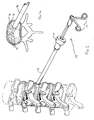
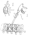
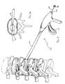
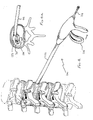
- the instrument of Figure 2 designated generally by reference numeral 20, contains the spinal implant 30 within a distal portion of the elongated tubular member 22. The instrument is inserted through cannula 14.
- the implant delivery device 20 has a pusher 24 that is operatively connected to trigger 26 such that actuation of the trigger 26 moves pusher 24 longitudinally distally to advance the implant 30 from the tubular member 22.
- Figure 2A illustrates the implant 30 partially ejected from device 20;
- Figure 5A illustrates the implant 30 fully deployed and implanted in the disc space. After placement of the implant 30, the delivery device 20 is removed from the body as shown in Figure 5 .
- the implant is C-shaped in configuration as it extends circumferentially along the periphery of the disc space thus providing support along the periphery or circumference of the disc space. It is also contemplated that the implant could be a closed loop, e.g. circular, or extend more than 350 degrees so the end portions overlap. In each of these instances, the implant would be delivered in a substantially straighter configuration and would return to its memorized curved shape upon delivery to the disc space.
- the implant 30 can have a variety of closed and open cross-sectional configurations. Exemplary embodiments of such implants are shown in Figures 7-15 .
- Each of the implants of Figures 7-15 are composed of shape memory material which enables the implant to assume a second substantially straightened configuration as well as a second radially smaller configuration for delivery to the surgical site and return to a memorized first curved configuration and first radially larger (expanded) configuration for positioning at the disc space.
- the memory characteristics of the implant provide sufficient springiness in response to vertebral loads placed on the device by the spine. That is, the implant can move between an unstressed and stressed position in response to a load placed on the implant, but returns to (or toward) its original unstressed position upon release of the load. This provides both support for the vertebral bodies plus the desired flexibility.
- One preferable shape memory material is Nitinol, a nickel titanium alloy, although other shape memory metals or polymeric materials are contemplated.
- the implant 30 can be hollow or alternatively can form a support or outer housing for a filler material.
- the insert (filler) material can fill the void in the implant to provide a more cushioning or a more spring-like effect.
- This "squeezable" insert (filler) can be made of an elastic material such as rubber to provide additional springiness, a viscoelastic material such as menisci and advanced polymers which would compress and more slowly return to its non-compressed state or a porous viscoelastic material such as articular cartilage which will enable exit of fluids through the pores.
- the insert material can also be resorbable.
- the compressed or reduced cross-section condition of the shape memory implant can be achieved by containment within the delivery tube as the inner walls apply stress to the implant.
- cool saline or other fluid can be injected through the tubular portion of the instrument 20 during delivery of the implant to maintain the implant in the cooler softer martensitic state to facilitate ejection.
- the warmer body temperature will transform the implant to the austenitic memorized condition corresponding to an arcuate shape and larger cross-sectional dimension.
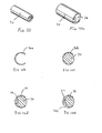
- implant 40 is circular in transverse cross-section and has an overlapping edge 42.
- the diameter of the implant 40 is smaller than the diameter in the unstressed implanted position of Figure 7a .
- the implant 40 can contain a void 41 in the center or optionally include an insert/filler material 44 as described above to fill the interior of implant 40a. Both a hollow and a filled version are illustrated in Figure 7b .
- the filler (insert) material and implant cooperate in a tongue and groove arrangement to enhance retention of the filler material within the implant.
- a groove 45 can be provided in the insert 46 contained within implant 40b to receive tongue 48 or alternatively a groove 47 can be provided in the implant 40c.
- the overlapping portions of the implant 50 are spaced apart, creating a gap 53 by overlapping edge 52.
- the implant (50a), including the gap can be filled with insert material 54 or alternatively be devoid of such material as in implant 50b.
- Figure 8c shows the tongue and groove arrangement, similar to Figure 7c , with the groove 55 for receiving tongue 57 being provided in the insert 56 of implant 50c.
- a groove 58 can alternatively be provided in the implant 50 to receive tongue 59 of insert 51 (see Figs 8a and 8d ).
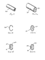
- the implant 60 has a closed loop, i.e. a circular, transverse cross-sectional configuration.
- the implant can be hollow (see implant 60a of Fig. 9b ) or alternatively can be filled with insert material 64 (see implant 60b of Fig. 9c).
- Figure 9d shows the tongue and groove arrangement, similar to Figure 7c , of implant 60d with the groove 65 being provided in the insert 66 to receive tongue 67.
- the groove can be provided in the implant such as groove 68 provided in the implant 60c of Figure 9e .
- implant 70 has an open loop configuration providing a C-shape transverse cross-section.
- the implant can be hollow (see implant 70a of Figure 10b ) or can include an insert material 74 (implant 70b of Figure 10c ). Tongue and groove arrangements are illustrated in the cross-sectional views of Figures 10d and 10e , with Figure 10d reflecting the implant 70 of Figure 10 having groove 75 formed in insert material 76 and Figure 10e showing an alternate embodiment with the tongue 77 on insert material 78 of implant 70c.
- FIG 11 a C-shaped cross-sectional implant 80 according to the present invention is illustrated.
- This implant 80 resembles implant 70 of Figure 10 in that it has an open curved configuration. It differs from the embodiments of Figure 10 , however, in that it is more oval in cross-section.
- insert material 84 can be provided as well as tongue and groove arrangements (85, 87 and 88, 89 in implants 80b and 80c, respectively) as shown in Figures 11d and 11e.
- Figure 11b illustrates implant 80a devoid of filler material.
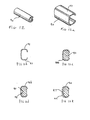
- a C-shaped implant 90 according to the present invention is also illustrated, except that it is more in the form of an open rectangle in cross-section.
- Planar surfaces 91, 92 increase the contact area with the vertebral bodies.
- Insert material 94 can optionally be provided in implant 90a as shown in Figure 12c .
- Alternative tongue and groove arrangements are illustrated in the cross-sectional views of Figure 12d and 12e , with the groove 95 of implant 90b provided on insert material 96 to receive tongue 98 ( Fig. 12d ) and the groove 99 being provided on implant 90c to receive tongue 97 ( Fig. 12e ).
- FIG. 13-15 illustrate alternative embodiments of the implant to increase flexibility during delivery and during compression once inserted.
- implant 100 has a series of fenestrations 102 along its length.
- Narrower slits can alternatively be provided. Although shown extending in an orientation transverse to the disc space (longitudinally aligned with the spine) the fenestrations can alternatively be angled.
- the circumferential slits or openings can be spaced further apart or closer together and can extend for differing degrees around the circumference. When in the memorized curved configuration upon implantation, the slits spread to form wider gaps as shown in the top of view of the implant of Fig. 14 .
- a lattice structure 118 is illustrated in Fig. 15 , also to provide increased flexibility. Filler material can be provided in each of these inserts.
- any of the foregoing implants can be provided with a roughened surface, such as a textured surface, to enhance bone ingrowth to enhance implant retention in the disc space.
- a roughened surface such as a textured surface
- Surface finishes such as hydroxyapatite, calcium silicate and calcium phosphate could also be applied to allow for bone ingrowth.
- the disc nucleus is removed arthroscopically, i.e. through cannula 14, by device 10.
- Cannula 14 can optionally be placed by first inserting a needle and wire, removing the needle and sequentially placing and removing dilators of progressively increasing diameter over the wire until the desired cannula diameter is reached. After removal of the disc, device 10 is withdrawn through cannula 14 and then delivery device 20, containing any of the foregoing implants, is inserted through the cannula.
- the implant is contained within the delivery device 20 in a substantially straightened configuration and in a reduced diameter (compressed/stressed) configuration, either by the walls of the device or by injection of cold saline to transform the implant to the martensitic state as described above.
- FIGs 6 and 6a illustrate the implant 30 positioned within the disc space in an unstressed position ( Fig 6 ) and an example of a stressed position ( Fig 6a ) to illustrate the compressibility of the implant in response to vertebral loads.
- the implant returns to the unstressed position of Figure 6 or at least to a less compressed configuration, depending on the gap between adjacent vertebrae. The degree of compressibility of the implant will depend on the applied load.
- a balloon can be provided as part of the implant delivery system. This is illustrated in Figures 3 and 4 (the cannula is not shown).
- the delivery instrument 120 has an elongated tubular portion 122 and a trigger 126 as in the embodiment of Figure 1 .
- An axial bore 128 is formed along the length of device 120 to receive catheter 132 having an inflatable balloon 134, such as an angioplasty balloon, at the distal end.
- the proximal end 136 of the catheter has an inflation portion for inflating the balloon 134 within the disc space as shown in Figure 3a . This inflation aids to distract the vertebrae to facilitate insertion of the implant.
- trigger 126 is squeezed in the direction of the arrow of Figure 4 to eject the implant contained in the tubular portion 122 as shown in Figure 4a .
- the balloon 134 is deflated and instrument 120 and catheter 132 are withdrawn from the surgical site, leaving the implant in the disc space.
- the balloon catheter can be either an integral part of the delivery instrument or a separate device removably inserted through the bore of the delivery instrument.
Abstract
Description
- This application relates to a spinal implant and more particularly to a spinal disc implant that can be inserted minimally invasively.
- After removal of the intervertebral disc, it has been recognized that the disc space needs to be filled between the adjacent vertebrae. There are two approaches in the prior art to fill the space: one involving placement of a fusion cage and the other involving an artificial disc. Fusion cages are essentially metallic cages packed with bone to promote bone ingrowth. The fusion cages, designed to promote fusion, provide support between the vertebrae, but eliminate motion. Thus, to achieve stability, they sacrifice mobility.
- Artificial disc prostheses of the prior art take many forms. Each form is essentially designed to strike a balance between sufficient stability to support the high loads of the vertebrae and sufficient mobility so as not to curtail movement of the patient. To date, attempts to strike such balance have met with limited success, with the artificial disc providing either stability or mobility, but not both. The need therefore exists for a disc replacement that can better simulate the natural disc by combining adequate support with flexibility.
-
US-B1-6 264 695 discloses a spinal implant according to the preamble of claim 1. - Additionally, in many intervertebral procedures, major open surgery is required. The advantages of endoscopic (minimally invasive) procedures are well known, e.g. smaller incision causing less trauma and reduced infection potential, shorter hospital stays, lower costs, reduced patient recovery time, and reduced pain for the patient. Therefore, it would be advantageous if such an artificial disc, which achieves a beneficial balance between mobility and stability, could be inserted minimally invasively.
- It is therefore an object of the present invention to provide a spinal implant which is capable of being inserted minimally invasively.
- According to the present invention there is provided a spinal implant comprising a material having a first position in the form of a first expanded configuration and a first curved configuration, and a second position in the form of a second configuration having a smaller transverse cross-sectional dimension than in the first expanded configuration, and a second delivery configuration having a more linear configuration than in the first curved configuration, the implant assuming the second position during delivery to the disc space and assuming the first position upon placement within the disc space, the implant being movable once implanted in response to a load placed on the implant by the vertebral bodies, wherein the implant comprises a shape memory material with the first position being a memorized position, and wherein the implant has a C-shaped transverse cross-section in the first expanded configuration, and wherein the second configuration is a radially compressed configuration relative to the first expanded configuration, and wherein the implant is movable towards the second radially compressed configuration in response to the load.
- In an embodiment, the implant is C-shaped in the first curved configuration.
- In an embodiment the implant forms a closed curve in the first curved configuration.
- In an embodiment the implant extends circumferentially along the periphery of the disc space in the first position.
- In an embodiment the implant is substantially rectangular in transverse cross section having at least a first and second substantially planar surface.
- An insert material may be contained within the implant. The implant material made of a variety of materials such as elastic, viscoelastic or porous material. The insert material may fill the void in the implant.
- In an embodiment the insert material is contained within the implant by a tongue and groove arrangement.
- An outer surface of the implant may be roughened to enhance bone ingrowth.
- The implant may include a plurality of openings in an outer surface to enhance flexibility.
- The implant may include a plurality of grooves in an outer surface to enhance flexibility.
- Preferred embodiment(s) of the present disclosure are described herein with reference to the drawings wherein:
-
Fig. 1 is a perspective view of a disc removal device being used in the intra-vertebral space through a cannula (the soft tissues are not shown); -
Fig. 1a is a close up top view of the spinal disc nucleus being removed by the device ofFigure 1 ; -
Fig. 2 is a perspective view of an implant delivery device being used in the intra-vertebral space (the soft tissues are not shown); -
Fig. 2a is a close up top view of a spinal implant of the present invention being delivered from the device ofFigure 2 ; -
Fig. 3 is a perspective view of an alternate embodiment of the delivery device being used in the intra-vertebral space having an integral angioplasty style balloon (the cannula is removed for clarity); -
Fig. 3a is a close up top view of the delivery device ofFigure 3 showing the balloon inflated to distract the vertebral bodies; -
Fig. 4 is a view similar toFigure 3 except showing initial actuation of the handle to deliver the spinal implant; -
Fig. 4a is a close up view showing the balloon inflated to maintain the space between vertebral bodies and the implant being delivered from the device; -
Fig. 5 illustrates the delivery device ofFigure 2 being removed from the spine (the soft tissues are not shown) after implantation of the spinal implant; -
Fig. 5a is a close up top view of the implant ofFigure 2a in place between the vertebral bodies; -
Fig. 6 is a cross-sectional view of the spinal implant ofFigure 2a in its unstressed and unloaded condition between the vertebral bodies (the soft tissues are not shown); -
Fig. 6a is a cross-sectional view of the spinal implant ofFigure 2a in an example of a stressed and loaded condition; - Fig- 7 is a perspective view of one embodiment of an implant that is in a stressed condition (during delivery and when in use);
-
Fig. 7a illustrates the implant ofFigure 7 in an unstressed condition; -
Fig. 7b are cross-sectional views of a filled and unfilled implant of the embodiment ofFig. 7 and Fig. 7a ; -
Fig. 7c are cross sectional views of alternate embodiments of theFig. 7 implant; -
Fig. 8 is a perspective view of another alternate embodiment of an implant that is in a stressed condition (during delivery and when in use); -
Fig. 8a illustrates the implant ofFigure 8 in an unstressed condition; -
Fig. 8b are cross-sectional views of filled and unfilled alternate embodiments of the implant ofFig. 8 ; -
Fig. 8c is a cross sectional view of an alternate embodiment of theFig. 8 implant; -
Fig. 8d is a cross-sectional view of the implant ofFig. 8 ; -
Fig. 9 is a perspective view of another alternate embodiment of an implant that is in a stressed condition (during delivery and when in use); -
Fig. 9a illustrates the implant ofFigure 9 in an unstressed condition; -
Fig. 9b is a cross-sectional view of an unfilled alternate embodiment of the implant ofFig. 9 ; -
Fig. 9c is a cross-sectional view of a filled alternate embodiment of the implant ofFig. 9 ; -
Fig. 9d is a cross-sectional view of the implant ofFig 9 ; -
Fig. 9e is a cross-sectional view of an alternate embodiment of theFig. 9 implant; -
Fig. 10 is a perspective view of an embodiment of the implant of the present invention that is in a stressed condition (during delivery and when in use); -
Fig. 10a illustrates the implant ofFigure 10 in an unstressed condition; -
Figs. 10b and 10c are cross-sectional views of filled and unfilled implants of alternate embodiments ofFig. 10 ; -
Fig. 10d is a cross-sectional view of the implant ofFig 10 ; -
Fig. 10e is a cross-sectional view of an alternate embodiment of the implant ofFig. 10 ; -
Fig. 11 is a perspective view of another embodiment of the implant of the present invention that is in a stressed condition (during delivery and when in use); -
Fig. 11a illustrates the implant ofFigure 11 in an unstressed condition; -
Fig. 11b is a cross sectional view of an unfilled embodiment of the implant ofFig. 11 ; -
Fig. 11c is a cross-sectional view of the implant ofFig. 11 ; -
Figs. 11d and 11e are cross-sectional views of alternate embodiments of the implant ofFig. 11 ; -
Fig. 12 is a perspective view of yet another alternate embodiment of the implant of the present invention that is in a stressed condition (during delivery and when in use); -
Fig. 12a illustrates the implant ofFigure 12 in an unstressed condition; -
Fig. 12b is a cross-sectional view of the implant ofFig. 12 ; -
Fig. 12c is a cross-sectional view of a filled implant embodiment of the implant ofFig. 12 ; -
Figs. 12d and 12e are cross-sectional views of two alternate embodiments of the implant ofFig. 12 ; -
Fig. 13 is a perspective view of an alternate embodiment of the implant having radial slits to increase flexibility; -
Fig. 14 is a top view of the implant ofFig. 13 in the arcuate memorized configuration; and -
Fig. 15 is a perspective view of another alternate embodiment of the implant having a lattice structure. - Referring now in detail to the drawings where like reference numerals identify similar or like components throughout the several views, several different embodiments of the spinal implant of the present invention are described herein. The spinal implants have differing cross-sectional configurations and can optionally contain an insert material to fill the void in the otherwise hollow implant and to provide more cushioning if desired. Each of these variations is described in detail below.
- The spinal implants of the present invention are designed to be inserted minimally invasively into the disc space, thus enabling a smaller incision to be used in the procedure. This is achieved by the implants being compressible radially to a smaller diameter/height for delivery and being deflectable laterally to a substantially linear configuration. Once ejected from the delivery instrument at the desired site, i.e. the disc space between adjacent vertebrae, the implant returns to a larger diameter/height and to a curved configuration. Implanted in the disc space, the spinal implant is radially compressible in response to vertebral loads placed thereon, but attempts to return to its normal non-compressed (radially larger) configuration, thus providing a spring-like action.
- Turning first to the instrumentation for minimally invasively preparing the disc space and for minimally invasively delivering the spinal implant, and with initial reference to
Figures 1 and 1A , a device used in the intra-vertebral space to remove the spinal disc nucleus in a minimally invasive fashion is illustrated. Thedisc removal device 10 has an elongatedtubular portion 12 which is inserted through anarthroscopic cannula 14 and has a pair of cuttingjaws 16 which are operatively connected to and remotely manipulated, i.e. opened and closed, by proximal handle 18 to cut and remove the disc nucleus. Insertion througharthroscopic cannula 14 enables the disc to be removed minimally invasively rather than through a larger incision during an open more invasive surgical procedure. - As the nucleus is removed endoscopically, i.e. through a cannula forming a small incision, the implant of the present invention that is designed to replace the removed disc is also advantageously inserted minimally invasively. The instrument of
Figure 2 , designated generally byreference numeral 20, contains thespinal implant 30 within a distal portion of theelongated tubular member 22. The instrument is inserted throughcannula 14. - The
implant delivery device 20 has apusher 24 that is operatively connected to trigger 26 such that actuation of thetrigger 26 moves pusher 24 longitudinally distally to advance theimplant 30 from thetubular member 22.Figure 2A illustrates theimplant 30 partially ejected fromdevice 20;Figure 5A illustrates theimplant 30 fully deployed and implanted in the disc space. After placement of theimplant 30, thedelivery device 20 is removed from the body as shown inFigure 5 . - As can be appreciated in the plan view of
Figure 5a and the cross-sectional views ofFigure 6 and 6a , the implant is C-shaped in configuration as it extends circumferentially along the periphery of the disc space thus providing support along the periphery or circumference of the disc space. It is also contemplated that the implant could be a closed loop, e.g. circular, or extend more than 350 degrees so the end portions overlap. In each of these instances, the implant would be delivered in a substantially straighter configuration and would return to its memorized curved shape upon delivery to the disc space. - The
implant 30 can have a variety of closed and open cross-sectional configurations. Exemplary embodiments of such implants are shown inFigures 7-15 . Each of the implants ofFigures 7-15 are composed of shape memory material which enables the implant to assume a second substantially straightened configuration as well as a second radially smaller configuration for delivery to the surgical site and return to a memorized first curved configuration and first radially larger (expanded) configuration for positioning at the disc space. Once delivered to the disc space, the memory characteristics of the implant provide sufficient springiness in response to vertebral loads placed on the device by the spine. That is, the implant can move between an unstressed and stressed position in response to a load placed on the implant, but returns to (or toward) its original unstressed position upon release of the load. This provides both support for the vertebral bodies plus the desired flexibility. One preferable shape memory material is Nitinol, a nickel titanium alloy, although other shape memory metals or polymeric materials are contemplated. - It should be appreciated that the alternate embodiments of
Figures 7-15 which show different configurations of the implant illustrate the implant in a linear configuration for simplicity, it being understood that the implant would be formed into a memorized open or closed curve configuration. The length of the implant could also be longer than that shown in the drawings for assuming the curved shape. - The
implant 30 can be hollow or alternatively can form a support or outer housing for a filler material. The insert (filler) material can fill the void in the implant to provide a more cushioning or a more spring-like effect. This "squeezable" insert (filler) can be made of an elastic material such as rubber to provide additional springiness, a viscoelastic material such as menisci and advanced polymers which would compress and more slowly return to its non-compressed state or a porous viscoelastic material such as articular cartilage which will enable exit of fluids through the pores. The insert material can also be resorbable. - The compressed or reduced cross-section condition of the shape memory implant can be achieved by containment within the delivery tube as the inner walls apply stress to the implant. Alternatively, cool saline or other fluid can be injected through the tubular portion of the
instrument 20 during delivery of the implant to maintain the implant in the cooler softer martensitic state to facilitate ejection. Once the implant is advanced from thedelivery instrument 20, the warmer body temperature will transform the implant to the austenitic memorized condition corresponding to an arcuate shape and larger cross-sectional dimension. - Turning first to the embodiment of
Figure 7 , implant 40 is circular in transverse cross-section and has an overlappingedge 42. In the delivery position ofFigure 7 , the diameter of the implant 40 is smaller than the diameter in the unstressed implanted position ofFigure 7a . The implant 40 can contain a void 41 in the center or optionally include an insert/filler material 44 as described above to fill the interior of implant 40a. Both a hollow and a filled version are illustrated inFigure 7b . In the embodiments ofFigure 7c , the filler (insert) material and implant cooperate in a tongue and groove arrangement to enhance retention of the filler material within the implant. Agroove 45 can be provided in theinsert 46 contained within implant 40b to receive tongue 48 or alternatively a groove 47 can be provided in the implant 40c. - In the alternate embodiment of
Figure 8 , the overlapping portions of theimplant 50 are spaced apart, creating agap 53 by overlappingedge 52. The implant (50a), including the gap can be filled withinsert material 54 or alternatively be devoid of such material as in implant 50b.Figure 8c shows the tongue and groove arrangement, similar toFigure 7c , with the groove 55 for receiving tongue 57 being provided in theinsert 56 ofimplant 50c. Agroove 58 can alternatively be provided in theimplant 50 to receivetongue 59 of insert 51 (seeFigs 8a and 8d ). - In the alternate embodiment of
Figure 9 , theimplant 60 has a closed loop, i.e. a circular, transverse cross-sectional configuration. The implant can be hollow (see implant 60a ofFig. 9b ) or alternatively can be filled with insert material 64 (see implant 60b ofFig. 9c). Figure 9d shows the tongue and groove arrangement, similar toFigure 7c , of implant 60d with thegroove 65 being provided in theinsert 66 to receivetongue 67. Alternatively, the groove can be provided in the implant such as groove 68 provided in the implant 60c ofFigure 9e . - In
Figure 10 ,implant 70 according to the present invention has an open loop configuration providing a C-shape transverse cross-section. The implant can be hollow (see implant 70a ofFigure 10b ) or can include an insert material 74 (implant 70b ofFigure 10c ). Tongue and groove arrangements are illustrated in the cross-sectional views ofFigures 10d and 10e , withFigure 10d reflecting theimplant 70 ofFigure 10 havinggroove 75 formed ininsert material 76 andFigure 10e showing an alternate embodiment with thetongue 77 oninsert material 78 of implant 70c. - In
Figure 11 , a C-shapedcross-sectional implant 80 according to the present invention is illustrated. Thisimplant 80 resemblesimplant 70 ofFigure 10 in that it has an open curved configuration. It differs from the embodiments ofFigure 10 , however, in that it is more oval in cross-section. As with the previous embodiments, insertmaterial 84 can be provided as well as tongue and groove arrangements (85, 87 and 88, 89 in implants 80b and 80c, respectively) as shown inFigures 11d and 11e. Figure 11b illustrates implant 80a devoid of filler material. - In the embodiment of
Figure 12 , a C-shapedimplant 90 according to the present invention is also illustrated, except that it is more in the form of an open rectangle in cross-section. Planar surfaces 91, 92 increase the contact area with the vertebral bodies. Insert material 94 can optionally be provided inimplant 90a as shown inFigure 12c . Alternative tongue and groove arrangements are illustrated in the cross-sectional views ofFigure 12d and 12e , with thegroove 95 of implant 90b provided on insert material 96 to receive tongue 98 (Fig. 12d ) and thegroove 99 being provided on implant 90c to receive tongue 97 (Fig. 12e ). -
Figures 13-15 illustrate alternative embodiments of the implant to increase flexibility during delivery and during compression once inserted. InFig. 13 ,implant 100 has a series offenestrations 102 along its length. Narrower slits can alternatively be provided. Although shown extending in an orientation transverse to the disc space (longitudinally aligned with the spine) the fenestrations can alternatively be angled. The circumferential slits or openings can be spaced further apart or closer together and can extend for differing degrees around the circumference. When in the memorized curved configuration upon implantation, the slits spread to form wider gaps as shown in the top of view of the implant ofFig. 14 . A lattice structure 118 is illustrated inFig. 15 , also to provide increased flexibility. Filler material can be provided in each of these inserts. - Any of the foregoing implants can be provided with a roughened surface, such as a textured surface, to enhance bone ingrowth to enhance implant retention in the disc space. Surface finishes such as hydroxyapatite, calcium silicate and calcium phosphate could also be applied to allow for bone ingrowth.
- In use, the disc nucleus is removed arthroscopically, i.e. through
cannula 14, bydevice 10.Cannula 14 can optionally be placed by first inserting a needle and wire, removing the needle and sequentially placing and removing dilators of progressively increasing diameter over the wire until the desired cannula diameter is reached. After removal of the disc,device 10 is withdrawn throughcannula 14 and thendelivery device 20, containing any of the foregoing implants, is inserted through the cannula. The implant is contained within thedelivery device 20 in a substantially straightened configuration and in a reduced diameter (compressed/stressed) configuration, either by the walls of the device or by injection of cold saline to transform the implant to the martensitic state as described above. The implant is then ejected from thetubular member 22 of thedelivery device 20 and implanted in the disc space between the vertebral bodies. Thedelivery instrument 20 andcannula 14 are withdrawn from the body.Figures 6 and 6a illustrate theimplant 30 positioned within the disc space in an unstressed position (Fig 6 ) and an example of a stressed position (Fig 6a ) to illustrate the compressibility of the implant in response to vertebral loads. When the load is released, the implant returns to the unstressed position ofFigure 6 or at least to a less compressed configuration, depending on the gap between adjacent vertebrae. The degree of compressibility of the implant will depend on the applied load. - To facilitate insertion and enhance distraction of the disc space, a balloon can be provided as part of the implant delivery system. This is illustrated in
Figures 3 and4 (the cannula is not shown). Thedelivery instrument 120 has an elongatedtubular portion 122 and atrigger 126 as in the embodiment ofFigure 1 . Anaxial bore 128 is formed along the length ofdevice 120 to receivecatheter 132 having aninflatable balloon 134, such as an angioplasty balloon, at the distal end. The proximal end 136 of the catheter has an inflation portion for inflating theballoon 134 within the disc space as shown inFigure 3a . This inflation aids to distract the vertebrae to facilitate insertion of the implant. After inflation, trigger 126 is squeezed in the direction of the arrow ofFigure 4 to eject the implant contained in thetubular portion 122 as shown inFigure 4a . After implantation, theballoon 134 is deflated andinstrument 120 andcatheter 132 are withdrawn from the surgical site, leaving the implant in the disc space. It should be appreciated that the balloon catheter can be either an integral part of the delivery instrument or a separate device removably inserted through the bore of the delivery instrument.
Claims (11)
- A spinal implant (70, 70a-c; 80, 80a-c; 90, 90a-c; 100; 114) comprising a material having a first position in the form of a first expanded configuration and a first curved configuration, and a second position in the form of a second configuration having a smaller transverse cross-sectional dimension than in the first expanded configuration, and a second delivery configuration having a more linear configuration than in the first curved configuration, the implant assuming the second position during delivery to the disc space and assuming the first position upon placement within the disc space, the implant being movable once implanted in response to a load placed on the implant by the vertebral bodies, characterized in that the implant comprises a shape memory material with the first position being a memorized position, and in that the implant has a C-shaped transverse cross-section in the first expanded configuration, and in that the second configuration is a radially compressed configuration relative to the first expanded configuration, and in that the implant is movable towards the second radially compressed configuration in response to the load.
- A spinal implant as claimed in claim 1, characterized in that the implant (70, 70a-c; 80, 80a-c; 90, 90a-c) is substantially C-shaped in the first curved configuration.
- A spinal implant as claimed in any preceding claim, characterized in that the implant (60, 60a-d) forms a closed curve in the first curved configuration.
- A spinal implant as claimed in any preceding claim, characterized in that the implant extends circumferentially along the periphery of the disc space in the first position.
- A spinal implant as claimed in any preceding claim, characterized in that the implant (90, 90a-c) is substantially rectangular in transverse cross section having at least a first and second substantially planar surface (91, 92).
- A spinal implant as claimed in any preceding claim, characterized in that an insert material (74, 76, 78; 84; 94, 96) is contained within the implant (70, 70b, 70c; 80, 80b, 80c; 90a-c).
- A spinal implant as claimed in claim 6, characterized in that the insert material (74, 76, 78; 84; 94, 96) fills the void in the implant (70, 70b, 70c; 80, 80b, 80c; 90a-c).
- A spinal implant as claimed in claim 6 or 7, characterized in that the insert material (76, 78; 84; 96) is contained within the implant (70, 70c; 80b, 80c; 90b, 90c) by a tongue and groove arrangement (75, 77; 85, 87, 88, 89; 95, 97, 98, 99).
- A spinal implant as claimed in any preceding claim, characterized in that an outer surface of the implant (70, 70a-c; 80, 80a-c; 90, 90a-c; 100; 114) is roughened to enhance bone ingrowth.
- A spinal implant as claimed in any preceding claim, characterized in that the implant (100; 118) includes a plurality of openings in an outer surface to enhance flexibility.
- A spinal implant as claimed in any preceding claim, characterized in that the implant (100) includes a plurality of grooves (102) in an outer surface to enhance flexibility.
Applications Claiming Priority (3)
| Application Number | Priority Date | Filing Date | Title |
|---|---|---|---|
| US32643801P | 2001-10-02 | 2001-10-02 | |
| US326438P | 2001-10-02 | ||
| PCT/US2002/030263 WO2003028587A2 (en) | 2001-10-02 | 2002-09-24 | Spinal implant and method of use |
Publications (2)
| Publication Number | Publication Date |
|---|---|
| EP1432371A2 EP1432371A2 (en) | 2004-06-30 |
| EP1432371B1 true EP1432371B1 (en) | 2009-07-08 |
Family
ID=23272204
Family Applications (1)
| Application Number | Title | Priority Date | Filing Date |
|---|---|---|---|
| EP02800351A Expired - Fee Related EP1432371B1 (en) | 2001-10-02 | 2002-09-24 | Spinal implant |
Country Status (8)
| Country | Link |
|---|---|
| US (2) | US7267687B2 (en) |
| EP (1) | EP1432371B1 (en) |
| JP (1) | JP4394441B2 (en) |
| AU (1) | AU2002334655B2 (en) |
| CA (1) | CA2460766C (en) |
| DE (1) | DE60232893D1 (en) |
| ES (1) | ES2329665T3 (en) |
| WO (1) | WO2003028587A2 (en) |
Families Citing this family (130)
| Publication number | Priority date | Publication date | Assignee | Title |
|---|---|---|---|---|
| US7204851B2 (en) | 2000-08-30 | 2007-04-17 | Sdgi Holdings, Inc. | Method and apparatus for delivering an intervertebral disc implant |
| US7503936B2 (en) | 2000-08-30 | 2009-03-17 | Warsaw Orthopedic, Inc. | Methods for forming and retaining intervertebral disc implants |
| US20050240201A1 (en) * | 2001-02-13 | 2005-10-27 | Yeung Jeffrey E | Disc shunt delivery devices |
| US7291171B2 (en) * | 2002-05-10 | 2007-11-06 | Ferree Bret A | Artificial disc replacement (ADR) using elastic tether member |
| US6793678B2 (en) | 2002-06-27 | 2004-09-21 | Depuy Acromed, Inc. | Prosthetic intervertebral motion disc having dampening |
| US7004971B2 (en) * | 2002-12-31 | 2006-02-28 | Depuy Acromed, Inc. | Annular nucleus pulposus replacement |
| AU2004212942A1 (en) | 2003-02-14 | 2004-09-02 | Depuy Spine, Inc. | In-situ formed intervertebral fusion device |
| US7771478B2 (en) | 2003-04-04 | 2010-08-10 | Theken Spine, Llc | Artificial disc prosthesis |
| EP1633290B9 (en) * | 2003-06-02 | 2009-09-02 | Warsaw Orthopedic, Inc. | Intervertebral disc implants and methods for manufacturing same |
| US20040267367A1 (en) | 2003-06-30 | 2004-12-30 | Depuy Acromed, Inc | Intervertebral implant with conformable endplate |
| ATE515245T1 (en) | 2003-12-11 | 2011-07-15 | Isto Technologies Inc | PARTICLE CARTILAGE SYSTEM |
| US20050229433A1 (en) * | 2004-03-03 | 2005-10-20 | Cachia Victor V | Catheter deliverable foot implant and method of delivering the same |
| US20050222683A1 (en) * | 2004-03-31 | 2005-10-06 | Sdgi Holdings | Shape memory alloy disc replacement device |
| US20050244499A1 (en) * | 2004-05-03 | 2005-11-03 | Robert Diaz | Method and device for reducing susceptibility to fractures in long bones |
| US20050244451A1 (en) * | 2004-05-03 | 2005-11-03 | Robert Diaz | Method and device for reducing susceptibility to fractures in vertebral bodies |
| US7887587B2 (en) * | 2004-06-04 | 2011-02-15 | Synthes Usa, Llc | Soft tissue spacer |
| US7351261B2 (en) * | 2004-06-30 | 2008-04-01 | Depuy Spine, Inc. | Multi-joint implant |
| US20060122704A1 (en) * | 2004-07-27 | 2006-06-08 | Synthes Inc. | Supplementation or replacement of a nucleus pulposus of an intervertebral disc |
| US20060036241A1 (en) | 2004-08-11 | 2006-02-16 | Tzony Siegal | Spinal surgery system and method |
| US8236029B2 (en) | 2004-08-11 | 2012-08-07 | Nlt Spine Ltd. | Devices for introduction into a body via a substantially straight conduit to for a predefined curved configuration, and methods employing such devices |
| WO2006016371A2 (en) * | 2004-08-13 | 2006-02-16 | Mazor Surgical Technologies Ltd | Minimally invasive spinal fusion |
| US20060047296A1 (en) * | 2004-08-31 | 2006-03-02 | Sdg Holdings, Inc. | Annulus replacement system and technique |
| WO2006034436A2 (en) | 2004-09-21 | 2006-03-30 | Stout Medical Group, L.P. | Expandable support device and method of use |
| WO2006068682A1 (en) * | 2004-09-24 | 2006-06-29 | Stout Medical Group, L.P. | Expandable support device and method of use |
| US20060089719A1 (en) * | 2004-10-21 | 2006-04-27 | Trieu Hai H | In situ formation of intervertebral disc implants |
| US20060089642A1 (en) * | 2004-10-27 | 2006-04-27 | Diaz Robert L | Prefracture spinal implant for osteoporotic unfractured bone |
| US20060241758A1 (en) * | 2005-04-20 | 2006-10-26 | Sdgi Holdings, Inc. | Facet spacers |
| US20060247781A1 (en) * | 2005-04-29 | 2006-11-02 | Sdgi Holdings, Inc. | Implant |
| US8702718B2 (en) | 2005-04-29 | 2014-04-22 | Jmea Corporation | Implantation system for tissue repair |
| US7632313B2 (en) | 2005-04-29 | 2009-12-15 | Jmea Corporation | Disc repair system |
| US20060247655A1 (en) * | 2005-05-02 | 2006-11-02 | Sdgi Holdings, Inc. | Instrument to insert a prosthetic implant |
| US20070050034A1 (en) * | 2005-05-24 | 2007-03-01 | Schwardt Jeffrey D | Low-compliance expandable medical device |
| US7601172B2 (en) | 2005-06-15 | 2009-10-13 | Ouroboros Medical, Inc. | Mechanical apparatus and method for artificial disc replacement |
| US8021426B2 (en) * | 2005-06-15 | 2011-09-20 | Ouroboros Medical, Inc. | Mechanical apparatus and method for artificial disc replacement |
| US20070162135A1 (en) * | 2005-06-15 | 2007-07-12 | Jerome Segal | Mechanical apparatus and method for artificial disc replacement |
| US7547319B2 (en) * | 2005-06-15 | 2009-06-16 | Ouroboros Medical | Mechanical apparatus and method for artificial disc replacement |
| US7442210B2 (en) | 2005-06-15 | 2008-10-28 | Jerome Segal | Mechanical apparatus and method for artificial disc replacement |
| US20070010889A1 (en) * | 2005-07-06 | 2007-01-11 | Sdgi Holdings, Inc. | Foldable nucleus replacement device |
| JP5081822B2 (en) | 2005-07-14 | 2012-11-28 | スタウト メディカル グループ,エル.ピー. | Expandable support device and system |
| US7670375B2 (en) | 2005-08-16 | 2010-03-02 | Benvenue Medical, Inc. | Methods for limiting the movement of material introduced between layers of spinal tissue |
| US8366773B2 (en) | 2005-08-16 | 2013-02-05 | Benvenue Medical, Inc. | Apparatus and method for treating bone |
| GB0521582D0 (en) | 2005-10-22 | 2005-11-30 | Depuy Int Ltd | An implant for supporting a spinal column |
| US20070162132A1 (en) | 2005-12-23 | 2007-07-12 | Dominique Messerli | Flexible elongated chain implant and method of supporting body tissue with same |
| GB0600662D0 (en) | 2006-01-13 | 2006-02-22 | Depuy Int Ltd | Spinal support rod kit |
| US8348952B2 (en) * | 2006-01-26 | 2013-01-08 | Depuy International Ltd. | System and method for cooling a spinal correction device comprising a shape memory material for corrective spinal surgery |
| US20070191861A1 (en) * | 2006-01-30 | 2007-08-16 | Sdgi Holdings, Inc. | Instruments and methods for implanting nucleus replacement material in an intervertebral disc nucleus space |
| WO2007131002A2 (en) | 2006-05-01 | 2007-11-15 | Stout Medical Group, L.P. | Expandable support device and method of use |
| US8506636B2 (en) | 2006-09-08 | 2013-08-13 | Theken Spine, Llc | Offset radius lordosis |
| US8900306B2 (en) * | 2006-09-26 | 2014-12-02 | DePuy Synthes Products, LLC | Nucleus anti-expulsion devices and methods |
| US8066750B2 (en) | 2006-10-06 | 2011-11-29 | Warsaw Orthopedic, Inc | Port structures for non-rigid bone plates |
| US8142507B2 (en) * | 2006-11-16 | 2012-03-27 | Rex Medical, L.P. | Spinal implant and method of use |
| US8105382B2 (en) | 2006-12-07 | 2012-01-31 | Interventional Spine, Inc. | Intervertebral implant |
| CA2678006C (en) | 2007-02-21 | 2014-10-14 | Benvenue Medical, Inc. | Devices for treating the spine |
| EP2124777A4 (en) | 2007-02-21 | 2013-06-05 | Benvenue Medical Inc | Devices for treating the spine |
| WO2008109695A2 (en) * | 2007-03-06 | 2008-09-12 | Orthobond, Inc. | Preparation tools and methods of using the same |
| WO2008124737A2 (en) * | 2007-04-10 | 2008-10-16 | Mdesign International | Percutaneous delivery and retrieval systems for shape-changing orthopedic joint devices |
| CA2684040C (en) | 2007-04-12 | 2016-12-06 | Isto Technologies, Inc. | Method of forming an implant using a mold that mimics the shape of the tissue defect site and implant formed therefrom |
| FR2917287B1 (en) * | 2007-06-15 | 2010-09-03 | Ldr Medical | INTERVERTEBRAL PROSTHESIS |
| US8900307B2 (en) | 2007-06-26 | 2014-12-02 | DePuy Synthes Products, LLC | Highly lordosed fusion cage |
| US20090088789A1 (en) * | 2007-09-28 | 2009-04-02 | O'neil Michael J | Balloon With Shape Control For Spinal Procedures |
| GB0720762D0 (en) | 2007-10-24 | 2007-12-05 | Depuy Spine Sorl | Assembly for orthopaedic surgery |
| EP2471493A1 (en) | 2008-01-17 | 2012-07-04 | Synthes GmbH | An expandable intervertebral implant and associated method of manufacturing the same |
| WO2009111480A2 (en) * | 2008-03-03 | 2009-09-11 | Trinity Orthopedics, Llc | Spool intervertebral distraction device and method |
| BRPI0910325A8 (en) | 2008-04-05 | 2019-01-29 | Synthes Gmbh | expandable intervertebral implant |
| WO2010030933A1 (en) * | 2008-09-12 | 2010-03-18 | Articulinx, Inc. | Tether-based orthopedic joint device delivery methods |
| US20100100185A1 (en) * | 2008-10-22 | 2010-04-22 | Warsaw Orthopedic, Inc. | Intervertebral Disc Prosthesis Having Viscoelastic Properties |
| WO2010056895A1 (en) | 2008-11-12 | 2010-05-20 | Stout Medical Group, L.P. | Fixation device and method |
| US20100211176A1 (en) | 2008-11-12 | 2010-08-19 | Stout Medical Group, L.P. | Fixation device and method |
| US10045860B2 (en) | 2008-12-19 | 2018-08-14 | Amicus Design Group, Llc | Interbody vertebral prosthetic device with self-deploying screws |
| US8535327B2 (en) | 2009-03-17 | 2013-09-17 | Benvenue Medical, Inc. | Delivery apparatus for use with implantable medical devices |
| US9526620B2 (en) | 2009-03-30 | 2016-12-27 | DePuy Synthes Products, Inc. | Zero profile spinal fusion cage |
| US8636803B2 (en) | 2009-04-07 | 2014-01-28 | Spinal Stabilization Technologies, Llc | Percutaneous implantable nuclear prosthesis |
| EP2475334A4 (en) | 2009-09-11 | 2014-10-22 | Articulinx Inc | Disc-shaped orthopedic devices |
| US8211126B2 (en) | 2009-09-22 | 2012-07-03 | Jmea Corporation | Tissue repair system |
| WO2011041644A2 (en) * | 2009-10-02 | 2011-04-07 | Paul Andrew Glazer | Devices for delivering spinal disc implants |
| US9168138B2 (en) | 2009-12-09 | 2015-10-27 | DePuy Synthes Products, Inc. | Aspirating implants and method of bony regeneration |
| US9393129B2 (en) | 2009-12-10 | 2016-07-19 | DePuy Synthes Products, Inc. | Bellows-like expandable interbody fusion cage |
| US20110184520A1 (en) * | 2010-01-27 | 2011-07-28 | Warsaw Orthopedic, Inc. | Sacro-iliac joint implant, method and apparatus |
| US8535380B2 (en) | 2010-05-13 | 2013-09-17 | Stout Medical Group, L.P. | Fixation device and method |
| US8979860B2 (en) | 2010-06-24 | 2015-03-17 | DePuy Synthes Products. LLC | Enhanced cage insertion device |
| US9282979B2 (en) | 2010-06-24 | 2016-03-15 | DePuy Synthes Products, Inc. | Instruments and methods for non-parallel disc space preparation |
| EP2588034B1 (en) | 2010-06-29 | 2018-01-03 | Synthes GmbH | Distractible intervertebral implant |
| EP2608747A4 (en) | 2010-08-24 | 2015-02-11 | Flexmedex Llc | Support device and method for use |
| US9402732B2 (en) | 2010-10-11 | 2016-08-02 | DePuy Synthes Products, Inc. | Expandable interspinous process spacer implant |
| US8951288B2 (en) | 2010-11-09 | 2015-02-10 | Benvenue Medical, Inc. | Devices and methods for treatment of a bone fracture |
| US9149286B1 (en) | 2010-11-12 | 2015-10-06 | Flexmedex, LLC | Guidance tool and method for use |
| US8512408B2 (en) | 2010-12-17 | 2013-08-20 | Warsaw Orthopedic, Inc. | Flexiable spinal implant |
| US8814873B2 (en) | 2011-06-24 | 2014-08-26 | Benvenue Medical, Inc. | Devices and methods for treating bone tissue |
| US20130018467A1 (en) * | 2011-07-15 | 2013-01-17 | Sean Suh | Systems and Methods For Vertebral Body and Disc Height Restoration |
| EP2747682A4 (en) | 2011-08-23 | 2015-01-21 | Flexmedex Llc | Tissue removal device and method |
| JP6030140B2 (en) * | 2011-09-20 | 2016-11-24 | ザ・ユニバーシティ・オブ・トレド | Expandable intervertebral cage and mounting method thereof |
| WO2013141990A1 (en) | 2012-03-19 | 2013-09-26 | Amicus Design Group, Llc | Interbody vertebral prosthetic and orthopedic fusion device with self-deploying anchors |
| US9566165B2 (en) | 2012-03-19 | 2017-02-14 | Amicus Design Group, Llc | Interbody vertebral prosthetic and orthopedic fusion device with self-deploying anchors |
| WO2013179102A1 (en) | 2012-05-29 | 2013-12-05 | NLT-Spine Ltd. | Laterally deflectable implant |
| US9532881B2 (en) | 2012-08-12 | 2017-01-03 | Brian Albert Hauck | Memory material implant system and methods of use |
| US20140178343A1 (en) | 2012-12-21 | 2014-06-26 | Jian Q. Yao | Supports and methods for promoting integration of cartilage tissue explants |
| WO2014105972A1 (en) | 2012-12-26 | 2014-07-03 | Koss Scott A | Apparatus, kit, and method for percutaneous intervertebral disc restoration |
| US9522070B2 (en) | 2013-03-07 | 2016-12-20 | Interventional Spine, Inc. | Intervertebral implant |
| US9358120B2 (en) * | 2013-03-14 | 2016-06-07 | DePuy Synthes Products, Inc. | Expandable coil spinal implant |
| US9585761B2 (en) | 2013-03-14 | 2017-03-07 | DePuy Synthes Products, Inc. | Angulated rings and bonded foils for use with balloons for fusion and dynamic stabilization |
| US9480574B2 (en) | 2013-03-14 | 2016-11-01 | Benvenue Medical, Inc. | Spinal fusion implants and devices and methods for deploying such implants |
| US10085783B2 (en) | 2013-03-14 | 2018-10-02 | Izi Medical Products, Llc | Devices and methods for treating bone tissue |
| US9572676B2 (en) | 2013-03-14 | 2017-02-21 | DePuy Synthes Products, Inc. | Adjustable multi-volume balloon for spinal interventions |
| US20140277467A1 (en) | 2013-03-14 | 2014-09-18 | Spinal Stabilization Technologies, Llc | Prosthetic Spinal Disk Nucleus |
| US9295479B2 (en) | 2013-03-14 | 2016-03-29 | Spinal Stabilization Technologies, Llc | Surgical device |
| US9456817B2 (en) | 2014-04-08 | 2016-10-04 | DePuy Synthes Products, Inc. | Methods and devices for spinal correction |
| US10314605B2 (en) | 2014-07-08 | 2019-06-11 | Benvenue Medical, Inc. | Apparatus and methods for disrupting intervertebral disc tissue |
| WO2016073587A1 (en) | 2014-11-04 | 2016-05-12 | Spinal Stabilization Technologies Llc | Percutaneous implantable nuclear prosthesis |
| CA2966748C (en) | 2014-11-04 | 2023-03-21 | Spinal Stabilization Technologies Llc | Percutaneous implantable nuclear prosthesis |
| US9592132B2 (en) | 2015-01-09 | 2017-03-14 | Shape Memory Orthopedics | Shape-memory spinal fusion system |
| CN107405201B (en) | 2015-01-09 | 2020-10-27 | 孚美公司 | Rigid segmented flexible anchor |
| US10022243B2 (en) | 2015-02-06 | 2018-07-17 | Benvenue Medical, Inc. | Graft material injector system and method |
| US11426290B2 (en) | 2015-03-06 | 2022-08-30 | DePuy Synthes Products, Inc. | Expandable intervertebral implant, system, kit and method |
| US10449055B2 (en) | 2015-04-23 | 2019-10-22 | Disc Fix L.L.C. | Systems and methods for treatment of intervertebral disc derangements |
| PL3344156T3 (en) | 2015-09-01 | 2020-07-27 | Spinal Stabilization Technologies Llc | Implantable nuclear prosthesis |
| US11510788B2 (en) | 2016-06-28 | 2022-11-29 | Eit Emerging Implant Technologies Gmbh | Expandable, angularly adjustable intervertebral cages |
| US11596522B2 (en) | 2016-06-28 | 2023-03-07 | Eit Emerging Implant Technologies Gmbh | Expandable and angularly adjustable intervertebral cages with articulating joint |
| US10888433B2 (en) | 2016-12-14 | 2021-01-12 | DePuy Synthes Products, Inc. | Intervertebral implant inserter and related methods |
| US10758286B2 (en) | 2017-03-22 | 2020-09-01 | Benvenue Medical, Inc. | Minimal impact access system to disc space |
| US10398563B2 (en) | 2017-05-08 | 2019-09-03 | Medos International Sarl | Expandable cage |
| US11344424B2 (en) | 2017-06-14 | 2022-05-31 | Medos International Sarl | Expandable intervertebral implant and related methods |
| US10940016B2 (en) | 2017-07-05 | 2021-03-09 | Medos International Sarl | Expandable intervertebral fusion cage |
| WO2019139618A1 (en) | 2018-01-12 | 2019-07-18 | Symbiomedik, Llc | Spinal disc implant and device and method for percutaneous delivery of the spinal disc implant |
| US11583327B2 (en) | 2018-01-29 | 2023-02-21 | Spinal Elements, Inc. | Minimally invasive interbody fusion |
| WO2019178575A1 (en) | 2018-03-16 | 2019-09-19 | Benvenue Medical, Inc. | Articulated instrumentation and methods of using the same |
| CA3111639A1 (en) | 2018-09-04 | 2020-05-28 | Spinal Stabilization Technologies, Llc | Implantable nuclear prosthesis, kits, and related methods |
| US11446156B2 (en) | 2018-10-25 | 2022-09-20 | Medos International Sarl | Expandable intervertebral implant, inserter instrument, and related methods |
| US11426286B2 (en) | 2020-03-06 | 2022-08-30 | Eit Emerging Implant Technologies Gmbh | Expandable intervertebral implant |
| US11850160B2 (en) | 2021-03-26 | 2023-12-26 | Medos International Sarl | Expandable lordotic intervertebral fusion cage |
| US11752009B2 (en) | 2021-04-06 | 2023-09-12 | Medos International Sarl | Expandable intervertebral fusion cage |
Family Cites Families (105)
| Publication number | Priority date | Publication date | Assignee | Title |
|---|---|---|---|---|
| US77701A (en) * | 1868-05-05 | William youngblood | ||
| US10021A (en) * | 1853-09-13 | Screw-eastemtito- for boots and shoes | ||
| US93154A (en) * | 1869-07-27 | Improvement | ||
| US77641A (en) * | 1868-05-05 | Improvement in hay-eams and loadees | ||
| US120269A (en) * | 1871-10-24 | Improvement in valves for steamboat engines | ||
| US18390A (en) * | 1857-10-13 | Improvement in harvesters | ||
| US173851A (en) * | 1876-02-22 | Improvement in reapers and mowers | ||
| SE391122B (en) * | 1971-01-25 | 1977-02-07 | Cutter Lab | PROTESTS IN THE FORM OF A SPINE BONIC DISC AND PROCEDURES FOR MANUFACTURE THEREOF |
| GB8718627D0 (en) * | 1987-08-06 | 1987-09-09 | Showell A W Sugicraft Ltd | Spinal implants |
| US6770074B2 (en) | 1988-06-13 | 2004-08-03 | Gary Karlin Michelson | Apparatus for use in inserting spinal implants |
| DE69408792T2 (en) * | 1993-06-11 | 1998-09-24 | Johnson & Johnson Professional | SURGICAL IMPLANT |
| US5567119A (en) * | 1993-10-28 | 1996-10-22 | Sims Deltec, Inc. | Bag/syringe enclosure arrangements and methods |
| EP0700671B1 (en) * | 1994-09-08 | 2001-08-08 | Stryker Technologies Corporation | Hydrogel intervertebral disc nucleus |
| US5824093A (en) | 1994-10-17 | 1998-10-20 | Raymedica, Inc. | Prosthetic spinal disc nucleus |
| US5578074A (en) * | 1994-12-22 | 1996-11-26 | Target Therapeutics, Inc. | Implant delivery method and assembly |
| WO1997031517A2 (en) | 1995-03-27 | 1997-08-28 | Sdgi Holdings, Inc. | Spinal fusion implants and tools for insertion and revision |
| US6149688A (en) * | 1995-06-07 | 2000-11-21 | Surgical Dynamics, Inc. | Artificial bone graft implant |
| US5830222A (en) * | 1995-10-13 | 1998-11-03 | Transvascular, Inc. | Device, system and method for intersititial transvascular intervention |
| KR100392091B1 (en) * | 1995-10-20 | 2004-02-05 | 신테스 아게 츄어 | Intervertebral implant with compressible hollow elements |
| EP0773008B2 (en) * | 1995-11-08 | 2009-05-20 | Zimmer GmbH | Intervertebral prosthesis |
| US5716416A (en) * | 1996-09-10 | 1998-02-10 | Lin; Chih-I | Artificial intervertebral disk and method for implanting the same |
| US5836948A (en) * | 1997-01-02 | 1998-11-17 | Saint Francis Medical Technologies, Llc | Spine distraction implant and method |
| US5749916A (en) * | 1997-01-21 | 1998-05-12 | Spinal Innovations | Fusion implant |
| ES2302349T3 (en) | 1997-03-07 | 2008-07-01 | Disc-O-Tech Medical Technologies, Ltd. | SYSTEMS FOR THE STABILIZATION, FIXING AND REPAIR OSEA AND VERTEBRAL PERCUTANEAS. |
| DE19710392C1 (en) | 1997-03-13 | 1999-07-01 | Haehnel Michael | Slipped disc implant comprises an extensible, hinged or wound body |
| US6306170B2 (en) * | 1997-04-25 | 2001-10-23 | Tegementa, L.L.C. | Threaded fusion cage anchoring device and method |
| US5800549A (en) | 1997-04-30 | 1998-09-01 | Howmedica Inc. | Method and apparatus for injecting an elastic spinal implant |
| US5824094A (en) * | 1997-10-17 | 1998-10-20 | Acromed Corporation | Spinal disc |
| DE29901613U1 (en) * | 1998-01-23 | 1999-04-08 | Aesculap Ag & Co Kg | Intervertebral implant |
| US6224630B1 (en) * | 1998-05-29 | 2001-05-01 | Advanced Bio Surfaces, Inc. | Implantable tissue repair device |
| US6132465A (en) | 1998-06-04 | 2000-10-17 | Raymedica, Inc. | Tapered prosthetic spinal disc nucleus |
| DE19826619A1 (en) * | 1998-06-17 | 1999-12-30 | Ulrich Gmbh & Co Kg | Implant for the fusion of two vertebrae |
| US6136031A (en) * | 1998-06-17 | 2000-10-24 | Surgical Dynamics, Inc. | Artificial intervertebral disc |
| US6296664B1 (en) * | 1998-06-17 | 2001-10-02 | Surgical Dynamics, Inc. | Artificial intervertebral disc |
| US6117174A (en) | 1998-09-16 | 2000-09-12 | Nolan; Wesley A. | Spinal implant device |
| US6193757B1 (en) * | 1998-10-29 | 2001-02-27 | Sdgi Holdings, Inc. | Expandable intervertebral spacers |
| FR2787015B1 (en) * | 1998-12-11 | 2001-04-27 | Dimso Sa | INTERVERTEBRAL DISC PROSTHESIS WITH COMPRESSIBLE BODY |
| US6612091B1 (en) * | 1998-12-16 | 2003-09-02 | Michael Glover | Architectural building panel |
| US6206923B1 (en) | 1999-01-08 | 2001-03-27 | Sdgi Holdings, Inc. | Flexible implant using partially demineralized bone |
| US6245108B1 (en) * | 1999-02-25 | 2001-06-12 | Spineco | Spinal fusion implant |
| EP1253854A4 (en) | 1999-03-07 | 2010-01-06 | Discure Ltd | Method and apparatus for computerized surgery |
| WO2000062684A1 (en) | 1999-04-16 | 2000-10-26 | Nuvasive, Inc. | Systems for securing facet joints together |
| CA2376097A1 (en) | 1999-06-04 | 2000-12-14 | Sdgi Holdings, Inc. | Artificial disc implant |
| US6419705B1 (en) * | 1999-06-23 | 2002-07-16 | Sulzer Spine-Tech Inc. | Expandable fusion device and method |
| NL1012719C1 (en) | 1999-07-28 | 2001-01-30 | Veldhuizen Dr Ag | Spine prosthesis. |
| US6508839B1 (en) * | 1999-08-18 | 2003-01-21 | Intrinsic Orthopedics, Inc. | Devices and methods of vertebral disc augmentation |
| US6425919B1 (en) * | 1999-08-18 | 2002-07-30 | Intrinsic Orthopedics, Inc. | Devices and methods of vertebral disc augmentation |
| US6264695B1 (en) * | 1999-09-30 | 2001-07-24 | Replication Medical, Inc. | Spinal nucleus implant |
| US6432107B1 (en) * | 2000-01-15 | 2002-08-13 | Bret A. Ferree | Enhanced surface area spinal fusion devices |
| US20030153976A1 (en) | 1999-10-20 | 2003-08-14 | Cauthen Joseph C. | Spinal disc annulus reconstruction method and spinal disc annulus stent |
| WO2003011155A2 (en) | 1999-10-20 | 2003-02-13 | Anulex Technologies, Inc. | Spinal disc annulus reconstruction method and spinal disc annulus stent |
| US6592625B2 (en) * | 1999-10-20 | 2003-07-15 | Anulex Technologies, Inc. | Spinal disc annulus reconstruction method and spinal disc annulus stent |
| US6592624B1 (en) * | 1999-11-24 | 2003-07-15 | Depuy Acromed, Inc. | Prosthetic implant element |
| WO2001045577A2 (en) | 1999-12-06 | 2001-06-28 | Sdgi Holdings, Inc. | Intervertebral disc treatment devices and methods |
| US6648915B2 (en) * | 1999-12-23 | 2003-11-18 | John A. Sazy | Intervertebral cage and method of use |
| US6805695B2 (en) | 2000-04-04 | 2004-10-19 | Spinalabs, Llc | Devices and methods for annular repair of intervertebral discs |
| US20020026244A1 (en) | 2000-08-30 | 2002-02-28 | Trieu Hai H. | Intervertebral disc nucleus implants and methods |
| EP1563808B1 (en) * | 2000-08-30 | 2008-04-02 | Warsaw Orthopedic, Inc. | Intervertebral disc nucleus implants |
| AU2002243270B2 (en) | 2000-10-25 | 2006-03-09 | Warsaw Orthopedic, Inc. | Vertically expanding intervertebral body fusion device |
| US6613089B1 (en) * | 2000-10-25 | 2003-09-02 | Sdgi Holdings, Inc. | Laterally expanding intervertebral fusion device |
| US6712853B2 (en) | 2000-12-15 | 2004-03-30 | Spineology, Inc. | Annulus-reinforcing band |
| US6652585B2 (en) | 2001-02-28 | 2003-11-25 | Sdgi Holdings, Inc. | Flexible spine stabilization system |
| WO2003002040A1 (en) | 2001-06-27 | 2003-01-09 | Mathys Medizinaltechnik Ag | Intervertebral disk prosthesis |
| US6607558B2 (en) * | 2001-07-03 | 2003-08-19 | Axiomed Spine Corporation | Artificial disc |
| EP1287795B1 (en) * | 2001-08-24 | 2008-06-18 | Zimmer GmbH | Artificial spinal disc |
| DE50114037D1 (en) * | 2001-08-24 | 2008-07-31 | Zimmer Gmbh | Artificial disc |
| DE10152567A1 (en) | 2001-10-24 | 2003-05-08 | Tutogen Medical Gmbh | implant |
| FR2836373B1 (en) | 2002-02-26 | 2005-03-25 | Materiel Orthopedique En Abreg | CONNECTING INTERSOMATIC IMPLANTS FOR INSERTING BONE GRAFT FOR REALIZING INTERVERTEBRAL FUSION, INSTRUMENTS FOR CONNECTING THESE IMPLANTS |
| US20060106462A1 (en) | 2002-04-16 | 2006-05-18 | Tsou Paul M | Implant material for minimally invasive spinal interbody fusion surgery |
| US7660623B2 (en) | 2003-01-30 | 2010-02-09 | Medtronic Navigation, Inc. | Six degree of freedom alignment display for medical procedures |
| AU2004212942A1 (en) | 2003-02-14 | 2004-09-02 | Depuy Spine, Inc. | In-situ formed intervertebral fusion device |
| US7351262B2 (en) | 2003-06-05 | 2008-04-01 | Warsaw Orthopedic, Inc. | Bone implants and methods of making same |
| DE112004001370B8 (en) | 2003-07-25 | 2010-06-10 | Impliant Ltd. | Elastomeric nucleus replacement |
| FR2861582B1 (en) | 2003-10-29 | 2006-02-10 | Eurosurgical | INTERSOMATIC CAGE FOR LUMBAR FUSION FIRST TRANSFORAMINAL AND CAGE HOLDER DEVICE |
| US7905920B2 (en) | 2004-08-19 | 2011-03-15 | Foster-Miller, Inc. | Support system for intervertebral fusion |
| US7682393B2 (en) | 2004-10-14 | 2010-03-23 | Warsaw Orthopedic, Inc. | Implant system, method, and instrument for augmentation or reconstruction of intervertebral disc |
| US20060089646A1 (en) | 2004-10-26 | 2006-04-27 | Bonutti Peter M | Devices and methods for stabilizing tissue and implants |
| US20060265077A1 (en) | 2005-02-23 | 2006-11-23 | Zwirkoski Paul A | Spinal repair |
| ATE531346T1 (en) | 2005-02-24 | 2011-11-15 | Morphogeny Llc | CONNECTED, SLIDING AND MATCHABLE ROTATABLE COMPONENTS |
| US7267690B2 (en) | 2005-03-09 | 2007-09-11 | Vertebral Technologies, Inc. | Interlocked modular disc nucleus prosthesis |
| US7182783B2 (en) | 2005-04-25 | 2007-02-27 | Sdgi Holdings, Inc. | Selectively expandable composite structures for spinal arthroplasty |
| US20060247781A1 (en) | 2005-04-29 | 2006-11-02 | Sdgi Holdings, Inc. | Implant |
| US20060247776A1 (en) | 2005-05-02 | 2006-11-02 | The Board Of Trustees Of The Leland Stanford Junior University | Systems and methods for augmenting intervertebral discs |
| US7909872B2 (en) | 2005-06-03 | 2011-03-22 | Zipnick Richard I | Minimally invasive apparatus to manipulate and revitalize spinal column disc |
| EP1731116B1 (en) | 2005-06-08 | 2019-08-07 | coLigne AG | Intervertebal implant |
| US7442210B2 (en) | 2005-06-15 | 2008-10-28 | Jerome Segal | Mechanical apparatus and method for artificial disc replacement |
| US8021426B2 (en) | 2005-06-15 | 2011-09-20 | Ouroboros Medical, Inc. | Mechanical apparatus and method for artificial disc replacement |
| US20070010889A1 (en) | 2005-07-06 | 2007-01-11 | Sdgi Holdings, Inc. | Foldable nucleus replacement device |
| US7670375B2 (en) | 2005-08-16 | 2010-03-02 | Benvenue Medical, Inc. | Methods for limiting the movement of material introduced between layers of spinal tissue |
| US8882841B2 (en) | 2005-09-16 | 2014-11-11 | Us Spine, Inc. | Steerable interbody fusion cage |
| US20070150064A1 (en) | 2005-12-22 | 2007-06-28 | Depuy Spine, Inc. | Methods and devices for intervertebral augmentation |
| US20070162132A1 (en) | 2005-12-23 | 2007-07-12 | Dominique Messerli | Flexible elongated chain implant and method of supporting body tissue with same |
| US20070191861A1 (en) | 2006-01-30 | 2007-08-16 | Sdgi Holdings, Inc. | Instruments and methods for implanting nucleus replacement material in an intervertebral disc nucleus space |
| DE202006005868U1 (en) | 2006-04-06 | 2006-06-08 | Aesculap Ag & Co. Kg | Implant replacing intervertebral disk, comprising plates divided into movable segments lifted by expanding elements |
| US8034110B2 (en) | 2006-07-31 | 2011-10-11 | Depuy Spine, Inc. | Spinal fusion implant |
| US20080039942A1 (en) | 2006-08-11 | 2008-02-14 | Bergeron Brian J | Spinal implant |
| US8025697B2 (en) | 2006-09-21 | 2011-09-27 | Custom Spine, Inc. | Articulating interbody spacer, vertebral body replacement |
| US8021429B2 (en) | 2007-03-08 | 2011-09-20 | Zimmer Spine, Inc. | Deployable segmented TLIF device |
| US20080255624A1 (en) | 2007-03-30 | 2008-10-16 | Gregory Arcenio | Methods and devices for multipoint access of a body part |
| CA2720977A1 (en) | 2007-04-09 | 2008-10-16 | Vertiflex, Inc. | Multi-component interbody device |
| FR2917287B1 (en) | 2007-06-15 | 2010-09-03 | Ldr Medical | INTERVERTEBRAL PROSTHESIS |
| US9044333B2 (en) | 2007-07-27 | 2015-06-02 | R Tree Innovations, Llc | Inter-body implantation system and method |
| US7985231B2 (en) | 2007-12-31 | 2011-07-26 | Kyphon Sarl | Bone fusion device and methods |
| US20090254180A1 (en) | 2008-01-14 | 2009-10-08 | Walt Pazanowski | Customizable vertebral replacement assembly system |
| US20090248092A1 (en) | 2008-03-26 | 2009-10-01 | Jonathan Bellas | Posterior Intervertebral Disc Inserter and Expansion Techniques |
-
2002
- 2002-09-24 JP JP2003531927A patent/JP4394441B2/en not_active Expired - Fee Related
- 2002-09-24 CA CA2460766A patent/CA2460766C/en not_active Expired - Fee Related
- 2002-09-24 US US10/253,446 patent/US7267687B2/en not_active Expired - Lifetime
- 2002-09-24 DE DE60232893T patent/DE60232893D1/en not_active Expired - Lifetime
- 2002-09-24 EP EP02800351A patent/EP1432371B1/en not_active Expired - Fee Related
- 2002-09-24 WO PCT/US2002/030263 patent/WO2003028587A2/en active Application Filing
- 2002-09-24 ES ES02800351T patent/ES2329665T3/en not_active Expired - Lifetime
- 2002-09-24 AU AU2002334655A patent/AU2002334655B2/en not_active Ceased
-
2007
- 2007-06-22 US US11/821,300 patent/US9095449B2/en not_active Expired - Fee Related
Also Published As
| Publication number | Publication date |
|---|---|
| US20030199979A1 (en) | 2003-10-23 |
| DE60232893D1 (en) | 2009-08-20 |
| JP4394441B2 (en) | 2010-01-06 |
| EP1432371A2 (en) | 2004-06-30 |
| US9095449B2 (en) | 2015-08-04 |
| JP2005504584A (en) | 2005-02-17 |
| AU2002334655B2 (en) | 2008-06-05 |
| WO2003028587A3 (en) | 2003-08-21 |
| WO2003028587A2 (en) | 2003-04-10 |
| CA2460766A1 (en) | 2003-04-10 |
| US7267687B2 (en) | 2007-09-11 |
| ES2329665T3 (en) | 2009-11-30 |
| CA2460766C (en) | 2010-06-01 |
| US20080009944A1 (en) | 2008-01-10 |
Similar Documents
| Publication | Publication Date | Title |
|---|---|---|
| EP1432371B1 (en) | Spinal implant | |
| AU2002334655A1 (en) | Spinal implant and method of use | |
| US9259324B2 (en) | Spinal implant and method of use | |
| EP1421921B1 (en) | Artificial spinal disc | |
| US7220281B2 (en) | Implant for reinforcing and annulus fibrosis | |
| EP1214026B1 (en) | Device of vertebral disc augmentation | |
| US20090281517A1 (en) | System and method for repairing an intervertebral disc | |
| US20120316648A1 (en) | Intervertebral disc reinforcement systems | |
| AU2009200502B2 (en) | Artifical spinal disc |
Legal Events
| Date | Code | Title | Description |
|---|---|---|---|
| PUAI | Public reference made under article 153(3) epc to a published international application that has entered the european phase |
Free format text: ORIGINAL CODE: 0009012 |
|
| 17P | Request for examination filed |
Effective date: 20040421 |
|
| AK | Designated contracting states |
Kind code of ref document: A2 Designated state(s): AT BE BG CH CY CZ DE DK EE ES FI FR GB GR IE IT LI LU MC NL PT SE SK TR |
|
| 17Q | First examination report despatched |
Effective date: 20080606 |
|
| GRAP | Despatch of communication of intention to grant a patent |
Free format text: ORIGINAL CODE: EPIDOSNIGR1 |
|
| RTI1 | Title (correction) |
Free format text: SPINAL IMPLANT |
|
| GRAS | Grant fee paid |
Free format text: ORIGINAL CODE: EPIDOSNIGR3 |
|
| GRAA | (expected) grant |
Free format text: ORIGINAL CODE: 0009210 |
|
| AK | Designated contracting states |
Kind code of ref document: B1 Designated state(s): DE ES FR GB IT |
|
| REG | Reference to a national code |
Ref country code: GB Ref legal event code: FG4D |
|
| REF | Corresponds to: |
Ref document number: 60232893 Country of ref document: DE Date of ref document: 20090820 Kind code of ref document: P |
|
| REG | Reference to a national code |
Ref country code: ES Ref legal event code: FG2A Ref document number: 2329665 Country of ref document: ES Kind code of ref document: T3 |
|
| PLBE | No opposition filed within time limit |
Free format text: ORIGINAL CODE: 0009261 |
|
| STAA | Information on the status of an ep patent application or granted ep patent |
Free format text: STATUS: NO OPPOSITION FILED WITHIN TIME LIMIT |
|
| 26N | No opposition filed |
Effective date: 20100409 |
|
| PGFP | Annual fee paid to national office [announced via postgrant information from national office to epo] |
Ref country code: ES Payment date: 20130905 Year of fee payment: 12 |
|
| PGFP | Annual fee paid to national office [announced via postgrant information from national office to epo] |
Ref country code: FR Payment date: 20130924 Year of fee payment: 12 Ref country code: GB Payment date: 20130913 Year of fee payment: 12 |
|
| PGFP | Annual fee paid to national office [announced via postgrant information from national office to epo] |
Ref country code: IT Payment date: 20130913 Year of fee payment: 12 |
|
| GBPC | Gb: european patent ceased through non-payment of renewal fee |
Effective date: 20140924 |
|
| REG | Reference to a national code |
Ref country code: FR Ref legal event code: ST Effective date: 20150529 |
|
| PG25 | Lapsed in a contracting state [announced via postgrant information from national office to epo] |
Ref country code: GB Free format text: LAPSE BECAUSE OF NON-PAYMENT OF DUE FEES Effective date: 20140924 |
|
| PG25 | Lapsed in a contracting state [announced via postgrant information from national office to epo] |
Ref country code: FR Free format text: LAPSE BECAUSE OF NON-PAYMENT OF DUE FEES Effective date: 20140930 Ref country code: IT Free format text: LAPSE BECAUSE OF NON-PAYMENT OF DUE FEES Effective date: 20140924 |
|
| REG | Reference to a national code |
Ref country code: ES Ref legal event code: FD2A Effective date: 20160601 |
|
| PG25 | Lapsed in a contracting state [announced via postgrant information from national office to epo] |
Ref country code: ES Free format text: LAPSE BECAUSE OF NON-PAYMENT OF DUE FEES Effective date: 20140925 |
|
| PGFP | Annual fee paid to national office [announced via postgrant information from national office to epo] |
Ref country code: DE Payment date: 20180928 Year of fee payment: 17 |
|
| REG | Reference to a national code |
Ref country code: DE Ref legal event code: R119 Ref document number: 60232893 Country of ref document: DE |
|
| PG25 | Lapsed in a contracting state [announced via postgrant information from national office to epo] |
Ref country code: DE Free format text: LAPSE BECAUSE OF NON-PAYMENT OF DUE FEES Effective date: 20200401 |