EP1432370B1 - Prothese de nucleus intervertebral et son dispositif d'insertion - Google Patents
Prothese de nucleus intervertebral et son dispositif d'insertion Download PDFInfo
- Publication number
- EP1432370B1 EP1432370B1 EP02798760A EP02798760A EP1432370B1 EP 1432370 B1 EP1432370 B1 EP 1432370B1 EP 02798760 A EP02798760 A EP 02798760A EP 02798760 A EP02798760 A EP 02798760A EP 1432370 B1 EP1432370 B1 EP 1432370B1
- Authority
- EP
- European Patent Office
- Prior art keywords
- prosthesis
- female part
- deformable
- male part
- intervertebral
- Prior art date
- Legal status (The legal status is an assumption and is not a legal conclusion. Google has not performed a legal analysis and makes no representation as to the accuracy of the status listed.)
- Expired - Lifetime
Links
Images


Classifications
-
- A—HUMAN NECESSITIES
- A61—MEDICAL OR VETERINARY SCIENCE; HYGIENE
- A61F—FILTERS IMPLANTABLE INTO BLOOD VESSELS; PROSTHESES; DEVICES PROVIDING PATENCY TO, OR PREVENTING COLLAPSING OF, TUBULAR STRUCTURES OF THE BODY, e.g. STENTS; ORTHOPAEDIC, NURSING OR CONTRACEPTIVE DEVICES; FOMENTATION; TREATMENT OR PROTECTION OF EYES OR EARS; BANDAGES, DRESSINGS OR ABSORBENT PADS; FIRST-AID KITS
- A61F2/00—Filters implantable into blood vessels; Prostheses, i.e. artificial substitutes or replacements for parts of the body; Appliances for connecting them with the body; Devices providing patency to, or preventing collapsing of, tubular structures of the body, e.g. stents
- A61F2/02—Prostheses implantable into the body
- A61F2/30—Joints
- A61F2/44—Joints for the spine, e.g. vertebrae, spinal discs
- A61F2/442—Intervertebral or spinal discs, e.g. resilient
-
- A—HUMAN NECESSITIES
- A61—MEDICAL OR VETERINARY SCIENCE; HYGIENE
- A61F—FILTERS IMPLANTABLE INTO BLOOD VESSELS; PROSTHESES; DEVICES PROVIDING PATENCY TO, OR PREVENTING COLLAPSING OF, TUBULAR STRUCTURES OF THE BODY, e.g. STENTS; ORTHOPAEDIC, NURSING OR CONTRACEPTIVE DEVICES; FOMENTATION; TREATMENT OR PROTECTION OF EYES OR EARS; BANDAGES, DRESSINGS OR ABSORBENT PADS; FIRST-AID KITS
- A61F2/00—Filters implantable into blood vessels; Prostheses, i.e. artificial substitutes or replacements for parts of the body; Appliances for connecting them with the body; Devices providing patency to, or preventing collapsing of, tubular structures of the body, e.g. stents
- A61F2/02—Prostheses implantable into the body
- A61F2/30—Joints
- A61F2/44—Joints for the spine, e.g. vertebrae, spinal discs
-
- A—HUMAN NECESSITIES
- A61—MEDICAL OR VETERINARY SCIENCE; HYGIENE
- A61F—FILTERS IMPLANTABLE INTO BLOOD VESSELS; PROSTHESES; DEVICES PROVIDING PATENCY TO, OR PREVENTING COLLAPSING OF, TUBULAR STRUCTURES OF THE BODY, e.g. STENTS; ORTHOPAEDIC, NURSING OR CONTRACEPTIVE DEVICES; FOMENTATION; TREATMENT OR PROTECTION OF EYES OR EARS; BANDAGES, DRESSINGS OR ABSORBENT PADS; FIRST-AID KITS
- A61F2/00—Filters implantable into blood vessels; Prostheses, i.e. artificial substitutes or replacements for parts of the body; Appliances for connecting them with the body; Devices providing patency to, or preventing collapsing of, tubular structures of the body, e.g. stents
- A61F2/02—Prostheses implantable into the body
- A61F2/30—Joints
- A61F2/46—Special tools or methods for implanting or extracting artificial joints, accessories, bone grafts or substitutes, or particular adaptations therefor
- A61F2/4603—Special tools or methods for implanting or extracting artificial joints, accessories, bone grafts or substitutes, or particular adaptations therefor for insertion or extraction of endoprosthetic joints or of accessories thereof
- A61F2/4611—Special tools or methods for implanting or extracting artificial joints, accessories, bone grafts or substitutes, or particular adaptations therefor for insertion or extraction of endoprosthetic joints or of accessories thereof of spinal prostheses
-
- A—HUMAN NECESSITIES
- A61—MEDICAL OR VETERINARY SCIENCE; HYGIENE
- A61F—FILTERS IMPLANTABLE INTO BLOOD VESSELS; PROSTHESES; DEVICES PROVIDING PATENCY TO, OR PREVENTING COLLAPSING OF, TUBULAR STRUCTURES OF THE BODY, e.g. STENTS; ORTHOPAEDIC, NURSING OR CONTRACEPTIVE DEVICES; FOMENTATION; TREATMENT OR PROTECTION OF EYES OR EARS; BANDAGES, DRESSINGS OR ABSORBENT PADS; FIRST-AID KITS
- A61F2/00—Filters implantable into blood vessels; Prostheses, i.e. artificial substitutes or replacements for parts of the body; Appliances for connecting them with the body; Devices providing patency to, or preventing collapsing of, tubular structures of the body, e.g. stents
- A61F2/02—Prostheses implantable into the body
- A61F2/30—Joints
- A61F2/46—Special tools or methods for implanting or extracting artificial joints, accessories, bone grafts or substitutes, or particular adaptations therefor
- A61F2/4603—Special tools or methods for implanting or extracting artificial joints, accessories, bone grafts or substitutes, or particular adaptations therefor for insertion or extraction of endoprosthetic joints or of accessories thereof
- A61F2002/4625—Special tools or methods for implanting or extracting artificial joints, accessories, bone grafts or substitutes, or particular adaptations therefor for insertion or extraction of endoprosthetic joints or of accessories thereof with relative movement between parts of the instrument during use
- A61F2002/4627—Special tools or methods for implanting or extracting artificial joints, accessories, bone grafts or substitutes, or particular adaptations therefor for insertion or extraction of endoprosthetic joints or of accessories thereof with relative movement between parts of the instrument during use with linear motion along or rotating motion about the instrument axis or the implantation direction, e.g. telescopic, along a guiding rod, screwing inside the instrument
Definitions
- the present invention relates to an intervertebral disk prosthesis and its insertion means.
- This prosthesis after insertion and removal of the insertion means replaces the nucleus of the existing cavity after a partial or total ablation of the latter by preserving the annulus of the intervertebral disc concerned.
- intervertebral disk linking two vertebral bodies and which has a complex operation.
- This disk is composed of a centrally located nucleus pulposus and an annulus fibrosus fibrous peripheral structure containing the nucleus and firmly connecting the vertebral endplates.
- the intervertebral disks are subject to degeneration, in particular those of the lumbar spine which are most often solicited.
- a degenerate disk can be treated by replacing all or part of the nucleus and damaged annulus.
- Many invasive systems replace the entire nucleus as well as most of the annulus.
- the patent EP 0919209 describes a nucleus prosthesis formed of a dry hydrogel block which, after implantation, will be loaded with water and swell at least one millimeter in height, the incision of the annulus must in this case be wider in order to be able to to pass the block, its role as a rampart is lessened, the inventors then proposed to put two smaller blocks, each block being entered into each other by a reduced orifice, in this case the blocks have no mechanical connection and there are empty spaces inside the cavity that can not be filled continuously. Concentrations of stress will appear on the annulus already damaged, implicating the life of the implant and the vitality of the annulus.
- the problem can be solved using an elastic envelope, through an orifice made in the annulus that adapts to the cavity by elastic expansion. It is then necessary to inject a viscous filling material which by polymerizing comes to fill the prosthesis and fill the cavity. This operation requires an additional injection phase which, in some cases, can be restrictive because it increases the operating time.
- the patent US 5800 549A is a force generator for injecting a spinal implant, the means used are different from those of the present invention which use extremely simple means based on the material used.
- the patent US 5645 597 A describes a method for removing the nucleus, then a prosthesis formed of an elastic ring covered with two membranes, the ring having a hole for the passage of a gel introduced by a syringe which will fill the center of the prosthetic cavity.
- the prosthesis consists of two parts, each part is perfectly polymerized before being introduced separately, and guided precisely relative to each other.
- the patent EP 1132061A solves a problem different from that which we seek to solve in the present, it is essentially in this anteriority to grow a graft on a damaged bone, the injected particles are non-malleable bone, it has not nothing to do with the problem that the present application wants to solve.
- the document DE 43 23,595 discloses an intervertebral nucleus prosthesis comprising two interlocking structural components, wherein the second structural component is inserted into the first larger structural component.
- the present invention does not require any injection of products, it solves the problem posed with means completely different from the prior art which does not reach in any way the novelty and the inventive step of the present invention.
- This means 11 has in its rear portion an outgrowth 113 whose shape is determined to fit into the opening 122 which deviates by elasticity during the introduction. This operation carried out, the male part 11 takes its place definitively and can not be expelled from the female part 12.
- the tube 24 contains the male part 11 guided by the rod 21, this means 24 will serve as a pusher to the female part 12 compressed inside the tube 23.
- the tube 25 threaded on the rod 21 serves as a pusher for the male part 11 towards the female part 12.
- the insertion process 5 comprises 7 phases phase 1 introduction into the tube 24 of the male part 11 threaded onto the rod 21 phase 2 sliding of the tube 23 around the tube 24, the female part 12 is introduced into the tube 23 phase 3: presentation of the insertion device 1 in front of the opening of the cavity to be filled phase 4 thrust of the female part 12 by the tube 24 ( fig 9 ) phase 5 introduction of the tube 25 threaded on the rod 21 to bring the male part 11 into the orifice 122 of the female part 121 phase 6 pushed with the tube 25 of the male part 11 into the orifice 122 to embed the means 11 in the means 12.
- phase 7 the tubes 23,24,25 are removed, the rod 21 being removed, for example by cutting at the flexible link 124, which releases the prosthesis 1 of the insertion device 2.
- the forms of the nucleus prostheses 1 male parts 11 and female 12 may have several variants, still compatible with the same method of insertion 5.
- the female portion 12 has an orifice 122 which may be either a circular shape or the shape of a slit through sectorially the prosthesis 12 from one side to the other as a split ring.
- the outer forms of the envelope unstressed can vary, the essential function being to adapt to the intervertebral cavity to fill without risk of slipping or expulsion.
- the male part 11 may comprise at its end an outgrowth 115 which has a fixation 116 on the bones example: holes allowing the fixing screws to pass, this in order to better guarantee in certain cases the non-explusion of the prosthesis.
- the female part can, thanks to its adaptation of shape from the nature of its elastic material has a deformation capacity that allows it to pass through the tubes and insertion holes which have smaller sections, it is possible to appreciate the reduction or compression ratio (ratio R between diameters D and d before and after placement in the tube) R is greater than 2
- the resiliently deformable nucleus prosthesis 1 comprises two parts; a means 12 called a female part having an open ring shape for allowing a male part 11 to enter, the means 12 comprises a thread 127f receiving a guide rod 21 whose end is threaded (male thread 127m corresponding to 127f), said rigid rod 21 allows freely guiding the male part 11 of the prosthesis 1 to its insertion and also to remove the rod 21 by simply unscrewing, once the prosthesis 1 in place.
- the means 12 comprises an orifice 122 allowing the introduction of the means 11 (male part 127a).
- the means 11 is preferably in the form of a check valve, it comprises a solid spherical head 111 deformable and a cylindrical body slightly protruding if and being at the periphery of the ring.
- the anchoring of the male part 11 in the female part is provided by a non-return clipping system of the male 128m and female 128f parts, integrated system in the form of the parts during manufacture.
- the male part 11 spreads the orifice 122 of the ring, the latter by elasticity then comes to close on the male part 11. Moreover (see figure 22 ) the spherical head of the male part slightly exceeds the thickness of the ring. When the prosthesis is subjected to dynamic stresses, this spherical portion is compressed first, it thus increases the anti-return function making it impossible to expel the male part.
- the female part may have a metal insert receiving the threaded rod 127m which is visible under X-ray.
Landscapes
- Health & Medical Sciences (AREA)
- Engineering & Computer Science (AREA)
- Biomedical Technology (AREA)
- Orthopedic Medicine & Surgery (AREA)
- Transplantation (AREA)
- Neurology (AREA)
- Heart & Thoracic Surgery (AREA)
- Oral & Maxillofacial Surgery (AREA)
- Cardiology (AREA)
- Vascular Medicine (AREA)
- Life Sciences & Earth Sciences (AREA)
- Animal Behavior & Ethology (AREA)
- General Health & Medical Sciences (AREA)
- Public Health (AREA)
- Veterinary Medicine (AREA)
- Physical Education & Sports Medicine (AREA)
- Prostheses (AREA)
Description
- Domaine de l'invention: La présente invention concerne une prothèse de disque intervertébral et ses moyens d'insertion. Cette prothèse après insertion et enlèvement des moyens d'insertion se substitue au nucléus de la cavité existante après une ablation partielle ou totale de ce dernier en préservant l'annulus du disque intervertébral concerné.
- Art Antérieur : nous rappelerons brièvement la constitution d'un disque intervertébral liant deux corps vertébraux et qui a un fonctionnement complexe. Ce disque est composé d'un nucléus pulposus situé au centre et d'un annulus fibrosus structure périphérique fibreuse contenant le nucléus et reliant solidement les plateaux vertébraux. Comme toutes les liaisons élastiques du corps humain , les disques intervertébraux sont sujets à la dégénérescence en particulier ceux du rachis lombaire qui sont le plus souvent sollicités.
- La plupart des pathologies du disque proviennent d'une fissuration de l'annulus qui laisse échapper une partie du nucléus ce dernier forme alors une protubérance qui se trouve souvent au contact du système nerveux , la zone la plus sensible de l'annulus étant de ce coté . Cette hernis discale vient presser les racines nerveuses ou la dure-mère et provoque des douleurs intenses pouvant aller jusqu'a la paralysie.
- Néanmoins, un disque dégénéré peut être traité en remplaçant tout ou partie du nucléus et de l'annulus endommagé. De nombreux systèmes invasifs remplacent la totalité du nucléus ainsi que la majeur partie de l'annulus. Cependant, même s'ils reproduisent les réponses mécaniques appropriées , ils ont tous l'inconvénient d'être très difficiles à ancrer ,obligeant l'opérateur à rajouter des éléments externes à la prothèse qui sont fixés aux vertèbres. Ces pièces métalliques provoquent des réactions de l'organisme qui vont tendre à bloquer les mouvements et la prothèse devient inopérante.
- Le brevet
EP 0919209 décrit une prothèse de nucléus formée d'un bloc d'hydrogel sec qui après l'implantation va se charger en eau et gonfler d'au moins un millimètre en hauteur l'incision de l'annulus doit dans ce cas être plus large pour pouvoir faire passer le bloc , son rôle de rempart est donc amoindri , les inventeurs ont alors proposés de mettre deux blocs plus petits , chaque bloc étant rentré l'un dans l'autre par un orifice réduit ,dans ce cas les blocs n'ont aucune liaison mécanique et il reste des espaces vides à l'intérieur de la cavité qui ne peut être comblée de façon continue. Des concentrations de contraintes vont apparaître sur l' annulus déjà endommagé , mettant en cause la durée de vie de l'implant et la vitalité de l'annulus. - Le problème peut être résolu à l'aide d'une enveloppe élastique , par un orifice pratiqué dans l'annulus qui vient s'adapter à la cavité par expansion élastique. Il faut ensuite injecter un matériau de comblement visqueux qui en se polymérisant vient combler la prothèse donc remplir la cavité. Cette opération nécessite une phase d'injection supplémentaire qui ,dans certains cas , peut être contraignante du fait qu'elle augmente le temps opératoire.
- Le brevet
EP 0621 020 A est essentiellement axé sur les moyens d'insertion qui dans ce cas sont spécifiquement adaptés à des matériaux sphériques de type billes, et qui ne ressemblent pas aux matériaux à adaptation de forme , de type élastomère qui forment l'essentiel de la présente invention, ce document n'antériorise en aucune façon cette dernière. - le brevet
US 5800 549A est un générateur de force pour injecter un implant rachidien , les moyens mis en oeuvre sont différents de ceux de la présente invention qui utilisent des moyens extrêmement simples basés sur le matériau utilisé. - le brevet
US 5645 597 A décrit une méthode permettant de retirer le nucléus ,puis une prothèse formée d'un anneau élastique recouvert de deux membranes , l'anneau ayant un trou pour le passage d'un gel introduit par une seringue qui va combler le centre de la cavité prothétique. Dans la présente invention, la prothèse est constituée de deux parties dont chaque partie est parfaitement polymérisée avant d'être introduite séparément, et guidée précisément l'une par rapport à l'autre . - Le brevet
EP 1132061A résout un problème différent de celui que l'on cherche à résoudre dans la présente , il s'agit essentiellement dans cette antériorité de faire pousser un greffon sur un os endommagé , les particules injectées sont de l'os non malléable , cela n'a rien à voir avec le problème que veut résoudre la présente demande. - Le document
DE 43 23 595 décrit une prothèse de nucleus intervertébral comprenant deux composants structurels s'emboîtant, où le deuxième composant structurel s'insère dans le premier composant structurel plus grand. - La présente invention ne nécessite aucune injection de produits ,elle résout le problème posé avec des moyens complètement différents des antériorités qui n'atteignent en aucune façon la nouveauté et l'activité inventive de la présente invention.
- Aucun des documents jusqu'ici examinés n'a essayé de relier les caractéristiques de la prothèse de nucléus aux moyens d'insertions mis en oeuvre .
- Les dessins servant à la compréhension de l'invention sont :
- La
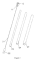
figure 1 de la planche 1/8 présente une vue en coupe du dispositif complet (prothèse et moyens d'insertion) - La
figure 2 de la planche 2/8 est une vue éclatée des moyens qui composent l'invention. - La
figure 3 de la planche 3/8 est une vue en perspective de la prothèse formée de deux parties distinctes. - La
figure 4 de la planche 3/8 est une vue en perspective de la prothèse apres réunion des 2 parties. - La
figure 5a de la planche 4/8 est une vue en coupe horizontale de la prothèse formée de ses 2 parties avant assemblage - La
figure 5b de planche 4/8 est une vue en coupe horizontale de la prothèse formée de ses 2 parties réunies - La
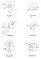
figure 6a de la planche 4/8 montre une vue en perspective d'une prothèse de forme différente à l'origine. - La
figure 6b de la planche 4/8 est la même prothèse assemblée la partie mâle ayant été introduite dans la partie femelle. - Les
figures 7a et 7b de la planche 4/8 représentent les mêmes situations que lesfigures 6a et b , la partie femelle étant dans ce cas un anneau fendu sectoriellement de part en part. - La
figure 8 de la planche 5/8 montre l'ensemble des moyens qui participent à l'invention avant l'introduction dans le disque intervertébral. - La
figure 9 de la planche 5/8 montre l'ensemble des moyens après introduction dans ledisque intervertébral de la partie femelle. - La
figure 10 de la planche 5/8 est la même prothèse que celle de lafigure 9 ,mais après introduction de la partie mâle dans la partie femelle. - La
figure 11 de la planche 5/8 représente la même prothèse une fois retirés certains moyens servant à l'insertion. - La
figure 12 de la planche 5/8 montre la prothèse une fois en place , les tiges de guidage ayant èté coupées - La
figure 13 de la planche 5/8 montre une vue en coupe longitudinale de la prothèse plaçée dans le disque intervertébral. - Les
figures 14 ,15 et 16 de la planche 6/8 montrent une prothèse dans laquelle la partie mâle est une variante qui permet une fixation sur l'os - La
figure 17 de la planche 7/8 donne les phases du procédé de mise en place. - Les
figures 18 et 19 de la planche 8/8 sont des vues en perpective de l'ensemble d'une autre réalisation de la prothèse montrant les détails avant insertion. - La
figure 20 de la planche 8/8 est une vue en coupe (en forme de bouchon de champagne) d'une prothèse partie mâle et femelle en place - La
figure 21 de la planche 8/8 montre la même prothèse une fois enlevées les tiges de guidage - La
figure 22 de la planche 8/8 est une vue en coupe verticale de la prothèse. - La
figure 23 de la planche 8/8 est une vue en coupe verticale de la prothèse .implantée - La prothèse de nucléus intervertébral (1) comprend dans une première forme de réalisation
un moyen 12 appellé partie femelle , fabriqué en matériau défor-mable élastiquement dont la forme peut être une sphère creuse aux pôles aplaties, formée:
d'une cavité centrale 121 reliée à une tige rigide 21 et
d'un orifice d'introduction 122
un moyen 11 partie mâle qui comporte une sphére pleine 111 déformable dont les fonctions principales sont: - d'écarter la partie femelle 12 pour s'introduire et venir épouser parfaitement la forme de la cavité 121 apres introduction
- d'être apte à supporter les efforts mécaniques imposés .
- Ce moyen 11 possède dans sa partie arrière une excroissance 113 dont la forme est déterminée pour venir s'encastrer dans l'ouverture 122 qui s'écarte par élasticité pendant l'introduction. Cette opération effectuée , la partie mâle 11 prend sa place de manière définitive et ne peut être expulsée de la partie femelle 12.
- La prothèse de nucléus 1 est introduite dans la cavité intervertébrale par un ensemble de moyens d'insertion 2 permettant son introduction , à savoir:
- la tige rigide 21 reliée au moyen 12 par l'intermédiaire d'une liaison souple 124
- des tubes 23 ,24 et 25 servant à introduire le moyen 1 dans la cavité.Le tube 23 contient la partie femelle 12 de la prothèse 1 comprimée avec sa tige de guidage 21; il contient également le tube 24.
- Le tube 24 contient la partie mâle 11 guidée par la tige 21 , ce moyen 24 servira de poussoir à la partie femelle 12 comprimée à l'intérieur du tube 23.
- Le tube 25 enfilé sur la tige 21 sert de poussoir à la partie mâle 11 vers la partie femelle 12.
- Le Procédé d'insertion 5 comprend 7 phases
phase 1 introduction dans le tube 24 de la partie mâle 11 enfilée sur la tige 21
phase 2 coulissement du tube 23 autour du tube 24, la partie femelle 12 est introduite dans le tube 23
phase 3: présentation du dispositif d'insertion 1 devant l'orifice de la cavité à combler
phase 4 poussée de la partie femelle 12 par le tube 24 (fig 9 )
phase 5 introduction du tube 25 enfilé sur la tige 21 pour amener la partie mâle 11 dans l'orifice 122 de la partie femelle 121
phase 6 poussée à l'aide du tube 25 de la partie mâle 11 dans l'orifice 122 pour encastrer le moyen 11 dans le moyen 12.
phase 7 les tubes 23,24,25 sont retirés , la tige 21 étant enlevée ,par exemple par coupure au niveau de la liaison souple 124, ce qui libère la prothèse 1 du dispositif d'insertion 2.Les formes des prothèses de nucléus 1 pièces mâles 11 et femelle 12 peuvent avoir plusieurs variantes , toujours compatibles avec le même procédé d'insertion 5. - La partie femelle 12 a un orifice 122 qui peut être soit une forme circulaire soit la forme d'une fente traversant sectoriellement la prothèse 12 de part en part qui se présente comme un anneau fendu.
- Il existe toujours dans cet orifice 122 un rétrécissement 123 qui va interdire à la partie mâle 11 d'être explusée une fois positionnée dans la partie femelle 12
- Les formes extérieures de l'enveloppe non contraintes peuvent varier , la fonction essentielle étant de s'adapter à la cavité intervertébrale à combler sans risque de glissement ou d'expulsion.
- La partie mâle 11 (
fig 14 et 15 ) peut comporter à son extrémité une excroissance 115 qui comporte une fixation 116 sur les os exemple : des trous laissant passer des vis de fixation , ceci afin de mieux garantir dans certains cas la non explusion de la prothèse.La partie femelle peut grâce à son adaptation de forme provenant de la nature de son matériau élastique a une capacité de déformation qui lui permet de passer au travers des tubes et orifices d'insertion qui ont des sections plus réduites, on peut apprécier le taux de réduction ou compression (rapport R entre les diamètres D et d avant et après mise en place dans le tube ) R est supérieur à 2 - Dans une autre forme de réalisation ( voir
figures 18, 19,20 21 et 22 ) la prothèse de nucléus 1 déformable élastiquement comprend deux parties ;
un moyen 12 appelé partie femelle ayant une forme d'anneau ouvert pour laisser rentrer une partie mâle 11, le moyen 12 comporte un filetage 127f recevant une tige de guidage 21 dont l'extrémité est filetée (filetage mâle 127m correspondant à 127f ), ladite tige rigide 21 permet de guider librement la partie mâle 11de la prothèse 1 jusqu'à son insertion et également de retirer la tige 21 par simple dévissage, une fois la prothèse 1 en place. - Le moyen 12 comprend un orifice 122 permettant l'introduction du moyen 11 (partie mâle 127a). Le moyen 11 a de préférence la forme d'un bouchon antiretour , il comporte une tête sphérique pleine 111 déformable ainsi qu'un corps cylindrique dépassant légèrement si et se trouvant à la périphérie de l'anneau.
- Dans cette solution , l'ancrage de la partie mâle 11 dans la partie femelle est assuré par un système anti-retour de clipsage des parties mâle 128m et femelle 128f , système intégré dans la forme des pièces lors de la fabrication.
- Lors de l'introduction , la partie mâle 11 écarte l'orifice 122 de l'anneau, ce dernier par élasticité vient ensuite se refermer sur la partie mâle 11. De plus (voir
figure 22 ) la tête sphérique de la partie male dépasse légèrement de l'épaisseur de l'anneau . Quand la prothèse est soumise aux sollicitations dynamiques, cette partie sphérique est comprimée la première, elle augmente ainsi la fonction antiretour rendant impossible l'expulsion de la partie male. - La partie femelle peut disposer d'un insert métallique recevant la tige filetée 127m qui est visible sous rayons X .Une fois la prothèse 1 en place ,la position de l'insert permet de vérifier la stabilité de la prothèse dans le temps, il permet également un démontage facile de la tige 21 une fois la prothèse installée.
- L'invention n'est pas limitée aux exemples décrits et représentés car diverses modifications peuvent y être apportées sans sortir de son cadre, defini par les revendications suivantes.
Claims (9)
- Prothèse de nucléus intervertébral (1) composée de deux parités fabriquées dans un matériau élastique déformable, caractérisée en ce qu'elle comprend:- une partie femelle (12) déformable comprenant une cavité centrale (121) apte à être reliée à une tige rigide (21), la cavité centrale (121) comportant un orifice (122) lui même déformable;- une partie mâle (11) comprenant une sphère pleine (111) déformable élastiquement en vue de venir se loger pour épouser la forme de la cavité centrale (121) grâce à l'orifice déformable (122), ceci pour former un bloc élastique non expulsable de son logement quand la prothèse est soumise aux efforts mécaniques imposes.
- Prothèse de nucléus intervertébral (1) selon la revendication 1, caractérisée en ce que la partie femelle (12) a la forme d'une sphère creuse aplatie aux pôles, et en ce que ledit orifice (122) a une forme circulaire, l'orifice possédant un rétrécissement (123) évitant l'expulsion après introduction de la partie mâle (11).
- Prothèse de nucléus intervertébral (1) selon la revendication 1, caractérisée en ce que la partie femelle (12) a la forme d'une sphère creuse aplatie aux pôles, et en ce que ledit orifice (122) est une fente (126) traversant de part en part sectoriellement l'épaisseur de la partie femelle (12) et possédant un rétrécissement (123) évitant l'expulsion après introduction de la partie mâle (11).
- Prothèse de nucléus intervertébral (1) selon l'une quelconque des précédentes revendications 2 ou 3 caractérisée en ce que la partis mâle (11) comporte une excroissance (115) à son extrémité qui comporte une fixation (116) permettant le passage de vis pour fixation sur l'os pour assurer un bon ancrage de la prothèse (1).
- Prothèse de nucléus intervertébral (1) selon la revendication 1, caractérisée en ce que la partie femelle (12) a une forme d'anneau ouvert pour laisser rentrer la partie mâle (11), ladite partie femelle (12) comportant un filetage (127f) pour recevoir une tige de guidage (21) dont l'extrémité est filetée.
- Prothèse de nucléus intervertébral (1) selon la revendication 5, caractérisée en ce que la partie mâle a la forme d'un bouchon de champagne jouant le rôle d'anti-retour comportant une tête sphérique pleine (111) déformable ainsi qu'un corps cylindrique dépassant légèrement et se trouvant à la périphérie de l'anneau.
- Prothèse de nucléus intervertébral (1) selon l'une quelconque des précédentes revendications 1 à 6, caractérisée en ce que la partie femelle (12) possède un insert qui permet sous visualisation de rayonnement X de vérifier la stabilité de ladite prothèse dans la temps ainsi que le démontage de la tige (21) une fois la prothèse installée.
- Combinaison d'une prothèse selon l'une quelconque des précédentes revendications 1 à 4, et d'un dispositif (3) de mise en place de ladite prothèse (1) caractérisée en ce que les moyens d'insertion (2) du dispositif (3) sont formés d'une tige (21) rigide reliée à la partie femelle (12) par une liaison souple (124) et de tubes (23, 24, et 25) servant à introduire la prothèse (1) de nucléus dans la cavité intervertébrale à combler.
- Combinaison d'une prothèse selon l'une quelconque des précédentes revendications 5 ou 6, et d'un dispositif (3) de mise en place de ladite prothèse (1) caractérisée en ce que les moyens d'insertion (2) du dispositif (3) comprennent une tige (21) rigide dont l'extrémité a un filetage mâle (127m) correspondent à le filetage (127f) de la partie femelle (12), ladite tige rigide (21) permettant également de guider librement la partie mâle (11) de la prothèse (1) jusqu'à son insertion et ensuite de pouvoir retirer la tige (21) par simple dévissage, une fois la prothèse (1) en place.
Applications Claiming Priority (3)
| Application Number | Priority Date | Filing Date | Title |
|---|---|---|---|
| FR0111905A FR2829689B1 (fr) | 2001-09-14 | 2001-09-14 | Prothese de nucleus et son dispositif d'insertion ainsi que son procede de mise en place |
| FR0111905 | 2001-09-14 | ||
| PCT/FR2002/003103 WO2003024368A1 (fr) | 2001-09-14 | 2002-09-12 | Prothese de nucleus intervertebral, son dispositif d'insertion, et son procede de mise en place |
Publications (2)
| Publication Number | Publication Date |
|---|---|
| EP1432370A1 EP1432370A1 (fr) | 2004-06-30 |
| EP1432370B1 true EP1432370B1 (fr) | 2010-03-17 |
Family
ID=8867285
Family Applications (1)
| Application Number | Title | Priority Date | Filing Date |
|---|---|---|---|
| EP02798760A Expired - Lifetime EP1432370B1 (fr) | 2001-09-14 | 2002-09-12 | Prothese de nucleus intervertebral et son dispositif d'insertion |
Country Status (8)
| Country | Link |
|---|---|
| US (1) | US7267692B2 (fr) |
| EP (1) | EP1432370B1 (fr) |
| JP (1) | JP2005509467A (fr) |
| KR (1) | KR20040050895A (fr) |
| AT (1) | ATE460909T1 (fr) |
| DE (1) | DE60235707D1 (fr) |
| FR (1) | FR2829689B1 (fr) |
| WO (1) | WO2003024368A1 (fr) |
Families Citing this family (21)
| Publication number | Priority date | Publication date | Assignee | Title |
|---|---|---|---|---|
| US8083798B2 (en) | 2005-04-04 | 2011-12-27 | Warsaw Orthopedic, Inc. | Non-circular stabilization sphere and method |
| US7988735B2 (en) * | 2005-06-15 | 2011-08-02 | Matthew Yurek | Mechanical apparatus and method for delivering materials into the inter-vertebral body space for nucleus replacement |
| US8021426B2 (en) * | 2005-06-15 | 2011-09-20 | Ouroboros Medical, Inc. | Mechanical apparatus and method for artificial disc replacement |
| WO2007008983A2 (fr) * | 2005-07-11 | 2007-01-18 | Kyphon, Inc. | Systemes et procedes de realisation de protheses |
| US20070050028A1 (en) * | 2005-08-26 | 2007-03-01 | Conner E S | Spinal implants and methods of providing dynamic stability to the spine |
| US20070244562A1 (en) * | 2005-08-26 | 2007-10-18 | Magellan Spine Technologies, Inc. | Spinal implants and methods of providing dynamic stability to the spine |
| US8900306B2 (en) * | 2006-09-26 | 2014-12-02 | DePuy Synthes Products, LLC | Nucleus anti-expulsion devices and methods |
| US8114160B2 (en) * | 2006-12-22 | 2012-02-14 | Pioneer Surgical Technology, Inc. | Implant retention device and method |
| US20090299479A1 (en) * | 2007-10-19 | 2009-12-03 | Jones Robert J | Suture guided implant |
| EP2219561A4 (fr) * | 2007-11-19 | 2012-02-08 | Magellan Spine Technologies Inc | Implants vertébraux et procédés |
| US8518113B2 (en) * | 2008-05-20 | 2013-08-27 | Warsaw Othopedic, Inc. | Intervertebral implant and methods of implantation and manufacture |
| US9066816B2 (en) | 2009-01-21 | 2015-06-30 | Warsaw Orthopedic, Inc. | Spinal nucleus replacement implants |
| US9011539B2 (en) * | 2009-01-21 | 2015-04-21 | Warsaw Orthopedic, Inc. | Spinal nucleus replacement implant |
| EP2379017A4 (fr) * | 2009-01-21 | 2013-06-19 | Warsaw Orthopedic Inc | Implants de remplacement du noyau spinal |
| US8292962B2 (en) | 2009-03-04 | 2012-10-23 | Warsaw Orthopedic, Inc. | Spinal nucleus replacement implants |
| US8828082B2 (en) | 2009-07-09 | 2014-09-09 | R Tree Innovations, Llc | Inter-body implant |
| US8911439B2 (en) * | 2009-11-11 | 2014-12-16 | Holaira, Inc. | Non-invasive and minimally invasive denervation methods and systems for performing the same |
| US9402736B2 (en) * | 2010-07-12 | 2016-08-02 | Alphatec Spine, Inc. | Interbody fusion implant and related methods |
| EP2777628B1 (fr) * | 2013-03-15 | 2018-02-28 | Neos Surgery, S.L. | Dispositif pour réparer un disque intervertébral |
| US8932358B1 (en) * | 2013-10-07 | 2015-01-13 | Daniel Nehls | Anterior intervertebral spacer and integrated plate assembly and methods of use |
| USD742509S1 (en) * | 2014-12-15 | 2015-11-03 | Robert G. Anderson | Prosthesis insertion collar drape |
Citations (1)
| Publication number | Priority date | Publication date | Assignee | Title |
|---|---|---|---|---|
| EP0919209A1 (fr) * | 1993-04-20 | 1999-06-02 | Howmedica Inc. | Noyau de disque intervertébral en hydrogel à renflement latéral réduit |
Family Cites Families (38)
| Publication number | Priority date | Publication date | Assignee | Title |
|---|---|---|---|---|
| US3875595A (en) * | 1974-04-15 | 1975-04-08 | Edward C Froning | Intervertebral disc prosthesis and instruments for locating same |
| US4433440A (en) * | 1979-02-26 | 1984-02-28 | Cohen I Kelman | Prosthesis formed by inner and outer inflatable containers |
| JPS57144756A (en) * | 1981-03-04 | 1982-09-07 | Koken Kk | Impermeable laminated film |
| DE3214772C1 (de) * | 1982-04-21 | 1983-08-11 | Otto Bock, Orthopädische Industrie KG, 3428 Duderstadt | Rohrmuffe zur Aufnahme und Befestigung von Rohr-Skeletteilen von kuenstlichen Gliedmassen |
| FR2530498A1 (fr) | 1982-07-26 | 1984-01-27 | Sba Chimie | Dispositif de montage de rampes adaptees sur des materiels agricoles et industriels, en particulier des rampes de pulverisation |
| US4648880A (en) * | 1984-08-30 | 1987-03-10 | Daniel Brauman | Implantable prosthetic devices |
| US4636213A (en) * | 1985-01-24 | 1987-01-13 | Pakiam Anthony I | Implantable prosthesis |
| US4969888A (en) * | 1989-02-09 | 1990-11-13 | Arie Scholten | Surgical protocol for fixation of osteoporotic bone using inflatable device |
| US5047055A (en) * | 1990-12-21 | 1991-09-10 | Pfizer Hospital Products Group, Inc. | Hydrogel intervertebral disc nucleus |
| EP0621020A1 (fr) * | 1993-04-21 | 1994-10-26 | SULZER Medizinaltechnik AG | Prothèse intervertébrale et procédé d'implantation d'une telle prothèse |
| DE4323595C1 (de) * | 1993-07-15 | 1994-07-07 | Eska Medical Gmbh & Co | Bandscheibenteilersatz als Entlastungsteil |
| ID26008A (id) | 1993-09-02 | 1995-03-16 | Riviana Foods Inc | ALAT MASAK KUKUS (Pecahan dari P941466) |
| RU2147213C1 (ru) * | 1994-01-26 | 2000-04-10 | А. Рейли Марк | Усовершенствованное наполняемое устройство для использования в хирургическом протоколе применительно к фиксации кости |
| US6093207A (en) * | 1994-03-18 | 2000-07-25 | Pisharodi; Madhavan | Middle expanded, removable intervertebral disk stabilizer disk |
| US5697977A (en) * | 1994-03-18 | 1997-12-16 | Pisharodi; Madhavan | Method and apparatus for spondylolisthesis reduction |
| US5571189A (en) * | 1994-05-20 | 1996-11-05 | Kuslich; Stephen D. | Expandable fabric implant for stabilizing the spinal motion segment |
| JP3621424B2 (ja) * | 1995-10-20 | 2005-02-16 | ジンテーズ アクチエンゲゼルシャフト クール | ケージと回転体を有する椎間インプラント |
| CA2242645A1 (fr) * | 1995-12-08 | 1997-06-12 | Robert S. Bray, Jr. | Dispositif de stabilisation anterieure |
| US5645597A (en) * | 1995-12-29 | 1997-07-08 | Krapiva; Pavel I. | Disc replacement method and apparatus |
| ES2150405T1 (es) * | 1997-04-25 | 2000-12-01 | Stryker France Sa | Implantes intersomaticos en dos partes. |
| US5800549A (en) * | 1997-04-30 | 1998-09-01 | Howmedica Inc. | Method and apparatus for injecting an elastic spinal implant |
| US5972015A (en) * | 1997-08-15 | 1999-10-26 | Kyphon Inc. | Expandable, asymetric structures for deployment in interior body regions |
| GB9714580D0 (en) * | 1997-07-10 | 1997-09-17 | Wardlaw Douglas | Prosthetic intervertebral disc nucleus |
| US6168631B1 (en) * | 1997-08-29 | 2001-01-02 | Kinetikos Medical, Inc. | Subtalar implant system and method for insertion and removal |
| BR9805340B1 (pt) * | 1998-12-14 | 2009-01-13 | inserto de expansço variÁvel para estabilizaÇço de coluna vertebral. | |
| US6102950A (en) * | 1999-01-19 | 2000-08-15 | Vaccaro; Alex | Intervertebral body fusion device |
| US6419704B1 (en) * | 1999-10-08 | 2002-07-16 | Bret Ferree | Artificial intervertebral disc replacement methods and apparatus |
| US6425919B1 (en) * | 1999-08-18 | 2002-07-30 | Intrinsic Orthopedics, Inc. | Devices and methods of vertebral disc augmentation |
| US20030004574A1 (en) * | 1999-10-08 | 2003-01-02 | Ferree Bret A. | Disc and annulus augmentation using biologic tissue |
| US6332894B1 (en) * | 2000-03-07 | 2001-12-25 | Zimmer, Inc. | Polymer filled spinal fusion cage |
| US20020128717A1 (en) * | 2000-03-09 | 2002-09-12 | Alfaro Arthur A. | Anterior lumbar spacer |
| US7018416B2 (en) * | 2000-07-06 | 2006-03-28 | Zimmer Spine, Inc. | Bone implants and methods |
| US6620196B1 (en) | 2000-08-30 | 2003-09-16 | Sdgi Holdings, Inc. | Intervertebral disc nucleus implants and methods |
| US6468311B2 (en) * | 2001-01-22 | 2002-10-22 | Sdgi Holdings, Inc. | Modular interbody fusion implant |
| US20020147497A1 (en) * | 2001-04-06 | 2002-10-10 | Integrated Vascular Systems, Inc. | Methods for treating spinal discs |
| US6558424B2 (en) * | 2001-06-28 | 2003-05-06 | Depuy Acromed | Modular anatomic fusion device |
| US6733533B1 (en) * | 2002-11-19 | 2004-05-11 | Zimmer Technology, Inc. | Artificial spinal disc |
| US7004971B2 (en) | 2002-12-31 | 2006-02-28 | Depuy Acromed, Inc. | Annular nucleus pulposus replacement |
-
2001
- 2001-09-14 FR FR0111905A patent/FR2829689B1/fr not_active Expired - Fee Related
-
2002
- 2002-09-12 WO PCT/FR2002/003103 patent/WO2003024368A1/fr active Application Filing
- 2002-09-12 EP EP02798760A patent/EP1432370B1/fr not_active Expired - Lifetime
- 2002-09-12 AT AT02798760T patent/ATE460909T1/de not_active IP Right Cessation
- 2002-09-12 KR KR10-2004-7003764A patent/KR20040050895A/ko not_active Application Discontinuation
- 2002-09-12 DE DE60235707T patent/DE60235707D1/de not_active Expired - Lifetime
- 2002-09-12 JP JP2003528268A patent/JP2005509467A/ja active Pending
-
2004
- 2004-03-11 US US10/800,083 patent/US7267692B2/en not_active Expired - Fee Related
Patent Citations (1)
| Publication number | Priority date | Publication date | Assignee | Title |
|---|---|---|---|---|
| EP0919209A1 (fr) * | 1993-04-20 | 1999-06-02 | Howmedica Inc. | Noyau de disque intervertébral en hydrogel à renflement latéral réduit |
Also Published As
| Publication number | Publication date |
|---|---|
| FR2829689A1 (fr) | 2003-03-21 |
| JP2005509467A (ja) | 2005-04-14 |
| KR20040050895A (ko) | 2004-06-17 |
| ATE460909T1 (de) | 2010-04-15 |
| US7267692B2 (en) | 2007-09-11 |
| WO2003024368A1 (fr) | 2003-03-27 |
| US20050015151A1 (en) | 2005-01-20 |
| EP1432370A1 (fr) | 2004-06-30 |
| FR2829689B1 (fr) | 2004-06-25 |
| DE60235707D1 (de) | 2010-04-29 |
Similar Documents
| Publication | Publication Date | Title |
|---|---|---|
| EP1432370B1 (fr) | Prothese de nucleus intervertebral et son dispositif d'insertion | |
| CA2287523C (fr) | Implants intersomatiques en deux parties | |
| CA2266126C (fr) | Cage d'osteosynthese expansive | |
| EP0871419B1 (fr) | Implant intervertebral du type cage intersomatique | |
| EP3086729B1 (fr) | Système d'implant intravertébral expansible avec fixation pédiculaire postérieure | |
| FR2797179A1 (fr) | Prothese nucleaire intervertebrale et son procede chirurgical d'implantation | |
| FR2697744A1 (fr) | Instrumentation d'ostéosynthèse rachidienne par voie antérieure. | |
| CA2377030A1 (fr) | Organe d'ancrage avec cale | |
| FR2763836A1 (fr) | Cage intervertebrale cervicale | |
| FR2623082A1 (fr) | Cheville artificielle par la fixation intra-osseuse de prothese et renforts ligamentaires, ainsi que l'impacteur associe comportant des moyens de maintien de ladite cheville | |
| FR2811543A1 (fr) | Implant intersomatique | |
| FR2660856A1 (fr) | Prothese radio-cubitale inferieure. | |
| EP3310282B1 (fr) | Implant pour la fixation d'éléments osseux | |
| FR2760355A1 (fr) | Dispositif formant cage intersomatique a solidarisation provisoire interne d'un outil de vissage | |
| WO2005065595A1 (fr) | Prothese de disque intervertebral | |
| FR2796268A1 (fr) | Dispositif de maintien d'une ossature permettant de recevoir un produit de maintien et de comblement sans risque d'epandage de ce dernier a l'interieur du corps humain | |
| EP4132391B1 (fr) | Implant d'ancrage osseux à stabilisation corticale | |
| WO2005089679A1 (fr) | Prothese d’annulus intervertebral | |
| FR3109076A1 (fr) | Implant d’ancrage osseux à extrac tion facilitée | |
| FR2622791A1 (fr) | Prothese du type femoral | |
| FR2866227A1 (fr) | Prothese d'anulus intervertebral | |
| EP2389903B1 (fr) | Système pour réaliser une arthrodèse entre deux vertèbres et ancillaires de pose | |
| FR2923158A1 (fr) | Implant intervertebral permettant d'immobiliser une vertebre par rapport a une autre et instrument de pose de cet implant. | |
| EP1861048A1 (fr) | Prothese de disque intervertebral amortissante et adhesive | |
| FR2952296A1 (fr) | Dispositif et procede de fixation d'un tissu lamellaire sur un os |
Legal Events
| Date | Code | Title | Description |
|---|---|---|---|
| PUAI | Public reference made under article 153(3) epc to a published international application that has entered the european phase |
Free format text: ORIGINAL CODE: 0009012 |
|
| 17P | Request for examination filed |
Effective date: 20040322 |
|
| AK | Designated contracting states |
Kind code of ref document: A1 Designated state(s): AT BE BG CH CY CZ DE DK EE ES FI FR GB GR IE IT LI LU MC NL PT SE SK TR |
|
| 17Q | First examination report despatched |
Effective date: 20060803 |
|
| RTI1 | Title (correction) |
Free format text: NUCLEUS PROSTHESIS AND INSERTION DEVICE THEREFOR |
|
| GRAP | Despatch of communication of intention to grant a patent |
Free format text: ORIGINAL CODE: EPIDOSNIGR1 |
|
| GRAS | Grant fee paid |
Free format text: ORIGINAL CODE: EPIDOSNIGR3 |
|
| GRAA | (expected) grant |
Free format text: ORIGINAL CODE: 0009210 |
|
| AK | Designated contracting states |
Kind code of ref document: B1 Designated state(s): AT BE BG CH CY CZ DE DK EE ES FI FR GB GR IE IT LI LU MC NL PT SE SK TR |
|
| REG | Reference to a national code |
Ref country code: GB Ref legal event code: FG4D Free format text: NOT ENGLISH |
|
| REG | Reference to a national code |
Ref country code: CH Ref legal event code: EP |
|
| REG | Reference to a national code |
Ref country code: IE Ref legal event code: FG4D |
|
| REF | Corresponds to: |
Ref document number: 60235707 Country of ref document: DE Date of ref document: 20100429 Kind code of ref document: P |
|
| REG | Reference to a national code |
Ref country code: NL Ref legal event code: VDEP Effective date: 20100317 |
|
| PG25 | Lapsed in a contracting state [announced via postgrant information from national office to epo] |
Ref country code: AT Free format text: LAPSE BECAUSE OF FAILURE TO SUBMIT A TRANSLATION OF THE DESCRIPTION OR TO PAY THE FEE WITHIN THE PRESCRIBED TIME-LIMIT Effective date: 20100317 Ref country code: FI Free format text: LAPSE BECAUSE OF FAILURE TO SUBMIT A TRANSLATION OF THE DESCRIPTION OR TO PAY THE FEE WITHIN THE PRESCRIBED TIME-LIMIT Effective date: 20100317 |
|
| REG | Reference to a national code |
Ref country code: IE Ref legal event code: FD4D |
|
| PG25 | Lapsed in a contracting state [announced via postgrant information from national office to epo] |
Ref country code: NL Free format text: LAPSE BECAUSE OF FAILURE TO SUBMIT A TRANSLATION OF THE DESCRIPTION OR TO PAY THE FEE WITHIN THE PRESCRIBED TIME-LIMIT Effective date: 20100317 Ref country code: GR Free format text: LAPSE BECAUSE OF FAILURE TO SUBMIT A TRANSLATION OF THE DESCRIPTION OR TO PAY THE FEE WITHIN THE PRESCRIBED TIME-LIMIT Effective date: 20100618 Ref country code: ES Free format text: LAPSE BECAUSE OF FAILURE TO SUBMIT A TRANSLATION OF THE DESCRIPTION OR TO PAY THE FEE WITHIN THE PRESCRIBED TIME-LIMIT Effective date: 20100628 Ref country code: EE Free format text: LAPSE BECAUSE OF FAILURE TO SUBMIT A TRANSLATION OF THE DESCRIPTION OR TO PAY THE FEE WITHIN THE PRESCRIBED TIME-LIMIT Effective date: 20100317 Ref country code: CY Free format text: LAPSE BECAUSE OF FAILURE TO SUBMIT A TRANSLATION OF THE DESCRIPTION OR TO PAY THE FEE WITHIN THE PRESCRIBED TIME-LIMIT Effective date: 20100317 Ref country code: SE Free format text: LAPSE BECAUSE OF FAILURE TO SUBMIT A TRANSLATION OF THE DESCRIPTION OR TO PAY THE FEE WITHIN THE PRESCRIBED TIME-LIMIT Effective date: 20100317 |
|
| PG25 | Lapsed in a contracting state [announced via postgrant information from national office to epo] |
Ref country code: SK Free format text: LAPSE BECAUSE OF FAILURE TO SUBMIT A TRANSLATION OF THE DESCRIPTION OR TO PAY THE FEE WITHIN THE PRESCRIBED TIME-LIMIT Effective date: 20100317 Ref country code: BG Free format text: LAPSE BECAUSE OF FAILURE TO SUBMIT A TRANSLATION OF THE DESCRIPTION OR TO PAY THE FEE WITHIN THE PRESCRIBED TIME-LIMIT Effective date: 20100617 Ref country code: CZ Free format text: LAPSE BECAUSE OF FAILURE TO SUBMIT A TRANSLATION OF THE DESCRIPTION OR TO PAY THE FEE WITHIN THE PRESCRIBED TIME-LIMIT Effective date: 20100317 |
|
| PLBE | No opposition filed within time limit |
Free format text: ORIGINAL CODE: 0009261 |
|
| STAA | Information on the status of an ep patent application or granted ep patent |
Free format text: STATUS: NO OPPOSITION FILED WITHIN TIME LIMIT |
|
| PG25 | Lapsed in a contracting state [announced via postgrant information from national office to epo] |
Ref country code: PT Free format text: LAPSE BECAUSE OF FAILURE TO SUBMIT A TRANSLATION OF THE DESCRIPTION OR TO PAY THE FEE WITHIN THE PRESCRIBED TIME-LIMIT Effective date: 20100719 Ref country code: IE Free format text: LAPSE BECAUSE OF FAILURE TO SUBMIT A TRANSLATION OF THE DESCRIPTION OR TO PAY THE FEE WITHIN THE PRESCRIBED TIME-LIMIT Effective date: 20100317 Ref country code: DK Free format text: LAPSE BECAUSE OF FAILURE TO SUBMIT A TRANSLATION OF THE DESCRIPTION OR TO PAY THE FEE WITHIN THE PRESCRIBED TIME-LIMIT Effective date: 20100317 |
|
| 26N | No opposition filed |
Effective date: 20101220 |
|
| BERE | Be: lapsed |
Owner name: FORTIN, FREDERIC Effective date: 20100930 |
|
| PG25 | Lapsed in a contracting state [announced via postgrant information from national office to epo] |
Ref country code: IT Free format text: LAPSE BECAUSE OF FAILURE TO SUBMIT A TRANSLATION OF THE DESCRIPTION OR TO PAY THE FEE WITHIN THE PRESCRIBED TIME-LIMIT Effective date: 20100317 |
|
| PG25 | Lapsed in a contracting state [announced via postgrant information from national office to epo] |
Ref country code: MC Free format text: LAPSE BECAUSE OF NON-PAYMENT OF DUE FEES Effective date: 20100930 |
|
| REG | Reference to a national code |
Ref country code: CH Ref legal event code: PL |
|
| GBPC | Gb: european patent ceased through non-payment of renewal fee |
Effective date: 20100912 |
|
| REG | Reference to a national code |
Ref country code: FR Ref legal event code: ST Effective date: 20110531 |
|
| REG | Reference to a national code |
Ref country code: DE Ref legal event code: R119 Ref document number: 60235707 Country of ref document: DE Effective date: 20110401 |
|
| PG25 | Lapsed in a contracting state [announced via postgrant information from national office to epo] |
Ref country code: FR Free format text: LAPSE BECAUSE OF NON-PAYMENT OF DUE FEES Effective date: 20100930 Ref country code: CH Free format text: LAPSE BECAUSE OF NON-PAYMENT OF DUE FEES Effective date: 20100930 Ref country code: LI Free format text: LAPSE BECAUSE OF NON-PAYMENT OF DUE FEES Effective date: 20100930 Ref country code: DE Free format text: LAPSE BECAUSE OF NON-PAYMENT OF DUE FEES Effective date: 20110401 Ref country code: BE Free format text: LAPSE BECAUSE OF NON-PAYMENT OF DUE FEES Effective date: 20100930 |
|
| PG25 | Lapsed in a contracting state [announced via postgrant information from national office to epo] |
Ref country code: GB Free format text: LAPSE BECAUSE OF NON-PAYMENT OF DUE FEES Effective date: 20100912 |
|
| PG25 | Lapsed in a contracting state [announced via postgrant information from national office to epo] |
Ref country code: LU Free format text: LAPSE BECAUSE OF NON-PAYMENT OF DUE FEES Effective date: 20100912 |
|
| PG25 | Lapsed in a contracting state [announced via postgrant information from national office to epo] |
Ref country code: TR Free format text: LAPSE BECAUSE OF FAILURE TO SUBMIT A TRANSLATION OF THE DESCRIPTION OR TO PAY THE FEE WITHIN THE PRESCRIBED TIME-LIMIT Effective date: 20100317 |