EP1431865A2 - Electrical control unit for an automobile - Google Patents
Electrical control unit for an automobile Download PDFInfo
- Publication number
- EP1431865A2 EP1431865A2 EP20030029004 EP03029004A EP1431865A2 EP 1431865 A2 EP1431865 A2 EP 1431865A2 EP 20030029004 EP20030029004 EP 20030029004 EP 03029004 A EP03029004 A EP 03029004A EP 1431865 A2 EP1431865 A2 EP 1431865A2
- Authority
- EP
- European Patent Office
- Prior art keywords
- control unit
- electrical control
- microcomputer
- automobile
- power supply
- Prior art date
- Legal status (The legal status is an assumption and is not a legal conclusion. Google has not performed a legal analysis and makes no representation as to the accuracy of the status listed.)
- Granted
Links
- 238000004891 communication Methods 0.000 claims description 36
- 239000000446 fuel Substances 0.000 claims description 12
- 239000004065 semiconductor Substances 0.000 claims description 11
- 230000003213 activating effect Effects 0.000 claims description 7
- WHXSMMKQMYFTQS-UHFFFAOYSA-N Lithium Chemical compound [Li] WHXSMMKQMYFTQS-UHFFFAOYSA-N 0.000 claims description 4
- 229910052744 lithium Inorganic materials 0.000 claims description 4
- 238000002347 injection Methods 0.000 claims description 3
- 239000007924 injection Substances 0.000 claims description 3
- 230000006866 deterioration Effects 0.000 claims 1
- 238000000034 method Methods 0.000 description 22
- 230000003247 decreasing effect Effects 0.000 description 12
- 238000010586 diagram Methods 0.000 description 10
- 230000004913 activation Effects 0.000 description 5
- 230000000737 periodic effect Effects 0.000 description 4
- 230000001276 controlling effect Effects 0.000 description 3
- 230000002542 deteriorative effect Effects 0.000 description 3
- 239000000203 mixture Substances 0.000 description 3
- 238000005259 measurement Methods 0.000 description 2
- 230000002093 peripheral effect Effects 0.000 description 2
- 239000010453 quartz Substances 0.000 description 2
- VYPSYNLAJGMNEJ-UHFFFAOYSA-N silicon dioxide Inorganic materials O=[Si]=O VYPSYNLAJGMNEJ-UHFFFAOYSA-N 0.000 description 2
- 230000002618 waking effect Effects 0.000 description 2
- 239000004020 conductor Substances 0.000 description 1
- 238000001514 detection method Methods 0.000 description 1
- 230000000694 effects Effects 0.000 description 1
- 230000000415 inactivating effect Effects 0.000 description 1
- 230000007774 longterm Effects 0.000 description 1
- 230000001105 regulatory effect Effects 0.000 description 1
- 230000009291 secondary effect Effects 0.000 description 1
- 238000011144 upstream manufacturing Methods 0.000 description 1
Images


Classifications
-
- F—MECHANICAL ENGINEERING; LIGHTING; HEATING; WEAPONS; BLASTING
- F02—COMBUSTION ENGINES; HOT-GAS OR COMBUSTION-PRODUCT ENGINE PLANTS
- F02D—CONTROLLING COMBUSTION ENGINES
- F02D41/00—Electrical control of supply of combustible mixture or its constituents
- F02D41/02—Circuit arrangements for generating control signals
- F02D41/04—Introducing corrections for particular operating conditions
- F02D41/06—Introducing corrections for particular operating conditions for engine starting or warming up
- F02D41/062—Introducing corrections for particular operating conditions for engine starting or warming up for starting
-
- F—MECHANICAL ENGINEERING; LIGHTING; HEATING; WEAPONS; BLASTING
- F02—COMBUSTION ENGINES; HOT-GAS OR COMBUSTION-PRODUCT ENGINE PLANTS
- F02D—CONTROLLING COMBUSTION ENGINES
- F02D41/00—Electrical control of supply of combustible mixture or its constituents
- F02D41/02—Circuit arrangements for generating control signals
- F02D41/14—Introducing closed-loop corrections
- F02D41/1438—Introducing closed-loop corrections using means for determining characteristics of the combustion gases; Sensors therefor
- F02D41/1493—Details
- F02D41/1494—Control of sensor heater
-
- F—MECHANICAL ENGINEERING; LIGHTING; HEATING; WEAPONS; BLASTING
- F02—COMBUSTION ENGINES; HOT-GAS OR COMBUSTION-PRODUCT ENGINE PLANTS
- F02D—CONTROLLING COMBUSTION ENGINES
- F02D41/00—Electrical control of supply of combustible mixture or its constituents
- F02D41/24—Electrical control of supply of combustible mixture or its constituents characterised by the use of digital means
- F02D41/26—Electrical control of supply of combustible mixture or its constituents characterised by the use of digital means using computer, e.g. microprocessor
-
- G—PHYSICS
- G06—COMPUTING; CALCULATING OR COUNTING
- G06F—ELECTRIC DIGITAL DATA PROCESSING
- G06F1/00—Details not covered by groups G06F3/00 - G06F13/00 and G06F21/00
- G06F1/26—Power supply means, e.g. regulation thereof
- G06F1/32—Means for saving power
- G06F1/3203—Power management, i.e. event-based initiation of a power-saving mode
- G06F1/3206—Monitoring of events, devices or parameters that trigger a change in power modality
- G06F1/3215—Monitoring of peripheral devices
-
- F—MECHANICAL ENGINEERING; LIGHTING; HEATING; WEAPONS; BLASTING
- F02—COMBUSTION ENGINES; HOT-GAS OR COMBUSTION-PRODUCT ENGINE PLANTS
- F02N—STARTING OF COMBUSTION ENGINES; STARTING AIDS FOR SUCH ENGINES, NOT OTHERWISE PROVIDED FOR
- F02N2300/00—Control related aspects of engine starting
- F02N2300/30—Control related aspects of engine starting characterised by the use of digital means
- F02N2300/302—Control related aspects of engine starting characterised by the use of digital means using data communication
Definitions
- the present invention relates to an electrical control unit for an automobile. Especially, the present invention relates to an electrical control unit for an automobile started by a wake-up signal other than the ignition switch signal, even when the ignition switch is cut off.
- Microcomputer is indicated when the wake-up starting circuit generates the wake-up trigger signal by inputting external switch, and this signal is input to the interrupt terminal of microcomputer and the composition that wake-up is done is disclosed in Japanese Patent Application Laid-Open No. 2002-108519.
- the conventional electrical control unit needs to keep supplying the electric current from the battery when the ignition switch is cut off, because it cannot start according to a wake-up signal other than an ignition switch signal.
- the electric current consumption at this sleep that is, the standby electric current is large, the amount of the electrical discharge from the battery increases when the automobile is not driven for a long term. As a result, the possibility that the engine cannot be started may occur. It is required to decrease the standby electric current of an individual electrical control unit as much as possible because various equipment such as a lot of electrical control units are installed in the present automobile.
- the standby electric current of the microcomputer is small in the conventional electrical control unit of the body system in which the circuit scale of the microcomputer is comparatively small.
- the microcomputer with high performance and multi-function is installed in the electrical control unit which controls the powertrain such as an engine, etc. Therefore, the leakage current is larger because the logic scale is larger than that of the microcomputer for the body system control.
- the standby electric current of the microcomputer and thus the standby electric current of the electrical control unit increases. Further, because it is necessary to operate the same power supply circuit as the power supply circuit which supplies the electric current to the CPU core at the normal operation in order to supply the standby electric current to the CPU core, the standby electric current will be become larger.
- the wake-up method by which the wake-up signal is input to the interrupt terminal of the microcomputer is undesirable as described above.
- the consumption current of the timer module installed in the microcomputer has the tendency that increases by the influence such as the leak to the modules in the surrounding, and it relates to the increase in the standby electric current, although the method by which the wake-up signal is output by using the timer module installed in the microcomputer is thought.
- An object of the present invention is to provide an electrical control unit for an automobile of which the standby electric current is smaller.
- the present invention adopts an electrical control unit for an automobile comprised of a microcomputer, an input circuit, a driver circuit and/or a power supply circuit.
- Said microcomputer can be started by a wake-up signal other than the ignition switch signal.
- said microcomputer can be started by shifting said power supply circuit from an inert state to an active state to generate the voltage by which said microcomputer is operated by a wake-up signal from the circuit other than the ignition switch, even when the ignition switch of said automobile is cut off, and the predetermined processing is executed by the microcomputer.
- the standby electric current can be greatly decreased.
- the microcomputer is waked up by providing a wake-up trigger signal from a wake-up starting circuit, and inputting this signal to the interrupt terminal of the microcomputer when the external switch signal is input.
- the electrical control unit performs the activation processing of a cold start device (CSD) by energizing the heater of the equipment before the ignition switch is connected.
- CSD cold start device
- An electrical control unit for an automobile can comprise a microcomputer, an input circuit, a driver circuit and/or a power supply circuit.
- Said microcomputer can be started by a wake-up signal other than the ignition switch signal.
- Said microcomputer can be started by shifting said power supply circuit from an inert state to an active state to generate the voltage by which said microcomputer is operated by a wake-up signal from the circuit other than the ignition switch even when the ignition switch of said automobile is cut off, and the predetermined processing is executed by the microcomputer.
- Said wake-up signal can be a signal transmitted at least from either the electrical control unit for the keyless entry, or an electrical control unit for the door lock management by which it can be perceived whether the car owner gets on or have gotten on the automobile.
- the electrical control unit for an automobile can start said microcomputer by activating said power supply circuit according to this wake-up signal, and can begin to turn on any one of an airflow sensor, an O 2 sensor, a fuel pump or various heater devices in advance of the connection of the ignition switch.
- another form of said wake-up signal can be a signal output by the timer module which is built into the electrical control unit for the automobile or an electrical control unit other than one concerned, and may be composed of ai least a counter, a wake-up timing setting register and/or a comparator, when the value of said counter reaches the value set in said wake-up timing setting register beforehand.
- the electrical control unit for an automobile can start said microcomputer by activating said power supply circuit according to this wake-up signal to monitor the states of various equipment of the automobile concerned or control the equipment concerned if necessary.
- Said microcomputer can make said power supply circuit inert after the execution of the processing is completed, or after the state that the ignition switch is not connected continues during the predetermined time after the completion of the execution of said predetermined processing, and shuts down the electrical control unit for the automobile concerned again.
- the electrical control unit for the automobile can calculate the period elapsed after the ignition switch is cut off at the time when the ignition switch is connected by using the count value of said timer module to estimate the amount of the fuel leakage from the injector during the period concerned. Further, by using this, it can correct fuel consumption at the engine start or estimate the level of deteriorating with the passage of time of various equipment of the automobile concerned to control the automobile.
- an electrical control unit for the automobile can comprise a microcomputer, an input circuit, a driver circuit, and a power supply circuit, and can be started by a wake-up signal from the circuit other than the ignition switch even when the ignition switch of said automobile is cut off.
- said power supply circuit can be a semiconductor IC that can integrate the following components, a first regulator which can generate the voltage to operate said microcomputer by inputting said ignition switch signal or said wake-up signal, a second regulator which can operate even when said ignition switch is cut off, an OR circuit that can activate said first regulator by using either the ignition switch signal or one of said plural wake-up signals, a start factor determining means which can distinguish whether said first regulator is activated by which signal of the ignition switch signal and/or one of plural wake-up signals, a communication driver which can transmit and receive the communication signal with an outside electrical control unit through a communications line, a latch circuit that can latch the wake-up signals transmitted from the outside electrical control unit through said communications line, a reset circuit which can generate a reset signal to said microcomputer, a watchdog timer that can prevent the runaway of the active program in said microcomputer, and a serial communications module which can communicate serially with said microcomputer.
- the start factor distinguished by the start factor determining means of said semiconductor IC can be transmitted to said microcomputer through said serial communications
- said semiconductor IC can include a counter, a wake-up timing setting register, a comparator, and/or a timer module which outputs the wake-up signal when the value of said counter reaches the value set in said wake-up timing setting register beforehand is integrated therewith.
- said microcomputer can set the value of said wake-up timing setting register of said timer module through the serial communications module of said semiconductor IC, or said timer module can transmit the counter value at that time to said microcomputer.
- the electrical control unit for the automobile provides inside with the power supply to operate at least said timer module for the period when the power supply is not supplied from the outside.
- Said semiconductor IC has the power supply switch means.
- Said switch means supplies a current to said timer module either from said outside power supply for the period when the power supply is supplied from the outside to said electrical control unit for the automobile, or from the power supply provided in said electrical control unit for the automobile for the period when the power supply is not supplied from the outside.
- the power supply such as lithium electric cell can be provided in the electrical control unit to operate said timer module at least even when the power supply is not supplied from the outside to the electrical control unit for an automobile.
- the electrical control unit for an automobile has the feature that this power supply switch means can be integrated into the semiconductor IC having the timer module inside.
- Fig.1 is an explanatory drawing concerning a wake-up method of the electrical control unit for an automobile, and shows only a microcomputer and a power supply circuit necessary for explaining the wake-up method.
- Power supply circuit 10 is composed of backup power supply circuit 11, regulator 12, and reset signal generating circuit 13. This power supply circuit 10 generates a voltage for operating microcomputer 30 from the voltages VB, VB_BU of the battery.
- Backup power supply circuit 11 is a constant voltage source which composed of a regulator, or a resistor and a Zener diode, and which supplies the electric power to an electronic circuit such as a RAM built in microcomputer 30 necessary always to supply the electric power regardless of the on/off of the ignition switch by regulating VB_BU connected to the battery.
- Regulator 12 regulates VB, and supplies the electric power to the entire electrical parts installed in the electrical control unit such as a microcomputer.
- the wake-up method is explained by using Fig.1. Only backup power supply circuit 11 works, and supplies VDDL_BU to microcomputer 30 at the switching-off of the ignition, that is, at the sleep. Microcomputer 30 is in an operation mode in which only the data of the built-in RAM is maintained. At this time, VB is supplied to the input terminal though regulator 12 is not operated. By activating regulator 12 according to wake-up signal WU at the wake-up time, the supply of the power source VDDH for the I/O circuit in the peripheral module and the power supply VDDL for the CPU core to microcomputer 30 is started. After these voltages are generated, reset signal generating circuit 13 makes the reset signal low for the predetermined period, and makes microcomputer 30 power-on reset. Microcomputer 30 shifts to the normal operation mode by the power-on reset, and the electrical control unit starts.
- the standby electric current need not keep being supplied to the CPU core of the microcomputer at the sleep like the conventional wake-up method to input the wake-up signal to the interrupt terminal of the microcomputer, because the wake-up method by power-on reset supplies only the backup power supply at the sleep, and activates regulator 12 for the first time by the wake-up signal.
- regulator 12 which supplies the electric current to the CPU core in order to supply the standby electric current.
- the standby electric current can be greatly decreased.
- Fig. 2 shows a first embodiment of the electrical control unit for an automobile, which is started by two or more wake-up signals including a signal from the ignition switch.
- An Enable terminal which activates or inactivates regulator 12 from the outside is provided in regulator 12 of power supply circuit 10. For instance, when this Enable terminal is at a High level, regulator 12 supplies the electric current to the microcomputer, and it stops the operation so that the output voltage may become 0V when at a Low level.
- ignition switch signal IGN and wake-up signals WU1 to WU are input to OR circuit 14, and the output of OR circuit 14 is input to said Enable terminal.
- the output of the OR circuit changes from a Low level into a High level, and regulator 12 can be started.
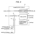
- Fig. 3 shows a second embodiment.
- this embodiment relates to the electrical control unit for an automobile started by two or more wake-up signals including the ignition switch signal like the first embodiment
- Switch 15 is installed on the VB line in front of the input terminal of regulator 12 as a part of power supply circuit 10. Concretely, a MOS transistor etc. can be used as the switch.
- Ignition switch signal IGN and wake-up signals WU1 to WU are input to OR circuit 14 like the first embodiment. If the switch 15 is composed so that it may turn on for instance when the output of this OR circuit 14 is only at a High level, switch 15 is turned on and voltage VB is input to regulator 12 when either one of two or more wake-up signals becomes High level.
- Fig. 4 shows an electrical control unit for an automobile according to a third embodiment to which the wake-up method is applied.
- Electrical control unit 1 is composed of power supply circuit 10 having the composition of the first or second embodiment, microcomputer 30, input circuit 40 which preprocesses the input signal from the sensor and the switch, and driver circuit 50 which drives the actuator.
- Fig. 4 details of this embodiment in which the sensor for the engine control is activated between the release of the door lock by a driver and the turn-on of the ignition switch will be explained.
- the door lock release signal is transmitted to the automobile by pushing the button of the ignition key.
- the signal is sent to electrical control unit 3 for keyless entry through antenna 3A of Fig.4.
- Electrical control unit 3 for keyless entry releases the door lock, and transmits wake-up signal WU to electrical control unit 1 through serial communications line 25 such as a CAN.
- serial communications line 25 such as a CAN.
- ignition switch IGN is still at the off-state.
- the power supply is started with wake-up signal WU, and supplied to microcomputer 30.
- Microcomputer 30 begins the normal operation through power-on reset.
- Microcomputer 30 turns on powertrain relay 4 by turning on the MOS transistor of driver circuit 50 after executing the initialization processing, and supplies battery voltage VB_Powertrain to sensors, various engine control equipment and others.
- the electric current flows to heat resistor 5A for airflow measurement and thermosensitivity resistor 5B for the temperature detection of airflow sensor 5, and the airflow measurement with airflow sensor 5 becomes possible.
- microcomputer 30 supplies the electric current to heat resistor 6A of O 2 sensor 6 by turning on another MOS transistor of driver circuit 50, and heats and activates the O 2 sensor.
- the turn-on time of the MOS transistor which supplies the electric current to the heat resistor 6A of O 2 sensor 6 can be increased. Therefore, a secondary effect which is that the peak current can be suppressed and the size of the transistor can be miniaturized is obtained.
- the airflow sensor and the O 2 sensor is activated before the ignition switching-on in this embodiment, it is also possible to supply the electric current to the equipment such as a fuel pump, the heater of a cold start device (CSD), and activate them as well as the sensors.
- electrical control unit 3 for keyless entry transmits the wake-up signal WU to electrical control unit 1 through serial communications line 25 such as the CAN in this embodiment, it is possible to transmit the wake-up signal directly with a special signal conductor without the serial communications line.
- the electrical control unit for the automobile according to a fourth embodiment is shown in Fig.5.
- This embodiment has the feature that at least one of wake-up signals is transmitted from the timer module.
- wake-up signal WUn is output by using timer module 17 built in microcomputer 30. Therefore, it is necessary to supply the power supply to timer module 17 even at the ignition switching-off to keep operating.
- the method of controlling regulator 12 according to inputting two or more wake-up signals which contain the wake-up signal of the timer module from 17 to OR circuit 14 of power supply circuit 10 is as described in the first embodiment.
- Timer module 17 is composed of divider 62, counter 63, wake-up timing setting register 64, comparator 65, latch 66, and buffer 67.
- the clock pulse generated by quartz vibrator 61 and divider 62 is divided into clock pulses with the suitable frequency. This clock pulse divided is counted by counter 63 as a time base.
- Comparator 65 compares the counter values of counter 63 with the value set in wake-up timing setting register 64. The output is changed from a Low to a High or from a High to a Low when these values are matched.
- Latch 66 latches this change and outputs the wake-up signal. This latch output is reset when a reset signal from bus 68 is input to latch 66.
- the predetermined value can be written in wake-up timing setting register 64 from bus 68. Further, the value of counter 63 can be output to bus 68 through buffer 67.
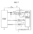
- the electrical control unit for an automobile according to a fifth embodiment is shown in Fig.7.
- the way according to the fourth embodiment is applied to the electrical control unit according to this embodiment. That is, power supply circuit 10 can be started according to wake-up signal WU from the timer module 17 built in microcomputer 30.
- timer module 17 When the period set beforehand elapses before electrical control unit 1 changes in the last sleep state, timer module 17 outputs wake-up signal WU to the power supply circuit. As a result, the power supply is supplied to microcomputer 30, and microcomputer 30 begins the normal operation through the power-on reset. Microcomputer 30 judges the state of the battery from information such as the temperature of the battery and the charging rate, etc., sensed by the battery system 2A after the initialization processing is executed, and transmits a control signal, for example, to cool the battery to the battery system 2A if necessary.
- timer module 17 gives the wake-up signal every certain period, the state of the battery can be monitored periodically even when the ignition switch is turned off, and the battery can be kept in the best state.
- serial communications line 25 such as a CAN
- a CPU of microcomputer 30 reads the counter value of timer module 17, and measures time. For instance, the time after the ignition switch is turned off last time is calculated at the ignition switching-on. The gross weight of the fuel leaked from the injector is estimated in this time. An unburnt element in the exhaust gas at the engine starting can be decreased by correcting fuel injection amount at the engine starting by using this estimate. Further, if timer module 17 is always operated, it is possible to know the elapsed time after the automobile begins running. Therefore, the amount of harmful exhaust gas of the automobile can be suppressed to the level equivalent to the amount immediately after beginning of running for years by estimating the deteriorating with the passage of time degree of various equipment based on the elapsed time and tuning online control parameters.
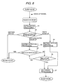
- the control-flow at wake-up in the electrical control units for an automobile according to the third and the fifth embodiments is shown in Fig.8.
- the microcomputer is started by power-on reset when the wake-up signal is input.
- the electrical control unit for an automobile wakes up from sleep mode.
- initialization is executed in step S1
- the wake-up factor is judged in step S2.
- the engine is started when judged that wake-up was done by the ignition switching-on.
- the processing advances to step S3 when judged that the wake-up was done according to the wake-up signal from the electrical control unit for keyless entry.
- the system activation processing which energizes to the sensor, the fuel pump, and the cold start device, etc. is executed as described in the third embodiment.
- step S5 it is confirmed whether the ignition switch turned on in step S5. If it has been turned on, the engine is started, otherwise, the processing advances to step S6. It is judged whether long time has passed since preset time T after the wake-up is done. The processing returns to step S5 again when the elapsed time is less than time T. The processing advances to step S7 when the time more than time T passes, the shutdown processing to stop the operation of the power supply circuit is executed, and the processing shifts to the sleep mode again. The processing advances to step S4 when judged that the wake-up was done according to the wake-up signal from the timer module in step S2, and the control processing of the battery system is executed as described in the fifth embodiment.
- the shutdown processing in step S7 is executed after this processing ends, and the processing shifts to the sleep mode again.
- the electrical control unit is prevented from keeping starting by executing the shutdown processing after the execution of after the state that the ignition switch does not turn on after the execution of the system activation processing ends continues during the predetermined time of period or after the battery system control processing ends, and shifting to the sleep mode again.
- the amount of the electrical discharge of the battery at the ignition switching-off can be decreased.
- the electrical control unit for an automobile according to a sixth embodiment is shown in Fig. 9.
- the electrical control unit of this embodiment has the feature that a function necessary to execute the predetermined processing by starting according to a wake-up signal other than the ignition switch even when the ignition switch is cut off is made as a single-chip of a power supply IC.
- Power supply IC 10A in this embodiment is composed of the following components.
- Regulator 12 which generates voltage to operate microcomputer 30 by inputting an ignition switch signal or a wake-up signal
- regulator 11A for a backup power supply which supplies the power supply to the circuit such as microcomputer 30 and power supply IC 10A in which power supply is always necessary at sleep
- OR circuit 14 to activate regulator 12 according to either one of the ignition switch signal or a plurality of wake-up signals
- Wake-up factor determining register 19 which distinguishes whether regulator 12 is activated by either one of the ignition switch or two or more wake-up signals
- communication driver 18 which transmits and receives a communications signal to and from outside electrical control unit by serial communications line 25 such as a CAN
- circuit 16 which latches the wake-up signal transmitted from an outside electrical control unit through serial communications line 25 such as a CAN
- reset signal generating circuit 13 which generates the reset signal to microcomputer 30, watchdog timer 21 to prevent the runaway of active program running in microcomputer 30, and serial communications module 20 which communicates in serial with microcomputer 30.
- the operation of power supply IC 10A and microcomputer 30 composed like this will be explained in detail.
- the power supply from the regulator 11A for backup power supply is supplied to communication driver 18, latch 16, wake-up factor determining register 19, OR circuit 14, and timer module 17 built in microcomputer 30 at the sleep in this embodiment.
- the wake-up signal transmitted from an outside electrical control unit through serial communications line 25 such as a CAN is a pulse signal of which pulse width is about 100 ⁇ s, regulator 12 cannot be started by this pulse width. Therefore, latch 16 which memorizes the level change in Rx signal from communication driver 18 is needed.
- Rx signal from communication driver 18 is input to set terminal (S) of latch 16.
- the output of latch 16 and the ignition switch signal IGN is input not only to OR circuit 14, but also wake-up factor determining register 19.
- the content of wake-up factor determining register 19 is transmitted to microcomputer 30 via serial communications module 20 according to the demand of microcomputer 30 after the wake-up. As a result, microcomputer 30 can judge the wake-up factor which corresponds to step S2 of Fig.8.
- SPI Serial Peripheral Interface
- Reset signal generating circuit 13 outputs the power-on reset signal to microcomputer 30 when regulator 12 starts. Further, it outputs the reset signal to microcomputer 30 also when the program being executed in microcomputer 30 runs away, the WDT signal which clears watchdog timer 21 is not supplied from microcomputer 30, and thus the timer of watchdog timer 21 overflows.
- microcomputer 30 carries out the shutdown processing which corresponds to step S7 of Fig.8.
- Microcomputer 30 transmits the command by which latch 16 is reset to power supply IC 10A by the SPI communication.
- the reset signal is sent to reset terminal (R) of the latch by serial communications module 20, and the output of the latch is shifted to a Low state.
- Microcomputer 30 voluntarily makes the power control signal low, stops the operation of regulator 12 after the whole shutdown processing including the data backup to the RAM ends. As a result, the electrical control unit shuts down.
- the function to control the power supply of the electrical control unit is integrated into one IC according to this embodiment, it becomes possible to decrease the number of parts of the electrical control unit and improve the reliability. Especially, as described so far, it is actually important to have built OR circuit 14 and wake-up factor determining register 19 into power supply IC so that the microcomputer can be started by any one of two or more wake-up signals.
- the determination of the wake-up factor may be achieved by inputting each wake-up signal directly to a general-purpose port of the microcomputer, and observing the state of those ports by the software after the microcomputer starts.
- the number of use ports of the microcomputer increases according to this method. Further, it is necessary to provide a tri-state buffer etc.
- the electrical control unit for an automobile according to a seventh embodiment is shown in Fig.10.
- a timer module is also integrated in the power supply IC according to the sixth embodiment.
- the power supply IC will be explained.
- the clock pulse generated from quartz vibrator 61 and oscillator 60 is input to timer module 17 built in the power supply IC of this embodiment.
- the composition of timer module 17 is as shown in Fig. 6. Because the counter value of timer module 17 is transmitted to microcomputer 30 by the SPI communication, microcomputer 30 can control as mentioned above by using this value. Further, when the shutdown processing is performed, microcomputer 30 can write the value corresponding to time when the wake-up is done next to wake-up timing setting register 64, and can reset latch 66 which outputs the wake-up signal for timer module 17 via the SPI communication.
- the current consumption of the timer module has the tendency which increases by the influence such as the leakage on the surrounding module.
- the timer module is built into the power supply IC of which the scale of logic is far small compared with the microcomputer, the current consumption can be greatly decreased compared with the case where this is built into the microcomputer. This is effective to decrease further the standby electric current in the electrical control unit at the sleep. According to this embodiment, it becomes possible to control the battery etc. by waking up periodically as explained in the fifth embodiment even when the microcomputer without the built-in timer module is used.
- the electrical control unit for an automobile according to an eighth embodiment is shown in Fig. 11.
- the electrical control unit for an automobile of this embodiment has the feature in having provided with the power supply such as BR system lithium electric cell in the device.
- electric cell 70 can supply the power supply to timer module 17 of power supply IC 10A in this embodiment.
- power supply switch means 71 is installed in power supply IC 10A, and electric cell 70 is composed so as not to supply the power supply when the battery is connected as shown in Fig. 11.
- the power_supply of timer module 17 and oscillator 60 is connected to VDDL_BU generated by the regulator 11A for backup power supply through power supply switch means 71.
- the output of latch 66 and buffer 67 of timer module 17 (Referring to Fig. 6) becomes possible by inputting VDDL_BU to EN terminal of timer module 17.
- the power supply of timer module 17 and oscillator 60 is connected to electric cell 70.
- the input voltage of EN terminal of timer module 17 becomes 0 V, and the output of latch 66 and buffer 67 enters the state of the high impedance.
- FIG. 12 An embodiment of power supply switch means 71 is shown concretely in Fig. 12.
- PMOS transistor 72 When the battery is connected, PMOS transistor 72 is turned off, and only VDDL_BU is supplied to the timer module if the battery potential difference to VDDL_BU is below the threshold voltage of PMOS transistor 72.
- PMOS transistor 72 turns on, and the electric current is supplied to the timer module by the electric cell because VDDL_BU becomes 0 V.
- Diode 73 is provided so that the electric current from the electric cell should not flow into the VDDL_BU line at this time.
- the timer module can keep being operated with a built-in electric cell according to this embodiment even when the power supply is not supplied from the outside, for example, by exchanging the battery. As a result, accurately measuring the elapsed time after the automobile begins running and the control cycle when controlling by periodic wake-up becomes possible.
- the electrical discharge of the electric cell can be controlled when the battery is connected, that is, it is in a normal operation by having installed the power supply switch means, it is possible to extend the life time of the battery to the same degree of the period as the life cycle of the automobile.
- the consumption of the battery can be decreased by making the output of the timer module to be a state of high impedance to prevent the electric current from flowing into the circuit which the power supply is not supplied, or installing the diode in the power supply switch means to prevent the electric current from flowing into the VDDL_BU line even when the electric cell is used.
- the electrical control unit for an automobile which achieves the function that the predetermined processing can be executed by the low standby electric current can be provided by starting according to various wake-up signals even when the ignition switch is cut off according to each embodiment. Further, the electrical control unit for a suitable automobile for executing the predetermined processing by starting according to the wake-up signal for not only the low standby electric current but also the function side can be provided.
- an electrical control unit for an automobile which is started by wake-up signals other than the ignition switch when the ignition switch is cut off, only the backup electric current is supplied to the microcomputer at the sleep, and the regulator which supplies the power supply to the CPU core is activated according to the wake-up signal to start the microcomputer. Accordingly, the standby electric current need not keep being supplied to CPU core of the microcomputer at the sleep like the conventional wake-up method to input the wake-up signal to the interrupt terminal of microcomputer.
- the regulator which supplies the electric current to the CPU core need not be operated to supply this standby electric current, the standby electric current can be greatly decreased.
- the electrical control unit for an automobile which uses such a wake-up method has a small standby current, and can decrease the harmful exhaust gas at the engine starting by activating the sensor etc. before the ignition switching-on by starting the electrical control unit for an automobile according to the wake-up signal transmitted from the electrical control unit for keyless entry. Further, a periodic battery control at the ignition switching-off can be done in a hybrid automobile etc. by starting the electrical control unit for an automobile by the wake-up signal transmitted from the timer module.
- the electrical control unit is prevented from keeping starting by executing the shutdown processing after the execution of after the state that the ignition switch does not turn on after the execution of the system activation processing ends continues during the predetermined time of period or after the battery system control processing ends, and shifting to the sleep mode again. As a result, the amount of the electrical discharge of the battery at the ignition switching-off can be decreased.
- a CPU of microcomputer 30 reads the counter value of timer module 17, and measures time. For instance, the time after the ignition switch is turned off last time is calculated at the ignition switching-on. The gross weight of the fuel leaked from the injector is estimated in this time. An unburnt element in the exhaust gas at the engine starting can be decreased by correcting fuel injection amount at the engine starting by using this estimate. Further, if timer module 17 is always operated, it is possible to know the elapsed time after the automobile begins running. Therefore, the amount of harmful exhaust gas of the automobile can be suppressed to the level equivalent to the amount immediately after beginning of running for years by estimating the deteriorating with the passage of time degree of various equipment based on the elapsed time and tuning online control parameters.
- the function to control the power supply of the electrical control unit is integrated into one IC according to this embodiment, it becomes possible to decrease the number of parts of the electrical control unit and improve the reliability. Especially, as described so far, it is actually important to have built OR circuit 14 and wake-up factor determining register 19 into power supply IC so that the microcomputer can be started by any one of two or more wake-up signals.
- the current consumption of the timer module has the tendency which increases by the influence such as the leakage on the surrounding module.
- the timer module is built into the power supply IC of which the scale of logic is far small compared with the microcomputer, the current consumption can be greatly decreased compared with the case where this is built into the microcomputer. This is effective to decrease further the standby electric current in the electrical control unit at the sleep. According to this embodiment, it becomes possible to control the battery etc. by waking up periodically as explained in the fifth embodiment even when the microcomputer without the built-in timer module is used.
- the timer module can keep being operated with a built-in electric cell according to this embodiment even when the power supply is not supplied from the outside, for example, by exchanging the battery. As a result, accurately measuring the elapsed time after the automobile begins running and the control cycle when controlling by periodic wake-up becomes possible.
- the electrical discharge of the electric cell can be controlled when the battery is connected, that is, it is in a normal operation by having installed the power supply switch means, it is possible to extend the life time of the battery to the same degree of the period as the life cycle of the automobile.
- the consumption of the battery can be decreased by making the output of the timer module to be a state of high impedance to prevent the electric current from flowing into the circuit which the power supply is not supplied, or installing the diode in the power supply switch means to prevent the electric current from flowing into the VDDL_BU line even when the electric cell is used.
- an electrical control unit for an automobile of which standby current is smaller can be provided.
Abstract
Description
- The present invention relates to an electrical control unit for an automobile. Especially, the present invention relates to an electrical control unit for an automobile started by a wake-up signal other than the ignition switch signal, even when the ignition switch is cut off.
- Microcomputer is indicated when the wake-up starting circuit generates the wake-up trigger signal by inputting external switch, and this signal is input to the interrupt terminal of microcomputer and the composition that wake-up is done is disclosed in Japanese Patent Application Laid-Open No. 2002-108519.
- The conventional electrical control unit needs to keep supplying the electric current from the battery when the ignition switch is cut off, because it cannot start according to a wake-up signal other than an ignition switch signal.
However, when the electric current consumption at this sleep, that is, the standby electric current is large, the amount of the electrical discharge from the battery increases when the automobile is not driven for a long term. As a result, the possibility that the engine cannot be started may occur. It is required to decrease the standby electric current of an individual electrical control unit as much as possible because various equipment such as a lot of electrical control units are installed in the present automobile. - In the conventional wake-up method in which the wake-up signal is input to an interrupt terminal of the microcomputer, it is required to keep supplying the standby electric current to a CPU core of the microcomputer at the sleep. The standby electric current of the microcomputer is small in the conventional electrical control unit of the body system in which the circuit scale of the microcomputer is comparatively small. However, the microcomputer with high performance and multi-function is installed in the electrical control unit which controls the powertrain such as an engine, etc. Therefore, the leakage current is larger because the logic scale is larger than that of the microcomputer for the body system control. As a result, there is a problem that the standby electric current of the microcomputer, and thus the standby electric current of the electrical control unit increases. Further, because it is necessary to operate the same power supply circuit as the power supply circuit which supplies the electric current to the CPU core at the normal operation in order to supply the standby electric current to the CPU core, the standby electric current will be become larger.
- For instance, the special description on how to wake up the electrical control unit cannot be found in USP 5,894,832.
- Further, it is required to keep supplying the electric current to the electrical control unit for which the regular wake-up is necessary, when the ignition switch is cut off. In such a case, the wake-up method by which the wake-up signal is input to the interrupt terminal of the microcomputer is undesirable as described above. Further, the consumption current of the timer module installed in the microcomputer has the tendency that increases by the influence such as the leak to the modules in the surrounding, and it relates to the increase in the standby electric current, although the method by which the wake-up signal is output by using the timer module installed in the microcomputer is thought.
- The present invention is achieved in consideration of the above-mentioned problems. An object of the present invention is to provide an electrical control unit for an automobile of which the standby electric current is smaller.
- To solve said problems, the present invention adopts an electrical control unit for an automobile comprised of a microcomputer, an input circuit, a driver circuit and/or a power supply circuit. Said microcomputer can be started by a wake-up signal other than the ignition switch signal. Concretely, said microcomputer can be started by shifting said power supply circuit from an inert state to an active state to generate the voltage by which said microcomputer is operated by a wake-up signal from the circuit other than the ignition switch, even when the ignition switch of said automobile is cut off, and the predetermined processing is executed by the microcomputer.
- According to the above-mentioned method, it is not required to keep supplying the standby electric current to the CPU core of the microcomputer like the wake-up method in which the wake-up signal is input to the interrupt terminal of the microcomputer, since the power supply circuit (regulator) is activated by the wake-up signal by supplying only the backup power supply at the sleep. Further, the regulator which supplies the electric current to the CPU core has not to supply the standby electric current. Therefore, the standby electric current can be greatly decreased.
-
- Fig. 1 is an explanatory drawing showing a wake-up method of an electrical control unit for an automobile.
- Fig. 2 is a block diagram of a power supply circuit of the electrical control unit for an automobile according to a first embodiment.
- Fig. 3 is a block diagram of a power supply circuit of the electrical control unit for an automobile according to a second embodiment.
- Fig. 4 is an electrical control unit for an automobile according to a third embodiment in which a sensor is controlled by using the wake-up method.
- Fig. 5 is a block diagram of a power supply circuit and a microcomputer of the electrical control unit for an automobile according to a fourth embodiment.
- Fig. 6 is a block diagram of a timer module circuit.
- Fig. 7 is an electrical control unit for an automobile according to a fifth embodiment in which the battery system is controlled by using the wake-up method.
- Fig. 8 is a control flow chart of the wake-up in an electrical control unit for an automobile according to the third embodiment and the fifth embodiment.
- Fig. 9 is a block diagram of an electrical control unit for an automobile according to a sixth embodiment, which includes the detailed circuit block diagram of the power supply IC.
- Fig. 10 is a block diagram of an electrical control unit for an automobile according to a seventh embodiment, which includes the detailed circuit block diagram of the power supply IC.
- Fig. 11 is a block diagram illustrating a power supply switch means installed in the power supply IC in an electrical control unit for an automobile according to a eighth embodiment.
- Fig. 12 is a circuit diagram of the power supply switch means.
-
- The inventors studied the electrical control unit for an automobile in various ways.
- There are some electrical control units for an automobile that it is necessary to execute the predetermined processing by starting it by some kind or another wake-up signal other than the ignition switch even when the ignition switch is cut off. For instance, when the ignition switch is cut off and the engine has stopped, it is required to operate the external switch circuit and the microcomputer by using the input from the external switch as for the electrical control unit which controls the equipment of the body system like the power window and the door module, etc.
- In the conventional configuration, the microcomputer is waked up by providing a wake-up trigger signal from a wake-up starting circuit, and inputting this signal to the interrupt terminal of the microcomputer when the external switch signal is input. Further, in another conventional example (USP5894832), the electrical control unit performs the activation processing of a cold start device (CSD) by energizing the heater of the equipment before the ignition switch is connected.
- Further, it is known that in the electrical control unit in a hybrid automobile, etc. in which the drive force is generated by using the motor together with the engine, the wake-up is regularly carried out, the temperature of a battery and charging rates is monitored and these devices are controlled if necessary even when the ignition switch is cut off.
- The inventors have achieved the following invention.
An electrical control unit for an automobile can comprise a microcomputer, an input circuit, a driver circuit and/or a power supply circuit. Said microcomputer can be started by a wake-up signal other than the ignition switch signal. Said microcomputer can be started by shifting said power supply circuit from an inert state to an active state to generate the voltage by which said microcomputer is operated by a wake-up signal from the circuit other than the ignition switch even when the ignition switch of said automobile is cut off, and the predetermined processing is executed by the microcomputer. - Said wake-up signal can be a signal transmitted at least from either the electrical control unit for the keyless entry, or an electrical control unit for the door lock management by which it can be perceived whether the car owner gets on or have gotten on the automobile.
The electrical control unit for an automobile can start said microcomputer by activating said power supply circuit according to this wake-up signal, and can begin to turn on any one of an airflow sensor, an O2 sensor, a fuel pump or various heater devices in advance of the connection of the ignition switch. - Further, another form of said wake-up signal can be a signal output by the timer module which is built into the electrical control unit for the automobile or an electrical control unit other than one concerned, and may be composed of ai least a counter, a wake-up timing setting register and/or a comparator, when the value of said counter reaches the value set in said wake-up timing setting register beforehand.
The electrical control unit for an automobile can start said microcomputer by activating said power supply circuit according to this wake-up signal to monitor the states of various equipment of the automobile concerned or control the equipment concerned if necessary. - Said microcomputer can make said power supply circuit inert after the execution of the processing is completed, or after the state that the ignition switch is not connected continues during the predetermined time after the completion of the execution of said predetermined processing, and shuts down the electrical control unit for the automobile concerned again.
- Further, the electrical control unit for the automobile can calculate the period elapsed after the ignition switch is cut off at the time when the ignition switch is connected by using the count value of said timer module to estimate the amount of the fuel leakage from the injector during the period concerned. Further, by using this, it can correct fuel consumption at the engine start or estimate the level of deteriorating with the passage of time of various equipment of the automobile concerned to control the automobile.
- Still further, an electrical control unit for the automobile can comprise a microcomputer, an input circuit, a driver circuit, and a power supply circuit, and can be started by a wake-up signal from the circuit other than the ignition switch even when the ignition switch of said automobile is cut off.
Further, said power supply circuit can be a semiconductor IC that can integrate the following components, a first regulator which can generate the voltage to operate said microcomputer by inputting said ignition switch signal or said wake-up signal, a second regulator which can operate even when said ignition switch is cut off, an OR circuit that can activate said first regulator by using either the ignition switch signal or one of said plural wake-up signals, a start factor determining means which can distinguish whether said first regulator is activated by which signal of the ignition switch signal and/or one of plural wake-up signals, a communication driver which can transmit and receive the communication signal with an outside electrical control unit through a communications line, a latch circuit that can latch the wake-up signals transmitted from the outside electrical control unit through said communications line, a reset circuit which can generate a reset signal to said microcomputer, a watchdog timer that can prevent the runaway of the active program in said microcomputer, and a serial communications module which can communicate serially with said microcomputer.
The start factor distinguished by the start factor determining means of said semiconductor IC can be transmitted to said microcomputer through said serial communications module. - In the electrical control unit for an automobile according to the invention, said semiconductor IC can include a counter, a wake-up timing setting register, a comparator, and/or a timer module which outputs the wake-up signal when the value of said counter reaches the value set in said wake-up timing setting register beforehand is integrated therewith.
Further, said microcomputer can set the value of said wake-up timing setting register of said timer module through the serial communications module of said semiconductor IC, or said timer module can transmit the counter value at that time to said microcomputer. - The electrical control unit for the automobile provides inside with the power supply to operate at least said timer module for the period when the power supply is not supplied from the outside. Said semiconductor IC has the power supply switch means. Said switch means supplies a current to said timer module either from said outside power supply for the period when the power supply is supplied from the outside to said electrical control unit for the automobile, or from the power supply provided in said electrical control unit for the automobile for the period when the power supply is not supplied from the outside.
Further, in the electrical control unit for an automobile, the power supply such as lithium electric cell can be provided in the electrical control unit to operate said timer module at least even when the power supply is not supplied from the outside to the electrical control unit for an automobile. Further, there is a power supply switch means to supply the electric current to the timer module. It supplies the current from the power supply provided in the electrical control unit for an automobile, when the power supply is not supplied from the outside, and only from the external power supply when the power supply is supplied from the outside. The electrical control unit for an automobile has the feature that this power supply switch means can be integrated into the semiconductor IC having the timer module inside. - Hereinafter, the electrical control unit for an automobile will be explained with reference to the drawings.
- Fig.1 is an explanatory drawing concerning a wake-up method of the electrical control unit for an automobile, and shows only a microcomputer and a power supply circuit necessary for explaining the wake-up method.
Power supply circuit 10 is composed of backuppower supply circuit 11,regulator 12, and resetsignal generating circuit 13. Thispower supply circuit 10 generates a voltage for operatingmicrocomputer 30 from the voltages VB, VB_BU of the battery. Backuppower supply circuit 11 is a constant voltage source which composed of a regulator, or a resistor and a Zener diode, and which supplies the electric power to an electronic circuit such as a RAM built inmicrocomputer 30 necessary always to supply the electric power regardless of the on/off of the ignition switch by regulating VB_BU connected to the battery.Regulator 12 regulates VB, and supplies the electric power to the entire electrical parts installed in the electrical control unit such as a microcomputer. - The wake-up method is explained by using Fig.1. Only backup
power supply circuit 11 works, and supplies VDDL_BU tomicrocomputer 30 at the switching-off of the ignition, that is, at the sleep.Microcomputer 30 is in an operation mode in which only the data of the built-in RAM is maintained. At this time, VB is supplied to the input terminal thoughregulator 12 is not operated. By activatingregulator 12 according to wake-up signal WU at the wake-up time, the supply of the power source VDDH for the I/O circuit in the peripheral module and the power supply VDDL for the CPU core tomicrocomputer 30 is started. After these voltages are generated, resetsignal generating circuit 13 makes the reset signal low for the predetermined period, and makesmicrocomputer 30 power-on reset.Microcomputer 30 shifts to the normal operation mode by the power-on reset, and the electrical control unit starts. - Thus, the standby electric current need not keep being supplied to the CPU core of the microcomputer at the sleep like the conventional wake-up method to input the wake-up signal to the interrupt terminal of the microcomputer, because the wake-up method by power-on reset supplies only the backup power supply at the sleep, and activates
regulator 12 for the first time by the wake-up signal. In addition, it is not necessary to operateregulator 12 which supplies the electric current to the CPU core in order to supply the standby electric current. As a result, the standby electric current can be greatly decreased. - Fig. 2 shows a first embodiment of the electrical control unit for an automobile, which is started by two or more wake-up signals including a signal from the ignition switch. An Enable terminal which activates or inactivates
regulator 12 from the outside is provided inregulator 12 ofpower supply circuit 10. For instance, when this Enable terminal is at a High level,regulator 12 supplies the electric current to the microcomputer, and it stops the operation so that the output voltage may become 0V when at a Low level. In addition, ignition switch signal IGN and wake-up signals WU1 to WU are input to ORcircuit 14, and the output of ORcircuit 14 is input to said Enable terminal.
Thus, when either one of two or more wake-up signals becomes High level, the output of the OR circuit changes from a Low level into a High level, andregulator 12 can be started. - Fig. 3 shows a second embodiment. Although this embodiment relates to the electrical control unit for an automobile started by two or more wake-up signals including the ignition switch signal like the first embodiment,
Switch 15 is installed on the VB line in front of the input terminal ofregulator 12 as a part ofpower supply circuit 10. Concretely, a MOS transistor etc. can be used as the switch. Ignition switch signal IGN and wake-up signals WU1 to WU are input to ORcircuit 14 like the first embodiment.
If theswitch 15 is composed so that it may turn on for instance when the output of this ORcircuit 14 is only at a High level,switch 15 is turned on and voltage VB is input toregulator 12 when either one of two or more wake-up signals becomes High level. As a result, power supplies VDDH and VDDL can be supplied to the microcomputer. It is possible to control whether to supply the power supply to the microcomputer by turning on/offswitch 15 according to this embodiment, even if the function for activating or inactivatingregulator 12 from the outside is not provided in the regulator. - Fig. 4 shows an electrical control unit for an automobile according to a third embodiment to which the wake-up method is applied.
Electrical control unit 1 is composed ofpower supply circuit 10 having the composition of the first or second embodiment,microcomputer 30,input circuit 40 which preprocesses the input signal from the sensor and the switch, anddriver circuit 50 which drives the actuator. - Referring to Fig. 4, details of this embodiment in which the sensor for the engine control is activated between the release of the door lock by a driver and the turn-on of the ignition switch will be explained. When the driver gets on the automobile, the door lock release signal is transmitted to the automobile by pushing the button of the ignition key. When this signal is supplied by an electric wave, the signal is sent to
electrical control unit 3 for keyless entry throughantenna 3A of Fig.4.Electrical control unit 3 for keyless entry releases the door lock, and transmits wake-up signal WU toelectrical control unit 1 throughserial communications line 25 such as a CAN. At this point, ignition switch IGN is still at the off-state. The power supply is started with wake-up signal WU, and supplied tomicrocomputer 30.Microcomputer 30 begins the normal operation through power-on reset.Microcomputer 30 turns onpowertrain relay 4 by turning on the MOS transistor ofdriver circuit 50 after executing the initialization processing, and supplies battery voltage VB_Powertrain to sensors, various engine control equipment and others. As a result, the electric current flows to heatresistor 5A for airflow measurement andthermosensitivity resistor 5B for the temperature detection ofairflow sensor 5, and the airflow measurement withairflow sensor 5 becomes possible. Further,microcomputer 30 supplies the electric current to heatresistor 6A of O2 sensor 6 by turning on another MOS transistor ofdriver circuit 50, and heats and activates the O2 sensor. - It will be thought that these sensors have been activated enough by the time the driver turns on the ignition switch and the engine is started, because time from the reception of the door lock release signal by
electrical control unit 3 for keyless entry to the activation ofairflow sensor 5 and O2 sensor 6 is about several seconds. Therefore, the amount of harmful exhaust gas at the engine starting can be reduced.
Although it is difficult to put the method of decreasing the harmful exhaust gas at the engine starting by activating the sensors, etc. before the ignition switch is turned on into practical use in case of an electrical control unit with a large standby electric current by the conventional wake-up method, it becomes possible for the first time by usingelectrical control unit 1 of which the standby electric current is very small like this embodiment. In addition, because the electric current can be supplied into the load before the ignition switching-on, the turn-on time of the MOS transistor which supplies the electric current to theheat resistor 6A of O2 sensor 6 can be increased. Therefore, a secondary effect which is that the peak current can be suppressed and the size of the transistor can be miniaturized is obtained. - Although the airflow sensor and the O2 sensor is activated before the ignition switching-on in this embodiment, it is also possible to supply the electric current to the equipment such as a fuel pump, the heater of a cold start device (CSD), and activate them as well as the sensors. Further, although
electrical control unit 3 for keyless entry transmits the wake-up signal WU toelectrical control unit 1 throughserial communications line 25 such as the CAN in this embodiment, it is possible to transmit the wake-up signal directly with a special signal conductor without the serial communications line. In addition, it is possible to installpowertrain relay 4 on the upstream side of the VB line so that the battery voltage may not supplied from the VB line at the ignition switching-off, although there are two input terminals for the battery voltage ofelectrical control unit 1 and each is always connected to battery 2 regardless of the on/off of the ignition switch in this embodiment. In this case, it is necessary to supply the battery voltage to the input terminal ofregulator 12 ofpower supply circuit 10 by separating VB_BU at the inside of theelectrical control unit 1. - The electrical control unit for the automobile according to a fourth embodiment is shown in Fig.5.
This embodiment has the feature that at least one of wake-up signals is transmitted from the timer module. In this embodiment, wake-up signal WUn is output by usingtimer module 17 built inmicrocomputer 30. Therefore, it is necessary to supply the power supply totimer module 17 even at the ignition switching-off to keep operating. The method of controllingregulator 12 according to inputting two or more wake-up signals which contain the wake-up signal of the timer module from 17 to ORcircuit 14 ofpower supply circuit 10 is as described in the first embodiment. - The configuration of
timer module 17 will be explained by using Fig.6.Timer module 17 is composed ofdivider 62, counter 63, wake-uptiming setting register 64,comparator 65,latch 66, andbuffer 67. The clock pulse generated byquartz vibrator 61 anddivider 62 is divided into clock pulses with the suitable frequency. This clock pulse divided is counted by counter 63 as a time base.Comparator 65 compares the counter values ofcounter 63 with the value set in wake-uptiming setting register 64. The output is changed from a Low to a High or from a High to a Low when these values are matched.Latch 66 latches this change and outputs the wake-up signal. This latch output is reset when a reset signal frombus 68 is input to latch 66. The predetermined value can be written in wake-uptiming setting register 64 frombus 68. Further, the value ofcounter 63 can be output tobus 68 throughbuffer 67. - The electrical control unit for an automobile according to a fifth embodiment is shown in Fig.7. The way according to the fourth embodiment is applied to the electrical control unit according to this embodiment. That is,
power supply circuit 10 can be started according to wake-up signal WU from thetimer module 17 built inmicrocomputer 30. - Details of this embodiment will be explained by using Fig.7. When the period set beforehand elapses before
electrical control unit 1 changes in the last sleep state,timer module 17 outputs wake-up signal WU to the power supply circuit. As a result, the power supply is supplied tomicrocomputer 30, andmicrocomputer 30 begins the normal operation through the power-on reset.Microcomputer 30 judges the state of the battery from information such as the temperature of the battery and the charging rate, etc., sensed by thebattery system 2A after the initialization processing is executed, and transmits a control signal, for example, to cool the battery to thebattery system 2A if necessary. Becausetimer module 17 gives the wake-up signal every certain period, the state of the battery can be monitored periodically even when the ignition switch is turned off, and the battery can be kept in the best state.
In this embodiment, it is possible to wake upelectrical control unit 1 periodically even if the timer module is not mounted onelectrical control unit 1, but on thebattery system 2A side, because the wake-up signal is received periodically frombattery system 2A throughserial communications line 25 such as a CAN, andpower supply circuit 10 is started. In any case, a periodic battery control at the ignition switching-off can be done in a hybrid automobile etc. with the standby electric current of the electrical control unit kept small according to this embodiment. - Further, various controls become possible in this embodiment because a CPU of
microcomputer 30 reads the counter value oftimer module 17, and measures time. For instance, the time after the ignition switch is turned off last time is calculated at the ignition switching-on. The gross weight of the fuel leaked from the injector is estimated in this time. An unburnt element in the exhaust gas at the engine starting can be decreased by correcting fuel injection amount at the engine starting by using this estimate. Further, iftimer module 17 is always operated, it is possible to know the elapsed time after the automobile begins running. Therefore, the amount of harmful exhaust gas of the automobile can be suppressed to the level equivalent to the amount immediately after beginning of running for years by estimating the deteriorating with the passage of time degree of various equipment based on the elapsed time and tuning online control parameters. - The control-flow at wake-up in the electrical control units for an automobile according to the third and the fifth embodiments is shown in Fig.8. The microcomputer is started by power-on reset when the wake-up signal is input. As a result, the electrical control unit for an automobile wakes up from sleep mode.
First of all, initialization is executed in step S1, then the wake-up factor is judged in step S2. The engine is started when judged that wake-up was done by the ignition switching-on. The processing advances to step S3 when judged that the wake-up was done according to the wake-up signal from the electrical control unit for keyless entry. The system activation processing which energizes to the sensor, the fuel pump, and the cold start device, etc. is executed as described in the third embodiment. Next, it is confirmed whether the ignition switch turned on in step S5. If it has been turned on, the engine is started, otherwise, the processing advances to step S6. It is judged whether long time has passed since preset time T after the wake-up is done. The processing returns to step S5 again when the elapsed time is less than time T. The processing advances to step S7 when the time more than time T passes, the shutdown processing to stop the operation of the power supply circuit is executed, and the processing shifts to the sleep mode again. The processing advances to step S4 when judged that the wake-up was done according to the wake-up signal from the timer module in step S2, and the control processing of the battery system is executed as described in the fifth embodiment. The shutdown processing in step S7 is executed after this processing ends, and the processing shifts to the sleep mode again. Thus, the electrical control unit is prevented from keeping starting by executing the shutdown processing after the execution of after the state that the ignition switch does not turn on after the execution of the system activation processing ends continues during the predetermined time of period or after the battery system control processing ends, and shifting to the sleep mode again. As a result, the amount of the electrical discharge of the battery at the ignition switching-off can be decreased. - The electrical control unit for an automobile according to a sixth embodiment is shown in Fig. 9. The electrical control unit of this embodiment has the feature that a function necessary to execute the predetermined processing by starting according to a wake-up signal other than the ignition switch even when the ignition switch is cut off is made as a single-chip of a power supply IC.
Power supply IC 10A in this embodiment is composed of the following components.Regulator 12 which generates voltage to operatemicrocomputer 30 by inputting an ignition switch signal or a wake-up signal,regulator 11A for a backup power supply which supplies the power supply to the circuit such asmicrocomputer 30 andpower supply IC 10A in which power supply is always necessary at sleep, ORcircuit 14 to activateregulator 12 according to either one of the ignition switch signal or a plurality of wake-up signals, Wake-upfactor determining register 19 which distinguishes whetherregulator 12 is activated by either one of the ignition switch or two or more wake-up signals,communication driver 18 which transmits and receives a communications signal to and from outside electrical control unit byserial communications line 25 such as a CAN,circuit 16 which latches the wake-up signal transmitted from an outside electrical control unit throughserial communications line 25 such as a CAN, resetsignal generating circuit 13 which generates the reset signal tomicrocomputer 30,watchdog timer 21 to prevent the runaway of active program running inmicrocomputer 30, andserial communications module 20 which communicates in serial withmicrocomputer 30. - The operation of
power supply IC 10A andmicrocomputer 30 composed like this will be explained in detail. The power supply from theregulator 11A for backup power supply is supplied tocommunication driver 18,latch 16, wake-upfactor determining register 19, ORcircuit 14, andtimer module 17 built inmicrocomputer 30 at the sleep in this embodiment. - The outputs of ignition switch IGN and latch 16, the output from the
timer module 17 built inmicrocomputer 30,and the power control signal from a general-purpose port are input to ORcircuit 14, and the output of ORcircuit 14 is input to the Enable terminal ofregulator 12. If either one of the signals input to above-mentioned ORcircuit 14 is at a High state,regulator 12 supplies voltages VDDH and VDDL tomicrocomputer 30.Microcomputer 30 makes the power control signal high by the initialization processing after the start. As a result, two of input signals to ORcircuit 14 becomes high, and the reliability of the operation ofregulator 12 can be improved. - Because the wake-up signal transmitted from an outside electrical control unit through
serial communications line 25 such as a CAN is a pulse signal of which pulse width is about 100 µs,regulator 12 cannot be started by this pulse width. Therefore, latch 16 which memorizes the level change in Rx signal fromcommunication driver 18 is needed. Rx signal fromcommunication driver 18 is input to set terminal (S) oflatch 16. The output oflatch 16 and the ignition switch signal IGN is input not only to ORcircuit 14, but also wake-upfactor determining register 19. The content of wake-upfactor determining register 19 is transmitted tomicrocomputer 30 viaserial communications module 20 according to the demand ofmicrocomputer 30 after the wake-up. As a result,microcomputer 30 can judge the wake-up factor which corresponds to step S2 of Fig.8. Although the SPI (Serial Peripheral Interface) protocol is used as the communication betweenmicrocomputer 30 andpower supply IC 10A in this embodiment, it is possible to use another serial communications method. - Reset
signal generating circuit 13 outputs the power-on reset signal tomicrocomputer 30 whenregulator 12 starts. Further, it outputs the reset signal tomicrocomputer 30 also when the program being executed inmicrocomputer 30 runs away, the WDT signal which clearswatchdog timer 21 is not supplied frommicrocomputer 30, and thus the timer ofwatchdog timer 21 overflows. - The processing at the turn-off of the ignition switch explained in the third or the fifth embodiment is carried out after the ignition switch is turned off by the end of the operation of the automobile, and
microcomputer 30 carries out the shutdown processing which corresponds to step S7 of Fig.8.Microcomputer 30 transmits the command by which latch 16 is reset topower supply IC 10A by the SPI communication. The reset signal is sent to reset terminal (R) of the latch byserial communications module 20, and the output of the latch is shifted to a Low state.Microcomputer 30 voluntarily makes the power control signal low, stops the operation ofregulator 12 after the whole shutdown processing including the data backup to the RAM ends. As a result, the electrical control unit shuts down. - In this embodiment, it is also possible to transmit the WDT signal which clears
watchdog timer 21 and the power control signal topower supply IC 10A by the SPI communication to decrease the number of use ports ofmicrocomputer 30. - Because the function to control the power supply of the electrical control unit is integrated into one IC according to this embodiment, it becomes possible to decrease the number of parts of the electrical control unit and improve the reliability. Especially, as described so far, it is actually important to have built OR
circuit 14 and wake-upfactor determining register 19 into power supply IC so that the microcomputer can be started by any one of two or more wake-up signals. The determination of the wake-up factor may be achieved by inputting each wake-up signal directly to a general-purpose port of the microcomputer, and observing the state of those ports by the software after the microcomputer starts. However, the number of use ports of the microcomputer increases according to this method. Further, it is necessary to provide a tri-state buffer etc. between the output source of the wake-up signal and the microcomputer so that the electric current should not flow from the output source of the wake-up signal into the microcomputer because the power supply is not supplied to a general-purpose port of microcomputer at the time of the wake-up signal input. There is the disadvantage comparing with the method according to this embodiment in which the power supply IC transmits the wake-up factor to the microcomputer according to the demand from the microcomputer by way of the SPI communication after the microcomputer starts. - The electrical control unit for an automobile according to a seventh embodiment is shown in Fig.10. According to this embodiment, a timer module is also integrated in the power supply IC according to the sixth embodiment. In consideration of the difference between the sixth embodiment and this embodiment, the power supply IC will be explained.
- The clock pulse generated from
quartz vibrator 61 andoscillator 60 is input totimer module 17 built in the power supply IC of this embodiment. The composition oftimer module 17 is as shown in Fig. 6. Because the counter value oftimer module 17 is transmitted tomicrocomputer 30 by the SPI communication,microcomputer 30 can control as mentioned above by using this value. Further, when the shutdown processing is performed,microcomputer 30 can write the value corresponding to time when the wake-up is done next to wake-uptiming setting register 64, and can resetlatch 66 which outputs the wake-up signal fortimer module 17 via the SPI communication. - The current consumption of the timer module has the tendency which increases by the influence such as the leakage on the surrounding module. However, because the timer module is built into the power supply IC of which the scale of logic is far small compared with the microcomputer, the current consumption can be greatly decreased compared with the case where this is built into the microcomputer. This is effective to decrease further the standby electric current in the electrical control unit at the sleep. According to this embodiment, it becomes possible to control the battery etc. by waking up periodically as explained in the fifth embodiment even when the microcomputer without the built-in timer module is used.
- The electrical control unit for an automobile according to an eighth embodiment is shown in Fig. 11. The electrical control unit for an automobile of this embodiment has the feature in having provided with the power supply such as BR system lithium electric cell in the device.
- When the battery voltage is not supplied from the outside to this electrical control unit,
electric cell 70 can supply the power supply totimer module 17 ofpower supply IC 10A in this embodiment. Further, power supply switch means 71 is installed inpower supply IC 10A, andelectric cell 70 is composed so as not to supply the power supply when the battery is connected as shown in Fig. 11. When the battery is connected, the power_supply oftimer module 17 andoscillator 60 is connected to VDDL_BU generated by theregulator 11A for backup power supply through power supply switch means 71. The output oflatch 66 andbuffer 67 of timer module 17 (Referring to Fig. 6) becomes possible by inputting VDDL_BU to EN terminal oftimer module 17. When the power supply is not supplied from the outside, for example, by exchanging the battery, the power supply oftimer module 17 andoscillator 60 is connected toelectric cell 70. The input voltage of EN terminal oftimer module 17 becomes 0 V, and the output oflatch 66 andbuffer 67 enters the state of the high impedance. - An embodiment of power supply switch means 71 is shown concretely in Fig. 12. When the battery is connected,
PMOS transistor 72 is turned off, and only VDDL_BU is supplied to the timer module if the battery potential difference to VDDL_BU is below the threshold voltage ofPMOS transistor 72. When the battery is not connected,PMOS transistor 72 turns on, and the electric current is supplied to the timer module by the electric cell because VDDL_BU becomes 0V. Diode 73 is provided so that the electric current from the electric cell should not flow into the VDDL_BU line at this time. - The timer module can keep being operated with a built-in electric cell according to this embodiment even when the power supply is not supplied from the outside, for example, by exchanging the battery. As a result, accurately measuring the elapsed time after the automobile begins running and the control cycle when controlling by periodic wake-up becomes possible. In addition, because the electrical discharge of the electric cell can be controlled when the battery is connected, that is, it is in a normal operation by having installed the power supply switch means, it is possible to extend the life time of the battery to the same degree of the period as the life cycle of the automobile. The consumption of the battery can be decreased by making the output of the timer module to be a state of high impedance to prevent the electric current from flowing into the circuit which the power supply is not supplied, or installing the diode in the power supply switch means to prevent the electric current from flowing into the VDDL_BU line even when the electric cell is used.
- Although the example in which the timer module is built into power supply IC has been explained in this embodiment, a similar effect can be achieved by applying this embodiment even if the timer module is built into the microcomputer.
- Further, the electrical control unit for an automobile which achieves the function that the predetermined processing can be executed by the low standby electric current can be provided by starting according to various wake-up signals even when the ignition switch is cut off according to each embodiment. Further, the electrical control unit for a suitable automobile for executing the predetermined processing by starting according to the wake-up signal for not only the low standby electric current but also the function side can be provided.
- According to the embodiment, in an electrical control unit for an automobile, which is started by wake-up signals other than the ignition switch when the ignition switch is cut off, only the backup electric current is supplied to the microcomputer at the sleep, and the regulator which supplies the power supply to the CPU core is activated according to the wake-up signal to start the microcomputer. Accordingly, the standby electric current need not keep being supplied to CPU core of the microcomputer at the sleep like the conventional wake-up method to input the wake-up signal to the interrupt terminal of microcomputer. In addition, because the regulator which supplies the electric current to the CPU core need not be operated to supply this standby electric current, the standby electric current can be greatly decreased.
- The electrical control unit for an automobile which uses such a wake-up method has a small standby current, and can decrease the harmful exhaust gas at the engine starting by activating the sensor etc. before the ignition switching-on by starting the electrical control unit for an automobile according to the wake-up signal transmitted from the electrical control unit for keyless entry.
Further, a periodic battery control at the ignition switching-off can be done in a hybrid automobile etc. by starting the electrical control unit for an automobile by the wake-up signal transmitted from the timer module. The electrical control unit is prevented from keeping starting by executing the shutdown processing after the execution of after the state that the ignition switch does not turn on after the execution of the system activation processing ends continues during the predetermined time of period or after the battery system control processing ends, and shifting to the sleep mode again. As a result, the amount of the electrical discharge of the battery at the ignition switching-off can be decreased. - Further, various controls become possible in this embodiment because a CPU of
microcomputer 30 reads the counter value oftimer module 17, and measures time. For instance, the time after the ignition switch is turned off last time is calculated at the ignition switching-on. The gross weight of the fuel leaked from the injector is estimated in this time. An unburnt element in the exhaust gas at the engine starting can be decreased by correcting fuel injection amount at the engine starting by using this estimate. Further, iftimer module 17 is always operated, it is possible to know the elapsed time after the automobile begins running. Therefore, the amount of harmful exhaust gas of the automobile can be suppressed to the level equivalent to the amount immediately after beginning of running for years by estimating the deteriorating with the passage of time degree of various equipment based on the elapsed time and tuning online control parameters. - Because the function to control the power supply of the electrical control unit is integrated into one IC according to this embodiment, it becomes possible to decrease the number of parts of the electrical control unit and improve the reliability. Especially, as described so far, it is actually important to have built OR
circuit 14 and wake-upfactor determining register 19 into power supply IC so that the microcomputer can be started by any one of two or more wake-up signals. - The current consumption of the timer module has the tendency which increases by the influence such as the leakage on the surrounding module. However, because the timer module is built into the power supply IC of which the scale of logic is far small compared with the microcomputer, the current consumption can be greatly decreased compared with the case where this is built into the microcomputer. This is effective to decrease further the standby electric current in the electrical control unit at the sleep. According to this embodiment, it becomes possible to control the battery etc. by waking up periodically as explained in the fifth embodiment even when the microcomputer without the built-in timer module is used.
- The timer module can keep being operated with a built-in electric cell according to this embodiment even when the power supply is not supplied from the outside, for example, by exchanging the battery. As a result, accurately measuring the elapsed time after the automobile begins running and the control cycle when controlling by periodic wake-up becomes possible. In addition, because the electrical discharge of the electric cell can be controlled when the battery is connected, that is, it is in a normal operation by having installed the power supply switch means, it is possible to extend the life time of the battery to the same degree of the period as the life cycle of the automobile. The consumption of the battery can be decreased by making the output of the timer module to be a state of high impedance to prevent the electric current from flowing into the circuit which the power supply is not supplied, or installing the diode in the power supply switch means to prevent the electric current from flowing into the VDDL_BU line even when the electric cell is used.
- According to the present invention, an electrical control unit for an automobile of which standby current is smaller can be provided.
Claims (18)
- An electrical control unit for an automobile comprising:whereina microcomputer (30) which controls equipment installed in automobile,an input circuit which passes an electric signal from the outside to said microcomputer (30),a driver circuit which outputs the electric signal output from said microcomputer (30) outside, anda power supply circuit (10) which supplies power supply to said computer,
said microcomputer (30) is started by shifting said power supply circuit (10) from an inert state to an active state to generate the voltage by which said microcomputer (30) is operated by a wake-up signal from the circuit other than the ignition switch even when the ignition switch of said automobile is cut off, and the predetermined processing is executed by the microcomputer (30). - An electrical control unit for an automobile according to claim 1, wherein
said wake-up signal is a signal transmitted at least from either the electrical control unit for the keyless entry (3), or an electrical control unit for the door lock management by which it can be perceived whether the car owner gets on or have gotten on the automobile concerned. - An electrical control unit for an automobile according to claim 2, wherein
said electrical control unit for an automobile starts to energize at least one of an airflow sensor (5), an O2 sensor (6), a fuel pump and various heater devices, which are a part of said equipment, before performing the processing by which said engine is started after said wake-up signal is received and the electrical control unit is started. - An electrical control unit for an automobile comprising:whereina microcomputer (30) which controls equipment installed in automobile,an input circuit which passes an electric signal from the outside to said microcomputer (30),a driver circuit which outputs the electric signal output from said microcomputer (30) outside, anda power supply circuit (10) which supplies power supply to said computer,
said electrical control unit for the automobile is started by a wake-up signal from the circuit other than the ignition switch even when the ignition switch of said automobile is cut off,
said wake-up signal is a signal output by a timer module (17) built into said electrical control unit for the automobile or an electrical control unit other than said electrical control unit for the automobile, and
said timer module (17) provides with a counter (63), a wake-up timing setting register (64), and a comparator (65), and when the value of said counter (63) reaches the value set in said wake-up timing setting register (64) beforehand, said wake-up signal is output. - An electrical control unit for an automobile according to claim 4, wherein
said microcomputer is started by shifting said power supply circuit (10) from an inert state to an active state to generate the voltage by which said microcomputer (30) is operated by the wake-up signal, and the predetermined processing is executed by the microcomputer (30). - An electrical control unit for an automobile according to claim 5, wherein
after said microcomputer (30) starts, said microcomputer (30) performs either of the monitor of the state of various equipment of the automobile concerned and the control of various equipment if necessary. - An electrical control unit for an automobile according to claim 1, wherein
said microcomputer (30) make said power supply circuit (10) inert after the predetermined processing is executed. - An electrical control unit for an automobile according to claim 4, wherein
when ignition switch is connected, the period after the last ignition switch connection is cut off is calculated by using the value of said counter (63), the amount of the fuel leakage from the injector for the period is calculated, and the amount of the fuel injection at the engine starting is corrected by the calculation result. - An electrical control unit for an automobile according to claim 4, wherein
said automobile concerned is controlled by estimating the degree of the deterioration with age of various equipment of the automobile concerned by using the value of said counter (63). - An electrical control unit for an automobile comprising:whereina microcomputer (30) which controls equipment installed in automobile,an input circuit which passes an electric signal from the outside to said microcomputer (30),a driver circuit which outputs the electric signal output from said microcomputer (30) outside, anda power supply circuit (10) which supplies power supply to said computer,
said power supply circuit (10) is a semiconductor IC integrated the following components;
a first regulator (12) which generates the voltage to operate said microcomputer (30) by inputting said ignition switch signal or said wake-up signal,
a second regulator which operates even when said ignition switch is cut off,
an OR circuit (14) activating said first regulator (12) by using either the ignition switch signal or one of said plural wake-up signals,
a start factor determining means (14) to distinguish whether said first regulator (12) is activated by which signal of the ignition switch signal and one of plural wake-up signals,
a communication driver (18) which transmits and receives the communication signal with an outside electrical control unit through a communications line (25),
a latch circuit (66) to latch the wake-up signals transmitted from the outside electrical control unit through said communications line (25),
a reset circuit (13) which generates a reset signal to said microcomputer (30),
a watchdog timer (21) to prevent the runaway of the active program in said microcomputer (30), and
a serial communications module (20) which communicates serially with said microcomputer (30). - An electrical control unit for an automobile according to claim 10,
wherein
said start factor distinguished by the start factor determining means (19) in said semiconductor IC is transmitted to said microcomputer (30) through said serial communications module (20). - An electrical control unit for an automobile according to claim 10,
wherein
said semiconductor IC includes a counter (63), a wake-up timing setting register (64), and a comparator (65), and
said timer module (17) which outputs the wake-up signal when the value of said counter (63) reaches the value set in said wake-up timing setting register (64) beforehand is integrated therewith. - An electrical control unit for an automobile according to claim 12,
wherein
said microcomputer (30) sets the value of said wake-up timing setting register (64) of said timer module through the serial communications module (20) of said semiconductor IC, or said timer module transmits the counter (63) value at that time to said microcomputer (30). - An electrical control unit for an automobile according to claim 4, wherein said power supply for making said timer module (17) operate even for the period when the power supply is not supplied from the outside to said electrical control unit for an automobile is provided in said electrical control unit for the automobile.
- An electrical control unit for an automobile according to claim 14,
wherein
said power supply is supplied to said timer module (17) through the power supply switch means, and said switch means supplies a current to said timer module (17) either from said outside power supply for the period when the power is supplied from the outside to said electrical control unit for the automobile, or from the power supply provided in said electrical control unit for the automobile for the period when the power is not supplied from the outside. - An electrical control unit for an automobile according to claim 12,
wherein
said electrical control unit for the automobile provides inside with the power supply to operate at least said timer module (17) for the period when the power supply is not supplied from the outside,
said semiconductor IC has the power supply switch means, and
said switch means supplies a current to said timer module either from said outside power supply for the period when the power supply is supplied from the outside to said electrical control unit for the automobile, or from the power supply provided in said electrical control unit for the automobile for the period when the power supply is not supplied from the outside. - An electrical control unit for an automobile according to claim 14,
wherein
said power supply to operate said timer module (17) is a lithium electric cell battery. - An electrical control unit for an automobile according to claim 16,
wherein
said power supply to operate said timer module (17) is a lithium electric cell battery.
Applications Claiming Priority (2)
| Application Number | Priority Date | Filing Date | Title |
|---|---|---|---|
| JP2002364544 | 2002-12-17 | ||
| JP2002364544A JP4032955B2 (en) | 2002-12-17 | 2002-12-17 | Electronic control unit for automobile |
Publications (3)
| Publication Number | Publication Date |
|---|---|
| EP1431865A2 true EP1431865A2 (en) | 2004-06-23 |
| EP1431865A3 EP1431865A3 (en) | 2006-08-09 |
| EP1431865B1 EP1431865B1 (en) | 2019-03-27 |
Family
ID=32376227
Family Applications (1)
| Application Number | Title | Priority Date | Filing Date |
|---|---|---|---|
| EP03029004.3A Expired - Lifetime EP1431865B1 (en) | 2002-12-17 | 2003-12-16 | Electrical control unit for an automobile |
Country Status (3)
| Country | Link |
|---|---|
| US (2) | US7263416B2 (en) |
| EP (1) | EP1431865B1 (en) |
| JP (1) | JP4032955B2 (en) |
Cited By (5)
| Publication number | Priority date | Publication date | Assignee | Title |
|---|---|---|---|---|
| DE102008022084A1 (en) * | 2008-05-05 | 2009-11-12 | J. Eberspächer GmbH & Co. KG | Fuel-operated heating device e.g. auxiliary heater, starting method for vehicle, involves executing starting production facility of fuel conveying arrangement to convey fuel volume corresponding to fuel loss volumes into fuel supply line |
| EP2189948A2 (en) * | 2008-11-21 | 2010-05-26 | MAHLE International GmbH | Diagnostic system having a wake-up circuit |
| CN102361332A (en) * | 2011-09-29 | 2012-02-22 | 重庆小康工业集团股份有限公司 | Wake-up device for main power supply |
| CN104461608A (en) * | 2013-09-24 | 2015-03-25 | 通用汽车环球科技运作有限责任公司 | Methods and apparatus for adjusting a variable rate of requesting software data from a vehicle |
| EP4167430A4 (en) * | 2021-08-30 | 2023-12-27 | Contemporary Amperex Technology Co., Limited | Switch power supply, power battery system, and vehicle |
Families Citing this family (60)
| Publication number | Priority date | Publication date | Assignee | Title |
|---|---|---|---|---|
| JP4151566B2 (en) * | 2003-02-25 | 2008-09-17 | 株式会社デンソー | Microcomputer |
| US7027914B2 (en) * | 2004-04-07 | 2006-04-11 | General Motors Corporation | Diagnostic coordination control |
| US8713108B2 (en) * | 2004-04-22 | 2014-04-29 | Aisin Aw Co., Ltd. | Navigation system and navigation apparatus |
| JP2006096095A (en) * | 2004-09-28 | 2006-04-13 | Fuji Heavy Ind Ltd | Vehicle-mounted equipment control device |
| JP4507863B2 (en) * | 2004-12-03 | 2010-07-21 | 株式会社デンソー | Test mode circuit and reset control method for test mode circuit |
| JP4543946B2 (en) * | 2005-01-28 | 2010-09-15 | アイシン精機株式会社 | Start-up circuit |
| JP4066381B2 (en) * | 2005-03-01 | 2008-03-26 | 三菱電機株式会社 | In-vehicle electronic control unit |
| JP2007133729A (en) * | 2005-11-11 | 2007-05-31 | Nec Electronics Corp | Electronic controller and method of controlling same |
| JP4908868B2 (en) * | 2006-02-16 | 2012-04-04 | 本田技研工業株式会社 | Vehicle remote control apparatus and method |
| TW200801918A (en) * | 2006-06-19 | 2008-01-01 | Elitegroup Computer Sys Co Ltd | Backup power supply and desktop computer and method for protecting the data thereof |
| JP4488241B2 (en) * | 2006-09-28 | 2010-06-23 | 三菱電機株式会社 | In-vehicle device controller |
| JP5125086B2 (en) * | 2006-12-12 | 2013-01-23 | 株式会社ジェイテクト | Electronic control unit |
| JP4545173B2 (en) * | 2007-05-28 | 2010-09-15 | 三菱電機株式会社 | Vehicle control device |
| EP1998451B1 (en) * | 2007-06-01 | 2011-07-27 | Qualcomm Incorporated | Reference oscillator and its use in a GNSS receiver |
| DE102007037346C5 (en) * | 2007-08-08 | 2017-11-23 | Knorr-Bremse Systeme für Nutzfahrzeuge GmbH | Control unit for a brake system of a commercial vehicle and method for controlling a brake system |
| CN101784830B (en) | 2007-08-31 | 2011-11-09 | 伊格尔工业股份有限公司 | Control valve |
| US8390146B2 (en) * | 2008-02-27 | 2013-03-05 | Panasonic Corporation | Semiconductor integrated circuit and various devices provided with the same |
| DE102008035920A1 (en) * | 2008-08-01 | 2010-02-04 | Knorr-Bremse Systeme für Nutzfahrzeuge GmbH | Circuit arrangement for a serial communication with wake-up function |
| US9260882B2 (en) | 2009-03-12 | 2016-02-16 | Ford Global Technologies, Llc | Universal global latch system |
| JP5363379B2 (en) | 2009-05-20 | 2013-12-11 | ルネサスエレクトロニクス株式会社 | Communications system |
| JP5195943B2 (en) * | 2011-01-25 | 2013-05-15 | 株式会社デンソー | Electronic control unit |
| US8713343B2 (en) * | 2010-08-31 | 2014-04-29 | Denso Corporation | Electronic control apparatus |
| JP5195847B2 (en) * | 2010-08-31 | 2013-05-15 | 株式会社デンソー | Electronic control unit |
| JP5558981B2 (en) * | 2010-09-13 | 2014-07-23 | 株式会社東海理化電機製作所 | Vehicle communication system |
| US9551166B2 (en) | 2011-11-02 | 2017-01-24 | Ford Global Technologies, Llc | Electronic interior door release system |
| JP5601357B2 (en) | 2012-09-12 | 2014-10-08 | 株式会社デンソー | Electronic control unit |
| FR2996081B1 (en) * | 2012-09-21 | 2015-08-21 | Continental Automotive France | DEVICE FOR HOLDING IN A SLEEP MODE AND SWITCHING IN AN ACTIVE MODE OF A MOTOR VEHICLE CALCULATOR COMPRISING A MICROPROCESSOR |
| JP6011379B2 (en) * | 2013-02-06 | 2016-10-19 | トヨタ自動車株式会社 | Tamper detection system, electronic control unit |
| TWI552899B (en) * | 2013-03-19 | 2016-10-11 | 瑞昱半導體股份有限公司 | Automotive electronics system and power-supply method thereof |
| CN104062911B (en) * | 2013-03-22 | 2017-06-09 | 瑞昱半导体股份有限公司 | Auto electronic system and its method of supplying power to |
| CN104345852A (en) * | 2013-07-26 | 2015-02-11 | 鸿富锦精密电子(天津)有限公司 | CPU (central processing unit) power supply circuit |
| US9416565B2 (en) | 2013-11-21 | 2016-08-16 | Ford Global Technologies, Llc | Piezo based energy harvesting for e-latch systems |
| US10013327B2 (en) * | 2013-12-09 | 2018-07-03 | Nxp Usa, Inc. | Monitor, integrated circuit and method for monitoring an integrated circuit |
| JP6003925B2 (en) * | 2014-02-26 | 2016-10-05 | 株式会社デンソー | Electronic control device for vehicle |
| US9903142B2 (en) | 2014-05-13 | 2018-02-27 | Ford Global Technologies, Llc | Vehicle door handle and powered latch system |
| US10273725B2 (en) | 2014-05-13 | 2019-04-30 | Ford Global Technologies, Llc | Customer coaching method for location of E-latch backup handles |
| US10119308B2 (en) | 2014-05-13 | 2018-11-06 | Ford Global Technologies, Llc | Powered latch system for vehicle doors and control system therefor |
| US10323442B2 (en) | 2014-05-13 | 2019-06-18 | Ford Global Technologies, Llc | Electronic safe door unlatching operations |
| KR102165937B1 (en) | 2014-05-30 | 2020-10-14 | 삼성전자주식회사 | Method and apparatus for managing battery |
| JP2016011028A (en) * | 2014-06-27 | 2016-01-21 | 株式会社デンソー | Vehicular electronic control device |
| US9857263B2 (en) * | 2014-07-22 | 2018-01-02 | Ford Global Technologies, Llc | Systems and methods for evaporative emissions testing |
| US9909344B2 (en) * | 2014-08-26 | 2018-03-06 | Ford Global Technologies, Llc | Keyless vehicle door latch system with powered backup unlock feature |
| US9630520B2 (en) * | 2015-01-13 | 2017-04-25 | Ford Global Technologies, Llc | Circuit and method for battery leakage detection |
| JP6415390B2 (en) * | 2015-06-08 | 2018-10-31 | 日立オートモティブシステムズ株式会社 | Engine controller for alcohol / gasoline blended fuel |
| US9725069B2 (en) | 2015-10-12 | 2017-08-08 | Ford Global Technologies, Llc | Keyless vehicle systems |
| JP6653760B2 (en) * | 2016-07-22 | 2020-02-26 | 日立オートモティブシステムズ株式会社 | Electronic control unit |
| US10227810B2 (en) | 2016-08-03 | 2019-03-12 | Ford Global Technologies, Llc | Priority driven power side door open/close operations |
| US10087671B2 (en) | 2016-08-04 | 2018-10-02 | Ford Global Technologies, Llc | Powered driven door presenter for vehicle doors |
| US10329823B2 (en) | 2016-08-24 | 2019-06-25 | Ford Global Technologies, Llc | Anti-pinch control system for powered vehicle doors |
| US10458171B2 (en) | 2016-09-19 | 2019-10-29 | Ford Global Technologies, Llc | Anti-pinch logic for door opening actuator |
| US10649896B2 (en) * | 2016-11-04 | 2020-05-12 | Samsung Electronics Co., Ltd. | Storage device and data processing system including the same |
| WO2018105257A1 (en) * | 2016-12-05 | 2018-06-14 | 日立オートモティブシステムズ株式会社 | Control device |
| US10604970B2 (en) | 2017-05-04 | 2020-03-31 | Ford Global Technologies, Llc | Method to detect end-of-life in latches |
| WO2019087300A1 (en) * | 2017-10-31 | 2019-05-09 | 三菱重工機械システム株式会社 | Power source supply control device, vehicle provided with said power source supply control device, power source supply control method, and power source supply control program |
| CN107856538A (en) * | 2017-11-14 | 2018-03-30 | 华晨汽车集团控股有限公司 | A kind of electric drive system for electric vehicles operating mode switching control method |
| JP6971169B2 (en) * | 2018-02-23 | 2021-11-24 | 日立Astemo株式会社 | Vehicle control device |
| US10907386B2 (en) | 2018-06-07 | 2021-02-02 | Ford Global Technologies, Llc | Side door pushbutton releases |
| JP6698909B1 (en) * | 2019-04-09 | 2020-05-27 | 三菱電機株式会社 | In-vehicle electronic control unit |
| JP2023030295A (en) * | 2021-08-23 | 2023-03-08 | 株式会社デンソーテン | Latch circuit device and port sampling system |
| CN117092942A (en) * | 2022-05-12 | 2023-11-21 | 比亚迪股份有限公司 | Controller and vehicle |
Citations (9)
| Publication number | Priority date | Publication date | Assignee | Title |
|---|---|---|---|---|
| US4203153A (en) | 1978-04-12 | 1980-05-13 | Diebold, Incorporated | Circuit for reducing power consumption in battery operated microprocessor based systems |
| US4403309A (en) | 1981-06-01 | 1983-09-06 | General Research Of Electronics, Inc. | Automatic back-up circuit |
| GB2130765A (en) | 1982-11-20 | 1984-06-06 | Rau Swf Autozubehoer | Computer, especially for a motor vehicle |
| US4455623A (en) | 1979-03-27 | 1984-06-19 | Robert Bosch Gmbh | Apparatus for decreasing current consumption of microprocessors in battery-energized systems |
| JPH06146958A (en) | 1992-11-13 | 1994-05-27 | Toyota Motor Corp | Fuel injection control device of internal combustion engine |
| GB2305557A (en) | 1995-09-19 | 1997-04-09 | Gec Alsthom Ltd | Method for depassivating a lithium battery |
| US5894832A (en) | 1996-07-12 | 1999-04-20 | Hitachi America, Ltd., Research And Development Division | Cold start engine control apparatus and method |
| EP0930200A1 (en) | 1998-01-13 | 1999-07-21 | Siemens Automotive S.A. | Time delayed power supply device and operating method thereof |
| EP1155886A1 (en) | 1998-12-04 | 2001-11-21 | Zexel Valeo Climate Control Corporation | Safety device for vehicles |
Family Cites Families (21)
| Publication number | Priority date | Publication date | Assignee | Title |
|---|---|---|---|---|
| JPS60119873A (en) * | 1983-11-29 | 1985-06-27 | 日産自動車株式会社 | Locking controller for vehicle |
| JPS62649A (en) | 1985-06-25 | 1987-01-06 | Honda Motor Co Ltd | Output timing abnormality detecting method for control device for internal-combustion engine |
| US5166887A (en) * | 1988-03-31 | 1992-11-24 | Square D Company | Microcomputer-controlled circuit breaker system |
| DE3926178A1 (en) * | 1989-08-08 | 1991-02-14 | Bosch Gmbh Robert | WAKE-UP CIRCUIT FOR A MICROPROCESSOR |
| US5151907A (en) * | 1990-02-20 | 1992-09-29 | Robbins Walter A | Auxiliary power supply for continuation of computer system operation during commercial AC power failure |
| FR2660769B1 (en) * | 1990-04-06 | 1994-09-23 | Neiman Sa | MICROPROCESSOR POWER SUPPLY WAKE-UP CIRCUIT, PARTICULARLY FOR AN IDENTIFICATION CARD OF AN AUTOMOTIVE REMOTE CONTROL ASSEMBLY. |
| JP2944400B2 (en) | 1993-12-27 | 1999-09-06 | 株式会社クボタ | Control device for work vehicle |
| DE69630476T2 (en) * | 1995-05-24 | 2004-08-12 | Hitachi, Ltd. | System and method for electronic vehicle control |
| US5794055A (en) * | 1995-07-31 | 1998-08-11 | Ford Motor Company | Automotive electrical system and method for coupling power to such systems |
| US5621250A (en) * | 1995-07-31 | 1997-04-15 | Ford Motor Company | Wake-up interface and method for awakening an automotive electronics module |
| JPH1089207A (en) | 1996-09-17 | 1998-04-07 | Chuo Spring Co Ltd | Remote control device |
| JP3894389B2 (en) | 1997-12-17 | 2007-03-22 | 株式会社デンソー | Fuel injection control device for internal combustion engine |
| US5999876A (en) * | 1998-04-01 | 1999-12-07 | Cummins Engine Company, Inc. | Method and system for communication with an engine control module in sleep mode |
| JPH11351003A (en) | 1998-06-08 | 1999-12-21 | Toyota Motor Corp | Automatically stopping and starting device for engine |
| JP2000268588A (en) | 1999-03-19 | 2000-09-29 | Denso Corp | Electronic controller and recording medium |
| SE517100C2 (en) * | 2000-04-03 | 2002-04-16 | Scania Cv Ab | Device for supplying heat to a motor vehicle when the motor of the vehicle is not in operation |
| JP3774360B2 (en) | 2000-09-26 | 2006-05-10 | アルプス電気株式会社 | Wake-up start-up circuit |
| JP2002106408A (en) | 2000-09-29 | 2002-04-10 | Suzuki Motor Corp | Electronic controller for vehicle |
| JP2002122039A (en) | 2000-10-12 | 2002-04-26 | Toyota Motor Corp | Control device for internal combustion engine |
| JP4045080B2 (en) | 2001-05-30 | 2008-02-13 | オムロン株式会社 | Vehicle control system |
| US7046981B2 (en) * | 2001-09-20 | 2006-05-16 | Denso Corporation | Mobile station having waiting process with main power off |
-
2002
- 2002-12-17 JP JP2002364544A patent/JP4032955B2/en not_active Expired - Lifetime
-
2003
- 2003-12-12 US US10/733,416 patent/US7263416B2/en active Active
- 2003-12-16 EP EP03029004.3A patent/EP1431865B1/en not_active Expired - Lifetime
-
2007
- 2007-05-23 US US11/752,365 patent/US7480549B2/en not_active Expired - Lifetime
Patent Citations (9)
| Publication number | Priority date | Publication date | Assignee | Title |
|---|---|---|---|---|
| US4203153A (en) | 1978-04-12 | 1980-05-13 | Diebold, Incorporated | Circuit for reducing power consumption in battery operated microprocessor based systems |
| US4455623A (en) | 1979-03-27 | 1984-06-19 | Robert Bosch Gmbh | Apparatus for decreasing current consumption of microprocessors in battery-energized systems |
| US4403309A (en) | 1981-06-01 | 1983-09-06 | General Research Of Electronics, Inc. | Automatic back-up circuit |
| GB2130765A (en) | 1982-11-20 | 1984-06-06 | Rau Swf Autozubehoer | Computer, especially for a motor vehicle |
| JPH06146958A (en) | 1992-11-13 | 1994-05-27 | Toyota Motor Corp | Fuel injection control device of internal combustion engine |
| GB2305557A (en) | 1995-09-19 | 1997-04-09 | Gec Alsthom Ltd | Method for depassivating a lithium battery |
| US5894832A (en) | 1996-07-12 | 1999-04-20 | Hitachi America, Ltd., Research And Development Division | Cold start engine control apparatus and method |
| EP0930200A1 (en) | 1998-01-13 | 1999-07-21 | Siemens Automotive S.A. | Time delayed power supply device and operating method thereof |
| EP1155886A1 (en) | 1998-12-04 | 2001-11-21 | Zexel Valeo Climate Control Corporation | Safety device for vehicles |
Cited By (8)
| Publication number | Priority date | Publication date | Assignee | Title |
|---|---|---|---|---|
| DE102008022084A1 (en) * | 2008-05-05 | 2009-11-12 | J. Eberspächer GmbH & Co. KG | Fuel-operated heating device e.g. auxiliary heater, starting method for vehicle, involves executing starting production facility of fuel conveying arrangement to convey fuel volume corresponding to fuel loss volumes into fuel supply line |
| DE102008022084B4 (en) | 2008-05-05 | 2020-07-30 | Eberspächer Climate Control Systems GmbH & Co. KG | Method for starting a heater, especially a vehicle heater |
| EP2189948A2 (en) * | 2008-11-21 | 2010-05-26 | MAHLE International GmbH | Diagnostic system having a wake-up circuit |
| EP2189948A3 (en) * | 2008-11-21 | 2012-08-01 | MAHLE International GmbH | Diagnostic system having a wake-up circuit |
| CN102361332A (en) * | 2011-09-29 | 2012-02-22 | 重庆小康工业集团股份有限公司 | Wake-up device for main power supply |
| CN102361332B (en) * | 2011-09-29 | 2013-10-09 | 重庆小康工业集团股份有限公司 | Wake-up device for main power supply |
| CN104461608A (en) * | 2013-09-24 | 2015-03-25 | 通用汽车环球科技运作有限责任公司 | Methods and apparatus for adjusting a variable rate of requesting software data from a vehicle |
| EP4167430A4 (en) * | 2021-08-30 | 2023-12-27 | Contemporary Amperex Technology Co., Limited | Switch power supply, power battery system, and vehicle |
Also Published As
| Publication number | Publication date |
|---|---|
| US7480549B2 (en) | 2009-01-20 |
| JP4032955B2 (en) | 2008-01-16 |
| EP1431865A3 (en) | 2006-08-09 |
| US7263416B2 (en) | 2007-08-28 |
| US20070219671A1 (en) | 2007-09-20 |
| US20040122565A1 (en) | 2004-06-24 |
| EP1431865B1 (en) | 2019-03-27 |
| JP2004197585A (en) | 2004-07-15 |
Similar Documents
| Publication | Publication Date | Title |
|---|---|---|
| US7263416B2 (en) | Electrical control unit for an automobile | |
| US8036790B2 (en) | On-vehicle electronic control device | |
| US20080018486A1 (en) | Communication device, semiconductor integrated circuit device, and communication system | |
| WO2005070732A1 (en) | Wake-up circuit | |
| US7343509B2 (en) | Car-mounted electronic control device | |
| US8583323B2 (en) | Vehicle-use electronic control device | |
| JP2009166549A (en) | Electronic control device for vehicle | |
| US10911252B2 (en) | Communication system for vehicle and method for controlling the same | |
| US20110080989A1 (en) | Start-up circuit and start-up method | |
| US20070108840A1 (en) | Electronic controlling device and a method of controlling the same | |
| CN102385322B (en) | Electronic control apparatus | |
| JP2009202822A (en) | Control device | |
| US20090193273A1 (en) | Electronic control system with controllers and power supply unit | |
| EP1632020B1 (en) | Integrated circuit device for monitoring power supply | |
| US11438478B2 (en) | Printing device | |
| KR101029941B1 (en) | Apparatus for management quiescent current in vehicle | |
| US9006924B2 (en) | Electronic control device | |
| JP5465799B2 (en) | Control device | |
| US6879892B2 (en) | Electronic control system and method thereof | |
| US9145100B2 (en) | In-vehicle ECU | |
| KR100765890B1 (en) | Control system for dark current of vehicles controller and method thereof | |
| JP6468148B2 (en) | Electronic control unit | |
| US20050033494A1 (en) | Electronic control unit having hold circuit and method therefor | |
| JP2003315474A (en) | Electronic control device and semiconductor integrated circuit | |
| KR20000010911U (en) | Vehicle Electronic Control |
Legal Events
| Date | Code | Title | Description |
|---|---|---|---|
| PUAI | Public reference made under article 153(3) epc to a published international application that has entered the european phase |
Free format text: ORIGINAL CODE: 0009012 |
|
| AK | Designated contracting states |
Kind code of ref document: A2 Designated state(s): AT BE BG CH CY CZ DE DK EE ES FI FR GB GR HU IE IT LI LU MC NL PT RO SE SI SK TR |
|
| AX | Request for extension of the european patent |
Extension state: AL LT LV MK |
|
| PUAL | Search report despatched |
Free format text: ORIGINAL CODE: 0009013 |
|
| AK | Designated contracting states |
Kind code of ref document: A3 Designated state(s): AT BE BG CH CY CZ DE DK EE ES FI FR GB GR HU IE IT LI LU MC NL PT RO SE SI SK TR |
|
| AX | Request for extension of the european patent |
Extension state: AL LT LV MK |
|
| 17P | Request for examination filed |
Effective date: 20070209 |
|
| AKX | Designation fees paid |
Designated state(s): DE FR IT |
|
| 17Q | First examination report despatched |
Effective date: 20090415 |
|
| APBK | Appeal reference recorded |
Free format text: ORIGINAL CODE: EPIDOSNREFNE |
|
| APBN | Date of receipt of notice of appeal recorded |
Free format text: ORIGINAL CODE: EPIDOSNNOA2E |
|
| APBR | Date of receipt of statement of grounds of appeal recorded |
Free format text: ORIGINAL CODE: EPIDOSNNOA3E |
|
| APAF | Appeal reference modified |
Free format text: ORIGINAL CODE: EPIDOSCREFNE |
|
| RAP1 | Party data changed (applicant data changed or rights of an application transferred) |
Owner name: HITACHI, LTD. |
|
| APBT | Appeal procedure closed |
Free format text: ORIGINAL CODE: EPIDOSNNOA9E |
|
| STAA | Information on the status of an ep patent application or granted ep patent |
Free format text: STATUS: EXAMINATION IS IN PROGRESS |
|
| GRAP | Despatch of communication of intention to grant a patent |
Free format text: ORIGINAL CODE: EPIDOSNIGR1 |
|
| STAA | Information on the status of an ep patent application or granted ep patent |
Free format text: STATUS: GRANT OF PATENT IS INTENDED |
|
| INTG | Intention to grant announced |
Effective date: 20181018 |
|
| GRAS | Grant fee paid |
Free format text: ORIGINAL CODE: EPIDOSNIGR3 |
|
| GRAA | (expected) grant |
Free format text: ORIGINAL CODE: 0009210 |
|
| STAA | Information on the status of an ep patent application or granted ep patent |
Free format text: STATUS: THE PATENT HAS BEEN GRANTED |
|
| REG | Reference to a national code |
Ref country code: DE Ref legal event code: R081 Ref document number: 60351888 Country of ref document: DE Owner name: HITACHI ASTEMO, LTD., HITACHINAKA-SHI, JP Free format text: FORMER OWNER: HITACHI, LTD., TOKYO, JP |
|
| AK | Designated contracting states |
Kind code of ref document: B1 Designated state(s): DE FR IT |
|
| RIN1 | Information on inventor provided before grant (corrected) |
Inventor name: SAKURAI, KOHEI Inventor name: KANEKAWA, NOBUYASU Inventor name: WATABE, MITSURU Inventor name: SASAKI, SHOJI Inventor name: OYAMA, KATSUYA |
|
| REG | Reference to a national code |
Ref country code: DE Ref legal event code: R096 Ref document number: 60351888 Country of ref document: DE |
|
| PG25 | Lapsed in a contracting state [announced via postgrant information from national office to epo] |
Ref country code: IT Free format text: LAPSE BECAUSE OF FAILURE TO SUBMIT A TRANSLATION OF THE DESCRIPTION OR TO PAY THE FEE WITHIN THE PRESCRIBED TIME-LIMIT Effective date: 20190327 |
|
| REG | Reference to a national code |
Ref country code: DE Ref legal event code: R097 Ref document number: 60351888 Country of ref document: DE |
|
| PLBE | No opposition filed within time limit |
Free format text: ORIGINAL CODE: 0009261 |
|
| STAA | Information on the status of an ep patent application or granted ep patent |
Free format text: STATUS: NO OPPOSITION FILED WITHIN TIME LIMIT |
|
| 26N | No opposition filed |
Effective date: 20200103 |
|
| PG25 | Lapsed in a contracting state [announced via postgrant information from national office to epo] |
Ref country code: FR Free format text: LAPSE BECAUSE OF NON-PAYMENT OF DUE FEES Effective date: 20191231 |
|
| REG | Reference to a national code |
Ref country code: DE Ref legal event code: R081 Ref document number: 60351888 Country of ref document: DE Owner name: HITACHI ASTEMO, LTD., HITACHINAKA-SHI, JP Free format text: FORMER OWNER: HITACHI AUTOMOTIVE SYSTEMS, LTD., HITACHINAKA-SHI, IBARAKI, JP Ref country code: DE Ref legal event code: R081 Ref document number: 60351888 Country of ref document: DE Owner name: HITACHI ASTEMO, LTD., HITACHINAKA-SHI, JP Free format text: FORMER OWNER: HITACHI, LTD., TOKYO, JP |
|
| PGFP | Annual fee paid to national office [announced via postgrant information from national office to epo] |
Ref country code: DE Payment date: 20221102 Year of fee payment: 20 |
|
| REG | Reference to a national code |
Ref country code: DE Ref legal event code: R071 Ref document number: 60351888 Country of ref document: DE |