EP1430835B1 - System for peripheral X-ray angiography - Google Patents
System for peripheral X-ray angiography Download PDFInfo
- Publication number
- EP1430835B1 EP1430835B1 EP03257950A EP03257950A EP1430835B1 EP 1430835 B1 EP1430835 B1 EP 1430835B1 EP 03257950 A EP03257950 A EP 03257950A EP 03257950 A EP03257950 A EP 03257950A EP 1430835 B1 EP1430835 B1 EP 1430835B1
- Authority
- EP
- European Patent Office
- Prior art keywords
- ray
- imaging
- scan
- image
- contrast agent
- Prior art date
- Legal status (The legal status is an assumption and is not a legal conclusion. Google has not performed a legal analysis and makes no representation as to the accuracy of the status listed.)
- Expired - Lifetime
Links
- 238000002583 angiography Methods 0.000 title description 6
- 230000002093 peripheral effect Effects 0.000 title 1
- 238000003384 imaging method Methods 0.000 claims description 202
- 239000002872 contrast media Substances 0.000 claims description 79
- 238000000034 method Methods 0.000 claims description 13
- 230000005855 radiation Effects 0.000 claims description 6
- 238000004364 calculation method Methods 0.000 claims description 5
- 238000003909 pattern recognition Methods 0.000 claims description 4
- 238000002347 injection Methods 0.000 claims description 3
- 239000007924 injection Substances 0.000 claims description 3
- 230000001678 irradiating effect Effects 0.000 claims 1
- 238000012545 processing Methods 0.000 description 30
- 230000033001 locomotion Effects 0.000 description 27
- 238000003860 storage Methods 0.000 description 19
- 238000013500 data storage Methods 0.000 description 17
- 210000003141 lower extremity Anatomy 0.000 description 17
- 238000005070 sampling Methods 0.000 description 16
- 230000007246 mechanism Effects 0.000 description 15
- 230000015654 memory Effects 0.000 description 13
- 238000000605 extraction Methods 0.000 description 9
- 238000003745 diagnosis Methods 0.000 description 7
- 230000002123 temporal effect Effects 0.000 description 6
- 230000003287 optical effect Effects 0.000 description 5
- 210000004197 pelvis Anatomy 0.000 description 5
- 241000282414 Homo sapiens Species 0.000 description 4
- 238000010586 diagram Methods 0.000 description 4
- 230000006870 function Effects 0.000 description 4
- 238000004519 manufacturing process Methods 0.000 description 4
- 230000004048 modification Effects 0.000 description 4
- 238000012986 modification Methods 0.000 description 4
- 230000004044 response Effects 0.000 description 4
- 230000017531 blood circulation Effects 0.000 description 3
- 210000004204 blood vessel Anatomy 0.000 description 3
- 238000001514 detection method Methods 0.000 description 3
- 230000003902 lesion Effects 0.000 description 3
- 210000000689 upper leg Anatomy 0.000 description 3
- 230000002159 abnormal effect Effects 0.000 description 2
- 230000008859 change Effects 0.000 description 2
- 238000010276 construction Methods 0.000 description 2
- 238000007796 conventional method Methods 0.000 description 2
- 238000012937 correction Methods 0.000 description 2
- 210000003127 knee Anatomy 0.000 description 2
- 238000002360 preparation method Methods 0.000 description 2
- 210000001367 artery Anatomy 0.000 description 1
- 230000005540 biological transmission Effects 0.000 description 1
- 239000008280 blood Substances 0.000 description 1
- 210000004369 blood Anatomy 0.000 description 1
- 210000000746 body region Anatomy 0.000 description 1
- 239000003990 capacitor Substances 0.000 description 1
- 239000012141 concentrate Substances 0.000 description 1
- 239000000470 constituent Substances 0.000 description 1
- 238000001914 filtration Methods 0.000 description 1
- 210000004013 groin Anatomy 0.000 description 1
- 230000012447 hatching Effects 0.000 description 1
- 230000002265 prevention Effects 0.000 description 1
- 230000008569 process Effects 0.000 description 1
- 238000002601 radiography Methods 0.000 description 1
- 239000007787 solid Substances 0.000 description 1
- 239000000758 substrate Substances 0.000 description 1
- 238000012800 visualization Methods 0.000 description 1
Images


Classifications
-
- A—HUMAN NECESSITIES
- A61—MEDICAL OR VETERINARY SCIENCE; HYGIENE
- A61B—DIAGNOSIS; SURGERY; IDENTIFICATION
- A61B6/00—Apparatus for radiation diagnosis, e.g. combined with radiation therapy equipment
- A61B6/48—Diagnostic techniques
- A61B6/481—Diagnostic techniques involving the use of contrast agents
-
- A—HUMAN NECESSITIES
- A61—MEDICAL OR VETERINARY SCIENCE; HYGIENE
- A61B—DIAGNOSIS; SURGERY; IDENTIFICATION
- A61B6/00—Apparatus for radiation diagnosis, e.g. combined with radiation therapy equipment
- A61B6/48—Diagnostic techniques
- A61B6/488—Diagnostic techniques involving pre-scan acquisition
-
- A—HUMAN NECESSITIES
- A61—MEDICAL OR VETERINARY SCIENCE; HYGIENE
- A61B—DIAGNOSIS; SURGERY; IDENTIFICATION
- A61B6/00—Apparatus for radiation diagnosis, e.g. combined with radiation therapy equipment
- A61B6/50—Clinical applications
- A61B6/504—Clinical applications involving diagnosis of blood vessels, e.g. by angiography
-
- A—HUMAN NECESSITIES
- A61—MEDICAL OR VETERINARY SCIENCE; HYGIENE
- A61B—DIAGNOSIS; SURGERY; IDENTIFICATION
- A61B6/00—Apparatus for radiation diagnosis, e.g. combined with radiation therapy equipment
- A61B6/54—Control of apparatus or devices for radiation diagnosis
- A61B6/542—Control of apparatus or devices for radiation diagnosis involving control of exposure
-
- A—HUMAN NECESSITIES
- A61—MEDICAL OR VETERINARY SCIENCE; HYGIENE
- A61B—DIAGNOSIS; SURGERY; IDENTIFICATION
- A61B6/00—Apparatus for radiation diagnosis, e.g. combined with radiation therapy equipment
- A61B6/06—Diaphragms
-
- A—HUMAN NECESSITIES
- A61—MEDICAL OR VETERINARY SCIENCE; HYGIENE
- A61B—DIAGNOSIS; SURGERY; IDENTIFICATION
- A61B6/00—Apparatus for radiation diagnosis, e.g. combined with radiation therapy equipment
- A61B6/42—Apparatus for radiation diagnosis, e.g. combined with radiation therapy equipment with arrangements for detecting radiation specially adapted for radiation diagnosis
- A61B6/4291—Apparatus for radiation diagnosis, e.g. combined with radiation therapy equipment with arrangements for detecting radiation specially adapted for radiation diagnosis the detector being combined with a grid or grating
-
- A—HUMAN NECESSITIES
- A61—MEDICAL OR VETERINARY SCIENCE; HYGIENE
- A61B—DIAGNOSIS; SURGERY; IDENTIFICATION
- A61B6/00—Apparatus for radiation diagnosis, e.g. combined with radiation therapy equipment
- A61B6/44—Constructional features of apparatus for radiation diagnosis
- A61B6/4429—Constructional features of apparatus for radiation diagnosis related to the mounting of source units and detector units
- A61B6/4435—Constructional features of apparatus for radiation diagnosis related to the mounting of source units and detector units the source unit and the detector unit being coupled by a rigid structure
- A61B6/4441—Constructional features of apparatus for radiation diagnosis related to the mounting of source units and detector units the source unit and the detector unit being coupled by a rigid structure the rigid structure being a C-arm or U-arm
Definitions
- the present invention relates to a system for X-ray diagnosis of an object in which an X-ray contrast agent is injected, and in particular, to the method and system preferable to an examination for angiography of a lower limb of the object.
- An X-ray diagnostic system is one of medial imaging modalities that can be utilized for examination and diagnosis for various regions of an object to be examined.
- One of the examinations carried out by the X-ray diagnostic system is lower-limb angiography of the object.
- the lower-limb angiography under the X-ray diagnostic system is carried out such that an X-ray contrast agent is injected into the artery of an object at the groin portion thereof and an X-ray is scanned to track a flow of the contrast agent.
- the scanning is carried out over a wide range from a region near to the pelvis to the tiptoes. It is difficult to obtain an entire image of such a wide range through one time of imaging, and several times of imaging is carried out to cover such a wide range.
- the resultant partial images are combined to form the entire image.
- this imaged range contains different parts, such as crural areas, knees, second thighs, and malleolus portions, of which sizes (widths and lengths) are different from each other, halation will occur if, for example, the second thighs are scanned on condition that a range to be X-ray radiated is assigned to a size to be fit to the pelvis. The halation, if occurring, will degrade the quality of images.
- a conventional technique which requires that a width-directional opening of an X-ray collimator be adjusted such that an X-ray will not be radiated outside beyond the contour of an object to be scanned.
- an actual blood flow speed is not constant over the wide region from the pelvis to the tiptoes.
- such a wide region includes some portions through which blood vessels run in simple and/or complicated ways.
- an imaging interval along the direction of the lower limb of an object is shortened to increase the number of times of imaging.
- Such a technique forces the longitudinal opening of the X-ray collimator to be narrowed, so that the foregoing difficulty can be improved, but an operator should accept a narrowed display area of scanned images and is obliged to track the flow of the contrast agent for imaging by using the narrower-display-area images.
- the operations for the imaging are complicated and ballooned.
- HILBERTZ TH ET AL, 'PERIVISION - EIN NEUER STANDARD FUER DIE PERIPHERE ANGIOGRAPHIE' ELECTRO MEDICA (SIEMENS), SIEMENS A.G. ERLANGEN, DE, vol. 60, no. 1, 1992, pages 2-5 describes an X-ray system where there is relative movement between the X-ray source and detection and the patient.
- US5450464 (Sakakibara ) discloses an X-ray system that automatically tracks the flow of contrast agent through the body during a fluoroscopic scan and controls the motion of a patient relative to the system in accordance with the flow of a contrast agent through the patient.
- US6055295 discloses an X-ray system where the collimator aperture is varied to prevent X-ray exposure of non-body regions.
- US5386450 (Ozawa ) discloses a system that tracks the flow of contrast agent through the body using a temporal differential image technique.
- US6052476 (Qian et al. ) describes the temporal control of the motion of an X-ray imaging device so as to maximise the contrast of the resulting image, the temporal control being in accordance with the flow of contrast agent through the patient.
- the present invention has been made with due consideration to the foregoing difficulties, and an object of the present invention is to provide an X-ray diagnostic system capable of making it possible X-ray scanning in the most suitable conditions to track the flow of an X-ray contrast agent injected in an object to be examined and of lessening an operator's burden so as to improve the operationality.
- an X-ray diagnostic system as defined in claim I.
- the X-ray diagnostic system can control an X-ray radiated filed on an object on the track of a flow of an X-ray contrast agent, whereby higher-grade X-ray radiography images are provided.
- an operational burden on physicians can be reduced to a great extent, thus providing the X-ray diagnostic system with improved operationality.
- the imaging parameter setting unit is configured to, from the fluoroscopic image obtained by the fluoroscopic scan unit, automatically recognize the region through which the X-ray contrast agent flows and to set the imaging parameters based on a recognized result of the automatic recognition.
- This automatic recognition allows the flow of the X-ray contrast agent to be traced automatically during the fluoroscopic scan, so that an opening of the X-ray collimator can be adjusted substantially in real time even under the fluoroscopic scan.
- the automatic recognition of flow of the contrast agent provides a flowing speed and an amount of movement thereof.
- the X-ray diagnostic system is equipped with a support apparatus 10, an X-ray tube 20, an X-ray detector 30 and a controller 50.
- Fig. 1 is a perspective view outlining a partial configuration of the support apparatus 10 of the X-ray diagnostic system 10.
- This support apparatus 10 has, as the main components, a supporting main unit 1.1, a C-shaped arm support mechanism 12, a C-shaped arm 13, a tabletop support mechanism 14, and a tabletop 15.
- the supporting main unit 11 Is fixed on the floor and slidably supports the C-shaped arm support mechanism 12 in a direction approximately parallel with the floor (as shown by arrows "A" in Fig. 1 ).
- the C-shaped arm 13 is attached to the C-shaped arm support mechanism 12 such that the arm 13 is rotatable along a plane approximately perpendicular to the floor about an arm attachment position to the mechanism 12 (as shown by arrows "B" in Fig. 1 ) and is slidable in an arch-like direction (shown by arrows "C” in Fig. 1 ).
- the C-shaped arm 13 can be tilted to the tabletop 15 which will be described later.
- both of the X-ray tube 20 and the X-ray detector 3C are secured on the C-shaped arm 13 with the tabletop 15 located therebetween.
- the tabletop support mechanism 14 is supported by the supporting main unit 11 in such a manner that the mechanism 14 can be moved up and down (as shown by arrows "D” in Fig. 1 ) and rotated (as shown by arrows "E” in Fig. 1 ).
- the tabletop 15 is secured on the tabletop support mechanism 14 so that the tabletop 15 is slidable in a width direction thereof (as shown by an arrow "F” in Fig. 1 ) is movable in a thickness direction of the tabletop 15 (as shown by arrows "G” in Fig. 1 ).
- the tabletop 15 is secured to be able to rotate about a central axis along its longitudinal direction (as shown by arrows "H" in Fig. 1 ).
- a patient P i.e., an object
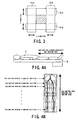
- the X-ray tube 20 On one end of the C-shaped arm 13 supported by the C-shaped arm support mechanism 12, the X-ray tube 20 is secured to face the tabletop 15. On the frontal surface of the X-ray tube 20 are provided an X-ray collimator 21 and a compensation filter 22 (refer to Fig. 2 ).
- the X-ray collimator 21 is in charge of collimating a region on the object, onto which an X-ray beam is radiated from the X-ray tube 20, into a desired one, with the result that the X-ray is prevented from being radiated onto unnecessary portions of the object.
- This X-ray collimator 21 is configured to, for example, as shown in Fig.
- each of the collimating blades 21a to 21d is connected to a servo motor via a rack-and-pinion mechanism and driven by those components such that the two opposed collimating blades 21a and 21b (21c and 21d) come closer to each other or depart away from each other.
- Those movements of the blades are able to form a desired radiation range through which the X-ray beam passes (refer to a hatching area called "radiation field" or "collimating opening”).
- the compensation filter 22 is used to attenuate the amount of the X-ray in part in an X-ray radiation range.
- the X-ray tube 20, X-ray collimator 21, and compensation filter 22 are secured so that they can move back and forth from and toward the tabletop 15 at the one end of the C-shaped arm 13 (as shown by arrows "I").
- the X-ray detector 30 is secured to be opposed to the X-ray tube 20 via the tabletop 15.
- this X-ray detector 30 is provided with an image intensifier (hereinafter referred to as I.I.) 31 and a TV camera 32 with an imaging tube or a solid imaging device (such as CCD: Charge Coupled Device), and an optical system 33 placed to combine both the I.I. 31 and the TV camera 32.
- An X-ray grid 34 is placed on the front of the I.I. 31 (that is, on the plane of the I.I. 31 that faces the tabletop 15).
- the X-ray detector 31 receives X-rays transmitted through an object P after being radiated from the X-ray tube 20, and converts the received X-rays into an optical image. This optical image is made to enter the TV camera 32 via the optical system 33 to be converted to a TV video signal.
- the X-ray grid 34 is responsible for preventing scattered X-rays caused in the object P from entering the I.I. 31.
- the X-ray detector 30, which is constructed as above, is configured to be movable in a direction coming closer to the tabletop 15 and returning to the C-shaped arm 13, as shown by arrows J in Fig. 1 .
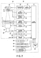
- Fig. 2 is a system diagram showing the devices composing the controller 50, besides both the X-ray tube 20 and X-ray detector 30 attached to the support apparatus 10.
- the controller 50 comprises a system controller 51, an operation panel 52, a high-voltage generator 53, an X-ray controller 54, an X-ray collimating controller 55, a compensation-filter controller 56, and a support-apparatus controller 57.
- the system controller 51 plays a centric role for integrally controlling the entire operation of the X-ray diagnostic apparatus.
- the operation panel 52 is provided with a keyboard and/or a touch panel and a pointing device such as mouse and track ball, which are used by an operator to give commands to the system controller 51.
- the high-voltage generator 53 generates a high-voltage signal to be applied to the X-ray tube 20.
- the X-ray controller 54 controls the operation of the high-voltage generator 53.
- the X-ray collimating controller 55 is to control amounts to be moved of the collimating blades 21a to 21d, which give a desired X-ray radiation field, that is, a desired opening of the X-ray collimator 21.
- the compensation-filter controller 56 is designed to control positions and others of the compensation filter 22.
- the support-apparatus controller 57 is mainly in charge of controlling the operations of both the C-shaped arm support mechanism 12 and the C-shaped arm 13 supported by the mechanism 12 as well as the operations of both the tabletop support mechanism 14 and the tabletop 15 supported by the mechanism 14.
- the controller 50 is still provided with an I.I. controller 58 controlling the operation of the I.I. 31, a TV camera controller 59 controlling the operation of the TV camera 32, an image processor 60, an image data storage 61, an image processor 60, and a display unit 62.
- the image data storage 61 is placed to memorize data of images acquired by the TV camera 32 and processed by the image processor 60, together with X-ray control conditions required by the X-ray controller 54, X-ray collimating controller 55, and compensation-filter controller 56, data of imaging realized by the support-apparatus controller 57, image processing conditions required by the image processor 60, and others.
- the image processor 60 is configured to apply various types of processing, such as gradation processing, spatial filtering, addition, and/or subtraction, to image data read out from the image data storage 61 and/or image data acquired in real time from the TV camera 32.
- the display unit 62 is placed for real-time visualization of images acquired by the TV camera 32 and/or display of images processed by the image processor 60.
- the controller 50 is still provided with a collimating position/size/angle calculator 63, an imaging parameter storage 64, and an imaging parameter controller 65.
- the collimating position/size/angle calculator 63 uses the data of an image stored in the image data storage 61 so that data indicative of a collimating position, size and angle appropriate for the image is calculated in the form of graphic data on the basis of a positional signal from the X-ray collimating controller 55 when the image is acquired.
- the imaging parameter storage 64 calculates, for a plurality of regions, movement speeds appropriate for the C-shaped arm 13 on the basis of information about both movement points to be interest of an X-ray contrast agent and imaging positions and memorizes the calculated results together with the position and size of the collimator and a temporal interval for imaging.
- the imaging parameter controller 65 is responsible for controlling the X-ray collimating controller 55, support-apparatus controller 57, and others using positional information and a specified imaging sequence so that the C-shaped arm 13 is moved at a proper speed. Such proper speeds are stored, imaging sequence by imagining sequence, in the imaging parameter storage 64.
- a width direction of an object P to be examined who is laid on the tabletop 15 is an X-direction
- a body-axis direction of the object P is a Y-direction
- a thickness direction of the object P is a Z-direction.
- fluoroscopic imaging involving the injection of an X-ray contrast agent is carried out over a wide area from the pelvis region to the tiptoes of an object P to be examined and an opening of the X-ray collimator 21 is determined at every region of the object P. That is, the fluoroscopic imaging is carried out as a pre-scan that uses the contrast agent.
- a small quantity of X-ray contrast agent is bolus-injected into the lower limb of an object to be examined and a lower-strength of X-ray is radiated toward the object so that X-ray transmission data for positioning for a main scan can be acquired.
- the scanning is performed part by part, with the tabletop 15 kept stationary, as the C-shaped arm 13 (i.e., both the X-ray tube 20 and the X-ray detector 30) is moved along the longitudinal direction of the tabletop 15 (i.e., the Y-direction).
- the C-shaped arm 13 is moved by making the C-shaped arm support mechanism 12 travel along the directions of the arrows "A" in Fig. 1 under the operation of the support-apparatus controller 57.
- a rotation angle and/or an oblique angle of the C-shaped 13 with respect to the tabletop 15 can be designated as desired angular amounts (refer to the directions shown by the arrows B and C in Fig. 1 ).
- Fig. 4A employs arrows to outline a partial range of an object P subjected to X-ray imaging in cases where the lower-limb contrast angiography is performed.
- Fig. 4B shows a long image of the entire lower limb, made by connecting partial images previously acquired through the fluoroscopic imaging. On the entire lower-limb image, as shown in Fig. 4B , an opening of the X-ray collimator 21 is given every region, the openings being for the main scan.
- an X-ray contrast agent is injected to an object P to be examined, and as shown in Fig. 4A , an area shown by the arrows is subject to several times of fluoroscopic imaging, thereby providing a fluoroscopic image every time of imaging.
- the resultant fluoroscopic images are then stored in turn into the image data storage 61.
- the fluoroscopic image data is read out image by image from the image data storage 61, and then sent to the image processor 60 where the data of respective images undergoes the mutual connection to form an entire image.
- the entire image of the lower limb is displayed as a long-plate image on the display unit 62.
- an operator uses the pointing device on the operation panel 52 to set, every region divided arbitrarily, to the image, a desired size of the X-ray collimator 21 which will be appropriate for the main scan.
- a desired size of the X-ray collimator 21 which will be appropriate for the main scan.
- the opening of the X-ray collimator 21 is defined as "1" at an imaging position "1.”
- the opening of the X-ray collimator 21 is defined as "2”
- the opening of the X-ray collimator 21 is defined as "3”
- so on that is, at the imaging position "n”
- the opening of the X-ray collimator 21 is defined as "n”). It is not always true that the openings 1, 2, 3, ..., n of the X-ray collimator 21 are different from each other, but one may be the same amount as others depending on imaging positions.
- the respective collimating openings are decided at the respective imaging positions through the operator's manual operations involving the use of the pointing device.
- the collimating position/size/angle calculator 63 calculates amounts to be moved of the blades 21a to 21d of the X-ray collimator 21 in both the X- and Y-directions. Data of calculated results is stored into the imaging parameter storage 64.
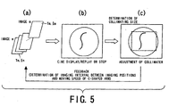
- a plurality of X-ray fluoroscopic images which is acquired in advance by fluoroscopic acquisition under a pre-scan to be carried out before an imaging scan, is read out from the image data storage 61 to display the fluoroscopic images in a tracing manner.
- a feed-back flow is used to the tracing display and its processing, in which various imaging parameters including both a frame rate "f" and movement speeds of the C-shaped arm 13 can be determined according to flowing speeds of an X-ray contrast agent injected into the lower limb of the object P.
- FIG. 5 Plural fluoroscopic images are acquired in advance with the X-ray contrast agent injected into the object, and data of the resultant fluoroscopic images is stored in the image data storage 61, which is pictorially depicted in Fig. 5(a) .
- Such fluoroscopic images are displayed on the screen of the display unit 62 as a cine image or a tracing image at a predetermined frame rate, as shown in Fig. 5(b) .
- Fig. 5(a) pictorially shows plural frames of images from the m-th frame to the n-th frame, all of which are stored in the image data storage 61.
- Fig. 5(b) An operator thus makes the fluoroscopic images on the display unit 62 in sequence, as shown in Fig. 5(b) , during which time the operator observes how the injected contrast agent flows in each image.
- the replay on the screen is stopped to freeze the image.
- a dashed-line frame showing an opening of the X-ray collimator 21 is placed on the frozen image, the dashed-line frame being set to an appropriate size and position for an imaging scan to be carried out after the pre-scan and limiting the X- and Y-directional positions of the blades 21a to 21d.
- the X-ray collimating controller 55 is activated to enable the above setting operations.
- an interval between frames of peak-traced images is "m to n,” so that, using positional information ln and lm about the specified two points and temporal elapse information Tn and Tm based on the frame rate "f," a moving speed ⁇ of the X-ray contrast agent is given by the following formula (1).
- ⁇ ln - lm / Tn - Tm
- the moving speed ⁇ is faster than a moving speed of the C-shaped arm 13 under the imaging scan, there is a possibility that the top position of flow of the contrast agent becomes outside the image (in this case, the image fails to trace the flow of the contrast agent).
- the opening of the X-ray collimator 21 in the Y-direction is reset to a large amount or the frame rate "f" is reset to a high value.
- an error ⁇ is automatically added to the opening, the error being a margin for continuously connecting the images each defined by the opening of the X-ray collimator 21 at each imaging position when the entire area to be scanned is displayed in a long sheet-like image.
- the pieces of information indicative of the temporal elapse times Tm and Tn and the imaging positions lm and ln are used as aid information for deciding the imaging interval "K" between imaging positions and the frame rate "f.”
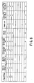
- Imaging regions i.e., imaging positions
- various imaging parameters set values
- the imaging parameters include a variety of set values, such as positions, rotation angles, oblique angles and speeds of the C-shaped arm 13, and speeds of the X-ray contrast agent.
- the imaging parameters are stored into the imaging parameter storage 64 in the form of a data table shown in, for example, Fig. 6 .
- an imaging scan for acquiring images to be actually diagnosed is performed.
- the imaging scan consists of a scan based on a mask sequence, which is carried out before injecting the X-ray contrast agent into an object to be imaged and a scan based on a contrast sequence, which involves the X-ray contrast agent to be injected for the scan.
- the scan on the mask sequence is carried such that, under the control of the imaging parameter controller 65, an object in which the X-ray contrast agent yet to be injected is subjected to the scan on the mask sequence under the imaging parameters decided using the foregoing fluoroscopic image acquired by the pre-scan. That is, imaging the lower limb of the object at each imaging position and its data is stored, together with its positional information, into. the image data storage 61.
- an X-ray contrast agent is injected to the object, and a scan based on the contrast sequence is carried out toward the object along a direction of flow of the contrast agent under the control of the imaging parameter controller 65.
- This scan is done in the same way as the scan based on the mask sequence, thereby a contrast image being produced at each imaging position.
- both the imaging parameters such as a moving speed of the C-shaped arm 13 and information about an elapse time counted after the injection of the contrast agent is supplied to the imaging parameter controller 65 in sequence.
- the imaging parameter controller 65 is allowed to perform the imaging according to the conditions read out from the Imaging parameter storage 64.
- the image data is stored, together with their positional information, into the image data storage 61.
- the image processor 60 works in such a manner the processor reads out the previously acquired mask images from the image data storage 61 and performs subtraction between the contrast image data and the read-out mask image data to obtain data of a difference image (subtraction image) at each imaging position.
- the data of the difference images at the respective imaging positions are then stored, together with information about the imaging positions, into the image data storage 61 and displayed in real time on the display unit 62.
- the contrast images and the mask images, which are subjected to the subtraction are acquired from, of course, the same region of the object.
- Each of the difference images presents only a path through which the contrast agent passed, with the background image removed thanks to the subtraction.
- imaging parameters a variety of types of set values (i.e., imaging parameters) are read out from the imaging parameter storage 64, and, under the control of the system controller 51, used to obtain both the mask images and the contrast images in compliance with the set values. It is therefore possible to produce an image proper for diagnosis every imaging region along the object's lower limb, thus an operational burden on the operator being lessened to a great degree.
- the angle and position of the C-shaped arm 13 are first set to their initial values. Practically, the angle and position of the C-shaped arm 13 to the tabletop 15 are detected, and the detected values are subjected to whether or not they are shifted from their initially set values. If there are some shifts, the support-apparatus controller 57 works to correct such shifts. A command for the correction is issued from the system controller 51.
- step S11 the set values stored in the imaging parameter storage 64 (as shown in Fig. 6 ) is searched for an opening of the X-ray collimator 21 (i.e., X- and Y-directional positions of all the blades 21 a to 2 1 d) at the current imaging position.
- Data of the searched opening is used by the X-ray collimating controller 55, with the result that the opening of the X-ray collimator 21 is set to the specified one. This setting operation is also done under the control of the system controller 51.
- step S12 the processing is shifted to step S12, where the set values in the imaging parameter storage 64 is subjected to search for a moving speed beta of the C-shaped arm 13 at the current imaging position.
- the data of both the opening of the X-ray collimator 21 and the moving speed beta of the C-shaped arm 13 is then transmitted to the imaging parameter storage 65.
- the imaging parameter controller 65 works such that both the mask images and the contrast images are produced through the imaging scan.
- an operator when obtaining the contrast images in the imaging scan, an operator is allowed to keep on pushing an Imaging button (not shown) on the operation panel 52, during which time the operator observes the contrast images displayed in real time on the display unit 62.
- Such a pushing operation enables the C-shaped arm 13 to move to follow the flow of the contrast agent in an automatic fashion, so that the contrast images are acquired during the pushing operation.
- a joystick or any other operation means (not shown) on the operation panel is manually operated instead of the foregoing button, thus the C-shaped arm. 13 being switched to a manual operation to follow the contrast agent. In this case, only the X-ray collimator 21 is still automatically operated.
- a modification which is concerned with, as shown in Fig. 8 , the display of a profile between relationships of the positions of the C-shaped arm 13 and the moving speeds of the contrast agent and the C-shaped arm 13.
- This profile display can be done based on information from the data table in the imaging parameter storage 64 (refer to Fig. 6 ), thereby effectively making use of the imaging parameters to provide another kind of diagnostic information.
- FIG. 9 Another modification is illustrated by Fig. 9 , in which an image useful for diagnosis is read out from the images stored in the image data storage 61 and subjected to cine display on the display unit 62. Both a measuring start point and a measuring end point of the X-ray contrast agent can also be overlaid on the cine displayed image and data indicative of a measured moving speed of the contrast agent or any other type of necessary information is also shown on the cine displayed image. This way of display is able to timely provide a physician with information useful for diagnosis.
- a pointing device on the operation panel 52 is used to arbitrarily place a region of interest (ROI), which makes it possible to read out data of a difference image corresponding to the region specified by the ROI from the image data storage 61, and to display the read-out image on the display unit 62.
- ROI region of interest
- the read-out image, which is specified by the ROI is made up of a plurality of images m1 and m2, those images m1 and m2 can be connected and displayed on the display unit 62, as shown in Fig. 10B .
- information about a moving speed of the contrast agent or others can be displayed in an overlay manner.
- the speed of flow of such a branched blood vessel is slower than that of the straight portions such as crural areas and second thighs.
- the flow of the X-ray contrast agent is also made slower in the joint portions. Accordingly, if such joint portions are particularly interested for observation, such portions can be specified in advance.
- the X-ray collimating controller 55 is configured to control the X-ray detector 21 such that the opening thereof (for instance, a narrower opening) proper for imaging the contrast agent of which flow speed is slower at the specified position (region). This control manner is more effective in reducing an operational burden on operators.
- a pointing device on the operation panel 52 is also used to place, at a desired region, a ROI showing the particularly interested region.
- Information about this placement is stored in the imaging parameter storage 64 via the system controller 51.
- the imaging parameter controller 65 operates to allow the thus-set information to be read out from the storage 64, the read-out information is sent to the X-ray collimating controller 55 via the system controller 51.
- the opening of the X-ray collimator 21, that is, an X-ray radiated field is adjusted to an optimum size according to the read-out information at the region of interest. This field control is helpful for lessening an amount of X-ray exposure, with an operational burden reduced.
- the C-shaped arm arrives at a region where the contrast agent flows relatively slowly, the frame rate can be lowered to further relieve an X-ray exposure amount.
- the present first embodiment features, that the routine to set imaging parameters for the imaging scan using a fluoroscopic image acquired through the pre-scan can be automated, not manually performed by an operator.
- the X-ray diagnostic system In order to automatically set the imaging parameters, the X-ray diagnostic system according to the first embodiment is newly provided, as shown in Fig. 11 , with a skeleton processor 70 to extract and process skeletons as patterns of the X-ray contrast agent injected in an object.
- the operation panel 52 is equipped with a dead man's switch 71 as an additional switch.
- the remaining hardware configurations are identical or similar to those used by the first example useful for understanding the present invention.
- the skeleton processor 70 is provided as a processor of which main configuration is a computer equipped with a CPU and memories for memorizing programs, for computation, and for memorizing data, though they are not shown.
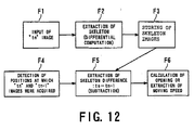
- skeleton processor 70 When the skeleton processor 70 Is activated, programs previously stored in the program memory are read out into the computing memory, and the processing is performed in accordance with the predetermined procedures described in the programs. The processing is outlined in Fig. 12 .
- the processing functionally realizes various components.
- These components includes an image input unit F1, skeleton extraction unit F2, storing unit F3, detecting unit F4, difference extraction unit (difference circuit) F5, and processing unit F6.
- the image input unit F1 inputs image data acquired by the pre-scan.
- the skeleton extraction unit F2 performs differential processing to extract a pattern of the X-ray contrast agent (hereinafter referred to as skeleton).
- the storing unit F3 operates to store skeleton image data in a memory
- the detecting unit F4 is in charge of positional detection of images acquired at time instants tn and tn-1, which are subjected to subtraction
- the difference extraction unit F5 performs the subtraction between two frames of skeleton data.
- the processing unit F6 is in change of calculation of collimating openings and detection of moving speeds of the C-shaped arm 13.
- the skeleton processor 70 is configured to execute the processing shown in each of Figs. 13 and 14 , for example, in a time sharing manner during the performance of a pre-scan (i.e., preparation scan).
- the processing in Fig. 13 shows the procedures for determining collimating openings of the X-ray collimator 21, while the processing in Fig. 14 shows the procedures for determining relative moving speeds of one of the C-shaped arm 13 and the tabletop 15 to the other (in the present embodiment, the C-shaped arm is moved with the tabletop 15 in position).
- the skeleton processor 70 may execute only either the processing in Fig. 13 or the processing in Fig. 14 .
- the skeleton processor 70 inputs the data of images acquired at a certain imaging position (plural sampling timings tn) from the image data storage 60 through the system controller 51, the image data being acquired under the current pre-scan (step S51). The skeleton processor 70 then reads out, from its internal image data memory image, data of a skeleton of the contrast agent, which were acquired at the last imaging position (plural sampling timings tn-1) and already processed (step S52).
- the skeleton processor 70 performs the extraction of a skeleton extraction, the production of a difference image, and the determination of a collimating opening, in sequence.
- a skeleton of the X-ray contrast agent at the certain imaging position subjected to the plural sampling timings tn is extracted by performing differential processing (recognized as a pattern), and then the image data at the pixels of the skeleton is temporarily stored in the internal memory (step S53). Then, the skeleton images at both of the imaging positions (sampling timings tn and tn-1) undergo subtraction, pixel by pixel, so that a difference image is produced (step S54). This production of the difference image is pictorially shown in Fig. 15 .
- step S55 the data of the difference image is subjected to calculation of an amount of difference (i.e., an area of difference) and it is determined whether or not the amount of difference is equal to or more than a predetermined threshold (step S55). If the amount of difference is equal to or more than the predetermined threshold, a collimating opening of the X-ray collimator 21 which depends on the amount of difference, that is, an area of the skeleton is determined with reference to, for example, a first data table previously set, thereby data indicative of the determined collimating opening being stored into the internal memory (step S56).
- an amount of difference i.e., an area of difference
- a collimating opening of the X-ray collimator 21 which depends on the amount of difference, that is, an area of the skeleton is determined with reference to, for example, a second data table previously set differently from the first data table, thereby data indicative of the determined collimating opening being stored into the internal memory (step S57).
- Applying the threshold processing to the amount of difference allows the collimating opening to be determined in detail and in a simple manner in dependence upon how fast the X-ray contrast agent flows.
- step S51 image data acquired by the pre-scan at the next imaging position (plural sampling timings tn+1) is read out again (step S51), so that the foregoing processing is repeated.
- a fluoroscopic image acquired by the pres-can under a planned sampling rate based on an experimental value is displayed in real time.
- the data of the fluoroscopic image is then subjected to differential processing to extract the skeleton of the X-ray contrast agent at respective imaging positions.
- a difference image between the skeleton images extracted at this time of imaging position (plural sampling timings tn) and the last imaging position (plural sampling timings tn-1) is produced.
- How to produce the difference image is pictorially exemplified in Fig. 15(a) to (c) .
- a collimating opening at a certain imaging position (as shown in Fig. 15(c) , in which a region RG enclosed by a dashed line shows an optimum collimating opening) can be decided and a flow speed of the X-ray contrast agent can be calculated.
- the skeleton processor 70 inputs the data of images acquired at a certain imaging position (plural sampling timings tn) from the image data storage 60 through the system controller 51, the image data being acquired under the current pre-scan (step S61).
- the skeleton processor 70 then reads out, from its internal image data memory image, data of a skeleton of the contrast agent, which were acquired at the last imaging position (plural sampling timings tn-1) and already processed (step S62).
- the skeleton processor 70 performs the extraction of a skeleton, the production of a difference image, and the determination of a moving speed of the C-shaped arm 13, in sequence.
- a skeleton of the X-ray contrast agent at the certain imaging position subjected to the plural sampling timings tn is extracted by performing differential processing (recognized as a pattern), and then the image data at the pixels of the skeleton is temporarily stored in the internal memory (step S 6 3). Then, the skeleton images at both of the imaging positions (at sampling timings tn and tn-1) undergo subtraction, pixel by pixel, so that a difference image is produced (step S64). This production of the difference image is pictorially shown in Fig. 16 .
- step S65 the data of the difference image is subjected to calculation of an amount of movement of the X-ray contrast agent, and it is determined whether or not the amount of movement is equal to or more than a predetermined threshold (step S65). If the amount of movement is equal to or more than the predetermined threshold, a moving speed of the C-shaped arm 13 which depends on a larger skeleton area (a larger collimating opening) is determined with reference to, for example, a third data table previously set, thereby data indicative of the determined moving speed being stored into the internal memory (step S66).
- a moving speed of the C-shaped arm 13 which depends on a smaller skeleton area (a smaller collimating opening) is determined with reference to, for example, a fourth data table previously set differently from the third data table, thereby data indicative of the determined moving speed being stored into the internal memory (step S67).
- Applying the threshold processing to the amount of movement allows the moving speed of the C-shaped arm 13 to be determined in detail and in a simple manner in dependence upon how fast the X-ray contrast agent flows.
- step S61 image data acquired by the pre-scan at the next imaging position (plural sampling timings tn+1) is read out again (step S61), so that the foregoing processing is repeated.
- a fluoroscopic image acquired by the prescan under a planned sampling rate based on an experimental value is displayed in real time.
- the data of the fluoroscopic image is then subjected to differential processing to extract the skeleton of the X-ray contrast agent at respective imaging positions.
- a difference image between. the skeleton images extracted at the current imaging position (plural sampling timings tn) and the last imaging position (plural sampling timings tn-1) is produced. How to produce the difference image is pictorially exemplified in Fig. 16(a) to (c) and (d) to (f) .
- a collimating opening at a certain imaging position (a representative imaging time t1) can be decided, for example, as shown by a region P1 (x, y) enclosed by a dashed line in Fig. 16(c) ) and the other collimating opening at the next imaging position (a representative imaging time t2) can be decided, for example, as shown by a region P2(x, y) enclosed by a dashed line in Fig. 16(f) ) (steps S65 and S66 in Fig. 14 ).
- the data of the calculated moving speed V of the C-shape arm 13 is stored into the imaging parameter storage 64.
- the imaging parameters necessary for the imaging scan are stored in the imaging parameter storage 64.
- the imaging parameter controller 65 is allowed to read out the imaging parameters, and used in the imaging scan. That is, the collimating opening of the X-ray collimator 21 is automatically adjusted according to its data predetermined every imaging region (position) using the fluoroscopic image acquired by the pre-scan and each imaging region is subject to the imaging scan at a desired frame rate "f" and a desired imaging interval "K" between imaging positions, so that the C-shaped arm 13 is moved to the next imaging region (position) follow the flow of the X-ray contrast agent.
- the pre-scan provides a fluoroscopic image, during which time the skeletons of the flow of the X-ray contrast agent are recognized as patterns, and collimating openings are obtained almost in real time from information about the recognized patterns and stored in the imaging parameter storage 64.
- the imaging parameter controller 65 reads out the information about the collimating openings from the imaging parameter storage 64 and sends them to the X-ray collimating controller 55 via the system controller 51. This alloWs the collimating opening of the X-ray collimator 21 to be adjusted to each value specified by the X-ray collimating controller 55 almost in real time during the pre-scan.
- the flow speed of blood in a lesion that is, the flow speed of the X-ray contrast agent Is slower.
- using the automatic trace function of the contrast agent skeletons makes it possible that the collimating opening of the X-ray collimator 21 is set to a narrow value at the imaging region including the lesion.
- An imaging region (position) including the lesion can be determined by assigning the thresholds used in the determination of the amounts of difference and/or movement in Figs. 13 and/or 14 to proper values based on, for example, experimental results.
- the fluoroscopic image produced by the pre-scan is used for the pattern recognition of the contrast agent skeletons.
- the information resulting from the pattern recognition is the determination of the imaging parameters, such as the opening of the X-ray collimator 21, the flow speed of the X-ray contrast agent, the moving speed of the C-shaped arm 13, at each imaging position under the imaging scan.
- the determined imaging parameters are automatically memorized into the imaging parameter storage 64.
- the foregoing automatically set imaging parameters are read out under the control of the Imaging parameter controller 65, and automatically sent to both the X-ray collimating controller 55 and the support-apparatus controller 57 via the system controller 51.
- the imaging parameters automatically set on the fluoroscopic image acquired in the pre-scan are used in the same manner as that in the first embodiment, in . which the imaging scan is carried out with both the collimating opening and the C-shaped arm moving speed adjusted in an automatic fashion.
- the installment of the dead man's switch 71 ensures the occurrence of emergency cases is treated in a sure manner. As long as the operator pushes down the dead man's switch 71, this X-ray diagnostic system is permitted to work in its normal conditions. On the other hand, when abnormal states occur concerning the 7C-ray tube, C. shaped arm, tabletop and others, the operator stops operating (pushing) the dead man's switch 71, which has been pushed so far, thus making it possible to avoid such abnormal states immediately.
- the foregoing embodiment has employed the X-ray detector 30 equipped with the I.I. 31 and the TV camera 32 combined by the optical system 33, but this is not a definitive list.
- a semiconductor-array flat panel detector (FPD) for detecting the X-ray can be employed as well, in which electrical circuitry composed of switching elements, capacitors and others which are formed on a glass-made substrate is covered by a photo-electric film to covert radiation rays to electric charges.
- FPD semiconductor-array flat panel detector
- the C-shaped arm 13 can be made stationary if the tabletop 15 is moved for the X-ray imaging. Moreover, if necessary, both the C-shaped arm 13 and the tabletop 15 can be moved to produce a relative movement therebetween.
Description
- The present invention relates to a system for X-ray diagnosis of an object in which an X-ray contrast agent is injected, and in particular, to the method and system preferable to an examination for angiography of a lower limb of the object.
- An X-ray diagnostic system is one of medial imaging modalities that can be utilized for examination and diagnosis for various regions of an object to be examined. One of the examinations carried out by the X-ray diagnostic system is lower-limb angiography of the object.
- The lower-limb angiography under the X-ray diagnostic system is carried out such that an X-ray contrast agent is injected into the artery of an object at the groin portion thereof and an X-ray is scanned to track a flow of the contrast agent. Hence the scanning is carried out over a wide range from a region near to the pelvis to the tiptoes. It is difficult to obtain an entire image of such a wide range through one time of imaging, and several times of imaging is carried out to cover such a wide range. The resultant partial images are combined to form the entire image. Since this imaged range contains different parts, such as crural areas, knees, second thighs, and malleolus portions, of which sizes (widths and lengths) are different from each other, halation will occur if, for example, the second thighs are scanned on condition that a range to be X-ray radiated is assigned to a size to be fit to the pelvis. The halation, if occurring, will degrade the quality of images.
- To avoid such a drawback, a conventional technique has been provided, which requires that a width-directional opening of an X-ray collimator be adjusted such that an X-ray will not be radiated outside beyond the contour of an object to be scanned.
- Another conventional technique for preventing the halation has been known by
Japanese Patent Laid-open publication No. 6-217973 - However, an actual blood flow speed is not constant over the wide region from the pelvis to the tiptoes. In such a wide region, there are various portions in which the blood flows at slower speeds and the blood flows at faster speeds. Furthermore, such a wide region includes some portions through which blood vessels run in simple and/or complicated ways. Hence if the lower limb is imaged with the movements of scanning positions in the condition in which the longitudinal opening of the X-ray collimator (that is, the opening of the X-ray collimator in a direction along the lower limb of an object) is held constant, the resultant images suffer from having some portions that are insufficient for diagnosis.
- To overcome this difficultly, it may be possible to employ a technique in which an imaging interval along the direction of the lower limb of an object is shortened to increase the number of times of imaging. Such a technique forces the longitudinal opening of the X-ray collimator to be narrowed, so that the foregoing difficulty can be improved, but an operator should accept a narrowed display area of scanned images and is obliged to track the flow of the contrast agent for imaging by using the narrower-display-area images. Hence the operations for the imaging are complicated and ballooned.
- HILBERTZ TH ET AL, 'PERIVISION - EIN NEUER STANDARD FUER DIE PERIPHERE ANGIOGRAPHIE' ELECTRO MEDICA (SIEMENS), SIEMENS A.G. ERLANGEN, DE, vol. 60, no. 1, 1992, pages 2-5 describes an X-ray system where there is relative movement between the X-ray source and detection and the patient.
-
US5450464 (Sakakibara ) discloses an X-ray system that automatically tracks the flow of contrast agent through the body during a fluoroscopic scan and controls the motion of a patient relative to the system in accordance with the flow of a contrast agent through the patient. -
US6055295 (Murthy et al. ) discloses an X-ray system where the collimator aperture is varied to prevent X-ray exposure of non-body regions. -
US5386450 (Ozawa ) discloses a system that tracks the flow of contrast agent through the body using a temporal differential image technique. -
US6052476 (Qian et al. ) describes the temporal control of the motion of an X-ray imaging device so as to maximise the contrast of the resulting image, the temporal control being in accordance with the flow of contrast agent through the patient. - The present invention has been made with due consideration to the foregoing difficulties, and an object of the present invention is to provide an X-ray diagnostic system capable of making it possible X-ray scanning in the most suitable conditions to track the flow of an X-ray contrast agent injected in an object to be examined and of lessening an operator's burden so as to improve the operationality.
- In order to realize the foregoing object, according to one aspect of the present invention, in a first aspect there is provided an X-ray diagnostic system as defined in claim I.
- It is therefore possible for the X-ray diagnostic system to control an X-ray radiated filed on an object on the track of a flow of an X-ray contrast agent, whereby higher-grade X-ray radiography images are provided. In addition, an operational burden on physicians can be reduced to a great extent, thus providing the X-ray diagnostic system with improved operationality.
- The imaging parameter setting unit is configured to, from the fluoroscopic image obtained by the fluoroscopic scan unit, automatically recognize the region through which the X-ray contrast agent flows and to set the imaging parameters based on a recognized result of the automatic recognition. This automatic recognition allows the flow of the X-ray contrast agent to be traced automatically during the fluoroscopic scan, so that an opening of the X-ray collimator can be adjusted substantially in real time even under the fluoroscopic scan. The automatic recognition of flow of the contrast agent provides a flowing speed and an amount of movement thereof. These pieces of information about the contrast agent are used to automatically determine imaging parameters, such as an X-ray collimating opening at each imaging position and a relative moving speed between both the tabletop and the support apparatus, thus remarkably lowering an operational burden on physicians.
- In the accompanying drawings:
-
Fig. 1 is a perspective view outlining the configuration of a support apparatus of an X-ray diagnostic system according to an example useful for understanding the present invention: -
Fig. 2 is an electrical block diagram showing the X-ray diagnostic system according to a first example useful for understanding the present invention; -
Fig. 3 is a plan view explaining operations of an X-ray collimator equipped in the X-ray diagnostic system; -
Fig. 4A is an illustration showing an imaging area subjected to both a pre-scan and an imaging scan; -
Fig. 4B explains how to manually set an opening of the X-ray collimator at each imaging region in the first example useful for understanding the present invention; -
Fig. 5 explains one example of how to set a proper imaging condition at each imaging region in the first example useful for understanding the present invention; -
Fig. 6 explains a table formed in a memory, set values indicative of imaging parameters determined through the setting operations for the imaging conditions; -
Fig. 7 is a flow chart exemplifying imaging procedures for a desired area of an object to be examined, the imaging procedures including operator's manual operations: -
Fig. 8 explains, in the first example useful for understanding the present invention, a function for displaying profiles of movement speeds of an X-ray contrast agent and a C-shaped arm: -
Fig. 9 explains another function for determining a movement speed of the X-ray contrast agent; -
Figs. 10A and 10B still explain another function for determining a movement speed of the X-ray contrast agent; -
Fig. 11 is a block diagram showing an outlined electrical configuration of an X-ray diagnostic system according to a first embodiment of the present invention; -
Fig. 12 is a functional block diagram outlining processing carried out by a skeleton processor employed by the X-ray diagnostic system in the first embodiment; -
Fig. 13 is a flow chart outlining an example for automatically setting collimating openings of the X-ray collimator at respective imaging positions, the setting processing being performed by the skeleton processor, -
Fig. 14 is a flow chart outlining an example, for automatically setting movement speeds of the C-shaped arm at respective imaging positions, the setting processing also being performed by the skeleton processor, -
Fig. 15 is an explanation for automatically setting an opening of the X-ray collimator using extraction of skeletons of the X-ray contrast agent and subtraction thereof; and -
Fig. 16 is an explanation for automatically setting a movement speed of the C-shaped arm using extraction of skeletons of the X-ray contrast agent and subtraction thereof. - An example useful for understanding the present invention and a preferred embodiment of an X-ray diagnostic system according to the present invention will now be described in detail with reference to the accompanying drawings.
- Example useful for understanding the present invention.
- Referring to
Figs. 1 to 7 , a first example useful for understanding an X-ray diagnostic system according to the present invention will now be detained. - The X-ray diagnostic system according to this example is equipped with a
support apparatus 10, anX-ray tube 20, anX-ray detector 30 and acontroller 50. -
Fig. 1 is a perspective view outlining a partial configuration of thesupport apparatus 10 of the X-raydiagnostic system 10. Thissupport apparatus 10 has, as the main components, a supporting main unit 1.1, a C-shapedarm support mechanism 12, a C-shapedarm 13, atabletop support mechanism 14, and atabletop 15. - The supporting
main unit 11 Is fixed on the floor and slidably supports the C-shapedarm support mechanism 12 in a direction approximately parallel with the floor (as shown by arrows "A" inFig. 1 ). The C-shapedarm 13 is attached to the C-shapedarm support mechanism 12 such that thearm 13 is rotatable along a plane approximately perpendicular to the floor about an arm attachment position to the mechanism 12 (as shown by arrows "B" inFig. 1 ) and is slidable in an arch-like direction (shown by arrows "C" inFig. 1 ). As a result, the C-shapedarm 13 can be tilted to thetabletop 15 which will be described later. Though described later, both of theX-ray tube 20 and the X-ray detector 3C are secured on the C-shapedarm 13 with thetabletop 15 located therebetween. - The
tabletop support mechanism 14 is supported by the supportingmain unit 11 in such a manner that themechanism 14 can be moved up and down (as shown by arrows "D" inFig. 1 ) and rotated (as shown by arrows "E" inFig. 1 ). - The
tabletop 15 is secured on thetabletop support mechanism 14 so that thetabletop 15 is slidable in a width direction thereof (as shown by an arrow "F" inFig. 1 ) is movable in a thickness direction of the tabletop 15 (as shown by arrows "G" inFig. 1 ). In addition, thetabletop 15 is secured to be able to rotate about a central axis along its longitudinal direction (as shown by arrows "H" inFig. 1 ). As pictorially shown inFig. 2 , a patient P (i.e., an object) to be examined is laid on thetabletop 15. - On one end of the C-shaped
arm 13 supported by the C-shapedarm support mechanism 12, theX-ray tube 20 is secured to face thetabletop 15. On the frontal surface of theX-ray tube 20 are provided anX-ray collimator 21 and a compensation filter 22 (refer toFig. 2 ). TheX-ray collimator 21 is in charge of collimating a region on the object, onto which an X-ray beam is radiated from theX-ray tube 20, into a desired one, with the result that the X-ray is prevented from being radiated onto unnecessary portions of the object. ThisX-ray collimator 21 is configured to, for example, as shown inFig. 3 , have plate-like collimating blades 21a to 21d made of lead and arranged in a double cross. Each of thecollimating blades 21a to 21d is connected to a servo motor via a rack-and-pinion mechanism and driven by those components such that the twoopposed collimating blades - The
compensation filter 22 is used to attenuate the amount of the X-ray in part in an X-ray radiation range. - The
X-ray tube 20,X-ray collimator 21, andcompensation filter 22 are secured so that they can move back and forth from and toward thetabletop 15 at the one end of the C-shaped arm 13 (as shown by arrows "I"). - Furthermore, on the other end of the C-shaped
arm 13, theX-ray detector 30 is secured to be opposed to theX-ray tube 20 via thetabletop 15. By way of example, as shown inFig. 2 , thisX-ray detector 30 is provided with an image intensifier (hereinafter referred to as I.I.) 31 and aTV camera 32 with an imaging tube or a solid imaging device (such as CCD: Charge Coupled Device), and anoptical system 33 placed to combine both the I.I. 31 and theTV camera 32. AnX-ray grid 34 is placed on the front of the I.I. 31 (that is, on the plane of the I.I. 31 that faces the tabletop 15). The I.I. 31 receives X-rays transmitted through an object P after being radiated from theX-ray tube 20, and converts the received X-rays into an optical image. This optical image is made to enter theTV camera 32 via theoptical system 33 to be converted to a TV video signal. TheX-ray grid 34 is responsible for preventing scattered X-rays caused in the object P from entering the I.I. 31. TheX-ray detector 30, which is constructed as above, is configured to be movable in a direction coming closer to thetabletop 15 and returning to the C-shapedarm 13, as shown by arrows J inFig. 1 . - The
controller 50, which is one of the main constituents of the present X-ray diagnostic apparatus and comparable to thesupport apparatus 10, will now be explained in connection withFig. 2. Fig. 2 is a system diagram showing the devices composing thecontroller 50, besides both theX-ray tube 20 andX-ray detector 30 attached to thesupport apparatus 10. - The
controller 50 comprises asystem controller 51, anoperation panel 52, a high-voltage generator 53, anX-ray controller 54, anX-ray collimating controller 55, a compensation-filter controller 56, and a support-apparatus controller 57. - Of these components, the
system controller 51 plays a centric role for integrally controlling the entire operation of the X-ray diagnostic apparatus. Theoperation panel 52 is provided with a keyboard and/or a touch panel and a pointing device such as mouse and track ball, which are used by an operator to give commands to thesystem controller 51. The high-voltage generator 53 generates a high-voltage signal to be applied to theX-ray tube 20. TheX-ray controller 54 controls the operation of the high-voltage generator 53. - Furthermore, the
X-ray collimating controller 55 is to control amounts to be moved of thecollimating blades 21a to 21d, which give a desired X-ray radiation field, that is, a desired opening of theX-ray collimator 21. The compensation-filter controller 56 is designed to control positions and others of thecompensation filter 22. The support-apparatus controller 57 is mainly in charge of controlling the operations of both the C-shapedarm support mechanism 12 and the C-shapedarm 13 supported by themechanism 12 as well as the operations of both thetabletop support mechanism 14 and thetabletop 15 supported by themechanism 14. - The
controller 50 is still provided with an I.I.controller 58 controlling the operation of the I.I. 31, aTV camera controller 59 controlling the operation of theTV camera 32, animage processor 60, animage data storage 61, animage processor 60, and adisplay unit 62. Theimage data storage 61 is placed to memorize data of images acquired by theTV camera 32 and processed by theimage processor 60, together with X-ray control conditions required by theX-ray controller 54,X-ray collimating controller 55, and compensation-filter controller 56, data of imaging realized by the support-apparatus controller 57, image processing conditions required by theimage processor 60, and others. - Furthermore, the
image processor 60 is configured to apply various types of processing, such as gradation processing, spatial filtering, addition, and/or subtraction, to image data read out from theimage data storage 61 and/or image data acquired in real time from theTV camera 32. Thedisplay unit 62 is placed for real-time visualization of images acquired by theTV camera 32 and/or display of images processed by theimage processor 60. - The
controller 50 is still provided with a collimating position/size/angle calculator 63, animaging parameter storage 64, and animaging parameter controller 65. Of these the collimating position/size/angle calculator 63 uses the data of an image stored in theimage data storage 61 so that data indicative of a collimating position, size and angle appropriate for the image is calculated in the form of graphic data on the basis of a positional signal from theX-ray collimating controller 55 when the image is acquired. - The
imaging parameter storage 64 calculates, for a plurality of regions, movement speeds appropriate for the C-shapedarm 13 on the basis of information about both movement points to be interest of an X-ray contrast agent and imaging positions and memorizes the calculated results together with the position and size of the collimator and a temporal interval for imaging. - The
imaging parameter controller 65 is responsible for controlling theX-ray collimating controller 55, support-apparatus controller 57, and others using positional information and a specified imaging sequence so that the C-shapedarm 13 is moved at a proper speed. Such proper speeds are stored, imaging sequence by imagining sequence, in theimaging parameter storage 64. - The operation of the above-configured X-ray diagnostic apparatus will now be explained in the case that the apparatus performs lower-limb angiography. In
Figs. 2 ,4A and 4B , the three mutually-orthogonal directions are defined such that a width direction of an object P to be examined who is laid on thetabletop 15 is an X-direction, a body-axis direction of the object P is a Y-direction, and a thickness direction of the object P is a Z-direction. - First, fluoroscopic imaging involving the injection of an X-ray contrast agent is carried out over a wide area from the pelvis region to the tiptoes of an object P to be examined and an opening of the
X-ray collimator 21 is determined at every region of the object P. That is, the fluoroscopic imaging is carried out as a pre-scan that uses the contrast agent. In this fluoroscopic imaging, a small quantity of X-ray contrast agent is bolus-injected into the lower limb of an object to be examined and a lower-strength of X-ray is radiated toward the object so that X-ray transmission data for positioning for a main scan can be acquired. - Since one time of scanning is almost impossible to provide an entire image of a desired region to be diagnosed, the scanning is performed part by part, with the
tabletop 15 kept stationary, as the C-shaped arm 13 (i.e., both theX-ray tube 20 and the X-ray detector 30) is moved along the longitudinal direction of the tabletop 15 (i.e., the Y-direction). Hence several pieces of partial images are obtained, and then connected to the entire image of the lower limb. The C-shapedarm 13 is moved by making the C-shapedarm support mechanism 12 travel along the directions of the arrows "A" inFig. 1 under the operation of the support-apparatus controller 57. To enable a desired region of the object to be depicted at the highest image quality, a rotation angle and/or an oblique angle of the C-shaped 13 with respect to thetabletop 15 can be designated as desired angular amounts (refer to the directions shown by the arrows B and C inFig. 1 ). -
Fig. 4A employs arrows to outline a partial range of an object P subjected to X-ray imaging in cases where the lower-limb contrast angiography is performed.Fig. 4B shows a long image of the entire lower limb, made by connecting partial images previously acquired through the fluoroscopic imaging. On the entire lower-limb image, as shown inFig. 4B , an opening of theX-ray collimator 21 is given every region, the openings being for the main scan. - Specifically, first of all, an X-ray contrast agent is injected to an object P to be examined, and as shown in
Fig. 4A , an area shown by the arrows is subject to several times of fluoroscopic imaging, thereby providing a fluoroscopic image every time of imaging. The resultant fluoroscopic images are then stored in turn into theimage data storage 61. Then under the control of thesystem controller 51, the fluoroscopic image data is read out image by image from theimage data storage 61, and then sent to theimage processor 60 where the data of respective images undergoes the mutual connection to form an entire image. As a result, as shown inFig. 4B , the entire image of the lower limb is displayed as a long-plate image on thedisplay unit 62. - On the long-plate-like fluoroscopic image or a fluoroscopic image of each imaging area to be interest on the
display unit 62, an operator uses the pointing device on theoperation panel 52 to set, every region divided arbitrarily, to the image, a desired size of theX-ray collimator 21 which will be appropriate for the main scan. In other words, over the wider area from the pelvis region to the tiptoes, depending on a region of particular interest, the size of each region, the flow condition of the contrast agent, and/or others, both an imaging position (areal position) and a collimating opening (i.e., a region to be imaged) at each imaging position are defined as shown by dotted rectangular inFig. 4B . - Practically, in the case of
Fig. 4B , the opening of theX-ray collimator 21 is defined as "1" at an imaging position "1." At the next imaging position "2," the opening of theX-ray collimator 21 is defined as "2," and at the next imaging position "3," the opening of theX-ray collimator 21 is defined as "3," and so on (that is, at the imaging position "n," the opening of theX-ray collimator 21 is defined as "n"). It is not always true that theopenings X-ray collimator 21 are different from each other, but one may be the same amount as others depending on imaging positions. - Concerning adjacent imaging positions, it is preferred that, if taking a reduced amount of object's X-ray exposure into consideration, an overlap between their imaging fields is made as smaller as possible in the object's body-axis direction (the Y-direction). In contrast, to track the X-ray contrast agent in motion within images without fail, a limited amount of overlap between two adjacent imaging fields is unavoidable, even when an imaging rate "f" is adjusted in dependence upon a speed λ of the contrast agent (the imaging rate is 30 frames per second at the maximum, but if necessary, can be adjusted to 15 frames per second or 7.5 frames per seconds, for instance.).
- In this way, the respective collimating openings are decided at the respective imaging positions through the operator's manual operations involving the use of the pointing device. In response to setting the collimating openings, the collimating position/size/
angle calculator 63 calculates amounts to be moved of theblades 21a to 21d of theX-ray collimator 21 in both the X- and Y-directions. Data of calculated results is stored into theimaging parameter storage 64. - A plurality of X-ray fluoroscopic images, which is acquired in advance by fluoroscopic acquisition under a pre-scan to be carried out before an imaging scan, is read out from the
image data storage 61 to display the fluoroscopic images in a tracing manner. As shown inFig. 5 , a feed-back flow is used to the tracing display and its processing, in which various imaging parameters including both a frame rate "f" and movement speeds of the C-shapedarm 13 can be determined according to flowing speeds of an X-ray contrast agent injected into the lower limb of the object P. - A detailed explanation will be given in
Fig. 5 . Plural fluoroscopic images are acquired in advance with the X-ray contrast agent injected into the object, and data of the resultant fluoroscopic images is stored in theimage data storage 61, which is pictorially depicted inFig. 5(a) . Such fluoroscopic images are displayed on the screen of thedisplay unit 62 as a cine image or a tracing image at a predetermined frame rate, as shown inFig. 5(b) . Incidentally,Fig. 5(a) pictorially shows plural frames of images from the m-th frame to the n-th frame, all of which are stored in theimage data storage 61. An assumption is made such that the m-th frame image was acquired at an imaging position "1m" for an imaging period "Tm," while the n-th frame image was acquired at an imaging position "ln" during an imaging period "Tn," on condition that the "m" and "n" are defined to be m<n and a frame rate "f" is 30 fps. - An operator thus makes the fluoroscopic images on the
display unit 62 in sequence, as shown inFig. 5(b) , during which time the operator observes how the injected contrast agent flows in each image. When a desired image appears on thedisplay unit 62, the replay on the screen is stopped to freeze the image. As shown inFig. 5(c) , a dashed-line frame showing an opening of theX-ray collimator 21 is placed on the frozen image, the dashed-line frame being set to an appropriate size and position for an imaging scan to be carried out after the pre-scan and limiting the X- and Y-directional positions of theblades 21a to 21d. In response to operator's operations of the pointing device on theoperation panel 52, theX-ray collimating controller 55 is activated to enable the above setting operations. - As a result, an interval between frames of peak-traced images is "m to n," so that, using positional information ln and lm about the specified two points and temporal elapse information Tn and Tm based on the frame rate "f," a moving speed λ of the X-ray contrast agent is given by the following formula (1).

arm 13 under the imaging scan, there is a possibility that the top position of flow of the contrast agent becomes outside the image (in this case, the image fails to trace the flow of the contrast agent). To avoid such situations, the opening of theX-ray collimator 21 in the Y-direction is reset to a large amount or the frame rate "f" is reset to a high value. By resetting such a factor, a physician is able to specify a region to be particularly interested for a physician and image the entire region that shows how the contrast agent passes therethrough. - In setting the opening of the
X-ray collimator 21, an error Δ is automatically added to the opening, the error being a margin for continuously connecting the images each defined by the opening of theX-ray collimator 21 at each imaging position when the entire area to be scanned is displayed in a long sheet-like image. In addition, the pieces of information indicative of the temporal elapse times Tm and Tn and the imaging positions lm and ln are used as aid information for deciding the imaging interval "K" between imaging positions and the frame rate "f." - Sequentially repeating the foregoing operations at each of imaging regions (i.e., imaging positions) allows various imaging parameters (set values) to be set at each of the imaging positions (i.e., at each Y-directional position of the C-shaped
arm 13 which is determined in relation to the tabletop 15) over the entire desired imaging area. The imaging parameters include a variety of set values, such as positions, rotation angles, oblique angles and speeds of the C-shapedarm 13, and speeds of the X-ray contrast agent. The imaging parameters are stored into theimaging parameter storage 64 in the form of a data table shown in, for example,Fig. 6 . - In response to the decision of the imaging parameters such as the collimating openings, imaging intervals between imaging positions, moving speeds of the C-shaped
arm 13 at the respective imaging positions, an imaging scan for acquiring images to be actually diagnosed is performed. The imaging scan consists of a scan based on a mask sequence, which is carried out before injecting the X-ray contrast agent into an object to be imaged and a scan based on a contrast sequence, which involves the X-ray contrast agent to be injected for the scan. - Specifically, the scan on the mask sequence is carried such that, under the control of the
imaging parameter controller 65, an object in which the X-ray contrast agent yet to be injected is subjected to the scan on the mask sequence under the imaging parameters decided using the foregoing fluoroscopic image acquired by the pre-scan. That is, imaging the lower limb of the object at each imaging position and its data is stored, together with its positional information, into. theimage data storage 61. - After this, an X-ray contrast agent is injected to the object, and a scan based on the contrast sequence is carried out toward the object along a direction of flow of the contrast agent under the control of the
imaging parameter controller 65. This scan is done in the same way as the scan based on the mask sequence, thereby a contrast image being produced at each imaging position. In the imaging scan, both the imaging parameters such as a moving speed of the C-shapedarm 13 and information about an elapse time counted after the injection of the contrast agent is supplied to theimaging parameter controller 65 in sequence. Thus, theimaging parameter controller 65 is allowed to perform the imaging according to the conditions read out from theImaging parameter storage 64. - When the contrast Images have been acquired at the respective imaging positions, the image data is stored, together with their positional information, into the
image data storage 61. Moreover, theimage processor 60 works in such a manner the processor reads out the previously acquired mask images from theimage data storage 61 and performs subtraction between the contrast image data and the read-out mask image data to obtain data of a difference image (subtraction image) at each imaging position. The data of the difference images at the respective imaging positions are then stored, together with information about the imaging positions, into theimage data storage 61 and displayed in real time on thedisplay unit 62. The contrast images and the mask images, which are subjected to the subtraction, are acquired from, of course, the same region of the object. Each of the difference images presents only a path through which the contrast agent passed, with the background image removed thanks to the subtraction. - In this way, in performing the imaging scan, a variety of types of set values (i.e., imaging parameters) are read out from the
imaging parameter storage 64, and, under the control of thesystem controller 51, used to obtain both the mask images and the contrast images in compliance with the set values. It is therefore possible to produce an image proper for diagnosis every imaging region along the object's lower limb, thus an operational burden on the operator being lessened to a great degree. - Referring to
Fig. 7 , the operations in this example useful for understanding the invention will now be summarized. - At step S10, the angle and position of the C-shaped
arm 13 are first set to their initial values. Practically, the angle and position of the C-shapedarm 13 to thetabletop 15 are detected, and the detected values are subjected to whether or not they are shifted from their initially set values. If there are some shifts, the support-apparatus controller 57 works to correct such shifts. A command for the correction is issued from thesystem controller 51. - After the correction of the angle and position of the C-shaped
arm 13, the processing proceeds to step S11, where the set values stored in the imaging parameter storage 64 (as shown inFig. 6 ) is searched for an opening of the X-ray collimator 21 (i.e., X- and Y-directional positions of all theblades 21 a to 2 1 d) at the current imaging position. Data of the searched opening is used by theX-ray collimating controller 55, with the result that the opening of theX-ray collimator 21 is set to the specified one. This setting operation is also done under the control of thesystem controller 51. - Then, the processing is shifted to step S12, where the set values in the
imaging parameter storage 64 is subjected to search for a moving speed beta of the C-shapedarm 13 at the current imaging position. Atsteps 13, the data of both the opening of theX-ray collimator 21 and the moving speed beta of the C-shapedarm 13 is then transmitted to theimaging parameter storage 65. Accordingly, at step S14, based on the set values in theimaging parameter storage 64, theimaging parameter controller 65 works such that both the mask images and the contrast images are produced through the imaging scan. - By the way, when obtaining the contrast images in the imaging scan, an operator is allowed to keep on pushing an Imaging button (not shown) on the
operation panel 52, during which time the operator observes the contrast images displayed in real time on thedisplay unit 62. Such a pushing operation enables the C-shapedarm 13 to move to follow the flow of the contrast agent in an automatic fashion, so that the contrast images are acquired during the pushing operation. In cases where the automatic tack for the contrast agent is disturbed due to some reasons, a joystick or any other operation means (not shown) on the operation panel is manually operated instead of the foregoing button, thus the C-shaped arm. 13 being switched to a manual operation to follow the contrast agent. In this case, only theX-ray collimator 21 is still automatically operated. - Hence, in this example, an operational burden on the operator is relieved largely and there is provided an X-ray diagnostic system with highly improved operationality.
- There can be provided a modification, which is concerned with, as shown in
Fig. 8 , the display of a profile between relationships of the positions of the C-shapedarm 13 and the moving speeds of the contrast agent and the C-shapedarm 13. This profile display can be done based on information from the data table in the imaging parameter storage 64 (refer toFig. 6 ), thereby effectively making use of the imaging parameters to provide another kind of diagnostic information. - Another modification is illustrated by
Fig. 9 , in which an image useful for diagnosis is read out from the images stored in theimage data storage 61 and subjected to cine display on thedisplay unit 62. Both a measuring start point and a measuring end point of the X-ray contrast agent can also be overlaid on the cine displayed image and data indicative of a measured moving speed of the contrast agent or any other type of necessary information is also shown on the cine displayed image. This way of display is able to timely provide a physician with information useful for diagnosis. - Still another modification can be provided with reference to
Figs. 10A and 10B . As shown inFig. 10A , a pointing device on theoperation panel 52 is used to arbitrarily place a region of interest (ROI), which makes it possible to read out data of a difference image corresponding to the region specified by the ROI from theimage data storage 61, and to display the read-out image on thedisplay unit 62. Even if the read-out image, which is specified by the ROI, is made up of a plurality of images m1 and m2, those images m1 and m2 can be connected and displayed on thedisplay unit 62, as shown inFig. 10B . In this display configuration, information about a moving speed of the contrast agent or others can be displayed in an overlay manner. - By the way, because blood vessels in the joint portions such as knees and malleolus portions are branched, the speed of flow of such a branched blood vessel is slower than that of the straight portions such as crural areas and second thighs. Hence, there has been known that the flow of the X-ray contrast agent is also made slower in the joint portions. Accordingly, if such joint portions are particularly interested for observation, such portions can be specified in advance. When the X-ray imaging position reaches such a specified position, the
X-ray collimating controller 55 is configured to control theX-ray detector 21 such that the opening thereof (for instance, a narrower opening) proper for imaging the contrast agent of which flow speed is slower at the specified position (region). This control manner is more effective in reducing an operational burden on operators. - In order to specify such a particularly interested region, a pointing device on the
operation panel 52 is also used to place, at a desired region, a ROI showing the particularly interested region. Information about this placement is stored in theimaging parameter storage 64 via thesystem controller 51. When theimaging parameter controller 65 operates to allow the thus-set information to be read out from thestorage 64, the read-out information is sent to theX-ray collimating controller 55 via thesystem controller 51. As a result of it, the opening of theX-ray collimator 21, that is, an X-ray radiated field, is adjusted to an optimum size according to the read-out information at the region of interest. This field control is helpful for lessening an amount of X-ray exposure, with an operational burden reduced. - Instead of the foregoing technique, the C-shaped arm arrives at a region where the contrast agent flows relatively slowly, the frame rate can be lowered to further relieve an X-ray exposure amount.
- Referring to
Figs. 11 to 16 . a first embodiment of the X-ray diagnostic system according to the present embodiment will now be described. The present first embodiment features, that the routine to set imaging parameters for the imaging scan using a fluoroscopic image acquired through the pre-scan can be automated, not manually performed by an operator. - In order to automatically set the imaging parameters, the X-ray diagnostic system according to the first embodiment is newly provided, as shown in
Fig. 11 , with askeleton processor 70 to extract and process skeletons as patterns of the X-ray contrast agent injected in an object. In addition, theoperation panel 52 is equipped with a dead man'sswitch 71 as an additional switch. The remaining hardware configurations are identical or similar to those used by the first example useful for understanding the present invention. - The
skeleton processor 70 is provided as a processor of which main configuration is a computer equipped with a CPU and memories for memorizing programs, for computation, and for memorizing data, though they are not shown. - When the
skeleton processor 70 Is activated, programs previously stored in the program memory are read out into the computing memory, and the processing is performed in accordance with the predetermined procedures described in the programs. The processing is outlined inFig. 12 . - In other words, as shown in
Fig. 12 , the processing functionally realizes various components. These components includes an image input unit F1, skeleton extraction unit F2, storing unit F3, detecting unit F4, difference extraction unit (difference circuit) F5, and processing unit F6. Of these units, the image input unit F1 inputs image data acquired by the pre-scan. The skeleton extraction unit F2 performs differential processing to extract a pattern of the X-ray contrast agent (hereinafter referred to as skeleton). Furthermore, the storing unit F3 operates to store skeleton image data in a memory, the detecting unit F4 is in charge of positional detection of images acquired at time instants tn and tn-1, which are subjected to subtraction, and the difference extraction unit F5 performs the subtraction between two frames of skeleton data. The processing unit F6 is in change of calculation of collimating openings and detection of moving speeds of the C-shapedarm 13. - More specifically, the
skeleton processor 70 is configured to execute the processing shown in each ofFigs. 13 and14 , for example, in a time sharing manner during the performance of a pre-scan (i.e., preparation scan). The processing inFig. 13 shows the procedures for determining collimating openings of theX-ray collimator 21, while the processing inFig. 14 shows the procedures for determining relative moving speeds of one of the C-shapedarm 13 and thetabletop 15 to the other (in the present embodiment, the C-shaped arm is moved with thetabletop 15 in position). As an alternative way, theskeleton processor 70 may execute only either the processing inFig. 13 or the processing inFig. 14 . - The
skeleton processor 70 inputs the data of images acquired at a certain imaging position (plural sampling timings tn) from theimage data storage 60 through thesystem controller 51, the image data being acquired under the current pre-scan (step S51). Theskeleton processor 70 then reads out, from its internal image data memory image, data of a skeleton of the contrast agent, which were acquired at the last imaging position (plural sampling timings tn-1) and already processed (step S52). - The
skeleton processor 70 performs the extraction of a skeleton extraction, the production of a difference image, and the determination of a collimating opening, in sequence. - To be specific, first of all, a skeleton of the X-ray contrast agent at the certain imaging position subjected to the plural sampling timings tn is extracted by performing differential processing (recognized as a pattern), and then the image data at the pixels of the skeleton is temporarily stored in the internal memory (step S53). Then, the skeleton images at both of the imaging positions (sampling timings tn and tn-1) undergo subtraction, pixel by pixel, so that a difference image is produced (step S54). This production of the difference image is pictorially shown in
Fig. 15 . - Then the data of the difference image is subjected to calculation of an amount of difference (i.e., an area of difference) and it is determined whether or not the amount of difference is equal to or more than a predetermined threshold (step S55). If the amount of difference is equal to or more than the predetermined threshold, a collimating opening of the
X-ray collimator 21 which depends on the amount of difference, that is, an area of the skeleton is determined with reference to, for example, a first data table previously set, thereby data indicative of the determined collimating opening being stored into the internal memory (step S56). - On the other hand, if the amount of difference is less than the predetermined threshold, a collimating opening of the
X-ray collimator 21 which depends on the amount of difference, that is, an area of the skeleton is determined with reference to, for example, a second data table previously set differently from the first data table, thereby data indicative of the determined collimating opening being stored into the internal memory (step S57). Applying the threshold processing to the amount of difference allows the collimating opening to be determined in detail and in a simple manner in dependence upon how fast the X-ray contrast agent flows. - When the collimating opening is decided in this way, image data acquired by the pre-scan at the next imaging position (plural sampling timings tn+1) is read out again (step S51), so that the foregoing processing is repeated.
- Therefore, during the execution of the pre-scan, a fluoroscopic image acquired by the pres-can under a planned sampling rate based on an experimental value is displayed in real time. The data of the fluoroscopic image is then subjected to differential processing to extract the skeleton of the X-ray contrast agent at respective imaging positions. Hence, a difference image between the skeleton images extracted at this time of imaging position (plural sampling timings tn) and the last imaging position (plural sampling timings tn-1) is produced. How to produce the difference image is pictorially exemplified in
Fig. 15(a) to (c) . Based on this difference image, a collimating opening at a certain imaging position (as shown inFig. 15(c) , in which a region RG enclosed by a dashed line shows an optimum collimating opening) can be decided and a flow speed of the X-ray contrast agent can be calculated. - Meanwhile, as shown in
Fig. 14 , theskeleton processor 70 inputs the data of images acquired at a certain imaging position (plural sampling timings tn) from theimage data storage 60 through thesystem controller 51, the image data being acquired under the current pre-scan (step S61). Theskeleton processor 70 then reads out, from its internal image data memory image, data of a skeleton of the contrast agent, which were acquired at the last imaging position (plural sampling timings tn-1) and already processed (step S62). - The
skeleton processor 70 performs the extraction of a skeleton, the production of a difference image, and the determination of a moving speed of the C-shapedarm 13, in sequence. - To be specific, first of all, a skeleton of the X-ray contrast agent at the certain imaging position subjected to the plural sampling timings tn is extracted by performing differential processing (recognized as a pattern), and then the image data at the pixels of the skeleton is temporarily stored in the internal memory (
step S 6 3). Then, the skeleton images at both of the imaging positions (at sampling timings tn and tn-1) undergo subtraction, pixel by pixel, so that a difference image is produced (step S64). This production of the difference image is pictorially shown inFig. 16 . - Then the data of the difference image is subjected to calculation of an amount of movement of the X-ray contrast agent, and it is determined whether or not the amount of movement is equal to or more than a predetermined threshold (step S65). If the amount of movement is equal to or more than the predetermined threshold, a moving speed of the C-shaped
arm 13 which depends on a larger skeleton area (a larger collimating opening) is determined with reference to, for example, a third data table previously set, thereby data indicative of the determined moving speed being stored into the internal memory (step S66). - On the other hand, if the amount of movement of the contrast agent is less than the predetermined threshold, a moving speed of the C-shaped
arm 13 which depends on a smaller skeleton area (a smaller collimating opening) is determined with reference to, for example, a fourth data table previously set differently from the third data table, thereby data indicative of the determined moving speed being stored into the internal memory (step S67). Applying the threshold processing to the amount of movement allows the moving speed of the C-shapedarm 13 to be determined in detail and in a simple manner in dependence upon how fast the X-ray contrast agent flows. - When the collimating opening is decided in this way, image data acquired by the pre-scan at the next imaging position (plural sampling timings tn+1) is read out again (step S61), so that the foregoing processing is repeated.
- Therefore, during the execution of the pre-scan, a fluoroscopic image acquired by the prescan under a planned sampling rate based on an experimental value is displayed in real time. The data of the fluoroscopic image is then subjected to differential processing to extract the skeleton of the X-ray contrast agent at respective imaging positions. Hence, a difference image between. the skeleton images extracted at the current imaging position (plural sampling timings tn) and the last imaging position (plural sampling timings tn-1) is produced. How to produce the difference image is pictorially exemplified in
Fig. 16(a) to (c) and (d) to (f) . - From these difference images, a collimating opening at a certain imaging position (a representative imaging time t1) can be decided, for example, as shown by a region P1 (x, y) enclosed by a dashed line in
Fig. 16(c) ) and the other collimating opening at the next imaging position (a representative imaging time t2) can be decided, for example, as shown by a region P2(x, y) enclosed by a dashed line inFig. 16(f) ) (steps S65 and S66 inFig. 14 ). - Hence a change In the positions of the collimating openings realized when the C-shaped
arm 13 is moved from a certain imaging position (at a representative imaging time t1) to the next imaging position (at a representative imaging time t2), that is, a speed V (mm/sec) at'which the C-shapedarm 13 should move (referred to as a moving speed of the C-shaped arm 13) is given by the following formula:
which is calculated at steps S65 and S66 of the processing shown inFig. 14 , respectively. The data of the calculated moving speed V of the C-shape arm 13 is stored into theimaging parameter storage 64. - As stated above, like the imaging scan in the first example useful for understanding the present invention, the imaging parameters necessary for the imaging scan are stored in the
imaging parameter storage 64. Hence when the imaging scan is carried out, theimaging parameter controller 65 is allowed to read out the imaging parameters, and used in the imaging scan. That is, the collimating opening of theX-ray collimator 21 is automatically adjusted according to its data predetermined every imaging region (position) using the fluoroscopic image acquired by the pre-scan and each imaging region is subject to the imaging scan at a desired frame rate "f" and a desired imaging interval "K" between imaging positions, so that the C-shapedarm 13 is moved to the next imaging region (position) follow the flow of the X-ray contrast agent. - Accordingly, in the first embodiment, the pre-scan provides a fluoroscopic image, during which time the skeletons of the flow of the X-ray contrast agent are recognized as patterns, and collimating openings are obtained almost in real time from information about the recognized patterns and stored in the
imaging parameter storage 64. Responsively to this, theimaging parameter controller 65 reads out the information about the collimating openings from theimaging parameter storage 64 and sends them to theX-ray collimating controller 55 via thesystem controller 51. This alloWs the collimating opening of theX-ray collimator 21 to be adjusted to each value specified by theX-ray collimating controller 55 almost in real time during the pre-scan. It is therefore possible that, at each imaging region (position), the X-rays are prevented from being radiated onto a portion of the Imaging region from which the X-ray contrast agent has already flowed out, resulting in that an amount of X-ray exposure to the object can be lessened in response to the prevention. - In general, the flow speed of blood in a lesion, that is, the flow speed of the X-ray contrast agent Is slower. Hence, as described in this first embodiment, using the automatic trace function of the contrast agent skeletons makes it possible that the collimating opening of the
X-ray collimator 21 is set to a narrow value at the imaging region including the lesion. An imaging region (position) including the lesion can be determined by assigning the thresholds used in the determination of the amounts of difference and/or movement inFigs. 13 and/or 14 to proper values based on, for example, experimental results. - In addition, when information about both of the past determined difference/movement amounts based on the thresholds and the imaging positions are used, how fast the X-ray contrast agent flows from now on can be estimated, and information indicating the estimated results can be memorized as part of the imaging parameters. It is possible to apply this estimated Information to control of the opening of the X-ray collimator and the movement of the C-shaped arm under the imaging scan. The imaging parameters under the imaging scan can also be controlled with more accuracy. The processing for the estimation is executed by, for instance, the
skeletons processor 70. - Moreover, in the first embodiment, the fluoroscopic image produced by the pre-scan is used for the pattern recognition of the contrast agent skeletons. The information resulting from the pattern recognition is the determination of the imaging parameters, such as the opening of the
X-ray collimator 21, the flow speed of the X-ray contrast agent, the moving speed of the C-shapedarm 13, at each imaging position under the imaging scan. The determined imaging parameters are automatically memorized into theimaging parameter storage 64. Hence, unlike the first example useful for understanding the present invention, there is no necessity for operator's manual setting of the imaging parameters at each imaging position on the fluoroscopic image. The aid for the operators operation is thus remarkably strengthened, so that the operator work is lessened to a great extent. - When the imaging scan is performed, the foregoing automatically set imaging parameters are read out under the control of the
Imaging parameter controller 65, and automatically sent to both theX-ray collimating controller 55 and the support-apparatus controller 57 via thesystem controller 51. For the imaging scan, the imaging parameters automatically set on the fluoroscopic image acquired in the pre-scan are used in the same manner as that in the first embodiment, in . which the imaging scan is carried out with both the collimating opening and the C-shaped arm moving speed adjusted in an automatic fashion. - As a result, it is not necessary for the operator to manually operate the movement of the C-shaped arm, thereby the operator can be made free from such a time-consuming and cumbersome operation. The operator is thus alile to concentrate on diagnosis on an image displayed under the imaging scan. An operational burden on the operator is thus alleviated remarkably and a throughput for examinations is increased because of improved operational efficiency.
- Additionally to the above operational advantages, the installment of the dead man's
switch 71 ensures the occurrence of emergency cases is treated in a sure manner. As long as the operator pushes down the dead man'sswitch 71, this X-ray diagnostic system is permitted to work in its normal conditions. On the other hand, when abnormal states occur concerning the 7C-ray tube, C. shaped arm, tabletop and others, the operator stops operating (pushing) the dead man'sswitch 71, which has been pushed so far, thus making it possible to avoid such abnormal states immediately. - Some modifications with regard to the foregoing embodiment can still be provided. The foregoing embodiment has employed the
X-ray detector 30 equipped with the I.I. 31 and theTV camera 32 combined by theoptical system 33, but this is not a definitive list. For example, a semiconductor-array flat panel detector (FPD) for detecting the X-ray can be employed as well, in which electrical circuitry composed of switching elements, capacitors and others which are formed on a glass-made substrate is covered by a photo-electric film to covert radiation rays to electric charges. In this case, both the LI.controller 58 and theN camera controller 59 are replaced with an FPD controller to control the FPD. - Additionally, instead of the foregoing embodiment configuration in which the
tabletop 15 is kept without any movements with the C-shapedarm 13 moved to carry out the X-ray imaging, the C-shapedarm 13 can be made stationary if thetabletop 15 is moved for the X-ray imaging. Moreover, if necessary, both the C-shapedarm 13 and thetabletop 15 can be moved to produce a relative movement therebetween. - The present invention is not restricted to the constructions shown in the foregoing embodiments, but a person having ordinary skill in the art can create a variety of constructions adequately altered or deformed within the scope of the claims.
Claims (2)
- An X-ray diagnostic system comprising:an X-ray source (20) irradiating an X-ray;an X-ray detector (30) detecting the X-ray;a support apparatus (10) configured to support both the X-ray source (20) and the X-ray detector (30) so that both the X-ray source (20) and the X-ray detector (30) are opposed to each other with a space left therebetween, a tabletop (15) on which an object to be examined is laid being located in the space, the object being subjected to an injection of an X-ray contrast agent when the object is examined;a fluoroscopic scan unit (51) configured to relatively move one of both the tabletop (15) and the support apparatus (10) to the other and to perform a fluoroscopic scan along a direction predetermined with respect to the object with the one of both the tabletop (15) and the support apparatus (10) relatively moved to the other, the X-ray contrast agent flowing substantially along the direction, thereby a fluoroscopic image of the object being provided along the direction;an imaging parameter setting unit (51) configured to set, at every region to be examined of the object, imaging parameters required for an imaging scan on the basis of the fluoroscopic image, the regions being at least continuous without a gap along the direction determined with respect to the object; andan imaging scan unit (51) configured to relatively move the one of both the tabletop (15) and the support apparatus (10) to the other and, with the one of both the tabletop (15) and the support apparatus (10) relatively moved to the other, perform the imaging scan on the object on the imaging parameters set by the imaging parameter setting unit (51),wherein the imaging parameter setting unit (51) is configured to, from the fluroscopic image obtained by the fluoroscopic scan unit, automatically recognise the region through which the X-ray contrast agent flows and to set the imaging parameters based on a recognised result of the automatic recognition, the imaging parameter setting unit (51) comprising means for automatically calculating, using a pattern recognition technique, the X-ray-contrast-agent flowing regions from the fluoroscopic image and means for setting, as part of the imaging parameters, region by region, an X-ray collimating opening and a relative moving speed of one or both the tabletop and the support apparatus to the other depending on a flowing speed of the X-ray contrast agent based on a calculated result of the calculating means andthe imagiung scan unit (51) comprises means for controlling an X-ray collimator in compliance with the X-ray collimating opening and means for controlling the relative speed of one of both the tabletop and the support apparatus to the other.
- An X-ray diagnostic system according to claim 1, further comprising:a calculation unit (51) configured to automatically calculate, using a pattern recognition technique, the X-ray-contrast-agent flowing regions from the fluoroscopic image obtained by the fluoroscopic scan unit (51); anda control unit (51) configured to automatically and in real time control a radiation field of the X-ray onto the object on the basis of a calculated result of the calculation unit, the X-ray being radiated from the X-ray source during acquisition of the fluoroscopic image provided by the fluoroscopic scan unit.
Applications Claiming Priority (2)
| Application Number | Priority Date | Filing Date | Title |
|---|---|---|---|
| JP2002364610 | 2002-12-17 | ||
| JP2002364610 | 2002-12-17 |
Publications (2)
| Publication Number | Publication Date |
|---|---|
| EP1430835A1 EP1430835A1 (en) | 2004-06-23 |
| EP1430835B1 true EP1430835B1 (en) | 2011-11-16 |
Family
ID=32376229
Family Applications (1)
| Application Number | Title | Priority Date | Filing Date |
|---|---|---|---|
| EP03257950A Expired - Lifetime EP1430835B1 (en) | 2002-12-17 | 2003-12-17 | System for peripheral X-ray angiography |
Country Status (2)
| Country | Link |
|---|---|
| US (1) | US7634308B2 (en) |
| EP (1) | EP1430835B1 (en) |
Families Citing this family (62)
| Publication number | Priority date | Publication date | Assignee | Title |
|---|---|---|---|---|
| US7688440B2 (en) | 2005-01-27 | 2010-03-30 | Prescient Medical, Inc. | Raman spectroscopic test strip systems |
| US7524671B2 (en) * | 2005-01-27 | 2009-04-28 | Prescient Medical, Inc. | Handheld raman blood analyzer |
| US7651851B2 (en) * | 2005-01-27 | 2010-01-26 | Prescient Medical, Inc. | Handheld Raman body fluid analyzer |
| JP4713920B2 (en) * | 2005-04-15 | 2011-06-29 | 株式会社東芝 | X-ray computed tomography system |
| DE102005030364B4 (en) | 2005-06-29 | 2011-01-27 | Siemens Ag | Method for generating an X-ray image sequence and an X-ray image recording system |
| WO2007046025A2 (en) * | 2005-10-17 | 2007-04-26 | Koninklijke Philips Electronics N.V. | Utilizing physiological models to control functional acquisitions |
| JP5554927B2 (en) | 2006-02-15 | 2014-07-23 | ホロジック, インコーポレイテッド | Breast biopsy and needle localization using tomosynthesis system |
| CN101686825B (en) * | 2007-06-21 | 2012-08-22 | 皇家飞利浦电子股份有限公司 | Adjusting acquisition protocols for dynamic medical imaging using dynamic models |
| WO2009004677A1 (en) * | 2007-06-29 | 2009-01-08 | Shimadzu Corporation | Radiation imaging apparatus |
| JP5464799B2 (en) * | 2007-11-16 | 2014-04-09 | キヤノン株式会社 | Image processing apparatus, image processing method, and program |
| US7889841B2 (en) * | 2008-03-18 | 2011-02-15 | Siemens Medical Solutions Usa, Inc. | X-ray imaging system for performing automated multi-step imaging of patient anatomy |
| US7835496B2 (en) * | 2008-04-22 | 2010-11-16 | Siemens Aktiengesellschaft | User interface of an X-ray system and method for manufacturing such an user interface |
| DE102008025242B4 (en) * | 2008-05-27 | 2014-02-13 | Siemens Aktiengesellschaft | X-ray device and method for adjusting an X-ray device |
| JP5184981B2 (en) | 2008-06-10 | 2013-04-17 | キヤノン株式会社 | X-ray image diagnostic system, image processing apparatus, and image processing method |
| JP5305747B2 (en) * | 2008-06-17 | 2013-10-02 | キヤノン株式会社 | Radiation image capturing apparatus, driving method thereof, and program |
| DE102008035549A1 (en) * | 2008-07-30 | 2010-02-11 | Siemens Aktiengesellschaft | Method for making angiographic images |
| JP4693884B2 (en) * | 2008-09-18 | 2011-06-01 | キヤノン株式会社 | Multi X-ray imaging apparatus and control method thereof |
| JP2010162278A (en) * | 2009-01-19 | 2010-07-29 | Toshiba Corp | X-ray image diagnostic apparatus |
| JP2010213798A (en) * | 2009-03-13 | 2010-09-30 | Toshiba Corp | Cardiovascular x-ray diagnostic system |
| WO2011043838A1 (en) | 2009-10-08 | 2011-04-14 | Hologic, Inc . | Needle breast biopsy system and method of use |
| JP5718576B2 (en) * | 2010-02-23 | 2015-05-13 | 株式会社東芝 | X-ray diagnostic imaging equipment |
| US20120133600A1 (en) | 2010-11-26 | 2012-05-31 | Hologic, Inc. | User interface for medical image review workstation |
| EP2684157B1 (en) | 2011-03-08 | 2017-12-13 | Hologic Inc. | System and method for dual energy and/or contrast enhanced breast imaging for screening, diagnosis and biopsy |
| US20120236995A1 (en) * | 2011-03-17 | 2012-09-20 | Christian Eusemann | Automated Imaging Contrast Agent Determination System |
| EP2716222A4 (en) * | 2011-05-30 | 2014-11-26 | Fujifilm Corp | Method and device for acquiring radiation exposure level, and radiographic imaging system |
| JP5848573B2 (en) * | 2011-10-04 | 2016-01-27 | 株式会社日立製作所 | Moving body tracking radiotherapy system |
| EP2782505B1 (en) | 2011-11-27 | 2020-04-22 | Hologic, Inc. | System and method for generating a 2d image using mammography and/or tomosynthesis image data |
| JP6026104B2 (en) * | 2011-12-20 | 2016-11-16 | 東芝メディカルシステムズ株式会社 | X-ray diagnostic equipment |
| WO2013123091A1 (en) | 2012-02-13 | 2013-08-22 | Hologic, Inc. | System and method for navigating a tomosynthesis stack using synthesized image data |
| DE102012202165A1 (en) * | 2012-02-14 | 2013-08-14 | Siemens Aktiengesellschaft | A method of positioning a body region of interest in the isocenter of a CT imaging system |
| US20130336445A1 (en) * | 2012-06-14 | 2013-12-19 | Carestream Health, Inc. | Roi selection for imaging apparatus |
| JP2014054425A (en) * | 2012-09-13 | 2014-03-27 | Toshiba Corp | X-ray diagnostic apparatus |
| EP2903527B1 (en) * | 2012-10-05 | 2018-08-15 | Koninklijke Philips N.V. | Roi painting |
| CN104780844B (en) * | 2012-11-16 | 2019-09-20 | 东芝医疗系统株式会社 | X-ray computed tomograohy apparatus and information processing unit |
| EP2967479B1 (en) | 2013-03-15 | 2018-01-31 | Hologic Inc. | Tomosynthesis-guided biopsy in prone |
| DE112014002379B4 (en) | 2013-05-13 | 2022-09-15 | Koninklijke Philips N.V. | X-ray shaping |
| KR102105853B1 (en) * | 2013-07-26 | 2020-05-04 | 삼성전자주식회사 | X-ray stitching jig |
| US9554759B2 (en) * | 2013-09-18 | 2017-01-31 | Carestream Health, Inc. | Digital radiography detector image readout process |
| DE102013219155A1 (en) * | 2013-09-24 | 2015-03-26 | Siemens Aktiengesellschaft | Method for controlling movements of a medical device, control device therefor and medical device |
| WO2015061582A2 (en) | 2013-10-24 | 2015-04-30 | Smith Andrew P | System and method for navigating x-ray guided breast biopsy |
| ES2943561T3 (en) | 2014-02-28 | 2023-06-14 | Hologic Inc | System and method for generating and visualizing tomosynthesis image blocks |
| US9526468B2 (en) * | 2014-09-09 | 2016-12-27 | General Electric Company | Multiple frame acquisition for exposure control in X-ray medical imagers |
| KR102328119B1 (en) * | 2014-10-16 | 2021-11-18 | 삼성전자주식회사 | X-ray apparatus and method for scanning thereof |
| WO2016060473A1 (en) | 2014-10-16 | 2016-04-21 | Samsung Electronics Co., Ltd. | X-ray apparatus and x-ray imaging method |
| JP6072102B2 (en) * | 2015-01-30 | 2017-02-01 | キヤノン株式会社 | Radiographic system and radiographic method |
| JP2016198262A (en) * | 2015-04-09 | 2016-12-01 | 東芝メディカルシステムズ株式会社 | X-ray diagnostic apparatus |
| JP6565461B2 (en) * | 2015-08-07 | 2019-08-28 | 株式会社島津製作所 | X-ray equipment |
| JP6857650B2 (en) * | 2015-10-06 | 2021-04-14 | サージヴィジオ | Methods and devices for controlling the movement of the motor-driven C-arm |
| US20170164921A1 (en) * | 2015-12-09 | 2017-06-15 | Shimadzu Corporation | Radiographic device |
| CN206228357U (en) * | 2016-06-03 | 2017-06-09 | 北京东软医疗设备有限公司 | One kind suspention frame |
| CN107518907A (en) * | 2016-06-22 | 2017-12-29 | 沈阳东软医疗系统有限公司 | A kind of medical imaging device and its frame |
| US10881363B2 (en) | 2016-09-29 | 2021-01-05 | Koninklijke Philips N.V. | Imaging system with dynamic beam size limitation |
| US11455754B2 (en) | 2017-03-30 | 2022-09-27 | Hologic, Inc. | System and method for synthesizing low-dimensional image data from high-dimensional image data using an object grid enhancement |
| CN110662489A (en) | 2017-03-30 | 2020-01-07 | 豪洛捷公司 | System and method for targeted object enhancement to generate synthetic breast tissue images |
| US11403483B2 (en) | 2017-06-20 | 2022-08-02 | Hologic, Inc. | Dynamic self-learning medical image method and system |
| WO2019019048A1 (en) * | 2017-07-26 | 2019-01-31 | Shenzhen Xpectvision Technology Co., Ltd. | X-ray imaging system and method of x-ray image tracking |
| CN111417344A (en) | 2017-11-28 | 2020-07-14 | 佳能医疗系统株式会社 | X-ray diagnostic device and X-ray tube holding device |
| US11883206B2 (en) | 2019-07-29 | 2024-01-30 | Hologic, Inc. | Personalized breast imaging system |
| AU2020353680A1 (en) | 2019-09-27 | 2022-02-17 | Hologic, Inc. | AI system for predicting reading time and reading complexity for reviewing 2D/3D breast images |
| EP3821809A1 (en) * | 2019-11-13 | 2021-05-19 | Agfa Nv | Patient positioning method for radiographic imaging |
| US11481038B2 (en) | 2020-03-27 | 2022-10-25 | Hologic, Inc. | Gesture recognition in controlling medical hardware or software |
| CN111789605B (en) * | 2020-07-09 | 2022-04-05 | 康达洲际医疗器械有限公司 | Dynamic low-dose DSA imaging method |
Family Cites Families (28)
| Publication number | Priority date | Publication date | Assignee | Title |
|---|---|---|---|---|
| DE2939425C2 (en) * | 1979-09-28 | 1983-10-06 | Siemens Ag, 1000 Berlin Und 8000 Muenchen | X-ray examination machine |
| EP0142841A3 (en) * | 1983-11-18 | 1987-04-29 | Kabushiki Kaisha Toshiba | Aperture device of radiation diagnostic apparatus |
| JPH0670237A (en) | 1992-08-21 | 1994-03-11 | Toshiba Corp | X-ray photographing device |
| JPH06237924A (en) * | 1993-02-17 | 1994-08-30 | Toshiba Corp | X-ray diagnostic system |
| US5870450A (en) * | 1995-05-18 | 1999-02-09 | Continental X-Ray Corporation | Universal radiographic/fluoroscopic digital room |
| US5917882A (en) * | 1996-11-29 | 1999-06-29 | Continental X-Ray Corporation | Radiographic/fluoroscopic imaging system with reduced patient dose and faster transitions between radiographic and fluoroscopic modes |
| US6195450B1 (en) * | 1997-09-18 | 2001-02-27 | Siemens Corporate Research, Inc. | Methods and apparatus for controlling X-ray angiographic image acquisition |
| US6055295A (en) * | 1998-01-29 | 2000-04-25 | Siemens Corporate Research, Inc. | Method and apparatus for automatic collimation in x-ray peripheral imaging |
| US6946836B2 (en) * | 2000-04-25 | 2005-09-20 | Kabushiki Kaisha Toshiba | Magnetic resonance imaging involving movement of patient's couch |
| JP2002095654A (en) * | 2000-09-26 | 2002-04-02 | Toshiba Corp | X-ray diagnostic imaging apparatus |
| JP2002119502A (en) * | 2000-10-17 | 2002-04-23 | Toshiba Corp | Medical device |
| US6764217B2 (en) * | 2000-10-30 | 2004-07-20 | Kabushiki Kaisha Toshiba | X-ray diagnosis apparatus |
| WO2002069800A1 (en) * | 2001-03-01 | 2002-09-12 | Hitachi Medical Corporation | Magnetic resonance imging apparatus |
| US6990170B2 (en) * | 2001-08-09 | 2006-01-24 | Kabushiki Kaisha Toshiba | X-ray computed tomographic imaging apparatus |
| US7085343B2 (en) * | 2001-10-18 | 2006-08-01 | Kabushiki Kaisha Toshiba | X-ray computed tomography apparatus |
| US6895077B2 (en) * | 2001-11-21 | 2005-05-17 | University Of Massachusetts Medical Center | System and method for x-ray fluoroscopic imaging |
| US6990368B2 (en) * | 2002-04-04 | 2006-01-24 | Surgical Navigation Technologies, Inc. | Method and apparatus for virtual digital subtraction angiography |
| JP2003339686A (en) * | 2002-05-29 | 2003-12-02 | Shimadzu Corp | X-ray radiographic apparatus |
| US20040066885A1 (en) * | 2002-07-08 | 2004-04-08 | Kabushiki Kaisha Toshiba | X-ray diagnosis apparatus |
| EP1634092A1 (en) * | 2003-06-03 | 2006-03-15 | Koninklijke Philips Electronics N.V. | Contrast-enhanced moving table mr arteriography with stochastic sampling of central k-space |
| US7369711B2 (en) * | 2004-02-26 | 2008-05-06 | Ge Medical Systems Global Technology Company, Llc | Asynchronous calibration and correction of a solid-state detector |
| US7346383B2 (en) * | 2004-07-08 | 2008-03-18 | Mayo Foundation For Medical Education And Research | Method for acquiring MRI data from variable fields of view during continuous table motion |
| JP4319109B2 (en) * | 2004-08-13 | 2009-08-26 | ジーイー・メディカル・システムズ・グローバル・テクノロジー・カンパニー・エルエルシー | Scan control method and X-ray CT apparatus |
| JP2006141906A (en) * | 2004-11-25 | 2006-06-08 | Ge Medical Systems Global Technology Co Llc | Radiographic apparatus |
| DE102004059663A1 (en) * | 2004-12-10 | 2006-06-29 | Siemens Ag | Method for multidimensional imaging involves multi-row computer tomographs for scanning patient whereby scan speed is adjusted according to the propagation speed of contrast agent in scanning direction |
| US7437188B2 (en) * | 2005-02-18 | 2008-10-14 | Mayo Foundation For Medical Education And Research | Method for reducing artifacts in magnetic resonance images acquired with continuous table motion |
| JP4745080B2 (en) * | 2006-02-20 | 2011-08-10 | 猛 中浦 | X-ray diagnostic apparatus, image processing apparatus, and program |
| US20080051648A1 (en) * | 2006-08-25 | 2008-02-28 | Suri Jasjit S | Medical image enhancement system |
-
2003
- 2003-12-17 US US10/736,533 patent/US7634308B2/en not_active Expired - Fee Related
- 2003-12-17 EP EP03257950A patent/EP1430835B1/en not_active Expired - Lifetime
Also Published As
| Publication number | Publication date |
|---|---|
| EP1430835A1 (en) | 2004-06-23 |
| US20040127789A1 (en) | 2004-07-01 |
| US7634308B2 (en) | 2009-12-15 |
Similar Documents
| Publication | Publication Date | Title |
|---|---|---|
| EP1430835B1 (en) | System for peripheral X-ray angiography | |
| JP4495958B2 (en) | X-ray diagnostic apparatus and X-ray imaging method | |
| EP2364642B1 (en) | X-ray image diagnosis apparatus | |
| DE102011083876B4 (en) | Method for controlling the movement of an X-ray device and X-ray system | |
| US7344305B2 (en) | Remote visual feedback of collimated area and snapshot of exposed patient area | |
| CN108703764B (en) | Angiography method, device, system, equipment and storage medium | |
| US8705695B2 (en) | Region of interest determination for X-ray imaging | |
| US8649480B2 (en) | X-ray CT apparatus and tomography method | |
| KR20190003388A (en) | Variable distance imaging | |
| JP5675117B2 (en) | X-ray CT apparatus and control program for X-ray CT apparatus | |
| JPH09117442A (en) | X-ray diagnostic system | |
| JP3725277B2 (en) | X-ray diagnostic system and X-ray CT scanner | |
| JPH07148155A (en) | Computerized tomographic apparatus | |
| JP4772355B2 (en) | X-ray diagnostic equipment | |
| EP3730055A1 (en) | Medical image processing apparatus, x-ray diagnostic apparatus, and computer-implemented method | |
| JP7432329B2 (en) | Medical image diagnosis system | |
| JP7361519B2 (en) | X-ray diagnostic equipment | |
| JP2003126074A (en) | X-ray diagnostic apparatus and method of controlling x-ray diagnostic apparatus | |
| JPH06237924A (en) | X-ray diagnostic system | |
| JP7438834B2 (en) | Medical image processing equipment, X-ray diagnostic equipment and programs | |
| JPH0723946A (en) | X-ray ct device | |
| JP7262968B2 (en) | Medical image processing device, X-ray diagnostic device and medical image processing program | |
| JP4557252B2 (en) | X-ray CT system | |
| JP2001286465A (en) | Computerized tomographic apparatus | |
| JP7118812B2 (en) | X-ray diagnostic equipment |
Legal Events
| Date | Code | Title | Description |
|---|---|---|---|
| PUAI | Public reference made under article 153(3) epc to a published international application that has entered the european phase |
Free format text: ORIGINAL CODE: 0009012 |
|
| 17P | Request for examination filed |
Effective date: 20040107 |
|
| AK | Designated contracting states |
Kind code of ref document: A1 Designated state(s): AT BE BG CH CY CZ DE DK EE ES FI FR GB GR HU IE IT LI LU MC NL PT RO SE SI SK TR |
|
| AX | Request for extension of the european patent |
Extension state: AL LT LV MK |
|
| AKX | Designation fees paid |
Designated state(s): DE FR GB NL |
|
| 17Q | First examination report despatched |
Effective date: 20050304 |
|
| 17Q | First examination report despatched |
Effective date: 20050304 |
|
| GRAP | Despatch of communication of intention to grant a patent |
Free format text: ORIGINAL CODE: EPIDOSNIGR1 |
|
| RTI1 | Title (correction) |
Free format text: SYSTEM FOR PERIPHERAL X-RAY ANGIOGRAPHY |
|
| GRAS | Grant fee paid |
Free format text: ORIGINAL CODE: EPIDOSNIGR3 |
|
| GRAA | (expected) grant |
Free format text: ORIGINAL CODE: 0009210 |
|
| AK | Designated contracting states |
Kind code of ref document: B1 Designated state(s): DE FR GB NL |
|
| REG | Reference to a national code |
Ref country code: GB Ref legal event code: FG4D |
|
| REG | Reference to a national code |
Ref country code: DE Ref legal event code: R081 Ref document number: 60339121 Country of ref document: DE Owner name: TOSHIBA MEDICAL SYSTEMS CORPORATION, OTAWARA-S, JP Free format text: FORMER OWNERS: KABUSHIKI KAISHA TOSHIBA, TOKIO/TOKYO, JP; TOSHIBA MEDICAL SYSTEMS CORPORATION, OTAWARA-SHI, TOCHIGI-KEN, JP |
|
| REG | Reference to a national code |
Ref country code: DE Ref legal event code: R096 Ref document number: 60339121 Country of ref document: DE Effective date: 20120112 |
|
| REG | Reference to a national code |
Ref country code: NL Ref legal event code: T3 |
|
| PLBE | No opposition filed within time limit |
Free format text: ORIGINAL CODE: 0009261 |
|
| STAA | Information on the status of an ep patent application or granted ep patent |
Free format text: STATUS: NO OPPOSITION FILED WITHIN TIME LIMIT |
|
| 26N | No opposition filed |
Effective date: 20120817 |
|
| REG | Reference to a national code |
Ref country code: DE Ref legal event code: R097 Ref document number: 60339121 Country of ref document: DE Effective date: 20120817 |
|
| REG | Reference to a national code |
Ref country code: FR Ref legal event code: PLFP Year of fee payment: 13 |
|
| REG | Reference to a national code |
Ref country code: GB Ref legal event code: 732E Free format text: REGISTERED BETWEEN 20160818 AND 20160824 |
|
| REG | Reference to a national code |
Ref country code: NL Ref legal event code: PD Owner name: TOSHIBA MEDICAL SYSTEMS CORPORATION; JP Free format text: DETAILS ASSIGNMENT: VERANDERING VAN EIGENAAR(S), OVERDRACHT; FORMER OWNER NAME: TOSHIBA MEDICAL SYSTEMS CORPORATION Effective date: 20160627 |
|
| REG | Reference to a national code |
Ref country code: FR Ref legal event code: TP Owner name: TOSHIBA MEDICAL SYSTEMS CORPORATION, JP Effective date: 20160830 |
|
| REG | Reference to a national code |
Ref country code: DE Ref legal event code: R081 Ref document number: 60339121 Country of ref document: DE Owner name: TOSHIBA MEDICAL SYSTEMS CORPORATION, OTAWARA-S, JP Free format text: FORMER OWNERS: KABUSHIKI KAISHA TOSHIBA, TOKIO/TOKYO, JP; TOSHIBA MEDICAL SYSTEMS CORPORATION, OTAWARA-SHI, TOCHIGI-KEN, JP Ref country code: DE Ref legal event code: R082 Ref document number: 60339121 Country of ref document: DE Representative=s name: KRAMER BARSKE SCHMIDTCHEN PATENTANWAELTE PARTG, DE |
|
| REG | Reference to a national code |
Ref country code: FR Ref legal event code: PLFP Year of fee payment: 14 |
|
| REG | Reference to a national code |
Ref country code: FR Ref legal event code: PLFP Year of fee payment: 15 |
|
| PGFP | Annual fee paid to national office [announced via postgrant information from national office to epo] |
Ref country code: GB Payment date: 20201209 Year of fee payment: 18 Ref country code: FR Payment date: 20201112 Year of fee payment: 18 Ref country code: DE Payment date: 20201201 Year of fee payment: 18 |
|
| PGFP | Annual fee paid to national office [announced via postgrant information from national office to epo] |
Ref country code: NL Payment date: 20201214 Year of fee payment: 18 |
|
| REG | Reference to a national code |
Ref country code: DE Ref legal event code: R119 Ref document number: 60339121 Country of ref document: DE |
|
| REG | Reference to a national code |
Ref country code: NL Ref legal event code: MM Effective date: 20220101 |
|
| GBPC | Gb: european patent ceased through non-payment of renewal fee |
Effective date: 20211217 |
|
| PG25 | Lapsed in a contracting state [announced via postgrant information from national office to epo] |
Ref country code: NL Free format text: LAPSE BECAUSE OF NON-PAYMENT OF DUE FEES Effective date: 20220101 |
|
| PG25 | Lapsed in a contracting state [announced via postgrant information from national office to epo] |
Ref country code: GB Free format text: LAPSE BECAUSE OF NON-PAYMENT OF DUE FEES Effective date: 20211217 Ref country code: DE Free format text: LAPSE BECAUSE OF NON-PAYMENT OF DUE FEES Effective date: 20220701 |
|
| PG25 | Lapsed in a contracting state [announced via postgrant information from national office to epo] |
Ref country code: FR Free format text: LAPSE BECAUSE OF NON-PAYMENT OF DUE FEES Effective date: 20211231 |