EP1425538B1 - Backlighting transmissive displays - Google Patents
Backlighting transmissive displays Download PDFInfo
- Publication number
- EP1425538B1 EP1425538B1 EP02750394A EP02750394A EP1425538B1 EP 1425538 B1 EP1425538 B1 EP 1425538B1 EP 02750394 A EP02750394 A EP 02750394A EP 02750394 A EP02750394 A EP 02750394A EP 1425538 B1 EP1425538 B1 EP 1425538B1
- Authority
- EP
- European Patent Office
- Prior art keywords
- light
- conditioner
- backlight assembly
- chamber
- reflector
- Prior art date
- Legal status (The legal status is an assumption and is not a legal conclusion. Google has not performed a legal analysis and makes no representation as to the accuracy of the status listed.)
- Expired - Lifetime
Links
- 230000010287 polarization Effects 0.000 claims abstract description 19
- 239000000463 material Substances 0.000 claims description 17
- 239000011248 coating agent Substances 0.000 claims description 8
- 238000000576 coating method Methods 0.000 claims description 8
- 230000003287 optical effect Effects 0.000 abstract description 12
- 238000009826 distribution Methods 0.000 abstract description 7
- 239000010408 film Substances 0.000 description 72
- 238000005286 illumination Methods 0.000 description 11
- 230000001143 conditioned effect Effects 0.000 description 8
- 239000002991 molded plastic Substances 0.000 description 7
- 230000000712 assembly Effects 0.000 description 6
- 238000000429 assembly Methods 0.000 description 6
- 239000000945 filler Substances 0.000 description 6
- 238000004519 manufacturing process Methods 0.000 description 6
- 230000000007 visual effect Effects 0.000 description 5
- 238000005065 mining Methods 0.000 description 4
- 239000002245 particle Substances 0.000 description 4
- 230000003595 spectral effect Effects 0.000 description 4
- 239000000758 substrate Substances 0.000 description 4
- 230000002708 enhancing effect Effects 0.000 description 3
- 230000013011 mating Effects 0.000 description 3
- 238000002310 reflectometry Methods 0.000 description 3
- 239000011347 resin Substances 0.000 description 3
- 229920005989 resin Polymers 0.000 description 3
- GWEVSGVZZGPLCZ-UHFFFAOYSA-N Titan oxide Chemical compound O=[Ti]=O GWEVSGVZZGPLCZ-UHFFFAOYSA-N 0.000 description 2
- 238000013036 cure process Methods 0.000 description 2
- 238000010586 diagram Methods 0.000 description 2
- 230000001965 increasing effect Effects 0.000 description 2
- 238000001746 injection moulding Methods 0.000 description 2
- 238000005304 joining Methods 0.000 description 2
- 239000004973 liquid crystal related substance Substances 0.000 description 2
- 238000000034 method Methods 0.000 description 2
- 239000000203 mixture Substances 0.000 description 2
- 239000004033 plastic Substances 0.000 description 2
- 229920000642 polymer Polymers 0.000 description 2
- 238000004064 recycling Methods 0.000 description 2
- 239000004065 semiconductor Substances 0.000 description 2
- 239000012780 transparent material Substances 0.000 description 2
- 239000000853 adhesive Substances 0.000 description 1
- 230000001070 adhesive effect Effects 0.000 description 1
- 239000011324 bead Substances 0.000 description 1
- 238000005452 bending Methods 0.000 description 1
- 230000005540 biological transmission Effects 0.000 description 1
- 230000003098 cholesteric effect Effects 0.000 description 1
- 239000002131 composite material Substances 0.000 description 1
- 230000003750 conditioning effect Effects 0.000 description 1
- 230000008878 coupling Effects 0.000 description 1
- 238000010168 coupling process Methods 0.000 description 1
- 238000005859 coupling reaction Methods 0.000 description 1
- 230000001419 dependent effect Effects 0.000 description 1
- 238000013461 design Methods 0.000 description 1
- 238000009792 diffusion process Methods 0.000 description 1
- 230000009977 dual effect Effects 0.000 description 1
- 230000000694 effects Effects 0.000 description 1
- 239000011521 glass Substances 0.000 description 1
- 238000003780 insertion Methods 0.000 description 1
- 230000037431 insertion Effects 0.000 description 1
- 238000012986 modification Methods 0.000 description 1
- 230000004048 modification Effects 0.000 description 1
- 239000012788 optical film Substances 0.000 description 1
- 238000007788 roughening Methods 0.000 description 1
- 239000007787 solid Substances 0.000 description 1
- 239000004408 titanium dioxide Substances 0.000 description 1
- 238000001429 visible spectrum Methods 0.000 description 1
Images


Classifications
-
- G—PHYSICS
- G02—OPTICS
- G02F—OPTICAL DEVICES OR ARRANGEMENTS FOR THE CONTROL OF LIGHT BY MODIFICATION OF THE OPTICAL PROPERTIES OF THE MEDIA OF THE ELEMENTS INVOLVED THEREIN; NON-LINEAR OPTICS; FREQUENCY-CHANGING OF LIGHT; OPTICAL LOGIC ELEMENTS; OPTICAL ANALOGUE/DIGITAL CONVERTERS
- G02F1/00—Devices or arrangements for the control of the intensity, colour, phase, polarisation or direction of light arriving from an independent light source, e.g. switching, gating or modulating; Non-linear optics
- G02F1/01—Devices or arrangements for the control of the intensity, colour, phase, polarisation or direction of light arriving from an independent light source, e.g. switching, gating or modulating; Non-linear optics for the control of the intensity, phase, polarisation or colour
- G02F1/13—Devices or arrangements for the control of the intensity, colour, phase, polarisation or direction of light arriving from an independent light source, e.g. switching, gating or modulating; Non-linear optics for the control of the intensity, phase, polarisation or colour based on liquid crystals, e.g. single liquid crystal display cells
- G02F1/133—Constructional arrangements; Operation of liquid crystal cells; Circuit arrangements
- G02F1/1333—Constructional arrangements; Manufacturing methods
- G02F1/1335—Structural association of cells with optical devices, e.g. polarisers or reflectors
-
- G—PHYSICS
- G02—OPTICS
- G02B—OPTICAL ELEMENTS, SYSTEMS OR APPARATUS
- G02B6/00—Light guides; Structural details of arrangements comprising light guides and other optical elements, e.g. couplings
- G02B6/0001—Light guides; Structural details of arrangements comprising light guides and other optical elements, e.g. couplings specially adapted for lighting devices or systems
- G02B6/0011—Light guides; Structural details of arrangements comprising light guides and other optical elements, e.g. couplings specially adapted for lighting devices or systems the light guides being planar or of plate-like form
- G02B6/0013—Means for improving the coupling-in of light from the light source into the light guide
- G02B6/0023—Means for improving the coupling-in of light from the light source into the light guide provided by one optical element, or plurality thereof, placed between the light guide and the light source, or around the light source
- G02B6/0031—Reflecting element, sheet or layer
-
- G—PHYSICS
- G02—OPTICS
- G02F—OPTICAL DEVICES OR ARRANGEMENTS FOR THE CONTROL OF LIGHT BY MODIFICATION OF THE OPTICAL PROPERTIES OF THE MEDIA OF THE ELEMENTS INVOLVED THEREIN; NON-LINEAR OPTICS; FREQUENCY-CHANGING OF LIGHT; OPTICAL LOGIC ELEMENTS; OPTICAL ANALOGUE/DIGITAL CONVERTERS
- G02F1/00—Devices or arrangements for the control of the intensity, colour, phase, polarisation or direction of light arriving from an independent light source, e.g. switching, gating or modulating; Non-linear optics
- G02F1/01—Devices or arrangements for the control of the intensity, colour, phase, polarisation or direction of light arriving from an independent light source, e.g. switching, gating or modulating; Non-linear optics for the control of the intensity, phase, polarisation or colour
- G02F1/13—Devices or arrangements for the control of the intensity, colour, phase, polarisation or direction of light arriving from an independent light source, e.g. switching, gating or modulating; Non-linear optics for the control of the intensity, phase, polarisation or colour based on liquid crystals, e.g. single liquid crystal display cells
- G02F1/133—Constructional arrangements; Operation of liquid crystal cells; Circuit arrangements
- G02F1/1333—Constructional arrangements; Manufacturing methods
- G02F1/1335—Structural association of cells with optical devices, e.g. polarisers or reflectors
- G02F1/1336—Illuminating devices
- G02F1/133615—Edge-illuminating devices, i.e. illuminating from the side
Abstract
Description
- The invention relates to transmissive displays and more particularly to backlight assemblies for use with transmissive displays.
- Transmissive display systems typically function by altering properties of transmitted light to produce visual representations of images. Conventional transmissive display systems typically include a light source that illuminates a transmissive display. The transmissive display receives input signals, for example, from a video board or a display driver. The input signals define the images that are to be displayed by the display system. The transmissive display alters the light from the light source as it passes through the transmissive display to produce visual representations of the images defined by the input signals.
- Light from the light source, i.e., a backlight, typically requires conditioning prior to illuminating the transmissive display. For example, the transmissive display may require light to be spatially uniform in brightness and/or color. In addition, some transmissive displays require light to be polarized. Various conventional backlight assembly arrangements have been developed for the purpose of providing adequate lighting to a transmissive display. By improving backlight assemblies, the appearance of visual representations generated by transmissive display systems can also be improved.
-
WO 98/33006 -
US-A-2001/0019479 relates to a illuminating system which comprises a linear light source, and a light guide member with the light source placed beside a side face thereof, in which the top face and the bottom face of the light guide member are generally parallel to each other and in which slits made of a different material or air are arranged at specified intervals in the top face of the light guide member. -
US-B-6,282,029 relates to a display system with a light source, display panel, conic mirror, and polarized reflector. The light from the light source is filtered by a diffuse reflective polarizer to contain light in a first linear polarization. That light is directed by the conic mirror toward the polarized reflector, and is reflected toward the display panel displaying images. -
WO 97/14981 -
US-A-5,856,855 relates to an illumination system which comprises an optical waveguide of an optically transparent material having an exit surface and four end faces. The light from a light source is coupled into the optical waveguide via at least one of the end faces. -
US-A-6,164,789 relates to a system wherein the reflectivity of a substrate is improved by combining a reflective diffuse layer with a specular layer. The light output of individual light sources is improved by embedding them in a composite diffuse and specular substrate resulting in a superior illumination source. A tapered coupling waveguide having a large input surface can be used to couple the illumination source to a thin waveguide having a relatively small input surface area. - The document discloses all the features of the preamble of claim 1 in combination.
- In general, the invention is directed toward a backlight assembly for use in a transmissive display system as defined in claim 1. The transmissive display system includes a transmissive display, such as a liquid crystal display ("LCD"), that is illuminated by the backlight assembly. The backlight assembly includes a light source that illuminates a light chamber. The transmissive display is positioned adjacent the light chamber so that light exiting the chamber illuminates the transmissive display. The backlight assembly includes one or more reflectors and one or more other optical elements to ensure that the light exiting the light chamber is adequately conditioned and sufficiently uniform in intensity. In other words, the optical elements are used to condition the light so that light exiting the backlight assembly has the desired illumination properties including, for example, the desired spatial uniformity, polarization, color, and angular distribution. In this manner, the backlight assembly can provide adequate lighting to a transmissive display so that the transmissive display can accurately render visual representations of images.
- Additional details of various embodiments are set forth in the dependent claims, the accompanying drawings and the description below. Other features, objects and advantages will become apparent from the description and drawings, and from the claims.
-
- FIG. 1 is a cross-sectional side view of a transmissive display system according to the invention.
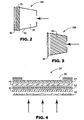
- FIGS. 2 and 3 are cross-sectional side views of exemplary embodiments of a first conditioner according to the invention.
- FIG. 4 is a cross-sectional side view of an exemplary second conditioner according to the invention.
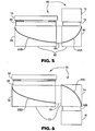
- FIGS. 5 and 6 are cross sectional side views of additional embodiments of transmissive display systems according to the invention.
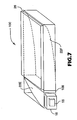
- FIG. 7 is a perspective view of yet another embodiment of a
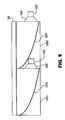
backlight assembly 100 for use in a transmissive display system. - FIGS. 8 and 9 are cross-sectional side views of backlight assemblies that utilize more than one light chamber.
- FIG. 10 is a flow diagram illustrating an example process of illuminating a display according to an embodiment of the invention.
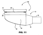
- FIG. 11 is a cross-sectional side view of another transmissive display system according to the invention.
- FIG. 1 is a cross-sectional side view of a
transmissive display system 10 according to the invention.System 10 includes abacklight assembly 12 and atransmissive display 14.Transmissive display 14, for example, may be coupled to a video board (not shown) to receive input signals that define images to be displayed.Backlight assembly 12 provides light thattransmissive display 14 alters according to the input signals to produce visual representations of the images. For example,transmissive display 14 may be a light valve such as a liquid crystal display ("LCD"), or any other transmissive display that requires illumination from a light source. -
Backlight assembly 12 includes alight source 16 that comprises, for example, one or more point-like light sources such as light emitting diodes ("LEDs"). Alternatively,light source 16 may comprise any light producing apparatus, including a fluorescent lamp or the like. Fluorescent lamps, however, are relatively bulky and electrically noisy, and can use significant amounts of energy. For this reason, semiconductor light sources such as LEDs are generally preferred. In comparison, semiconductor light sources require a relatively small amount of energy and can be used in place of other light sources to significantly reduce the size ofbacklight assembly 12. By way of example,light source 16 may comprise a three color LED such as model NSCM310, available from Nichia Corporation of Japan, or a white LED such as model NSCW100, also available from Nichia Corporation of Japan. In some embodiments,light source 16 represents a number of LEDs that collectively produce the desired light. -
Backlight assembly 12 may also include afirst conditioner 18, i.e. a pre-conditioner. For example,first conditioner 18 may alter the polarization, spatial uniformity, angular distribution, and/or the color of the light emitted fromlight source 16. In this manner, the light emitted fromlight source 16 can be adapted for use in illumination oftransmissive display 14. Several particularly effective embodiments offirst conditioner 18 are described in greater detail below. - Light that passes through the
first conditioner 18 enterslight chamber 20.Reflector 22 resides withinlight chamber 20 to reflect the light that was conditioned byfirst conditioner 18.Light chamber 20 may be hollow (except for reflector 22) or may be filled with a filler material such as solid glass or plastic. For example, filler material could be used to condition light in lieu ofconditioner 18. One or more of the walls oflight chamber 20 may be reflective. - Light that reflects off
reflector 22 is directed towardssecond conditioner 26, i.e., a post conditioner. Specific embodiments ofsecond conditioner 26 are outlined in greater detail below. Briefly, thesecond conditioner 26 further conditions the light just before it is used to illuminatetransmissive display 14. The second conditioner may also filter or reflect undesirable light. Anaperture 28 may be formed around the outer surface ofsecond conditioner 26. Light that is conditioned bysecond conditioner 26 can then pass throughaperture 28 to illuminatetransmissive display 14. -
Reflector 22 can be viewed as dividinglight chamber 20 into aninner portion 24 and anouter portion 25. The inner andouter portions portions reflector 22 is only partially reflective. In that case, light that passes throughreflector 22 may reflect off the walls ofouter portion 25 or off of a diffusant filler material withinouter portion 25 before re-enteringinner portion 24 throughreflector 22. In this manner, light can be diffused and recycled withinlight chamber 20 until it is conditioned for use as an effective illuminator oftransmissive display 14. -
Reflector 22 may include a highly or partially reflecting coating deposited onto shaped surfaces that define the inner orouter portions light chamber 20. Alternatively,reflector 22 may comprise a reflective film made by coating a suitable film substrate.Reflector 22 may also comprise a polymer multi-layer optical film ("MOF") having high reflectivity or partial reflectivity in the spectral range desired. For example,reflector 22 may be a reflective MOF that reflects over the entire visible wavelength range of 400 nm to 700 nm while transmitting infrared light, or a colored-mirror MOF that reflects a narrower spectral range as desired. In either case, the reflective MOF can provide advantages to thetransmissive display system 10 by reflecting only the light having desirable wavelengths towards thetransmissive display 14. -
Reflector 22 can also be a polymer MOF reflective polarizer that reflects light having substantially one type of polarization. For example, it may reflect light having a first linear polarization and transmit light having orthogonal linear polarization, or it may reflect light having a first circularly polarization and transmit light having the opposite circular polarization. An example of a linear reflector polarizer is Dual Brightness Enhancing Film ("DBEF") available from Minnesota Mining and Manufacturing Company of Saint Paul, Minnesota. An example of a reflective circular polarizer is a cholesteric film, such as Nipocs™ film available from Nitto-Denko of Japan. Polarized reflective films can be used, for example, to polarize the light that enterslight chamber 20, or to augment other polarizers used inbacklight assembly 12. This can enhance the effectiveness ofdisplay system 10 iftransmissive display 14 is a display that requires polarized light. -
Reflector 22 can be a specular reflector such as a smooth specular reflective film. The specular reflective film can serve to reverse circular polarization of light upon reflection, orreflector 22 may be a quarter-wave mirror that serves to rotate linear polarization. Such polarization reversals upon reflection can be useful in polarization recycling schemes that utilize reflective polarizers, like some embodiments described below. Specular reflective films provide improved light control compared to patterned reflective surfaces or molded plastic chambers often used in conventional backlight assemblies. In addition, specular reflective films are generally more efficient at directing light than patterned reflective surfaces or molded plastic chambers. - The surface texture of
reflector 22 is generally smooth to improve spatial uniformity of the illumination oftransmissive display 14. The shape ofreflector 22 may be used to maximize the brightness of the final backlight output. For example,reflector 22 may be curved in such a way as to focus light fromfirst conditioner 12 tosecond conditioner 26. Alternatively or additionally,reflector 22 may improve uniformity of the final backlight output. The curvature can be made parabolic or dome shaped. For example, a specular reflective film may be parabolically curved along the surface ofinner portion 24 orouter portion 25 if one or both of the portions are filled with a filler material. -
Reflector 22 can also be pre-formed, for example, prior to insertion inlight chamber 20. An injection molding process, a cast and cure process, or a combination of an injection molding process and a cast and cure process could be used to formreflector 22. In either case,reflector 22 may comprise a reflective coating on an appropriately shaped plastic surface, or may comprise a thermoformed mirror film. The creation ofreflector 22 can be simplified ifreflector 22 does not require a patterned surface. - The
transmissive display system 10 provides several advantages over conventional arrangements. In particular, the light chamber design allowsbacklight assembly 12 to have a relatively compact size. If desired, the use of light guides and/or bulky fluorescent lamps can be avoided. Moreover,reflector 22 may be a specular reflector to provide advantages of efficiency and control over conventional patterned reflectors or non-specular molded plastic chambers. In addition,first conditioner 18 andsecond conditioner 26 can be fabricated prior to assembly of thebacklight assembly 12 to further reduce manufacturing costs. Importantly, thebacklight assembly 12 can effectively condition light for use in illumination oftransmissive display 14. Light that is not properly conditioned may be filtered or possibly recycled inlight chamber 20 to more efficiently utilizelight source 16. - FIGS. 2-3 are cross-sectional side views of exemplary embodiments of a
first conditioner 18. As shown in FIG. 2,housing 32 offirst conditioner 18A forms acavity 34.Cavity 34 may have a horn-shaped configuration, wherein the cross-sectional diameter ofcavity 34 becomes larger in the direction that light propagates.Cavity 34 is formed with a hole, through which light can enter from a light source (as indicated by the arrow). The inner side walls ofcavity 34 may be reflective so that light entering the cavity at large angles can reflect or scatter off the inner side walls to propagate throughfirst conditioner 18A. Adiffuser film 36 may reside on the larger side ofcavity 34.Diffuser film 36 diffuses incoming light so that the light that exitsfirst conditioner 18A is more spatially uniform in intensity. In other words, light that enterscavity 34 may come from one or more point sources, and therefore light directed towarddiffuser film 36 may be much more intense at particular locations on an entrance face ofdiffuser film 36. Light that exitsdiffuser film 36, however, may be more spatially uniform in intensity over the exit surface ofdiffuser film 36. This, in turn, can improve spatial uniformity of light that ultimately illuminates transmissive display 14 (FIG. 1). -
Diffuser film 36 may comprise a surface diffuser or a diffusive coating on a carrier film. Alternatively, a bulk diffuser without a substrate could be used to realizediffuser film 36. In another example, a thin section of white molded plastic could be used. The combination ofcavity 24 anddiffuser film 36 can serve to direct light out offirst conditioner 18A such that the light is substantially uniform intensity over the surface area of thediffuser film 36. By way of example, a suitable diffuser film could be created by roughening the surface of an otherwise clear film. Alternatively, a coating including a resin and scattering particles could be applied to a clear film and then cured to realize a suitable diffuser film. - In some embodiments, a
Fresnel lens 38 can be positioned adjacent todiffuser film 36.Fresnel lens 38 provides a relatively compact way to reduce the angular distribution of light entering the light chamber 20 (FIG. 1).Fresnel lens 38 may comprise a separate piece of molded plastic, or may form a molded portion of an edge oflight chamber 20. Alternatively,Fresnel lens 38 may form a molded portion of an edge offirst conditioner 18A.Fresnel lens 38 may have a linear, circular, or elliptical groove structure. In any case, the presence ofFresnel lens 38 can ultimately improve the illumination effect ontransmissive display 14. As an alternative toFresnel lens 38, a holographic optical element ("HOE") could be used. - FIG. 3 illustrates another embodiment of a
first conditioner 18. In FIG. 3,first conditioner 18B includes a cavity that is filled withdiffuser material 42. Diffuser material diffuses incoming light so that the light that exitsfirst conditioner 18B is more uniform in intensity. A suitable diffuser material could be created, for example, by combining a resin with scattering particles and injecting the mixture into the cavity offirst conditioner 18B. The mixture can then be cured. Examples of scattering particles include titanium dioxide or transparent materials having an index of refraction different from that of the cured resin. - Filling the cavity with diffuser material may improve the diffusion of light compared to the embodiment in FIG. 2. However, filling the cavity with diffuser material can be more difficult and costly than using a diffuser film. In some embodiments, the cavity can be filled with diffuser material and a diffuser film can be used as well. Again,
Fresnel lens 38 may also be used to reduce the angular distribution of light entering the light chamber 20 (FIG. 1). A polarizer film (not shown) could also be used to properly polarize the light enteringlight chamber 20. An example of a suitable polarizer film is HLC25618S film available from Sanritz of Japan. - In still other embodiments,
first conditioner 18 includes a film or coating that converts light having a first wavelength to light having a second wavelength. For example,light source 16 may emit ultra-violet ("UV") light. In that case,first conditioner 18 may include a film, coating or filler material including fluorescent materials that convert UV light to light within the visible spectrum. - FIG. 4 is a cross-sectional side view of one particular embodiment of a
second conditioner 26.Second conditioner 26 may include a variety of films or molded optical components so that light that emerges fromsecond conditioner 26 has the required spectral content, adequate light distribution and the required polarization state. For example,second conditioner 26 may includeFresnel lens 46 to collimate incoming light (indicated by the arrows). -
Second conditioner 26 may also include areflective polarizer 48.Reflective polarizer 48 may act as a brightness enhancing component by reflecting light of undesired polarization back into the light chamber for recycling. In other words,reflective polarizer 48 may only allow light that is polarized correctly to pass through. Light having undesired polarization is reflected. The light reflected from thereflective polarizer 48 may reenter the light chamber, possibly becoming polarized correctly and then later passed throughreflective polarizer 48. In this manner, light from thelight source 16 can be used more efficiently. An example of a suitable reflective polarizer is DBEF, available from Minnesota Mining and Manufacturing Company of Saint Paul, Minnesota. -
Second conditioner 26 may also include one or moreprismatic films 52 that serve to decrease the angular distribution of light exitinglight chamber 20. For example,prismatic film 52 may redirect light exitinglight chamber 20 at particular angles relative to theprismatic film 52. The light redirected byprismatic film 52 can also be recycled, eventually exitinglight chamber 20 at an angle which will pass throughprismatic film 52. For example, Brightness Enhancing Film ("BEF"), available from Minnesota Mining and Manufacturing Company of Saint Paul, Minnesota could be used to realizeprismatic film 52. Alternatively,prismatic film 52 may comprise TRAF, available from Minnesota Mining and Manufacturing Company of Saint Paul Minnesota. TRAF redirects light coming in at high angles to exit at different angles. - In some embodiments, more than one
prismatic film 52 could be positioned adjacent one another, but rotated 90 degrees relative to one another. In that case, the two prismatic films may collectively comprise what is referred to as a "crossed prismatic film." -
Second conditioner 26 may also include adiffuser film 50 and apolarizer film 54.Diffuser film 50 can improve spatial uniformity of light. In addition, the diffuser film may be colored so as to filter undesired wavelengths of light. Alternatively, a separate color filter (not shown) could be used to ensure the desired spectral output.Polarizer film 54 absorbs or reflects light having undesired polarization and transmits light of the desired polarization. Anaperture 56 can also be added to block stray light that might degrade optical quality of the light exitingsecond conditioner 26. Examples of a suitable diffuser film and a suitable polarizer film are mentioned above. - The components of
second conditioner 26 may be arranged in various orders. However,second conditioner 26 may operate most effectively when the components are arranged as illustrated in FIG. 4. For example, light may pass throughFresnel lens 46, thendiffuser film 50, thenprismatic film 52, thenreflective polarizer 48, then polarizer 54 before finally passing throughaperture 56. - Referring again to FIG. 1, additional features could also be included one or more of the various components to facilitate connections between the components. For example,
second conditioner 26 may include a tapered frame and clips, or the like, for mating with a housing oftransmissive display 14. Similarly,first conditioner 18 may include features to facilitate mating withlight source 16. For example, mechanical elements could facilitate the mating, or alternatively, an adhesive or a bonding material could be used. - FIG. 5 is a cross-sectional side view of another embodiment of a
transmissive display system 60 according to the invention. In this embodiment, alight chamber 62 includes two separatelight chamber regions third conditioner 68 may be positioned between the twolight chamber regions light source 16 to be positioned on the same side oflight chamber 62 as thesecond conditioner 26. In other words, in thetransmissive display system 60,light source 16 is positioned along a common side withtransmissive display 14. By positioningtransmissive display 14 and thelight source 16 along a common side oflight chamber 62,transmissive display 14 andlight source 16 can be directly coupled to a main circuit board without the need for additional flex circuits often used in conventional transmissive display systems. In other words, thelight source 16 andtransmissive display 14 could be directly coupled to the main circuit board. However, the main circuit board may need to be formed with a hole for viewing oftransmissive display 16. - In operation, light from
light source 16 is conditioned as it passes throughfirst conditioner 18. The light then reflects offreflector 22A, which has a shape that causes light to reflect towardthird conditioner 68. The light passes throughthird conditioner 68 and reflects offreflector 22B, which has a shape that causes light to reflect towardsecond conditioner 26. The light then passes throughsecond conditioner 26 and illuminatestransmissive display 14.Reflectors first conditioner 18 may be similar to that illustrated in FIGS. 2 or 3, andsecond conditioner 26 may be similar to that illustrated in FIG. 4.Third conditioner 68 may include one or more optical elements such as a diffuser film or a polarizer film that further condition the light according to the desired characteristics. A suitable polarizer film and a suitable diffuser film are listed above. - In one embodiment related to FIG. 5,
reflector 22A andreflector 22B include a single reflective film. In that case, the reflective film could be reflective polarizer or a mirror film formed to define bothreflector 22A andreflector 22B. - FIG. 6 is a cross-sectional side view of another embodiment of a
transmissive display system 70 according to the invention. In this embodiment, alight chamber 72 again includes two separatelight chamber regions third conditioner 78 may be positioned between the twolight chamber regions light source 16 to be positioned on the opposite side oflight chamber 72 in relation to thesecond conditioner 26. In other words, in thetransmissive display system 70,light source 16 is positioned on the opposite side oflight chamber 72 in relation totransmissive display 14. Positioning thetransmissive display 14 and thelight source 16 along opposing sides oflight chamber 62 can provide advantages. For example, the need for additional flex circuits often used in conventional transmissive display systems to couplelight source 16 to a main circuit board can be avoided. In contrast to conventional arrangements, the embodiment of FIG. 6 allowslight source 16 to be coupled directly to the main circuit board. Onlytransmissive display 14 would require a flex circuit. As an advantage over the embodiment of FIG. 5,transmissive display 14 could be viewed without forming any additional holes on the circuit board. - In operation, light from
light source 16 is conditioned as it passes throughfirst conditioner 18. The light then reflects offreflector 22C which has a shape that causes light to reflect towardthird conditioner 78. The light passes throughthird conditioner 78 and reflects offreflector 22D, which has a shape that causes light to reflect towardsecond conditioner 26. The light then passes throughsecond conditioner 26 and illuminatestransmissive display 14. Again,reflectors first conditioner 18 may be similar to that illustrated in FIGS. 2 or 3, andsecond conditioner 26 may be similar to that illustrated in FIG. 4.Third conditioner 78 may include one or more optical components such as a diffuser film or a polarizer film that further condition the light according to the desired characteristics. - In one embodiment related to FIG. 6,
reflector 22C andreflector 22D include a single reflective film. In that case, the reflective film would need to be a reflective polarizer. The single reflective film would also comprise an element ofthird conditioner 78. The reflective film could be formed to define bothreflector 22C andreflector 22D, bending throughthird conditioner 78. The transmission axis of the reflective polarizer would preferably be 45 degrees relative to an edge of the chamber to ensure that light reflected offreflector 22C would pass throughthird conditioner 78. - FIG. 7 is a perspective view of yet another embodiment of a
backlight assembly 100 for use in a transmissive display system. As shown,backlight assembly 100 includeslight source 16 that passes light throughfirst conditioner 18. The light then reflects offreflector 22E which has a shape that causes light to reflect towardthird conditioner 108. The light passes throughthird conditioner 108 and reflects offreflector 22F, which has a shape that causes light to reflect towardsecond conditioner 26. The light then passes throughsecond conditioner 26. A transmissive display (not shown) can be positioned adjacentsecond conditioner 26 to be illuminated. The arrangement illustrated in FIG. 7 can provide space advantages for some compact display systems. - FIGS. 8 and 9 are cross-sectional side views of backlight assemblies that utilize more than one light chamber. These embodiments utilize the teaching above in combination to realize a backlighting system that has an increased lighting area for the transmissive display. For example, as shown in FIG. 8,
light sources first conditioners light chambers reflectors second conditioner 26. A transmissive display (not shown) can be positioned adjacentsecond conditioner 26 to be illuminated.Second conditioner 26 may further include a top diffuser film, i.e., an additional diffuser film comprising the outermost layer ofsecond conditioner 26, to achieve uniform illumination along the joining line oflight chambers - FIG. 9 illustrates another example. In FIG. 9
light sources first conditioners light chambers reflectors second conditioner 26. Again, a transmissive display can be positioned adjacentsecond conditioner 26 to be illuminated, andsecond conditioner 26 may further include a top diffuser film to achieve uniform illumination along the joining line oflight chambers - The embodiments in FIGS. 8 and 9 can provide the advantage of increasing the lighting area for the transmissive display. The use of relatively bulky components, however, can still be avoided, allowing the system to maintain a relatively compact form factor in relation to the size of the lighting area. Additional light sources and light chambers could be combined according to the invention to realize larger and larger lighting areas.
- FIG. 10 is a flow diagram illustrating a process of illuminating a display according to the invention. As shown, a light source provides light (112), which is then conditioned by a first conditioner (114). A second conditioner then reflects (116) and conditions the light (118). A display can then be effectively illuminated with the light (120). The first and second conditioners may substantially correspond to those described above. Similarly, the reflector may substantially correspond to one of the reflectors described above. For example, the reflector could also be used to condition the light. An additional third conditioner and second reflector could also be used as shown in FIGS. 5 or 6.
- FIG. 11 is a cross-sectional side view of a
transmissive display system 130 according to yet another embodiment of the invention. In particular,transmissive display system 130 is substantially similar tosystem 10 illustrated in FIG. 1. However,transmissive display system 130 eliminates the outer portion 25 (FIG. 1) of the light chamber. Instead,inner portion 24 comprises the light chamber without an outer portion. - The invention can provide several advantages. For example, the invention can be used to reduce the size of backlight assemblies. This is particularly advantageous for use with miniature displays, i.e., those having a diagonal dimension less than 3 centimeters. Such displays are often implemented in viewfinders for digital cameras and video cameras, or on head mounted video displays or the like. The invention achieves a relatively compact form factor by removing the need to use bulky conventional components.
- For example, the light chamber configured according to the invention removes the need to use flat light guides that are typically illuminated by fluorescent lamps. Fluorescent lamps typically require a large amount of power and specialized high voltage drivers, which may introduce electrical noise. The invention, however, does not require these costly and bulky components. Instead, efficient "point-like" light sources, such as light emitting diodes, can be used instead of light guides and fluorescent lamps. Thus, the need for a fluorescent driver circuit is also eliminated.
- The invention can utilize a smooth specular reflector within the light chamber to reflect light. Smooth specular reflectors can improve the efficiency of the backlighting system compared to patterned reflectors or non-specular molded plastic chambers. Moreover, smooth specular reflectors can provide better light control than patterned reflectors or non-specular molded plastic chambers.
- The invention provides an efficient and effective assembly for distributing light from discrete point-like light sources to illuminate a transmissive display with the required spatial uniformity of brightness and color. Moreover, in some embodiments, the invention can remove the need for costly connectors, such as flex circuits, that connect the display to a main circuit board. By positioning the display and the light source along a common side of the light chamber, or on opposing sides of the light chamber, the display can be directly coupled to a main circuit board without the need for additional flex circuits. Another advantage relates to the cost of manufacturing and assembly, which can be significantly reduced by various aspects of the invention.
- Various embodiments of the invention have been described. For instance, a backlight assembly has been described for use in a transmissive display system. Nevertheless, various modifications may be made without departing from the scope of the invention. Accordingly, other embodiments are within the scope of the following claims.
Claims (25)
- A backlight assembly (12) for a transmissive display device comprising:a light chamber (20);a light source (16) that is arranged to emit light into the light chamber (20) ;a first conditioner (18) disposed between the light source (16) and the light chamber (20),
wherein the first conditioner (18) is arranged to alter light entering the light chamber (20) ;a reflector (22) within the light chamber (20) that is arranged to reflect light altered by the first conditioner (18); anda second conditioner (26) that is arranged to alter light reflected by the reflector (22) wherein the light chamber is arranged such that light exits the light chamber (20) through the second conditioner (26),
characterized in that the first conditioner (18) includes a horn shaped cavity formed with a hole on a first side of the cavity, such that light from the light source enters the cavity through the hole and in that the reflector (22) comprises a specular reflector curved to focus light from the first conditioner (18) to the second conditioner (26). - The backlight assembly of claim 1, wherein the light source (16) comprises at least one light emitting diode.
- The backlight assembly of claim 2, wherein the light source (16) comprises a number of light emitting diodes.
- The backlight assembly of claim 1, wherein the first conditioner (18) includes a diffuser film.
- The backlight assembly of any of claims 1 to 4, wherein inner walls of the cavity are reflective.
- The backlight assembly of any of claims 1 to 4, further comprising a diffuser film (36) positioned on a second side of the cavity, wherein the second side is opposite the first side.
- The backlight assembly of claim 6, further comprising a Fresnel lens (38) adjacent the diffuser film (36).
- The backlight assembly of any of claims 1 to 4, wherein the cavity is filled with a diffuser material (42).
- The backlight assembly of claim 1, wherein the chamber (20) is filled with diffuser material.
- The backlight assembly of claim 1, wherein inner walls of the chamber (20) are reflective.
- The backlight assembly of claim 1, wherein the reflector (22) comprises a specular reflective film.
- The backlight assembly of claim 1, wherein the reflector (22) is a reflective polarizer.
- The backlight assembly of claim 1, wherein the reflector (22) comprises a specular reflective coating.
- The backlight assembly of claim 1, wherein the reflector (22) has a substantially smooth surface.
- The backlight assembly of claim 1, wherein the second conditioner (26) includes a Fresnellens.
- The backlight assembly of claim 1, wherein the second conditioner (26) includes a reflective polarizer to reflect light having undesired polarization back into the chamber.
- The backlight assembly of claim 1, wherein the second conditioner (26) includes at least one prismatic film.
- The backlight assembly of claim 1, wherein the second conditioner (26) includes a diffuser film.
- The backlight assembly of claim 1, wherein the second conditioner (26) includes a polarizer film.
- The backlight assembly of claim 1, wherein the chamber (20) is divided into two chamber regions separated by a third conditioner (68; 78).
- The backlight assembly of claim 20, wherein the third conditioner (68; 78) includes a diffuser film.
- The backlight assembly of claim 20, wherein the third conditioner (68;78) includes a polarizer film,
- The backlight assembly of claim 20, further comprising a second reflector, wherein the reflectors reside respectively within the two chamber regions.
- The backlight assembly of claim 20, wherein the light source (16) and the second conditioner are positioned on a same side of the chamber (20).
- The backlight assembly of claim 20, wherein the light source (16) and the second conditioner are positioned on opposing sides of the chamber (20).
Applications Claiming Priority (3)
| Application Number | Priority Date | Filing Date | Title |
|---|---|---|---|
| US949948 | 2001-09-10 | ||
| US09/949,948 US6663262B2 (en) | 2001-09-10 | 2001-09-10 | Backlighting transmissive displays |
| PCT/US2002/024510 WO2003023277A1 (en) | 2001-09-10 | 2002-07-31 | Backlighting transmissive displays |
Publications (2)
| Publication Number | Publication Date |
|---|---|
| EP1425538A1 EP1425538A1 (en) | 2004-06-09 |
| EP1425538B1 true EP1425538B1 (en) | 2007-12-19 |
Family
ID=25489722
Family Applications (1)
| Application Number | Title | Priority Date | Filing Date |
|---|---|---|---|
| EP02750394A Expired - Lifetime EP1425538B1 (en) | 2001-09-10 | 2002-07-31 | Backlighting transmissive displays |
Country Status (9)
| Country | Link |
|---|---|
| US (2) | US6663262B2 (en) |
| EP (1) | EP1425538B1 (en) |
| JP (1) | JP4331602B2 (en) |
| KR (1) | KR100860890B1 (en) |
| CN (1) | CN100422820C (en) |
| AT (1) | ATE381723T1 (en) |
| DE (1) | DE60224206T2 (en) |
| TW (1) | TWI274205B (en) |
| WO (1) | WO2003023277A1 (en) |
Families Citing this family (97)
| Publication number | Priority date | Publication date | Assignee | Title |
|---|---|---|---|---|
| US5910854A (en) * | 1993-02-26 | 1999-06-08 | Donnelly Corporation | Electrochromic polymeric solid films, manufacturing electrochromic devices using such solid films, and processes for making such solid films and devices |
| US5668663A (en) | 1994-05-05 | 1997-09-16 | Donnelly Corporation | Electrochromic mirrors and devices |
| US6891563B2 (en) | 1996-05-22 | 2005-05-10 | Donnelly Corporation | Vehicular vision system |
| US6326613B1 (en) | 1998-01-07 | 2001-12-04 | Donnelly Corporation | Vehicle interior mirror assembly adapted for containing a rain sensor |
| US6124886A (en) | 1997-08-25 | 2000-09-26 | Donnelly Corporation | Modular rearview mirror assembly |
| US6172613B1 (en) | 1998-02-18 | 2001-01-09 | Donnelly Corporation | Rearview mirror assembly incorporating vehicle information display |
| US8294975B2 (en) | 1997-08-25 | 2012-10-23 | Donnelly Corporation | Automotive rearview mirror assembly |
| US6445287B1 (en) | 2000-02-28 | 2002-09-03 | Donnelly Corporation | Tire inflation assistance monitoring system |
| US8288711B2 (en) | 1998-01-07 | 2012-10-16 | Donnelly Corporation | Interior rearview mirror system with forwardly-viewing camera and a control |
| US6329925B1 (en) | 1999-11-24 | 2001-12-11 | Donnelly Corporation | Rearview mirror assembly with added feature modular display |
| US6477464B2 (en) | 2000-03-09 | 2002-11-05 | Donnelly Corporation | Complete mirror-based global-positioning system (GPS) navigation solution |
| US6693517B2 (en) | 2000-04-21 | 2004-02-17 | Donnelly Corporation | Vehicle mirror assembly communicating wirelessly with vehicle accessories and occupants |
| AU2001243285A1 (en) | 2000-03-02 | 2001-09-12 | Donnelly Corporation | Video mirror systems incorporating an accessory module |
| US7370983B2 (en) | 2000-03-02 | 2008-05-13 | Donnelly Corporation | Interior mirror assembly with display |
| US7167796B2 (en) | 2000-03-09 | 2007-01-23 | Donnelly Corporation | Vehicle navigation system for use with a telematics system |
| WO2007053710A2 (en) | 2005-11-01 | 2007-05-10 | Donnelly Corporation | Interior rearview mirror with display |
| US7581859B2 (en) | 2005-09-14 | 2009-09-01 | Donnelly Corp. | Display device for exterior rearview mirror |
| US7255451B2 (en) | 2002-09-20 | 2007-08-14 | Donnelly Corporation | Electro-optic mirror cell |
| EP1363810B1 (en) * | 2001-01-23 | 2007-05-30 | Donnelly Corporation | Improved vehicular lighting system |
| US6948840B2 (en) * | 2001-11-16 | 2005-09-27 | Everbrite, Llc | Light emitting diode light bar |
| US6918674B2 (en) | 2002-05-03 | 2005-07-19 | Donnelly Corporation | Vehicle rearview mirror system |
| EP1514246A4 (en) | 2002-06-06 | 2008-04-16 | Donnelly Corp | Interior rearview mirror system with compass |
| US7329013B2 (en) | 2002-06-06 | 2008-02-12 | Donnelly Corporation | Interior rearview mirror system with compass |
| EP1543358A2 (en) | 2002-09-20 | 2005-06-22 | Donnelly Corporation | Mirror reflective element assembly |
| US7310177B2 (en) | 2002-09-20 | 2007-12-18 | Donnelly Corporation | Electro-optic reflective element assembly |
| US6886954B2 (en) * | 2002-12-23 | 2005-05-03 | Intel Corporation | System and method for processing light in an electronic display system |
| US20040207774A1 (en) * | 2003-04-17 | 2004-10-21 | Gothard David L. | Illumination apparatus for LCD/organic displays |
| US7289037B2 (en) | 2003-05-19 | 2007-10-30 | Donnelly Corporation | Mirror assembly for vehicle |
| US7557876B2 (en) | 2003-07-25 | 2009-07-07 | Nitto Denko Corporation | Anisotropic fluorescent thin crystal film and backlight system and liquid crystal display incorporating the same |
| US7446924B2 (en) | 2003-10-02 | 2008-11-04 | Donnelly Corporation | Mirror reflective element assembly including electronic component |
| US7308341B2 (en) | 2003-10-14 | 2007-12-11 | Donnelly Corporation | Vehicle communication system |
| US7223005B2 (en) * | 2003-12-23 | 2007-05-29 | Lamb David J | Hybrid lightguide backlight |
| US7303322B2 (en) * | 2003-12-23 | 2007-12-04 | 3M Innovative Properties Company | Multiple lightguide backlight |
| US7213939B2 (en) | 2004-03-02 | 2007-05-08 | Hewlett-Packard Development Company, L.P. | Hue adjusting lighting system |
| US7450194B2 (en) | 2004-03-04 | 2008-11-11 | Nitto Denko Corporation | Polarized interference recycling backlight module and liquid crystal display incorporating the same |
| US7733443B2 (en) | 2004-03-09 | 2010-06-08 | Nitto Denko Corporation | LCD comprising backlight and reflective polarizer on front panel |
| US7456915B2 (en) | 2004-03-26 | 2008-11-25 | Nitto Denko Corporation | Liquid crystal display panel with broadband interference polarizers |
| TWI293135B (en) * | 2004-06-08 | 2008-02-01 | Prodisc Technology Inc | Liquid crystal display and backlight module |
| TWI293707B (en) * | 2004-06-08 | 2008-02-21 | Prodisc Technology Inc | Liquid crystal display and backlight module |
| JP4746301B2 (en) * | 2004-10-01 | 2011-08-10 | ライツ・アドバンスト・テクノロジー株式会社 | Backlight unit |
| DE202005016373U1 (en) * | 2004-11-09 | 2005-12-29 | Element Displays Dr. Wiemer Gmbh | Liquid crystal display device, has liquid crystal layer, polarization filter and dispersion layer or retro reflection layer that are arranged under intermediate joint of layers, and housing translucently designed in rear side of device |
| CN100395616C (en) * | 2004-12-11 | 2008-06-18 | 鸿富锦精密工业(深圳)有限公司 | Focusing lens and back light module adopting focusing lens |
| GB0427607D0 (en) * | 2004-12-16 | 2005-01-19 | Microsharp Corp Ltd | Structured optical film |
| US7559664B1 (en) | 2004-12-27 | 2009-07-14 | John V. Walleman | Low profile backlighting using LEDs |
| CN100406993C (en) * | 2005-02-01 | 2008-07-30 | 精碟科技股份有限公司 | Liquid crystal display device and its backlight module |
| EP1883855B1 (en) | 2005-05-16 | 2011-07-20 | Donnelly Corporation | Vehicle mirror assembly with indicia at reflective element |
| KR20060120373A (en) * | 2005-05-19 | 2006-11-27 | 삼성전자주식회사 | Back light unit and liquid crystal display apparatus employing the same |
| US20070081361A1 (en) * | 2005-10-12 | 2007-04-12 | Donald Clary | Light emitting diode backlight for liquid crystal displays |
| KR100699487B1 (en) * | 2005-10-18 | 2007-03-26 | 엘지전자 주식회사 | Light-providing section and backlight unit including the same |
| TWI331694B (en) * | 2005-10-20 | 2010-10-11 | Ind Tech Res Inst | Back-lighted structure |
| DE102005057166A1 (en) * | 2005-11-30 | 2007-05-31 | BSH Bosch und Siemens Hausgeräte GmbH | Display element for electrical appliance has light emitting diodes, beam path of light in display element that passes at least two light-scattering elements |
| EP2049365B1 (en) * | 2006-08-01 | 2017-12-13 | 3M Innovative Properties Company | Illumination device |
| KR100829015B1 (en) * | 2006-08-22 | 2008-05-14 | 엘지전자 주식회사 | Surface light source, back light unit and liquid crystal display having the same |
| EP2067065B1 (en) * | 2006-09-19 | 2017-05-31 | Philips Lighting Holding B.V. | Illumination system, luminaire and display device |
| US7548677B2 (en) * | 2006-10-12 | 2009-06-16 | Microsoft Corporation | Interactive display using planar radiation guide |
| CN101529156B (en) * | 2006-10-16 | 2012-03-21 | 皇家飞利浦电子股份有限公司 | Lighting device |
| WO2008144644A2 (en) | 2007-05-20 | 2008-11-27 | 3M Innovative Properties Company | Semi-specular components in hollow cavity light recycling backlights |
| CN101681057B (en) | 2007-05-20 | 2012-07-04 | 3M创新有限公司 | Thin hollow backlights with beneficial design characteristics |
| JP5336475B2 (en) | 2007-05-20 | 2013-11-06 | スリーエム イノベイティブ プロパティズ カンパニー | Optical recycling hollow cavity type display backlight |
| WO2008144650A1 (en) | 2007-05-20 | 2008-11-27 | 3M Innovative Properties Company | Collimating light injectors for edge-lit backlights |
| JP5580193B2 (en) * | 2007-06-14 | 2014-08-27 | コーニンクレッカ フィリップス エヌ ヴェ | LED-based lighting fixture with adjustable beam shape |
| TWM327550U (en) * | 2007-09-13 | 2008-02-21 | Kun Dian Photoelectric Entpr Co | LED lamp structure with light-guiding plate |
| JP2009099271A (en) * | 2007-10-12 | 2009-05-07 | Harison Toshiba Lighting Corp | Hollow surface lighting device |
| US8848132B2 (en) | 2008-02-07 | 2014-09-30 | 3M Innovative Properties Company | Hollow backlight with structured films |
| JP5792464B2 (en) | 2008-02-22 | 2015-10-14 | スリーエム イノベイティブ プロパティズ カンパニー | BACKLIGHT HAVING SELECTIVE OUTPUT LIGHT DISTRIBUTION, DISPLAY SYSTEM USING SAME, AND METHOD FOR FORMING BACKLIGHT |
| US8177382B2 (en) * | 2008-03-11 | 2012-05-15 | Cree, Inc. | Apparatus and methods for multiplanar optical diffusers and display panels for using the same |
| US8154418B2 (en) | 2008-03-31 | 2012-04-10 | Magna Mirrors Of America, Inc. | Interior rearview mirror system |
| FR2931748B1 (en) * | 2008-05-29 | 2010-12-10 | Faurecia Interieur Ind | INTERIOR LIGHTING ELEMENT, DOOR AND MOTOR VEHICLE CORRESPONDING. |
| WO2009149010A1 (en) | 2008-06-04 | 2009-12-10 | 3M Innovative Properties Company | Hollow backlight with tilted light source |
| US8206012B2 (en) * | 2008-06-30 | 2012-06-26 | Production Resource Group, Llc | Layered dimmer system |
| CN102216124B (en) * | 2008-10-02 | 2014-06-25 | 佛吉亚汽车内部设备工业公司 | Interior trim assembly for a motor vehicle and motor vehicle |
| US9487144B2 (en) | 2008-10-16 | 2016-11-08 | Magna Mirrors Of America, Inc. | Interior mirror assembly with display |
| KR101040769B1 (en) * | 2008-10-23 | 2011-06-10 | 김중철 | breaker for crosswalk |
| WO2010049759A1 (en) * | 2008-10-30 | 2010-05-06 | Faurecia Interieur Industrie | Process for manufacturing an automobile interior trim part with an airbag cover, and to the associated machine |
| KR101383930B1 (en) * | 2008-12-24 | 2014-04-10 | 엘지디스플레이 주식회사 | Light irradiation apparatus |
| JP5261245B2 (en) * | 2009-03-26 | 2013-08-14 | 株式会社ジャパンディスプレイウェスト | Backlight and display imaging device |
| BRPI1012268A2 (en) * | 2009-06-30 | 2016-04-05 | Sharp Kk | lighting device, display device and television receiver. |
| KR101649695B1 (en) * | 2009-08-04 | 2016-08-22 | 엘지디스플레이 주식회사 | Liquid crystal device and method for designing liquid crystal display device |
| CN102483544B (en) | 2009-09-11 | 2015-08-12 | 杜比实验室特许公司 | There is the display of the backlight being incorporated with reflection horizon |
| US20110193872A1 (en) * | 2010-02-09 | 2011-08-11 | 3M Innovative Properties Company | Control system for hybrid daylight-coupled backlights for sunlight viewable displays |
| EP2450612B1 (en) * | 2010-11-08 | 2014-04-30 | LG Innotek Co., Ltd. | Lighting apparatus |
| JP5406225B2 (en) | 2010-12-06 | 2014-02-05 | エルジー イノテック カンパニー リミテッド | Backlight unit |
| CN102121643A (en) * | 2011-01-31 | 2011-07-13 | 马瑞利汽车电子(广州)有限公司 | Backlight module |
| CN103133941B (en) * | 2011-12-01 | 2016-05-18 | 扬升照明股份有限公司 | Backlight module |
| JP6066564B2 (en) * | 2012-01-30 | 2017-01-25 | スリーエム イノベイティブ プロパティズ カンパニー | Lighting device |
| KR20140088679A (en) * | 2013-01-03 | 2014-07-11 | 삼성디스플레이 주식회사 | Backlight assembly and display device using the same |
| US9958601B2 (en) * | 2013-09-19 | 2018-05-01 | University Of Utah Research Foundation | Display backlight |
| US9690041B2 (en) * | 2013-12-17 | 2017-06-27 | Seoul Semiconductor Co., Ltd. | Air cavity LED backlight unit |
| CN104763919B (en) * | 2014-01-08 | 2017-04-12 | 扬升照明股份有限公司 | Light source module |
| EP3120170A1 (en) | 2014-03-18 | 2017-01-25 | 3M Innovative Properties Company | Low profile image combiner for near-eye displays |
| DE202014104900U1 (en) * | 2014-10-15 | 2016-01-18 | Zumtobel Lighting Gmbh | Lamp for use as a wallwasher |
| KR20170073660A (en) | 2014-10-23 | 2017-06-28 | 코닝 인코포레이티드 | A light diffusing component and a method of manufacturing a light diffusing component |
| CN104793398A (en) * | 2015-04-08 | 2015-07-22 | 康佳集团股份有限公司 | Backlight module and back projection type liquid crystal television |
| CN104793284A (en) * | 2015-04-30 | 2015-07-22 | 武汉华星光电技术有限公司 | Light guiding plate, backlight module and liquid crystal display |
| EP3345041A4 (en) * | 2015-09-05 | 2019-08-07 | LEIA Inc. | Dual-direction collimator |
| KR102493918B1 (en) * | 2016-03-09 | 2023-02-01 | 삼성전자주식회사 | Display apparatus |
| US10705289B2 (en) * | 2018-06-14 | 2020-07-07 | Sharp Kabushiki Kaisha | Lighting device and display device |
Citations (1)
| Publication number | Priority date | Publication date | Assignee | Title |
|---|---|---|---|---|
| US5863114A (en) * | 1993-03-09 | 1999-01-26 | Fujitsu Limited | Light emissive panel unit |
Family Cites Families (28)
| Publication number | Priority date | Publication date | Assignee | Title |
|---|---|---|---|---|
| GB2198867A (en) * | 1986-12-17 | 1988-06-22 | Philips Electronic Associated | A liquid crystal display illumination system |
| US4874228A (en) * | 1987-03-24 | 1989-10-17 | Minnesota Mining And Manufacturing Company | Back-lit display |
| JPS6444336A (en) * | 1987-08-10 | 1989-02-16 | Nissan Motor | Vehicle display device |
| US5283563A (en) * | 1990-03-20 | 1994-02-01 | General Electric Company | Backlighting of nematic curvilinear aligned phase liquid crystal display panels |
| US5190370A (en) | 1991-08-21 | 1993-03-02 | Minnesota Mining And Manufacturing Company | High aspect ratio lighting element |
| JPH05249459A (en) * | 1992-03-06 | 1993-09-28 | Sharp Corp | Liquid crystal display |
| US5387921A (en) * | 1992-10-08 | 1995-02-07 | Panocorp Display Systems | Scanning back illuminating light source for liquid crystal and other displays |
| US5390276A (en) * | 1992-10-08 | 1995-02-14 | Briteview Technologies | Backlighting assembly utilizing microprisms and especially suitable for use with a liquid crystal display |
| US5440197A (en) * | 1993-10-05 | 1995-08-08 | Tir Technologies, Inc. | Backlighting apparatus for uniformly illuminating a display panel |
| US6313892B2 (en) | 1993-10-05 | 2001-11-06 | Teledyne Lighting And Display Products, Inc. | Light source utilizing reflective cavity having sloped side surfaces |
| US5471348A (en) | 1994-05-13 | 1995-11-28 | Minnesota Mining And Manufacturing Company | Directed reflection optical device |
| AU4409496A (en) | 1994-11-29 | 1996-06-19 | Precision Lamp, Inc. | Edge light for panel display |
| JP3251452B2 (en) | 1995-01-31 | 2002-01-28 | シャープ株式会社 | Backlight device for liquid crystal display device |
| KR100427904B1 (en) | 1995-08-23 | 2004-09-08 | 코닌클리케 필립스 일렉트로닉스 엔.브이. | Lighting system for flat panel display devices |
| AU7447396A (en) * | 1995-10-18 | 1997-05-07 | Minnesota Mining And Manufacturing Company | Totally internally reflecting light conduit |
| DE19538893A1 (en) | 1995-10-19 | 1997-04-24 | Bosch Gmbh Robert | Lighting fixture with a diffuser |
| US5931576A (en) * | 1996-02-26 | 1999-08-03 | North American Lighting, Inc. | Optical coupler for distributive lighting system |
| US5825543A (en) * | 1996-02-29 | 1998-10-20 | Minnesota Mining And Manufacturing Company | Diffusely reflecting polarizing element including a first birefringent phase and a second phase |
| US6164789A (en) | 1996-07-12 | 2000-12-26 | Honeywell International Inc. | Illumination sources and systems |
| JP4163259B2 (en) * | 1997-01-13 | 2008-10-08 | ミネソタ・マイニング・アンド・マニュファクチャリング・カンパニー | Lighting device |
| EP0879991A3 (en) | 1997-05-13 | 1999-04-21 | Matsushita Electric Industrial Co., Ltd. | Illuminating system |
| US5976686A (en) * | 1997-10-24 | 1999-11-02 | 3M Innovative Properties Company | Diffuse reflective articles |
| US6285426B1 (en) * | 1998-07-06 | 2001-09-04 | Motorola, Inc. | Ridged reflector having optically transmissive properties for an optical display device |
| US6005649A (en) * | 1998-07-22 | 1999-12-21 | Rainbow Displays, Inc. | Tiled, flat-panel microdisplay array having visually imperceptible seams |
| US20010036546A1 (en) * | 1999-08-03 | 2001-11-01 | Kaytor Scott R. | Dimensionally stabilized diffuse reflective articles |
| GB0006327D0 (en) | 2000-03-16 | 2000-05-03 | 3M Innovative Properties Co | Light guides suitable for illuminated displays |
| US6282029B1 (en) | 2000-05-02 | 2001-08-28 | Agilent Technologies, Inc. | Compact display system |
| US6592234B2 (en) * | 2001-04-06 | 2003-07-15 | 3M Innovative Properties Company | Frontlit display |
-
2001
- 2001-09-10 US US09/949,948 patent/US6663262B2/en not_active Expired - Lifetime
-
2002
- 2002-07-31 JP JP2003527312A patent/JP4331602B2/en not_active Expired - Fee Related
- 2002-07-31 KR KR1020047003476A patent/KR100860890B1/en active IP Right Grant
- 2002-07-31 WO PCT/US2002/024510 patent/WO2003023277A1/en active IP Right Grant
- 2002-07-31 AT AT02750394T patent/ATE381723T1/en not_active IP Right Cessation
- 2002-07-31 CN CNB028222571A patent/CN100422820C/en not_active Expired - Fee Related
- 2002-07-31 DE DE60224206T patent/DE60224206T2/en not_active Expired - Lifetime
- 2002-07-31 EP EP02750394A patent/EP1425538B1/en not_active Expired - Lifetime
- 2002-08-15 TW TW091118413A patent/TWI274205B/en not_active IP Right Cessation
-
2003
- 2003-11-06 US US10/702,976 patent/US7293899B2/en not_active Expired - Fee Related
Patent Citations (1)
| Publication number | Priority date | Publication date | Assignee | Title |
|---|---|---|---|---|
| US5863114A (en) * | 1993-03-09 | 1999-01-26 | Fujitsu Limited | Light emissive panel unit |
Also Published As
| Publication number | Publication date |
|---|---|
| KR100860890B1 (en) | 2008-09-29 |
| ATE381723T1 (en) | 2008-01-15 |
| TWI274205B (en) | 2007-02-21 |
| US7293899B2 (en) | 2007-11-13 |
| US20030048639A1 (en) | 2003-03-13 |
| CN1585871A (en) | 2005-02-23 |
| KR20040031068A (en) | 2004-04-09 |
| US20040136172A1 (en) | 2004-07-15 |
| JP2005502904A (en) | 2005-01-27 |
| JP4331602B2 (en) | 2009-09-16 |
| DE60224206T2 (en) | 2008-12-04 |
| WO2003023277A1 (en) | 2003-03-20 |
| US6663262B2 (en) | 2003-12-16 |
| CN100422820C (en) | 2008-10-01 |
| EP1425538A1 (en) | 2004-06-09 |
| DE60224206D1 (en) | 2008-01-31 |
Similar Documents
| Publication | Publication Date | Title |
|---|---|---|
| EP1425538B1 (en) | Backlighting transmissive displays | |
| JP5792464B2 (en) | BACKLIGHT HAVING SELECTIVE OUTPUT LIGHT DISTRIBUTION, DISPLAY SYSTEM USING SAME, AND METHOD FOR FORMING BACKLIGHT | |
| JP5990226B2 (en) | Semi-specular hollow backlight with gradient extraction | |
| JP4838986B2 (en) | Luminance profile generator | |
| US5926601A (en) | Stacked backlighting system using microprisms | |
| KR101143774B1 (en) | Back-light device | |
| KR101571576B1 (en) | Hollow backlight with structured films | |
| US5856855A (en) | Edge-lit illumination system containing cholesteric polarizer and diffuser behind waveguide | |
| EP0787316B1 (en) | Illumination system for a flat-panel picture display device | |
| KR100733643B1 (en) | Passive transflective assembly, passive polarizer assembly and optical system | |
| US20080291668A1 (en) | Mini lightbar illuminators for LCE displays | |
| US20070153543A1 (en) | Flat panel displays with primary viewing envelopes away from displyay panel normal | |
| EP0793815A1 (en) | Flat-panel picture display device | |
| CA2245833A1 (en) | Apparatus for lcd backlighting | |
| KR20150012091A (en) | An optical lens module and a backlight unit | |
| US20090225531A1 (en) | Night vision imaging system (NVIS) compliant backlight | |
| JPH10161123A (en) | Lighting device and display device | |
| US6449439B1 (en) | Unitary light diffusing cavity | |
| CN216748172U (en) | Light guide device, light source device, head-up display and traffic equipment | |
| JPH10268297A (en) | Liquid crystal display device |
Legal Events
| Date | Code | Title | Description |
|---|---|---|---|
| PUAI | Public reference made under article 153(3) epc to a published international application that has entered the european phase |
Free format text: ORIGINAL CODE: 0009012 |
|
| 17P | Request for examination filed |
Effective date: 20040305 |
|
| AK | Designated contracting states |
Kind code of ref document: A1 Designated state(s): AT BE BG CH CY CZ DE DK EE ES FI FR GB GR IE IT LI LU MC NL PT SE SK TR |
|
| AX | Request for extension of the european patent |
Extension state: AL LT LV MK RO SI |
|
| 17Q | First examination report despatched |
Effective date: 20040611 |
|
| 17Q | First examination report despatched |
Effective date: 20040611 |
|
| GRAP | Despatch of communication of intention to grant a patent |
Free format text: ORIGINAL CODE: EPIDOSNIGR1 |
|
| RIC1 | Information provided on ipc code assigned before grant |
Ipc: G02F 1/13357 20060101AFI20070605BHEP |
|
| GRAS | Grant fee paid |
Free format text: ORIGINAL CODE: EPIDOSNIGR3 |
|
| GRAA | (expected) grant |
Free format text: ORIGINAL CODE: 0009210 |
|
| AK | Designated contracting states |
Kind code of ref document: B1 Designated state(s): AT BE BG CH CY CZ DE DK EE ES FI FR GB GR IE IT LI LU MC NL PT SE SK TR |
|
| REG | Reference to a national code |
Ref country code: GB Ref legal event code: FG4D |
|
| REG | Reference to a national code |
Ref country code: IE Ref legal event code: FG4D |
|
| REG | Reference to a national code |
Ref country code: CH Ref legal event code: EP |
|
| REF | Corresponds to: |
Ref document number: 60224206 Country of ref document: DE Date of ref document: 20080131 Kind code of ref document: P |
|
| PG25 | Lapsed in a contracting state [announced via postgrant information from national office to epo] |
Ref country code: CH Free format text: LAPSE BECAUSE OF FAILURE TO SUBMIT A TRANSLATION OF THE DESCRIPTION OR TO PAY THE FEE WITHIN THE PRESCRIBED TIME-LIMIT Effective date: 20071219 Ref country code: LI Free format text: LAPSE BECAUSE OF FAILURE TO SUBMIT A TRANSLATION OF THE DESCRIPTION OR TO PAY THE FEE WITHIN THE PRESCRIBED TIME-LIMIT Effective date: 20071219 Ref country code: SE Free format text: LAPSE BECAUSE OF FAILURE TO SUBMIT A TRANSLATION OF THE DESCRIPTION OR TO PAY THE FEE WITHIN THE PRESCRIBED TIME-LIMIT Effective date: 20080319 |
|
| PG25 | Lapsed in a contracting state [announced via postgrant information from national office to epo] |
Ref country code: FI Free format text: LAPSE BECAUSE OF FAILURE TO SUBMIT A TRANSLATION OF THE DESCRIPTION OR TO PAY THE FEE WITHIN THE PRESCRIBED TIME-LIMIT Effective date: 20071219 |
|
| REG | Reference to a national code |
Ref country code: CH Ref legal event code: PL |
|
| PG25 | Lapsed in a contracting state [announced via postgrant information from national office to epo] |
Ref country code: AT Free format text: LAPSE BECAUSE OF FAILURE TO SUBMIT A TRANSLATION OF THE DESCRIPTION OR TO PAY THE FEE WITHIN THE PRESCRIBED TIME-LIMIT Effective date: 20071219 |
|
| PG25 | Lapsed in a contracting state [announced via postgrant information from national office to epo] |
Ref country code: CZ Free format text: LAPSE BECAUSE OF FAILURE TO SUBMIT A TRANSLATION OF THE DESCRIPTION OR TO PAY THE FEE WITHIN THE PRESCRIBED TIME-LIMIT Effective date: 20071219 Ref country code: ES Free format text: LAPSE BECAUSE OF FAILURE TO SUBMIT A TRANSLATION OF THE DESCRIPTION OR TO PAY THE FEE WITHIN THE PRESCRIBED TIME-LIMIT Effective date: 20080330 |
|
| PG25 | Lapsed in a contracting state [announced via postgrant information from national office to epo] |
Ref country code: SK Free format text: LAPSE BECAUSE OF FAILURE TO SUBMIT A TRANSLATION OF THE DESCRIPTION OR TO PAY THE FEE WITHIN THE PRESCRIBED TIME-LIMIT Effective date: 20071219 Ref country code: BE Free format text: LAPSE BECAUSE OF FAILURE TO SUBMIT A TRANSLATION OF THE DESCRIPTION OR TO PAY THE FEE WITHIN THE PRESCRIBED TIME-LIMIT Effective date: 20071219 |
|
| PG25 | Lapsed in a contracting state [announced via postgrant information from national office to epo] |
Ref country code: PT Free format text: LAPSE BECAUSE OF FAILURE TO SUBMIT A TRANSLATION OF THE DESCRIPTION OR TO PAY THE FEE WITHIN THE PRESCRIBED TIME-LIMIT Effective date: 20080519 |
|
| EN | Fr: translation not filed | ||
| PLBE | No opposition filed within time limit |
Free format text: ORIGINAL CODE: 0009261 |
|
| STAA | Information on the status of an ep patent application or granted ep patent |
Free format text: STATUS: NO OPPOSITION FILED WITHIN TIME LIMIT |
|
| PG25 | Lapsed in a contracting state [announced via postgrant information from national office to epo] |
Ref country code: DK Free format text: LAPSE BECAUSE OF FAILURE TO SUBMIT A TRANSLATION OF THE DESCRIPTION OR TO PAY THE FEE WITHIN THE PRESCRIBED TIME-LIMIT Effective date: 20071219 |
|
| 26N | No opposition filed |
Effective date: 20080922 |
|
| PG25 | Lapsed in a contracting state [announced via postgrant information from national office to epo] |
Ref country code: GR Free format text: LAPSE BECAUSE OF FAILURE TO SUBMIT A TRANSLATION OF THE DESCRIPTION OR TO PAY THE FEE WITHIN THE PRESCRIBED TIME-LIMIT Effective date: 20080320 |
|
| GBPC | Gb: european patent ceased through non-payment of renewal fee |
Effective date: 20080731 |
|
| PG25 | Lapsed in a contracting state [announced via postgrant information from national office to epo] |
Ref country code: MC Free format text: LAPSE BECAUSE OF NON-PAYMENT OF DUE FEES Effective date: 20080731 |
|
| NLV4 | Nl: lapsed or anulled due to non-payment of the annual fee |
Effective date: 20090201 |
|
| PG25 | Lapsed in a contracting state [announced via postgrant information from national office to epo] |
Ref country code: BG Free format text: LAPSE BECAUSE OF FAILURE TO SUBMIT A TRANSLATION OF THE DESCRIPTION OR TO PAY THE FEE WITHIN THE PRESCRIBED TIME-LIMIT Effective date: 20080319 Ref country code: FR Free format text: LAPSE BECAUSE OF FAILURE TO SUBMIT A TRANSLATION OF THE DESCRIPTION OR TO PAY THE FEE WITHIN THE PRESCRIBED TIME-LIMIT Effective date: 20081010 Ref country code: EE Free format text: LAPSE BECAUSE OF FAILURE TO SUBMIT A TRANSLATION OF THE DESCRIPTION OR TO PAY THE FEE WITHIN THE PRESCRIBED TIME-LIMIT Effective date: 20071219 |
|
| PG25 | Lapsed in a contracting state [announced via postgrant information from national office to epo] |
Ref country code: NL Free format text: LAPSE BECAUSE OF NON-PAYMENT OF DUE FEES Effective date: 20090201 |
|
| PG25 | Lapsed in a contracting state [announced via postgrant information from national office to epo] |
Ref country code: GB Free format text: LAPSE BECAUSE OF NON-PAYMENT OF DUE FEES Effective date: 20080731 |
|
| PG25 | Lapsed in a contracting state [announced via postgrant information from national office to epo] |
Ref country code: IE Free format text: LAPSE BECAUSE OF NON-PAYMENT OF DUE FEES Effective date: 20080731 Ref country code: CY Free format text: LAPSE BECAUSE OF FAILURE TO SUBMIT A TRANSLATION OF THE DESCRIPTION OR TO PAY THE FEE WITHIN THE PRESCRIBED TIME-LIMIT Effective date: 20071219 |
|
| PG25 | Lapsed in a contracting state [announced via postgrant information from national office to epo] |
Ref country code: LU Free format text: LAPSE BECAUSE OF NON-PAYMENT OF DUE FEES Effective date: 20080731 |
|
| PG25 | Lapsed in a contracting state [announced via postgrant information from national office to epo] |
Ref country code: TR Free format text: LAPSE BECAUSE OF FAILURE TO SUBMIT A TRANSLATION OF THE DESCRIPTION OR TO PAY THE FEE WITHIN THE PRESCRIBED TIME-LIMIT Effective date: 20071219 |
|
| PG25 | Lapsed in a contracting state [announced via postgrant information from national office to epo] |
Ref country code: IT Free format text: LAPSE BECAUSE OF NON-PAYMENT OF DUE FEES Effective date: 20080731 |
|
| PGFP | Annual fee paid to national office [announced via postgrant information from national office to epo] |
Ref country code: DE Payment date: 20180717 Year of fee payment: 17 |
|
| REG | Reference to a national code |
Ref country code: DE Ref legal event code: R119 Ref document number: 60224206 Country of ref document: DE |
|
| PG25 | Lapsed in a contracting state [announced via postgrant information from national office to epo] |
Ref country code: DE Free format text: LAPSE BECAUSE OF NON-PAYMENT OF DUE FEES Effective date: 20200201 |