EP1422629A2 - Method and data network for the automatic configuration of the display of parameters for machine tools or production machines - Google Patents
Method and data network for the automatic configuration of the display of parameters for machine tools or production machines Download PDFInfo
- Publication number
- EP1422629A2 EP1422629A2 EP03023117A EP03023117A EP1422629A2 EP 1422629 A2 EP1422629 A2 EP 1422629A2 EP 03023117 A EP03023117 A EP 03023117A EP 03023117 A EP03023117 A EP 03023117A EP 1422629 A2 EP1422629 A2 EP 1422629A2
- Authority
- EP
- European Patent Office
- Prior art keywords
- machine
- topology
- data network
- data
- components
- Prior art date
- Legal status (The legal status is an assumption and is not a legal conclusion. Google has not performed a legal analysis and makes no representation as to the accuracy of the status listed.)
- Granted
Links
Images

Classifications
-
- G—PHYSICS
- G05—CONTROLLING; REGULATING
- G05B—CONTROL OR REGULATING SYSTEMS IN GENERAL; FUNCTIONAL ELEMENTS OF SUCH SYSTEMS; MONITORING OR TESTING ARRANGEMENTS FOR SUCH SYSTEMS OR ELEMENTS
- G05B19/00—Programme-control systems
- G05B19/02—Programme-control systems electric
- G05B19/18—Numerical control [NC], i.e. automatically operating machines, in particular machine tools, e.g. in a manufacturing environment, so as to execute positioning, movement or co-ordinated operations by means of programme data in numerical form
- G05B19/414—Structure of the control system, e.g. common controller or multiprocessor systems, interface to servo, programmable interface controller
- G05B19/4142—Structure of the control system, e.g. common controller or multiprocessor systems, interface to servo, programmable interface controller characterised by the use of a microprocessor
-
- H—ELECTRICITY
- H04—ELECTRIC COMMUNICATION TECHNIQUE
- H04L—TRANSMISSION OF DIGITAL INFORMATION, e.g. TELEGRAPHIC COMMUNICATION
- H04L41/00—Arrangements for maintenance, administration or management of data switching networks, e.g. of packet switching networks
- H04L41/12—Discovery or management of network topologies
-
- G—PHYSICS
- G05—CONTROLLING; REGULATING
- G05B—CONTROL OR REGULATING SYSTEMS IN GENERAL; FUNCTIONAL ELEMENTS OF SUCH SYSTEMS; MONITORING OR TESTING ARRANGEMENTS FOR SUCH SYSTEMS OR ELEMENTS
- G05B2219/00—Program-control systems
- G05B2219/20—Pc systems
- G05B2219/25—Pc structure of the system
- G05B2219/25067—Graphic configuration control system
-
- G—PHYSICS
- G05—CONTROLLING; REGULATING
- G05B—CONTROL OR REGULATING SYSTEMS IN GENERAL; FUNCTIONAL ELEMENTS OF SUCH SYSTEMS; MONITORING OR TESTING ARRANGEMENTS FOR SUCH SYSTEMS OR ELEMENTS
- G05B2219/00—Program-control systems
- G05B2219/20—Pc systems
- G05B2219/25—Pc structure of the system
- G05B2219/25072—Initialise each module during start up
-
- G—PHYSICS
- G05—CONTROLLING; REGULATING
- G05B—CONTROL OR REGULATING SYSTEMS IN GENERAL; FUNCTIONAL ELEMENTS OF SUCH SYSTEMS; MONITORING OR TESTING ARRANGEMENTS FOR SUCH SYSTEMS OR ELEMENTS
- G05B2219/00—Program-control systems
- G05B2219/20—Pc systems
- G05B2219/25—Pc structure of the system
- G05B2219/25093—During start, integration into machine, send module functionality to scheduler
-
- G—PHYSICS
- G05—CONTROLLING; REGULATING
- G05B—CONTROL OR REGULATING SYSTEMS IN GENERAL; FUNCTIONAL ELEMENTS OF SUCH SYSTEMS; MONITORING OR TESTING ARRANGEMENTS FOR SUCH SYSTEMS OR ELEMENTS
- G05B2219/00—Program-control systems
- G05B2219/20—Pc systems
- G05B2219/25—Pc structure of the system
- G05B2219/25103—Detect during start, number of modules, groups, sub groups
-
- G—PHYSICS
- G05—CONTROLLING; REGULATING
- G05B—CONTROL OR REGULATING SYSTEMS IN GENERAL; FUNCTIONAL ELEMENTS OF SUCH SYSTEMS; MONITORING OR TESTING ARRANGEMENTS FOR SUCH SYSTEMS OR ELEMENTS
- G05B2219/00—Program-control systems
- G05B2219/20—Pc systems
- G05B2219/25—Pc structure of the system
- G05B2219/25296—Identification module, type connected I-O, device
-
- G—PHYSICS
- G05—CONTROLLING; REGULATING
- G05B—CONTROL OR REGULATING SYSTEMS IN GENERAL; FUNCTIONAL ELEMENTS OF SUCH SYSTEMS; MONITORING OR TESTING ARRANGEMENTS FOR SUCH SYSTEMS OR ELEMENTS
- G05B2219/00—Program-control systems
- G05B2219/20—Pc systems
- G05B2219/25—Pc structure of the system
- G05B2219/25314—Modular structure, modules
-
- G—PHYSICS
- G05—CONTROLLING; REGULATING
- G05B—CONTROL OR REGULATING SYSTEMS IN GENERAL; FUNCTIONAL ELEMENTS OF SUCH SYSTEMS; MONITORING OR TESTING ARRANGEMENTS FOR SUCH SYSTEMS OR ELEMENTS
- G05B2219/00—Program-control systems
- G05B2219/30—Nc systems
- G05B2219/33—Director till display
- G05B2219/33105—Identification of type of connected module, motor, panel
-
- G—PHYSICS
- G05—CONTROLLING; REGULATING
- G05B—CONTROL OR REGULATING SYSTEMS IN GENERAL; FUNCTIONAL ELEMENTS OF SUCH SYSTEMS; MONITORING OR TESTING ARRANGEMENTS FOR SUCH SYSTEMS OR ELEMENTS
- G05B2219/00—Program-control systems
- G05B2219/30—Nc systems
- G05B2219/33—Director till display
- G05B2219/33125—System configuration, reconfiguration, customization, automatic
-
- G—PHYSICS
- G05—CONTROLLING; REGULATING
- G05B—CONTROL OR REGULATING SYSTEMS IN GENERAL; FUNCTIONAL ELEMENTS OF SUCH SYSTEMS; MONITORING OR TESTING ARRANGEMENTS FOR SUCH SYSTEMS OR ELEMENTS
- G05B2219/00—Program-control systems
- G05B2219/30—Nc systems
- G05B2219/33—Director till display
- G05B2219/33219—Drives, servo units, main control on internal net, lan, ethernet, tcp-ip, wireless
-
- G—PHYSICS
- G05—CONTROLLING; REGULATING
- G05B—CONTROL OR REGULATING SYSTEMS IN GENERAL; FUNCTIONAL ELEMENTS OF SUCH SYSTEMS; MONITORING OR TESTING ARRANGEMENTS FOR SUCH SYSTEMS OR ELEMENTS
- G05B2219/00—Program-control systems
- G05B2219/30—Nc systems
- G05B2219/34—Director, elements to supervisory
- G05B2219/34205—Modular construction, plug-in module, lsi module
-
- Y—GENERAL TAGGING OF NEW TECHNOLOGICAL DEVELOPMENTS; GENERAL TAGGING OF CROSS-SECTIONAL TECHNOLOGIES SPANNING OVER SEVERAL SECTIONS OF THE IPC; TECHNICAL SUBJECTS COVERED BY FORMER USPC CROSS-REFERENCE ART COLLECTIONS [XRACs] AND DIGESTS
- Y02—TECHNOLOGIES OR APPLICATIONS FOR MITIGATION OR ADAPTATION AGAINST CLIMATE CHANGE
- Y02P—CLIMATE CHANGE MITIGATION TECHNOLOGIES IN THE PRODUCTION OR PROCESSING OF GOODS
- Y02P90/00—Enabling technologies with a potential contribution to greenhouse gas [GHG] emissions mitigation
- Y02P90/02—Total factory control, e.g. smart factories, flexible manufacturing systems [FMS] or integrated manufacturing systems [IMS]
Definitions
- the invention relates to a method for automatic Configuration of a parameterization interface for at least a regulation and / or at least a control of Machine tools or production machines, as well as on a Data network, for connecting machine components at Machine tools or production machines.
- Machine tools and / or production machines being under production machines robots are also understood by the Manufacturers often offered in different variants, that from a basic configuration and optional additional components or function exist. These options are partial also retrofitted only after delivery to the end customer. After the mechanical and electrical installation of such optional components are usually configuration and Commissioning work on the regulation and / or control the machine.
- Another problem are production machines on which different products are to be manufactured or to work with different recipes. There are often different machine parts in different Configurations linked or to a basic machine optional machine parts added.
- the invention is therefore based on the object of a method for automatic configuration of a parameterization interface for regulation and / or control of machine tools or To specify production machines, where one individually the parameterization surface tailored to the current machine topology is generated, as well as a suitable data network for connecting machine components of the machines to accomplish.
- the task for the inventive method is thereby solved that when the machine is started up via a data network, which machine components connect to each other, automatic identification of the currently connected Components as well as automatic identification the structure of the data network is carried out and a current actual machine topology was recognized in this way is that this with stored target machine topologies is compared and if there is no match with any of the stored target machine topologies is determined based on the determined actual machine topology one on this tailored parameterization interface is generated in which only the parameters and / or functions of the recognized machine components for parameterizing the control and / or Control of the machine can be displayed to the operator.
- the above is used Object achieved according to the invention in that the machine components via uniform data interfaces for exchange of data are connectable, the data interfaces Can be implemented as a physical point-to-point connection are, whereby the machine components each have their own intelligence, especially a controller and its own ID number, have.
- a first advantageous embodiment of the method according to the invention is characterized in that after the automatic Detection of the actual machine topology and comparison a confirmation with stored machine topologies the recognized actual machine topology is carried out by the operator, before the method according to the invention is continued.
- a possibly incorrectly recognized actual machine topology can hereby be recognized very early by the user.
- the ID number the data of the respective machine component, especially the serial number and / or order number and / or Software version and / or type of execution and / or manufacturer name and / or manufacturer and / or performance data.
- a description of the machine component that is as comprehensive as possible, by means of an appropriate ID number clear and reliable identification of the machine components.
- At least a power controller and / or at least one motor and / or at least one sensor and / or at least one sensor and / or at least one input / output module and / or at least a regulation and / or at least one controller is provided are.
- Power controllers, motors, sensors, encoders and Input / output modules represent common machine components represents.
- the individual machine components are over a data network which essentially from the physical point-to-point connections 10a, 10b, 10c, 10d, 10e, 10f and 10g connected.
- the interfaces are of the individual machine components physically as Ethernet interfaces realized. But they are also alternatively as physical interfaces Firewire or USB interfaces (Universal serial bus interfaces) conceivable.
- Each machine component shown in the exemplary embodiments has its own intelligence 15a, 15b, 15c, 15d, 15e, 15f, 15g and 15h, for example in the form of a Controller. Furthermore, each machine component has unique identification a separate ID number 11a, 11b, 11c, 11d, 11e, 11f, 11g and 11h. A higher level of automation 3, which is not part of the machine a fieldbus 4 with the basic machine 1 or the controller 5 connected.
- the control 5 has a storage medium 12, which is preferably realized as a non-volatile storage medium 12 is. There is one in the storage medium 12 in the exemplary embodiment first target machine topology 13a, a second target machine topology 13b, a first parameterization surface file 14a and a second parameterization surface file 14b.
- Each target machine topology is a parameterization user interface file assigned, each represented by a dashed line Connection is indicated in FIG 1.
- Any configuration interface file contains the respective target machine topology associated parameters for configuring the parameterization interface.
- a single parameter would be within such a configuration interface file e.g. a gain of a drive control loop too call.
- the basic machine 1 is a first one Target machine topology 13a and a first parameterization surface file 14a assigned. If the machine consists of the Basic machine 1 and the optional machine part 2, i.e. if the optional machine part 2 is connected, the Machine the second target machine topology 13b and one assigned second parameterization surface file 14b.
- the single ones Target machine topologies or associated parameterization interface files are from the manufacturer or from the appropriate Specialist staff when commissioning the machine created the inventive method and in the storage medium 12 deposited.
- a controller with a corresponding storage medium and the corresponding target machine topologies or parameterization interface files or several such regulations and / or controls in the machine.
- the machine can also consist of many more optional machine parts or machine components. Can too possibly other types of machine components to be available.
- the function block 16 At the beginning of the automatic configuration of the in the embodiment specified regulation 5 is within the function block 16, when the machine starts up via the data network automatic identification of the currently connected Machine components, as well as an automatic Identification of the structure of the data network, i.e. it will determines the machine components among each other as in the data network connected, carried out and such a current actual machine topology 20 recognized.
- the recognized Actual machine topology 20 thus contains both information about the structure of the data network as well as identification of the connected machine components.
- the Identification of the machine components can include data such as e.g. the serial number and / or order number and / or software version and / or type of execution and / or manufacturer designation and / or manufacturer and / or performance data.
- this data is in Form of an ID number summarized, whereby under certain circumstances, if not all required for the method according to the invention Machine component data in the ID number itself the machine data concerned are integrated via the data network from the regulation and / or control, reloaded Need to become.
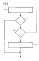
- decision block 18 The automatically recognized actual machine topology is shown in decision block 18 after verification or confirmation by the user for the further procedure. if the Verification reveals that the automatically recognized actual machine topology is faulty, then either the invention Method, as drawn in FIG. 2, according to a Checking the machine can be repeated or it can individual parameters can be corrected by hand. decision block 18 is only in the context of an advantageous Embodiment, optional to see. If necessary, the Decision block 18 is also omitted and equal to the decision block 17 can be jumped to the function block 19 or it may be decision block 18 before the function block 17 are executed.
- one Parameterization surface tailored to the actual machine topology are generated by the method according to the invention and the recognized actual machine topology as the second target machine topology 13b together with the associated second Parameterization surface file 14b stored in the storage medium 12 become.
- the ID number for identification describes the machine component as comprehensively as possible.
- the ID number can be serial number, Order number, software version, performance data and / or type of execution or manufacturer designation and / or the manufacturer include.
Abstract
Description
Die Erfindung bezieht sich auf ein Verfahren zur automatischen Konfiguration einer Parametrieroberfläche für mindestens eine Regelung und/oder mindestens eine Steuerung von Werkzeugmaschinen oder Produktionsmaschinen, sowie auf ein Datennetzwerk, zur Verbindung von Maschinenkomponenten bei Werkzeug- oder Produktionsmaschinen.The invention relates to a method for automatic Configuration of a parameterization interface for at least a regulation and / or at least a control of Machine tools or production machines, as well as on a Data network, for connecting machine components at Machine tools or production machines.
Werkzeug- und/oder Produktionsmaschinen, wobei unter Produktionsmaschinen auch Roboter zu verstehen sind, werden vom Hersteller häufig in unterschiedlichen Varianten angeboten, die aus einer Grundkonfiguration und optionalen Zusatzkomponenten oder Funktion bestehen. Diese Optionen werden teilweise auch erst nach Auslieferung an den Endkunden nachgerüstet. Nach der mechanischen und elektrischen Installation solcher optionaler Komponenten sind in der Regel Projektierungs- und Inbetriebsetzungsarbeiten an der Regelung und/oder Steuerung der Maschine vorzunehmen.Machine tools and / or production machines, being under production machines robots are also understood by the Manufacturers often offered in different variants, that from a basic configuration and optional additional components or function exist. These options are partial also retrofitted only after delivery to the end customer. After the mechanical and electrical installation of such optional components are usually configuration and Commissioning work on the regulation and / or control the machine.
Eine weitere Problemstellung sind Produktionsmaschinen, auf denen unterschiedliche Produkte hergestellt werden sollen oder mit verschiedenen Rezepturen gearbeitet werden soll. Dort werden häufig verschiedene Maschinenteile in unterschiedlichen Konfigurationen verkettet oder zu einer Grundmaschine optionale Maschinenteile hinzugefügt.Another problem are production machines on which different products are to be manufactured or to work with different recipes. There are often different machine parts in different Configurations linked or to a basic machine optional machine parts added.
Bisher waren einzelne Maschinenkomponenten immer fest miteinander verkoppelt. Die einzelnen Maschinenkomponenten, wie z.B. Geber oder Motoren, Ein-/Ausgabebaugruppen sowie Leistungssteller waren nicht über Datenleitungen miteinander verbunden, die den Austausch von Parametern, welche die jeweilige Maschinenkomponente beschreiben, erlaubt hätten. Infolge war es bisher einer Regelung oder einer Steuerung der Maschine nicht möglich, die angeschlossene Maschinenkonfiguration bzw. die angeschlossenen Maschinenkomponenten selbständig zu erkennen. Deshalb wurden in den Maschinen bislang nur statische Parametrieroberflächen zur Parametrierung der Maschinenkomponenten insbesondere der Regelung und Steuerung verwendet. Infolge musste praktisch für jede vom Anwender gewünschte Maschinenoption bzw. Maschinenkonfiguration vom Hersteller eine passende Parametrieroberfläche zur Parametrierung der Maschinenkomponenten vorab manuell konfiguriert werden.Up until now, individual machine components have always been fixed to one another coupled. The individual machine components, such as e.g. Encoders or motors, input / output modules and power controllers were not connected to each other via data lines, which are the exchange of parameters which are the respective Describe machine component, would have allowed. As a result it was previously a regulation or control of the machine not possible, the connected machine configuration or the connected machine components independently detect. That is why so far only static ones have been used in the machines Parameterization interfaces for parameterizing the machine components used in particular the regulation and control. As a result, practically everyone had to do what the user wanted Machine option or machine configuration from the manufacturer a suitable parameterization interface for parameterizing the Machine components can be configured manually in advance.
Der Erfindung liegt daher die Aufgabe zugrunde, ein Verfahren zur automatischen Konfiguration einer Parametrieroberfläche für Regelung und/oder Steuerung von Werkzeugmaschinen oder Produktionsmaschinen anzugeben, bei der eine individuell auf die momentane Maschinentopologie zugeschnittene Parametrieroberfläche generiert wird, sowie ein hierfür geeignetes Datennetzwerk zur Verbindung von Maschinenkomponenten der Maschinen zu schaffen.The invention is therefore based on the object of a method for automatic configuration of a parameterization interface for regulation and / or control of machine tools or To specify production machines, where one individually the parameterization surface tailored to the current machine topology is generated, as well as a suitable data network for connecting machine components of the machines to accomplish.
Die Aufgabe wird für das erfindungsgemäße Verfahren dadurch gelöst, dass bei Inbetriebnahme der Maschine über ein Datennetzwerk, welches Maschinenkomponenten untereinander verbindet, eine automatische Identifizierung der momentan angeschlossenen Komponenten sowie eine automatische Identifizierung der Struktur des Datennetzwerks durchgeführt wird und solchermaßen eine aktuelle Ist-Maschinentopologie erkannt wird, dass diese mit hinterlegten Soll-Maschinentopologien verglichen wird und falls keine Übereinstimmung mit einer der hinterlegten Sollmaschinentopologien festgestellt wird, anhand der ermittelten Ist-Maschinentopologie eine auf diese zugeschnittene Parametrieroberfläche generiert wird, bei der lediglich die Parameter und/oder Funktionen der erkannten Maschinenkomponenten zur Parametrierung der Regelung und/oder Steuerung der Maschine dem Bediener angezeigt werden. The task for the inventive method is thereby solved that when the machine is started up via a data network, which machine components connect to each other, automatic identification of the currently connected Components as well as automatic identification the structure of the data network is carried out and a current actual machine topology was recognized in this way is that this with stored target machine topologies is compared and if there is no match with any of the stored target machine topologies is determined based on the determined actual machine topology one on this tailored parameterization interface is generated in which only the parameters and / or functions of the recognized machine components for parameterizing the control and / or Control of the machine can be displayed to the operator.
Für ein Datennetzwerk zur Verbindung von Maschinenkomponenten bei Werkzeug- oder Produktionsmaschinen wird die oben genannte Aufgabe erfindungsgemäß dadurch gelöst, dass die Maschinenkomponenten über einheitliche Datenschnittstellen zum Austausch von Daten verbindbar sind, wobei die Datenschnittstellen als physikalische Punkt zu Punkt-Verbindungen ausführbar sind, wobei die Maschinenkomponenten jeweils eine eigene Intelligenz, insbesondere einen Controller und eine eigene ID-Nummer, besitzen.For a data network to connect machine components for machine tools or production machines, the above is used Object achieved according to the invention in that the machine components via uniform data interfaces for exchange of data are connectable, the data interfaces Can be implemented as a physical point-to-point connection are, whereby the machine components each have their own intelligence, especially a controller and its own ID number, have.
Eine erste vorteilhafte Ausbildung des erfindungsgemäßen Verfahrens ist dadurch gekennzeichnet, dass nach erfolgter automatischer Erkennung der Ist-Maschinentopologie und Vergleich mit hinterlegten Soll-Maschinentopologien eine Bestätigung der erkannten Ist-Maschinentopologie durch den Bediener erfolgt, bevor das erfindungsgemäße Verfahren fortgesetzt wird. Eine eventuell falsch erkannte Ist-Maschinentopologie kann hierdurch schon sehr frühzeitig vom Anwender erkannt werden.A first advantageous embodiment of the method according to the invention is characterized in that after the automatic Detection of the actual machine topology and comparison a confirmation with stored machine topologies the recognized actual machine topology is carried out by the operator, before the method according to the invention is continued. A possibly incorrectly recognized actual machine topology can hereby be recognized very early by the user.
Eine weitere vorteilhafte Ausbildung des erfindungsgemäßen Verfahrens ist dadurch gekennzeichnet, dass die automatische Identifizierung der momentan angeschlossenen Maschinenkomponenten mittels einer ID-Nummer, welche jede angeschlossene Maschinenkomponente kennzeichnet, durchgeführt wird. Hierdurch ist eine sehr sichere und eindeutige Identifizierung der angeschlossenen Maschinenkomponente gewährleistet.Another advantageous embodiment of the invention The procedure is characterized in that the automatic Identification of the currently connected machine components by means of an ID number, which each connected Identifies machine component is carried out. hereby is a very secure and clear identification of the connected machine components.
In diesem Zusammenhang erweist es sich als vorteilhaft, dass die ID-Nummer die Daten der jeweiligen Maschinenkomponente, insbesondere die Seriennummer und/oder Bestellnummer und/oder Softwarestand und/oder Ausführungstyp und/oder Herstellerbezeichnung und/oder Hersteller und/oder Leistungsdaten, beinhaltet. Eine möglichst umfassende Beschreibung der Maschinenkomponente, mittels einer entsprechenden ID-Nummer, erlaubt eine eindeutige und zuverlässige Identifizierung der Maschinenkomponente. In this context, it proves advantageous that the ID number the data of the respective machine component, especially the serial number and / or order number and / or Software version and / or type of execution and / or manufacturer name and / or manufacturer and / or performance data. A description of the machine component that is as comprehensive as possible, by means of an appropriate ID number clear and reliable identification of the machine components.
Eine weitere vorteilhafte Ausführung der Erfindung ist dadurch gekennzeichnet, dass die einheitlichen Datenschnittstellen physikalisch als Ethernet-, Firewire- oder USB-Schnittstellen realisierbar sind. Mit Hilfe der genannten Datenschnittstellen ist ein besonders einfacher Aufbau des Datennetzwerks möglich.This is a further advantageous embodiment of the invention characterized that the uniform data interfaces physically as Ethernet, Firewire or USB interfaces are realizable. With the help of the mentioned data interfaces is a particularly simple structure of the data network possible.
Eine weitere vorteilhafte Ausführung der Erfindung ist dadurch gekennzeichnet, dass die ID-Nummer, die Seriennummer und/oder Bestellnummer und/oder Softwarestand und/oder Ausführungstyp und/oder Herstellerbezeichnung und/oder Hersteller und/oder Leistungsdaten beinhaltet. Eine möglichst umfassende Beschreibung der Maschinenkomponente, mittels einer entsprechenden ID-Nummer, erlaubt eine eindeutige und zuverlässige Identifizierung der Maschinenkomponente.This is a further advantageous embodiment of the invention marked that the ID number, the serial number and / or order number and / or software version and / or version type and / or manufacturer name and / or manufacturer and / or performance data. As comprehensive as possible Description of the machine component, using a corresponding ID number, allows a clear and reliable Identification of the machine component.
Eine weitere vorteilhafte Ausführung der Erfindung ist dadurch gekennzeichnet, dass als Maschinenkomponenten, mindestens ein Leistungssteller und/oder mindestens ein Motor und/oder mindestens ein Sensor und/oder mindestens ein Geber und/oder mindestens eine Ein-/Ausgabebaugruppe und/oder mindestens eine Regelung und/oder mindestens eine Steuerung vorgesehen sind. Leistungssteller, Motoren, Sensoren, Geber und Ein-/Ausgabebaugruppen stellen gängige Maschinenkomponenten dar.This is a further advantageous embodiment of the invention characterized that as machine components, at least a power controller and / or at least one motor and / or at least one sensor and / or at least one sensor and / or at least one input / output module and / or at least a regulation and / or at least one controller is provided are. Power controllers, motors, sensors, encoders and Input / output modules represent common machine components represents.
Ein Ausführungsbeispiel der Erfindung ist in der Zeichnung dargestellt und wird im folgenden näher erläutert. Dabei zeigen:
- FIG 1
- ein Blockschaltbild einer Maschine inklusive Datennetzwerk
- FIG 2
- ein Ablaufdiagramm des erfindungsgemäßen Verfahrens.
- FIG. 1
- a block diagram of a machine including data network
- FIG 2
- a flowchart of the inventive method.
In dem Blockschaltbild gemäß FIG 1 wird im wesentlichen eine
Maschine dargestellt, welche aus einer Grundmaschine 1 und
einem optionalen Maschinenteil 2 besteht. In dem Ausführungsbeispiel
wird z.B. zur Fertigung eines Produktes A die Maschine
nur in ihrer Form als Grundmaschine 1 benötigt, während
z.B. zur Fertigung eines zweiten Produktes B zusätzlich
ein optionaler Maschinenanteil 2 zur Grundmaschine 1 dazugeschalten
werden muss. In dem Ausführungsbeispiel besteht die
Grundmaschine 1 aus den Maschinenkomponenten Regelung 5,
Leistungssteller 6a, Motor 7a und einem Geber 8a. Der optionale
Maschinenanteil 2 setzt sich beispielhaft aus einem
Leistungssteller 6b, einen Motor 7b, einem Geber 8b, sowie
einer Ein-/Ausgabebaugruppe 9 zusammen. Die einzelnen Maschinenkomponenten
sind über ein Datennetzwerk, welches im wesentlichen
aus dem physikalischen Punkt-zu-Punkt-Verbindungen
10a, 10b, 10c, 10d, 10e, 10f und 10g besteht, miteinander
verbunden. Im dem Ausführungsbeispiel sind die Schnittstellen
der einzelnen Maschinenkomponenten physikalisch als Ethernet-Schnittstellen
realisiert. Es sind aber auch alternativ als
physikalische Schnittstellen Firewire- oder USB-Schnittstellen
(Universal Serial Bus Schnittstellen) denkbar.In the block diagram of FIG 1 is essentially a
Machine shown, which consists of a basic machine 1 and
there is an
Jede in den Ausführungsbeispielen dargestellte Maschinenkomponente
verfügt über eine eigene Intelligenz 15a, 15b, 15c,
15d, 15e, 15f, 15g und 15h, beispielsweise in Form eines
Controllers. Weiterhin besitzt jede Maschinenkomponente zur
eindeutigen Identifikation eine eigene ID-Nummer 11a, 11b,
11c, 11d, 11e, 11f, 11g sowie 11h. Eine übergeordnete Automatisierungsebene
3, welche nicht zur Maschine gehört ist über
einen Feldbus 4 mit der Grundmaschine 1 bzw. der Regelung 5
verbunden.Each machine component shown in the exemplary embodiments
has its
Die Regelung 5 besitzt ein Speichermedium 12, welches vorzugsweise
als nichtflüchtiges Speichermedium 12 realisiert
ist. Im Speichermedium 12 ist im Ausführungsbeispiel eine
erste Soll-Maschinentopologie 13a, eine zweite Soll-Maschinentopologie
13b, eine erste Parametrieroberflächendatei
14a und eine zweite Parametrieroberflächendatei 14b hinterlegt. The control 5 has a
Jede Soll-Maschinentopologie ist eine Parametrieroberflächendatei zugeordnet, was jeweils durch eine gestrichelt gezeichnete Verbindung in FIG 1 angedeutet ist. Jede Parametrieroberflächendatei enthält die auf die jeweilige Soll-Maschinentopologie zugehörigen Parameter zur Konfiguration der Parametrieroberfläche. Als Beispiel für einen einzelnen Parameter innerhalb einer solchen Parametrieroberflächendatei wäre z.B. ein Verstärkungsfaktor eines Antriebsregelkreises zu nennen.Each target machine topology is a parameterization user interface file assigned, each represented by a dashed line Connection is indicated in FIG 1. Any configuration interface file contains the respective target machine topology associated parameters for configuring the parameterization interface. As an example of a single parameter would be within such a configuration interface file e.g. a gain of a drive control loop too call.
In dem Ausführungsbeispiel ist der Grundmaschine 1 eine erste
Soll-Maschinentopologie 13a und eine erste Parametrieroberflächendatei
14a zugeordnet. Besteht die Maschine aus der
Grundmaschine 1 und dem optionalen Maschinenanteil 2, d.h.,
ist der optionale Maschinenanteil 2 angeschlossen, so ist der
Maschine die zweite Soll-Maschinentopologie 13b und eine
zweite Parametrieroberflächendatei 14b zugeordnet. Die einzelnen
Soll-Maschinentopologien bzw. zugehörigen Parametrieroberflächendateien
werden vom Hersteller oder vom entsprechenden
Fachpersonal bei der Inbetriebnahme der Maschine mit
dem erfindungsgemäßen Verfahren erstellt und im Speichermedium
12 hinterlegt.In the exemplary embodiment, the basic machine 1 is a first one
Selbstverständlich kann anstatt oder zusätzlich zur Regelung 5 auch eine Steuerung mit einem entsprechenden Speichermedium und den entsprechenden Soll-Maschinentopologien bzw. Parametrieroberflächendateien oder mehrere solcher Regelungen und/oder Steuerungen in der Maschine vorhanden sein. Weiterhin kann die Maschine auch aus wesentlich mehr optionalen Maschinenteilen bzw. Maschinenkomponenten bestehen. Auch können gegebenenfalls noch andere Arten von Maschinenkomponenten vorhanden sein.Of course, instead of or in addition to the regulation 5 also a controller with a corresponding storage medium and the corresponding target machine topologies or parameterization interface files or several such regulations and / or controls in the machine. Farther the machine can also consist of many more optional machine parts or machine components. Can too possibly other types of machine components to be available.
In FIG 2 ist ein Ausführungsbeispiel des erfindungsgemäßen Verfahrens als Ablaufdiagramm dargestellt. 2 shows an embodiment of the invention Procedure shown as a flow chart.
Zu Beginn der automatischen Konfiguration der im Ausführungsbeispiel
angegebenen Regelung 5 wird innerhalb des Funktionsblocks
16, beim Hochlaufen der Maschine über das Datennetzwerk
eine automatische Identifizierung der momentan angeschlossenen
Maschinenkomponenten, sowie eine automatische
Identifizierung der Struktur des Datennetzwerks, d.h. es wird
ermittelt wie im Datennetzwerk die Maschinenkomponenten untereinander
verbunden sind, durchgeführt und solchermaßen eine
aktuelle Ist-Maschinentopologie 20 erkannt. Die erkannte
Ist-Maschinentopologie 20 beinhaltet somit sowohl Informationen
über die Struktur des Datennetzwerks als auch eine Identifizierung
der angeschlossenen Maschinenkomponenten. Die
Identifizierung der Maschinenkomponenten kann dabei Daten wie
z.B. die Seriennummer und/oder Bestellnummer und/oder Softwarestand
und/oder Ausführungstyp und/oder Herstellerbezeichnung
und/oder Hersteller und/oder Leistungsdaten beinhalten.
In einer vorteilhaften Ausführungsform sind diese Daten in
Form einer ID-Nummer zusammengefasst, wobei unter Umständen,
falls nicht alle für das erfindungsgemäße Verfahren benötigten
Daten der Maschinenkomponenten in der ID-Nummer selbst
integiert sind, die betreffenden Maschinendaten über das Datennetzwerk
von der Regelung und/oder Steuerung, nachgeladen
werden müssen.At the beginning of the automatic configuration of the in the embodiment
specified regulation 5 is within the
Nach Ablauf der Topologieerkennung 16 wird innerhalb eines
Entscheidungsblocks 17 ein Vergleich der aktuell ermittelten
Ist-Maschinentopologie mit schon vorher abgespeicherten Soll-Maschinentopologien
durchgeführt. Die entsprechenden Soll-Maschinentopologien,
sowie die zugehörigen Parametrieroberflächendaten,
wurden entweder schon vom Hersteller hinterlegt
oder sind innerhalb frühere Inbetriebnahmen der Maschine
durch das erfindungsgemäße Verfahren bereits angelegt worden.
Ergibt der Vergleich, dass zu der aktuell erkannten Ist-Maschinentopologie
bereits eine identische Soll-Maschinentopologie
existiert, werden die Funktionsblöcke 18 und 19 übersprungen
und dem Anwender anhand der zur Soll-Maschinentopologie
zugehörigen Parametrieroberflächendatei eine zu der
entsprechenden Soll-Maschinentopologie zugehörige Parametrieroberfläche
zur Verfügung gestellt.After the
In dem Ausführungsbeispiel gemäß FIG 1 würde z.B. unter der
Vorraussetzung, dass die Maschine als Grundmaschine 1 ohne
optionalen Maschineanteil 2 konfiguriert ist und infolge einer
zu einem frühren Zeitpunkt durchgeführte Inbetriebnahme
der Maschine mit der selben Konfiguration, bereits eine zugehörige
erste Soll-Maschinentopologie 13a und zugehörige erste
Parametrieroberflächendatei 13b existiert, keine neue Parametrieroberfläche
mehr generiert werden, sondern dem Bediener,
eine Parametrieroberfläche anhand bzw. entsprechend der
schon existierenden ersten Parametrieroberflächendatei 13a zu
Verfügung gestellt werden.In the exemplary embodiment according to FIG. 1, e.g. under the
Prerequisite that the machine as basic machine 1 without
Falls innerhalb des Entscheidungsblock 17 festgestellt wird,
dass die erkannte Ist-Maschinentopologie mit keinen der abgespeicherten
Soll-Maschinentopologien übereinstimmt wird zum
Entscheidungsblock 18 verzweigt.If it is determined within
Im Entscheidungsblock 18 wird die automatisch erkannte Ist-Maschinentopologie
nach Überprüfung bzw. Bestätigung durch
den Anwender für das weitere Verfahren übernommen. Falls die
Überprüfung ergibt, dass die automatisch erkannte Ist-Maschinentopologie
fehlerhaft ist, dann kann entweder das erfindungsgemäße
Verfahren, wie in FIG 2 gezeichnet, nach einer
Überprüfung der Maschine wiederholt werden oder es können
einzelne Parameter per Hand korrigiert werden. Entscheidungsblock
18 ist hierbei lediglich, im Rahmen einer vorteilhaften
Ausführungsform, optional zu sehen. Gegebenenfalls kann der
Entscheidungsblock 18 auch entfallen und gleich von dem Entscheidungsblock
17 zum Funktionsblock 19 gesprungen werden
oder es kann der Entscheidungsblock 18 vor dem Funktionsblock
17 ausgeführt werden.The automatically recognized actual machine topology is shown in
Im Funktionsblock 19 erfolgt die Generierung der Parametrieroberfläche.
Anhand der ermittelten Ist-Maschinentopologie
wird eine auf diese zugeschnittene Parametrieroberfläche generiert,
bei der lediglich die Parameter und Funktionen der
erkannten Maschinenkomponenten zur Parametrierung der Regelung
und/oder Steuerung der Maschine dem Bediener angezeigt
werden. Wenn z.B. ein neuer Antrieb bestehend aus einem Leistungsstellermotor
und Drehzahlgeber erkannt wird, so werden
z.B. die zugehörigen Softwarepakete in der Regelung aktiviert
und deren Einstellparameter generiert und gegebenenfalls auch
herstellerseitig voreingestellt. Am Ende der automatischen
Konfiguration der Parametrieroberfläche stehen dann dem Anwender
alle Parameter und Funktionen zur Verfügung, die er
für die momentane Maschinenkonfiguration bzw. die momentane
Ist-Maschinentopologie benötigt. Nach erfolgter Parametrierung
bzw. Bestätigung der gegebenenfalls voreingestellten Parameter
wird die Ist-Maschinenkonfiguration als Soll-Maschinenkonfiguration
mit der dazugehörigen Parametrieroberflächendatei
im Speichermedium 12 abgelegt.The parameterization surface is generated in
In dem Ausführungsbeispiel gemäß FIG 1 würde z.B. unter der
Vorraussetzung, dass die Maschine, als Grundmaschine 1, die
zusammengeschaltet mit dem optionalen Maschineanteil 2 konfiguriert
ist und keine zu dieser Ist-Maschinenkonfiguration
zugehörige zweite Soll-Maschinentopologie 13b existiert, eine
auf die Ist-Maschinentopologie zugeschnittene Parametrieroberfläche
vom erfindungsgemäßen Verfahren generiert werden
und die erkannte Ist-Maschinentopologie als zweite Soll-Maschinentopologie
13b zusammen mit der zugehörigen zweiten
Parametrieroberflächendatei 14b im Speichermedium 12 gespeichert
werden.In the exemplary embodiment according to FIG. 1, e.g. under the
Prerequisite that the machine, as the basic machine 1, the
configured together with the
In manchen Anwendungsfällen kann es auch vorkommen, dass bestimmte Maschinenkomponenten, wie z.B. ein Motor über noch keine eigene Intelligenz (Controller) oder keinen Anschluss an das Datennetzwerk besitzen. In solchen Fällen lässt sich in der Regel trotzdem eine Ist-Maschinentopologie bestimmen, in dem z.B. herstellerseitig davon ausgegangen werden kann, dass jedem Leistungssteller genau ein bestimmter Motortyp nachgeschaltet ist, weil z.B. der betreffende Motortyp vom Hersteller immer für den erkannten Leistungssteller verwendet wird. Zur Durchführung des Verfahrens ist es also nicht zwangsweise notwendig, dass sämtliche Maschinenkomponenten mit einer eigenen Intelligenz bzw. eigenen ID-Nummer und einem Anschluss an das Datennetzwerk ausgestattet sind.In some applications it can also happen that certain Machine components, e.g. an engine over yet no own intelligence (controller) or no connection own the data network. In such cases, usually still determine an actual machine topology, in which e.g. can be assumed by the manufacturer that each power controller has exactly one specific motor type is connected downstream because e.g. the relevant engine type from Manufacturer always used for the recognized power controller becomes. So it is not to carry out the procedure imperative that all machine components with their own intelligence or ID number and one Connection to the data network are equipped.
Die aktuelle Ist-Maschinentopologie, sowie zusätzliche Daten,
wie z.B. der Zeitpunkt der Aktivierung der Ist-Maschinentopologie,
die Zeitdauer der Benutzung der Ist-Maschinentopologie
können gemäß FIG 1 über einen Feldbus 4 an eine übergeordnete
Automatisierungsebene 3 weitergeleitet werden. Sofern die Maschine
und/oder die übergeordnete Automatisierungsebene 3 mit
einem entsprechenden nicht in FIG 1 dargestellten Kommunikationsmittel
verbunden ist, z.B. Telefonnetz und/oder Internet/Intranet,
kann die aktuelle Ist-Maschinentopologie z.B.
vom Maschinenhersteller erfasst und überwacht werden.The current actual machine topology, as well as additional data,
such as. the time of activation of the actual machine topology,
the period of use of the actual machine topology
1 can via a fieldbus 4 to a higher-
Es sei an dieser Stelle angemerkt, dass für die oben genannten physikalischen Datenschnittstellen (Ethernet-, Firewire oder USB-Schnittstellen) unter Umständen nicht die Originalprotokolle dieser Schnittstellen verwendet werden können, da bei einigen Maschinen harte Anforderungen an die Echtzeitfähigkeit der zu übertragenden Daten gestellt werden. Deshalb müssen für einige Anwendungsfälle, die entsprechenden zu den physikalischen Schnittstellen gehörenden Protokolle in Richtung Echtzeitfähigkeit modifiziert werden.It should be noted at this point that for the above physical data interfaces (Ethernet, Firewire or USB interfaces) may not be the original protocols of these interfaces can be used because Some machines have tough real-time capability requirements of the data to be transferred. Therefore for some use cases, the corresponding to the protocols belonging to physical interfaces Real-time capability can be modified.
Weiterhin ist es sinnvoll, dass die ID-Nummer zur Identifikation der Maschinenkomponente diese möglichst umfassend beschreibt. So kann die ID-Nummer beispielsweise Seriennummer, Bestellnummer, Softwarestand, Leistungsdaten und/oder Ausführungstyp bzw. Herstellerbezeichnung und/oder den Hersteller beinhalten.It also makes sense that the ID number for identification describes the machine component as comprehensively as possible. For example, the ID number can be serial number, Order number, software version, performance data and / or type of execution or manufacturer designation and / or the manufacturer include.
Claims (9)
Applications Claiming Priority (2)
| Application Number | Priority Date | Filing Date | Title |
|---|---|---|---|
| DE10254010 | 2002-11-19 | ||
| DE10254010A DE10254010B4 (en) | 2002-11-19 | 2002-11-19 | Method for automatic configuration of a parameterization surface of machine tools or production machines |
Publications (3)
| Publication Number | Publication Date |
|---|---|
| EP1422629A2 true EP1422629A2 (en) | 2004-05-26 |
| EP1422629A3 EP1422629A3 (en) | 2007-04-11 |
| EP1422629B1 EP1422629B1 (en) | 2008-12-31 |
Family
ID=32185851
Family Applications (1)
| Application Number | Title | Priority Date | Filing Date |
|---|---|---|---|
| EP03023117A Expired - Fee Related EP1422629B1 (en) | 2002-11-19 | 2003-10-10 | Method for the automatic configuration of the display of parameters for machine tools or production machines |
Country Status (3)
| Country | Link |
|---|---|
| US (1) | US6981221B2 (en) |
| EP (1) | EP1422629B1 (en) |
| DE (2) | DE10254010B4 (en) |
Cited By (7)
| Publication number | Priority date | Publication date | Assignee | Title |
|---|---|---|---|---|
| WO2008089929A1 (en) * | 2007-01-23 | 2008-07-31 | Carl Zeiss Industrielle Messtechnik Gmbh | Control of an operation of a coordinate measuring device |
| EP2109020A1 (en) | 2008-04-10 | 2009-10-14 | Siemens Aktiengesellschaft | Automation system and method for diagnosis, customisation and optimisation of automation device |
| DE102009012832A1 (en) * | 2009-03-02 | 2010-09-09 | Khs Ag | Method and device for automatic integration of sensor devices in a central control |
| WO2012028366A1 (en) * | 2010-08-31 | 2012-03-08 | Endress+Hauser Process Solutions Ag | Method for ensuring proper functioning of an automation system |
| US8892785B2 (en) | 2007-08-21 | 2014-11-18 | Beckhoff Automation Gmbh | Programming device for a network of control nodes and system with such a programming device |
| WO2015181758A1 (en) * | 2014-05-29 | 2015-12-03 | Abb Technology Ltd. | A method and system for configuration of devices of a control system |
| EP3599525A1 (en) | 2018-07-27 | 2020-01-29 | Dr. Johannes Heidenhain GmbH | Method for secure data communication on a numerically controlled machine tool |
Families Citing this family (39)
| Publication number | Priority date | Publication date | Assignee | Title |
|---|---|---|---|---|
| US8145759B2 (en) | 2002-11-04 | 2012-03-27 | Oracle America, Inc. | Dynamically configurable resource pool |
| US7743083B2 (en) | 2003-04-24 | 2010-06-22 | Oracle America, Inc. | Common transaction manager interface for local and global transactions |
| US7610305B2 (en) | 2003-04-24 | 2009-10-27 | Sun Microsystems, Inc. | Simultaneous global transaction and local transaction management in an application server |
| US7640545B2 (en) * | 2003-07-14 | 2009-12-29 | Sun Microsytems, Inc. | Transaction manager freezing |
| US7739252B2 (en) * | 2003-07-14 | 2010-06-15 | Oracle America, Inc. | Read/write lock transaction manager freezing |
| US7134008B2 (en) * | 2003-09-04 | 2006-11-07 | Sun Microsystems, Inc. | Utility for configuring and verifying data sources |
| US8521875B2 (en) * | 2003-09-04 | 2013-08-27 | Oracle America, Inc. | Identity for data sources |
| DE102004024883B4 (en) * | 2004-05-19 | 2006-02-02 | Siemens Ag | drive system |
| US7904488B2 (en) | 2004-07-21 | 2011-03-08 | Rockwell Automation Technologies, Inc. | Time stamp methods for unified plant model |
| US8756521B1 (en) | 2004-09-30 | 2014-06-17 | Rockwell Automation Technologies, Inc. | Systems and methods for automatic visualization configuration |
| US7676281B2 (en) | 2005-05-13 | 2010-03-09 | Rockwell Automation Technologies, Inc. | Distributed database in an industrial automation environment |
| US8799800B2 (en) | 2005-05-13 | 2014-08-05 | Rockwell Automation Technologies, Inc. | Automatic user interface generation |
| US7672737B2 (en) | 2005-05-13 | 2010-03-02 | Rockwell Automation Technologies, Inc. | Hierarchically structured data model for utilization in industrial automation environments |
| US7809683B2 (en) * | 2005-05-13 | 2010-10-05 | Rockwell Automation Technologies, Inc. | Library that includes modifiable industrial automation objects |
| US7650405B2 (en) * | 2005-05-13 | 2010-01-19 | Rockwell Automation Technologies, Inc. | Tracking and tracing across process boundaries in an industrial automation environment |
| DE102005025645A1 (en) * | 2005-06-03 | 2006-12-07 | Bomag Gmbh | Construction machine e.g. packing equipment, control device configuration method, involves embedding data memory into machine control, and storing configuration data in data memory of control device to be configured |
| DE102005040434A1 (en) * | 2005-08-25 | 2007-03-01 | Phoenix Contact Gmbh & Co. Kg | Method and system for mapping the structure of an automation system on a computer |
| US20070067458A1 (en) * | 2005-09-20 | 2007-03-22 | Rockwell Software, Inc. | Proxy server for integration of industrial automation data over multiple networks |
| US7881812B2 (en) * | 2005-09-29 | 2011-02-01 | Rockwell Automation Technologies, Inc. | Editing and configuring device |
| US7548789B2 (en) | 2005-09-29 | 2009-06-16 | Rockwell Automation Technologies, Inc. | Editing lifecycle and deployment of objects in an industrial automation environment |
| US7526794B2 (en) * | 2005-09-30 | 2009-04-28 | Rockwell Automation Technologies, Inc. | Data perspectives in controller system and production management systems |
| US7734590B2 (en) | 2005-09-30 | 2010-06-08 | Rockwell Automation Technologies, Inc. | Incremental association of metadata to production data |
| US7801628B2 (en) | 2005-09-30 | 2010-09-21 | Rockwell Automation Technologies, Inc. | Industrial operator interfaces interacting with higher-level business workflow |
| US7660638B2 (en) * | 2005-09-30 | 2010-02-09 | Rockwell Automation Technologies, Inc. | Business process execution engine |
| US8275680B2 (en) * | 2005-09-30 | 2012-09-25 | Rockwell Automation Technologies, Inc. | Enabling transactional mechanisms in an automated controller system |
| US8484250B2 (en) * | 2005-09-30 | 2013-07-09 | Rockwell Automation Technologies, Inc. | Data federation with industrial control systems |
| DE102006041251C5 (en) * | 2006-09-02 | 2016-04-14 | Leuze Lumiflex Gmbh + Co. Kg | Device for detecting objects in a surveillance area |
| EP1935577A1 (en) * | 2006-12-21 | 2008-06-25 | Abb Ab | A control system for controlling an industrial robot |
| DE102008010011A1 (en) * | 2008-02-20 | 2009-10-29 | Dr. Johannes Heidenhain Gmbh | Procedure for commissioning a numerical control |
| FR2931969B1 (en) * | 2008-06-03 | 2010-08-20 | Univ Poitiers | ELECTRONIC CARD AND SYSTEM COMPRISING A PLURALITY OF SUCH CARDS |
| JP4598865B2 (en) * | 2009-02-17 | 2010-12-15 | ファナック株式会社 | Robot control device used in combination with machine tools |
| US9392072B2 (en) | 2010-04-15 | 2016-07-12 | Rockwell Automation Technologies, Inc. | Systems and methods for conducting communications among components of multidomain industrial automation system |
| US8484401B2 (en) | 2010-04-15 | 2013-07-09 | Rockwell Automation Technologies, Inc. | Systems and methods for conducting communications among components of multidomain industrial automation system |
| US8984533B2 (en) | 2010-04-15 | 2015-03-17 | Rockwell Automation Technologies, Inc. | Systems and methods for conducting communications among components of multidomain industrial automation system |
| JP5120473B2 (en) | 2011-03-15 | 2013-01-16 | オムロン株式会社 | Network system design support device |
| DE102015002922A1 (en) * | 2015-03-04 | 2016-09-08 | Oerlikon Textile Gmbh & Co. Kg | Machinery for the production or treatment of synthetic threads |
| EP3076541A1 (en) | 2015-03-31 | 2016-10-05 | Siemens Aktiengesellschaft | Drive device with inertia factor estimation |
| DE102017010473A1 (en) * | 2017-11-10 | 2019-05-16 | Oerlikon Textile Gmbh & Co. Kg | Machinery for the production or treatment of synthetic threads |
| WO2019143383A1 (en) * | 2018-01-22 | 2019-07-25 | Siemens Aktiengesellschaft | Skill matching for control of an industrial production machine |
Citations (5)
| Publication number | Priority date | Publication date | Assignee | Title |
|---|---|---|---|---|
| EP0747795A2 (en) * | 1995-06-07 | 1996-12-11 | Xerox Corporation | A system for generically describing and scheduling operation of a modular printing machine |
| US5901323A (en) * | 1990-12-11 | 1999-05-04 | Fisher Controls International, Inc. | Process controller with interchangeable individual I/O units |
| WO2001090829A2 (en) * | 2000-05-24 | 2001-11-29 | Schneider Automation Inc. | System for remote configuration monitoring of an industrial control system |
| DE10027006A1 (en) * | 2000-05-31 | 2001-12-06 | Bosch Gmbh Robert | System for controlling and regulating running processes in a motor vehicle and method for starting it up uses indirect memory access points for control devices to load required programs into their operating memory. |
| EP1225491A1 (en) * | 2001-01-23 | 2002-07-24 | G.D Societ Per Azioni | Method and unit for changing the configuration of an automatic machine |
Family Cites Families (12)
| Publication number | Priority date | Publication date | Assignee | Title |
|---|---|---|---|---|
| US5737319A (en) * | 1996-04-15 | 1998-04-07 | Mci Corporation | Dynamic network topology determination |
| US5958012A (en) * | 1996-07-18 | 1999-09-28 | Computer Associates International, Inc. | Network management system using virtual reality techniques to display and simulate navigation to network components |
| US5850343A (en) * | 1996-08-26 | 1998-12-15 | Nakamura; Kaoru | Machine tool control system |
| US6040834A (en) * | 1996-12-31 | 2000-03-21 | Cisco Technology, Inc. | Customizable user interface for network navigation and management |
| US6349352B1 (en) * | 1998-01-06 | 2002-02-19 | Sony Corporation Of Japan | Home audio/video network with both generic and parameterized device control |
| US6205122B1 (en) * | 1998-07-21 | 2001-03-20 | Mercury Interactive Corporation | Automatic network topology analysis |
| FR2802745B1 (en) * | 1999-12-21 | 2002-03-22 | Cie Generale D Inf Et De Telec | ASSISTANCE STATION FOR SETTING UP A TELECOMMUNICATIONS NETWORK |
| US20010034567A1 (en) * | 2000-01-20 | 2001-10-25 | Allen Marc L. | Remote management of retail petroleum equipment |
| US6735548B1 (en) * | 2001-04-10 | 2004-05-11 | Cisco Technology, Inc. | Method for automated network availability analysis |
| US7086950B2 (en) * | 2001-10-03 | 2006-08-08 | Stephen Eugene Gordon | Cuckoo clock gaming device |
| US20030069960A1 (en) * | 2001-10-04 | 2003-04-10 | Symons Julie A. | Method for describing and comparing data center physical and logical topologies and device configurations |
| US7219300B2 (en) * | 2002-09-30 | 2007-05-15 | Sanavigator, Inc. | Method and system for generating a network monitoring display with animated utilization information |
-
2002
- 2002-11-19 DE DE10254010A patent/DE10254010B4/en not_active Expired - Fee Related
-
2003
- 2003-10-10 DE DE50310995T patent/DE50310995D1/en not_active Expired - Lifetime
- 2003-10-10 EP EP03023117A patent/EP1422629B1/en not_active Expired - Fee Related
- 2003-11-14 US US10/713,968 patent/US6981221B2/en not_active Expired - Lifetime
Patent Citations (5)
| Publication number | Priority date | Publication date | Assignee | Title |
|---|---|---|---|---|
| US5901323A (en) * | 1990-12-11 | 1999-05-04 | Fisher Controls International, Inc. | Process controller with interchangeable individual I/O units |
| EP0747795A2 (en) * | 1995-06-07 | 1996-12-11 | Xerox Corporation | A system for generically describing and scheduling operation of a modular printing machine |
| WO2001090829A2 (en) * | 2000-05-24 | 2001-11-29 | Schneider Automation Inc. | System for remote configuration monitoring of an industrial control system |
| DE10027006A1 (en) * | 2000-05-31 | 2001-12-06 | Bosch Gmbh Robert | System for controlling and regulating running processes in a motor vehicle and method for starting it up uses indirect memory access points for control devices to load required programs into their operating memory. |
| EP1225491A1 (en) * | 2001-01-23 | 2002-07-24 | G.D Societ Per Azioni | Method and unit for changing the configuration of an automatic machine |
Cited By (14)
| Publication number | Priority date | Publication date | Assignee | Title |
|---|---|---|---|---|
| US8600523B2 (en) | 2007-01-23 | 2013-12-03 | Carl Zeiss Industrielle Messtechnik Gmbh | Control of an operation of a coordinate measuring device |
| WO2008089929A1 (en) * | 2007-01-23 | 2008-07-31 | Carl Zeiss Industrielle Messtechnik Gmbh | Control of an operation of a coordinate measuring device |
| US8892785B2 (en) | 2007-08-21 | 2014-11-18 | Beckhoff Automation Gmbh | Programming device for a network of control nodes and system with such a programming device |
| EP2109020A1 (en) | 2008-04-10 | 2009-10-14 | Siemens Aktiengesellschaft | Automation system and method for diagnosis, customisation and optimisation of automation device |
| WO2010099811A1 (en) | 2009-03-02 | 2010-09-10 | Khs Ag | Method and device for automatically integrating sensor devices in a central controller |
| CN102282515A (en) * | 2009-03-02 | 2011-12-14 | Khs有限责任公司 | Method and device for automatically integrating sensor devices in a central controller |
| CN102282515B (en) * | 2009-03-02 | 2014-03-26 | Khs有限责任公司 | Method and device for automatically integrating sensor devices in a central controller |
| DE102009012832A1 (en) * | 2009-03-02 | 2010-09-09 | Khs Ag | Method and device for automatic integration of sensor devices in a central control |
| WO2012028366A1 (en) * | 2010-08-31 | 2012-03-08 | Endress+Hauser Process Solutions Ag | Method for ensuring proper functioning of an automation system |
| WO2015181758A1 (en) * | 2014-05-29 | 2015-12-03 | Abb Technology Ltd. | A method and system for configuration of devices of a control system |
| CN106662854A (en) * | 2014-05-29 | 2017-05-10 | Abb瑞士股份有限公司 | A method and system for configuration of devices of a control system |
| CN106662854B (en) * | 2014-05-29 | 2019-01-15 | Abb瑞士股份有限公司 | The method and system of the configuration of device for control system |
| US10523502B2 (en) | 2014-05-29 | 2019-12-31 | Abb Schweiz Ag | Method and system for configuration of devices of a control system |
| EP3599525A1 (en) | 2018-07-27 | 2020-01-29 | Dr. Johannes Heidenhain GmbH | Method for secure data communication on a numerically controlled machine tool |
Also Published As
| Publication number | Publication date |
|---|---|
| DE10254010A1 (en) | 2004-06-17 |
| US6981221B2 (en) | 2005-12-27 |
| US20040098153A1 (en) | 2004-05-20 |
| EP1422629B1 (en) | 2008-12-31 |
| DE10254010B4 (en) | 2009-01-02 |
| EP1422629A3 (en) | 2007-04-11 |
| DE50310995D1 (en) | 2009-02-12 |
Similar Documents
| Publication | Publication Date | Title |
|---|---|---|
| EP1422629B1 (en) | Method for the automatic configuration of the display of parameters for machine tools or production machines | |
| EP1119434B1 (en) | Regulating device for a welding apparatus | |
| EP2315088B1 (en) | Safety control | |
| EP2591404B1 (en) | Method for configuring a control device | |
| DE102007026678A1 (en) | Method for exchanging a defective field device for a new field device in a system communicating via a digital field bus, in particular an automation system | |
| EP1779203A1 (en) | Identification of parameters for field devices used in automation technology | |
| EP1430369B1 (en) | Dynamic access to automation resources | |
| DE10243856B4 (en) | Regulator and method for operating a regulator | |
| DE10208530A1 (en) | Method for configuration and operation of peripheral devices connected to a host unit via a field bus in which the peripherals are supplied with a configuration file so that they can be directly configured by the host over the bus | |
| EP3298730A1 (en) | Bus system and method for assigning addresses of bus components of a bus system | |
| DE102016115988A1 (en) | MACHINE CONTROL SYSTEM WHICH SHOWS MACHINE OPERATING INFORMATION ON A DISPLAY DEVICE CORRESPONDING TO AN OPERATOR | |
| DE102009051720A1 (en) | Commissioning procedure | |
| EP1903530B1 (en) | Assembly with vacuum device and method for its operation | |
| DE102010033039A1 (en) | Method for providing security functions | |
| DE10254009A1 (en) | Data network and method for use in automatic configuration and commissioning of machine tools or production machinery, determines actual machine topology and configures with tailored data after network created | |
| EP1998240B1 (en) | Control system with cyclical operation and method for incorporating software building blocks in the functional process of a control system | |
| DE102016123599A1 (en) | Robot controller with function for communication with a programmable logic controller and communication system | |
| EP2511777A1 (en) | Method for operating a drive control device and device control device with means for use in such a method | |
| EP1524566B1 (en) | Control method for production machine | |
| EP3076254A1 (en) | Method for operating a control system for a technical process and control system | |
| EP1331534A2 (en) | Automation system and method for generating a documentation | |
| EP1179428B1 (en) | Method and device for working through process steps | |
| EP1455251B1 (en) | Configurable safety switching device | |
| EP2315090A1 (en) | Real-time control method for a control apparatus for a industrial technical process and real-time operating method for a computing apparatus | |
| WO2008145623A1 (en) | Control device and drive component for a machine tool, a production machine and/or a robot |
Legal Events
| Date | Code | Title | Description |
|---|---|---|---|
| PUAI | Public reference made under article 153(3) epc to a published international application that has entered the european phase |
Free format text: ORIGINAL CODE: 0009012 |
|
| AK | Designated contracting states |
Kind code of ref document: A2 Designated state(s): AT BE BG CH CY CZ DE DK EE ES FI FR GB GR HU IE IT LI LU MC NL PT RO SE SI SK TR |
|
| AX | Request for extension of the european patent |
Extension state: AL LT LV MK |
|
| PUAL | Search report despatched |
Free format text: ORIGINAL CODE: 0009013 |
|
| AK | Designated contracting states |
Kind code of ref document: A3 Designated state(s): AT BE BG CH CY CZ DE DK EE ES FI FR GB GR HU IE IT LI LU MC NL PT RO SE SI SK TR |
|
| AX | Request for extension of the european patent |
Extension state: AL LT LV MK |
|
| 17P | Request for examination filed |
Effective date: 20070507 |
|
| 17Q | First examination report despatched |
Effective date: 20070814 |
|
| AKX | Designation fees paid |
Designated state(s): DE FR GB |
|
| GRAP | Despatch of communication of intention to grant a patent |
Free format text: ORIGINAL CODE: EPIDOSNIGR1 |
|
| RTI1 | Title (correction) |
Free format text: METHOD FOR THE AUTOMATIC CONFIGURATION OF THE DISPLAY OF PARAMETERS FOR MACHINE TOOLS OR PRODUCTION MACHINES |
|
| GRAS | Grant fee paid |
Free format text: ORIGINAL CODE: EPIDOSNIGR3 |
|
| GRAA | (expected) grant |
Free format text: ORIGINAL CODE: 0009210 |
|
| AK | Designated contracting states |
Kind code of ref document: B1 Designated state(s): DE FR GB |
|
| REG | Reference to a national code |
Ref country code: GB Ref legal event code: FG4D Free format text: NOT ENGLISH |
|
| REF | Corresponds to: |
Ref document number: 50310995 Country of ref document: DE Date of ref document: 20090212 Kind code of ref document: P |
|
| PLBE | No opposition filed within time limit |
Free format text: ORIGINAL CODE: 0009261 |
|
| STAA | Information on the status of an ep patent application or granted ep patent |
Free format text: STATUS: NO OPPOSITION FILED WITHIN TIME LIMIT |
|
| 26N | No opposition filed |
Effective date: 20091001 |
|
| PGFP | Annual fee paid to national office [announced via postgrant information from national office to epo] |
Ref country code: FR Payment date: 20091029 Year of fee payment: 7 Ref country code: GB Payment date: 20091019 Year of fee payment: 7 |
|
| GBPC | Gb: european patent ceased through non-payment of renewal fee |
Effective date: 20101010 |
|
| PG25 | Lapsed in a contracting state [announced via postgrant information from national office to epo] |
Ref country code: FR Free format text: LAPSE BECAUSE OF NON-PAYMENT OF DUE FEES Effective date: 20101102 |
|
| REG | Reference to a national code |
Ref country code: FR Ref legal event code: ST Effective date: 20110630 |
|
| PG25 | Lapsed in a contracting state [announced via postgrant information from national office to epo] |
Ref country code: GB Free format text: LAPSE BECAUSE OF NON-PAYMENT OF DUE FEES Effective date: 20101010 |
|
| PGFP | Annual fee paid to national office [announced via postgrant information from national office to epo] |
Ref country code: DE Payment date: 20201218 Year of fee payment: 18 |
|
| REG | Reference to a national code |
Ref country code: DE Ref legal event code: R119 Ref document number: 50310995 Country of ref document: DE |
|
| PG25 | Lapsed in a contracting state [announced via postgrant information from national office to epo] |
Ref country code: DE Free format text: LAPSE BECAUSE OF NON-PAYMENT OF DUE FEES Effective date: 20220503 |