EP1422068A1 - Apparatus for printing and memory tag application and method therefor - Google Patents
Apparatus for printing and memory tag application and method therefor Download PDFInfo
- Publication number
- EP1422068A1 EP1422068A1 EP03257030A EP03257030A EP1422068A1 EP 1422068 A1 EP1422068 A1 EP 1422068A1 EP 03257030 A EP03257030 A EP 03257030A EP 03257030 A EP03257030 A EP 03257030A EP 1422068 A1 EP1422068 A1 EP 1422068A1
- Authority
- EP
- European Patent Office
- Prior art keywords
- base medium
- memory tag
- memory
- print head
- dispenser
- Prior art date
- Legal status (The legal status is an assumption and is not a legal conclusion. Google has not performed a legal analysis and makes no representation as to the accuracy of the status listed.)
- Withdrawn
Links
Images


Classifications
-
- B—PERFORMING OPERATIONS; TRANSPORTING
- B41—PRINTING; LINING MACHINES; TYPEWRITERS; STAMPS
- B41J—TYPEWRITERS; SELECTIVE PRINTING MECHANISMS, i.e. MECHANISMS PRINTING OTHERWISE THAN FROM A FORME; CORRECTION OF TYPOGRAPHICAL ERRORS
- B41J3/00—Typewriters or selective printing or marking mechanisms characterised by the purpose for which they are constructed
- B41J3/44—Typewriters or selective printing mechanisms having dual functions or combined with, or coupled to, apparatus performing other functions
- B41J3/50—Mechanisms producing characters by printing and also producing a record by other means, e.g. printer combined with RFID writer
-
- B—PERFORMING OPERATIONS; TRANSPORTING
- B65—CONVEYING; PACKING; STORING; HANDLING THIN OR FILAMENTARY MATERIAL
- B65C—LABELLING OR TAGGING MACHINES, APPARATUS, OR PROCESSES
- B65C9/00—Details of labelling machines or apparatus
- B65C9/46—Applying date marks, code marks, or the like, to the label during labelling
-
- G—PHYSICS
- G03—PHOTOGRAPHY; CINEMATOGRAPHY; ANALOGOUS TECHNIQUES USING WAVES OTHER THAN OPTICAL WAVES; ELECTROGRAPHY; HOLOGRAPHY
- G03G—ELECTROGRAPHY; ELECTROPHOTOGRAPHY; MAGNETOGRAPHY
- G03G21/00—Arrangements not provided for by groups G03G13/00 - G03G19/00, e.g. cleaning, elimination of residual charge
-
- G—PHYSICS
- G06—COMPUTING; CALCULATING OR COUNTING
- G06K—GRAPHICAL DATA READING; PRESENTATION OF DATA; RECORD CARRIERS; HANDLING RECORD CARRIERS
- G06K17/00—Methods or arrangements for effecting co-operative working between equipments covered by two or more of main groups G06K1/00 - G06K15/00, e.g. automatic card files incorporating conveying and reading operations
- G06K17/0022—Methods or arrangements for effecting co-operative working between equipments covered by two or more of main groups G06K1/00 - G06K15/00, e.g. automatic card files incorporating conveying and reading operations arrangements or provisious for transferring data to distant stations, e.g. from a sensing device
- G06K17/0025—Methods or arrangements for effecting co-operative working between equipments covered by two or more of main groups G06K1/00 - G06K15/00, e.g. automatic card files incorporating conveying and reading operations arrangements or provisious for transferring data to distant stations, e.g. from a sensing device the arrangement consisting of a wireless interrogation device in combination with a device for optically marking the record carrier
-
- G—PHYSICS
- G06—COMPUTING; CALCULATING OR COUNTING
- G06K—GRAPHICAL DATA READING; PRESENTATION OF DATA; RECORD CARRIERS; HANDLING RECORD CARRIERS
- G06K19/00—Record carriers for use with machines and with at least a part designed to carry digital markings
- G06K19/06—Record carriers for use with machines and with at least a part designed to carry digital markings characterised by the kind of the digital marking, e.g. shape, nature, code
- G06K19/067—Record carriers with conductive marks, printed circuits or semiconductor circuit elements, e.g. credit or identity cards also with resonating or responding marks without active components
- G06K19/07—Record carriers with conductive marks, printed circuits or semiconductor circuit elements, e.g. credit or identity cards also with resonating or responding marks without active components with integrated circuit chips
- G06K19/077—Constructional details, e.g. mounting of circuits in the carrier
- G06K19/07718—Constructional details, e.g. mounting of circuits in the carrier the record carrier being manufactured in a continuous process, e.g. using endless rolls
-
- G—PHYSICS
- G06—COMPUTING; CALCULATING OR COUNTING
- G06K—GRAPHICAL DATA READING; PRESENTATION OF DATA; RECORD CARRIERS; HANDLING RECORD CARRIERS
- G06K19/00—Record carriers for use with machines and with at least a part designed to carry digital markings
- G06K19/06—Record carriers for use with machines and with at least a part designed to carry digital markings characterised by the kind of the digital marking, e.g. shape, nature, code
- G06K19/08—Record carriers for use with machines and with at least a part designed to carry digital markings characterised by the kind of the digital marking, e.g. shape, nature, code using markings of different kinds or more than one marking of the same kind in the same record carrier, e.g. one marking being sensed by optical and the other by magnetic means
- G06K19/10—Record carriers for use with machines and with at least a part designed to carry digital markings characterised by the kind of the digital marking, e.g. shape, nature, code using markings of different kinds or more than one marking of the same kind in the same record carrier, e.g. one marking being sensed by optical and the other by magnetic means at least one kind of marking being used for authentication, e.g. of credit or identity cards
- G06K19/14—Record carriers for use with machines and with at least a part designed to carry digital markings characterised by the kind of the digital marking, e.g. shape, nature, code using markings of different kinds or more than one marking of the same kind in the same record carrier, e.g. one marking being sensed by optical and the other by magnetic means at least one kind of marking being used for authentication, e.g. of credit or identity cards the marking being sensed by radiation
-
- G—PHYSICS
- G06—COMPUTING; CALCULATING OR COUNTING
- G06K—GRAPHICAL DATA READING; PRESENTATION OF DATA; RECORD CARRIERS; HANDLING RECORD CARRIERS
- G06K7/00—Methods or arrangements for sensing record carriers, e.g. for reading patterns
- G06K7/10—Methods or arrangements for sensing record carriers, e.g. for reading patterns by electromagnetic radiation, e.g. optical sensing; by corpuscular radiation
- G06K7/10009—Methods or arrangements for sensing record carriers, e.g. for reading patterns by electromagnetic radiation, e.g. optical sensing; by corpuscular radiation sensing by radiation using wavelengths larger than 0.1 mm, e.g. radio-waves or microwaves
- G06K7/10019—Methods or arrangements for sensing record carriers, e.g. for reading patterns by electromagnetic radiation, e.g. optical sensing; by corpuscular radiation sensing by radiation using wavelengths larger than 0.1 mm, e.g. radio-waves or microwaves resolving collision on the communication channels between simultaneously or concurrently interrogated record carriers.
- G06K7/10079—Methods or arrangements for sensing record carriers, e.g. for reading patterns by electromagnetic radiation, e.g. optical sensing; by corpuscular radiation sensing by radiation using wavelengths larger than 0.1 mm, e.g. radio-waves or microwaves resolving collision on the communication channels between simultaneously or concurrently interrogated record carriers. the collision being resolved in the spatial domain, e.g. temporary shields for blindfolding the interrogator in specific directions
-
- G—PHYSICS
- G08—SIGNALLING
- G08B—SIGNALLING OR CALLING SYSTEMS; ORDER TELEGRAPHS; ALARM SYSTEMS
- G08B13/00—Burglar, theft or intruder alarms
- G08B13/18—Actuation by interference with heat, light, or radiation of shorter wavelength; Actuation by intruding sources of heat, light, or radiation of shorter wavelength
- G08B13/181—Actuation by interference with heat, light, or radiation of shorter wavelength; Actuation by intruding sources of heat, light, or radiation of shorter wavelength using active radiation detection systems
- G08B13/187—Actuation by interference with heat, light, or radiation of shorter wavelength; Actuation by intruding sources of heat, light, or radiation of shorter wavelength using active radiation detection systems by interference of a radiation field
Definitions
- the base medium is moved along a first axis through or past the apparatus and the print head if moveable moves back and forth along a second axis and the memory tag dispenser moves back and forth along a third axis, the second and third axes being substantially perpendicular to the first axis.
- the memory tag dispenser includes a supply of memory tags on a flexible substrate and a substrate guide path which takes the substrate past a memory tag application station where memory tags are removed from the substrate and applied to the base medium as required.
- the apparatus of the invention provides a significant advantage over the prior art in that more than one memory tag can be applied to a single base medium, and they can be applied to a large area of the base medium, i.e. that which is accessible to the memory tag dispenser. With the movement of the base medium through the apparatus and the movement of the tag dispenser within the apparatus the accessible area of the base medium is generally most of the area of the base medium, with just the boundaries not being accessible as for most printers.
Abstract
Apparatus (10) for printing and memory tag application onto a base
medium (12) is described. The apparatus (10) includes a print head (16) for
printing onto the base medium (12), and a memory tag dispenser (20) movable
relative to the base medium (12) for applying memory tags (24) to the base
medium (12). The print head (16) may also be moveable relative to the base
medium (12).
A method of printing onto a base medium (12) and applying a memory
tag (24) to the base medium (12) is also described. It comprises the steps of:
i) feeding the base medium (12) along a first axis (A1) past a print head (16); ii) printing onto the base medium (12); iii) feeding the base medium (12) past a memory tag dispenser (20), and iv) moving the memory tag dispenser (20) relative to the base medium (12) and applying a memory tag (24) to the base medium (12) at a desired location.
i) feeding the base medium (12) along a first axis (A1) past a print head (16); ii) printing onto the base medium (12); iii) feeding the base medium (12) past a memory tag dispenser (20), and iv) moving the memory tag dispenser (20) relative to the base medium (12) and applying a memory tag (24) to the base medium (12) at a desired location.
Description
- The invention relates to printing apparatus, and in particular to such apparatus which in addition to printing can apply memory tags to the paper or other base medium being printed onto, and to a method of doing so.
- Memory tags in the form of Radio Frequency Identification (RFID) tags are well known in the prior art, and the technology is well established (see for example: RFID Handbook, Klaus Finkenzeller, 1999, John Wiley & Sons). RFID tags come in many forms but all comprise an integrated circuit with information stored on it and a coil which enables it to be interrogated by a reader which also powers it by means of an inductive (wireless) link. Until recently RFID tags have been quite large, due to the frequency they operate at (13.56MHz) and the size of coil they thus require, and have had very small storage capacities. Such RFID tags have tended to be used in quite simple applications, such as for file tracking within offices or in place of or in addition to bar codes for product identification and supply chain management.
- Much smaller RFID tags have also been developed, operating at various frequencies. For example Hitachi-Maxell have developed "coil-on-chip" technology in which the coil required for the inductive link is on the chip rather than attached to it. This results in a memory tag in the form of a chip of 2.5mm square, which operates at 13.56MHz. In addition Hitachi has developed a memory tag they call a "mu-chip" which is a chip of 0.4mm square and operates at 2.45GHz.
- These smaller memory tags can be used in a variety of different applications. Some are even available for the tagging of pets by implantation.
- There are however many further uses to which such memory tags may be put. For example in EP 1 076 316 A2 an application is described whereby a memory tag is attached to a print of a photograph and contains data about the print concerned.
- According to a first aspect of the present invention there is provided apparatus for printing and memory tag application onto a base medium, the apparatus having a print head for printing onto the base medium, and a memory tag dispenser movable relative to the base medium for applying memory tags to the base medium at a desired location.
- The invention provides the ability to apply one or more memory tags to a base medium at selected locations, and to co-ordinate this with printing also applied to the base medium. This means that documents can be produced with memory tags in various locations with stored on them data to supplement the printed information.
- The print head may also be moveable relative to the base medium.
- Preferably the base medium is moved along a first axis through or past the apparatus and the print head if moveable moves back and forth along a second axis and the memory tag dispenser moves back and forth along a third axis, the second and third axes being substantially perpendicular to the first axis.
- The print head and memory tag dispenser may be connected together and move in unison along the second and third axes.
- Preferably the memory tag dispenser includes a supply of memory tags on a flexible substrate and a substrate guide path which takes the substrate past a memory tag application station where memory tags are removed from the substrate and applied to the base medium as required.
- The memory tag application station may include a reciprocating member adapted to apply pressure to the substrate opposite the location of a memory tag pushing the memory tag onto the base medium, thus transferring the memory tag from the substrate to the base medium.
- The memory tag dispenser further may further include a data writing station where data is written to the memory tags and which is located such that the substrate passes it shortly before passing the memory tag application station.
- The data writing station may also read the memory tags after writing to them to check that the data has written correctly. Alternatively the memory tag dispenser further includes a data check station which the memory tags pass after the data write station and where the memory tags are read and the data checked with that written at the data write station.
- Preferably the base medium passes the print head before passing the memory tag dispenser.
- The apparatus may be adapted to handle base medium in sheet form which passes through the apparatus, and in particular to handle sheets of paper or like material.
- Preferably the base medium passes through the apparatus with a surface towards the print head and the memory tag dispenser, and the printing and the memory tag are applied to that surface.
- According to a second aspect of the invention there is provided a method of printing onto a base medium and applying a memory tag to the base medium comprising the steps of:
- i) feeding the base medium along a first axis past a print head;
- ii) printing onto the base medium;
- iii) feeding the base medium past a memory tag dispenser, and
- iv) moving the memory tag dispenser along a third axis substantially perpendicular to the first axis and applying a memory tag to the base medium at a desired location.
-
- The method may further comprise the step of moving the print head relative to the base medium. Such movement may be along a second axis substantially perpendicular to the first axis.
- The movement of the memory tag dispenser may be along a third axis substantially perpendicular to the first axis.
- Preferably the method further comprises the step of writing data to the memory tag, prior to applying it to the base medium.
- Conveniently the method also comprises the step of reading the data on the memory tag and checking it against the data written to it.
- The memory tag may be applied to the base medium at a location printed with a preselected icon.
- The method may be used such that a plurality of memory tags are applied to the base medium.
- Embodiments of apparatus according to the invention will now be described, by way of example only, with reference to the accompanying drawings, in which:
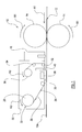
- Figure 1 is a schematic of the main elements of a first embodiment of apparatus according to the invention from the side;
- Figure 2 is a schematic of the apparatus of Figure 1 from above;
- Figure 3 is a block diagram of the control of the apparatus according to the invention;
- Figure 4 is a schematic of the main elements of a second embodiment of apparatus according to the invention from the side;
- Figure 5 is a schematic of the main elements of a third embodiment of apparatus according to the invention from the side; and
- Figure 6 is a schematic of a memory tag and data write device as incorporated in any embodiment of the invention.
-
- Referring to Figures 1 and 2
apparatus 10 for printing and memory tag placement onto a base medium, in thiscase sheet paper 12, is illustrated. For simplicity only those parts of theapparatus 10 which need to be shown to describe the invention are illustrated. - The
apparatus 10 includes much known technology from the prior art of printers which is not described here. However, theapparatus 10 includespaper feed rollers 14 which are driven to rotate as indicated by arrows R1 to feed thepaper sheets 12 through theapparatus 10 along a first axis in the direction indicated by arrows A1. - The
apparatus 10 further includes aprint head 16, which in this example is of ink jet form, mounted on aprint head carriage 18 which extends across theapparatus 10 substantially perpendicular to the axis A1. Theprint head 16 is moveable back and forth along theprint head carriage 18, in known manner. Thus theprint head 16 is moveable back and forth along a second axis indicated by arrows A2, substantially perpendicular to the axis A1, to enable theprint head 16 to access most of theupper surface 12a of thepaper sheet 12 as it moves through theapparatus 10, and thus to print anywhere on that accessible area ofsurface 12a as required. - The
apparatus 10 also includes amemory tag dispenser 20 which in this embodiment is connected to theprint head 16 for movement back and forth along theprint head carriage 18 with theprint head 16. Thus thememory tag dispenser 20 is moveable back and forth along a third axis indicated by arrows A3, substantially perpendicular to the axis A1, and parallel to the axis A2, to enable thememory tag dispenser 20 to apply memory tags to anywhere on the accessible area ofsurface 12a, as will be described further below. - The
memory tag dispenser 20 includes asupply 22 ofmemory tags 24 removably secured to asubstrate 26 by appropriate adhesive, thememory tags 24 having further adhesive on the faces opposite thesubstrate 26. A substrate guidepath comprising rollers substrate 26 and thus thememory tags 24 through thedispenser 20.Roller 36 is driven to rotate in the direction of arrow R2 to pull thesubstrate 26 along the guide path from thesupply 22 onroller 28. Thememory tag dispenser 20 further includes adata write station 38 and a memorytag application station 40 located adjacent to the substrate guide path such that thesubstrate 26 passes between thedata write station 38 and the memorytag application station 40 and thepaper sheet 12. - The
data writing station 38 is used to write data to thememory tags 24, in known manner, whilst they are still on thesubstrate 26, shortly before they are applied to thepaper sheet 12. Then, at the memory tag application station 40 a reciprocating member (not shown) can on command push thesubstrate 26, behind the location of amemory tag 24 to be applied to thepaper sheet 12, downwards and thus apply thememory tag 24, by means of the adhesive on it's face opposite thesubstrate 26, to thepaper sheet 12. Theempty substrate 26, following the removal of the memory tags 24, is wound ontoroller 36 for later disposal when afresh supply 22 is loaded into thememory tag dispenser 20 if appropriate, or replacement of the wholememory tag dispenser 20 if it is a disposable unit as for the toner cartridges in most printers. - The method of operation of the
apparatus 10 will now be described, with reference also to Figure 3. Theapparatus 10 includes amain processor 42 which receives instruction signals from ahost computer 44, including the details of what to print, where to print it, what data to write to the memory tag ortags 24 to be applied to thepaper sheet 12, and where on thepaper sheet 12 the memory tag ortags 24 are to be applied. Themain processor 42 sends command signals as required to themechanics controller 46, which controls all the mechanical operations of the apparatus, (i.e. thepaper feed rollers 14, the movement of theprint head 16 andmemory tag dispenser 20 along theprint head carriage 18 and the operation of memory tag dispenser 20), to theprint head 16 and to the data writestation 38. Thus thepaper sheet 12 is fed through theapparatus 10 and has the required information printed on it'supper surface 12a. At the same time the required memory tags 24 have the necessary data written to them at the data writestation 38 prior to being moved to thetag application station 40 where they are applied to theupper surface 12a of thepaper sheet 12 in the required location(s). - The manner of co-ordination of the printing, data writing and tag application processes will depend on a number of factors. If, for example, the memory tags 24 are only to be applied adjacent the top and/or bottom of the
paper sheet 12 then the data writing and tag application processes can take place before and/or after the printing. This would avoid the necessity for the printing process to be interrupted, and would make the co-ordination simpler. Further, when implemented with an inkjet printer, which in general requires a pause, after printing has been completed before the paper sheet is ejected, to allow the ink to dry, the data writing and tag application processes could conveniently take place during this pause for memory tags applied adjacent the bottom of the paper sheet. - It is likely that the memory tags 24 will be read in future both by further apparatus which can scan the
paper sheet 12 to locate the memory tags 24 and by hand held readers. Thus in order to assist users in the future to locate the memory tags 24 on thepaper sheet 12 the memory tags 24 may be applied to thepaper sheet 12 on top of printed icons which can be readily identified by users. - Referring now to Figure 6 the basic operation of the memory tags 24 and of the data write
station 38 will be described. Thememory tag 24 includes an antenna coil L1 and a capacitor C1 connected in parallel therewith to form a resonant circuit. It further includes a memory M and processing and power circuit P1. The data writestation 38 includes an antenna coil L2 and a capacitor C2 in parallel therewith to form a resonant circuit, and a processing and signal generating circuit P2. - A signal generator with in P2 generates a signal at the chosen frequency, such as 2.45GHz, this is applied to the antenna coil L2 and thus generates an electro-magnetic field which, provided the
memory tag 24 is sufficiently close to the data writedevice 38, penetrates the antenna coil L1 of thememory tag 24. By induction a voltage is thus generated in the antenna coil L1, this is rectified in circuit P1 and used to power thememory tag 24. The capacitance of the capacitors C1 and C2 is selected such that the resonant circuits are both resonant at the frequency generated by the signal generator, in order to maximise transmitted signal strength and received signal. - When data is to be written to the
memory tag 24 by the data writedevice 38 the radio frequency signal generated in P2 is modulated, e.g. amplitude modulated, with the data before being applied to the antenna coil L2 and transmitted. The signal received by thememory tag 24 by inductive coupling thus both powers thememory tag 24 and communicates with it, the circuit P1 separating the data signal from the carrier and passing data for storage to the memory M. - Similarly, if data is to be read from the
memory tag 24 the circuit P1 applies a signal indicative of the data to the antenna coil L1 which is detected, as a result of the inductive coupling, by antenna coil L2 and deciphered in circuit P2 before being passed from the data writedevice 38 tomain processor 42 of theapparatus 10. This signal may for example be transmitted using load modulation. In RFID systems such as this the power consumed by thememory tag 24 can be measured as a drop in voltage across the internal resistance of the antenna coil L2 of the data writedevice 38. A load resistance within the circuit P1 may be switched on and off, thus altering the power consumed by thememory tag 24 which is then detected as an amplitude modulation of the voltage across the antenna coil L2 of the data writedevice 38. - The
apparatus 10 has been described as appropriate for use withpaper sheets 12. However, embodiments of the invention may also be constructed for use with other base media, for example paper in fan fold or roll form, other sheet material, or indeed boxes or other packages passing underneath, rather than through theapparatus 10, on some kind of conveyor. - The data write
station 38 may, in addition to writing the data to the memory tags 24, also conduct a read operation to check that the data has written successfully before thememory tag 24 is applied to the base medium. Alternatively, particularly if the apparatus 10' is operating at high speed, a separatedata check station 50 may be included in apparatus 10', this would be conveniently located between the data writestation 38 and the memorytag application station 40, within the memory tag dispenser 20', as shown in figure 4 (where parts common to theapparatus 10 of Figure 1 are like referenced). - A further alternative, for some very limited applications, is for the
supply 22 ofmemory tags 24 to be pre-written with data when loaded into theapparatus 10. Clearly in such embodiments there would be no requirement for the inclusion of the data writestation 38 within thememory tag dispenser 20" of the apparatus, and such asimplified apparatus 10" is shown in Figure 5 (where parts common to theapparatus 10 of Figure 1 are like referenced). - Although the
print head 16 is described as being of ink jet form, the invention can be implemented with many different forms of print head and indeed many different forms of printer. For some forms of printer with moveable print heads it may be appropriate for the tag dispenser to be moveable independently of the print head, rather than these units being connected together for movement as one. The invention may also be implemented in printers in which the print head is not movable, such as laser printers. All such embodiments still fall within the scope of this invention. - The apparatus of the invention provides a significant advantage over the prior art in that more than one memory tag can be applied to a single base medium, and they can be applied to a large area of the base medium, i.e. that which is accessible to the memory tag dispenser. With the movement of the base medium through the apparatus and the movement of the tag dispenser within the apparatus the accessible area of the base medium is generally most of the area of the base medium, with just the boundaries not being accessible as for most printers.
Claims (19)
- Apparatus (10) for printing and memory tag application onto a base medium (12), the apparatus (10) having a print head (16) for printing onto the base medium (12), and a memory tag dispenser (20) movable relative to the base medium (12) for applying memory tags (24) to the base medium at desired locations.
- Apparatus (10) according to claim 1 wherein the print head (16) is movable relative to the base medium (12).
- Apparatus (10) according to claim 1 or 2 wherein the base medium (12) is moved along a first axis (A1) through or past the apparatus (10) and the print head (16) if moveable moves back and forth along a second axis (A2) and the memory tag dispenser (20) moves back and forth along a third axis (A3), the second and third axes (A2, A3) being substantially perpendicular to the first axis (A1).
- Apparatus (10) according to claim 2 or claim 3 as dependent on claim 2 wherein the print head (16) and memory tag dispenser (20) are connected together and move in unison along the second and third axes (A2, A3).
- Apparatus (10) according to any one of the preceding claims wherein the memory tag dispenser (20) includes a supply (22) of memory tags (24) on a flexible substrate (26) and a substrate guide path (28, 30, 32, 34, 36) which takes the substrate (26) past a memory tag application station (40) where memory tags (24) are removed from the substrate (26) and applied to the base medium (12) as required.
- Apparatus (10) according to claim 5 wherein the memory tag application station (40) includes a reciprocating member adapted to apply pressure to the substrate (26) opposite the location of a memory tag (24) pushing the memory tag (24) onto the base medium (12), thus transferring the memory tag (24) from the substrate (26) to the base medium (12).
- Apparatus (10) according to claim 5 or 6 wherein the memory tag dispenser (20) further includes a data write station (38) where data is written to the memory tags (24) and which is located such that the substrate (26) passes it shortly before passing the memory tag application station (40).
- Apparatus (10) according to claim 7 wherein the data write station (38) also reads the memory tags (24) after writing to them to check that the data has written correctly.
- Apparatus (10) according to claim 7 wherein the memory tag dispenser (20) further includes a data check station which the memory tags (24) pass after the data write station (38) and where the memory tags (24) are read and the data checked with that written at the data write station (38).
- Apparatus (10) according to any one of claims 3 to 9 wherein the base medium (12) passes the print head (16) before passing the memory tag dispenser (20).
- Apparatus (10) according to any one of the preceding claims wherein it is adapted to handle base medium (12) in sheet form which passes through the apparatus (10).
- Apparatus according to claim 11 wherein the base medium (12) passes through the apparatus (10) with a surface (12a) towards the print head (16) and the memory tag dispenser (20), and the printing and the memory tag (24) are applied to that surface.
- A method of printing onto a base medium (12) and applying a memory tag (24) to the base medium (12) comprising the steps of:i) feeding the base medium (12) along a first axis (A1) past a print head (16);ii) printing onto the base medium (12);iii) feeding the base medium (12) past a memory tag dispenser (20), andiv) moving the memory tag dispenser (20) relative to the base medium (12) and applying a memory tag (24) to the base medium (12) at a desired location.
- A method according to claim 13 wherein it further comprises the step of moving the print head (16) relative to the base medium (12).
- A method according to claim 14 wherein the movement of the print head (16) relative to the base medium (12) is along a second axis (A2) substantially perpendicular to the first axis (A1).
- A method according to any one of claims 13 to 15 wherein the movement of the memory tag dispenser (20) relative to the base medium is along a third axis (A3) substantially perpendicular to the first axis (A1).
- A method according to any one of claims 13 to 16 wherein it further comprises the step of writing data to the memory tag (24), prior to applying it to the base medium (12).
- A method according to claim 17 wherein it further comprises the step of reading the data on the memory tag (24) and checking it against the data written to it.
- A method according to any one of claims 13 to 18 wherein the memory tag (24) is applied to the base medium (12) at a location printed with a preselected icon.
Applications Claiming Priority (2)
| Application Number | Priority Date | Filing Date | Title |
|---|---|---|---|
| GB0227199 | 2002-11-21 | ||
| GB0227199A GB2395462B (en) | 2002-11-21 | 2002-11-21 | Apparatus for printing and memory tag application and method therefor |
Publications (1)
| Publication Number | Publication Date |
|---|---|
| EP1422068A1 true EP1422068A1 (en) | 2004-05-26 |
Family
ID=9948277
Family Applications (1)
| Application Number | Title | Priority Date | Filing Date |
|---|---|---|---|
| EP03257030A Withdrawn EP1422068A1 (en) | 2002-11-21 | 2003-11-07 | Apparatus for printing and memory tag application and method therefor |
Country Status (4)
| Country | Link |
|---|---|
| US (1) | US7077489B2 (en) |
| EP (1) | EP1422068A1 (en) |
| JP (1) | JP2005001764A (en) |
| GB (1) | GB2395462B (en) |
Cited By (3)
| Publication number | Priority date | Publication date | Assignee | Title |
|---|---|---|---|---|
| WO2005013192A1 (en) | 2003-07-24 | 2005-02-10 | Hewlett-Packard Development Company, L.P. | Print media with attached data storage and method of storing data thereon |
| WO2005102716A1 (en) * | 2004-04-20 | 2005-11-03 | Avery Dennison Corporation | Label printing apparatus |
| WO2006038133A1 (en) * | 2004-10-08 | 2006-04-13 | Illinois Tool Works Inc. | Label applicator system |
Families Citing this family (37)
| Publication number | Priority date | Publication date | Assignee | Title |
|---|---|---|---|---|
| US7227721B1 (en) * | 2003-11-19 | 2007-06-05 | Storage Technology Corporation | Multi-directional cartridge memory antenna designs |
| US7384496B2 (en) * | 2004-02-23 | 2008-06-10 | Checkpoint Systems, Inc. | Security tag system for fabricating a tag including an integrated surface processing system |
| US7407195B2 (en) * | 2004-04-14 | 2008-08-05 | William Berson | Label for receiving indicia having variable spectral emissivity values |
| JP4507701B2 (en) * | 2004-05-26 | 2010-07-21 | ブラザー工業株式会社 | Wireless tag attachment device |
| WO2006016594A1 (en) * | 2004-08-12 | 2006-02-16 | Brother Kogyo Kabushiki Kaisha | Wireless tag information writing device |
| AU2004323369A1 (en) * | 2004-09-17 | 2006-03-23 | Siang Beng Chng | System and method for batch conversion of RFID tag to RFID label |
| US7651031B2 (en) * | 2004-10-25 | 2010-01-26 | William Berson | Systems and methods for reading indicium |
| US7931413B2 (en) * | 2005-01-14 | 2011-04-26 | William Berson | Printing system ribbon including print transferable circuitry and elements |
| US7728726B2 (en) * | 2005-01-14 | 2010-06-01 | William Berson | Radio frequency identification labels |
| US7621451B2 (en) * | 2005-01-14 | 2009-11-24 | William Berson | Radio frequency identification labels and systems and methods for making the same |
| US7619520B2 (en) * | 2005-01-14 | 2009-11-17 | William Berson | Radio frequency identification labels and systems and methods for making the same |
| JP2006209497A (en) * | 2005-01-28 | 2006-08-10 | Seiko Epson Corp | Rfid tag, print sheet, printer device and rfid system |
| GB2422692B (en) * | 2005-01-31 | 2009-08-12 | Hewlett Packard Development Co | Software updates for electronic appliances |
| DE602006020415D1 (en) * | 2005-03-03 | 2011-04-14 | Toshiba Tec Kk | PRINTER AND IC CHIP COMMUNICATION DEVICE |
| US8681368B2 (en) * | 2005-03-29 | 2014-03-25 | Infoprint Solutions Company, Llc | Method for delivering radio frequency identification device control and data signals |
| US20060227366A1 (en) * | 2005-03-29 | 2006-10-12 | International Business Machines Corporation | Method and apparatus for controlling radio frequency identification device apparatus in a printer |
| JP4086052B2 (en) * | 2005-04-25 | 2008-05-14 | コニカミノルタビジネステクノロジーズ株式会社 | IC tag processing apparatus, processing method, and printer |
| JP4596321B2 (en) * | 2005-07-12 | 2010-12-08 | ブラザー工業株式会社 | Radio tag circuit element housing and radio tag information communication apparatus |
| US9272805B2 (en) | 2005-08-19 | 2016-03-01 | Adasa Inc. | Systems, methods, and devices for commissioning wireless sensors |
| US7551087B2 (en) * | 2005-08-19 | 2009-06-23 | Adasa, Inc. | Handheld and cartridge-fed applicator for commissioning wireless sensors |
| US8228198B2 (en) * | 2005-08-19 | 2012-07-24 | Adasa Inc. | Systems, methods, and devices for commissioning wireless sensors |
| JP2007105966A (en) * | 2005-10-13 | 2007-04-26 | Seiko Epson Corp | Image forming apparatus |
| JP2007148919A (en) * | 2005-11-29 | 2007-06-14 | Brother Ind Ltd | Wireless tag information communication device and wireless tag circuit element cartridge |
| WO2007060982A1 (en) * | 2005-11-22 | 2007-05-31 | Brother Kogyo Kabushiki Kaisha | Radio tag information communication device and radio tag circuit element cartridge |
| JP4666218B2 (en) * | 2005-11-30 | 2011-04-06 | ブラザー工業株式会社 | Radio tag information communication device and radio tag circuit element cartridge |
| JP4666156B2 (en) * | 2005-11-22 | 2011-04-06 | ブラザー工業株式会社 | Radio tag information communication device and radio tag circuit element cartridge |
| US20070131781A1 (en) * | 2005-12-08 | 2007-06-14 | Ncr Corporation | Radio frequency device |
| JP2007316973A (en) * | 2006-05-26 | 2007-12-06 | Brother Ind Ltd | Radio tag circuit element cartridge and radio tag information communication equipment |
| US10157368B2 (en) | 2006-09-25 | 2018-12-18 | International Business Machines Corporation | Rapid access to data oriented workflows |
| TWI341494B (en) * | 2007-02-07 | 2011-05-01 | Mstar Semiconductor Inc | Label paper with rfid function and rfid tag writing apparatus |
| US9524460B2 (en) * | 2007-05-30 | 2016-12-20 | Zih Corp. | System for processing media units and an associated media roll |
| US7948384B1 (en) | 2007-08-14 | 2011-05-24 | Mpt, Inc. | Placard having embedded RFID device for tracking objects |
| US9415611B2 (en) * | 2007-12-19 | 2016-08-16 | Zih Corp. | Platen incorporating an RFID coupling device |
| CN106394001A (en) * | 2016-08-29 | 2017-02-15 | 合肥菲力姆数码科技有限公司 | Self-service medical multi-medium printing system |
| WO2020085325A1 (en) * | 2018-10-24 | 2020-04-30 | ソニー株式会社 | Cartridge memory and control method therefor, cartridge, and recording/reproduction system |
| CN110254875A (en) * | 2019-05-27 | 2019-09-20 | 浙江美声智能系统有限公司 | Efficient paper jam labeling device |
| WO2021163318A1 (en) * | 2020-02-12 | 2021-08-19 | Avery Dennison Retail Information Services, Llc | Transfer of rfid inlays from a first substrate to a second substrate |
Citations (2)
| Publication number | Priority date | Publication date | Assignee | Title |
|---|---|---|---|---|
| EP1076316A2 (en) | 1999-08-11 | 2001-02-14 | EASTMAN KODAK COMPANY (a New Jersey corporation) | A print having information associated with print stored in a memory coupled to the print |
| US6280544B1 (en) | 1999-04-21 | 2001-08-28 | Intermec Ip Corp. | RF tag application system |
Family Cites Families (17)
| Publication number | Priority date | Publication date | Assignee | Title |
|---|---|---|---|---|
| DE3886510T3 (en) * | 1987-12-16 | 2006-02-23 | Melea Ltd. | Method and system for local fluid assisted injection molding and body made thereby. |
| JPH01191273A (en) * | 1988-01-26 | 1989-08-01 | Toshiba Corp | Picture data compressing method |
| JPH02185581A (en) * | 1989-01-13 | 1990-07-19 | Oki Electric Ind Co Ltd | Double side self-adhesive tape and method for sticking double side self-adhesive sheet therewith |
| US5497140A (en) * | 1992-08-12 | 1996-03-05 | Micron Technology, Inc. | Electrically powered postage stamp or mailing or shipping label operative with radio frequency (RF) communication |
| EP0899705B2 (en) * | 1994-05-10 | 2006-03-22 | Meto International GmbH | Method of producing a sheet of security tags |
| FR2760209B1 (en) * | 1997-03-03 | 1999-05-21 | Ier | METHOD AND SYSTEM FOR ISSUING IDENTIFICATION TAGS |
| JP3917262B2 (en) | 1997-09-19 | 2007-05-23 | 株式会社東芝 | Issuing processing method and issuing processing apparatus for wireless information storage medium |
| JPH1191273A (en) | 1997-09-19 | 1999-04-06 | Toshiba Corp | Wireless information storing medium |
| US6019865A (en) * | 1998-01-21 | 2000-02-01 | Moore U.S.A. Inc. | Method of forming labels containing transponders |
| US5897741A (en) * | 1998-02-09 | 1999-04-27 | Premark Feg L.L.C. | Apparatus for applying security tags to labels |
| US6163260A (en) * | 1998-12-10 | 2000-12-19 | Intermec Ip Corp. | Linerless label tracking system |
| US6645327B2 (en) * | 1999-04-21 | 2003-11-11 | Intermec Ip Corp. | RF tag application system |
| JP4129854B2 (en) * | 2000-08-07 | 2008-08-06 | 東芝テック株式会社 | Printer with RF-ID label creation function |
| JP2002123805A (en) * | 2000-10-17 | 2002-04-26 | Dainippon Printing Co Ltd | Label with noncontact ic tag |
| JP2002207984A (en) * | 2001-01-09 | 2002-07-26 | Dainippon Printing Co Ltd | Label printing system and printer |
| US20030061947A1 (en) * | 2001-10-01 | 2003-04-03 | Hohberger Clive P. | Method and apparatus for associating on demand certain selected media and value-adding elements |
| US8428717B2 (en) * | 2003-10-14 | 2013-04-23 | Medtronic, Inc. | Method and apparatus for monitoring tissue fluid content for use in an implantable cardiac device |
-
2002
- 2002-11-21 GB GB0227199A patent/GB2395462B/en not_active Expired - Fee Related
-
2003
- 2003-10-31 US US10/697,031 patent/US7077489B2/en active Active
- 2003-11-07 EP EP03257030A patent/EP1422068A1/en not_active Withdrawn
- 2003-11-21 JP JP2003391798A patent/JP2005001764A/en active Pending
Patent Citations (2)
| Publication number | Priority date | Publication date | Assignee | Title |
|---|---|---|---|---|
| US6280544B1 (en) | 1999-04-21 | 2001-08-28 | Intermec Ip Corp. | RF tag application system |
| EP1076316A2 (en) | 1999-08-11 | 2001-02-14 | EASTMAN KODAK COMPANY (a New Jersey corporation) | A print having information associated with print stored in a memory coupled to the print |
Cited By (5)
| Publication number | Priority date | Publication date | Assignee | Title |
|---|---|---|---|---|
| WO2005013192A1 (en) | 2003-07-24 | 2005-02-10 | Hewlett-Packard Development Company, L.P. | Print media with attached data storage and method of storing data thereon |
| WO2005102716A1 (en) * | 2004-04-20 | 2005-11-03 | Avery Dennison Corporation | Label printing apparatus |
| WO2006038133A1 (en) * | 2004-10-08 | 2006-04-13 | Illinois Tool Works Inc. | Label applicator system |
| US7193517B2 (en) | 2004-10-08 | 2007-03-20 | Illinois Tool Works Inc. | Label applicator system |
| CN101027217B (en) * | 2004-10-08 | 2010-10-06 | 伊利诺斯器械工程公司 | Label applicator system |
Also Published As
| Publication number | Publication date |
|---|---|
| GB0227199D0 (en) | 2002-12-24 |
| GB2395462B (en) | 2006-04-05 |
| GB2395462A (en) | 2004-05-26 |
| JP2005001764A (en) | 2005-01-06 |
| US20040141790A1 (en) | 2004-07-22 |
| US7077489B2 (en) | 2006-07-18 |
Similar Documents
| Publication | Publication Date | Title |
|---|---|---|
| US7077489B2 (en) | Apparatus for printing and memory tag application and method therefor | |
| EP1422656B1 (en) | Apparatus for printing, data writing to memory tags and data reading from memory tags, and methods therefor | |
| JP3953389B2 (en) | Recording device | |
| US7646303B2 (en) | Detector | |
| JP4141446B2 (en) | Physical objects with memory tags and devices for writing and using such physical objects | |
| JP4600742B2 (en) | Print head and tag label producing apparatus | |
| EP1796022B1 (en) | Wireless tag circuit element container and tag label creating apparatus | |
| US7602295B2 (en) | Radio-communication apparatus and method for enabling radio-communication between radio-communication apparatus and data carrier | |
| CN107555227B (en) | Medium processing device | |
| US6739691B2 (en) | Method and apparatus for preventing theft of replaceable printing components | |
| JP2003326741A (en) | Inkjet recorder | |
| JP2003296669A (en) | Rf-id communication device, recorder, program, control method and radio communication system | |
| JP5555671B2 (en) | COMMUNICATION DEVICE, PARAMETER SETTING METHOD FOR THE DEVICE, AND PARAMETER SETTING PROGRAM | |
| JP4837625B2 (en) | Image forming apparatus and image forming method | |
| JP2004058362A (en) | Recorder | |
| US8205799B2 (en) | Physical object with memory tag and apparatus for use with such objects | |
| JP4014852B2 (en) | Non-contact IC writer mounted recording device | |
| JP2003150909A (en) | Recorder | |
| JP2005238619A (en) | Image forming apparatus | |
| JP2021079558A (en) | Recording device | |
| JP2008052515A (en) | Recording medium sequence and generation method thereof | |
| KR20210134832A (en) | Drop On Demand Card Printer With Ink Tray | |
| JP2005254730A (en) | Recording device, recording control system and recording control program | |
| JP2006035798A (en) | Image recorder |
Legal Events
| Date | Code | Title | Description |
|---|---|---|---|
| PUAI | Public reference made under article 153(3) epc to a published international application that has entered the european phase |
Free format text: ORIGINAL CODE: 0009012 |
|
| AK | Designated contracting states |
Kind code of ref document: A1 Designated state(s): AT BE BG CH CY CZ DE DK EE ES FI FR GB GR HU IE IT LI LU MC NL PT RO SE SI SK TR |
|
| AX | Request for extension of the european patent |
Extension state: AL LT LV MK |
|
| 17P | Request for examination filed |
Effective date: 20040803 |
|
| 17Q | First examination report despatched |
Effective date: 20041029 |
|
| AKX | Designation fees paid |
Designated state(s): DE FR GB |
|
| STAA | Information on the status of an ep patent application or granted ep patent |
Free format text: STATUS: THE APPLICATION IS DEEMED TO BE WITHDRAWN |
|
| 18D | Application deemed to be withdrawn |
Effective date: 20140603 |