EP1420561A2 - System and method for TCP offloading and uploading - Google Patents
System and method for TCP offloading and uploading Download PDFInfo
- Publication number
- EP1420561A2 EP1420561A2 EP03020725A EP03020725A EP1420561A2 EP 1420561 A2 EP1420561 A2 EP 1420561A2 EP 03020725 A EP03020725 A EP 03020725A EP 03020725 A EP03020725 A EP 03020725A EP 1420561 A2 EP1420561 A2 EP 1420561A2
- Authority
- EP
- European Patent Office
- Prior art keywords
- stack
- connection
- hardware
- tcp
- software stack
- Prior art date
- Legal status (The legal status is an assumption and is not a legal conclusion. Google has not performed a legal analysis and makes no representation as to the accuracy of the status listed.)
- Granted
Links
Images


Classifications
-
- H—ELECTRICITY
- H04—ELECTRIC COMMUNICATION TECHNIQUE
- H04L—TRANSMISSION OF DIGITAL INFORMATION, e.g. TELEGRAPHIC COMMUNICATION
- H04L69/00—Network arrangements, protocols or services independent of the application payload and not provided for in the other groups of this subclass
- H04L69/16—Implementation or adaptation of Internet protocol [IP], of transmission control protocol [TCP] or of user datagram protocol [UDP]
- H04L69/161—Implementation details of TCP/IP or UDP/IP stack architecture; Specification of modified or new header fields
-
- H—ELECTRICITY
- H04—ELECTRIC COMMUNICATION TECHNIQUE
- H04L—TRANSMISSION OF DIGITAL INFORMATION, e.g. TELEGRAPHIC COMMUNICATION
- H04L69/00—Network arrangements, protocols or services independent of the application payload and not provided for in the other groups of this subclass
- H04L69/16—Implementation or adaptation of Internet protocol [IP], of transmission control protocol [TCP] or of user datagram protocol [UDP]
- H04L69/163—In-band adaptation of TCP data exchange; In-band control procedures
-
- H—ELECTRICITY
- H04—ELECTRIC COMMUNICATION TECHNIQUE
- H04L—TRANSMISSION OF DIGITAL INFORMATION, e.g. TELEGRAPHIC COMMUNICATION
- H04L69/00—Network arrangements, protocols or services independent of the application payload and not provided for in the other groups of this subclass
- H04L69/12—Protocol engines
Definitions
- FIG. 1 shows a block diagram of a conventional software TCP stack 10.
- the conventional software TCP stack 10 includes a layer 2 (L2) network adapter 20, an L2 network interface driver 30 and a monolithic software stack 40.
- An Ethernet TCP/IP network is coupled to the L2 network adapter 20, which, in turn, is coupled to the L2 network interface driver 30.
- the L2 network interface driver 30 is coupled to the monolithic software stack 40, which, in turn, is coupled to the sockets interface.
- This implementation of the TCP stack may suffer from the significant consumption of CPU processing time and memory bandwidth and may require a substantial amount of memory. As network speeds continue to increase, the memory bandwidth, in particular, may become a bottleneck for the software TCP stack 10. For example, each byte of data may be read or written five times during its processing.
- FIG. 2 shows a block diagram of a conventional hardware TCP stack 50.
- the conventional hardware TCP stack 50 includes a monolithic hardware stack 60 and an L4 network interface driver.
- the Ethernet TCP/IP network is coupled to the monolithic hardware stack 60.
- the monolithic hardware stack 60 is coupled to the L4 network interface driver 70, which, in turn, is coupled to the sockets interface.
- all the code from the software stack is moved to the hardware adapter.
- the hardware stack 50 may also suffer since a large amount of memory must be reserved on the hardware adapter to handle all the data that the stack has promised to take. A rough estimate of the memory size may be ascertained by multiplying the TCP window size by the number of connections.
- Another problem with the hardware implementation is that the full TCP stack, as implemented by the software stack, must be done in the hardware stack, thereby increasing code size and decreasing performance.
- the present invention may provide a multiple stack system including a software stack and a hardware stack.
- the software stack may be adapted to process a first set of TCP packet streams.
- the hardware stack may be adapted to process a second set of TCP packet streams and may be coupled to the software stack.
- the software stack may be adapted to offload one or more TCP connections to the hardware stack.
- the hardware stack may be adapted to upload one or more TCP connections to the software stack.
- the software stack and the hardware stack may process one or more TCP connections concurrently.
- the present invention may provide a method that offloads and uploads in a multiple stack system.
- the method may include one or more of the following: processing one or more TCP connections on a software stack; processing one or more TCP connections on a hardware stack, the processing of the hardware stack occurring concurrently with the processing of the software stack; offloading a first TCP connection from the software stack to the hardware stack; and uploading a second TCP connection from the hardware stack to the software stack.
- One or more of the embodiments according to the present invention may provide for a multiple stack environment in which a portion of a first stack may be run, in parallel, with a second stack. Some connections may be offloaded and uploaded on the fly between the first stack and the second stack.
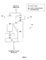
- FIG. 3 shows an embodiment of a multiple stack system according to the present invention.
- the multiple stack system may include, for example, a dual stack system 80.
- the dual stack system 80 may include, for example, a software stack 90 and a hardware stack 100.
- the dual stack system 80 may also include, for example, a path 160 that may be used to offload and/or to upload signaling between the software stack 90 and the hardware stack 100.
- the software stack 90 may include, for example, an L2 network adapter 110, an L2 network interface driver 120 and a full stack implementation 130.
- the Ethernet TCP/IP network may be coupled to the L2 network adapter 110, which, in turn, may be coupled to the L2 network interface driver 120.
- the L2 network interface driver 120 may be coupled to the full stack implementation 130, which, in turn, may be coupled to the sockets interface.
- the hardware stack 100 may include, for example, an accelerated partial stack implementation 140 and an L4 network interface driver 150.
- the accelerated partial stack implementation 140 may include its own L2 network adapter, may be integrated, at least in least in part, with the L2 network adapter 110 or may be coupled to the L2 network adapter 110.
- the Ethernet TCP/IP network may be coupled to the accelerated partial stack implementation 140 possibly via an L2 network adapter.
- the accelerated partial stack implementation 140 may be coupled to the L4 network interface driver 150, which, in turn, may be coupled to the sockets interface.
- FIG. 4 shows a flow chart illustrating an embodiment of a process that determines whether to offload a connection according to the present invention.
- query 170 it may be determined whether a connection is long-lived. In one example, whether a connection is long-lived may be determined from a port number of the established link. Some port numbers are well known and reserved for particular types of connections. Furthermore, system administrator "hints" may be set to assist with the determination whether the connection is a long-lived connection. If, from the port number, it is determined that the connection is long-lived, then the process, in step 210, may offload the connection or may designate the connection for offloading, for example, from the software stack 90 to the hardware stack 100. The process is then complete.
- the connection may also be determined to be long-lived if the connection has been established for a long period of time. On the other hand, if it is determined that the connection is not long-lived (e.g., the port number indicates an HTTP connection), then, in query 180, it may be determined whether the connection is a high bandwidth connection. A connection in the software stack 90 that may be moving a large amount of traffic should be designated for download. Past network usage may be a useful indicator for future network usage of the connection. If the connection is a high bandwidth connection, then, in step 210, the connection may be offloaded or may be designated for offload. If the connection is not a high bandwidth connection, then, in query 190, it may be determined whether the connection desires low latency.
- the connection may be determined whether the connection desires low latency.
- Well-known numbers e.g., port numbers, etc.
- An offload adapter may provide lower latency than a software stack. If low latency is desired, then, in step 210, the connection may be offloaded or may be designated for offload. If low latency is not desired, then, in query 200, it may be determined whether the connection may bypass the kernel. Some connections may be established through, for example, an application interface other than the standard sockets interface. The use of different application interfaces may be easily detected. If the kernel can be bypassed, then, in step 210, the connection may be offloaded or may be designated for offload.
- the application may use a higher level of offload beyond the normal TCP (sockets) connections. If the kernel cannot be bypassed, then the process ends.
- the queries 170-200 are merely examples of factors that may be considered in determining whether a connection should be offloaded or designated for offload. Other factors may be considered in addition to or instead of one or more of the above-described considerations.
- FIG. 5 shows a flow chart illustrating an embodiment of a process that determines whether to upload a connection according to the present invention.
- query 220 it may be determined whether data received from the wire is out of order for the connection. Out-of-order data may need additional work and may use up substantial adapter resources. If a particular connection is persistently out of order, then, in step 250, the connection may be uploaded or designated for upload, for example, from hardware stack 100 to software stack 90. If the particular connection is out of order, then, in query 230, it may be determined whether repeated timeouts occur. A connection that times out repeatedly may not need high performance and should be uploaded. If the connection repeatedly times out, then, in step 250, the connection may be uploaded or may be designated for upload.
- connection may be determined whether the connection is a low bandwidth connection. Connections that are not moving large amounts of data may not efficiently be using the resources of the adapter. Accordingly, low bandwidth connections should be uploaded or designated for upload. If the connection is a low bandwidth connection, then, in step 250, the connection may be uploaded or designated for upload. If the connection is not a low bandwidth connection, then the process may be complete. In one embodiment, the connection may thus remain offloaded.
- the queries 220-240 are merely examples of factors that may be considered in determining whether a connection should be uploaded or designated for upload. Other factors may be considered in addition to or instead of one or more of the above-described considerations.
- connection information may be collected.
- the full stack implementation 130 of the software stack 90 may collect information about the connection including, for example, connection variables, states and settings.
- the collected information may include details such as, for example, IP addresses, TCP ports, window sizes, etc.
- the collected connection information may be passed to the accelerated partial stack implementation 140 via, for example, the path 160.
- step 280 resources in the accelerated partial stack implementation 140 may be allocated by the accelerated partial stack implementation 140.
- the received information including, for example, the collected connection variables may be checked and, based upon the check, storage and other resources may be set aside for the connection. Static information about the connection may be saved in the accelerated partial stack resources.
- query 290 it may be determined whether an allocation failure has occurred. An allocation failure may occur, for example, if the required resources are unavailable for allocation. If an allocation failure occurs, then, in step 310, the accelerated partial stack implementation 140 may free the resources that may have been allocated to the connection. In step 320, an offload failure may occur and the process may be complete.
- the accelerated partial stack implementation 140 may notify the full stack implementation 130 or the full stack implementation 130 may determine that an offload failure has occurred. If an allocation failure does not occur, then, in query 300, it may be determined whether a duplicate offload or some other error condition has occurred. If a duplicate offload or some other error condition has occurred, then the process may jump to steps 310 and 320 as described above. If a duplicate offload or some other error condition has not occurred, then, in step 330, the full stack implementation 130 is informed of the successful resource allocation and the lack of a duplicate offload or some other error condition. In step 340, the full stack implementation 130 may collect current state values (e.g., sequence numbers, etc.) of the connection.
- current state values e.g., sequence numbers, etc.
- the software stack 90 may stop processing the connection.
- the full stack implementation 130 may pass the current state values of the connection to the accelerated partial stack implementation 140.
- the current state values of the connection may be loaded into the accelerated partial stack implementation 140.
- the hardware stack 100 e.g., the accelerated partial stack implementation 140
- the hardware stack 100 may begin processing the connection.
- the decision to upload a connection may be made by, for example, the software stack 90, the hardware stack 100 or a user application. Once the decision to upload has been made, a process that uploads the connection may be initiated according to the present invention. An embodiment of the process that uploads the connection is illustrated in FIG. 7.
- the accelerated partial stack implementation 140 may be notified. No notification may be needed if the accelerated partial stack implementation 140 was the entity that made the decision to upload.
- current state values of the connection may be collected by the accelerated partial stack implementation 140. In one embodiment, once the current state values are collected, the accelerated partial stack implementation 140 may stop processing the connection.
- the current state values of the connection may be passed on to the full stack implementation 130 via, for example, the path 160.
- the full stack implementation 130 may place the offload state back into its structures and, in step 400, start processing the connection.
- the hardware stack 100 e.g., the accelerated partial stack implementation 140
- the hardware stack 100 may free the resources previously allocated for the presently uploaded connection.
- One or more embodiments of the multiple stack system according to the present invention may provide one or more of the advantages as set forth below.
- the hardware stack 100 may be limited in its memory resources. However, since the memory size of the hardware stack 100 is generally smaller than the software stack 90, the hardware stack memory may be integrated with other hardware stack components into a single integrated circuit. A benefit of the smaller memory is that the memory can be accessed very quickly and may provide increase performance.
- the storage may be broken up by storage type so that multiple memories may be used to complete processing, in parallel, of multiple connections, thereby further enhancing performance. Memory bandwidth problems may be reduced.
- Connections that are not good candidates for offload are not offloaded. Connections such as, for example, HTTP 1.0 protocol connections may be so short that the overhead of any offload effort may result in less effective system performance. By allowing the full stack implementation 130 to continue to operate along with the hardware stack 100, these connections may be handled efficiently without decreasing the performance of the system.
- the dual stack system 80 may have no hard limitations of the number of connections supported because, for example, while the heavy traffic connections are off loaded, thousands of idle connections may be tracked by the full stack implementation.
- the dual stack implementation with the capability of offloading and uploading connections may provide a robust fail-over implementation. For example, when an offload adapter is not operating properly such that a connection is not progressing properly, then the connection may be uploaded to the full stack implementation 130, and possibly downloaded to another adapter supported by the system. The other adapter need not be of the same brand or even the same network type.
- a network interface card which may include the hardware stack 100, may be used to indicate repeated timeouts on a particular connection as a hint to the upload-decision maker as to when to upload a connection.
Abstract
Description
Claims (23)
- A multiple stack system, comprising:wherein the software stack is adapted to offload one or more TCP connections to the hardware stack,a software stack adapted to process a first set of TCP packet streams; anda hardware stack adapted to process a second set of TCP packet streams and being coupled to the software stack,
wherein the hardware stack is adapted to upload one or more TCP connections to the software stack, and
wherein the software stack and the hardware stack process one or more TCP connections concurrently. - The system according to claim 1, wherein software stack comprises a monolithic software stack.
- The system according to claim 2, wherein the software stack comprises an L2 network interface driver and an L2 network adapter.
- The system according to claim 1, wherein the hardware stack comprises an accelerated partial stack.
- The system according to claim 4, wherein the hardware stack comprises an L4 network interface driver.
- The system according to claim 1, wherein the software stack or a user application determines whether to offload a particular connection from the software stack to the hardware stack.
- The system according to claim 1, wherein a particular TCP connection is offloaded from the software stack to the hardware stack if the TCP connection is a long-lived connection.
- The system according to claim 1, wherein a particular TCP connection is offloaded from the software stack to the hardware stack if the TCP connection is a high bandwidth connection.
- The system according to claim 1, wherein a particular TCP connection is offloaded from the software stack to the hardware stack if the TCP connection can benefit from a low-latency connection.
- The system according to claim 1, wherein a particular TCP connection is offloaded from the software stack to the hardware stack if the TCP connection can bypass processing associated with an operating system kernel.
- The system according to claim 1, wherein the software stack, the hardware stack or a user application determines whether to upload a particular connection from the hardware stack to the software stack.
- The system according to claim 1, wherein a particular TCP connection is uploaded from the hardware stack to the software stack if the TCP connection comprises out-of-order data.
- The system according to claim 1, wherein a particular TCP connection is uploaded from the hardware stack to the software stack if the TCP connection repeatedly timeouts.
- The system according to claim 1, wherein a particular TCP connection is uploaded from the hardware stack to the software stack if the TCP connection is a low bandwidth connection.
- The system according to claim 1, wherein whether a particular TCP connection is offloaded or is uploaded is dependent upon a dynamic connection environment.
- The system according to claim 1, wherein a particular connection can be offloaded or uploaded on the fly.
- The system according to claim 1, wherein a particular connection can be offloaded for a first time period and then uploaded for a subsequent time period.
- A method for offloading and uploading in a multiple stack system, comprising:processing one or more TCP connections on a software stack;processing one or more TCP connections on a hardware stack, the processing of the hardware stack occurring concurrently with the processing of the software stack;offloading a first TCP connection from the software stack to the hardware stack; anduploading a second TCP connection from the hardware stack to the software stack.
- The method according to claim 18, wherein the first TCP connection is same as second TCP connection.
- The method according to claim 18, wherein the offloading occurs if the first TCP connection is at least one of a long-lived connection and high bandwidth connection.
- The method according to claim 18, wherein the offloading occurs if the first TCP connection desires a low-latency connection or can bypass a kernel.
- The method according to claim 18, wherein the uploading occurs if the second TCP connection comprises out-of-order data.
- The method according to claim 18, wherein the uploading occurs if the second TCP connection repeatedly timeouts or is a low bandwidth connection.
Applications Claiming Priority (4)
| Application Number | Priority Date | Filing Date | Title |
|---|---|---|---|
| US41002202P | 2002-09-11 | 2002-09-11 | |
| US410022P | 2002-09-11 | ||
| US298817 | 2002-11-18 | ||
| US10/298,817 US8230090B2 (en) | 2002-09-11 | 2002-11-18 | System and method for TCP offloading and uploading |
Publications (3)
| Publication Number | Publication Date |
|---|---|
| EP1420561A2 true EP1420561A2 (en) | 2004-05-19 |
| EP1420561A3 EP1420561A3 (en) | 2004-06-02 |
| EP1420561B1 EP1420561B1 (en) | 2014-11-12 |
Family
ID=31996879
Family Applications (1)
| Application Number | Title | Priority Date | Filing Date |
|---|---|---|---|
| EP03020725.2A Expired - Fee Related EP1420561B1 (en) | 2002-09-11 | 2003-09-11 | System and method for TCP offloading and uploading |
Country Status (2)
| Country | Link |
|---|---|
| US (1) | US8230090B2 (en) |
| EP (1) | EP1420561B1 (en) |
Families Citing this family (5)
| Publication number | Priority date | Publication date | Assignee | Title |
|---|---|---|---|---|
| US7673074B1 (en) * | 2002-10-24 | 2010-03-02 | Emulex Design & Manufacturing Corporation | Avoiding port collisions in hardware-accelerated network protocol |
| GB0408876D0 (en) * | 2004-04-21 | 2004-05-26 | Level 5 Networks Ltd | User-level stack |
| US7817634B2 (en) * | 2006-06-30 | 2010-10-19 | Intel Corporation | Network with a constrained usage model supporting remote direct memory access |
| CN104811432A (en) | 2014-01-29 | 2015-07-29 | 华为技术有限公司 | Data packet processing method and device based on parallel protocol stack instance |
| CN110830381B (en) | 2018-08-10 | 2021-10-26 | 华为技术有限公司 | Congestion control method and related equipment |
Citations (2)
| Publication number | Priority date | Publication date | Assignee | Title |
|---|---|---|---|---|
| US20010037397A1 (en) * | 1997-10-14 | 2001-11-01 | Boucher Laurence B. | Intelligent network interface system and method for accelerated protocol processing |
| US6427171B1 (en) * | 1997-10-14 | 2002-07-30 | Alacritech, Inc. | Protocol processing stack for use with intelligent network interface device |
Family Cites Families (13)
| Publication number | Priority date | Publication date | Assignee | Title |
|---|---|---|---|---|
| US6587884B1 (en) * | 1997-09-10 | 2003-07-01 | Schneider Automation, Inc. | Dual ethernet protocol stack for maximum speed access to a programmable logic controller (PLC) |
| US7237036B2 (en) * | 1997-10-14 | 2007-06-26 | Alacritech, Inc. | Fast-path apparatus for receiving data corresponding a TCP connection |
| US6226680B1 (en) * | 1997-10-14 | 2001-05-01 | Alacritech, Inc. | Intelligent network interface system method for protocol processing |
| US7089326B2 (en) * | 1997-10-14 | 2006-08-08 | Alacritech, Inc. | Fast-path processing for receiving data on TCP connection offload devices |
| US6591302B2 (en) * | 1997-10-14 | 2003-07-08 | Alacritech, Inc. | Fast-path apparatus for receiving data corresponding to a TCP connection |
| US6334155B1 (en) * | 1998-11-17 | 2001-12-25 | International Business Machines Corporation | Method and apparatus for connecting similar stacks without using physical devices |
| US6490615B1 (en) * | 1998-11-20 | 2002-12-03 | International Business Machines Corporation | Scalable cache |
| US7089293B2 (en) * | 2000-11-02 | 2006-08-08 | Sun Microsystems, Inc. | Switching system method for discovering and accessing SCSI devices in response to query |
| US7535913B2 (en) * | 2002-03-06 | 2009-05-19 | Nvidia Corporation | Gigabit ethernet adapter supporting the iSCSI and IPSEC protocols |
| US7627693B2 (en) * | 2002-06-11 | 2009-12-01 | Pandya Ashish A | IP storage processor and engine therefor using RDMA |
| US7647414B2 (en) * | 2002-07-26 | 2010-01-12 | Broadcom Corporation | System and method for managing multiple stack environments |
| US7934021B2 (en) * | 2002-08-29 | 2011-04-26 | Broadcom Corporation | System and method for network interfacing |
| US7191241B2 (en) * | 2002-09-27 | 2007-03-13 | Alacritech, Inc. | Fast-path apparatus for receiving data corresponding to a TCP connection |
-
2002
- 2002-11-18 US US10/298,817 patent/US8230090B2/en active Active
-
2003
- 2003-09-11 EP EP03020725.2A patent/EP1420561B1/en not_active Expired - Fee Related
Patent Citations (2)
| Publication number | Priority date | Publication date | Assignee | Title |
|---|---|---|---|---|
| US20010037397A1 (en) * | 1997-10-14 | 2001-11-01 | Boucher Laurence B. | Intelligent network interface system and method for accelerated protocol processing |
| US6427171B1 (en) * | 1997-10-14 | 2002-07-30 | Alacritech, Inc. | Protocol processing stack for use with intelligent network interface device |
Also Published As
| Publication number | Publication date |
|---|---|
| US8230090B2 (en) | 2012-07-24 |
| US20040049591A1 (en) | 2004-03-11 |
| EP1420561B1 (en) | 2014-11-12 |
| EP1420561A3 (en) | 2004-06-02 |
Similar Documents
| Publication | Publication Date | Title |
|---|---|---|
| CN100456724C (en) | Data input/output request processing method and system | |
| US9088451B2 (en) | System and method for network interfacing in a multiple network environment | |
| US20030046330A1 (en) | Selective offloading of protocol processing | |
| EP3238401B1 (en) | Network extended tcp splicing | |
| JP5364773B2 (en) | System and method for managing a connection between a client and a server | |
| US20030099254A1 (en) | Systems and methods for interfacing asynchronous and non-asynchronous data media | |
| US20060161733A1 (en) | Host buffer queues | |
| US20020107903A1 (en) | Methods and systems for the order serialization of information in a network processing environment | |
| US20020108059A1 (en) | Network security accelerator | |
| US20020107962A1 (en) | Single chassis network endpoint system with network processor for load balancing | |
| US20030097481A1 (en) | Method and system for performing packet integrity operations using a data movement engine | |
| EP1401172A2 (en) | System and method for handling frames in multiple stack environments | |
| US20050141425A1 (en) | Method, system, and program for managing message transmission through a network | |
| JP2003514302A (en) | A system and method for managing client-server connections with independent connections and data buffers. | |
| US20090100195A1 (en) | Methods and Apparatus for Autonomic Compression Level Selection for Backup Environments | |
| US20060206699A1 (en) | Network boot system | |
| CA2584689A1 (en) | Method and system for caching read requests to a shared image in a computer network | |
| US20080288620A1 (en) | Physical Network Interface Selection to Minimize Contention with Operating System Critical Storage Operations | |
| US20080120426A1 (en) | Selective acceleration of transport control protocol (tcp) connections | |
| JP4681337B2 (en) | Fiber channel switch device, information processing system, and login processing method | |
| US8010684B1 (en) | Redirection gateway | |
| US8230090B2 (en) | System and method for TCP offloading and uploading | |
| US7209971B1 (en) | Architecture and run-time environment for network filter drivers | |
| US20080133796A1 (en) | Method, system, and computer program product for dynamically selecting software buffers for aggregation according to current system characteristics | |
| EP1460806A2 (en) | System and method for network interfacing in a multiple network environment |
Legal Events
| Date | Code | Title | Description |
|---|---|---|---|
| PUAI | Public reference made under article 153(3) epc to a published international application that has entered the european phase |
Free format text: ORIGINAL CODE: 0009012 |
|
| PUAL | Search report despatched |
Free format text: ORIGINAL CODE: 0009013 |
|
| AK | Designated contracting states |
Kind code of ref document: A2 Designated state(s): AT BE BG CH CY CZ DE DK EE ES FI FR GB GR HU IE IT LI LU MC NL PT RO SE SI SK TR |
|
| AX | Request for extension of the european patent |
Extension state: AL LT LV MK |
|
| AK | Designated contracting states |
Kind code of ref document: A3 Designated state(s): AT BE BG CH CY CZ DE DK EE ES FI FR GB GR HU IE IT LI LU MC NL PT RO SE SI SK TR |
|
| AX | Request for extension of the european patent |
Extension state: AL LT LV MK |
|
| 17P | Request for examination filed |
Effective date: 20041202 |
|
| AKX | Designation fees paid |
Designated state(s): DE FR GB |
|
| 17Q | First examination report despatched |
Effective date: 20050324 |
|
| RAP1 | Party data changed (applicant data changed or rights of an application transferred) |
Owner name: BROADCOM CORPORATION |
|
| 17Q | First examination report despatched |
Effective date: 20050324 |
|
| APBK | Appeal reference recorded |
Free format text: ORIGINAL CODE: EPIDOSNREFNE |
|
| APBN | Date of receipt of notice of appeal recorded |
Free format text: ORIGINAL CODE: EPIDOSNNOA2E |
|
| APBR | Date of receipt of statement of grounds of appeal recorded |
Free format text: ORIGINAL CODE: EPIDOSNNOA3E |
|
| APAF | Appeal reference modified |
Free format text: ORIGINAL CODE: EPIDOSCREFNE |
|
| APBT | Appeal procedure closed |
Free format text: ORIGINAL CODE: EPIDOSNNOA9E |
|
| GRAJ | Information related to disapproval of communication of intention to grant by the applicant or resumption of examination proceedings by the epo deleted |
Free format text: ORIGINAL CODE: EPIDOSDIGR1 |
|
| GRAP | Despatch of communication of intention to grant a patent |
Free format text: ORIGINAL CODE: EPIDOSNIGR1 |
|
| GRAP | Despatch of communication of intention to grant a patent |
Free format text: ORIGINAL CODE: EPIDOSNIGR1 |
|
| INTG | Intention to grant announced |
Effective date: 20140402 |
|
| INTC | Intention to grant announced (deleted) | ||
| INTG | Intention to grant announced |
Effective date: 20140424 |
|
| GRAS | Grant fee paid |
Free format text: ORIGINAL CODE: EPIDOSNIGR3 |
|
| GRAA | (expected) grant |
Free format text: ORIGINAL CODE: 0009210 |
|
| AK | Designated contracting states |
Kind code of ref document: B1 Designated state(s): DE FR GB |
|
| REG | Reference to a national code |
Ref country code: GB Ref legal event code: FG4D |
|
| REG | Reference to a national code |
Ref country code: DE Ref legal event code: R096 Ref document number: 60346973 Country of ref document: DE Effective date: 20141224 |
|
| REG | Reference to a national code |
Ref country code: DE Ref legal event code: R097 Ref document number: 60346973 Country of ref document: DE |
|
| PLBE | No opposition filed within time limit |
Free format text: ORIGINAL CODE: 0009261 |
|
| STAA | Information on the status of an ep patent application or granted ep patent |
Free format text: STATUS: NO OPPOSITION FILED WITHIN TIME LIMIT |
|
| REG | Reference to a national code |
Ref country code: FR Ref legal event code: PLFP Year of fee payment: 13 |
|
| 26N | No opposition filed |
Effective date: 20150813 |
|
| REG | Reference to a national code |
Ref country code: FR Ref legal event code: PLFP Year of fee payment: 14 |
|
| PGFP | Annual fee paid to national office [announced via postgrant information from national office to epo] |
Ref country code: FR Payment date: 20160926 Year of fee payment: 14 |
|
| REG | Reference to a national code |
Ref country code: DE Ref legal event code: R082 Ref document number: 60346973 Country of ref document: DE Representative=s name: BOSCH JEHLE PATENTANWALTSGESELLSCHAFT MBH, DE Ref country code: DE Ref legal event code: R081 Ref document number: 60346973 Country of ref document: DE Owner name: AVAGO TECHNOLOGIES INTERNATIONAL SALES PTE. LT, SG Free format text: FORMER OWNER: BROADCOM CORP., IRVINE, CALIF., US Ref country code: DE Ref legal event code: R081 Ref document number: 60346973 Country of ref document: DE Owner name: AVAGO TECHNOLOGIES GENERAL IP (SINGAPORE) PTE., SG Free format text: FORMER OWNER: BROADCOM CORP., IRVINE, CALIF., US |
|
| REG | Reference to a national code |
Ref country code: GB Ref legal event code: 732E Free format text: REGISTERED BETWEEN 20171005 AND 20171011 |
|
| REG | Reference to a national code |
Ref country code: FR Ref legal event code: TP Owner name: AVAGO TECHNOLOGIES GENERAL IP PTE. LTD., SG Effective date: 20180228 |
|
| REG | Reference to a national code |
Ref country code: FR Ref legal event code: ST Effective date: 20180531 |
|
| PG25 | Lapsed in a contracting state [announced via postgrant information from national office to epo] |
Ref country code: FR Free format text: LAPSE BECAUSE OF NON-PAYMENT OF DUE FEES Effective date: 20171002 |
|
| REG | Reference to a national code |
Ref country code: DE Ref legal event code: R082 Ref document number: 60346973 Country of ref document: DE Representative=s name: BOSCH JEHLE PATENTANWALTSGESELLSCHAFT MBH, DE Ref country code: DE Ref legal event code: R081 Ref document number: 60346973 Country of ref document: DE Owner name: AVAGO TECHNOLOGIES INTERNATIONAL SALES PTE. LT, SG Free format text: FORMER OWNER: AVAGO TECHNOLOGIES GENERAL IP (SINGAPORE) PTE. LTD., SINGAPORE, SG |
|
| REG | Reference to a national code |
Ref country code: GB Ref legal event code: 732E Free format text: REGISTERED BETWEEN 20190222 AND 20190227 |
|
| PGFP | Annual fee paid to national office [announced via postgrant information from national office to epo] |
Ref country code: GB Payment date: 20190927 Year of fee payment: 17 |
|
| GBPC | Gb: european patent ceased through non-payment of renewal fee |
Effective date: 20200911 |
|
| PG25 | Lapsed in a contracting state [announced via postgrant information from national office to epo] |
Ref country code: GB Free format text: LAPSE BECAUSE OF NON-PAYMENT OF DUE FEES Effective date: 20200911 |
|
| REG | Reference to a national code |
Ref country code: DE Ref legal event code: R079 Ref document number: 60346973 Country of ref document: DE Free format text: PREVIOUS MAIN CLASS: H04L0029060000 Ipc: H04L0065000000 |
|
| PGFP | Annual fee paid to national office [announced via postgrant information from national office to epo] |
Ref country code: DE Payment date: 20210910 Year of fee payment: 19 |
|
| REG | Reference to a national code |
Ref country code: DE Ref legal event code: R119 Ref document number: 60346973 Country of ref document: DE |
|
| PG25 | Lapsed in a contracting state [announced via postgrant information from national office to epo] |
Ref country code: DE Free format text: LAPSE BECAUSE OF NON-PAYMENT OF DUE FEES Effective date: 20230401 |