EP1418977B1 - Microneedles for minimally invasive drug delivery - Google Patents
Microneedles for minimally invasive drug delivery Download PDFInfo
- Publication number
- EP1418977B1 EP1418977B1 EP02739360A EP02739360A EP1418977B1 EP 1418977 B1 EP1418977 B1 EP 1418977B1 EP 02739360 A EP02739360 A EP 02739360A EP 02739360 A EP02739360 A EP 02739360A EP 1418977 B1 EP1418977 B1 EP 1418977B1
- Authority
- EP
- European Patent Office
- Prior art keywords
- substrate
- microneedle
- microneedles
- height
- processor
- Prior art date
- Legal status (The legal status is an assumption and is not a legal conclusion. Google has not performed a legal analysis and makes no representation as to the accuracy of the status listed.)
- Expired - Lifetime
Links
- 238000012377 drug delivery Methods 0.000 title abstract description 6
- 239000012530 fluid Substances 0.000 claims abstract description 55
- 238000004891 communication Methods 0.000 claims abstract description 6
- 239000000758 substrate Substances 0.000 claims description 77
- 238000000034 method Methods 0.000 claims description 52
- XUIMIQQOPSSXEZ-UHFFFAOYSA-N Silicon Chemical compound [Si] XUIMIQQOPSSXEZ-UHFFFAOYSA-N 0.000 claims description 36
- 229910052710 silicon Inorganic materials 0.000 claims description 36
- 239000010703 silicon Substances 0.000 claims description 36
- 238000005530 etching Methods 0.000 claims description 32
- 150000004767 nitrides Chemical class 0.000 claims description 30
- 238000004519 manufacturing process Methods 0.000 claims description 14
- 230000015572 biosynthetic process Effects 0.000 claims description 5
- 229910021420 polycrystalline silicon Inorganic materials 0.000 claims description 3
- 229920005591 polysilicon Polymers 0.000 claims description 3
- 238000000151 deposition Methods 0.000 claims 1
- 239000013060 biological fluid Substances 0.000 abstract 4
- 238000001802 infusion Methods 0.000 abstract 1
- 238000005070 sampling Methods 0.000 abstract 1
- VYPSYNLAJGMNEJ-UHFFFAOYSA-N Silicium dioxide Chemical compound O=[Si]=O VYPSYNLAJGMNEJ-UHFFFAOYSA-N 0.000 description 22
- 230000008569 process Effects 0.000 description 16
- 239000004065 semiconductor Substances 0.000 description 14
- 239000000463 material Substances 0.000 description 8
- 235000012239 silicon dioxide Nutrition 0.000 description 8
- 229910052814 silicon oxide Inorganic materials 0.000 description 8
- 239000000126 substance Substances 0.000 description 8
- 239000003814 drug Substances 0.000 description 7
- 229940079593 drug Drugs 0.000 description 7
- 238000001020 plasma etching Methods 0.000 description 7
- 238000003491 array Methods 0.000 description 6
- 239000000377 silicon dioxide Substances 0.000 description 6
- 229910052581 Si3N4 Inorganic materials 0.000 description 5
- 238000002347 injection Methods 0.000 description 5
- 239000007924 injection Substances 0.000 description 5
- HQVNEWCFYHHQES-UHFFFAOYSA-N silicon nitride Chemical compound N12[Si]34N5[Si]62N3[Si]51N64 HQVNEWCFYHHQES-UHFFFAOYSA-N 0.000 description 5
- WGTYBPLFGIVFAS-UHFFFAOYSA-M tetramethylammonium hydroxide Chemical compound [OH-].C[N+](C)(C)C WGTYBPLFGIVFAS-UHFFFAOYSA-M 0.000 description 5
- KWYUFKZDYYNOTN-UHFFFAOYSA-M Potassium hydroxide Chemical compound [OH-].[K+] KWYUFKZDYYNOTN-UHFFFAOYSA-M 0.000 description 4
- 230000002500 effect on skin Effects 0.000 description 4
- 230000000694 effects Effects 0.000 description 4
- 239000010408 film Substances 0.000 description 4
- 235000012431 wafers Nutrition 0.000 description 4
- 238000001039 wet etching Methods 0.000 description 4
- QTBSBXVTEAMEQO-UHFFFAOYSA-N Acetic acid Chemical compound CC(O)=O QTBSBXVTEAMEQO-UHFFFAOYSA-N 0.000 description 3
- QGZKDVFQNNGYKY-UHFFFAOYSA-N Ammonia Chemical compound N QGZKDVFQNNGYKY-UHFFFAOYSA-N 0.000 description 3
- XPDWGBQVDMORPB-UHFFFAOYSA-N Fluoroform Chemical compound FC(F)F XPDWGBQVDMORPB-UHFFFAOYSA-N 0.000 description 3
- HEMHJVSKTPXQMS-UHFFFAOYSA-M Sodium hydroxide Chemical compound [OH-].[Na+] HEMHJVSKTPXQMS-UHFFFAOYSA-M 0.000 description 3
- 230000003466 anti-cipated effect Effects 0.000 description 3
- 230000004888 barrier function Effects 0.000 description 3
- 229940088623 biologically active substance Drugs 0.000 description 3
- 239000011521 glass Substances 0.000 description 3
- 239000000203 mixture Substances 0.000 description 3
- TXEYQDLBPFQVAA-UHFFFAOYSA-N tetrafluoromethane Chemical compound FC(F)(F)F TXEYQDLBPFQVAA-UHFFFAOYSA-N 0.000 description 3
- KRHYYFGTRYWZRS-UHFFFAOYSA-N Fluorane Chemical compound F KRHYYFGTRYWZRS-UHFFFAOYSA-N 0.000 description 2
- VEXZGXHMUGYJMC-UHFFFAOYSA-N Hydrochloric acid Chemical compound Cl VEXZGXHMUGYJMC-UHFFFAOYSA-N 0.000 description 2
- MHAJPDPJQMAIIY-UHFFFAOYSA-N Hydrogen peroxide Chemical compound OO MHAJPDPJQMAIIY-UHFFFAOYSA-N 0.000 description 2
- NBIIXXVUZAFLBC-UHFFFAOYSA-N Phosphoric acid Chemical compound OP(O)(O)=O NBIIXXVUZAFLBC-UHFFFAOYSA-N 0.000 description 2
- 239000004642 Polyimide Substances 0.000 description 2
- QAOWNCQODCNURD-UHFFFAOYSA-N Sulfuric acid Chemical compound OS(O)(=O)=O QAOWNCQODCNURD-UHFFFAOYSA-N 0.000 description 2
- 238000013459 approach Methods 0.000 description 2
- 230000007423 decrease Effects 0.000 description 2
- 239000007788 liquid Substances 0.000 description 2
- 238000004518 low pressure chemical vapour deposition Methods 0.000 description 2
- 230000000873 masking effect Effects 0.000 description 2
- 229920001721 polyimide Polymers 0.000 description 2
- 239000010453 quartz Substances 0.000 description 2
- 238000011160 research Methods 0.000 description 2
- DDFHBQSCUXNBSA-UHFFFAOYSA-N 5-(5-carboxythiophen-2-yl)thiophene-2-carboxylic acid Chemical compound S1C(C(=O)O)=CC=C1C1=CC=C(C(O)=O)S1 DDFHBQSCUXNBSA-UHFFFAOYSA-N 0.000 description 1
- VHUUQVKOLVNVRT-UHFFFAOYSA-N Ammonium hydroxide Chemical compound [NH4+].[OH-] VHUUQVKOLVNVRT-UHFFFAOYSA-N 0.000 description 1
- GRYLNZFGIOXLOG-UHFFFAOYSA-N Nitric acid Chemical compound O[N+]([O-])=O GRYLNZFGIOXLOG-UHFFFAOYSA-N 0.000 description 1
- 206010033372 Pain and discomfort Diseases 0.000 description 1
- 229910000147 aluminium phosphate Inorganic materials 0.000 description 1
- 229910021529 ammonia Inorganic materials 0.000 description 1
- 239000000908 ammonium hydroxide Substances 0.000 description 1
- 238000000137 annealing Methods 0.000 description 1
- 238000010420 art technique Methods 0.000 description 1
- 238000010923 batch production Methods 0.000 description 1
- 239000008280 blood Substances 0.000 description 1
- 210000004369 blood Anatomy 0.000 description 1
- 230000008859 change Effects 0.000 description 1
- WGLPBDUCMAPZCE-UHFFFAOYSA-N chromium trioxide Inorganic materials O=[Cr](=O)=O WGLPBDUCMAPZCE-UHFFFAOYSA-N 0.000 description 1
- 229940117975 chromium trioxide Drugs 0.000 description 1
- GAMDZJFZMJECOS-UHFFFAOYSA-N chromium(6+);oxygen(2-) Chemical compound [O-2].[O-2].[O-2].[Cr+6] GAMDZJFZMJECOS-UHFFFAOYSA-N 0.000 description 1
- 230000001419 dependent effect Effects 0.000 description 1
- 206010012601 diabetes mellitus Diseases 0.000 description 1
- BUMGIEFFCMBQDG-UHFFFAOYSA-N dichlorosilicon Chemical compound Cl[Si]Cl BUMGIEFFCMBQDG-UHFFFAOYSA-N 0.000 description 1
- 239000007789 gas Substances 0.000 description 1
- 229910052732 germanium Inorganic materials 0.000 description 1
- GNPVGFCGXDBREM-UHFFFAOYSA-N germanium atom Chemical compound [Ge] GNPVGFCGXDBREM-UHFFFAOYSA-N 0.000 description 1
- 238000010438 heat treatment Methods 0.000 description 1
- 238000007654 immersion Methods 0.000 description 1
- 238000010348 incorporation Methods 0.000 description 1
- 230000010365 information processing Effects 0.000 description 1
- 208000014674 injury Diseases 0.000 description 1
- 238000011068 loading method Methods 0.000 description 1
- 238000003754 machining Methods 0.000 description 1
- 238000001465 metallisation Methods 0.000 description 1
- -1 metallization Polymers 0.000 description 1
- 238000002156 mixing Methods 0.000 description 1
- 238000012986 modification Methods 0.000 description 1
- 230000004048 modification Effects 0.000 description 1
- 210000005036 nerve Anatomy 0.000 description 1
- 229910017604 nitric acid Inorganic materials 0.000 description 1
- 229910000069 nitrogen hydride Inorganic materials 0.000 description 1
- 239000011368 organic material Substances 0.000 description 1
- 238000000206 photolithography Methods 0.000 description 1
- 239000002210 silicon-based material Substances 0.000 description 1
- 239000007787 solid Substances 0.000 description 1
- 239000000243 solution Substances 0.000 description 1
- 239000010409 thin film Substances 0.000 description 1
- 230000008733 trauma Effects 0.000 description 1
- 238000007740 vapor deposition Methods 0.000 description 1
- 238000007704 wet chemistry method Methods 0.000 description 1
Images
Classifications
-
- B—PERFORMING OPERATIONS; TRANSPORTING
- B81—MICROSTRUCTURAL TECHNOLOGY
- B81C—PROCESSES OR APPARATUS SPECIALLY ADAPTED FOR THE MANUFACTURE OR TREATMENT OF MICROSTRUCTURAL DEVICES OR SYSTEMS
- B81C1/00—Manufacture or treatment of devices or systems in or on a substrate
- B81C1/00015—Manufacture or treatment of devices or systems in or on a substrate for manufacturing microsystems
- B81C1/00023—Manufacture or treatment of devices or systems in or on a substrate for manufacturing microsystems without movable or flexible elements
- B81C1/00111—Tips, pillars, i.e. raised structures
-
- A—HUMAN NECESSITIES
- A61—MEDICAL OR VETERINARY SCIENCE; HYGIENE
- A61B—DIAGNOSIS; SURGERY; IDENTIFICATION
- A61B5/00—Measuring for diagnostic purposes; Identification of persons
- A61B5/145—Measuring characteristics of blood in vivo, e.g. gas concentration, pH value; Measuring characteristics of body fluids or tissues, e.g. interstitial fluid, cerebral tissue
- A61B5/14507—Measuring characteristics of blood in vivo, e.g. gas concentration, pH value; Measuring characteristics of body fluids or tissues, e.g. interstitial fluid, cerebral tissue specially adapted for measuring characteristics of body fluids other than blood
- A61B5/1451—Measuring characteristics of blood in vivo, e.g. gas concentration, pH value; Measuring characteristics of body fluids or tissues, e.g. interstitial fluid, cerebral tissue specially adapted for measuring characteristics of body fluids other than blood for interstitial fluid
- A61B5/14514—Measuring characteristics of blood in vivo, e.g. gas concentration, pH value; Measuring characteristics of body fluids or tissues, e.g. interstitial fluid, cerebral tissue specially adapted for measuring characteristics of body fluids other than blood for interstitial fluid using means for aiding extraction of interstitial fluid, e.g. microneedles or suction
-
- A—HUMAN NECESSITIES
- A61—MEDICAL OR VETERINARY SCIENCE; HYGIENE
- A61B—DIAGNOSIS; SURGERY; IDENTIFICATION
- A61B5/00—Measuring for diagnostic purposes; Identification of persons
- A61B5/15—Devices for taking samples of blood
- A61B5/150007—Details
- A61B5/150015—Source of blood
- A61B5/150022—Source of blood for capillary blood or interstitial fluid
-
- A—HUMAN NECESSITIES
- A61—MEDICAL OR VETERINARY SCIENCE; HYGIENE
- A61B—DIAGNOSIS; SURGERY; IDENTIFICATION
- A61B5/00—Measuring for diagnostic purposes; Identification of persons
- A61B5/15—Devices for taking samples of blood
- A61B5/150007—Details
- A61B5/150206—Construction or design features not otherwise provided for; manufacturing or production; packages; sterilisation of piercing element, piercing device or sampling device
- A61B5/150221—Valves
-
- A—HUMAN NECESSITIES
- A61—MEDICAL OR VETERINARY SCIENCE; HYGIENE
- A61B—DIAGNOSIS; SURGERY; IDENTIFICATION
- A61B5/00—Measuring for diagnostic purposes; Identification of persons
- A61B5/15—Devices for taking samples of blood
- A61B5/150007—Details
- A61B5/150206—Construction or design features not otherwise provided for; manufacturing or production; packages; sterilisation of piercing element, piercing device or sampling device
- A61B5/150274—Manufacture or production processes or steps for blood sampling devices
- A61B5/150282—Manufacture or production processes or steps for blood sampling devices for piercing elements, e.g. blade, lancet, canula, needle
-
- A—HUMAN NECESSITIES
- A61—MEDICAL OR VETERINARY SCIENCE; HYGIENE
- A61B—DIAGNOSIS; SURGERY; IDENTIFICATION
- A61B5/00—Measuring for diagnostic purposes; Identification of persons
- A61B5/15—Devices for taking samples of blood
- A61B5/150007—Details
- A61B5/150748—Having means for aiding positioning of the piercing device at a location where the body is to be pierced
-
- A—HUMAN NECESSITIES
- A61—MEDICAL OR VETERINARY SCIENCE; HYGIENE
- A61B—DIAGNOSIS; SURGERY; IDENTIFICATION
- A61B5/00—Measuring for diagnostic purposes; Identification of persons
- A61B5/15—Devices for taking samples of blood
- A61B5/150007—Details
- A61B5/150847—Communication to or from blood sampling device
- A61B5/15087—Communication to or from blood sampling device short range, e.g. between console and disposable
-
- A—HUMAN NECESSITIES
- A61—MEDICAL OR VETERINARY SCIENCE; HYGIENE
- A61B—DIAGNOSIS; SURGERY; IDENTIFICATION
- A61B5/00—Measuring for diagnostic purposes; Identification of persons
- A61B5/15—Devices for taking samples of blood
- A61B5/150969—Low-profile devices which resemble patches or plasters, e.g. also allowing collection of blood samples for testing
-
- A—HUMAN NECESSITIES
- A61—MEDICAL OR VETERINARY SCIENCE; HYGIENE
- A61B—DIAGNOSIS; SURGERY; IDENTIFICATION
- A61B5/00—Measuring for diagnostic purposes; Identification of persons
- A61B5/15—Devices for taking samples of blood
- A61B5/150977—Arrays of piercing elements for simultaneous piercing
- A61B5/150984—Microneedles or microblades
-
- A—HUMAN NECESSITIES
- A61—MEDICAL OR VETERINARY SCIENCE; HYGIENE
- A61B—DIAGNOSIS; SURGERY; IDENTIFICATION
- A61B5/00—Measuring for diagnostic purposes; Identification of persons
- A61B5/15—Devices for taking samples of blood
- A61B5/157—Devices characterised by integrated means for measuring characteristics of blood
-
- A—HUMAN NECESSITIES
- A61—MEDICAL OR VETERINARY SCIENCE; HYGIENE
- A61M—DEVICES FOR INTRODUCING MEDIA INTO, OR ONTO, THE BODY; DEVICES FOR TRANSDUCING BODY MEDIA OR FOR TAKING MEDIA FROM THE BODY; DEVICES FOR PRODUCING OR ENDING SLEEP OR STUPOR
- A61M37/00—Other apparatus for introducing media into the body; Percutany, i.e. introducing medicines into the body by diffusion through the skin
- A61M37/0015—Other apparatus for introducing media into the body; Percutany, i.e. introducing medicines into the body by diffusion through the skin by using microneedles
- A61M2037/0023—Drug applicators using microneedles
-
- A—HUMAN NECESSITIES
- A61—MEDICAL OR VETERINARY SCIENCE; HYGIENE
- A61M—DEVICES FOR INTRODUCING MEDIA INTO, OR ONTO, THE BODY; DEVICES FOR TRANSDUCING BODY MEDIA OR FOR TAKING MEDIA FROM THE BODY; DEVICES FOR PRODUCING OR ENDING SLEEP OR STUPOR
- A61M37/00—Other apparatus for introducing media into the body; Percutany, i.e. introducing medicines into the body by diffusion through the skin
- A61M37/0015—Other apparatus for introducing media into the body; Percutany, i.e. introducing medicines into the body by diffusion through the skin by using microneedles
- A61M2037/003—Other apparatus for introducing media into the body; Percutany, i.e. introducing medicines into the body by diffusion through the skin by using microneedles having a lumen
-
- A—HUMAN NECESSITIES
- A61—MEDICAL OR VETERINARY SCIENCE; HYGIENE
- A61M—DEVICES FOR INTRODUCING MEDIA INTO, OR ONTO, THE BODY; DEVICES FOR TRANSDUCING BODY MEDIA OR FOR TAKING MEDIA FROM THE BODY; DEVICES FOR PRODUCING OR ENDING SLEEP OR STUPOR
- A61M37/00—Other apparatus for introducing media into the body; Percutany, i.e. introducing medicines into the body by diffusion through the skin
- A61M37/0015—Other apparatus for introducing media into the body; Percutany, i.e. introducing medicines into the body by diffusion through the skin by using microneedles
- A61M2037/0038—Other apparatus for introducing media into the body; Percutany, i.e. introducing medicines into the body by diffusion through the skin by using microneedles having a channel at the side surface
-
- A—HUMAN NECESSITIES
- A61—MEDICAL OR VETERINARY SCIENCE; HYGIENE
- A61M—DEVICES FOR INTRODUCING MEDIA INTO, OR ONTO, THE BODY; DEVICES FOR TRANSDUCING BODY MEDIA OR FOR TAKING MEDIA FROM THE BODY; DEVICES FOR PRODUCING OR ENDING SLEEP OR STUPOR
- A61M37/00—Other apparatus for introducing media into the body; Percutany, i.e. introducing medicines into the body by diffusion through the skin
- A61M37/0015—Other apparatus for introducing media into the body; Percutany, i.e. introducing medicines into the body by diffusion through the skin by using microneedles
- A61M2037/0053—Methods for producing microneedles
-
- B—PERFORMING OPERATIONS; TRANSPORTING
- B81—MICROSTRUCTURAL TECHNOLOGY
- B81B—MICROSTRUCTURAL DEVICES OR SYSTEMS, e.g. MICROMECHANICAL DEVICES
- B81B2201/00—Specific applications of microelectromechanical systems
- B81B2201/05—Microfluidics
- B81B2201/055—Microneedles
Definitions
- the present invention generally relates to apparatus used for delivering medicinal fluid to a patient, and a method for fabricating such apparatus, and more specifically, to apparatus having an array of microneedles for transdermally delivering a medicinal fluid to a patient in a minimally invasive manner, and a method for fabricating the same.
- a hypodermic needle-tipped syringe is most commonly employed for transcutaneously delivering a medicinal fluid to a patient.
- a significant segment of the population considers receiving an injection delivered with a hypodermic needle to be a painful and unpleasant experience. Although most individuals are required to receive such injections only a few times over the course of their lifetime, those suffering from medical conditions such as diabetes will require much more frequent injections.
- the size of the needle used with common hypodermic syringes is typically a few millimeters in length. These needles, which are referred to as macro-needles, have a relatively large diameter compared to the size of a biological cell. The pain associated with a needle piercing a dermal layer is clearly related to the diameter of the needle. In an attempt to decrease the level of pain an individual experiences when receiving an injection, the use of microneedles has been investigated. Microneedles can be fabricated in lengths that enable the dermal barrier to be penetrated sufficiently deep for drug delivery to occur, but not so deep as to stimulate nerves that cause pain and discomfort.
- microneedles having a diameter measured in micrometers have been developed. The reduced size decreases discomfort and pain to the patient.
- microneedles have been developed. Glass pipettes have been used to fabricate microneedles with a diameter of approximately 20 ⁇ m. These microneedles can be formed by heating a relatively large diameter glass pipette and stretching the pipette until its diameter is reduced to about 20 ⁇ m. Glass microneedles of this size can be used to inject and withdraw fluids from a single cell. However, the stretching technique employed to produce the microneedle is rather crude, and it is difficult to accurately and reproducibly control the size of a microneedle fabricated in this manner. Furthermore, such microneedles are extremely fragile.
- U.S. Patent No. 5,457,041 discloses an array of microneedles extending outwardly from a supporting substrate and having tip portions shaped and dimensioned to both carry a biologically active substance and to pierce and penetrate into target cells within tissue, so that the biological substance is transferred from the tip portion and deposited within the target cells.
- the array of microneedles is fabricated using silicon wafers and photolithographic-based etching techniques. The result is an array of solid microneedles. Any biologically active substance to be delivered by these needles must be loaded onto the tips of the microneedles to effect delivery. Such tip loading is not effective to deliver a precisely metered dose of a biologically active substance.
- U.S. Patent No. 5,591,139 discloses a different type of silicon-based microneedle. Rather than producing an array of needles that extend outwardly from a substrate, this patent discloses fabricating a microneedle that extends parallel to the plane of a silicon substrate. Using a combination of masking and etching techniques, a hollow microneedle is formed, which includes an interface region and a shaft. A shell defining an enclosed channel forms the shaft, which has ports to permit fluid movement.
- the interface region includes microcircuit elements that can be used to provide micro-heaters, micro-detectors or other micro-devices on the microneedle.
- U.S. Patent No. 6,033,928 discloses an array of semiconductor microneedles, each having a diameter sufficiently small to exhibit quantum effects.
- These semiconductor microneedle arrays can be used to provide a semiconductor apparatus with high information-processing functionality and are fabricated by forming a silicon dioxide film on a silicon substrate. Hemispherical grains made of silicon, each having an extremely small diameter, are then deposited on the film by vapor deposition. After annealing the hemispherical grains, the silicon dioxide film is etched using the hemispherical grains as a first dotted mask, thereby forming a second dotted mask comprising the silicon dioxide film. The resulting second dotted mask is used to etch the silicon substrate to a specified depth, thereby forming an aggregate of semiconductor microneedles. Note that drug delivery applications generally do not require a microneedle that is a semiconductor.
- WO 01/49362 discloses a method of forming a needle and a needle having an elongated body formed of a semiconductor material.
- the method of forming a needle includes the step of anisotropically etching a channel into the back side of a semiconductor substrate.
- microneedles that each incorporate a fluid channel through which a controlled volume of fluid can be delivered.
- microneedle arrays would be designed to minimize the breakage of individual needles within the array, a common problem with prior art microneedles.
- a method for fabricating such an array of microneedles that utilizes conventional micro-scale fabrication techniques, such that the size of the microneedles can be accurately and reproducibly controlled.
- a microneedle-based drug delivery system that offers full control over the dosage of the drug delivered by the microneedles. The prior art does not disclose or suggest such an apparatus or method.
- a hollow microneedle for transcutaneously conveying a fluid.
- the microneedle has a generally conical-shaped body, with a beveled, non-coring tip that is able to pierce tissue and a broad base.
- a fluid channel extends through the body connecting the broad base in fluid communication with the tip.
- the height of the microneedle which is the distance from the broad base to the tip, is about the same or substantially less than a width of the broad base.
- the microneedle is fabricated from a silicon-based substrate, using semiconductor fabrication techniques.
- an array of hollow microneedles are fabricated.
- the array includes a substrate with at least one inlet and a plurality of outlets in fluid communication with the at least one inlet.
- the microneedles extend outwardly from the substrate, each being proximate to an outlet through the substrate.
- Each microneedle in the array is generally configured as noted above.
- Another aspect of the present invention is directed to a method of manufacturing a hollow microneedle.
- the method includes the steps of providing a substrate; forming an orifice within the substrate, such that the orifice passes completely through the substrate; and removing a substantial portion of the substrate, leaving a remainder.
- the remainder is disposed around the orifice and is generally conical in shape, so that the orifice is disposed generally along a central axis of the conical shape.
- the step of removing a substantial portion of the substrate preferably bevels a tip of the conical shape.
- the substrate is silicon or polysilicon, and conventional semiconductor fabrication methods are employed for the fabrication process.
- a first mask is formed such that only portions of the substrate corresponding to a desired location of the orifice are exposed.
- the orifice is then etched, and the first mask removed.
- a second mask is formed and a nitride layer in deposited on unmasked areas.
- the second mask is then removed, and the substrate is etched to remove a substantial portion.
- the step of etching the substrate preferably comprises the step of performing an anisotropic etch, and then performing an isotropic etch.
- Another aspect of the present invention is directed toward a method of manufacturing an array of hollow microneedles, which is generally consistent with the method discussed above.
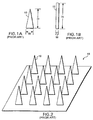
- FIGURE 1A shows a generally conically-shaped microneedle 10, having a width W, measured along its base, and a height H, measured from the base to the tip of the microneedle. Note that width W is substantially less than height H of microneedle 10, and that width W of the base corresponds to the diameter of microneedle 10 at its base.
- a prior art microneedle (like microneedle 10) having a base whose width is approximately 30 ⁇ m and whose height is approximately 150 ⁇ m has been disclosed on the World Wide Web at the address http://mems mirc.gatech.edu/research/biomed.html .
- a microneedle having a base with a width ranging from 0.5 ⁇ m to 10 ⁇ m, and a height of approximately 100 ⁇ m is described in U.S. Patent No. 4,969,468. This patent specifically teaches that the ratio of the height of the microneedle to the width of the base of the microneedle should be on the order of 10 to 1, resulting in a relatively slender microneedle.
- 5,457,041 discloses microneedles whose width at the base varies from 0.5 ⁇ m to 3.0 ⁇ m, and which are 10 ⁇ m to 25 ⁇ m tall. Each of these three sources thus disclose prior art microneedles whose height exceeds the width of their base by a ratio of at least 8:1.
- FIGURE 1B illustrates a generally cylindrically-shaped prior art microneedle 12, whose height H also substantially exceeds its width W, measured at its base.
- U.S. Patent No. 6,033,928 discloses a microneedle shaped like microneedle 12, having a base whose width ranges from 0.002 ⁇ m to 0.05 ⁇ m, and whose height ranges from 0.5 ⁇ m to 2 ⁇ m.
- generally cylindrical microneedle 12 in the prior art have a height to width ratio of at least 4:1.
- the microneedles of the prior art generally are fabricated of a silicon-based material using conventional semi-conductor fabrication techniques.
- a prior art microneedle array 18 shown in FIGURE 2 incorporates a plurality of prior art microneedles 10 from FIGURE 1A. While other microneedles and arrays are disclosed in the prior art, their shape (height to base) characteristics are generally similar to those illustrated in FIGURES 1A, 1B, and to those shown in FIGURE2.
- Prior art microneedles generally tend to be slender "spike” or cylindrically-shaped structures whose height is substantially greater than their width at the base.
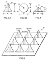
- FIGURE 3A illustrates a microneedle 20 in accord with the present invention.
- microneedle 20 has a base whose width W is substantially equivalent to its height H. In one embodiment, the width and height are about 100 ⁇ m; however, it should be noted that this example is simply exemplary and is not intended to be limiting on the scope of the present invention.
- Microneedle 20 further incorporates a fluid channel 24 and a beveled, non-coring tip 25.
- FIGURE 3B clearly shows that fluid channel 24 passes completely through the microneedle.
- a ratio of height H to width W of microneedle 20 is substantially 1:1, whereas the microneedles of the prior art have height-to-width ratios ranging from 4:1 to 10:1.
- FIGURE 4 illustrates a second embodiment of a microneedle in accord with the present invention.
- Microneedle 22 incorporates a base whose width W exceeds its height H, i.e., its width W is approximately twice its height H.
- the width W is about 100 ⁇ m
- the height H is about 50 ⁇ m, providing a height to width ratio of about 1:2.
- a key feature of microneedle 22 is that its ratio of height-to-width is less than 1:1, thus microneedle 22 has a base that is wider than its height.
- Microneedle 22 further incorporates fluid channel 24', and non-coring tip 25'.
- FIGURE 5 illustrates a microneedle array 26 of a plurality of microneedles 20.
- Each microneedle 20 in the array includes fluid channel 24 and non-coring tip 25, and each microneedle 20 has a height to width ratio of approximately 1:1.
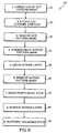
- FIGURE 6 A flowchart 28 in FIGURE 6 illustrates the sequence of logical steps used to fabricate a microneedle needle array in accord with the present invention.
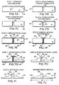
- FIGURES 7A-7I illustrate cross-sectional views of a substrate material during the corresponding process steps in flowchart 28, while FIGURE 7J illustrates a finished microneedle.
- silicon will be a preferred substrate, although other substrates, such as germanium, that can be manipulated using related techniques, might also be used.
- an array containing a plurality of broad base microneedles is preferably manufactured in a batch process, following steps somewhat like those used in semiconductor manufacturing processes. Accordingly, a silicon substrate will typically comprise a four-, six-, or eight-inch silicon wafer on which a plurality of different microneedle arrays are fabricated at a time.
- FIGURES 7A-7J fabrication of only a single microneedle is illustrated in FIGURES 7A-7J.
- the various layers comprising the microneedle are very thin, but for clarity, the dimensions of these layers as shown in the Figures are much exaggerated.
- a Reactive Ion Etching (RIE) process is used to preferentially etch silicon oxide, silicon nitride, or a silicon substrate.
- a typical system includes a parallel plate reactive ion etching configuration with a 5 inch quartz electrode, and a 1 KW, 15 MHz radio frequency (RF) generator.
- RF radio frequency
- Such a system can include a plurality of mass flow controllers, a throttle valve and a controller (to maintain constant pressure), and a high rate turbomolecular vacuum pump.
- RIE can be used to remove layers such as polyimide, silicon nitride, or silicon oxide from silicon substrates such as wafers, wafer pieces, or individual chips.
- Well known processes are available to etch silicon oxide and nitride (e.g., using carbon tetrafluoride, CF 4 ), to etch silicon oxide preferentially to silicon nitride (using CF 4 and fluoroform, CHF 3 ), and to etch silicon preferentially to silicon oxide (using silicon hexafluoride, SF 6 ).
- a commercially available system such as that described above is the Cooke Vacuum Corporation, Model C71/3 Plasma System. Etch rates for most materials are 400-600 angstroms/minute. Etch rates for silicon oxide can be controlled to about +/-3%.
- the RF Frequency of the Cooke system is 14.56 MHz, and the RF power is variable, up to 1000 watts. Process pressures can range from less than 50 to more than 1000 mtorr.
- the upper and lower electrodes, which are quartz, are closed-circuit liquid cooled. Multiple gas mixing is available at the manifold.
- wet etching can also be beneficially employed to perform the etching required to fabricate microneedles in accord with the present invention.
- Wet etching is a technique that utilizes liquid chemicals to remove materials surrounding a device or to delayer thin films from the surface of a substrate. This technique involves immersion of the device or substrate in a pure chemical or chemical mixture for a given amount of time. The time required is dependent on the composition and thickness of the layer to be removed, as well as the etchant and temperature. A succession of chemicals may be required to remove alternate layers on a device or substrate.
- etching can be used to remove organic materials, silicons, polyimides, metallization, polysilicon, or silicon oxide and silicon nitride layers.
- a few of the many chemicals available for etching include: hydrofluoric acid, hydrochloric acid, sulfuric acid, nitric acid, phosphoric acid, acetic acid, hydrogen peroxide, chromium trioxide, sodium hydroxide, potassium hydroxide, ammonium hydroxide, and ammonium fluoride.
- Etching time ranges from 30 seconds to 24 hours, depending on the etching temperature and the composition and thickness of the material to be etched.
- FIGURE 6 the logic starts at a block 30, in which a dot pattern mask is formed on a suitable substrate.
- silicon is a preferred substrate material.
- FIGURE 7A shows a mask 52 that is laid down on the upper surface of a silicon substrate 50.
- Mask 52 incorporates a round orifice 56.
- Orifice 56 is located in a position that corresponds to a desired location for a fluid channel in a microneedle that is being fabricated.
- a plurality of orifices 56 would be formed on a larger portion of substrate 50, each orifice corresponding to the location of a microneedle being fabricated on the substrate material.
- the size (diameter) of the orifices in the dot pattern mask are about the same as that of the fluid channels in the finished microneedle array.
- Mask 52 can be produced using standard photo-lithographic techniques, or using other masking techniques commonly used in the semiconductor industry. It is anticipated that mask 52 will be constructed by applying a layer of silicon dioxide onto silicon substrate 50, and then forming orifice 56 in the layer of silicon dioxide at the desired location.
- the logic moves to a block 32, and by etching the substrate where defined by orifice 56, as is illustrated in FIGURE 7B, a fluid channel 58 is formed. Because the substrate is covered by the dot pattern mask in all areas except those areas defined by orifice 56, the only portion of the substrate that will be etched is the portion corresponding to the location of orifice 56. It is expected that a conventional bulk-machining etching process, such as wet etching using a potassium hydroxide (KOH) solution, can be beneficially employed. In such an etching process, the mask layer is much more resistant to the chemical used for etching than the substrate is, thus the substrate will be completely etched before the mask is removed.
- KOH potassium hydroxide
- the etching process will continue until the substrate has been etched completely through to form fluid channel 58, which passes completely through the microneedle and through the supporting substrate.
- the etching process could be controlled to a particular depth, if a fluid channel that does not completely pass through a substrate material is desired. Because the purpose of the fluid channel is to provide a fluid path between the tip of the microneedle and either a fluid supply or a fluid receiving reservoir (not shown here, see FIGURES 9 and 11), if the etching process does not completely etch through the substrate, an additional step would be required to complete the desired fluid path.
- RIE etching process described above can also be employed to etch the silicon substrate, while leaving the silicon oxide layer intact.
- etching techniques can be beneficially employed in this step, and that the techniques noted above are simply exemplary of a preferred approach, and are not intended to be limiting on the scope of the present invention.
- FIGURE 7C illustrates the result of this step, in which dot pattern mask 52, visible in FIGURES 7A and 7B, has been completely removed from silicon substrate 50.
- FIGURE 7D illustrates this step, in which a nitride pattern mask 60 has been formed on silicon substrate 50. Note the areas of silicon substrate 50 in which no nitride pattern mask has been formed. Specifically, the nitride pattern mask is not formed on the internal surfaces of orifice 58, on the undersurface of silicon substrate 50, or on shoulder areas 62 and 64 around opening into fluid channel 58. In particular, note that shoulder area 62 on one side of the fluid channel is much smaller than shoulder area 64 on the opposite side.
- shoulder area 62 and shoulder area 64 The significance of the difference in size between shoulder area 62 and shoulder area 64 will become clear below, from the discussion of subsequent steps in the fabrication process. It should be noted that this difference in the shoulder areas enables the formation of the beveled non-coring tip in the present invention. It is expected that a layer of silicon dioxide can be beneficially employed to form nitride pattern mask 60.
- FIGURE 7E illustrates the result of the nitride layer growth step, in which a nitride layer 66 is grown. Note that nitride layer 66 covers the undersurface of silicon substrate 50, shoulder areas 62 and 64, and the walls of fluid channel 58.
- One method of growing nitride layer 66 provides a 300-700 angstrom thick layer of nitride, using a low pressure chemical vapor deposition (LPCVD) of dichlorosilane (SiH 2 Cl 2 ) in the presence of ammonia (NH 3 ), at a pressure of about 1 ⁇ 2 Torr and at a temperature of about 820° C.
- LPCVD low pressure chemical vapor deposition
- SiH 2 Cl 2 dichlorosilane
- NH 3 ammonia
- FIGURE 7F illustrates silicon substrate 50, nitride layer 66, orifice 58, and shoulders 62 and 64.
- No mask or nitride layer covers areas 63 on the upper surface of silicon substrate 50. Areas 63 can be preferentially removed by etching, without removing the portions of substrate 50 covered by nitride layer 66. Note that nitride layer 66 at shoulders 62 and 64 mimics the offset pattern defined in nitride mask 60 of FIGURE 7D.
- FIGURE 7G illustrates the result obtained after this seventh step in the process.
- an anisotropic etch is characterized by the formation of sharp, angular boundaries.
- Anisotropic etching can be used to form trenches or side walls that are angular in shape, as opposed to the more rounded etching seen in an isotropic etching process.
- anisotropic etching the side walls etch much more slowly than the surface, resulting in sharp boundaries and enabling the formation of high aspect ratio structures.
- Tetramethylammonium hydroxide (N,N,N-Trimethyl-methanaminium hydroxide, or TMAH) is one of several etchants used to achieve anisotropic etching. Note that sharply defined, angular or beveled surfaces 68 have been formed into silicon substrate 50 of FIGURE 7G. It should be noted that an anisotropic etch is also referred to as a "bevel” etch, while an isotropic etch is also referred to as a "rounding" etch.
- FIGURE 6 illustrates the result obtained after removing the nitride layer.
- isotropic rounding etching is characterized by forming rounded surfaces, such as curved surface 70, as opposed to the more angular surfaces formed in anisotropic etching.
- FIGURE 7J illustrates microneedle 22a as fabricated using the steps described in FIGURES 6 and 7A-7I.
- a ratio of a height H to width W of microneedle 22a is less than 1:2.
- the size and shape of the original silicon substrate 50 in FIGURE 7A can be manipulated to change the ratio of height H to width W in finished microneedle 22a of FIGURE 7J.
- a thicker substrate 50 in FIGURE 7A will result in a microneedle having a greater height H in FIGURE 7J.
- Manipulation of the anisotropic etching step of FIGURE 7G will also effect height H in finished microneedle 22a.
- a short etch time will result in a smaller height H, while a longer etch time will result in a greater height H.
Abstract
Description
- The present invention generally relates to apparatus used for delivering medicinal fluid to a patient, and a method for fabricating such apparatus, and more specifically, to apparatus having an array of microneedles for transdermally delivering a medicinal fluid to a patient in a minimally invasive manner, and a method for fabricating the same.
- There are many medical conditions and procedures in which it is necessary to either deliver a drug to a patient across the dermal barrier, or to withdraw a sample of blood or tissue from a patient across the dermal barrier. A hypodermic needle-tipped syringe is most commonly employed for transcutaneously delivering a medicinal fluid to a patient. A significant segment of the population considers receiving an injection delivered with a hypodermic needle to be a painful and unpleasant experience. Although most individuals are required to receive such injections only a few times over the course of their lifetime, those suffering from medical conditions such as diabetes will require much more frequent injections.
- The size of the needle used with common hypodermic syringes is typically a few millimeters in length. These needles, which are referred to as macro-needles, have a relatively large diameter compared to the size of a biological cell. The pain associated with a needle piercing a dermal layer is clearly related to the diameter of the needle. In an attempt to decrease the level of pain an individual experiences when receiving an injection, the use of microneedles has been investigated. Microneedles can be fabricated in lengths that enable the dermal barrier to be penetrated sufficiently deep for drug delivery to occur, but not so deep as to stimulate nerves that cause pain and discomfort.
- As an alternative to macro-needles, microneedles having a diameter measured in micrometers have been developed. The reduced size decreases discomfort and pain to the patient. Research has demonstrated that silicon microprobes with cross sections on the order of tens of micrometers can penetrate living tissue without causing significant trauma. (K. Najafi, K. D. Wise and T. Mochizuki, "A High-Yield IC-Compatible Multichannel Recording Array," IEEE Micro Trans. on Electron Devices, vol. ED-32, pp. 1206-1211, July 1985, XP002030735.
- Several different types of microneedles have been developed. Glass pipettes have been used to fabricate microneedles with a diameter of approximately 20 µm. These microneedles can be formed by heating a relatively large diameter glass pipette and stretching the pipette until its diameter is reduced to about 20 µm. Glass microneedles of this size can be used to inject and withdraw fluids from a single cell. However, the stretching technique employed to produce the microneedle is rather crude, and it is difficult to accurately and reproducibly control the size of a microneedle fabricated in this manner. Furthermore, such microneedles are extremely fragile.
- U.S. Patent No. 5,457,041 discloses an array of microneedles extending outwardly from a supporting substrate and having tip portions shaped and dimensioned to both carry a biologically active substance and to pierce and penetrate into target cells within tissue, so that the biological substance is transferred from the tip portion and deposited within the target cells. The array of microneedles is fabricated using silicon wafers and photolithographic-based etching techniques. The result is an array of solid microneedles. Any biologically active substance to be delivered by these needles must be loaded onto the tips of the microneedles to effect delivery. Such tip loading is not effective to deliver a precisely metered dose of a biologically active substance. Generally, medical treatment methodologies that include the transdermal injection of drugs into a patient require precisely controlling the amount of drug delivered. Delivery of too little amounts of a drug may not effect the desired result, and too much of the drug can have serious, possibly even fatal, consequences. Therefore, it would be desirable to provide a microneedle-based drug delivery system that offers better control over the dosage of the drug delivered by the microneedles, than this prior art technique.
- U.S. Patent No. 5,591,139 discloses a different type of silicon-based microneedle. Rather than producing an array of needles that extend outwardly from a substrate, this patent discloses fabricating a microneedle that extends parallel to the plane of a silicon substrate. Using a combination of masking and etching techniques, a hollow microneedle is formed, which includes an interface region and a shaft. A shell defining an enclosed channel forms the shaft, which has ports to permit fluid movement. The interface region includes microcircuit elements that can be used to provide micro-heaters, micro-detectors or other micro-devices on the microneedle. While a microneedle incorporating a fluid path is extremely useful, the shaft of the microneedle disclosed in this patent is relatively thin and narrow, and breakage is a concern. Furthermore, incorporation of electronic circuitry in the interface region increases the costs and complexity of these microneedles, and such circuitry is not required for all microneedle applications. Finally, using and manipulating an individual microneedle, as opposed to an array of microneedles, presents other challenges.
- A more recent patent directed to microneedle arrays is U.S. Patent No. 6,033,928, which discloses an array of semiconductor microneedles, each having a diameter sufficiently small to exhibit quantum effects. These semiconductor microneedle arrays can be used to provide a semiconductor apparatus with high information-processing functionality and are fabricated by forming a silicon dioxide film on a silicon substrate. Hemispherical grains made of silicon, each having an extremely small diameter, are then deposited on the film by vapor deposition. After annealing the hemispherical grains, the silicon dioxide film is etched using the hemispherical grains as a first dotted mask, thereby forming a second dotted mask comprising the silicon dioxide film. The resulting second dotted mask is used to etch the silicon substrate to a specified depth, thereby forming an aggregate of semiconductor microneedles. Note that drug delivery applications generally do not require a microneedle that is a semiconductor.
- WO 01/49362 discloses a method of forming a needle and a needle having an elongated body formed of a semiconductor material. The method of forming a needle includes the step of anisotropically etching a channel into the back side of a semiconductor substrate.
- In consideration of the prior art discussed above, it would be desirable to provide an array of microneedles that each incorporate a fluid channel through which a controlled volume of fluid can be delivered. Preferably, such microneedle arrays would be designed to minimize the breakage of individual needles within the array, a common problem with prior art microneedles. It would be desirable to provide a method for fabricating such an array of microneedles that utilizes conventional micro-scale fabrication techniques, such that the size of the microneedles can be accurately and reproducibly controlled. It would be further desirable to provide a microneedle-based drug delivery system that offers full control over the dosage of the drug delivered by the microneedles. The prior art does not disclose or suggest such an apparatus or method.
- In accord with the present invention, a hollow microneedle for transcutaneously conveying a fluid is defined. The microneedle has a generally conical-shaped body, with a beveled, non-coring tip that is able to pierce tissue and a broad base. A fluid channel extends through the body connecting the broad base in fluid communication with the tip.
- The height of the microneedle, which is the distance from the broad base to the tip, is about the same or substantially less than a width of the broad base. The microneedle is fabricated from a silicon-based substrate, using semiconductor fabrication techniques.
- In one embodiment, an array of hollow microneedles are fabricated. The array includes a substrate with at least one inlet and a plurality of outlets in fluid communication with the at least one inlet. The microneedles extend outwardly from the substrate, each being proximate to an outlet through the substrate. Each microneedle in the array is generally configured as noted above.
- Another aspect of the present invention is directed to a method of manufacturing a hollow microneedle. The method includes the steps of providing a substrate; forming an orifice within the substrate, such that the orifice passes completely through the substrate; and removing a substantial portion of the substrate, leaving a remainder. The remainder is disposed around the orifice and is generally conical in shape, so that the orifice is disposed generally along a central axis of the conical shape. The step of removing a substantial portion of the substrate preferably bevels a tip of the conical shape.
- In a preferred method, the substrate is silicon or polysilicon, and conventional semiconductor fabrication methods are employed for the fabrication process. For example, to form an orifice, a first mask is formed such that only portions of the substrate corresponding to a desired location of the orifice are exposed. The orifice is then etched, and the first mask removed. A second mask is formed and a nitride layer in deposited on unmasked areas. The second mask is then removed, and the substrate is etched to remove a substantial portion. The step of etching the substrate preferably comprises the step of performing an anisotropic etch, and then performing an isotropic etch.
- Another aspect of the present invention is directed toward a method of manufacturing an array of hollow microneedles, which is generally consistent with the method discussed above.
- The foregoing aspects and many of the attendant advantages of this invention will become more readily appreciated as the same becomes better understood by reference to the following detailed description, when taken in conjunction with the accompanying drawings, wherein:
- FIGURES 1A and 1B are side elevational views of prior art microneedles;
- FIGURE 2 is an isometric view of an array of prior art microneedles that can be fabricated using techniques common to semiconductor fabrication;
- FIGURE 3A is a side elevational view of a hollow microneedle in accord with the present invention;
- FIGURE 3B is a plan view of the hollow microneedle of FIGURE 3A;
- FIGURE 4 is a side elevational view of another embodiment of a hollow microneedle in accord with the present invention, in which a base of the microneedle is substantially wider than a height of the microneedle;
- FIGURE 5 is schematic view of a plurality of microneedles formed as an array, each microneedle in the array being like that illustrated in FIGURES 3A-3B;
- FIGURE 6 is a flow chart illustrating the sequence of logical steps used to fabricate a hollow microneedle in accord with the present invention;
- FIGURES 7A-7J are schematic representations of the sequence of logical steps used to fabricate a hollow microneedle in accord with the flow chart of FIGURE 6;
- Before discussing the present invention, it will be helpful to consider several examples of prior art microneedles, generally with reference to FIGURES 1 A and 1B. FIGURE 1A shows a generally conically-shaped
microneedle 10, having a width W, measured along its base, and a height H, measured from the base to the tip of the microneedle. Note that width W is substantially less than height H ofmicroneedle 10, and that width W of the base corresponds to the diameter ofmicroneedle 10 at its base. - A prior art microneedle (like microneedle 10) having a base whose width is approximately 30 µm and whose height is approximately 150 µm has been disclosed on the World Wide Web at the address http://mems mirc.gatech.edu/research/biomed.html. Similarly, a microneedle having a base with a width ranging from 0.5 µm to 10 µm, and a height of approximately 100 µm is described in U.S. Patent No. 4,969,468. This patent specifically teaches that the ratio of the height of the microneedle to the width of the base of the microneedle should be on the order of 10 to 1, resulting in a relatively slender microneedle. U.S. Patent No. 5,457,041 discloses microneedles whose width at the base varies from 0.5 µm to 3.0 µm, and which are 10 µm to 25 µm tall. Each of these three sources thus disclose prior art microneedles whose height exceeds the width of their base by a ratio of at least 8:1.
- FIGURE 1B illustrates a generally cylindrically-shaped
prior art microneedle 12, whose height H also substantially exceeds its width W, measured at its base. U.S. Patent No. 6,033,928 discloses a microneedle shaped likemicroneedle 12, having a base whose width ranges from 0.002 µm to 0.05 µm, and whose height ranges from 0.5 µm to 2 µm. Thus, generallycylindrical microneedle 12 in the prior art have a height to width ratio of at least 4:1. - The microneedles of the prior art generally are fabricated of a silicon-based material using conventional semi-conductor fabrication techniques. A prior
art microneedle array 18 shown in FIGURE 2 incorporates a plurality ofprior art microneedles 10 from FIGURE 1A. While other microneedles and arrays are disclosed in the prior art, their shape (height to base) characteristics are generally similar to those illustrated in FIGURES 1A, 1B, and to those shown in FIGURE2. Prior art microneedles generally tend to be slender "spike" or cylindrically-shaped structures whose height is substantially greater than their width at the base. - FIGURE 3A illustrates a microneedle 20 in accord with the present invention. In contrast to the prior art microneedles discussed above,
microneedle 20 has a base whose width W is substantially equivalent to its height H. In one embodiment, the width and height are about 100 µm; however, it should be noted that this example is simply exemplary and is not intended to be limiting on the scope of the present invention.Microneedle 20 further incorporates afluid channel 24 and a beveled,non-coring tip 25. FIGURE 3B clearly shows thatfluid channel 24 passes completely through the microneedle. Note that a ratio of height H to width W ofmicroneedle 20 is substantially 1:1, whereas the microneedles of the prior art have height-to-width ratios ranging from 4:1 to 10:1. By insuring that the microneedles in the present invention have a base that is broad with respect to their height, a stronger microneedle, that is less prone to breakage, is provided. - FIGURE 4 illustrates a second embodiment of a microneedle in accord with the present invention.
Microneedle 22 incorporates a base whose width W exceeds its height H, i.e., its width W is approximately twice its height H. In one embodiment, the width W is about 100 µm, while the height H is about 50 µm, providing a height to width ratio of about 1:2. However, it should be similarly noted that the dimensions of 100 µm and 50 µm are simply exemplary, and are not intended to be limiting on the scope of the present invention. A key feature ofmicroneedle 22 is that its ratio of height-to-width is less than 1:1, thus microneedle 22 has a base that is wider than its height.Microneedle 22 further incorporates fluid channel 24', and non-coring tip 25'. - FIGURE 5 illustrates a
microneedle array 26 of a plurality ofmicroneedles 20. Each microneedle 20 in the array includesfluid channel 24 andnon-coring tip 25, and each microneedle 20 has a height to width ratio of approximately 1:1. - A
flowchart 28 in FIGURE 6 illustrates the sequence of logical steps used to fabricate a microneedle needle array in accord with the present invention. FIGURES 7A-7I illustrate cross-sectional views of a substrate material during the corresponding process steps inflowchart 28, while FIGURE 7J illustrates a finished microneedle. - It is anticipated that photolithography and other techniques developed for use in the semiconductor fabrication industry can be beneficially employed in fabricating individual microneedles and arrays of microneedles in accord with the present invention. Thus, it is anticipated that silicon will be a preferred substrate, although other substrates, such as germanium, that can be manipulated using related techniques, might also be used. In general, an array containing a plurality of broad base microneedles is preferably manufactured in a batch process, following steps somewhat like those used in semiconductor manufacturing processes. Accordingly, a silicon substrate will typically comprise a four-, six-, or eight-inch silicon wafer on which a plurality of different microneedle arrays are fabricated at a time. However, for simplicity, fabrication of only a single microneedle is illustrated in FIGURES 7A-7J. In addition, it will be understood that the various layers comprising the microneedle are very thin, but for clarity, the dimensions of these layers as shown in the Figures are much exaggerated.
- The following etching techniques are expected to be useful in fabricating microneedles in accord with the present invention. A Reactive Ion Etching (RIE) process is used to preferentially etch silicon oxide, silicon nitride, or a silicon substrate. For this purpose, a typical system includes a parallel plate reactive ion etching configuration with a 5 inch quartz electrode, and a 1 KW, 15 MHz radio frequency (RF) generator. Such a system can include a plurality of mass flow controllers, a throttle valve and a controller (to maintain constant pressure), and a high rate turbomolecular vacuum pump. RIE can be used to remove layers such as polyimide, silicon nitride, or silicon oxide from silicon substrates such as wafers, wafer pieces, or individual chips. Well known processes are available to etch silicon oxide and nitride (e.g., using carbon tetrafluoride, CF4), to etch silicon oxide preferentially to silicon nitride (using CF4 and fluoroform, CHF3), and to etch silicon preferentially to silicon oxide (using silicon hexafluoride, SF6).
- A commercially available system such as that described above is the Cooke Vacuum Corporation, Model C71/3 Plasma System. Etch rates for most materials are 400-600 angstroms/minute. Etch rates for silicon oxide can be controlled to about +/-3%. The RF Frequency of the Cooke system is 14.56 MHz, and the RF power is variable, up to 1000 watts. Process pressures can range from less than 50 to more than 1000 mtorr. The upper and lower electrodes, which are quartz, are closed-circuit liquid cooled. Multiple gas mixing is available at the manifold.
- In addition to RIE, wet etching can also be beneficially employed to perform the etching required to fabricate microneedles in accord with the present invention. Wet etching is a technique that utilizes liquid chemicals to remove materials surrounding a device or to delayer thin films from the surface of a substrate. This technique involves immersion of the device or substrate in a pure chemical or chemical mixture for a given amount of time. The time required is dependent on the composition and thickness of the layer to be removed, as well as the etchant and temperature. A succession of chemicals may be required to remove alternate layers on a device or substrate.
- Wet etching can be used to remove organic materials, silicons, polyimides, metallization, polysilicon, or silicon oxide and silicon nitride layers. A few of the many chemicals available for etching include: hydrofluoric acid, hydrochloric acid, sulfuric acid, nitric acid, phosphoric acid, acetic acid, hydrogen peroxide, chromium trioxide, sodium hydroxide, potassium hydroxide, ammonium hydroxide, and ammonium fluoride. Etching time ranges from 30 seconds to 24 hours, depending on the etching temperature and the composition and thickness of the material to be etched.
- Referring to FIGURE 6, the logic starts at a
block 30, in which a dot pattern mask is formed on a suitable substrate. As noted above, silicon is a preferred substrate material. FIGURE 7A shows amask 52 that is laid down on the upper surface of asilicon substrate 50.Mask 52 incorporates around orifice 56.Orifice 56 is located in a position that corresponds to a desired location for a fluid channel in a microneedle that is being fabricated. Note that to fabricate an array of microneedles, a plurality oforifices 56 would be formed on a larger portion ofsubstrate 50, each orifice corresponding to the location of a microneedle being fabricated on the substrate material. Regardless of the number oforifices 56 formed, the size (diameter) of the orifices in the dot pattern mask are about the same as that of the fluid channels in the finished microneedle array. -
Mask 52 can be produced using standard photo-lithographic techniques, or using other masking techniques commonly used in the semiconductor industry. It is anticipated thatmask 52 will be constructed by applying a layer of silicon dioxide ontosilicon substrate 50, and then formingorifice 56 in the layer of silicon dioxide at the desired location. - Once the dot pattern mask has been formed, the logic moves to a
block 32, and by etching the substrate where defined byorifice 56, as is illustrated in FIGURE 7B, afluid channel 58 is formed. Because the substrate is covered by the dot pattern mask in all areas except those areas defined byorifice 56, the only portion of the substrate that will be etched is the portion corresponding to the location oforifice 56. It is expected that a conventional bulk-machining etching process, such as wet etching using a potassium hydroxide (KOH) solution, can be beneficially employed. In such an etching process, the mask layer is much more resistant to the chemical used for etching than the substrate is, thus the substrate will be completely etched before the mask is removed. Preferably, the etching process will continue until the substrate has been etched completely through to formfluid channel 58, which passes completely through the microneedle and through the supporting substrate. However, it should be noted that the etching process could be controlled to a particular depth, if a fluid channel that does not completely pass through a substrate material is desired. Because the purpose of the fluid channel is to provide a fluid path between the tip of the microneedle and either a fluid supply or a fluid receiving reservoir (not shown here, see FIGURES 9 and 11), if the etching process does not completely etch through the substrate, an additional step would be required to complete the desired fluid path. It should also be noted that the RIE etching process described above can also be employed to etch the silicon substrate, while leaving the silicon oxide layer intact. Those of ordinary skill in the art will recognize that a plurality of other etching techniques can be beneficially employed in this step, and that the techniques noted above are simply exemplary of a preferred approach, and are not intended to be limiting on the scope of the present invention. - Once
fluid channel 58 has been etched through the substrate, the logic proceeds to ablock 34, and the dot pattern mask is removed. Removal of the dot pattern mask is the reverse of the etching process, because a chemical that dissolves the mask faster than it dissolves the substrate is used. Such mask removal techniques are well known in the art. FIGURE 7C illustrates the result of this step, in which dotpattern mask 52, visible in FIGURES 7A and 7B, has been completely removed fromsilicon substrate 50. - The logic now proceeds to a
block 36 in FIGURE 6 and the fourth step, which is the formation of a nitride pattern mask. FIGURE 7D illustrates this step, in which anitride pattern mask 60 has been formed onsilicon substrate 50. Note the areas ofsilicon substrate 50 in which no nitride pattern mask has been formed. Specifically, the nitride pattern mask is not formed on the internal surfaces oforifice 58, on the undersurface ofsilicon substrate 50, or onshoulder areas fluid channel 58. In particular, note thatshoulder area 62 on one side of the fluid channel is much smaller thanshoulder area 64 on the opposite side. The significance of the difference in size betweenshoulder area 62 andshoulder area 64 will become clear below, from the discussion of subsequent steps in the fabrication process. It should be noted that this difference in the shoulder areas enables the formation of the beveled non-coring tip in the present invention. It is expected that a layer of silicon dioxide can be beneficially employed to formnitride pattern mask 60. - Once the nitride pattern mask has been completed, the logic proceeds to a
block 38, in which a nitride layer is grown in all areas that have not been covered bynitride pattern mask 60. FIGURE 7E illustrates the result of the nitride layer growth step, in which anitride layer 66 is grown. Note thatnitride layer 66 covers the undersurface ofsilicon substrate 50,shoulder areas fluid channel 58. One method of growingnitride layer 66 provides a 300-700 angstrom thick layer of nitride, using a low pressure chemical vapor deposition (LPCVD) of dichlorosilane (SiH2Cl2) in the presence of ammonia (NH3), at a pressure of about ½ Torr and at a temperature of about 820° C. Those of ordinary skill in the art will recognize that other methods for fabricatingnitride layer 66 can be employed and that the above noted technique is simply exemplary of one preferred approach, but is not intended to be limiting on the scope of the present invention. - After
nitride layer 66 has been grown, the logic moves to ablock 40 in FIGURE 6, in whichnitride pattern 60 is removed to expose those portions ofsilicon substrate 50 not covered withnitride layer 66. FIGURE 7F illustratessilicon substrate 50,nitride layer 66,orifice 58, and shoulders 62 and 64. No mask or nitride layer coversareas 63 on the upper surface ofsilicon substrate 50.Areas 63 can be preferentially removed by etching, without removing the portions ofsubstrate 50 covered bynitride layer 66. Note thatnitride layer 66 atshoulders nitride mask 60 of FIGURE 7D. - After
nitride pattern 60 is removed, the logic moves to ablock 42 in FIGURE 6, in which an anisotropic bevel etch is performed onareas 63. FIGURE 7G illustrates the result obtained after this seventh step in the process. Those skilled in the art will understand that several different etching processes are available for use with silicon substrates. In particular, an anisotropic etch is characterized by the formation of sharp, angular boundaries. Anisotropic etching can be used to form trenches or side walls that are angular in shape, as opposed to the more rounded etching seen in an isotropic etching process. In anisotropic etching, the side walls etch much more slowly than the surface, resulting in sharp boundaries and enabling the formation of high aspect ratio structures. Tetramethylammonium hydroxide (N,N,N-Trimethyl-methanaminium hydroxide, or TMAH) is one of several etchants used to achieve anisotropic etching. Note that sharply defined, angular orbeveled surfaces 68 have been formed intosilicon substrate 50 of FIGURE 7G. It should be noted that an anisotropic etch is also referred to as a "bevel" etch, while an isotropic etch is also referred to as a "rounding" etch. - The logic then moves to a
block 42 in FIGURE 6. In this block,nitride layer 66 is removed. As noted above, either RIE or wet chemical processes can be used to preferentially removenitride layer 66. Furthermore, those of ordinary skill in the art will recognize that other methods of removingnitride layer 66 can alternatively be employed. FIGURE 7H illustrates the result obtained after removing the nitride layer. - Finally the logic proceeds to a
block 44, which indicates that an isotropic rounding etch is performed. Note that becausenitride layer 66 has been removed, shoulders 62 and 64 are no longer protected. Thus, in the isotropic etching process, a portion ofsilicon substrate 50 atshoulders curved surface 70, as opposed to the more angular surfaces formed in anisotropic etching. - FIGURE 7J illustrates microneedle 22a as fabricated using the steps described in FIGURES 6 and 7A-7I. A ratio of a height H to width W of
microneedle 22a is less than 1:2. Note that the size and shape of theoriginal silicon substrate 50 in FIGURE 7A can be manipulated to change the ratio of height H to width W infinished microneedle 22a of FIGURE 7J. Athicker substrate 50 in FIGURE 7A will result in a microneedle having a greater height H in FIGURE 7J. Manipulation of the anisotropic etching step of FIGURE 7G will also effect height H infinished microneedle 22a. A short etch time will result in a smaller height H, while a longer etch time will result in a greater height H. - Although the present invention has been described in connection with the preferred form of practicing it, those of ordinary skill in the art will understand that many modifications can be made thereto within the scope of the claims that follow. Accordingly, it is not intended that the scope of the invention in any way be limited by the above description, but instead be determined entirely by reference to the claims that follow.
Claims (13)
- A hollow microneedle (20) comprising:(a) a generally conical-shaped body having a beveled, non-coring tip (25), said tip (25) being sharp and able to pierce tissue;(b) said conical body including a base having a width formed of a substrate at an opposite end from the tip (25) and a height from the base to the tip (25); and(c) a fluid channel (24) extending through the conical-shaped body, providing fluid communication between said base and said tip (25), wherein said body has a concave curved surface defined adjacent said tip (25);wherein said height is substantially equivalent to or less than the width of the base.
- The hollow microneedle (20) of Claim 1, wherein said height of the microneedle (20) is within a range from about 50 µm to about 100 µm
- The hollow microneedle (20) of Claim 1, wherein a height of the microneedle (20) is substantially less than a width of said base.
- The hollow microneedle (20) of Claim 1, wherein the height and width define a height to width ratio of approximately 1:1.
- The hollow microneedle (20) of Claim 3, wherein the height and width define a height to width ratio of approximately 1:2.
- The hollow microneedle (20) of Claim 1, wherein said hollow microneedle (20) comprises silicon.
- The hollow microneedle (20) of Claim 1, wherein said curved surface surrounds the beveled tip (25).
- Apparatus for conveying a fluid transcutaneously, comprising:(a) a substrate, said substrate comprising at least one inlet, and a plurality of outlets in fluid communication with said at least one inlet; and(b) a plurality of microneedles according to any of claims 1 to 7 arranged in an array (26) and extending substantially outwardly from said substrate.
- The apparatus of Claim 6, wherein at least one of said substrate and the microneedles comprises silicon.
- The apparatus of Claim 6, wherein said array (26) of the microneedles is integrally formed from said substrate.
- A method of manufacturing a hollow microneedle (20) according to claim 1, comprising the steps of :(a) providing a substrate (50) comprising one of silicon and polysilicon;(b) forming a fluid channel (24; 58) within said substrate (50), such that said fluid channel (24; 58) passes through said substrate (50);(c) removing a substantial portion of said substrate (50), thereby leaving a remainder, said remainder surrounding said fluid channel (24; 58) and being generally conical in shape, such that said fluid channel (24; 58) is generally disposed along a central axis of the conical shape;(d) wherein the step of removing a substantial portion of said substrate (50) comprises the step of beveling a tip (25) of said conical shape;(e) wherein the step of forming a fluid channel (24; 58) comprises the steps of:(1) forming a first mask (52) on an upper surface of said substrate (50);(2) etching the substrate (50) through an orifice (56) formed in the first mask (52) to form said fluid channel (24; 58); and(3) removing said first mask. (52);(f) wherein the step of removing a substantial portion of said substrate (50) comprises the steps of:(1) forming a second mask (60);(2) depositing a nitride layer (66);(3) removing said second mask (60); and(4) etching said substrate (50) to remove a substantial portion of said substrate.
- The method of claim 11, wherein the step of forming said second mask (60) does not comprise forming the second mask (60) on the internal surfaces of orifice (58), on the undersurface of said silicon substrate (50) and on a first and a second shoulder areas (62; 64) around an opening into fluid channel (58).
- The method of claim 12, wherein said first shoulder area (62) is on one side of the fluid channel (58) and is much smaller than said second shoulder area (64) on the opposite side for enabling the formation of the beveled non-coring tip (25).
Priority Applications (1)
| Application Number | Priority Date | Filing Date | Title |
|---|---|---|---|
| EP06111487A EP1695734B1 (en) | 2001-06-13 | 2002-05-22 | Microneedles for minimally invasive drug delivery or for diagnostic sampling |
Applications Claiming Priority (3)
| Application Number | Priority Date | Filing Date | Title |
|---|---|---|---|
| US880377 | 2001-06-13 | ||
| US09/880,377 US6767341B2 (en) | 2001-06-13 | 2001-06-13 | Microneedles for minimally invasive drug delivery |
| PCT/US2002/016323 WO2002100474A2 (en) | 2001-06-13 | 2002-05-22 | Microneedles for minimally invasive drug delivery and method of manufacturing the same |
Related Child Applications (1)
| Application Number | Title | Priority Date | Filing Date |
|---|---|---|---|
| EP06111487A Division EP1695734B1 (en) | 2001-06-13 | 2002-05-22 | Microneedles for minimally invasive drug delivery or for diagnostic sampling |
Publications (2)
| Publication Number | Publication Date |
|---|---|
| EP1418977A2 EP1418977A2 (en) | 2004-05-19 |
| EP1418977B1 true EP1418977B1 (en) | 2007-01-10 |
Family
ID=25376125
Family Applications (2)
| Application Number | Title | Priority Date | Filing Date |
|---|---|---|---|
| EP02739360A Expired - Lifetime EP1418977B1 (en) | 2001-06-13 | 2002-05-22 | Microneedles for minimally invasive drug delivery |
| EP06111487A Expired - Lifetime EP1695734B1 (en) | 2001-06-13 | 2002-05-22 | Microneedles for minimally invasive drug delivery or for diagnostic sampling |
Family Applications After (1)
| Application Number | Title | Priority Date | Filing Date |
|---|---|---|---|
| EP06111487A Expired - Lifetime EP1695734B1 (en) | 2001-06-13 | 2002-05-22 | Microneedles for minimally invasive drug delivery or for diagnostic sampling |
Country Status (9)
| Country | Link |
|---|---|
| US (2) | US6767341B2 (en) |
| EP (2) | EP1418977B1 (en) |
| JP (1) | JP4286131B2 (en) |
| AT (1) | ATE397473T1 (en) |
| AU (1) | AU2002312013A1 (en) |
| CA (1) | CA2450367C (en) |
| DE (2) | DE60227014D1 (en) |
| ES (2) | ES2308657T3 (en) |
| WO (1) | WO2002100474A2 (en) |
Cited By (3)
| Publication number | Priority date | Publication date | Assignee | Title |
|---|---|---|---|---|
| CN102530848A (en) * | 2012-03-06 | 2012-07-04 | 大连理工大学 | Method for manufacturing mosquito-mouth-imitated hollow microneedle array |
| CN103172015A (en) * | 2011-12-23 | 2013-06-26 | 罗伯特·博世有限公司 | Method for producing silicon microneedle arrays with holes and microneedle array |
| US10321858B2 (en) | 2014-08-18 | 2019-06-18 | Proteadx, Inc. | Apparatus and methods for transdermal sensing of analytes in interstitial fluid and associated data transmission systems |
Families Citing this family (219)
| Publication number | Priority date | Publication date | Assignee | Title |
|---|---|---|---|---|
| IL134997A0 (en) * | 2000-03-09 | 2001-05-20 | Yehoshua Yeshurun | Health care system based on micro device |
| US6533949B1 (en) * | 2000-08-28 | 2003-03-18 | Nanopass Ltd. | Microneedle structure and production method therefor |
| HUP0303558A2 (en) * | 2000-10-13 | 2004-01-28 | Alza Corp | Apparatus and method for piercing skin with microprotrusions |
| US7828827B2 (en) | 2002-05-24 | 2010-11-09 | Corium International, Inc. | Method of exfoliation of skin using closely-packed microstructures |
| US6821281B2 (en) | 2000-10-16 | 2004-11-23 | The Procter & Gamble Company | Microstructures for treating and conditioning skin |
| US6663820B2 (en) * | 2001-03-14 | 2003-12-16 | The Procter & Gamble Company | Method of manufacturing microneedle structures using soft lithography and photolithography |
| US6749792B2 (en) * | 2001-07-09 | 2004-06-15 | Lifescan, Inc. | Micro-needles and methods of manufacture and use thereof |
| SE0102736D0 (en) * | 2001-08-14 | 2001-08-14 | Patrick Griss | Side opened out-of-plane microneedles for microfluidic transdermal interfacing and fabrication process of side opened out-of-plane microneedles |
| US20030044318A1 (en) * | 2001-09-05 | 2003-03-06 | Lorin Olson | Devices for analyte concentration determination and methods of using the same |
| US20040087992A1 (en) * | 2002-08-09 | 2004-05-06 | Vladimir Gartstein | Microstructures for delivering a composition cutaneously to skin using rotatable structures |
| DE10238266A1 (en) * | 2002-02-28 | 2003-11-06 | Ibidi Gmbh | Microfluidic system |
| WO2004033021A1 (en) * | 2002-10-07 | 2004-04-22 | Biovalve Technologies, Inc. | Microneedle array patch |
| US7578954B2 (en) * | 2003-02-24 | 2009-08-25 | Corium International, Inc. | Method for manufacturing microstructures having multiple microelements with through-holes |
| US7415299B2 (en) * | 2003-04-18 | 2008-08-19 | The Regents Of The University Of California | Monitoring method and/or apparatus |
| AU2004244909A1 (en) * | 2003-06-10 | 2004-12-16 | Medrx Co., Ltd. | Process for producing pad base for transdermal drug administration, pad base for transdermal drug administration and needle |
| US7920906B2 (en) | 2005-03-10 | 2011-04-05 | Dexcom, Inc. | System and methods for processing analyte sensor data for sensor calibration |
| US9247900B2 (en) | 2004-07-13 | 2016-02-02 | Dexcom, Inc. | Analyte sensor |
| US20050228313A1 (en) * | 2003-12-04 | 2005-10-13 | University Technologies International Inc. | Fluid sampling, analysis and delivery system |
| GB0402131D0 (en) | 2004-01-30 | 2004-03-03 | Isis Innovation | Delivery method |
| WO2005094526A2 (en) | 2004-03-24 | 2005-10-13 | Corium International, Inc. | Transdermal delivery device |
| US7850676B2 (en) * | 2004-04-19 | 2010-12-14 | The Invention Science Fund I, Llc | System with a reservoir for perfusion management |
| US20070292445A1 (en) * | 2004-07-06 | 2007-12-20 | Transpharma Medical Ltd. | Delivery system for transdermal immunization |
| US7946984B2 (en) | 2004-07-13 | 2011-05-24 | Dexcom, Inc. | Transcutaneous analyte sensor |
| WO2006127694A2 (en) | 2004-07-13 | 2006-11-30 | Dexcom, Inc. | Analyte sensor |
| US7076987B2 (en) | 2004-08-05 | 2006-07-18 | Becton, Dickinson And Company | Method of producing tapered or pointed cannula |
| US7560036B2 (en) * | 2004-08-05 | 2009-07-14 | Apogee Technology, Inc. | System and method for drug delivery and microfluidic applications using microneedles |
| US7086266B2 (en) | 2004-08-05 | 2006-08-08 | Becton, Dickinson And Company | Method of producing tapered or pointed cannula |
| ATE490037T1 (en) | 2004-08-16 | 2010-12-15 | Functional Microstructures Ltd | METHOD FOR PRODUCING A MICRONEEDLE OR A MICROIMPLANT |
| SE0402100D0 (en) * | 2004-08-30 | 2004-08-30 | Bonsens Ab | Molded micro-needles |
| US7132054B1 (en) * | 2004-09-08 | 2006-11-07 | Sandia Corporation | Method to fabricate hollow microneedle arrays |
| EP1819379B1 (en) * | 2004-11-18 | 2016-08-31 | Nanopass Technologies Ltd. | System for delivering fluid into flexible biological barrier |
| US20080009800A1 (en) * | 2004-12-02 | 2008-01-10 | Nickel Janice H | Transdermal drug delivery device |
| EP1671585A1 (en) * | 2004-12-17 | 2006-06-21 | F. Hoffmann-La Roche Ag | Method of manufacturing a lancet element |
| US7588705B2 (en) | 2004-12-28 | 2009-09-15 | Nabtesco Corporation | Skin needle manufacturing apparatus and skin needle manufacturing method |
| AU2006209421A1 (en) * | 2005-01-31 | 2006-08-03 | Bioserentach Co., Ltd. | Transdermal absorption preparation, sheet holding transdermal absorption preparation and transdermal absorption preparation holder |
| JP4731931B2 (en) | 2005-02-03 | 2011-07-27 | Tti・エルビュー株式会社 | Iontophoresis device |
| TW200640519A (en) * | 2005-02-16 | 2006-12-01 | Alza Corp | Microprojection arrays with improved biocompatibility |
| JP4793806B2 (en) * | 2005-03-22 | 2011-10-12 | Tti・エルビュー株式会社 | Iontophoresis device |
| CA2602259A1 (en) | 2005-03-29 | 2006-10-05 | Arkal Medical, Inc. | Devices, systems, methods and tools for continuous glucose monitoring |
| US20060264783A1 (en) * | 2005-05-09 | 2006-11-23 | Holmes Elizabeth A | Systems and methods for monitoring pharmacological parameters |
| US8505544B2 (en) * | 2005-05-31 | 2013-08-13 | The Board Of Trustees Of The Leland Stanford Junior University | Optically-implemented microsurgery system and approach |
| US20070009542A1 (en) * | 2005-07-05 | 2007-01-11 | Galit Levin | Method and device for transdermal immunization |
| JPWO2007032446A1 (en) | 2005-09-15 | 2009-03-19 | Tti・エルビュー株式会社 | Rod iontophoresis device |
| US20070073212A1 (en) * | 2005-09-28 | 2007-03-29 | Takehiko Matsumura | Iontophoresis apparatus and method to deliver active agents to biological interfaces |
| JP2009509685A (en) * | 2005-09-30 | 2009-03-12 | Tti・エルビュー株式会社 | Iontophoresis device and method for delivery of angiogenic factors to enhance healing of damaged tissue |
| US7574256B2 (en) * | 2005-09-30 | 2009-08-11 | Tti Ellebeau, Inc. | Iontophoretic device and method of delivery of active agents to biological interface |
| US7848801B2 (en) | 2005-12-30 | 2010-12-07 | Tti Ellebeau, Inc. | Iontophoretic systems, devices, and methods of delivery of active agents to biological interface |
| US9339641B2 (en) | 2006-01-17 | 2016-05-17 | Emkinetics, Inc. | Method and apparatus for transdermal stimulation over the palmar and plantar surfaces |
| US9610459B2 (en) | 2009-07-24 | 2017-04-04 | Emkinetics, Inc. | Cooling systems and methods for conductive coils |
| US7699819B2 (en) * | 2006-02-21 | 2010-04-20 | The Hong Kong University Of Science And Technology | Molecular sieve and zeolite microneedles and preparation thereof |
| US7415858B2 (en) | 2006-02-21 | 2008-08-26 | Tyco Healthcare Group Lp | Grindless surgical needle manufacture |
| US8858807B2 (en) * | 2006-03-24 | 2014-10-14 | 3M Innovative Properties Company | Process for making microneedles, microneedle arrays, masters, and replication tools |
| US8741230B2 (en) | 2006-03-24 | 2014-06-03 | Theranos, Inc. | Systems and methods of sample processing and fluid control in a fluidic system |
| US11287421B2 (en) | 2006-03-24 | 2022-03-29 | Labrador Diagnostics Llc | Systems and methods of sample processing and fluid control in a fluidic system |
| US20090131778A1 (en) * | 2006-03-28 | 2009-05-21 | Jina Arvind N | Devices, systems, methods and tools for continuous glucose monitoring |
| US20080154107A1 (en) * | 2006-12-20 | 2008-06-26 | Jina Arvind N | Device, systems, methods and tools for continuous glucose monitoring |
| US20100049021A1 (en) * | 2006-03-28 | 2010-02-25 | Jina Arvind N | Devices, systems, methods and tools for continuous analyte monitoring |
| US20070276330A1 (en) * | 2006-05-28 | 2007-11-29 | Beck Patricia A | Microneedles and methods of fabricating thereof |
| US20080008745A1 (en) * | 2006-06-21 | 2008-01-10 | University Of Kentucky Research Foundation | Transdermal delivery of naltrexone hydrochloride, naltrexol hydrochloride, and bis(hydroxy-methyl)propionyl-3-0 ester naltrexone using microneedles |
| DE102006028781A1 (en) * | 2006-06-23 | 2007-12-27 | Robert Bosch Gmbh | Process for making porous microneedles and their use |
| JP4265696B2 (en) * | 2006-07-04 | 2009-05-20 | 凸版印刷株式会社 | Manufacturing method of microneedle |
| JP5338021B2 (en) * | 2006-07-04 | 2013-11-13 | 凸版印刷株式会社 | Manufacturing method of needle-shaped body |
| CN101528830A (en) | 2006-07-10 | 2009-09-09 | 麦德医像公司 | Super elastic epoxy hydrogel |
| US8250729B2 (en) * | 2006-07-12 | 2012-08-28 | University Of Utah Research Foundation | 3D fabrication of needle tip geometry and knife blade |
| KR100781702B1 (en) * | 2006-07-21 | 2007-12-03 | 연세대학교 산학협력단 | A hollow type microneedle and methods for preparing it |
| JP4396776B2 (en) | 2006-07-27 | 2010-01-13 | 凸版印刷株式会社 | Manufacturing method of microneedle |
| EP2062611A4 (en) * | 2006-08-18 | 2010-01-06 | Toppan Printing Co Ltd | Microneedle and microneedle patch |
| US20080058726A1 (en) * | 2006-08-30 | 2008-03-06 | Arvind Jina | Methods and Apparatus Incorporating a Surface Penetration Device |
| US20080097352A1 (en) * | 2006-09-12 | 2008-04-24 | Beck Patricia A | Methods of fabricating microneedles with bio-sensory functionality |
| US9005102B2 (en) | 2006-10-02 | 2015-04-14 | Emkinetics, Inc. | Method and apparatus for electrical stimulation therapy |
| US10786669B2 (en) | 2006-10-02 | 2020-09-29 | Emkinetics, Inc. | Method and apparatus for transdermal stimulation over the palmar and plantar surfaces |
| US11224742B2 (en) | 2006-10-02 | 2022-01-18 | Emkinetics, Inc. | Methods and devices for performing electrical stimulation to treat various conditions |
| WO2008042902A2 (en) | 2006-10-02 | 2008-04-10 | Emkinetics, Inc. | Method and apparatus for magnetic induction therapy |
| JPWO2008062832A1 (en) | 2006-11-22 | 2010-03-04 | 凸版印刷株式会社 | Microneedle array and method for manufacturing microneedle array |
| JP5383497B2 (en) | 2006-12-01 | 2014-01-08 | Tti・エルビュー株式会社 | System and device for powering and / or controlling a device, for example a transdermal delivery device |
| WO2008091602A2 (en) | 2007-01-22 | 2008-07-31 | Corium International, Inc. | Applicators for microneedle arrays |
| US20090011158A1 (en) * | 2007-03-18 | 2009-01-08 | Nanopass Technologies Ltd. | Microneedle structures and corresponding production methods employing a backside wet etch |
| US20080234562A1 (en) * | 2007-03-19 | 2008-09-25 | Jina Arvind N | Continuous analyte monitor with multi-point self-calibration |
| US9114238B2 (en) | 2007-04-16 | 2015-08-25 | Corium International, Inc. | Solvent-cast microprotrusion arrays containing active ingredient |
| US20100224590A1 (en) * | 2007-05-20 | 2010-09-09 | Nanopass Technologies Ltd. | Method for producing microneedle structures employing one-sided processing |
| US20080312518A1 (en) * | 2007-06-14 | 2008-12-18 | Arkal Medical, Inc | On-demand analyte monitor and method of use |
| WO2009029572A1 (en) * | 2007-08-24 | 2009-03-05 | Deka Products Limited Partnership | Microneedle systems and apparatus |
| JP5173332B2 (en) * | 2007-09-10 | 2013-04-03 | 凸版印刷株式会社 | Microneedle and microneedle manufacturing method |
| JP5223278B2 (en) * | 2007-09-27 | 2013-06-26 | 凸版印刷株式会社 | Microneedle manufacturing method |
| CN101808588B (en) * | 2007-09-28 | 2012-12-19 | 贝尔法斯特女王大学 | Delivery device and method |
| US9345836B2 (en) | 2007-10-02 | 2016-05-24 | Medimop Medical Projects Ltd. | Disengagement resistant telescoping assembly and unidirectional method of assembly for such |
| US9656019B2 (en) | 2007-10-02 | 2017-05-23 | Medimop Medical Projects Ltd. | Apparatuses for securing components of a drug delivery system during transport and methods of using same |
| US10420880B2 (en) | 2007-10-02 | 2019-09-24 | West Pharma. Services IL, Ltd. | Key for securing components of a drug delivery system during assembly and/or transport and methods of using same |
| US7967795B1 (en) | 2010-01-19 | 2011-06-28 | Lamodel Ltd. | Cartridge interface assembly with driving plunger |
| CN101868273B (en) | 2007-10-02 | 2014-10-15 | 莱蒙德尔有限公司 | External drug pump |
| JP5466161B2 (en) * | 2007-10-09 | 2014-04-09 | トランスファーマ メディカル リミテッド | Magnetic patch connector |
| WO2009048607A1 (en) | 2007-10-10 | 2009-04-16 | Corium International, Inc. | Vaccine delivery via microneedle arrays |
| US20090099427A1 (en) * | 2007-10-12 | 2009-04-16 | Arkal Medical, Inc. | Microneedle array with diverse needle configurations |
| MY157968A (en) * | 2007-11-14 | 2016-08-30 | Mimos Berhad | Method for fabricating microneedled and microneedle fabricated from the same |
| WO2009073734A2 (en) | 2007-12-03 | 2009-06-11 | Medipacs, Inc. | Fluid metering device |
| MX2010006062A (en) | 2007-12-05 | 2010-09-14 | Syneron Medical Ltd | A disposable electromagnetic energy applicator and method of using it. |
| JP5461427B2 (en) | 2007-12-17 | 2014-04-02 | ニューワールド ファーマシューティカルズ,エルエルシー | Integrated intradermal delivery, diagnosis and communication system |
| WO2009079712A1 (en) | 2007-12-24 | 2009-07-02 | The University Of Queensland | Coating method |
| KR101626167B1 (en) | 2008-01-17 | 2016-05-31 | 시네론 메디컬 리미티드 | A hair removal apparatus for personal use and the method of using same |
| JP2011509791A (en) | 2008-01-24 | 2011-03-31 | シネロン メディカル リミテッド | Apparatus, device and method for adipose tissue treatment |
| US8986253B2 (en) | 2008-01-25 | 2015-03-24 | Tandem Diabetes Care, Inc. | Two chamber pumps and related methods |
| WO2009097660A1 (en) | 2008-02-07 | 2009-08-13 | The University Of Queensland | Patch production |
| WO2009105709A1 (en) | 2008-02-21 | 2009-08-27 | Dexcom, Inc. | Systems and methods for processing, transmitting and displaying sensor data |
| US20090234322A1 (en) * | 2008-03-12 | 2009-09-17 | Ultradent Products, Inc. | Method of dental tissue injection using an array of micro-needles |
| FR2929135A1 (en) * | 2008-03-31 | 2009-10-02 | Commissariat Energie Atomique | DEVICE FOR ALIQUOTAGE AND EXEMPTION OF A LIQUID |
| KR101383285B1 (en) | 2008-05-21 | 2014-04-08 | 테라젝트, 인코포레이티드 | Method of manufacturing solid solution perforator patches and uses thereof |
| AU2009250341A1 (en) | 2008-05-23 | 2009-11-26 | The University Of Queensland | Analyte detection using a needle projection patch |
| US20110150946A1 (en) * | 2008-08-22 | 2011-06-23 | Al-Ghananeem Abeer M | Transdermal Delivery of Apomorphine Using Microneedles |
| US9393369B2 (en) | 2008-09-15 | 2016-07-19 | Medimop Medical Projects Ltd. | Stabilized pen injector |
| US8408421B2 (en) | 2008-09-16 | 2013-04-02 | Tandem Diabetes Care, Inc. | Flow regulating stopcocks and related methods |
| EP2334234A4 (en) | 2008-09-19 | 2013-03-20 | Tandem Diabetes Care Inc | Solute concentration measurement device and related methods |
| KR101523807B1 (en) | 2008-09-21 | 2015-05-28 | 시네론 메디컬 리미티드 | A method and apparatus for personal skin treatment |
| US20100145305A1 (en) * | 2008-11-10 | 2010-06-10 | Ruth Alon | Low volume accurate injector |
| US8734697B2 (en) | 2008-12-22 | 2014-05-27 | The University Of Queensland | Patch production |
| US8152779B2 (en) * | 2008-12-30 | 2012-04-10 | Medimop Medical Projects Ltd. | Needle assembly for drug pump |
| US8606366B2 (en) | 2009-02-18 | 2013-12-10 | Syneron Medical Ltd. | Skin treatment apparatus for personal use and method for using same |
| US20110306878A1 (en) | 2009-02-26 | 2011-12-15 | Liquidia Technologies, Inc. | Interventional drug delivery system and associated methods |
| CN101829396B (en) * | 2009-03-27 | 2013-01-30 | 清华大学 | Micro-needle array chip and percutaneous administration patch using same and preparation method thereof |
| KR100922138B1 (en) * | 2009-04-14 | 2009-10-19 | 봄텍전자 주식회사 | Inserting apparatus for liquid in human's skin |
| ES2464495T3 (en) * | 2009-07-30 | 2014-06-03 | 3M Innovative Properties Company | Nozzle and method to do the same |
| WO2011014704A2 (en) | 2009-07-30 | 2011-02-03 | Tandem Diabetes Care, Inc. | Infusion pump system with disposable cartridge having pressure venting and pressure feedback |
| US8088108B2 (en) * | 2009-08-22 | 2012-01-03 | Joseph Wayne Kraft | Rapid local anesthesia injection cone |
| US8409147B2 (en) | 2009-08-22 | 2013-04-02 | Joseph Wayne Kraft | Rapid local anesthesia linear injection device |
| WO2011032011A1 (en) | 2009-09-10 | 2011-03-17 | Medipacs, Inc. | Low profile actuator and improved method of caregiver controlled administration of therapeutics |
| US10071198B2 (en) | 2012-11-02 | 2018-09-11 | West Pharma. Servicees IL, Ltd. | Adhesive structure for medical device |
| US8157769B2 (en) | 2009-09-15 | 2012-04-17 | Medimop Medical Projects Ltd. | Cartridge insertion assembly for drug delivery system |
| US10071196B2 (en) | 2012-05-15 | 2018-09-11 | West Pharma. Services IL, Ltd. | Method for selectively powering a battery-operated drug-delivery device and device therefor |
| JP2013508119A (en) | 2009-10-26 | 2013-03-07 | エムキネティクス, インコーポレイテッド | Method and apparatus for electromagnetic stimulation of nerves, muscles and body tissues |
| US20110144591A1 (en) * | 2009-12-11 | 2011-06-16 | Ross Russell F | Transdermal Delivery Device |
| US8348898B2 (en) | 2010-01-19 | 2013-01-08 | Medimop Medical Projects Ltd. | Automatic needle for drug pump |
| US9500186B2 (en) | 2010-02-01 | 2016-11-22 | Medipacs, Inc. | High surface area polymer actuator with gas mitigating components |
| RU2585138C2 (en) | 2010-04-28 | 2016-05-27 | Кимберли-Кларк Ворлдвайд, Инк. | Medical devices for delivery of sirna |
| EP2563450B1 (en) | 2010-04-28 | 2017-07-26 | Kimberly-Clark Worldwide, Inc. | Device for delivery of rheumatoid arthritis medication |
| MX2012012567A (en) | 2010-04-28 | 2012-11-21 | Kimberly Clark Co | Method for increasing permeability of an epithelial barrier. |
| JP5871907B2 (en) | 2010-04-28 | 2016-03-01 | キンバリー クラーク ワールドワイド インコーポレイテッド | Nanopatterned medical device with enhanced cell-cell interaction |
| WO2011140274A2 (en) | 2010-05-04 | 2011-11-10 | Corium International, Inc. | Method and device for transdermal delivery of parathyroid hormone using a microprojection array |
| WO2011141907A1 (en) | 2010-05-10 | 2011-11-17 | Medimop Medical Projects Ltd. | Low volume accurate injector |
| US8588884B2 (en) | 2010-05-28 | 2013-11-19 | Emkinetics, Inc. | Microneedle electrode |
| TWI455722B (en) | 2010-06-04 | 2014-10-11 | Pfizer Vaccines Llc | Conjugates for the prevention or treatment of nicotine addiction |
| KR101180032B1 (en) * | 2010-07-12 | 2012-09-05 | 인싸이토(주) | Method for manufacturing Hollow Microneedle with Controlled External Appearance Characteristics |
| US9943673B2 (en) | 2010-07-14 | 2018-04-17 | Vaxxas Pty Limited | Patch applying apparatus |
| WO2012061556A1 (en) | 2010-11-03 | 2012-05-10 | Flugen, Inc. | Wearable drug delivery device having spring drive and sliding actuation mechanism |
| US9017289B2 (en) | 2010-11-03 | 2015-04-28 | Covidien Lp | Transdermal fluid delivery device |
| IT1403293B1 (en) | 2010-12-27 | 2013-10-17 | Fond Don Carlo Gnocchi Onlus | NEEDLE APPLIANCE FOR TRANSDERMIC DRUG ADMINISTRATION. |
| US8696637B2 (en) | 2011-02-28 | 2014-04-15 | Kimberly-Clark Worldwide | Transdermal patch containing microneedles |
| USD702834S1 (en) | 2011-03-22 | 2014-04-15 | Medimop Medical Projects Ltd. | Cartridge for use in injection device |
| US8636696B2 (en) | 2011-06-10 | 2014-01-28 | Kimberly-Clark Worldwide, Inc. | Transdermal device containing microneedles |
| AU2012323782B2 (en) | 2011-10-12 | 2017-04-06 | Vaxxas Pty Limited | Delivery device |
| BR112014009713A2 (en) | 2011-10-27 | 2017-04-18 | Kimberly Clark Co | transdermal administration of high viscosity bioactive agents |
| JP6535464B2 (en) | 2011-10-27 | 2019-06-26 | ソレント・セラピューティクス・インコーポレイテッド | Implantable device for delivery of bioactive agents |
| US20170246439A9 (en) | 2011-10-27 | 2017-08-31 | Kimberly-Clark Worldwide, Inc. | Increased Bioavailability of Transdermally Delivered Agents |
| KR101412535B1 (en) * | 2011-11-29 | 2014-06-26 | 연세대학교 산학협력단 | Hollow Microneedle for Intravitreal Drug Delivery |
| EP2601928B1 (en) * | 2011-12-08 | 2014-09-17 | King Saud University | Apparatus for transdermal delivery of bioactive solution |
| US9791080B2 (en) | 2012-03-12 | 2017-10-17 | Idex Health & Science Llc | Microfluidic interconnect |
| CA2906274A1 (en) | 2012-03-14 | 2013-09-19 | Medipacs, Inc. | Smart polymer materials with excess reactive molecules |
| US9072827B2 (en) | 2012-03-26 | 2015-07-07 | Medimop Medical Projects Ltd. | Fail safe point protector for needle safety flap |
| US9180242B2 (en) | 2012-05-17 | 2015-11-10 | Tandem Diabetes Care, Inc. | Methods and devices for multiple fluid transfer |
| US9555186B2 (en) | 2012-06-05 | 2017-01-31 | Tandem Diabetes Care, Inc. | Infusion pump system with disposable cartridge having pressure venting and pressure feedback |
| ES2743404T3 (en) | 2012-12-21 | 2020-02-19 | Corium Inc | Matrix for therapeutic agent supply and manufacturing method |
| US9421323B2 (en) | 2013-01-03 | 2016-08-23 | Medimop Medical Projects Ltd. | Door and doorstop for portable one use drug delivery apparatus |
| EP2968887B1 (en) | 2013-03-12 | 2022-05-04 | Corium, Inc. | Microprojection applicators |
| US9173998B2 (en) | 2013-03-14 | 2015-11-03 | Tandem Diabetes Care, Inc. | System and method for detecting occlusions in an infusion pump |
| CA2903459C (en) | 2013-03-15 | 2024-02-20 | Corium International, Inc. | Multiple impact microprojection applicators and methods of use |
| AU2014237279B2 (en) | 2013-03-15 | 2018-11-22 | Corium Pharma Solutions, Inc. | Microarray with polymer-free microstructures, methods of making, and methods of use |
| EP2968119B1 (en) | 2013-03-15 | 2019-09-18 | Corium International, Inc. | Microarray for delivery of therapeutic agent, methods of use, and methods of making |
| EP2968118B1 (en) | 2013-03-15 | 2022-02-09 | Corium, Inc. | Microarray for delivery of therapeutic agent and methods of use |
| US9011164B2 (en) | 2013-04-30 | 2015-04-21 | Medimop Medical Projects Ltd. | Clip contact for easy installation of printed circuit board PCB |
| US9452281B2 (en) | 2013-04-30 | 2016-09-27 | Elwha Llc | Tattooing systems and methods |
| US20150087144A1 (en) * | 2013-09-26 | 2015-03-26 | Taiwan Semiconductor Manufacturing Company Ltd. | Apparatus and method of manufacturing metal gate semiconductor device |
| EP3597261A1 (en) * | 2014-04-30 | 2020-01-22 | Sorrento Therapeutics, Inc. | Draped microneedle array |
| EP3188714A1 (en) | 2014-09-04 | 2017-07-12 | Corium International, Inc. | Microstructure array, methods of making, and methods of use |
| JP6906885B2 (en) | 2014-11-14 | 2021-07-21 | ロレアル | Microneedle sheet to reduce wrinkles |
| EP4218892A1 (en) | 2015-02-02 | 2023-08-02 | Vaxxas Pty Limited | Microprojection array applicator |
| US10293120B2 (en) | 2015-04-10 | 2019-05-21 | West Pharma. Services IL, Ltd. | Redundant injection device status indication |
| US10149943B2 (en) | 2015-05-29 | 2018-12-11 | West Pharma. Services IL, Ltd. | Linear rotation stabilizer for a telescoping syringe stopper driverdriving assembly |
| EP3302652B1 (en) | 2015-06-04 | 2023-09-06 | Medimop Medical Projects Ltd. | Cartridge insertion for drug delivery device |
| US10857093B2 (en) | 2015-06-29 | 2020-12-08 | Corium, Inc. | Microarray for delivery of therapeutic agent, methods of use, and methods of making |
| US11103259B2 (en) | 2015-09-18 | 2021-08-31 | Vaxxas Pty Limited | Microprojection arrays with microprojections having large surface area profiles |
| US9987432B2 (en) | 2015-09-22 | 2018-06-05 | West Pharma. Services IL, Ltd. | Rotation resistant friction adapter for plunger driver of drug delivery device |
| US10576207B2 (en) | 2015-10-09 | 2020-03-03 | West Pharma. Services IL, Ltd. | Angled syringe patch injector |
| CN108472438B (en) | 2015-10-09 | 2022-01-28 | 西医药服务以色列分公司 | Tortuous fluid path attachment to pre-filled fluid reservoirs |
| US10646643B2 (en) | 2016-01-21 | 2020-05-12 | West Pharma. Services IL, Ltd. | Needle insertion and retraction mechanism |
| USD801523S1 (en) * | 2016-01-21 | 2017-10-31 | Roger Khouri | Needle cartridge |
| JP6513297B2 (en) | 2016-01-21 | 2019-05-22 | ウェスト ファーマ サービシーズ イスラエル リミテッド | Automatic injector, receiving frame and method of connecting cartridge in automatic injector |
| JP6885960B2 (en) | 2016-01-21 | 2021-06-16 | ウェスト ファーマ サービシーズ イスラエル リミテッド | Drug delivery device with visual indicators |
| KR20180131554A (en) * | 2016-03-01 | 2018-12-10 | 키토테크 메디컬 인코포레이티드 | Microstructure-based systems, devices, and methods for wound closure |
| WO2017161076A1 (en) | 2016-03-16 | 2017-09-21 | Medimop Medical Projects Ltd. | Staged telescopic screw assembly having different visual indicators |
| JP6732373B2 (en) * | 2016-03-31 | 2020-07-29 | 花王株式会社 | Method of manufacturing fine hollow protrusion tool, and fine hollow protrusion tool |
| CN109310831B (en) | 2016-06-02 | 2021-11-23 | 西医药服务以色列有限公司 | Three position needle retraction |
| EP3490643B1 (en) | 2016-08-01 | 2021-10-27 | West Pharma. Services Il, Ltd. | Anti-rotation cartridge pin |
| US11730892B2 (en) | 2016-08-01 | 2023-08-22 | West Pharma. Services IL, Ltd. | Partial door closure prevention spring |
| CN117731591A (en) * | 2016-11-21 | 2024-03-22 | 艾里奥治疗公司 | Transdermal delivery of large agents |
| USD819197S1 (en) | 2016-12-16 | 2018-05-29 | Kimberly-Clark Worldwide, Inc. | Fluid delivery apparatus |
| EP3554618B1 (en) | 2016-12-16 | 2023-02-01 | Sorrento Therapeutics, Inc. | Fluid delivery apparatus including a microneedle assembly suitable for treating a migraine or cluster headache |
| CN110300612B (en) | 2016-12-16 | 2022-04-22 | 索伦托治疗有限公司 | Fluid delivery device with controller assembly and method of use thereof |
| USD836774S1 (en) | 2016-12-16 | 2018-12-25 | Sorrento Therapeutics, Inc. | Cartridge for a fluid delivery apparatus |
| US10646454B2 (en) | 2017-03-24 | 2020-05-12 | E Ink California, Llc | Microcell delivery systems including charged or magnetic particles for regulating rate of administration of actives |
| CN110461314A (en) | 2017-03-24 | 2019-11-15 | 伊英克加利福尼亚有限责任公司 | For delivering the micro unit system of bioactive molecule |
| DK3606760T3 (en) | 2017-03-31 | 2023-11-06 | Vaxxas Pty Ltd | ARRANGEMENT AND PROCEDURE FOR COATING SURFACES |
| CN110869072B (en) | 2017-05-30 | 2021-12-10 | 西部制药服务有限公司(以色列) | Modular drive mechanism for a wearable injector |
| US11175128B2 (en) | 2017-06-13 | 2021-11-16 | Vaxxas Pty Limited | Quality control of substrate coatings |
| EP3661587A4 (en) | 2017-08-04 | 2021-06-09 | Vaxxas Pty Limited | Compact high mechanical energy storage and low trigger force actuator for the delivery of microprojection array patches (map) |
| US10035010B1 (en) * | 2017-09-28 | 2018-07-31 | Carydean Enterprises LLC | Systems and methods for drug delivery |
| TWI682787B (en) | 2017-11-14 | 2020-01-21 | 美商伊英克加利福尼亞有限責任公司 | Electrophoretic active delivery system including porous conductive electrode layer |
| CN114470420A (en) | 2017-12-22 | 2022-05-13 | 西氏医药包装(以色列)有限公司 | Syringe adapted for cartridges of different sizes |
| JP6375435B1 (en) | 2017-12-26 | 2018-08-15 | 三島光産株式会社 | Microneedle array |
| US20210060322A1 (en) * | 2018-01-09 | 2021-03-04 | Evonik Corporation | Wearable device with microneedle array delivery system |
| CN111836582A (en) * | 2018-03-16 | 2020-10-27 | 国立大学法人东京大学 | Detection chip and detection device |
| US10932729B2 (en) | 2018-06-06 | 2021-03-02 | Masimo Corporation | Opioid overdose monitoring |
| US11464410B2 (en) | 2018-10-12 | 2022-10-11 | Masimo Corporation | Medical systems and methods |
| EP3772332A1 (en) * | 2019-08-08 | 2021-02-10 | PKvitality | Body monitoring system comprising a microneedle |
| CN114728155A (en) | 2019-11-27 | 2022-07-08 | 伊英克加利福尼亚有限责任公司 | Beneficial agent delivery system including microcells having galvanic sealing layers |
| EP4120901A1 (en) | 2020-03-20 | 2023-01-25 | Masimo Corporation | Wearable device for noninvasive body temperature measurement |
| AU2021260929A1 (en) * | 2020-04-22 | 2022-11-24 | Paul Gilbert | Fluid characteristic indicator |
| CN116322881A (en) | 2020-10-29 | 2023-06-23 | 伊英克加利福尼亚有限责任公司 | Microcell systems for delivering benefit agents |
| WO2022093547A1 (en) | 2020-10-29 | 2022-05-05 | E Ink California, Llc | Microcell systems for delivering hydrophilic active molecules |
| KR102297883B1 (en) * | 2021-02-17 | 2021-09-03 | 주식회사 지엘캄퍼니 | Micro Needle Assembly |
| US11915813B2 (en) * | 2021-12-09 | 2024-02-27 | Jubilee Biotech Co., Ltd. | Medication compliance management method |
| US11717612B1 (en) | 2022-09-14 | 2023-08-08 | Robert Backstein | Multi-purpose automatic injector |
Family Cites Families (30)
| Publication number | Priority date | Publication date | Assignee | Title |
|---|---|---|---|---|
| US3633580A (en) * | 1967-01-18 | 1972-01-11 | Knox Lab Inc | Hypodermic needle |
| US3645268A (en) * | 1969-12-10 | 1972-02-29 | Dagoberto Capote | Disposable, presterilized, self-locating and piercing evacuator with ejector tube |
| US4969468A (en) | 1986-06-17 | 1990-11-13 | Alfred E. Mann Foundation For Scientific Research | Electrode array for use in connection with a living body and method of manufacture |
| EP0390481B1 (en) * | 1989-03-23 | 1996-02-28 | Sanyo Chemical Industries Ltd. | Surgical adhesive sheet |
| US5279544A (en) | 1990-12-13 | 1994-01-18 | Sil Medics Ltd. | Transdermal or interdermal drug delivery devices |
| US5250067A (en) * | 1992-11-30 | 1993-10-05 | Ala Gelfer | Body treatment pad having a multiple number of sharpened skin-penetration protuberances |
| EP0892444B1 (en) | 1993-11-02 | 2004-04-21 | Matsushita Electric Industrial Co., Ltd | Semiconductor device comprising an aggregate of semiconductor micro-needles |
| US5457041A (en) | 1994-03-25 | 1995-10-10 | Science Applications International Corporation | Needle array and method of introducing biological substances into living cells using the needle array |
| US5591139A (en) | 1994-06-06 | 1997-01-07 | The Regents Of The University Of California | IC-processed microneedles |
| DE59505328D1 (en) * | 1994-12-09 | 1999-04-15 | Novartis Ag | TRANSDERMAL SYSTEM |
| US5968022A (en) * | 1995-04-28 | 1999-10-19 | Saito; Yoshikuni | Medical hollow needle and method of production |
| US5634913A (en) * | 1996-01-23 | 1997-06-03 | Stinger; Florence | Softening conduit for carrying fluids into and out of the human body |
| US5899915A (en) * | 1996-12-02 | 1999-05-04 | Angiotrax, Inc. | Apparatus and method for intraoperatively performing surgery |
| US5860957A (en) * | 1997-02-07 | 1999-01-19 | Sarcos, Inc. | Multipathway electronically-controlled drug delivery system |
| US5911363A (en) * | 1997-03-10 | 1999-06-15 | Spratronics, Inc. | Vehicle mounted spray apparatus and method |
| AU767122B2 (en) | 1998-06-10 | 2003-10-30 | Georgia Tech Research Corporation | Microneedle devices and methods of manufacture and use thereof |
| US6503231B1 (en) * | 1998-06-10 | 2003-01-07 | Georgia Tech Research Corporation | Microneedle device for transport of molecules across tissue |
| US6554798B1 (en) * | 1998-08-18 | 2003-04-29 | Medtronic Minimed, Inc. | External infusion device with remote programming, bolus estimator and/or vibration alarm capabilities |
| WO2000035530A1 (en) | 1998-12-18 | 2000-06-22 | Minimed Inc. | Insertion sets with micro-piercing members for use with medical devices and methods of using the same |
| US6217554B1 (en) * | 1999-02-12 | 2001-04-17 | Pharmaspec Corporation | Methods and apparatus for delivering substances into extravascular tissue |
| US6689103B1 (en) * | 1999-05-07 | 2004-02-10 | Scimed Life System, Inc. | Injection array apparatus and method |
| US6611707B1 (en) * | 1999-06-04 | 2003-08-26 | Georgia Tech Research Corporation | Microneedle drug delivery device |
| US6379324B1 (en) * | 1999-06-09 | 2002-04-30 | The Procter & Gamble Company | Intracutaneous microneedle array apparatus |
| US6312612B1 (en) * | 1999-06-09 | 2001-11-06 | The Procter & Gamble Company | Apparatus and method for manufacturing an intracutaneous microneedle array |
| WO2001033614A1 (en) | 1999-11-02 | 2001-05-10 | University Of Hawaii | Method for fabricating arrays of micro-needles |
| US6406638B1 (en) * | 2000-01-06 | 2002-06-18 | The Regents Of The University Of California | Method of forming vertical, hollow needles within a semiconductor substrate, and needles formed thereby |
| US6629949B1 (en) * | 2000-05-08 | 2003-10-07 | Sterling Medivations, Inc. | Micro infusion drug delivery device |
| EP1345646A2 (en) * | 2000-12-14 | 2003-09-24 | Georgia Tech Research Corporation | Microneedle devices and production thereof |
| US6689100B2 (en) * | 2001-10-05 | 2004-02-10 | Becton, Dickinson And Company | Microdevice and method of delivering or withdrawing a substance through the skin of an animal |
| US6780171B2 (en) * | 2002-04-02 | 2004-08-24 | Becton, Dickinson And Company | Intradermal delivery device |
-
2001
- 2001-06-13 US US09/880,377 patent/US6767341B2/en not_active Expired - Lifetime
-
2002
- 2002-05-22 DE DE60227014T patent/DE60227014D1/en not_active Expired - Fee Related
- 2002-05-22 CA CA002450367A patent/CA2450367C/en not_active Expired - Fee Related
- 2002-05-22 DE DE60217510T patent/DE60217510T2/en not_active Expired - Fee Related
- 2002-05-22 EP EP02739360A patent/EP1418977B1/en not_active Expired - Lifetime
- 2002-05-22 AT AT06111487T patent/ATE397473T1/en not_active IP Right Cessation
- 2002-05-22 WO PCT/US2002/016323 patent/WO2002100474A2/en active IP Right Grant
- 2002-05-22 ES ES06111487T patent/ES2308657T3/en not_active Expired - Lifetime
- 2002-05-22 JP JP2003503290A patent/JP4286131B2/en not_active Expired - Fee Related
- 2002-05-22 AU AU2002312013A patent/AU2002312013A1/en not_active Abandoned
- 2002-05-22 ES ES02739360T patent/ES2278926T3/en not_active Expired - Lifetime
- 2002-05-22 EP EP06111487A patent/EP1695734B1/en not_active Expired - Lifetime
-
2004
- 2004-01-29 US US10/767,485 patent/US6980855B2/en not_active Expired - Fee Related
Cited By (3)
| Publication number | Priority date | Publication date | Assignee | Title |
|---|---|---|---|---|
| CN103172015A (en) * | 2011-12-23 | 2013-06-26 | 罗伯特·博世有限公司 | Method for producing silicon microneedle arrays with holes and microneedle array |
| CN102530848A (en) * | 2012-03-06 | 2012-07-04 | 大连理工大学 | Method for manufacturing mosquito-mouth-imitated hollow microneedle array |
| US10321858B2 (en) | 2014-08-18 | 2019-06-18 | Proteadx, Inc. | Apparatus and methods for transdermal sensing of analytes in interstitial fluid and associated data transmission systems |
Also Published As
| Publication number | Publication date |
|---|---|
| ES2278926T3 (en) | 2007-08-16 |
| ATE397473T1 (en) | 2008-06-15 |
| CA2450367A1 (en) | 2002-12-19 |
| US6980855B2 (en) | 2005-12-27 |
| WO2002100474A2 (en) | 2002-12-19 |
| WO2002100474A3 (en) | 2004-03-11 |
| US20040186419A1 (en) | 2004-09-23 |
| DE60217510T2 (en) | 2007-11-15 |
| AU2002312013A1 (en) | 2002-12-23 |
| US6767341B2 (en) | 2004-07-27 |
| DE60217510D1 (en) | 2007-02-22 |
| US20020193754A1 (en) | 2002-12-19 |
| ES2308657T3 (en) | 2008-12-01 |
| EP1695734A1 (en) | 2006-08-30 |
| JP4286131B2 (en) | 2009-06-24 |
| DE60227014D1 (en) | 2008-07-17 |
| CA2450367C (en) | 2009-12-15 |
| EP1418977A2 (en) | 2004-05-19 |
| EP1695734B1 (en) | 2008-06-04 |
| JP2005503194A (en) | 2005-02-03 |
Similar Documents
| Publication | Publication Date | Title |
|---|---|---|
| EP1418977B1 (en) | Microneedles for minimally invasive drug delivery | |
| US6558361B1 (en) | Systems and methods for the transport of fluids through a biological barrier and production techniques for such systems | |
| US8637351B2 (en) | Methods for making micro needles and applications thereof | |
| US7285113B2 (en) | Systems and methods for the transport of fluids through a biological barrier and production techniques for such systems | |
| US9283365B2 (en) | Patch production | |
| US8354033B2 (en) | Method for producing porous microneedles and their use | |
| US8118753B2 (en) | Barb-wired micro needle made of single crystalline silicon and biopsy method and medicine injecting method using the same | |
| JP7046728B2 (en) | Microneedle | |
| US9919916B2 (en) | Manufacture of microneedles | |
| WO2001066065A2 (en) | Systems and methods for fluid transport through dermal barriers | |
| KR100384283B1 (en) | Single crystal silicon micro needle and method for manufacturing the same | |
| Sparks et al. | Micromachined needles and lancets with design adjustable bevel angles | |
| CN110812686A (en) | Micro-processing technology for manufacturing microneedle array and microneedles | |
| CN112807561A (en) | Microneedle structure and method for producing same | |
| US9526885B1 (en) | Microneedles with sharpened tips and corresponding method of fabrication | |
| CN215585238U (en) | Hollow micro-needle array chip | |
| CN113476735A (en) | Hollow microneedle array chip and preparation method thereof | |
| KR20020035694A (en) | A micro syringe device and the manufacturing method |
Legal Events
| Date | Code | Title | Description |
|---|---|---|---|
| PUAI | Public reference made under article 153(3) epc to a published international application that has entered the european phase |
Free format text: ORIGINAL CODE: 0009012 |
|
| 17P | Request for examination filed |
Effective date: 20040112 |
|
| AK | Designated contracting states |
Kind code of ref document: A2 Designated state(s): AT BE CH CY DE DK ES FI FR GB GR IE IT LI LU MC NL PT SE TR |
|
| RAP1 | Party data changed (applicant data changed or rights of an application transferred) |
Owner name: HOSPIRA, INC. |
|
| 17Q | First examination report despatched |
Effective date: 20050117 |
|
| GRAP | Despatch of communication of intention to grant a patent |
Free format text: ORIGINAL CODE: EPIDOSNIGR1 |
|
| GRAS | Grant fee paid |
Free format text: ORIGINAL CODE: EPIDOSNIGR3 |
|
| GRAA | (expected) grant |
Free format text: ORIGINAL CODE: 0009210 |
|
| AK | Designated contracting states |
Kind code of ref document: B1 Designated state(s): AT BE CH CY DE DK ES FI FR GB GR IE IT LI LU MC NL PT SE TR |
|
| PG25 | Lapsed in a contracting state [announced via postgrant information from national office to epo] |
Ref country code: AT Free format text: LAPSE BECAUSE OF FAILURE TO SUBMIT A TRANSLATION OF THE DESCRIPTION OR TO PAY THE FEE WITHIN THE PRESCRIBED TIME-LIMIT Effective date: 20070110 Ref country code: DK Free format text: LAPSE BECAUSE OF FAILURE TO SUBMIT A TRANSLATION OF THE DESCRIPTION OR TO PAY THE FEE WITHIN THE PRESCRIBED TIME-LIMIT Effective date: 20070110 Ref country code: FI Free format text: LAPSE BECAUSE OF FAILURE TO SUBMIT A TRANSLATION OF THE DESCRIPTION OR TO PAY THE FEE WITHIN THE PRESCRIBED TIME-LIMIT Effective date: 20070110 Ref country code: NL Free format text: LAPSE BECAUSE OF FAILURE TO SUBMIT A TRANSLATION OF THE DESCRIPTION OR TO PAY THE FEE WITHIN THE PRESCRIBED TIME-LIMIT Effective date: 20070110 Ref country code: LI Free format text: LAPSE BECAUSE OF FAILURE TO SUBMIT A TRANSLATION OF THE DESCRIPTION OR TO PAY THE FEE WITHIN THE PRESCRIBED TIME-LIMIT Effective date: 20070110 Ref country code: CH Free format text: LAPSE BECAUSE OF FAILURE TO SUBMIT A TRANSLATION OF THE DESCRIPTION OR TO PAY THE FEE WITHIN THE PRESCRIBED TIME-LIMIT Effective date: 20070110 |
|
| REG | Reference to a national code |
Ref country code: GB Ref legal event code: FG4D |
|
| RIC1 | Information provided on ipc code assigned before grant |
Ipc: A61M 37/00 20060101AFI20061207BHEP Ipc: A61B 5/15 20060101ALI20061207BHEP |
|
| REG | Reference to a national code |
Ref country code: IE Ref legal event code: FG4D |
|
| REF | Corresponds to: |
Ref document number: 60217510 Country of ref document: DE Date of ref document: 20070222 Kind code of ref document: P |
|
| PG25 | Lapsed in a contracting state [announced via postgrant information from national office to epo] |
Ref country code: SE Free format text: LAPSE BECAUSE OF FAILURE TO SUBMIT A TRANSLATION OF THE DESCRIPTION OR TO PAY THE FEE WITHIN THE PRESCRIBED TIME-LIMIT Effective date: 20070410 |
|
| PG25 | Lapsed in a contracting state [announced via postgrant information from national office to epo] |
Ref country code: PT Free format text: LAPSE BECAUSE OF FAILURE TO SUBMIT A TRANSLATION OF THE DESCRIPTION OR TO PAY THE FEE WITHIN THE PRESCRIBED TIME-LIMIT Effective date: 20070611 |
|
| NLV1 | Nl: lapsed or annulled due to failure to fulfill the requirements of art. 29p and 29m of the patents act | ||
| ET | Fr: translation filed | ||
| REG | Reference to a national code |
Ref country code: CH Ref legal event code: PL |
|
| REG | Reference to a national code |
Ref country code: ES Ref legal event code: FG2A Ref document number: 2278926 Country of ref document: ES Kind code of ref document: T3 |
|
| PLBE | No opposition filed within time limit |
Free format text: ORIGINAL CODE: 0009261 |
|
| STAA | Information on the status of an ep patent application or granted ep patent |
Free format text: STATUS: NO OPPOSITION FILED WITHIN TIME LIMIT |
|
| 26N | No opposition filed |
Effective date: 20071011 |
|
| PG25 | Lapsed in a contracting state [announced via postgrant information from national office to epo] |
Ref country code: BE Free format text: LAPSE BECAUSE OF FAILURE TO SUBMIT A TRANSLATION OF THE DESCRIPTION OR TO PAY THE FEE WITHIN THE PRESCRIBED TIME-LIMIT Effective date: 20070110 |
|
| PG25 | Lapsed in a contracting state [announced via postgrant information from national office to epo] |
Ref country code: MC Free format text: LAPSE BECAUSE OF NON-PAYMENT OF DUE FEES Effective date: 20070531 |
|
| PG25 | Lapsed in a contracting state [announced via postgrant information from national office to epo] |
Ref country code: GR Free format text: LAPSE BECAUSE OF FAILURE TO SUBMIT A TRANSLATION OF THE DESCRIPTION OR TO PAY THE FEE WITHIN THE PRESCRIBED TIME-LIMIT Effective date: 20070411 |
|
| PG25 | Lapsed in a contracting state [announced via postgrant information from national office to epo] |
Ref country code: CY Free format text: LAPSE BECAUSE OF FAILURE TO SUBMIT A TRANSLATION OF THE DESCRIPTION OR TO PAY THE FEE WITHIN THE PRESCRIBED TIME-LIMIT Effective date: 20070110 |
|
| PGFP | Annual fee paid to national office [announced via postgrant information from national office to epo] |
Ref country code: ES Payment date: 20090522 Year of fee payment: 8 Ref country code: IE Payment date: 20090423 Year of fee payment: 8 |
|
| PG25 | Lapsed in a contracting state [announced via postgrant information from national office to epo] |
Ref country code: LU Free format text: LAPSE BECAUSE OF NON-PAYMENT OF DUE FEES Effective date: 20070522 |
|
| PGFP | Annual fee paid to national office [announced via postgrant information from national office to epo] |
Ref country code: DE Payment date: 20090529 Year of fee payment: 8 Ref country code: FR Payment date: 20090507 Year of fee payment: 8 Ref country code: IT Payment date: 20090519 Year of fee payment: 8 |
|
| PG25 | Lapsed in a contracting state [announced via postgrant information from national office to epo] |
Ref country code: TR Free format text: LAPSE BECAUSE OF FAILURE TO SUBMIT A TRANSLATION OF THE DESCRIPTION OR TO PAY THE FEE WITHIN THE PRESCRIBED TIME-LIMIT Effective date: 20070110 |
|
| PGFP | Annual fee paid to national office [announced via postgrant information from national office to epo] |
Ref country code: GB Payment date: 20090407 Year of fee payment: 8 |
|
| GBPC | Gb: european patent ceased through non-payment of renewal fee |
Effective date: 20100522 |
|
| REG | Reference to a national code |
Ref country code: FR Ref legal event code: ST Effective date: 20110131 |
|
| PG25 | Lapsed in a contracting state [announced via postgrant information from national office to epo] |
Ref country code: IT Free format text: LAPSE BECAUSE OF NON-PAYMENT OF DUE FEES Effective date: 20100522 |
|
| PG25 | Lapsed in a contracting state [announced via postgrant information from national office to epo] |
Ref country code: IE Free format text: LAPSE BECAUSE OF NON-PAYMENT OF DUE FEES Effective date: 20100524 Ref country code: DE Free format text: LAPSE BECAUSE OF NON-PAYMENT OF DUE FEES Effective date: 20101201 |
|
| PG25 | Lapsed in a contracting state [announced via postgrant information from national office to epo] |
Ref country code: FR Free format text: LAPSE BECAUSE OF NON-PAYMENT OF DUE FEES Effective date: 20100531 |
|
| REG | Reference to a national code |
Ref country code: ES Ref legal event code: FD2A Effective date: 20110712 |
|
| PG25 | Lapsed in a contracting state [announced via postgrant information from national office to epo] |
Ref country code: GB Free format text: LAPSE BECAUSE OF NON-PAYMENT OF DUE FEES Effective date: 20100522 Ref country code: ES Free format text: LAPSE BECAUSE OF NON-PAYMENT OF DUE FEES Effective date: 20110630 |
|
| PG25 | Lapsed in a contracting state [announced via postgrant information from national office to epo] |
Ref country code: ES Free format text: LAPSE BECAUSE OF NON-PAYMENT OF DUE FEES Effective date: 20100523 |