EP1416645A2 - Power line coupler modem device for communication over electrical lines - Google Patents
Power line coupler modem device for communication over electrical lines Download PDFInfo
- Publication number
- EP1416645A2 EP1416645A2 EP20040000976 EP04000976A EP1416645A2 EP 1416645 A2 EP1416645 A2 EP 1416645A2 EP 20040000976 EP20040000976 EP 20040000976 EP 04000976 A EP04000976 A EP 04000976A EP 1416645 A2 EP1416645 A2 EP 1416645A2
- Authority
- EP
- European Patent Office
- Prior art keywords
- data
- station
- line
- accordance
- input
- Prior art date
- Legal status (The legal status is an assumption and is not a legal conclusion. Google has not performed a legal analysis and makes no representation as to the accuracy of the status listed.)
- Withdrawn
Links
- 230000006854 communication Effects 0.000 title claims abstract description 53
- 238000004891 communication Methods 0.000 title claims abstract description 52
- 230000010363 phase shift Effects 0.000 claims description 29
- 238000000034 method Methods 0.000 claims description 14
- 230000008878 coupling Effects 0.000 claims description 5
- 238000010168 coupling process Methods 0.000 claims description 5
- 238000005859 coupling reaction Methods 0.000 claims description 5
- 230000008569 process Effects 0.000 claims description 2
- 239000002131 composite material Substances 0.000 claims 4
- 230000005540 biological transmission Effects 0.000 abstract description 9
- 238000009429 electrical wiring Methods 0.000 abstract description 8
- 238000010586 diagram Methods 0.000 description 6
- 238000001228 spectrum Methods 0.000 description 5
- XEEYBQQBJWHFJM-UHFFFAOYSA-N Iron Chemical group [Fe] XEEYBQQBJWHFJM-UHFFFAOYSA-N 0.000 description 4
- 238000009434 installation Methods 0.000 description 3
- 230000006855 networking Effects 0.000 description 3
- 238000012546 transfer Methods 0.000 description 2
- 230000008859 change Effects 0.000 description 1
- 238000012937 correction Methods 0.000 description 1
- 238000013144 data compression Methods 0.000 description 1
- 238000013461 design Methods 0.000 description 1
- 238000001514 detection method Methods 0.000 description 1
- 230000000694 effects Effects 0.000 description 1
- 230000005611 electricity Effects 0.000 description 1
- 230000008030 elimination Effects 0.000 description 1
- 238000003379 elimination reaction Methods 0.000 description 1
- 239000000284 extract Substances 0.000 description 1
- 238000001914 filtration Methods 0.000 description 1
- 238000003780 insertion Methods 0.000 description 1
- 230000037431 insertion Effects 0.000 description 1
- 238000012986 modification Methods 0.000 description 1
- 230000004048 modification Effects 0.000 description 1
- 238000012545 processing Methods 0.000 description 1
- 102220059023 rs786201869 Human genes 0.000 description 1
- 238000000926 separation method Methods 0.000 description 1
Images


Classifications
-
- H—ELECTRICITY
- H04—ELECTRIC COMMUNICATION TECHNIQUE
- H04L—TRANSMISSION OF DIGITAL INFORMATION, e.g. TELEGRAPHIC COMMUNICATION
- H04L5/00—Arrangements affording multiple use of the transmission path
- H04L5/02—Channels characterised by the type of signal
- H04L5/06—Channels characterised by the type of signal the signals being represented by different frequencies
- H04L5/08—Channels characterised by the type of signal the signals being represented by different frequencies each combination of signals in different channels being represented by a fixed frequency
-
- H—ELECTRICITY
- H04—ELECTRIC COMMUNICATION TECHNIQUE
- H04B—TRANSMISSION
- H04B3/00—Line transmission systems
- H04B3/54—Systems for transmission via power distribution lines
- H04B3/542—Systems for transmission via power distribution lines the information being in digital form
-
- H—ELECTRICITY
- H04—ELECTRIC COMMUNICATION TECHNIQUE
- H04B—TRANSMISSION
- H04B3/00—Line transmission systems
- H04B3/54—Systems for transmission via power distribution lines
- H04B3/56—Circuits for coupling, blocking, or by-passing of signals
-
- H—ELECTRICITY
- H04—ELECTRIC COMMUNICATION TECHNIQUE
- H04L—TRANSMISSION OF DIGITAL INFORMATION, e.g. TELEGRAPHIC COMMUNICATION
- H04L27/00—Modulated-carrier systems
-
- H—ELECTRICITY
- H04—ELECTRIC COMMUNICATION TECHNIQUE
- H04L—TRANSMISSION OF DIGITAL INFORMATION, e.g. TELEGRAPHIC COMMUNICATION
- H04L27/00—Modulated-carrier systems
- H04L27/18—Phase-modulated carrier systems, i.e. using phase-shift keying
-
- H—ELECTRICITY
- H04—ELECTRIC COMMUNICATION TECHNIQUE
- H04B—TRANSMISSION
- H04B2203/00—Indexing scheme relating to line transmission systems
- H04B2203/54—Aspects of powerline communications not already covered by H04B3/54 and its subgroups
- H04B2203/5404—Methods of transmitting or receiving signals via power distribution lines
- H04B2203/5408—Methods of transmitting or receiving signals via power distribution lines using protocols
-
- H—ELECTRICITY
- H04—ELECTRIC COMMUNICATION TECHNIQUE
- H04B—TRANSMISSION
- H04B2203/00—Indexing scheme relating to line transmission systems
- H04B2203/54—Aspects of powerline communications not already covered by H04B3/54 and its subgroups
- H04B2203/5404—Methods of transmitting or receiving signals via power distribution lines
- H04B2203/5416—Methods of transmitting or receiving signals via power distribution lines by adding signals to the wave form of the power source
-
- H—ELECTRICITY
- H04—ELECTRIC COMMUNICATION TECHNIQUE
- H04B—TRANSMISSION
- H04B2203/00—Indexing scheme relating to line transmission systems
- H04B2203/54—Aspects of powerline communications not already covered by H04B3/54 and its subgroups
- H04B2203/5404—Methods of transmitting or receiving signals via power distribution lines
- H04B2203/5425—Methods of transmitting or receiving signals via power distribution lines improving S/N by matching impedance, noise reduction, gain control
-
- H—ELECTRICITY
- H04—ELECTRIC COMMUNICATION TECHNIQUE
- H04B—TRANSMISSION
- H04B2203/00—Indexing scheme relating to line transmission systems
- H04B2203/54—Aspects of powerline communications not already covered by H04B3/54 and its subgroups
- H04B2203/5429—Applications for powerline communications
- H04B2203/5445—Local network
-
- H—ELECTRICITY
- H04—ELECTRIC COMMUNICATION TECHNIQUE
- H04B—TRANSMISSION
- H04B2203/00—Indexing scheme relating to line transmission systems
- H04B2203/54—Aspects of powerline communications not already covered by H04B3/54 and its subgroups
- H04B2203/5429—Applications for powerline communications
- H04B2203/545—Audio/video application, e.g. interphone
-
- H—ELECTRICITY
- H04—ELECTRIC COMMUNICATION TECHNIQUE
- H04B—TRANSMISSION
- H04B2203/00—Indexing scheme relating to line transmission systems
- H04B2203/54—Aspects of powerline communications not already covered by H04B3/54 and its subgroups
- H04B2203/5462—Systems for power line communications
- H04B2203/5466—Systems for power line communications using three phases conductors
-
- H—ELECTRICITY
- H04—ELECTRIC COMMUNICATION TECHNIQUE
- H04B—TRANSMISSION
- H04B2203/00—Indexing scheme relating to line transmission systems
- H04B2203/54—Aspects of powerline communications not already covered by H04B3/54 and its subgroups
- H04B2203/5462—Systems for power line communications
- H04B2203/5483—Systems for power line communications using coupling circuits
-
- H—ELECTRICITY
- H04—ELECTRIC COMMUNICATION TECHNIQUE
- H04B—TRANSMISSION
- H04B2203/00—Indexing scheme relating to line transmission systems
- H04B2203/54—Aspects of powerline communications not already covered by H04B3/54 and its subgroups
- H04B2203/5462—Systems for power line communications
- H04B2203/5491—Systems for power line communications using filtering and bypassing
Definitions
- the present invention relates to communication apparatus used to send and receive high speed data over electrical lines. More specifically, it provides a means for high speed data to be sent and received over conventional electrical wiring or other electrical lines already existing in a building or over preexisting power lines between buildings and structures.
- conventional wiring includes wiring found in buildings, homes or other structures.
- Conventional wiring can be AC power lines, electrical wiring, coaxial, twisted pair, telephone, antenna, multibase or any other wiring that can carry electricity.
- Intercom systems transfer a frequency modulated voice signal over an electrical AC line which is received at another point or socket on the electrical line and is demodulated back into its voice components.
- Switch control systems consist of a main switch control station plugged into an electrical outlet as well as multiple receiving stations plugged into other electrical outlets. Each of the receiving stations may have a lamp or other appliance plugged into it.
- the main switch control station allows the user to press a selected button which switches a selected appliance on or off at a receiving station.
- the information sent from the switch control station to the receiving station is generally a frequency modulated on top of the AC voltage already present in the conventional electrical wiring. The frequency is received by the individual receiving stations. Each receiving station listens for a particular frequency which indicates whether to switch to the off or on position. Here only the simplest of information is sent over the conventional wiring.
- a line carrier modem such as one described in, Keith Nichols, "Build a Pair of Line-Carrier Modems," Radio Electronics, 87-91, (July 1988), is connected to a computer or personal computer and then plugged into an electrical outlet. Somewhere else on the same electrical line another computer is connected to one of the line carrier modems and also plugged into an electrical outlet. Data can be communicated from one computer to another via the line carrier modems. Generally, such modems, take a single data stream from the computer, modulate the data stream, then place it on top of the AC voltage present in the conventional wall wiring. This signal is then received by a second line carrier modem and demodulated back into the original data stream so that the second computer can receive the data from the first computer.
- the standing wave will cause null points on the conventional wiring; the effect of which will cancel the transmission at the null point.
- Existing transmission or receiving line carrier modems with their iron core or magnetic core transformers, are inept at filtering out a majority of the 60Hz harmonics from a 60Hz 120 volt electrical line.
- Iron core or magnetic core transformers/couplers are also phase non-linear, thus modulated signals sent along conventional wiring are of a different phase when received then as when transmitted. This unpredictable phase shift, associated with the coupling of the modulated signal to the electrical line, severely limits the use of encoding digital data with phase shift keying techniques.
- LANs local area networks
- networking systems such as Ethernet
- LANs local area networks
- Ethernet networking systems
- LANs networking systems
- These networks generally consist of multiple computer stations, a network server, and a hard wired bus and/or electrical lines connecting every computer system.
- Each computer or station on the system has an address known by all the other computers or stations.
- For a first station to communicate with a second station it merely sends the address of the second station on the bus followed by pertinent data information. The information is received by a second station with the proper address. The second station may transmit data back to the first station using the same process.
- LAN or Ethernet systems are expensive to install.
- One reason for the expense is the purchasing and installation costs of wiring an office complex. Wiring often must be installed underneath the floors or through the walls in order to meet building codes. At a later date, the installation of more wiring may be required to expand the system.
- Local area networks and Ethernets transmit data over their communication lines at an extremely high rate of speed. This rate of speed can be up to and greater than 10 Mbaud on coaxial line and about, 1 Mbaud over multiple twisted pair.
- This rate of speed can be up to and greater than 10 Mbaud on coaxial line and about, 1 Mbaud over multiple twisted pair.
- existing line carrier modems can only transmit and receive data at about 19.2 kbaud. They are not useful for expanding Ethernet or LAN systems because linking a pre-existing LAN System to presently existing line carrier modems for expansion purposes will slow the entire network down or make the system inoperable.
- the invention includes communication apparatus which transmits and receives multiple modulated signals over an electrical line having a first station capable of receiving high speed data and converting the high speed data into multiple modulated signals for sending simultaneously over the electrical line to said second station.
- the second station is capable of simultaneously demodulating the multiple modulated signals and converting the signals back into high speed data; and each of the stations incorporates dielectric core couplers for coupling the multiple modulated signals between the electrical line and each station.
- the elimination of standing waves will allow the Power Line Coupler Modem to transmit and receive without using spread spectrum modulation/demodulation techniques.
- the present invention a Power Line Coupler Modem (PLCM), provides a means for high speed data communication over conventional wiring.
- the invention modulates multiple signals at different preselected modulation frequencies, then combines and sends the multiple modulated signals over conventional wiring.
- the multiple modulated signals are then received, separated and individually demodulated.
- Power Line Couplers described in my pending patent application Serial No. 822,326, are used in the present invention to place and retrieve the multiple modulated signals onto and off of the conventional wiring. These couplers are phase linear at and close to their preselected frequencies and are capable of removing a majority of the AC harmonics associated with power line frequencies (60Hz) found on conventional wiring.
- operation of the PLCM can reach speeds in excess of 1 MBaud (with four to ten couplers) for 3 KM distances. It is emphasized that the transmission is in a parallel form rather than a serial form.
- Figure 1 depicts a basic Power Line Coupler Modem (PLCM) 10 which consists of at least two Power Line Couplers (C 1 - C n ) 18 plus an equal number of modulators (M 1 - M n ) 16 and demodulators (D 1 - D n ) 20.
- Data usually in the form of a digital bit stream, comes from a device capable of sending parallel digital data (not shown), such as a personal computer or microprocessor based device. It should be noted that the data could be analog information such as voice, video, stereo, or other analog signals.
- the data is modulated to a preselected modulation frequency by its associated modulator (M 1 - M n ) 16.
- M 1 - M n modulator
- PLC Power Line Carrier
- Each coupler 18 is phase linear and resistively matched at or around the modulation (carrier) frequency to the characteristic impedance of the AC power line 12 to which it is connected.
- Each coupler (C 1 - C n ) 18 is connected to one another resulting in an addition of all the modulated data streams as they are connected to the conventional wiring or AC power line 12.
- a second PLCM shown in Figure 1, is identical to the first PLCM 10.
- the addition of all the modulated data streams enters the second PLCM 10 from the AC power line 12.
- the couplers of Figure 8 (C 1 - C n ) 18 are impedance matched to the AC power line 12 and phase linear at the preselected filter frequencies. Each coupler filters the incoming signal and extracts a single preselected modulated data stream.
- the modulated data stream is sent from the couplers (C 1 - C n ) 18 to an associated demodulator (D 1 - D n ) 16.
- Each demodulator 16 removes the modulating carrier signal from the data leaving the data which was sent by the first PLCM. This data is placed onto its associated parallel output lines.
- the output lines carry the data to an electronic device capable of receiving parallel digital data such as a computer, printer, or other electronic device.
- the second PLCM can send data to the first PLCM via the AC power line 12.
- the generic data rate at which the parallel input 14 and output 22 lines are capable of operating at is in the range of 50 to 100 KSymbols/sec for each line.
- the PLCM can be configured to handle any size parallel bus and the signals on the bus can be anything from DC voltage levels to binary signals to multiple analog signals.
- the maximum communication distance is calculated from the raw speed of each digital bit stream. Dividing the speed of an electron, 300,000 km/sec, by the speed of the bit stream, 100 KSymbols/sec, we get 3 km/bit. Normally only a fraction of the 300,000 km/sec can be assumed for electron speed, thus the maximum communication distance will be closer to 2 km.
- FIG. 2 depicts the basic PLCM 10 wherein the parallel inputs 14 are connected to a demultiplexer 26 and the parallel outputs are connected to a multiplexer 28.
- the PLCM 10 can receive serial or parallel (herein "data stream) data stream on the input line 24 from a device capable of sending a data stream (not shown).
- the demultiplexer 26 receives the data stream and converts it to parallel data for the parallel input lines.
- the PLCM then operates as described above. In short, each signal on the parallel input line is modulated, then coupled to the AC power line. The signal is then received by a second PLCM wherein the modulated signals are coupled to the PLCM, separated, filtered, demodulated and sent out on the parallel output lines 22.
- the parallel output lines 22 are connected to a multiplexer which converts the parallel data back to its original data stream.
- This data stream can be received by an electronic device designed to receive serial or parallel data.
- PC1 may send data to PC2 through the AC power line by first sending the data stream to a first PLCM which connects the data in a modulated format onto the AC power line.
- a second PLCM then can receive the modulated data, change it back into its original data stream form and connect it PC2 which, in turn, receives the data.
- Each transmission is addressable to preselect the destination.
- Quadrature phase shift keying modulation techniques are illustrated in Figure 3. As explained herein, quadrature phase shifting can be used successfully in the novel PLCM to double the baud rate of each input or output parallel line in the PLCM.
- FIG 3 depicts a phase shifting PLCM 10a with parallel input lines 14 which carry digital data into the quadrature phase shift keying (QPSK) modulator 34.
- the QPSK modulator assigns a 90, 180, 270 or 360 degree phase shift for each two bits of data and shifts the modulation frequency accordingly. For example, data bits "00" are assigned a 90 degree phase shift, "01” are assigned 180, "10” are assigned 270 degrees and "11” assigned a 360 degree shift.
- This technique essentially packs the data in a 2:1 ratio.
- the speed of each parallel input line is increased by a factor of two over the general modulation technique described in the basic PLCM.
- the shifted modulation signal is coupled to the AC power line 12 by the PLCs 18.
- all parallel shifted modulation signals are added together into a conglomerate modulation signal and sent over the AC power line to a second PLCM 10a.
- the second PLCM 10a (not shown) located at another point on the AC power line 12 receives the conglomerate modulation signal and separates and filters each distinct signal at the couplers 18.
- phase lock loop (PLL) circuit 36 assures the specific predetermined frequency and bandwidth are locked onto and do not drift prior to insertion into the QPSK demodulator 34.
- a possible bandwidth for the PLL is 50 KHz. Other frequency locking circuits can be used here as well.
- phase shifts in the modulated signals are demodulated (decoded) back into their original digital form.
- a 90 degree phase shift is demodulated into a "00” a 180 degree phase shift to a "01”, and so forth.
- the data stream is then sent out on the associated parallel output data line.
- Figure 4 similar to Figure 2, depicts how multiplexer and demultiplexer circuits can increase the baud rate of the phase shifting PLCM 10a to that of a high speed data stream input or output line.
- the multiplexer receives input data on the data stream input line then converts the data to multiplexed parallel data and connects the data to the parallel input lines.
- the data rate on each input parallel line is equal to the speed of the input data stream divided by the total number of parallel input lines. The more parallel input data lines the greater the speed of the data stream input lines that can be catered to by the PLCM.
- QPSK modulation each parallel input and output parallel data line operates at baud rates of about 160 kbaud.
- the overall throughput of the PLCM using quadrature phase shift keying is 160 Kbaud multiplied by four, totaling 640 Kbaud.
- the use of more than eight input and output data lines can increase the baud rate dramatically.
- phase shift modulator octaphase shift key modulator
- quadrature phase shift modulator four state modulator
- every three bits of data are assigned to each forty-five degree shift in phase. For example, “000” is assigned a 45 degree phase shift, “001” is assigned a 90 degree phase shift, “010” is assigned 135 degrees, “011” gets 180 degrees, “100 gets 225, “101” gets 270, "110” gets 315, and "111” gets a 360 degree phase shift assigned to it.
- This technique packs the data in a 3:1 ratio. Thus, the speed of each parallel input line is increased by a factor of 3 over the general input line.
- each input line through put will be approximately 80 KSymbols/sec x 4 equaling 320 KSymbols/sec.
- Multiplying by eight lines the total throughput of a PLCM using OPSK modulation is about 2.5 MSymbols/sec.
- the demultiplexer circuitry 26 operates the same way as described for figure 2.
- the parallel output lines 22, in figure 4 carry the digital data from the QPSK modulators 34 to the multiplexer where it is multiplexed from parallel to data stream data and sent out on the data screen output line 30.
- a Digital Signal Processing (DSP) chip can be used, using the ATT DSP 32C in which the digital bandpass filter, the PLL and the OPSK MOD/DEMOD can be programmed.
- the Carrier Sense Multiple Access/Collision Detection will be handled in the PLC modem.
- Logical separation of LAN traffic may be used as well as the Forward Error Correction (FEC) and Data Compression, all of which are controlled by the CPU.
- FEC Forward Error Correction
- the best carrier frequencies which can be chosen between the main harmonics of the 60 Hz are every 30 KHz in the spectrum.
- the 1:1 received inband noise (threshold) is only around 5-15 mV peak to peak.
- about 33.33 KSymbols/sec per channels and 1Mbaud final speed can be reached.
- F1 56KHz
- F2 69KHz
- F3 82KHz
- F4 95KHz using about 9KHz bandwidth for each channel and OPSK.
- the maximum final speed can be about 200Kbaud. Since they have 50Hz power, the strong harmonics appear at every 25KHz in the spectrum, and the threshold is around 15-40mV peak to peak.
- Figure 5 and Figure 6 depict examples of how the PLCM and modulator/demodulator circuits can be used in coexistence with network controllers used in a Local Area Network (LAN) system, ( Figure 5), or other networking system, ( Figure 6).
- LAN Local Area Network
- Figure 6 This is an inexpensive technique for creating or expanding a LAN or Ethernet System because no additional wiring must be added to interconnect the system.
- Other network controllers such as Starlan, Token Ring, etc. can also be used.
- the use of various types of network software, such as Novell can be implemented.
- PLC's Power Line Couplers
- PLC's allow signal information to be placed on conventional electrical wiring and retrieved, noise free, at another position.
- PLC's allow communication over existing electrical power AC wiring found in buildings.
- PLC's also allow for communication over long distance through power lines outside buildings. Such a configuration on outside wiring will allow efficient data communication from building to building without the installation of new cabling.
- a PLCM which incorporates a PLC, existing electrical wiring in any form can become a means for transmitting and receiving communications at rates of speed that can exceed 1 Mbaud.
- Figure 7 depicts a possible configuration for data communication between multiple microprocessor based and electrical/electronic equipment.
- Any personal computer (PC), printer, or other device can be connected to a PLCM 10, 10a.
- the PLCM plugged into a standard wall socket, will allow the device to transmit and/or receive communication information over the electrical wiring of the building 12.
- phase A, B, & C phases which must communicate via a PLCM are connected to separate phases
- a simple circuit 70 can be used to link the phases together.
Abstract
The present invention discloses an improved electrical communication apparatus
which communicates high speed data/information over existing AC wiring (12),
provides a phase linear environment for electrical transmission and reception of
information on electrical wiring (12) and provides a means for simultaneous
transmission and reception of multiple data/information streams (14, 22) via the
use of dielectric core couplers (18). This invention provides a means for linking 2
or more microprocessor based or electronic devices via conventional electric lines
such as power lines, building wiring, twisted pair, coaxial cable or other wiring.
Description
- The present invention relates to communication apparatus used to send and receive high speed data over electrical lines. More specifically, it provides a means for high speed data to be sent and received over conventional electrical wiring or other electrical lines already existing in a building or over preexisting power lines between buildings and structures.
- Presently, there are a number of devices that allow different types of information to be sent over electrical lines. For example, there are intercom, stereo, switch control, and line carrier modem systems which readily plug into an electrical outlet and allow transfer of information over conventional wiring to any other outlet in the same building.
- The term conventional wiring includes wiring found in buildings, homes or other structures. Conventional wiring can be AC power lines, electrical wiring, coaxial, twisted pair, telephone, antenna, multibase or any other wiring that can carry electricity.
- Intercom systems transfer a frequency modulated voice signal over an electrical AC line which is received at another point or socket on the electrical line and is demodulated back into its voice components. Switch control systems consist of a main switch control station plugged into an electrical outlet as well as multiple receiving stations plugged into other electrical outlets. Each of the receiving stations may have a lamp or other appliance plugged into it. The main switch control station allows the user to press a selected button which switches a selected appliance on or off at a receiving station. The information sent from the switch control station to the receiving station is generally a frequency modulated on top of the AC voltage already present in the conventional electrical wiring. The frequency is received by the individual receiving stations. Each receiving station listens for a particular frequency which indicates whether to switch to the off or on position. Here only the simplest of information is sent over the conventional wiring.
- There are also line carrier modems. A line carrier modem, such as one described in, Keith Nichols, "Build a Pair of Line-Carrier Modems," Radio Electronics, 87-91, (July 1988), is connected to a computer or personal computer and then plugged into an electrical outlet. Somewhere else on the same electrical line another computer is connected to one of the line carrier modems and also plugged into an electrical outlet. Data can be communicated from one computer to another via the line carrier modems. Generally, such modems, take a single data stream from the computer, modulate the data stream, then place it on top of the AC voltage present in the conventional wall wiring. This signal is then received by a second line carrier modem and demodulated back into the original data stream so that the second computer can receive the data from the first computer.
- Existing line carrier modems are limited to a baud rate of 19.2 kbaud or less. This limitation is mainly due to the use of magnetic or iron core transformers in their design. These iron core transformers are used to couple the modulated data stream from the line carrier modem onto and off of the conventional wiring. These magnetic core couplers are not impedance matched to the electrical line characteristic impedance, and thus distort the modulated signal. This distortion limits the transmission and reception baud rate to 19.2 kbaud. Spread spectrum techniques are used in existing line carrier modems due to the problem encountered with standing waves. A standing wave occurs due to the mismatched impedance of the magnetic core couplers and the electrical line which causes a reactive coupling at carrier frequency. The standing wave will cause null points on the conventional wiring; the effect of which will cancel the transmission at the null point. Existing transmission or receiving line carrier modems, with their iron core or magnetic core transformers, are inept at filtering out a majority of the 60Hz harmonics from a 60Hz 120 volt electrical line. Iron core or magnetic core transformers/couplers are also phase non-linear, thus modulated signals sent along conventional wiring are of a different phase when received then as when transmitted. This unpredictable phase shift, associated with the coupling of the modulated signal to the electrical line, severely limits the use of encoding digital data with phase shift keying techniques.
- At present, local area networks (LANs) and networking systems, such as Ethernet, are the industry choice for connecting multiple computer stations together. These networks generally consist of multiple computer stations, a network server, and a hard wired bus and/or electrical lines connecting every computer system. Each computer or station on the system has an address known by all the other computers or stations. For a first station to communicate with a second station it merely sends the address of the second station on the bus followed by pertinent data information. The information is received by a second station with the proper address. The second station may transmit data back to the first station using the same process.
- LAN or Ethernet systems are expensive to install. One reason for the expense is the purchasing and installation costs of wiring an office complex. Wiring often must be installed underneath the floors or through the walls in order to meet building codes. At a later date, the installation of more wiring may be required to expand the system.
- Local area networks and Ethernets transmit data over their communication lines at an extremely high rate of speed. This rate of speed can be up to and greater than 10 Mbaud on coaxial line and about, 1 Mbaud over multiple twisted pair. At present, there is no available system that allows LAN or Ethernet expansion without hard wiring additional cabling throughout an office building. As mentioned earlier, existing line carrier modems can only transmit and receive data at about 19.2 kbaud. They are not useful for expanding Ethernet or LAN systems because linking a pre-existing LAN System to presently existing line carrier modems for expansion purposes will slow the entire network down or make the system inoperable.
- The invention includes communication apparatus which transmits and receives multiple modulated signals over an electrical line having a first station capable of receiving high speed data and converting the high speed data into multiple modulated signals for sending simultaneously over the electrical line to said second station. The second station is capable of simultaneously demodulating the multiple modulated signals and converting the signals back into high speed data; and each of the stations incorporates dielectric core couplers for coupling the multiple modulated signals between the electrical line and each station.
- In light of all the foregoing, it is a primary object of the present invention to transmit and receive data at baud rates greatly exceeding 19.2 kbaud over preexisting conventional wiring.
- It is a further object of the present invention to transmit and receive data over conventional wiring in a phase linear fashion such that phase shift keying techniques can be used in sending and receiving digital data.
- It is another object of the present invention to resistively match a Power Line Coupler Modem to the electrical wiring characteristic impedance at the transmission frequency in order to eliminate standing waves. The elimination of standing waves will allow the Power Line Coupler Modem to transmit and receive without using spread spectrum modulation/demodulation techniques.
- It is another object of the present invention to send and receive multiple modulated signals at the same time over conventional wiring.
- It is yet another object of the present invention to provide an inexpensive means for installing and expanding LAN or networking systems such as Ethernet or Token Ring, etc.
- It is an additional object of the present invention to allow multiple computers or stations to communicate via pre-existing electrical lines found within a building.
- It is a further object of the present invention to allow computer systems to communicate via pre-existing power lines between buildings such that work stations or computer systems in one building can communicate with multiple work stations and/or computer systems in other buildings.
- It is another object of the present invention to transmit and receive clear audio or video analog signals via conventional wiring in a phase linear manner.
-
- Figure 1 is a block diagram of basic Power Line Carrier Modem (PLCM) of the present invention.
- Figure 2 is a block diagram of the PLCM organized to handle serial inputs and outputs.
- Figure 3 is a block diagram of the PLCM incorporating quadrature phase shift keying in the modulation and demodulation stage.
- Figure 4 is a block diagram of the PLCM incorporating quadrature phase shift keying and capable of handling high speed serial inputs and outputs.
- Figure 5 is a block diagram of the PLCM configured to operate within a Local Area Network (LAN) system.
- Figure 6 is a block diagram of the PLCM configured to operate within an Ethernet.
- Figure 7 depicts numerous computers, printers and various devices interconnected via the PLCM.
- Figure 8 depicts the coupling transformer of a power line coupler of the present invention.
-
- The present invention, a Power Line Coupler Modem (PLCM), provides a means for high speed data communication over conventional wiring. The invention modulates multiple signals at different preselected modulation frequencies, then combines and sends the multiple modulated signals over conventional wiring. The multiple modulated signals are then received, separated and individually demodulated. Power Line Couplers, described in my pending patent application Serial No. 822,326, are used in the present invention to place and retrieve the multiple modulated signals onto and off of the conventional wiring. These couplers are phase linear at and close to their preselected frequencies and are capable of removing a majority of the AC harmonics associated with power line frequencies (60Hz) found on conventional wiring. Furthermore, operation of the PLCM can reach speeds in excess of 1 MBaud (with four to ten couplers) for 3 KM distances. It is emphasized that the transmission is in a parallel form rather than a serial form.
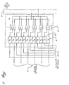
- Figure 1 depicts a basic Power Line Coupler Modem (PLCM) 10 which consists of at least two Power Line Couplers (C1 - Cn) 18 plus an equal number of modulators (M1 - Mn) 16 and demodulators (D1 - Dn) 20. Data, usually in the form of a digital bit stream, comes from a device capable of sending parallel digital data (not shown), such as a personal computer or microprocessor based device. It should be noted that the data could be analog information such as voice, video, stereo, or other analog signals.
- Data enters the
PLCM 10 via theparallel inputs 14. The data is modulated to a preselected modulation frequency by its associated modulator (M1 - Mn) 16. After each data stream is modulated at the modulators it is passed to its associated coupler (C1 - Cn) or Power Line Carrier (PLC) 18. Eachcoupler 18 is phase linear and resistively matched at or around the modulation (carrier) frequency to the characteristic impedance of theAC power line 12 to which it is connected. Each coupler (C1 - Cn) 18 is connected to one another resulting in an addition of all the modulated data streams as they are connected to the conventional wiring orAC power line 12. - A second PLCM, shown in Figure 1, is identical to the
first PLCM 10. The addition of all the modulated data streams enters thesecond PLCM 10 from theAC power line 12. The couplers of Figure 8 (C1 - Cn) 18 are impedance matched to theAC power line 12 and phase linear at the preselected filter frequencies. Each coupler filters the incoming signal and extracts a single preselected modulated data stream. The modulated data stream is sent from the couplers (C1 - Cn) 18 to an associated demodulator (D1 - Dn) 16. Eachdemodulator 16 removes the modulating carrier signal from the data leaving the data which was sent by the first PLCM. This data is placed onto its associated parallel output lines. The output lines carry the data to an electronic device capable of receiving parallel digital data such as a computer, printer, or other electronic device. - This entire communication process can be repeated in the opposite direction. That is, the second PLCM can send data to the first PLCM via the
AC power line 12. The generic data rate at which theparallel input 14 andoutput 22 lines are capable of operating at is in the range of 50 to 100 KSymbols/sec for each line. The PLCM can be configured to handle any size parallel bus and the signals on the bus can be anything from DC voltage levels to binary signals to multiple analog signals. - The maximum communication distance is calculated from the raw speed of each digital bit stream. Dividing the speed of an electron, 300,000 km/sec, by the speed of the bit stream, 100 KSymbols/sec, we get 3 km/bit. Normally only a fraction of the 300,000 km/sec can be assumed for electron speed, thus the maximum communication distance will be closer to 2 km.
- Figure 2 depicts the
basic PLCM 10 wherein theparallel inputs 14 are connected to ademultiplexer 26 and the parallel outputs are connected to amultiplexer 28. In this configuration thePLCM 10 can receive serial or parallel (herein "data stream) data stream on theinput line 24 from a device capable of sending a data stream (not shown). Thedemultiplexer 26 receives the data stream and converts it to parallel data for the parallel input lines. The PLCM then operates as described above. In short, each signal on the parallel input line is modulated, then coupled to the AC power line. The signal is then received by a second PLCM wherein the modulated signals are coupled to the PLCM, separated, filtered, demodulated and sent out on the parallel output lines 22. - The
parallel output lines 22 are connected to a multiplexer which converts the parallel data back to its original data stream. This data stream can be received by an electronic device designed to receive serial or parallel data. - For example, referring to Figure 7, PC1, a personal computer, may have a data stream port through which it sends and receives data. PC1 may send data to PC2 through the AC power line by first sending the data stream to a first PLCM which connects the data in a modulated format onto the AC power line. A second PLCM then can receive the modulated data, change it back into its original data stream form and connect it PC2 which, in turn, receives the data. Each transmission is addressable to preselect the destination.
- Since the basic PLCM configuration is capable of handling a symbol rate of 80 KSymbols/sec per each input or output parallel line, the addition of another parallel line acts as a data speed multiplier increasing the baud rate and overall throughput of the PLCM. For example, if two modulators and demodulators are used in each PLCM the overall throughput of the PLCM is 80 KSymbols/
sec X 2 = 160 KSymbols/sec. If eight modulators and demodulators are used in the PLCM the overall throughput of the PLCM is 80 KSymbols/secparallel line X 4 parallel lines = 320 Kbaud. - Quadrature phase shift keying modulation techniques are illustrated in Figure 3. As explained herein, quadrature phase shifting can be used successfully in the novel PLCM to double the baud rate of each input or output parallel line in the PLCM.
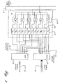
- Figure 3 depicts a phase shifting PLCM 10a with
parallel input lines 14 which carry digital data into the quadrature phase shift keying (QPSK)modulator 34. The QPSK modulator assigns a 90, 180, 270 or 360 degree phase shift for each two bits of data and shifts the modulation frequency accordingly. For example, data bits "00" are assigned a 90 degree phase shift, "01" are assigned 180, "10" are assigned 270 degrees and "11" assigned a 360 degree shift. This technique essentially packs the data in a 2:1 ratio. Thus, the speed of each parallel input line is increased by a factor of two over the general modulation technique described in the basic PLCM. - The shifted modulation signal is coupled to the
AC power line 12 by thePLCs 18. As with the basic PLCM all parallel shifted modulation signals are added together into a conglomerate modulation signal and sent over the AC power line to a second PLCM 10a. The second PLCM 10a (not shown) located at another point on theAC power line 12 receives the conglomerate modulation signal and separates and filters each distinct signal at thecouplers 18. - Since the
PLCs 18 are phase linear due to the use of air-core transformers and impedance matched to the AC power line at the modulation frequency, the encoded phase shifts are undisturbed when passing through them. Each shifted modulation signal proceeds to the phase lock loop (PLL)circuit 36. ThePLL 36 assures the specific predetermined frequency and bandwidth are locked onto and do not drift prior to insertion into theQPSK demodulator 34. A possible bandwidth for the PLL is 50 KHz. Other frequency locking circuits can be used here as well. - At the QPSK demodulator the phase shifts in the modulated signals are demodulated (decoded) back into their original digital form. A 90 degree phase shift is demodulated into a "00" a 180 degree phase shift to a "01", and so forth. The data stream is then sent out on the associated parallel output data line.
- Figure 4, similar to Figure 2, depicts how multiplexer and demultiplexer circuits can increase the baud rate of the phase shifting PLCM 10a to that of a high speed data stream input or output line. The multiplexer receives input data on the data stream input line then converts the data to multiplexed parallel data and connects the data to the parallel input lines. The data rate on each input parallel line is equal to the speed of the input data stream divided by the total number of parallel input lines. The more parallel input data lines the greater the speed of the data stream input lines that can be catered to by the PLCM. Using QPSK modulation each parallel input and output parallel data line operates at baud rates of about 160 kbaud. Therefore, if eight input and output data lines are used the overall throughput of the PLCM using quadrature phase shift keying is 160 Kbaud multiplied by four, totaling 640 Kbaud. The use of more than eight input and output data lines can increase the baud rate dramatically.
- If an eight state phase shift modulator (octaphase shift key modulator) (OPSKM) is used instead of a quadrature phase shift modulator (four state modulator) then every three bits of data are assigned to each forty-five degree shift in phase. For example, "000" is assigned a 45 degree phase shift, "001" is assigned a 90 degree phase shift, "010" is assigned 135 degrees, "011" gets 180 degrees, "100 gets 225, "101" gets 270, "110" gets 315, and "111" gets a 360 degree phase shift assigned to it. This technique packs the data in a 3:1 ratio. Thus, the speed of each parallel input line is increased by a factor of 3 over the general input line. Using OPSK modulation and eight parallel input lines, each input line through put will be approximately 80 KSymbols/
sec x 4 equaling 320 KSymbols/sec. Multiplying by eight lines the total throughput of a PLCM using OPSK modulation is about 2.5 MSymbols/sec. - The
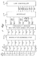
demultiplexer circuitry 26 operates the same way as described for figure 2. Theparallel output lines 22, in figure 4, carry the digital data from the QPSK modulators 34 to the multiplexer where it is multiplexed from parallel to data stream data and sent out on the datascreen output line 30. - For example, a Digital Signal Processing (DSP) chip can be used, using the ATT DSP 32C in which the digital bandpass filter, the PLL and the OPSK MOD/DEMOD can be programmed. The Carrier Sense Multiple Access/Collision Detection will be handled in the PLC modem. Logical separation of LAN traffic (addressability) may be used as well as the Forward Error Correction (FEC) and Data Compression, all of which are controlled by the CPU.
- Obviously, the best carrier frequencies which can be chosen between the main harmonics of the 60 Hz, are every 30 KHz in the spectrum. In that case, the 1:1 received inband noise (threshold) is only around 5-15 mV peak to peak. Thus, ten channels can be used at the following carrier frequencies: F1=165 KHz, F2=195 KHz, F3=225 KHz, F4=255 KHz, F5=285 KHz, F6=315 KHz, F7=345 KHz, F8=375 KHz, F9=405 KHz, F10=435 KHz using about 20-24 KHz bandwidth for each channel and OPSK. Similarly, about 33.33 KSymbols/sec per channels and 1Mbaud final speed can be reached. The usage of more channels will bring up the price of the modem and since the strong 60Hz harmonics are only every 60 KHz in the spectrum, therefore only four channels are recommended at the following carrier frequencies, while the noise threshold remains about the same as above: F1=210KHz, F2=270 KHz, F3=330 KHz, F4=390 KHz, using about 50-54KHz bandwidth for each channels and OPSK. Similarly, about 83.33 KSymbols/sec per channels and 1 Mbaud final speed can be reached. It is also possible to add a fifth channel at 150KHz. In Europe, the Power Line carrier frequency rules are different. They do not allow higher than 100KHz frequency transmission, therefore four channels are recommended at the following carrier frequencies: F1=56KHz, F2=69KHz, F3=82KHz, F4=95KHz using about 9KHz bandwidth for each channel and OPSK. The maximum final speed can be about 200Kbaud. Since they have 50Hz power, the strong harmonics appear at every 25KHz in the spectrum, and the threshold is around 15-40mV peak to peak.
- Figure 5 and Figure 6 depict examples of how the PLCM and modulator/demodulator circuits can be used in coexistence with network controllers used in a Local Area Network (LAN) system, (Figure 5), or other networking system, (Figure 6). This is an inexpensive technique for creating or expanding a LAN or Ethernet System because no additional wiring must be added to interconnect the system. Other network controllers such as Starlan, Token Ring, etc. can also be used. Also, the use of various types of network software, such as Novell, can be implemented.
- Power Line Couplers (PLC's), as described in my co-pending application serial number 822,326 filed Jan. 17, 1992, are part of the present invention's embodiment because of their linear phase shifting qualities. PLC's allow signal information to be placed on conventional electrical wiring and retrieved, noise free, at another position. PLC's allow communication over existing electrical power AC wiring found in buildings. PLC's also allow for communication over long distance through power lines outside buildings. Such a configuration on outside wiring will allow efficient data communication from building to building without the installation of new cabling. With a PLCM, which incorporates a PLC, existing electrical wiring in any form can become a means for transmitting and receiving communications at rates of speed that can exceed 1 Mbaud.
- Figure 7 depicts a possible configuration for data communication between multiple microprocessor based and electrical/electronic equipment. Any personal computer (PC), printer, or other device can be connected to a
PLCM 10, 10a. The PLCM, plugged into a standard wall socket, will allow the device to transmit and/or receive communication information over the electrical wiring of thebuilding 12. - Note that if multiple phases are present (phase A, B, & C) and devices which must communicate via a PLCM are connected to separate phases, then a simple circuit 70 can be used to link the phases together.
- While particular embodiments of the present invention are disclosed herein, it is not intended to limit the invention to such disclosure, and changes and modifications may be incorporated and embodied within the scope of the following claims.
Claims (37)
- Communication transmitting apparatus (10) for transmitting multiple modulated information signals over an electric power line (12) comprising:characterized by further comprising:a transmitting station (10) adapted to be connected to said electrical line said transmitting station being arranged to conduct to said electrical line (12) said multiple modulated information signals,(a) a plurality of transmitting station input data lines (14,26,28) arranged to carry first electrical information signals,(b) a plurality of transmitting station modulators (16), each one associated with one of said transmitting station input data lines and operating at a different preselected modulation frequency arranged to modulate said first electrical information signals received from said associated transmitting station input data lines to develop ones of said multiple modulated information signals, and(c) a plurality of phase-shift linear first station dielectric-core couplers (C1, C2... Cn) impedance matched at the modulation frequency with said electrical line said couplers being arranged to couple said ones of said multiple modulated information signals developed by said transmitting station modulators to said electrical line.
- Communication receiving apparatus (10) for receiving multiple modulated information signals over an electric power line (12) comprising:characterized by further comprising:a receiving station (10) connected to said electrical line and arranged to receive from said electrical line (10) said multiple modulated information signals,(a) plurality of receiving station demodulators (D1, D2, ... Dn), each one operating at a different preselectred demodulation frequency arranged to demodulate components of said multiple modulated information signals received from said electrical line,(b) a plurality of receiving station output data lines (22), each one associated with one of said receiving station demodulators arranged to carry electrical information signals, and(c) a plurality of phase-shift linear first station dielectric-core couplers (C1, C2 ... Cn) impedence matched with said electrical line at the component modulation frequency said couplers being arranged to:(i) separate said components of said multiple modulated information signals without substantially affecting the phase of said components of said multiple modulated information signals, and(ii) pass said components of said multiple modulated information signals in parallel to said receiving station demodualtors (D1 D2, ... Dn).
- Communication apparatus in accordance with Claim 1 further comprising a receiving station (10) arranged to receive said multiple modulated signals.
- Communication apparatus in accordance with Claim 3 wherein said receiving station 10) comprises air-core couplers (C1, C2 ... Cn) impedance matched to said electrical line.
- Communication apparatus in accordance with Claim 2 further comprising a transmitting station (10) arranged to transmit said multiple modulated signal.
- Communication apparatus in accordance with Claim 5 wherein said transmitting station comprises air-core couplers C1, C2 ... Cn) impedance matched to said electrical line.
- The communication apparatus of Claim 5 wherein said couplers comprise air-core couplers impedance matched to said electrical line.
- A communication transmitting apparatus (10) in accordance with Claim 1 wherein all said input data lines are connected to a demultiplexer which demultiplexes the electrical information on an input data stream line (24) into said input data lines.
- A communication receiving apparatus (10) in accordance with Claim 2 wherein a multiplexer receives output data from the data lines and multiplexes the data into data stream output data and sends the output data on to a serial output line.
- A communication receiving apparatus (10) in accordance with Claim 2 wherein each demodulator incorporates phase-lock-loop circuitry prior to demodulation.
- Communication transmitting apparatus in accordance with Claim 1 wherein the transmitting station data input lines are arranged to receive computer network information signals from at least one of a LAN, an Ethernet system, a Starlan system and a Token Ring system.
- Communication transmitting apparatus according to Claim 1 or 11 wherein said modulators are arranged to modulate by one of quadrature phase shift key modulation and octaphase phase shift key modulation.
- Communication receiving apparatus in accordance with Claim 2 wherein the receiving station data output lines are arranged to output computer network information signals to at least one of a LAN, an Ethernet system, a Starlan system and a Token Ring system.
- Communication receiving apparatus in accordance with Claim 2 or 13 wherein the said demodulators are arranged to demodulate by one of quadrature phase shift key demodulation and octaphase phase shift key demodulation.
- A communication transceiver apparatus for an Ethernet network (54) system for transmitting and receiving first and second multiple modulated information signals via an electric power line (12), the improvement comprising:a transceiver station (26, 28; 16, 20; 18) connected to said electric power line arranged to:(a) produce said first multiple modulated information signals,(b) conduct to said electric power line (12) first multiple modulated information signals,(c) receive from said electric power line (12) second multiple modulated information signals, and(d) process second modulated information signals:said transceiver station including:(i) a plurality of input data line carrying first electric information signals;(ii) a plurality of parallel connected modulators (16), each one associated with one of said input data lines and operating at a different preselected modulation frequency, arranged to modulate said first electrical information signals received from associated input data lines to develop components of said first multiple modulated information signals,(iii) a plurality of parallel connected demodulators (20), each one operating at a different preselected demodulation frequency, arranged to demodulate components of said multiple modulated information signals received from said electric power line;(iv) a plurality of output data lines, each one associated with one of said demodulators arranged to carry second electrical information signals;and a plurality of parallel connected couplers arranged to:(a) couple said components of said first multiple modulated information signals developed by said transceiver station modulators to the electric power line;(b) separate said components of said second multiple modulated information signals, and(c) pass said components of said second multiple modulated information signals in parallel to said demodulators.
- A communication transceiver apparatus according to Claim 15 in which said coupler comprises:a plurality of phase-shift linear dielectric-core couplers (18) impedance matched with said electrical line at the modulation frequency which separate components of said second multiple modulated information signals.
- A communication apparatus which transmits and receives multiple modulated signals over an electrical line which comprises:a first station and a second station;said first station capable of receiving high speed data and. converting the high speed data into multiple modulated signals for sending simultaneously over the electrical line to said second station, said second station being capable of simultaneously demodulating the multiple modulated signals and converting the signals back into high speed data; andeach said station incorporating dielectric core couplers for coupling the multiple modulated signals between the electrical line and each station.
- A communication apparatus in accordance with claim 17 wherein the dielectric-core couplers couple the multiple modulated signals between the electrical line and each station in a phase linear manner.
- A communication apparatus in accordance with claim 17 wherein the electrical line is any conventional wiring.
- A communication apparatus in accordance with claim 17 wherein the multiple modulated signal sent over the electrical line can be sent for a distance of 3km.
- A communication apparatus in accordance with claim 17 wherein the multiple modulating signal is a combination of multiplexed digital data which is modulated at different distinct preselected frequencies and then combined.
- A communication apparatus in accordance with claim 17 wherein the high speed data is serial data traveling at a rate of up to 100 KSymbols/sec.
- A communication apparatus in accordance with claim 17 wherein each station utilizes quadrature phase shift keying techniques when modulating and demodulating the multiple modulated signals.
- A communication apparatus in accordance with claim 22 wherein the high speed data is serial data traveling at a rate of at least 160 kbits/sec.
- A communication apparatus in accordance with claim 17 wherein each station utilizes octaphase shift keying techniques.
- A communication apparatus in accordance with claim 23 wherein the data error rate of the communication apparatus is less than 10-9.
- A communication apparatus which transmits and receives composite modulated signals over an electrical line at high speeds comprising:a first station and second station connected to each other by an electrical line;each station including multiple input and output data lines, modulators, demodulators and air-core couplers;multiple output data lines carry electrical information to modulators, one data line to each modulator;said modulators, each operating at a different preselected modulation frequency, modulate output data received from a corresponding output data line and pass such modulated data signal to an air-core coupler;each air-core coupler, which is phase-shift linear and impedance matched with the electrical line at the preselected modulation frequency, couples each modulated output data signal to the electrical line by creating and output composite signal;each air-core coupler also receives an input composite from the electrical line and separates the input composite signal into parallel input modulation signals, without effecting the phase of the parallel input modulation signals, and passes said input modulation signals to the demodulators;each demodulator, one for each input modulator signal, demodulates the input modulation signal and transmits it on an input data line as input data.
- A communication apparatus in accordance with Claim 27 wherein all input data lines are connected to a multiplexer which multiplexes the electrical information on the input data lines into an input data stream line and
all input data lines are connected to a demultiplexer which demultiplexes the electrical information on the output data stream line onto the output data lines. - A communication apparatus in accordance with Claim 28 wherein the input and output data stream lines operate individually at approximately 80 KSymbols/sec multiplied by the number of input or output data lines.
- A communication apparatus in accordance with Claim 27 wherein the air-core couplers have a dielectric core.
- A communication apparatus in accordance with Claim 27 wherein the electrical information on the input and output data lines is analog information.
- A communication apparatus in accordance with claim 28 wherein demodulators incorporate phase-lock-loop circuitry prior to demodulation.
- A communication apparatus in accordance with claim 28 wherein modulators and demodulators incorporate Quadrature Phase Shift Keying Circuitry.
- A communication apparatus in accordance with claim 28 wherein modulators and demodulators incorporate octaphase shift keying circuitry.
- A communication apparatus in accordance with claim 27 wherein each station includes a multiplexer, demultiplexer, serial input line and serial output line;
each data stream output line carries output data to a multiplexer;
said multiplexer multiplexes the data stream output data onto the multiple output data lines;
each demultiplexer receives input data from the input data lines and demultiplexes the data into data stream input data and sends the input data on the data stream input line. - A communication apparatus in accordance with claim 33 wherein both the data stream input and data stream output line travel at data speeds exceeding approximately 1 Mbaud.
- A method of communication which allows multiple electronic processors to communicate on an electrical line comprising:providing a first encoder/decoder connected to a first electronic processor and at least a second encoder/decoder unit connected to a second electronic processor, both first and second encoder/decoder units being connected to an electrical line and utilizing air-core couplers;receiving a first data stream from the first electronic processor;multiplexing the first data stream into multiple parallel data streams;modulating each parallel data stream at a different distinct preselected modulation frequency resulting in multiple modulated data streams;combining the multiple modulated data streams into a combination data stream;sending the combination data stream on the electrical line in a phase linear manner;receiving the combination data stream at the second encoder/decoder unit;separating the combination data stream, in a phase linear manner, into multiple modulated data streams each modulating at a different distinct modulation frequency;demodulating each modulated data stream and creating parallel data streams;demultiplexing the parallel data streams into a single second data stream;connecting second data stream to the second electronic processor.
Applications Claiming Priority (3)
| Application Number | Priority Date | Filing Date | Title |
|---|---|---|---|
| US884123 | 1992-05-18 | ||
| US07/884,123 US5351272A (en) | 1992-05-18 | 1992-05-18 | Communications apparatus and method for transmitting and receiving multiple modulated signals over electrical lines |
| EP93913976A EP0689738A4 (en) | 1992-05-18 | 1993-05-18 | Power line coupler modem device for communication over electrical lines |
Related Parent Applications (1)
| Application Number | Title | Priority Date | Filing Date |
|---|---|---|---|
| EP93913976A Division EP0689738A4 (en) | 1992-05-18 | 1993-05-18 | Power line coupler modem device for communication over electrical lines |
Publications (1)
| Publication Number | Publication Date |
|---|---|
| EP1416645A2 true EP1416645A2 (en) | 2004-05-06 |
Family
ID=25384005
Family Applications (3)
| Application Number | Title | Priority Date | Filing Date |
|---|---|---|---|
| EP06013222A Ceased EP1777832A1 (en) | 1992-05-18 | 1993-05-18 | Power line coupler modem device for communication over electrical lines |
| EP93913976A Ceased EP0689738A4 (en) | 1992-05-18 | 1993-05-18 | Power line coupler modem device for communication over electrical lines |
| EP20040000976 Withdrawn EP1416645A2 (en) | 1992-05-18 | 1993-05-18 | Power line coupler modem device for communication over electrical lines |
Family Applications Before (2)
| Application Number | Title | Priority Date | Filing Date |
|---|---|---|---|
| EP06013222A Ceased EP1777832A1 (en) | 1992-05-18 | 1993-05-18 | Power line coupler modem device for communication over electrical lines |
| EP93913976A Ceased EP0689738A4 (en) | 1992-05-18 | 1993-05-18 | Power line coupler modem device for communication over electrical lines |
Country Status (5)
| Country | Link |
|---|---|
| US (1) | US5351272A (en) |
| EP (3) | EP1777832A1 (en) |
| JP (1) | JP3411278B2 (en) |
| CA (1) | CA2135918C (en) |
| WO (1) | WO1993023928A1 (en) |
Cited By (1)
| Publication number | Priority date | Publication date | Assignee | Title |
|---|---|---|---|---|
| EP2506445A1 (en) * | 2011-03-31 | 2012-10-03 | ABB Technology AG | Connection device, system and method for transmitting signals between a control centre and at least one field device in an industrial assembly |
Families Citing this family (272)
| Publication number | Priority date | Publication date | Assignee | Title |
|---|---|---|---|---|
| US6452482B1 (en) | 1999-12-30 | 2002-09-17 | Ambient Corporation | Inductive coupling of a data signal to a power transmission cable |
| US6104707A (en) * | 1989-04-28 | 2000-08-15 | Videocom, Inc. | Transformer coupler for communication over various lines |
| US5625863A (en) * | 1989-04-28 | 1997-04-29 | Videocom, Inc. | Video distribution system using in-wall wiring |
| US5592482A (en) * | 1989-04-28 | 1997-01-07 | Abraham; Charles | Video distribution system using in-wall wiring |
| US6014386A (en) * | 1989-10-30 | 2000-01-11 | Videocom, Inc. | System and method for high speed communication of video, voice and error-free data over in-wall wiring |
| FR2696055B1 (en) * | 1992-09-23 | 1994-12-09 | Sgs Thomson Microelectronics | Smart electrical outlet. |
| GB9222205D0 (en) * | 1992-10-22 | 1992-12-02 | Norweb Plc | Low voltage filter |
| US6144292A (en) * | 1992-10-22 | 2000-11-07 | Norweb Plc | Powerline communications network employing TDMA, FDMA and/or CDMA |
| US6282405B1 (en) | 1992-10-22 | 2001-08-28 | Norweb Plc | Hybrid electricity and telecommunications distribution network |
| GB9407934D0 (en) * | 1994-04-21 | 1994-06-15 | Norweb Plc | Transmission network and filter therefor |
| US5530737A (en) | 1993-03-22 | 1996-06-25 | Phonex Corporation | Secure access telephone extension system and method |
| KR0128169B1 (en) * | 1993-12-31 | 1998-04-15 | 김광호 | Home automation |
| FR2720576B1 (en) * | 1994-05-24 | 1996-06-21 | Sgs Thomson Microelectronics | Compatible interface for the installation of industrial and professional household appliances. |
| US5497397A (en) * | 1994-06-29 | 1996-03-05 | General Electric Company | Parallel dataword modulation scheme |
| US5835005A (en) * | 1994-07-13 | 1998-11-10 | Omron Corporation | Power-line data transmission method and system utilizing relay stations |
| GB9417359D0 (en) * | 1994-08-26 | 1994-10-19 | Norweb Plc | A power transmission network and filter therefor |
| US5818821A (en) | 1994-12-30 | 1998-10-06 | Intelogis, Inc. | Universal lan power line carrier repeater system and method |
| US5614811A (en) * | 1995-09-26 | 1997-03-25 | Dyalem Concepts, Inc. | Power line control system |
| WO1997023057A1 (en) * | 1995-12-19 | 1997-06-26 | Elcom Technologies Corporation | Power line communications system with selective program reception |
| WO1997023079A1 (en) * | 1995-12-20 | 1997-06-26 | B.J. MCCORMICK TRUST doing business as J.V.M. INDUSTRIES, INC. | Split harmonic frequency modulation data transmission system |
| US5844949A (en) * | 1996-10-09 | 1998-12-01 | General Electric Company | Power line communication system |
| DE19716011A1 (en) * | 1997-04-17 | 1998-10-22 | Abb Research Ltd | Method and device for transmitting information via power supply lines |
| US6151480A (en) * | 1997-06-27 | 2000-11-21 | Adc Telecommunications, Inc. | System and method for distributing RF signals over power lines within a substantially closed environment |
| US5970127A (en) | 1997-10-16 | 1999-10-19 | Phonex Corporation | Caller identification system for wireless phone jacks and wireless modem jacks |
| US6055435A (en) | 1997-10-16 | 2000-04-25 | Phonex Corporation | Wireless telephone connection surge suppressor |
| US6107912A (en) | 1997-12-08 | 2000-08-22 | Phonex Corporation | Wireless modem jack |
| US6188986B1 (en) * | 1998-01-02 | 2001-02-13 | Vos Systems, Inc. | Voice activated switch method and apparatus |
| JPH11234180A (en) * | 1998-02-13 | 1999-08-27 | Sony Corp | Electric lamp power-line carrier communication system and its equipment |
| WO1999053627A1 (en) | 1998-04-10 | 1999-10-21 | Chrimar Systems, Inc. Doing Business As Cms Technologies | System for communicating with electronic equipment on a network |
| US6480510B1 (en) | 1998-07-28 | 2002-11-12 | Serconet Ltd. | Local area network of serial intelligent cells |
| US6246868B1 (en) | 1998-08-14 | 2001-06-12 | Phonex Corporation | Conversion and distribution of incoming wireless telephone signals using the power line |
| US6243571B1 (en) | 1998-09-21 | 2001-06-05 | Phonex Corporation | Method and system for distribution of wireless signals for increased wireless coverage using power lines |
| WO2000038402A1 (en) * | 1998-12-23 | 2000-06-29 | Enikia Llc | Power line communication system for local area networks |
| US6473608B1 (en) | 1999-01-12 | 2002-10-29 | Powerdsine Ltd. | Structure cabling system |
| US7046983B2 (en) * | 1999-08-02 | 2006-05-16 | Powerdsine, Ltd. | Integral board and module for power over LAN |
| US7346785B2 (en) * | 1999-01-12 | 2008-03-18 | Microsemi Corp. - Analog Mixed Signal Group Ltd. | Structure cabling system |
| US6643566B1 (en) * | 1999-01-12 | 2003-11-04 | Powerdsine Ltd. | System for power delivery over data communication cabling infrastructure |
| US6195004B1 (en) | 1999-05-14 | 2001-02-27 | Lucent Technologies, Inc. | Distributed earcon local area network |
| US6956826B1 (en) | 1999-07-07 | 2005-10-18 | Serconet Ltd. | Local area network for distributing data communication, sensing and control signals |
| US6690677B1 (en) | 1999-07-20 | 2004-02-10 | Serconet Ltd. | Network for telephony and data communication |
| US6594630B1 (en) | 1999-11-19 | 2003-07-15 | Voice Signal Technologies, Inc. | Voice-activated control for electrical device |
| US7154382B2 (en) * | 1999-12-30 | 2006-12-26 | Ambient Corporation | Arrangement of inductive couplers for data communication |
| WO2001056182A1 (en) * | 2000-01-31 | 2001-08-02 | Texas Instruments Incorporated | Home networking over phone lines |
| US6668058B2 (en) | 2000-03-07 | 2003-12-23 | Telkonet Communications, Inc. | Power line telephony exchange |
| US6496104B2 (en) | 2000-03-15 | 2002-12-17 | Current Technologies, L.L.C. | System and method for communication via power lines using ultra-short pulses |
| US6549616B1 (en) | 2000-03-20 | 2003-04-15 | Serconet Ltd. | Telephone outlet for implementing a local area network over telephone lines and a local area network using such outlets |
| US6998962B2 (en) | 2000-04-14 | 2006-02-14 | Current Technologies, Llc | Power line communication apparatus and method of using the same |
| US6842459B1 (en) | 2000-04-19 | 2005-01-11 | Serconet Ltd. | Network combining wired and non-wired segments |
| US6812970B1 (en) | 2000-05-15 | 2004-11-02 | Mcbride Richard L. | Video camera utilizing power line modulation |
| US6686832B2 (en) * | 2000-05-23 | 2004-02-03 | Satius, Inc. | High frequency network multiplexed communications over various lines |
| US6922135B2 (en) | 2000-05-23 | 2005-07-26 | Satius, Inc. | High frequency network multiplexed communications over various lines using multiple modulated carrier frequencies |
| US6396392B1 (en) * | 2000-05-23 | 2002-05-28 | Wire21, Inc. | High frequency network communications over various lines |
| US20020067772A1 (en) * | 2000-06-28 | 2002-06-06 | Shepperd Michael B. | Method and system for sending information over metal wire |
| US6711385B1 (en) | 2000-07-06 | 2004-03-23 | Satius, Inc. | Coupler for wireless communications |
| US7248148B2 (en) * | 2000-08-09 | 2007-07-24 | Current Technologies, Llc | Power line coupling device and method of using the same |
| US7245201B1 (en) | 2000-08-09 | 2007-07-17 | Current Technologies, Llc | Power line coupling device and method of using the same |
| US7283554B2 (en) * | 2001-02-12 | 2007-10-16 | Texas Instruments Incorporated | Network manager for a hybrid network environment |
| EP1371219A4 (en) * | 2001-02-14 | 2006-06-21 | Current Tech Llc | Data communication over a power line |
| EP1374436A1 (en) | 2001-03-29 | 2004-01-02 | Ambient Corporation | Coupling circuit for power line communications |
| KR20020087543A (en) * | 2001-05-14 | 2002-11-23 | 엘지전자 주식회사 | Packet structure for power line communication |
| US7245472B2 (en) * | 2001-05-18 | 2007-07-17 | Curretn Grid, Llc | Medium voltage signal coupling structure for last leg power grid high-speed data network |
| WO2003001783A1 (en) * | 2001-06-22 | 2003-01-03 | Power-Linx, Inc. | Hotel computer networking system |
| US6975212B2 (en) * | 2001-10-02 | 2005-12-13 | Telkonet Communications, Inc. | Method and apparatus for attaching power line communications to customer premises |
| US7091831B2 (en) * | 2001-10-02 | 2006-08-15 | Telkonet Communications, Inc. | Method and apparatus for attaching power line communications to customer premises |
| JP3744435B2 (en) * | 2002-02-13 | 2006-02-08 | 住友電気工業株式会社 | Power line carrier communication modem |
| US7199699B1 (en) | 2002-02-19 | 2007-04-03 | Current Technologies, Llc | Facilitating communication with power line communication devices |
| US7076378B1 (en) | 2002-11-13 | 2006-07-11 | Current Technologies, Llc | Device and method for providing power line characteristics and diagnostics |
| IL154234A (en) | 2003-01-30 | 2010-12-30 | Mosaid Technologies Inc | Method and system for providing dc power on local telephone lines |
| IL154921A (en) | 2003-03-13 | 2011-02-28 | Mosaid Technologies Inc | Telephone system having multiple distinct sources and accessories therefor |
| US20040233928A1 (en) * | 2003-05-07 | 2004-11-25 | Telkonet, Inc. | Network topology and packet routing method using low voltage power wiring |
| US20040227623A1 (en) * | 2003-05-07 | 2004-11-18 | Telkonet, Inc. | Network topology and packet routing method using low voltage power wiring |
| US7308103B2 (en) | 2003-05-08 | 2007-12-11 | Current Technologies, Llc | Power line communication device and method of using the same |
| US6995658B2 (en) * | 2003-06-11 | 2006-02-07 | The Boeing Company | Digital communication over 28VDC power line |
| US7460467B1 (en) | 2003-07-23 | 2008-12-02 | Current Technologies, Llc | Voice-over-IP network test device and method |
| IL159838A0 (en) | 2004-01-13 | 2004-06-20 | Yehuda Binder | Information device |
| US11152971B2 (en) * | 2004-02-02 | 2021-10-19 | Charles Abraham | Frequency modulated OFDM over various communication media |
| US7113134B1 (en) | 2004-03-12 | 2006-09-26 | Current Technologies, Llc | Transformer antenna device and method of using the same |
| US20060017324A1 (en) * | 2004-07-21 | 2006-01-26 | Advanced Powerline Technologies, Inc. | Communications network using installed electrical power lines |
| EP1628412A1 (en) * | 2004-08-18 | 2006-02-22 | X'Max Corp. | Method and device for transmitting non-broadband signals using power lines as media |
| US7391317B2 (en) * | 2004-09-08 | 2008-06-24 | Satius, Inc. | Apparatus and method for transmitting digital data over various communication media |
| US7170367B2 (en) * | 2004-10-25 | 2007-01-30 | Ambient Corporation | Inductive coupler for power line communications |
| WO2006075767A2 (en) * | 2005-01-13 | 2006-07-20 | Matsushita Electric Industrial Co., Ltd. | Various data transmission systems and data transmission methods for transporting vehicles |
| US7199706B2 (en) * | 2005-02-22 | 2007-04-03 | Sony Corporation | PLC intercom/monitor |
| US20060193313A1 (en) * | 2005-02-25 | 2006-08-31 | Telkonet, Inc. | Local area network above telephony infrastructure |
| US20060193310A1 (en) * | 2005-02-25 | 2006-08-31 | Telkonet, Inc. | Local area network above telephony methods and devices |
| US20060193336A1 (en) * | 2005-02-25 | 2006-08-31 | Telkonet, Inc. | Local area network above cable television methods and devices |
| US7804763B2 (en) * | 2005-04-04 | 2010-09-28 | Current Technologies, Llc | Power line communication device and method |
| US7307512B2 (en) * | 2005-04-29 | 2007-12-11 | Current Technologies, Llc | Power line coupling device and method of use |
| TWM285855U (en) * | 2005-05-03 | 2006-01-11 | Hansder Technology Co Ltd | Door intercom communication system and method of using same |
| US7319717B2 (en) * | 2005-06-28 | 2008-01-15 | International Broadband Electric Communications, Inc. | Device and method for enabling communications signals using a medium voltage power line |
| US7414526B2 (en) * | 2005-06-28 | 2008-08-19 | International Broadband Communications, Inc. | Coupling of communications signals to a power line |
| US7778514B2 (en) * | 2005-07-15 | 2010-08-17 | International Broadband Electric Communications, Inc. | Coupling of communications signals to a power line |
| US7522812B2 (en) * | 2005-07-15 | 2009-04-21 | International Broadband Electric Communications, Inc. | Coupling of communications signals to a power line |
| US7667344B2 (en) * | 2005-07-15 | 2010-02-23 | International Broadband Electric Communications, Inc. | Coupling communications signals to underground power lines |
| US20070273205A1 (en) * | 2006-05-22 | 2007-11-29 | Denso Corporation | Communication system for use in data communications between power generator and external unit |
| US20080056338A1 (en) * | 2006-08-28 | 2008-03-06 | David Stanley Yaney | Power Line Communication Device and Method with Frequency Shifted Modem |
| US7895456B2 (en) * | 2006-11-12 | 2011-02-22 | Microsemi Corp. - Analog Mixed Signal Group Ltd | Reduced guard band for power over Ethernet |
| US7876174B2 (en) | 2007-06-26 | 2011-01-25 | Current Technologies, Llc | Power line coupling device and method |
| US7795994B2 (en) * | 2007-06-26 | 2010-09-14 | Current Technologies, Llc | Power line coupling device and method |
| US20090085726A1 (en) * | 2007-09-27 | 2009-04-02 | Radtke William O | Power Line Communications Coupling Device and Method |
| US8160753B2 (en) * | 2008-07-31 | 2012-04-17 | Microsemi Corp.—Analog Mixed Signal Group Ltd. | Time integrated guard band |
| US8195965B2 (en) * | 2008-11-04 | 2012-06-05 | Microsemi Corp. - Analog Mixed Signal Group Ltd. | Compensation for high powered midspan power sourcing equipment |
| US9113347B2 (en) | 2012-12-05 | 2015-08-18 | At&T Intellectual Property I, Lp | Backhaul link for distributed antenna system |
| US10009065B2 (en) | 2012-12-05 | 2018-06-26 | At&T Intellectual Property I, L.P. | Backhaul link for distributed antenna system |
| US9525524B2 (en) | 2013-05-31 | 2016-12-20 | At&T Intellectual Property I, L.P. | Remote distributed antenna system |
| US9999038B2 (en) | 2013-05-31 | 2018-06-12 | At&T Intellectual Property I, L.P. | Remote distributed antenna system |
| US9688295B2 (en) | 2013-08-23 | 2017-06-27 | Electro-Motive Diesel, Inc. | Trainline network access point for parallel communication |
| US9270335B2 (en) | 2013-08-23 | 2016-02-23 | Electro-Motive Diesel, Inc. | Receive attenuation system for trainline communication networks |
| US9463816B2 (en) | 2013-08-23 | 2016-10-11 | Electro-Motive Diesel, Inc. | Trainline communication network access point including filter |
| US9260123B2 (en) | 2013-08-23 | 2016-02-16 | Electro-Motive Diesel, Inc. | System and method for determining locomotive position in a consist |
| US9073560B2 (en) | 2013-08-23 | 2015-07-07 | Electro-Motive Diesel, Inc. | System and method for determining communication paths in a trainline communication network |
| US8897697B1 (en) | 2013-11-06 | 2014-11-25 | At&T Intellectual Property I, Lp | Millimeter-wave surface-wave communications |
| US9209902B2 (en) | 2013-12-10 | 2015-12-08 | At&T Intellectual Property I, L.P. | Quasi-optical coupler |
| US9560139B2 (en) | 2014-04-11 | 2017-01-31 | Electro-Motive Diesel, Inc. | Train communication network |
| US9744979B2 (en) | 2014-04-11 | 2017-08-29 | Electro-Motive Diesel, Inc. | Train communication network |
| US9692101B2 (en) | 2014-08-26 | 2017-06-27 | At&T Intellectual Property I, L.P. | Guided wave couplers for coupling electromagnetic waves between a waveguide surface and a surface of a wire |
| US9768833B2 (en) | 2014-09-15 | 2017-09-19 | At&T Intellectual Property I, L.P. | Method and apparatus for sensing a condition in a transmission medium of electromagnetic waves |
| US10063280B2 (en) | 2014-09-17 | 2018-08-28 | At&T Intellectual Property I, L.P. | Monitoring and mitigating conditions in a communication network |
| US9628854B2 (en) | 2014-09-29 | 2017-04-18 | At&T Intellectual Property I, L.P. | Method and apparatus for distributing content in a communication network |
| US9615269B2 (en) | 2014-10-02 | 2017-04-04 | At&T Intellectual Property I, L.P. | Method and apparatus that provides fault tolerance in a communication network |
| US9685992B2 (en) | 2014-10-03 | 2017-06-20 | At&T Intellectual Property I, L.P. | Circuit panel network and methods thereof |
| US9503189B2 (en) | 2014-10-10 | 2016-11-22 | At&T Intellectual Property I, L.P. | Method and apparatus for arranging communication sessions in a communication system |
| US9762289B2 (en) | 2014-10-14 | 2017-09-12 | At&T Intellectual Property I, L.P. | Method and apparatus for transmitting or receiving signals in a transportation system |
| US9973299B2 (en) | 2014-10-14 | 2018-05-15 | At&T Intellectual Property I, L.P. | Method and apparatus for adjusting a mode of communication in a communication network |
| US9769020B2 (en) | 2014-10-21 | 2017-09-19 | At&T Intellectual Property I, L.P. | Method and apparatus for responding to events affecting communications in a communication network |
| US9653770B2 (en) | 2014-10-21 | 2017-05-16 | At&T Intellectual Property I, L.P. | Guided wave coupler, coupling module and methods for use therewith |
| US9577306B2 (en) | 2014-10-21 | 2017-02-21 | At&T Intellectual Property I, L.P. | Guided-wave transmission device and methods for use therewith |
| US9312919B1 (en) | 2014-10-21 | 2016-04-12 | At&T Intellectual Property I, Lp | Transmission device with impairment compensation and methods for use therewith |
| US9780834B2 (en) | 2014-10-21 | 2017-10-03 | At&T Intellectual Property I, L.P. | Method and apparatus for transmitting electromagnetic waves |
| US9564947B2 (en) | 2014-10-21 | 2017-02-07 | At&T Intellectual Property I, L.P. | Guided-wave transmission device with diversity and methods for use therewith |
| US9627768B2 (en) | 2014-10-21 | 2017-04-18 | At&T Intellectual Property I, L.P. | Guided-wave transmission device with non-fundamental mode propagation and methods for use therewith |
| US9520945B2 (en) | 2014-10-21 | 2016-12-13 | At&T Intellectual Property I, L.P. | Apparatus for providing communication services and methods thereof |
| US9660689B2 (en) | 2014-11-13 | 2017-05-23 | Honeywell International Inc. | Multiple radio frequency (RF) systems using a common radio frequency port without an RF switch |
| US9654173B2 (en) | 2014-11-20 | 2017-05-16 | At&T Intellectual Property I, L.P. | Apparatus for powering a communication device and methods thereof |
| US9954287B2 (en) | 2014-11-20 | 2018-04-24 | At&T Intellectual Property I, L.P. | Apparatus for converting wireless signals and electromagnetic waves and methods thereof |
| US10009067B2 (en) | 2014-12-04 | 2018-06-26 | At&T Intellectual Property I, L.P. | Method and apparatus for configuring a communication interface |
| US9742462B2 (en) | 2014-12-04 | 2017-08-22 | At&T Intellectual Property I, L.P. | Transmission medium and communication interfaces and methods for use therewith |
| US10243784B2 (en) | 2014-11-20 | 2019-03-26 | At&T Intellectual Property I, L.P. | System for generating topology information and methods thereof |
| US9997819B2 (en) | 2015-06-09 | 2018-06-12 | At&T Intellectual Property I, L.P. | Transmission medium and method for facilitating propagation of electromagnetic waves via a core |
| US9680670B2 (en) | 2014-11-20 | 2017-06-13 | At&T Intellectual Property I, L.P. | Transmission device with channel equalization and control and methods for use therewith |
| US9461706B1 (en) | 2015-07-31 | 2016-10-04 | At&T Intellectual Property I, Lp | Method and apparatus for exchanging communication signals |
| US9544006B2 (en) | 2014-11-20 | 2017-01-10 | At&T Intellectual Property I, L.P. | Transmission device with mode division multiplexing and methods for use therewith |
| US9800327B2 (en) | 2014-11-20 | 2017-10-24 | At&T Intellectual Property I, L.P. | Apparatus for controlling operations of a communication device and methods thereof |
| US10340573B2 (en) | 2016-10-26 | 2019-07-02 | At&T Intellectual Property I, L.P. | Launcher with cylindrical coupling device and methods for use therewith |
| US10144036B2 (en) | 2015-01-30 | 2018-12-04 | At&T Intellectual Property I, L.P. | Method and apparatus for mitigating interference affecting a propagation of electromagnetic waves guided by a transmission medium |
| US9876570B2 (en) | 2015-02-20 | 2018-01-23 | At&T Intellectual Property I, Lp | Guided-wave transmission device with non-fundamental mode propagation and methods for use therewith |
| US9749013B2 (en) | 2015-03-17 | 2017-08-29 | At&T Intellectual Property I, L.P. | Method and apparatus for reducing attenuation of electromagnetic waves guided by a transmission medium |
| US10224981B2 (en) | 2015-04-24 | 2019-03-05 | At&T Intellectual Property I, Lp | Passive electrical coupling device and methods for use therewith |
| US9705561B2 (en) | 2015-04-24 | 2017-07-11 | At&T Intellectual Property I, L.P. | Directional coupling device and methods for use therewith |
| US9793954B2 (en) | 2015-04-28 | 2017-10-17 | At&T Intellectual Property I, L.P. | Magnetic coupling device and methods for use therewith |
| US9948354B2 (en) | 2015-04-28 | 2018-04-17 | At&T Intellectual Property I, L.P. | Magnetic coupling device with reflective plate and methods for use therewith |
| US9490869B1 (en) | 2015-05-14 | 2016-11-08 | At&T Intellectual Property I, L.P. | Transmission medium having multiple cores and methods for use therewith |
| US9748626B2 (en) | 2015-05-14 | 2017-08-29 | At&T Intellectual Property I, L.P. | Plurality of cables having different cross-sectional shapes which are bundled together to form a transmission medium |
| US9871282B2 (en) | 2015-05-14 | 2018-01-16 | At&T Intellectual Property I, L.P. | At least one transmission medium having a dielectric surface that is covered at least in part by a second dielectric |
| US10679767B2 (en) | 2015-05-15 | 2020-06-09 | At&T Intellectual Property I, L.P. | Transmission medium having a conductive material and methods for use therewith |
| US10650940B2 (en) | 2015-05-15 | 2020-05-12 | At&T Intellectual Property I, L.P. | Transmission medium having a conductive material and methods for use therewith |
| US9917341B2 (en) | 2015-05-27 | 2018-03-13 | At&T Intellectual Property I, L.P. | Apparatus and method for launching electromagnetic waves and for modifying radial dimensions of the propagating electromagnetic waves |
| US10154493B2 (en) | 2015-06-03 | 2018-12-11 | At&T Intellectual Property I, L.P. | Network termination and methods for use therewith |
| US9866309B2 (en) | 2015-06-03 | 2018-01-09 | At&T Intellectual Property I, Lp | Host node device and methods for use therewith |
| US10103801B2 (en) | 2015-06-03 | 2018-10-16 | At&T Intellectual Property I, L.P. | Host node device and methods for use therewith |
| US9912381B2 (en) | 2015-06-03 | 2018-03-06 | At&T Intellectual Property I, Lp | Network termination and methods for use therewith |
| US10348391B2 (en) | 2015-06-03 | 2019-07-09 | At&T Intellectual Property I, L.P. | Client node device with frequency conversion and methods for use therewith |
| US10812174B2 (en) | 2015-06-03 | 2020-10-20 | At&T Intellectual Property I, L.P. | Client node device and methods for use therewith |
| US9913139B2 (en) | 2015-06-09 | 2018-03-06 | At&T Intellectual Property I, L.P. | Signal fingerprinting for authentication of communicating devices |
| US9608692B2 (en) | 2015-06-11 | 2017-03-28 | At&T Intellectual Property I, L.P. | Repeater and methods for use therewith |
| US10142086B2 (en) | 2015-06-11 | 2018-11-27 | At&T Intellectual Property I, L.P. | Repeater and methods for use therewith |
| US9820146B2 (en) | 2015-06-12 | 2017-11-14 | At&T Intellectual Property I, L.P. | Method and apparatus for authentication and identity management of communicating devices |
| US9667317B2 (en) | 2015-06-15 | 2017-05-30 | At&T Intellectual Property I, L.P. | Method and apparatus for providing security using network traffic adjustments |
| US9640850B2 (en) | 2015-06-25 | 2017-05-02 | At&T Intellectual Property I, L.P. | Methods and apparatus for inducing a non-fundamental wave mode on a transmission medium |
| US9865911B2 (en) | 2015-06-25 | 2018-01-09 | At&T Intellectual Property I, L.P. | Waveguide system for slot radiating first electromagnetic waves that are combined into a non-fundamental wave mode second electromagnetic wave on a transmission medium |
| US9509415B1 (en) | 2015-06-25 | 2016-11-29 | At&T Intellectual Property I, L.P. | Methods and apparatus for inducing a fundamental wave mode on a transmission medium |
| US9836957B2 (en) | 2015-07-14 | 2017-12-05 | At&T Intellectual Property I, L.P. | Method and apparatus for communicating with premises equipment |
| US9628116B2 (en) | 2015-07-14 | 2017-04-18 | At&T Intellectual Property I, L.P. | Apparatus and methods for transmitting wireless signals |
| US10170840B2 (en) | 2015-07-14 | 2019-01-01 | At&T Intellectual Property I, L.P. | Apparatus and methods for sending or receiving electromagnetic signals |
| US10341142B2 (en) | 2015-07-14 | 2019-07-02 | At&T Intellectual Property I, L.P. | Apparatus and methods for generating non-interfering electromagnetic waves on an uninsulated conductor |
| US10205655B2 (en) | 2015-07-14 | 2019-02-12 | At&T Intellectual Property I, L.P. | Apparatus and methods for communicating utilizing an antenna array and multiple communication paths |
| US10033108B2 (en) | 2015-07-14 | 2018-07-24 | At&T Intellectual Property I, L.P. | Apparatus and methods for generating an electromagnetic wave having a wave mode that mitigates interference |
| US9722318B2 (en) | 2015-07-14 | 2017-08-01 | At&T Intellectual Property I, L.P. | Method and apparatus for coupling an antenna to a device |
| US10320586B2 (en) | 2015-07-14 | 2019-06-11 | At&T Intellectual Property I, L.P. | Apparatus and methods for generating non-interfering electromagnetic waves on an insulated transmission medium |
| US9882257B2 (en) | 2015-07-14 | 2018-01-30 | At&T Intellectual Property I, L.P. | Method and apparatus for launching a wave mode that mitigates interference |
| US9847566B2 (en) | 2015-07-14 | 2017-12-19 | At&T Intellectual Property I, L.P. | Method and apparatus for adjusting a field of a signal to mitigate interference |
| US10044409B2 (en) | 2015-07-14 | 2018-08-07 | At&T Intellectual Property I, L.P. | Transmission medium and methods for use therewith |
| US10033107B2 (en) | 2015-07-14 | 2018-07-24 | At&T Intellectual Property I, L.P. | Method and apparatus for coupling an antenna to a device |
| US9853342B2 (en) | 2015-07-14 | 2017-12-26 | At&T Intellectual Property I, L.P. | Dielectric transmission medium connector and methods for use therewith |
| US10148016B2 (en) | 2015-07-14 | 2018-12-04 | At&T Intellectual Property I, L.P. | Apparatus and methods for communicating utilizing an antenna array |
| US10090606B2 (en) | 2015-07-15 | 2018-10-02 | At&T Intellectual Property I, L.P. | Antenna system with dielectric array and methods for use therewith |
| US9793951B2 (en) | 2015-07-15 | 2017-10-17 | At&T Intellectual Property I, L.P. | Method and apparatus for launching a wave mode that mitigates interference |
| US9608740B2 (en) | 2015-07-15 | 2017-03-28 | At&T Intellectual Property I, L.P. | Method and apparatus for launching a wave mode that mitigates interference |
| US10784670B2 (en) | 2015-07-23 | 2020-09-22 | At&T Intellectual Property I, L.P. | Antenna support for aligning an antenna |
| US9948333B2 (en) | 2015-07-23 | 2018-04-17 | At&T Intellectual Property I, L.P. | Method and apparatus for wireless communications to mitigate interference |
| US9749053B2 (en) | 2015-07-23 | 2017-08-29 | At&T Intellectual Property I, L.P. | Node device, repeater and methods for use therewith |
| US9871283B2 (en) | 2015-07-23 | 2018-01-16 | At&T Intellectual Property I, Lp | Transmission medium having a dielectric core comprised of plural members connected by a ball and socket configuration |
| US9912027B2 (en) | 2015-07-23 | 2018-03-06 | At&T Intellectual Property I, L.P. | Method and apparatus for exchanging communication signals |
| US9967173B2 (en) | 2015-07-31 | 2018-05-08 | At&T Intellectual Property I, L.P. | Method and apparatus for authentication and identity management of communicating devices |
| US10020587B2 (en) | 2015-07-31 | 2018-07-10 | At&T Intellectual Property I, L.P. | Radial antenna and methods for use therewith |
| US9735833B2 (en) | 2015-07-31 | 2017-08-15 | At&T Intellectual Property I, L.P. | Method and apparatus for communications management in a neighborhood network |
| US9904535B2 (en) | 2015-09-14 | 2018-02-27 | At&T Intellectual Property I, L.P. | Method and apparatus for distributing software |
| US10009901B2 (en) | 2015-09-16 | 2018-06-26 | At&T Intellectual Property I, L.P. | Method, apparatus, and computer-readable storage medium for managing utilization of wireless resources between base stations |
| US9705571B2 (en) | 2015-09-16 | 2017-07-11 | At&T Intellectual Property I, L.P. | Method and apparatus for use with a radio distributed antenna system |
| US10051629B2 (en) | 2015-09-16 | 2018-08-14 | At&T Intellectual Property I, L.P. | Method and apparatus for use with a radio distributed antenna system having an in-band reference signal |
| US10079661B2 (en) | 2015-09-16 | 2018-09-18 | At&T Intellectual Property I, L.P. | Method and apparatus for use with a radio distributed antenna system having a clock reference |
| US10136434B2 (en) | 2015-09-16 | 2018-11-20 | At&T Intellectual Property I, L.P. | Method and apparatus for use with a radio distributed antenna system having an ultra-wideband control channel |
| US10009063B2 (en) | 2015-09-16 | 2018-06-26 | At&T Intellectual Property I, L.P. | Method and apparatus for use with a radio distributed antenna system having an out-of-band reference signal |
| US9769128B2 (en) | 2015-09-28 | 2017-09-19 | At&T Intellectual Property I, L.P. | Method and apparatus for encryption of communications over a network |
| US9729197B2 (en) | 2015-10-01 | 2017-08-08 | At&T Intellectual Property I, L.P. | Method and apparatus for communicating network management traffic over a network |
| US9876264B2 (en) | 2015-10-02 | 2018-01-23 | At&T Intellectual Property I, Lp | Communication system, guided wave switch and methods for use therewith |
| US9882277B2 (en) | 2015-10-02 | 2018-01-30 | At&T Intellectual Property I, Lp | Communication device and antenna assembly with actuated gimbal mount |
| US10074890B2 (en) | 2015-10-02 | 2018-09-11 | At&T Intellectual Property I, L.P. | Communication device and antenna with integrated light assembly |
| US10051483B2 (en) | 2015-10-16 | 2018-08-14 | At&T Intellectual Property I, L.P. | Method and apparatus for directing wireless signals |
| US10665942B2 (en) | 2015-10-16 | 2020-05-26 | At&T Intellectual Property I, L.P. | Method and apparatus for adjusting wireless communications |
| US10355367B2 (en) | 2015-10-16 | 2019-07-16 | At&T Intellectual Property I, L.P. | Antenna structure for exchanging wireless signals |
| US9912419B1 (en) | 2016-08-24 | 2018-03-06 | At&T Intellectual Property I, L.P. | Method and apparatus for managing a fault in a distributed antenna system |
| US9860075B1 (en) | 2016-08-26 | 2018-01-02 | At&T Intellectual Property I, L.P. | Method and communication node for broadband distribution |
| US10291311B2 (en) | 2016-09-09 | 2019-05-14 | At&T Intellectual Property I, L.P. | Method and apparatus for mitigating a fault in a distributed antenna system |
| US11032819B2 (en) | 2016-09-15 | 2021-06-08 | At&T Intellectual Property I, L.P. | Method and apparatus for use with a radio distributed antenna system having a control channel reference signal |
| US10135146B2 (en) | 2016-10-18 | 2018-11-20 | At&T Intellectual Property I, L.P. | Apparatus and methods for launching guided waves via circuits |
| US10135147B2 (en) | 2016-10-18 | 2018-11-20 | At&T Intellectual Property I, L.P. | Apparatus and methods for launching guided waves via an antenna |
| US10340600B2 (en) | 2016-10-18 | 2019-07-02 | At&T Intellectual Property I, L.P. | Apparatus and methods for launching guided waves via plural waveguide systems |
| US10374316B2 (en) | 2016-10-21 | 2019-08-06 | At&T Intellectual Property I, L.P. | System and dielectric antenna with non-uniform dielectric |
| US9991580B2 (en) | 2016-10-21 | 2018-06-05 | At&T Intellectual Property I, L.P. | Launcher and coupling system for guided wave mode cancellation |
| US9876605B1 (en) | 2016-10-21 | 2018-01-23 | At&T Intellectual Property I, L.P. | Launcher and coupling system to support desired guided wave mode |
| US10811767B2 (en) | 2016-10-21 | 2020-10-20 | At&T Intellectual Property I, L.P. | System and dielectric antenna with convex dielectric radome |
| US10312567B2 (en) | 2016-10-26 | 2019-06-04 | At&T Intellectual Property I, L.P. | Launcher with planar strip antenna and methods for use therewith |
| US10225025B2 (en) | 2016-11-03 | 2019-03-05 | At&T Intellectual Property I, L.P. | Method and apparatus for detecting a fault in a communication system |
| US10224634B2 (en) | 2016-11-03 | 2019-03-05 | At&T Intellectual Property I, L.P. | Methods and apparatus for adjusting an operational characteristic of an antenna |
| US10291334B2 (en) | 2016-11-03 | 2019-05-14 | At&T Intellectual Property I, L.P. | System for detecting a fault in a communication system |
| US10498044B2 (en) | 2016-11-03 | 2019-12-03 | At&T Intellectual Property I, L.P. | Apparatus for configuring a surface of an antenna |
| US10178445B2 (en) | 2016-11-23 | 2019-01-08 | At&T Intellectual Property I, L.P. | Methods, devices, and systems for load balancing between a plurality of waveguides |
| US10340601B2 (en) | 2016-11-23 | 2019-07-02 | At&T Intellectual Property I, L.P. | Multi-antenna system and methods for use therewith |
| US10090594B2 (en) | 2016-11-23 | 2018-10-02 | At&T Intellectual Property I, L.P. | Antenna system having structural configurations for assembly |
| US10535928B2 (en) | 2016-11-23 | 2020-01-14 | At&T Intellectual Property I, L.P. | Antenna system and methods for use therewith |
| US10340603B2 (en) | 2016-11-23 | 2019-07-02 | At&T Intellectual Property I, L.P. | Antenna system having shielded structural configurations for assembly |
| US10305190B2 (en) | 2016-12-01 | 2019-05-28 | At&T Intellectual Property I, L.P. | Reflecting dielectric antenna system and methods for use therewith |
| US10361489B2 (en) | 2016-12-01 | 2019-07-23 | At&T Intellectual Property I, L.P. | Dielectric dish antenna system and methods for use therewith |
| US10326494B2 (en) | 2016-12-06 | 2019-06-18 | At&T Intellectual Property I, L.P. | Apparatus for measurement de-embedding and methods for use therewith |
| US9927517B1 (en) | 2016-12-06 | 2018-03-27 | At&T Intellectual Property I, L.P. | Apparatus and methods for sensing rainfall |
| US10439675B2 (en) | 2016-12-06 | 2019-10-08 | At&T Intellectual Property I, L.P. | Method and apparatus for repeating guided wave communication signals |
| US10020844B2 (en) | 2016-12-06 | 2018-07-10 | T&T Intellectual Property I, L.P. | Method and apparatus for broadcast communication via guided waves |
| US10382976B2 (en) | 2016-12-06 | 2019-08-13 | At&T Intellectual Property I, L.P. | Method and apparatus for managing wireless communications based on communication paths and network device positions |
| US10637149B2 (en) | 2016-12-06 | 2020-04-28 | At&T Intellectual Property I, L.P. | Injection molded dielectric antenna and methods for use therewith |
| US10727599B2 (en) | 2016-12-06 | 2020-07-28 | At&T Intellectual Property I, L.P. | Launcher with slot antenna and methods for use therewith |
| US10819035B2 (en) | 2016-12-06 | 2020-10-27 | At&T Intellectual Property I, L.P. | Launcher with helical antenna and methods for use therewith |
| US10694379B2 (en) | 2016-12-06 | 2020-06-23 | At&T Intellectual Property I, L.P. | Waveguide system with device-based authentication and methods for use therewith |
| US10135145B2 (en) | 2016-12-06 | 2018-11-20 | At&T Intellectual Property I, L.P. | Apparatus and methods for generating an electromagnetic wave along a transmission medium |
| US10755542B2 (en) | 2016-12-06 | 2020-08-25 | At&T Intellectual Property I, L.P. | Method and apparatus for surveillance via guided wave communication |
| US10027397B2 (en) | 2016-12-07 | 2018-07-17 | At&T Intellectual Property I, L.P. | Distributed antenna system and methods for use therewith |
| US9893795B1 (en) | 2016-12-07 | 2018-02-13 | At&T Intellectual Property I, Lp | Method and repeater for broadband distribution |
| US10446936B2 (en) | 2016-12-07 | 2019-10-15 | At&T Intellectual Property I, L.P. | Multi-feed dielectric antenna system and methods for use therewith |
| US10168695B2 (en) | 2016-12-07 | 2019-01-01 | At&T Intellectual Property I, L.P. | Method and apparatus for controlling an unmanned aircraft |
| US10243270B2 (en) | 2016-12-07 | 2019-03-26 | At&T Intellectual Property I, L.P. | Beam adaptive multi-feed dielectric antenna system and methods for use therewith |
| US10547348B2 (en) | 2016-12-07 | 2020-01-28 | At&T Intellectual Property I, L.P. | Method and apparatus for switching transmission mediums in a communication system |
| US10389029B2 (en) | 2016-12-07 | 2019-08-20 | At&T Intellectual Property I, L.P. | Multi-feed dielectric antenna system with core selection and methods for use therewith |
| US10359749B2 (en) | 2016-12-07 | 2019-07-23 | At&T Intellectual Property I, L.P. | Method and apparatus for utilities management via guided wave communication |
| US10139820B2 (en) | 2016-12-07 | 2018-11-27 | At&T Intellectual Property I, L.P. | Method and apparatus for deploying equipment of a communication system |
| US10916969B2 (en) | 2016-12-08 | 2021-02-09 | At&T Intellectual Property I, L.P. | Method and apparatus for providing power using an inductive coupling |
| US9998870B1 (en) | 2016-12-08 | 2018-06-12 | At&T Intellectual Property I, L.P. | Method and apparatus for proximity sensing |
| US10326689B2 (en) | 2016-12-08 | 2019-06-18 | At&T Intellectual Property I, L.P. | Method and system for providing alternative communication paths |
| US10601494B2 (en) | 2016-12-08 | 2020-03-24 | At&T Intellectual Property I, L.P. | Dual-band communication device and method for use therewith |
| US10069535B2 (en) | 2016-12-08 | 2018-09-04 | At&T Intellectual Property I, L.P. | Apparatus and methods for launching electromagnetic waves having a certain electric field structure |
| US10938108B2 (en) | 2016-12-08 | 2021-03-02 | At&T Intellectual Property I, L.P. | Frequency selective multi-feed dielectric antenna system and methods for use therewith |
| US10530505B2 (en) | 2016-12-08 | 2020-01-07 | At&T Intellectual Property I, L.P. | Apparatus and methods for launching electromagnetic waves along a transmission medium |
| US9911020B1 (en) | 2016-12-08 | 2018-03-06 | At&T Intellectual Property I, L.P. | Method and apparatus for tracking via a radio frequency identification device |
| US10103422B2 (en) | 2016-12-08 | 2018-10-16 | At&T Intellectual Property I, L.P. | Method and apparatus for mounting network devices |
| US10411356B2 (en) | 2016-12-08 | 2019-09-10 | At&T Intellectual Property I, L.P. | Apparatus and methods for selectively targeting communication devices with an antenna array |
| US10389037B2 (en) | 2016-12-08 | 2019-08-20 | At&T Intellectual Property I, L.P. | Apparatus and methods for selecting sections of an antenna array and use therewith |
| US10777873B2 (en) | 2016-12-08 | 2020-09-15 | At&T Intellectual Property I, L.P. | Method and apparatus for mounting network devices |
| US10340983B2 (en) | 2016-12-09 | 2019-07-02 | At&T Intellectual Property I, L.P. | Method and apparatus for surveying remote sites via guided wave communications |
| US9838896B1 (en) | 2016-12-09 | 2017-12-05 | At&T Intellectual Property I, L.P. | Method and apparatus for assessing network coverage |
| US10264586B2 (en) | 2016-12-09 | 2019-04-16 | At&T Mobility Ii Llc | Cloud-based packet controller and methods for use therewith |
| US9973940B1 (en) | 2017-02-27 | 2018-05-15 | At&T Intellectual Property I, L.P. | Apparatus and methods for dynamic impedance matching of a guided wave launcher |
| US10298293B2 (en) | 2017-03-13 | 2019-05-21 | At&T Intellectual Property I, L.P. | Apparatus of communication utilizing wireless network devices |
| US11323435B2 (en) | 2019-05-08 | 2022-05-03 | The Boeing Company | Method and apparatus for advanced security systems over a power line connection |
Family Cites Families (15)
| Publication number | Priority date | Publication date | Assignee | Title |
|---|---|---|---|---|
| US2125119A (en) * | 1936-06-02 | 1938-07-26 | Gen Electric | Coupling transformer |
| US4004110A (en) * | 1975-10-07 | 1977-01-18 | Westinghouse Electric Corporation | Power supply for power line carrier communication systems |
| US4142178A (en) * | 1977-04-25 | 1979-02-27 | Westinghouse Electric Corp. | High voltage signal coupler for a distribution network power line carrier communication system |
| US4254402A (en) * | 1979-08-17 | 1981-03-03 | Rockwell International Corporation | Transformer arrangement for coupling a communication signal to a three-phase power line |
| NZ196231A (en) * | 1980-02-18 | 1985-04-30 | Sangamo Weston | Transmission of digital data on power lines:data phase modulates dual coherent carrier frequencies |
| US4355303A (en) * | 1981-04-09 | 1982-10-19 | Westinghouse Electric Corp. | Receiver for a distribution network power line carrier communication system |
| US4675648A (en) * | 1984-04-17 | 1987-06-23 | Honeywell Inc. | Passive signal coupler between power distribution systems for the transmission of data signals over the power lines |
| FR2579340B3 (en) * | 1985-03-22 | 1988-05-06 | Delahaye Achille | DEVICE FOR USE OF A SUBSCRIBER'S ENERGY DISTRIBUTION WIRING AND LOCAL INFORMATION TRANSMISSION NETWORK |
| CH671658A5 (en) * | 1986-01-15 | 1989-09-15 | Bbc Brown Boveri & Cie | |
| US4815106A (en) * | 1986-04-16 | 1989-03-21 | Adaptive Networks, Inc. | Power line communication apparatus |
| US4845466A (en) * | 1987-08-17 | 1989-07-04 | Signetics Corporation | System for high speed digital transmission in repetitive noise environment |
| US4885563A (en) * | 1988-05-03 | 1989-12-05 | Thermo King Corporation | Power line carrier communication system |
| US4903006A (en) * | 1989-02-16 | 1990-02-20 | Thermo King Corporation | Power line communication system |
| ATE130986T1 (en) * | 1989-04-28 | 1995-12-15 | Karoly Charles Abraham | TRANSMISSION DEVICE OVER HIGH VOLTAGE LINE. |
| US5185591A (en) * | 1991-07-12 | 1993-02-09 | Abb Power T&D Co., Inc. | Power distribution line communication system for and method of reducing effects of signal cancellation |
-
1992
- 1992-05-18 US US07/884,123 patent/US5351272A/en not_active Expired - Lifetime
-
1993
- 1993-05-18 EP EP06013222A patent/EP1777832A1/en not_active Ceased
- 1993-05-18 CA CA002135918A patent/CA2135918C/en not_active Expired - Lifetime
- 1993-05-18 JP JP50382394A patent/JP3411278B2/en not_active Expired - Lifetime
- 1993-05-18 EP EP93913976A patent/EP0689738A4/en not_active Ceased
- 1993-05-18 EP EP20040000976 patent/EP1416645A2/en not_active Withdrawn
- 1993-05-18 WO PCT/US1993/004726 patent/WO1993023928A1/en not_active Application Discontinuation
Cited By (4)
| Publication number | Priority date | Publication date | Assignee | Title |
|---|---|---|---|---|
| EP2506445A1 (en) * | 2011-03-31 | 2012-10-03 | ABB Technology AG | Connection device, system and method for transmitting signals between a control centre and at least one field device in an industrial assembly |
| WO2012131067A1 (en) * | 2011-03-31 | 2012-10-04 | Abb Technology Ag | Connecting device, system and method for signal transmission between a control centre and at least one field device in an industrial installation |
| CN103563263A (en) * | 2011-03-31 | 2014-02-05 | Abb技术有限公司 | Connecting device, system and method for signal transmission between a control centre and at least one field device in an industrial installation |
| CN103563263B (en) * | 2011-03-31 | 2016-01-20 | Abb技术有限公司 | For dispatching desk in industrial plants and the jockey, the system and method that carry out Signal transmissions between at least one field device |
Also Published As
| Publication number | Publication date |
|---|---|
| EP0689738A4 (en) | 1996-07-10 |
| JP3411278B2 (en) | 2003-05-26 |
| CA2135918A1 (en) | 1993-11-25 |
| WO1993023928A1 (en) | 1993-11-25 |
| EP1777832A1 (en) | 2007-04-25 |
| EP0689738A1 (en) | 1996-01-03 |
| JPH08502152A (en) | 1996-03-05 |
| US5351272A (en) | 1994-09-27 |
| CA2135918C (en) | 2003-08-05 |
Similar Documents
| Publication | Publication Date | Title |
|---|---|---|
| US5351272A (en) | Communications apparatus and method for transmitting and receiving multiple modulated signals over electrical lines | |
| EP0986876B1 (en) | Automated home control system using existing electrical lines as a communication medium | |
| CN1951097B (en) | System and method for carrying a wireless based signal over wiring | |
| US7027483B2 (en) | Ultra-wideband communication through local power lines | |
| US4800363A (en) | Method for data transmission via an electric distribution system and transmission system for carrying out the method | |
| EP1770870B1 (en) | Powerline communication device and method | |
| US6449318B1 (en) | Variable low frequency offset, differential, OOK, high-speed twisted pair communication | |
| MXPA06011901A (en) | Single and multiple sinewave modulation and demodulation techniques, apparatus, and communications systems. | |
| EP1799487A2 (en) | Apparatus and method for transmitting digital data over various communication media | |
| CN101242283A (en) | Local area network of serial intelligent cells | |
| NZ242454A (en) | Electrical to optical transceiver | |
| CA1213649A (en) | Secondary channel method and apparatus | |
| WO2001047268A1 (en) | Wireless set top box data link | |
| US6519328B1 (en) | Variable low frequency offset, differential, OOK, high-speed twisted pair communication using telephone load coils | |
| AU769859B2 (en) | Digital wireless phone/modem jack capable of communications over the power linesusing differential binary phase shift keying (DBPSK) | |
| Kurobe et al. | Small-scale condominium information system based on home-bus | |
| WO2001082581A1 (en) | Method and system for power line communication with set top boxes | |
| WO1992011717A1 (en) | Data transmission system | |
| WO2003056762A1 (en) | Method for connecting a plurality of computer terminals to a broadband cable | |
| JPS59167153A (en) | Data communication system of power source superposing method | |
| MXPA99011003A (en) | Twisted pair communication system. | |
| MXPA01003194A (en) | Method and device for transmitting data over low-voltage networks |
Legal Events
| Date | Code | Title | Description |
|---|---|---|---|
| PUAI | Public reference made under article 153(3) epc to a published international application that has entered the european phase |
Free format text: ORIGINAL CODE: 0009012 |
|
| AC | Divisional application: reference to earlier application |
Ref document number: 0689738 Country of ref document: EP Kind code of ref document: P |
|
| AK | Designated contracting states |
Kind code of ref document: A2 Designated state(s): AT BE CH DE DK ES FR GB GR IE IT LI NL PT SE |
|
| STAA | Information on the status of an ep patent application or granted ep patent |
Free format text: STATUS: THE APPLICATION IS DEEMED TO BE WITHDRAWN |
|
| 18D | Application deemed to be withdrawn |
Effective date: 20040220 |