EP1415636A2 - Sliding reconstitution device for a diluent container - Google Patents
Sliding reconstitution device for a diluent container Download PDFInfo
- Publication number
- EP1415636A2 EP1415636A2 EP20040075268 EP04075268A EP1415636A2 EP 1415636 A2 EP1415636 A2 EP 1415636A2 EP 20040075268 EP20040075268 EP 20040075268 EP 04075268 A EP04075268 A EP 04075268A EP 1415636 A2 EP1415636 A2 EP 1415636A2
- Authority
- EP
- European Patent Office
- Prior art keywords
- sleeve
- container
- vial
- piercing member
- piercing
- Prior art date
- Legal status (The legal status is an assumption and is not a legal conclusion. Google has not performed a legal analysis and makes no representation as to the accuracy of the status listed.)
- Granted
Links
- 239000003085 diluting agent Substances 0.000 title description 20
- 239000012530 fluid Substances 0.000 claims abstract description 88
- 238000004891 communication Methods 0.000 claims abstract description 41
- 238000007789 sealing Methods 0.000 claims description 70
- 239000012528 membrane Substances 0.000 claims description 32
- 239000000463 material Substances 0.000 claims description 31
- 239000011888 foil Substances 0.000 claims description 5
- 239000003814 drug Substances 0.000 description 106
- 229940079593 drug Drugs 0.000 description 105
- 239000007788 liquid Substances 0.000 description 42
- 238000000034 method Methods 0.000 description 20
- 239000000243 solution Substances 0.000 description 18
- 239000005060 rubber Substances 0.000 description 14
- 230000001954 sterilising effect Effects 0.000 description 11
- 238000004659 sterilization and disinfection Methods 0.000 description 10
- ZWEHNKRNPOVVGH-UHFFFAOYSA-N 2-Butanone Chemical compound CCC(C)=O ZWEHNKRNPOVVGH-UHFFFAOYSA-N 0.000 description 9
- 239000007787 solid Substances 0.000 description 9
- 239000002904 solvent Substances 0.000 description 8
- 229920000690 Tyvek Polymers 0.000 description 7
- 239000004775 Tyvek Substances 0.000 description 7
- 238000001994 activation Methods 0.000 description 7
- 239000003182 parenteral nutrition solution Substances 0.000 description 7
- 230000008569 process Effects 0.000 description 7
- 229910052751 metal Inorganic materials 0.000 description 5
- 239000002184 metal Substances 0.000 description 5
- 230000004913 activation Effects 0.000 description 4
- 230000037361 pathway Effects 0.000 description 4
- 229910052782 aluminium Inorganic materials 0.000 description 3
- XAGFODPZIPBFFR-UHFFFAOYSA-N aluminium Chemical compound [Al] XAGFODPZIPBFFR-UHFFFAOYSA-N 0.000 description 3
- 230000009286 beneficial effect Effects 0.000 description 3
- 239000003795 chemical substances by application Substances 0.000 description 3
- 239000000356 contaminant Substances 0.000 description 3
- 239000011521 glass Substances 0.000 description 3
- 238000003780 insertion Methods 0.000 description 3
- 230000037431 insertion Effects 0.000 description 3
- 229940032007 methylethyl ketone Drugs 0.000 description 3
- 239000004417 polycarbonate Substances 0.000 description 3
- 229920000515 polycarbonate Polymers 0.000 description 3
- 125000000391 vinyl group Chemical group [H]C([*])=C([H])[H] 0.000 description 3
- 229920002554 vinyl polymer Polymers 0.000 description 3
- WQZGKKKJIJFFOK-GASJEMHNSA-N Glucose Chemical compound OC[C@H]1OC(O)[C@H](O)[C@@H](O)[C@@H]1O WQZGKKKJIJFFOK-GASJEMHNSA-N 0.000 description 2
- 239000004743 Polypropylene Substances 0.000 description 2
- FAPWRFPIFSIZLT-UHFFFAOYSA-M Sodium chloride Chemical compound [Na+].[Cl-] FAPWRFPIFSIZLT-UHFFFAOYSA-M 0.000 description 2
- 230000003213 activating effect Effects 0.000 description 2
- 239000003708 ampul Substances 0.000 description 2
- 230000004888 barrier function Effects 0.000 description 2
- 230000008901 benefit Effects 0.000 description 2
- 239000007767 bonding agent Substances 0.000 description 2
- 229940044683 chemotherapy drug Drugs 0.000 description 2
- 230000008878 coupling Effects 0.000 description 2
- 238000010168 coupling process Methods 0.000 description 2
- 238000005859 coupling reaction Methods 0.000 description 2
- 238000005520 cutting process Methods 0.000 description 2
- 230000006698 induction Effects 0.000 description 2
- 230000013011 mating Effects 0.000 description 2
- 239000000203 mixture Substances 0.000 description 2
- 239000004033 plastic Substances 0.000 description 2
- 229920003023 plastic Polymers 0.000 description 2
- -1 polypropylene Polymers 0.000 description 2
- 229920001155 polypropylene Polymers 0.000 description 2
- 229920001296 polysiloxane Polymers 0.000 description 2
- 238000005096 rolling process Methods 0.000 description 2
- 238000013022 venting Methods 0.000 description 2
- 230000000007 visual effect Effects 0.000 description 2
- 238000003466 welding Methods 0.000 description 2
- 239000004952 Polyamide Substances 0.000 description 1
- 239000000654 additive Substances 0.000 description 1
- 230000000996 additive effect Effects 0.000 description 1
- 230000000712 assembly Effects 0.000 description 1
- 238000000429 assembly Methods 0.000 description 1
- WQZGKKKJIJFFOK-VFUOTHLCSA-N beta-D-glucose Chemical compound OC[C@H]1O[C@@H](O)[C@H](O)[C@@H](O)[C@@H]1O WQZGKKKJIJFFOK-VFUOTHLCSA-N 0.000 description 1
- 230000006835 compression Effects 0.000 description 1
- 238000007906 compression Methods 0.000 description 1
- 238000011109 contamination Methods 0.000 description 1
- HPXRVTGHNJAIIH-UHFFFAOYSA-N cyclohexanol Chemical compound OC1CCCCC1 HPXRVTGHNJAIIH-UHFFFAOYSA-N 0.000 description 1
- 230000007423 decrease Effects 0.000 description 1
- 239000008121 dextrose Substances 0.000 description 1
- 235000014113 dietary fatty acids Nutrition 0.000 description 1
- 239000012895 dilution Substances 0.000 description 1
- 238000010790 dilution Methods 0.000 description 1
- 239000000539 dimer Substances 0.000 description 1
- 238000001647 drug administration Methods 0.000 description 1
- 238000012377 drug delivery Methods 0.000 description 1
- 230000009977 dual effect Effects 0.000 description 1
- 230000000694 effects Effects 0.000 description 1
- 229930195729 fatty acid Natural products 0.000 description 1
- 239000000194 fatty acid Substances 0.000 description 1
- 150000004665 fatty acids Chemical class 0.000 description 1
- 230000006872 improvement Effects 0.000 description 1
- 238000001746 injection moulding Methods 0.000 description 1
- 238000001990 intravenous administration Methods 0.000 description 1
- 238000003032 molecular docking Methods 0.000 description 1
- 239000002245 particle Substances 0.000 description 1
- 230000035515 penetration Effects 0.000 description 1
- 229920002647 polyamide Polymers 0.000 description 1
- 229920002959 polymer blend Polymers 0.000 description 1
- 229920000098 polyolefin Polymers 0.000 description 1
- 239000000843 powder Substances 0.000 description 1
- 230000005855 radiation Effects 0.000 description 1
- 239000011780 sodium chloride Substances 0.000 description 1
- 238000003860 storage Methods 0.000 description 1
- 229920006132 styrene block copolymer Polymers 0.000 description 1
- 239000000126 substance Substances 0.000 description 1
- 239000012815 thermoplastic material Substances 0.000 description 1
- 231100000331 toxic Toxicity 0.000 description 1
- 230000002588 toxic effect Effects 0.000 description 1
- 238000012546 transfer Methods 0.000 description 1
- 229920001862 ultra low molecular weight polyethylene Polymers 0.000 description 1
- 210000003462 vein Anatomy 0.000 description 1
- XLYOFNOQVPJJNP-UHFFFAOYSA-N water Substances O XLYOFNOQVPJJNP-UHFFFAOYSA-N 0.000 description 1
Images


Classifications
-
- A—HUMAN NECESSITIES
- A61—MEDICAL OR VETERINARY SCIENCE; HYGIENE
- A61J—CONTAINERS SPECIALLY ADAPTED FOR MEDICAL OR PHARMACEUTICAL PURPOSES; DEVICES OR METHODS SPECIALLY ADAPTED FOR BRINGING PHARMACEUTICAL PRODUCTS INTO PARTICULAR PHYSICAL OR ADMINISTERING FORMS; DEVICES FOR ADMINISTERING FOOD OR MEDICINES ORALLY; BABY COMFORTERS; DEVICES FOR RECEIVING SPITTLE
- A61J1/00—Containers specially adapted for medical or pharmaceutical purposes
- A61J1/14—Details; Accessories therefor
- A61J1/20—Arrangements for transferring or mixing fluids, e.g. from vial to syringe
- A61J1/2089—Containers or vials which are to be joined to each other in order to mix their contents
-
- A—HUMAN NECESSITIES
- A61—MEDICAL OR VETERINARY SCIENCE; HYGIENE
- A61J—CONTAINERS SPECIALLY ADAPTED FOR MEDICAL OR PHARMACEUTICAL PURPOSES; DEVICES OR METHODS SPECIALLY ADAPTED FOR BRINGING PHARMACEUTICAL PRODUCTS INTO PARTICULAR PHYSICAL OR ADMINISTERING FORMS; DEVICES FOR ADMINISTERING FOOD OR MEDICINES ORALLY; BABY COMFORTERS; DEVICES FOR RECEIVING SPITTLE
- A61J1/00—Containers specially adapted for medical or pharmaceutical purposes
- A61J1/05—Containers specially adapted for medical or pharmaceutical purposes for collecting, storing or administering blood, plasma or medical fluids ; Infusion or perfusion containers
- A61J1/10—Bag-type containers
-
- A—HUMAN NECESSITIES
- A61—MEDICAL OR VETERINARY SCIENCE; HYGIENE
- A61J—CONTAINERS SPECIALLY ADAPTED FOR MEDICAL OR PHARMACEUTICAL PURPOSES; DEVICES OR METHODS SPECIALLY ADAPTED FOR BRINGING PHARMACEUTICAL PRODUCTS INTO PARTICULAR PHYSICAL OR ADMINISTERING FORMS; DEVICES FOR ADMINISTERING FOOD OR MEDICINES ORALLY; BABY COMFORTERS; DEVICES FOR RECEIVING SPITTLE
- A61J1/00—Containers specially adapted for medical or pharmaceutical purposes
- A61J1/14—Details; Accessories therefor
- A61J1/1406—Septums, pierceable membranes
-
- A—HUMAN NECESSITIES
- A61—MEDICAL OR VETERINARY SCIENCE; HYGIENE
- A61J—CONTAINERS SPECIALLY ADAPTED FOR MEDICAL OR PHARMACEUTICAL PURPOSES; DEVICES OR METHODS SPECIALLY ADAPTED FOR BRINGING PHARMACEUTICAL PRODUCTS INTO PARTICULAR PHYSICAL OR ADMINISTERING FORMS; DEVICES FOR ADMINISTERING FOOD OR MEDICINES ORALLY; BABY COMFORTERS; DEVICES FOR RECEIVING SPITTLE
- A61J1/00—Containers specially adapted for medical or pharmaceutical purposes
- A61J1/14—Details; Accessories therefor
- A61J1/1475—Inlet or outlet ports
-
- A—HUMAN NECESSITIES
- A61—MEDICAL OR VETERINARY SCIENCE; HYGIENE
- A61J—CONTAINERS SPECIALLY ADAPTED FOR MEDICAL OR PHARMACEUTICAL PURPOSES; DEVICES OR METHODS SPECIALLY ADAPTED FOR BRINGING PHARMACEUTICAL PRODUCTS INTO PARTICULAR PHYSICAL OR ADMINISTERING FORMS; DEVICES FOR ADMINISTERING FOOD OR MEDICINES ORALLY; BABY COMFORTERS; DEVICES FOR RECEIVING SPITTLE
- A61J1/00—Containers specially adapted for medical or pharmaceutical purposes
- A61J1/14—Details; Accessories therefor
- A61J1/20—Arrangements for transferring or mixing fluids, e.g. from vial to syringe
- A61J1/2003—Accessories used in combination with means for transfer or mixing of fluids, e.g. for activating fluid flow, separating fluids, filtering fluid or venting
- A61J1/2006—Piercing means
- A61J1/201—Piercing means having one piercing end
-
- A—HUMAN NECESSITIES
- A61—MEDICAL OR VETERINARY SCIENCE; HYGIENE
- A61J—CONTAINERS SPECIALLY ADAPTED FOR MEDICAL OR PHARMACEUTICAL PURPOSES; DEVICES OR METHODS SPECIALLY ADAPTED FOR BRINGING PHARMACEUTICAL PRODUCTS INTO PARTICULAR PHYSICAL OR ADMINISTERING FORMS; DEVICES FOR ADMINISTERING FOOD OR MEDICINES ORALLY; BABY COMFORTERS; DEVICES FOR RECEIVING SPITTLE
- A61J1/00—Containers specially adapted for medical or pharmaceutical purposes
- A61J1/14—Details; Accessories therefor
- A61J1/20—Arrangements for transferring or mixing fluids, e.g. from vial to syringe
- A61J1/2003—Accessories used in combination with means for transfer or mixing of fluids, e.g. for activating fluid flow, separating fluids, filtering fluid or venting
- A61J1/2006—Piercing means
- A61J1/2013—Piercing means having two piercing ends
-
- A—HUMAN NECESSITIES
- A61—MEDICAL OR VETERINARY SCIENCE; HYGIENE
- A61J—CONTAINERS SPECIALLY ADAPTED FOR MEDICAL OR PHARMACEUTICAL PURPOSES; DEVICES OR METHODS SPECIALLY ADAPTED FOR BRINGING PHARMACEUTICAL PRODUCTS INTO PARTICULAR PHYSICAL OR ADMINISTERING FORMS; DEVICES FOR ADMINISTERING FOOD OR MEDICINES ORALLY; BABY COMFORTERS; DEVICES FOR RECEIVING SPITTLE
- A61J1/00—Containers specially adapted for medical or pharmaceutical purposes
- A61J1/14—Details; Accessories therefor
- A61J1/20—Arrangements for transferring or mixing fluids, e.g. from vial to syringe
- A61J1/2003—Accessories used in combination with means for transfer or mixing of fluids, e.g. for activating fluid flow, separating fluids, filtering fluid or venting
- A61J1/2048—Connecting means
- A61J1/2051—Connecting means having tap means, e.g. tap means activated by sliding
Definitions
- the present invention relates generally to the delivery of a beneficial agent to a patient. More specifically, the present invention relates to an improved device for reconstituting a beneficial agent to be delivered to a patient.
- drugs are unstable even for a short period of time in a dissolved state and therefore are packaged, stored, and shipped in a powdered or lyophilized state to increase their shelf life.
- the drugs In order for powdered drugs to be given intravenously to a patient, the drugs must first be placed in liquid form. To this end, these drugs are mixed or reconstituted with a diluent before being delivered intravenously to a patient.
- the diluents may be, for example, a dextrose solution, a saline solution, or even water.
- the drugs are stored in powdered form in glass vials or ampules.
- reconstitution means to place the powdered drug in a liquid state, as well as, the dilution of a liquid drug.
- the reconstitution procedure should be performed under sterile conditions. In some procedures for reconstituting, maintaining sterile conditions is difficult. Moreover, some drugs, such as chemotherapy drugs, are toxic and exposure to the medical personnel during the reconstitution procedure can be dangerous.
- One way of reconstituting a powdered drug is to inject the liquid diluent directly into the drug vial. This can be performed by use of a combination-syringe and syringe needle having diluent therein.
- drug vials typically include a pierceable rubber stopper. The rubber stopper of the drug vial is pierced by the needle, and liquid in the syringe is then injected into the vial.
- the vial is shaken to mix the powdered drug with the liquid. After the liquid and drug are mixed, a measured amount of the reconstituted drug is then drawn into the syringe. The syringe is then withdrawn from the vial and the drug can then be injected into the patient.
- Another method of drug administration is to inject the reconstituted drug, contained in the syringe, into a parenteral solution container. Examples of such containers include a MINI-BAGTM flexible parenteral solution container or VIAFLEX® flexible parenteral solution container sold by Baxter Healthcare Corporation of Deerfield, IL. These parenteral solution containers may already have therein dextrose or saline solutions.
- the reconstituted drug is injected into the container, mixed with the solution in the parenteral solution container and delivered through an intravenous solution administration set to a vein access site of the patient.
- a reconstitution device sold by Baxter Healthcare Corporation, product code No. 2B8064. That device includes a double pointed needle and guide tubes mounted around both ends of the needle. This reconstitution device is utilized to place the drug vial in fluid communication with a flexible-walled parenteral solution container. Once the connection is made by piercing a port of the flexible container with one end of the needle and the vial stopper with the other end of the needle, liquid in the solution container may be forced through the needle into the drug vial by squeezing the sidewalls of the solution container. The vial is then shaken to mix the liquid and drug. The liquid in the vial is withdrawn by squeezing air from the solution container into the vial. When compression of the flexible walled solution container is stopped, the pressurized air in the vial acts as a pump to force the liquid in the vial back into the solution container.
- U.S. Pat. No. 4,759,756 discloses a reconstitution device which, in an embodiment, includes an improved vial adaptor and bag adaptor that permit the permanent coupling of a vial and liquid container.
- the bag adaptor is rotatable relative to the vial adaptor to either block fluid communication in a first position or effect fluid communication in a second position.
- the '209 Patent discloses a first sleeve member that is mounted concentrically about a second sleeve member.
- the sleeve members can be moved axially with respect to each other to cause a needle or cannula to pierce a drug container and a diluent container to place the containers in fluid communication with each other.
- the process for using the '209 connector required three distinct steps.
- the sleeves had to be rotated with respect to one another to move the device into an unlocked position.
- the sleeves were then moved axially with respect to one another to an activated position to pierce closures of the containers.
- the sleeves had to be rotated again to lock the sleeves in the activated position.
- the device of the '209 Patent it is possible for the device of the '209 Patent to be easily and inadvertently disassembled when being moved to the activated position.
- the second sleeve is capable of sliding entirely though the first sleeve member and becoming disassociated into separate parts. This would require the medical personnel to either reassemble the device or dispose of it due to contamination.
- the device of the '209 Patent did not provide for a visual indication that the device was in the activated position. It was also possible for the device to be inadvertently moved to the inactivated position, by rotating the first and second sleeve members in a direction opposite of the third step described above.
- the second container which is frequently a vial, to rotate within the device. This could cause coring of the vial stopper which could lead to leakage of the vial stopper. Additionally it was possible for a vial to be misaligned while being attached to the device causing the attachment process to be difficult for medical personnel.
- the connector only releasably attached to the vial. Removal of the vial could remove all tamper evident indications that the reconstitution step has occurred and could lead to a second unintended dosage of medicine to be administered.
- the seal had a sleeve that covered only a portion of the cannula. The sleeve of the seal was relatively resilient and had the tendency of pushing the connector away from the drug container when docked thereto.
- U.S. Patent No. 4,675,020 discloses a connector having an end that docks to a drug vial and an opposite end that connects to the solution container.
- a shoulder and an end surface of the vial are held between first and second jaws of the vial end of the connector.
- the second jaws 71 terminate in a relatively sharp point that digs into and deforms the outermost end surface 94 of the vial sufficiently to accommodate dimensional variations between the shoulder and the outermost end surface of the vial.
- the marks that are left in the deformable end surface of the vial are intended to provide a tamper evident feature. However, tamper evident marks will not be left in vials that have a cap that is too short to impinge upon the sharp points.
- the connector has a spike 25 that penetrates stoppers on the vial and on the solution container to place these containers in fluid communication.
- the connector of the '020 patent cannot be preattached to the fluid container or the drug container without piercing the stoppers of each.
- the '020 patent states that the connector may be preassembled onto a drug vial, but there is no explanation of the structure of such a device. (Col. 6, lines 40-49)). This is undesirable as it initiates the time period in which the drug must be used, and typically this is a short period relative to the normal shelf-life of the product.
- the connector of the '020 patent does not provide a structure for preventing a docked vial from rotating.
- a closure of the vial can become damaged or cored upon rotation, which in turn, can lead to particles from the closure from entering the fluid that eventually passes to a patient. It can also lead to leakage of the closure of the vial.
- Another connector for attaching a drug vial to a flexible container is disclosed in commonly assigned U.S. Patent Application No. 08/986,580.
- This connector has a piercing member mounted between two sleeves slidably mounted to one another. The bag connecting end is sealed by a peelable seal material. The seal material must be removed before connecting to the flexible container. Removal of the seal material exposes the piercing member to the outside environment thereby breaching the hermetic seal of the piercing member.
- the connector has a communicating portion having a communicating passage disposed at a top portion of the flexible container wherein one end of the communicating portion extends into the flexible container.
- the drug vial is fitted partially or wholly into an opposite end of the communicating portion.
- a membrane is disposed in the communicating passage for closing the passage.
- the connector also includes a puncturing needle unit mounted in the communicating passage for enabling the drug vial and flexible container to communicate with each other. When the puncturing needle unit is pressed externally through the flexible container, the needle breaks the membrane and opening of the drug vial to enable the drug vial and container to communicate with each other.
- United States Patent No. 5,380,315 and EP 0843992 disclose another connector for attaching a drug vial to a flexible solution container. Similar to the '191 patent, this patent and patent application have a communication device in the form of spike that is mounted within the flexible container. The communication device is externally pressed towards a drug vial to puncture the drug vial and communicate the drug vial with the flexible container.
- United States Patent Nos. 5,478,337 discloses a device for connecting a vial to a flexible container. This patent require the vial to be shipped pre-assembled to the connector, and, therefore, does not allow for medical personnel to selectively attach a vial to the connector.
- U.S. Patent No. 5,364,386 discloses a device for connecting a vial to a medical fluid container.
- the device includes a screw cap 32 that must be removed before inserting the vial. Removing the screw cap, however, potentially exposes the piercing member 48 to contaminants as the piercing member is not hermetically sealed.
- the present invention provides a fluid reconstitution device for placing a first container, such as a diluent container (e.g. flexible container or syringe), in fluid communication with a second container, such as a drug vial.
- a connector device for establishing fluid communication between the diluent container having sidewalls and a drug vial.
- the connector has a piercing member having a first end and a second end and a central fluid pathway.
- the piercing member is mounted to the liquid container and has fluid accessing portions hermetically sealed from an outside environment.
- a vial receiving chamber is associated with the piercing member and is dimensioned to connect to the vial.
- the vial may be selectively attached to the device without piercing the closure of the vial and without breaching the hermetic seal of the fluid accessing portions of the piercing member.
- Means are provided for connecting the vial receiving chamber to the liquid container.
- the device is movable from an inactivated position, where the piercing member is outside the sidewalls and no fluid flows between the liquid container and the drug vial, to an activated position, where fluid flows through the fluid pathway between the liquid container and the drug vial.
- the device is movable from the inactivated position to the activated position by a force applied to the device outside the liquid container.
- a connector device having a first sleeve having a first end and a second end.
- the second end of the sleeve supports an interface seal member.
- the first sleeve has, at the first end, a port connector adapted to attach to the first container.
- the connector also has a second sleeve having a first end and a second end. The second end has an attaching member adapted to attach the second sleeve to the second container.
- the first sleeve is slidably mounted within the second sleeve from an inactivated position to activated position wherein the interface seal member slides along an inner surface of the second sleeve providing a seal between the first sleeve and the second sleeve.
- the connector further has a piercing assembly slidable within the second sleeve.
- the piercing assembly has a piercing member having a first end and a second end. The piercing member is positioned within the first sleeve and the second sleeve for providing fluid communication between the first container and the second container.
- the first sleeve of the connector has a guide that receives the first end of the piercing member.
- the connector has a disk positioned adjacent the port connector.
- the disk is positioned between the port connector and the guide. The first end of the piercing member pierces through the disk when the connector is in the activated position.
- the connector is positioned to a post reconstitution position, or deactivated position, wherein the first end of the piercing member is pulled out of the disk and guide.
- a gasket is positioned within the first sleeve adjacent the port connector.
- the gasket is an x-ring gasket.
- the first end of the piercing member is positioned through the gasket.
- the gasket has a first end and a second end defining a length therebetween. The length of the gasket is dimensioned such that the piercing member at the second end of the gasket when the connector is in the inactivated position does not move past the first end of the gasket when the connector is placed in the activated position.
- the attaching member has a pull-tab adapted to be removed before attaching the second container.
- a connector device having a sleeve having a first end and a second end.
- a piercing member is connected to the first end of the sleeve and is adapted to be connected to the first container.
- the piercing member is positioned within the sleeve and provides a fluid flow passage from the first container to the second container.
- a cup assembly is connected to the second end of the sleeve and is adapted to be attached to the second container.
- the sleeve is slidable with respect to the piercing member from an inactivated position to an activated position wherein the sleeve slides along the piercing member and folds upon itself.
- the piercing member pierces a closure of the second container establishing fluid communication between the first container and the second container.
- the sleeve has a first section and a second section, the first section having a greater diameter than the second section, wherein when the sleeve moves from the inactivated position to the activated position, the second section slides along the piercing member and the first section folds upon the second section.
- the cup assembly comprises a base connected to a wall portion.
- the wall portion has a plurality of fingers inwardly spaced from the wall portion and are adapted to cooperatively receive the second container.
- the base is connected to the sleeve.
- a sealing member is positioned between a bottom portion of each finger and the base.
- the sealing member is a pierceable septum.
- the septum has a disk that is pierced by the piercing member when the sleeve is moved from the inactivated position to the activated position.
- the disk further has a generally centrally disposed annular ring extending axially from the disk. The annular ring is dimensioned to fit over a closure of the second container.
- the piercing member has a radial slot spaced from the fluid flow passage allowing contents of the first container to pass through the radial slot and into contact with an inner surface of the sleeve.
- the sleeve has a first section and a second section wherein the first section has a greater diameter than the second section. The contents of the first container can pass through the radial slot and into contact with an inner surface of the sleeve at the first section.
- the first end of the sleeve has an annular slot and the piercing member includes a collar having an annular ridge.
- the collar is connected to the sleeve wherein the annular slot receives the annular ridge.
- the collar is adapted to be attached to the first container.
- the sleeve has a second end sealed by a membrane.
- the membrane is positioned between the piercing member and the cup assembly and is pierced by the piercing member when the sleeve is moved from the inactivated position to the activated position.
- a seal material is releasably secured to the cup assembly.
- the seal material is selected from the group consisting of a foil, a polymeric material and a paper.
- the present invention provides a connector device that is used to mix two substances within separate containers. More particularly, the invention provides a device to reconstitute a drug with a diluent. To accomplish the reconstitution of the drug, the invention provides an improved connecting device for attaching to a first container, commonly a flexible bag or a syringe, containing a diluent, to a second container, commonly a vial containing a drug to be reconstituted.
- the connector provides fluid communication between the two containers through a hermetically sealed piercing member so that the drug may be reconstituted, and delivered to a patient. What is meant by hermetically sealed is that the portions of the piercing member that contact the fluid and that pierce the closures of the two containers are sealed from the outside environment.
- the beneficial agent may be either a powder or a lyophilized drug to be dissolved or a liquid drug to be reduced in concentration.
- the devices of the present invention provide the benefit of allowing medical personnel to selectively attach a vial of their choice to the connector. Thus, hospitals and pharmacies do not have to stock pre-packaged drug vial and connector assemblies.
- the connectors of the present invention allow for docking a vial to the connector without breaching the hermetic seal of a piercing member associated with the connector and without piercing the closure of the vial.
- a vial may be pre-docked to the device of the present invention for essentially the full period the drug is active.
- the devices of the present invention can be activated by applying a force directly to the connector without necessarily contacting sidewalls of the first and second containers.
- a connector device is disclosed and generally referred to with the reference numeral 10.
- the device 10 is adapted to place a first container 12, containing a liquid to be used as a diluent, in fluid communication with a second container 14, containing a drug to be diluted or reconstituted.
- the first container 12 is typically a flexible bag and is used to contain solutions for a patient to be received intravenously.
- Flexible containers are typically constructed from two sheets of a polymeric material forming sidewalls that are attached at their outer periphery to define a fluid tight chamber therebetween.
- the fluid container is a coextruded layered structure having a skin layer of a polypropylene and a radio frequency susceptible layer of a polymer blend of 40% by weight polypropylene, 40% by weight of an ultra-low density polyethylene, 10% by weight of a dimer fatty acid polyamide and 10% by weight of a styrene-ethylene-butene-styrene block copolymer.
- layered structures are more thoroughly set forth in commonly assigned U.S. Patent No. 5,686,527 which is incorporated herein by reference and made a part hereof.
- a tubular port 16 is inserted between the sidewalls to provide access to the fluid chamber.
- a second port 20 is shown for allowing access by a fluid administration set to deliver the reconstituted drug to a patient.
- the first container 12 could be any container, including a syringe barrel, suitable for containing a liquid to be used to reconstitute a drug.
- the second container 14, which contains a drug to be reconstituted, is a vial.
- the vial 14 is typically a glass container with a rubber stopper 22 (FIG. 3) inserted in an opening of the vial 14.
- the rubber stopper 22 is held in place by an apertured soft metal crimp ring 24, such as aluminum, that is crimped around the stopper 22 and the neck of the vial 14 to fixedly attach it to the vial 14.
- the device 10 can be adapted to accept vials of any size, particularly 20mm and 13mm vials.
- the second container 14 could be any container that is adapted to accommodate drugs that require reconstitution.
- the connector 10 is adapted to connect to both the flexible bag 12 and the vial 14 and place the contents of the flexible bag 12 and the vial 14 into fluid communication with one another.
- the connector 10 generally comprises a sleeve assembly 26, a piercing assembly 28 outside the sidewalls of the flexible bag 12, a cup assembly 30 and a port connector 32.
- the cup assembly 30 and one portion of the sleeve assembly 26 are collectively adapted for axial movement with respect to another portion of the sleeve assembly 26 from an inactivated position (FIGS. 1 and 3) to an activated position (FIG. 6).
- the inactivated position is that the containers 12,14 are not in fluid communication with each other wherein the connector 10 has not been activated.
- the activated position is that the containers 12,14 are placed in fluid communication with each other.
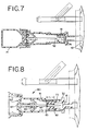
- the deactivated position, or post reconstitution position is the first container 12 and the second container 14 are not in fluid communication and have been moved from the activated position to the deactivated position (FIG. 7).
- the sleeve assembly 26 generally comprises a first sleeve 33 and a second sleeve 34.
- the first sleeve 33 and second sleeve 34 are mounted for translational motion with respect to one another from the inactivated position to the activated position.
- the first sleeve 33 is slidably mounted within the second sleeve 34.
- Each sleeve 33,34 has generally cylindrical walls and collectively the sleeves 33,34 define a central channel 31 through the connector 10.
- the first sleeve 33 has a first end 35 and a second end 36. The first end 35 is adapted to receive and be connected to the port connector 32.
- the second end 36 of the first sleeve 33 has an annular groove 39.
- the annular groove 39 receives a sealing member 40, preferably in the form of an O-ring.
- the O-ring 40 provides a seal between the first sleeve 33 and the second sleeve 34 and in a preferred form of the invention is disposed between the first sleeve 33 and the second sleeve 34.
- other sealing members such as gaskets, washers and similar devices could be used to achieve a seal between the sleeves 33,34 as is well known in the art without departing from the present invention.
- the first sleeve 33 further has a guide 41 at an inner surface of the sleeve 33, intermediate the first end 35 and the second end 36.
- the guide 41 has an opening 42 adapted to receive and support a portion of the piercing member 28 as will be described in greater detail below.
- the second sleeve 34 also has a first end 37 and a second end 38.
- the second end 38 of the second sleeve 34 defines a base 43 that is adapted to connect to the cup assembly 30.
- the second sleeve 34 accommodates the piercing assembly 28 within the passageway 31.
- the piercing assembly 28 is slidable within the passageway 31 along an inner surface of the second sleeve 34.
- the second sleeve 34 has a first section 44 and a second section 45.
- the second section 45 has a larger diameter than the first section 44.
- a ledge 46 is formed at the interface between the first section 44 and the second section 45.
- first sleeve 33 has a stop surface 47 that cooperates with a stop surface 48 on the second sleeve 34 that prevent the first sleeve 33 from sliding out of the second sleeve 34.
- the first sleeve 33 also has a top surface 49 that interfaces with the piercing assembly 28 as will be described in greater detail below.
- the piercing assembly 28 generally comprises a hub 50 that supports a piercing member 51.
- the piercing member 51 has a first end 52 that is positioned within the opening 42 of the guide 41 of the first sleeve 33 when in the inactivated position.
- a second end 53 of the piercing member is positioned adjacent the cup assembly 30 when in the inactivated position.
- the piercing member 51 such as a cannula or needle, is a rigid, elongate, spiked member at each end 52,53 having a central fluid passage 54 for establishing a fluid flow passage between the first container 12 and the second container 14.
- the piercing member is positioned outside the sidewalls of the first container 12 and is mounted thereto.
- Each end 52,53 of the piercing member 51 terminates in a sharp point or an oblique angle or bevel adapted to pierce through closures as will be described below.
- the hub 50 connected to the piercing member 51, is slideable within the passageway 31 along an inner surface of the second sleeve 34.
- the hub 50 has a generally round outer profile and is divided into segments.
- the hub has a greater diameter than the diameter of the first section 44 of the passageway 31 but a smaller diameter than the second section 45. Therefore, the hub 50 must be spring loaded into the first section 44. The spring-loading ensures the O-ring 40 has intimate contact with the first section 44.
- the piercing member 51 is allowed to move and pierce the closure of the drug vial 14 and pre-slit membrane 74 (described below) adjacent the flexible container 12 when the connector 10 moves from the inactivated position to the activated position.
- the hub 50 has a stepped configuration.
- the hub 50 has a first stop surface 55 that cooperates with the top surface 49 of the first sleeve 33.
- the hub 50 also has a second stop surface 56 that cooperates with the ledge 46 (FIGS. 2 and 6) on the second sleeve 34.
- the hub 50 further has an annular outer surface 57 that slides along the inner surface of the second sleeve 34. This allows the piercing assembly 28 to "float" within the second sleeve 34.
- FIG. 1 further shows the cup assembly 30.
- the cup assembly 30 is substantially identical to the cup assembly 130 shown in FIGS. 11-16.
- the cup assembly 30 generally includes a wall portion 58 having a connecting base 59, fingers 60 and a sealing member 61.
- the cup assembly 30 serves as an attaching member that is adapted to attach the cup assembly 30 to the second container or drug vial 14.
- the cup assembly 30 has a central opening 62.
- the wall portion 58 is preferably annular and forms a cup-like shape.
- the wall portion 58 is preferably continuous and solid.
- the connecting base 59 of the wall portion 58 is connected to the base 38 of the second sleeve 34.
- the wall portion 58 is connected to the base 38 by ultrasonic bonding.
- the wall portion 172 has bonding ribs (not shown in FIG. 1) which act to focus the ultrasonic bonding energy to the mating surfaces of the second sleeve base 38 and the connecting base 59 to heat and melt the surfaces, therefore, bonding the bases 38,59 together.
- the wall portion 58 supports means for fixedly attaching the second container or drug vial 14 to the cup assembly 30.
- the means shown are a plurality of segmented fingers 60.
- the fingers 60 are spaced inwardly from the wall portion 72 to allow the fingers 60 to flex when a drug vial 14 is inserted into the cup assembly 30.
- the fingers 60 are generally trapezoidal in shape and are separated by gaps to define a vial receiving chamber that corresponds to the central opening 62 of the cup assembly 30 for receiving a top of the vial 14.
- the present device utilizes six fingers 60, it can be appreciated by one of ordinary skill in the art that more or fewer fingers could be utilized without departing from the scope of the present invention. For example, eight fingers 60 could be used.
- all of the fingers 60 include a flat lead-in section 63, which helps to properly align the vial 14 to be properly aligned with the cup assembly 30.
- Three of the fingers 60, designated as 60a, include, adjacent to the flat lead-in section 63, radially inwardly tapering resilient tabs 64, from a distal end to a proximal end, past which the medical professional must urge a neck of the drug vial 14 in order to connect it to the cup assembly 30.
- the tabs 64 are capable of flexing to accommodate varying diameter vial closures.
- the distal end of the fingers 60 have a radiused end that is smooth to avoid cutting the medical personnel handling the connector.
- the tabs 64 could also be formed, however, as solid bumps without departing from the invention.
- the remaining three fingers 60b have axially extending, standing ribs 65 extending from a generally wedge shaped gusset as disclosed in greater detail in commonly-assigned Appln. Serial No. 08/986,580 which is incorporated herein by reference and made a part hereof.
- the gusset spaces the standing ribs 65 from an annular shelf.
- the front, axially-inward end of the gusset is essentially flush with the annular shelf.
- the gusset has an upwardly sloping deck from which the standing ribs 92 extend from a central portion thereof.
- the standing ribs 65 extend axially-outwardly beyond a distal end of the tabs 64 to assist in aligning the vial 14 with the vial receiving chamber during insertion.
- the standing ribs 65 are capable of indenting one or more sidewall portions of the metal crimp of the vial 14 in order to inhibit the vial 14 from rotating.
- a flexible retraining member such as shrink wrap or the like
- the sealing member 61 preferably in the form of a pierceable septum, is positioned within the space 66.
- the sealing member 61 and the O-ring 40 hermetically seal the piercing member along its entire length.
- other embodiments of the connector hermetically seal only piercing portions of the piercing member and fluid contacting portions of the piercing members and still achieve a hermetic fluid transfer.
- the sealing member 61 is positioned adjacent the second end 53 of the piercing member 51.
- the sealing member 61 is disk-shaped and has an annular ring 67 that extends axially from the disk and towards the top of the vial 14.
- the annular ring 67 is dimensioned to tightly and sealingly fit over an aperture of the vial 14 to prevent leakage from the vial 14.
- the annular ring 67 has an outwardly flaring sidewall 68 that forms a wiper seal with the closure of the vial 14.
- the annular ring 67 of the septum 61 is capable of deforming to accommodate dimensional variations in a height of a closure of the second container.
- the sealing member 61 can be pre-slit at a central location corresponding to the sharp point of the piercing member 52.
- the sealing member 61 has a central opening.
- the central opening receives the piercing member 51 when the connector 10 is moved from its inactivated position to the activated position.
- the central opening would also allow for steam sterilization past the sealing member 61.
- the sealing member 61 is lubricated, which lubricates the piercing member 51 allowing it to enter the drug vial 14 more easily.
- the sealing member 61 is preferably made from Silicone PL-S 146.
- a seal material 70 is preferably heat sealed to the wall portion 58 and is releasably secured thereto so that it can be peeled away by pulling a tear tab.
- the wall portion 58 provides for a solid surface to mount the seal material 70 therefore hermitically sealing the connector 10.
- the seal material could be made of aluminum foil, or of polymeric based material such as TYVEK®, and more preferably TYVEK® grade 1073B , or spun paper or other material that is capable of being peelably attached to the wall portion 58 and capable of providing a barrier to the ingress of contaminants. It is also contemplated that sealing can be accomplished through induction welding or other sealing techniques.
- the seal material 70 is made from TYVEK® and is adhesively connected to the wall portion 58.
- TYVEK® allows for steam to pass therethrough for sterilization purposes and for pressure relief that may be generated in the device during the steam sterilization process.
- the port connector 32 has a central base 71 dividing a first portion 72 and a second portion 73.
- the first portion 72 and the second portion 73 are generally cylindrical.
- the second portion 73 is connected, preferably by solvent bonding, to an inner surface of the first sleeve 33.
- a septum or more preferably a pre-slit rubber membrane, or disk 74 is optionally positioned between the guide 41 of the first sleeve 33 and the central base 71 of the port connector 32.
- the disk 74 prevents "drip-back" after activation as will be described in greater detail below.
- the disk 74 prevents fluid from the flexible container 12 from passing into the central passageway 31 without penetration from the piercing member 51.
- the fluid container 12 It is also possible to seal the fluid container 12 with a standard membrane in the port tube 16. In this instance it may be preferable to use a plastic piercing member for piercing the membrane.
- the port connector 32 is then connected to the flexible bag 12 wherein an outer surface of the first portion 72 is connected, preferably by solvent bonding, to an inner surface of the port 16.
- the connector 10 is connected to the flexible bag 12 prior to shipping. It will be appreciated by one of ordinary skill in the art, however, that the connector 10 could be connected to the first container 12 at different times.
- FIG. 1 shows the connector 10 in its inactivated position where the connector 10 is in its most elongated state wherein the stop surface 47 of the first sleeve 33 abuts the stop surface 48 of the second sleeve 34.
- FIGS. 3-7 disclose the activation process for the connector 10. As shown in FIG. 3, the seal material 70 is first removed and the drug vial 14 is then inserted into the cup assembly 30 wherein the fingers 60a engage the vial 14 to fixedly attach the vial 14 to the connector 10. The annular ring 67 of the sealing member 61 forms a fluid tight seal over the top of the vial 14. Thus, a vial 14 can be selectively attached without piercing the closure 22 of the vial 14. As further shown in FIG. 3, the second end 53 of the piercing member 51 is positioned very close to the sealing member 61 of the cup assembly 30. This reduces the stroke length or distance the piercing member 51 must travel to pierce the closure 22 of the drug vial 14.
- the first sleeve 33 is rotated relative to the second sleeve 34 to an unlocked position.
- the vial 14 in the cup assembly 30, along with the second sleeve 34, are moved axially towards the flexible container 12.
- the second end 53 of the piercing member 51 makes contact with the sealing member 61.
- the second sleeve 34 advances further towards the flexible bag 12 (FIG. 5)
- the second end 53 of the piercing member 51 pierces through the sealing member 61 and into the closure of the vial 14.
- the second end 53 of the piercing member 51 experiences greater friction as it penetrates the closure of the vial 14. This friction results in the first end 52 of the piercing member 51 to advance towards the flexible container 12 and piercing the rubber disk 74.
- the guide 41 assures that the first end 42 is properly aligned.
- FIG. 6 As shown in FIG. 6, as the second sleeve 34 advances further towards the flexible container 12, the top surface 49 of the first sleeve 33 abuts the first stop surface 55 of the hub 50 and advances the hub 50 against the sealing member 61: also, the first end 37 of the second sleeve 34 proceeds to the first end 35 of the first sleeve 33.
- This position (FIG. 6) represents the activated position. In the activated position, the second end 53 of the piercing member 51 is pierced through the closure 22 of the vial 14, and the first end 52 of the piercing member 51 is pierced through the rubber disk 74. Thus, fluid communication is established between the flexible bag 12 and the vial 14 through the passageway 54 of the piercing member 51.
- the central passageway 31 is sealed in a substantially air-tight fashion at one end by the sealing member 61, at an opposite end by the rubber disk 74 and at the interface between the sleeves 33,34 by the O-ring 40.
- the volume of the passageway 31 necessarily decreases thus pressurizing the air located in the passageway 31. This pressurized air must be relieved before the connector reaches the final activated position.
- the O-ring 40 moves past the first section 44 of the second sleeve 34 to the larger diameter second section 45 of the second sleeve 34, the O-ring no longer contacts the inner surface of the second sleeve 34 (FIG. 6) thus allowing the pressurized air to be relieved.
- the diluent contained in the flexible container 12 can pass through the piercing member 51 to reconstitute the drug contained in the vial 14.
- the drug vial 14 and second sleeve 34 can be pulled back away from the flexible container 12.
- the second end 53 of the piercing member 51 remains in the closure of the vial 14 and the second end 52 of the piercing member 51 is pulled past the rubber disk 74 (FIG. 7).
- This position is referred to as the deactivated position, or post reconstitution position.
- the rubber disk 74 is resilient and seals up thus preventing any of the resulting mixture from dripping back into the drug vial 14.
- FIG. 8 discloses another embodiment of the connector device of the present invention generally referred to with the reference numeral 80.
- the connector device 80 is similar to the connector device 10 of FIGS. 1-7. Identical elements will be referred to with identical reference numerals.
- the connector device 80 does not utilize the rubber disk 74 or guide 41 used in the connector device 10.
- the connector device 80 does utilize an "x-ring” gasket 81 that seals off the flexible container 12.
- the gasket 81 is referred to as an "x-ring” gasket or sometimes as an annular "dog-bone” gasket because its cross-sectional shape resembles these shapes.
- the x-ring gasket 81 has a first end 82 and a second end 83 and supports an end of the piercing member and forms a hermetic seal from its second end 83 to the container.
- the gasket 81 and the sealing member 84 described below, hermetically seal piercing portions of the piercing member and fluid contacting portions of the piercing member.
- the x-ring gasket 81 is positioned within the first sleeve 33 wherein its first end 82 is adjacent the second portion 73 of the port connector 32. Thus, the diluent of the flexible container 12 are allowed to travel through the port 16 up but only up to the first end 82 of the x-ring gasket 81.
- the diluent is allowed to travel through the piercing member 51 but only up to a sealing member 84 as will be described below.
- the x-ring gasket 81 has a length L that is longer than the distance the piercing member 51 will travel when moving from the inactivated position to the activated position. This ensures that, upon activation, the stroke of the piercing member 51 is such that the mark 86 does not pass beyond the first end 82 of the x-ring gasket 81 towards the flexible container 12. Therefore, only hermetically sealed portions of the piercing member are allowed to pierce the closures of the first and second containers and to contact the fluid being communicated.
- the connector 80 also utilizes a sealing member 84 similar to the sealing member 61.
- the sealing member 84 has an elongated sheath 85.
- the elongated sheath 85 covers and hermetically seals the second end 53 of the piercing member 51.
- the sealing member 84 has a surface 87 that seals off the diluent in the flexible container 12 until the piercing member 51 pierces the closure of the drug vial 14.
- FIG. 9 shows the connector device 80 in the activated position. Similar to the connector device 10, a single force is applied to the connector 80 to place the connector 80 in the activated position. After the sleeves 33,34 are rotated to an unlocked position, a force is applied to the vial 14 wherein the vial 14 and the second sleeve 34 moves toward the flexible container 12; and the first end 52 of the piercing member 51 moves further past the x-ring gasket 81. The top surface 49 of the first sleeve 33 forces the piercing assembly 28 towards the vial 14 wherein the piercing member 51 pierces the surface 87 of the sealing member 84 and the closure of the vial 14. Thus, fluid communication is established between the flexible bag 12 and the drug vial 14.
- FIG. 10 discloses another embodiment of the connector device of the present invention generally referred to with the reference numeral 90.
- the connector device 90 is similar to the connector devices 10,80 of FIGS. 1-9. Identical elements will be referred to with identical reference numerals.
- the connector device 90 has a modified cup assembly 91 comprising only a connecting portion 92 and fingers 93.
- the cup assembly 91 does not have an annular wall portion 58 or the sealing member 70. Rather, a pull-off tab 94 is utilized.
- the pull-off tab 94 is snap-fitted to the cup assembly 91 adjacent the sealing member 84. When it is desired to reconstitute a drug, the pull-off tab 94 is pulled off and a drug vial 14 is inserted into the cup assembly 91. Activation is accomplished as described above.
- FIGS. 11-16 disclosed another embodiment of a connector device of the present invention, generally referred to with the reference numeral 100. Similar to the previous embodiments, the connector 100 is adapted to connect to both the flexible bag 12 and the vial 14 and place the contents of the flexible bag 12 and the vial 14 into fluid communication with one another. As shown in FIGS. 11 and 12, the connector 100 generally comprises a sleeve 126, a piercing assembly 128 and a cup assembly 130. The sleeve 126 and cup assembly 130 are adapted for axial movement with respect to the piercing assembly 128 from an inactivated position (FIG. 15) to an activated position (FIG. 16).
- the sleeve 126 has a first end 132 and a second end 134 with an elongate sheath 136 between the ends 132,134 defining a passageway 135.
- the sleeve 126 is deformable wherein the sheath 136 can fold onto itself when a force is applied towards the first end 32 along a longitudinal axis of the sleeve 26.
- the sleeve 126 may sometimes be referred to as a rolling diaphragm because of the way in which it deforms and folds upon itself.
- the sleeve 126 can be made from a flexible material such as a thermoplastic material including PVC and polyolefins.
- the sleeve 126 has a first section 138 and a second section 140.
- the first section 138 has a greater diameter than the second section 140.
- the first end 132 of the sleeve 126 has a first rim 142 and a second rim 144.
- the second rim 144 is concentric with, and spaced inward from the first rim 142.
- An annular slot 146 (FIG. 13) is defined between the rims 142,144.
- the second end 134 of the sleeve 126 has an annular surface 148 adapted to be connected to the cup assembly 130 as described below.
- the second end 134 of the sleeve 126 is sealed by a membrane 150.
- the membrane 150 is formed integral with the sleeve 126 such as by injection molding although it could be separately attached without departing from the scope of the invention.
- a coining operation is applied to the membrane 150 to reduce the cross-sectional thickness of the membrane 150. This allows the piercing member 128 to more easily pierce the membrane 150.
- the piercing assembly 128 generally includes a piercing member 152 connected to a collar 154.
- the piercing member 152 is connected to the collar 154 in an interference fit although other connections are possible such as by bonding.
- the piercing member 152 and collar 154 can be integrally molded in a single piece. It is also understood that the piercing assembly 128 could comprise only the piercing member 152 without the collar 154.
- the piercing member 152 such as a cannula or needle, is a rigid, elongate, spiked member having a central fluid passage 156 therethrough for establishing a fluid flow passage between the first container 12 and the second container 14.
- the piercing member 152 terminates in a sharp point 153 or an oblique angle or bevel and is adapted to pierce the rubber stopper 22 of the drug vial 14.
- the piercing member 152 is made from polycarbonate PL-2368 but can also be made from other plastics or metal.
- the end of the piercing member 152 ending in the sharp point 153 can have a slot 155 to allow for a larger opening for draining the vial 14 during reconstitution.
- the piercing member 152 has radial slots 157 at one end that are spaced from the central fluid flow passage 156. The slots 157 allow for contents of the first container 12 to pass through the slots 157 and into the sleeve 126.
- the piercing member 152 has a flange 158 towards one end for contacting the first end 132 of the sleeve 126.
- the collar 154 serves as a base portion for the connector device 100.
- the collar 154 has a flange 160 and a central opening 162 through the flange 160.
- the collar 154 further has an annular ridge 164 extending from the flange 160.
- the piercing assembly 128 is connected to the sleeve 126.
- the piercing member 152 is positioned within the passageway 135 of the sleeve 126, and specifically within the sheath 136.
- the collar 154 is connected to the sleeve 126 wherein the annular slot 146 receives the annular ridge 164.
- the annular ridge 164 is solvent bonded to the rims 142,144.
- the flange 158 of the piercing member 152 is also bonded to the sleeve 126. The solvent bonding in this configuration hermetically seals the sleeve 126 to the collar 154.
- Solvent bonding is preferable because it is more reliable than other types of connections such as interference fits or threaded connections.
- the outer surface of the piercing member 152 is in surface-to-surface contact with an inner surface of the sleeve 126 at the second section 140. Because the first section 138 has a greater diameter than the second section 140, a pocket 139 (FIG. 14) is maintained between the sleeve 126 and piercing member 152 at the first section 138. The pointed end of the piercing member 152 is positioned adjacent the membrane 150.
- the outer surface of the collar 154 is adapted to be received in the port 16 of the flexible bag 12.
- the collar 154 is preferably solvent bonded in the port 16.
- the piercing member 152 is hermetically sealed at both of its ends.
- the blunt end is hermetically sealed by the port 16 of the flexible container 12 and the pointed end 153 is hermetically sealed by the membrane 150.
- contents of the first container 12 can pass from the container 12, through the passageway 156 and up to the membrane 150.
- the contents can also pass from the container 12, through the radial slots 157 and into the passageway 135 at the first section 138 of the sleeve 126.
- the contents can fill the pocket 139 contacting an inner surface of the sleeve 126.
- the liquid within the first section 138 provides for greater conduction of the sterilization energy provided when the connector 100 is placed in an autoclave.
- FIGS. 12-14 show the cup assembly 130.
- the cup assembly 130 generally includes a base 170, a wall portion 172, fingers 174 and a sealing member 176.
- the cup assembly 130 serves as an attaching member that is adapted to attach the assembly 130 to the second container or drug vial 14.
- the base 170 is disk-shaped having a center opening 178 therethrough.
- the wall portion 172 is preferably annular and is connected to an outer periphery of the base 170 forming a cup-like shape.
- the wall portion 172 is preferably continuous and solid.
- the wall portion 172 is connected to the base 170 by ultrasonic bonding. As shown in FIG.
- the wall portion 172 has bonding ribs 175 which act to focus the ultrasonic bonding energy to the mating surfaces of the base 170 and the wall portion 172 to heat and melt the surfaces, therefore, bonding the base 170 and wall portion 172 together.
- This two-piece assembly, along with the sealing member 176 act to prevent microbes from contaminating the connector 100.
- a flash trap is provided between the base 170 and wall portion 172 to catch material from the ultrasonic bonding.
- the cup assembly 130 is attached to the second end 134 of the sleeve 126.
- the base 170 is solvent bonded to the second end 134 of the sleeve 126.
- This connection requires bonding a polycarbonate material (base 170) to a vinyl material (sheath 126).
- the bonding agent used is typically methyl-ethyl-ketone (MEK).
- MEK methyl-ethyl-ketone
- the wall portion 172 supports means for fixedly attaching the second container or drug vial 14 to the cup assembly 130.
- the means shown are a plurality of segmented fingers 174 (FIGS. 12 and 13).
- the fingers 174 are spaced inwardly from the wall portion 172 to allow the fingers 174 to flex when a drug vial 14 is inserted into the cup assembly 130.
- the fingers 174 are generally trapezoidal in shape and are separated by gaps 184 (FIG. 11) to define a vial receiving chamber 186 for receiving a top of the vial 14.
- the present device utilizes six fingers 174, it can be appreciated by one of ordinary skill in the art that more or fewer fingers could be utilized without departing from the scope of the present invention.
- all of the fingers 174 include a flat lead-in section 177, which helps to properly align the vial 14 to be properly aligned with the cup assembly 130.
- Three of the fingers 174, designated as 174a, include, adjacent to the flat lead-in section 177, radially inwardly tapering resilient tabs 188, from a distal end to a proximal end, past which the medical professional must urge a neck of the drug vial 14 in order to connect it to the cup assembly 130.
- the tabs 188 are capable of flexing to accommodate varying diameter vial closures.
- the distal end of the fingers 174 have a radiused end that is smooth to avoid cutting the medical personnel handling the connector.
- the tabs 188 shown have a space 189 between the distal end of the tab and the finger 174.
- the tabs 188 could also be formed, however, as solid bumps without departing from the invention.
- the remaining three fingers 174b have axially extending, standing ribs 192 extending from a generally wedge shaped gusset as disclosed in greater detail in commonly-assigned Appln. Serial No. 08/986,580.
- the gusset spaces the standing ribs 192 from the annular shelf 197.
- the front, axially-inward end of the gusset is essentially flush with the annular shelf.
- the gusset has an upwardly sloping deck from which the standing ribs 192 extend from a central portion thereof.
- the standing ribs 192 extend axially-outwardly beyond a distal end of the tabs 188 to assist in aligning the vial 14 with the vial receiving chamber during insertion.
- the standing ribs 192 are capable of indenting one or more sidewall portions of the metal crimp of the vial 14 in order to inhibit the vial 14 from rotating.
- a flexible retraining member such as shrink wrap or the like
- the sealing member 176 preferably in the form of a pierceable septum, is positioned within the space 180.
- the sealing member 176 covers the center opening 178 and is adjacent to the membrane 150.
- the sealing member 176 is disk-shaped and has an annular ring 194 that extends axially from the disk and towards the top of the vial 14. The annular ring 194 is dimensioned to tightly and sealingly fit over an aperture of the vial 14 to prevent leakage from the vial 14.
- the annular ridge 194 has an outwardly flaring sidewall 195 that forms a wiper seal with the closure of the vial 14.
- the annular ring 194 of the septum 176 is capable of deforming to accommodate dimensional variations in a height of a closure of the second container.
- the sealing member 176 can be a solid septum or a pre-slit septum, or a septum having a portion removed to define a central opening 198 corresponding to the sharp point of the piercing member 152.
- Most preferably the sealing member 176 has the central opening 198.
- the central opening 198 receives the piercing member 152 when the sleeve 126 is moved from its inactivated position to the activated position.
- the central opening 198 also allows for steam sterilization past the sealing member 176.
- the sealing member 176 is lubricated, which lubricates the piercing member 152 allowing it to enter the drug vial 14 more easily.
- the sealing member 176 is preferably made from Silicone PL-5146.
- a seal material 90 is preferably heat sealed to the wall portion 172 and is releasably secured thereto so that it can be peeled away by pulling a tear tab 192.
- the wall portion 172 provides for a solid surface to mount the seal 190 therefore hermitically sealing the connector 100.
- the seal could be made of aluminum foil, or of polymeric based material such as TYVEK®, or spun paper or other material that is capable of being peelably attached to the wall portion 172 and capable of providing a barrier to the ingress of contaminants. It is also contemplated that sealing can be accomplished through induction welding or other sealing techniques.
- the seal material 190 is made from TYVEK® and is adhesively connected to the wall portion 172. Use of TYVEK® allows for steam to pass therethrough for sterilization purposes.
- the connector 100 may include a slip ring 99 to prevent inadvertent actuation.
- the slip ring 199 is tightly wrapped around the sleeve 126 preventing movement of the sleeve 126 with respect to the piercing member 152.
- the slip ring 199 is frangibly attached around the sleeve 126 allowing for easy removal prior to activation of the connector.100.
- FIG. 14 shows the connector 100 in its inactivated position where the sleeve 126 is in a general elongated state.
- the connector 100 is adapted to be connected to the first container 12.
- the outer surface of the collar 154 is bonded to the inner surface of the port 16.
- the connector 10 could be connected to the first container 12 at different times.
- the seal 190 is removed and the drug vial 14 is then inserted into the cup assembly 130 wherein the fingers 174a engage the vial 14 to fixedly attach the vial 14 to the connector 100.
- the annular ring 194 of the sealing member 176 forms a fluid tight seal over the top of the vial 14.
- the slip ring 100 As shown in FIG. 16, to place the connector 100 in an activated position, the slip ring 100, if utilized on the connector 100, is removed. A medical professional then pushes the drug vial 14 towards the flexible bag 12.
- the sheath 136 of the deformable sleeve 126 rolls and folds over itself.
- the second section 140 slides along the piercing member 152 in frictional engagement and the first section 138 folds over the second section 140 making the sheath 136 approximately half its original length.
- the piercing member 152 pierces through the membrane 150, passes through the central opening 197 of the sealing member 176 and the rubber stopper 122 of the vial 14.
- the flexible bag 12 is placed in fluid communication with the drug vial 14.
- the first container 12 and the second container 14 are in fluid communication.
- the medical professional will then squeeze the flexible bag 12 to force the fluid into the vial 14 to reconstitute the drug, shaking the vial 14 as necessary to facilitate reconstitution, and inverting the vial 14 in relation to the bag 12 to allow the reconstituted drug to flow back into the bag 12.
- the sleeve 126 encapsulates the piercing member 152.
- the membrane 150 encloses one end of the piercing member 152 and the first container 12 encloses the other end of the piercing member 152.
- the piercing member 152 is independently hermetically sealed.
- the sleeve 126 is rigid enough to support the cup assembly 130 and attached drug vial 14.
- the sleeve 126 is also flexible enough to deform and fold upon itself to allow for easy insertion of the piercing member 152 into the drug vial 14.
- This configuration also provides ready visual determination if the connector 10 has been activated.
- the seal 190 also is tamper evident. Also with this configuration, the integrity of the drug vial is maintained until the connector 100 is moved to its activated position.
- preattach the vial 14 to the connector 100 for shipment.
- Preattaching the vial 14 to the connector 100 may be accomplished using aseptic connecting techniques.
- the preferred method of preattaching the device 100 to the vial 14 include the steps of: 1) positioning the vial 14 and the cup assembly 130 into opposed relationship, 2) simultaneously bringing the segmented fingers 174 into operative engagement with the vial 14 while sterilizing the connection by exposing the connecting portions of the device 100 and the vial 14 with, preferably, gamma sterilization or other sterilization energies or techniques. These steps can be carried out manually by medical personnel or automatically by a machine.
- the preattached vial 14 and connector 100 may be wrapped in an over pouch for shipping and storage. An over pouch, however, is typically not used with the connector 100 thus saving in material costs.
- FIGS. 17 and 18 disclose another embodiment of the connector device of the present invention generally referred to with the reference numeral 200.
- the connector device 200 of FIGS. 17 and 18 is similar to the connector device 100 of FIGS. 11-16 and identical elements will be referred to with identical reference numerals.
- the connector device utilizes a deformable bellows assembly 202.
- the bellows assembly 202 is preferably made of a vinyl material.
- the bellows assembly 202 has a first end 204 and a second end 206 having a bellows portion 208 therebetween.
- the first end 204 is connected to the collar 154 of the piercing assembly 128.
- the second end 206 is connected to the cup assembly 130.
- diluent from the flexible container 12 can pass through the piercing member 152 and into the passageway 135.
- FIG. 18 shows the connector device 200 in the activated position.
- the activation process is similar to that described above.
- the second end 206 of the bellows assembly 202 slides along the piercing member 152, and the bellows portion 208 folds in accordion-like fashion.
- the piercing member 152 pierces through the membrane 150 and septum 176 and into the closure of the vial 14, thus establishing fluid communication between the flexible bag 12 and the vial 14.
- FIGS. 19 and 20 disclose yet another embodiment of the connector device of the present invention generally referred to with the reference numeral 250.
- This connector device 250 of FIGS. 19 and 20 is similar to the connector devices 200 of FIGS. 17 and 18 and FIGS. 11-16 and identical elements will be referred to with identical reference numerals.
- the connector device 250 utilizes a deformable bellows assembly 252, preferably made of a vinyl material.
- the bellows assembly 252 has a first end 254 and a second end 256 having a first bellows portion 258 and a second bellows portion 260 therebetween.
- the first end 254 is connected to a port connector 262.
- the port connector 262 is connected to the port 16 of the flexible container 12.
- the second end 256 is connected to the cup assembly 130.
- the connector device 250 utilizes a different type of piercing assembly 264.
- the piercing assembly 264 generally comprises a hub 266, a first piercing member 268 and a second piercing member 270.
- the first piercing member 268 is preferably made of polycarbonate and is adapted to pierce a membrane 272 that seals the flexible container 12.
- the second piercing member 270 is preferably made of metal and is adapted to pierce a sealing member 274 and a closure of the vial 14.
- the first and second piercing members 268,270 are overmolded into the hub 266. As further shown in FIG.
- the hub 264 is connected to an intermediate portion 276 of the bellows assembly 252 between the first bellows portion 258 and the second bellows portion 260.
- This connection is preferably a solvent bond.
- the piercing assembly 264 is fixedly secured to the bellows assembly 252 and therefore moves therewith.
- FIG 20 shows the connector device 250 in the activated position.
- the activation process is similar to that described above.
- the second bellows portion 260 folds in accordion-like fashion wherein the second piercing member 270 pierces through the sealing member 274 and closure of the vial 14.
- the first bellows portion 254 folds in accordion-like fashion wherein the first piercing member pierces through the membrane 272. Accordingly, fluid communication is established between the flexible container 12 and the vial 14 via the piercing assembly 264.
- the second piercing member 270 can be withdrawn from the vial 14 and the first piercing member 268 can be withdrawn from the port 16.
- the sealing member 176 will seal itself thus preventing any drip-back from the flexible container after reconstitution is complete.
- diluent from the flexible container 12 is prevented from contacting the surface of the bellows assembly 252.
- the use of the two bellows portions 258, 260 provides dual control. The operator of the device can pierce the vial 14 before the flexible bag 12 or vice-versa.
- the connector devices of the present invention can be sterilized by known procedures such as steam sterilization or radiation sterilization. Also, it is understood that any of the features of the different embodiments of the connector devices described above can be combined or eliminated as desired. It should also be understood that each of the devices of the present invention allow for pre-attaching a vial to the connector and shrink wrapping the two to provide a tamper evident feature.
- the present invention provides a connector device for establishing fluid communication between a liquid container having sidewalls and a drug vial having a neck with a closure therein.
- the connector comprises: a piercing member having a first end and a second end and a central fluid pathway, the piercing member being mounted to the liquid container and having fluid accessing portions hermetically sealed from an outside environment, a vial receiving chamber associated with the piercing member and being dimensioned to connect to the vial and wherein a vial may be selectively attached to the device without piercing the closure of the vial and without breaching the hermetic seal of the fluid accessing portions of the piercing member and means for connecting the vial receiving chamber to the liquid container.
- the device is movable from an inactivated position where the piercing member is outside the sidewalls and no fluid flows between the liquid container and the drug vial, to an activated position wherein fluid flows through the fluid pathway between the liquid container and the drug vial, the device being movable from the inactivated position to the activated position by a force applied to the device outside the liquid container.
- the liquid container may be a syringe.
- the means for connecting the vial receiving chamber to the liquid container comprises a first sleeve and a second sleeve mounted for translational motion with respect to one another, the first sleeve being connected to the liquid container and the second sleeve being connected to the vial receiving chamber.
- the first sleeve is mounted within the second sleeve.
- the second sleeve slidably mounts the piercing member for translational motion.
- the second sleeve preferably has an inner surface and the piercing member is capable of sliding on the inner surface.
- a hub may mount the piercing member inside the second sleeve.
- the device may further comprise means disposed between the first sleeve member and the second sleeve member for sealing the first sleeve member and the second sleeve member.
- the means for connecting the vial receiving chamber to the liquid container may comprise a flexible sleeve having a first end and a second end and defining a central passageway, the piercing member being positioned within the passageway, and the sleeve being slidable with respect to the piercing member from the inactivated position to the activated position wherein the sleeve slides along the piercing member and folds upon itself, the piercing member piercing a closure of the vial establishing fluid communication between the liquid container and the vial.
- the sleeve preferably has a first section and a second section, the first section having a greater diameter than the second section, wherein when the sleeve moves from the inactivated position to the activated position, the second section slides along the piercing member and the first section folds upon the second section.
- the vial receiving chamber may comprise a base connected to a wall portion, the wall portion having a plurality of fingers inwardly spaced from the wall portion and adapted to cooperatively receive the vial, the base being connected to the sleeve.
- a sealing member may be positioned between a bottom portion of each finger and the base.
- the sealing member is a pierceable septum.
- the septum comprises a disk with the piercing member passing through the disk when the sleeve is moved from the inactivated position to the activated position.
- the disk may further have a generally centrally disposed annular ring extending axially from the disk, the annular ring being dimensioned to fit over a closure of the second container.
- the septum may be capable of deforming to accommodate dimensional variations in a height of the closure of the vial.
- the piercing member may have a radial slot spaced from the fluid flow passage allowing contents of the liquid container to pass through the radial slot and into contact with an inner surface of the sleeve.
- the present invention also provides a connector device for establishing fluid communication between a liquid container and a vial container comprising: a first sleeve and a second sleeve mounted for translational movement with respect to one another and defining a central channel therein, the first sleeve and the second sleeve each having an inner surface, the first sleeve being adapted to attach to the liquid container, a piercing member having opposed piercing ends, the piercing member being mounted in the central channel, means for hermetically sealing the piercing ends when the device is connected to the first container and the second container, and a vial receiving chamber on the second sleeve which is dim- ensioned-to, connect to the vial and wherein the vial may be selectively attached to the device without piercing the closure of the vial and without breaching the hermetic seal of the piercing ends.
- the first sleeve and the second sleeve are capable of being moved from an inactivated position where fluid cannot flow through the device to an activated position where fluid can flow through the device.
- the device is capable of being moved from the inactivated position to the activated position by applying a force to the device outside the first container and the second container.
- the means for hermetically sealing comprises a sealing member disposed between the first sleeve and the second sleeve.
- the first sleeve is mounted within the second sleeve and the sealing member is mounted on the first member and slides along the inner surface of the second sleeve.
- the means for sealing may comprise a septum mounted within the vial receiving chamber to seal the second sleeve.
- the device may further comprise means for venting the device when the device is moved from the inactivated position to the activated position.
- the means for venting may comprise an increased inner diameter portion of the second sleeve proximate a distal end of the second sleeve and upon which the sealing member does not seal.
- the device may further comprise means for supporting the piercing member within the central channel.
- the means for supporting may comprise a hub that mounts the piercing member and that comprises a portion that slides on the inner surface of the second sleeve.
- the hub may mount the piercing member along a generally central portion of the piercing member.
- the means for mounting the piercing member may further comprise a guide within the first sleeve that supports a portion of the piercing member.
- the guide is preferably positioned adjacent the liquid container.
- the device may further comprise a disk positioned between the liquid container and the guide.
- the device is capable of being positioned between an activated position and a deactivated position wherein in the deactivated position the first end of the piercing member is pulled out of the disk and guide.
- the means for hermetically sealing may comprise a first means for sealing the first sleeve and a second means for sealing the second sleeve.
- the first sealing means may comprise an annular gasket positioned in the first sleeve.
- the annular gasket supports a portion of the piercing member.
- the piercing member travels a distance when the device is moved from the inactivated position to the activated position and the annular gasket has a length that is greater than that distance.
- the annular gasket preferably has an X-shaped cross section.
- the means for sealing the second sleeve may comprise a septum.
- the septum preferably is positioned within the vial receiving chamber.
- the septum has a generally disk shaped portion.
- the septum may further comprise a sheath extending axially away from the septum which is dimensioned to fit over one of the piercing ends of the piercing member.
- the sheath may have an enlarged distal end that is dimensioned to fit over a portion of a hub that mounts the piercing member.
- the present invention also provides a connector device for establishing fluid communication between a first container and a second container comprising: a sleeve having a first end and a second end, a piercing member connected to the first end of the sleeve and adapted to be connected to the first container, the piercing member being positioned within the sleeve and providing a fluid flow passage from the first container to the second container, the piercing member further having a radial slot allowing contents of the first container to pass through the radial slot and into contact with an inner surface of the sleeve and a cup assembly connected to the second end of the sleeve, the cup assembly being adapted to be attached to the second container.
- the sleeve is slidable with respect to the piercing member from an inactivated position to an activated position wherein the sleeve slides along the piercing member and folds upon itself, the piercing member piercing a closure of the second container establishing fluid communication between the first container and the second container.
- the sleeve preferably has a first section and a second section, the first section having a greater diameter than the second section wherein a pocket is maintained between the piercing member and the first section, and wherein the contents of the first container pass through the radial slot and into the pocket.
- the present invention also provides a connector device for establishing fluid communication between a first container and a second container comprising: a sleeve having a first end and a second end, a piercing member connected to the first end of the sleeve and adapted to be connected to the first container, the piercing member being positioned within the sleeve and providing a fluid flow passage from the first container to the second container, and a cup assembly having a base connected to a wall portion, the wall portion having a plurality of fingers inwardly spaced from the wall portion and adapted to cooperatively receive the second container, the base being connected to the second end of the sleeve.
- the sleeve is slidable with respect to the piercing member from an inactivated position to an activated position wherein the sleeve slides along the piercing member and folds upon itself, the piercing member piercing a closure of the second container establishing fluid communication between the first container and the second container.
- the device may further comprise a sealing member positioned between a bottom portion of each finger and the base.
- the sealing member is a pierceable septum.
- the septum may comprise a disk having a central opening that receives the piercing member when the sleeve is moved from the inactivated position to the activated position.
- the disk further has a centrally disposed annular ring extending axially from the disk, the annular ring being dimensioned to fit over a closure of the second container.
- the septum is capable of deforming to accommodate dimensional variations in a height of a closure of the second container.
- the present invention also provides a connector device for establishing fluid communication between a first container and a second container comprising: a sleeve having a first end and a second end, the first end having an annular slot and the second end being sealed by a membrane, a collar which is adapted to be attached to the first container, said collar having an annular ridge and being connected to the sleeve wherein the annular slot receives the annular ridge, a piercing member supported by the collar and positioned within the sleeve and the collar, the piercing member providing a fluid flow passage from the first container to the second container, and a cup assembly connected to the second end of the sleeve, the cup assembly supporting a pierceable septum and being adapted to be attached to the second container.
- the piercing member is slideable with respect to the sleeve from an inactivated position to an activated position wherein the sleeve moves along the piercing member folding upon itself, the piercing member piercing the membrane, septum and closure of a second container establishing fluid communication between the first container and the second container.
- the present invention also provides a connector device for establishing fluid communication between a flexible solution container and a drug vial comprising: a sleeve having a first section and a second section, the first section having a greater diameter than the second section, the second section being sealed by a membrane and the first section having an annular slot, a collar having an opening and an annular ridge around the opening and being connected to the sleeve wherein the annular slot receives the annular ridge, the collar being attached to the flexible solution container, a piercing member having a blunt end and another end having a sharp point, the piercing member being positioned within the sleeve wherein the blunt end is positioned in the collar opening and the sharp point is positioned adjacent the membrane, the second section being in surface-to-surface contact with the piercing member and the piercing member providing a fluid flow path from the flexible container to the drug vial, a cup assembly having a base connected to a wall portion, the base being connected to the second section of the
- the sleeve is movable from an inactivated position to an activated position by applying a force to move the drug vial toward the piercing member wherein the second section of the sleeve moves along the piercing member and the first section folds over the second section, the piercing member piercing the membrane, passing through the central opening of the septum and piercing a closure of the drug vial thereby establishing fluid communication between the first container and the second container.
- the present invention also provides a connector device for establishing fluid communication between a first container and second container comprising: a bellows assembly having a first end and a second end, the bellows assembly having a first bellows portion and a second bellows portion and an intermediate section therebetween, a port connector having one end connected to the first end of the bellows assembly and another end adapted to be attached to the first container, the port connector having a membrane, an attaching member attached to the second end of the bellows assembly, the attaching member adapted to be attached to the second container, and a piercing assembly positioned within the bellows assembly, the piercing assembly having a hub supporting a first piercing member and a second piercing member, the hub being fixedly attached to the intermediate portion, the piercing assembly providing a fluid flow passage between the first container and the second container.
- the bellows assembly is deformable from an inactivated position to an activated position wherein the second piercing member is adapted to pierce the second container and the first piercing member is adapted to pierce the membrane to establish fluid communication between the first container and the second container.
- the second container is capable of being pierced by the second piercing member independently, of the first piercing member piercing the membrane.
- the present invention also provides a device for connecting to a vial having a closure comprising: a connecting base, a plurality of segmented fingers circumferentially spaced and axially extending from the base, the segmented fingers defining a receiving chamber dimensioned to accommodate the closure of the vial, wherein the fingers have a proximal end and a distal end, and an annular wall circumjacent the segmented fingers.
- the segmented fingers are spaced a distance therefrom to define an annular space between.
- at least one of the fingers has a standing rib.
- a plurality of the fingers have standing ribs.
- the standing ribs may taper radially inwardly proximate the distal end of the fingers.
- At least one of the fingers may have a lead-in section.
- a radially-inwardly tapering tab may extend from the lead-in section.
- a plurality of the fingers have radially inwardly tapering tabs extending from a lead-in section.
- a plurality of fingers have standing ribs and a plurality of fingers have radially inwardly tapering tabs extending from a lead-in section wherein the fingers with the tabs and the fingers with the ribs are disposed in alternating order about the receiving chamber.
- the distance between the annular wall and the fingers is preferably dimensioned to allow the fingers to flex when receiving a vial.
- the annular wall is continuous and solid.
- the device may further comprise a seal material releasably secured to the annular wall.
- the seal material may be selected from the group consisting of a foil, a polymeric material and a paper.
- the present invention also provides a device for connecting to a vial having a closure comprising: a base, an annular wall connected to the base, and a plurality of segmented fingers circumjacent the annular wall and extending therefrom, the segmented fingers defining a receiving chamber dimensioned to accommodate the closure of the vial, wherein the fingers have a proximal end and a distal end.
- the segmented fingers are spaced a distance from the annular wall to define an annular space therebetween.
- the annular wall is solid and continuous.
- the device may further comprise a sealing member positioned between a bottom portion of each finger and the base.
- the sealing member may be a pierceable septum.
Abstract
Description
- The present Application is based on U.S. Patent Application No. 09/153,569, filed on September 15, 1998 and titled "Sliding Reconstitution Device for a Diluent Container" and U.S. Patent Application No. 09/153,816, filed on September 15, 1998 and titled "Vial Connecting Device for a Sliding Reconstitution Device for a Diluent Container."
- The present invention relates generally to the delivery of a beneficial agent to a patient. More specifically, the present invention relates to an improved device for reconstituting a beneficial agent to be delivered to a patient.
- Many drugs are unstable even for a short period of time in a dissolved state and therefore are packaged, stored, and shipped in a powdered or lyophilized state to increase their shelf life. In order for powdered drugs to be given intravenously to a patient, the drugs must first be placed in liquid form. To this end, these drugs are mixed or reconstituted with a diluent before being delivered intravenously to a patient. The diluents may be, for example, a dextrose solution, a saline solution, or even water. Typically the drugs are stored in powdered form in glass vials or ampules.
- Other drugs, although in a liquid state, must still be diluted before administering to a patient. For example, some chemotherapy drugs are stored in glass vials or ampules, in a liquid state, but must be diluted prior to use. As used herein, reconstitution means to place the powdered drug in a liquid state, as well as, the dilution of a liquid drug.
- The reconstitution procedure should be performed under sterile conditions. In some procedures for reconstituting, maintaining sterile conditions is difficult. Moreover, some drugs, such as chemotherapy drugs, are toxic and exposure to the medical personnel during the reconstitution procedure can be dangerous. One way of reconstituting a powdered drug is to inject the liquid diluent directly into the drug vial. This can be performed by use of a combination-syringe and syringe needle having diluent therein. In this regard, drug vials typically include a pierceable rubber stopper. The rubber stopper of the drug vial is pierced by the needle, and liquid in the syringe is then injected into the vial. The vial is shaken to mix the powdered drug with the liquid. After the liquid and drug are mixed, a measured amount of the reconstituted drug is then drawn into the syringe. The syringe is then withdrawn from the vial and the drug can then be injected into the patient. Another method of drug administration is to inject the reconstituted drug, contained in the syringe, into a parenteral solution container. Examples of such containers include a MINI-BAG™ flexible parenteral solution container or VIAFLEX® flexible parenteral solution container sold by Baxter Healthcare Corporation of Deerfield, IL. These parenteral solution containers may already have therein dextrose or saline solutions. The reconstituted drug is injected into the container, mixed with the solution in the parenteral solution container and delivered through an intravenous solution administration set to a vein access site of the patient.
- Another method for reconstituting a powdered drug utilizes a reconstitution device sold by Baxter Healthcare Corporation, product code No. 2B8064. That device includes a double pointed needle and guide tubes mounted around both ends of the needle. This reconstitution device is utilized to place the drug vial in fluid communication with a flexible-walled parenteral solution container. Once the connection is made by piercing a port of the flexible container with one end of the needle and the vial stopper with the other end of the needle, liquid in the solution container may be forced through the needle into the drug vial by squeezing the sidewalls of the solution container. The vial is then shaken to mix the liquid and drug. The liquid in the vial is withdrawn by squeezing air from the solution container into the vial. When compression of the flexible walled solution container is stopped, the pressurized air in the vial acts as a pump to force the liquid in the vial back into the solution container.
- An improvement to this product is the subject of commonly assigned U.S. Pat. No. 4,607,671 to Aalto et al. The device of the '671 patent includes a series of bumps on the inside of a sheath to grip a drug vial. These bumps hinder the inadvertent disconnection of the device with the vial.
- U.S. Pat. No. 4,759,756 discloses a reconstitution device which, in an embodiment, includes an improved vial adaptor and bag adaptor that permit the permanent coupling of a vial and liquid container. The bag adaptor is rotatable relative to the vial adaptor to either block fluid communication in a first position or effect fluid communication in a second position.
- Another form of reconstitution device is seen in commonly assigned U.S. Pat. No. 3,976,073 to Quick et al. Yet another type of reconstitution device is disclosed in U.S. Pat. No. 4,328,802 to Curley et al., entitled "Wet-Dry Syringe Package" which includes a vial adaptor having inwardly directed retaining projections to firmly grip the retaining cap lip of a drug vial to secure the vial to the vial adaptor. The package disclosed by Curley et al. is directed to reconstituting a drug by use of a liquid-filled syringe.
- Other methods for reconstituting a drug are shown, for example, in commonly assigned U.S. Pat. Nos. 4,410,321 to Pearson et al., entitled "Close Drug Delivery System"; 4,411,662 and 4,432,755 to Pearson, both entitled "Sterile Coupling"; 4,458,733 to Lyons entitled "Mixing Apparatus"; and 4,898,209 to Zdeb entitled "Sliding Reconstitution Device With Seal."
- Other related patents include U.S. Pat. No. 4,872,867 to Kilinger entitled "Wet-Dry Additive Assembly"; U.S. Pat. No. 3,841,329 to Kilinger entitled "Compact Syringe"; U.S. Pat. No. 3,826,261 to Kilinger entitled "Vial and Syringe Assembly"; U.S. Pat. No. 3,826,260 to Kilinger entitled "Vial and Syringe Combination"; U.S. Pat. No. 3,378,369 to Kilinger entitled "Apparatus for Transferring Liquid Between a Container and a Flexible Bag"; and German specification DE OS 36 27 231.
- Commonly assigned U.S. Pat. No. 4,898,209 to Zdeb (the'209 Patent), discloses a sliding reconstitution device which solved some of the problems discussed above. For example, the connector allowed for preattaching the device to a vial without piercing a closure of the vial. However, no seal was provided on the opposite end of the connector so the vial and device assembly had to be used immediately after connection or stored in a sterile environment, such as under a hood.
- The '209 Patent discloses a first sleeve member that is mounted concentrically about a second sleeve member. The sleeve members can be moved axially with respect to each other to cause a needle or cannula to pierce a drug container and a diluent container to place the containers in fluid communication with each other.
- The process for using the '209 connector required three distinct steps. The sleeves had to be rotated with respect to one another to move the device into an unlocked position. The sleeves were then moved axially with respect to one another to an activated position to pierce closures of the containers. The sleeves had to be rotated again to lock the sleeves in the activated position.
- However, it is possible for the device of the '209 Patent to be easily and inadvertently disassembled when being moved to the activated position. The second sleeve is capable of sliding entirely though the first sleeve member and becoming disassociated into separate parts. This would require the medical personnel to either reassemble the device or dispose of it due to contamination.
- Also, the device of the '209 Patent did not provide for a visual indication that the device was in the activated position. It was also possible for the device to be inadvertently moved to the inactivated position, by rotating the first and second sleeve members in a direction opposite of the third step described above.
- Additionally, it was possible for the second container, which is frequently a vial, to rotate within the device. This could cause coring of the vial stopper which could lead to leakage of the vial stopper. Additionally it was possible for a vial to be misaligned while being attached to the device causing the attachment process to be difficult for medical personnel. Further, the connector only releasably attached to the vial. Removal of the vial could remove all tamper evident indications that the reconstitution step has occurred and could lead to a second unintended dosage of medicine to be administered. Finally, the seal had a sleeve that covered only a portion of the cannula. The sleeve of the seal was relatively resilient and had the tendency of pushing the connector away from the drug container when docked thereto.
- Yet another connector for attaching a drug vial to a parenteral solution container is disclosed in U.S. Patent No. 4,675,020 ("the '020 patent"). The '020 patent discloses a connector having an end that docks to a drug vial and an opposite end that connects to the solution container. A shoulder and an end surface of the vial are held between first and second jaws of the vial end of the connector. The
second jaws 71 terminate in a relatively sharp point that digs into and deforms theoutermost end surface 94 of the vial sufficiently to accommodate dimensional variations between the shoulder and the outermost end surface of the vial. The marks that are left in the deformable end surface of the vial are intended to provide a tamper evident feature. However, tamper evident marks will not be left in vials that have a cap that is too short to impinge upon the sharp points. - The connector has a spike 25 that penetrates stoppers on the vial and on the solution container to place these containers in fluid communication. However, because the spike 25 extends outward beyond
skirt sections 57, the connector of the '020 patent cannot be preattached to the fluid container or the drug container without piercing the stoppers of each. (The '020 patent states that the connector may be preassembled onto a drug vial, but there is no explanation of the structure of such a device. (Col. 6, lines 40-49)). This is undesirable as it initiates the time period in which the drug must be used, and typically this is a short period relative to the normal shelf-life of the product. - Also, the connector of the '020 patent does not provide a structure for preventing a docked vial from rotating. A closure of the vial can become damaged or cored upon rotation, which in turn, can lead to particles from the closure from entering the fluid that eventually passes to a patient. It can also lead to leakage of the closure of the vial.
- Another connector for attaching a drug vial to a flexible container is disclosed in commonly assigned U.S. Patent Application No. 08/986,580. This connector has a piercing member mounted between two sleeves slidably mounted to one another. The bag connecting end is sealed by a peelable seal material. The seal material must be removed before connecting to the flexible container. Removal of the seal material exposes the piercing member to the outside environment thereby breaching the hermetic seal of the piercing member.
- Another connector for attaching a drug vial to a flexible solution container is disclosed in U.S. Patent No. 5,352,191 ("the '191 Patent"). The connector has a communicating portion having a communicating passage disposed at a top portion of the flexible container wherein one end of the communicating portion extends into the flexible container. The drug vial is fitted partially or wholly into an opposite end of the communicating portion. A membrane is disposed in the communicating passage for closing the passage. The connector also includes a puncturing needle unit mounted in the communicating passage for enabling the drug vial and flexible container to communicate with each other. When the puncturing needle unit is pressed externally through the flexible container, the needle breaks the membrane and opening of the drug vial to enable the drug vial and container to communicate with each other.
- United States Patent No. 5,380,315 and EP 0843992 disclose another connector for attaching a drug vial to a flexible solution container. Similar to the '191 patent, this patent and patent application have a communication device in the form of spike that is mounted within the flexible container. The communication device is externally pressed towards a drug vial to puncture the drug vial and communicate the drug vial with the flexible container.
- United States Patent Nos. 5,478,337 discloses a device for connecting a vial to a flexible container. This patent require the vial to be shipped pre-assembled to the connector, and, therefore, does not allow for medical personnel to selectively attach a vial to the connector.
- Finally, U.S. Patent No. 5,364,386 discloses a device for connecting a vial to a medical fluid container. The device includes a
screw cap 32 that must be removed before inserting the vial. Removing the screw cap, however, potentially exposes the piercingmember 48 to contaminants as the piercing member is not hermetically sealed. - The present invention provides a fluid reconstitution device for placing a first container, such as a diluent container (e.g. flexible container or syringe), in fluid communication with a second container, such as a drug vial. To this end, there is provided a connector device for establishing fluid communication between the diluent container having sidewalls and a drug vial. The connector has a piercing member having a first end and a second end and a central fluid pathway. The piercing member is mounted to the liquid container and has fluid accessing portions hermetically sealed from an outside environment. A vial receiving chamber is associated with the piercing member and is dimensioned to connect to the vial. The vial may be selectively attached to the device without piercing the closure of the vial and without breaching the hermetic seal of the fluid accessing portions of the piercing member. Means are provided for connecting the vial receiving chamber to the liquid container. The device is movable from an inactivated position, where the piercing member is outside the sidewalls and no fluid flows between the liquid container and the drug vial, to an activated position, where fluid flows through the fluid pathway between the liquid container and the drug vial. The device is movable from the inactivated position to the activated position by a force applied to the device outside the liquid container.
- According to another aspect of the invention, there is provided a connector device having a first sleeve having a first end and a second end. The second end of the sleeve supports an interface seal member. The first sleeve has, at the first end, a port connector adapted to attach to the first container. The connector also has a second sleeve having a first end and a second end. The second end has an attaching member adapted to attach the second sleeve to the second container. The first sleeve is slidably mounted within the second sleeve from an inactivated position to activated position wherein the interface seal member slides along an inner surface of the second sleeve providing a seal between the first sleeve and the second sleeve. The connector further has a piercing assembly slidable within the second sleeve. The piercing assembly has a piercing member having a first end and a second end. The piercing member is positioned within the first sleeve and the second sleeve for providing fluid communication between the first container and the second container.
- According to a further aspect of the invention, the first sleeve of the connector has a guide that receives the first end of the piercing member.
- According to another aspect of the invention the connector has a disk positioned adjacent the port connector. The disk is positioned between the port connector and the guide. The first end of the piercing member pierces through the disk when the connector is in the activated position.
- According to a further aspect of the invention, the connector is positioned to a post reconstitution position, or deactivated position, wherein the first end of the piercing member is pulled out of the disk and guide.
- According to yet another aspect of the invention, a gasket is positioned within the first sleeve adjacent the port connector. The gasket is an x-ring gasket. The first end of the piercing member is positioned through the gasket. The gasket has a first end and a second end defining a length therebetween. The length of the gasket is dimensioned such that the piercing member at the second end of the gasket when the connector is in the inactivated position does not move past the first end of the gasket when the connector is placed in the activated position.
- According to a further aspect of the invention, the attaching member has a pull-tab adapted to be removed before attaching the second container.
- According to another embodiment of the invention, a connector device is provided having a sleeve having a first end and a second end. A piercing member is connected to the first end of the sleeve and is adapted to be connected to the first container. The piercing member is positioned within the sleeve and provides a fluid flow passage from the first container to the second container. A cup assembly is connected to the second end of the sleeve and is adapted to be attached to the second container. The sleeve is slidable with respect to the piercing member from an inactivated position to an activated position wherein the sleeve slides along the piercing member and folds upon itself. The piercing member pierces a closure of the second container establishing fluid communication between the first container and the second container.
- According to another aspect of the invention, the sleeve has a first section and a second section, the first section having a greater diameter than the second section, wherein when the sleeve moves from the inactivated position to the activated position, the second section slides along the piercing member and the first section folds upon the second section.
- According to a further aspect of the invention, the cup assembly comprises a base connected to a wall portion. The wall portion has a plurality of fingers inwardly spaced from the wall portion and are adapted to cooperatively receive the second container. The base is connected to the sleeve.
- According to another aspect of the invention, a sealing member is positioned between a bottom portion of each finger and the base. In a preferred embodiment, the sealing member is a pierceable septum. The septum has a disk that is pierced by the piercing member when the sleeve is moved from the inactivated position to the activated position. The disk further has a generally centrally disposed annular ring extending axially from the disk. The annular ring is dimensioned to fit over a closure of the second container.
- According to another aspect of the invention, the piercing member has a radial slot spaced from the fluid flow passage allowing contents of the first container to pass through the radial slot and into contact with an inner surface of the sleeve. In a preferred embodiment, the sleeve has a first section and a second section wherein the first section has a greater diameter than the second section. The contents of the first container can pass through the radial slot and into contact with an inner surface of the sleeve at the first section.
- According to another aspect of the invention, the first end of the sleeve has an annular slot and the piercing member includes a collar having an annular ridge. The collar is connected to the sleeve wherein the annular slot receives the annular ridge. The collar is adapted to be attached to the first container.
- According to yet another aspect of the invention, the sleeve has a second end sealed by a membrane. The membrane is positioned between the piercing member and the cup assembly and is pierced by the piercing member when the sleeve is moved from the inactivated position to the activated position.
- According to another aspect of the invention, a seal material is releasably secured to the cup assembly. The seal material is selected from the group consisting of a foil, a polymeric material and a paper.
- Other features and advantages of the invention will become apparent from the following description taken in conjunction with the following drawings.
-
- FIG. 1 is a cross sectional view of the connector device of the present invention attached to a flexible container;
- FIG. 2 is an enlarged partial cross-sectional view of the connector device of FIG. 1;
- FIG. 3 is cross-sectional view of the connector device having a drug vial fixedly secured to the connector device, the connector device being in an inactivated position;
- FIG. 4 shows the connector device of FIG. 3 at the initial stages of the activating process;
- FIG. 5 shows the connector device of FIG. 3 further during the activating process;
- FIG. 6 shows the connector device of FIG. 3 in the activated position;
- FIG. 7 shows the connector device of FIG. 6 in a deactivated position;
- FIG. 8 is a cross-sectional view of another embodiment of a connector device of the present invention, the device being attached to a flexible container and in an inactivated position;
- FIG. 9 shows the connector device of FIG. 8 in an activated position;
- FIG. 10 is a cross-sectional view of another embodiment of a connector device of the present invention, the device being attached to a flexible container and in an inactivated position;
- FIG. 11 is a perspective view of another embodiment of a connector device of the present invention;
- FIG. 12 is an exploded perspective view of the connector device of FIG. 11;
- FIG. 13 is an exploded cross-sectional view taken along lines 13-13 of FIG. 12;
- FIG. 14 is cross-sectional view taken along lines 14-14 of FIG. 11 showing the connector device attached to a flexible container;
- FIG. 15 shows the connector device of FIG. 14 and having a drug vial fixedly secured to the connector device, the connector device being in an inactivated position;
- FIG. 16 shows the connector device of FIG. 14 in an activated position;
- FIG. 17 is cross-sectional view is a cross-sectional view of another embodiment of a connector device of the present invention, the device being attached to a flexible container and in an inactivated position;
- FIG. 18 shows the connector device of FIG. 17 with a drug vial attached and in an activated position;
- FIG. 19 is a cross-sectional view of another embodiment of a connector device of the present invention, the device being attached to a flexible container and in an inactivated position; and,
- FIG. 20 shows the connector device of FIG. 18 with a drug vial attached and in an activated position.
-
- While the invention is susceptible of embodiment in many different forms, there is shown in the drawings and will herein be described in detail preferred embodiments of the invention. It is to be understood that the present disclosure is to be considered as an exemplification of the principles of the invention. This disclosure is not intended to limit the broad aspect of the invention to the illustrated embodiments.
- The present invention provides a connector device that is used to mix two substances within separate containers. More particularly, the invention provides a device to reconstitute a drug with a diluent. To accomplish the reconstitution of the drug, the invention provides an improved connecting device for attaching to a first container, commonly a flexible bag or a syringe, containing a diluent, to a second container, commonly a vial containing a drug to be reconstituted. The connector provides fluid communication between the two containers through a hermetically sealed piercing member so that the drug may be reconstituted, and delivered to a patient. What is meant by hermetically sealed is that the portions of the piercing member that contact the fluid and that pierce the closures of the two containers are sealed from the outside environment.
- While the diluent will be a liquid, the beneficial agent may be either a powder or a lyophilized drug to be dissolved or a liquid drug to be reduced in concentration. The devices of the present invention provide the benefit of allowing medical personnel to selectively attach a vial of their choice to the connector. Thus, hospitals and pharmacies do not have to stock pre-packaged drug vial and connector assemblies. Further, the connectors of the present invention allow for docking a vial to the connector without breaching the hermetic seal of a piercing member associated with the connector and without piercing the closure of the vial. Thus, a vial may be pre-docked to the device of the present invention for essentially the full period the drug is active. Further, the devices of the present invention can be activated by applying a force directly to the connector without necessarily contacting sidewalls of the first and second containers.
- Referring to FIGS. 1 and 3, a connector device is disclosed and generally referred to with the
reference numeral 10. Thedevice 10 is adapted to place afirst container 12, containing a liquid to be used as a diluent, in fluid communication with asecond container 14, containing a drug to be diluted or reconstituted. - The
first container 12 is typically a flexible bag and is used to contain solutions for a patient to be received intravenously. Flexible containers are typically constructed from two sheets of a polymeric material forming sidewalls that are attached at their outer periphery to define a fluid tight chamber therebetween. In a preferred form of the invention, the fluid container is a coextruded layered structure having a skin layer of a polypropylene and a radio frequency susceptible layer of a polymer blend of 40% by weight polypropylene, 40% by weight of an ultra-low density polyethylene, 10% by weight of a dimer fatty acid polyamide and 10% by weight of a styrene-ethylene-butene-styrene block copolymer. These layered structures are more thoroughly set forth in commonly assigned U.S. Patent No. 5,686,527 which is incorporated herein by reference and made a part hereof. At one point on the periphery of the container 12 atubular port 16 is inserted between the sidewalls to provide access to the fluid chamber. Asecond port 20 is shown for allowing access by a fluid administration set to deliver the reconstituted drug to a patient. However, thefirst container 12 could be any container, including a syringe barrel, suitable for containing a liquid to be used to reconstitute a drug. - The
second container 14, which contains a drug to be reconstituted, is a vial. Thevial 14 is typically a glass container with a rubber stopper 22 (FIG. 3) inserted in an opening of thevial 14. Therubber stopper 22 is held in place by an apertured softmetal crimp ring 24, such as aluminum, that is crimped around thestopper 22 and the neck of thevial 14 to fixedly attach it to thevial 14. Thedevice 10 can be adapted to accept vials of any size, particularly 20mm and 13mm vials. Additionally, thesecond container 14 could be any container that is adapted to accommodate drugs that require reconstitution. - The
connector 10, as stated above, is adapted to connect to both theflexible bag 12 and thevial 14 and place the contents of theflexible bag 12 and thevial 14 into fluid communication with one another. As shown in FIG. 1, theconnector 10 generally comprises asleeve assembly 26, a piercingassembly 28 outside the sidewalls of theflexible bag 12, acup assembly 30 and aport connector 32. As described in greater detail below, thecup assembly 30 and one portion of thesleeve assembly 26 are collectively adapted for axial movement with respect to another portion of thesleeve assembly 26 from an inactivated position (FIGS. 1 and 3) to an activated position (FIG. 6). What is meant by the inactivated position is that thecontainers connector 10 has not been activated. What is meant by the activated position is that thecontainers first container 12 and thesecond container 14 are not in fluid communication and have been moved from the activated position to the deactivated position (FIG. 7). - As is further shown in FIG. 1, the
sleeve assembly 26 generally comprises afirst sleeve 33 and asecond sleeve 34. Thefirst sleeve 33 andsecond sleeve 34 are mounted for translational motion with respect to one another from the inactivated position to the activated position. In a preferred form of the invention, thefirst sleeve 33 is slidably mounted within thesecond sleeve 34. Eachsleeve sleeves central channel 31 through theconnector 10. Thefirst sleeve 33 has afirst end 35 and asecond end 36. Thefirst end 35 is adapted to receive and be connected to theport connector 32. Thesecond end 36 of thefirst sleeve 33 has anannular groove 39. Theannular groove 39 receives a sealingmember 40, preferably in the form of an O-ring. The O-ring 40 provides a seal between thefirst sleeve 33 and thesecond sleeve 34 and in a preferred form of the invention is disposed between thefirst sleeve 33 and thesecond sleeve 34. Of course other sealing members such as gaskets, washers and similar devices could be used to achieve a seal between thesleeves first sleeve 33 further has aguide 41 at an inner surface of thesleeve 33, intermediate thefirst end 35 and thesecond end 36. Theguide 41 has anopening 42 adapted to receive and support a portion of the piercingmember 28 as will be described in greater detail below. - The
second sleeve 34 also has afirst end 37 and asecond end 38. Thesecond end 38 of thesecond sleeve 34 defines a base 43 that is adapted to connect to thecup assembly 30. Thesecond sleeve 34 accommodates the piercingassembly 28 within thepassageway 31. The piercingassembly 28 is slidable within thepassageway 31 along an inner surface of thesecond sleeve 34. Also, as shown in FIG. 2, thesecond sleeve 34 has afirst section 44 and asecond section 45. Thesecond section 45 has a larger diameter than thefirst section 44. At the interface between thefirst section 44 and thesecond section 45, aledge 46 is formed. Finally, thefirst sleeve 33 has astop surface 47 that cooperates with astop surface 48 on thesecond sleeve 34 that prevent thefirst sleeve 33 from sliding out of thesecond sleeve 34. Thefirst sleeve 33 also has atop surface 49 that interfaces with the piercingassembly 28 as will be described in greater detail below. - As further shown in FIG. 1, the piercing
assembly 28 generally comprises ahub 50 that supports a piercingmember 51. The piercingmember 51 has afirst end 52 that is positioned within theopening 42 of theguide 41 of thefirst sleeve 33 when in the inactivated position. Asecond end 53 of the piercing member is positioned adjacent thecup assembly 30 when in the inactivated position. The piercingmember 51, such as a cannula or needle, is a rigid, elongate, spiked member at eachend central fluid passage 54 for establishing a fluid flow passage between thefirst container 12 and thesecond container 14. The piercing member is positioned outside the sidewalls of thefirst container 12 and is mounted thereto. Eachend member 51 terminates in a sharp point or an oblique angle or bevel adapted to pierce through closures as will be described below. - The
hub 50, connected to the piercingmember 51, is slideable within thepassageway 31 along an inner surface of thesecond sleeve 34. In a preferred form of the invention, thehub 50 has a generally round outer profile and is divided into segments. Preferably, the hub has a greater diameter than the diameter of thefirst section 44 of thepassageway 31 but a smaller diameter than thesecond section 45. Therefore, thehub 50 must be spring loaded into thefirst section 44. The spring-loading ensures the O-ring 40 has intimate contact with thefirst section 44. The piercingmember 51 is allowed to move and pierce the closure of thedrug vial 14 and pre-slit membrane 74 (described below) adjacent theflexible container 12 when theconnector 10 moves from the inactivated position to the activated position. Thehub 50 has a stepped configuration. Thehub 50 has afirst stop surface 55 that cooperates with thetop surface 49 of thefirst sleeve 33. Thehub 50 also has asecond stop surface 56 that cooperates with the ledge 46 (FIGS. 2 and 6) on thesecond sleeve 34. Thehub 50 further has an annularouter surface 57 that slides along the inner surface of thesecond sleeve 34. This allows the piercingassembly 28 to "float" within thesecond sleeve 34. - FIG. 1 further shows the
cup assembly 30. Thecup assembly 30 is substantially identical to thecup assembly 130 shown in FIGS. 11-16. Thecup assembly 30 generally includes awall portion 58 having a connecting base 59,fingers 60 and a sealingmember 61. Thecup assembly 30 serves as an attaching member that is adapted to attach thecup assembly 30 to the second container ordrug vial 14. Thecup assembly 30 has acentral opening 62. Thewall portion 58 is preferably annular and forms a cup-like shape. Thewall portion 58 is preferably continuous and solid. The connecting base 59 of thewall portion 58 is connected to thebase 38 of thesecond sleeve 34. Preferably, thewall portion 58 is connected to thebase 38 by ultrasonic bonding. As shown in greater detail in thecup assembly 130 in FIG. 13, thewall portion 172 has bonding ribs (not shown in FIG. 1) which act to focus the ultrasonic bonding energy to the mating surfaces of thesecond sleeve base 38 and the connecting base 59 to heat and melt the surfaces, therefore, bonding thebases 38,59 together. - The
wall portion 58 supports means for fixedly attaching the second container ordrug vial 14 to thecup assembly 30. The means shown are a plurality ofsegmented fingers 60. Thefingers 60 are spaced inwardly from thewall portion 72 to allow thefingers 60 to flex when adrug vial 14 is inserted into thecup assembly 30. Thefingers 60 are generally trapezoidal in shape and are separated by gaps to define a vial receiving chamber that corresponds to thecentral opening 62 of thecup assembly 30 for receiving a top of thevial 14. Though the present device utilizes sixfingers 60, it can be appreciated by one of ordinary skill in the art that more or fewer fingers could be utilized without departing from the scope of the present invention. For example, eightfingers 60 could be used. - What is meant by "fixedly attached" is that in order to remove the
vial 14 from theconnector 10, one would have to exert a force considerably in excess of that normally used to operate thedevice 10. Such a force likely would break, detach or noticeably deform one or more of thesegmented fingers 60 or other portions of theconnector 10 in the process. - As further shown in FIG. 1, all of the
fingers 60 include a flat lead-insection 63, which helps to properly align thevial 14 to be properly aligned with thecup assembly 30. Three of thefingers 60, designated as 60a, include, adjacent to the flat lead-insection 63, radially inwardly taperingresilient tabs 64, from a distal end to a proximal end, past which the medical professional must urge a neck of thedrug vial 14 in order to connect it to thecup assembly 30. It is appreciated that thetabs 64 are capable of flexing to accommodate varying diameter vial closures. Preferably, the distal end of thefingers 60 have a radiused end that is smooth to avoid cutting the medical personnel handling the connector. Thetabs 64 could also be formed, however, as solid bumps without departing from the invention. - As also shown in FIG. 1, the remaining three
fingers 60b (one shown) have axially extending, standingribs 65 extending from a generally wedge shaped gusset as disclosed in greater detail in commonly-assigned Appln. Serial No. 08/986,580 which is incorporated herein by reference and made a part hereof. The gusset spaces the standingribs 65 from an annular shelf. The front, axially-inward end of the gusset is essentially flush with the annular shelf. The gusset has an upwardly sloping deck from which the standingribs 92 extend from a central portion thereof. In a preferred form, the standingribs 65 extend axially-outwardly beyond a distal end of thetabs 64 to assist in aligning thevial 14 with the vial receiving chamber during insertion. The standingribs 65 are capable of indenting one or more sidewall portions of the metal crimp of thevial 14 in order to inhibit thevial 14 from rotating. - While three
fingers 60a withresilient tabs 64 and threefingers 60b is preferred, providing more or fewer fingers withresilient tabs 64 orribs 65 would not depart from the scope of the invention. It is also preferable that thefingers 60a with thetabs 64 and thefingers 60b with the standingribs 65 are disposed in alternating order. It may also be desirable to place a flexible retraining member, such as shrink wrap or the like, around thefingers 60 to assist in gripping thevial 14. - When the
wall portion 58 is connected to thebase 38, aspace 66 is maintained between a bottom portion of the connecting base 59 and thebase 38 of thesecond sleeve 34. The sealingmember 61, preferably in the form of a pierceable septum, is positioned within thespace 66. In this embodiment the sealingmember 61 and the O-ring 40 hermetically seal the piercing member along its entire length. As will be discussed below, other embodiments of the connector hermetically seal only piercing portions of the piercing member and fluid contacting portions of the piercing members and still achieve a hermetic fluid transfer. The sealingmember 61 is positioned adjacent thesecond end 53 of the piercingmember 51. In a preferred embodiment, the sealingmember 61 is disk-shaped and has anannular ring 67 that extends axially from the disk and towards the top of thevial 14. Theannular ring 67 is dimensioned to tightly and sealingly fit over an aperture of thevial 14 to prevent leakage from thevial 14. Theannular ring 67 has an outwardly flaringsidewall 68 that forms a wiper seal with the closure of thevial 14. In addition, theannular ring 67 of theseptum 61 is capable of deforming to accommodate dimensional variations in a height of a closure of the second container. The sealingmember 61 can be pre-slit at a central location corresponding to the sharp point of the piercingmember 52. In an alternative embodiment, the sealingmember 61 has a central opening. The central opening receives the piercingmember 51 when theconnector 10 is moved from its inactivated position to the activated position. The central opening would also allow for steam sterilization past the sealingmember 61. Also, the sealingmember 61 is lubricated, which lubricates the piercingmember 51 allowing it to enter thedrug vial 14 more easily. The sealingmember 61 is preferably made from Silicone PL-S 146. - As further shown in FIG. 1, a
seal material 70 is preferably heat sealed to thewall portion 58 and is releasably secured thereto so that it can be peeled away by pulling a tear tab. Thewall portion 58 provides for a solid surface to mount theseal material 70 therefore hermitically sealing theconnector 10. It is contemplated by the present invention that the seal material could be made of aluminum foil, or of polymeric based material such as TYVEK®, and more preferably TYVEK® grade 1073B , or spun paper or other material that is capable of being peelably attached to thewall portion 58 and capable of providing a barrier to the ingress of contaminants. It is also contemplated that sealing can be accomplished through induction welding or other sealing techniques. In a preferred embodiment, theseal material 70 is made from TYVEK® and is adhesively connected to thewall portion 58. Use of TYVEK® allows for steam to pass therethrough for sterilization purposes and for pressure relief that may be generated in the device during the steam sterilization process.. - As further shown in FIG. 1, the
port connector 32 has acentral base 71 dividing afirst portion 72 and asecond portion 73. Thefirst portion 72 and thesecond portion 73 are generally cylindrical. Thesecond portion 73 is connected, preferably by solvent bonding, to an inner surface of thefirst sleeve 33. Prior to completing this bond, a septum or more preferably a pre-slit rubber membrane, ordisk 74, is optionally positioned between theguide 41 of thefirst sleeve 33 and thecentral base 71 of theport connector 32. Thedisk 74 prevents "drip-back" after activation as will be described in greater detail below. Thedisk 74 prevents fluid from theflexible container 12 from passing into thecentral passageway 31 without penetration from the piercingmember 51. It is also possible to seal thefluid container 12 with a standard membrane in theport tube 16. In this instance it may be preferable to use a plastic piercing member for piercing the membrane. Theport connector 32 is then connected to theflexible bag 12 wherein an outer surface of thefirst portion 72 is connected, preferably by solvent bonding, to an inner surface of theport 16. Typically, theconnector 10 is connected to theflexible bag 12 prior to shipping. It will be appreciated by one of ordinary skill in the art, however, that theconnector 10 could be connected to thefirst container 12 at different times. - FIG. 1 shows the
connector 10 in its inactivated position where theconnector 10 is in its most elongated state wherein thestop surface 47 of thefirst sleeve 33 abuts thestop surface 48 of thesecond sleeve 34. FIGS. 3-7 disclose the activation process for theconnector 10. As shown in FIG. 3, theseal material 70 is first removed and thedrug vial 14 is then inserted into thecup assembly 30 wherein thefingers 60a engage thevial 14 to fixedly attach thevial 14 to theconnector 10. Theannular ring 67 of the sealingmember 61 forms a fluid tight seal over the top of thevial 14. Thus, avial 14 can be selectively attached without piercing theclosure 22 of thevial 14. As further shown in FIG. 3, thesecond end 53 of the piercingmember 51 is positioned very close to the sealingmember 61 of thecup assembly 30. This reduces the stroke length or distance the piercingmember 51 must travel to pierce theclosure 22 of thedrug vial 14. - As shown in FIG. 4, the
first sleeve 33 is rotated relative to thesecond sleeve 34 to an unlocked position. Thevial 14 in thecup assembly 30, along with thesecond sleeve 34, are moved axially towards theflexible container 12. Thesecond end 53 of the piercingmember 51 makes contact with the sealingmember 61. As thesecond sleeve 34 advances further towards the flexible bag 12 (FIG. 5), thesecond end 53 of the piercingmember 51 pierces through the sealingmember 61 and into the closure of thevial 14. Thesecond end 53 of the piercingmember 51 experiences greater friction as it penetrates the closure of thevial 14. This friction results in thefirst end 52 of the piercingmember 51 to advance towards theflexible container 12 and piercing therubber disk 74. Theguide 41 assures that thefirst end 42 is properly aligned. - As shown in FIG. 6, as the
second sleeve 34 advances further towards theflexible container 12, thetop surface 49 of thefirst sleeve 33 abuts thefirst stop surface 55 of thehub 50 and advances thehub 50 against the sealing member 61: also, thefirst end 37 of thesecond sleeve 34 proceeds to thefirst end 35 of thefirst sleeve 33. This position (FIG. 6) represents the activated position. In the activated position, thesecond end 53 of the piercingmember 51 is pierced through theclosure 22 of thevial 14, and thefirst end 52 of the piercingmember 51 is pierced through therubber disk 74. Thus, fluid communication is established between theflexible bag 12 and thevial 14 through thepassageway 54 of the piercingmember 51. - It is understood that when the
connector 10 is in the inactivated position, thecentral passageway 31 is sealed in a substantially air-tight fashion at one end by the sealingmember 61, at an opposite end by therubber disk 74 and at the interface between thesleeves ring 40. As thevial 14 andsecond sleeve 34 advance towards theflexible container 12, the volume of thepassageway 31 necessarily decreases thus pressurizing the air located in thepassageway 31. This pressurized air must be relieved before the connector reaches the final activated position. Accordingly, when the O-ring 40 moves past thefirst section 44 of thesecond sleeve 34 to the larger diametersecond section 45 of thesecond sleeve 34, the O-ring no longer contacts the inner surface of the second sleeve 34 (FIG. 6) thus allowing the pressurized air to be relieved. - In the activated position shown in FIG. 6, the diluent contained in the
flexible container 12 can pass through the piercingmember 51 to reconstitute the drug contained in thevial 14. Once the drug is reconstituted and the resulting mixture passes completely through the piercingmember 51 and into theflexible container 12, thedrug vial 14 andsecond sleeve 34 can be pulled back away from theflexible container 12. Thesecond end 53 of the piercingmember 51 remains in the closure of thevial 14 and thesecond end 52 of the piercingmember 51 is pulled past the rubber disk 74 (FIG. 7). This position is referred to as the deactivated position, or post reconstitution position. Therubber disk 74 is resilient and seals up thus preventing any of the resulting mixture from dripping back into thedrug vial 14. - FIG. 8 discloses another embodiment of the connector device of the present invention generally referred to with the
reference numeral 80. Theconnector device 80 is similar to theconnector device 10 of FIGS. 1-7. Identical elements will be referred to with identical reference numerals. Theconnector device 80 does not utilize therubber disk 74 or guide 41 used in theconnector device 10. Theconnector device 80 does utilize an "x-ring"gasket 81 that seals off theflexible container 12. Thegasket 81 is referred to as an "x-ring" gasket or sometimes as an annular "dog-bone" gasket because its cross-sectional shape resembles these shapes. Thex-ring gasket 81 has afirst end 82 and asecond end 83 and supports an end of the piercing member and forms a hermetic seal from itssecond end 83 to the container. Thegasket 81 and the sealingmember 84, described below, hermetically seal piercing portions of the piercing member and fluid contacting portions of the piercing member. Thex-ring gasket 81 is positioned within thefirst sleeve 33 wherein itsfirst end 82 is adjacent thesecond portion 73 of theport connector 32. Thus, the diluent of theflexible container 12 are allowed to travel through theport 16 up but only up to thefirst end 82 of thex-ring gasket 81. The diluent is allowed to travel through the piercingmember 51 but only up to a sealingmember 84 as will be described below. Thex-ring gasket 81 has a length L that is longer than the distance the piercingmember 51 will travel when moving from the inactivated position to the activated position. This ensures that, upon activation, the stroke of the piercingmember 51 is such that themark 86 does not pass beyond thefirst end 82 of thex-ring gasket 81 towards theflexible container 12. Therefore, only hermetically sealed portions of the piercing member are allowed to pierce the closures of the first and second containers and to contact the fluid being communicated. - The
connector 80 also utilizes a sealingmember 84 similar to the sealingmember 61. The sealingmember 84, however, has an elongatedsheath 85. Theelongated sheath 85 covers and hermetically seals thesecond end 53 of the piercingmember 51. The sealingmember 84 has asurface 87 that seals off the diluent in theflexible container 12 until the piercingmember 51 pierces the closure of thedrug vial 14. - FIG. 9 shows the
connector device 80 in the activated position. Similar to theconnector device 10, a single force is applied to theconnector 80 to place theconnector 80 in the activated position. After thesleeves vial 14 wherein thevial 14 and thesecond sleeve 34 moves toward theflexible container 12; and thefirst end 52 of the piercingmember 51 moves further past thex-ring gasket 81. Thetop surface 49 of thefirst sleeve 33 forces the piercingassembly 28 towards thevial 14 wherein the piercingmember 51 pierces thesurface 87 of the sealingmember 84 and the closure of thevial 14. Thus, fluid communication is established between theflexible bag 12 and thedrug vial 14. - FIG. 10 discloses another embodiment of the connector device of the present invention generally referred to with the
reference numeral 90. Theconnector device 90 is similar to theconnector devices connector device 90, however, has a modifiedcup assembly 91 comprising only a connectingportion 92 andfingers 93. Thecup assembly 91 does not have anannular wall portion 58 or the sealingmember 70. Rather, a pull-offtab 94 is utilized. The pull-offtab 94 is snap-fitted to thecup assembly 91 adjacent the sealingmember 84. When it is desired to reconstitute a drug, the pull-offtab 94 is pulled off and adrug vial 14 is inserted into thecup assembly 91. Activation is accomplished as described above. - FIGS. 11-16 disclosed another embodiment of a connector device of the present invention, generally referred to with the
reference numeral 100. Similar to the previous embodiments, theconnector 100 is adapted to connect to both theflexible bag 12 and thevial 14 and place the contents of theflexible bag 12 and thevial 14 into fluid communication with one another. As shown in FIGS. 11 and 12, theconnector 100 generally comprises asleeve 126, a piercingassembly 128 and acup assembly 130. Thesleeve 126 andcup assembly 130 are adapted for axial movement with respect to the piercingassembly 128 from an inactivated position (FIG. 15) to an activated position (FIG. 16). - As shown in FIGS. 12 and 13, the
sleeve 126 has afirst end 132 and asecond end 134 with anelongate sheath 136 between the ends 132,134 defining apassageway 135. As explained in greater detail below, thesleeve 126 is deformable wherein thesheath 136 can fold onto itself when a force is applied towards thefirst end 32 along a longitudinal axis of thesleeve 26. Thesleeve 126 may sometimes be referred to as a rolling diaphragm because of the way in which it deforms and folds upon itself. To provide the deformability, thesleeve 126 can be made from a flexible material such as a thermoplastic material including PVC and polyolefins. - The
sleeve 126 has afirst section 138 and asecond section 140. Thefirst section 138 has a greater diameter than thesecond section 140. Thefirst end 132 of thesleeve 126 has afirst rim 142 and asecond rim 144. Thesecond rim 144 is concentric with, and spaced inward from thefirst rim 142. An annular slot 146 (FIG. 13) is defined between the rims 142,144. Thesecond end 134 of thesleeve 126 has anannular surface 148 adapted to be connected to thecup assembly 130 as described below. Thesecond end 134 of thesleeve 126 is sealed by amembrane 150. Themembrane 150 is formed integral with thesleeve 126 such as by injection molding although it could be separately attached without departing from the scope of the invention. A coining operation is applied to themembrane 150 to reduce the cross-sectional thickness of themembrane 150. This allows the piercingmember 128 to more easily pierce themembrane 150. - The piercing
assembly 128 generally includes a piercingmember 152 connected to acollar 154. The piercingmember 152 is connected to thecollar 154 in an interference fit although other connections are possible such as by bonding. In addition, the piercingmember 152 andcollar 154 can be integrally molded in a single piece. It is also understood that the piercingassembly 128 could comprise only the piercingmember 152 without thecollar 154. The piercingmember 152, such as a cannula or needle, is a rigid, elongate, spiked member having acentral fluid passage 156 therethrough for establishing a fluid flow passage between thefirst container 12 and thesecond container 14. One end of the piercingmember 152 terminates in asharp point 153 or an oblique angle or bevel and is adapted to pierce therubber stopper 22 of thedrug vial 14. In a preferred embodiment, the piercingmember 152 is made from polycarbonate PL-2368 but can also be made from other plastics or metal. Also, as shown in FIG. 13, the end of the piercingmember 152 ending in thesharp point 153 can have aslot 155 to allow for a larger opening for draining thevial 14 during reconstitution. As shown in FIGS. 13 and 14, the piercingmember 152 hasradial slots 157 at one end that are spaced from the centralfluid flow passage 156. Theslots 157 allow for contents of thefirst container 12 to pass through theslots 157 and into thesleeve 126. - The piercing
member 152 has aflange 158 towards one end for contacting thefirst end 132 of thesleeve 126. Thecollar 154 serves as a base portion for theconnector device 100. Thecollar 154 has aflange 160 and acentral opening 162 through theflange 160. Thecollar 154 further has anannular ridge 164 extending from theflange 160. - The piercing
assembly 128 is connected to thesleeve 126. To this end, the piercingmember 152 is positioned within thepassageway 135 of thesleeve 126, and specifically within thesheath 136. Thecollar 154 is connected to thesleeve 126 wherein theannular slot 146 receives theannular ridge 164. Specifically, theannular ridge 164 is solvent bonded to the rims 142,144. Theflange 158 of the piercingmember 152 is also bonded to thesleeve 126. The solvent bonding in this configuration hermetically seals thesleeve 126 to thecollar 154. Solvent bonding is preferable because it is more reliable than other types of connections such as interference fits or threaded connections. In a preferred embodiment, the outer surface of the piercingmember 152 is in surface-to-surface contact with an inner surface of thesleeve 126 at thesecond section 140. Because thefirst section 138 has a greater diameter than thesecond section 140, a pocket 139 (FIG. 14) is maintained between thesleeve 126 and piercingmember 152 at thefirst section 138. The pointed end of the piercingmember 152 is positioned adjacent themembrane 150. - The outer surface of the
collar 154 is adapted to be received in theport 16 of theflexible bag 12. Thecollar 154 is preferably solvent bonded in theport 16. In such configuration, the piercingmember 152 is hermetically sealed at both of its ends. The blunt end is hermetically sealed by theport 16 of theflexible container 12 and thepointed end 153 is hermetically sealed by themembrane 150. In this configuration, and when theconnector device 100 is in an inactivated position, contents of thefirst container 12 can pass from thecontainer 12, through thepassageway 156 and up to themembrane 150. The contents can also pass from thecontainer 12, through theradial slots 157 and into thepassageway 135 at thefirst section 138 of thesleeve 126. Specifically, the contents can fill thepocket 139 contacting an inner surface of thesleeve 126. The liquid within thefirst section 138 provides for greater conduction of the sterilization energy provided when theconnector 100 is placed in an autoclave. - FIGS. 12-14 show the
cup assembly 130. Thecup assembly 130 generally includes abase 170, awall portion 172,fingers 174 and a sealingmember 176. Thecup assembly 130 serves as an attaching member that is adapted to attach theassembly 130 to the second container ordrug vial 14. Thebase 170 is disk-shaped having acenter opening 178 therethrough. Thewall portion 172 is preferably annular and is connected to an outer periphery of the base 170 forming a cup-like shape. Thewall portion 172 is preferably continuous and solid. Preferably, thewall portion 172 is connected to thebase 170 by ultrasonic bonding. As shown in FIG. 13, thewall portion 172 hasbonding ribs 175 which act to focus the ultrasonic bonding energy to the mating surfaces of thebase 170 and thewall portion 172 to heat and melt the surfaces, therefore, bonding thebase 170 andwall portion 172 together. This two-piece assembly, along with the sealingmember 176 act to prevent microbes from contaminating theconnector 100. Also, a flash trap is provided between the base 170 andwall portion 172 to catch material from the ultrasonic bonding. - The
cup assembly 130 is attached to thesecond end 134 of thesleeve 126. Specifically, thebase 170 is solvent bonded to thesecond end 134 of thesleeve 126. This connection requires bonding a polycarbonate material (base 170) to a vinyl material (sheath 126). Because this particular connection is not considered a solution contact, the bonding agent used is typically methyl-ethyl-ketone (MEK). In a solution contact, such as the connection between thecollar 154 and theport 16 of theflexible container 12, and the connection between thecollar 154 and thesheath 126, the bonding agent used is typically cyclo-hexanol. MEK is not typically used on solution contacting surfaces. - The
wall portion 172 supports means for fixedly attaching the second container ordrug vial 14 to thecup assembly 130. The means shown are a plurality of segmented fingers 174 (FIGS. 12 and 13). Thefingers 174 are spaced inwardly from thewall portion 172 to allow thefingers 174 to flex when adrug vial 14 is inserted into thecup assembly 130. Thefingers 174 are generally trapezoidal in shape and are separated by gaps 184 (FIG. 11) to define avial receiving chamber 186 for receiving a top of thevial 14. Though the present device utilizes sixfingers 174, it can be appreciated by one of ordinary skill in the art that more or fewer fingers could be utilized without departing from the scope of the present invention. - What is meant by "fixedly attached" is that in order to remove the
vial 14 from theconnector 100, one would have to exert a force considerably in excess of that normally used to operate thedevice 100. Such a force likely would break, detach or noticeably deform one or more of thesegmented fingers 174 or other portions of theconnector 100 in the process. - As shown in FIG. 13, all of the
fingers 174 include a flat lead-insection 177, which helps to properly align thevial 14 to be properly aligned with thecup assembly 130. Three of thefingers 174, designated as 174a, include, adjacent to the flat lead-insection 177, radially inwardly taperingresilient tabs 188, from a distal end to a proximal end, past which the medical professional must urge a neck of thedrug vial 14 in order to connect it to thecup assembly 130. It is appreciated that thetabs 188 are capable of flexing to accommodate varying diameter vial closures. Preferably, the distal end of thefingers 174 have a radiused end that is smooth to avoid cutting the medical personnel handling the connector. Thetabs 188 shown have aspace 189 between the distal end of the tab and thefinger 174. Thetabs 188 could also be formed, however, as solid bumps without departing from the invention. - As shown in FIG. 13, the remaining three
fingers 174b have axially extending, standingribs 192 extending from a generally wedge shaped gusset as disclosed in greater detail in commonly-assigned Appln. Serial No. 08/986,580. The gusset spaces the standingribs 192 from the annular shelf 197. The front, axially-inward end of the gusset is essentially flush with the annular shelf. The gusset has an upwardly sloping deck from which the standingribs 192 extend from a central portion thereof. In a preferred form, the standingribs 192 extend axially-outwardly beyond a distal end of thetabs 188 to assist in aligning thevial 14 with the vial receiving chamber during insertion. The standingribs 192 are capable of indenting one or more sidewall portions of the metal crimp of thevial 14 in order to inhibit thevial 14 from rotating. - While three
fingers 174a withresilient tabs 188 and threefingers 174b is preferred, providing more or fewer fingers withresilient tabs 188 orribs 192 would not depart from the scope of the invention. It is also preferable that thefingers 174a with thetabs 188 and thefingers 174b with the standing ribs are disposed in alternating order. It may also be desirable to place a flexible retraining member, such as shrink wrap or the like, around thefingers 174 to assist in gripping thevial 14. - When the
wall portion 172 is connected to thebase portion 170, aspace 180 is maintained between abottom portion 173 of eachfinger 174 and thebase portion 170. The sealingmember 176, preferably in the form of a pierceable septum, is positioned within thespace 180. The sealingmember 176 covers thecenter opening 178 and is adjacent to themembrane 150. In a preferred embodiment, the sealingmember 176 is disk-shaped and has anannular ring 194 that extends axially from the disk and towards the top of thevial 14. Theannular ring 194 is dimensioned to tightly and sealingly fit over an aperture of thevial 14 to prevent leakage from thevial 14. Theannular ridge 194 has an outwardly flaringsidewall 195 that forms a wiper seal with the closure of thevial 14. In addition, theannular ring 194 of theseptum 176 is capable of deforming to accommodate dimensional variations in a height of a closure of the second container. The sealingmember 176, for all embodiments, can be a solid septum or a pre-slit septum, or a septum having a portion removed to define acentral opening 198 corresponding to the sharp point of the piercingmember 152. Most preferably the sealingmember 176 has thecentral opening 198. Thecentral opening 198 receives the piercingmember 152 when thesleeve 126 is moved from its inactivated position to the activated position. Thecentral opening 198 also allows for steam sterilization past the sealingmember 176. Also, the sealingmember 176 is lubricated, which lubricates the piercingmember 152 allowing it to enter thedrug vial 14 more easily. The sealingmember 176 is preferably made from Silicone PL-5146. - As shown in FIGS. 11, 12 and 14, a
seal material 90 is preferably heat sealed to thewall portion 172 and is releasably secured thereto so that it can be peeled away by pulling atear tab 192. Thewall portion 172 provides for a solid surface to mount theseal 190 therefore hermitically sealing theconnector 100. It is contemplated by the present invention that the seal could be made of aluminum foil, or of polymeric based material such as TYVEK®, or spun paper or other material that is capable of being peelably attached to thewall portion 172 and capable of providing a barrier to the ingress of contaminants. It is also contemplated that sealing can be accomplished through induction welding or other sealing techniques. In a preferred embodiment, theseal material 190 is made from TYVEK® and is adhesively connected to thewall portion 172. Use of TYVEK® allows for steam to pass therethrough for sterilization purposes. - As shown in FIG. 14, the
connector 100 may include a slip ring 99 to prevent inadvertent actuation. Theslip ring 199 is tightly wrapped around thesleeve 126 preventing movement of thesleeve 126 with respect to the piercingmember 152. Theslip ring 199 is frangibly attached around thesleeve 126 allowing for easy removal prior to activation of the connector.100. - FIG. 14 shows the
connector 100 in its inactivated position where thesleeve 126 is in a general elongated state. As previously stated, theconnector 100 is adapted to be connected to thefirst container 12. The outer surface of thecollar 154 is bonded to the inner surface of theport 16. It will be appreciated by one of ordinary skill in the art that theconnector 10 could be connected to thefirst container 12 at different times. As shown in FIG. 15, theseal 190 is removed and thedrug vial 14 is then inserted into thecup assembly 130 wherein thefingers 174a engage thevial 14 to fixedly attach thevial 14 to theconnector 100. Theannular ring 194 of the sealingmember 176 forms a fluid tight seal over the top of thevial 14. - As shown in FIG. 16, to place the
connector 100 in an activated position, theslip ring 100, if utilized on theconnector 100, is removed. A medical professional then pushes thedrug vial 14 towards theflexible bag 12. Thesheath 136 of thedeformable sleeve 126 rolls and folds over itself. Thus, thesecond section 140 slides along the piercingmember 152 in frictional engagement and thefirst section 138 folds over thesecond section 140 making thesheath 136 approximately half its original length. The piercingmember 152 pierces through themembrane 150, passes through the central opening 197 of the sealingmember 176 and the rubber stopper 122 of thevial 14. Thus, theflexible bag 12 is placed in fluid communication with thedrug vial 14. - Once the
rubber stopper 22 is punctured, thefirst container 12 and thesecond container 14 are in fluid communication. The medical professional will then squeeze theflexible bag 12 to force the fluid into thevial 14 to reconstitute the drug, shaking thevial 14 as necessary to facilitate reconstitution, and inverting thevial 14 in relation to thebag 12 to allow the reconstituted drug to flow back into thebag 12. - In the configuration of the present invention, the
sleeve 126 encapsulates the piercingmember 152. In addition, themembrane 150 encloses one end of the piercingmember 152 and thefirst container 12 encloses the other end of the piercingmember 152. Accordingly, the piercingmember 152 is independently hermetically sealed. Thesleeve 126 is rigid enough to support thecup assembly 130 and attacheddrug vial 14. Thesleeve 126, however, is also flexible enough to deform and fold upon itself to allow for easy insertion of the piercingmember 152 into thedrug vial 14. This configuration also provides ready visual determination if theconnector 10 has been activated. Theseal 190 also is tamper evident. Also with this configuration, the integrity of the drug vial is maintained until theconnector 100 is moved to its activated position. - It can be appreciated that certain steps of this method of reconstituting a drug may be unnecessary if the device is received preattached to the fluid container or preattached to both the vial and the flexible container. In a preferred embodiment, the
connector 100 will be preattached to theflexible container 12 and thedrug vial 14 will be separately packaged. - Nevertheless, it is possible to preattach the
vial 14 to theconnector 100 for shipment. Preattaching thevial 14 to theconnector 100 may be accomplished using aseptic connecting techniques. The preferred method of preattaching thedevice 100 to thevial 14 include the steps of: 1) positioning thevial 14 and thecup assembly 130 into opposed relationship, 2) simultaneously bringing thesegmented fingers 174 into operative engagement with thevial 14 while sterilizing the connection by exposing the connecting portions of thedevice 100 and thevial 14 with, preferably, gamma sterilization or other sterilization energies or techniques. These steps can be carried out manually by medical personnel or automatically by a machine. Thepreattached vial 14 andconnector 100 may be wrapped in an over pouch for shipping and storage. An over pouch, however, is typically not used with theconnector 100 thus saving in material costs. - FIGS. 17 and 18 disclose another embodiment of the connector device of the present invention generally referred to with the
reference numeral 200. Theconnector device 200 of FIGS. 17 and 18 is similar to theconnector device 100 of FIGS. 11-16 and identical elements will be referred to with identical reference numerals. Rather than using the rollingdiaphragm sleeve 26, the connector device utilizes a deformable bellowsassembly 202. Thebellows assembly 202 is preferably made of a vinyl material. Thebellows assembly 202 has afirst end 204 and asecond end 206 having abellows portion 208 therebetween. Thefirst end 204 is connected to thecollar 154 of the piercingassembly 128. Thesecond end 206 is connected to thecup assembly 130. As with theconnector device 100, diluent from theflexible container 12 can pass through the piercingmember 152 and into thepassageway 135. - FIG. 18 shows the
connector device 200 in the activated position. The activation process is similar to that described above. As thevial 14 is advanced towards theflexible bag 12, thesecond end 206 of thebellows assembly 202 slides along the piercingmember 152, and thebellows portion 208 folds in accordion-like fashion. The piercingmember 152 pierces through themembrane 150 andseptum 176 and into the closure of thevial 14, thus establishing fluid communication between theflexible bag 12 and thevial 14. - FIGS. 19 and 20 disclose yet another embodiment of the connector device of the present invention generally referred to with the
reference numeral 250. Thisconnector device 250 of FIGS. 19 and 20 is similar to theconnector devices 200 of FIGS. 17 and 18 and FIGS. 11-16 and identical elements will be referred to with identical reference numerals. Theconnector device 250 utilizes a deformable bellowsassembly 252, preferably made of a vinyl material. Thebellows assembly 252 has afirst end 254 and asecond end 256 having a first bellowsportion 258 and a second bellowsportion 260 therebetween. Thefirst end 254 is connected to aport connector 262. Theport connector 262 is connected to theport 16 of theflexible container 12. Thesecond end 256 is connected to thecup assembly 130. As further shown in FIG. 19, theconnector device 250 utilizes a different type of piercingassembly 264. The piercingassembly 264 generally comprises ahub 266, a first piercingmember 268 and a second piercingmember 270. The first piercingmember 268 is preferably made of polycarbonate and is adapted to pierce amembrane 272 that seals theflexible container 12. The second piercingmember 270 is preferably made of metal and is adapted to pierce a sealingmember 274 and a closure of thevial 14. The first and second piercing members 268,270 are overmolded into thehub 266. As further shown in FIG. 19, thehub 264 is connected to anintermediate portion 276 of thebellows assembly 252 between thefirst bellows portion 258 and thesecond bellows portion 260. This connection is preferably a solvent bond. Thus, the piercingassembly 264 is fixedly secured to thebellows assembly 252 and therefore moves therewith. - FIG 20 shows the
connector device 250 in the activated position. The activation process is similar to that described above. As thevial 14 is advanced towards theflexible container 12, thesecond bellows portion 260 folds in accordion-like fashion wherein the second piercingmember 270 pierces through the sealingmember 274 and closure of thevial 14. Also, thefirst bellows portion 254 folds in accordion-like fashion wherein the first piercing member pierces through themembrane 272. Accordingly, fluid communication is established between theflexible container 12 and thevial 14 via the piercingassembly 264. Because the piercingassembly 264 is fixedly attached to thebellows assembly 252, the second piercingmember 270 can be withdrawn from thevial 14 and the first piercingmember 268 can be withdrawn from theport 16. The sealingmember 176 will seal itself thus preventing any drip-back from the flexible container after reconstitution is complete. With theconnector device 250 of FIGS 19 and 20, diluent from theflexible container 12 is prevented from contacting the surface of thebellows assembly 252. The use of the twobellows portions vial 14 before theflexible bag 12 or vice-versa. - The connector devices of the present invention can be sterilized by known procedures such as steam sterilization or radiation sterilization. Also, it is understood that any of the features of the different embodiments of the connector devices described above can be combined or eliminated as desired. It should also be understood that each of the devices of the present invention allow for pre-attaching a vial to the connector and shrink wrapping the two to provide a tamper evident feature.
- The present invention provides a connector device for establishing fluid communication between a liquid container having sidewalls and a drug vial having a neck with a closure therein. The connector comprises: a piercing member having a first end and a second end and a central fluid pathway, the piercing member being mounted to the liquid container and having fluid accessing portions hermetically sealed from an outside environment, a vial receiving chamber associated with the piercing member and being dimensioned to connect to the vial and wherein a vial may be selectively attached to the device without piercing the closure of the vial and without breaching the hermetic seal of the fluid accessing portions of the piercing member and means for connecting the vial receiving chamber to the liquid container. The device is movable from an inactivated position where the piercing member is outside the sidewalls and no fluid flows between the liquid container and the drug vial, to an activated position wherein fluid flows through the fluid pathway between the liquid container and the drug vial, the device being movable from the inactivated position to the activated position by a force applied to the device outside the liquid container.
- The liquid container may be a syringe. Preferably, the means for connecting the vial receiving chamber to the liquid container comprises a first sleeve and a second sleeve mounted for translational motion with respect to one another, the first sleeve being connected to the liquid container and the second sleeve being connected to the vial receiving chamber. Preferably, the first sleeve is mounted within the second sleeve. Preferably, the second sleeve slidably mounts the piercing member for translational motion. The second sleeve preferably has an inner surface and the piercing member is capable of sliding on the inner surface. A hub may mount the piercing member inside the second sleeve.
- The device may further comprise means disposed between the first sleeve member and the second sleeve member for sealing the first sleeve member and the second sleeve member.
- The means for connecting the vial receiving chamber to the liquid container may comprise a flexible sleeve having a first end and a second end and defining a central passageway, the piercing member being positioned within the passageway, and the sleeve being slidable with respect to the piercing member from the inactivated position to the activated position wherein the sleeve slides along the piercing member and folds upon itself, the piercing member piercing a closure of the vial establishing fluid communication between the liquid container and the vial. The sleeve preferably has a first section and a second section, the first section having a greater diameter than the second section, wherein when the sleeve moves from the inactivated position to the activated position, the second section slides along the piercing member and the first section folds upon the second section.
- The vial receiving chamber may comprise a base connected to a wall portion, the wall portion having a plurality of fingers inwardly spaced from the wall portion and adapted to cooperatively receive the vial, the base being connected to the sleeve. A sealing member may be positioned between a bottom portion of each finger and the base. Preferably, the sealing member is a pierceable septum. Preferably, the septum comprises a disk with the piercing member passing through the disk when the sleeve is moved from the inactivated position to the activated position. The disk may further have a generally centrally disposed annular ring extending axially from the disk, the annular ring being dimensioned to fit over a closure of the second container. The septum may be capable of deforming to accommodate dimensional variations in a height of the closure of the vial.
- The piercing member may have a radial slot spaced from the fluid flow passage allowing contents of the liquid container to pass through the radial slot and into contact with an inner surface of the sleeve.
- The present invention also provides a connector device for establishing fluid communication between a liquid container and a vial container comprising: a first sleeve and a second sleeve mounted for translational movement with respect to one another and defining a central channel therein, the first sleeve and the second sleeve each having an inner surface, the first sleeve being adapted to attach to the liquid container, a piercing member having opposed piercing ends, the piercing member being mounted in the central channel, means for hermetically sealing the piercing ends when the device is connected to the first container and the second container, and a vial receiving chamber on the second sleeve which is dim- ensioned-to, connect to the vial and wherein the vial may be selectively attached to the device without piercing the closure of the vial and without breaching the hermetic seal of the piercing ends. The first sleeve and the second sleeve are capable of being moved from an inactivated position where fluid cannot flow through the device to an activated position where fluid can flow through the device.The device is capable of being moved from the inactivated position to the activated position by applying a force to the device outside the first container and the second container.
- Preferably, the means for hermetically sealing comprises a sealing member disposed between the first sleeve and the second sleeve. Preferably, the first sleeve is mounted within the second sleeve and the sealing member is mounted on the first member and slides along the inner surface of the second sleeve. The means for sealing may comprise a septum mounted within the vial receiving chamber to seal the second sleeve. The device may further comprise means for venting the device when the device is moved from the inactivated position to the activated position. The means for venting may comprise an increased inner diameter portion of the second sleeve proximate a distal end of the second sleeve and upon which the sealing member does not seal.
- The device may further comprise means for supporting the piercing member within the central channel. The means for supporting may comprise a hub that mounts the piercing member and that comprises a portion that slides on the inner surface of the second sleeve. The hub may mount the piercing member along a generally central portion of the piercing member. The means for mounting the piercing member may further comprise a guide within the first sleeve that supports a portion of the piercing member. The guide is preferably positioned adjacent the liquid container. The device may further comprise a disk positioned between the liquid container and the guide. Preferably, the device is capable of being positioned between an activated position and a deactivated position wherein in the deactivated position the first end of the piercing member is pulled out of the disk and guide.
- The means for hermetically sealing may comprise a first means for sealing the first sleeve and a second means for sealing the second sleeve. The first sealing means may comprise an annular gasket positioned in the first sleeve. Preferably, the annular gasket supports a portion of the piercing member. Preferably, the piercing member travels a distance when the device is moved from the inactivated position to the activated position and the annular gasket has a length that is greater than that distance. The annular gasket preferably has an X-shaped cross section.
- The means for sealing the second sleeve may comprise a septum. The septum preferably is positioned within the vial receiving chamber. Preferably, the septum has a generally disk shaped portion. The septum may further comprise a sheath extending axially away from the septum which is dimensioned to fit over one of the piercing ends of the piercing member. The sheath may have an enlarged distal end that is dimensioned to fit over a portion of a hub that mounts the piercing member.
- The present invention also provides a connector device for establishing fluid communication between a first container and a second container comprising: a sleeve having a first end and a second end, a piercing member connected to the first end of the sleeve and adapted to be connected to the first container, the piercing member being positioned within the sleeve and providing a fluid flow passage from the first container to the second container, the piercing member further having a radial slot allowing contents of the first container to pass through the radial slot and into contact with an inner surface of the sleeve and a cup assembly connected to the second end of the sleeve, the cup assembly being adapted to be attached to the second container. The sleeve is slidable with respect to the piercing member from an inactivated position to an activated position wherein the sleeve slides along the piercing member and folds upon itself, the piercing member piercing a closure of the second container establishing fluid communication between the first container and the second container.
- The sleeve preferably has a first section and a second section, the first section having a greater diameter than the second section wherein a pocket is maintained between the piercing member and the first section, and wherein the contents of the first container pass through the radial slot and into the pocket.
- The present invention also provides a connector device for establishing fluid communication between a first container and a second container comprising: a sleeve having a first end and a second end, a piercing member connected to the first end of the sleeve and adapted to be connected to the first container, the piercing member being positioned within the sleeve and providing a fluid flow passage from the first container to the second container, and a cup assembly having a base connected to a wall portion, the wall portion having a plurality of fingers inwardly spaced from the wall portion and adapted to cooperatively receive the second container, the base being connected to the second end of the sleeve. The sleeve is slidable with respect to the piercing member from an inactivated position to an activated position wherein the sleeve slides along the piercing member and folds upon itself, the piercing member piercing a closure of the second container establishing fluid communication between the first container and the second container.
- The device may further comprise a sealing member positioned between a bottom portion of each finger and the base. Preferably, the sealing member is a pierceable septum. The septum may comprise a disk having a central opening that receives the piercing member when the sleeve is moved from the inactivated position to the activated position. Preferably, the disk further has a centrally disposed annular ring extending axially from the disk, the annular ring being dimensioned to fit over a closure of the second container. Preferably, the septum is capable of deforming to accommodate dimensional variations in a height of a closure of the second container.
- The present invention also provides a connector device for establishing fluid communication between a first container and a second container comprising: a sleeve having a first end and a second end, the first end having an annular slot and the second end being sealed by a membrane, a collar which is adapted to be attached to the first container, said collar having an annular ridge and being connected to the sleeve wherein the annular slot receives the annular ridge, a piercing member supported by the collar and positioned within the sleeve and the collar, the piercing member providing a fluid flow passage from the first container to the second container, and a cup assembly connected to the second end of the sleeve, the cup assembly supporting a pierceable septum and being adapted to be attached to the second container. The piercing member is slideable with respect to the sleeve from an inactivated position to an activated position wherein the sleeve moves along the piercing member folding upon itself, the piercing member piercing the membrane, septum and closure of a second container establishing fluid communication between the first container and the second container.
- The present invention also provides a connector device for establishing fluid communication between a flexible solution container and a drug vial comprising: a sleeve having a first section and a second section, the first section having a greater diameter than the second section, the second section being sealed by a membrane and the first section having an annular slot, a collar having an opening and an annular ridge around the opening and being connected to the sleeve wherein the annular slot receives the annular ridge, the collar being attached to the flexible solution container, a piercing member having a blunt end and another end having a sharp point, the piercing member being positioned within the sleeve wherein the blunt end is positioned in the collar opening and the sharp point is positioned adjacent the membrane, the second section being in surface-to-surface contact with the piercing member and the piercing member providing a fluid flow path from the flexible container to the drug vial, a cup assembly having a base connected to a wall portion, the base being connected to the second section of the sleeve, the wall portion having a plurality of segmented fingers inwardly spaced from the wall portion and adapted to attach to the drug vial, and a pierceable septum supported between a bottom portion of the fingers and the base, the septum having a central opening. The sleeve is movable from an inactivated position to an activated position by applying a force to move the drug vial toward the piercing member wherein the second section of the sleeve moves along the piercing member and the first section folds over the second section, the piercing member piercing the membrane, passing through the central opening of the septum and piercing a closure of the drug vial thereby establishing fluid communication between the first container and the second container.
- The present invention also provides a connector device for establishing fluid communication between a first container and second container comprising: a bellows assembly having a first end and a second end, the bellows assembly having a first bellows portion and a second bellows portion and an intermediate section therebetween, a port connector having one end connected to the first end of the bellows assembly and another end adapted to be attached to the first container, the port connector having a membrane, an attaching member attached to the second end of the bellows assembly, the attaching member adapted to be attached to the second container, and a piercing assembly positioned within the bellows assembly, the piercing assembly having a hub supporting a first piercing member and a second piercing member, the hub being fixedly attached to the intermediate portion, the piercing assembly providing a fluid flow passage between the first container and the second container. The bellows assembly is deformable from an inactivated position to an activated position wherein the second piercing member is adapted to pierce the second container and the first piercing member is adapted to pierce the membrane to establish fluid communication between the first container and the second container.
- Preferably, the second container is capable of being pierced by the second piercing member independently, of the first piercing member piercing the membrane.
- The present invention also provides a device for connecting to a vial having a closure comprising: a connecting base, a plurality of segmented fingers circumferentially spaced and axially extending from the base, the segmented fingers defining a receiving chamber dimensioned to accommodate the closure of the vial, wherein the fingers have a proximal end and a distal end, and an annular wall circumjacent the segmented fingers.
- Preferably, the segmented fingers are spaced a distance therefrom to define an annular space between. Preferably, at least one of the fingers has a standing rib. Preferably, a plurality of the fingers have standing ribs. The standing ribs may taper radially inwardly proximate the distal end of the fingers. At least one of the fingers may have a lead-in section. A radially-inwardly tapering tab may extend from the lead-in section. Preferably, a plurality of the fingers have radially inwardly tapering tabs extending from a lead-in section. Preferably, a plurality of fingers have standing ribs and a plurality of fingers have radially inwardly tapering tabs extending from a lead-in section wherein the fingers with the tabs and the fingers with the ribs are disposed in alternating order about the receiving chamber. The distance between the annular wall and the fingers is preferably dimensioned to allow the fingers to flex when receiving a vial.
- Preferably, the annular wall is continuous and solid. The device may further comprise a seal material releasably secured to the annular wall. The seal material may be selected from the group consisting of a foil, a polymeric material and a paper.
- The present invention also provides a device for connecting to a vial having a closure comprising: a base, an annular wall connected to the base, and a plurality of segmented fingers circumjacent the annular wall and extending therefrom, the segmented fingers defining a receiving chamber dimensioned to accommodate the closure of the vial, wherein the fingers have a proximal end and a distal end.
- Preferably, the segmented fingers are spaced a distance from the annular wall to define an annular space therebetween. Preferably, the annular wall is solid and continuous. The device may further comprise a sealing member positioned between a bottom portion of each finger and the base. The sealing member may be a pierceable septum.
Claims (14)
- A connector device for establishing fluid communication between a first container and a second container comprising:a sleeve having a first end and a second end;a piercing member connected to the first end of the sleeve and adapted to be connected to the first container, the piercing member positioned within the sleeve and providing a fluid flow passage from the first container to the second container;an attaching member connected to the second end of the sleeve, the attaching member adapted to be attached to the second container; andthe sleeve being slidable with respect to the piercing member from an inactivated position to an activated position wherein the sleeve slides along the piercing member and folds upon itself, the piercing, member piercing a closure of the second container establishing fluid communication between the first container and the second container.
- The device of claim 1, wherein the sleeve has a first section and second section, the first section having a greater diameter than the second section, wherein when the sleeve moves from the inactivated position to the activated position, the second section slides along the piercing member and the first section folds upon the second section.
- The device of claim 1 or 2, wherein the attaching member is a cup assembly that comprises a base connected to a wall portion, the wall portion having a plurality of fingers inwardly spaced from the wall portion and adapted to cooperatively receive the second container, the base being connected to the sleeve.
- The device of claim 3, further comprising a sealing member positioned between a bottom portion of each finger and the base.
- The device of claim 4, wherein the sealing member is a pierceable septum.
- The device of claim 5, wherein the septum comprises a disk, the piercing member passes through the disk when the sleeve is moved from the inactivated position to the activated position.
- The device of claim 6, wherein the disk further has a generally centrally disposed annular ring extending axially from the disk, the annular ring being dimensioned to fit over a closure of the second container.
- The device of claim 5, wherein the septum is capable of deforming to accommodate dimensional variations in a height of a closure of the second container.
- The device of claim 1, wherein the piercing member has a radial slot spaced from the fluid flow passage allowing contents of the first container to pass through the radial slot and into contact with an inner surface of the sleeve.
- The device of claim 9, wherein the sleeve has a first section and a second section, the first section having a greater diameter than the second section, and wherein the contents of the first container pass through the radial slot and into contact with an inner surface of the sleeve at the first section.
- The device of claim 1, wherein the sleeve has a first end having an annular slot, the piercing member including a collar having an annular ridge, the collar connected to the sleeve wherein the annular slot receives the annular ridge, the collar adapted to be attached to the first container.
- The device of claim 1, wherein the sleeve has a second end sealed by a membrane, the membrane positioned between the piercing member and the attaching member and being pierced by the piercing member when the sleeve is moved from the inactivated position to the activated position.
- The device of claim 1, further comprising a seal material releasably secured to the attaching member.
- The device of claim 13, wherein the seal material is selected from the group consisting of a foil, a polymeric material and a paper.
Priority Applications (1)
| Application Number | Priority Date | Filing Date | Title |
|---|---|---|---|
| EP20090075046 EP2047836B1 (en) | 1998-09-15 | 1999-09-07 | Sliding reconstitution device for a diluent container |
Applications Claiming Priority (5)
| Application Number | Priority Date | Filing Date | Title |
|---|---|---|---|
| US153816 | 1998-09-15 | ||
| US153569 | 1998-09-15 | ||
| US09/153,816 US6113583A (en) | 1998-09-15 | 1998-09-15 | Vial connecting device for a sliding reconstitution device for a diluent container |
| US09/153,569 US6022339A (en) | 1998-09-15 | 1998-09-15 | Sliding reconstitution device for a diluent container |
| EP99954596A EP1030711B1 (en) | 1998-09-15 | 1999-09-07 | Sliding reconstitution device for a diluent container |
Related Parent Applications (1)
| Application Number | Title | Priority Date | Filing Date |
|---|---|---|---|
| EP99954596A Division EP1030711B1 (en) | 1998-09-15 | 1999-09-07 | Sliding reconstitution device for a diluent container |
Related Child Applications (1)
| Application Number | Title | Priority Date | Filing Date |
|---|---|---|---|
| EP20090075046 Division EP2047836B1 (en) | 1998-09-15 | 1999-09-07 | Sliding reconstitution device for a diluent container |
Publications (3)
| Publication Number | Publication Date |
|---|---|
| EP1415636A2 true EP1415636A2 (en) | 2004-05-06 |
| EP1415636A3 EP1415636A3 (en) | 2005-07-27 |
| EP1415636B1 EP1415636B1 (en) | 2009-03-11 |
Family
ID=22547753
Family Applications (4)
| Application Number | Title | Priority Date | Filing Date |
|---|---|---|---|
| EP20040075267 Expired - Lifetime EP1415635B1 (en) | 1998-09-15 | 1999-09-07 | Sliding reconstitution device for a diluent container |
| EP20040075268 Expired - Lifetime EP1415636B1 (en) | 1998-09-15 | 1999-09-07 | Sliding reconstitution device for a diluent container |
| EP20090075046 Expired - Lifetime EP2047836B1 (en) | 1998-09-15 | 1999-09-07 | Sliding reconstitution device for a diluent container |
| EP99954596A Expired - Lifetime EP1030711B1 (en) | 1998-09-15 | 1999-09-07 | Sliding reconstitution device for a diluent container |
Family Applications Before (1)
| Application Number | Title | Priority Date | Filing Date |
|---|---|---|---|
| EP20040075267 Expired - Lifetime EP1415635B1 (en) | 1998-09-15 | 1999-09-07 | Sliding reconstitution device for a diluent container |
Family Applications After (2)
| Application Number | Title | Priority Date | Filing Date |
|---|---|---|---|
| EP20090075046 Expired - Lifetime EP2047836B1 (en) | 1998-09-15 | 1999-09-07 | Sliding reconstitution device for a diluent container |
| EP99954596A Expired - Lifetime EP1030711B1 (en) | 1998-09-15 | 1999-09-07 | Sliding reconstitution device for a diluent container |
Country Status (11)
| Country | Link |
|---|---|
| US (3) | US6113583A (en) |
| EP (4) | EP1415635B1 (en) |
| JP (4) | JP2002524217A (en) |
| AT (4) | ATE493962T1 (en) |
| AU (1) | AU762850B2 (en) |
| BR (1) | BR9906945B1 (en) |
| CA (2) | CA2309730C (en) |
| CO (1) | CO5060504A1 (en) |
| DE (4) | DE69943117D1 (en) |
| DK (2) | DK1415636T3 (en) |
| WO (1) | WO2000015292A2 (en) |
Cited By (3)
| Publication number | Priority date | Publication date | Assignee | Title |
|---|---|---|---|---|
| WO2008064046A2 (en) * | 2006-11-17 | 2008-05-29 | Nestec S.A. | Integrated storage and delivery systems for nutritional compositions |
| CN112770710A (en) * | 2018-08-01 | 2021-05-07 | 阿奎坦实验室 | Connecting device designed to connect a container to a vial |
| EP4289453A3 (en) * | 2013-09-23 | 2024-03-06 | Becton Dickinson and Company Limited | Piercing member for container access device |
Families Citing this family (279)
| Publication number | Priority date | Publication date | Assignee | Title |
|---|---|---|---|---|
| US5613291A (en) * | 1995-01-25 | 1997-03-25 | Becton, Dickinson And Company | Method for providing a sterility seal in a medicinal storage bottle |
| IL114960A0 (en) | 1995-03-20 | 1995-12-08 | Medimop Medical Projects Ltd | Flow control device |
| US6957745B2 (en) * | 1998-04-20 | 2005-10-25 | Becton, Dickinson And Company | Transfer set |
| GB2339773A (en) * | 1998-07-17 | 2000-02-09 | Galen Ltd | Vial connector system |
| AR021220A1 (en) * | 1998-09-15 | 2002-07-03 | Baxter Int | CONNECTION DEVICE FOR ESTABLISHING A FLUID COMMUNICATION BETWEEN A FIRST CONTAINER AND A SECOND CONTAINER. |
| US7264771B2 (en) * | 1999-04-20 | 2007-09-04 | Baxter International Inc. | Method and apparatus for manipulating pre-sterilized components in an active sterile field |
| US20050137566A1 (en) * | 2003-12-23 | 2005-06-23 | Fowles Thomas A. | Sliding reconstitution device for a diluent container |
| US7358505B2 (en) | 1998-09-15 | 2008-04-15 | Baxter International Inc. | Apparatus for fabricating a reconstitution assembly |
| US7074216B2 (en) | 1998-09-15 | 2006-07-11 | Baxter International Inc. | Sliding reconstitution device for a diluent container |
| FR2783808B1 (en) | 1998-09-24 | 2000-12-08 | Biodome | CONNECTION DEVICE BETWEEN A CONTAINER AND A CONTAINER AND READY-TO-USE ASSEMBLY COMPRISING SUCH A DEVICE |
| US6113068A (en) * | 1998-10-05 | 2000-09-05 | Rymed Technologies | Swabbable needleless injection port system having low reflux |
| JP2002529204A (en) | 1998-11-13 | 2002-09-10 | エラン・フアルマ・インターナシヨナル・リミテツド | System and method for delivering chemicals |
| FR2802183B1 (en) * | 1999-12-10 | 2002-02-22 | Biodome | METHOD FOR MANUFACTURING A CONNECTION DEVICE BETWEEN A CONTAINER AND A CONTAINER, CORRESPONDING CONNECTION DEVICE AND READY-TO-USE ASSEMBLY COMPRISING SUCH A DEVICE |
| FR2815328B1 (en) * | 2000-10-17 | 2002-12-20 | Biodome | CONNECTION DEVICE BETWEEN A CONTAINER AND A CONTAINER AND READY-TO-USE ASSEMBLY COMPRISING SUCH A DEVICE |
| FR2817465B1 (en) * | 2000-12-06 | 2003-04-25 | Technoflex Sa | RECONSTRUCTION DEVICE, PARTICULARLY FOR MIXING SUBSTANCES IN THE MEDICAL FIELD |
| FR2819174B1 (en) * | 2001-01-08 | 2003-06-13 | Pierre Frezza | BULB FOR PACKAGING AND TRANSFERRING LIQUID OR POWDER FOR MEDICAL USE IN A CONTAINER |
| SE519037C2 (en) * | 2001-01-24 | 2002-12-23 | Carmel Pharma Ab | Infusion bag and infusion system |
| US6656433B2 (en) | 2001-03-07 | 2003-12-02 | Churchill Medical Systems, Inc. | Vial access device for use with various size drug vials |
| BR0208064A (en) | 2001-03-13 | 2006-10-10 | Mdc Invest Holdings Inc | medical device and process for injecting medicine |
| ES2280524T3 (en) * | 2001-03-27 | 2007-09-16 | Eli Lilly And Company | KIT THAT INCLUDES SIDE SHOOTING SYRINGE NEEDLE TO PREPARE A PHARMACO IN AN INJECTING FEATHER CARTRIDGE. |
| JP2004527335A (en) * | 2001-05-22 | 2004-09-09 | エラン・ファルマ・インターナショナル・リミテッド | In particular, a mechanism to prevent premature activation during drug administration |
| US6527758B2 (en) | 2001-06-11 | 2003-03-04 | Kam Ko | Vial docking station for sliding reconstitution with diluent container |
| DE10142450C1 (en) * | 2001-08-31 | 2003-06-18 | Aventis Behring Gmbh | Device for bringing components together under sterile conditions |
| FR2829691B1 (en) * | 2001-09-17 | 2004-07-09 | Sedat | DEVICE FOR BIDIRECTIONAL TRANSFER OF A LIQUID BETWEEN A BOTTLE AND A CARPULE |
| DE10203598A1 (en) * | 2002-01-30 | 2003-08-07 | Disetronic Licensing Ag | Injection device with sterile mounted injection needle as well as needle carrier and ampoule for such an injection device |
| US6875205B2 (en) * | 2002-02-08 | 2005-04-05 | Alaris Medical Systems, Inc. | Vial adapter having a needle-free valve for use with vial closures of different sizes |
| FR2836129B1 (en) | 2002-02-20 | 2004-04-02 | Biodome | CONNECTION DEVICE BETWEEN A CONTAINER AND A CONTAINER AND READY-TO-USE ASSEMBLY COMPRISING SUCH A DEVICE |
| US8562583B2 (en) | 2002-03-26 | 2013-10-22 | Carmel Pharma Ab | Method and assembly for fluid transfer and drug containment in an infusion system |
| US7867215B2 (en) | 2002-04-17 | 2011-01-11 | Carmel Pharma Ab | Method and device for fluid transfer in an infusion system |
| MXPA04011395A (en) * | 2002-05-16 | 2005-02-17 | Scott Lab Inc | Drug container entry mechanisms and method. |
| US7482116B2 (en) | 2002-06-07 | 2009-01-27 | Dna Genotek Inc. | Compositions and methods for obtaining nucleic acids from sputum |
| US6994699B2 (en) * | 2002-06-12 | 2006-02-07 | Baxter International Inc. | Port, a container and a method for accessing a port |
| JP2005530656A (en) * | 2002-06-25 | 2005-10-13 | アメリカ合衆国 | Mixing vial |
| SE523001C2 (en) | 2002-07-09 | 2004-03-23 | Carmel Pharma Ab | Coupling component for transmitting medical substances, comprises connecting mechanism for releasable connection to second coupling component having further channel for creating coupling, where connecting mechanism is thread |
| US20040097882A1 (en) * | 2002-11-14 | 2004-05-20 | Dibiasi Michael A. | Self-aligning shield for syringe |
| CA2513705A1 (en) | 2003-01-21 | 2004-08-05 | Carmel Pharma Ab | A needle for penetrating a membrane |
| ES2397833T3 (en) * | 2003-03-05 | 2013-03-11 | Csl Behring Gmbh | Transfer device |
| DE502004005171D1 (en) * | 2003-03-06 | 2007-11-22 | Csl Behring Gmbh | Transfer device, in particular for medical fluids |
| US20050015048A1 (en) | 2003-03-12 | 2005-01-20 | Chiu Jessica G. | Infusion treatment agents, catheters, filter devices, and occlusion devices, and use thereof |
| US7250041B2 (en) * | 2003-03-12 | 2007-07-31 | Abbott Cardiovascular Systems Inc. | Retrograde pressure regulated infusion |
| DE60335037D1 (en) | 2003-03-14 | 2010-12-30 | Depuy Spine Inc | HYDRAULIC DEVICE FOR BONE CEMENT INJECTION IN PERCUTANEOUS VERTEBROPLASTY |
| US8066713B2 (en) | 2003-03-31 | 2011-11-29 | Depuy Spine, Inc. | Remotely-activated vertebroplasty injection device |
| US8415407B2 (en) | 2004-03-21 | 2013-04-09 | Depuy Spine, Inc. | Methods, materials, and apparatus for treating bone and other tissue |
| WO2005030034A2 (en) | 2003-09-26 | 2005-04-07 | Depuy Spine, Inc. | Device for delivering viscous material |
| EP3108911A1 (en) * | 2003-10-30 | 2016-12-28 | Teva Medical Ltd. | Safety drug handling device |
| FR2863161B1 (en) * | 2003-12-05 | 2006-09-01 | Map France | CAP FOR SAFETY PACKAGING FOR BOTTLES FOR MEDICAL USE |
| US7641851B2 (en) * | 2003-12-23 | 2010-01-05 | Baxter International Inc. | Method and apparatus for validation of sterilization process |
| US20050133729A1 (en) | 2003-12-23 | 2005-06-23 | Archie Woodworth | Apparatus and method for fabricating a reconstitution assembly |
| BRPI0400237A (en) * | 2004-01-16 | 2005-08-16 | Tadashi Shiosawa | Vacuum sterilization process with steam application of a mixture of peracetic acid with hydrogen peroxide and atmospheric air residual gas plasma excited by pulsed electric discharge; devices and operating methods used in the sterilization process |
| FR2867396B1 (en) * | 2004-03-10 | 2006-12-22 | P2A | PERFORATING PERFORMER WITH STERILE CONNECTION |
| IL161660A0 (en) | 2004-04-29 | 2004-09-27 | Medimop Medical Projects Ltd | Liquid drug delivery device |
| ITMI20041237A1 (en) * | 2004-06-21 | 2004-09-21 | Bluehill Trust Reg | APPARATUS FOR ADMINISTRATION BY INFUSION OF SUBSTANCES FOR EXAMPLE DRUGS OR FOOD SUPPLEMENTS INCLUDING A SHELL SEAL SHELL |
| CN106963464B (en) | 2004-07-30 | 2019-11-05 | 德普伊新特斯产品有限责任公司 | Surgical set |
| EP1787667A4 (en) * | 2004-08-04 | 2010-07-07 | Ajinomoto Kk | Communicating needle used to cause two or more containers to communicate |
| ES2347567T3 (en) * | 2004-11-05 | 2010-11-02 | Gambro Lundia Ab | METHOD FOR MANUFACTURING A CATHETER FOR VASCULAR ACCESS. |
| US7935070B2 (en) | 2005-01-28 | 2011-05-03 | Fresenius Medical Care North America | Systems and methods for dextrose containing peritoneal dialysis (PD) solutions with neutral pH and reduced glucose degradation product |
| AU2012201932B2 (en) * | 2005-01-28 | 2015-01-22 | Fresenius Medical Care Holdings, Inc | Systems and methods for delivery of peritoneal dialysis (PD) solutions |
| US20060184103A1 (en) * | 2005-02-17 | 2006-08-17 | West Pharmaceutical Services, Inc. | Syringe safety device |
| ITMO20050141A1 (en) * | 2005-06-09 | 2006-12-10 | Aries S R L | CLOSING DEVICE FOR CONTAINERS OR LINES OF ADMINISTRATION OF MEDICINAL OR FERMACEUTICAL FLUIDS. |
| US9918767B2 (en) | 2005-08-01 | 2018-03-20 | DePuy Synthes Products, Inc. | Temperature control system |
| DK1919432T3 (en) | 2005-08-11 | 2012-01-30 | Medimop Medical Projects Ltd | Liquid Medication Transfer Devices for Safe Safe Resting Connection on Medical Vials |
| CA2623843A1 (en) * | 2005-09-29 | 2007-04-12 | Alcon, Inc. | Dual-chamber solution packaging system |
| EP1951344B1 (en) * | 2005-11-07 | 2014-05-28 | Industrie Borla SpA | Vented safe handling vial adapter |
| US8360629B2 (en) | 2005-11-22 | 2013-01-29 | Depuy Spine, Inc. | Mixing apparatus having central and planetary mixing elements |
| ATE447923T1 (en) * | 2006-02-16 | 2009-11-15 | Hoffmann La Roche | SYSTEM AND DEVICE FOR EXTRACTING PHARMACEUTICALS |
| US8211089B2 (en) * | 2006-03-24 | 2012-07-03 | Nexus Medical, Llc | Intravenous injection site with split septum and pressure activated flow control valve |
| US7547300B2 (en) | 2006-04-12 | 2009-06-16 | Icu Medical, Inc. | Vial adaptor for regulating pressure |
| ES2425579T3 (en) * | 2006-05-25 | 2013-10-16 | Bayer Healthcare, Llc | Reconstitution device |
| EP2043585B1 (en) * | 2006-07-21 | 2010-04-28 | Polimoon Medical Packaging A/S | Connector device and method for sterile mixing |
| AU2007297097A1 (en) | 2006-09-14 | 2008-03-20 | Depuy Spine, Inc. | Bone cement and methods of use thereof |
| EP3095511A1 (en) * | 2006-10-19 | 2016-11-23 | Depuy Spine Inc. | Sealed container |
| ITPD20060419A1 (en) | 2006-11-13 | 2008-05-14 | Federico Nalesso | DEVICE FOR THE MAINTENANCE TREATMENT OF CENTRAL VENOUS CATHETERS |
| DE102006061000A1 (en) * | 2006-12-20 | 2008-07-03 | West Pharmaceutical Services Deutschland Gmbh & Co. Kg | Pierceable closure for medicine containers |
| US20080171988A1 (en) * | 2007-01-17 | 2008-07-17 | Erblan Surgical, Inc. | Double-cone sphincter introducer assembly and integrated valve assembly |
| FR2911493B1 (en) * | 2007-01-24 | 2009-03-13 | Technoflex Sa | METHOD AND SET FOR TRANSFERRING A FLUID BETWEEN TWO CONTAINERS. |
| US7942860B2 (en) | 2007-03-16 | 2011-05-17 | Carmel Pharma Ab | Piercing member protection device |
| CA2680575C (en) * | 2007-03-16 | 2015-11-24 | Carmel Pharma Ab | A piercing member protection device |
| IL182605A0 (en) | 2007-04-17 | 2007-07-24 | Medimop Medical Projects Ltd | Fluid control device with manually depressed actuator |
| WO2008136720A1 (en) * | 2007-05-08 | 2008-11-13 | Carmel Pharma Ab | Fluid transfer device |
| US7975733B2 (en) | 2007-05-08 | 2011-07-12 | Carmel Pharma Ab | Fluid transfer device |
| DE102007024539A1 (en) * | 2007-05-24 | 2008-11-27 | Fresenius Kabi Deutschland Gmbh | Cap for a container for holding liquids, in particular an enteral nutrient solution and container with such a cap |
| US8029747B2 (en) | 2007-06-13 | 2011-10-04 | Carmel Pharma Ab | Pressure equalizing device, receptacle and method |
| US8657803B2 (en) | 2007-06-13 | 2014-02-25 | Carmel Pharma Ab | Device for providing fluid to a receptacle |
| US8622985B2 (en) | 2007-06-13 | 2014-01-07 | Carmel Pharma Ab | Arrangement for use with a medical device |
| JP5137710B2 (en) * | 2007-07-26 | 2013-02-06 | キヤノン株式会社 | Liquid cartridge |
| US8241265B2 (en) | 2007-08-01 | 2012-08-14 | Hospira, Inc. | Medicament admixing system |
| WO2009026443A2 (en) * | 2007-08-21 | 2009-02-26 | Gilero, Llc | Vial access and injection system |
| US10398834B2 (en) | 2007-08-30 | 2019-09-03 | Carmel Pharma Ab | Device, sealing member and fluid container |
| EP2190401B1 (en) * | 2007-08-30 | 2015-05-20 | Carmel Pharma AB | Device, sealing member and fluid container |
| WO2009035383A1 (en) * | 2007-09-11 | 2009-03-19 | Carmel Pharma Ab | Piercing member protection device |
| US8287513B2 (en) * | 2007-09-11 | 2012-10-16 | Carmel Pharma Ab | Piercing member protection device |
| US8827978B2 (en) | 2007-09-17 | 2014-09-09 | Carmel Pharma Ab | Bag connector |
| CN101918074B (en) | 2007-09-18 | 2013-02-27 | 麦迪麦珀医疗工程有限公司 | Medicament mixing and injection apparatus |
| IL186290A0 (en) | 2007-09-25 | 2008-01-20 | Medimop Medical Projects Ltd | Liquid drug delivery devices for use with syringe having widened distal tip |
| FR2927533B1 (en) * | 2008-02-18 | 2011-02-11 | P2A Medical | SECURE TRANSFER CAP |
| CA2720233A1 (en) * | 2008-04-01 | 2009-12-03 | Yukon Medical, Llc | Dual container fluid transfer device |
| DE102008020652A1 (en) * | 2008-04-24 | 2009-12-31 | Plümat Plate & Lübeck GmbH & Co. | Penetration device and method for withdrawing a liquid from a bag or feeding a substance into a bag |
| US8162917B2 (en) * | 2008-05-21 | 2012-04-24 | Onpharma, Inc. | Methods and apparatus for buffering anesthetics |
| US8075550B2 (en) | 2008-07-01 | 2011-12-13 | Carmel Pharma Ab | Piercing member protection device |
| US7905873B2 (en) * | 2008-07-03 | 2011-03-15 | Baxter International Inc. | Port assembly for use with needleless connector |
| US8172823B2 (en) * | 2008-07-03 | 2012-05-08 | Baxter International Inc. | Port assembly for use with needleless connector |
| EP2313049B1 (en) * | 2008-07-18 | 2017-04-12 | Allpure Technologies, Inc. | Fluid transfer device |
| US8062280B2 (en) * | 2008-08-19 | 2011-11-22 | Baxter Healthcare S.A. | Port assembly for use with needleless connector |
| US8790330B2 (en) | 2008-12-15 | 2014-07-29 | Carmel Pharma Ab | Connection arrangement and method for connecting a medical device to the improved connection arrangement |
| US8523838B2 (en) | 2008-12-15 | 2013-09-03 | Carmel Pharma Ab | Connector device |
| US8512309B2 (en) * | 2009-01-15 | 2013-08-20 | Teva Medical Ltd. | Vial adapter element |
| US8123736B2 (en) * | 2009-02-10 | 2012-02-28 | Kraushaar Timothy Y | Cap adapters for medicament vial and associated methods |
| US8162914B2 (en) * | 2009-02-10 | 2012-04-24 | Kraushaar Timothy Y | Cap adapters for medicament vial and associated methods |
| US8864725B2 (en) | 2009-03-17 | 2014-10-21 | Baxter Corporation Englewood | Hazardous drug handling system, apparatus and method |
| USD641080S1 (en) | 2009-03-31 | 2011-07-05 | Medimop Medical Projects Ltd. | Medical device having syringe port with locking mechanism |
| AU2010236426B2 (en) | 2009-04-14 | 2013-08-29 | Yukon Medical, Llc | Fluid transfer device |
| US8394080B2 (en) * | 2009-05-14 | 2013-03-12 | Baxter International Inc. | Needleless connector with slider |
| USD616984S1 (en) | 2009-07-02 | 2010-06-01 | Medimop Medical Projects Ltd. | Vial adapter having side windows |
| ES1070842Y (en) * | 2009-08-13 | 2010-02-03 | Estepa Luis Enrique Poveda | BIOSECURITY SELF-DISPOSABLE MEDICINAL SYRINGE |
| US8323249B2 (en) | 2009-08-14 | 2012-12-04 | The Regents Of The University Of Michigan | Integrated vascular delivery system |
| EP2476403A4 (en) * | 2009-09-08 | 2014-11-26 | Terumo Corp | Mixing apparatus and piercing method for a double-ended needle |
| USD630732S1 (en) | 2009-09-29 | 2011-01-11 | Medimop Medical Projects Ltd. | Vial adapter with female connector |
| IL201323A0 (en) | 2009-10-01 | 2010-05-31 | Medimop Medical Projects Ltd | Fluid transfer device for assembling a vial with pre-attached female connector |
| US9662271B2 (en) | 2009-10-23 | 2017-05-30 | Amgen Inc. | Vial adapter and system |
| CN102481442B (en) | 2009-10-28 | 2014-08-06 | 泰尔茂株式会社 | Connector assembly |
| IL202069A0 (en) | 2009-11-12 | 2010-06-16 | Medimop Medical Projects Ltd | Fluid transfer device with sealing arrangement |
| IL202070A0 (en) | 2009-11-12 | 2010-06-16 | Medimop Medical Projects Ltd | Inline liquid drug medical device |
| US8480646B2 (en) | 2009-11-20 | 2013-07-09 | Carmel Pharma Ab | Medical device connector |
| USD637713S1 (en) | 2009-11-20 | 2011-05-10 | Carmel Pharma Ab | Medical device adaptor |
| US9568113B2 (en) | 2010-01-15 | 2017-02-14 | Allpure Technologies, Llc | Fluid transfer device |
| EP2351596A1 (en) | 2010-01-29 | 2011-08-03 | Fresenius Medical Care Deutschland GmbH | Insert for the infusion of drugs |
| CN102711712B (en) | 2010-02-24 | 2014-08-13 | 麦迪麦珀医疗工程有限公司 | Fluid transfer assembly with venting arrangement |
| JP5709905B2 (en) | 2010-02-24 | 2015-04-30 | メディモップ・メディカル・プロジェクツ・リミテッド | Liquid transfer device including vial adapter with vent |
| US9855413B2 (en) | 2010-04-29 | 2018-01-02 | Donatelle Plastics, Inc. | Header for implantable pulse generator and method of making same |
| WO2011139632A2 (en) | 2010-04-29 | 2011-11-10 | Donatelle Plastics, Inc. | Header for implantable pulse generator and method of making same |
| US8761887B2 (en) | 2010-04-29 | 2014-06-24 | Donatelle Plastics, Inc. | Header for implantable pulse generator and method of making same |
| US8771230B2 (en) | 2010-05-19 | 2014-07-08 | Tangent Medical Technologies, Llc | Integrated vascular delivery system |
| EP2571562A4 (en) * | 2010-05-19 | 2015-05-06 | Tangent Medical Technologies Llc | Integrated vascular delivery system with safety needle |
| US8814833B2 (en) | 2010-05-19 | 2014-08-26 | Tangent Medical Technologies Llc | Safety needle system operable with a medical device |
| US9168203B2 (en) | 2010-05-21 | 2015-10-27 | Carmel Pharma Ab | Connectors for fluid containers |
| US8162013B2 (en) | 2010-05-21 | 2012-04-24 | Tobias Rosenquist | Connectors for fluid containers |
| USD655017S1 (en) | 2010-06-17 | 2012-02-28 | Yukon Medical, Llc | Shroud |
| US9381303B2 (en) * | 2010-08-16 | 2016-07-05 | Becton, Dickinson And Company | Sterility barrier for pen needle and storage container therefor |
| US8734420B2 (en) | 2010-08-25 | 2014-05-27 | Baxter International Inc. | Packaging assembly to prevent premature activation |
| BR112013004191B1 (en) | 2010-08-25 | 2021-02-02 | Baxalta GmbH | set to facilitate user reconstitution |
| US9687644B2 (en) * | 2010-09-02 | 2017-06-27 | Hollister Incorporated | Soft, flexible connector |
| US20120078215A1 (en) * | 2010-09-28 | 2012-03-29 | Tyco Healthcare Group Lp | Two-piece vial transfer needle assembly |
| US9585810B2 (en) | 2010-10-14 | 2017-03-07 | Fresenius Medical Care Holdings, Inc. | Systems and methods for delivery of peritoneal dialysis (PD) solutions with integrated inter-chamber diffuser |
| USD669980S1 (en) | 2010-10-15 | 2012-10-30 | Medimop Medical Projects Ltd. | Vented vial adapter |
| IL209290A0 (en) | 2010-11-14 | 2011-01-31 | Medimop Medical Projects Ltd | Inline liquid drug medical device having rotary flow control member |
| US8721612B2 (en) | 2010-12-17 | 2014-05-13 | Hospira, Inc. | System and method for intermixing the contents of two containers |
| US8857470B2 (en) | 2011-01-25 | 2014-10-14 | Fresenius Kabi Deutschland Gmbh | Connection device for connecting a first reservoir with a second reservoir |
| EP2680807B1 (en) * | 2011-03-04 | 2016-08-10 | Duoject Medical Systems Inc. | Easy linking transfer system |
| US8863948B2 (en) * | 2011-03-28 | 2014-10-21 | Terumo Kabushiki Kaisha | Drug storage container |
| WO2012135315A1 (en) | 2011-03-31 | 2012-10-04 | Amgen Inc. | Vial adapter and system |
| EP2508218A1 (en) * | 2011-04-05 | 2012-10-10 | Tyco Healthcare Group LP | Medical cartridge receiver having access device |
| DK2644180T3 (en) * | 2011-04-12 | 2018-08-27 | Hoffmann La Roche | connection device |
| IL212420A0 (en) | 2011-04-17 | 2011-06-30 | Medimop Medical Projects Ltd | Liquid drug transfer assembly |
| WO2013009897A1 (en) | 2011-07-11 | 2013-01-17 | Medpro Safety Products, Inc. | Fluid delivery device and methods |
| AU2012296495B2 (en) | 2011-08-18 | 2016-03-10 | Icu Medical, Inc. | Pressure-regulating vial adaptors |
| DK2731642T3 (en) | 2011-09-02 | 2019-01-21 | Unl Holdings Llc | INTRODUCTION MECHANISM TO A PHARMACEUTICAL ADMINISTRATION PUMP |
| WO2013033467A2 (en) | 2011-09-02 | 2013-03-07 | Unitract Syringe Pty Ltd | Drive mechanism for drug delivery pumps with integrated status indication |
| US9707335B2 (en) | 2011-09-02 | 2017-07-18 | Unitract Syringe Pty Ltd | Drive mechanism for drug delivery pumps with integrated status indication |
| US11173244B2 (en) | 2011-09-02 | 2021-11-16 | Unl Holdings Llc | Drive mechanism for drug delivery pumps with integrated status indication |
| US9814832B2 (en) | 2011-09-02 | 2017-11-14 | Unl Holdings Llc | Drive mechanism for drug delivery pumps with integrated status indication |
| USD681230S1 (en) | 2011-09-08 | 2013-04-30 | Yukon Medical, Llc | Shroud |
| US9707337B2 (en) | 2011-09-13 | 2017-07-18 | Unitract Syringe Pty Ltd | Sterile fluid pathway connection to drug containers for drug delivery pumps |
| EP2760755A1 (en) * | 2011-09-30 | 2014-08-06 | GE Healthcare UK Limited | Container connector |
| EP3295919A1 (en) | 2011-10-03 | 2018-03-21 | Hospira, Inc. | System and method for mixing the contents of two containers |
| IL215699A0 (en) | 2011-10-11 | 2011-12-29 | Medimop Medical Projects Ltd | Liquid drug reconstitution assemblage for use with iv bag and drug vial |
| US20130139703A1 (en) * | 2011-12-05 | 2013-06-06 | Harold Walter Hogarth | Apparatus and Methods for Providing Additives To Beverages |
| USD699343S1 (en) | 2011-12-20 | 2014-02-11 | Alcon Research, Ltd. | Irrigation solution bag |
| SG192310A1 (en) | 2012-02-02 | 2013-08-30 | Becton Dickinson Holdings Pte Ltd | Adaptor for coupling to a medical container |
| USD674088S1 (en) | 2012-02-13 | 2013-01-08 | Medimop Medical Projects Ltd. | Vial adapter |
| USD737436S1 (en) | 2012-02-13 | 2015-08-25 | Medimop Medical Projects Ltd. | Liquid drug reconstitution assembly |
| USD720451S1 (en) | 2012-02-13 | 2014-12-30 | Medimop Medical Projects Ltd. | Liquid drug transfer assembly |
| EP2819708B1 (en) | 2012-02-28 | 2017-08-02 | Life Technologies Corporation | Systems and containers for sterilizing a fluid |
| AU2013204180B2 (en) | 2012-03-22 | 2016-07-21 | Icu Medical, Inc. | Pressure-regulating vial adaptors |
| IL219065A0 (en) | 2012-04-05 | 2012-07-31 | Medimop Medical Projects Ltd | Fluid transfer device with manual operated cartridge release arrangement |
| JP2015519103A (en) | 2012-04-17 | 2015-07-09 | ドクター ピー インスティチュート エルエルシー | Self-closing connector |
| WO2013166143A1 (en) | 2012-05-01 | 2013-11-07 | Py Daniel C | Device for connecting or filling and method |
| US10351271B2 (en) | 2012-05-01 | 2019-07-16 | Dr. Py Institute Llc | Device for connecting or filling and method |
| USD769444S1 (en) | 2012-06-28 | 2016-10-18 | Yukon Medical, Llc | Adapter device |
| IL221634A0 (en) | 2012-08-26 | 2012-12-31 | Medimop Medical Projects Ltd | Universal drug vial adapter |
| IL221635A0 (en) | 2012-08-26 | 2012-12-31 | Medimop Medical Projects Ltd | Drug vial mixing and transfer device for use with iv bag and drug vial |
| BR112015003694A2 (en) | 2012-08-29 | 2017-07-04 | Unitract Syringe Pty Ltd | controlled delivery drive mechanism and controlled drug delivery drug delivery pump |
| BR112015005157B1 (en) | 2012-09-13 | 2020-12-08 | Medimop Medical Projects Ltd | telescopic female drug bottle adapter |
| US20150217058A1 (en) | 2012-09-24 | 2015-08-06 | Enable Injections, Llc | Medical vial and injector assemblies and methods of use |
| US9033949B2 (en) * | 2012-11-27 | 2015-05-19 | Bang & Olufsen Medicom A/S | Needle protection device |
| USD734868S1 (en) | 2012-11-27 | 2015-07-21 | Medimop Medical Projects Ltd. | Drug vial adapter with downwardly depending stopper |
| US9724269B2 (en) * | 2012-11-30 | 2017-08-08 | Becton Dickinson and Company Ltd. | Connector for fluid communication |
| JP6390910B2 (en) * | 2012-12-28 | 2018-09-19 | 株式会社ジェイ・エム・エス | Vial shield |
| EP2938375B1 (en) * | 2012-12-31 | 2019-05-01 | Hospira, Inc. | Cartridge assembly for an injection system |
| US9089475B2 (en) | 2013-01-23 | 2015-07-28 | Icu Medical, Inc. | Pressure-regulating vial adaptors |
| JP5689901B2 (en) * | 2013-01-24 | 2015-03-25 | カルメル ファルマ アクチボラゲット | Puncture member protection device |
| USD723157S1 (en) | 2013-03-12 | 2015-02-24 | Unitract Syringe Pty Ltd | Drug delivery pump |
| JP6273655B2 (en) | 2013-01-25 | 2018-02-07 | ユーエヌエル ホールディングス エルエルシーUNL Holdings LLC | Integrated fluid pathway connection and drug container |
| US10022301B2 (en) | 2013-03-15 | 2018-07-17 | Becton Dickinson and Company Ltd. | Connection system for medical device components |
| US9414990B2 (en) | 2013-03-15 | 2016-08-16 | Becton Dickinson and Company Ltd. | Seal system for cannula |
| IL225734A0 (en) | 2013-04-14 | 2013-09-30 | Medimop Medical Projects Ltd | Ready-to-use drug vial assemblages including drug vial and drug vial closure having fluid transfer member, and drug vial closure therefor |
| DK2983745T3 (en) | 2013-05-10 | 2018-10-22 | West Pharma Services Il Ltd | Medical devices comprising ampoule adapter with interconnected module for dry drug |
| FR3005855B1 (en) * | 2013-05-22 | 2015-06-26 | Maco Pharma Sa | SHUTTER OF CONNECTOR FOR INFUSION POUCH |
| HUE043627T2 (en) | 2013-06-18 | 2019-09-30 | Enable Injections Inc | Vial transfer and injection apparatus |
| AU2014290124B2 (en) | 2013-07-19 | 2019-05-09 | Icu Medical, Inc. | Pressure-regulating fluid transfer systems and methods |
| USD767124S1 (en) | 2013-08-07 | 2016-09-20 | Medimop Medical Projects Ltd. | Liquid transfer device with integral vial adapter |
| USD765837S1 (en) | 2013-08-07 | 2016-09-06 | Medimop Medical Projects Ltd. | Liquid transfer device with integral vial adapter |
| US10688295B2 (en) | 2013-08-07 | 2020-06-23 | West Pharma. Services IL, Ltd. | Liquid transfer devices for use with infusion liquid containers |
| JP6496315B2 (en) * | 2013-08-23 | 2019-04-03 | ユニトラクト シリンジ プロプライエタリイ リミテッドUnitract Syringe Pty Ltd | Integrated pierceable seal fluid path connection means and drug container for drug delivery pump |
| EP3065694B1 (en) | 2013-11-06 | 2020-04-29 | Becton Dickinson and Company Limited | System for closed transfer of fluids having connector |
| US9636278B2 (en) | 2013-11-06 | 2017-05-02 | Becton Dickinson and Company Limited | System for closed transfer of fluids with a locking member |
| CA2929478C (en) | 2013-11-06 | 2019-07-02 | Becton Dickinson and Company Limited | Connection apparatus for a medical device |
| CN105848707B (en) | 2013-11-06 | 2020-06-16 | 贝克顿·迪金森有限公司 | Medical connector with locking engagement |
| CA2937744C (en) | 2014-02-04 | 2022-08-09 | Icu Medical, Inc. | Self-priming systems and methods |
| USD794183S1 (en) | 2014-03-19 | 2017-08-08 | Medimop Medical Projects Ltd. | Dual ended liquid transfer spike |
| CA2945533C (en) | 2014-04-16 | 2018-10-16 | Becton Dickinson and Company Limited | Fluid transfer device with axially and rotationally movable portion |
| EP3134053B1 (en) | 2014-04-21 | 2020-05-27 | Becton Dickinson and Company Limited | System for closed transfer of fluids and membrane arrangements for use thereof |
| EP4233827A3 (en) | 2014-04-21 | 2023-11-01 | Becton Dickinson and Company Limited | System for closed transfer of fluids |
| US9833605B2 (en) | 2014-04-21 | 2017-12-05 | Becton Dickinson and Company Limited | Fluid transfer device and packaging therefor |
| EP3398583A1 (en) | 2014-04-21 | 2018-11-07 | Becton Dickinson and Company Limited | System with adapter for closed transfer of fluids |
| ES2865138T3 (en) | 2014-04-21 | 2021-10-15 | Becton Dickinson & Co Ltd | Vial stabilizer base with attachable vial adapter |
| JP6449910B2 (en) | 2014-04-21 | 2019-01-09 | ベクトン ディキンソン アンド カンパニー リミテッド | Fluid transfer device and packaging thereof |
| EP4091597A1 (en) | 2014-04-21 | 2022-11-23 | Becton Dickinson and Company Limited | Syringe adapter with disconnection feedback mechanism |
| ES2689083T3 (en) | 2014-04-21 | 2018-11-08 | Becton Dickinson and Company Limited | Syringe adapter with combined decoupling movement |
| RU2016147009A (en) | 2014-05-01 | 2018-06-04 | Сан Фармасьютикал Индастриз Лимитед | COMPOSITIONS WITH LONG-TERM RELEASED SUSPENSION |
| US9962336B2 (en) | 2014-05-01 | 2018-05-08 | Sun Pharmaceutical Industries Limited | Extended release suspension compositions |
| US10258583B2 (en) | 2014-05-01 | 2019-04-16 | Sun Pharmaceutical Industries Limited | Extended release liquid compositions of guanfacine |
| US20180104197A9 (en) | 2014-05-01 | 2018-04-19 | Sun Pharmaceutical Industries Limited | Extended release liquid compositions of metformin |
| EP3157491B1 (en) | 2014-06-20 | 2022-06-22 | ICU Medical, Inc. | Pressure-regulating vial adaptors |
| EP3174515A4 (en) * | 2014-07-30 | 2018-03-21 | Sun Pharmaceutical Industries Limited | Dual-chamber pack |
| USD757933S1 (en) | 2014-09-11 | 2016-05-31 | Medimop Medical Projects Ltd. | Dual vial adapter assemblage |
| US10806855B2 (en) | 2014-09-29 | 2020-10-20 | Unl Holdings Llc | Rigid needle insertion mechanism for a drug delivery pump |
| US20170326305A1 (en) * | 2014-12-01 | 2017-11-16 | Novo Nordisk A/S | Needle Assembly with Needle Hub Shielding a Needle Cannula |
| US10285907B2 (en) | 2015-01-05 | 2019-05-14 | West Pharma. Services IL, Ltd. | Dual vial adapter assemblages with quick release drug vial adapter for ensuring correct usage |
| US10569014B2 (en) * | 2015-03-02 | 2020-02-25 | Amgen Inc. | Device and method for making aseptic connections |
| BR112017019259B1 (en) * | 2015-03-10 | 2023-04-25 | Regeneron Pharmaceuticals, Inc | INJECTION DEVICES |
| AU2015393962B2 (en) * | 2015-05-06 | 2020-07-02 | Kocher-Plastik Maschinenbau Gmbh | Transfer system for containers |
| US10357429B2 (en) | 2015-07-16 | 2019-07-23 | West Pharma. Services IL, Ltd. | Liquid drug transfer devices for secure telescopic snap fit on injection vials |
| USD801522S1 (en) | 2015-11-09 | 2017-10-31 | Medimop Medical Projects Ltd. | Fluid transfer assembly |
| WO2017080522A1 (en) * | 2015-11-13 | 2017-05-18 | 重庆莱美药业股份有限公司 | Drug mixer, hard dual-port member, and soft infusion bag |
| WO2017090042A1 (en) | 2015-11-25 | 2017-06-01 | Medimop Medical Projects Ltd | Dual vial adapter assemblage including drug vial adapter with self-sealing access valve |
| JP2019502483A (en) * | 2016-01-19 | 2019-01-31 | ダニエル ピーワイ | Disposable connector |
| US10022531B2 (en) | 2016-01-21 | 2018-07-17 | Teva Medical Ltd. | Luer lock adaptor |
| WO2017132588A1 (en) | 2016-01-29 | 2017-08-03 | Icu Medical, Inc. | Pressure-regulating vial adaptors |
| JP6825210B2 (en) * | 2016-03-02 | 2021-02-03 | 株式会社ジェイ・エム・エス | Puncture needle connector and connecting tube |
| US10369078B2 (en) | 2016-05-02 | 2019-08-06 | Sun Pharmaceutical Industries Limited | Dual-chamber pack for pharmaceutical compositions |
| US10238803B2 (en) | 2016-05-02 | 2019-03-26 | Sun Pharmaceutical Industries Limited | Drug delivery device for pharmaceutical compositions |
| CA3018426A1 (en) * | 2016-05-13 | 2017-11-16 | Amgen Inc. | Vial sleeve assembly |
| IL245803A0 (en) | 2016-05-24 | 2016-08-31 | West Pharma Services Il Ltd | Dual vial adapter assemblages including vented drug vial adapter and vented liquid vial adapter |
| IL245800A0 (en) | 2016-05-24 | 2016-08-31 | West Pharma Services Il Ltd | Dual vial adapter assemblages including identical twin vial adapters |
| IL246073A0 (en) | 2016-06-06 | 2016-08-31 | West Pharma Services Il Ltd | Fluid transfer devices for use with drug pump cartridge having slidable driving plunger |
| US11033676B2 (en) | 2016-08-08 | 2021-06-15 | Unl Holdings Llc | Drug delivery device and method for connecting a fluid flowpath |
| IL247376A0 (en) | 2016-08-21 | 2016-12-29 | Medimop Medical Projects Ltd | Syringe assembly |
| EP3500226B1 (en) | 2016-08-22 | 2020-06-03 | Eli Lilly and Company | Secured medication transfer system |
| CA3037577A1 (en) | 2016-09-30 | 2018-04-05 | Icu Medical, Inc. | Pressure-regulating vial access devices and methods |
| USD832430S1 (en) | 2016-11-15 | 2018-10-30 | West Pharma. Services IL, Ltd. | Dual vial adapter assemblage |
| IL249408A0 (en) | 2016-12-06 | 2017-03-30 | Medimop Medical Projects Ltd | Liquid transfer device for use with infusion liquid container and pincers-like hand tool for use therewith for releasing intact drug vial therefrom |
| WO2018112305A1 (en) | 2016-12-16 | 2018-06-21 | The Brigham And Women's Hospital, Inc. | System and method for resistance-dependent, self-regulated medical penetration |
| WO2018151890A1 (en) | 2017-02-17 | 2018-08-23 | Amgen Inc. | Drug delivery device with sterile fluid flowpath and related method of assembly |
| US11701301B2 (en) | 2017-03-06 | 2023-07-18 | All India Institute Of Medical Sciences (Aiims) | Device, method and kit for the reconstitution of a solid or semi solid pharmaceutical composition |
| IL251458A0 (en) | 2017-03-29 | 2017-06-29 | Medimop Medical Projects Ltd | User actuated liquid drug transfer devices for use in ready-to-use (rtu) liquid drug transfer assemblages |
| HUE059229T2 (en) | 2017-05-05 | 2022-10-28 | Regeneron Pharma | Auto-injector |
| DE202017003262U1 (en) | 2017-06-20 | 2017-11-15 | Heidrun Neubauer | Universal connector |
| WO2019018197A1 (en) * | 2017-07-17 | 2019-01-24 | Baxter International Inc. | Sterile product bag with filtered port |
| US11116696B2 (en) * | 2017-08-10 | 2021-09-14 | Baxter International Inc. | Reconstitution device, system, and method to administer a drug in a moderate bolus |
| IL254802A0 (en) | 2017-09-29 | 2017-12-31 | Medimop Medical Projects Ltd | Dual vial adapter assemblages with twin vented female vial adapters |
| USD907193S1 (en) | 2018-02-21 | 2021-01-05 | Eli Lilly And Company | Secured medication transfer set |
| US11224555B2 (en) | 2018-04-23 | 2022-01-18 | Hospira, Inc. | Access and vapor containment system for a drug vial and method of making and using same |
| CN112188881A (en) | 2018-05-25 | 2021-01-05 | 贝克顿迪金森法国公司 | Connector for connecting a medical injection device to a container |
| USD903864S1 (en) | 2018-06-20 | 2020-12-01 | West Pharma. Services IL, Ltd. | Medication mixing apparatus |
| JP1630477S (en) | 2018-07-06 | 2019-05-07 | ||
| USD923812S1 (en) | 2019-01-16 | 2021-06-29 | West Pharma. Services IL, Ltd. | Medication mixing apparatus |
| JP1648075S (en) | 2019-01-17 | 2019-12-16 | ||
| EP3917486B1 (en) | 2019-01-31 | 2023-03-08 | West Pharma. Services IL, Ltd | Liquid transfer device |
| US11484470B2 (en) | 2019-04-30 | 2022-11-01 | West Pharma. Services IL, Ltd. | Liquid transfer device with dual lumen IV spike |
| USD930824S1 (en) | 2019-05-20 | 2021-09-14 | Icu Medical, Inc. | Port retention clip |
| USD931441S1 (en) | 2019-05-20 | 2021-09-21 | Icu Medical, Inc. | Port retention clip |
| USD957630S1 (en) | 2019-05-20 | 2022-07-12 | Icu Medical, Inc. | Port retention clip |
| DE102019116970B4 (en) * | 2019-06-24 | 2023-11-30 | Sartorius Stedim Biotech Gmbh | Sterile connector for the sterile transfer of a liquid medium |
| GB2593466A (en) * | 2020-03-23 | 2021-09-29 | Ndm Technologies Ltd | Sterile needle hubs |
| USD956958S1 (en) | 2020-07-13 | 2022-07-05 | West Pharma. Services IL, Ltd. | Liquid transfer device |
| CA3198353A1 (en) | 2020-10-09 | 2022-04-14 | Icu Medical, Inc. | Fluid transfer device and method of use for same |
| USD983407S1 (en) * | 2020-10-20 | 2023-04-11 | Verrica Pharmaceuticals Inc. | Ampule crush tool |
| GB2609191A (en) * | 2021-06-24 | 2023-02-01 | Oribiotech Ltd | A connector |
| USD1007676S1 (en) | 2021-11-16 | 2023-12-12 | Regeneron Pharmaceuticals, Inc. | Wearable autoinjector |
Citations (2)
| Publication number | Priority date | Publication date | Assignee | Title |
|---|---|---|---|---|
| US2362025A (en) | 1943-01-26 | 1944-11-07 | Price Alison Howe | Apparatus for administering blood plasma |
| WO1999027886A1 (en) | 1997-12-04 | 1999-06-10 | Baxter International Inc. | Sliding reconstitution device with seal |
Family Cites Families (428)
| Publication number | Priority date | Publication date | Assignee | Title |
|---|---|---|---|---|
| US34365A (en) * | 1862-02-11 | Improvement in machines for cutting veneers | ||
| DE1766151U (en) | 1957-06-25 | 1958-05-08 | Lorenz C Ag | BASS RESONANCE ENCLOSURE WITH DAMPING. |
| FR2102622A6 (en) * | 1970-08-12 | 1972-04-07 | Goupil Jean Jacques | |
| DE1913926U (en) | 1963-01-24 | 1965-04-15 | Eitel Bode Armaturen Und Vertr | BALL SEAL WITH A DISC SPRING-LOADED SEALING ELEMENT. |
| US3336924A (en) * | 1964-02-20 | 1967-08-22 | Sarnoff | Two compartment syringe package |
| US3378369A (en) | 1964-04-06 | 1968-04-16 | Lockheed Aircraft Corp | Method of molding powdered metal |
| US3330282A (en) * | 1964-08-21 | 1967-07-11 | Upjohn Co | Combination syringe and vial mixing container |
| US3330281A (en) * | 1964-08-21 | 1967-07-11 | Upjohn Co | Combination syringe and vial mixing container |
| FR1528920A (en) * | 1967-05-05 | 1968-06-14 | Multi-capacity cartridge for conditioning pre-dosed substances | |
| FR2061819A5 (en) * | 1969-05-02 | 1971-06-25 | Goupil Jean Jacques | |
| US3552387A (en) | 1968-07-16 | 1971-01-05 | Peter A Stevens | Combination syringe and vial |
| US3788369A (en) | 1971-06-02 | 1974-01-29 | Upjohn Co | Apparatus for transferring liquid between a container and a flexible bag |
| US3923059A (en) | 1971-07-01 | 1975-12-02 | Ims Ltd | Medicament injector |
| BE791634A (en) * | 1971-11-20 | 1973-05-21 | Hoechst Ag | TWO-CHAMBER SYRINGE |
| US3826261A (en) | 1971-12-27 | 1974-07-30 | Upjohn Co | Vial and syringe assembly |
| US3826260A (en) | 1971-12-27 | 1974-07-30 | Upjohn Co | Vial and syringe combination |
| FR2188565A5 (en) * | 1972-06-13 | 1974-01-18 | Semco Emballage Conditio | |
| GB1428391A (en) * | 1972-06-23 | 1976-03-17 | Avon Medicals | Couplings |
| US3841329A (en) | 1972-09-11 | 1974-10-15 | Upjohn Co | Compact syringe |
| US3976073A (en) | 1974-05-01 | 1976-08-24 | Baxter Laboratories, Inc. | Vial and syringe connector assembly |
| US4170994A (en) * | 1974-09-26 | 1979-10-16 | Otsuka Pharmaceutical Factory, Inc. | Plastic containers for parenteral solutions |
| JPS5267460A (en) * | 1975-10-20 | 1977-06-03 | Tokico Ltd | Mechanical disc brake |
| US4014330A (en) * | 1975-10-28 | 1977-03-29 | Abbott Laboratories | Disposable two-compartment syringe |
| US4031895A (en) * | 1976-04-05 | 1977-06-28 | Porter Robert E | Syringe assembly package |
| US4226330A (en) * | 1976-11-01 | 1980-10-07 | Butler Robert W | Rupture lines in flexible packages |
| US4059112A (en) * | 1976-11-19 | 1977-11-22 | Tischlinger Edward A | Disposable additive syringe |
| US4210173A (en) * | 1976-12-06 | 1980-07-01 | American Hospital Supply Corporation | Syringe pumping system with valves |
| US4116196A (en) * | 1977-03-17 | 1978-09-26 | Survival Technology, Inc. | Additive adapter |
| US4270533A (en) * | 1977-08-16 | 1981-06-02 | Andreas Joseph M | Multiple chamber container for delivering liquid under pressure |
| US4172457A (en) * | 1977-10-06 | 1979-10-30 | American Hospital Supply Corporation | Plural component mixing system and method |
| DE7732670U1 (en) * | 1977-10-22 | 1978-02-16 | Buender Glas Gmbh, 4980 Buende | TWO-CHAMBER SYRINGE IN THE FORM OF AN INJECTION SYRINGE |
| US4303071A (en) * | 1978-08-07 | 1981-12-01 | Baxa Corporation | Syringe-type liquid container dispenser adapter |
| US4247651A (en) * | 1979-09-12 | 1981-01-27 | Otsuka Kagaku Yakuhin Kabushiki Kaisha | Process for preparing foamed synthetic resin products |
| SE8002709L (en) * | 1980-04-10 | 1981-10-11 | Vitrum Ab | pACKING |
| US4328802A (en) * | 1980-05-14 | 1982-05-11 | Survival Technology, Inc. | Wet dry syringe package |
| EP0074362B1 (en) * | 1981-03-18 | 1985-09-04 | Johnsen & Jorgensen Jaypak Limited | Bag and bag making apparatus |
| US4465488A (en) * | 1981-03-23 | 1984-08-14 | Baxter Travenol Laboratories, Inc. | Collapsible multi-chamber medical fluid container |
| CA1186153A (en) * | 1981-04-23 | 1985-04-30 | Michio Nakayama | Method and apparatus for manufacturing non-fired iron- bearing pellet |
| US4740201A (en) | 1981-10-09 | 1988-04-26 | Alza Corporation | Intravenous system for delivering a beneficial agent |
| US4994031A (en) | 1981-07-13 | 1991-02-19 | Alza Corporation | Intravenous system for delivering a beneficial agent |
| US4511353A (en) * | 1981-07-13 | 1985-04-16 | Alza Corporation | Intravenous system for delivering a beneficial agent |
| US4790820A (en) | 1981-07-13 | 1988-12-13 | Alza Corporation | Parenteral agent dispensing equipment with drug releasing member |
| US4432756A (en) * | 1981-11-27 | 1984-02-21 | Alza Corporation | Parenteral controlled therapy |
| US4857052A (en) | 1981-07-13 | 1989-08-15 | Alza Corporation | Intravenous system for delivering a beneficial agent |
| US4552555A (en) * | 1981-07-31 | 1985-11-12 | Alza Corporation | System for intravenous delivery of a beneficial agent |
| USRE34365E (en) | 1981-07-13 | 1993-08-31 | Intravenous system for delivering a beneficial agent | |
| US5069671A (en) | 1981-07-13 | 1991-12-03 | Alza Corporation | Intravenous medication |
| US4973307A (en) | 1981-07-13 | 1990-11-27 | Alza Corporation | Method for administering drugs to a patient |
| US4740198A (en) | 1981-10-09 | 1988-04-26 | Alza Corporation | Method of administering intravenous drug using rate-controlled dosage form |
| US4871360A (en) | 1981-07-31 | 1989-10-03 | Alza Corporation | System for intravenous delivery of a beneficial drug at a regulated rates |
| US4525162A (en) * | 1981-07-31 | 1985-06-25 | Alza Corporation | Parenteral controlled delivery |
| GB2104044B (en) | 1981-08-07 | 1985-08-21 | Craig Med Prod Ltd | Bag and valve assembley for medical use |
| US4465471A (en) * | 1981-08-26 | 1984-08-14 | Eli Lilly And Company | Intravenous administration system for dry medicine |
| US4740199A (en) | 1981-10-09 | 1988-04-26 | Alza Corporation | Intravenous system for delivering a beneficial agent |
| US4740197A (en) | 1981-10-09 | 1988-04-26 | Alza Corporation | Intravenous system for delivering a beneficial agent via polymer delivery |
| US4741734A (en) | 1981-10-09 | 1988-05-03 | Alza Corporation | Releasing means for adding agent using releasing means to IV fluid |
| US4740200A (en) | 1981-10-09 | 1988-04-26 | Alza Corporation | Intravenous system for delivering a beneficial agent |
| US4548598A (en) * | 1981-10-09 | 1985-10-22 | Alza Corporation | Parenteral agent dispensing equipment |
| US4741735A (en) | 1981-10-09 | 1988-05-03 | Alza Corporation | Intravenous system for delivering a beneficial agent |
| US4586922A (en) * | 1981-10-09 | 1986-05-06 | Alza Corporation | Intravenous system for delivering a beneficial agent |
| US4521211A (en) * | 1981-10-09 | 1985-06-04 | Alza Corporation | Parenteral agent dispensing equipment |
| US4439183A (en) * | 1981-10-09 | 1984-03-27 | Alza Corporation | Parenteral agent dispensing equipment |
| US4740103A (en) | 1981-10-09 | 1988-04-26 | Alza Corporation | Intravenous system for delivering a beneficial agent |
| US4396383A (en) * | 1981-11-09 | 1983-08-02 | Baxter Travenol Laboratories, Inc. | Multiple chamber solution container including positive test for homogenous mixture |
| US4392850A (en) * | 1981-11-23 | 1983-07-12 | Abbott Laboratories | In-line transfer unit |
| US4392851A (en) | 1981-11-23 | 1983-07-12 | Abbott Laboratories | In-line transfer unit |
| US4479793A (en) * | 1981-11-27 | 1984-10-30 | Alza Corporation | Parenteral administration using drug delivery device |
| US4484909A (en) * | 1981-11-27 | 1984-11-27 | Alza Corporation | Parenteral therapy using solid drug |
| US4583981A (en) * | 1981-11-27 | 1986-04-22 | Alza Corporation | Parenteral controlled therapy, using a porous matrix with parenteral agent |
| US4579553A (en) * | 1981-11-27 | 1986-04-01 | Alza Corporation | Parenteral controlled therapy |
| US4548599A (en) * | 1981-11-27 | 1985-10-22 | Alza Corporation | Parenteral controlled therapy |
| US4424056A (en) * | 1981-11-27 | 1984-01-03 | Alza Corporation | Parenteral administration |
| US4552556A (en) * | 1981-11-27 | 1985-11-12 | Alza Corporation | Parenteral controlled therapy |
| US4479794A (en) * | 1981-11-27 | 1984-10-30 | Alza Corporation | System for intravenous therapy |
| US4516967A (en) * | 1981-12-21 | 1985-05-14 | Kopfer Rudolph J | Wet-dry compartmental syringe |
| ATE30673T1 (en) * | 1982-01-07 | 1987-11-15 | Fresenius Ag | STORAGE POUCH. |
| US4474574A (en) * | 1982-01-11 | 1984-10-02 | Alza Corporation | Formulation dispenser for use with a parenteral delivery system |
| US4439182A (en) * | 1982-03-15 | 1984-03-27 | Huang Shing S J | Valvular infusion device |
| US4493703A (en) * | 1982-03-31 | 1985-01-15 | Butterfield Group | Hypodermic syringe cartridge with non-retractable drive piston |
| US4424057A (en) * | 1982-04-01 | 1984-01-03 | House Hugh A | Wet-dry syringe |
| US4484920A (en) * | 1982-04-06 | 1984-11-27 | Baxter Travenol Laboratories, Inc. | Container for mixing a liquid and a solid |
| US4410321A (en) * | 1982-04-06 | 1983-10-18 | Baxter Travenol Laboratories, Inc. | Closed drug delivery system |
| US4411662A (en) * | 1982-04-06 | 1983-10-25 | Baxter Travenol Laboratories, Inc. | Sterile coupling |
| US4467588A (en) * | 1982-04-06 | 1984-08-28 | Baxter Travenol Laboratories, Inc. | Separated packaging and sterile processing for liquid-powder mixing |
| WO1983003687A1 (en) * | 1982-04-07 | 1983-10-27 | Ito, Kengo | Image-forming photo-sensitive material |
| US4664650A (en) | 1982-05-24 | 1987-05-12 | Alza Corporation | Apparatus for parenteral infusion of fluid containing beneficial agent |
| US4432754A (en) * | 1982-05-24 | 1984-02-21 | Alza Corporation | Apparatus for parenteral infusion of fluid containing beneficial agent |
| US4515585A (en) * | 1982-05-24 | 1985-05-07 | Alza Corporation | System for parenteral administration of agent |
| US4908019A (en) | 1982-05-24 | 1990-03-13 | Alza Corporation | Apparatus comprising dual reservoirs for parenteral infusion of fluid containing beneficial agent |
| US4534757A (en) * | 1982-06-14 | 1985-08-13 | Alza Corporation | Device for releasing active ingredient, insertable in a system of parenteral administering the ingredient |
| US4469872A (en) * | 1982-08-20 | 1984-09-04 | Zoecon Corporation | Substituted pyridyloxyphenoxyhydroxyketones |
| DE3372172D1 (en) * | 1982-10-27 | 1987-07-30 | Duphar Int Res | Hypodermic syringe having a telescopic assembly between cartridge and medicament holder |
| US4507113A (en) * | 1982-11-22 | 1985-03-26 | Derata Corporation | Hypodermic jet injector |
| US5330450A (en) | 1983-01-24 | 1994-07-19 | Icu Medical, Inc. | Medical connector |
| US5281206A (en) | 1983-01-24 | 1994-01-25 | Icu Medical, Inc. | Needle connector with rotatable collar |
| US5344414A (en) | 1983-01-24 | 1994-09-06 | Icu Medical Inc. | Medical connector |
| US4752292A (en) | 1983-01-24 | 1988-06-21 | Icu Medical, Inc. | Medical connector |
| US5776116A (en) | 1983-01-24 | 1998-07-07 | Icu Medical, Inc. | Medical connector |
| US5199947A (en) | 1983-01-24 | 1993-04-06 | Icu Medical, Inc. | Method of locking an influent line to a piggyback connector |
| US4996579A (en) | 1983-02-04 | 1991-02-26 | The United States Of America As Represented By The Secretary Of The Navy | Design for electronic spectrally tunable infrared detector |
| DE3305365C2 (en) * | 1983-02-17 | 1989-06-29 | Fresenius AG, 6380 Bad Homburg | Storage bag |
| US4505709A (en) * | 1983-02-22 | 1985-03-19 | Froning Edward C | Liquid transfer device |
| US4614267A (en) | 1983-02-28 | 1986-09-30 | Abbott Laboratories | Dual compartmented container |
| US4623334A (en) | 1983-03-07 | 1986-11-18 | Vanderbilt University | Intravenous drug infusion apparatus |
| US4820269A (en) | 1983-03-07 | 1989-04-11 | Vanderbilt University | Mixer apparatus for controlling intravenous drug infusion |
| CA1215945A (en) * | 1983-03-20 | 1986-12-30 | Bengt Gustavsson | Fluid transfer system |
| US4458811A (en) * | 1983-04-21 | 1984-07-10 | Abbott Laboratories | Compartmented flexible solution container |
| WO1984004287A1 (en) * | 1983-04-25 | 1984-11-08 | Johnson & Son Inc S C | Method for forming a burstable pouch |
| US4808381A (en) | 1983-05-13 | 1989-02-28 | E. I. Du Pont De Nemours And Company | Fluid transfer device |
| US4534758A (en) * | 1983-07-15 | 1985-08-13 | Eli Lilly & Company | Controlled release infusion system |
| US4550825A (en) * | 1983-07-27 | 1985-11-05 | The West Company | Multicompartment medicament container |
| US4533348A (en) * | 1983-07-29 | 1985-08-06 | Alza Corporation | In-line drug dispenser for use in intravenous therapy |
| US4518386A (en) * | 1983-08-31 | 1985-05-21 | Tartaglia John A | Medicine container having lyophilized powder and diluent stored in separate sealed chambers |
| US4538918A (en) * | 1983-09-19 | 1985-09-03 | Trimedyne, Inc. | Medication mixing and sequential administration device |
| US4548606A (en) * | 1983-09-29 | 1985-10-22 | Abbott Laboratories | Dual compartmented container with activating means |
| US4573993A (en) * | 1983-09-29 | 1986-03-04 | Instafil, Inc. | Fluid transfer apparatus |
| US4568331A (en) * | 1983-10-17 | 1986-02-04 | Marcus Fischer | Disposable medicine dispensing device |
| US4507114A (en) * | 1983-10-21 | 1985-03-26 | Baxter Travenol Laboratories, Inc. | Multiple chamber container having leak detection compartment |
| US4601704A (en) * | 1983-10-27 | 1986-07-22 | Abbott Laboratories | Container mixing system with externally mounted drug container |
| US4589879A (en) * | 1983-11-04 | 1986-05-20 | Baxter Travenol Laboratories, Inc. | Cannula assembly having closed, pressure-removable piercing tip |
| US4573967A (en) * | 1983-12-06 | 1986-03-04 | Eli Lilly And Company | Vacuum vial infusion system |
| JPS60135446A (en) * | 1983-12-22 | 1985-07-18 | Otsuka Chem Co Ltd | Melt-moldable fluororesin composition |
| US4583971A (en) * | 1984-02-10 | 1986-04-22 | Travenol European Research And Development Centre (Teradec) | Closed drug delivery system |
| US4606734A (en) * | 1984-02-22 | 1986-08-19 | Abbott Laboratories | Container mixing system with externally mounted drug container |
| IT1173370B (en) * | 1984-02-24 | 1987-06-24 | Erba Farmitalia | SAFETY DEVICE TO CONNECT A SYRINGE TO THE MOUTH OF A BOTTLE CONTAINING A DRUG OR A TUBE FOR DISPENSING THE SYRINGE DRUG |
| US4602910A (en) * | 1984-02-28 | 1986-07-29 | Larkin Mark E | Compartmented flexible solution container |
| US4581016A (en) * | 1984-02-29 | 1986-04-08 | Gettig Pharmaceutical Instrument Co. | Dual cartridge wet/dry syringe |
| US4543094A (en) * | 1984-03-19 | 1985-09-24 | Barnwell John K | Syringe and accessory |
| IE57676B1 (en) | 1984-03-19 | 1993-02-24 | Abbott Lab | Drug delivery system |
| US4543101A (en) * | 1984-03-28 | 1985-09-24 | Adria Laboratories, Inc. | Valve device to aid in reconstituting injectable powders |
| IT1214872B (en) | 1984-04-06 | 1990-01-18 | Mariano Feriani | BAG CONTAINING TWO OR MORE SUBSTANCES FOR INFUSION FOR MEDICAL USE, PLACED IN SEPARATE COMPARTMENTS, INCLUDING MEANS SUITABLE TO ALLOW THE MIXING OF SUCH SUBSTANCES ONLY AT THE TIME OF USE. |
| US4637934A (en) | 1984-04-12 | 1987-01-20 | Baxter Travenol Laboratories, Inc. | Liquid container with integral opening apparatus |
| US4629080A (en) | 1984-04-12 | 1986-12-16 | Baxter Travenol Laboratories, Inc. | Container such as a nursing container, having formed enclosure chamber for a dispensing member |
| US5088996A (en) | 1984-04-16 | 1992-02-18 | Kopfer Rudolph J | Anti-aerosoling drug reconstitution device |
| US4568336A (en) * | 1984-04-26 | 1986-02-04 | Microbiological Applications, Inc. | Pre-filled hypodermic syringes |
| US4511351A (en) * | 1984-05-14 | 1985-04-16 | Alza Corporation | Parenteral delivery system utilizing a hollow fiber cellular unit |
| US4511352A (en) * | 1984-05-14 | 1985-04-16 | Alza Corporation | Parenteral delivery system with in-line container |
| US4596555A (en) * | 1984-05-14 | 1986-06-24 | Alza Corporation | Parenteral delivery system utilizing a hollow fiber cellular unit |
| US4906103A (en) | 1984-05-30 | 1990-03-06 | Ti Kao | Devices and methods for preparing a solution for medicinal purposes |
| US4552277A (en) * | 1984-06-04 | 1985-11-12 | Richardson Robert D | Protective shield device for use with medicine vial and the like |
| US4915689A (en) | 1984-06-13 | 1990-04-10 | Alza Corporation | Parenteral delivery system comprising a vial containing a beneficial agent |
| US4519499A (en) * | 1984-06-15 | 1985-05-28 | Baxter Travenol Laboratories, Inc. | Container having a selectively openable seal line and peelable barrier means |
| US4608043A (en) * | 1984-06-22 | 1986-08-26 | Abbott Laboratories | I.V. fluid storage and mixing system |
| US4610684A (en) * | 1984-06-22 | 1986-09-09 | Abbott Laboratories | Flexible container and mixing system for storing and preparing I.V. fluids |
| US4606910A (en) * | 1984-06-28 | 1986-08-19 | Interface Biomedical Laboratories | Composite hemostatic article including a hemostatic agent onlay and methods for preparing the same |
| US4540403A (en) * | 1984-07-02 | 1985-09-10 | Alza Corporation | Parenteral dispensing system with programmable drug administration |
| US4692144A (en) | 1984-08-20 | 1987-09-08 | Alza Corporation | System for providing intravenously administrable drug formulation |
| US4607671A (en) * | 1984-08-21 | 1986-08-26 | Baxter Travenol Laboratories, Inc. | Reconstitution device |
| US4723956A (en) | 1984-09-14 | 1988-02-09 | Baxter Travenol Laboratories, Inc. | Port free container |
| US4759756A (en) | 1984-09-14 | 1988-07-26 | Baxter Travenol Laboratories, Inc. | Reconstitution device |
| US4695272A (en) | 1984-10-26 | 1987-09-22 | Aktiebolaget Hassle | Drug release device |
| US4589867A (en) * | 1984-11-16 | 1986-05-20 | Israel Michael B | Exponential mixing and delivery system |
| US4668219A (en) | 1984-11-16 | 1987-05-26 | Israel Michael B | Exponential mixing and delivery system |
| EP0203186B1 (en) | 1984-12-03 | 1992-03-04 | BAXTER INTERNATIONAL INC. (a Delaware corporation) | Drug delivery apparatus preventing local and systemic toxicity |
| US4874366A (en) | 1984-12-03 | 1989-10-17 | Baxter Internatiional Inc. | Housing enabling passive mixing of a beneficial agent with a diluent |
| US4703967A (en) | 1985-05-23 | 1987-11-03 | The United States Of America As Represented By The Administrator Of The National Aeronautics And Space Administration | Self-locking double retention redundant pull pin release |
| EP0229184B1 (en) | 1985-06-14 | 1992-09-16 | Material Engineering Technology Laboratory, Inc. | Medical liquid container and method of manufacturing same |
| WO1986007541A1 (en) | 1985-06-19 | 1986-12-31 | Yasushi Zyo | Composition which can impart antithrombotic ability and medical apparatus to be in contact with blood |
| US4613326A (en) * | 1985-07-12 | 1986-09-23 | Becton, Dickinson And Company | Two-component medication syringe assembly |
| US4650475A (en) | 1985-07-18 | 1987-03-17 | Carol Smith | Method and apparatus for the injection of pharmaceuticals |
| US4861335A (en) | 1985-07-26 | 1989-08-29 | Duoject Medical Systems Inc. | Syringe |
| IT1185850B (en) | 1985-08-02 | 1987-11-18 | Zambon Spa | DROP TANK CAP FOR BOTTLES |
| US4675020A (en) | 1985-10-09 | 1987-06-23 | Kendall Mcgaw Laboratories, Inc. | Connector |
| US4662878A (en) | 1985-11-13 | 1987-05-05 | Patents Unlimited Ltd. | Medicine vial adaptor for needleless injector |
| US4757911A (en) | 1985-12-09 | 1988-07-19 | Abbott Laboratories | Container and closure construction |
| AU6775787A (en) | 1985-12-20 | 1987-07-15 | Veech, R.L. | Preparation of electrolyte solutions and containers |
| US4632244A (en) | 1986-02-19 | 1986-12-30 | Boris Landau | Multiple chamber flexible container |
| US4727985A (en) | 1986-02-24 | 1988-03-01 | The Boc Group, Inc. | Mixing and dispensing apparatus |
| US4722733A (en) | 1986-02-26 | 1988-02-02 | Intelligent Medicine, Inc. | Drug handling apparatus and method |
| US4834152A (en) | 1986-02-27 | 1989-05-30 | Intelligent Medicine, Inc. | Storage receptacle sealing and transfer apparatus |
| US5575310A (en) | 1986-03-04 | 1996-11-19 | Deka Products Limited Partnership | Flow control system with volume-measuring system using a resonatable mass |
| US5211201A (en) | 1986-03-04 | 1993-05-18 | Deka Products Limited Partnership | Intravenous fluid delivery system with air elimination |
| US4778451A (en) | 1986-03-04 | 1988-10-18 | Kamen Dean L | Flow control system using boyle's law |
| US5222946A (en) | 1986-03-04 | 1993-06-29 | Deka Products Limited Partnership | Compact intravenous fluid delivery system |
| US5195986A (en) | 1986-03-04 | 1993-03-23 | Deka Products Limited Partnership | Integral intravenous fluid delivery device |
| US5349852A (en) | 1986-03-04 | 1994-09-27 | Deka Products Limited Partnership | Pump controller using acoustic spectral analysis |
| US5364371A (en) | 1986-03-04 | 1994-11-15 | Deka Products Limited Partnership | Intravenous fluid delivery device |
| US4778453A (en) | 1986-04-07 | 1988-10-18 | Icu Medical, Inc. | Medical device |
| US4931048A (en) | 1986-04-07 | 1990-06-05 | Icu Medical, Inc. | Medical device |
| US4703864A (en) | 1986-05-01 | 1987-11-03 | Abbott Laboratories | Container cover |
| US4735608A (en) | 1986-05-14 | 1988-04-05 | Del F. Kahan | Apparatus for storing and reconstituting antibiotics with intravenous fluids |
| US5049129A (en) | 1986-05-29 | 1991-09-17 | Zdeb Brian D | Adapter for passive drug delivery system |
| US5074844A (en) | 1986-05-29 | 1991-12-24 | Baxter International Inc. | Passive drug delivery system |
| US4781679A (en) | 1986-06-12 | 1988-11-01 | Abbott Laboratories | Container system with integral second substance storing and dispensing means |
| SE461765B (en) | 1986-07-10 | 1990-03-26 | Haessle Ab | DEVICE FOR RELEASE OF SUBSTANCE |
| US4715854A (en) | 1986-07-17 | 1987-12-29 | Vaillancourt Vincent L | Multidose disposable syringe and method of filling same |
| US4871354A (en) | 1986-07-24 | 1989-10-03 | The West Company | Wet-dry bag with lyphozation vial |
| IT207944Z2 (en) | 1986-07-25 | 1988-03-14 | Erba Farmitalia | LOCKING DEVICE OF A SYRINGE ON A BODY TO WHICH THE SYRINGE MUST BE COUPLED. |
| IT207945Z2 (en) | 1986-07-25 | 1988-03-14 | Farmitaglia Carlo Erba S P A | DEVICE FOR THE CONNECTION OF A TUBE TO AN APPARATUS SUITABLE FOR COUPLING A SYRINGE TO A BOTTLE CONTAINING A DRUG. |
| US4786279A (en) | 1986-07-31 | 1988-11-22 | Abbott Laboratories | Container for mixture of materials |
| DE3627231C2 (en) | 1986-08-11 | 1995-09-07 | Codan Medizinische Geraete | Transfer device for mixing medication in different containers |
| US4693706A (en) | 1986-08-11 | 1987-09-15 | Mark L. Anderson | Two compartment mixing syringe |
| IE60235B1 (en) | 1986-09-18 | 1994-06-15 | Kabi Pharmacia Ab | "Connector and disposable assembly utilising said connector" |
| US4715853A (en) | 1986-09-19 | 1987-12-29 | Ideal Instruments, Inc. | Back-fill syringe |
| US4743229A (en) | 1986-09-29 | 1988-05-10 | Collagen Corporation | Collagen/mineral mixing device and method |
| CA1320681C (en) | 1986-10-23 | 1993-07-27 | Bennett G. Galef, Jr. | Enhanced rodent edible with natural attractants |
| US4731053A (en) | 1986-12-23 | 1988-03-15 | Merck & Co., Inc. | Container device for separately storing and mixing two ingredients |
| US4832690A (en) | 1987-01-23 | 1989-05-23 | Baxter International Inc. | Needle-pierceable cartridge for drug delivery |
| US4784658A (en) | 1987-01-30 | 1988-11-15 | Abbott Laboratories | Container construction with helical threaded extractor |
| US4784259A (en) | 1987-01-30 | 1988-11-15 | Abbott Laboratories | Container construction with vaned extractor |
| US4886495A (en) | 1987-07-08 | 1989-12-12 | Duoject Medical Systems Inc. | Vial-based prefilled syringe system for one or two component medicaments |
| US4986322A (en) | 1987-03-24 | 1991-01-22 | Societe Semco | System of packaging for ready to use preparations |
| US4822351A (en) | 1987-03-25 | 1989-04-18 | Ims Limited | Powder spike holder |
| DE3873579T2 (en) | 1987-04-02 | 1993-03-18 | Drg Flexpak Ltd | DEVICE FOR MATCHING SUBSTANCES, LIKE MEDICINAL PRODUCTS, WITH A LIQUID. |
| US4782841A (en) | 1987-04-07 | 1988-11-08 | Icu Medical, Inc. | Medical device |
| US4816024A (en) | 1987-04-13 | 1989-03-28 | Icu Medical, Inc. | Medical device |
| SE457417B (en) | 1987-04-14 | 1988-12-27 | Astra Meditec Ab | AUTOMATIC SQUARE SPRAY, PROCEDURE FOR MIXING AND INJECTION WITH THE SPRAYER AND AMPULA FOR PRIVATE CHAMBER SPRAY |
| US4927605A (en) | 1987-04-22 | 1990-05-22 | Wadley Technologies, Inc. | Specimen collection and sampling container |
| US4842028A (en) | 1987-05-13 | 1989-06-27 | Baxter International Inc. | Fluid transfer apparatus |
| AU606685B2 (en) | 1987-05-18 | 1991-02-14 | Otsuka Pharmaceutical Factory, Inc. | Self-supportable parenteral bottle of synthetic resin |
| CH686778A5 (en) | 1987-05-29 | 1996-06-28 | Vifor Medical Ag | Container for separate storage of active compounds and their subsequent mixing. |
| IL86799A (en) | 1987-07-02 | 1993-03-15 | Kabi Pharmacia Ab | Method and device for injection |
| US4768568A (en) | 1987-07-07 | 1988-09-06 | Survival Technology, Inc. | Hazardous material vial apparatus providing expansible sealed and filter vented chambers |
| US5364369A (en) | 1987-07-08 | 1994-11-15 | Reynolds David L | Syringe |
| US5554125A (en) | 1987-07-08 | 1996-09-10 | Reynolds; David L. | Prefilled vial syringe |
| DE3726064A1 (en) | 1987-08-06 | 1989-02-16 | Fresenius Ag | PACKING UNIT FOR MEDICAL PURPOSES |
| US4819659A (en) | 1987-09-21 | 1989-04-11 | Icu Medical, Inc. | Blood withdrawal device with movable needle guard member |
| IT211830Z2 (en) | 1987-09-22 | 1989-05-25 | Farmitalia Carl Erba S P A | SAFETY DEVICE FOR THE INTRODUCTION AND WITHDRAWAL OF LIQUIDS IN AND FROM DRUG BOTTLES AND SIMILAR. |
| US4784358A (en) | 1987-10-07 | 1988-11-15 | Chrysler Motors Corporation | Cable strap |
| GB2211104B (en) | 1987-10-13 | 1991-10-02 | Wilson Dr Louise Caroline | Syringe arrangment |
| IT1231892B (en) | 1987-10-14 | 1992-01-15 | Farmitalia Carlo Erba S P A Mi | APPARATUS WITH SAFETY LOCKING ORGANS FOR CONNECTION OF A SYRINGE TO A BOTTLE CONTAINING A DRUG |
| US4850978A (en) | 1987-10-29 | 1989-07-25 | Baxter International Inc. | Drug delivery cartridge with protective cover |
| US4804366A (en) | 1987-10-29 | 1989-02-14 | Baxter International Inc. | Cartridge and adapter for introducing a beneficial agent into an intravenous delivery system |
| GB8726062D0 (en) | 1987-11-06 | 1987-12-09 | Plaspharm Uk Ltd | Fluid dispensing devices |
| US5510115A (en) | 1987-11-16 | 1996-04-23 | Baxter Travenol Laboratories, Inc. | Method and composition for administration of beneficial agent by controlled dissolution |
| US5030203A (en) | 1987-11-16 | 1991-07-09 | Baxter International Inc. | Ampule for controlled administration of beneficial agent |
| US4948000A (en) | 1987-11-20 | 1990-08-14 | Grabenkort Richard W | Container shrouds |
| US5334188A (en) | 1987-12-07 | 1994-08-02 | Nissho Corporation | Connector with injection site |
| IL88667A (en) | 1987-12-28 | 1992-02-16 | Abbott Lab | Container with improved ratchet teeth interlock |
| US5100394A (en) | 1988-01-25 | 1992-03-31 | Baxter International Inc. | Pre-slit injection site |
| DE8802443U1 (en) | 1988-02-25 | 1988-09-01 | Schiwa Gmbh, 4519 Glandorf, De | |
| DE3806562A1 (en) | 1988-03-01 | 1989-09-14 | Alpha Therapeutic Gmbh | TWO CHAMBER SYRINGE WITH A FILLING OF ACTIVITY SENSITIVE HUMAN PROTEIN AS AN ACTIVE SUBSTANCE |
| JPH021277A (en) | 1988-03-31 | 1990-01-05 | Fujisawa Pharmaceut Co Ltd | Infusion container |
| DE68928990T2 (en) * | 1988-06-02 | 1999-12-02 | Piero Marrucchi | Device for treating and transferring substances between closed rooms |
| JP2675075B2 (en) | 1988-06-10 | 1997-11-12 | 株式会社新素材総合研究所 | Container with contents |
| US4874368A (en) | 1988-07-25 | 1989-10-17 | Micromedics, Inc. | Fibrin glue delivery system |
| US4871463A (en) | 1988-08-23 | 1989-10-03 | Sepratech | Vertical reaction vessel |
| US4978337A (en) | 1988-09-08 | 1990-12-18 | Alza Corporation | Formulation chamber with exterior electrotransport delivery device |
| US4898209A (en) | 1988-09-27 | 1990-02-06 | Baxter International Inc. | Sliding reconstitution device with seal |
| DE3834566A1 (en) | 1988-10-11 | 1990-04-12 | Fresenius Ag | CONTAINER FOR STERILE, SEPARATE STORAGE OF AT LEAST TWO SUBSTANCES AND FOR MIXING THEREOF |
| USD323389S (en) | 1988-10-17 | 1992-01-21 | Fujisawa Pharmaceutical Co., Ltd. | Medical fluid container |
| US4936829A (en) | 1988-10-19 | 1990-06-26 | Baxter International Inc. | Drug delivery apparatus including beneficial agent chamber with chimney for a directed flow path |
| US5269350A (en) | 1988-10-20 | 1993-12-14 | Galloway Company | Aseptic fluid transfer apparatus and methods |
| US5147324A (en) | 1988-12-06 | 1992-09-15 | C. R. Bard, Inc. | Prefilled syringe delivery system |
| US5156598A (en) | 1988-12-06 | 1992-10-20 | C. R. Bard, Inc. | Prefilled syringe delivery system |
| CA2006582A1 (en) | 1988-12-27 | 1990-06-27 | Gabriel Meyer | Storage and transfer bottle for storing two components of a medicinal substance |
| US4969883A (en) | 1989-01-03 | 1990-11-13 | Gilbert Michael D | Medicament vial end cap membrane piercing device |
| US5032117A (en) | 1989-01-30 | 1991-07-16 | Motta Louis J | Tandem syringe |
| US5250028A (en) | 1989-02-15 | 1993-10-05 | Alza Corporation | Intravenous system for delivering a beneficial agent using permeability enhancers |
| US4969871A (en) | 1989-02-15 | 1990-11-13 | Alza Corporation | Intravenous system for delivering a beneficial agent |
| US4985016A (en) | 1989-02-15 | 1991-01-15 | Alza Corporation | Intravenous system for delivering a beneficial agent |
| US5196419A (en) | 1989-02-28 | 1993-03-23 | Imperial Chemical Industries Plc | Heterocyclic cyclic ethers |
| US4927013A (en) | 1989-04-12 | 1990-05-22 | Eastman Kodak Company | Package for storing and remixing two materials |
| US4865354A (en) | 1989-05-09 | 1989-09-12 | Allen Jerry L | Conduit coupler |
| US5152965A (en) | 1989-06-02 | 1992-10-06 | Abbott Laboratories | Two-piece reagent container assembly |
| JP3108077B2 (en) | 1989-06-08 | 2000-11-13 | 住友製薬株式会社 | Formulation dosing device |
| US4944736A (en) | 1989-07-05 | 1990-07-31 | Holtz Leonard J | Adaptor cap for centering, sealing, and holding a syringe to a bottle |
| US4997430A (en) | 1989-09-06 | 1991-03-05 | Npbi Nederlands Produktielaboratorium Voor Bloedtransfusieapparatuur En Infusievloeistoffen B.V. | Method of and apparatus for administering medicament to a patient |
| US5116315A (en) | 1989-10-03 | 1992-05-26 | Hemaedics, Inc. | Biological syringe system |
| US5104375A (en) | 1989-10-16 | 1992-04-14 | Johnson & Johnson Medical, Inc. | Locking holder for a pair of syringes and method of use |
| US4979942A (en) | 1989-10-16 | 1990-12-25 | Johnson & Johnson Medical, Inc. | Two component syringe delivery system |
| US5080652A (en) | 1989-10-31 | 1992-01-14 | Block Medical, Inc. | Infusion apparatus |
| US4994056A (en) | 1989-11-09 | 1991-02-19 | Ikeda Daniel P | Unit dose medicament storing and mixing system |
| JPH0659302B2 (en) | 1989-11-13 | 1994-08-10 | ベクトン・ディッキンソン・フランス・ソシエテ・アノニム | Bottle |
| US5257985A (en) | 1989-12-04 | 1993-11-02 | Richard Puhl | Multi-chamber intravenous bag apparatus |
| US5045081A (en) | 1990-01-16 | 1991-09-03 | Dysarz Edward D | Trap in barrel one handed retractable vial filling device |
| US5074849A (en) | 1990-01-22 | 1991-12-24 | Sachse Hans Ernst | Ureter drainage tube with fixable auxiliary tube |
| US5084040A (en) | 1990-01-25 | 1992-01-28 | The West Company, Incorporated | Lyophilization device |
| US5304163A (en) * | 1990-01-29 | 1994-04-19 | Baxter International Inc. | Integral reconstitution device |
| DE69111480T2 (en) | 1990-02-14 | 1996-03-14 | Shinsozai Sogo Kenkyusho Kk | Filled and sealed, independent mixing container. |
| US5289585A (en) | 1990-03-26 | 1994-02-22 | Siemens Nixdorf Informationssysteme Ag | Multiprocessor system having a system bus for the coupling of several processing units with appertaining private cache memories and a common main memory |
| US5222947A (en) | 1990-04-18 | 1993-06-29 | Amico Elio D | Self recapping injection needle assembly |
| US5336180A (en) | 1990-04-24 | 1994-08-09 | Science Incorporated | Closed drug delivery system |
| US5267957A (en) | 1990-04-24 | 1993-12-07 | Science Incorporated | Closed drug delivery system |
| US5328464A (en) | 1990-04-24 | 1994-07-12 | Science Incorporated | Closed drug delivery system |
| US5514090A (en) | 1990-04-24 | 1996-05-07 | Science Incorporated | Closed drug delivery system |
| US5102408A (en) | 1990-04-26 | 1992-04-07 | Hamacher Edward N | Fluid mixing reservoir for use in medical procedures |
| CA2016870C (en) | 1990-05-15 | 1994-03-29 | Arnie Drudik | Dispenser for storing and mixing several components |
| US5257987A (en) | 1990-05-21 | 1993-11-02 | Pharmetrix Corporation | Controlled release osmotic infusion system |
| EP0531429B1 (en) | 1990-06-01 | 1995-12-27 | O'REILLY, Daniel Joseph | Single use dispensing sachet |
| US5169388A (en) | 1990-06-07 | 1992-12-08 | Gensia Pharmaceuticals, Inc. | Pressure-activated medication dispenser |
| JPH0628137Y2 (en) | 1990-06-21 | 1994-08-03 | 株式会社ニッショー | Closure in a flexible tube |
| US5176634A (en) | 1990-08-02 | 1993-01-05 | Mcgaw, Inc. | Flexible multiple compartment drug container |
| US5209201A (en) | 1990-08-10 | 1993-05-11 | Honda Giken Kogyo Kabushiki Kaisha | Internal combustion engine |
| US5167642A (en) | 1990-08-27 | 1992-12-01 | Baxter International Inc. | Sheath for a blunt cannula |
| US5049135A (en) | 1990-09-18 | 1991-09-17 | Code Blue Medical Corporation | Medical lavage apparatus |
| JP2980663B2 (en) | 1990-10-05 | 1999-11-22 | テルモ株式会社 | Bag connection |
| US5125908A (en) | 1990-10-19 | 1992-06-30 | Cohen Milton J | Hypodermic syringe with protective holder |
| EP0513364B1 (en) | 1990-11-07 | 1995-07-19 | Otsuka Pharmaceutical Factory, Inc. | Multi-chamber vessel |
| US5188615A (en) | 1990-11-19 | 1993-02-23 | Habley Medical Technology Corp. | Mixing vial |
| US5114411A (en) | 1990-11-19 | 1992-05-19 | Habley Medical Technology Corporation | Multi-chamber vial |
| US5352196A (en) | 1990-11-19 | 1994-10-04 | Habley Medical Technology Corporation | Mixing vial |
| DK288590D0 (en) | 1990-12-04 | 1990-12-04 | Michael Morris | MIXTURE / SOLUTION SPRAY FOR CYTOSTATICS FOR MEDICAL TREATMENT OF CANCER PATIENTS |
| US5209347A (en) | 1990-12-05 | 1993-05-11 | Clintec Nutrition Company | Internal tear seal dual bag |
| US5232029A (en) | 1990-12-06 | 1993-08-03 | Abbott Laboratories | Additive device for vial |
| US5171214A (en) | 1990-12-26 | 1992-12-15 | Abbott Laboratories | Drug storage and delivery system |
| CA2057771A1 (en) | 1990-12-31 | 1992-07-01 | Richard W. Grabenkort | Flexible container with integral protective cover |
| US5360410A (en) | 1991-01-16 | 1994-11-01 | Senetek Plc | Safety syringe for mixing two-component medicaments |
| EP0495445A1 (en) | 1991-01-16 | 1992-07-22 | Takeda Chemical Industries, Ltd. | Dual-chamber type syringe |
| US5490848A (en) | 1991-01-29 | 1996-02-13 | The United States Of America As Represented By The Administrator Of The National Aeronautics And Space Administration | System for creating on site, remote from a sterile environment, parenteral solutions |
| US5064059A (en) | 1991-02-05 | 1991-11-12 | Abbott Laboratories | Dual container system with extractor for stopper |
| ES1016828Y (en) * | 1991-02-22 | 1992-06-01 | Instituto De Biologia Y Sueroterapia, S.A. | DEVICE FOR THE TRANSFER OF LIQUIDS BETWEEN FLEXIBLE AND ROAD CONTAINERS. |
| US5116316A (en) | 1991-02-25 | 1992-05-26 | Baxter International Inc. | Automatic in-line reconstitution system |
| US5196001A (en) | 1991-03-05 | 1993-03-23 | Ti Kao | Devices and methods for preparing pharmaceutical solutions |
| DE4107223C1 (en) | 1991-03-07 | 1992-09-10 | Fresenius Ag, 6380 Bad Homburg, De | |
| DE69217261T2 (en) | 1991-03-08 | 1997-08-21 | Shinsozai Sogo Kenkyusho Kk | Storage and mixing apparatus |
| US5195658A (en) | 1991-03-12 | 1993-03-23 | Toyo Bussan Kabushiki Kaisha | Disposable container |
| IT223172Z2 (en) | 1991-04-09 | 1995-06-13 | Tecnomedica Ricerche Srl | DEVICE FOR THE ADMINISTRATION OF DRUGS, PARTICULARLY TWO-COMPONENT PHARMA-CI |
| US5199948A (en) | 1991-05-02 | 1993-04-06 | Mcgaw, Inc. | Needleless valve |
| US5181909A (en) | 1991-05-15 | 1993-01-26 | Mcfarlane Richard H | Ampule-container medical syringe and methods |
| JPH05123377A (en) | 1991-05-29 | 1993-05-21 | Fujisawa Pharmaceut Co Ltd | Infusion device |
| US5368586A (en) | 1991-06-21 | 1994-11-29 | Npbi Nederlands Produktielaboratorium Voor Bloedtransfusieapparatuur En Infusievloeistoffen B.V. | Closure for a drug-vial |
| US5186323A (en) | 1991-06-24 | 1993-02-16 | Pfleger Frederick W | Dual compartment mixing container |
| US5158546A (en) | 1991-08-07 | 1992-10-27 | Habley Medical Technology Corp. | Controlled action self-mixing vial |
| JPH05103819A (en) | 1991-08-08 | 1993-04-27 | Nissho Corp | Medicine receiving container |
| DE4127650C1 (en) | 1991-08-21 | 1993-02-25 | Arzneimittel Gmbh Apotheker Vetter & Co Ravensburg, 7980 Ravensburg, De | |
| NL9101422A (en) | 1991-08-23 | 1993-03-16 | Doornes Transmissie Bv | ROTARY PUMP. |
| JP3065735B2 (en) | 1991-08-29 | 2000-07-17 | 株式会社ニッショー | Drug container and drug solution injector using the same |
| JP2593374B2 (en) | 1991-08-30 | 1997-03-26 | 日精樹脂工業株式会社 | Injection molding machine molding condition setting method |
| US5308347A (en) | 1991-09-18 | 1994-05-03 | Fujisawa Pharmaceutical Co., Ltd. | Transfusion device |
| US5246142A (en) | 1991-09-26 | 1993-09-21 | Dipalma Elio | Device for storing two products separately and subsequently mixing them |
| DK166691D0 (en) | 1991-09-30 | 1991-09-30 | Unes As | MULTI-COMPONENT PROJECT |
| US5303751A (en) | 1991-10-04 | 1994-04-19 | Fresenius Ag | Spiked bag packaging system |
| US5188610A (en) | 1991-10-18 | 1993-02-23 | Vetrisystems, Inc. | Fluid dispensing apparatus |
| US5356380A (en) | 1991-10-23 | 1994-10-18 | Baxter International Inc. | Drug delivery system |
| US5352191A (en) | 1991-10-25 | 1994-10-04 | Fujisawa Pharmaceutical Co., Ltd. | Transfusion device |
| US5259843A (en) | 1991-11-14 | 1993-11-09 | Kawasumi Laboratories Inc. | Medical connector for attaching to liquid introducing tube |
| SE9103395D0 (en) | 1991-11-18 | 1991-11-18 | Gambro Ab | SYSTEM USING ENSTERIL MEDICAL SOLUTION CONTAINING GLUCOSE OR GLUCOSE-LIKE SUBSTANCES AND A SOLUTION INTENDED FOR THIS SYSTEM |
| US5304165A (en) | 1991-12-09 | 1994-04-19 | Habley Medical Technology Corporation | Syringe-filling medication dispenser |
| US5259954A (en) | 1991-12-16 | 1993-11-09 | Sepratech, Inc. | Portable intravenous solution preparation apparatus and method |
| US5247972A (en) | 1991-12-17 | 1993-09-28 | Whittier Medical, Inc. | Alignment guide for hypodermic syringe |
| US5332399A (en) | 1991-12-20 | 1994-07-26 | Abbott Laboratories | Safety packaging improvements |
| US5226878A (en) | 1992-01-10 | 1993-07-13 | Whitaker Designs, Inc. | Two-container system for mixing medicament with diluent including safety wand to protect against improper titration |
| JPH05212090A (en) | 1992-02-04 | 1993-08-24 | Material Eng Tech Lab Inc | Transfusion container |
| US5304130A (en) | 1992-02-26 | 1994-04-19 | Baxter International Inc. | Container for the controlled administration of a beneficial agent |
| US5330464A (en) | 1992-03-11 | 1994-07-19 | Baxter International Inc. | Reliable breakable closure mechanism |
| EP0778559B1 (en) | 1992-03-12 | 2001-08-08 | Honda Giken Kogyo Kabushiki Kaisha | Vibration/noise control system for vehicles |
| JP3146465B2 (en) | 1992-03-13 | 2001-03-19 | 株式会社ニッショー | Chemical injection device |
| JP3192743B2 (en) | 1992-03-17 | 2001-07-30 | 株式会社ブリヂストン | Method and apparatus for molding cylindrical member |
| US5211285A (en) | 1992-03-19 | 1993-05-18 | Habley Medical Technology Corporation | Telescoping, pharmaceutical mixing container |
| EP0562671B1 (en) | 1992-03-27 | 1996-05-29 | Duphar International Research B.V | Automatic injector |
| JP3146616B2 (en) * | 1992-04-01 | 2001-03-19 | 株式会社ニッショー | Dry formulation dissolution kit |
| CA2093560C (en) | 1992-04-10 | 2005-06-07 | Minoru Honda | Fluid container |
| SE9203659L (en) | 1992-12-04 | 1994-02-14 | Dicamed Ab | Valve device for aseptic injection and withdrawal of medical fluid in / out of containers and its use |
| SE9201247D0 (en) | 1992-04-21 | 1992-04-21 | Kabi Pharmacia Ab | INJECTION DEVICE |
| JP2550256B2 (en) | 1992-04-22 | 1996-11-06 | 昭和電工株式会社 | Medical bag |
| NZ247392A (en) | 1992-04-30 | 1995-05-26 | Takeda Chemical Industries Ltd | Prefilled syringe containing two substances mixed before injection |
| JP2605345Y2 (en) | 1992-05-01 | 2000-07-10 | 株式会社大塚製薬工場 | Drug container |
| KR100209830B1 (en) | 1992-05-03 | 1999-07-15 | 오쯔카 아끼히코 | Vessel having a plurality of chambers |
| US5281198A (en) | 1992-05-04 | 1994-01-25 | Habley Medical Technology Corporation | Pharmaceutical component-mixing delivery assembly |
| JPH05317383A (en) | 1992-05-19 | 1993-12-03 | Nissho Corp | Solution container equipped with means for communicating with chemical container |
| US5279576A (en) | 1992-05-26 | 1994-01-18 | George Loo | Medication vial adapter |
| US5232109A (en) | 1992-06-02 | 1993-08-03 | Sterling Winthrop Inc. | Double-seal stopper for parenteral bottle |
| GB9211912D0 (en) * | 1992-06-04 | 1992-07-15 | Drg Flexpak Ltd | Vial connector system |
| AU4353093A (en) * | 1992-06-22 | 1994-01-24 | Mary Therese Purcell | A reconstitution device |
| US5385545A (en) | 1992-06-24 | 1995-01-31 | Science Incorporated | Mixing and delivery system |
| US5385546A (en) | 1992-06-24 | 1995-01-31 | Science Incorporated | Mixing and delivering system |
| US5484410A (en) | 1992-06-24 | 1996-01-16 | Science Incorporated | Mixing and delivery system |
| SE9202108D0 (en) | 1992-07-07 | 1992-07-07 | Kabi Pharmacia Ab | DUAL-CHAMBER INJECTION CARTRIDGE |
| US5226900A (en) | 1992-08-03 | 1993-07-13 | Baxter International Inc. | Cannula for use in drug delivery systems and systems including same |
| US5531683A (en) | 1992-08-13 | 1996-07-02 | Science Incorporated | Mixing and delivery syringe assembly |
| US5330426A (en) | 1992-08-13 | 1994-07-19 | Science Incorporated | Mixing and delivery syringe assembly |
| US5279583A (en) | 1992-08-28 | 1994-01-18 | Shober Jr Robert C | Retractable injection needle assembly |
| US5344417A (en) | 1992-09-11 | 1994-09-06 | Becton, Dickinson And Company | Universal fitting for inoculation receptacles |
| AU5132993A (en) | 1992-09-21 | 1994-04-12 | Habley Medical Technology Corporation | Device and method for containing an ampule and transferring liquid within the ampule to a container |
| US5287961A (en) | 1992-10-23 | 1994-02-22 | W.R. Grace & Co.-Conn. | Multi-compartment package having improved partition strip |
| IT1258699B (en) | 1992-11-06 | 1996-02-27 | Italia Farina | BAG OF CONTAINMENT OF AT LEAST TWO SEPARATE FLUIDS TO MIX. |
| US5286257A (en) | 1992-11-18 | 1994-02-15 | Ultradent Products, Inc. | Syringe apparatus with detachable mixing and delivery tip |
| US5484406A (en) | 1992-11-19 | 1996-01-16 | Baxter International Inc. | In-line drug delivery device for use with a standard IV administration set and a method for delivery |
| US5385547A (en) | 1992-11-19 | 1995-01-31 | Baxter International Inc. | Adaptor for drug delivery |
| US5547471A (en) | 1992-11-19 | 1996-08-20 | Baxter International Inc. | In-line drug delivery device for use with a standard IV administration set and a method for delivery |
| US5306242A (en) | 1992-12-15 | 1994-04-26 | Abbott Laboratories | Recirculation through plural pump cassettes for a solution compounding apparatus |
| DK0625917T3 (en) | 1992-12-15 | 1998-09-28 | Sanofi Sa | Device for preparing a solution, suspension or emulsion of a medical substance |
| JP3091069B2 (en) | 1992-12-28 | 2000-09-25 | 三井化学株式会社 | Resin laminate and its use |
| GB2274064B (en) | 1993-01-12 | 1996-04-17 | David Lile Reynolds | Intravenous infusion of pharmaceuticals |
| US5353961A (en) | 1993-01-15 | 1994-10-11 | Reseal International Limited Partnership | Dual chamber dispenser |
| EP0636018B1 (en) | 1993-01-19 | 1997-06-04 | Baxter International Inc. | Multiple chamber container |
| CA2114348A1 (en) | 1993-01-27 | 1994-07-28 | Richard W. Grabenkort | Method and apparatus for assembling containers |
| JPH06239352A (en) | 1993-02-05 | 1994-08-30 | Nissho Corp | Solution injection set |
| US5492219A (en) | 1993-02-24 | 1996-02-20 | Illinois Tool Works Inc. | Plural compartment package |
| AU5637094A (en) | 1993-03-16 | 1994-09-22 | Clintec Nutrition Company | Peelable seal and container having same |
| IT1262784B (en) * | 1993-03-29 | 1996-07-04 | SAFETY DEVICE FOR COLLECTIONS AND INFUSIONS | |
| US5334180A (en) | 1993-04-01 | 1994-08-02 | Abbott Laboratories | Sterile formed, filled and sealed flexible container |
| US5334178A (en) | 1993-04-14 | 1994-08-02 | Habley Medical Technology Corporation | Pierceable pharmaceutical container closure with check valve |
| CA2120315C (en) | 1993-04-30 | 2001-05-15 | Joel L. Williams | Medical articles and process therefor |
| US5364386A (en) | 1993-05-05 | 1994-11-15 | Hikari Seiyaku Kabushiki Kaisha | Infusion unit |
| US5378246A (en) | 1993-05-10 | 1995-01-03 | Allegro Natural Dyes, Inc. | Indigo dye process |
| US5509898A (en) | 1993-05-10 | 1996-04-23 | Material Engineering Technology Laboratory, Inc. | Container for therapeutic use |
| CA2124970A1 (en) | 1993-06-29 | 1994-12-30 | R. Hayes Helgren | Pointed adapter for blunt entry device |
| US5429614A (en) | 1993-06-30 | 1995-07-04 | Baxter International Inc. | Drug delivery system |
| DE69420240T2 (en) | 1993-06-30 | 2000-04-20 | Baxter Int | BOTTLE ADAPTER |
| US5593028A (en) | 1993-07-02 | 1997-01-14 | Habley Medical Technology Corporation | Multi-pharmaceutical storage, mixing and dispensing vial |
| US5335773A (en) | 1993-07-02 | 1994-08-09 | Habley Medical Technology Corporation | Multi-pharmaceutical storage, mixing and dispensing vial |
| US5424447A (en) | 1993-07-07 | 1995-06-13 | The Medical College Of Wisconsin Research Foundation, Inc. | Heme binding compounds and use thereof |
| US5330048A (en) | 1993-07-09 | 1994-07-19 | Habley Medical Technology Corporation | Controlled access mixing vial |
| US5397303A (en) | 1993-08-06 | 1995-03-14 | River Medical, Inc. | Liquid delivery device having a vial attachment or adapter incorporated therein |
| US5398851A (en) | 1993-08-06 | 1995-03-21 | River Medical, Inc. | Liquid delivery device |
| RU2141306C1 (en) | 1993-09-07 | 1999-11-20 | Дебиотек С.А. | Syringe device for mixing of two components |
| US5462526A (en) | 1993-09-15 | 1995-10-31 | Mcgaw, Inc. | Flexible, sterile container and method of making and using same |
| US5540674A (en) | 1993-09-28 | 1996-07-30 | Abbott Laboratories | Solution container with dual use access port |
| US5423796A (en) | 1993-10-08 | 1995-06-13 | United States Surgical Corporation | Trocar with electrical tissue penetration indicator |
| US5472022A (en) | 1993-11-02 | 1995-12-05 | Genentech, Inc. | Injection pen solution transfer apparatus and method |
| US5538506A (en) | 1993-11-03 | 1996-07-23 | Farris; Barry | Prefilled fluid syringe |
| US5849843A (en) | 1993-11-16 | 1998-12-15 | Baxter International Inc. | Polymeric compositions for medical packaging and devices |
| US5458593A (en) | 1993-11-24 | 1995-10-17 | Bayer Corporation | Dockable bag system and method |
| US5429256A (en) | 1994-01-24 | 1995-07-04 | Kestenbaum; Alan D. | Drug withdrawal system for container |
| US5489266A (en) | 1994-01-25 | 1996-02-06 | Becton, Dickinson And Company | Syringe assembly and method for lyophilizing and reconstituting injectable medication |
| US5522804A (en) | 1994-02-15 | 1996-06-04 | Lynn; Lawrence A. | Aspiration, mixing, and injection syringe |
| US5554128A (en) | 1994-03-09 | 1996-09-10 | Joseph K. Andonian | Syringe and vial connector |
| US5620434A (en) | 1994-03-14 | 1997-04-15 | Brony; Seth K. | Medicine vial link for needleless syringes |
| US5474540A (en) | 1994-03-25 | 1995-12-12 | Micromedics, Inc. | Fluid separation control attachment for physiologic glue applicator |
| US5535746A (en) | 1994-03-29 | 1996-07-16 | Sterling Winthrop Inc. | Prefilled syringe for use with power injector |
| JP3383966B2 (en) | 1994-05-27 | 2003-03-10 | ニプロ株式会社 | Prefilled syringe |
| US5595314A (en) | 1994-06-02 | 1997-01-21 | Automatic Liquid Packaging, Inc. | Torque-resistant closure for a hermetically sealed container |
| EP0692235A1 (en) * | 1994-07-14 | 1996-01-17 | International Medication Systems (U.K.) Ltd. | Mixing & dispensing apparatus |
| US5526853A (en) | 1994-08-17 | 1996-06-18 | Mcgaw, Inc. | Pressure-activated medication transfer system |
| JPH08126683A (en) | 1994-10-31 | 1996-05-21 | Fujisawa Pharmaceut Co Ltd | Container for transfusion |
| US5494190A (en) | 1994-12-29 | 1996-02-27 | Minnesota Mining And Manufacturing Company | Method and combination for dispensing two part sealing material |
| US5533973A (en) | 1995-01-13 | 1996-07-09 | Abbott Laboratories | Alteration of nutritional product during enteral tube feeding |
| US5492147A (en) | 1995-01-17 | 1996-02-20 | Aeroquip Corporation | Dry break coupling |
| JPH08238300A (en) * | 1995-03-07 | 1996-09-17 | Nissho Corp | Infusion container |
| US5566729A (en) | 1995-04-06 | 1996-10-22 | Abbott Laboratories | Drug reconstitution and administration system |
| DE19513666C1 (en) * | 1995-04-11 | 1996-11-28 | Behringwerke Ag | Device for bringing together a first liquid and a second solid or liquid component by means of negative pressure under sterile conditions |
| US5603695A (en) | 1995-06-07 | 1997-02-18 | Erickson; Kim | Device for alkalizing local anesthetic injection medication |
| US5584808A (en) | 1995-06-20 | 1996-12-17 | Healy; Patrick M. | Valve mechanism |
| US5596193A (en) | 1995-10-11 | 1997-01-21 | California Institute Of Technology | Miniature quadrupole mass spectrometer array |
| JPH09276370A (en) * | 1996-04-11 | 1997-10-28 | Material Eng Tech Lab Inc | Medical vessel and manufacturing method thereof |
| JP3743875B2 (en) * | 1996-04-17 | 2006-02-08 | 株式会社大塚製薬工場 | Plastic double-ended needle |
-
1998
- 1998-09-15 US US09/153,816 patent/US6113583A/en not_active Expired - Fee Related
- 1998-09-15 US US09/153,569 patent/US6022339A/en not_active Expired - Fee Related
-
1999
- 1999-09-07 DE DE69943117T patent/DE69943117D1/en not_active Expired - Lifetime
- 1999-09-07 AT AT04075267T patent/ATE493962T1/en not_active IP Right Cessation
- 1999-09-07 CA CA 2309730 patent/CA2309730C/en not_active Expired - Fee Related
- 1999-09-07 DE DE69940569T patent/DE69940569D1/en not_active Expired - Lifetime
- 1999-09-07 JP JP2000569876A patent/JP2002524217A/en not_active Withdrawn
- 1999-09-07 EP EP20040075267 patent/EP1415635B1/en not_active Expired - Lifetime
- 1999-09-07 BR BRPI9906945-8A patent/BR9906945B1/en not_active IP Right Cessation
- 1999-09-07 EP EP20040075268 patent/EP1415636B1/en not_active Expired - Lifetime
- 1999-09-07 DK DK04075268T patent/DK1415636T3/en active
- 1999-09-07 EP EP20090075046 patent/EP2047836B1/en not_active Expired - Lifetime
- 1999-09-07 AT AT04075268T patent/ATE424799T1/en not_active IP Right Cessation
- 1999-09-07 WO PCT/US1999/020400 patent/WO2000015292A2/en active IP Right Grant
- 1999-09-07 AT AT09075046T patent/ATE475397T1/en not_active IP Right Cessation
- 1999-09-07 CA CA 2646408 patent/CA2646408A1/en not_active Abandoned
- 1999-09-07 DE DE1999622147 patent/DE69922147T2/en not_active Expired - Lifetime
- 1999-09-07 DE DE69942644T patent/DE69942644D1/en not_active Expired - Lifetime
- 1999-09-07 AU AU10906/00A patent/AU762850B2/en not_active Ceased
- 1999-09-07 EP EP99954596A patent/EP1030711B1/en not_active Expired - Lifetime
- 1999-09-07 AT AT99954596T patent/ATE283091T1/en not_active IP Right Cessation
- 1999-09-07 DK DK99954596T patent/DK1030711T3/en active
- 1999-09-14 CO CO99058263A patent/CO5060504A1/en unknown
-
2003
- 2003-04-17 US US10/417,249 patent/US6890328B2/en not_active Expired - Fee Related
-
2004
- 2004-08-06 JP JP2004231654A patent/JP2004313808A/en not_active Withdrawn
-
2007
- 2007-08-08 JP JP2007207279A patent/JP4729022B2/en not_active Expired - Fee Related
-
2010
- 2010-03-04 JP JP2010048322A patent/JP2010155100A/en active Pending
Patent Citations (2)
| Publication number | Priority date | Publication date | Assignee | Title |
|---|---|---|---|---|
| US2362025A (en) | 1943-01-26 | 1944-11-07 | Price Alison Howe | Apparatus for administering blood plasma |
| WO1999027886A1 (en) | 1997-12-04 | 1999-06-10 | Baxter International Inc. | Sliding reconstitution device with seal |
Cited By (5)
| Publication number | Priority date | Publication date | Assignee | Title |
|---|---|---|---|---|
| WO2008064046A2 (en) * | 2006-11-17 | 2008-05-29 | Nestec S.A. | Integrated storage and delivery systems for nutritional compositions |
| WO2008064046A3 (en) * | 2006-11-17 | 2008-08-14 | Novartis Ag | Integrated storage and delivery systems for nutritional compositions |
| US9636275B2 (en) | 2006-11-17 | 2017-05-02 | Greg Langdon Paine | Integrated storage and delivery systems for nutritional compositions |
| EP4289453A3 (en) * | 2013-09-23 | 2024-03-06 | Becton Dickinson and Company Limited | Piercing member for container access device |
| CN112770710A (en) * | 2018-08-01 | 2021-05-07 | 阿奎坦实验室 | Connecting device designed to connect a container to a vial |
Also Published As
Similar Documents
| Publication | Publication Date | Title |
|---|---|---|
| EP2047836B1 (en) | Sliding reconstitution device for a diluent container | |
| US6582415B1 (en) | Sliding reconstitution device for a diluent container | |
| EP1487533B1 (en) | Sliding reconstitution device for a diluent container | |
| JP4124492B2 (en) | Sliding reconfigurable device with seal | |
| US20100106129A1 (en) | Controlled force mechanism for a fluid connector | |
| AU2002301323B2 (en) | Sliding reconstitution device with seal | |
| AU2003204050B2 (en) | Sliding reconstitution device for a diluent container |
Legal Events
| Date | Code | Title | Description |
|---|---|---|---|
| PUAI | Public reference made under article 153(3) epc to a published international application that has entered the european phase |
Free format text: ORIGINAL CODE: 0009012 |
|
| 17P | Request for examination filed |
Effective date: 20040213 |
|
| AC | Divisional application: reference to earlier application |
Ref document number: 1030711 Country of ref document: EP Kind code of ref document: P |
|
| AK | Designated contracting states |
Kind code of ref document: A2 Designated state(s): AT BE CH CY DE DK ES FI FR GB GR IE IT LI LU MC NL PT SE |
|
| PUAL | Search report despatched |
Free format text: ORIGINAL CODE: 0009013 |
|
| AK | Designated contracting states |
Kind code of ref document: A3 Designated state(s): AT BE CH CY DE DK ES FI FR GB GR IE IT LI LU MC NL PT SE |
|
| AKX | Designation fees paid |
Designated state(s): AT BE CH CY DE DK ES FI FR GB GR IE IT LI LU MC NL PT SE |
|
| 17Q | First examination report despatched |
Effective date: 20060406 |
|
| GRAP | Despatch of communication of intention to grant a patent |
Free format text: ORIGINAL CODE: EPIDOSNIGR1 |
|
| GRAS | Grant fee paid |
Free format text: ORIGINAL CODE: EPIDOSNIGR3 |
|
| GRAA | (expected) grant |
Free format text: ORIGINAL CODE: 0009210 |
|
| AC | Divisional application: reference to earlier application |
Ref document number: 1030711 Country of ref document: EP Kind code of ref document: P |
|
| AK | Designated contracting states |
Kind code of ref document: B1 Designated state(s): AT BE CH CY DE DK ES FI FR GB GR IE IT LI LU MC NL PT SE |
|
| REG | Reference to a national code |
Ref country code: GB Ref legal event code: FG4D |
|
| REG | Reference to a national code |
Ref country code: CH Ref legal event code: EP |
|
| REG | Reference to a national code |
Ref country code: IE Ref legal event code: FG4D |
|
| REF | Corresponds to: |
Ref document number: 69940569 Country of ref document: DE Date of ref document: 20090423 Kind code of ref document: P |
|
| REG | Reference to a national code |
Ref country code: SE Ref legal event code: TRGR |
|
| REG | Reference to a national code |
Ref country code: DK Ref legal event code: T3 |
|
| PG25 | Lapsed in a contracting state [announced via postgrant information from national office to epo] |
Ref country code: NL Free format text: LAPSE BECAUSE OF FAILURE TO SUBMIT A TRANSLATION OF THE DESCRIPTION OR TO PAY THE FEE WITHIN THE PRESCRIBED TIME-LIMIT Effective date: 20090311 |
|
| NLV1 | Nl: lapsed or annulled due to failure to fulfill the requirements of art. 29p and 29m of the patents act | ||
| PG25 | Lapsed in a contracting state [announced via postgrant information from national office to epo] |
Ref country code: AT Free format text: LAPSE BECAUSE OF FAILURE TO SUBMIT A TRANSLATION OF THE DESCRIPTION OR TO PAY THE FEE WITHIN THE PRESCRIBED TIME-LIMIT Effective date: 20090311 |
|
| PG25 | Lapsed in a contracting state [announced via postgrant information from national office to epo] |
Ref country code: PT Free format text: LAPSE BECAUSE OF FAILURE TO SUBMIT A TRANSLATION OF THE DESCRIPTION OR TO PAY THE FEE WITHIN THE PRESCRIBED TIME-LIMIT Effective date: 20090824 Ref country code: ES Free format text: LAPSE BECAUSE OF FAILURE TO SUBMIT A TRANSLATION OF THE DESCRIPTION OR TO PAY THE FEE WITHIN THE PRESCRIBED TIME-LIMIT Effective date: 20090622 |
|
| PGFP | Annual fee paid to national office [announced via postgrant information from national office to epo] |
Ref country code: DK Payment date: 20090925 Year of fee payment: 11 |
|
| PGFP | Annual fee paid to national office [announced via postgrant information from national office to epo] |
Ref country code: GB Payment date: 20090929 Year of fee payment: 11 |
|
| PLBE | No opposition filed within time limit |
Free format text: ORIGINAL CODE: 0009261 |
|
| STAA | Information on the status of an ep patent application or granted ep patent |
Free format text: STATUS: NO OPPOSITION FILED WITHIN TIME LIMIT |
|
| PGFP | Annual fee paid to national office [announced via postgrant information from national office to epo] |
Ref country code: SE Payment date: 20090929 Year of fee payment: 11 |
|
| 26N | No opposition filed |
Effective date: 20091214 |
|
| PG25 | Lapsed in a contracting state [announced via postgrant information from national office to epo] |
Ref country code: MC Free format text: LAPSE BECAUSE OF NON-PAYMENT OF DUE FEES Effective date: 20090930 |
|
| PGFP | Annual fee paid to national office [announced via postgrant information from national office to epo] |
Ref country code: IT Payment date: 20090928 Year of fee payment: 11 |
|
| REG | Reference to a national code |
Ref country code: CH Ref legal event code: PL |
|
| PGFP | Annual fee paid to national office [announced via postgrant information from national office to epo] |
Ref country code: BE Payment date: 20091026 Year of fee payment: 11 |
|
| REG | Reference to a national code |
Ref country code: IE Ref legal event code: MM4A |
|
| PG25 | Lapsed in a contracting state [announced via postgrant information from national office to epo] |
Ref country code: IE Free format text: LAPSE BECAUSE OF NON-PAYMENT OF DUE FEES Effective date: 20090907 |
|
| PG25 | Lapsed in a contracting state [announced via postgrant information from national office to epo] |
Ref country code: LI Free format text: LAPSE BECAUSE OF NON-PAYMENT OF DUE FEES Effective date: 20090930 Ref country code: CH Free format text: LAPSE BECAUSE OF NON-PAYMENT OF DUE FEES Effective date: 20090930 Ref country code: GR Free format text: LAPSE BECAUSE OF FAILURE TO SUBMIT A TRANSLATION OF THE DESCRIPTION OR TO PAY THE FEE WITHIN THE PRESCRIBED TIME-LIMIT Effective date: 20090612 |
|
| BERE | Be: lapsed |
Owner name: BAXTER INTERNATIONAL INC. Effective date: 20100930 |
|
| PG25 | Lapsed in a contracting state [announced via postgrant information from national office to epo] |
Ref country code: LU Free format text: LAPSE BECAUSE OF NON-PAYMENT OF DUE FEES Effective date: 20090907 |
|
| REG | Reference to a national code |
Ref country code: SE Ref legal event code: EUG |
|
| GBPC | Gb: european patent ceased through non-payment of renewal fee |
Effective date: 20100907 |
|
| REG | Reference to a national code |
Ref country code: DK Ref legal event code: EBP |
|
| PG25 | Lapsed in a contracting state [announced via postgrant information from national office to epo] |
Ref country code: IT Free format text: LAPSE BECAUSE OF NON-PAYMENT OF DUE FEES Effective date: 20100907 |
|
| PGFP | Annual fee paid to national office [announced via postgrant information from national office to epo] |
Ref country code: FI Payment date: 20110314 Year of fee payment: 12 |
|
| REG | Reference to a national code |
Ref country code: FR Ref legal event code: ST Effective date: 20110531 |
|
| PG25 | Lapsed in a contracting state [announced via postgrant information from national office to epo] |
Ref country code: BE Free format text: LAPSE BECAUSE OF NON-PAYMENT OF DUE FEES Effective date: 20100930 Ref country code: FR Free format text: LAPSE BECAUSE OF NON-PAYMENT OF DUE FEES Effective date: 20100930 |
|
| PGFP | Annual fee paid to national office [announced via postgrant information from national office to epo] |
Ref country code: DE Payment date: 20110331 Year of fee payment: 12 |
|
| PG25 | Lapsed in a contracting state [announced via postgrant information from national office to epo] |
Ref country code: GB Free format text: LAPSE BECAUSE OF NON-PAYMENT OF DUE FEES Effective date: 20100907 |
|
| PG25 | Lapsed in a contracting state [announced via postgrant information from national office to epo] |
Ref country code: CY Free format text: LAPSE BECAUSE OF FAILURE TO SUBMIT A TRANSLATION OF THE DESCRIPTION OR TO PAY THE FEE WITHIN THE PRESCRIBED TIME-LIMIT Effective date: 20090311 |
|
| PGFP | Annual fee paid to national office [announced via postgrant information from national office to epo] |
Ref country code: FR Payment date: 20091006 Year of fee payment: 11 |
|
| PG25 | Lapsed in a contracting state [announced via postgrant information from national office to epo] |
Ref country code: DK Free format text: LAPSE BECAUSE OF NON-PAYMENT OF DUE FEES Effective date: 20100930 |
|
| PG25 | Lapsed in a contracting state [announced via postgrant information from national office to epo] |
Ref country code: FI Free format text: LAPSE BECAUSE OF NON-PAYMENT OF DUE FEES Effective date: 20110907 |
|
| REG | Reference to a national code |
Ref country code: DE Ref legal event code: R119 Ref document number: 69940569 Country of ref document: DE Effective date: 20120403 |
|
| PG25 | Lapsed in a contracting state [announced via postgrant information from national office to epo] |
Ref country code: DE Free format text: LAPSE BECAUSE OF NON-PAYMENT OF DUE FEES Effective date: 20120403 |
|
| PG25 | Lapsed in a contracting state [announced via postgrant information from national office to epo] |
Ref country code: SE Free format text: LAPSE BECAUSE OF NON-PAYMENT OF DUE FEES Effective date: 20100908 |